2 特長 features 高性能特殊ダイヤモンド皮膜を採用!...
TRANSCRIPT


2
特長Features
高性能特殊ダイヤモンド皮膜を採用!抜群の硬さと靭性、 そして密着力!
Revolutionary Diamond coating offers excellent cutting performance “Cutting” Cemented Carbide is achieved using the latest Diamond coating - UDC新開発ダイヤモンドコート 超硬合金を切削できるエンドミル
最強のダイヤモンドコーティング! UDC !A Strong and Powerful Diamond Coating - UDC!!
放電加工と UDCB による切削加工の比較EDM and UDCB Direct Milling Comparison
研削ではなく、 切削が出来ますDirect Milling of Cemented Carbide - No Grinding!
超硬合金を切削した場合、 切りくずは粉状をイメージしますが ・ ・ ・
The normal expectation when milling Cemented Carbide would be a powdered swarf….
UDCB で深切込みをした場合、 超硬合金でも鋼材と同様な扇形の切りくずが排出されます!
By using a deep cut into the Cemented Carbide, UDCB creates a “fan shaped” chip, just like cutting steel!
(a) 切りくず表面 (カールした内側)
(b) 切りくず裏面 (すくい面側)
UDCB R0.5 ボールエンドミル
UDCB R0.5 Ball End Mill
回転速度 Spindle Speed
送り速度 Feed Rate
クーラント Coolant
30,000 min-1
300 mm/min
0.1 mm
エアブロー Air Blow
扇形の切りくずが排出!
“Fan-shaped” chip
created
使用工具 Tool
軸方向の切込み深さ Axial Depth(a) Inside view of a curled chip (surface side)
(b) Outside view (tool / rake side)
UDCB R3 ボールエンドミル
超硬合金 深彫り形状 テーパ円ポケット形状
UDCB R3 Ball End MillDeep tapered circular pocket milling on Cemented Carbide
モデルケース : R3 の加工事例 (深彫り形状) を想定した型製作の場合Case Study : Simulation of deep pocket milling with UDCB R3
加工後エンドミル After milling
VM-40を1本で1.4cc加工!
80,000
70,000
60,000
50,000
40,000
30,000
20,000
10,000
0
加工コスト(¥)Machining Cost
加工コスト Machining Cost
加工時間 (h)Cycle Time
加工時間 Cycle Time
6
5
4
3
2
1
0放電加工
EDM直彫り加工
Direct Milling
One tool-Milling VM-40-removed1.4cc of material!
UDCB 使用のメリット Advantages
★加工時間 80%短縮
★加工コスト60%削減★放電変質層がない(磨き加工時間が短縮できる)
★寸法精度が向上
・80% cycle time reduction・60% machining cost reduction・No substrate damage - Reduces polishing time - unlike EDM・Excellent accuracy of the finished part
放電加工 EDM数量/時間
Qty/h
合計 Total
銅電極作成MakingCopper Electrode
工具 Tool
材料 Material
マシン Machine
人工数 Operator
マシン Machine
人工数 Operator放電加工EDM
3
1
2
2
3
3
単価(\)Unit Price
合計(\)Total
3,000
2,000
5,000
8,000
5,000
8,000
9,000
2,000
10,000
16,000
15,000
24,000
76,000
2
3
5
加工時間(h)Cycle Time
切削加工 Direct Milling数量/時間
Qty/h
合計 Total
MC加工MillingCarbide
工具 Tool (UDCB)
マシン Machine
人工数 Operator
1
1
1
単価(\)Unit Price
合計(\)Total
17,500
5,000
8,000
17,500
5,000
8,000
30,500
1
1
加工時間(h)Cycle Time
使用工具 Tool
回転速度 Spindle Speed
送り速度 Feed Rate
軸方向の切込み深さ Axial Depth
半径方向の切込み深さ Radial Depth
クーラント Coolant
加工時間 Cycle Time
除去体積 Material Removal Volume
UDCB 2060-0420 (R3x4.2)
20,000 min-1
200 mm/min
0.2 mm
0.4 mm
エアブロー Air Blow
52 min
1,400 mm3 (1.4 cc) 26.9 mm3/min
1
2
3
UDCB 2010-0070 (R0.5×0.7)
VM-40 (90HRA)
VM-40 (90HRA)
加工ワークWork Sample
サイズSize
切りくずサイズChip size
UDCB の切りくず排出UDCB chip evacuation
UNION TOOL's Diamond film that coated using the hot filament CVD method is developed to improve hardness and durability, with outstanding adhesion to the cutting tool. Using fine particle composition control, the UDC coating has dramatically improved hardness and durability.
ユニオンツールのダイヤモンド皮膜は、 熱CVD法により
成膜され、 高硬度で非常に高い密着力と耐摩耗性を
有します。 さらに、 皮膜の微細組織を制御することで
硬度と靱性を飛躍的に高めた特殊ダイヤモンド皮膜を
新規開発し、 更なる耐摩耗性の向上を実現しました。
Sandblasting tests the film adhesion and wear resistance
UNION TOOL
Competitor
The film is sandblasted and its resistance to peeling measured by time
UDC
Tool
Life
(DIA
CO
AT e
qual
s 10
0%)
Coating Patented in Japan
Special high-performance Diamond film. A new Diamond coating developed to improve hardness and durability, with outstanding adhesion to the cutting tool.
UDCB深彫り加工動画
Deep Milling Video
寿命(
DIA
CO
ATを100とした場合)
DIA COAT
ap
ae
ap

3
特長Features
高性能特殊ダイヤモンド皮膜を採用!抜群の硬さと靭性、 そして密着力!
Revolutionary Diamond coating offers excellent cutting performance “Cutting” Cemented Carbide is achieved using the latest Diamond coating - UDC新開発ダイヤモンドコート 超硬合金を切削できるエンドミル
最強のダイヤモンドコーティング! UDC !A Strong and Powerful Diamond Coating - UDC!!
放電加工と UDCB による切削加工の比較EDM and UDCB Direct Milling Comparison
研削ではなく、 切削が出来ますDirect Milling of Cemented Carbide - No Grinding!
超硬合金を切削した場合、 切りくずは粉状をイメージしますが ・ ・ ・
The normal expectation when milling Cemented Carbide would be a powdered swarf….
UDCB で深切込みをした場合、 超硬合金でも鋼材と同様な扇形の切りくずが排出されます!
By using a deep cut into the Cemented Carbide, UDCB creates a “fan shaped” chip, just like cutting steel!
(a) 切りくず表面 (カールした内側)
(b) 切りくず裏面 (すくい面側)
UDCB R0.5 ボールエンドミル
UDCB R0.5 Ball End Mill
回転速度 Spindle Speed
送り速度 Feed Rate
クーラント Coolant
30,000 min-1
300 mm/min
0.1 mm
エアブロー Air Blow
扇形の切りくずが排出!
“Fan-shaped” chip
created
使用工具 Tool
軸方向の切込み深さ Axial Depth(a) Inside view of a curled chip (surface side)
(b) Outside view (tool / rake side)
UDCB R3 ボールエンドミル
超硬合金 深彫り形状 テーパ円ポケット形状
UDCB R3 Ball End MillDeep tapered circular pocket milling on Cemented Carbide
モデルケース : R3 の加工事例 (深彫り形状) を想定した型製作の場合Case Study : Simulation of deep pocket milling with UDCB R3
加工後エンドミル After milling
VM-40を1本で1.4cc加工!
80,000
70,000
60,000
50,000
40,000
30,000
20,000
10,000
0
加工コスト(¥)Machining Cost
加工コスト Machining Cost
加工時間 (h)Cycle Time
加工時間 Cycle Time
6
5
4
3
2
1
0放電加工
EDM直彫り加工
Direct Milling
One tool-Milling VM-40-removed1.4cc of material!
UDCB 使用のメリット Advantages
★加工時間 80%短縮
★加工コスト60%削減★放電変質層がない(磨き加工時間が短縮できる)
★寸法精度が向上
・80% cycle time reduction・60% machining cost reduction・No substrate damage - Reduces polishing time - unlike EDM・Excellent accuracy of the finished part
放電加工 EDM数量/時間
Qty/h
合計 Total
銅電極作成MakingCopper Electrode
工具 Tool
材料 Material
マシン Machine
人工数 Operator
マシン Machine
人工数 Operator放電加工EDM
3
1
2
2
3
3
単価(\)Unit Price
合計(\)Total
3,000
2,000
5,000
8,000
5,000
8,000
9,000
2,000
10,000
16,000
15,000
24,000
76,000
2
3
5
加工時間(h)Cycle Time
切削加工 Direct Milling数量/時間
Qty/h
合計 Total
MC加工MillingCarbide
工具 Tool (UDCB)
マシン Machine
人工数 Operator
1
1
1
単価(\)Unit Price
合計(\)Total
17,500
5,000
8,000
17,500
5,000
8,000
30,500
1
1
加工時間(h)Cycle Time
使用工具 Tool
回転速度 Spindle Speed
送り速度 Feed Rate
軸方向の切込み深さ Axial Depth
半径方向の切込み深さ Radial Depth
クーラント Coolant
加工時間 Cycle Time
除去体積 Material Removal Volume
UDCB 2060-0420 (R3x4.2)
20,000 min-1
200 mm/min
0.2 mm
0.4 mm
エアブロー Air Blow
52 min
1,400 mm3 (1.4 cc) 26.9 mm3/min
1
2
3
UDCB 2010-0070 (R0.5×0.7)
VM-40 (90HRA)
VM-40 (90HRA)
加工ワークWork Sample
サイズSize
切りくずサイズChip size
UDCB の切りくず排出UDCB chip evacuation
UNION TOOL's Diamond film that coated using the hot filament CVD method is developed to improve hardness and durability, with outstanding adhesion to the cutting tool. Using fine particle composition control, the UDC coating has dramatically improved hardness and durability.
ユニオンツールのダイヤモンド皮膜は、 熱CVD法により
成膜され、 高硬度で非常に高い密着力と耐摩耗性を
有します。 さらに、 皮膜の微細組織を制御することで
硬度と靱性を飛躍的に高めた特殊ダイヤモンド皮膜を
新規開発し、 更なる耐摩耗性の向上を実現しました。
Sandblasting tests the film adhesion and wear resistance
UNION TOOL
Competitor
The film is sandblasted and its resistance to peeling measured by time
UDC
Tool
Life
(DIA
CO
AT e
qual
s 10
0%)
Coating Patented in Japan
Special high-performance Diamond film. A new Diamond coating developed to improve hardness and durability, with outstanding adhesion to the cutting tool.
UDCB深彫り加工動画
Deep Milling Video
寿命(
DIA
CO
ATを100とした場合)
DIA COAT
ap
ae
ap
4
回転速度 Spindle Speed
送り速度 Feed Rate軸方向の切込み深さ Axial Depth
クーラント Coolant
使用工具 ToolUDCB 2010-0070 (R0.5×0.7)
UDCBF 2010-0070 (R0.5×0.7)
30,000 min-1
300 mm/min
0.1 mm
エアブロー (ノズル) Air Blow (Nozzle)
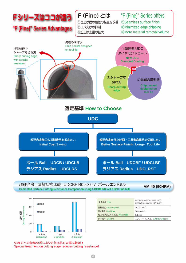
特殊処理でシャープな切れ刃Sharp cutting edgewith special treatment
先端の溝形状Chip pocket designed on tool tip
選定基準 How to Choose
UDC
超硬合金加工の初期費用を抑えたいInitial Cost Saving
超硬合金を仕上げ面・工具寿命重視で切削したいBetter Surface Finish / Longer Tool Life
ボール Ball UDCB / UDCLBラジアス Radius UDCLRS
ボール Ball UDCBF / UDCLBFラジアス Radius UDCLRSF
VM-40 (90HRA)
切れ刃への特殊処理により切削抵抗を大幅に軽減!Special treatment on cutting edge reduces cutting resistance!
超硬合金 切削抵抗比較 UDCBF R0.5×0.7 ボールエンドミルCemented Carbide Cutting Resistance Comparison using UDCBF R0.5x0.7 Ball End Mill
①新開発UDCダイヤモンドコート
New UDCDiamond Coating
②シャープな切れ刃
Sharp cuttingedge
③先端の溝形状Chip pocketdesigned on
tool tip
F(Fine) とは①仕上げ面の段差の発生を改善 ②コバ欠けの抑制 ③加工除去量の拡大
"F (Fine)" Series offers①Seamless surface finish②Minimized edge chipping③More material removal volume
FF
X 方向 Y 方向 Z 方向
"F (Fine)" Series Advantages
X Direction Y Direction Z Direction
超硬合金 φ20 テーパ 15°形状 UDCBF R0.5×0.7 ボールエンドミルCemented Carbide φ20 15° Taper milled with UDCBF R0.5x0.7 Ball End Mill
1
2
3
UDCB UDCBF
UDCB UDCBF
回転速度 Spindle Speed
送り速度 Feed Rate軸方向の切込み深さ Axial Depth
半径方向の切込み深さ Radial Depth
クーラント Coolant
加工時間 Cycle Time
30,000 min-1
300 mm/min
0.05 mm
0.02 mm
エアブロー (ノズル) Air Blow (Nozzle)
55 min 5 sec
30,000 min-1
300 mm/min
0.05 mm
0.25 mm
エアブロー (ノズル) Air Blow (Nozzle)
使用工具 Tool
UDCB 2010-0070 (R0.5×0.7)UDCBF 2010-0070 (R0.5×0.7)UDCLB 2010-0250 (R0.5×2.5×0.7)UDCLBF 2010-0250 (R0.5×2.5×0.7)UDCLB 2010-0400 (R0.5×4×0.7)UDCLBF 2010-0400 (R0.5×4×0.7)
回転速度 Spindle Speed
送り速度 Feed Rate
軸方向の切込み深さ Axial Depth
半径方向の切込み深さ Radial Depth
クーラント Coolant
使用工具 ToolUDCB 2010-0070 (R0.5×0.7)
UDCBF 2010-0070 (R0.5×0.7)
回転速度 Spindle Speed
送り速度 Feed Rate
軸方向の切込み深さ Axial Depth
半径方向の切込み深さ Radial Depth
クーラント Coolant
30,000 min-1
300 mm/min
0.02 mm
0.05 mm
エアブロー (ノズル) Air Blow (Nozzle)
使用工具 ToolUDCB 2010-0070 (R0.5×0.7)
UDCBF 2010-0070 (R0.5×0.7)
除去
体積
Mat
eria
l Rem
oval
Vol
ume
mm
3
全刃長All Flute
有効長 2.5mmEffective Length
有効長 4.0mmEffective Length
VF-10 (93HRA)
超硬合金 被削材のコバ欠け比較 UDCBF R0.5×0.7 ボールエンドミルCemented Carbide Comparison of Edge Chipping using UDCBF R0.5x0.7 Ball End Mill
超硬合金 荒加工における UDCBF ・ UDCLBF の除去体積比較Cemented Carbide Material Removal Volume Comparison on Roughing using UDCBF & UDCLBF
VM-40 (90HRA)
VM-40 (90HRA)
被削材のコバ欠け Edge chipping on work material上面 Surface 100μm
側面 Side 100μm
上面 Surface 100μm
側面 Side 100μm
事例Milling Examples 仕上げ面の段差を改善
Seamless surface finish
コバ欠けの抑制
Minimized edge chipping
加工除去量の拡大More material removal volume
15μm
-15μm形状精度
Form accuracy形状精度
Form accuracy
段差Gap
加工方向Milling direction
加工方向Milling direction
15μm
-15μm
UDCB : 切れ刃のコーティングが損傷し、
加工面に段差が発生
UDCBF : 均一な加工面で寸法精度も良好
UDCB: Coating damage on cutting edge causes milling gap.UDCBF: Uniform surface with excellent dimensional accuracy.
ap
ap
ae
ap
ae
ap
ae

5
回転速度 Spindle Speed
送り速度 Feed Rate軸方向の切込み深さ Axial Depth
クーラント Coolant
使用工具 ToolUDCB 2010-0070 (R0.5×0.7)
UDCBF 2010-0070 (R0.5×0.7)
30,000 min-1
300 mm/min
0.1 mm
エアブロー (ノズル) Air Blow (Nozzle)
特殊処理でシャープな切れ刃Sharp cutting edgewith special treatment
先端の溝形状Chip pocket designed on tool tip
選定基準 How to Choose
UDC
超硬合金加工の初期費用を抑えたいInitial Cost Saving
超硬合金を仕上げ面・工具寿命重視で切削したいBetter Surface Finish / Longer Tool Life
ボール Ball UDCB / UDCLBラジアス Radius UDCLRS
ボール Ball UDCBF / UDCLBFラジアス Radius UDCLRSF
VM-40 (90HRA)
切れ刃への特殊処理により切削抵抗を大幅に軽減!Special treatment on cutting edge reduces cutting resistance!
超硬合金 切削抵抗比較 UDCBF R0.5×0.7 ボールエンドミルCemented Carbide Cutting Resistance Comparison using UDCBF R0.5x0.7 Ball End Mill
①新開発UDCダイヤモンドコート
New UDCDiamond Coating
②シャープな切れ刃
Sharp cuttingedge
③先端の溝形状Chip pocketdesigned on
tool tip
F(Fine) とは①仕上げ面の段差の発生を改善 ②コバ欠けの抑制 ③加工除去量の拡大
"F (Fine)" Series offers①Seamless surface finish②Minimized edge chipping③More material removal volume
FF
X 方向 Y 方向 Z 方向
"F (Fine)" Series Advantages
X Direction Y Direction Z Direction
超硬合金 φ20 テーパ 15°形状 UDCBF R0.5×0.7 ボールエンドミルCemented Carbide φ20 15° Taper milled with UDCBF R0.5x0.7 Ball End Mill
1
2
3
UDCB UDCBF
UDCB UDCBF
回転速度 Spindle Speed
送り速度 Feed Rate軸方向の切込み深さ Axial Depth
半径方向の切込み深さ Radial Depth
クーラント Coolant
加工時間 Cycle Time
30,000 min-1
300 mm/min
0.05 mm
0.02 mm
エアブロー (ノズル) Air Blow (Nozzle)
55 min 5 sec
30,000 min-1
300 mm/min
0.05 mm
0.25 mm
エアブロー (ノズル) Air Blow (Nozzle)
使用工具 Tool
UDCB 2010-0070 (R0.5×0.7)UDCBF 2010-0070 (R0.5×0.7)UDCLB 2010-0250 (R0.5×2.5×0.7)UDCLBF 2010-0250 (R0.5×2.5×0.7)UDCLB 2010-0400 (R0.5×4×0.7)UDCLBF 2010-0400 (R0.5×4×0.7)
回転速度 Spindle Speed
送り速度 Feed Rate
軸方向の切込み深さ Axial Depth
半径方向の切込み深さ Radial Depth
クーラント Coolant
使用工具 ToolUDCB 2010-0070 (R0.5×0.7)
UDCBF 2010-0070 (R0.5×0.7)
回転速度 Spindle Speed
送り速度 Feed Rate
軸方向の切込み深さ Axial Depth
半径方向の切込み深さ Radial Depth
クーラント Coolant
30,000 min-1
300 mm/min
0.02 mm
0.05 mm
エアブロー (ノズル) Air Blow (Nozzle)
使用工具 ToolUDCB 2010-0070 (R0.5×0.7)
UDCBF 2010-0070 (R0.5×0.7)
除去
体積
Mat
eria
l Rem
oval
Vol
ume
mm
3
全刃長All Flute
有効長 2.5mmEffective Length
有効長 4.0mmEffective Length
VF-10 (93HRA)
超硬合金 被削材のコバ欠け比較 UDCBF R0.5×0.7 ボールエンドミルCemented Carbide Comparison of Edge Chipping using UDCBF R0.5x0.7 Ball End Mill
超硬合金 荒加工における UDCBF ・ UDCLBF の除去体積比較Cemented Carbide Material Removal Volume Comparison on Roughing using UDCBF & UDCLBF
VM-40 (90HRA)
VM-40 (90HRA)
被削材のコバ欠け Edge chipping on work material上面 Surface 100μm
側面 Side 100μm
上面 Surface 100μm
側面 Side 100μm
事例Milling Examples 仕上げ面の段差を改善
Seamless surface finish
コバ欠けの抑制
Minimized edge chipping
加工除去量の拡大More material removal volume
15μm
-15μm形状精度
Form accuracy形状精度
Form accuracy
段差Gap
加工方向Milling direction
加工方向Milling direction
15μm
-15μm
UDCB : 切れ刃のコーティングが損傷し、
加工面に段差が発生
UDCBF : 均一な加工面で寸法精度も良好
UDCB: Coating damage on cutting edge causes milling gap.UDCBF: Uniform surface with excellent dimensional accuracy.
ap
ap
ae
ap
ae
ap
ae

6
合計Total
16 15:04:32
超硬合金 ベベルギア金型加工事例 UDCLB / UDCLBF R1 ・ R1.5 ・ R2Bevel Gear on Cemented Carbide of VU-70(83HRA) milled with UDCLB / UDCLBF R1・R1.5・R2
バインダレス超硬合金 (90HRA ~ ) UDCB R0.5・ R1 ボールエンドミル レンズアレイ加工事例 Binderless Cemented Carbide (90HRA~) Lens Array milled with UDCB R0.5 & R1 Ball End Mills
加工プロセス Milling Process
協賛 : 株式会社 C&G システムズ CAD/CAM : CAM-TOOL
サイズ Size : 25 × 25 mm
加工プロセス Milling Process
5 軸加工機により曲面を高精度に加工5 axis machining provides high quality curved surface.
実加工時間 : 8 時間 49 分
Actual cycle time : 8 h 49 min
クーラント : エアブローCoolant : Air blow
サイズ :φ44 × 12.75 mmSize
使用工具 16 本、 15 時間で加工完了
The number of tool used for processing was 16 pieces, and the processing completed in 15 hours.
クーラント : エアブローCoolant : Air blow
工程名 Process
等高線高効率荒取りZ-Level High Efficiency Roughing
等高取り残し加工Z-Level Re-machining
複合面沿い加工Curve Control Along Surface
等高線仕上げZ-Level Finishing
等高線仕上げZ-Level Finishing
使用工具Tool
UDCB 2020-0140 (R1 × 1.4)
UDCB 2010-0070 (R0.5 × 0.7)
UDCB 2010-0070 (R0.5 × 0.7)
UDCB 2010-0070 (R0.5 × 0.7)
UDCB 2010-0070 (R0.5 × 0.7)
30,000
30,000
30,000
30,000
30,000
回転速度Spindle Speed
(min-1)
送り速度Feed Rate(mm/min)
300
300
300
300
300
0.1
0.05
-
0.3
0.2
0.02
-
-
5
6
使用工具 Tool
回転速度 Spindle Speed
送り速度 Feed Rate
軸方向の切込み深さ Axial Depth
半径方向の切込み深さ Radial Depth
クーラント Coolant
加工時間 Cycle Time
除去体積 Material Removal Volume
0.05 mm
0.25 mm
43 min
86.3 mm3
0.028 mm
0.02 mm
2 h 17 min
12.0 mm3
VU-70 (83HRA)
(mm) (mm)
UDCBレンズアレイ加工動画
Lens ArrayMilling Video
UDCBFチップ形状加工動画
UDCBF SeriesIndexable Insert Mold
Milling Video
3軸加工機で製作可能!Available with 3axis machine !
4 超硬合金 チップ形状 UDCBF R0.5×0.7 ボールエンドミル VM-40 (90HRA)
30,000 min-1
300 mm/min
エアブロー (ノズル) Air Blow (Nozzle)
荒加工Roughing
仕上げ加工Finishing
※荒 ・ 仕上げ加工で各 1 本、 合計 2 本使用 One End Mill for both roughing and finishing processes. Total 2 tools are used.
荒加工後の工具Tool after roughing
仕上げ加工後の工具Tool after finishing
仕上げ加工後のワーク Work sample after finishing
上面 Surface 側面 Side
■仕上げ面粗さ測定 Surface Roughness
サイズ Size : 20 × 20 × 10 mm
Ra: 0.054μmRz: 0.408μm
Ra: 0.051μmRz: 0.399μm
Ra: 0.068μmRz: 0.520μm
Cemented Carbide Indexable Insert Mold milled with UDCBF R0.5x0.7 Ball End Mill
面粗さ良好!
Excellent surface quality!
コバ欠けなし!
Minimized edge chipping
UDCBF 2010-0070 (R0.5×0.7)
200.00μm
Axial Depth Radial Depth
ap
ae
ap ae
UDCLB / UDCLBF 超硬直彫りべベルギア加工動画UDCLB / UDCLBF
Direct milling for Cemented CarbideMilling Video of Bevel Gear
回転速度
SpindleSpeed
送り速度
FeedRate
AxialDepth
RadialDepth
仕上げ代
FinishingAllowance
(min-1) (mm/min) (mm) (mm) (mm)
UDCLB 2040-0800 (R2 × 8) 8,250 300 0.5 0.2 0.03 3 2:12:31UDCLB 2040-1000 (R2 × 10) 8,250 300 0.5 0.2 0.03 2 0:29:24UDCLB 2030-0600 (R1.5 × 6) 11,000 280 0.38 0.15 0.03 1 0:22:33UDCLB 2030-1000 (R1.5 × 10) 11,000 280 0.3 0.15 0.03 1 0:23:27UDCLB 2030-1000 (R1.5 × 10) 11,000 280 (0.005) - 0.015 1 1:08:35UDCLB 2030-1000 (R1.5 × 10) 11,000 280 (0.002) - 0.005 1 1:36:52UDCLB 2020-0600 (R1 × 6) 16,500 420 0.12 0.05 0.015 1 0:52:28UDCLB 2020-0800 (R1 × 8) 16,500 420 0.12 0.05 0.015 1 0:49:56UDCLB 2020-0800 (R1 × 8) 16,500 420 0.09 - 0.005 1 1:09:32UDCLBF 2020-0800 (R1 × 8) 20,000 200 - 0.12 0 1 0:41:20UDCLBF 2020-0800 (R1 × 8) 20,000 200 (0.001) - 0 2 3:39:54UDCLBF 2020-0800 (R1 × 8) 20,000 200 0.09 - 0 0:34:00UDCLBF 2020-0800 (R1 × 8) 20,000 200 - 0.08 0 1:04:00
工程名Process
使用工具Tool
加工時間
Cycle Time
工具本数
Quantity
荒Roughing
中荒Roughing
中仕上げSemi-finishing
隅取りCorner finishing
仕上げFinishing
1
ap ae

7
合計Total
16 15:04:32
超硬合金 ベベルギア金型加工事例 UDCLB / UDCLBF R1 ・ R1.5 ・ R2Bevel Gear on Cemented Carbide of VU-70(83HRA) milled with UDCLB / UDCLBF R1・R1.5・R2
バインダレス超硬合金 (90HRA ~ ) UDCB R0.5・ R1 ボールエンドミル レンズアレイ加工事例 Binderless Cemented Carbide (90HRA~) Lens Array milled with UDCB R0.5 & R1 Ball End Mills
加工プロセス Milling Process
協賛 : 株式会社 C&G システムズ CAD/CAM : CAM-TOOL
サイズ Size : 25 × 25 mm
加工プロセス Milling Process
5 軸加工機により曲面を高精度に加工5 axis machining provides high quality curved surface.
実加工時間 : 8 時間 49 分
Actual cycle time : 8 h 49 min
クーラント : エアブローCoolant : Air blow
サイズ :φ44 × 12.75 mmSize
使用工具 16 本、 15 時間で加工完了
The number of tool used for processing was 16 pieces, and the processing completed in 15 hours.
クーラント : エアブローCoolant : Air blow
工程名 Process
等高線高効率荒取りZ-Level High Efficiency Roughing
等高取り残し加工Z-Level Re-machining
複合面沿い加工Curve Control Along Surface
等高線仕上げZ-Level Finishing
等高線仕上げZ-Level Finishing
使用工具Tool
UDCB 2020-0140 (R1 × 1.4)
UDCB 2010-0070 (R0.5 × 0.7)
UDCB 2010-0070 (R0.5 × 0.7)
UDCB 2010-0070 (R0.5 × 0.7)
UDCB 2010-0070 (R0.5 × 0.7)
30,000
30,000
30,000
30,000
30,000
回転速度Spindle Speed
(min-1)
送り速度Feed Rate(mm/min)
300
300
300
300
300
0.1
0.05
-
0.3
0.2
0.02
-
-
5
6
使用工具 Tool
回転速度 Spindle Speed
送り速度 Feed Rate
軸方向の切込み深さ Axial Depth
半径方向の切込み深さ Radial Depth
クーラント Coolant
加工時間 Cycle Time
除去体積 Material Removal Volume
0.05 mm
0.25 mm
43 min
86.3 mm3
0.028 mm
0.02 mm
2 h 17 min
12.0 mm3
VU-70 (83HRA)
(mm) (mm)
UDCBレンズアレイ加工動画
Lens ArrayMilling Video
UDCBFチップ形状加工動画
UDCBF SeriesIndexable Insert Mold
Milling Video
3軸加工機で製作可能!Available with 3axis machine !
4 超硬合金 チップ形状 UDCBF R0.5×0.7 ボールエンドミル VM-40 (90HRA)
30,000 min-1
300 mm/min
エアブロー (ノズル) Air Blow (Nozzle)
荒加工Roughing
仕上げ加工Finishing
※荒 ・ 仕上げ加工で各 1 本、 合計 2 本使用 One End Mill for both roughing and finishing processes. Total 2 tools are used.
荒加工後の工具Tool after roughing
仕上げ加工後の工具Tool after finishing
仕上げ加工後のワーク Work sample after finishing
上面 Surface 側面 Side
■仕上げ面粗さ測定 Surface Roughness
サイズ Size : 20 × 20 × 10 mm
Ra: 0.054μmRz: 0.408μm
Ra: 0.051μmRz: 0.399μm
Ra: 0.068μmRz: 0.520μm
Cemented Carbide Indexable Insert Mold milled with UDCBF R0.5x0.7 Ball End Mill
面粗さ良好!
Excellent surface quality!
コバ欠けなし!
Minimized edge chipping
UDCBF 2010-0070 (R0.5×0.7)
200.00μm
Axial Depth Radial Depth
ap
ae
ap ae
UDCLB / UDCLBF 超硬直彫りべベルギア加工動画UDCLB / UDCLBF
Direct milling for Cemented CarbideMilling Video of Bevel Gear
回転速度
SpindleSpeed
送り速度
FeedRate
AxialDepth
RadialDepth
仕上げ代
FinishingAllowance
(min-1) (mm/min) (mm) (mm) (mm)
UDCLB 2040-0800 (R2 × 8) 8,250 300 0.5 0.2 0.03 3 2:12:31UDCLB 2040-1000 (R2 × 10) 8,250 300 0.5 0.2 0.03 2 0:29:24UDCLB 2030-0600 (R1.5 × 6) 11,000 280 0.38 0.15 0.03 1 0:22:33UDCLB 2030-1000 (R1.5 × 10) 11,000 280 0.3 0.15 0.03 1 0:23:27UDCLB 2030-1000 (R1.5 × 10) 11,000 280 (0.005) - 0.015 1 1:08:35UDCLB 2030-1000 (R1.5 × 10) 11,000 280 (0.002) - 0.005 1 1:36:52UDCLB 2020-0600 (R1 × 6) 16,500 420 0.12 0.05 0.015 1 0:52:28UDCLB 2020-0800 (R1 × 8) 16,500 420 0.12 0.05 0.015 1 0:49:56UDCLB 2020-0800 (R1 × 8) 16,500 420 0.09 - 0.005 1 1:09:32UDCLBF 2020-0800 (R1 × 8) 20,000 200 - 0.12 0 1 0:41:20UDCLBF 2020-0800 (R1 × 8) 20,000 200 (0.001) - 0 2 3:39:54UDCLBF 2020-0800 (R1 × 8) 20,000 200 0.09 - 0 0:34:00UDCLBF 2020-0800 (R1 × 8) 20,000 200 - 0.08 0 1:04:00
工程名Process
使用工具Tool
加工時間
Cycle Time
工具本数
Quantity
荒Roughing
中荒Roughing
中仕上げSemi-finishing
隅取りCorner finishing
仕上げFinishing
1
ap ae

8
8
超硬合金 UDCLRS φ2×CR0.05×2 ロングネックラジアスエンドミルCemented Carbide UDCLRS φ2xCR0.05x2 Long Neck Radius End Mill
10 アルミナ ・ ジルコニア ヘクサロビュラ形状 UDCB R0.5×0.7 ボールエンドミルAlumina / Zirconia Hexalobular milled with UDCB R0.5x0.7 Ball End Mill
仕上げ加工後 After Finishing
加工条件Milling Conditions
荒加工Roughing
20,000 min-1
750 mm/min
0.9 mm
0.01 mm
エアブロー Air Blow
10 x 8 x 1.8 mm
16 m
オイルミスト Oil Mist
0.01 mm
-
144 mm3 -
20,000 min-1
100 mm/min0.01 mm 底面側 Bottom Surface0.9 mm 側面側 Side
(0.01 mm×5回 Times)
仕上げ加工Finishing
回転速度 Spindle Speed使用工具 Tool
クーラント Coolant
加工サイズ Milling Size
加工距離 Milling Distance
送り速度 Feed Rate
軸方向の切り込み深さAxial Depth
除去体積Material Removal Volume
半径方向の切り込み深さRadial Depth
工具突き出し長 Overhang : 15 mm
使用工具 Tool
回転速度 Spindle Speed
送り速度 Feed Rate軸方向の切り込み深さ Axial Depth
半径方向の切り込み深さ Radial Depth
クーラント Coolant
加工時間 Cycle Time
除去体積 Material Removal Volume
UDCB 2010-0070 (R0.5 × 0.7)
アルミナ Aℓ2O3 Alumina / ジルコニア ZrO2 Zirconia
30,000 min-1
300 mm/min
0.05 mm
0.05 mm
エアブロー (ノズル) Air Blow (Nozzle)
98 min
88.4 mm3 0.9 mm3/min
被削材 Work Material
※荒 ・ 仕上げ加工で各 1 本、 合計 2 本使用
One End Mill for both roughing and finishing processes. Total 2 tools are used.
Ra: 0.069μmRz: 0.535μmカットオフ長 : 0.25 mmCut-off length : 0.25 mm
Ra: 0.010μmRz: 0.078μmカットオフ長 : 0.08 mmCut-off length : 0.08 mm
ヘクサロビュラ形状 サイズ : φ9 x 深さ 2.2 mmHexalobular Size : φ9 x 2.2 mm depth
アルミナ Aℓ2O3
Aluminaジルコニア ZrO2
Zirconia
底面の状態 Bottom Surface Appearance
仕上げ加工後のワークWork sample after finishing
9 VM-40 (90HRA)
*Designed for the materials stated in the application chart of each series.
0.01 mm 底面側 Bottom Surface0.05 mm 側面側 Side
むしれの無い、鏡面加工!
Mirror surface finishwith zero pits!
UDCLRS側面加工動画
Side Milling Video
超硬だけじゃない!
Versatile coating ! *
UDCLRS 2020-005-020
超硬合金 剣山形状 UDCLB R0.5×5 ロングネックボールエンドミルCemented Carbide Micro Needles milled with UDCLB R0.5x5 Long Neck Ball End Mill
超硬合金 ヘクサロビュラ形状 UDCLB R0.5×5 ・ R0.5×2 ロングネックボールエンドミルCemented Carbide Hexalobular milled with UDCLB R0.5x5 & R0.5x2 Long Neck Ball End Mills
サイズ : 6 x 6 x 深さ 5 mmサイズ (ピン) : 先端径 0.2 mm 深さ 5 mm
根元径 0.34 mm
サイズ :φ9 深さ 6 mmSize: φ9, 6 mm depth
使用工具 Tool
回転速度 Spindle Speed
送り速度 Feed Rate
軸方向の切り込み深さ Axial Depth
半径方向の切り込み深さ Radial Depth
クーラント Coolant
加工時間 Cycle Time
除去体積 Material Removal Volume
UDCLB 2010-0500 (R0.5×5 mm)
R0.5 ボールエンドミルで加工深さ 6 mm までの深彫りを、 驚異的な 『深』 切り込みで実現しました。R0.5 ball End Mill reaches deep into thepocket (6 mm) with a great depth of cut.
Total : 156 minTotal : 274.4 mm3
加工条件Milling Conditions
工程1Process 1
荒加工深さ 3.5 mm まで
工程 2Process 2
荒加工深さ 6 mm まで
工程 3Process 3
仕上げ加工
使用工具 Tool回転速度 Spindle Speed
クーラント Coolant加工時間 Cycle Time
送り速度 Feed Rate軸方向の切り込み深さ Axial Depth
除去体積Material Removal Volume
半径方向の切り込み深さRadial Depth
RoughingMax 3.5 mm depth
RoughingMax 6 mm depth
UDCLB 2010-0500UDCLB 2010-0200
エアブロー Air Blow
30,000 min-1
300 mm/min
0.05 mm
0.3 mm
58 min
152.8 mm3 120 mm3 1.6 mm3
0.25 mm
64 min
0.005 mm
0.03 mm
34 min
Finishing
※加工後の写真です※After finishing process
①
深さ~ 2.5 mm まで
Max 2.5 mm depth
②
深さ~ 5.0 mm まで
Max 5.0 mm depth
30,000 min-1
300 mm/min
0.1 mm
エアブロー Air Blow
0.05 mm
52 min
80.1 mm3
0.05 mm(底面 Bottom 0.02 mm)
39 min
76.5 mm3
Overall size : 6 x 6 x 5 mm depthPin size : Tip diameter: 0.2 mm Pin length: 5 mm Root diameter: 0.34 mm
7
8
※①②で各1本、合計2本使用
One tool for ① and ②. Total 2 tools are used.
VF-20 (92.5HRA)
VF-20 (92.5HRA)
深彫り加工もこのとおり!Super durabledeep milling!
UDCLBヘクサロビュラ形状加工動画
Hexalobular Milling Video
超硬なのにこの細さ! わずかφ0.2 mm!!Diameter 0.2 mm !Carbide micro pin.
ap
ae
ap
ae
ap
aeap
ae

9
8
超硬合金 UDCLRS φ2×CR0.05×2 ロングネックラジアスエンドミルCemented Carbide UDCLRS φ2xCR0.05x2 Long Neck Radius End Mill
10 アルミナ ・ ジルコニア ヘクサロビュラ形状 UDCB R0.5×0.7 ボールエンドミルAlumina / Zirconia Hexalobular milled with UDCB R0.5x0.7 Ball End Mill
仕上げ加工後 After Finishing
加工条件Milling Conditions
荒加工Roughing
20,000 min-1
750 mm/min
0.9 mm
0.01 mm
エアブロー Air Blow
10 x 8 x 1.8 mm
16 m
オイルミスト Oil Mist
0.01 mm
-
144 mm3 -
20,000 min-1
100 mm/min0.01 mm 底面側 Bottom Surface0.9 mm 側面側 Side
(0.01 mm×5回 Times)
仕上げ加工Finishing
回転速度 Spindle Speed使用工具 Tool
クーラント Coolant
加工サイズ Milling Size
加工距離 Milling Distance
送り速度 Feed Rate
軸方向の切り込み深さAxial Depth
除去体積Material Removal Volume
半径方向の切り込み深さRadial Depth
工具突き出し長 Overhang : 15 mm
使用工具 Tool
回転速度 Spindle Speed
送り速度 Feed Rate軸方向の切り込み深さ Axial Depth
半径方向の切り込み深さ Radial Depth
クーラント Coolant
加工時間 Cycle Time
除去体積 Material Removal Volume
UDCB 2010-0070 (R0.5 × 0.7)
アルミナ Aℓ2O3 Alumina / ジルコニア ZrO2 Zirconia
30,000 min-1
300 mm/min
0.05 mm
0.05 mm
エアブロー (ノズル) Air Blow (Nozzle)
98 min
88.4 mm3 0.9 mm3/min
被削材 Work Material
※荒 ・ 仕上げ加工で各 1 本、 合計 2 本使用
One End Mill for both roughing and finishing processes. Total 2 tools are used.
Ra: 0.069μmRz: 0.535μmカットオフ長 : 0.25 mmCut-off length : 0.25 mm
Ra: 0.010μmRz: 0.078μmカットオフ長 : 0.08 mmCut-off length : 0.08 mm
ヘクサロビュラ形状 サイズ : φ9 x 深さ 2.2 mmHexalobular Size : φ9 x 2.2 mm depth
アルミナ Aℓ2O3
Aluminaジルコニア ZrO2
Zirconia
底面の状態 Bottom Surface Appearance
仕上げ加工後のワークWork sample after finishing
9 VM-40 (90HRA)
*Designed for the materials stated in the application chart of each series.
0.01 mm 底面側 Bottom Surface0.05 mm 側面側 Side
むしれの無い、鏡面加工!
Mirror surface finishwith zero pits!
UDCLRS側面加工動画
Side Milling Video
超硬だけじゃない!
Versatile coating ! *
UDCLRS 2020-005-020
超硬合金 剣山形状 UDCLB R0.5×5 ロングネックボールエンドミルCemented Carbide Micro Needles milled with UDCLB R0.5x5 Long Neck Ball End Mill
超硬合金 ヘクサロビュラ形状 UDCLB R0.5×5 ・ R0.5×2 ロングネックボールエンドミルCemented Carbide Hexalobular milled with UDCLB R0.5x5 & R0.5x2 Long Neck Ball End Mills
サイズ : 6 x 6 x 深さ 5 mmサイズ (ピン) : 先端径 0.2 mm 深さ 5 mm
根元径 0.34 mm
サイズ :φ9 深さ 6 mmSize: φ9, 6 mm depth
使用工具 Tool
回転速度 Spindle Speed
送り速度 Feed Rate
軸方向の切り込み深さ Axial Depth
半径方向の切り込み深さ Radial Depth
クーラント Coolant
加工時間 Cycle Time
除去体積 Material Removal Volume
UDCLB 2010-0500 (R0.5×5 mm)
R0.5 ボールエンドミルで加工深さ 6 mm までの深彫りを、 驚異的な 『深』 切り込みで実現しました。R0.5 ball End Mill reaches deep into thepocket (6 mm) with a great depth of cut.
Total : 156 minTotal : 274.4 mm3
加工条件Milling Conditions
工程1Process 1
荒加工深さ 3.5 mm まで
工程 2Process 2
荒加工深さ 6 mm まで
工程 3Process 3
仕上げ加工
使用工具 Tool回転速度 Spindle Speed
クーラント Coolant加工時間 Cycle Time
送り速度 Feed Rate軸方向の切り込み深さ Axial Depth
除去体積Material Removal Volume
半径方向の切り込み深さRadial Depth
RoughingMax 3.5 mm depth
RoughingMax 6 mm depth
UDCLB 2010-0500UDCLB 2010-0200
エアブロー Air Blow
30,000 min-1
300 mm/min
0.05 mm
0.3 mm
58 min
152.8 mm3 120 mm3 1.6 mm3
0.25 mm
64 min
0.005 mm
0.03 mm
34 min
Finishing
※加工後の写真です※After finishing process
①
深さ~ 2.5 mm まで
Max 2.5 mm depth
②
深さ~ 5.0 mm まで
Max 5.0 mm depth
30,000 min-1
300 mm/min
0.1 mm
エアブロー Air Blow
0.05 mm
52 min
80.1 mm3
0.05 mm(底面 Bottom 0.02 mm)
39 min
76.5 mm3
Overall size : 6 x 6 x 5 mm depthPin size : Tip diameter: 0.2 mm Pin length: 5 mm Root diameter: 0.34 mm
7
8
※①②で各1本、合計2本使用
One tool for ① and ②. Total 2 tools are used.
VF-20 (92.5HRA)
VF-20 (92.5HRA)
深彫り加工もこのとおり!Super durabledeep milling!
UDCLBヘクサロビュラ形状加工動画
Hexalobular Milling Video
超硬なのにこの細さ! わずかφ0.2 mm!!Diameter 0.2 mm !Carbide micro pin.
ap
ae
ap
ae
ap
aeap
ae

10
UDCBFサイズ Size R0.1~R3
超硬合金・硬脆材を切削できるボールエンドミル(UDCB の上級バージョン)。改良した刃形状とダイヤモンドコーティング UDC を採用し、加工除去体積を大幅に向上。ボール先端に設けた溝により、抜群の仕上げ面を実現。切れ刃に特殊処理を施し、被削材のコバ欠けや段差を最大限に抑制し、中荒から仕上げ加工に幅広く適応。
Ball type End Mills for milling Cemented Carbide and Hard Brittle (Non-Metallic) Materials. Upgraded version of UDCB.New Diamond coating and tool geometry increase material removal volume.Chip pocket designed on tool tip improves the surface finishing quality.Special cutting edge treatment helps to avoid the edge chipping & level gap. Recommended to use on semi-roughing & finishing process.
特長 Features
シャンクテーパ角は目安です。ワークとの干渉が心配な場合は必ず実測して確認してください。シャンク部とワークの接触にご注意ください。
The shank taper angle shown is not an exact value and to avoid contact with the workpiece, we recommend the user controls the precise value of this angle. Shank taper angle should not make contact with the work piece.
合計 16型番 Total 16 models 単位 Unit(mm)
型番Model
Number
ボール半径Radius ofBall Nose
R
刃長Lengthof Cut
ℓ
シャンクテーパ角Shank Taper
Angle
Bta
全長OverallLength
L
シャンク径Shank
Diameter
φd
定価Price
¥
UDCBF 2002-0014 R0.1 0.14 16° 50 4 47,000
UDCBF 2003-0021 R0.15 0.21 16° 50 4 47,000
UDCBF 2004-0028 R0.2 0.28 16° 50 4 42,800
UDCBF 2005-0035 R0.25 0.35 16° 50 4 42,800
UDCBF 2006-0042 R0.3 0.42 16° 50 4 38,400
UDCBF 2007-0049 R0.35 0.49 16° 50 4 38,400
UDCBF 2008-0056 R0.4 0.56 16° 50 4 38,400
UDCBF 2009-0063 R0.45 0.63 16° 50 4 38,400
UDCBF 2010-0070 R0.5 0.7 16° 50 4 38,400
UDCBF 2012-0084 R0.6 0.84 16° 50 4 38,400
UDCBF 2015-0105 R0.75 1.05 16° 50 4 38,400
UDCBF 2020-0140 R1 1.4 16° 50 4 38,400
UDCBF 2030-0210 R1.5 2.1 16° 60 6 42,300
UDCBF 2040-0280 R2 2.8 16° 60 6 42,300
UDCBF 2050-0350 R2.5 3.5 16° 60 6 42,300
UDCBF 2060-0420 R3 4.2 ― 60 6 42,300
対応被削材表(☆◎○の順に推奨)Material Applications(☆ Highly Recommended ◎ Recommended ○ Suggested)被 削 材 Work Material
炭素鋼CARBONSTEELS
S45CS55C
合金鋼ALLOY
STEELSSK / SCM
SUS
プリハードン鋼PREHARDENED
STEELSNAKHPM
焼入れ鋼HARDENED STEELS
鋳鉄CAST IRON
アルミ合金ALUMINUM
ALLOYS
グラファイトGRAPHITE
銅COPPER
樹脂PLASTICS
ガラス入り樹脂GLASSFILLED
PLASTICS
チタン合金TITANIUMALLOYS
超耐熱合金HEAT
RESISTANTALLOYS
超硬合金CEMENTED
CARBIDE
硬脆材HARD BRITTLE
(NON-METALLIC)MATERIALS~ 55HRC ~ 60HRC ~ 70HRC
○ ☆ ◎※
※硬脆材:セラミックス(アルミナ、ジルコニアなど)、ガラスなど Hard Brittle (Non-Metallic) Materials: Ceramics (Alumina, Zirconia, etc.), Glasses and etc.
2 枚刃 2 Flutes 超硬合金・硬脆材加工用ハイグレードボールエンドミル High-grade Ball End Mills for Cemented Carbide and Hard Brittle Materials
ラベルに実測の外径とR精度を記載しております。高精度加工にお役立てください。Diameter and Ball R accuracy measurements are printed on the label to support High Precision milling.
SAMPLESAMPLE
ラベルサンプル Label Sample
日本特許取得Patented in Japan

11
UDCBF 切削条件表 Milling Conditions
備考:・切削抵抗が大きいため、剛性の低い機械での加工は推奨できません。・加工機は十分な暖機運転を行い、主軸の伸びが安定してから加工を開始してください。・工具の突き出し長は最低限としてください。・コーティングがつきまわったシャンク部はチャッキングしないでください。刃先の振れが大きくなったり、工具が抜けなくなることがあります。・加工機上での刃先の振れを確認し、小さい振れで加工を実施してください。・アプローチは傾斜もしくはヘリカルを推奨致します(傾斜角度は 5°以下推奨) 。・回転速度を下げる場合は、送り速度も同じ比率で下げてください。・超硬合金加工においては、エアブローが最も工具寿命を延ばしますが、油性切削油やオイルミストも使用できます。・硬脆材加工においては、水溶性切削油を推奨します。・被削材によっては切りくずが重いことがありますので、エアブローやクーラントを加工点に確実に供給し、切りくずを除去してください。・加工状況によっては火花が出ることがありますので、発熱や発火にご注意ください。・切りくずや粉塵が人体に入らないように、保護めがねやマスクなどを必ず着用してください。・切りくずや粉塵が加工機の機構部品に入り込む可能性がありますので、別途対策を推奨致します。
Note:・This application requires a high cutting force. A machine with poor rigidity and high vibration is not recommended.・Allow sufficient machine and spindle warm-up time for stability and to remove any expansion of the main spindle before running the program.・Tool setting length should achieve the least possible overhang.・Avoid contact with the coated area of the shank. This will prevent tip vibration and tool jamming in the collet / holder.・Run-out and vibration should be checked dynamically at the tool point while mounted in the machine and both should achieve the lowest level possible.・Use an inclined or helical approach (Recommended inclination angle: <5 degree).・Decrease both spindle speed and feed rate proportionally.・Air blow is highly recommended for longer tool life. Both oil mist and oil coolant are alternatives.・Recommend water soluble coolant for Hard Brittle (Non-Metallic) Materials.・When milling some work pieces, heavier chips may be created. To evacuate these chips it is important to accurately position the coolant nozzle on the milling part.・Remove chips to prevent heat generation and ignition during milling process.・Protective gear, such as safety glasses and face guards are required when milling.・Chips / dust generated while milling can have adverse affects on the machine parts if they are not properly evacuated. Take steps to assure proper evacuation.
この条件表の超硬合金については、VF-20, VM-40, VC-70, VU-70(CIS 規格)を、硬脆材についてはアルミナをもとに作成しており、切削条件の目安を示すものです。加工する超硬合金や硬脆材の種類により、工具寿命に差があります。実際の加工では、超硬合金、硬脆材の材種、加工形状、機械剛性、主軸などの加工環境により、加工条件の最適化が必要となる場合があります。
These milling parameters are based on VF-20, VM-40, VC-70, VU-70 (CIS standard) for Cemented Carbide, and Alumina for Hard Brittle Materials. These are for reference only.Tool life may differ depending on the type of Cemented Carbide / Hard Brittle Materials.For best result, fine parameter adjustments may be required, depending on the materials of Cemented Carbide / Hard Brittle Materials; milling shape and strategy; machine rigidity and spindle capability.
※送り速度 2:アプローチや接続移動時の送り速度 Feed Rate2: Feed Rate of Approach and *Connection links.
*Changing from one engagement point to the next.
ap:軸方向の切込み深さ(mm)ae:半径方向の切込み深さ(mm)ap:Axial Depth(mm)ae:Radial Depth(mm)
被削材WORK MATERIAL
超硬合金(≧87HRA)/硬脆材CEMENTED CARBIDE(≧87HRA)/ HARD BRITTLE MATERIALS
超硬合金(<87HRA)CEMENTED CARBIDE(<87HRA)
型番Model
Number
ボール半径Radius ofBall Nose(mm)
刃長Lengthof Cut(mm)
回転速度Spindle Speed(min-1)
送り速度Feed Rate
(mm/min)
※送り速度2※Feed Rate 2
(mm/min)
ap
Axial Depth(mm)
ae
Radial Depth(mm)
回転速度Spindle Speed(min-1)
送り速度Feed Rate
(mm/min)
※送り速度2※Feed Rate 2
(mm/min)
ap
Axial Depth(mm)
ae
Radial Depth(mm)
2002-0014 R0.1 0.14 30,000 100 10 0.01 0.01 30,000 100 10 0.01 0.01
2003-0021 R0.15 0.21 30,000 125 13 0.015 0.03 30,000 125 13 0.015 0.03
2004-0028 R0.2 0.28 30,000 150 15 0.02 0.08 30,000 150 15 0.02 0.08
2005-0035 R0.25 0.35 30,000 175 18 0.025 0.11 30,000 175 18 0.025 0.11
2006-0042 R0.3 0.42 30,000 200 20 0.03 0.14 30,000 200 20 0.03 0.14
2007-0049 R0.35 0.49 30,000 225 23 0.035 0.17 30,000 225 23 0.035 0.17
2008-0056 R0.4 0.56 30,000 250 25 0.04 0.19 30,000 250 25 0.04 0.19
2009-0063 R0.45 0.63 30,000 275 28 0.045 0.22 30,000 275 28 0.045 0.22
2010-0070 R0.5 0.7 30,000 300 30 0.05 0.25 30,000 300 150 0.35 0.075
2012-0084 R0.6 0.84 27,500 275 36 0.06 0.26 25,000 250 125 0.42 0.09
2015-0105 R0.75 1.05 25,000 250 45 0.075 0.27 19,000 190 95 0.525 0.12
2020-0140 R1 1.4 20,000 200 60 0.1 0.3 12,500 125 60 0.7 0.15
2030-0210 R1.5 2.1 20,000 200 100 0.15 0.3 9,000 280 140 0.38 0.15
2040-0280 R2 2.8 18,000 180 90 0.175 0.32 7,200 280 140 0.5 0.2
2050-0350 R2.5 3.5 16,000 160 80 0.225 0.31 6,000 330 170 0.6 0.25
2060-0420 R3 4.2 15,000 150 75 0.3 0.3 5,500 280 140 0.65 0.28

12
UDCLBFサイズ Size R0.1~R3
超硬合金・硬脆材を切削できるロングネックボールエンドミル(UDCLB の上級バージョン)。改良した刃形状とダイヤモンドコーティング UDC を採用し、加工除去体積を大幅に向上。ボール先端に設けた溝により、抜群の仕上げ面を実現。切れ刃に特殊処理を施し、コバ欠けや段差を最大限に抑制し、中荒から仕上げ加工に幅広く対応。
Long Neck Ball type End Mills for milling Cemented Carbide and Hard Brittle (Non-Metallic) Materials. Upgraded version of UDCLB.New Diamond coating and tool geometry increase material removal volume.Chip pocket designed on tool tip improves the surface finishing quality.Special cutting edge treatment helps to avoid the edge chipping & level gap. Recommended to use on semi-roughing & finishing process.
特長 Features
シャンクテーパ角は目安です。ワークとの干渉が心配な場合は必ず実測して確認してください。シャンク部とワークの接触にご注意ください。
The shank taper angle shown is not an exact value and to avoidcontact with the workpiece, we recommend the user controls theprecise value of this angle. Shank taper angle should not makecontact with the work piece.
合計 61型番 Total 61 models 単位 Unit(mm)
型番Model
Number
ボール半径Radius ofBall Nose
R
有効長EffectiveLengthℓ1
刃長Lengthof Cutℓ
首径Neck
Diameterφd1
シャンクテーパ角Shank Taper
AngleBta
全長OverallLength
L
シャンク径Shank
Diameterφd
定価Price
¥
ワーク勾配角に対する実有効長Effective Length by
Inclined Angles
30′ 1° 1°30′ 2° 3°
UDCLBF 2002-0030
R0.1
0.3
0.14 0.18 16°
50 4 47,500 0.30 0.31 0.32 0.32 0.34
UDCLBF 2002-0050 0.5 50 4 47,500 0.51 0.52 0.54 0.55 0.59
UDCLBF 2002-0075 0.75 50 4 47,500 0.77 0.79 0.81 0.84 0.89
UDCLBF 2002-0100 1 50 4 47,500 1.02 1.05 1.09 1.12 1.20
※ UDCLBF 2003-0050
R0.15
0.5
0.21 0.28 16°
50 4 47,500 0.51 0.52 0.53 0.55 0.58
※ UDCLBF 2003-0075 0.75 50 4 47,500 0.76 0.78 0.81 0.83 0.88
※ UDCLBF 2003-0100 1 50 4 47,500 1.02 1.05 1.08 1.11 1.19
UDCLBF 2004-0050
R0.2
0.5
0.28 0.36 16°
50 4 43,300 0.54 0.55 0.56 0.58 0.61
UDCLBF 2004-0100 1 50 4 43,300 1.06 1.08 1.12 1.15 1.22
UDCLBF 2004-0150 1.5 50 4 43,300 1.57 1.62 1.67 1.72 1.83
UDCLBF 2004-0200 2 50 4 43,300 2.09 2.15 2.22 2.29 2.44
※ UDCLBF 2004-0250 2.5 50 4 43,300 2.60 2.68 2.77 2.86 3.06
UDCLBF 2006-0100
R0.3
1
0.42 0.56 16°
50 4 38,900 1.05 1.08 1.11 1.13 1.20
UDCLBF 2006-0150 1.5 50 4 38,900 1.57 1.61 1.66 1.70 1.81
UDCLBF 2006-0200 2 50 4 38,900 2.08 2.14 2.21 2.27 2.42
UDCLBF 2006-0300 3 50 4 38,900 3.12 3.21 3.31 3.41 3.65
UDCLBF 2006-0400 4 50 4 38,900 4.15 4.27 4.41 4.55 4.87
UDCLBF 2006-0500 5 50 4 38,900 5.18 5.34 5.51 5.69 6.09
UDCLBF 2006-0600 6 50 4 38,900 6.21 6.40 6.61 6.83 7.32
対応被削材表(☆◎○の順に推奨)Material Applications(☆ Highly Recommended ◎ Recommended ○ Suggested)被 削 材 Work Material
炭素鋼CARBONSTEELS
S45CS55C
合金鋼ALLOY
STEELSSK / SCM
SUS
プリハードン鋼PREHARDENED
STEELSNAKHPM
焼入れ鋼HARDENED STEELS
鋳鉄CAST IRON
アルミ合金ALUMINUM
ALLOYS
グラファイトGRAPHITE
銅COPPER
樹脂PLASTICS
ガラス入り樹脂GLASSFILLED
PLASTICS
チタン合金TITANIUMALLOYS
超耐熱合金HEAT
RESISTANTALLOYS
超硬合金CEMENTED
CARBIDE
硬脆材HARD BRITTLE
(NON-METALLIC)MATERIALS~ 55HRC ~ 60HRC ~ 70HRC
○ ☆ ◎※
※硬脆材:セラミックス(アルミナ、ジルコニアなど)、ガラスなど Hard Brittle (Non-Metallic) Materials: Ceramics (Alumina, Zirconia, etc.), Glasses and etc.
ラベルに実測の外径とR精度を記載しております。高精度加工にお役立てください。Diameter and Ball R accuracy measurements are printed on the label to support High Precision milling.
2 枚刃 2Flutes 超硬合金・硬脆材加工用ハイグレードロングネックボールエンドミル High-grade Long Neck Ball End Mills for Cemented Carbide and Hard Brittle Materials
SAMPLESAMPLE
ラベルサンプル Label Sample
日本特許取得Patented in Japan
追加4型番Additional 4 Models
※追加型番 Additional model

13
2 枚刃 2Flutes 超硬合金・硬脆材加工用ハイグレードロングネックボールエンドミル High-grade Long Neck Ball End Mills for Cemented Carbide and Hard Brittle Materials
型番Model
Number
ボール半径Radius ofBall Nose
R
有効長EffectiveLengthℓ1
刃長Lengthof Cutℓ
首径Neck
Diameterφd1
シャンクテーパ角Shank Taper
AngleBta
全長OverallLength
L
シャンク径Shank
Diameterφd
定価Price
¥
ワーク勾配角に対する実有効長Effective Length by
Inclined Angles
30′ 1° 1°30′ 2° 3°
UDCLBF 2008-0200
R0.4
2
0.56 0.76 16°
50 4 38,900 2.08 2.14 2.20 2.26 2.40
UDCLBF 2008-0300 3 50 4 38,900 3.11 3.20 3.30 3.40 3.62
UDCLBF 2008-0400 4 50 4 38,900 4.14 4.27 4.40 4.54 4.85
UDCLBF 2008-0500 5 50 4 38,900 5.18 5.33 5.50 5.67 6.07
UDCLBF 2008-0600 6 50 4 38,900 6.21 6.40 6.60 6.81 7.29
UDCLBF 2008-0800 8 50 4 38,900 8.27 8.53 8.80 9.09 9.74
UDCLBF 2010-0150
R0.5
1.5
0.7 0.96 16°
50 4 38,900 1.56 1.60 1.64 1.68 1.77
UDCLBF 2010-0200 2 50 4 38,900 2.08 2.13 2.19 2.25 2.38
UDCLBF 2010-0250 2.5 50 4 38,900 2.59 2.66 2.74 2.81 2.99
UDCLBF 2010-0300 3 50 4 38,900 3.11 3.20 3.29 3.38 3.60
UDCLBF 2010-0400 4 50 4 38,900 4.14 4.26 4.39 4.52 4.83
UDCLBF 2010-0600 6 50 4 38,900 6.20 6.39 6.59 6.80 7.27
UDCLBF 2010-0800 8 50 4 38,900 8.27 8.52 8.79 9.08 9.72
UDCLBF 2010-1000 10 50 4 38,900 10.33 10.65 10.99 11.35 12.17
UDCLBF 2015-0200
R0.75
2
1.05 1.4 16°
50 4 38,900 2.11 2.15 2.20 2.25 2.37
UDCLBF 2015-0400 4 50 4 38,900 4.17 4.28 4.40 4.53 4.81
UDCLBF 2015-0600 6 50 4 38,900 6.23 6.41 6.60 6.81 7.26
UDCLBF 2015-0800 8 50 4 38,900 8.29 8.54 8.80 9.08 9.71
UDCLBF 2015-1000 10 50 4 38,900 10.36 10.67 11.00 11.36 12.16
UDCLBF 2015-1200 12 50 4 38,900 12.42 12.80 13.20 13.64 14.60
UDCLBF 2020-0300
R1
3
1.4 1.9 16°
50 4 38,900 3.20 3.27 3.35 3.43 3.62
UDCLBF 2020-0400 4 50 4 38,900 4.23 4.34 4.45 4.57 4.84
UDCLBF 2020-0600 6 50 4 38,900 6.30 6.47 6.65 6.85 7.29
UDCLBF 2020-0800 8 50 4 38,900 8.36 8.60 8.85 9.13 9.74
UDCLBF 2020-1000 10 50 4 38,900 10.42 10.73 11.06 11.41 12.19
UDCLBF 2020-1200 12 50 4 38,900 12.48 12.86 13.26 13.68 14.63
UDCLBF 2020-1400 14 50 4 38,900 14.55 14.99 15.46 15.96 17.08
UDCLBF 2020-1600 16 50 4 38,900 16.61 17.12 17.66 18.24 19.53
UDCLBF 2020-1800 18 60 4 38,900 18.67 19.25 19.86 20.52 干渉なし No Interference
UDCLBF 2020-2000 20 60 4 38,900 20.74 21.38 22.06 22.79 干渉なし No Interference
UDCLBF 2030-0600
R1.5
6
2.1 2.9 16°
60 6 42,800 6.28 6.44 6.60 6.78 7.18
UDCLBF 2030-0800 8 60 6 42,800 8.34 8.57 8.80 9.06 9.63
UDCLBF 2030-1000 10 60 6 42,800 10.41 10.70 11.01 11.34 12.08
UDCLBF 2030-1200 12 60 6 42,800 12.47 12.83 13.21 13.61 14.52
UDCLBF 2030-1400 14 60 6 42,800 14.53 14.96 15.41 15.89 16.97
UDCLBF 2040-0800
R2
8
2.8 3.9 16°
60 6 42,800 8.33 8.53 8.76 8.99 9.52
UDCLBF 2040-1000 10 60 6 42,800 10.39 10.66 10.96 11.27 11.97
UDCLBF 2040-1500 15 60 6 42,800 15.55 15.99 16.46 16.96 18.09
UDCLBF 2050-1000R2.5
103.5 4.8 16°
60 6 42,800 10.55 10.82 11.10 11.40 12.07
UDCLBF 2050-1500 15 60 6 42,800 15.71 16.14 16.60 17.09 干渉なし No Interference
UDCLBF 2060-1000R3
104.2 5.7 ―
60 6 42,800 干渉なし No Interference
干渉なし No Interference
干渉なし No Interference
干渉なし No Interference
干渉なし No Interference
UDCLBF 2060-1500 15 60 6 42,800 干渉なし No Interference
干渉なし No Interference
干渉なし No Interference
干渉なし No Interference
干渉なし No Interference
14
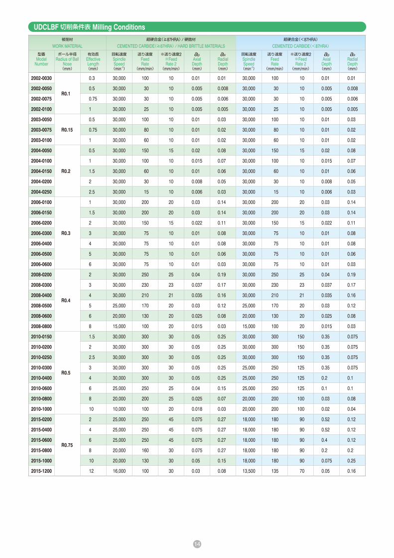
UDCLBF 切削条件表 Milling Conditions被削材
WORK MATERIAL超硬合金(≧87HRA)/硬脆材
CEMENTED CARBIDE(≧87HRA)/ HARD BRITTLE MATERIALS超硬合金(<87HRA)
CEMENTED CARBIDE(<87HRA)
型番Model
Number
ボール半径Radius of Ball
Nose(mm)
有効長Effective Length(mm)
回転速度Spindle Speed(min-1)
送り速度Feed Rate
(mm/min)
※送り速度2※Feed Rate 2
(mm/min)
apAxial
Depth(mm)
aeRadial Depth(mm)
回転速度Spindle Speed(min-1)
送り速度Feed Rate
(mm/min)
※送り速度2※Feed Rate 2
(mm/min)
apAxial
Depth(mm)
aeRadial Depth(mm)
2002-0030
R0.1
0.3 30,000 100 10 0.01 0.01 30,000 100 10 0.01 0.01
2002-0050 0.5 30,000 30 10 0.005 0.008 30,000 30 10 0.005 0.008
2002-0075 0.75 30,000 30 10 0.005 0.006 30,000 30 10 0.005 0.006
2002-0100 1 30,000 25 10 0.005 0.005 30,000 25 10 0.005 0.005
2003-0050
R0.15
0.5 30,000 100 10 0.01 0.03 30,000 100 10 0.01 0.03
2003-0075 0.75 30,000 80 10 0.01 0.02 30,000 80 10 0.01 0.02
2003-0100 1 30,000 60 10 0.01 0.02 30,000 60 10 0.01 0.02
2004-0050
R0.2
0.5 30,000 150 15 0.02 0.08 30,000 150 15 0.02 0.08
2004-0100 1 30,000 100 10 0.015 0.07 30,000 100 10 0.015 0.07
2004-0150 1.5 30,000 60 10 0.01 0.06 30,000 60 10 0.01 0.06
2004-0200 2 30,000 30 10 0.008 0.05 30,000 30 10 0.008 0.05
2004-0250 2.5 30,000 15 10 0.006 0.03 30,000 15 10 0.006 0.03
2006-0100
R0.3
1 30,000 200 20 0.03 0.14 30,000 200 20 0.03 0.14
2006-0150 1.5 30,000 200 20 0.03 0.14 30,000 200 20 0.03 0.14
2006-0200 2 30,000 150 15 0.022 0.11 30,000 150 15 0.022 0.11
2006-0300 3 30,000 75 10 0.01 0.08 30,000 75 10 0.01 0.08
2006-0400 4 30,000 75 10 0.01 0.08 30,000 75 10 0.01 0.08
2006-0500 5 30,000 75 10 0.01 0.06 30,000 75 10 0.01 0.06
2006-0600 6 30,000 75 10 0.01 0.03 30,000 75 10 0.01 0.03
2008-0200
R0.4
2 30,000 250 25 0.04 0.19 30,000 250 25 0.04 0.19
2008-0300 3 30,000 230 23 0.037 0.17 30,000 230 23 0.037 0.17
2008-0400 4 30,000 210 21 0.035 0.16 30,000 210 21 0.035 0.16
2008-0500 5 25,000 170 20 0.03 0.12 25,000 170 20 0.03 0.12
2008-0600 6 20,000 130 20 0.025 0.08 20,000 130 20 0.025 0.08
2008-0800 8 15,000 100 20 0.015 0.03 15,000 100 20 0.015 0.03
2010-0150
R0.5
1.5 30,000 300 30 0.05 0.25 30,000 300 150 0.35 0.075
2010-0200 2 30,000 300 30 0.05 0.25 30,000 300 150 0.35 0.075
2010-0250 2.5 30,000 300 30 0.05 0.25 30,000 300 150 0.35 0.075
2010-0300 3 30,000 300 30 0.05 0.25 25,000 250 125 0.35 0.075
2010-0400 4 30,000 300 30 0.05 0.25 25,000 250 125 0.2 0.1
2010-0600 6 25,000 250 25 0.04 0.15 25,000 250 125 0.1 0.1
2010-0800 8 20,000 200 25 0.025 0.07 20,000 200 100 0.03 0.08
2010-1000 10 10,000 100 20 0.018 0.03 20,000 200 100 0.02 0.04
2015-0200
R0.75
2 25,000 250 45 0.075 0.27 18,000 180 90 0.52 0.12
2015-0400 4 25,000 250 45 0.075 0.27 18,000 180 90 0.52 0.12
2015-0600 6 25,000 250 45 0.075 0.27 18,000 180 90 0.4 0.12
2015-0800 8 20,000 160 30 0.075 0.27 18,000 180 90 0.2 0.2
2015-1000 10 20,000 130 30 0.05 0.15 18,000 180 90 0.075 0.25
2015-1200 12 16,000 100 30 0.03 0.08 13,500 135 70 0.05 0.16
15
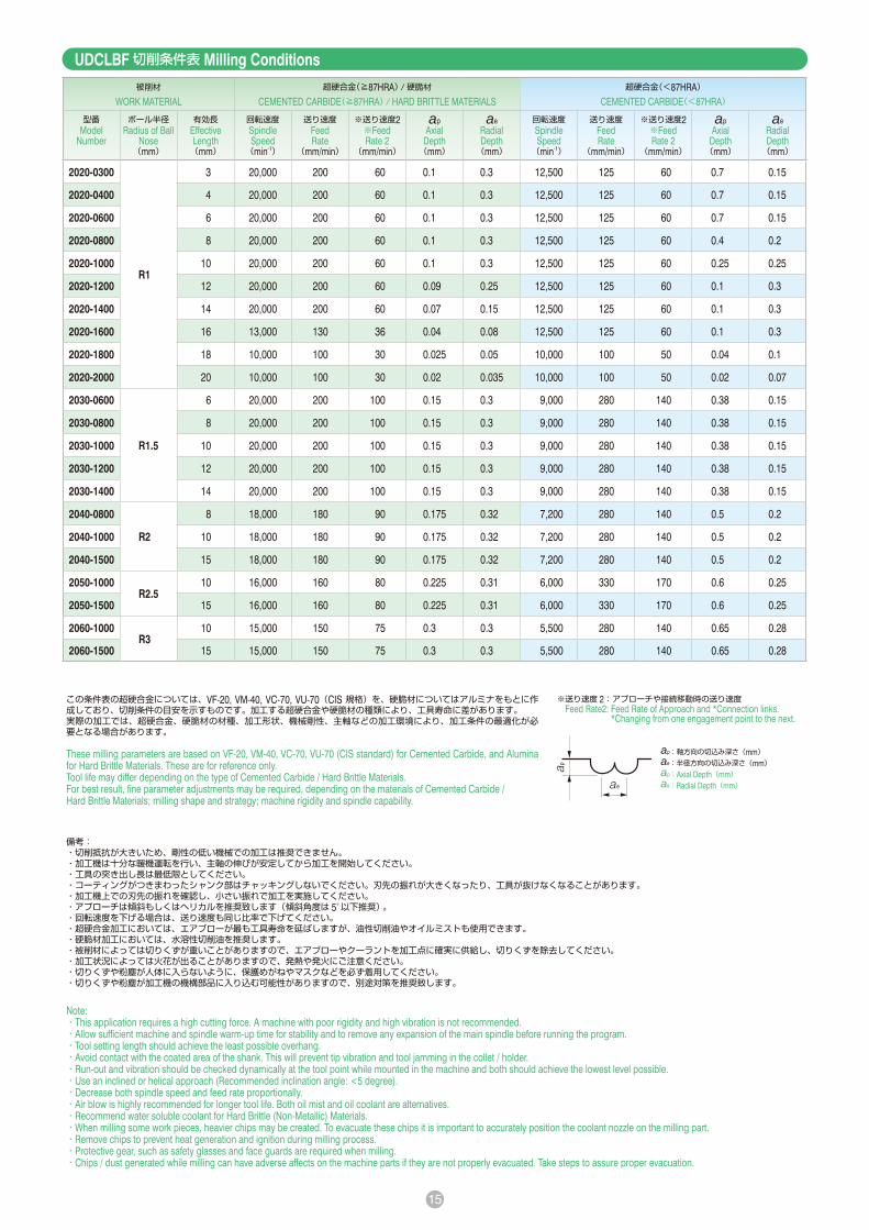
UDCLBF 切削条件表 Milling Conditions
備考:・切削抵抗が大きいため、剛性の低い機械での加工は推奨できません。・加工機は十分な暖機運転を行い、主軸の伸びが安定してから加工を開始してください。・工具の突き出し長は最低限としてください。・コーティングがつきまわったシャンク部はチャッキングしないでください。刃先の振れが大きくなったり、工具が抜けなくなることがあります。・加工機上での刃先の振れを確認し、小さい振れで加工を実施してください。・アプローチは傾斜もしくはヘリカルを推奨致します(傾斜角度は 5°以下推奨) 。・回転速度を下げる場合は、送り速度も同じ比率で下げてください。・超硬合金加工においては、エアブローが最も工具寿命を延ばしますが、油性切削油やオイルミストも使用できます。・硬脆材加工においては、水溶性切削油を推奨します。・被削材によっては切りくずが重いことがありますので、エアブローやクーラントを加工点に確実に供給し、切りくずを除去してください。・加工状況によっては火花が出ることがありますので、発熱や発火にご注意ください。・切りくずや粉塵が人体に入らないように、保護めがねやマスクなどを必ず着用してください。・切りくずや粉塵が加工機の機構部品に入り込む可能性がありますので、別途対策を推奨致します。
Note:・This application requires a high cutting force. A machine with poor rigidity and high vibration is not recommended.・Allow sufficient machine and spindle warm-up time for stability and to remove any expansion of the main spindle before running the program.・Tool setting length should achieve the least possible overhang.・Avoid contact with the coated area of the shank. This will prevent tip vibration and tool jamming in the collet / holder.・Run-out and vibration should be checked dynamically at the tool point while mounted in the machine and both should achieve the lowest level possible.・Use an inclined or helical approach (Recommended inclination angle: <5 degree).・Decrease both spindle speed and feed rate proportionally.・Air blow is highly recommended for longer tool life. Both oil mist and oil coolant are alternatives.・Recommend water soluble coolant for Hard Brittle (Non-Metallic) Materials.・When milling some work pieces, heavier chips may be created. To evacuate these chips it is important to accurately position the coolant nozzle on the milling part.・Remove chips to prevent heat generation and ignition during milling process.・Protective gear, such as safety glasses and face guards are required when milling.・Chips / dust generated while milling can have adverse affects on the machine parts if they are not properly evacuated. Take steps to assure proper evacuation.
この条件表の超硬合金については、VF-20, VM-40, VC-70, VU-70(CIS 規格)を、硬脆材についてはアルミナをもとに作成しており、切削条件の目安を示すものです。加工する超硬合金や硬脆材の種類により、工具寿命に差があります。実際の加工では、超硬合金、硬脆材の材種、加工形状、機械剛性、主軸などの加工環境により、加工条件の最適化が必要となる場合があります。
These milling parameters are based on VF-20, VM-40, VC-70, VU-70 (CIS standard) for Cemented Carbide, and Alumina for Hard Brittle Materials. These are for reference only.Tool life may differ depending on the type of Cemented Carbide / Hard Brittle Materials.For best result, fine parameter adjustments may be required, depending on the materials of Cemented Carbide / Hard Brittle Materials; milling shape and strategy; machine rigidity and spindle capability.
被削材
WORK MATERIAL超硬合金(≧87HRA)/硬脆材
CEMENTED CARBIDE(≧87HRA)/ HARD BRITTLE MATERIALS超硬合金(<87HRA)
CEMENTED CARBIDE(<87HRA)
型番Model
Number
ボール半径Radius of Ball
Nose(mm)
有効長Effective Length(mm)
回転速度Spindle Speed(min-1)
送り速度Feed Rate
(mm/min)
※送り速度2※Feed Rate 2
(mm/min)
apAxial
Depth(mm)
aeRadial Depth(mm)
回転速度Spindle Speed(min-1)
送り速度Feed Rate
(mm/min)
※送り速度2※Feed Rate 2
(mm/min)
apAxial
Depth(mm)
aeRadial Depth(mm)
2020-0300
R1
3 20,000 200 60 0.1 0.3 12,500 125 60 0.7 0.15
2020-0400 4 20,000 200 60 0.1 0.3 12,500 125 60 0.7 0.15
2020-0600 6 20,000 200 60 0.1 0.3 12,500 125 60 0.7 0.15
2020-0800 8 20,000 200 60 0.1 0.3 12,500 125 60 0.4 0.2
2020-1000 10 20,000 200 60 0.1 0.3 12,500 125 60 0.25 0.25
2020-1200 12 20,000 200 60 0.09 0.25 12,500 125 60 0.1 0.3
2020-1400 14 20,000 200 60 0.07 0.15 12,500 125 60 0.1 0.3
2020-1600 16 13,000 130 36 0.04 0.08 12,500 125 60 0.1 0.3
2020-1800 18 10,000 100 30 0.025 0.05 10,000 100 50 0.04 0.1
2020-2000 20 10,000 100 30 0.02 0.035 10,000 100 50 0.02 0.07
2030-0600
R1.5
6 20,000 200 100 0.15 0.3 9,000 280 140 0.38 0.15
2030-0800 8 20,000 200 100 0.15 0.3 9,000 280 140 0.38 0.15
2030-1000 10 20,000 200 100 0.15 0.3 9,000 280 140 0.38 0.15
2030-1200 12 20,000 200 100 0.15 0.3 9,000 280 140 0.38 0.15
2030-1400 14 20,000 200 100 0.15 0.3 9,000 280 140 0.38 0.15
2040-0800
R2
8 18,000 180 90 0.175 0.32 7,200 280 140 0.5 0.2
2040-1000 10 18,000 180 90 0.175 0.32 7,200 280 140 0.5 0.2
2040-1500 15 18,000 180 90 0.175 0.32 7,200 280 140 0.5 0.2
2050-1000R2.5
10 16,000 160 80 0.225 0.31 6,000 330 170 0.6 0.25
2050-1500 15 16,000 160 80 0.225 0.31 6,000 330 170 0.6 0.25
2060-1000R3
10 15,000 150 75 0.3 0.3 5,500 280 140 0.65 0.28
2060-1500 15 15,000 150 75 0.3 0.3 5,500 280 140 0.65 0.28
※送り速度 2 : アプローチや接続移動時の送り速度 Feed Rate2: Feed Rate of Approach and *Connection links.
*Changing from one engagement point to the next.
ap:軸方向の切込み深さ(mm)ae:半径方向の切込み深さ(mm)ap:Axial Depth(mm)ae:Radial Depth(mm)

16
UDCLRSFサイズ Size φ0.3~φ2
合計 52型番 Total 52 models 単位 Unit(mm)型番
ModelNumber
外径Outside
DiameterφD
コーナ半径ConerRadius
CR
有効長EffectiveLengthℓ1
刃長Lengthof Cutℓ
首径Neck
Diameterφd1
シャンクテーパ角Shank Taper
AngleBta
全長OverallLength
L
シャンク径Shank
Diameterφd
定価Price
¥
ワーク勾配角に対する実有効長Effective Length by
Inclined Angles
30′ 1° 1°30′ 2° 3°
UDCLRSF 2003-0030060.3
R0.03 0.60.15 0.28 16°
50 4 54,600 0.61 0.63 0.65 0.67 0.72
UDCLRSF 2003-005006 R0.05 0.6 50 4 54,600 0.61 0.63 0.65 0.67 0.72
UDCLRSF 2005-003005
0.5
R0.03
0.5
0.25 0.46 16°
50 4 52,000 0.55 0.56 0.58 0.60 0.64
UDCLRSF 2005-003010 1 50 4 52,000 1.06 1.10 1.13 1.17 1.25
※ UDCLRSF 2005-003015 1.5 50 4 52,000 1.58 1.63 1.68 1.74 1.87
UDCLRSF 2005-005005
R0.05
0.5 50 4 52,000 0.55 0.56 0.58 0.60 0.64
UDCLRSF 2005-005010 1 50 4 52,000 1.06 1.09 1.13 1.17 1.25
※ UDCLRSF 2005-005015 1.5 50 4 52,000 1.58 1.63 1.68 1.74 1.86
UDCLRSF 2008-003008
0.8
R0.03
0.8
0.4 0.76 16°
50 4 46,700 0.86 0.88 0.91 0.94 1.01
UDCLRSF 2008-003016 1.6 50 4 46,700 1.68 1.73 1.79 1.85 1.99
※ UDCLRSF 2008-003024 2.4 50 4 46,700 2.51 2.59 2.67 2.76 2.97
UDCLRSF 2008-005008
R0.05
0.8 50 4 46,700 0.85 0.88 0.91 0.94 1.01
UDCLRSF 2008-005016 1.6 50 4 46,700 1.68 1.73 1.79 1.85 1.98
※ UDCLRSF 2008-005024 2.4 50 4 46,700 2.50 2.58 2.67 2.76 2.96
UDCLRSF 2008-010008
R0.1
0.8 50 4 46,700 0.85 0.88 0.90 0.93 0.99
UDCLRSF 2008-010016 1.6 50 4 46,700 1.68 1.73 1.78 1.84 1.97
※ UDCLRSF 2008-010024 2.4 50 4 46,700 2.50 2.58 2.66 2.75 2.95
対応被削材表(☆◎○の順に推奨)Material Applications(☆ Highly Recommended ◎ Recommended ○ Suggested)被 削 材 Work Material
炭素鋼CARBONSTEELS
S45CS55C
合金鋼ALLOY
STEELSSK / SCM
SUS
プリハードン鋼PREHARDENED
STEELSNAKHPM
焼入れ鋼HARDENED STEELS
鋳鉄CAST IRON
アルミ合金ALUMINUM
ALLOYS
グラファイトGRAPHITE
銅COPPER
樹脂PLASTICS
ガラス入り樹脂GLASSFILLED
PLASTICS
チタン合金TITANIUMALLOYS
超耐熱合金HEAT
RESISTANTALLOYS
超硬合金CEMENTED
CARBIDE
硬脆材HARD BRITTLE
(NON-METALLIC)MATERIALS~ 55HRC ~ 60HRC ~ 70HRC
○ ☆ ◎※
※硬脆材:セラミックス(アルミナ、ジルコニアなど)、ガラスなど Hard Brittle (Non-Metallic) Materials: Ceramics (Alumina, Zirconia, etc.), Glasses and etc.
2 枚刃 2Flutes 超硬合金・硬脆材加工用ハイグレードロングネックラジアスエンドミル High-grade Long Neck Radius End Mills for Cemented Carbide and Hard Brittle Materials
超硬合金・硬脆材を切削できるロングネックラジアスエンドミル UDCLRS の上級バージョン。ダイヤモンドコーティングを改良し、最適な刃形状を採用することで驚異的な「深」切込みが可能となり、工具寿命も延長。切れ刃に特殊処理を施すことで、被削材のコバ欠けや段差を最大限に抑制し、中荒から仕上げ加工に幅広く適応。
Long Neck Radius End Mills for milling Cemented Carbide & Hard Brittle (Non-Metallic) Materials. Upgraded version of UDCLRS.Achieve remarkable cutting depth and longer tool life.Special cutting edge treatment helps to avoid the edge chipping & level gap on the work piece. Recommended to use on semi-roughing & finishing process.
特長 Features
シャンクテーパ角は目安です。ワークとの干渉が心配な場合は必ず実測して確認してください。シャンク部とワークの接触にご注意ください。The shank taper angle shown is not an exact value and to avoidcontact with the workpiece, we recommend the user controls theprecise value of this angle. Shank taper angle should not makecontact with the work piece.ラベルに実測の外径とコーナR精度を記載しております。
高精度加工にお役立てください。Diameter and Corner R accuracy measurements are printed on the label to support High Precision milling.
SAMPLESAMPLE
ラベルサンプル Label Sample
日本特許取得Patented in Japan
追加22型番Additional 22 Models
※追加型番 Additional model

17
2 枚刃 2Flutes 超硬合金・硬脆材加工用ハイグレードロングネックラジアスエンドミル High-grade Long Neck Radius End Mills for Cemented Carbide and Hard Brittle Materials
型番Model
Number
外径Outside
DiameterφD
コーナ半径ConerRadius
CR
有効長EffectiveLengthℓ1
刃長Lengthof Cutℓ
首径Neck
Diameterφd1
シャンクテーパ角Shank Taper
AngleBta
全長OverallLength
L
シャンク径Shank
Diameterφd
定価Price
¥
ワーク勾配角に対する実有効長Effective Length by
Inclined Angles
30′ 1° 1°30′ 2° 3°
UDCLRSF 2010-003010
1
R0.03
1
0.5 0.96 16°
50 4 46,700 1.06 1.10 1.13 1.17 1.25
UDCLRSF 2010-003020 2 50 4 46,700 2.09 2.16 2.23 2.31 2.48
※ UDCLRSF 2010-003040 4 50 4 46,700 4.16 4.29 4.43 4.59 4.93
※ UDCLRSF 2010-003060 6 50 4 46,700 6.22 6.42 6.63 6.86 7.37
UDCLRSF 2010-005010
R0.05
1 50 4 46,700 1.06 1.09 1.13 1.17 1.25
UDCLRSF 2010-005020 2 50 4 46,700 2.09 2.16 2.23 2.31 2.47
※ UDCLRSF 2010-005040 4 50 4 46,700 4.15 4.29 4.43 4.58 4.92
※ UDCLRSF 2010-005060 6 50 4 46,700 6.22 6.42 6.63 6.86 7.37
UDCLRSF 2010-010010
R0.1
1 50 4 46,700 1.06 1.09 1.12 1.16 1.24
UDCLRSF 2010-010020 2 50 4 46,700 2.09 2.16 2.22 2.30 2.46
※ UDCLRSF 2010-010040 4 50 4 46,700 4.15 4.28 4.43 4.58 4.91
※ UDCLRSF 2010-010060 6 50 4 46,700 6.22 6.41 6.63 6.85 7.36
UDCLRSF 2015-003015
1.5
R0.03 1.5
0.75 1.44 16°
50 4 46,700 1.61 1.66 1.72 1.78 1.91
UDCLRSF 2015-003030 3 50 4 46,700 3.16 3.26 3.37 3.49 3.74
UDCLRSF 2015-005015R0.05
1.5 50 4 46,700 1.61 1.66 1.72 1.78 1.90
UDCLRSF 2015-005030 3 50 4 46,700 3.16 3.26 3.37 3.48 3.74
UDCLRSF 2015-010015
R0.1
1.5 50 4 46,700 1.61 1.66 1.71 1.77 1.89
UDCLRSF 2015-010030 3 50 4 46,700 3.16 3.26 3.36 3.48 3.73
※ UDCLRSF 2015-010040 4 50 4 46,700 4.19 4.32 4.46 4.62 4.95
※ UDCLRSF 2015-010060 6 50 4 46,700 6.25 6.45 6.66 6.89 7.40
UDCLRSF 2020-003020
2
R0.03
2
1 1.9 16°
50 4 46,700 2.20 2.27 2.35 2.43 2.61
UDCLRSF 2020-003040 4 50 4 46,700 4.26 4.40 4.55 4.70 5.05
※ UDCLRSF 2020-003060 6 50 4 46,700 6.33 6.53 6.75 6.98 7.50
※ UDCLRSF 2020-003080 8 50 4 46,700 8.39 8.66 8.95 9.26 9.95
※ UDCLRSF 2020-003100 10 50 4 46,700 10.45 10.79 11.15 11.54 12.40
UDCLRSF 2020-005020
R0.05
2 50 4 46,700 2.20 2.27 2.34 2.42 2.60
UDCLRSF 2020-005040 4 50 4 46,700 4.26 4.40 4.55 4.70 5.05
※ UDCLRSF 2020-005060 6 50 4 46,700 6.33 6.53 6.75 6.98 7.50
※ UDCLRSF 2020-005080 8 50 4 46,700 8.39 8.66 8.95 9.26 9.94
※ UDCLRSF 2020-005100 10 50 4 46,700 10.45 10.79 11.15 11.53 12.39
UDCLRSF 2020-010020
R0.1
2 50 4 46,700 2.20 2.27 2.34 2.42 2.59
UDCLRSF 2020-010040 4 50 4 46,700 4.26 4.40 4.54 4.69 5.04
※ UDCLRSF 2020-010060 6 50 4 46,700 6.32 6.53 6.74 6.97 7.49
※ UDCLRSF 2020-010080 8 50 4 46,700 8.39 8.66 8.94 9.25 9.93
※ UDCLRSF 2020-010100 10 50 4 46,700 10.45 10.79 11.14 11.53 12.38
※追加型番 Additional model

18
被削材 WORK MATERIAL
超硬合金(≧87HRA)/硬脆材 CEMENTED CARBIDE(≧87HRA)/ HARD BRITTLE MATERIALS
被削材 WORK MATERIAL
超硬合金(<87HRA) CEMENTED CARBIDE(<87HRA)
型番 Model Number
回転速度 Spindle Speed (min-1)
等高線加工 Z-Level Milling 底面加工 Flat Milling 側面加工 Side Milling 溝加工 Slotting 型番 Model Number
回転速度 Spindle Speed (min-1)
等高線加工 Z-Level Milling 底面加工 Flat Milling 側面加工 Side Milling 溝加工 Slotting
送り速度 Feed Rate (mm/min)
※送り速度2 ※Feed Rate 2 (mm/min)
apAxial Depth (mm)
aeRadial Depth (mm)
送り速度 Feed Rate (mm/min)
apAxial Depth (mm)
aeRadial Depth (mm)
送り速度 Feed Rate (mm/min)
apAxial Depth (mm)
aeRadial Depth (mm)
送り速度 Feed Rate (mm/min)
apAxial Depth (mm)
送り速度 Feed Rate (mm/min)
※送り速度2 ※Feed Rate 2 (mm/min)
apAxial Depth (mm)
aeRadial Depth (mm)
送り速度 Feed Rate (mm/min)
apAxial Depth (mm)
aeRadial Depth (mm)
送り速度 Feed Rate (mm/min)
apAxial Depth (mm)
aeRadial Depth (mm)
送り速度 Feed Rate (mm/min)
apAxial Depth (mm)
2003-003006 30,000 220 50 0.015 0.200 220 0.015 0.200 110 0.075 0.006 110 0.015 2003-003006 21,000 300 50 0.015 0.200 300 0.015 0.200 200 0.075 0.003 300 0.015
2003-005006 30,000 220 50 0.020 0.200 220 0.020 0.200 110 0.075 0.006 110 0.020 2003-005006 21,000 300 50 0.020 0.200 300 0.020 0.200 200 0.075 0.003 300 0.020
2005-003005 30,000 190 90 0.020 0.400 190 0.020 0.400 180 0.250 0.010 190 0.020 2005-003005 16,000 500 160 0.020 0.400 500 0.020 0.400 800 0.250 0.005 500 0.020
2005-003010 30,000 190 90 0.020 0.400 190 0.020 0.400 180 0.125 0.010 190 0.020 2005-003010 16,000 500 160 0.020 0.400 500 0.020 0.400 400 0.125 0.005 500 0.020
2005-003015 30,000 140 65 0.015 0.300 140 0.015 0.300 130 0.125 0.007 140 0.015 2005-003015 16,000 375 120 0.014 0.300 375 0.014 0.300 300 0.125 0.005 375 0.014
2005-005005 30,000 190 125 0.020 0.400 190 0.020 0.400 180 0.250 0.010 190 0.020 2005-005005 16,000 500 160 0.025 0.400 500 0.025 0.400 800 0.250 0.005 500 0.025
2005-005010 30,000 190 125 0.020 0.400 190 0.020 0.400 180 0.125 0.010 190 0.020 2005-005010 16,000 500 160 0.025 0.400 500 0.025 0.400 400 0.125 0.005 500 0.025
2005-005015 30,000 140 65 0.015 0.300 140 0.015 0.300 130 0.125 0.007 140 0.015 2005-005015 16,000 375 120 0.017 0.300 375 0.017 0.300 300 0.125 0.005 375 0.017
2008-003008 30,000 190 90 0.020 0.600 190 0.020 0.600 300 0.400 0.016 190 0.020 2008-003008 13,000 390 130 0.020 0.600 390 0.020 0.600 1200 0.400 0.008 390 0.020
2008-003016 30,000 190 90 0.020 0.600 190 0.020 0.600 300 0.200 0.010 190 0.020 2008-003016 13,000 390 130 0.020 0.600 390 0.020 0.600 600 0.200 0.008 390 0.020
2008-003024 30,000 175 80 0.018 0.500 175 0.018 0.500 275 0.200 0.007 175 0.018 2008-003024 13,000 350 120 0.014 0.500 350 0.014 0.500 540 0.200 0.006 350 0.014
2008-005008 30,000 190 150 0.025 0.600 190 0.025 0.600 300 0.400 0.016 190 0.025 2008-005008 13,000 390 130 0.025 0.600 390 0.025 0.600 1200 0.400 0.008 390 0.025
2008-005016 30,000 190 150 0.025 0.600 190 0.025 0.600 300 0.200 0.010 190 0.025 2008-005016 13,000 390 130 0.025 0.600 390 0.025 0.600 600 0.200 0.008 390 0.025
2008-005024 30,000 175 80 0.023 0.500 175 0.023 0.500 275 0.200 0.007 175 0.023 2008-005024 13,000 350 120 0.017 0.500 350 0.017 0.500 540 0.200 0.006 350 0.017
2008-010008 30,000 190 150 0.030 0.600 190 0.030 0.600 300 0.400 0.016 190 0.030 2008-010008 13,000 390 130 0.030 0.600 390 0.030 0.600 1200 0.400 0.008 390 0.030
2008-010016 30,000 190 150 0.030 0.600 190 0.030 0.600 300 0.200 0.010 190 0.030 2008-010016 13,000 390 130 0.030 0.600 390 0.030 0.600 600 0.200 0.008 390 0.030
2008-010024 30,000 175 80 0.028 0.500 175 0.028 0.500 275 0.200 0.007 175 0.028 2008-010024 13,000 350 120 0.020 0.500 350 0.020 0.500 540 0.200 0.006 350 0.020
2010-003010 30,000 190 90 0.020 0.800 190 0.020 0.800 375 0.500 0.020 190 0.020 2010-003010 12,000 360 120 0.020 0.800 360 0.020 0.800 1440 0.500 0.010 360 0.020
2010-003020 30,000 190 90 0.020 0.800 190 0.020 0.800 375 0.250 0.010 190 0.020 2010-003020 12,000 360 120 0.020 0.800 360 0.020 0.800 720 0.250 0.010 360 0.020
2010-003040 30,000 190 90 0.016 0.600 190 0.016 0.600 375 0.250 0.005 190 0.016 2010-003040 10,000 300 100 0.012 0.700 300 0.012 0.700 600 0.250 0.008 300 0.012
2010-003060 25,000 155 75 0.010 0.500 155 0.010 0.500 300 0.250 0.005 155 0.010 2010-003060 10,000 300 100 0.008 0.700 300 0.008 0.700 600 0.250 0.006 300 0.008
2010-005010 30,000 190 185 0.025 0.800 190 0.025 0.800 375 0.500 0.020 190 0.025 2010-005010 12,000 360 120 0.025 0.800 360 0.025 0.800 1440 0.500 0.010 360 0.025
2010-005020 30,000 190 185 0.025 0.800 190 0.025 0.800 375 0.250 0.010 190 0.025 2010-005020 12,000 360 120 0.025 0.800 360 0.025 0.800 720 0.250 0.010 360 0.025
2010-005040 30,000 190 185 0.020 0.600 190 0.020 0.600 375 0.250 0.005 190 0.020 2010-005040 10,000 300 100 0.015 0.700 300 0.015 0.700 600 0.250 0.008 300 0.015
2010-005060 25,000 155 150 0.012 0.500 155 0.012 0.500 300 0.250 0.005 155 0.012 2010-005060 10,000 300 100 0.010 0.700 300 0.010 0.700 600 0.250 0.006 300 0.010
2010-010010 30,000 190 185 0.030 0.800 190 0.030 0.800 375 0.500 0.020 190 0.030 2010-010010 12,000 360 120 0.030 0.800 360 0.030 0.800 1440 0.500 0.010 360 0.030
2010-010020 30,000 190 185 0.030 0.800 190 0.030 0.800 375 0.250 0.010 190 0.030 2010-010020 12,000 360 120 0.030 0.800 360 0.030 0.800 720 0.250 0.010 360 0.030
2010-010040 30,000 190 185 0.025 0.600 190 0.025 0.600 375 0.250 0.005 190 0.025 2010-010040 10,000 300 100 0.020 0.700 300 0.020 0.700 600 0.250 0.008 300 0.020
2010-010060 25,000 155 150 0.015 0.500 155 0.015 0.500 300 0.250 0.005 155 0.015 2010-010060 10,000 300 100 0.012 0.700 300 0.012 0.700 600 0.250 0.006 300 0.012
2015-003015 25,000 190 90 0.030 1.300 190 0.030 1.300 375 0.750 0.020 190 0.030 2015-003015 11,000 330 110 0.030 1.300 330 0.030 1.300 1440 0.750 0.010 330 0.030
2015-003030 25,000 190 90 0.030 1.300 190 0.030 1.300 375 0.375 0.010 190 0.030 2015-003030 11,000 330 110 0.030 1.300 330 0.030 1.300 720 0.375 0.010 330 0.030
2015-005015 25,000 190 125 0.040 1.300 190 0.040 1.300 375 0.750 0.020 190 0.040 2015-005015 11,000 330 110 0.040 1.300 330 0.040 1.300 1440 0.750 0.010 330 0.040
2015-005030 25,000 190 125 0.040 1.300 190 0.040 1.300 375 0.375 0.010 190 0.040 2015-005030 11,000 330 110 0.040 1.300 330 0.040 1.300 720 0.375 0.010 330 0.040
2015-010015 25,000 190 150 0.045 1.300 190 0.045 1.300 375 0.750 0.020 190 0.045 2015-010015 11,000 330 110 0.045 1.300 330 0.045 1.300 1440 0.750 0.010 330 0.045
2015-010030 25,000 190 150 0.045 1.300 190 0.045 1.300 375 0.375 0.010 190 0.045 2015-010030 11,000 330 110 0.045 1.300 330 0.045 1.300 720 0.375 0.010 330 0.045
2015-010040 25,000 190 150 0.043 1.200 190 0.043 1.200 350 0.375 0.008 190 0.043 2015-010040 11,000 330 110 0.045 1.100 330 0.045 1.100 720 0.375 0.010 330 0.045
2015-010060 25,000 190 150 0.040 1.000 190 0.040 1.000 350 0.375 0.005 190 0.040 2015-010060 11,000 330 110 0.030 1.100 330 0.030 1.100 720 0.375 0.009 330 0.030
UDCLRSF 切削条件表 Milling Conditions UDCLRSF の備考は、P22 に記載しております。Refer to page 22 for UDCLRSF note.

19
被削材 WORK MATERIAL
超硬合金(≧87HRA)/硬脆材 CEMENTED CARBIDE(≧87HRA)/ HARD BRITTLE MATERIALS
被削材 WORK MATERIAL
超硬合金(<87HRA) CEMENTED CARBIDE(<87HRA)
型番 Model Number
回転速度 Spindle Speed (min-1)
等高線加工 Z-Level Milling 底面加工 Flat Milling 側面加工 Side Milling 溝加工 Slotting 型番 Model Number
回転速度 Spindle Speed (min-1)
等高線加工 Z-Level Milling 底面加工 Flat Milling 側面加工 Side Milling 溝加工 Slotting
送り速度 Feed Rate (mm/min)
※送り速度2 ※Feed Rate 2 (mm/min)
apAxial Depth (mm)
aeRadial Depth (mm)
送り速度 Feed Rate (mm/min)
apAxial Depth (mm)
aeRadial Depth (mm)
送り速度 Feed Rate (mm/min)
apAxial Depth (mm)
aeRadial Depth (mm)
送り速度 Feed Rate (mm/min)
apAxial Depth (mm)
送り速度 Feed Rate (mm/min)
※送り速度2 ※Feed Rate 2 (mm/min)
apAxial Depth (mm)
aeRadial Depth (mm)
送り速度 Feed Rate (mm/min)
apAxial Depth (mm)
aeRadial Depth (mm)
送り速度 Feed Rate (mm/min)
apAxial Depth (mm)
aeRadial Depth (mm)
送り速度 Feed Rate (mm/min)
apAxial Depth (mm)
2003-003006 30,000 220 50 0.015 0.200 220 0.015 0.200 110 0.075 0.006 110 0.015 2003-003006 21,000 300 50 0.015 0.200 300 0.015 0.200 200 0.075 0.003 300 0.015
2003-005006 30,000 220 50 0.020 0.200 220 0.020 0.200 110 0.075 0.006 110 0.020 2003-005006 21,000 300 50 0.020 0.200 300 0.020 0.200 200 0.075 0.003 300 0.020
2005-003005 30,000 190 90 0.020 0.400 190 0.020 0.400 180 0.250 0.010 190 0.020 2005-003005 16,000 500 160 0.020 0.400 500 0.020 0.400 800 0.250 0.005 500 0.020
2005-003010 30,000 190 90 0.020 0.400 190 0.020 0.400 180 0.125 0.010 190 0.020 2005-003010 16,000 500 160 0.020 0.400 500 0.020 0.400 400 0.125 0.005 500 0.020
2005-003015 30,000 140 65 0.015 0.300 140 0.015 0.300 130 0.125 0.007 140 0.015 2005-003015 16,000 375 120 0.014 0.300 375 0.014 0.300 300 0.125 0.005 375 0.014
2005-005005 30,000 190 125 0.020 0.400 190 0.020 0.400 180 0.250 0.010 190 0.020 2005-005005 16,000 500 160 0.025 0.400 500 0.025 0.400 800 0.250 0.005 500 0.025
2005-005010 30,000 190 125 0.020 0.400 190 0.020 0.400 180 0.125 0.010 190 0.020 2005-005010 16,000 500 160 0.025 0.400 500 0.025 0.400 400 0.125 0.005 500 0.025
2005-005015 30,000 140 65 0.015 0.300 140 0.015 0.300 130 0.125 0.007 140 0.015 2005-005015 16,000 375 120 0.017 0.300 375 0.017 0.300 300 0.125 0.005 375 0.017
2008-003008 30,000 190 90 0.020 0.600 190 0.020 0.600 300 0.400 0.016 190 0.020 2008-003008 13,000 390 130 0.020 0.600 390 0.020 0.600 1200 0.400 0.008 390 0.020
2008-003016 30,000 190 90 0.020 0.600 190 0.020 0.600 300 0.200 0.010 190 0.020 2008-003016 13,000 390 130 0.020 0.600 390 0.020 0.600 600 0.200 0.008 390 0.020
2008-003024 30,000 175 80 0.018 0.500 175 0.018 0.500 275 0.200 0.007 175 0.018 2008-003024 13,000 350 120 0.014 0.500 350 0.014 0.500 540 0.200 0.006 350 0.014
2008-005008 30,000 190 150 0.025 0.600 190 0.025 0.600 300 0.400 0.016 190 0.025 2008-005008 13,000 390 130 0.025 0.600 390 0.025 0.600 1200 0.400 0.008 390 0.025
2008-005016 30,000 190 150 0.025 0.600 190 0.025 0.600 300 0.200 0.010 190 0.025 2008-005016 13,000 390 130 0.025 0.600 390 0.025 0.600 600 0.200 0.008 390 0.025
2008-005024 30,000 175 80 0.023 0.500 175 0.023 0.500 275 0.200 0.007 175 0.023 2008-005024 13,000 350 120 0.017 0.500 350 0.017 0.500 540 0.200 0.006 350 0.017
2008-010008 30,000 190 150 0.030 0.600 190 0.030 0.600 300 0.400 0.016 190 0.030 2008-010008 13,000 390 130 0.030 0.600 390 0.030 0.600 1200 0.400 0.008 390 0.030
2008-010016 30,000 190 150 0.030 0.600 190 0.030 0.600 300 0.200 0.010 190 0.030 2008-010016 13,000 390 130 0.030 0.600 390 0.030 0.600 600 0.200 0.008 390 0.030
2008-010024 30,000 175 80 0.028 0.500 175 0.028 0.500 275 0.200 0.007 175 0.028 2008-010024 13,000 350 120 0.020 0.500 350 0.020 0.500 540 0.200 0.006 350 0.020
2010-003010 30,000 190 90 0.020 0.800 190 0.020 0.800 375 0.500 0.020 190 0.020 2010-003010 12,000 360 120 0.020 0.800 360 0.020 0.800 1440 0.500 0.010 360 0.020
2010-003020 30,000 190 90 0.020 0.800 190 0.020 0.800 375 0.250 0.010 190 0.020 2010-003020 12,000 360 120 0.020 0.800 360 0.020 0.800 720 0.250 0.010 360 0.020
2010-003040 30,000 190 90 0.016 0.600 190 0.016 0.600 375 0.250 0.005 190 0.016 2010-003040 10,000 300 100 0.012 0.700 300 0.012 0.700 600 0.250 0.008 300 0.012
2010-003060 25,000 155 75 0.010 0.500 155 0.010 0.500 300 0.250 0.005 155 0.010 2010-003060 10,000 300 100 0.008 0.700 300 0.008 0.700 600 0.250 0.006 300 0.008
2010-005010 30,000 190 185 0.025 0.800 190 0.025 0.800 375 0.500 0.020 190 0.025 2010-005010 12,000 360 120 0.025 0.800 360 0.025 0.800 1440 0.500 0.010 360 0.025
2010-005020 30,000 190 185 0.025 0.800 190 0.025 0.800 375 0.250 0.010 190 0.025 2010-005020 12,000 360 120 0.025 0.800 360 0.025 0.800 720 0.250 0.010 360 0.025
2010-005040 30,000 190 185 0.020 0.600 190 0.020 0.600 375 0.250 0.005 190 0.020 2010-005040 10,000 300 100 0.015 0.700 300 0.015 0.700 600 0.250 0.008 300 0.015
2010-005060 25,000 155 150 0.012 0.500 155 0.012 0.500 300 0.250 0.005 155 0.012 2010-005060 10,000 300 100 0.010 0.700 300 0.010 0.700 600 0.250 0.006 300 0.010
2010-010010 30,000 190 185 0.030 0.800 190 0.030 0.800 375 0.500 0.020 190 0.030 2010-010010 12,000 360 120 0.030 0.800 360 0.030 0.800 1440 0.500 0.010 360 0.030
2010-010020 30,000 190 185 0.030 0.800 190 0.030 0.800 375 0.250 0.010 190 0.030 2010-010020 12,000 360 120 0.030 0.800 360 0.030 0.800 720 0.250 0.010 360 0.030
2010-010040 30,000 190 185 0.025 0.600 190 0.025 0.600 375 0.250 0.005 190 0.025 2010-010040 10,000 300 100 0.020 0.700 300 0.020 0.700 600 0.250 0.008 300 0.020
2010-010060 25,000 155 150 0.015 0.500 155 0.015 0.500 300 0.250 0.005 155 0.015 2010-010060 10,000 300 100 0.012 0.700 300 0.012 0.700 600 0.250 0.006 300 0.012
2015-003015 25,000 190 90 0.030 1.300 190 0.030 1.300 375 0.750 0.020 190 0.030 2015-003015 11,000 330 110 0.030 1.300 330 0.030 1.300 1440 0.750 0.010 330 0.030
2015-003030 25,000 190 90 0.030 1.300 190 0.030 1.300 375 0.375 0.010 190 0.030 2015-003030 11,000 330 110 0.030 1.300 330 0.030 1.300 720 0.375 0.010 330 0.030
2015-005015 25,000 190 125 0.040 1.300 190 0.040 1.300 375 0.750 0.020 190 0.040 2015-005015 11,000 330 110 0.040 1.300 330 0.040 1.300 1440 0.750 0.010 330 0.040
2015-005030 25,000 190 125 0.040 1.300 190 0.040 1.300 375 0.375 0.010 190 0.040 2015-005030 11,000 330 110 0.040 1.300 330 0.040 1.300 720 0.375 0.010 330 0.040
2015-010015 25,000 190 150 0.045 1.300 190 0.045 1.300 375 0.750 0.020 190 0.045 2015-010015 11,000 330 110 0.045 1.300 330 0.045 1.300 1440 0.750 0.010 330 0.045
2015-010030 25,000 190 150 0.045 1.300 190 0.045 1.300 375 0.375 0.010 190 0.045 2015-010030 11,000 330 110 0.045 1.300 330 0.045 1.300 720 0.375 0.010 330 0.045
2015-010040 25,000 190 150 0.043 1.200 190 0.043 1.200 350 0.375 0.008 190 0.043 2015-010040 11,000 330 110 0.045 1.100 330 0.045 1.100 720 0.375 0.010 330 0.045
2015-010060 25,000 190 150 0.040 1.000 190 0.040 1.000 350 0.375 0.005 190 0.040 2015-010060 11,000 330 110 0.030 1.100 330 0.030 1.100 720 0.375 0.009 330 0.030
UDCLRSF 切削条件表 Milling Conditions UDCLRSF の備考は、P22 に記載しております。Refer to page 22 for UDCLRSF note.

20
被削材 WORK MATERIAL
超硬合金(≧87HRA)/硬脆材 CEMENTED CARBIDE(≧87HRA)/ HARD BRITTLE MATERIALS
被削材 WORK MATERIAL
超硬合金(<87HRA) CEMENTED CARBIDE(<87HRA)
型番 Model Number
回転速度 Spindle Speed (min-1)
等高線加工 Z-Level Milling 底面加工 Flat Milling 側面加工 Side Milling 溝加工 Slotting 型番 Model Number
回転速度 Spindle Speed (min-1)
等高線加工 Z-Level Milling 底面加工 Flat Milling 側面加工 Side Milling 溝加工 Slotting
送り速度 Feed Rate (mm/min)
※送り速度2 ※Feed Rate 2 (mm/min)
apAxial Depth (mm)
aeRadial Depth (mm)
送り速度 Feed Rate (mm/min)
apAxial Depth (mm)
aeRadial Depth (mm)
送り速度 Feed Rate (mm/min)
apAxial Depth (mm)
aeRadial Depth (mm)
送り速度 Feed Rate (mm/min)
apAxial Depth (mm)
送り速度 Feed Rate (mm/min)
※送り速度2 ※Feed Rate 2 (mm/min)
apAxial Depth (mm)
aeRadial Depth (mm)
送り速度 Feed Rate (mm/min)
apAxial Depth (mm)
aeRadial Depth (mm)
送り速度 Feed Rate (mm/min)
apAxial Depth (mm)
aeRadial Depth (mm)
送り速度 Feed Rate (mm/min)
apAxial Depth (mm)
2020-003020 20,000 190 90 0.040 1.800 190 0.040 1.800 375 1.000 0.020 190 0.040 2020-003020 10,000 300 100 0.040 1.800 300 0.040 1.800 1440 1.000 0.010 300 0.040
2020-003040 20,000 190 90 0.040 1.800 190 0.040 1.800 375 0.500 0.010 190 0.040 2020-003040 10,000 300 100 0.040 1.800 300 0.040 1.800 1440 1.000 0.010 300 0.040
2020-003060 20,000 190 90 0.037 1.700 190 0.037 1.700 325 0.500 0.007 190 0.037 2020-003060 10,000 300 100 0.036 1.600 300 0.036 1.600 1440 0.500 0.010 300 0.036
2020-003080 20,000 190 90 0.030 1.500 190 0.030 1.500 325 0.500 0.005 190 0.030 2020-003080 10,000 300 100 0.023 1.600 300 0.023 1.600 1440 0.500 0.009 300 0.023
2020-003100 20,000 190 90 0.025 1.300 190 0.025 1.300 300 0.500 0.005 190 0.025 2020-003100 10,000 300 100 0.018 1.600 300 0.018 1.600 1440 0.500 0.009 300 0.018
2020-005020 20,000 190 90 0.050 1.800 190 0.050 1.800 375 1.000 0.020 190 0.050 2020-005020 10,000 300 100 0.050 1.800 300 0.050 1.800 1440 1.000 0.010 300 0.050
2020-005040 20,000 190 90 0.050 1.800 190 0.050 1.800 375 0.500 0.010 190 0.050 2020-005040 10,000 300 100 0.050 1.800 300 0.050 1.800 1440 1.000 0.010 300 0.050
2020-005060 20,000 190 90 0.045 1.700 190 0.045 1.700 325 0.500 0.007 190 0.045 2020-005060 10,000 300 100 0.045 1.600 300 0.045 1.600 1440 0.500 0.010 300 0.045
2020-005080 20,000 190 90 0.040 1.500 190 0.040 1.500 325 0.500 0.005 190 0.040 2020-005080 10,000 300 100 0.028 1.600 300 0.028 1.600 1440 0.500 0.009 300 0.028
2020-005100 20,000 190 90 0.028 1.300 190 0.028 1.300 300 0.500 0.005 190 0.028 2020-005100 10,000 300 100 0.020 1.600 300 0.020 1.600 1440 0.500 0.009 300 0.020
2020-010020 20,000 190 125 0.060 1.800 190 0.060 1.800 375 1.000 0.020 190 0.060 2020-010020 10,000 300 100 0.060 1.800 300 0.060 1.800 1440 1.000 0.010 300 0.060
2020-010040 20,000 190 125 0.060 1.800 190 0.060 1.800 375 0.500 0.010 190 0.060 2020-010040 10,000 300 100 0.060 1.800 300 0.060 1.800 1440 1.000 0.010 300 0.060
2020-010060 20,000 190 125 0.055 1.700 190 0.055 1.700 325 0.500 0.007 190 0.055 2020-010060 10,000 300 100 0.054 1.600 300 0.054 1.600 1440 0.500 0.010 300 0.054
2020-010080 20,000 190 125 0.045 1.500 190 0.045 1.500 325 0.500 0.005 190 0.045 2020-010080 10,000 300 100 0.034 1.600 300 0.034 1.600 1440 0.500 0.009 300 0.034
2020-010100 20,000 190 125 0.033 1.300 190 0.033 1.300 300 0.500 0.005 190 0.033 2020-010100 10,000 300 100 0.023 1.600 300 0.023 1.600 1440 0.500 0.009 300 0.023
UDCLRSF 切削条件表 Milling Conditions UDCLRSF の備考は、P22 に記載しております。Refer to page 22 for UDCLRSF note.
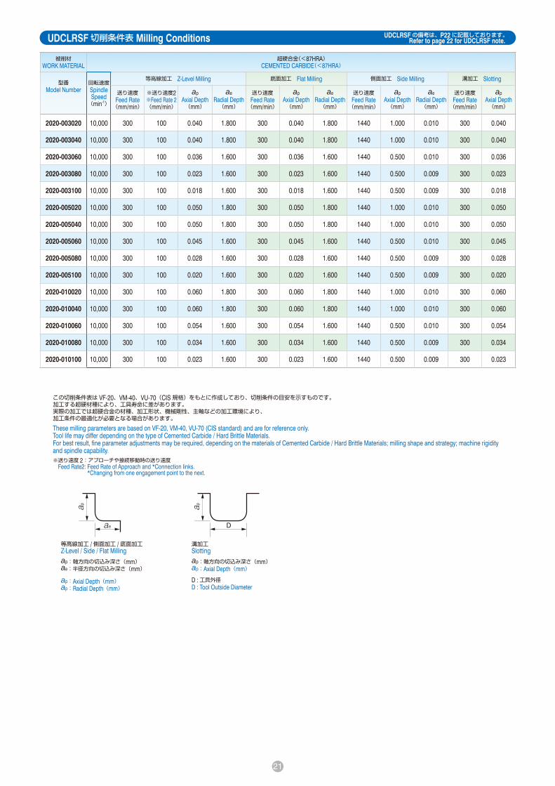
21
被削材 WORK MATERIAL
超硬合金(≧87HRA)/硬脆材 CEMENTED CARBIDE(≧87HRA)/ HARD BRITTLE MATERIALS
被削材 WORK MATERIAL
超硬合金(<87HRA) CEMENTED CARBIDE(<87HRA)
型番 Model Number
回転速度 Spindle Speed (min-1)
等高線加工 Z-Level Milling 底面加工 Flat Milling 側面加工 Side Milling 溝加工 Slotting 型番 Model Number
回転速度 Spindle Speed (min-1)
等高線加工 Z-Level Milling 底面加工 Flat Milling 側面加工 Side Milling 溝加工 Slotting
送り速度 Feed Rate (mm/min)
※送り速度2 ※Feed Rate 2 (mm/min)
apAxial Depth (mm)
aeRadial Depth (mm)
送り速度 Feed Rate (mm/min)
apAxial Depth (mm)
aeRadial Depth (mm)
送り速度 Feed Rate (mm/min)
apAxial Depth (mm)
aeRadial Depth (mm)
送り速度 Feed Rate (mm/min)
apAxial Depth (mm)
送り速度 Feed Rate (mm/min)
※送り速度2 ※Feed Rate 2 (mm/min)
apAxial Depth (mm)
aeRadial Depth (mm)
送り速度 Feed Rate (mm/min)
apAxial Depth (mm)
aeRadial Depth (mm)
送り速度 Feed Rate (mm/min)
apAxial Depth (mm)
aeRadial Depth (mm)
送り速度 Feed Rate (mm/min)
apAxial Depth (mm)
2020-003020 20,000 190 90 0.040 1.800 190 0.040 1.800 375 1.000 0.020 190 0.040 2020-003020 10,000 300 100 0.040 1.800 300 0.040 1.800 1440 1.000 0.010 300 0.040
2020-003040 20,000 190 90 0.040 1.800 190 0.040 1.800 375 0.500 0.010 190 0.040 2020-003040 10,000 300 100 0.040 1.800 300 0.040 1.800 1440 1.000 0.010 300 0.040
2020-003060 20,000 190 90 0.037 1.700 190 0.037 1.700 325 0.500 0.007 190 0.037 2020-003060 10,000 300 100 0.036 1.600 300 0.036 1.600 1440 0.500 0.010 300 0.036
2020-003080 20,000 190 90 0.030 1.500 190 0.030 1.500 325 0.500 0.005 190 0.030 2020-003080 10,000 300 100 0.023 1.600 300 0.023 1.600 1440 0.500 0.009 300 0.023
2020-003100 20,000 190 90 0.025 1.300 190 0.025 1.300 300 0.500 0.005 190 0.025 2020-003100 10,000 300 100 0.018 1.600 300 0.018 1.600 1440 0.500 0.009 300 0.018
2020-005020 20,000 190 90 0.050 1.800 190 0.050 1.800 375 1.000 0.020 190 0.050 2020-005020 10,000 300 100 0.050 1.800 300 0.050 1.800 1440 1.000 0.010 300 0.050
2020-005040 20,000 190 90 0.050 1.800 190 0.050 1.800 375 0.500 0.010 190 0.050 2020-005040 10,000 300 100 0.050 1.800 300 0.050 1.800 1440 1.000 0.010 300 0.050
2020-005060 20,000 190 90 0.045 1.700 190 0.045 1.700 325 0.500 0.007 190 0.045 2020-005060 10,000 300 100 0.045 1.600 300 0.045 1.600 1440 0.500 0.010 300 0.045
2020-005080 20,000 190 90 0.040 1.500 190 0.040 1.500 325 0.500 0.005 190 0.040 2020-005080 10,000 300 100 0.028 1.600 300 0.028 1.600 1440 0.500 0.009 300 0.028
2020-005100 20,000 190 90 0.028 1.300 190 0.028 1.300 300 0.500 0.005 190 0.028 2020-005100 10,000 300 100 0.020 1.600 300 0.020 1.600 1440 0.500 0.009 300 0.020
2020-010020 20,000 190 125 0.060 1.800 190 0.060 1.800 375 1.000 0.020 190 0.060 2020-010020 10,000 300 100 0.060 1.800 300 0.060 1.800 1440 1.000 0.010 300 0.060
2020-010040 20,000 190 125 0.060 1.800 190 0.060 1.800 375 0.500 0.010 190 0.060 2020-010040 10,000 300 100 0.060 1.800 300 0.060 1.800 1440 1.000 0.010 300 0.060
2020-010060 20,000 190 125 0.055 1.700 190 0.055 1.700 325 0.500 0.007 190 0.055 2020-010060 10,000 300 100 0.054 1.600 300 0.054 1.600 1440 0.500 0.010 300 0.054
2020-010080 20,000 190 125 0.045 1.500 190 0.045 1.500 325 0.500 0.005 190 0.045 2020-010080 10,000 300 100 0.034 1.600 300 0.034 1.600 1440 0.500 0.009 300 0.034
2020-010100 20,000 190 125 0.033 1.300 190 0.033 1.300 300 0.500 0.005 190 0.033 2020-010100 10,000 300 100 0.023 1.600 300 0.023 1.600 1440 0.500 0.009 300 0.023
等高線加工 /側面加工 /底面加工Z-Level / Side / Flat Millingap:軸方向の切込み深さ(mm)ae:半径方向の切込み深さ(mm)
ap:Axial Depth(mm)ap:Radial Depth(mm)
溝加工Slottingap:軸方向の切込み深さ(mm)ap:Axial Depth(mm)
D :工具外径D : Tool Outside Diameter
この切削条件表は VF-20、VM-40、VU-70(CIS 規格)をもとに作成しており、切削条件の目安を示すものです。加工する超硬材種により、工具寿命に差があります。実際の加工では超硬合金の材種、加工形状、機械剛性、主軸などの加工環境により、加工条件の最適化が必要となる場合があります。
These milling parameters are based on VF-20, VM-40, VU-70 (CIS standard) and are for reference only.Tool life may differ depending on the type of Cemented Carbide / Hard Brittle Materials.For best result, fine parameter adjustments may be required, depending on the materials of Cemented Carbide / Hard Brittle Materials; milling shape and strategy; machine rigidity and spindle capability. ※送り速度 2 : アプローチや接続移動時の送り速度 Feed Rate2: Feed Rate of Approach and *Connection links.
*Changing from one engagement point to the next.
UDCLRSF 切削条件表 Milling Conditions UDCLRSF の備考は、P22 に記載しております。Refer to page 22 for UDCLRSF note.

22
備考:・切削抵抗が大きいため、剛性の低い機械での加工は推奨できません。・加工機は十分な暖機運転を行い、主軸の伸びが安定してから加工を開始してください。・工具の突き出し長は最低限としてください。・コーティングがつきまわったシャンク部はチャッキングしないでください。刃先の振れが大きくなったり、工具が抜けなくなることがあります。・加工機上での刃先の振れを確認し、小さい振れで加工を実施してください。・側面加工、溝加工のアプローチは、減速する必要はありません。・等高線加工のアプローチは、傾斜もしくはヘリカルを推奨致します(傾斜角度は 1°以下推奨)。・側面加工、底面加工においては、コーナ R部の取り残し分を考慮した ap、ae を設定してください。・回転速度を下げる場合は、送り速度も同じ比率で下げてください。・超硬合金加工においては、エアブローが最も工具寿命を延ばしますが、油性切削油やオイルミストも使用できます。・硬脆材加工においては、水溶性切削油を推奨します。・被削材によっては切りくずが重いことがありますので、エアブローやクーラントを加工点に確実に供給し、切りくずを除去してください。・加工状況によっては火花が出ることがありますので、発熱や発火にご注意ください。・切りくずや粉塵が人体に入らないように、保護めがねやマスクなどを必ず着用してください。・切りくずや粉塵が加工機の機構部品に入り込む可能性がありますので、別途対策を推奨致します。
Note:・This application requires a high cutting force. A machine with poor rigidity and high vibration is not recommended.・Allow sufficient machine and spindle warm-up time for stability and to remove any expansion of the main spindle before running the program.・Tool setting length should achieve the least possible overhang.・Avoid contact with the coated area of the shank. This will prevent tip vibration and tool jamming in the collet / holder.・Run-out and vibration should be checked dynamically at the tool point while mounted in the machine and both should achieve the lowest level possible.・Does not require to be slowed down in the approach sequence when slotting and side milling.・Use an inclined or helical approach when Z-level milling (Recommended inclination angle: <1 degree).・For flat and side milling, set the axial depth (ap) and radial depth (ae) to allow for the uncut material of the corner radius.・Decrease both spindle speed and feed rate proportionally.・Air blow is highly recommended for longer tool life. Both oil mist and oil coolant are alternatives.・Recommend water soluble coolant for Hard Brittle (Non-Metallic) Materials.・When milling some work pieces, heavier chips may be created. To evacuate these chips it is important to accurately position the coolant nozzle on the milling part.・Remove chips to prevent heat generation and ignition during milling process.・Protective gear, such as safety glasses and face guards are required when milling.・Chips / dust generated while milling can have adverse affects on the machine parts if they are not properly evacuated. Take steps to assure proper evacuation.
UDCLRSF 備考 Note

23
使用工具Tool UDCLRS 2020-010-020 UDCLRSF 2020-010020
回転速度Spindle Speed 20,000 min-1
送り速度Feed Rate 375 mm/min 190 mm/min
軸方向切込み深さ apAxial Depth 0.02 mm 0.06 mm
クーラントCoolant
ノズルエアブローNozzle Air Blow
加工時間(一溝当り)Cycle Time(Per slot) 9 min 4 sec 5 min 36 sec
使用工具Tool
UDCLRS 2020-003-020UDCLRSF 2020-003020
回転速度Spindle Speed 20,000 min-1
送り速度Feed Rate 100 mm/min
軸方向切込み深さ apAxial Depth 0.01 mm
径方向切り込み深さ aeRadial Depth 0.01 mm
クーラントCoolant オイルミスト Oil Mist
加工時間Cycle Time 137 min
UDCLRS UDCLRSF
4溝加工後After 4 slots
5溝加工後After 5 slots
4溝加工後After 4 slots
5溝加工後After 5 slots
サイズ Size :20× 20× 10 mm溝サイズ Slot Size:幅Width 2× 深さ Depth 1.99 mm
超硬合金 曲線溝加工事例 UDCLRSF φ 2 × CR0.1 × 2 VM-40(90HRA)Cemented Carbide Curve Slotting Milling Example
超硬合金 底面加工事例 UDCLRSF φ 2 × CR0.03 × 2 VM-40(90HRA) Cemented Carbide Bottom Surface Milling Example
従来品より高能率・長寿命!Higher efficiency and longer tool life!
コバ欠けの抑制Minimizing Edge Chipping
加工ワーク
Wor
k M
ater
ial
工具底刃逃げ面
Rake
Fac
e工具すくい面
Relie
f
352
440
UDCLRS UDCLRSF0
2
4
6
8
10
12
14
0
100
200
300
400
500
一溝当りの加工時間
min
Cycl
e Ti
me
Per S
lot
除去体積
mm
3
Mat
eria
l Rem
oval
Vol
ume
除去体積 Material Removal Volume一溝当りの加工時間 Cycle Time Per Slot
コーナーR部損傷Corner Radius Damage
継続使用可能More tool life left
0.055
0.027
0.013 0.010
0.000
0.020
0.040
0.060
コバ欠け幅最大値
mm
Max
imum
Edg
e Ch
ippi
ng W
idth
UDCLRS UDCLRSF
入り側Entry
入り側Entry
抜け側Exit
抜け側Exit
加工方向
Milling Dire
ction
入り側観察部Entry Side
10 m
m
抜け側観察部Exit Side
加工方向Milling Direction
被削材のコバ欠け比較Edge Chipping Comparison on Work Material
コバ欠け幅 Edge Chipping Width
入り側観察部Entry Side
抜け側観察部Exit Side
UDCLRS UDCLRSF
ワーク端部Edge of work
100 μm
被削材加工面 Milling Surface
被削材加工面 Milling Surface
100 μm

24
UDCBサイズ Size R0.1~R3
超硬合金・硬脆材加工用ボールエンドミル。超硬合金加工向けダイヤモンドコーティングの開発により、抜群の硬さと靱性、密着力を実現。最適な刃形状を採用し、驚異的な「深」切り込みが可能。特に中荒から仕上げ加工において、むしれの無い良好な加工面。
Ball type End Mills for milling Cemented Carbide and Hard Brittle (Non-Metallic) Materials.Developed to give improved hardness and durability, new Diamond coating also has outstanding adhesion to the cutting tool.Achieve remarkable cutting depth with optimum tool geometry.Leaves a burr and pit free surface finish on semi-roughing & finishing process.
特長 Features
シャンクテーパ角は目安です。ワークとの干渉が心配な場合は必ず実測して確認してください。シャンク部とワークの接触にご注意ください。
The shank taper angle shown is not an exact value and to avoid contact with the workpiece, we recommend the user controls the precise value of this angle. Shank taper angle should not make contact with the work piece.
合計 14型番 Total 14 models 単位 Unit(mm)
型番Model
Number
ボール半径Radius ofBall Nose
R
刃長Lengthof Cut
ℓ
シャンクテーパ角Shank Taper
Angle
Bta
全長OverallLength
L
シャンク径Shank
Diameter
φd
定価Price
¥
UDCB 2002-0014 R0.1 0.14 16° 50 4 39,160
UDCB 2003-0021 R0.15 0.21 16° 50 4 39,160
UDCB 2004-0028 R0.2 0.28 16° 50 4 35,660
UDCB 2005-0035 R0.25 0.35 16° 50 4 35,660
UDCB 2006-0042 R0.3 0.42 16° 50 4 32,000
UDCB 2007-0049 R0.35 0.49 16° 50 4 32,000
UDCB 2008-0056 R0.4 0.56 16° 50 4 32,000
UDCB 2009-0063 R0.45 0.63 16° 50 4 32,000
UDCB 2010-0070 R0.5 0.7 16° 50 4 32,000
UDCB 2020-0140 R1 1.4 16° 50 4 32,000
UDCB 2030-0210 R1.5 2.1 16° 60 6 35,160
UDCB 2040-0280 R2 2.8 16° 60 6 35,160
UDCB 2050-0350 R2.5 3.5 16° 60 6 35,160
UDCB 2060-0420 R3 4.2 ― 60 6 35,160
対応被削材表(☆◎○の順に推奨)Material Applications(☆ Highly Recommended ◎ Recommended ○ Suggested)被 削 材 Work Material
炭素鋼CARBONSTEELS
S45CS55C
合金鋼ALLOY
STEELSSK / SCM
SUS
プリハードン鋼PREHARDENED
STEELSNAKHPM
焼入れ鋼HARDENED STEELS
鋳鉄CAST IRON
アルミ合金ALUMINUM
ALLOYS
グラファイトGRAPHITE
銅COPPER
樹脂PLASTICS
ガラス入り樹脂GLASSFILLED
PLASTICS
チタン合金TITANIUMALLOYS
超耐熱合金HEAT
RESISTANTALLOYS
超硬合金CEMENTED
CARBIDE
硬脆材HARD BRITTLE
(NON-METALLIC)MATERIALS~ 55HRC ~ 60HRC ~ 70HRC
○※1 ☆ ◎
※2
※1 ガラス入り樹脂にはDCB・DCLBを推奨いたします。 DCB / DCLB series are highly recommended for Glass Filled Plastic milling.※2 硬脆材:セラミックス(アルミナ、ジルコニアなど)、ガラスなど Hard Brittle (Non-Metallic) Materials: Ceramics (Alumina, Zirconia, etc.), Glasses and etc.
2 枚刃 2 Flutes 超硬合金・硬脆材加工用ボールエンドミル Ball End Mills for Cemented Carbide and Hard Brittle Materials
ラベルに実測の外径とR精度を記載しております。高精度加工にお役立てください。Diameter and Ball R accuracy measurements are printed on the label to support High Precision milling.
SAMPLESAMPLE
ラベルサンプル Label Sample

25
UDCB 切削条件表 Milling Conditions
備考:・切削抵抗が大きいため、剛性の低い機械での加工は推奨できません。・加工機は十分な暖機運転を行い、主軸の伸びが安定してから加工を開始してください。・工具の突き出し長は最低限としてください。・コーティングがつきまわったシャンク部はチャッキングしないでください。刃先の振れが大きくなったり、工具が抜けなくなることがあります。・加工機上での刃先の振れを確認し、小さい振れで加工を実施してください。・アプローチは傾斜もしくはヘリカルを推奨致します(傾斜角度は 5°以下推奨) 。・回転速度を下げる場合は、送り速度も同じ比率で下げてください。・超硬合金加工においては、エアブローが最も工具寿命を延ばしますが、油性切削油やオイルミストも使用できます。・硬脆材加工においては、水溶性切削油を推奨します。・被削材によっては切りくずが重いことがありますので、エアブローやクーラントを加工点に確実に供給し、切りくずを除去してください。・加工状況によっては火花が出ることがありますので、発熱や発火にご注意ください。・切りくずや粉塵が人体に入らないように、保護めがねやマスクなどを必ず着用してください。・切りくずや粉塵が加工機の機構部品に入り込む可能性がありますので、別途対策を推奨致します。
Note:・This application requires a high cutting force. A machine with poor rigidity and high vibration is not recommended.・Allow sufficient machine and spindle warm-up time for stability and to remove any expansion of the main spindle before running the program.・Tool setting length should achieve the least possible overhang.・Avoid contact with the coated area of the shank. This will prevent tip vibration and tool jamming in the collet / holder.・Run-out and vibration should be checked dynamically at the tool point while mounted in the machine and both should achieve the lowest level possible.・Use an inclined or helical approach (Recommended inclination angle: <5 degree).・Decrease both spindle speed and feed rate proportionally.・Air blow is highly recommended for longer tool life. Both oil mist and oil coolant are alternatives.・Recommend water soluble coolant for Hard Brittle (Non-Metallic) Materials.・When milling some work pieces, heavier chips may be created. To evacuate these chips it is important to accurately position the coolant nozzle on the milling part.・Remove chips to prevent heat generation and ignition during milling process.・Protective gear, such as safety glasses and face guards are required when milling.・Chips / dust generated while milling can have adverse affects on the machine parts if they are not properly evacuated. Take steps to assure proper evacuation.
被削材WORK MATERIAL
超硬合金(≧87HRA)CEMENTED CARBIDE(≧87HRA)
超硬合金(<87HRA)CEMENTED CARBIDE(<87HRA)
硬脆材HARD BRITTLE MATERIALS
型番Model
Number
ボール半径Radius ofBall Nose(mm)
刃長Lengthof Cut(mm)
回転速度Spindle Speed(min-1)
送り速度Feed Rate
(mm/min)
※送り速度2※Feed Rate 2
(mm/min)
ap
Axial Depth(mm)
ae
Radial Depth(mm)
回転速度Spindle Speed(min-1)
送り速度Feed Rate
(mm/min)
※送り速度2※Feed Rate 2
(mm/min)
ap
Axial Depth(mm)
ae
Radial Depth(mm)
回転速度Spindle Speed(min-1)
送り速度Feed Rate
(mm/min)
※送り速度2※Feed Rate 2
(mm/min)
ap
Axial Depth(mm)
ae
Radial Depth(mm)
2002-0014 R0.1 0.14 30,000 100 10 0.01 0.01 30,000 100 10 0.01 0.01 30,000 100 10 0.01 0.01
2003-0021 R0.15 0.21 30,000 125 13 0.015 0.03 30,000 125 13 0.015 0.03 30,000 125 13 0.015 0.03
2004-0028 R0.2 0.28 30,000 150 15 0.02 0.08 30,000 150 15 0.02 0.08 30,000 150 15 0.02 0.08
2005-0035 R0.25 0.35 30,000 175 18 0.025 0.11 30,000 175 18 0.025 0.11 30,000 175 18 0.025 0.11
2006-0042 R0.3 0.42 30,000 200 20 0.03 0.14 30,000 200 20 0.03 0.14 30,000 200 20 0.03 0.14
2007-0049 R0.35 0.49 30,000 225 23 0.035 0.17 30,000 225 23 0.035 0.17 30,000 225 23 0.035 0.17
2008-0056 R0.4 0.56 30,000 250 25 0.04 0.19 30,000 250 25 0.04 0.19 30,000 250 25 0.04 0.19
2009-0063 R0.45 0.63 30,000 275 28 0.045 0.22 30,000 275 28 0.045 0.22 30,000 275 28 0.045 0.22
2010-0070 R0.5 0.7 30,000 300 30 0.05 0.25 20,000 400 200 0.35 0.075 30,000 300 30 0.05 0.25
2020-0140 R1 1.4 30,000 300 100 0.1 0.3 16,500 420 210 0.25 0.10 24,000 240 100 0.1 0.3
2030-0210 R1.5 2.1 27,500 275 140 0.125 0.33 11,000 280 140 0.38 0.15 24,000 240 120 0.125 0.33
2040-0280 R2 2.8 24,000 240 120 0.15 0.35 8,250 300 150 0.5 0.20 24,000 240 120 0.15 0.35
2050-0350 R2.5 3.5 22,000 220 110 0.175 0.37 6,600 330 160 0.6 0.25 22,000 220 110 0.175 0.37
2060-0420 R3 4.2 20,000 200 100 0.2 0.4 5,500 280 140 0.65 0.28 20,000 200 100 0.2 0.4
この条件表の超硬合金については、VF-20, VM-40, VC-70, VU-70(CIS 規格)を、硬脆材についてはアルミナをもとに作成しており、切削条件の目安を示すものです。加工する超硬合金や硬脆材の種類により、工具寿命に差があります。実際の加工では、超硬合金、硬脆材の材種、加工形状、機械剛性、主軸などの加工環境により、加工条件の最適化が必要となる場合があります。
These milling parameters are based on VF-20, VM-40, VC-70, VU-70 (CIS standard) for Cemented Carbide, and Alumina for Hard Brittle Materials. These are for reference only.Tool life may differ depending on the type of Cemented Carbide / Hard Brittle Materials. For best result, fine parameter adjustments may be required, depending on the materials of Cemented Carbide / Hard Brittle Materials; milling shape and strategy; machine rigidity and spindle capability.
※送り速度 2 : アプローチや接続移動時の送り速度 Feed Rate2: Feed Rate of Approach and *Connection links.
*Changing from one engagement point to the next.
ap:軸方向の切込み深さ(mm)ae:半径方向の切込み深さ(mm)ap:Axial Depth(mm)ae:Radial Depth(mm)
六角錐ピラミッド切削動画Hexagonal Pyramid Milling Video
【VF-20(92.5HRA)】
ピラミッド切削動画Pyramid Milling Video【VM-40(90HRA)】
ヘクサロビュラ切削動画Hexalobular Milling Video【VF-20(92.5HRA)】

26
UDCLBサイズ Size R0.1~R3
超硬合金・硬脆材加工用ロングネックボールエンドミル。超硬合金加工向けダイヤモンドコーティングの開発により、抜群の硬さと靱性、密着力を実現。最適な刃形状を採用し、驚異的な「深」切り込みが可能。特に中荒から仕上げ加工において、むしれの無い良好な加工面。
Long Neck Ball type End Mills for milling Cemented Carbide and Hard Brittle (Non-Metallic) Materials.Developed to give improved hardness and durability, new Diamond coating also has outstanding adhesion to the cutting tool.Achieve remarkable cutting depth with optimum tool geometry.Leaves a burr and pit free surface finish on semi-roughing & finishing process.
特長 Features
シャンクテーパ角は目安です。ワークとの干渉が心配な場合は必ず実測して確認してください。シャンク部とワークの接触にご注意ください。
The shank taper angle shown is not an exact value and to avoidcontact with the workpiece, we recommend the user controls theprecise value of this angle. Shank taper angle should not makecontact with the work piece.
合計 37型番 Total 37 models 単位 Unit(mm)
型番Model
Number
ボール半径Radius ofBall Nose
R
有効長EffectiveLengthℓ1
刃長Lengthof Cutℓ
首径Neck
Diameterφd1
シャンクテーパ角Shank Taper
AngleBta
全長OverallLength
L
シャンク径Shank
Diameterφd
定価Price
¥
ワーク勾配角に対する実有効長Effective Length by
Inclined Angles
30′ 1° 1°30′ 2° 3°
UDCLB 2002-0030
R0.1
0.3
0.14 0.18 16°
50 4 39,580 0.30 0.31 0.32 0.32 0.34
UDCLB 2002-0050 0.5 50 4 39,580 0.51 0.52 0.54 0.55 0.59
UDCLB 2002-0075 0.75 50 4 39,580 0.77 0.79 0.81 0.84 0.89
UDCLB 2002-0100 1 50 4 39,580 1.02 1.05 1.09 1.12 1.20
UDCLB 2004-0050
R0.2
0.5
0.28 0.36 16°
50 4 36,080 0.54 0.55 0.56 0.58 0.61
UDCLB 2004-0100 1 50 4 36,080 1.06 1.08 1.12 1.15 1.22
UDCLB 2004-0150 1.5 50 4 36,080 1.57 1.62 1.67 1.72 1.83
UDCLB 2004-0200 2 50 4 36,080 2.09 2.15 2.22 2.29 2.44
UDCLB 2006-0100
R0.3
1
0.42 0.56 16°
50 4 32,410 1.05 1.08 1.11 1.13 1.20
UDCLB 2006-0150 1.5 50 4 32,410 1.57 1.61 1.66 1.70 1.81
UDCLB 2006-0200 2 50 4 32,410 2.08 2.14 2.21 2.27 2.42
UDCLB 2006-0300 3 50 4 32,410 3.12 3.21 3.31 3.41 3.65
UDCLB 2008-0200
R0.4
2
0.56 0.76 16°
50 4 32,410 2.08 2.14 2.20 2.26 2.40
UDCLB 2008-0300 3 50 4 32,410 3.11 3.20 3.30 3.40 3.62
UDCLB 2008-0400 4 50 4 32,410 4.14 4.27 4.40 4.54 4.85
対応被削材表(☆◎○の順に推奨)Material Applications(☆ Highly Recommended ◎ Recommended ○ Suggested)被 削 材 Work Material
炭素鋼CARBONSTEELS
S45CS55C
合金鋼ALLOY
STEELSSK / SCM
SUS
プリハードン鋼PREHARDENED
STEELSNAKHPM
焼入れ鋼HARDENED STEELS
鋳鉄CAST IRON
アルミ合金ALUMINUM
ALLOYS
グラファイトGRAPHITE
銅COPPER
樹脂PLASTICS
ガラス入り樹脂GLASSFILLED
PLASTICS
チタン合金TITANIUMALLOYS
超耐熱合金HEAT
RESISTANTALLOYS
超硬合金CEMENTED
CARBIDE
硬脆材HARD BRITTLE
(NON-METALLIC)MATERIALS~ 55HRC ~ 60HRC ~ 70HRC
○※1 ☆ ◎
※2
※1 ガラス入り樹脂にはDCB・DCLBを推奨いたします。 DCB / DCLB series are highly recommended for Glass Filled Plastic milling.※2 硬脆材:セラミックス(アルミナ、ジルコニアなど)、ガラスなど Hard Brittle (Non-Metallic) Materials: Ceramics (Alumina, Zirconia, etc.), Glasses and etc.
2 枚刃 2 Flutes 超硬合金・硬脆材加工用ロングネックボールエンドミル Long Neck Ball End Mills for Cemented Carbide and Hard Brittle Materials
ラベルに実測の外径とR精度を記載しております。高精度加工にお役立てください。Diameter and Ball R accuracy measurements are printed on the label to support High Precision milling.
SAMPLESAMPLE
ラベルサンプル Label Sample

27
型番Model
Number
ボール半径Radius ofBall Nose
R
有効長EffectiveLengthℓ1
刃長Lengthof Cutℓ
首径Neck
Diameterφd1
シャンクテーパ角Shank Taper
AngleBta
全長OverallLength
L
シャンク径Shank
Diameterφd
定価Price
¥
ワーク勾配角に対する実有効長Effective Length by
Inclined Angles
30′ 1° 1°30′ 2° 3°
UDCLB 2010-0200
R0.5
2
0.7 0.96 16°
50 4 32,410 2.08 2.13 2.19 2.25 2.38
UDCLB 2010-0250 2.5 50 4 32,410 2.59 2.66 2.74 2.81 2.99
UDCLB 2010-0300 3 50 4 32,410 3.11 3.20 3.29 3.38 3.60
UDCLB 2010-0400 4 50 4 32,410 4.14 4.26 4.39 4.52 4.83
UDCLB 2010-0500 5 50 4 32,410 5.17 5.32 5.49 5.66 6.05
UDCLB 2020-0300
R1
3
1.4 1.9 16°
50 4 32,410 3.20 3.27 3.35 3.43 3.62
UDCLB 2020-0400 4 50 4 32,410 4.23 4.34 4.45 4.57 4.84
UDCLB 2020-0600 6 50 4 32,410 6.30 6.47 6.65 6.85 7.29
UDCLB 2020-0800 8 50 4 32,410 8.36 8.60 8.85 9.13 9.74
UDCLB 2020-1000 10 50 4 32,410 10.42 10.73 11.06 11.41 12.19
UDCLB 2030-0600
R1.5
6
2.1 2.9 16°
60 6 35,580 6.28 6.44 6.60 6.78 7.18
UDCLB 2030-0800 8 60 6 35,580 8.34 8.57 8.80 9.06 9.63
UDCLB 2030-1000 10 60 6 35,580 10.41 10.70 11.01 11.34 12.08
UDCLB 2030-1200 12 60 6 35,580 12.47 12.83 13.21 13.61 14.52
UDCLB 2030-1400 14 60 6 35,580 14.53 14.96 15.41 15.89 16.97
UDCLB 2040-0800
R2
8
2.8 3.9 16°
60 6 35,580 8.33 8.53 8.76 8.99 9.52
UDCLB 2040-1000 10 60 6 35,580 10.39 10.66 10.96 11.27 11.97
UDCLB 2040-1500 15 60 6 35,580 15.55 15.99 16.46 16.96 18.09
UDCLB 2050-1000R2.5
103.5 4.8 16°
60 6 35,580 10.55 10.82 11.10 11.40 12.07
UDCLB 2050-1500 15 60 6 35,580 15.71 16.14 16.60 17.09 干渉なしNo Interference
UDCLB 2060-1000R3
104.2 5.7 ―
60 6 35,580 干渉なしNo Interference
干渉なしNo Interference
干渉なしNo Interference
干渉なしNo Interference
干渉なしNo Interference
UDCLB 2060-1500 15 60 6 35,580 干渉なしNo Interference
干渉なしNo Interference
干渉なしNo Interference
干渉なしNo Interference
干渉なしNo Interference
2 枚刃 2 Flutes 超硬合金・硬脆材加工用ロングネックボールエンドミル Long Neck Ball End Mills for Cemented Carbide and Hard Brittle Materials

28
UDCLB 切削条件表 Milling Conditions
被削材WORK MATERIAL
超硬合金(≧87HRA)CEMENTED CARBIDE(≧87HRA)
超硬合金(<87HRA)CEMENTED CARBIDE(<87HRA)
硬脆材HARD BRITTLE MATERIALS
型番Model
Number
ボール半径Radius ofBall Nose(mm)
有効長EffectiveLength(mm)
回転速度Spindle Speed(min-1)
送り速度Feed Rate
(mm/min)
※送り速度2※Feed Rate 2
(mm/min)
apAxial
Depth(mm)
aeRadial Depth(mm)
回転速度Spindle Speed(min-1)
送り速度Feed Rate
(mm/min)
※送り速度2※Feed Rate 2
(mm/min)
apAxial
Depth(mm)
aeRadial Depth(mm)
回転速度Spindle Speed(min-1)
送り速度Feed Rate
(mm/min)
※送り速度2※Feed Rate 2
(mm/min)
apAxial
Depth(mm)
aeRadial Depth(mm)
2002-0030
R0.1
0.3 30,000 100 10 0.01 0.01 30,000 100 10 0.01 0.01 30,000 100 10 0.01 0.01
2002-0050 0.5 30,000 30 10 0.005 0.008 30,000 30 10 0.005 0.008 30,000 30 10 0.005 0.008
2002-0075 0.75 30,000 30 10 0.005 0.006 30,000 30 10 0.005 0.006 30,000 30 10 0.005 0.006
2002-0100 1 30,000 25 10 0.005 0.005 30,000 25 10 0.005 0.005 30,000 25 10 0.005 0.005
2004-0050
R0.2
0.5 30,000 150 15 0.02 0.08 30,000 150 15 0.02 0.08 30,000 150 15 0.02 0.08
2004-0100 1 30,000 100 10 0.015 0.07 30,000 100 10 0.015 0.07 30,000 100 10 0.015 0.07
2004-0150 1.5 30,000 60 10 0.01 0.06 30,000 60 10 0.01 0.06 30,000 60 10 0.01 0.06
2004-0200 2 30,000 30 10 0.008 0.05 30,000 30 10 0.008 0.05 30,000 30 10 0.008 0.05
2006-0100
R0.3
1 30,000 200 20 0.03 0.14 30,000 200 20 0.03 0.14 30,000 200 20 0.03 0.14
2006-0150 1.5 30,000 200 20 0.03 0.14 30,000 200 20 0.03 0.14 30,000 200 20 0.03 0.14
2006-0200 2 30,000 150 15 0.022 0.11 30,000 150 15 0.022 0.11 30,000 150 15 0.022 0.11
2006-0300 3 30,000 75 10 0.01 0.08 30,000 75 10 0.01 0.08 30,000 75 10 0.01 0.08
2008-0200
R0.4
2 30,000 250 25 0.04 0.19 30,000 250 25 0.04 0.19 30,000 250 25 0.04 0.19
2008-0300 3 30,000 230 23 0.037 0.17 30,000 230 23 0.037 0.17 30,000 230 23 0.037 0.17
2008-0400 4 30,000 210 21 0.035 0.16 30,000 210 21 0.035 0.16 30,000 210 21 0.035 0.16
2010-0200
R0.5
2 30,000 300 30 0.05 0.25 20,000 400 200 0.35 0.075 30,000 300 30 0.05 0.25
2010-0250 2.5 30,000 300 30 0.05 0.25 20,000 400 200 0.35 0.075 30,000 300 30 0.05 0.25
2010-0300 3 30,000 300 30 0.05 0.25 20,000 400 200 0.35 0.075 30,000 300 30 0.05 0.25
2010-0400 4 30,000 300 30 0.05 0.25 20,000 400 200 0.3 0.07 30,000 300 30 0.05 0.25
2010-0500 5 30,000 300 30 0.05 0.25 20,000 400 200 0.3 0.07 30,000 300 30 0.05 0.25
2020-0300
R1
3 30,000 300 100 0.1 0.3 16,500 420 210 0.25 0.1 24,000 240 100 0.1 0.3
2020-0400 4 30,000 300 100 0.1 0.3 16,500 420 210 0.25 0.1 24,000 240 100 0.1 0.3
2020-0600 6 30,000 300 100 0.1 0.3 16,500 420 210 0.25 0.1 24,000 240 100 0.1 0.3
2020-0800 8 30,000 300 100 0.1 0.3 16,500 420 210 0.25 0.1 24,000 240 100 0.1 0.3
2020-1000 10 30,000 300 100 0.1 0.3 16,500 420 210 0.25 0.1 24,000 240 100 0.1 0.3
2030-0600
R1.5
6 27,500 275 140 0.125 0.33 11,000 280 140 0.38 0.15 24,000 240 120 0.125 0.33
2030-0800 8 27,500 275 140 0.125 0.33 11,000 280 140 0.38 0.15 24,000 240 120 0.125 0.33
2030-1000 10 27,500 275 140 0.125 0.33 11,000 280 140 0.3 0.15 24,000 240 120 0.125 0.33
2030-1200 12 27,500 220 110 0.125 0.33 11,000 280 140 0.3 0.15 24,000 200 100 0.125 0.33
2030-1400 14 27,500 220 110 0.125 0.33 11,000 280 140 0.3 0.15 24,000 200 100 0.125 0.33
2040-0800
R2
8 24,000 240 120 0.15 0.35 8,250 300 150 0.5 0.2 24,000 240 120 0.15 0.35
2040-1000 10 24,000 240 120 0.15 0.35 8,250 300 150 0.5 0.2 24,000 240 120 0.15 0.35
2040-1500 15 24,000 240 120 0.15 0.35 8,250 300 150 0.5 0.2 24,000 240 120 0.15 0.35
2050-1000R2.5
10 22,000 220 110 0.175 0.37 6,600 330 160 0.6 0.25 22,000 220 110 0.175 0.37
2050-1500 15 22,000 220 110 0.175 0.37 6,600 330 160 0.6 0.25 22,000 220 110 0.175 0.37
2060-1000R3
10 20,000 200 100 0.2 0.4 5,500 280 140 0.65 0.28 20,000 200 100 0.2 0.4
2060-1500 15 20,000 200 100 0.2 0.4 5,500 280 140 0.65 0.28 20,000 200 100 0.2 0.4
この条件表の超硬合金については、VF-20, VM-40, VC-70, VU-70(CIS 規格)を、硬脆材についてはアルミナをもとに作成しており、切削条件の目安を示すものです。加工する超硬合金や硬脆材の種類により、工具寿命に差があります。実際の加工では、超硬合金、硬脆材の材種、加工形状、機械剛性、主軸などの加工環境により、加工条件の最適化が必要となる場合があります。
These milling parameters are based on VF-20, VM-40, VC-70, VU-70 (CIS standard) for Cemented Carbide, and Alumina for Hard Brittle Materials. These are for reference only.Tool life may differ depending on the type of Cemented Carbide / Hard Brittle Materials. For best result, fine parameter adjustments may be required, depending on the materials of Cemented Carbide / Hard Brittle Materials; milling shape and strategy; machine rigidity and spindle capability.
※送り速度 2 : アプローチや接続移動時の送り速度 Feed Rate2: Feed Rate of Approach and *Connection links.
*Changing from one engagement point to the next.
ap:軸方向の切込み深さ(mm)ae:半径方向の切込み深さ(mm)ap:Axial Depth(mm)ae:Radial Depth(mm)
29
備考:・切削抵抗が大きいため、剛性の低い機械での加工は推奨できません。・加工機は十分な暖機運転を行い、主軸の伸びが安定してから加工を開始してください。・工具の突き出し長は最低限としてください。・コーティングがつきまわったシャンク部はチャッキングしないでください。刃先の振れが大きくなったり、工具が抜けなくなることがあります。・加工機上での刃先の振れを確認し、小さい振れで加工を実施してください。・アプローチは傾斜もしくはヘリカルを推奨致します(傾斜角度は 5°以下推奨) 。・回転速度を下げる場合は、送り速度も同じ比率で下げてください。・超硬合金加工においては、エアブローが最も工具寿命を延ばしますが、油性切削油やオイルミストも使用できます。・硬脆材加工においては、水溶性切削油を推奨します。・被削材によっては切りくずが重いことがありますので、エアブローやクーラントを加工点に確実に供給し、切りくずを除去してください。・加工状況によっては火花が出ることがありますので、発熱や発火にご注意ください。・切りくずや粉塵が人体に入らないように、保護めがねやマスクなどを必ず着用してください。・切りくずや粉塵が加工機の機構部品に入り込む可能性がありますので、別途対策を推奨致します。
Note:・This application requires a high cutting force. A machine with poor rigidity and high vibration is not recommended.・Allow sufficient machine and spindle warm-up time for stability and to remove any expansion of the main spindle before running the program.・Tool setting length should achieve the least possible overhang.・Avoid contact with the coated area of the shank. This will prevent tip vibration and tool jamming in the collet / holder.・Run-out and vibration should be checked dynamically at the tool point while mounted in the machine and both should achieve the lowest level possible.・Use an inclined or helical approach (Recommended inclination angle: <5 degree).・Decrease both spindle speed and feed rate proportionally.・Air blow is highly recommended for longer tool life. Both oil mist and oil coolant are alternatives.・Recommend water soluble coolant for Hard Brittle (Non-Metallic) Materials.・When milling some work pieces, heavier chips may be created. To evacuate these chips it is important to accurately position the coolant nozzle on the milling part.・Remove chips to prevent heat generation and ignition during milling process.・Protective gear, such as safety glasses and face guards are required when milling.・Chips / dust generated while milling can have adverse affects on the machine parts if they are not properly evacuated. Take steps to assure proper evacuation.
UDCLB 備考 Note

30
UDCLRSサイズ Size φ0.3~φ2
合計 30型番 Total 30 models 単位 Unit(mm)型番
ModelNumber
外径Outside
DiameterφD
コーナ半径ConerRadius
CR
有効長EffectiveLengthℓ1
刃長Lengthof Cutℓ
首径Neck
Diameterφd1
シャンクテーパ角Shank Taper
AngleBta
全長OverallLength
L
シャンク径Shank
Diameterφd
定価Price
¥
ワーク勾配角に対する実有効長Effective Length by
Inclined Angles
30′ 1° 1°30′ 2° 3°
UDCLRS 2003-003-0060.3
R0.03 0.60.15 0.28 16°
50 4 45,500 0.61 0.63 0.65 0.67 0.72
UDCLRS 2003-005-006 R0.05 0.6 50 4 45,500 0.61 0.63 0.65 0.67 0.72
UDCLRS 2005-003-005
0.5
R0.030.5
0.25 0.46 16°
50 4 43,300 0.55 0.56 0.58 0.60 0.64
UDCLRS 2005-003-010 1 50 4 43,300 1.06 1.10 1.13 1.17 1.25
UDCLRS 2005-005-005R0.05
0.5 50 4 43,300 0.55 0.56 0.58 0.60 0.64
UDCLRS 2005-005-010 1 50 4 43,300 1.06 1.09 1.13 1.17 1.25
UDCLRS 2008-003-008
0.8
R0.030.8
0.4 0.76 16°
50 4 38,900 0.86 0.88 0.91 0.94 1.01
UDCLRS 2008-003-016 1.6 50 4 38,900 1.68 1.73 1.79 1.85 1.99
UDCLRS 2008-005-008R0.05
0.8 50 4 38,900 0.85 0.88 0.91 0.94 1.01
UDCLRS 2008-005-016 1.6 50 4 38,900 1.68 1.73 1.79 1.85 1.98
UDCLRS 2008-010-008R0.1
0.8 50 4 38,900 0.85 0.88 0.90 0.93 0.99
UDCLRS 2008-010-016 1.6 50 4 38,900 1.68 1.73 1.78 1.84 1.97
UDCLRS 2010-003-010
1
R0.031
0.5 0.96 16°
50 4 38,900 1.06 1.10 1.13 1.17 1.25
UDCLRS 2010-003-020 2 50 4 38,900 2.09 2.16 2.23 2.31 2.48
UDCLRS 2010-005-010R0.05
1 50 4 38,900 1.06 1.09 1.13 1.17 1.25
UDCLRS 2010-005-020 2 50 4 38,900 2.09 2.16 2.23 2.31 2.47
UDCLRS 2010-010-010R0.1
1 50 4 38,900 1.06 1.09 1.12 1.16 1.24
UDCLRS 2010-010-020 2 50 4 38,900 2.09 2.16 2.22 2.30 2.46
対応被削材表(☆◎○の順に推奨)Material Applications(☆ Highly Recommended ◎ Recommended ○ Suggested)被 削 材 Work Material
炭素鋼CARBONSTEELS
S45CS55C
合金鋼ALLOY
STEELSSK / SCM
SUS
プリハードン鋼PREHARDENED
STEELSNAKHPM
焼入れ鋼HARDENED STEELS
鋳鉄CAST IRON
アルミ合金ALUMINUM
ALLOYS
グラファイトGRAPHITE
銅COPPER
樹脂PLASTICS
ガラス入り樹脂GLASSFILLED
PLASTICS
チタン合金TITANIUMALLOYS
超耐熱合金HEAT
RESISTANTALLOYS
超硬合金CEMENTED
CARBIDE
硬脆材HARD BRITTLE
(NON-METALLIC)MATERIALS~ 55HRC ~ 60HRC ~ 70HRC
○※1 ☆ ◎
※2
※1 ガラス入り樹脂にはUDCLRSFを推奨いたします。 UDCLRSF is highly recommended for Glass Filled Plastic milling.※2 硬脆材:セラミックス(アルミナ、ジルコニアなど)、ガラスなど Hard Brittle (Non-Metallic) Materials: Ceramics (Alumina, Zirconia, etc.), Glasses and etc.
2 枚刃 2 Flutes 超硬合金・硬脆材加工用ロングネックラジアスエンドミル Long Neck Radius End Mills for Cemented Carbide and Hard Brittle Materials
シャンクテーパ角は目安です。ワークとの干渉が心配な場合は必ず実測して確認してください。シャンク部とワークの接触にご注意ください。The shank taper angle shown is not an exact value and to avoidcontact with the workpiece, we recommend the user controls theprecise value of this angle. Shank taper angle should not makecontact with the work piece.
ラベルに実測の外径とコーナR精度を記載しております。高精度加工にお役立てください。Diameter and Corner R accuracy measurements are printed on the label to support High Precision milling.
SAMPLESAMPLE
ラベルサンプル Label Sample
超硬合金・硬脆材加工用ロングネックラジアスエンドミル。超硬合金加工向けダイヤモンドコーティングの開発により、抜群の硬さと靱性、密着力を実現。最適な刃形状を採用し、驚異的な「深」切り込みが可能。特に中荒から仕上げ加工において、むしれの無い良好な加工面。
Long Neck Radius type End Mills for milling Cemented Carbide and Hard Brittle (Non-Metallic) Materials.Developed to give improved hardness and durability, new Diamond coating also has outstanding adhesion to the cutting tool.Achieve remarkable cutting depth with optimum tool geometry.Leaves a burr and pit free surface finish on semi-roughing & finishing process.
特長 Features

31
2 枚刃 2 Flutes 超硬合金・硬脆材加工用ロングネックラジアスエンドミル Long Neck Radius End Mills for Cemented Carbide and Hard Brittle Materials
型番Model
Number
外径Outside
DiameterφD
コーナ半径ConerRadius
CR
有効長EffectiveLengthℓ1
刃長Lengthof Cutℓ
首径Neck
Diameterφd1
シャンクテーパ角Shank Taper
AngleBta
全長OverallLength
L
シャンク径Shank
Diameterφd
定価Price
¥
ワーク勾配角に対する実有効長Effective Length by
Inclined Angles
30′ 1° 1°30′ 2° 3°
UDCLRS 2015-003-015
1.5
R0.031.5
0.75 1.44 16°
50 4 38,900 1.61 1.66 1.72 1.78 1.91
UDCLRS 2015-003-030 3 50 4 38,900 3.16 3.26 3.37 3.49 3.74
UDCLRS 2015-005-015R0.05
1.5 50 4 38,900 1.61 1.66 1.72 1.78 1.90
UDCLRS 2015-005-030 3 50 4 38,900 3.16 3.26 3.37 3.48 3.74
UDCLRS 2015-010-015R0.1
1.5 50 4 38,900 1.61 1.66 1.71 1.77 1.89
UDCLRS 2015-010-030 3 50 4 38,900 3.16 3.26 3.36 3.48 3.73
UDCLRS 2020-003-020
2
R0.032
1 1.9 16°
50 4 38,900 2.20 2.27 2.35 2.43 2.61
UDCLRS 2020-003-040 4 50 4 38,900 4.26 4.40 4.55 4.70 5.05
UDCLRS 2020-005-020R0.05
2 50 4 38,900 2.20 2.27 2.34 2.42 2.60
UDCLRS 2020-005-040 4 50 4 38,900 4.26 4.40 4.55 4.70 5.05
UDCLRS 2020-010-020R0.1
2 50 4 38,900 2.20 2.27 2.34 2.42 2.59
UDCLRS 2020-010-040 4 50 4 38,900 4.26 4.40 4.54 4.69 5.04

32
被削材WORK MATERIAL
超硬合金(≧87HRA)/硬脆材CEMENTED CARBIDE(≧87HRA)/ HARD BRITTLE MATERIALS
型番Model
Number
回転速度Spindle Speed(min-1)
等高線加工 Z-Level Milling 底面加工 Flat Milling 側面加工 Side Milling 溝加工 Slotting
送り速度Feed Rate(mm/min)
※送り速度2※Feed Rate 2(mm/min)
apAxial Depth(mm)
aeRadial Depth(mm)
送り速度Feed Rate(mm/min)
apAxial Depth(mm)
aeRadial Depth(mm)
送り速度Feed Rate(mm/min)
apAxial Depth(mm)
aeRadial Depth(mm)
送り速度Feed Rate(mm/min)
apAxial Depth(mm)
2003-003-006 30,000 220 50 0.010 0.200 220 0.010 0.200 110 0.050 0.001 110 0.010
2003-005-006 30,000 220 50 0.010 0,200 220 0.010 0.200 110 0.050 0.001 110 0.010
2005-003-005 30,000 185 90 0.010 0.400 185 0.010 0.400 375 0.250 0.005 375 0.010
2005-003-010 30,000 185 90 0.010 0.400 185 0.010 0.400 180 0.125 0.005 375 0.010
2005-005-005 30,000 375 125 0.010 0.400 375 0.010 0.400 375 0.250 0.005 375 0.010
2005-005-010 30,000 375 125 0.010 0.400 375 0.010 0.400 180 0.125 0.005 375 0.010
2008-003-008 30,000 185 90 0.010 0.600 185 0.010 0.600 600 0.400 0.008 375 0.010
2008-003-016 30,000 185 90 0.010 0.600 185 0.010 0.600 300 0.200 0.008 375 0.010
2008-005-008 30,000 375 150 0.010 0.600 375 0.010 0.600 600 0.400 0.008 375 0.010
2008-005-016 30,000 375 150 0.010 0.600 375 0.010 0.600 300 0.200 0.008 375 0.010
2008-010-008 30,000 375 150 0.010 0.600 375 0.010 0.600 600 0.400 0.008 375 0.010
2008-010-016 30,000 375 150 0.010 0.600 375 0.010 0.600 300 0.200 0.008 375 0.010
2010-003-010 30,000 185 90 0.010 0.800 185 0.010 0.800 750 0.500 0.010 375 0.010
2010-003-020 30,000 185 90 0.010 0.800 185 0.010 0.800 375 0.250 0.010 375 0.010
2010-005-010 30,000 375 185 0.010 0.800 375 0.010 0.800 750 0.500 0.010 375 0.010
2010-005-020 30,000 375 185 0.010 0.800 375 0.010 0.800 375 0.250 0.010 375 0.010
2010-010-010 30,000 375 185 0.010 0.800 375 0.010 0.800 750 0.500 0.010 375 0.010
2010-010-020 30,000 375 185 0.010 0.800 375 0.010 0.800 375 0.250 0.010 375 0.010
2015-003-015 25,000 185 90 0.010 1.300 185 0.010 1.300 750 0.750 0.010 375 0.015
2015-003-030 25,000 185 90 0.010 1.300 185 0.010 1.300 375 0.375 0.010 375 0.015
2015-005-015 25,000 375 125 0.015 1.300 375 0.015 1.300 750 0.750 0.010 375 0.015
2015-005-030 25,000 375 125 0.015 1.300 375 0.015 1.300 375 0.375 0.010 375 0.015
2015-010-015 25,000 375 150 0.015 1.300 375 0.015 1.300 750 0.750 0.010 375 0.015
2015-010-030 25,000 375 150 0.015 1.300 375 0.015 1.300 375 0.375 0.010 375 0.015
2020-003-020 20,000 185 90 0.010 1.800 185 0.010 1.800 750 1.000 0.010 375 0.020
2020-003-040 20,000 185 90 0.010 1.800 185 0.010 1.800 375 0.500 0.010 375 0.020
2020-005-020 20,000 375 90 0.020 1.800 375 0.020 1.800 750 1.000 0.010 375 0.020
2020-005-040 20,000 375 90 0.020 1.800 375 0.020 1.800 375 0.500 0.010 375 0.020
2020-010-020 20,000 375 125 0.020 1.800 375 0.020 1.800 750 1.000 0.010 375 0.020
2020-010-040 20,000 375 125 0.020 1.800 375 0.020 1.800 375 0.500 0.010 375 0.020
UDCLRS 切削条件表 Milling Conditions UDCLRS の備考は、P34 に記載しております。Refer to page 34 for UDCLRS note.

33
被削材WORK MATERIAL
超硬合金(<87HRA)CEMENTED CARBIDE (<87HRA)
型番Model
Number
回転速度Spindle Speed(min-1)
等高線加工 Z-Level Milling 底面加工 Flat Milling 側面加工 Side Milling 溝加工 Slotting
送り速度Feed Rate(mm/min)
※送り速度2※Feed Rate 2(mm/min)
apAxial Depth(mm)
aeRadial Depth(mm)
送り速度Feed Rate(mm/min)
apAxial Depth(mm)
aeRadial Depth(mm)
送り速度Feed Rate(mm/min)
apAxial Depth(mm)
aeRadial Depth(mm)
送り速度Feed Rate(mm/min)
apAxial Depth(mm)
2003-003-006 21,000 220 50 0.010 0.200 220 0.010 0.200 200 0.075 0.003 200 0.010
2003-005-006 21,000 220 50 0.010 0.200 220 0.010 0.200 200 0.075 0.003 200 0.010
2005-003-005 20,000 275 135 0.020 0.400 275 0.020 0.400 800 0.250 0.005 550 0.020
2005-003-010 20,000 275 135 0.020 0.400 275 0.020 0.400 400 0.125 0.005 550 0.020
2005-005-005 20,000 550 180 0.020 0.400 550 0.020 0.400 800 0.250 0.005 550 0.020
2005-005-010 20,000 550 180 0.020 0.400 550 0.020 0.400 400 0.125 0.005 550 0.020
2008-003-008 19,000 290 145 0.020 0.600 290 0.020 0.600 1,200 0.400 0.008 580 0.025
2008-003-016 19,000 290 145 0.020 0.600 290 0.020 0.600 600 0.200 0.008 580 0.025
2008-005-008 19,000 580 190 0.025 0.600 580 0.025 0.600 1,200 0.400 0.008 580 0.025
2008-005-016 19,000 580 190 0.025 0.600 580 0.025 0.600 600 0.200 0.008 580 0.025
2008-010-008 19,000 580 190 0.025 0.600 580 0.025 0.600 1,200 0.400 0.008 580 0.025
2008-010-016 19,000 580 190 0.025 0.600 580 0.025 0.600 600 0.200 0.008 580 0.025
2010-003-010 18,250 300 150 0.020 0.800 300 0.020 0.800 1,440 0.500 0.010 600 0.025
2010-003-020 18,250 300 150 0.020 0.800 300 0.020 0.800 720 0.250 0.010 600 0.025
2010-005-010 18,250 600 200 0.025 0.800 600 0.025 0.800 1,440 0.500 0.010 600 0.025
2010-005-020 18,250 600 200 0.025 0.800 600 0.025 0.800 720 0.250 0.010 600 0.025
2010-010-010 18,250 600 200 0.025 0.800 600 0.025 0.800 1,440 0.500 0.010 600 0.025
2010-010-020 18,250 600 200 0.025 0.800 600 0.025 0.800 720 0.250 0.010 600 0.025
2015-003-015 16,500 325 160 0.020 1.300 325 0.020 1.300 1,440 0.750 0.010 650 0.035
2015-003-030 16,500 325 160 0.020 1.300 325 0.020 1.300 720 0.375 0.010 650 0.035
2015-005-015 16,500 650 210 0.035 1.300 650 0.035 1.300 1,440 0.750 0.010 650 0.035
2015-005-030 16,500 650 210 0.035 1.300 650 0.035 1.300 720 0.375 0.010 650 0.035
2015-010-015 16,500 650 210 0.035 1.300 650 0.035 1.300 1,440 0.750 0.010 650 0.035
2015-010-030 16,500 650 210 0.035 1.300 650 0.035 1.300 720 0.375 0.010 650 0.035
2020-003-020 15,000 360 180 0.020 1.800 360 0.020 1.800 1,440 1.000 0.010 720 0.050
2020-003-040 15,000 360 180 0.020 1.800 360 0.020 1.800 1,440 1.000 0.010 720 0.050
2020-005-020 15,000 720 240 0.050 1.800 720 0.050 1.800 1,440 1.000 0.010 720 0.050
2020-005-040 15,000 720 240 0.050 1.800 720 0.050 1.800 1,440 1.000 0.010 720 0.050
2020-010-020 15,000 720 240 0.050 1.800 720 0.050 1.800 1,440 1.000 0.010 720 0.050
2020-010-040 15,000 720 240 0.050 1.800 720 0.050 1.800 1,440 1.000 0.010 720 0.050
この切削条件表は VF-20、VM-40、VU-70(CIS 規格)をもとに作成しており、切削条件の目安を示すものです。加工する超硬材種により、工具寿命に差があります。実際の加工では超硬合金の材種、加工形状、機械剛性、主軸などの加工環境により、加工条件の最適化が必要となる場合があります。
These milling parameters are based on VF-20, VM-40, VU-70 (CIS standard) and are for reference only.Tool life may differ depending on the type of Cemented Carbide / Hard Brittle Materials.For best result, fine parameter adjustments may be required, depending on the materials of Cemented Carbide / Hard Brittle Materials; milling shape and strategy; machine rigidity and spindle capability. ※送り速度 2 : アプローチや接続移動時の送り速度 Feed Rate2: Feed Rate of Approach and *Connection links.
*Changing from one engagement point to the next.
UDCLRS 切削条件表 Milling Conditions UDCLRS の備考は、P34 に記載しております。Refer to page 34 for UDCLRS note.
等高線加工 /側面加工 /底面加工Z-Level / Side / Flat Millingap:軸方向の切込み深さ(mm)ae:半径方向の切込み深さ(mm)
ap:Axial Depth(mm)ap:Radial Depth(mm)
溝加工Slottingap:軸方向の切込み深さ(mm)ap:Axial Depth(mm)
D :工具外径D : Tool Outside Diameter

34
備考:・切削抵抗が大きいため、剛性の低い機械での加工は推奨できません。・加工機は十分な暖機運転を行い、主軸の伸びが安定してから加工を開始してください。・工具の突き出し長は最低限としてください。・コーティングがつきまわったシャンク部はチャッキングしないでください。刃先の振れが大きくなったり、工具が抜けなくなることがあります。・加工機上での刃先の振れを確認し、小さい振れで加工を実施してください。・側面加工、溝加工のアプローチは、減速する必要はありません。・等高線加工のアプローチは、傾斜もしくはヘリカルを推奨致します(傾斜角度は 1°以下推奨)。・側面加工、底面加工においては、コーナ R部の取り残し分を考慮した ap、ae を設定してください。・回転速度を下げる場合は、送り速度も同じ比率で下げてください。・超硬合金加工においては、エアブローが最も工具寿命を延ばしますが、油性切削油やオイルミストも使用できます。・硬脆材加工においては、水溶性切削油を推奨します。・被削材によっては切りくずが重いことがありますので、エアブローやクーラントを加工点に確実に供給し、切りくずを除去してください。・加工状況によっては火花が出ることがありますので、発熱や発火にご注意ください。・切りくずや粉塵が人体に入らないように、保護めがねやマスクなどを必ず着用してください。・切りくずや粉塵が加工機の機構部品に入り込む可能性がありますので、別途対策を推奨致します。
Note:・This application requires a high cutting force. A machine with poor rigidity and high vibration is not recommended.・Allow sufficient machine and spindle warm-up time for stability and to remove any expansion of the main spindle before running the program.・Tool setting length should achieve the least possible overhang.・Avoid contact with the coated area of the shank. This will prevent tip vibration and tool jamming in the collet / holder.・Run-out and vibration should be checked dynamically at the tool point while mounted in the machine and both should achieve the lowest level possible.・Does not require to be slowed down in the approach sequence when slotting and side milling.・Use an inclined or helical approach when Z-level milling (Recommended inclination angle: <1 degree).・For flat and side milling, set the axial depth (ap) and radial depth (ae) to allow for the uncut material of the corner radius.・Decrease both spindle speed and feed rate proportionally.・Air blow is highly recommended for longer tool life. Both oil mist and oil coolant are alternatives.・Recommend water soluble coolant for Hard Brittle (Non-Metallic) Materials.・When milling some work pieces, heavier chips may be created. To evacuate these chips it is important to accurately position the coolant nozzle on the milling part.・Remove chips to prevent heat generation and ignition during milling process.・Protective gear, such as safety glasses and face guards are required when milling.・Chips / dust generated while milling can have adverse affects on the machine parts if they are not properly evacuated. Take steps to assure proper evacuation.
UDCLRS 備考 Note

35
超硬合金 ねじ切り加工 UDCMX φ6.8 (下穴) + UDCT M8 (ねじ切り)Cemented Carbide UDCMX φ6.8 (Hole Before Threading) + UDCT M8 (Threading)
超硬合金 ねじ切り加工 UDCMX φ2.5 (下穴) + UDCT M3 (ねじ切り)Cemented Carbide UDCMX φ2.5 (Hole Before Threading) + UDCT M3 (Thread Milling) VM-40 (90HRA)
VM-40 (90HRA)
ついに!穴あけ・ねじ切りの直彫り加工が可能に !!
穴あけ加工後After drilling
ねじ切り加工後After threading
穴あけ・ねじ切り加工後After drilling & threading
ねじ挿入後Screw inserted
穴あけ加工後Tool after drilling
サイズ Size:20 x 20 x 10 mm
使用工具Tool回転速度Spindle Speed
送り速度Feed Rate
ステップ量Peck AmountクーラントCoolant
加工穴 / ねじ加工Hole Specification
加工時間Cycle Time
穴あけ加工Drilling
ねじ切り加工Threading
UDCMX 2250-100
2,000 min-1 20,000 min-1
5 mm/min 3 mm/min
止まり穴 深さ 8 mm x 16 穴Blind Hole 8 mm depth x 16 holes
止まり穴 深さ 6 mm x 16 穴Blind Hole 6 mm depth x 16 holes
2 min 2 sec / 1穴あたり per hole
9 min 15 sec / 1穴あたり per hole
0.5 mm ─
エアブロー (ノズル) Air Blow (Nozzle)
UDCT M3-0.5-6
使用工具Tool
回転速度Spindle Speed
送り速度Feed Rate
クーラントCoolant
加工穴/ねじ加工Hole Specification
加工時間Cycle Time
穴あけ加工 (ノンステップ)Single-shot drilling
ねじ切り加工Threading
UDCMX 2680-250
4,000 min-1 3,500 min-1
12 mm/min 20 mm/min
止まり穴 深さ 20 mm × 25 穴Blind Hole 20 mm depth x 25 holes
止まり穴 深さ 17.5 mm × 1 穴Blind Hole 17.5 mm depth x 1 hole
1 min 56 sec / 1穴あたり per hole
5 min 36 sec / 1穴あたり per hole
エアブロー (ノズル) Air Blow (Nozzle)
UDCT M8-1.25-24
超硬合金加工の新時代到来超硬合金加工の新時代到来
超硬合金加工 NEXT STAGE
Introducing revolutionary new tools for "Direct Drilling & Thread Milling" on Cemented Carbide !!
クラックが発生しにくい Cracks are minimized.
直彫りにより電極製作の工数・コスト削減 Time and cost savings comparing to EDM process.
1 パス加工で狙いどおりのねじ寸法を実現 Highly precise thread geometry generated by single path threading.
New standard for Cemented Carbide Processing
穴あけ加工
1穴1分56秒!
Drilling
1 min 56 sec / hole サイズ Size:50 × 50 × 25 mm

36
UDCMXサイズ Size φ0.3~φ7
超硬合金加工向けダイヤモンドコーティングの開発により、超硬合金への高能率な穴あけ加工が可能。ドリル形状の最適化により、ヒット数と穴品質が大幅に向上。メカニカルドリリングの世界を広げるリーズナブルな価格設定。
UDC offers excellent drilling performance on Cemented Carbide and Hard Brittle (Non-Metallic) Materials.By combining the new coating with optimum tool geometry, the tool improves hole quality and longer tool life.Makes mechanical drilling cost competitive!
特長 Features
合計 35型番 Total 35 models 単位 Unit(mm)
型番Model
Number
直径Diameter
φD
溝長Flute Length
ℓ
全長Overall Length
L
シャンク径Shank Diameter
φd
定価Price
¥
超硬合金Cemented Carbide
回転速度Spindle Speed(min-1)
送り速度Feed Rate(mm/min)
ステップ量Peck Amount(mm)
※ UDCMX 2030-030 0.3 3 38 3 18,000 28,750 5 0.05
UDCMX 2040-040 0.4 4 38 3 18,000 20,000 5 0.05
UDCMX 2050-050 0.5 5 38 3 18,000 15,000 5 0.05
UDCMX 2060-060 0.6 6 38 3 18,000 11,500 5 0.05
UDCMX 2070-070 0.7 7 38 3 18,000 9,000 5 0.05
UDCMX 2080-080 0.8 8 38 3 18,000 7,300 7.5 0.05
UDCMX 2090-090 0.9 9 38 3 18,000 6,000 7.5 0.05
UDCMX 2100-100 1 10 38 3 18,000 5,000 7.5 0.05
UDCMX 2110-100 1.1 10 38 3 18,000 4,500 7.2 0.06
UDCMX 2120-100 1.2 10 38 3 18,000 4,100 6.8 0.07
UDCMX 2130-100 1.3 10 38 3 18,000 3,750 6.5 0.08
UDCMX 2140-100 1.4 10 38 3 18,000 3,450 6.2 0.09
UDCMX 2150-100 1.5 10 38 3 18,000 3,200 6 0.1
UDCMX 2160-100 1.6 10 38 3 18,000 3,000 6 0.1
※ UDCMX 2170-100 1.7 10 38 3 18,000 2,850 5.8 0.1
※ UDCMX 2180-100 1.8 10 38 3 18,000 2,700 5.5 0.1
※ UDCMX 2190-100 1.9 10 38 3 18,000 2,550 5.3 0.1
UDCMX 2200-100 2 10 38 3 18,000 2,400 5 0.15
UDCMX 2210-100 2.1 10 38 3 18,000 2,300 5 0.15
※ UDCMX 2220-100 2.2 10 38 3 18,000 2,225 5 0.15
※ UDCMX 2230-100 2.3 10 38 3 18,000 2,150 5 0.15
※ UDCMX 2240-100 2.4 10 38 3 18,000 2,075 5 0.15
対応被削材表(☆◎○の順に推奨)Material Applications(☆ Highly Recommended ◎ Recommended ○ Suggested)被 削 材 Work Material
炭素鋼CARBONSTEELS
S45CS55C
合金鋼ALLOY
STEELSSK / SCM
SUS
プリハードン鋼PREHARDENED
STEELSNAKHPM
焼入れ鋼HARDENED STEELS
鋳鉄CAST IRON
アルミ合金ALUMINUM
ALLOYS
グラファイトGRAPHITE
銅COPPER
樹脂PLASTICS
ガラス入り樹脂GLASSFILLED
PLASTICS
チタン合金TITANIUMALLOYS
超耐熱合金HEAT
RESISTANTALLOYS
超硬合金CEMENTED
CARBIDE
硬脆材HARD BRITTLE
(NON-METALLIC)MATERIALS~ 55HRC ~ 60HRC ~ 70HRC
◎ ☆ ◎※
※硬脆材:セラミックス(アルミナ、ジルコニアなど)、ガラスなど Hard Brittle (Non-Metallic) Materials: Ceramics (Alumina, Zirconia, etc.), Glasses and etc.
2 枚刃 2 Flutes 超硬合金・硬脆材加工用ドリル Drills for Cemented Carbide and Hard Brittle Materials
追加7型番Additional 7 Models
先端角 Point Angle:130°直径公差 Diameter Tolerance:0/-0.02(D ≦ 3.5) 0/-0.025(D ≧ 4)※アンダーカットタイプ Under-cut type
先端拡大図Enlarged tip drawing
※追加型番 Additional model
SAMPLESAMPLE
ラベルサンプル Label Sample
ラベルに実測の直径を記載しております。Measured diameter is printed on the label.

37
2 枚刃 2 Flutes 超硬合金・硬脆材加工用ドリル Drills for Cemented Carbide and Hard Brittle Materials
この切削条件表は、VM-40(CIS規格)をもとに作成しており、切削条件の目安を示すものです。加工する超硬材種により工具寿命に差があります。実際の加工では超硬合金の材種、加工形状、機械剛性や主軸などの使用環境により、条件の最適化が必要となる場合があります。
These milling parameters are based on VM-40 (CIS standard) and are for reference only.Tool life may differ depending on the type of Cemented Carbide material.For best results, fine parameter adjustments may be required, depending on the Carbide material; milling shape and strategy; machine rigidity and spindle capability.
備考:・加工機は十分な暖機運転を行い、主軸の伸びが安定してから加工を開始してください。・工具の突き出し長は最低限としてください。・コーティングがつきまわったシャンク部はチャッキングしないでください。刃先の振れが大きくなったり、工具が抜けなくなることがあります。・加工機上での刃先の振れを確認し、小さい振れで加工を実施してください。・切込み深さは、切りくず詰まりによる折損防止のため、余裕長を残した加工を推奨致します。・一般的にステップ加工を推奨しますが、ノンステップ加工の方が寿命が延びる場合があります。・エアブローを推奨致します。・硬脆材加工においては、水溶性切削油を推奨します。・加工状況によっては火花が出ることがありますので、発熱や発火にご注意ください。・切りくずや粉塵が人体に入らないように、保護めがねやマスクなどを必ず着用してください。・切りくずや粉塵が加工機の機構部品に入り込む可能性がありますので、別途対策を推奨致します。・穴品質、コバ欠けに応じてステップ加工を実施してください。・太径工具の加工は、切削負荷が大きいため剛性のある機械での加工を推奨します。 ・太径工具では 1穴あたりの除去体積が大きく、加工環境によっては急激に工具摩耗が進んだり、欠損、折損が発生する可能性がありますので、無人運転は避けてください。 ・被削材によっては切りくずが重いことがありますので、エアブローやクーラントを加工点に確実に供給し、切りくずを除去してください。
Note:・Allow sufficient machine and spindle warm-up time for stability and to remove any expansion of the main spindle before running the program.・Tool setting length should achieve the least possible overhang.・Avoid contact with the coated area of the shank. This will prevent tip vibration and tool jamming in the collet /holder.・Run-out and vibration should be checked dynamically at the tool point while mounted in the machine and both should achieve the lowest level possible.・Recommend shallower drilling than flute length to promote good chip evacuation.・Recommend using peck drilling cycle, but single-shot drilling may extend the tool life in some cases.・Recommend air blow.・Recommend water soluble coolant for Hard Brittle (Non-Metallic) Materials.・Remove chips to prevent heat generation and ignition during milling process.・Protective gear, such as safety glasses and face guards are required when milling.・Chips/dust generated while milling can have adverse affects on the machine parts if they are not properly evacuated. Take steps to assure proper evacuation.・Peck drilling is required depending on the hole quality & hole-edge chipping.・We recommend to avoid operating the machine unattended when using large size tools with high MRR (Material Removal Rate) per hole. Rapid tool wear, sudden tool damage or breakage might occur depending on the processing environment. ・When milling some work pieces, heavier chips may be created. To evacuate these chips it is important to accurately position the coolant nozzle on the milling part.
型番Model
Number
直径Diameter
φD
溝長Flute Length
ℓ
全長Overall Length
L
シャンク径Shank Diameter
φd
定価Price
¥
超硬合金Cemented Carbide
回転速度Spindle Speed(min-1)
送り速度Feed Rate(mm/min)
ステップ量Peck Amount(mm)
UDCMX 2250-100 2.5 10 38 3 18,000 2,000 5 0.2
UDCMX 2300-100 3 10 38 3 18,000 1,100 3.7 0.25
UDCMX 2330-120 3.3 12 50 4 20,000 1,000 3.4 0.3
UDCMX 2350-120 3.5 12 50 4 20,000 910 3.3 0.35
UDCMX 2400-160 4 16 60 6 35,500 4,000 6.9 ノンステップSingle-Shot
UDCMX 2420-160 4.2 16 60 6 35,500 4,000 7.3 ノンステップSingle-Shot
UDCMX 2450-200 4.5 20 60 6 35,500 4,000 7.8 ノンステップSingle-Shot
UDCMX 2500-200 5 20 60 6 35,500 4,000 8.7 ノンステップSingle-Shot
UDCMX 2550-250 5.5 25 80 6 38,000 4,000 9.6 ノンステップSingle-Shot
UDCMX 2600-250 6 25 80 6 38,000 4,000 10.5 ノンステップSingle-Shot
UDCMX 2650-250 6.5 25 80 8 48,000 4,000 11.5 ノンステップSingle-Shot
UDCMX 2680-250 6.8 25 80 8 52,000 4,000 12 ノンステップSingle-Shot
UDCMX 2700-250 7 25 80 8 52,000 4,000 12.4 ノンステップSingle-Shot

38
UDCTサイズ Size M2~M8
超硬合金・硬脆材加工用ねじ切り工具(スレッドミルタイプ)。直彫り化の実現により、放電・研削加工に対し大幅に能率と精度を向上。
“超”高硬度で靱性と密着力を備えた新開発ダイヤモンドコーティングを採用。ねじ切り前の下穴加工には、UDC シリーズ(ドリル・エンドミル)を推奨。
Thread Mills for Cemented Carbide and Hard Brittle (Non-Metallic) Materials.Direct milling offers higher efficiency and precision comparing to EDM and grinding process.Developed to give improved hardness and durability, the new Diamond coating also has outstanding adhesion to the tool.UDC series End Mills and Drills are recommended to drill holes before threading.
特長 Features
シャンクテーパ角は目安です。ワークとの干渉が心配な場合は必ず実測して確認してください。シャンク部とワークの接触にご注意ください。
The shank taper angle shown is not an exact value and to avoid contact with the workpiece, we recommend the user controls the precise value of this angle. Shank taper angle should not make contact with the work piece.
合計 10型番 Total 10 models 単位 Unit(mm)
型番Model
Number
呼びThread
Diameter
M
ピッチPitch
P
外径Tool
Diameter
φD
溝数Number of
Flutes
有効長EffectiveLength
ℓ1
シャンクテーパ角Shank Taper
Angle
Bta
全長OverallLength
L
シャンク径Shank
Diameter
φd
定価Price
¥
UDCT M2-0.4-4 M2 0.4 1.5 2 4 16° 50 4 38,900
UDCT M2.5-0.45-5 M2.5 0.45 1.9 2 5 16° 50 4 38,900
UDCT M3-0.5-6 M3 0.5 2.4 2 6 16° 50 4 38,900
UDCT M4-0.7-8 M4 0.7 3.1 2 8 16° 50 4 38,900
UDCT M5-0.8-10M5 0.8 3.9 2
1016°
60 6 42,800
UDCT M5-0.8-15 15 60 6 42,800
UDCT M6-1-12M6 1 4.6 2
1216°
60 6 42,800
UDCT M6-1-18 18 60 6 42,800
UDCT M8-1.25-16M8 1.25 5.9 2
1616°
60 6 42,800
UDCT M8-1.25-24 24 60 6 42,800
対応被削材表(☆◎○の順に推奨)Material Applications(☆ Highly Recommended ◎ Recommended ○ Suggested)被 削 材 Work Material
炭素鋼CARBONSTEELS
S45CS55C
合金鋼ALLOY
STEELSSK / SCM
SUS
プリハードン鋼PREHARDENED
STEELSNAKHPM
焼入れ鋼HARDENED STEELS
鋳鉄CAST IRON
アルミ合金ALUMINUM
ALLOYS
グラファイトGRAPHITE
銅COPPER
樹脂PLASTICS
ガラス入り樹脂GLASSFILLED
PLASTICS
チタン合金TITANIUMALLOYS
超耐熱合金HEAT
RESISTANTALLOYS
超硬合金CEMENTED
CARBIDE
硬脆材HARD BRITTLE
(NON-METALLIC)MATERIALS~ 55HRC ~ 60HRC ~ 70HRC
○ ☆ ◎※
※硬脆材:セラミックス(アルミナ、ジルコニアなど)、ガラスなど Hard Brittle (Non-Metallic) Materials: Ceramics (Alumina, Zirconia, etc.), Glasses and etc.
2 枚刃 2 Flutes 超硬合金・硬脆材加工用ねじ切り工具 Thread Mills for Cemented Carbide and Hard Brittle Materials
ℓ1
L
φD
φd
Bta
ラベルに実測の外径を記載しております。Measured diameter is printed on the label.
SAMPLESAMPLE
ラベルサンプル Label Sample

39
備考:・切削抵抗が大きいため、剛性の低い機械での加工は推奨できません。・ヘリカル補間機能が付いたマシニングセンタを使用してください。・加工機は十分な暖機運転を行い、主軸の伸びが安定してから加工を開始してください。・工具の突き出し長は最低限としてください。・コーティングがつきまわったシャンク部はチャッキングしないでください。刃先の振れが大きくなったり、工具が抜けなくなることがあります。・加工機上での刃先の振れを確認し、小さい振れで加工を実施してください。・回転速度を下げる場合は、送り速度も同じ比率で下げてください。・条件表の送り速度は、工具中心の送り速度を表しています。・半径方向の切込みは複数回に分けず、一度で切込んでください。・めねじが狙い通りの寸法にならない場合は、回転半径を調整してください。・超硬合金加工においては、エアブローが最も工具寿命を延ばしますが、油性切削油やオイルミストも使用できます。・硬脆材加工においては、水溶性切削油を推奨します。・被削材によっては切りくずが重いことがありますので、エアブローやクーラントを加工点に確実に供給し、切りくずを除去してください。・加工状況によっては火花が出ることがありますので、発熱や発火にご注意ください。・切りくずや粉塵が人体に入らないように、保護めがねやマスクなどを必ず着用してください。・切りくずや粉塵が加工機の機構部品に入り込む可能性がありますので、別途対策を推奨致します。
Note:・This application requires a high cutting force. A machine with poor rigidity and high vibration is not recommended.・Use a machine equipped with helical interpolating functions.・Allow sufficient machine and spindle warm-up time for stability and to remove any expansion of the main spindle before running the program.・Tool setting length should achieve the least possible overhang.・Avoid contact with the coated area of the shank. This will prevent tip vibration and tool jamming in the collet / holder.・Run-out and vibration should be checked dynamically at the tool point while mounted in the machine and both should achieve the lowest level possible.・Decrease both spindle speed and feed rate proportionally.・The feed rate is measured at the center of the tool.・The radial cutting depth is recommended to cut all at once. Do not cut several times.・Adjust turning radius amount to meet required internal thread precision.・Air blow is highly recommended for longer tool life. Both oil mist and oil coolant are alternatives.・Recommend water soluble coolant for Hard Brittle (Non-Metallic) Materials.・When milling some work pieces, heavier chips may be created. To evacuate these chips it is important to accurately position the coolant nozzle on the milling part.・Remove chips to prevent heat generation and ignition during milling process.・Protective gear, such as safety glasses and face guards are required when milling.・Chips / dust generated while milling can have adverse affects on the machine parts if they are not properly evacuated. Take steps to assure proper evacuation.
この切削条件表は、VM-40(CIS 規格)をもとに作成しており、切削条件の目安を示すものです。加工する超硬材種により工具寿命に差があります。実際の加工では超硬合金の材種、加工形状、機械剛性や主軸などの使用環境により、条件の最適化が必要となる場合があります。
These milling parameters are based on VM-40 (CIS standard) and are for reference only.Tool life may differ depending on the type of Cemented Carbide material.For best results, fine parameter adjustments may be required, depending on the Carbide material; milling shape and strategy; machine rigidity and spindle capability.
被削材 WORK MATERIAL 超硬合金 CEMENTED CARBIDE
型番Model
Number
呼びThread
DiameterM
ピッチPitch
P
外径Tool
DiameterφD
有効長EffectiveLengthℓ1
推奨下穴径Recommended Diameter of
Hole Before Threading(mm)
回転速度Spindle Speed
(min-1)
送り速度Feed Rate
(mm/min)
M2-0.4-4 M2 0.4 1.5 4 φ1.6 20,000 3
M2.5-0.45-5 M2.5 0.45 1.9 5 φ2.1 20,000 3
M3-0.5-6 M3 0.5 2.4 6 φ2.5 20,000 3
M4-0.7-8 M4 0.7 3.1 8 φ3.3 10,050 30
M5-0.8-10M5 0.8 3.9
10φ4.2 8,000 30
M5-0.8-15 15
M6-1-12M6 1 4.6
12φ5 6,800 30
M6-1-18 18
M8-1.25-16M8 1.25 5.9
16φ6.8 3,500 20
M8-1.25-24 24
UDCT 切削条件表 Milling Conditions

1903UDC11_2KA
ユニマックス超硬エンドミル再研磨時の注意●超硬合金の研磨塵が目に入らないよう必ず保護めがねを着用してください。研磨塵を吸い込まないよう必ずマスクをかけてください。
エンドミルをご使用いただく際には、切削条件の不適合、切りくずの巻き付きや堆積、工具の摩耗などにより発熱や発火、加工物の損傷など重大な事故を招くことがありますので、十分ご注意ください。超硬エンドミルは鋭利な刃物ですから、取扱に際しては十分ご注意ください。
●切刃に直接触れると怪我をすることがありますので、ケースから抜き取る際は十分ご注意ください。●エンドミルを落とした場合、飛散した刃先で怪我をすることがありますので、取扱にご注意ください。●工具への衝撃的負荷や工具損傷により切削抵抗が急増し、工具が飛散することがありますので、安全カバーや保護めがね等の保護具をご使用ください。●切削条件表は切削条件の目安を示すものです。実際の加工では被削材の材種、加工形状、機械剛性、主軸などの加工環境により、加工条件の最適化が必要となる場合があります。 ●振れの小さい剛性の高い機械をご使用ください。小径工具(φ1以下)においては振れ 管理値:5μm以下を推奨致します。 ●発火性の高い切削油の使用は避けてください。
Correct application and operation is strongly advised to avoid clogging, abrasion, etc, that could cause serious accidents or injuries. Ignition or sparks generated during milling could lead to fire or extreme damage to the work piece. End Mills are made with very sharp cutting edges and must be handled with extra care.
Advisory for Safe Use of UNIMAX Tungsten Carbide End Mills
Advisory for regrinding UNIMAX Tungsten Carbide End Mills●Never regrind the tool without wearing safety glasses and a face guard.
●Never touch the cutting edge with your bare hands, as this could cause serious injury. Special caution is required when opening the package.●Dropping the tool could cause breakage or flying debris, leading to serious injury.●During milling, unexpected impact or shock on the tool could cause breakage or flying debris. Ensure to use protective items such as safety glasses and a face guard.●For best results, fine parameter adjustment may be required, depending on the materials; milling shape and strategy; machine rigidity and spindle capability.●Use a machine that has high rigidity and generates a low level of vibration.●Do not use flammable cutting oils.
エンドミルの技術的なお問い合わせは下記まで
0120-60-2620受付時間:AM9:00~PM4:30(土曜日及び祝日・弊社休日を除く)
http://www.uniontool.co.jp本カタログ品の仕様は、予告なしに変更することがありますのでご了承ください。Price & Specifications are subject to change without notice.
本社営業部:〒140-0013 東京都品川区南大井6-17-1TEL. 03-5493-1030(ダイヤルイン)FAX.03-5493-1014
長岡工場:〒940-1104 新潟県長岡市摂田屋町字外川2706-6TEL.0258-22-2620(代) FAX.0258-22-0045
長岡営業所:TEL.0258-22-0030(代) FAX.0258-22-0022
見附工場: 〒954-0076 新潟県見附市新幸町3-1 TEL.0258-66-0800(代) FAX.0258-66-0801
北関東営業所: 〒370-0046 群馬県高崎市江木町1425 セシオン101 TEL.027-310-1195 FAX.027-310-1196
安城営業所: 〒446-0056 愛知県安城市三河安城町2-1-1 ミカワ安城ヒルズ2F-ATEL.0566-79-0147 FAX.0566-74-9990
名古屋営業所:〒491-0912 愛知県一宮市新生1-2-8 ニッセイ一宮ビル8FTEL.0586-43-2900(代) FAX.0586-43-2899
大阪営業所:〒532-0033 大阪府大阪市淀川区新高3-9-14 ピカソ三国ビル3FTEL.06-6392-3159 (代) FAX.06-6392-3169
U.S. UNION TOOL, INC.(U.S. HEADQUARTERS)1260 N. Fee Ana Street, Anaheim, CA 92807-1817 U.S.A.Tel: 1-714-521-6242 Fax: 1-714-521-8642NORTHERN CALIFORNIA REGIONAL SERVICE CENTER(Customer Service, Santa Clara, California)2962 Scott Boulevard, Santa Clara, CA 95054 U.S.A.Tel: 1-408-982-0205 Fax: 1-408-982-0320UPPER MIDWEST REGIONAL SERVICE CENTER(Customer Service, Minneapolis, Minnesota)155 Bridgepoint Drive, Unit 3 South St. Paul, MN 55075 U.S.A.Tel: 1-651-552-0440 Fax: 1-651-552-0435
TAIWAN UNION TOOL CORP.No.180, Zhong-Zun Street., 14 Neighborhood, Bin-Hai Vil., Lu-Zhu Dist., Taoyuan City, 338 TAIWANTel: 886-3-354-3111 Fax: 886-3-354-3110
UNION TOOL EUROPE S.A.Avenue des Champs-Montants 14aCH-2074 Marin / Neuchatel SWITZERLANDTel: 41-32-756-6633 Fax: 41-32-756-6634
UNION TOOL (SHANGHAI) Co., LTD.No.9-10, Lane 385, Gaoji Road, Sijing High New Technology Development Zone, Songjiang District, Shanghai, 201601 CHINATel: 86-21-5762-8577 Fax: 86-21-5762-8436
UNION TOOL HONG KONG LTD.Rm 503, 5/F, Win Century Centre, 2A Mong Kok Rd, Mong Kok,Kowloon, HONG KONG Tel: 852-2370-3012 Fax: 852-2370-2111
DONGGUAN UNION TOOL LTD.YingHua TaiYing Industry Park, Hongmei Town, Dongguan City, Guangdong, 523160 CHINATel: 86-769-8884-8900 Tel: 86-769-8884-8901 Fax: 86-769-8884-8296
UNION TOOL SINGAPORE PTE LTD.No.31 Harrison Road,#05-01, SINGAPORE 369649Tel: 65-6846-9309 Fax: 65-6846-0197
UNION TOOL (THAILAND) CO., LTD.No.55/73 Moo 15 Bangsaotong Sub-District, Bangsaotong District,Samutprakarn 10570 THAILANDTel: 66-2-130-0908 Fax: 66-2-130-0909