英文说明书内页.cdrstankoservis.by/download/ditron/ditron dro operation... · web viewan...
TRANSCRIPT


Dear consumer:Thank you for buying the 2M/2V/3M/3V multifunctional Digital Readout (DRO) products
manufactured by our company. This kind of DRO is widely used on the machine tools such as milling machines, lathes, electric discharge machines, grinding machines, etc. and detecting equipments, as well as in the positional and auxiliary processing of manual operation.
Operation Manual:This manual is the instruction for operation and use of 2M/2V and 3M/3V multifunctional
DROs.Mode D60-2V: 2 axis DRO, applicable to the 2 axis milling machines, grinding
machines, lathes and the machines require 2 axes display.Mode D60-3V: 3 axis DRO, applicable to the machines require 3 axis display, such as
milling machines, lathes, Electrical Discharge Machines etc.
Safety Precautions:
In order to prevent electric shock or fire disasters, the DRO must be kept dry or not be splashed directly by the cooling liquid.In the case that the DRO emits smoke or peculiar smell, pull out the power plugs immediately to prevent fire disasters and electric shock. Then contact our company or the dealers, do not try to repair it by yourself.
The DRO is connected with the grating ruler or other displacement sensors to form the precise measuring system. Special attention should be paid when using the measuring system, and do protect the connection between the grating ruler and DRO from damage to avoid measuring errors.
Do not repair and modify the measuring devices of DRO by yourself, otherwise the failure, fault or damage will be caused. If any abnormality occurs, please contact our company or the dealers.
When the sensors (such as grating rulers, magnetic grating rulers, rotary encoders) used with the DRO device are damaged, do not use other brand products to replace the damaged ones, for the products of each company have different features, index, interface and modes. Please replace the damaged sensors under the professional’s guidance; otherwise it is liable to cause damage to the DRO device.
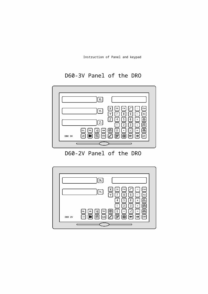
Instruction of Panel and keypad
D60-3V Panel of the DRO
D60-2V Panel of the DRO


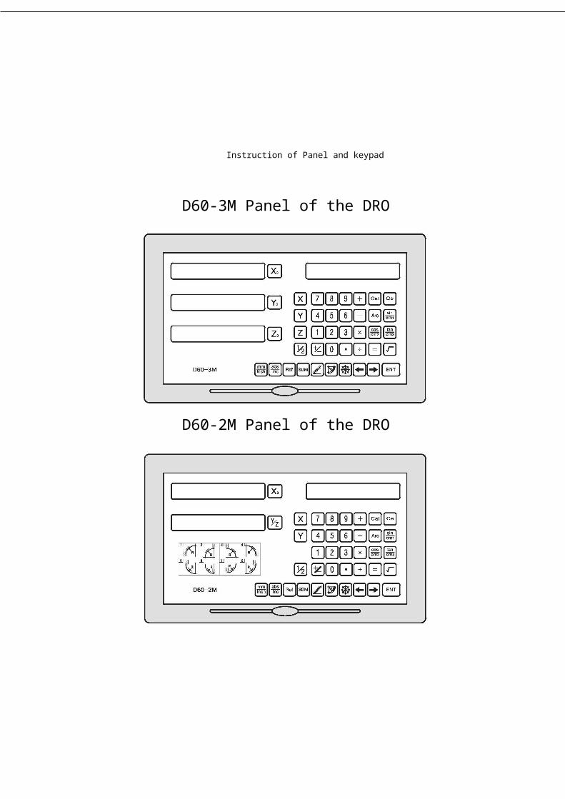
Instruction of Panel and keypad
D60-3M Panel of the DRO
D60-2M Panel of the DRO


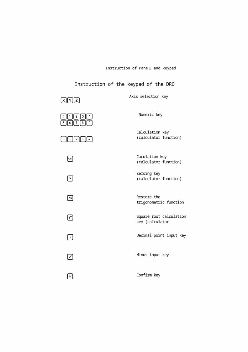
Restore the trigonometric function (calculator function)
Square root calculation key (calculator function)
Decimal point input key
Minus input key
Confirm key
Instruction of Pane丨 and keypad
Instruction of the keypad of the DRO
Axis selection key
Numeric key
Calculation key (calculator function)
Caculation key (calculator function)
Zeroing key (calculator function)
Instruction of Panel and keypad
Delete the input value (calculator function)
1/2 value calculation function key
Arc machining function (PRD) key
Divide holes on Circumference(PCD) function keyY+Z enabling key (L series DROs)
Divide holes on an oblique line (PLD) function key
This key is the sine function key in the calculation function;Bevel machining function key (M series DROs)
This key is the cosine function key in the calculation function; Rectangular box machining key (M series DROs)
The Metric/British units Switching key
Scale key I Sleeping function key
200 Points Auxiliary Zero Position Function key

Instruction of Panel and keypad
Tangent function key of calculation function
Absolute I relative coordinates transformation keySelection key
Taper checking function key
Tool magazine input key
Tool magazine call key
Congruous Output Function in EDM (3V DROs)
Zeroing, reseting
Digital filtering function key(2V DROs) '


Content
Content1_ Introduction about D60-M Series
1.12M DROs for 2 axis milling machines1.23M DROs for 3 axis milling machines
D60-V Series
1.32V DROs for 2 axis lathes1.42V DROs for 2 axis milling machines1.52V DROs for 2 axis grinding machines1.6 3V DROs for 3 axis lathes1.73V DROs for 3 axis milling machines1.83V DROs for EDM
2. System Parameters Setting
2.1 Selection of Linear Encoder or Rotary Encoder2.2 Resolution Setting2.3 Counting Direction Selection2.4 Compensation Type Tetting2.5 Parameter Setting of Rotary Encoder2.6 DRO Type Selection
3. Basic Functions
3.1 Zeroing, Data Recovery3.2 Display in Metric/British units3.3 Input Coordinate3.4 1/2 Function3.5 ABS/INC Way3.6 Full zeroing 200 points SDM3.7 Power Off Memory Function3.8 Sleeping Function3.9 Ref Ruler storage function
3.9.1 Find Zero Point of grating ruler (FIND.REF)
Content
3.9.2 Find the Zero Point (RECALL)3.10 Linear Compensation3.11 Non-linear Compensation
3.12 200 Points Auxiliary Zero Position Function4. Special Function
4.1 PLD Function4.2 PCD Function4.3 Smooth R Function4.4 Simple R Function4.5 Rectangle Chambering Function4.6 Bevel Machining Function4.7 Calculator Function
4.8 Special Functions for Grinding Machines
4.8.1 Digital Filtering Function
4.9 Special Functions for Lathes
4.9.1 200 sets of tools4.9.2 Toper Measuring Function
4.9.3 Radius/diameter Conversion Function4.9.4 Y + Z function (special for 3 axis lathes)
4.10 EDM Function
4.10.1 Introduction and Operation sequences5. Appendix
5.1 Specifications5.2 Mechanical dimensions and Installation Drawing5.3 Troubleshooting

1. Introduction
1. Introduction
1

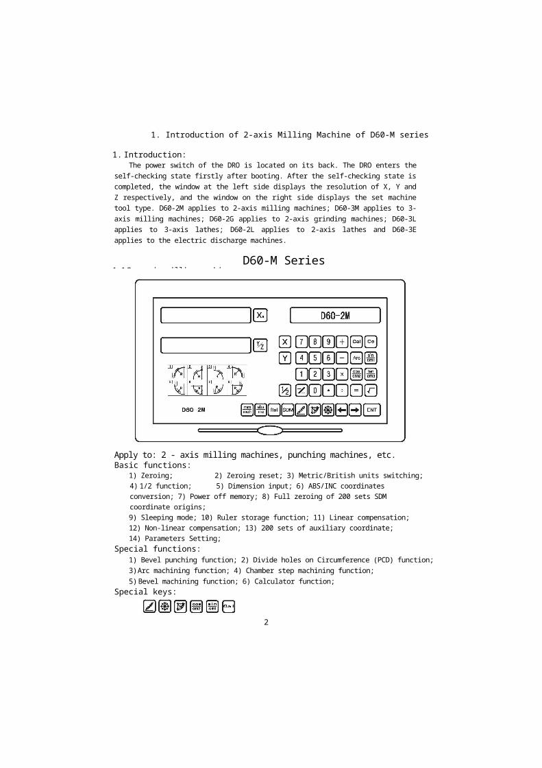
1. Introduction of 2-axis Milling Machine of D60-M series
1. Introduction:The power switch of the DRO is located on its back. The DRO enters the self-checking
state firstly after booting. After the self-checking state is completed, the window at the left side displays the resolution of X, Y and Z respectively, and the window on the right side displays the set machine tool type. D60-2M applies to 2-axis milling machines; D60-3M applies to 3-axis milling machines; D60-2G applies to 2-axis grinding machines; D60-3L applies to 3-axis lathes; D60-2L applies to 2-axis lathes and D60-3E applies to the electric discharge machines.
D60-M Series1.1 2 - axis milling machine
2
Apply to: 2 - axis milling machines, punching machines, etc.Basic functions:
1) Zeroing; 2) Zeroing reset; 3) Metric/British units switching;4) 1/2 function; 5) Dimension input; 6) ABS/INC coordinates conversion; 7) Power off memory; 8) Full zeroing of 200 sets SDM coordinate origins;9) Sleeping mode; 10) Ruler storage function; 11) Linear compensation;12) Non-linear compensation; 13) 200 sets of auxiliary coordinate;14) Parameters Setting;
Special functions:1) Bevel punching function; 2) Divide holes on Circumference (PCD) function;3) Arc machining function; 4) Chamber step machining function;5) Bevel machining function; 6) Calculator function;
Special keys:
1. Introduction of 3-axis Milling Machine of D60-M series
1.2 3 - axis milling machine
3
Apply to: 3 - axis milling machines, punching machines, etc.Basic functions:
1) Zeroing; 2) Zeroing reset; 3) Metric/British units switching;4) 1/2 function; 5) Dimension input; 6) ABS/INC coordinates conversion;
7) Power off memory; 8) Full zeroing of 200 sets SDM coordinate origins;9) Sleeping mode; 10) Ruler storage function; 11) Linear compensation;12) Non-linear compensation; 13) 200 sets of auxiliary coordinate;14) Parameters Setting;
Special functions:1) Bevel punching function; 2) Divide holes on Circumference (PCD) function;
3) Arc machining function; 4) Chamber step machining function;5) Bevel machining function; 6) Calculator function;
Special keys:

1. Introduction of 2-axis lathe of D60-V series
D60-V Series
1.3 2 - axis lathe
4
Apply to: 2 - axis latheBasic functions:
1) Zeroing; 2) Zeroing reset; 3) Metric/British units switching;4) Dimension input; 5) ABS/INC coordinates conversion;6) Power off memory; 7) Full zeroing of 200 sets SDM coordinate origins;
8) Sleeping mode; 9) Ruler storage function; 10) Linear compensation;11) Non-linear compensation; 12) 200 sets of auxiliary coordinate;13) Parameters Setting;Special functions:
1) Magazine including 200 sets of tools; 2) Diameter/ radius conversion;3) Toper measuring; 4) Calculator function;
Special keys:

1. Introduction of 2-axis Milling Machine of D60-V series
1.4 2 - axis milling machine
5
Apply to: 2 - axis milling machines, punching machines, etc.Basic functions:
1) Zeroing; 2) Zeroing reset; 3) Metric/British units switching;4) 1/2 function; 5) Dimension input; 6) ABS/INC coordinates conversion; 7) Power off memory; 8) Full zeroing of 200 sets SDM coordinate origins;9) Sleeping mode; 10) Ruler storage function; 11) Linear compensation;12) Non-linear compensation; 13) 200 sets of auxiliary coordinate;14) Parameters Setting;Special functions:1) Bevel punching function; 2) Divide holes on Circumference (PCD) function;3) Arc machining function; 4) Chamber step machining function;5) Bevel machining function; 6) Calculator function;
Special keys:


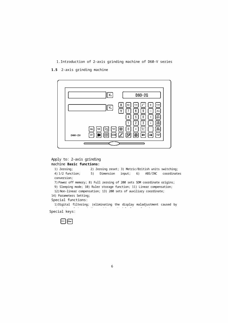
1.Introduction of 2-axis grinding machine of D60-V series
1.5 2-axis grinding machine
Apply to: 2-axis grinding machine Basic functions:
1) Zeroing; 2) Zeroing reset; 3) Metric/British units switching;4) 1/2 function; 5) Dimension input; 6) ABS/INC coordinates conversion;7) Power off memory; 8) Full zeroing of 200 sets SDM coordinate origins;9) Sleeping mode; 10) Ruler storage function; 11) Linear compensation;12) Non-linear compensation; 13) 200 sets of auxiliary coordinate;
14) Parameters Setting;Special functions:
1) Digital filtering; (eliminating the display maladjustment caused by the shake of the grinding machine); 2) Calculator function;
6
Special keys:


1. Introduction of 3-axis lathe of D60-V series
Apply to: 3-axis lathe Basic functions:1) Zeroing; 2) Zeroing reset; 3) Metric/British units switching;
4) Dimension input; 5) ABS/INC coordinates conversion;6) Power off memory; 7) Full zeroing of 200 sets SDM coordinate origins;8) Sleeping mode; 9) Ruler storage function; 10) Linear compensation;
11) Non-linear compensation; 12) 200 sets of auxiliary coordinate;13) Parameters Setting;Special functions:
1) Magazine including 200 sets of tools; 2) Diameter/ radius conversion;3) Toper measuring; 4) Calculator function;5) Y+Z function;
1.6 3-axis lathe
7
Special keys:

1. Introduction of 3-axis Milling Machine of D60-V series
1.7 3 - axis milling machine
8
Apply to: 3 - axis milling machines, punching machines, etc.Basic functions:
1) Zeroing; 2) Zeroing reset; 3) Metric/British units switching;4) 1/2 function; 5) Dimension input; 6) ABS/INC coordinates conversion;7) Power off memory; 8) Full zeroing of 200 sets SDM coordinate origins;9) Sleeping mode; 10) Ruler storage function; 11) Linear compensation;12) Non-linear compensation; 13) 200 sets of auxiliary coordinate;14) Parameters Setting;
Special functions:1) Bevel punching function; 2) Divide holes on Circumference (PCD) function;3) Arc machining function; 4) Chamber step machining function;5) Bevel machining function; 6) Calculator function;
Special keys:

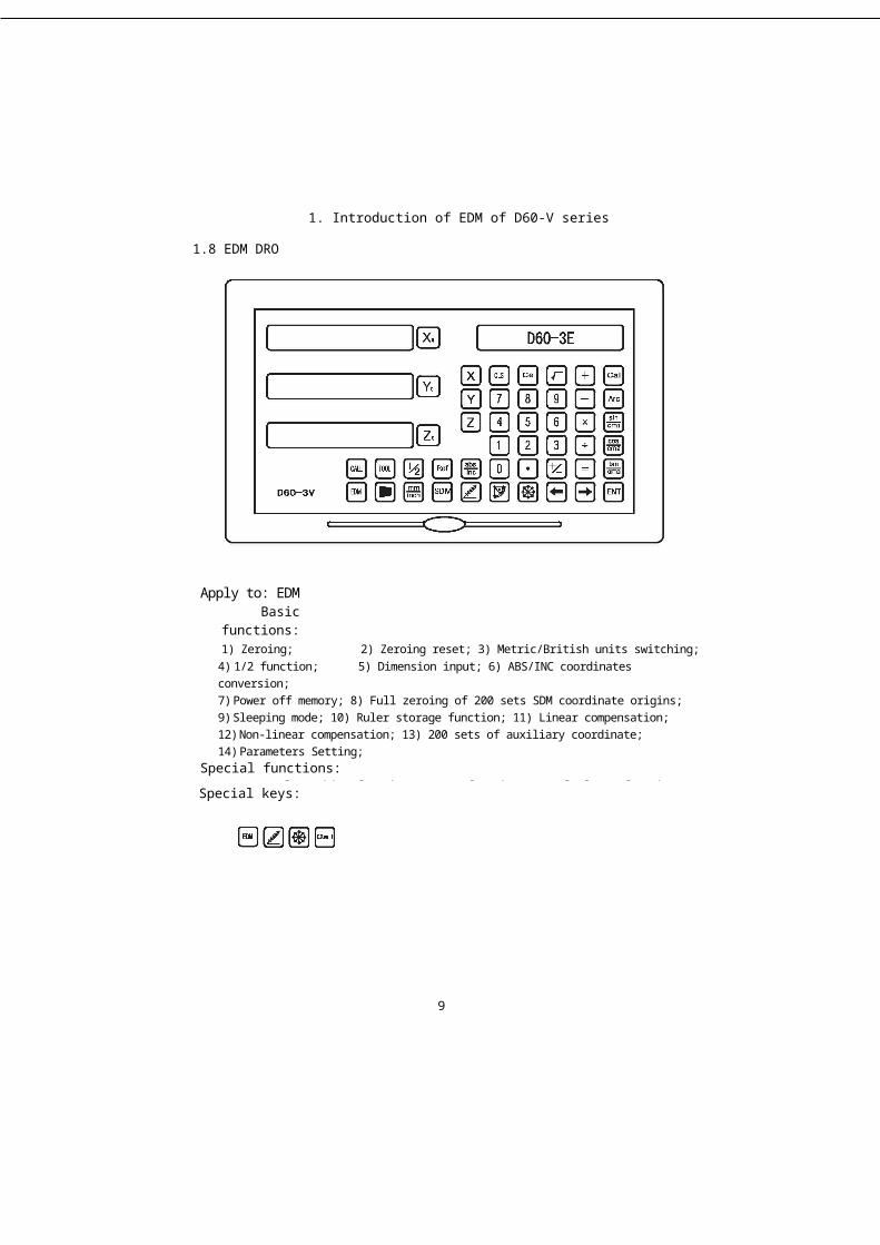
1. Introduction of EDM of D60-V series
1.8 EDM DRO
Apply to: EDM Basic functions:
1) Zeroing; 2) Zeroing reset; 3) Metric/British units switching;4) 1/2 function; 5) Dimension input; 6) ABS/INC coordinates conversion;7) Power off memory; 8) Full zeroing of 200 sets SDM coordinate origins;9) Sleeping mode; 10) Ruler storage function; 11) Linear compensation;12) Non-linear compensation; 13) 200 sets of auxiliary coordinate;14) Parameters Setting;
Special functions:1) Bevel punching function; 2) PCD function; 3) Calculator function;
4) Electric discharge machine (EDM) function;
9
Special keys:


2. System parameter setting
2. System parameter setting
2. System parameter setting
2.2: Resolution setting (Set resolution for the corresponding encoder)For linear encoder, set the resolution as follows:Fixed resolution selection: 0.1 um, 0.2um, 0.5um, 1um, 2um, 2.5um, 5um and 10um. Presskey to alter the resolution of X axis. Press key to alter the resolution of Y axis.
For rotary encoder, set the resolution as follows: (set the resolution of the rotary encoder in the following way). The rotary encoder can display in two ways. When entering the resolution in the way of positive number, the rotary encoder displays in degree (D). When entering the resolution in the way of negative number, the rotary encoder displays in degrees/minutes/seconds (DMS).
11
2:System parameter settingThe power switch of the DRO is located on its back. The DRO enters the self-checking
state firstly after booting, which includes checking whether the LED display is normal and whether the setting of system resolution and model is appropriate. The self-checking state will sustain until DRO enters normal display state.
Press thekey once during the self-checking process, then the DRO will enter system parameter setting state. (Note that pressing just once is OK. If pressing twice, the system will skip the self-checking process and enter normal display state.
In the system parameter setting, we can set parameters as follows: 1) encoder type selection (linear encoder or rotary encoder); 2) resolution setting (Fixed resolution:0. 1um, 0.2um, 0.5um, 1um, 2um, 2.5um, 5um andlOum.); 3) Counting direction setting (0 indicates positive direction, 1 indicates negative direction); 4) compensation type setting (linear or nonlinear compensation); 5) parameter setting of rotary encoder; 6) DRO type selection;
2.1: Encoder type selection (LINER stands for a linear displacement transducer matching the axis. Rotary stands for a rotary encoder matching the axis);
Press key to alter the encoder type of X axis;Press key to alter the encoder type of Y axis;Press key to alter the encoder type of Z axis;Press key to enter step 2 and press key to save and exit parameter setting.


2. System parameter setting
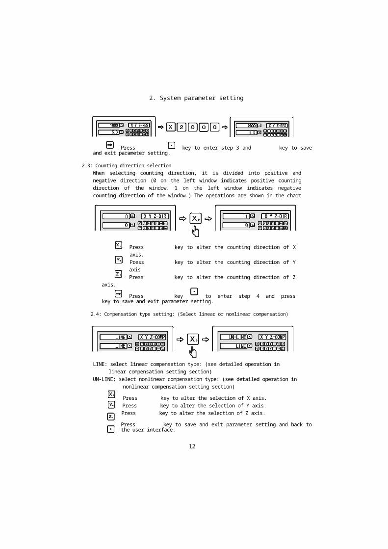
Press key to enter step 3 and key to save and exit parameter setting.
2.3: Counting direction selectionWhen selecting counting direction, it is divided into positive and negative direction (0 on the left window indicates positive counting direction of the window. 1 on the left window indicates negative counting direction of the window.) The operations are shown in the chart below.
Press key to alter the counting direction of X axis.Press key to alter the counting direction of Y axisPress key to alter the counting direction of Z axis.
Press key to enter step 4 and press key to save and exit parameter setting.
2.4: Compensation type setting: (Select linear or nonlinear compensation)When entering the compensation type setting, LINE on the left window indicates linear compensation for the window. UN-LINE on the left window indicates nonlinear compensation for the window. The operations are shown in the chart below.
12
LINE: select linear compensation type: (see detailed operation in linear compensation setting section)
UN-LINE: select nonlinear compensation type: (see detailed operation in nonlinear compensation setting section)
Press key to alter the selection of X axis.Press key to alter the selection of Y axis.Press key to alter the selection of Z axis.
Press key to save and exit parameter setting and back to the user interface.


2.System parameter setting
2.5: Parameter setting of rotary encoderEnter system parameter setting and select rotary encoder.Information
screen displays L/R TYPE and X axis displays Rotary, then press key to enter the resolution setting of the rotary encoder when information screen displays XYZ-RES. The resolution varies among different types of encoder, so you have to enter resolution for the corresponding rotary encoder type. When entering resolution, negative value results in degrees/minutes/seconds (DMS) counting mode and positive value results in degree (D) counting mode. This DRO supports a maximum resolution of 99999.
Example: Set the resolution of rotary encoder as 1000P/R
Input the resolution of X axis as +1000 and -1000 to Y axis
X axis counts in degree (D) mode andY axis counts in degrees, minutes andseconds (DMS) mode
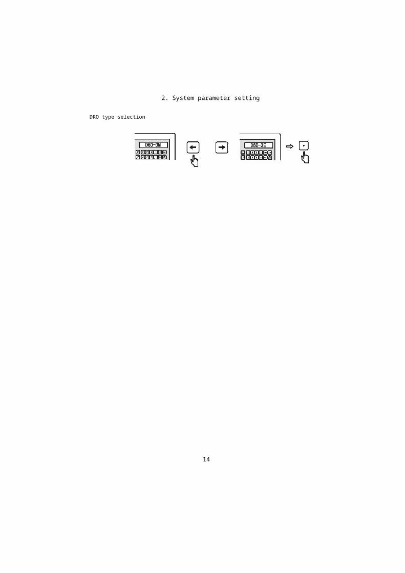
2.6: DRO type selection
D60-3V multifunction DRO applies to 3-axis milling machines (D60-3M), 3-axis lathes (D60-3L) and EDMs (D60-3E). D60-2V multifunction DRO applies to 2-axis milling machines (D60-2M) and 2-axis lathes (D60-2L) and 2-axis grinding machines (D60-2G).
D60-3V and D60-2V multifunction DROs are easy to set and apply to milling machine, lathe, grinding machine and EDM etc. Afterbooting, press key once to enter the DRO type selection, then press and keys to select the type until the required type appears on the right and press key to save and exit to the main menu.
13
After inputting the resolution p r e s s k e y to exit system parameter setting and back to the main menu.

DRO type selection
2. System parameter setting
14

3. Basic functions
2. Basic functions
15
3. Basic functions
3.Basic functions3.1Zeroing, data recovery
Function: Operator could zero the displayed coordinate at any position.Example 1: Zero the displayed value of X axis at the current position.
Press key to recover the displayed data of Y axis;Press key to recover the displayed data of Z axis;
3.2 Display in Metric/British unitsFunction: Display the location size in Metric (mm) or British (inch) units.Example 1: Switch the British (inch) units currently displayed to the Metric (mm) units.
Example 2: Switch the Metric (mm) units currently displayed to the British (inch) units.
16
Press key to zero the displayed data of Y axis;Press key to zero the displayed data of Z axis;
Data recoveryFunction: Recover the data which has been zeroed by mistake at any position. Example 2: Realize the data recovery of X axis.


3. Basic functions
3.3 Input coordinatesFunction: Enable the operator to set the current position at any value. Example 1: Set the position of the current X axis as 16.800 .
Example 2: Set the position of the current Y axis as -6.800
Example 3: Set the position of the current Z axis as 8.250
3.4 Automatic Centre FindFunction: DRO provides automatic centre find function which divides the current
displayed position by 2 and sets the zero point at the centre of work piece.
Example 1: Set the zero point of X axis at the centre of work piece
Step 1: Align the optical edge finder on one side of X axis of work piece then clear to zero.
Step 2: Align the optical edge finder on the other side of X axis of work piece.
17


3. Basic functions
Step 3: Divide the current display of X axis by 2 according to centre find function.
The X-axis centre of the work piece is 0.000. Move the grating ruler to 0.000,which is the centre of the work piece.
Example 2: Press key to convert the current INC coordinate to ABS coordinate
18
3.5 ABS/INC CoordinatesFunction: DRO provides two sets of standard coordinate display value, namely ABS
(absolute) and INC (relative) coordinates. The operator could store the reference zero point of work piece at ABS coordinate, and convert ABS coordinate to INC coordinate for machining. Zeroing at any position at INC coordinate won , t affect the length value relative to the reference zero point of work piece at ABS coordinate, which shall be stored during the whole machining process and could be checked whenever necessary.
Example 1: Press key to convert the current ABS coordinate to INC coordinate

3. Basic functions
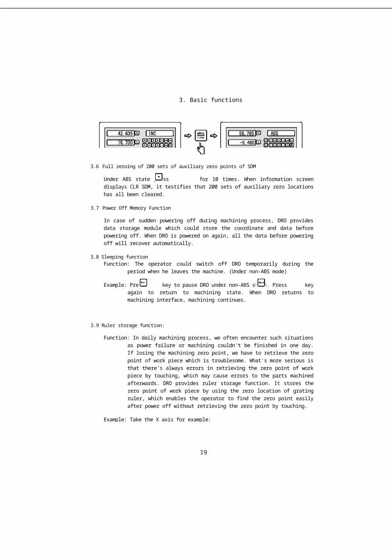
3.6 Full zeroing of 200 sets of auxiliary zero points of SDM
Under ABS state press for 10 times. When information screen displays CLR SDM, it testifies that 200 sets of auxiliary zero locations has all been cleared.
3.7 Power Off Memory Function
In case of sudden powering off during machining process, DRO provides data storage module which could store the coordinate and data before powering off. When DRO is powered on again, all the data before powering off will recover automatically.
3.8 Sleeping functionFunction: The operator could switch off DRO temporarily during the period when he
leaves the machine. (Under non-ABS mode)
Example: Press key to pause DRO under non-ABS state. Press key again to return to machining state. When DRO returns to machining interface, machining continues.
3.9 Ruler storage function:
Function: In daily machining process, we often encounter such situations as power failure or machining couldn't be finished in one day. If losing the machining zero point, we have to retrieve the zero point of work piece which is troublesome. What's more serious is that there's always errors in retrieving the zero point of work piece by touching, which may cause errors to the parts machined afterwards. DRO provides ruler storage function. It stores the zero point of work piece by using the zero location of grating ruler, which enables the operator to find the zero point easily after power off without retrieving the zero point by touching.
Example: Take the X axis for example:
19

3. Basic functions
Note: The ruler storage function in our DRO is the most advanced and easiest to use in the DRO market. Each time the operator uses functions which may affect the zero point such as Zeroing, finding centre and inputting coordinate under ABS coordinate, DRO will store the distance between zero point of work piece and ruler centre. So the operator only need operate under the ABS coordinate to set the origin before either switching on the DRO or machining (the work piece hasn't been clamped onto the table). Through which the DRO will record the zero location of the ruler. Then DRO will deal with other storage processes without bothering the operator.
3.9.1Ruler storage function (set the origin):Function: When machining a complex work piece, its zero point couldn't lose under the
cases of power off or failing to finish machining in one day. In this case we could set the origin under the ABS coordinate state of DRO to store the origin of the work piece into DRO. DRO will memorize the distance between the zero point of new work piece and ruler centre during all the operations of resetting the work pieced zero point under ABS coordinate such as Zeroing, finding centre and inputting coordinate so as to retrieve the work piece,s zero point after power off or closing ruler.
20
Step 1: Enter REF function and select REF to set the origin.
3. Basic functions
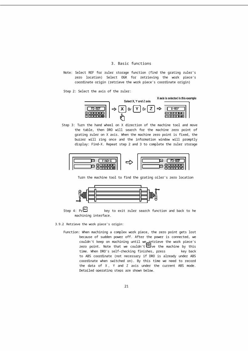
Note: Select REF for ruler storage function (find the grating ruler's zero location) Select OGR for retrieving the work piece's coordinate origin (retrieve the work piece's coordinate origin)
Step 2: Select the axis of the ruler:
Step 3: Turn the hand wheel on X direction of the machine tool and move the table, then DRO will search for the machine zero point of grating ruler on X axis. When the machine zero point is fixed, the buzzer will ring once and the information window will promptly display: Find-X. Repeat step 2 and 3 to complete the ruler storage function of Y and Z axis.
Turn the machine tool to find the grating oiler's zero location
Step 4: Press key to exit ruler search function and back to he machining interface.
3.9.2Retrieve the work piece’s origin:
Function: When machining a complex work piece, the zero point gets lost because of sudden power off. After the power is connected, we couldn't keep on machining until we retrieve the work piece's zero point. Note that we couldn't move the machine by this time. When DRO's self-checking finishes, press key back to ABS coordinate (not necessary if DRO is already under ABS coordinate when switched on). By this time we need to record the data of X,Y and Z axis under the current ABS mode. Detailed operating steps are shown below.
21
3. Basic functions
Step 1: Record the data of X,Y and Z axis under ABS mode when DRO completes self-checking:
Example: If DRO completes switch-on self-checking under ABS mode X axis is 12.500 Yaxis is 18.230 Z axis is 5.800 .
Note: DRO couldn't deal with the data of X, Y and Z axis automatically, so they need to be recorded to find the zero point.
Step 2: Enter REF function and select the function of retrieving the work piece'soriain:
Note: Select REF for ruler storage function (find the grating ruler's zero location) Select OGR for retrieving the work piece’s coordinate origin (retrieve the work piece’s coordinate origin)
Step 3: Turn the hand wheel on X direction of the machine and move the table, then DRO will find for the machine zero point of grating ruler on X axis. When the zero point is found, the buzzer will ring once and the information window will promptly display: Find-X. Repeat step 2 and 3 to complete retrieving the work piece,s origin of Y and Z axis.
22
3. Basic functions
Turn the machine to find the grating ruler's zero location
Step 4: After searching the work piece,s origins on X,Y and Z axis, turn the machine under ABS coordinate state. When the coordinates of X,Y and Z axis are the ABS coordinates recorded at power-on self-checking, this point is the one when machining stopped at last power off and we could go on machining the unfinished work piece.
Example: Turn the machine to the coordinates recorded manually at power-on self-checking under ABS mode.
Turn the machine to retrieve the working point when machining stopped at last power off.
Press key to exit the ruler tracking number function.
Note: Retrieve the work piece’s origin. The data couldn’t be recovered until the origin is set before machining.
3.10 Linear compensation
Function: Linear error compensation function is used to correct the system errors of the grating ruler measurement system linearly.
23

3. Basic functions
Note: the calculation formula of correction coefficient is:Correction coefficientS = (L-L1) I ( L 1 1000) mm/m L: Stands for the actual measured length (mm)L1: Stands for the displayed value (mm) on the DRO S: Stands for correction coefficient (mm/m) (+ indicating lengthening and - indicating shortening)
Compensation range: -1.9 mm/m to + 1.9 mm/m
Example: The actual length of the machine's X axis table is 1000.000mm and the displayed value on the DRO is 999.880mm. The correction coefficient is calculated as follows:
S= (1000.000-999.880) I (1000.000/1000.000) =0.120
Set the linear compensation coefficient according to the following operation (Note: Set the compensation method as linear compensation in the system parameter setting section firstly. The detailed operations are described in system parameter setting section.)
Step 1: p r e s s k e y a n d t h e n k e y and the DRO will enter linear compensation setting.
Step 2: Input the correction coefficient, then press key and the linear compensation function will be prompted automatically.
Note: The linear compensation operation of Y axis or Z axis resembles that of X axis.
24

3. Basic functions
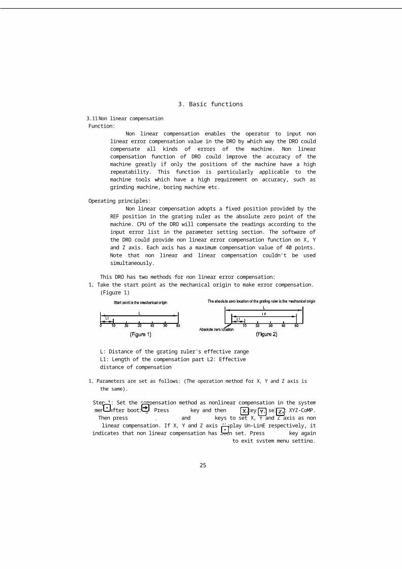
L: Distance of the grating ruler's effective range L1: Length of the compensation part L2: Effective distance of compensation
1、Parameters are set as follows: (The operation method for X,Y and Z axis is the same).
Step 1: Set the compensation method as nonlinear compensation in the system menu after booting. Press key and then key to select XYZ-CoMP. Then press , and
keys to set X,Y and Z axis as non linear compensation. If X,Y and Z axis display Un-LinE respectively, it indicates that non linear compensation has been set. Press key again to
exit system menu setting.
25
3.11 Non linear compensationFunction:
Non linear compensation enables the operator to input non linear error compensation value in the DRO by which way the DRO could compensate all kinds of errors of the machine. Non linear compensation function of DRO could improve the accuracy of the machine greatly if only the positions of the machine have a high repeatability. This function is particularly applicable to the machine tools which have a high requirement on accuracy, such as grinding machine, boring machine etc.
Operating principles:Non linear compensation adopts a fixed position provided by the REF
position in the grating ruler as the absolute zero point of the machine. CPU of the DRO will compensate the readings according to the input error list in the parameter setting section. The software of the DRO could provide non linear error compensation function on X, Y and Z axis. Each axis has a maximum compensation value of 40 points. Note that non linear and linear compensation couldn't be used simultaneously.
This DRO has two methods for non linear error compensation:1、Take the start point as the mechanical origin to make error compensation. (Figure 1)2、 Take the first absolute zero point of the grating ruler as the mechanical origin to make
error compensation. (Figure 2)
3. Basic functions
Step 2: Move the grating ruler to the minimum end of coordinate data for Zeroing. DRO enters the ABS absolute coordinate display method.
Set according to Figure 1:
Set according to Figure 2:
Step 6: Select the start point (non linear compensation takes the zero location as the start point. There are two kinds of zero location: a. the left zero, b. the mechanical zero location under ABS coordinates. Select by pressing and keys)
26
Step 3: Press key and then key to enter the non linear compensation function of X axis and input the relative parameters.
Step 4: Input the compensation part number
Note: The compensation part number of any axis should be inputted on X axis.
Step 5: Input the length of each compensation part
3. Basic functions
Method A: Zeroing at left Method B: zero location under ABS coordinates
Method A (zeroing at left), clear the start point at the left and confirm by pressing key. Method B (ABS zero location), the operation is similar to finding the zero locationunder REF. It enters the compensation interface automatically after finding the zero location.
Zero location is a counting point and the most important reference point of non linear compensation. After entering the compensation interface, X axis displays the actual data of the grating ruler and Y axis displays the compensation value of the compensation axis.
Step 7: Input the adjusted values segmentally and press key to enter the next point.
X axis displays the actual moving value of the grating ruler and Y axis displays the corrected value. When inputting the corrected value, we should measure from the start point to the displayed corrected value position of Y axis firstly and then move the X axis grating ruler to the measured standard value position.
Press key to set the next point.Note: In this function the compensation range couldn't exceed Imm/m, or the compensation is set as 0.
2、Method of cancelling non linear compensation value:
Non linear compensation value could only be used to the DRO, grating ruler and machine when they are set together. When a grating ruler or DRO whose compensation value has been set on a certain machine is moved to another machine, this non linear compensation value is incorrect. In this case we should cancel or reset the non linear compensation value.
27
3. Basic functions
The method of cancelling is:According to the non linear compensation set method indicated above, input the
compensation part as 0 when prompted to initialize all the compensation parameters. At present all the compensation parameters set before will be invalid and the current compensation value is zero.
3、Method of retrieving the mechanical originWhen it was power off during grating ruler movement or grating ruler moved
without power on, we have to find the mechanical origin again before booting. Because when the machine is moved under power off, the origin of the machine coordinate couldn't match the value on the DRO. If we don't retrieve the mechanical origin, such dislocation will be brought into the subsequent user coordinate system, as the non linear compensation value is set based on wrong mechanical coordinate when calculating the user coordinate, which brings errors to display coordinate.
Set the mechanical origin as follows:Enter non linear compensation after booting. When inputting compensation part
number and compensation length, make no change and press key directly to skip. Then we come to select the compensation start point, select ABS-ZERO (ABS zero location) and press key to find the zero location. At this time the information screen displays RESET-X, slide the X axis grating ruler to find the zero location until DRO gives out a sound. System has entered the compensation interface automatically then press key to exit non linear compensation.
Note:The work origin could only be retrieved when the start point of non linear
compensation is set at the ABS zero location. If set the leftmost as the ABS zero location, the work origin couldn't be retrieved. At this time we have to reset the non linear compensation. The following method is recommended for setting non linear compensation: set the compensation start point as ABS zero location. The user searches the mechanical origin after each booting to guarantee the consistency of the mechanical origins.
3.12 200 sets of auxiliary zero location:
Function:Typical grating DRO only provides two groups of coordinates, namely ABS/INC. But
in most of the daily machining occasions, operators always find it not enough, especially in die machining or small batch machining. The DRO provides 200 sets of auxiliary zero location (SDM) function to compensate for the shortage of the ABS/INC function. But SDM is not just a simple additional INC coordinate, it has the following difference compared to ABS/INC.
28
3. Basic functions
1. INC zero location is completely independent. Regardless of any change in ABS zero location, INC zero location will never change. But the zero location of SDM is relative to ABS, which means when ABS zero location changes, all the SDM zero locations shall change correspondingly.
2. The distance of SDM relative to ABS coordinate could be entered by keys directly, which is both fast and precise.
Applications of SDM in sub zero point:Operators could set each sub zero location on the work piece in the SDM
auxiliary zero location coordinates.
Press key or key to convert to SDM auxiliary zero location directly without returning to ABS coordinate.
Applications of SDM in small batch machiningSDM function could store batch of working point positions in SDM zero location.
Operators could enter all the working points to the DRO at once. Alternatively, operators could also input the working points into SDM of DRO when machining the first work piece. Afterwards they only need to adjust the reference zero location of the subsequent work pieces in ABS coordinate. As the SDM zero locations correspond to these of ABS, all the working point shall recur by SDM zero locations.
29
3. Basic functions
Inputthe required coordinate value under SDM state according to SDM or press and keys to turn to each SDM auxiliary zero location. Move the machine until each SDM coordinate displays 0,which is the position of each working point.
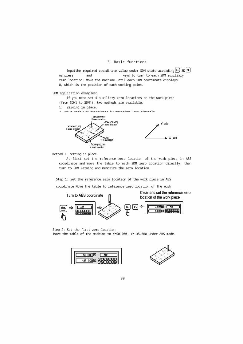
SDM application examples:If you need set 4 auxiliary zero locations on the work piece (from SDM1 to
SDM4), two methods are available:1. Zeroing in place.2. Input each SDM coordinate by pressing keys directly.
Step 2: Set the first zero locationMove the table of the machine to X=50.000, Y=-35.000 under ABS mode.
Method I: Zeroing in placeAt first set the reference zero location of the work piece in ABS coordinate and
move the table to each SDM zero location directly, then turn to SDM Zeroing and memorize the zero location.
Step 1: Set the reference zero location of the work piece in ABS coordinate
Move the table to reference zero location of the work piece
30
3. Basic functions
Step 3: Set the second zero locationEnter the ABS coordinate system according to the following operation. Move the
table of the machine to fix the tool at the position of X=50.000, Y=50.000.
Step 4: Set the third zero locationEnter the ABS coordinate system according to the following operation. Move the
table of the machine to fix the tool at the position of X=-50.000, Y=50.000 .
31
Enter SMDO according to the figure below
zeroing as following methods
Enter the SDM1 coordinate system according to the following operation zeroing as following methods
Enter the SDM1 coordinate system according to the following operation zeroing as following methods

3. Basic functions
Step 5: Set the forth zero locationEnter the ABS coordinate system according to the following operation. Move the
table of the machine to fix the tool at the position of X=-50.000, Y=-35.000 .
Press and keys to check whether the SDM coordinate inputted is correct. Checking operation as follows (check the coordinate of SDM3 origin under ABS, SDMO, SDM1, SDM2 and SDM3 coordinate systems.)
32
Enter the SDM1 coordinate system according to the following operation zeroing as following methods
The present values of SDM3 origin correspond to ABS absolute coordinate system
Enter the ABS coordinate system according to the following operation
The present values of SDM3 origin correspond to SDMO coordinate systemEnter the SDMO coordinate system
according to the following operation
The present values of SDM3 origin correspond to SDM 1 coordinate systemEnter the SDM1 coordinate system
according to the following operation
3. Basic functions
Zeroing in place is simple and clear, but lots of SDM zero locations have to be built up, which is inefficient, so method 2 is recommended.
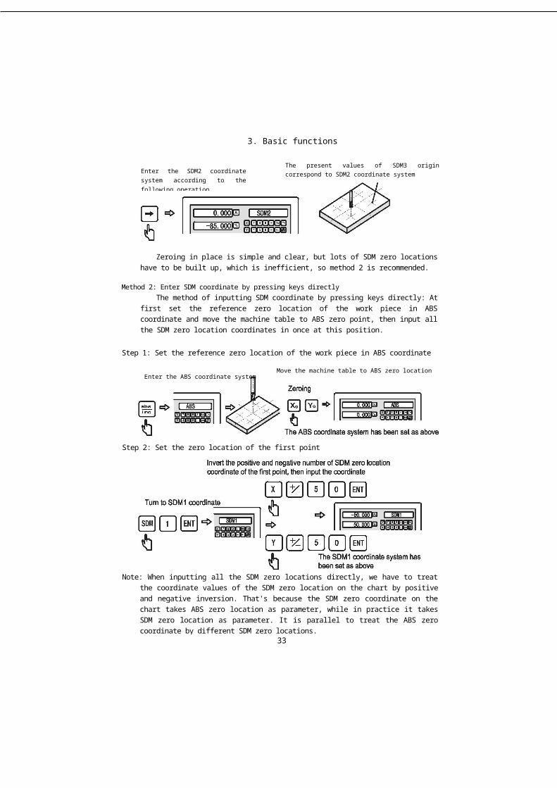
Method 2: Enter SDM coordinate by pressing keys directlyThe method of inputting SDM coordinate by pressing keys directly: At first set the
reference zero location of the work piece in ABS coordinate and move the machine table to ABS zero point, then input all the SDM zero location coordinates in once at this position.
Step 1: Set the reference zero location of the work piece in ABS coordinate
33
Enter the SDM2 coordinate system according to the following operation
The present values of SDM3 origin correspond to SDM2 coordinate system
Note: When inputting all the SDM zero locations directly, we have to treat the coordinate values of the SDM zero location on the chart by positive and negative inversion. That's because the SDM zero coordinate on the chart takes ABS zero location as parameter, while in practice it takes SDM zero location as parameter. It is parallel to treat the ABS zero coordinate by different SDM zero locations.
Move the machine table to ABS zero location
Step 2: Set the zero location of the first point
Enter the ABS coordinate system

3. Basic functions
Step 3: Set the zero location of the second point
Invert the positive and negative number of SDM zero location coordinate of the second point, then input the coordinate
Step 4: Set the zero location of the third point
Invert the positive and negative number of SDM zero location coordinate of the third point, then input the coordinate
Step 5: Set the zero location of the fourth point
34
Invert the positive and negative number of SDM zero location coordinate of the forth point, then input the coordinate


3. Basic functions
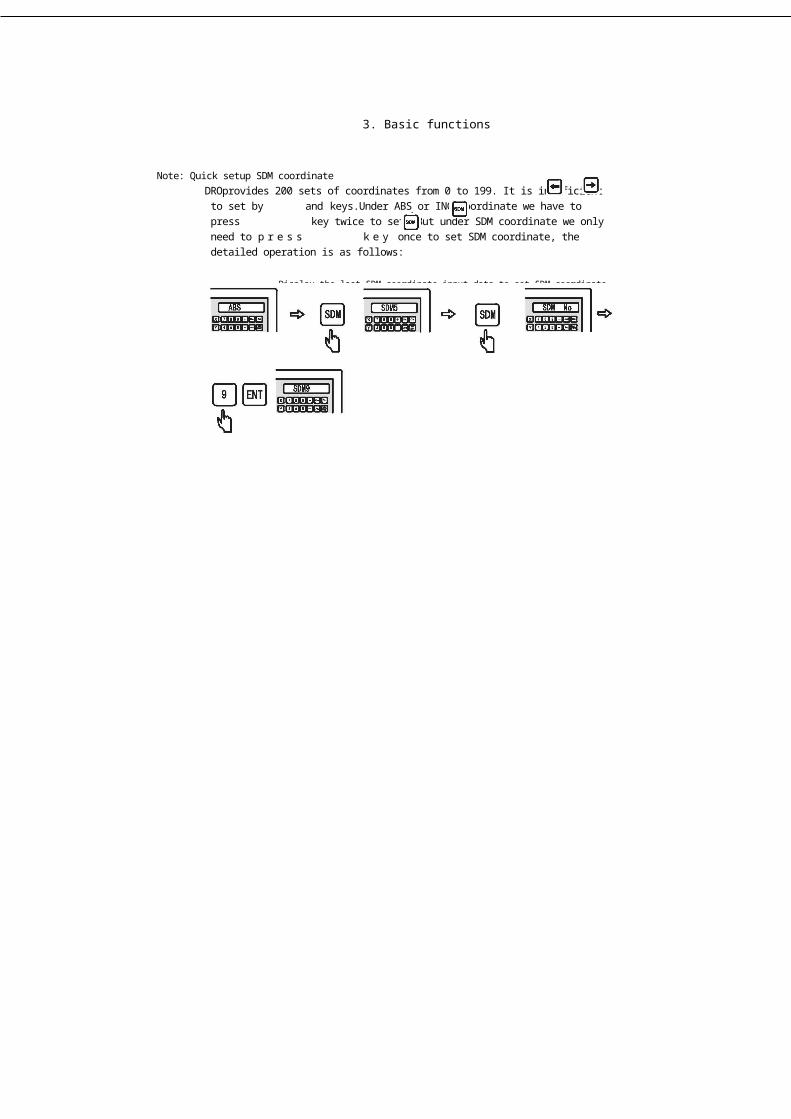
Note: Quick setup SDM coordinateDROprovides 200 sets of coordinates from 0 to 199. It is inefficient to set by and keys.Under ABS or INC coordinate we have to press key twice to set. But under SDM coordinate we only need to p r e s s k e y once to set SDM coordinate, the detailed operation is as follows:
Display the last SDM coordinate input data to set SDM coordinate
35

4. Special Function
4 Special Function
36
4.1 PLD Function
PLD Function
37

4.1 PLD Function
4.2 PLD Function(Applicable to the machine tools: 2M,3M milling machines and Electric Discharge Machines)
We have two ways to realize the PLD function.
Way 1: Length way (L-LEN, the distance from the starting hole center to the ending hole center)
Way 2: Step way (L-STEP, the distance between two adjacent holes)
PLD input parameters:L-LEN:
LENGTH - - oblique line overall length (the distance from the starting hole to the ending hole, as shown in figure B)
ANGLE ___ oblique line angle (as shown in figure A)No HOLE __ hole number (as shown in figure B)
L-STEP:STEP_______ pitch-row length (the distance between two adjacent hole
centers, as shown in figure B)ANGLE - - oblique line angle (as shown in figure A)No HOLE - hole number (as shown in figure B)
Example: as shown in the right figure
Figure A:The angle refers to the positiondirection of the oblique line onthe coordinate plane. Theanti-clockwise direction is thepositive direction, and theclockwise direction is thenegative direction.
38

4.1 PLD Function
Example 1: L-LEN
Step 1: Firstly, move the tool to the position of the starting hole. (L-LEN)Press the key to enter the function of punching on an oblique line.
Step 2: Select the machiningplanePress the and keys to select the “machining plane” and press the key for
confirmation (This setting is only available for 3 M and EDM DRO. Because 2M DRO only contains XY plane, it can jump into the next step directly without selection).
Step 3: Machining way selectionPress the and keys to select “the machining way” and press t h e
k e y for confirmation. Here, we select the L-LEN.
39
Figure B:
oblique line: 60mm oblique line angle: 30mm pitch-row:
20mmholes: 4
(Figure B)
Select the plane
Select the plane
Length way
Step way


4.1 PLD Function
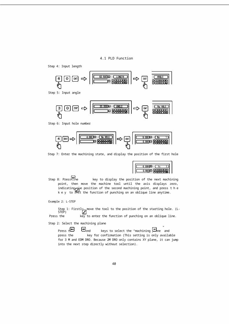
Step 4: Input length
Step 5: Input angle
Step 6: Input hole number
Step 7: Enter the machining state, and display the position of the first hole
Step 8: Press the key to display the position of the next machining point, then move the machine tool until the axis displays zero, indicating the position of the second machining point, and press t h e k e y to exit the function of punching on an oblique line anytime.
Example 2: L-STEP
Step 1: Firstly, move the tool to the position of the starting hole. (L-STEP)Press the key to enter the function of punching on an oblique line.
Step 2: Select the machining plane
Press the and keys to select the “machining plane” and press the key for confirmation (This setting is only available for 3 M and EDM DRO. Because 2M DRO only contains XY plane, it can jump into the next step directly without selection).
40


4.1 PLD Function
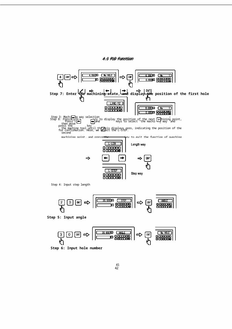
Step 3: Machining way selectionPress the and keys to select “the machining way” and press the key
for confirmation. Here, we select the L-STEP.
Step 6: Input hole number
Step 5: Input angle
Step 4: Input step length
41
4.1 PLD Function
Step 7: Enter the machining state, and display the position of the first hole
Step 8: Press the key to display the position of the next machining point, then movethe machine tool until the axis displays zero, indicating the position of the secondmachining point, and press the key to exit the function of punching on anoblique line anytime.
42


4.2 PCD Function
PCD Function
43

4.2 PCD Function
4.2: PCD Function(Applicable to machine tools: 2M and 3M milling machines and EDM)
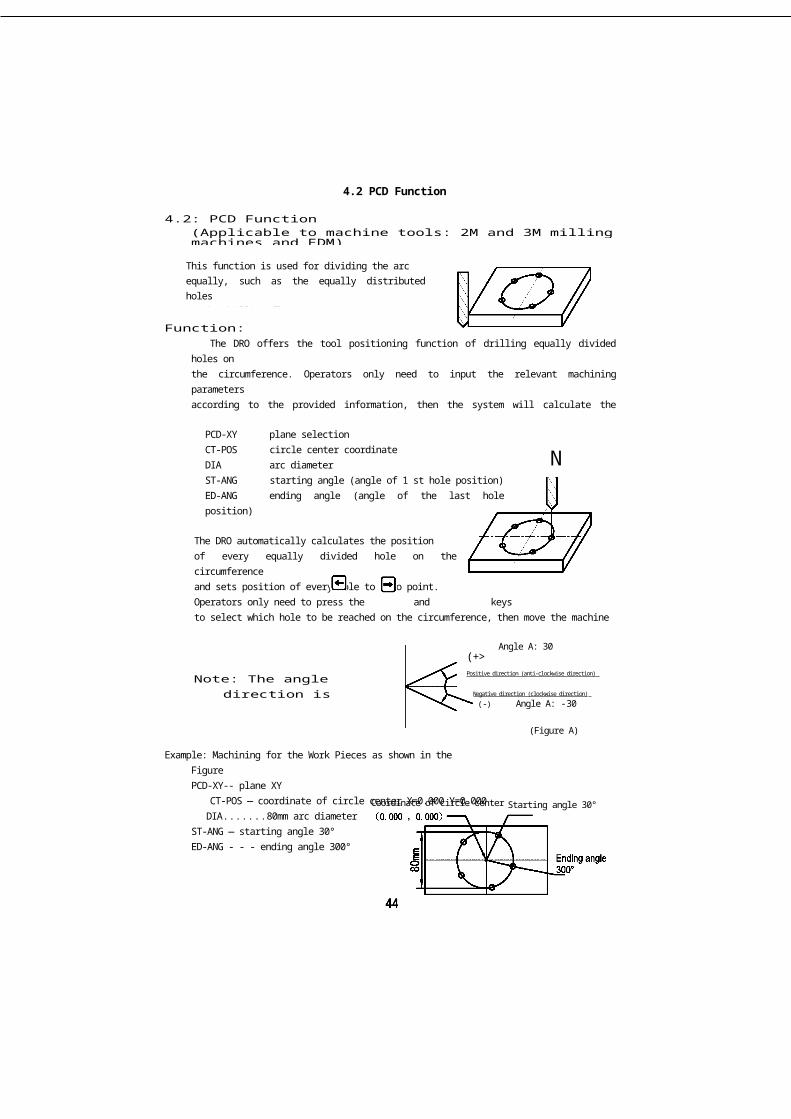
This function is used for dividing the arcequally, such as the equally distributed holeson the drilling flange.
Function:The DRO offers the tool positioning function of drilling equally divided holes on
the circumference. Operators only need to input the relevant machining parametersaccording to the provided information, then the system will calculate the positioncoordinates of holes immediately and set the hole position to zero point (0.000,0.000) temporarily. Operators only need to input the following six parameters.
PCD-XY plane selectionCT-POS circle center coordinateDIA arc diameterST-ANG starting angle (angle of 1 st hole position)ED-ANG ending angle (angle of the last hole position)No HOLE hole number
N
The DRO automatically calculates the positionof every equally divided hole on the circumferenceand sets position of every hole to zero point.Operators only need to press the and keysto select which hole to be reached on the circumference, then move the machinetool until the DRO displays (0.000), i.e. the hole position is reached.
Note: The angle direction is shownin the right figure.
Angle A: 30(+>Positive direction (anti-clockwise direction)
Negative direction (clockwise direction)
(-) Angle A: -30
(Figure A)
Example: Machining for the Work Pieces as shown in the FigurePCD-XY-- plane XY
CT-POS — coordinate of circle center X=0.000 Y=0.000DIA.............80mm arc diameter
ST-ANG — starting angle 30°ED-ANG - - - ending angle 300°No HOLE - - 5 holes
Coordinate of circle center Starting angle 30°

4.2 PCD Function
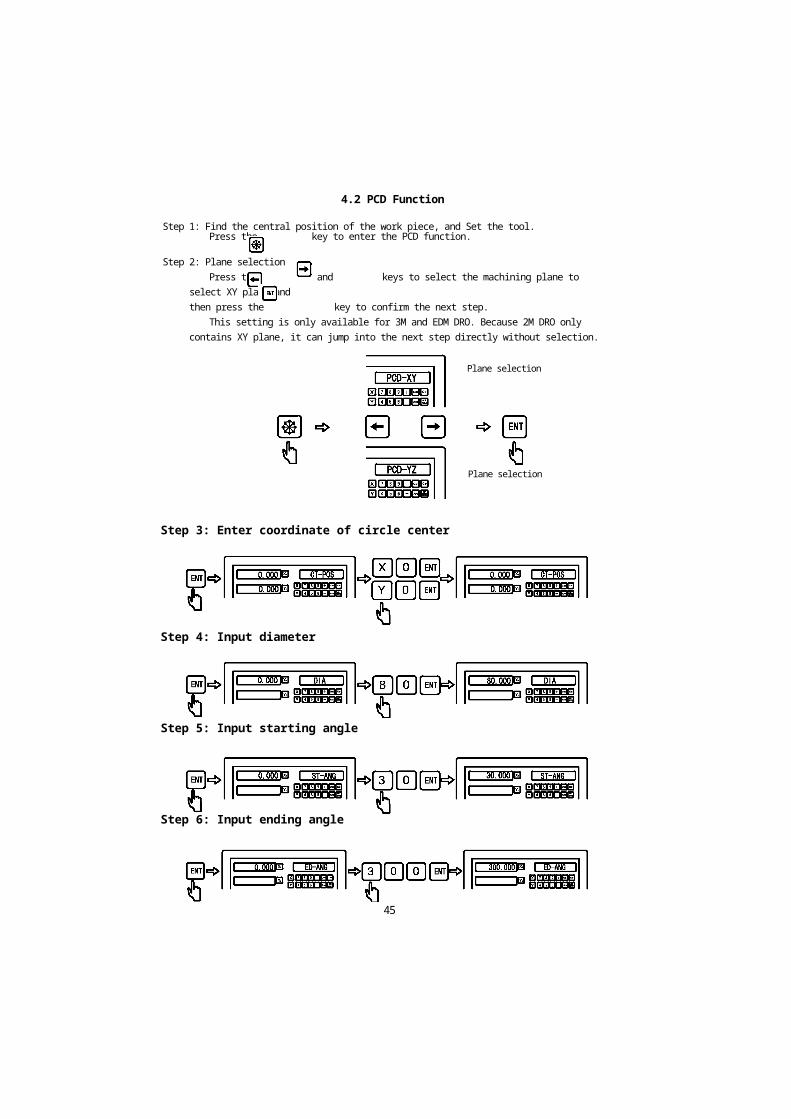
Step 1: Find the central position of the work piece, and Set the tool.Press the key to enter the PCD function.
Step 2: Plane selectionPress the and keys to select the machining plane to select XY plane and
then press the key to confirm the next step.This setting is only available for 3M and EDM DRO. Because 2M DRO only
contains XY plane, it can jump into the next step directly without selection.
Step 3: Enter coordinate of circle center
Step 4: Input diameter
Step 5: Input starting angle
Step 6: Input ending angle
Plane selection
Plane selection
45

4.2 PCD Function
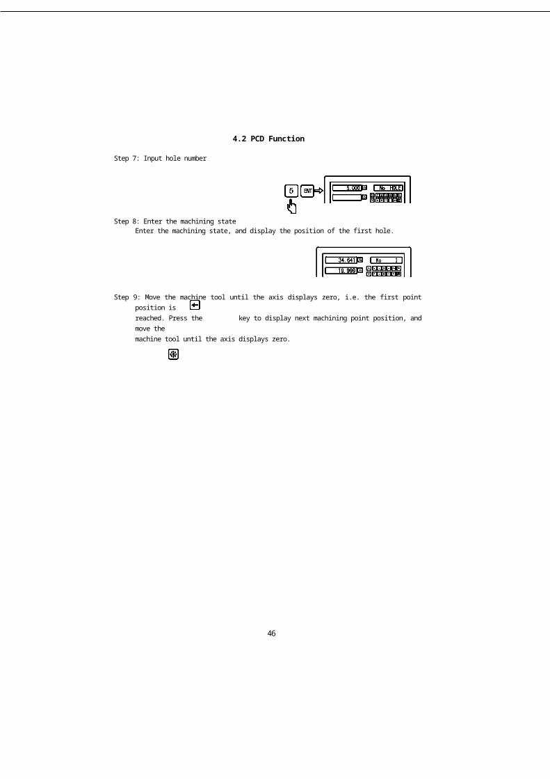
Step 7: Input hole number
Step 8: Enter the machining stateEnter the machining state, and display the position of the first hole.
Step 9: Move the machine tool until the axis displays zero, i.e. the first point position isreached. Press the key to display next machining point position, and move themachine tool until the axis displays zero.
Step 10: Press the key to exit the PCD function anytime.
46

4.3 Smooth R Function
Smooth R Function
47

4.3 Smooth R Function
4.3 Smooth R function(For 2M and 3M Digital Readout (DRO)
Function:When a milling machine is used, especially in the process of machining a mold,
arc often needs to be machined on a work piece. If the arc surface is complex, or alot of round angles need to be machined, or the arc or round angle needs to beaccurately machined, a CNC milling machine should be utilized.
But in the daily machining process, only a simple arc surface or a round angle isneeded with no requirements for the precision of the arc or round angle (particularlyin the process of machining molds). If there is no CNC milling machine in theproduction line, the best way is to machine it with a manual milling machine as itsaves time and efforts, compared to outsourcing it. In the past, an operator used tocalculate the tool positioning in arc machining with a scientific calculator, but thismethod was time-consuming and liable for errors.
DRO provides a simple and easy positioning function for arc cutting tool, so theoperator can perform arc machining in the shortest time. But before you decide touse smooth R function or CNC machining, please bear the following points in mindto make sure smooth R yields the best performance.
The R function group in DRO contains two R functions: smooth R function andsimple R function.
Smooth R function:Smooth R function is a function for full-functional arc machining. The operator
can use the smooth R function to machine all types of most complex arc, even anarc to be connected to another arc (commonly known as R-to-R).
Advantages of smooth R function:Smooth R function can be used to machine the most complex arc or even for
complex machining in R-to-R.
Disadvantages of smooth R function:Operation is complex and the operator needs to know the basic coordinate
system in order to calculate the start point, the end point and the center.
Simple R function:As most arcs machined with a manual milling machine are very simple, and the
operator may machine just one or two simple arcs with the manual milling machinein a month, DRO provides simple R function so that arc machining can be done in asimple and straightforward way without any calculation.
Disadvantages of simple R function:Simple R function can only machine eight types of common arcs, and cannot
machine relatively complex types of arc.
48

4.3 Smooth R Function
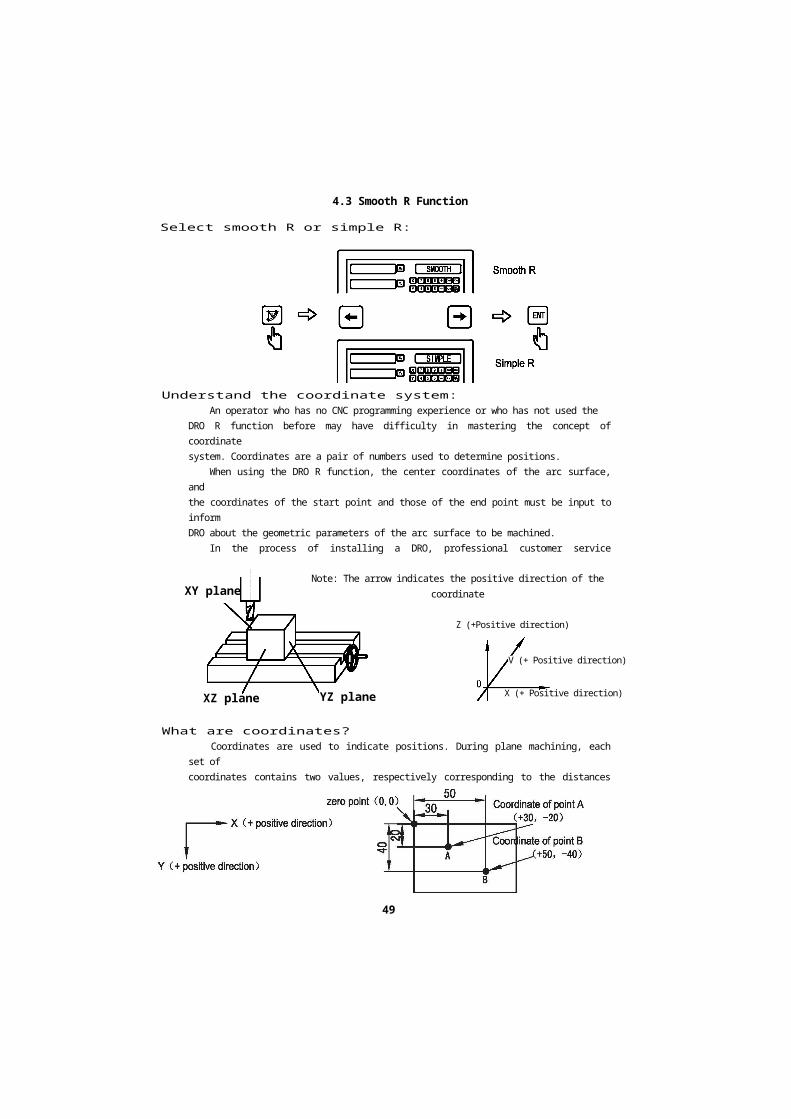
Select smooth R or simple R:
Understand the coordinate system:An operator who has no CNC programming experience or who has not used the
DRO R function before may have difficulty in mastering the concept of coordinatesystem. Coordinates are a pair of numbers used to determine positions.
When using the DRO R function, the center coordinates of the arc surface, andthe coordinates of the start point and those of the end point must be input to informDRO about the geometric parameters of the arc surface to be machined.
In the process of installing a DRO, professional customer service installers willgenerally set the display orientation in the same direction as the machine axis. In ageneral milling machine, the dial direction is shown as below. Therefore, the DROdisplay direction will normally be set as follows.
XY planeNote: The arrow indicates the positive direction of the coordinate
(Running direction of the tool relative to the table )
XZ plane YZ plane
What are coordinates?Coordinates are used to indicate positions. During plane machining, each set of
coordinates contains two values, respectively corresponding to the distances fromthe zero point on the plane. The following is a simple example.
49
Z (+Positive direction)
V (+ Positive direction)
X (+ Positive direction)


4.3 Smooth R Function
Example 2:
Coordinate of point A(+30, +40)Coordinate of point B(+50, +20)
zero point (0, 0)
Example 3:
Working zero point starting point (20,0)(0,0)
starting point.(-20.0) Working zero fx>int
ending point (40,-20)
central point (20,-20)
During the machining process, the coordinate of the machine tool are shown inthe figure below, and the indication of the machining plane is shown in the figure.
\
50
Example 4:
Z (+ positive direction)Y (+ positive direction)
X (+ positive direction)


4.3 Smooth R Function
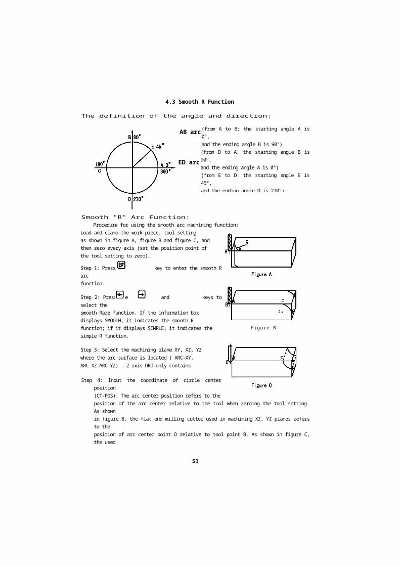
The definition of the angle and direction:
(from A to B: the starting angle A is 0°,and the ending angle B is 90°)(from B to A: the starting angle B is 90°,and the ending angle A is 0°)(from E to D: the starting angle E is 45°,and the ending angle D is 270°)(from D to E: the starting angle D is 270°,and the ending angle E is 45°)
Smooth "R" Arc Function:Procedure for using the smooth arc machining function:
Load and clamp the work piece, tool settingas shown in figure A, figure B and figure C, andthen zero every axis (set the position point ofthe tool setting to zero).
Step 1: Press the key to enter the smooth R arcfunction.
Step 2: Press the and keys to select thesmooth Rare function. If the information boxdisplays SMOOTH, it indicates the smooth Rfunction; if it displays SIMPLE, it indicates thesimple R function.
Step 3: Select the machining plane XY, XZ, YZwhere the arc surface is located ( ARC-XY,ARC-XZ.ARC-YZ) . 2-axis DRO only containsXY plane.
Step 4: Input the coordinate of circle center position(CT-POS). The arc center position refers to theposition of the arc center relative to the tool when zeroing the tool setting. As shownin figure B, the flat end milling cutter used in machining XZ, YZ planes refers to theposition of arc center point O relative to tool point B. As shown in figure C, the usedarc milling cutter refers to the position of arc center point O relative to the toolpoint C.
Step 5: Input the arc radius R.
Figure B
AB arc
ED arc
51


4.3 Smooth R Function
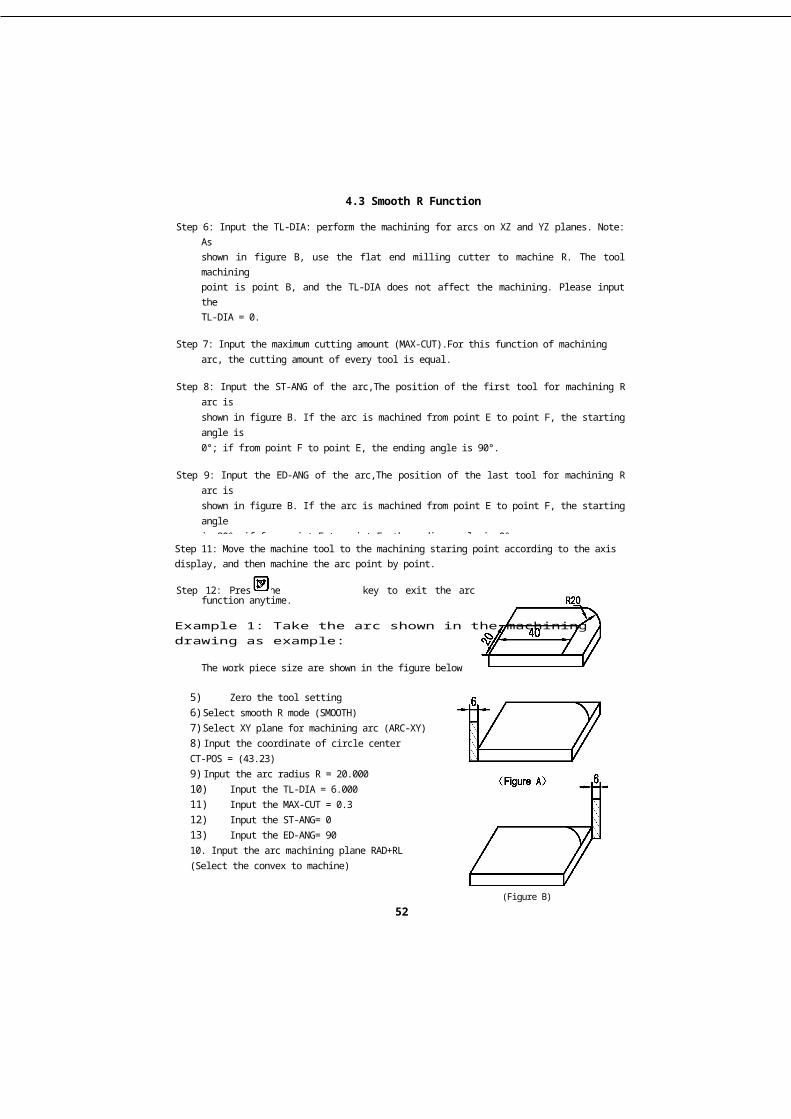
5)Zero the tool setting6) Select smooth R mode (SMOOTH)7) Select XY plane for machining arc (ARC-XY)8) Input the coordinate of circle centerCT-POS = (43.23)9) Input the arc radius R = 20.00010) Input the TL-DIA = 6.00011) Input the MAX-CUT = 0.312) Input the ST-ANG= 013) Input the ED-ANG= 9010. Input the arc machining plane RAD+RL(Select the convex to machine)
(Figure B)52
Step 6: Input the TL-DIA: perform the machining for arcs on XZ and YZ planes. Note: Asshown in figure B, use the flat end milling cutter to machine R. The tool machiningpoint is point B, and the TL-DIA does not affect the machining. Please input theTL-DIA = 0.
Step 7: Input the maximum cutting amount (MAX-CUT).For this function of machiningarc, the cutting amount of every tool is equal.
Step 8: Input the ST-ANG of the arc,The position of the first tool for machining R arc isshown in figure B. If the arc is machined from point E to point F, the starting angle is0°; if from point F to point E, the ending angle is 90°.
Step 9: Input the ED-ANG of the arc,The position of the last tool for machining R arc isshown in figure B. If the arc is machined from point E to point F, the starting angleis 90°; if from point F to point E, the ending angle is 0°.
Step 10: Determine the machining plane of the arc (RAD-RL concave)(RAD+RL convex)The convex machining of arc plane is shown in figure B, and the concave machiningof arc plane is shown in figure C. Press the Q and Q keys to select the convexmachining or concave machining.
Step 11: Move the machine tool to the machining staring point according to the axisdisplay, and then machine the arc point by point.
Step 12: Press the key to exit the arc function anytime.
Example 1: Take the arc shown in the machiningdrawing as example:
The work piece size are shown in the figure below


4.3 Smooth R Function
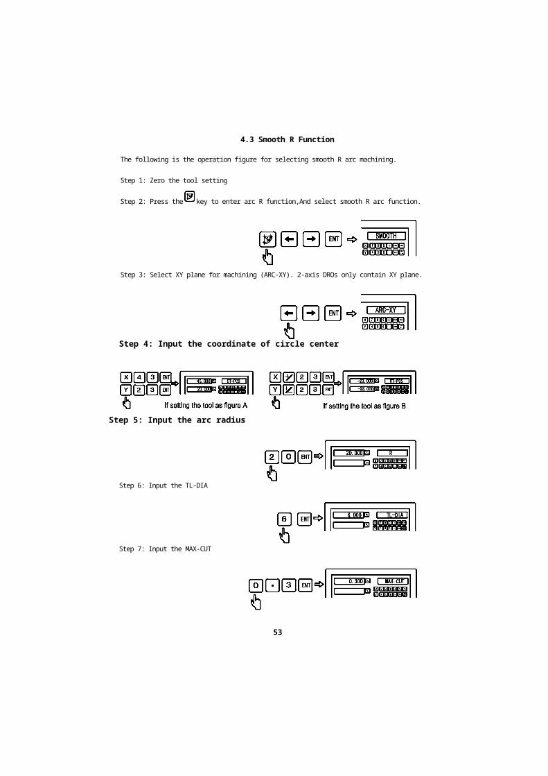
The following is the operation figure for selecting smooth R arc machining.
Step 1: Zero the tool setting
Step 2: Press the key to enter arc R function,And select smooth R arc function.
Step 3: Select XY plane for machining (ARC-XY). 2-axis DROs only contain XY plane.
Step 4: Input the coordinate of circle center
Step 6: Input the TL-DIA
Step 7: Input the MAX-CUT
53
Step 5: Input the arc radius


4.3 Smooth R Function
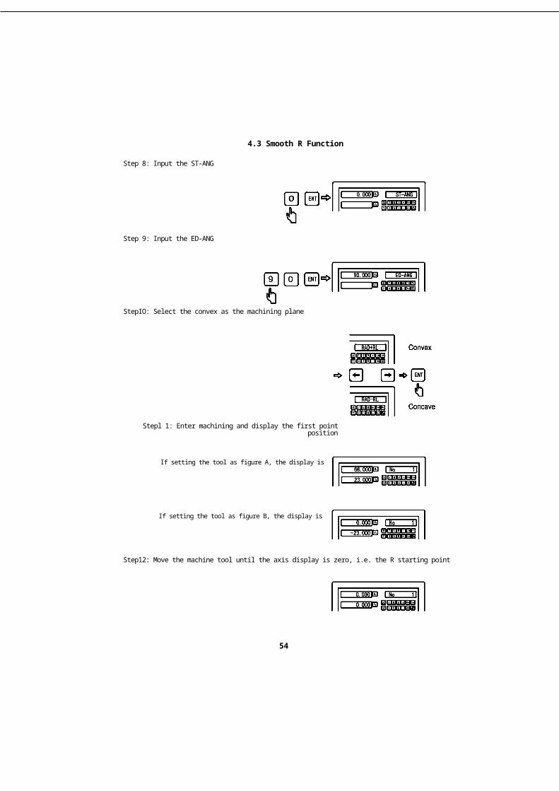
Step 8: Input the ST-ANG
Step 9: Input the ED-ANG
StepIO: Select the convex as the machining plane
Step12: Move the machine tool until the axis display is zero, i.e. the R starting point
54
Stepl 1: Enter machining and display the first point position
If setting the tool as figure A, the display is
If setting the tool as figure B, the display is


4.3 Smooth R Function
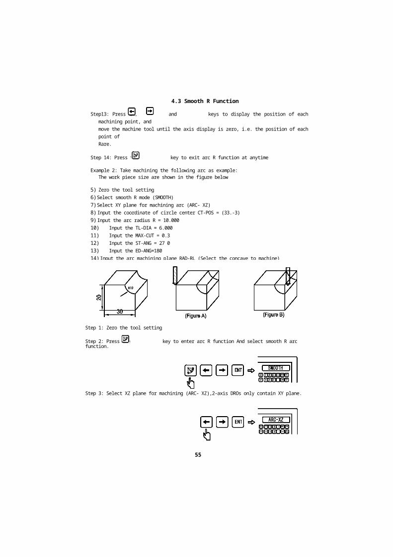
Step13: Press the and keys to display the position of each machining point, andmove the machine tool until the axis display is zero, i.e. the position of each point ofRare.
Step 14: Press the key to exit arc R function at anytime
Example 2: Take machining the following arc as example:The work piece size are shown in the figure below
5)Zero the tool setting6) Select smooth R mode (SMOOTH)7) Select XY plane for machining arc (ARC- XZ)8) Input the coordinate of circle center CT-POS = (33.-3)9) Input the arc radius R = 10.00010) Input the TL-DIA = 6.00011) Input the MAX-CUT = 0.312) Input the ST-ANG = 27 013) Input the ED-ANG=18014) Input the arc machining plane RAD-RL (Select the concave to machine)
Step 1: Zero the tool setting
Step 2: Press the key to enter arc R function And select smooth R arc function.
Step 3: Select XZ plane for machining (ARC- XZ),2-axis DROs only contain XY plane.
55


4.3 Smooth R Function
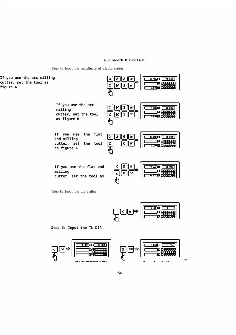
Step 4: Input the coordinate of circle center
If you use the arc millingcutter, set the tool as figure A
If you use the arc millingcutter, set the tool as figure B
If you use the flat end millingcutter, set the tool as figure A
If you use the flat end millingcutter, set the tool as figure B
Step 5: Input the arc radius
Step 6: Input the TL-DIA
woe uic aio ii iiuiii^ uuiici use me Tiai ena mining cuner
56


4.3 Smooth R Function
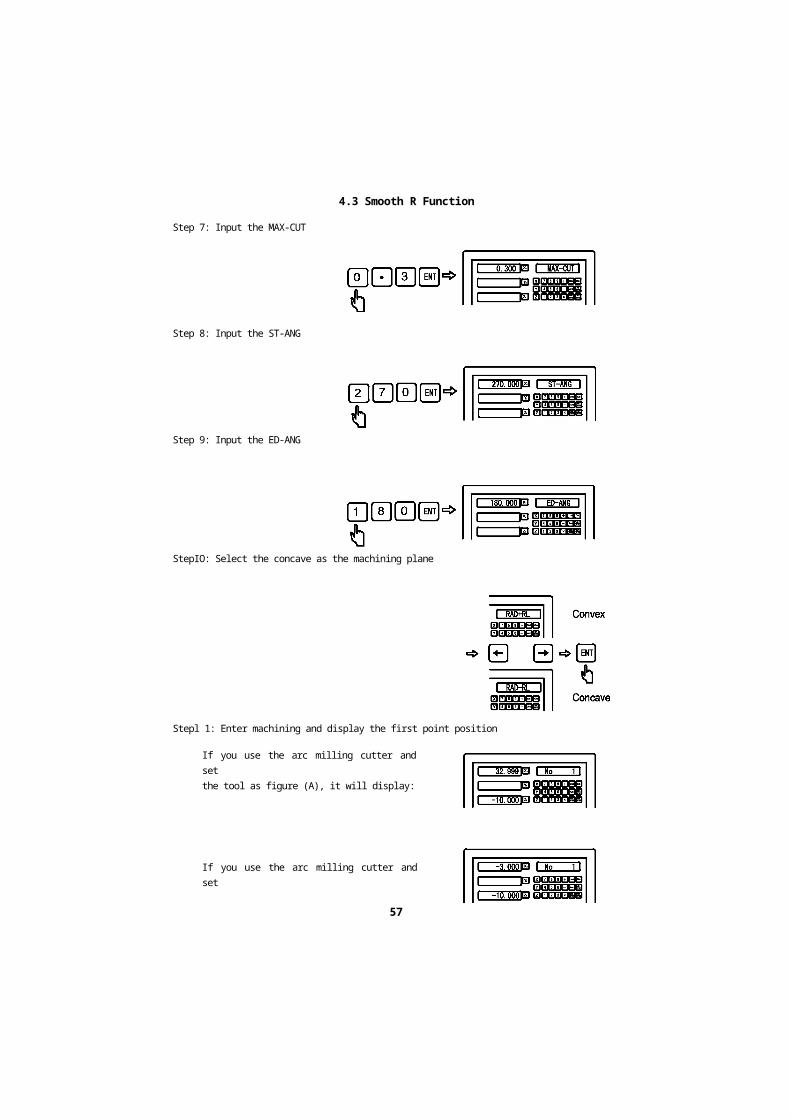
Step 7: Input the MAX-CUT
Step 8: Input the ST-ANG
Step 9: Input the ED-ANG
StepIO: Select the concave as the machining plane
Stepl 1: Enter machining and display the first point position
If you use the arc milling cutter and setthe tool as figure (A), it will display:
If you use the arc milling cutter and setthe tool as figure (B), it will display:
57


4.3 Smooth R Function
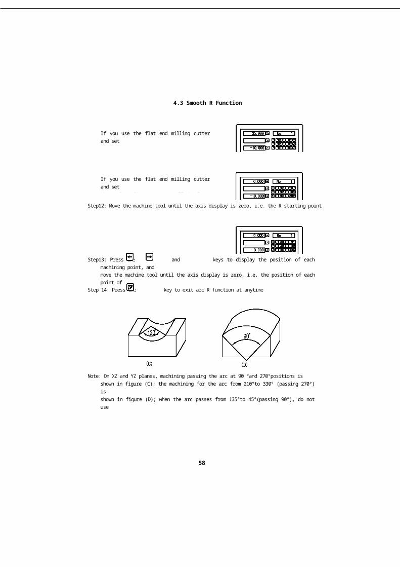
If you use the flat end milling cutter and setthe tool as figure (A), it will display:
If you use the flat end milling cutter and setthe tool as figure (B), it will display:
Step13: Press the and keys to display the position of each machining point, andmove the machine tool until the axis display is zero, i.e. the position of each point ofRare.
Note: On XZ and YZ planes, machining passing the arc at 90 °and 270°positions isshown in figure (C); the machining for the arc from 210°to 330° (passing 270°) isshown in figure (D); when the arc passes from 135°to 45°(passing 90°), do not usethe flat end milling cutter for the machining.
58
Step12: Move the machine tool until the axis display is zero, i.e. the R starting point
Step 14: Press the key to exit arc R function at anytime


4.3 Smooth R Function
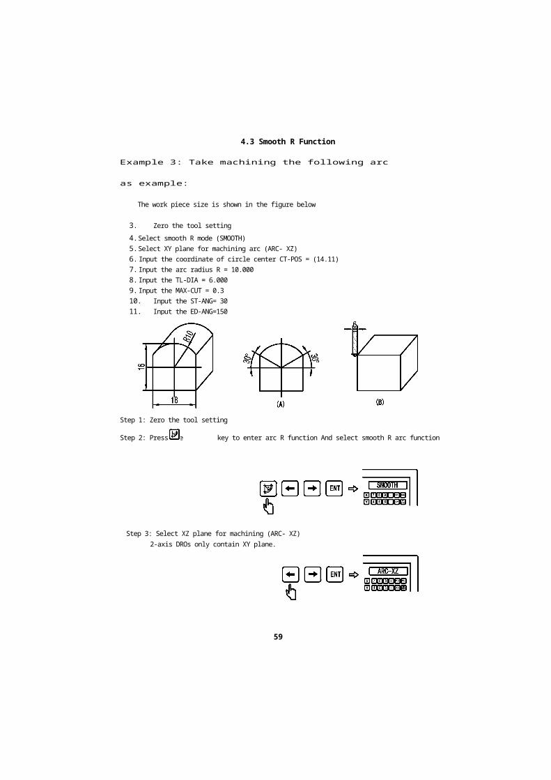
Example 3: Take machining the following arc as
example:
The work piece size is shown in the figure below
3. Zero the tool setting4. Select smooth R mode (SMOOTH)5. Select XY plane for machining arc (ARC- XZ)6. Input the coordinate of circle center CT-POS = (14.11)7. Input the arc radius R = 10.0008. Input the TL-DIA = 6.0009. Input the MAX-CUT = 0.310. Input the ST-ANG= 3011. Input the ED-ANG=150
Step 1: Zero the tool setting
Step 2: Press the key to enter arc R function And select smooth R arc function
Step 3: Select XZ plane for machining (ARC- XZ)2-axis DROs only contain XY plane.
59


4.3 Smooth R Function
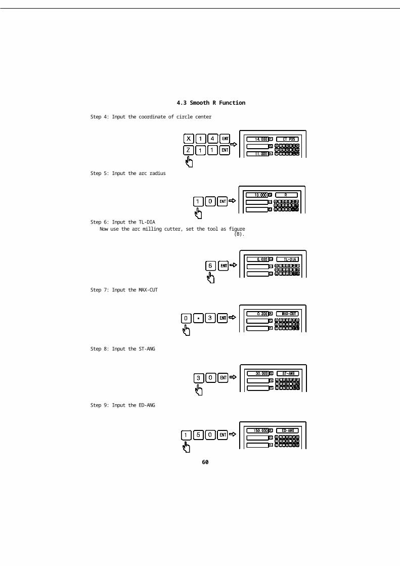
Step 4: Input the coordinate of circle center
Step 6: Input the TL-DIANow use the arc milling cutter, set the tool as figure (B).
Step 7: Input the MAX-CUT
Step 8: Input the ST-ANG
60
Step 9: Input the ED-ANG
Step 5: Input the arc radius


4.3 Smooth R Function
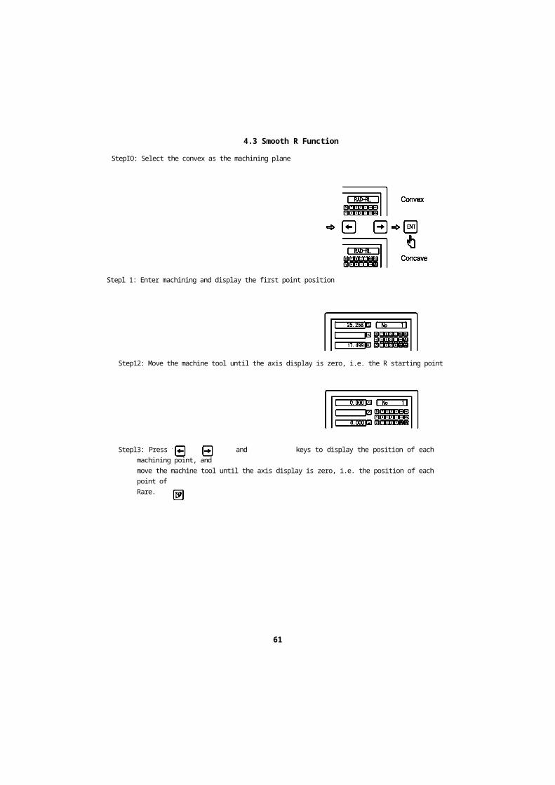
StepIO: Select the convex as the machining plane
Stepl 1: Enter machining and display the first point position
Step12: Move the machine tool until the axis display is zero, i.e. the R starting point
Stepl3: Press the and keys to display the position of each machining point, andmove the machine tool until the axis display is zero, i.e. the position of each point ofRare.
Step 14: Press the key to exit arc R function at anytime
61


4.4 Simple R function
Simple R function
62

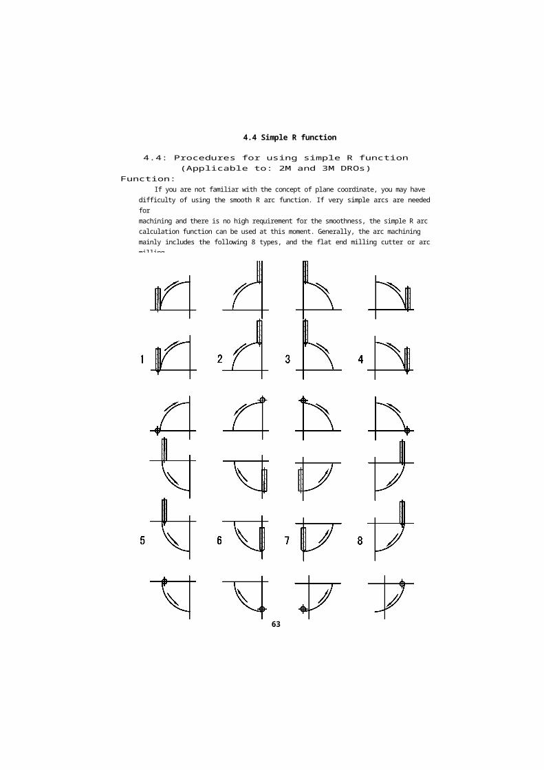
4.4 Simple R function
4.4: Procedures for using simple R function(Applicable to: 2M and 3M DROs)
Function:If you are not familiar with the concept of plane coordinate, you may have
difficulty of using the smooth R arc function. If very simple arcs are needed formachining and there is no high requirement for the smoothness, the simple R arccalculation function can be used at this moment. Generally, the arc machiningmainly includes the following 8 types, and the flat end milling cutter or arc millingcutter is used for the machining.
63


4.4 Simple R function
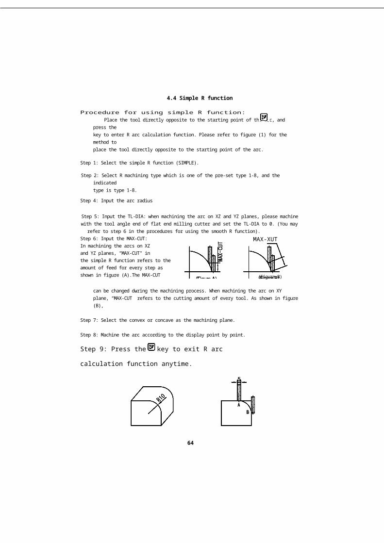
Procedure for using simple R function:Place the tool directly opposite to the starting point of the arc, and press the
key to enter R arc calculation function. Please refer to figure (1) for the method toplace the tool directly opposite to the starting point of the arc.
Step 1: Select the simple R function (SIMPLE).
Step 2: Select R machining type which is one of the pre-set type 1-8, and the indicatedtype is type 1-8.
Step 3: Select XY, XZ and YZ plane for machining (ARC-XY, ARC-XZ, ARC-YZ).
Step 4: Input the arc radius
Step 5: Input the TL-DIA: when machining the arc on XZ and YZ planes, please machinewith the tool angle end of flat end milling cutter and set the TL-DIA to 0. (You may
refer to step 6 in the procedures for using the smooth R function).Step 6: Input the MAX-CUT:In machining the arcs on XZand YZ planes, “MAX-CUT" inthe simple R function refers to theamount of feed for every step asshown in figure (A).The MAX-CUT \i iijuic r\j
can be changed during the machining process. When machining the arc on XYplane, “MAX-CUT” refers to the cutting amount of every tool. As shown in figure (B),the cutting amount for every tool is equal.
Step 7: Select the convex or concave as the machining plane.
Step 8: Machine the arc according to the display point by point.
Step 9: Press the key to exit R arc calculation
function anytime.
Example 1: Take machining the arc shown in
64
(Figure B)
MAX-XUT


4.4 Simple R function
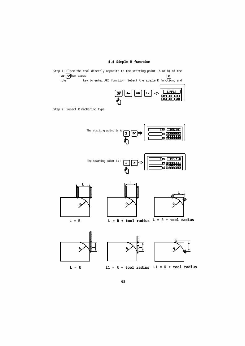
Step 1: Place the tool directly opposite to the starting point (A or B) of the arc, then pressthe key to enter ARC function. Select the simple R function, and press thekey for confirmation.
Step 2: Select R machining type
The starting point is A
The starting point is B
L = R L = R + tool radius
L = R L1 = R + tool radius
65
L = R + tool radius
L1 = R + tool radius


4.4 Simple R function
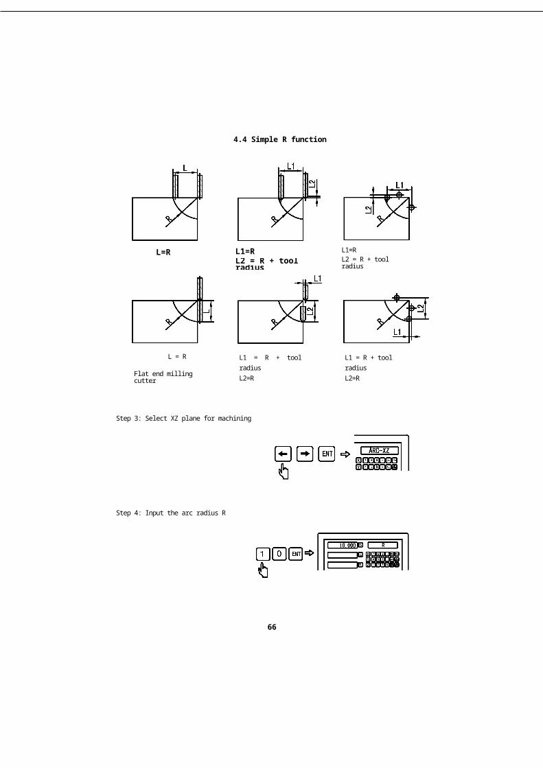
L=R
L = R
Flat end milling cutter
L1=RL2 = R + tool radius
L1 = R + tool radiusL2=RArc milling cutter
L1=RL2 = R + tool radius
L1 = R + tool radiusL2=RXY plane
Step 3: Select XZ plane for machining
Step 4: Input the arc radius R
66


4.4 Simple R function
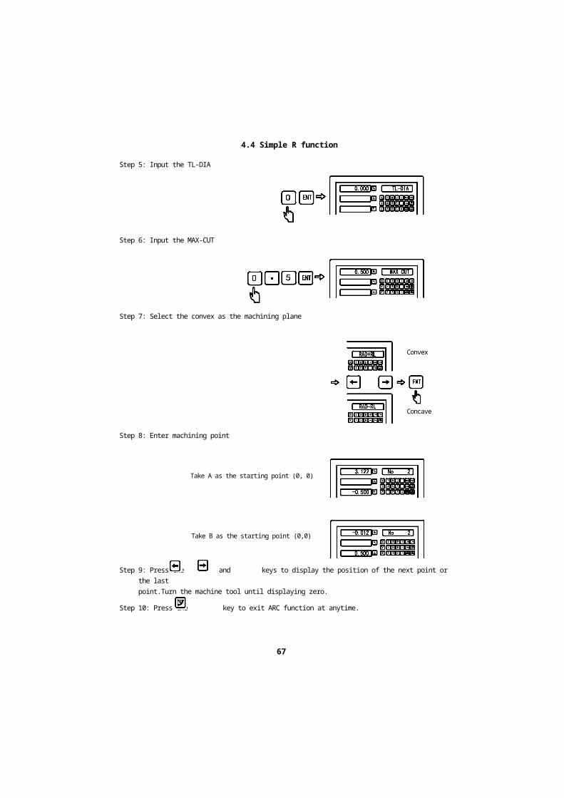
Step 5: Input the TL-DIA
Step 6: Input the MAX-CUT
Step 7: Select the convex as the machining plane
Step 8: Enter machining point
Take A as the starting point (0, 0)
Take B as the starting point (0,0)
Step 9: Press the and keys to display the position of the next point or the lastpoint.Turn the machine tool until displaying zero.
Step 10: Press the key to exit ARC function at anytime.
67
Convex
Concave


4.4 Simple R function
Example 2: Take machining the arc shown in the figure as example:
Step 1: Place the tool directly opposite to the starting point (A or B) of the arc, then pressthe key to enter ARC function.Select the simple R function, and press the keyfor confirmation.
Step 2: Select R machining type
The starting point is A
The starting point is B
Step 3: Select XZ plane for machining
Step 4: Input the arc radius R
68


4.4 Simple R function
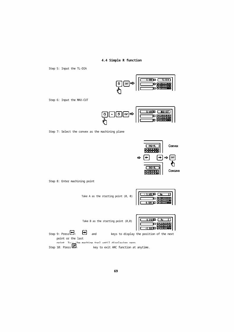
Step 5: Input the TL-DIA
Step 6: Input the MAX-CUT
Step 7: Select the convex as the machining plane
Step 8: Enter machining point
Take A as the starting point (0, 0)
Take B as the starting point (0,0)
Step 9: Press the and keys to display the position of the next point or the lastpoint. Turn the machine tool until displaying zero.
Step 10: Press the key to exit ARC function at anytime.
69


4.5 Rectangle Chambering
Rectangle Chambering
70

4.5 Rectangle Chambering
4.5 Rectangle Chambering(Applicable to: milling machine)
For machining the work piece chamber shown in figure A, the chamberingfunction may be used. Operators can operate conveniently following the prompts.Shown in figure B, the machining starts from the chamber center and proceedsalong the direction indicated by the arrow. The machining can be finished only aftersimple 11 steps. The completion of the machining is shown in figure C. From infigure C, the machined part is just the external rim of the chamber, so operatorsneed to cut off the uncut part from the chamber center manually.
iitjuie \r^f ngure [D)
Example: For machining the work piece shown in figure A, the operatingprocedures are as follows
1: Set the tool according to the position shown in figure A, and zero, then press thekey to enter the chambering function.2: Input the TL-DIA =6.3: Select the XY plane as the machining plane (2-axis DROs do not containthisselection).4: Input the chamber central position CT-POS (78.00, 53.000).5: Input the chamber SIZE (75.000,60.000).6: Enter the machining state.
71
figure (C)


4.5 Rectangle Chambering
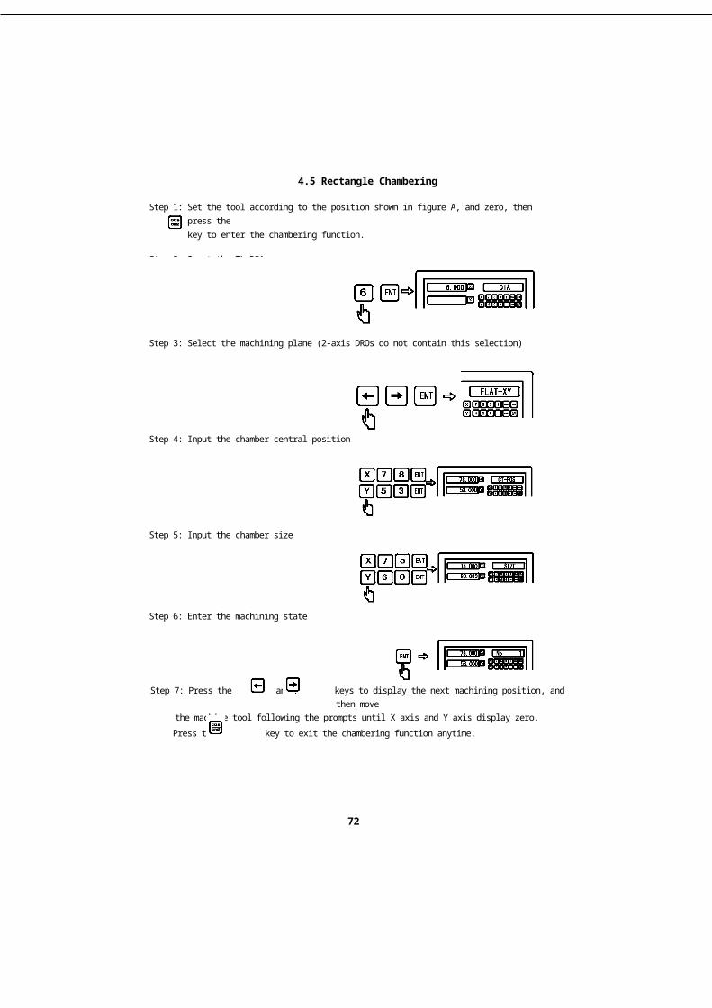
Step 1: Set the tool according to the position shown in figure A, and zero, then press thekey to enter the chambering function.
Step 2: Input the TL-DIA
Step 3: Select the machining plane (2-axis DROs do not contain this selection)
Step 4: Input the chamber central position
Step 5: Input the chamber size
Step 6: Enter the machining state
Step 7: Press the and keys to display the next machining position, and then movethe machine tool following the prompts until X axis and Y axis display zero.
Press the key to exit the chambering function anytime.
72


4.6 Bevel Machining
Bevel Machining
73

4.6 Bevel Machining
4.6 Bevel Machining function(Applicable to: milling machine)
For machining a large bevel, it's very easy and simple with the help of bevelmachining function. However, the bevel machining function only offers XY planemachining.
一. Inclination Correction on the BevelWhen machining the work pieces shownin figure (A) on XY plane, firstly correct theinclination angle of the work pieces before thebevel machining. In this case, the bevelmachining function acts as the inclinationcorrection on the bevel.
Procedures for the inclination correction on the beviFirstly, place the work pieces on the table
roughly according to the desired inclined angle.1.Press the key to enter the bevel machiningfunction.2. Select XY plane as the machining plane.
3. Input the inclined angle.4. Move the table to make the measuring tools(such as the dial indicator) installed and clampedon the milling machine touch point A on thecorrected bevel lightly and set the measuring toolsto zero, then move the table at any distance in thedirection of X axis.5. Press the key to display the value in the direction of Y axis and then move thetable until displaying zero.6. Adjust the work pieces angle, rotate the work pieces by taking point A as thesupporting point to touch the measuring tools and set the measuring tools to zero.
Example: Correct the work piece inclination to 45°shown in figure (B).
Step 1: Place the work piece on the table roughly at 45°. Press the key to enter thebevel machining function.
Step 2: Select the XY plane as the machining plane, (Note: the DRO only offers XYplane).
74
figure (B)
figure (A)


4.6 Bevel Machining
Step 3: Input the bevel angle
Step 4: Move the table in the direction of X axis to make the measuring tools touch thework piece lightly. After setting measuring tools to zero, move the table at anydistance in the direction of X axis.
Step 5: Press the key to calculate the moving distance in the direction of Y axis.Move Y axis until displaying zero.
Step 6: Adjust the work piece angle, and rotate the work piece by taking point A as thesupporting point to make the corrected bevel touch the measuring tools until theangle is at 0°.
Step 7: Move the table until Y axis displays zero.Press the key to exit the bevel machining function anytime.
75

4.7 Calculator
Calculator
76

4.7 Calculator
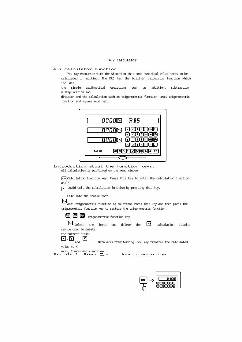
4.7 Calculator FunctionYou may encounter with the situation that some numerical value needs to be
calculated in working. The DRO has the built-in calculator function which includesthe simple arithmetical operations such as addition, subtraction, multiplication anddivision and the calculation such as trigonometric function, anti-trigonometricfunction and square root, etc.
The key layout on the calculator panel:
Introduction about the function keys:All calculation is performed on the menu window
Calculation function key: Press this key to enter the calculation function. While,you could exit the calculation function by pressing this key.
Calculate the square root.
Anti-trigonometric function calculation: Press this key and then press thetrigonometric function key to restore the trigonometric function.
Trigonometric function key.
Delete the input and delete the last calculation result; can be used to deletethe current digit.
and Data axis transferring: you may transfer the calculated value to Xaxis, Y axis and Z axis.
Example 1: Press the key to enter the calculation function


77

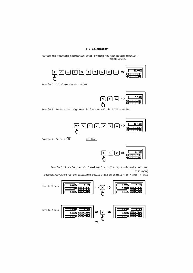
4.7 Calculator
Perform the following calculation after entering the calculation function:10+10+2x5=35
Example 2: Calculate sin 45 = 0.707
Example 3: Restore the trigonometric function ARC sin 0.707 = 44.991
Example 4: Calculation =3.162
Example 5: Transfer the calculated results to X axis, Y axis and Y axis for displayingrespectively,Transfer the calculated result 3.162 in example 4 to X axis, Y axis and
1. axis respectively
78
Move to X axis
Move to Y axis


4.7 Calculator
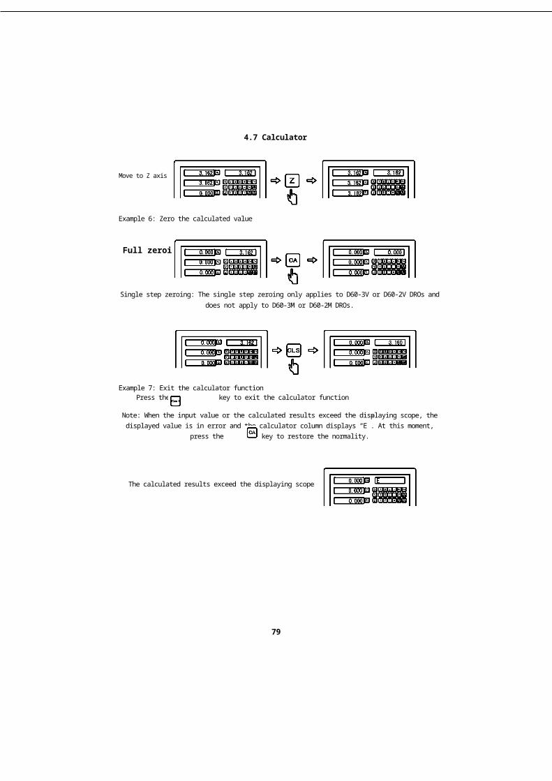
Move to Z axis
Example 6: Zero the calculated value
Full zeroing
Single step zeroing: The single step zeroing only applies to D60-3V or D60-2V DROs anddoes not apply to D60-3M or D60-2M DROs.
Example 7: Exit the calculator functionPress the key to exit the calculator function
Note: When the input value or the calculated results exceed the displaying scope, thedisplayed value is in error and the calculator column displays “E”. At this moment,
press the key to restore the normality.
The calculated results exceed the displaying scope
79


4.8.1 Digital filtering function
Digital filtering function
80

4.8.1 Digital filtering function
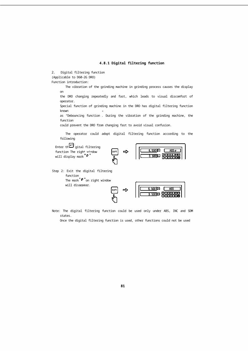
2. Digital filtering function(Applicable to D60-2G DRO)Function introduction:
The vibration of the grinding machine in grinding process causes the display onthe DRO changing repeatedly and fast, which leads to visual discomfort of operator.Special function of grinding machine in the DRO has digital filtering function knownas “Debouncing function”. During the vibration of the grinding machine, the functioncould prevent the DRO from changing fast to avoid visual confusion.
The operator could adopt digital filtering function according to the followingprocedures during grinding process.
Step 1: Press key to enter the digital filtering function
Enter the digital filteringfunction The right windowwill display mark
Step 2: Exit the digital filtering functionThe mark on right windowwill disappear.
Note: The digital filtering function could be used only under ABS, INC and SDM states.Once the digital filtering function is used, other functions could not be usedsimultaneously.
81


4.9.1 200 sets of tool magazine
200 sets of toolmagazine
82

4.9.1 200 sets of tool magazine
4.91 200 sets of tools(Applicable to D60-2L and D60-3L DROs)Function introduction:
Various tools are needed to turn different work pieces or their surface, so wehave to load/unload tools and set tools. To save the operator's time, the lathefunction of the DRO is provided with the function of 200 sets of tool magazine.
Note: The function of 200 sets of tool magazine could only be used togetherwith a tool post on the lathe. Don't use this function without a tool post to avoiderrors in machining.
Basic settings:1. Set a reference tool. After settingthe reference tool, clear Xand Yaxis and set the reference tool atthe ABS zero point.
2. Determine the position of the toolrelative to the reference tool andABS zero point according to thelocation size of the tool and reference tool. As shown in Figure (A), the relativelocation size of tool 2 can be calculated as: X axis 25-30—5, Y axis 20-10=10. Figure (A)
3. Number the tools and store the relative location size of the tool and reference toolinto the DRO.
4. During the machining process,the operator could input anynumber of the called tool andthe DRO will display thelocation size of the currentlycalled tool and ABS zero point.Move the lathe carriage until Xand Y axis display zero.
5. The tool magazine could storematerials of 200 sets of tools.
Figure (B)
83


4.9.1 200 sets of tool magazine
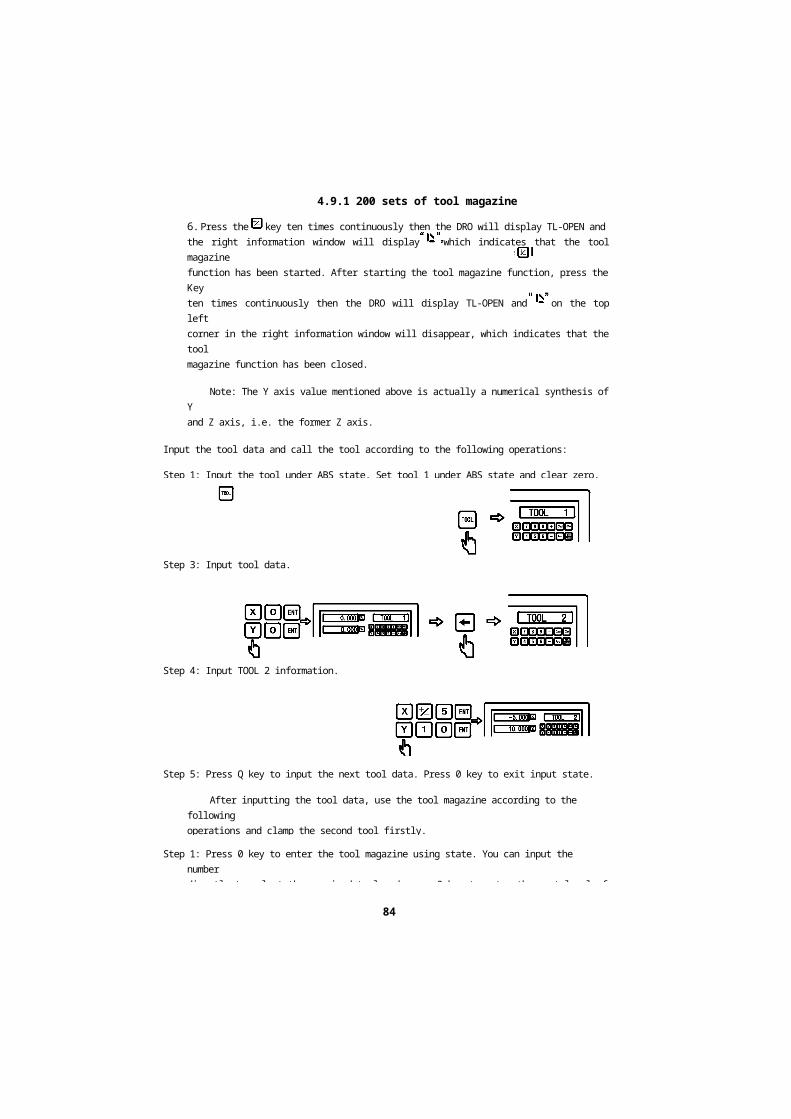
6. Press the key ten times continuously then the DRO will display TL-OPEN andthe right information window will display which indicates that the tool magazinefunction has been started. After starting the tool magazine function, press the Keyten times continuously then the DRO will display TL-OPEN and on the top leftcorner in the right information window will disappear, which indicates that the toolmagazine function has been closed.
Note: The Y axis value mentioned above is actually a numerical synthesis of Yand Z axis, i.e. the former Z axis.
Input the tool data and call the tool according to the following operations:
Step 1: Input the tool under ABS state. Set tool 1 under ABS state and clear zero, thenset tool 1 as the reference tool.
Step 2: Press key to enter the setting state of the tool magazine.
Step 3: Input tool data.
Step 4: Input TOOL 2 information.
Step 5: Press Q key to input the next tool data. Press 0 key to exit input state.
After inputting the tool data, use the tool magazine according to the followingoperations and clamp the second tool firstly.
Step 1: Press 0 key to enter the tool magazine using state. You can input the numberdirectly to select the required tool and press 0 key to enter the next level of menu.
84


4.9.1 200 sets of tool magazine
Step 2: Press and key to select the reference tool relative to the currently usedtool. You could also input the corresponding value to select the reference tool whenthe right window displays BASE state.
Step 3: Press key to exit this function.Move the table until X and Y axis display zero.The second tool has been set at the reference position. Likewise, the operator couldinput and call 200 tools.
Note: You could only zero under ABS state when the used tool (USE) is the same withthe reference tool (BASE) or you can only zero under INC state.
85

4.9.2 Taper measuring
Taper measuring
86

4.9.2 Taper measuring
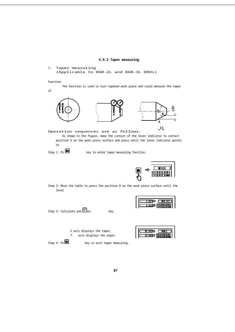
1. Taper measuring(Applicable to D60-2L and D60-3L DROs)
Function:The function is used to turn tapered work piece and could measure the taper of
the work piece in machining.
Operation sequences are as follows:As shown in the figure, make the contact of the lever indicator to contact
position A on the work piece surface and press until the lever indicator points tozero.
Step 1: Press key to enter taper measuring function.
Step 2: Move the table to press the position B on the work piece surface until the leverindicator points to zero.
Step 3: Calculate and press key.
X axis displays the taper.7. axis displays the angle.
Step 4: Press key to exit taper measuring.
87


4.9.3 Diameter /radiusConversion
Diameter/radiusConversion
88

4.9.3 Diameter /radiusConversion
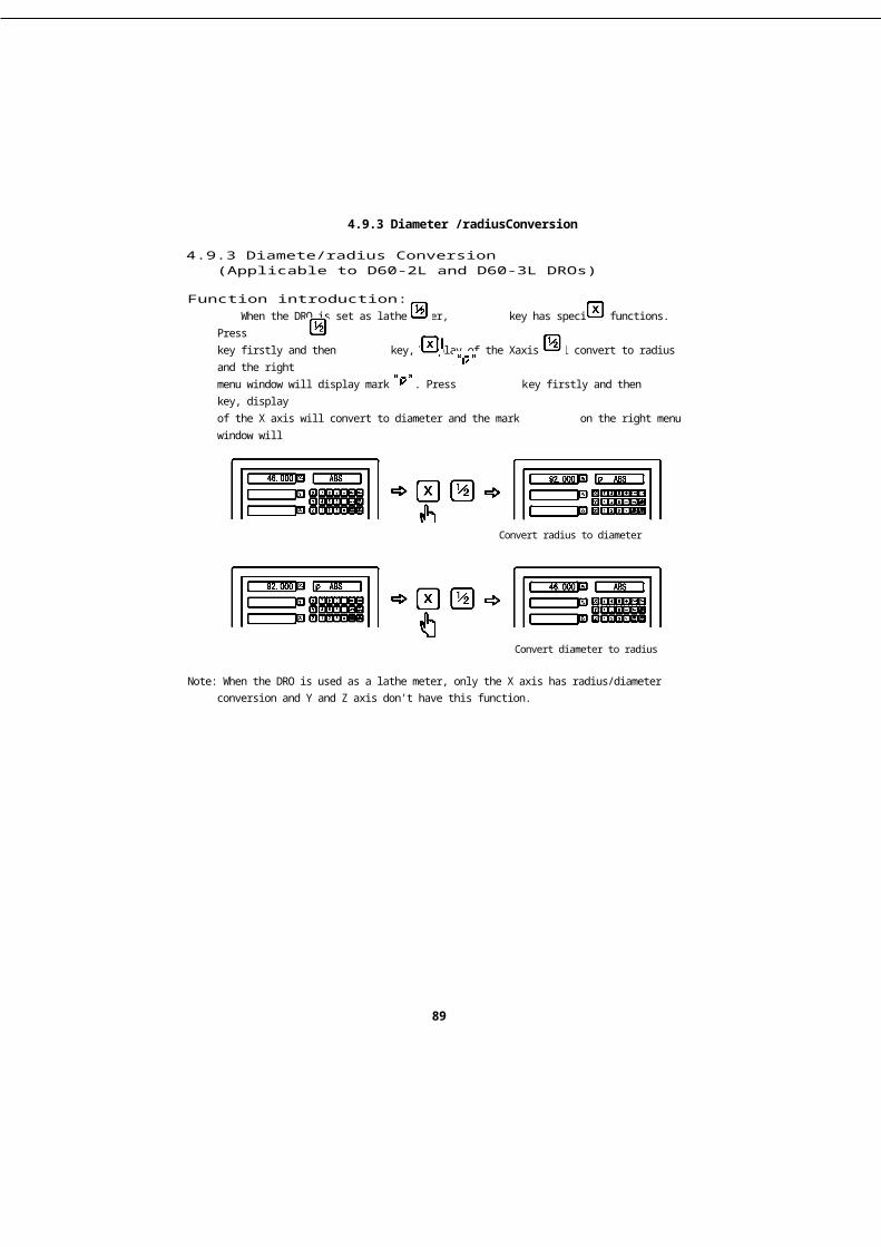
4.9.3 Diamete/radius Conversion(Applicable to D60-2L and D60-3L DROs)
Function introduction:When the DRO is set as lathe meter, key has specific functions. Press
key firstly and then key, display of the Xaxis will convert to radius and the rightmenu window will display mark . Press key firstly and then key, displayof the X axis will convert to diameter and the mark on the right menu window willdisappear.
Example: Radius/diameter
Convert radius to diameter
Convert diameter to radius
Note: When the DRO is used as a lathe meter, only the X axis has radius/diameterconversion and Y and Z axis don't have this function.
89


4.9.3 Diameter /radiusConversion
2. Y + Z function(Applicable to D60-3L DRO)
Function introduction:
When the DRO is used as a 3-axis lathe meter, the calculated value of Y and Zaxis could be combined and displayed on Y axis. Press key, the value of Y andZ axis WILLBE combined and displayed on Y axis and the right menu window willdisplay a mark. Press key again , the mark on the right menu window willdisappear and the display will back to normal.
Example: Y + Z function


90

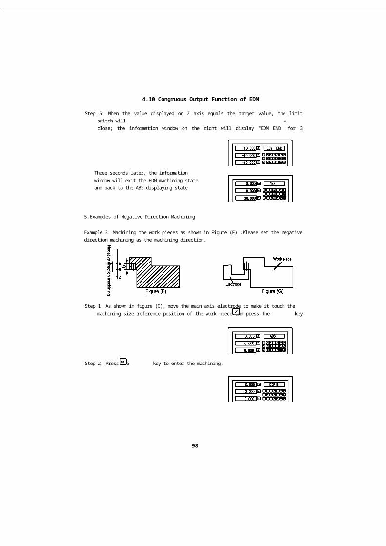
4.10 Congruous Output Function of EDM
Congruous OutputFunction of EDM
91

4.10 Congruous Output Function of EDM
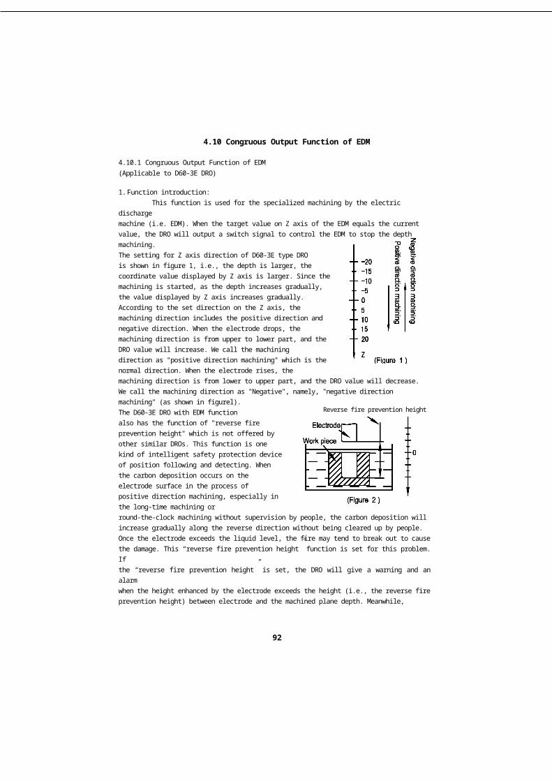
4.10.1 Congruous Output Function of EDM(Applicable to D60-3E DRO)
1. Function introduction:This function is used for the specialized machining by the electric discharge
machine (i.e. EDM). When the target value on Z axis of the EDM equals the currentvalue, the DRO will output a switch signal to control the EDM to stop the depthmachining.The setting for Z axis direction of D60-3E type DROis shown in figure 1, i.e., the depth is larger, thecoordinate value displayed by Z axis is larger. Since themachining is started, as the depth increases gradually,the value displayed by Z axis increases gradually.According to the set direction on the Z axis, themachining direction includes the positive direction andnegative direction. When the electrode drops, themachining direction is from upper to lower part, and theDRO value will increase. We call the machiningdirection as "positive direction machining" which is thenormal direction. When the electrode rises, themachining direction is from lower to upper part, and the DRO value will decrease.We call the machining direction as "Negative", namely, "negative directionmachining" (as shown in figurel).The D60-3E DRO with EDM functionalso has the function of "reverse fireprevention height" which is not offered byother similar DROs. This function is onekind of intelligent safety protection deviceof position following and detecting. Whenthe carbon deposition occurs on theelectrode surface in the process ofpositive direction machining, especially inthe long-time machining orround-the-clock machining without supervision by people, the carbon deposition willincrease gradually along the reverse direction without being cleared up by people.Once the electrode exceeds the liquid level, the fire may tend to break out to causethe damage. This “reverse fire prevention height” function is set for this problem. Ifthe “reverse fire prevention height” is set, the DRO will give a warning and an alarmwhen the height enhanced by the electrode exceeds the height (i.e., the reverse fireprevention height) between electrode and the machined plane depth. Meanwhile,the output signal will shut down the EDM automatically to completely eradicate thechance of fire breaking out. (See figure 2)
Reverse fire prevention height
92


4.10 Congruous Output Function of EDM
2.Specific Operations:
1: Before machining, set the parameters of "reverse fire prevention height", "exitmode", "machining direction" and "EDM mode".
2: Firstly move the main axis electrode of Z axis to make it touch the work piecereference, and then zero Z axis or set the number.
3: Press the key, and input the depth value for machining (the depth value will bedisplayed on Xaxis), such as 10.00, then press the key to confirm. After theconfirmation, press the again to exit "DEPTH" and enter "EDM" state formachining.
4: "The target value of the machining depth" will be displayed on X axis, will bedisplayed on Y axis. The value on Y axis is the machined depth value of the workpiece.will be displayed on Z axis. Note: The value on Z axis is the value of positionwhere the main axis electrode of Z axis is located.
5: After the machining is started, the value displayed on Z axis will get on for the targetvalue gradually. If the electrode rises and drops repeatedly at this moment, thevalue displayed on Z axis will change accordingly. However, the value displayed on8. axis will not change and always indicate the machined depth value.
6: When the value displayed on Z axis equals the target value, the limit switch willclose, and the EDM will stop machining, also, the information screen will display“EDM END”. According to the setting made by the operators, there have two exitmodes: I. Automatic mode. Exit the EDM machining state automatically and restorethe displaying state before machining. II.Pause mode. The screen always shows“EDM END”, and it need to press the key to exit and restore the originaldisplaying state.
I Set the “reverse fire prevention height (ERRHIGH)”, exit mode and machining
Before machining, set the “reverse fire prevention height (ERRHIGH)”, “exitmode” and “machining direction” at first:
Step 1: Zero the coordinate of every axis and then press the key to enter into the“EDM” function. Press the and keys to enter the “EDM" menu setting.
direction:
93


4.10 Congruous Output Function of EDM
Step 2: press the key to enter the setting mode, and set the “reverse fire preventionheight” and input the height value “-150”.
Step 3: Set the positive, negative directions and the current setting is the positivedirection machining.
Negative machining direction (NEGRTIV)Press the key to select
Positive machining direction (POSITIV)Press the n key to select
Step 4: Enter the setting of “exit mode”, and the current setting is “automatic mode”.
Pause mode
Automatic mode
“AUTO” refers to the automatic mode and “STOP” refers to the pause mode. Ifthe original exit mode is “pause mode”, the word “STOP” will appear. Press thekey, the mode could be switched to the "automatic mode”, and the word “AUTO” willappear. For mode selection, you can press the or keys to switch.
Step 5: Select the EDM machining mode, and the current setting is MODE 0.
94


4.10 Congruous Output Function of EDM
Press the key to select MODE 0. The output states of the relay in MODE 0are as follows:
4.8.1When the power is off, the relay coil is OFF.4.8.2When the CPU is not initialized, the relay coil is OFF.4.8.3When the normal state output of booting is 1, the relay coil is ON.4.8.4When EDM function outputs 0 in operation, the relay coil is ON.4.8.5When EDM outputs 0 in depth, the relay coil is OFF.
Press the key to select MODE 1. The output states of the relay in MODE 1are as follows:
4.9.1When the power is off, the relay coil is OFF.4.9.2When the CPU is not initialized, the relay coil is OFF.4.9.3When the normal state output of booting is 0, the relay coil is OFF.4.9.4When EDM function outputs 1 in operation, the relay coil is ON.4.9.5When EDM outputs 0 in depth, the relay coil is OFF.
The machining defaulted by the DRO is the positive direction machining. As inexample 1 and example 2, you should set the positive direction machining as themachining at first in the positive direction machining; as the work piece shown in themachining figure (F), you should set the negative direction machining as themachining direction before machining in the negative direction machining.Otherwise, after entering the machining, the DRO will identify that the machininghas been completed and exit the machining.
Step 6: Press the key to exit the setting to restore the original state.
II Examples of Positive Direction Machining
Example 1: Machining the work piece as shown in Figure (A), The work piece andelectrode are shown in figure (B). Please set the positive direction machining as themachining direction at first.
95


4.10 Congruous Output Function of EDM
Electrode
Work piece
Figure (B)
Step 1: As shown in figure (B), move the main axis electrode to make it touch the workpiece and then press the , and keys to zero.
Step 2: Press the key to enter the machining.
Step 3: Set the machining depth.
Step 4: Start to machine.
Step 5: When the value displayed on Z axis equals the target value, the limit switch willclose; the information window on the right will display “EDM END” for 3 seconds,then back to the state before machining.
Three seconds later, the information windowwill exit the EDM machining state and backto the ABS displaying state.
Figure (A)
Positive direction machining
96


4.10 Congruous Output Function of EDM
Example 2: Machining the work pieces as shown in Figure (C)
Please set the positive direction machining as the machining direction at first.Electrode
Positive direction machining
Figure (D)
Step 1: As shown in figure (D), move the main axis electrode to make it touch themachining size reference position of the work pieces and press the key to zero.
Move the electrode to the positionshown in figure (E)
Step 2: Press the key to enter the machining
Step 3: Set the machining depth
Step 4: Start to machine
Figure (C) Figure (E)


4.10 Congruous Output Function of EDM
Step 5: When the value displayed on Z axis equals the target value, the limit switch willclose; the information window on the right will display “EDM END” for 3 seconds,then back to the state before machining.
Three seconds later, the informationwindow will exit the EDM machining stateand back to the ABS displaying state.
5.Examples of Negative Direction Machining
Example 3: Machining the work pieces as shown in Figure (F) .Please set the negativedirection machining as the machining direction.
Step 1: As shown in figure (G), move the main axis electrode to make it touch themachining size reference position of the work piece and press the key to zero.
Step 2: Press the key to enter the machining.
98


4.10 Congruous Output Function of EDM
Step 3: Set the machining depth.
Step 4: Start to machine.
Step 5: When the value displayed on Z axis equals the target value, the limit switch willclose; the information window on the right will display “EDM END” for 3 seconds,then back to the state before machining.
Three seconds later, the informationwindow will exit the EDM machining stateand back to the ABS displaying state.
6. Use PCD Function together with EDM FunctionIn PCD function, the DRO can call the EDM function to complete the EDM
machining for the PCD. The specific operation procedures are as follows:
1. Press the key to enter the PCD function to set parameters (please refer to thePCD function setting). After setting all parameters, press the key to enter thePCD machining. When displaying the position coordinate of the first machining,move the table to make the electrode aligning the first machining hole.
2. Press the key to input the EDM parameter setting and machining state (refer tothe EDM parameter setting for the EDM parameter setting method), and input themachining depth for EDM machining. After the machining is completed, press thekey to exit EDM machining and enter the PCD machining. Press the key todisplay the position coordinate of the second hole. Move the table to make theelectrode aligning the next machining hole.
99


4.10 Congruous Output Function of EDM
7. Use PLD Function and EDM Function CooperativelyIn PLD function, the DRO can call the EDM function to complete the EDM
machining for the PLD. The specific operation procedures are as follows:
4.10.1 Press the key to enter the PLD function to set parameters (please refer to thePLD function setting). After setting all parameters, press the key to confirmentering the PCD machining. The position of first machining hole is displayed incoordinate. Then move the table to make the electrode aligning the first machininghole.
4.10.2 Press the key to enter the EDM parameter setting and machining state (refer tothe EDM parameter setting for the EDM parameter setting method), and input themachining depth for EDM machining. After the machining is completed, press the
key to exit EDM machining and enter the PLD machining. Press the key todisplay the position coordinate of the second hole. Move the table to make theelectrode aligning the next machining hole.
8. Function of Switching Displaying Mode
In the EDM machining, the operators may press the key if they want to knowthe coordinate condition of external XY plane. If the information window displays“EDM-P”, the values displayed on X axis and Y axis are the values of the externalXY plane. Press the key again to restore the EDM displaying mode. Thisfunction is only limited to switching the displaying mode and does not affect theEDM machining.
9. EQUAL OUT port of rear base plate
The output of EQUAL OUT is the relay output and the contact capacity is:1.0A30VC, 0.5A125VAC, 0.3A60VDC.
9-pins SocketPin Number
Signal type 9-pins lead
1 OFF (NC Port) Black
3 COM (Common Port) Yellow
5 NO (NO Port) Red
100

5. Appendix
5.1Notices for Usage:1. Supply voltage: AC 80 V - - 260 V, 50 - - 60 Hz2. Power: 15 W3. Operating temperature: -10°C- - 60°C4. Storage temperature: -30”C- - 70°C5. Relative humidity (RH): <90% (25)>6. Axis to be displayed : 1 axis, 2-axis and 3-axis7. Input signal allowed by the DRO: TTL square wave8. Allowable input signal frequency: < 5 MHz9. Length resolution: 0.1 um, 0.2 um, 0.5 um, 1 um, 2 um, 2.5 um, 5 um and 10 um10. Minimum resolution of angle display: 0.0001/ pulse11. Weight: 2.2 KG12. Volume size: 300 x 180 x 75 (mm)13. Interface definition of the grating ruler: (DB 9-pins socket)
5.2Installation Figure
Pin 1 2 3 4 5 6 7 8 9
signal NA OV NA NA NA A +5V B R
101


5. Appendix
5.3TroubleshootingThe following troubleshootings are just the preliminary methods. If the problems
still exist, please do not dismantle the DRO by yourself, but contact our company orthe dealers for help in time.
Faults Fault Causes Solutions
The DRO doesn'tdisplay anything
1) The power is not on ?2)The power switch is not closed ?3)The supply voltage is not appropriate4)The internal supply of the gratingruler is in short circuit.
1) Check whether the power lineand power plug are plugged in.2)Close the power switch.3)Make sure the supply voltagebetween 85V-265V.4)Pull out the connector of thegrating ruler.
One axis of the DROdoesn’t count
1.Operate the machine after swappingwith the grating ruler of another axis.2. Some special functions of the DROare being used.
5.1 If counting, it's the fault ofthe grating ruler; if not, it’sthe fault of the DRO.5.2 Exit the special function
The counting of DROis not accurate (itcan’t zero)
1 The grating ruler isn’t installedaccording to the requirements or theaccuracy is not enough.
2 After being used for a long time, thevibration of the machine tool makesthe fixed reading head or the screwsloosen.
3 The accuracy of the machine tool isnot good.4 The DRO resolution isn’t consistentwith the grating ruler.
1. Reinstall the grating ruler andadjust the level.2. Tighten all the fixed screws.3. Overhaul the machine tool.4. Reset the DRO resolution.
The counting ofDRO is in error,Thedisplayed operationdistance isn’tconsistent with theactual distance
1. The machine tool and the DRO shellare not connected to earth.2. The accuracy of the machine tool isnot good.3. The running speed of the machinetool is too fast.4. The grating ruler isn't installedaccording to the requirements and theaccuracy is not enough.5. The DRO resolution isn’t consistentwith the grating ruler.
6. The operating size unit is notconsistent with the displayedMetric/British units.
7. The linear error compensation settingof the DRO is not appropriate.8. The grating ruler exceeds theoperating range of length or the readhead is broken.
1. Connect the machine tool andthe DRO shell to earth.2. Overhaul the machine tool.3. Reduce the running speed ofthe machine tool.4. Reinstall the grating ruler andadjust the level.5. Reset the DRO resolution.
6. Switch the displayedMetric/British units.7. Reset the linear errorcompensation of the DRO.
8. Repair the grating ruler.
102

5. Appendix
Faults Fault Causes Solutions
The grating rulerdoesn’t count
1. The grating ruler exceeds theoperating range of length or the readhead Is broken.2. The read head of grating ruler rubsthe ruler shell leading to the aluminumscraps accumulated.
3. The gap between the read head ofgrating ruler and the ruler body is toowide.
4. The metal tubes of the grating rulerare damaged, which causing theshort circuit or disconnection ininternal wiring.
2. Repair the grating ruler3. Repair the grating ruler4. Repair the grating ruler5. Repair the grating ruler
The grating rulerdoesn’t countsometimes
1. The small box of the grating ruler isseparated from the steel ball.2. The grating glass in the read headof the grating ruler is abraded.3. There is dirt on the grating glass inthe shell of the grating ruler.
4. The elasticity of small box spring inthe read head of the grating ruler isnot enough.
1. Repair the grating ruler2. Repair the grating ruler3. Repair the grating ruler4. Repair the grating ruler
103
