Электродвигатели frank & dvorak ie1
TRANSCRIPT

AUSTRIA

- 2 - ––––––––––––––––––––––––––––––––––––––––––––––––––––––––––––—–––––––––––––––————
INTRODUCTION
FFD offers a full range of low voltage electric motors, single phase motors as well as three phase squirrel cage induction motors for continuous duty. All motors are manufactured according to the ISO 9001 certification. The three phase induction motors in this catalogue are available in the frame sizes 56 to 315 with the outputs 0,06kW to 200kW. We offer the single phase motors in two groups: a.) Motor types NPEKg, NPEKh and NPEg with a low starting torque.
These motors have built on a running capacitor. They are available in the frame sizes 56 to 100 with the outputs 0,04kW to 2,2kW and with the starting torque ratio 0,4 to 1,4.
b.) Motor types FDEB with a high starting torque. These motors have built on a starting and a running capacitor. There is also a centrifugal switch built in it. They are available in the frame sizes 63 to 80 with the outputs 0,12kW to 1,5kW and with the starting torque ratio 1,5 to 2,55.
This catalogue also includes cooling medium pumps of the types DKP and EKP.
CONSTRUCTION OF THE MOTORS
1.) Housing: The housing for motors of the frame sizes 56 to 112 is made of die-casted aluminium alloy. The housing for motors of the frame sizes 132 to 315 is made of cast iron. The feet of the motors are detachable for the frame sizes 56 to 132 as well as the motor series (2)SIE315 while the motors of the frame sizes 160 to 315 have integrated feet.
2.) End-shields and flanges: End-shields and flanges for motors of the frame sizes 56 to 100 are made of aluminium . End-shields and flanges for motors of the frame sizes 112 to 315 are made of cast iron.

––––––––––––––––––––––––––––––––––––––––––––––––––––––––––––––––––––––––––––———— - 3 -
3.) Rotor: The winding of the rotor is made of die-casted aluminium. The rotor together with the shaft is dynamically balanced with half key acc. to DIN ISO 8821.
4.) Terminal boxes: The motors of the frame size 56 to 180 have their terminal box on the top of the housing. The terminal box can be rotated in steps of 90 deg. The motors of the frame size 200 to 315 (DPIG series) have their terminal box on the right side of the housing. Motors with the terminal box on the left side also are available on request. The (2)SIE motor series of the frame size 315 have their terminal box on the top as a standard. Motors with their terminal box on the side (right or left hand side) is available too.
5.) Fan: The fan for the motors of the frame size 56 to 315 is made of plastic. On request the fan for the motors of the frame size 200 to 315 can be made of steel welded construction.
6.) Cooling: The motors are surface cooled (IC411).
7.) Fan cover: The fan cover for all motors is made of sheet steel.
8.) The shaft ends: Motors in their standard version have one shaft end with the dimensions acc. to EN. Shaft ends of the motors of the frame size 63 and above have a drilled and tapped hole. On request, with an extra charge motors are available with a special shaft end and/or two shaft ends too.
9.) Degree of protection: All motors of this catalogue are manufactured with the degree of protection IP 55 (IP…International Protection). On request the motors are available with a higher degree of protection.
IP protection of work equipment protection of people IP protection of work equipment
First prefix
against penetrate of solid foreign bodies
against access of dangerous parts with
Second prefix
against penetrate of water with detrimental action
0. (no protection) (no protection) .0 (no protection)
1. ≥ 50 mm diameter back of the hand .1 drip - proof vertical
2. ≥ 12,5 mm diameter finger .2 drip - proof (15° inclination)
3. ≥ 2,5 mm diameter tool .3 spray - proof
4. ≥ 1,0 mm diameter wire .4 splash - proof
5. dustproof wire .5 jet - proof
6. dust - tight wire .6 strong jet -proof
.7 short-time immersion
.8 permanent immersion
10.) Nominal voltage and frequency: The nominal voltage of three phase motors is 400V at the nominal frequency of 50Hz. Motors for another nominal voltage and/or another nominal frequency are available on request.
- 4 - ––––––––––––––––––––––––––––––––––––––––––––––––––––––––––––—–––––––––––––––————
11.) Nominal output: The motors will properly operate with the nominal output at continuous duty (S1) when the following conditions are observed: - motor is supplied with nominal voltage and frequency - ambient temperature is not higher than + 40°C - altitude of site is up to 1000m above sea level With an ambient temperature higher than + 40°C or an altitude of site higher than 1000m the output on the shaft reduces as follows:
Ambient temperature °C 30 40 45 50 55 60
Rated output reduced to % 100 100 96 90 86 82
Altitude of site m 1.000 1.500 2.000 2.500 3.000 3.500 4.000
Rated output reduced to % 100 97 94 90 86 82 77
Example: The permissible output of a motor rated at 30kW at the ambient temperature of + 55°C at the altitude of
site of 2500m over the sea level amounts to: Pper = 30 x 0,86 x 0,90 = 23kW
12.) Insulation: The standard motors are manufactured in the insulation class F while the motor types SIE 315M8C, SIE 315M8D and (2)SIE 315L… Types are manufactured in the insulation class H.
13.) Options: The motors can be equipped with optional accessories (e.g. PTC, Pt100, anti-condensation heater, external fan), suitable for frequency inverter drive or tacho generator.
14.) Ordering: When ordering motors please specify the following information: a) quantity b) motor size c) nominal output, kW d) rated speed e) type of mounting f) nominal voltage and nominal frequency g) any special features or options

––––––––––––––––––––––––––––––––––––––––––––––––––––––––––––––––––––––––––––———— - 5 -
STANDARDS
Technical information The motors are manufactured in accordance with the following standards:
Subject European Norm (EN) Subject European Norm (EN)
Nominal data EN 60034-1 Direction of rotation EN 60034-8
Losses and efficiency EN 60034-2 Noise limits EN 60034-9
Degree of protection EN 60034-5 Vibration limits EN 60034-14
Methods of cooling EN 60034-6 Mounting dimensions EN 60072-1
Type of mounting EN 60034-7 Losses and efficiency (2)SIE motors EN 60034-2-1
BEARINGS
The exact bearing type for each motor is specified in the table below:
Motor Type of bearing
Size Nr of poles
DE NDE
DPIH 56 2,4 6201 ZZ
DPIH 63 2,4,6,8 6202 ZZ
DPIH 71 2,4,6,8 6203 ZZ
DPIH 80 2,4,6,8 6204 ZZ
DPIH 90 S,L 2,4,6,8 6205 ZZ C3 (6205 2RS at IMV1)
DPIG 100 L 2,4,6,8 6206 ZZ C3 (6206 2RS at IMV1)
DPIG 112 M 2,4,6,8 6306 ZZ C3 (6306 2RS at IMV1)
2DPIG 132S,M 2,4,6,8 6308 ZZ C3 (6308 2RS at IMV1)
DPIG 160 M,L 2,4,6,8 6309 ZZ C3 (6309 2RS at IMV1)
DPIG 180 M,L 2,4,6,8 6311 ZZ C3 (6311 2RS at IMV1)
Standard On request
DE NDE DE / NDE
2DPIG 200 2 6312 C3 6312 C3 --
2DPIG 200 4,6,8 6312 C3 6312 C3 NU 312 / 6312 C3
2DPIG 225 2 6313 C3 6313 C3 --
2DPIG 225 4,6,8 6313 C3 6313 C3 NU 313 / 6313 C3
2DPIG 250 2 6315 C3 6315 C3 --
2DPIG 250 4,6,8 6315 C3 6315 C3 NU 315 / 6315 C3
2DPIG 280 2 6315 C3 6315 C3 --
2DPIG 280 4,6,8 6317 C3 6317 C3 NU 317 / 6317 C3
DPIG 315 2 6315 C3 6315 C3 --
DPIG 315 4,6,8 6318 C3 6318 C3 NU 318 / 6318 C3
2SIE 315 MC 2 6315 C3 6315 C3 --
(2)SIE315 MC,D 4,6,8 6320 C3 6318 C3 NU 320 / 6318 C3
2SIE 315L 2 6317 C3 6317 C3 --
(2)SIE 315L 4,6,8 6322 C3 6322 C3 NU 322 / 6322 C3
We reserve the right to change the bearing type due to modifications!

- 6 - ––––––––––––––––––––––––––––––––––––––––––––––––––––––––––––—–––––––––––––––————
TYPES OF MOUNTING
according to IEC CODE I / IEC CODE II

––––––––––––––––––––––––––––––––––––––––––––––––––––––––––––––––––––––––––––———— - 7 -
Performance data of three phase motors
We reserve the right to change technical data or dimensions due to modifications!
Typ
e
Rat
ed s
peed
Nom
inal
out
put
Nom
inal
cur
rent
in A
at
Effi
cien
cy η
in %
Pow
er fa
ctor
cosϕ
Nom
inal
torq
ue T
N
Sta
rt /
nom
inal
torq
ue
(DO
L)
Sta
rt /
nom
inal
cur
rent
(DO
L)
Bre
ak d
own
/
nom
inal
torq
ue
Sou
nd p
ress
ure
leve
l
Mom
ent o
f ine
rtia
Wei
ght i
n B
3
min-1 kW HP 380V 400V 4 / 4 3 / 4 2 / 4 4 / 4 Nm TS/TN IS/IN TB/TN dB(A) kgm² kg
2 pole; 50 Hz; 3000 min-1
DPIH 56 A/2 2820 0,09 0,12 0,35 0,33 62,0 50,0 43,0 0,63 0,30 2,5 3,4 2,7 60 0,000076 2,90
DPIH 56 B/2 2800 0,12 0,17 0,42 0,40 65,0 58,0 50,0 0,73 0,41 2,0 3,0 2,0 60 0,000095 3,20
DPIH 63 A/2 2760 0,18 0,25 0,53 0,50 65,0 63,0 58,0 0,80 0,623 2,1 3,4 2,1 60 0,000175 3,50
DPIH 63 B/2 2780 0,25 0,33 0,68 0,65 72,0 65,0 62,0 0,80 0,865 2,4 3,3 2,5 60 0,000235 4,20
DPIH 71 A/2 2800 0,37 0,5 1,05 1,00 71,0 69,0 67,0 0,77 1,262 2,2 4,4 2,2 60 0,000389 5,00
DPIH 71 B/2 2790 0,55 0,75 1,42 1,35 75,0 72,0 69,0 0,82 1,883 2,0 4,0 2,1 60 0,000484 6,00
DPIH 80 A / 2 2800 0,75 1,00 2,00 1,90 74,0 72,0 66,0 0,80 2,56 2,7 4,5 2,6 65 0,000829 7,80
DPIH 80 B / 2 2780 1,10 1,50 2,63 2,50 77,0 75,0 69,0 0,84 3,78 2,6 5,1 2,6 65 0,001005 9,10
DPIH 90 S / 2 I 2835 1,50 2,00 3,40 3,20 81,1 82,1 80,7 0,83 5,10 3,0 6,1 3,0 68 0,0013 14,0
DPIH 90 L / 2 I 2855 2,20 3,00 4,90 4,70 83,2 83,9 82,2 0,82 7,40 3,4 7,1 3,5 68 0,002 16,8
DPIG 100 L / 2 I 2905 3,00 4,00 6,40 6,00 83,4 83,2 80,9 0,86 9,90 2,7 7,5 2,8 71 0,0048 25,0
DPIG 112 M / 2 I 2865 4,00 5,50 7,90 7,50 85,4 86,4 85,7 0,90 13,33 2,1 6,4 2,3 71 0,0079 34,0
2DPIG 132 SA / 2 I 2910 5,50 7,50 10,9 10,4 87,0 87,5 86,4 0,88 18,00 2,4 7,0 3,2 70 0,015 60,0
2DPIG 132 SB / 2 I 2920 7,50 10,0 14,6 13,9 88,5 89,2 88,1 0,88 24,53 2,5 7,5 3,2 74 0,018 71,0
DPIG 160 MA / 2 2945 11,0 15,0 20,9 20,3 90,0 89,6 88,3 0,87 35,70 2,2 7,7 3,4 73 0,042 96
DPIG 160 MB / 2 2935 15,0 20,0 28,1 26,7 91,0 90,8 90,0 0,89 48,80 2,0 7,2 2,6 73 0,048 103
DPIG 160 L / 2 2930 18,5 25,0 34,2 32,5 90,3 91,4 90,7 0,91 60,30 2,1 6,8 2,9 73 0,059 119
DPIG 180 M / 2 2920 22,0 30,0 41,9 39,8 90,6 90,8 89,5 0,88 71,95 2,5 6,0 2,5 77 0,076 165
2DPIG 200 LA / 2 2960 30,0 40,0 55,0 52,0 92,9 93,0 92,3 0,89 97,00 1,9 6,0 2,3 78 0,15 245
2DPIG 200 LB / 2 2960 37,0 50,0 67,0 64,0 93,7 93,8 93,4 0,89 119 2,2 6,7 2,5 78 0,18 265
2DPIG 225 M / 2 2968 45,0 60,0 81,0 77,0 94,5 94,6 93,8 0,89 145 2,4 7,0 2,5 79 0,26 335
2DPIG 250 M / 2 2970 55,0 75,0 99,0 94,0 93,5 93,0 91,6 0,90 177 2,0 6,9 2,4 81 0,36 410
2DPIG 280 S / 2 2977 75,0 100 135 128 94,0 93,8 92,5 0,90 241 2,1 7,5 3,3 82 0,76 550
2DPIG 280 M / 2 2970 90,0 125 159 151 94,7 94,2 93,0 0,91 289 2,0 7,0 3,2 82 0,87 585
DPIG 315 S / 2 2975 110 150 190 181 95,4 95,3 94,6 0,92 353 1,8 8,0 2,6 82 0,91 690
DPIG 315 MA / 2 2975 132 175 232 220 95,0 95,1 94,5 0,91 424 2,1 8,5 2,8 82 0,98 725
DPIG 315 MB / 2 2975 160 220 286 272 95,4 95,9 95,5 0,89 514 2,3 9,1 2,5 82 1,20 790
2SIE 315 M2C 2979 200 270 342 325 95,3 95,6 95,3 0,93 641 2,2 7,7 3,0 85 1,74 1111
2SIE 315 L2 2975 250 340 417 396 95,4 95,5 94,8 0,95 802 1,8 7,7 3,3 88 1,89 1495

- 8 - ––––––––––––––––––––––––––––––––––––––––––––––––––––––––––––—–––––––––––––––————
Performance data of three phase motors
We reserve the right to change technical data or dimensions due to modifications!
Typ
e
Rat
ed s
peed
Nom
inal
out
put
Nom
inal
cur
rent
in A
at
Effi
cien
cy η
in
%
Pow
er fa
ctor
cos
ϕ
Nom
inal
torq
ue T
N
Sta
rt /
nom
inal
torq
ue
(DO
L)
Sta
rt /
nom
inal
cur
rent
(DO
L)
Bra
ke d
own
/
nom
inal
torq
ue
Sou
nd p
ress
ure
leve
l
Mom
ent o
f ine
rtia
Wei
ght i
n B
3
min-1 kW HP 380V 400V 4 / 4 3 / 4 2 / 4 4 / 4 Nm TS/TN IS/IN TB/TN dB(A) kgm² kg
4 pole; 50 Hz; 1500 min-1
DPIH 56 A/4 1400 0,06 0,08 0,26 0,25 55,0 52,0 44,0 0,63 0,41 2,0 2,8 2,3 49 0,00015 2,6
DPIH 56 B/4 1400 0,09 0,12 0,42 0,40 58,0 58,0 54,0 0,60 0,61 2,1 2,6 2,3 49 0,00019 2,8
DPIH 63 A/4 1380 0,12 0,17 0,47 0,45 60,0 60,0 56,0 0,65 0,83 1,9 2,6 2,0 51 0,00024 3,5
DPIH 63 B/4 1380 0,18 0,25 0,68 0,65 65,0 62,0 60,0 0,65 1,246 2,0 2,6 2,0 51 0,00031 4,1
DPIH 71 A/4 1380 0,25 0,33 0,89 0,85 66,0 63,0 60,0 0,64 1,73 2,0 3,0 2,0 51 0,00061 4,8
DPIH 71 B/4 1370 0,37 0,50 1,37 1,3 68,0 65,0 62,0 0,68 2,598 2,1 3,1 2,1 56 0,00077 5,9
DPIH 80A/4 1400 0,55 0,75 1,7 1,6 72,0 68,0 62,0 0,71 3,75 2,1 3,6 2,1 58 0,00158 7,5
DPIH 80 B / 4 1390 0,75 1,00 2,11 2,00 75,0 73,0 67,0 0,73 5,15 2,1 4,0 2,1 58 0,0019 8,8
DPIH 90 S / 4 I 1405 1,10 1,50 2,70 2,60 76,7 77,8 75,5 0,80 7,48 2,2 4,9 2,8 56 0,0023 14,0
DPIH 90 L / 4 I 1410 1,50 2,00 3,70 3,50 79,0 80,0 78,1 0,78 10,16 2,5 5,3 2,8 56 0,0028 16,5
DPIG 100 LA / 4 I 1425 2,20 3,00 5,10 4,80 82,0 82,3 80,2 0,80 14,74 2,5 6,1 2,8 60 0,0058 25,0
DPIG 100 LB / 4 I 1415 3,00 4,00 6,80 6,50 82,7 83,1 81,1 0,81 20,25 2,6 6,1 2,7 60 0,0065 26,0
DPIG 112 M / 4 I 1435 4,00 5,50 8,70 8,30 85,1 85,6 84,0 0,82 26,62 2,6 6,3 3,0 62 0,0118 34,0
2DPIG 132 S / 4 I 1450 5,50 7,50 11,6 11,0 85,9 86,1 84,3 0,84 36,22 2,2 6,9 3,1 64 0,029 62,0
2DPIG 132 M / 4 I 1450 7,50 10,0 15,4 14,6 87,0 87,8 87,0 0,85 49,40 2,4 6,7 3,1 64 0,035 73,0
DPIG 160 M / 4 1460 11,0 15,0 22,1 21,0 89,0 89,3 88,2 0,85 71,95 2,3 7,0 3,1 63 0,061 105
DPIG 160 L / 4 1460 15,0 20,0 29,3 27,8 89,5 89,9 89,1 0,87 98,0 2,4 7,3 3,2 66 0,075 125
DPIG 180 M / 4 1470 18,5 25,0 34,5 32,8 90,5 90,9 90,0 0,90 120 2,4 6,8 2,9 69 0,135 165
DPIG 180 L / 4 1465 22,0 30,0 40,8 38,8 91,0 91,3 90,4 0,90 143 2,7 7,3 2,8 69 0,155 175
2DPIG 200 L / 4 1465 30,0 40,0 55,0 53,0 91,4 92,5 91,7 0,90 196 2,8 7,5 2,7 70 0,305 265
2DPIG 225 S / 4 1475 37,0 50,0 69,0 66,0 92,6 93,0 92,0 0,88 240 2,1 6,3 2,2 73 0,44 315
2DPIG 225 M / 4 1480 45,0 60,0 83,0 79,0 94,0 94,3 93,9 0,88 290 2,6 7,0 2,3 73 0,53 345
2DPIG 250 M / 4 1483 55,0 75,0 98,0 93,0 93,5 93,9 93,2 0,91 354 2,4 7,3 2,6 75 0,79 425
2DPIG 280 S / 4 1485 75,0 100 134 128 94,2 93,5 92,5 0,90 482 2,5 7,3 2,5 75 1,37 585
2DPIG 280 M / 4 1485 90,0 125 159 151 94,8 94,3 93,5 0,91 579 2,6 7,3 2,6 75 1,63 630
DPIG 315 S / 4 1480 110 150 193 183 94,2 94,4 94,1 0,92 710 2,3 6,9 2,2 76 1,67 720
DPIG 315 MA / 4 1487 132 175 235 223 94,9 95,0 94,5 0,90 848 2,3 7,6 2,5 76 1,84 750
DPIG 315 MB / 4 1489 160 220 296 281 95,4 96,0 95,3 0,86 1025 2,8 8,6 2,6 76 2,24 800
2SIE 315 M4C 1487 200 270 351 334 95,1 95,9 96,3 0,91 1283 1,8 5,6 2,1 84 3,24 1115
2SIE 315 L4 1486 250 340 443 421 95,1 95,5 95,2 0,89 1607 2,5 7,5 3,1 83 3,10 1450

––––––––––––––––––––––––––––––––––––––––––––––––––––––––––––––––––––––––––––———— - 9 -
Performance data of three phase motors
We reserve the right to change technical data or dimensions due to modifications!
Typ
e
Rat
ed s
peed
Nom
inal
out
put
Nom
inal
cur
rent
in A
at
Effi
cien
cy η
in
%
Pow
er fa
ctor
cos
ϕ
Nom
inal
torq
ue T
N
Sta
rt /
nom
inal
torq
ue
(DO
L)
Sta
rt /
nom
inal
cur
rent
(DO
L)
Bre
ak d
own
/
nom
inal
torq
ue
Spu
nd p
ress
ure
leve
l
Mom
ent o
f ine
rtia
Wei
ght i
n B
3
min-1 kW HP 380V 400V 4 / 4 3 / 4 2 / 4 4 / 4 Nm TS/TN IS/IN TB/TN dB(A) kgm² kg
6 pole; 50 Hz; 1000 min-1
DPIH 56 B/6 900 0,06 0,08 0,42 0,40 40,0 36,0 34,0 0,63 0,64 1,3 1,8 1,5 55 0,00019 2,8
DPIH 63 A/6 820 0,09 0,12 0,47 0,45 40,0 32,0 26,0 0,75 1,05 1,15 1,9 1,3 50 0,00024 3,5
DPIH 63 B/6 870 0,12 0,17 0,67 0,64 50,0 46,0 40,0 0,65 1,3 1,3 1,8 1,1 55 0,00031 4,1
DPIH 71 A/6 890 0,18 0,25 0,79 0,75 57,0 54,0 47,0 0,68 1,93 1,9 2,6 1,9 50 0,00074 4,8
DPIH 71 B/6 860 0,25 0,33 1,15 1,0 55,0 52,0 45,0 0,79 2,78 1,6 2,0 1,6 50 0,00095 5,8
DPIH 80 A/6 910 0,37 0,50 1,47 1,4 64,0 63,0 61,0 0,65 3,88 2,0 3,0 2,1 52 0,00169 7,4
DPIH 80 B/6 900 0,55 0,75 1,89 1,8 67,0 65,0 62,0 0,70 5,84 1,9 2,7 2,0 58 0,00207 8,6
DPIH 90 S / 6 I 915 0,75 1,00 2,20 2,10 72,4 73,3 70,2 0,72 7,83 1,9 3,7 2,2 53 0,002 13,5
DPIH 90 L / 6 I 920 1,10 1,50 3,10 3,00 75,4 76,2 73,5 0,71 11,42 2,2 4,0 2,2 53 0,0028 16,5
DPIG 100 L / 6 I 945 1,50 2,00 4,10 3,90 76,7 76,9 74,0 0,73 15,16 1,9 4,6 2,3 54 0,009 24,0
DPIG 112 M / 6 I 960 2,20 3,00 5,10 4,90 83,8 83,8 81,6 0,78 21,89 2,2 5,9 2,8 60 0,0177 33,0
2DPIG 132 S / 6 I 950 3,00 4,00 7,20 6,90 81,0 81,5 79,2 0,78 30,16 2,1 5,4 2,8 62 0,025 54,0
2DPIG 132 MA/6I 950 4,00 5,50 9,20 8,70 84,0 84,8 83,5 0,79 40,21 2,4 6,0 3,1 62 0,032 66,0
2DPIG 132 MB/6I 950 5,50 7,50 12,4 11,8 85,0 85,9 84,8 0,79 55,29 2,7 6,3 3,1 62 0,04 72,0
DPIG 160 M / 6 960 7,50 10,0 16,1 15,3 87,5 87,9 86,6 0,81 74,61 2,3 6,5 3,1 62 0,072 100
DPIG 160 L / 6 960 11,0 15,0 23,0 21,9 88,5 89,2 88,3 0,82 109,4 2,4 7,0 3,1 62 0,096 125
DPIG 180 L / 6 975 15,0 20,0 30,5 29,0 89,0 89,2 88,0 0,84 146,9 2,8 6,0 2,4 65 0,22 170
2DPIG 200 LA / 6 980 18,5 25,0 36,0 34,5 90,5 90,8 90,0 0,86 180 2,5 6,8 2,4 63 0,41 250
2DPIG 200 LB / 6 981 22,0 30,0 42,0 40,0 90,5 90,8 90,0 0,88 214 2,4 6,9 2,2 63 0,47 265
2DPIG 225 M / 6 982 30,0 40,0 56,0 54,0 91,9 92,5 92,3 0,88 292 2,1 6,3 2,2 63 0,76 325
2DPIG 250 M / 6 985 37,0 50,0 68,0 65,0 92,5 92,8 92,0 0,89 359 2,6 6,8 2,3 68 1,23 430
2DPIG 280 S / 6 985 45,0 60,0 85,0 80,0 93,0 93,0 91,8 0,87 436 2,0 6,5 2,3 68 1,35 525
2DPIG 280 M / 6 985 55,0 75,0 100 95,0 93,5 93,5 93,2 0,89 533 2,2 6,2 2,2 68 1,61 565
DPIG 315 S / 6 985 75,0 100 137 130 93,5 93,6 93,2 0,89 727 2,3 6,6 2,2 68 2,16 730
DPIG 315 MA / 6 984 90,0 125 166 158 93,7 93,8 92,8 0,88 873 2,5 6,8 2,0 68 2,29 740
DPIG 315 MB / 6 985 110 150 199 189 94,2 94,0 93,0 0,89 1066 2,3 7,2 2,1 68 2,86 840
2SIE 315 M6C 993 132 175 265 252 94,6 94,6 93,7 0,80 1269 2,0 6,1 2,4 76 4,36 1192
2SIE 315 M6D 992 160 220 329 313 94,8 94,5 93,6 0,78 1538 2,1 6,0 2,4 76 4,36 1207
SIE 315 L6B 987 160 220 301 286 94,0 94,6 94,4 0,86 1548 2,0 5,5 2,1 77 7,50 1380
- 10 - ––––––––––––––––––––––––––––––––––––––––––––––––––––––––––––—–––––––––––––––————
Performance data of three phase motors
We reserve the right to change technical data or dimensions due to modifications!
Typ
e
Rat
ed s
peed
Nom
inal
out
put
Nom
inal
cur
rent
in A
at
Effi
cien
cy η
in
%
Pow
er fa
ctor
cos
ϕ
Nom
inal
torq
ue T
N
Sta
rt /
nom
inal
torq
ue
(DO
L)
Sta
rt /
nom
inal
cur
rent
(DO
L)
Bre
ak d
own
/
nom
inal
torq
ue
Sou
nd p
ress
ure
leve
l
Mom
ent o
f ine
rtia
Wei
ght i
n B
3
min-1 kW HP 380V 400V 4 / 4 3 / 4 2 / 4 4 / 4 Nm TS/TN IS/IN TB/TN dB(A) kgm² kg
8 pole; 50 Hz; 750 min-1
DPIH 63 A/8 670 0,04 0,06 0,37 0,35 35,0 31,0 20,0 0,60 0,57 1,6 1,7 1,7 50 0,000240 3,5
DPIH 63 B/8 660 0,06 0,08 0,52 0,50 35,0 34,0 25,0 0,63 0,87 1,4 1,5 1,6 50 0,000307 4,2
DPIH 71 A/8 680 0,09 0,12 0,79 0,75 35,0 31,0 25,0 0,50 1,26 1,9 1,9 1,9 50 0,000736 4,9
DPIH 71 B/8 670 0,12 0,17 0,74 0,70 47,0 45,0 40,0 0,63 1,71 1,7 1,9 1,8 50 0,000946 5,8
DPIH 80 A/8 680 0,18 0,28 0,95 0,9 53,0 51,0 43,0 0,57 2,53 1,8 2,3 2,0 53 0,001693 7,5
DPIH 80 B/8 680 0,25 0,33 1,26 1,2 57,0 55,0 52,0 0,60 3,51 1,7 2,5 1,7 53 0,00207 8,9
DPIH 90 S / 8 I 695 0,37 0,50 1,50 1,40 63,4 60,8 54,2 0,59 5,08 1,7 2,9 2,3 51 0,0021 13,4
DPIH 90 L / 8 I 675 0,55 0,75 2,00 1,90 65,0 65,3 60,4 0,64 7,78 1,7 2,8 1,9 52 0,0024 15,3
DPIG 100 LA / 8 I 710 0,75 1,00 2,40 2,30 71,1 70,5 65,9 0,66 10,1 1,4 3,5 1,9 54 0,009 23,6
DPIG 100 LB / 8 I 705 1,10 1,50 3,60 3,40 72,2 71,8 67,6 0,65 14,9 1,6 3,6 1,9 54 0,01 26,3
DPIG 112 M / 8 I 720 1,50 2,00 4,20 4,00 76,8 76,2 72,5 0,71 19,9 1,9 4,6 2,3 57 0,0192 31,0
2DPIG 132 S / 8 I 710 2,20 3,00 5,80 5,50 78,0 78,2 75,4 0,74 29,6 2,0 4,7 2,4 60 0,033 53,0
2DPIG 132 M / 8 I 710 3,00 4,00 7,70 7,30 80,0 80,7 78,5 0,74 40,4 2,3 5,0 3,0 60 0,044 65,0
DPIG 160 MA / 8 705 4,00 5,50 9,80 9,30 81,5 82,7 81,5 0,76 54,2 2,2 5,0 2,7 64 0,06 85,0
DPIG 160 MB / 8 710 5,50 7,50 13,4 12,8 83,0 83,7 82,1 0,75 74,0 2,7 5,5 3,0 61 0,077 95,0
DPIG 160 L / 8 705 7,50 10,0 17,3 16,4 84,5 85,5 84,5 0,78 102 2,7 5,8 3,0 61 0,102 115
DPIG 180 L / 8 730 11,0 15,0 24,7 23,5 89,0 89,2 87,7 0,76 144 2,0 5,5 2,4 65 0,213 165
2DPIG 200 L / 8 733 15,0 20,0 30,5 29,1 89,5 90,0 88,8 0,83 195 2,2 5,5 2,1 60 0,45 255
2DPIG 225 S / 8 735 18,5 25,0 39,0 37,0 89,5 90,0 88,8 0,81 240 2,0 5,6 2,0 60 0,58 280
2DPIG 225 M / 8 735 22,0 30,0 46,0 44,0 90,4 90,8 90,0 0,80 286 2,0 5,2 1,8 60 0,68 315
2DPIG 250 M / 8 738 30,0 40,0 59,0 56,0 91,5 92,0 91,0 0,84 388 2,5 6,3 2,1 65 1,27 430
2DPIG 280 S / 8 737 37,0 50,0 73,0 69,0 92,8 93,1 92,0 0,83 479 2,0 5,3 1,8 65 1,47 535
2DPIG 280 M / 8 737 45,0 60,0 88,0 84,0 92,5 92,8 92,0 0,84 583 2,1 5,4 2,0 65 1,80 590
DPIG 315 S / 8 735 55,0 75,0 111 106 92,7 93,0 92,0 0,81 715 2,0 5,3 1,9 65 2,16 720
DPIG 315 MA / 8 737 75,0 100 149 142 93,2 93,5 92,5 0,82 972 2,5 6,2 1,9 65 2,29 750
DPIG 315 MB / 8 737 90,0 125 179 170 93,2 93,5 92,5 0,82 1166 2,4 6,5 1,9 65 2,86 840
SIE 315 M8C 740 110 150 214 203 93,0 93,1 92,3 0,84 1419 1,6 6,7 2,9 75 5,10 1085
SIE 315 M8D 734 132 175 265 252 93,2 93,3 92,7 0,71 1711 2,3 5,4 2,2 75 3,69 1100
SIE 315 L8B 740 132 175 286 272 93,3 93,6 93,0 0,75 1704 1,6 4,2 1,7 77 7,1 1328

––––––––––––––––––––––––––––––––––––––––––––––––––––––––––––––––––––––––––––———— - 11 -
Dimensions of three phase motors
Foot mounted IMB3/IM1001
*Note: Shaft on NDE side only on request!
Type
Po
les
Mounting dimensions in mm Overall dimensions in mm
A B C *CA H
-0,5 K X
Shaft end AA AB AC AD BB HA HD L *LC
D E F GA
DPIH 56 A 2/4
90 71 36 66,5/24
56 5,8 M 20 x 1,5
9j6 20 3h9 10,2 30 110 117 74 92 7 154 183 208,5
B 2,6/4 74,5/32 193 218,5
DPIH 63 A 2 - 8
100 80 40 67
63 7 M 20 x 1,5
11j6 23 4h9 12,5 36 124 126 70 106 8,5 165 200 232
B 2 - 8 79 210 242
DPIH 71 A 2 - 8
112 90 45 65
71 7 M 20 x 1,5
14j6 30 5h9 16 45 142 141 70 116 8 182 223 261
B 2 - 8 88 245 283
DPIH 80 A 2 - 8
125 100 50 87
80 10 M 20 x 1,5
19j6 40 6h9 21,5 55 160 150 70 130 9 200 266 317
B 2 - 8 99 278 329
DPIH 90 SI 2 - 8
140 100
56 104 90 10 M 20 x 1,5
24j6 50 8h9 27 50 170 185 — 153 10 220 305 360
LI 2 - 8 125 330 385
DPIG 100 LI 2 - 8 160 140 63 116 100 12 M 20 x 1,5
28j6 60 8h9 31 45 200 206 — 172 14 240 376 441
DPIG 112 MI 2 - 8 190 140 70 119 112 12 M 25 x 1,5
28j6 60 8h9 31 54 230 245 — 174 14 276 384 449
2DPIG 132 SI
2A,4-8
216
140
89
160
132 12 M 25 x 1,5
38k6 80 10h9 41 56 278 274 —
182
16 310
463 549
2B 140 198 220 501 587
MI 4 - 8 178 160 220 501 587
DPIG 160 M 2 - 8
254 210
108 200 160 15 M 40 x 1,5
42k6 110 12h9 45 60 305 323 — 256
20 370 612 738
L 2 - 8 254 300 656 782
DPIG 180 M 2 - 4
279 241
121 243
180 15 M 40 x 1,5
48k6 110 14h9 51,5 70 350 360 — 320 26 408 705 825 L 4 - 8 279 205

- 12 - ––––––––––––––––––––––––––––––––––––––––––––––––––––––––––––—–––––––––––––––————
Dimensions of three phase motors
Foot mounted IMB3/IM1001
*Note: Shaft on NDE side only on request!
Type
Pol
es
Mounting dimensions in mm Overall dimensions in mm
A B *C CA H
–0,5 K X
Shaft end
AA AB AC AD BA BB HA HD L *LC D / *DA
E / *EA
F / *FA
GA / *GC
2DPIG 200 L 2 - 8 318 305 133 265 200 19 M 50 x 1,5
55/55 110/110 16/16 59/59 80 400 450 355 100 380 32 485 825 923
2DPIG 225
S 4 - 8
356
286
149 290 225 19 M 50 x 1,5
60/55 140/110 18/16 64/59
85 445 505 375 110
355
34 535
865 970
M 2
311 55/48 110/110 16/14 59/51,5
380 860 965
4 - 8 60/55 140/110 18/16 64/59 890 995
2DPIG 250 M 2
406 349 168 330 250 24 M 63 x 1,5
60/55 140/110 18/16 64/59 90 495 540 415 120 420 36 590 965
1097
4 - 8 65/60 140/140 18/18 69/64 1127
2DPIG 280
S 2
457
368
190
350
280 24 M 63 x 1,5
65/60
140/140
18/18 69/64
100 560 620 450 165 520 40 660 1040 1188 4 - 8 75/65 20/18 79,5/69
M 2
419 299 65/60 18/18 69/64
4 - 8 75/65 20/18 79,5/69
DPIG 315
S 2
508
406
216
421
315 28 M 63 x 1,5
65/65 140/140 18/18 69/69
105 610 620 450 190 560 46 695
1180 1323
4 - 8 80/65 170/140 22/18 85/69 1210 1353
M 2
457 370 65/65 140/140 18/18 69/69 1180 1323
4 - 8 80/65 170/140 22/18 85/69 1210 1353
(2)SIE 315 M
2
508 457 216 — 315 28 M 76 x 3
65/— 140/— 18/— 69/—
135 610 630 250 135 +
205 600 48 805
1325 —
4 - 6 80/— 170/— 22/— 85/— 1355 —
8 90/— 170/— 25/— 95/— 1390 —
(2)SIE315 L 2
508 508 216 — 315 28 51-57
80/— 170/—
22/— 85/— 130 610 620 250 168 630 46 815 1500 —
4-8 90/— 25/— 95/—

––––––––––––––––––––––––––––––––––––––––––––––––––––––––––––––––––––––––––––———— - 13 -
Flange motors IMB5/IM3001,IMV1/IM3011 (*only IMV1)
*Note: Shaft on NDE side only on request!
Type
Po
les
Mounting dimensions in mm Overall dimensions in mm
Type DIN
M N
/j6/ P LA
S
T X
Shaft end
AC HB L *LC Ø Qty
D / *DA
E / *EA
F / *FA /h9/
GA / *GC
DPIH 56 A 2/4
FF100 100 80 120 8 7 4 3,0 M 20 x 1,5
9j6 20 3 10,2 117 98 183 208,5
B 2,6/4 193 218,5
DPIH 63 A 2 - 8
FF115 115 95 140 9 10 4 3,0 M 20 x 1,5
11j6 23 4 12,5 126 102 200 232
B 2 - 8 210 242
DPIH 71 A 2 - 8
FF130 130 110 160 9 10 4 3,5 M 20 x 1,5
14j6 30 5 16,0 141 111 223 261
B 2 - 8 245 283
DPIH 80 A 2 - 8
FF165 165 130 200 10 12 4 3,5 M 20 x 1,5
19j6 40 6 21,5 150 120 266 317
B 2 - 8 278 329
DPIH 90 SI 2 - 8
FF165 165 130 200 8 12 4 3,5 M 20 x 1,5
24j6 50 8 27,0 185 130 305 360
LI 2 - 8 330 385
DPIG 100 LI 2 - 8 FF215 215 180 250 11 12 4 4,0 M 20 x 1,5
28j6 60 8 31,0 206 140 376 441
DPIG 112 MI 2 - 8 FF215 215 180 250 12 15 4 4,0 M 25 x 1,5
28j6 60 8 31,0 245 164 384 449
2DPIG 132 SI
2A,4-8
FF265 265 230 300 12 15 4 4,0 M 25 x 1,5
38k6 80 10 41,0 274 178
463 549
2B 501 587
MI 4 - 8 501 587
DPIG 160 M 2 - 8
FF300 300 250 350 13 19 4 5,0 M 40 x 1,5
42k6 110 12 45,0 323 210 612 738
L 2 - 8 656 782
DPIG 180 M 2 - 8
FF300 300 250 350 13 19 4 5,0 M 40 x 1,5
48k6 110 14 51,5 360 228 705 825 L 4 - 8
2DPIG 200 L 2 - 8 FF350 350 300 400 16,5 18 4 5,0 M 50 x 1,5
55/55 110/110 16/16 59/59 450 340 825 923
2DPIG 225
S 4 - 8
FF400 400 350 450 18 18 8 5,0 M 50 x 1,5
60/55 140/110 18/16 64/59
505 360
865 970
M 2 55/48 110/110 16/14 59/51,5 860 965
4 - 8 60/55 140/110 18/16 64/59 890 995
2DPIG 250 M 2
FF500 500 450 550 19 18 8 5,0 M 63 x 1,5
60/55 140/110 18/16 64/59 540 405 965
1097
4 - 8 65/60 140/140 18/18 69/64 1124
2DPIG 280
S 2
FF500 500 450 550 20 18 8 5,0 M 63 x 1,5
65/60
140/140
18/18 69/64
620 440 1040 1188 4 - 8 75/65 20/18 79,5/69
M 2 65/60 18/18 69/64
4 - 8 75/65 20/18 79,5/69
DPIG 315
S 2
FF600 600 550 660 22 22 8 6,0 M 63 x 1,5
65/65 140/140 18/18 69/69
620 440
1180 1323
4 - 8 80/65 170/140 22/18 85/69 1210 1353
M 2 65/65 140/140 18/18 69/69 1180 1323
4 - 8 80/65 170/140 22/18 85/69 1210 1353
(2)SIEK315
2
FF600 600 550 660 23 24 8 6,0 M 76 x 3
65/— 140/— 18/— 69/—
630 490
1325 —
4 - 6 80/— 170/— 22/— 85/— 1355 —
8 90/— 170/— 25/— 95/— 1390 —
(2)SIEK315 L* 2
FF600 600 550 660 26 24 8 6 51-57 80/— 170/— 22/— 85/—
620 500 1500 — 4-8 90/— 170/— 25/— 95/—
*2SIEK315M2C,2SIEK315M4C,2SIE315M6C,2SIE315M6D,SIE315M8C,(2)SIE315L…

- 14 - ––––––––––––––––––––––––––––––––––––––––––––––––––––––––––––—–––––––––––––––————
Foot/flange motors IMB35/IM2001
*Note: Shaft on NDE side only on request!
Type
Pol
es
Mounting dimensions in mm
A B C *CA H
–0,5 K X
Flange Shaft end
Type DIN
M N
/j6/ P LA
S T
D / *DA
E / *EA
F / *FA /h9/
GA / *GC Ø Qty
DPIH 56 A 2/4
90 71 36 66,5/24
56 5,8 M 20 x 1,5
FF100 100 80 120 8 7 4 3 9j6 20 3 10,2 B 2,6/4 74,5/32
DPIH 63 A 2 - 8
100 80 40 67
63 7 M 20 x 1,5
FF115 115 95 140 9 10 4 3 11j6 23 4 12,5 B 2 - 8 79
DPIH 71 A 2 - 8
112 90 45 65
71 7 M 20 x 1,5
FF130 130 110 160 9 10 4 3,5 14j6 30 5 16 B 2 - 8 88
DPIH 80 A 2 - 8
125 100 50 87
80 10 M 20 x 1,5
FF165 165 130 200 10 12 4 3,5 19j6 40 6 21,5 B 2 - 8 99
DPIH 90 SI 2 - 8
140 100
56 104 90 10 M 20 x 1,5
FF165 165 130 200 8 12 4 3,5 24j6 50 8 27 LI 2 - 8 125
DPIG 100 LI 2 - 8 160 140 63 116 100 12 M 20 x 1,5
FF215 215 180 250 11 12 4 4 28j6 60 8 31
DPIG 112 MI 2 - 8 190 140 70 119 112 12 M 25 x 1,5
FF215 215 180 250 12 15 4 4 28j6 60 8 31
2DPIG 132 SI
2A,4-8
216
140
89
160
132 12 M 25 x 1,5
FF265 265 230 300 12 15 4 4 38k6 80 10 41 2B 140 198
MI 4 - 8 178 160
DPIG 160 M 2 - 8
254 210
108 200 160 15 M 40 x 1,5
FF300 300 250 350 13 19 4 5 42k6 110 12 45 L 2 - 8 254
DPIG 180 M 2 - 8
279 241
121 243
180 15 M 40 x 1,5
FF300 300 250 350 13 19 4 5 48k6 110 14 51,5 L 4 - 8 279 205
2DPIG 200 L 2 - 8 318 305 133 265 200 19 M 50 x 1,5
FF350 350 300 400 16,5 18 4 5 55/55 110/110 16/16 59/59
2DPIG 225
S 4 - 8
356
286
149 290 225 19 M 50 x 1,5
FF400 400 350 450 18 18 8 5
60/55 140/110 18/16 64/59
M 2
311 55/48 110/110 16/14 59/51,5
4 - 8 60/55 140/110 18/16 64/59
2DPIG 250 M 2
406 349 168 330 250 24 M 63 x 1,5
FF500 500 450 550 19 18 8 5 60/55 140/110 18/16 64/59
4 - 8 65/60 140/140 18/18 69/64
2DPIG 280
S 2
457
368
190
350
280 24 M 63 x 1,5
FF500 500 450 550 20 18 8 5
65/60
140/140
18/18 69/64
4 - 8 75/65 20/18 79,5/69
M 2
419 299 65/60 18/18 69/64
4 - 8 75/65 20/18 79,5/69
––––––––––––––––––––––––––––––––––––––––––––––––––––––––––––––––––––––––––––———— - 15 -
Foot/flange motors IMB35/IM2001
Type
Po
les
Mounting dimensions in mm
A B C *CA H
–0,5 K X
Flange Shaft end
Typ DIN
M N
/j6/ P LA
S T
D / *DA
E / *EA
F / *FA /h9/
GA / *GC Ø Qty
DPIG 315
S 2
508
406
216
421
315 28 M 63 x 1,5
FF600 600 550 660 22 22 8 6
65/65 140/140 18/18 69/69
4 - 8 80/65 170/140 22/18 85/69
M 2
457 370 65/65 140/140 18/18 69/69
4 - 8 80/65 170/140 22/18 85/69
(2)SIEL315 M
2
508 457 216 — 315 28 M 76 x 3
FF600 600 550 660 23 24 8 6
65/— 140/— 18/— 69/—
4 - 6 80/— 170/— 22/— 85/—
8 90/— 170/— 25/— 95/—
(2)SIEL 315 L 2
508 508 216 — 315 28 51-57 FF600 600 550 660 26 24 8 6 80/— 170/— 22/— 85/—
4-8 90/— 170/— 25/— 95/—
Type
Pol
es Overall dimensions in mm
AA AB AC AD BA BB HA HD L *LC
DPIH 56 A 2 / 4
30 110 117 / —
74 — 92 7 154 183 210,5
B 2 , 6 / 4 117 / — 193 218,5
DPIH 63 A 2 - 8
36 124 126 70 — 106 8,5 165 200 232
B 2 - 8 210 242
DPIH 71 A 2 - 8
45 142 141 70 — 116 8 182 223 261
B 2 - 8 245 283
DPIH 80 A 2 - 8
55 160 150 70 — 130 9 200 266 317
B 2 - 8 278 329
DPIH 90 SI 2 - 8
50 170 185 — — 153 10 220 305 360
LI 2 - 8 330 385
DPIG 100 LI 2 - 8 45 200 206 — — 172 14 240 376 441
DPIG 112 MI 2 - 8 54 230 245 — — 174 14 276 384 449
2DPIG 132 SI
2A, 4 - 8
56 278 274 — —
182
16 310
463 549
2B 220 501 587
MI 4 - 8 220 501 587
DPIG 160 M 2 - 8
60 305 323 — — 256
20 370 612 738
L 2 - 8 300 656 782
DPIG 180 M 2 - 4
70 350 360 — — 320 26 408 705 825 L 4 - 8
2DPIG 200 L 2 - 8 80 400 450 355 100 380 32 485 825 923
2DPIG 225
S 4 - 8
85 445 505 375 110
355
34 535
870 970
M 2
380 865 965
4 - 8 895 995
2DPIG 250 M 2
90 495 540 415 120 420 36 590 965 1097
4 - 8 1127
2DPIG 280 S,M 2
100 560 620 450 165 520 40 660 1040 1188 4 - 8
DPIG 315 S,M 2
105 610 620 450 190 560 46 695 1180 1323
4 - 8 1210 1353
(2)SIEL315 M
2
135 610 630 250 135 + 205 600 48 805
1325 —
4 – 6 1355 —
8 1390 —
2SIEL 315 L 2-8 130 610 620 250 168 630 46 815 1500 —

- 16 - ––––––––––––––––––––––––––––––––––––––––––––––––––––––––––––—–––––––––––––––————
Flange motors IMB14/IM3601
up to frame size 132
*Note: Shaft on NDE side only on request!
Type
Pol
es
Mounting dimensions in mm Overall dimensions in mm Flange C1 Flange C2
X
Shaft end
DIN M N
/j6/ P
S
T DIN M N
/j6/ P
S
T D
/j6/ E
F /h9/
GA AC HB L *LC
Ø Qty Ø Qty
DPIH 56
A 2 / 4 FT85
85 70 105 M6 4 2,5
FT65
65 50 80 M5 4 2,5 M 20 x 1,5
9 20 3 10,2
117/-
98
183 210,5
B 2,6/4
C105 C80 117/- 193 218,5
DPIH 63 A 2 - 8 FT100
100 80 120 M6 4 3 FT75
75 60 90 M5 4 2,5 M 20 x 1,5
11 23 4 12,5 126 102 200 232
B 2 - 8 C120 C90 210 242
DPIH 71 A 2 - 8 FT115
115 95 140 M8 4 3 FT85
85 70 105 M6 4 2,5 M 20 x 1,5
14 30 5 16 141 111 223 261
B 2 - 8 C140 C105 245 283
DPIH 80 A 2 - 8 FT130
130 110 160 M8 4 3,5 FT100
100 80 120 M6 4 3 M 20 x 1,5
19 40 6 21,5 150 120 266 317
B 2 - 8 C160 C120 278 329
DPIH 90 SI 2 - 8 FT130
130 110 160 M8 4 3,5 FT115
115 95 140 M8 4 3 M 20 x 1,5
24 50 8 27 185 130 305 360
LI 2 - 8 C160 C140 330 385
DPIG 100 LI 2 - 8 FT165
165 130 200 M10 4 3,5 FT130
130 110 160 M8 4 3,5 M 20 x 1,5
28 60 8 31 206 140 376 441 C200 C160
DPIG 112 MI 2 - 8 FT165
165 130 200 M10 4 3,5 FT130
130 110 160 M8 4 3,5 M 25 x 1,5
28 60 8 31 245 164 384 449 C200 C160
2DPIG 132 SI
2A FT215
215 180 250 M12 4 4
FT165
165 130 200 M12 4 3,5 M25 x 1,5
38k6
80 10 41 274 178
463 549
4 , 8 463 549
2B C250 C200
501 587
MI 4 - 8 501 587

––––––––––––––––––––––––––––––––––––––––––––––––––––––––––––––––––––––––––––———— - 17 -
Performance data of single phase motors
Typ
e
Rat
ed s
peed
Nom
inal
outp
ut
Nom
inal
cur
rent
in A
at
Effi
cien
cy η
Pow
er fa
ctor
cos ϕ
Nom
inal
torq
ue
TN
Sta
rt /
Nom
inal
torq
ue
Sta
rt /
Nom
inal
curr
ent
Bre
ak d
own
/
Nom
inal
torq
ue
Mom
ent o
f
iner
tia
Run
ning
capa
cito
r (4
50V
)
Sta
rtin
g
capa
cito
r (4
50V
)
Wei
ght
min-1 kW HP 220V 230V % — Nm TS/TN IS/IN TB/TN kgm² µF µF kg
2 pole; 50Hz; 3000rpm Low starting torque
NPEKg 56 - 2A 2800 0,06 0,08 0,73 0,70 50 0,78 0,205 1,00 2,4 2,3 0,000070 3 -- 3,1
NPEKg 56 - 2B 2790 0,09 0,12 0,89 0,85 53 0,87 0,308 1,00 2,5 2,0 0,000090 5 -- 3,5
NPEKg 56 - 2C 2800 0,12 0,17 1,25 1,20 54 0,82 0,409 0,90 3,0 2,0 0,000100 5 -- 3,8
NPEKg 63 - 2B 2760 0,18 0,25 1,88 1,80 52 0,84 0,623 0,80 2,7 2,0 0,000235 8 -- 4,4
NPEKg 63 - 2C 2800 0,25 0,33 2,1 2,0 63 0,90 0,853 0,80 3,1 2,0 0,000310 10 -- 5,2
NPEKh 71 - 2B 2800 0,37 0,50 3,14 3,00 64 0,84 1,260 0,70 2,7 1,8 0,000536 12 -- 6,4
NPEKh 71 - 2C 2780 0,55 0,75 3,76 3,60 70 0,98 1,890 0,65 3,2 1,6 0,000691 20 -- 7,7
NPEKh 80 - 2B 2800 0,75 1,00 5,23 5,00 70 0,94 2,560 0,65 3,4 1,9 0,001110 25 -- 9,7
NPEKh 80 - 2C 2780 1,10 1,50 6,70 6,40 76 0,98 3,750 0,60 3,5 1,8 0,001420 30 -- 11,7
NPEh 90 - 2S 2800 1,50 2,00 9,41 9,00 77 0,99 5,120 0,40 3,3 1,6 0,001200 40 -- 12,4
NPEh 90 - 2L 2810 2,20 3,00 13,4 12,8 76 0,99 7,480 0,40 2,5 1,4 0,001600 50 -- 15,2
High starting torque
FDEB 63 - 2A 2820 0,18 0,25 1,56 1,50 57 0,95 0,610 1,80 4,0 1,7 0,000175 8 25 4,0
FDEB 63 - 2B 2850 0,25 0,33 1,93 1,85 66 0,94 0,838 1,90 4,1 1,9 0,000235 10 30 4,6
FDEB 63 - 2C 2850 0,37 0,50 2,56 2,45 72 0,95 1,240 1,70 4,5 1,6 0,000310 12 40 5,4
FDEB 71 - 2B 2820 0,55 0,75 3,80 3,60 70 0,96 1,860 1,70 3,6 1,6 0,000530 14 25 6,5
FDEB 71 - 2C 2820 0,75 1,00 5,12 4,90 71 0,98 2,540 1,70 4,0 1,5 0,000690 25 70 8,1
FDEB 80 - 2B 2780 1,10 1,50 7,32 7,00 72 0,97 3,780 1,70 3,5 1,4 0,001110 25 70 10,6
FDEB 80 - 2C 2800 1,50 2,00 9,93 9,50 75 0,96 5,120 1,90 3,7 1,7 0,001420 40 60 12,2
4 pole; 50Hz; 1500rpm Low starting torque
NPEKg 56 - 4A 1390 0,04 0,06 0,52 0,50 40 0,84 0,275 1,40 2,0 2,10 0,000200 3 -- 3,1
NPEKg 56 - 4B 1390 0,06 0,08 0,88 0,85 39 0,80 0,412 1,30 2,1 2,50 0,000250 4 -- 3,3
NPEKg 56 - 4C 1360 0,09 0,12 1,15 1,10 50 0,83 0,632 1,10 2,0 1,80 0,000300 5 -- 4,0
NPEKg 63 - 4B 1360 0,12 0,17 1,31 1,25 53 0,86 0,843 1,00 2,2 1,90 0,000307 6 -- 4,3
NPEKg 63 - 4C 1350 0,18 0,25 1,80 1,72 58 0,78 1,273 0,80 2,3 1,60 0,000380 8 -- 5,1
NPEKh 71 - 4B 1340 0,25 0,33 2,61 2,50 56 0,82 1,780 1,00 2,0 1,70 0,000852 10 -- 6,3
NPEKh 71 - 4C 1340 0,37 0,50 3,34 3,20 59 0,88 2,680 0,80 2,1 1,60 0,001099 16 -- 7,4
NPEKh 80 - 4B 1360 0,55 0,75 4,40 3,90 68 0,91 3,860 0,60 3,2 1,60 0,002080 20 -- 10,0
NPEKh 80 - 4C 1340 0,75 1,00 5,85 5,60 65 0,90 5,350 0,65 2,5 1,50 0,002650 25 -- 11,4
NPEh 90 - 4S 1370 1,10 1,50 7,53 7,20 72 0,93 7,700 0,40 2,6 1,40 0,002400 30 -- 12,3
NPEh 90 - 4L 1370 1,30 1,80 9,41 9,00 72 0,91 9,100 0,38 2,8 1,40 0,003200 40 -- 14,0
High starting torque
FDEB 63 - 4A 1400 0,12 0,17 1,15 1,10 54 0,92 0,819 1,70 3,3 1,60 0,000240 6 14 3,8
FDEB 63 - 4B 1400 0,18 0,25 1,52 1,45 60 0,95 1,250 1,50 3,2 1,50 0,000307 8 16 4,4
FDEB 63 - 4C 1400 0,25 0,33 1,88 1,80 68 0,92 1,710 1,60 3,3 1,40 0,000380 10 20 5,2
FDEB 71 - 4B 1370 0,37 0,50 2,60 2,50 62 0,88 2,600 1,80 3,5 1,30 0,000850 10 25 6,5
FDEB 71 - 4C 1350 0,55 0,75 4,40 4,20 64 0,92 3,890 1,90 3,6 1,40 0,001010 18 60 8,0
FDEB 80 - 4B 1370 0,75 1,00 5,12 4,90 70 0,95 5,230 1,80 3,0 1,40 0,002080 20 60 10,4
FDEB 80 - 4C 1400 1,10 1,50 7,74 7,40 74 0,91 7,500 1,9 3,6 1,5 0,002650 30 75 12,2

- 18 - ––––––––––––––––––––––––––––––––––––––––––––––––––––––––––––—–––––––––––––––————
Dimensions of single phase motors (low starting torque)
Foot mounted IMB3/IM1001
*Note: Shaft on NDE side only on request!
Type
Pol
es
Mounting dimensions in mm Overall dimensions in mm
A B C H
-0,5 K X
Shaft end
AA AB AC AD max
BB BL min
*CA HA HD L *LC D /j6/
E F
/h9/ GA
NPEKg 56
A 2 - 4
90 71 36 56 5,8 M 20 x 1,5
9 20 3 10,2 30 110 117 74 92 11
66,5
7 154
188 213,5
B 2 - 4 74,5 196 221,5
C 2 - 4 82,5 204 229,5
NPEKg 63 B 2 - 4
100 80 40 63 7 M 20 x 1,5
11 23 4 12,5 36 124 126 74 106 11 79
8,5 165 214 245
C 2 - 4 94 228 260
NPEKh 71 B 2 - 4
112 90 45 71 7 M 20 x 1,5
14 30 5 16 45 142 141 90 116 12 88
8 182 245 283
C 2 - 4 106 263 301
NPEKh 80 B 2 - 4
125 100 50 80 10 M 20 x 1,5
19 40 6 21,5 55 160 150 95 130 15 98
9 200 278 329
C 2 - 4 120 306 357
NPEh 90 S 2 - 4
140 100
56 90 10 M 20 x 1,5
24 50 8 27 60 170 157 95 153 15 114
12 208 316 376
L 2 - 4 125 107 328 388
Flange mounted IMB5/IM3001
*Note: Shaft on NDE side only on request!
Type
Pol
es
Mounting dimensions in mm Overall dimensions in mm
Shaft end Flange
X AC AD max
BL min
HB L *LC D /j6/
E F
/h9/ GA
DIN 42948
IEC Publ72
M N
/j6/ P LA
S T
Ø Qty
NPEKg 56
A 2 - 4
9 20 3 10,2 A120 F100 100 80 120 8 7 4 3 M 20 x 1,5
117 74 11 98
188 213,5
B 2 - 4 196 221,5
C 2 - 4 204 229,5
NPEKg 63 B 2 - 4
11 23 4 12,5 A140 F115 115 95 140 9 10 4 3 M 20 x 1,5
126 74 11 102 214 245
C 2 - 4 228 260
NPEKh 71 B 2 - 4
14 30 5 16 A160 F130 130 110 160 9 10 4 3,5 M 20 x 1,5
141 90 12 111 245 283
C 2 - 4 263 301
NPEKh 80 B 2 - 4
19 40 6 21,5 A200 F165 165 130 200 10 12 4 3,5 M 20 x 1,5
150 95 15 120 278 329
C 2 - 4 306 357
NPEh 90 S 2 - 4
24 50 8 27 A200 FF165 165 130 200 10 12 4 3,5 M 20 x 1,5
157 95 15 118 316 376
L 2 - 4 328 388

––––––––––––––––––––––––––––––––––––––––––––––––––––––––––––––––––––––––––––———— - 19 -
Dimensions of single phase motors (high starting torque)
Foot mounted IMB3/IM1001
Type
Pol
es
Mounting dimensions in mm Overall dimensions in mm
A B C H
-0,5 K X
Shaft end
AA AB AC AD max
BB BL min
HA HD L D /j6/
E F
/h9/ GA
FDEB 63
A 2 - 4
100 80 40 63 7 M 20 x 1,5
11 23 4 12,5 36 124 126 100 106 11 8,5 165
245
B 2 - 4 257
C 2 - 4 271
FDEB 71 B 2 - 4
112 90 45 71 7 M 20 x 1,5
14 30 5 16 45 142 141 100 116 12 8 182 285
C 2 - 4 303
FDEB 80 B 2 - 4
125 100 50 80 10 M 20 x 1,5
19 40 6 21,5 55 160 150 120 130 15 9 200 315
C 2 - 4 343
- 20 - ––––––––––––––––––––––––––––––––––––––––––––––––––––––––––––—–––––––––––––––————
Flange mounted IMB5/IM3001
Type
Pol
es
Mounting dimensions in mm Overall dimensions in mm
Shaft end Flange
X AC AD max
BL min
HD L D /j6/
E F
/h9/ GA
DIN 42948
IEC Publ72
M N
/j6/ P LA
S T
Ø Qty
FDEB 63
A 2 - 4
11 23 4 12,5 A140 F115 115 95 140 9 10 4 3 M 20 x 1,5
126 100 11 165
245
B 2 - 4 257
C 2 - 4 271
FDEB 71 B 2 - 4
14 30 5 16 A160 F130 130 110 160 9 10 4 3,5 M 20 x 1,5
141 100 12 182 285
C 2 - 4 303
FDEB 80 B 2 - 4
19 40 6 21,5 A200 F165 165 130 200 10 12 4 3,5 M 20 x 1,5
150 120 15 200 315
C 2 - 4 343
Flange mounted IMB14/IM3601
Type
Pol
es
Mounting dimensions in mm Overall dim. in mm
Flange C1 Flange C2
X
Shaft end
AC AD max
HB L DIN M
N /j6/
P S T DIN M N
/j6/ P S T
D /j6/
E F
/h6/ GA
FDEB 63
A 2 - 4
FT100 100 80 120 M6 3,0 FT75 75 60 90 M5 2,5 M 20 x 1,5
11 23 4 12,5 126 100 102
245
B 2 - 4 257
C 2 - 4 271
FDEB 71 B 2 - 4
FT115 115 95 140 M8 3,0 FT85 85 70 105 M6 2,5 M 20 x 1,5
14 30 5 16 141 100 111 285
C 2 - 4 303
FDEB 80 B 2 - 4
FT130 130 110 160 M8 3,5 FT100 100 80 120 M6 3,0 M 20 x 1,5
19 40 6 21,5 150 120 120 315
C 2 - 4 343
––––––––––––––––––––––––––––––––––––––––––––––––––––––––––––––––––––––––––––———— - 21 -
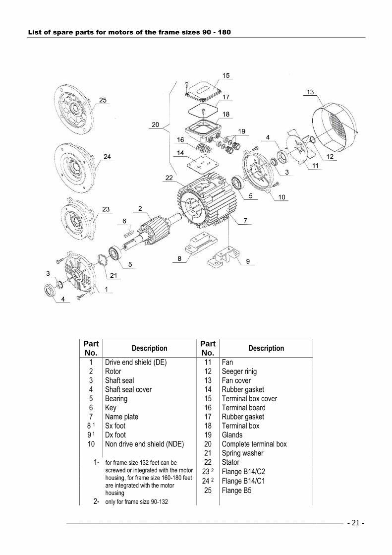
List of spare parts for motors of the frame sizes 90 - 180
Part No.
Description Part No.
Description
1 Drive end shield (DE) 11 Fan 2 Rotor 12 Seeger rinig 3 Shaft seal 13 Fan cover 4 Shaft seal cover 14 Rubber gasket 5 Bearing 15 Terminal box cover 6 Key 16 Terminal board 7 Name plate 17 Rubber gasket
8 1 Sx foot 18 Terminal box 9 1 Dx foot 19 Glands 10 Non drive end shield (NDE) 20 Complete terminal box 21 Spring washer 1- for frame size 132 feet can be
screwed or integrated with the motor housing, for frame size 160-180 feet are integrated with the motor housing
2- only for frame size 90-132
22 Stator
23 2 Flange B14/C2
24 2 Flange B14/C1
25 Flange B5

- 22 - ––––––––––––––––––––––––––––––––––––––––––––––––––––––––––––—–––––––––––––––————
List of spare parts for motors of the frame sizes 200 – 315 (except (2)SIE315)
Part No.
Description Part No.
Description
1 Drive end shield (DE) 16 Terminal board 2 Rotor 17 Rubber gasket 3 Shaft seal 18 Terminal box
4 1 Seeger ring 19 Rubber gasket
5 Bearing DE 20 Glands 6 Key 21 Complete terminal box 7 Stator with foot 22 Spring washer 8 Internal bearing cap 23 Seeger ring
9 External bearing cap 24 2 Grease shield
10 Non drive end shield (NDE) 25 2 Bearing internal ring
11 Fan 26 DE lubricator 12 Seeger ring 27 NDE lubricator 13 Fan cover 28 flange B5 14 Bearing NDE 1 only for frame size 200, 225 15 Terminal box cover 2 only for frame size 280-315

––––––––––––––––––––––––––––––––––––––––––––––––––––––––––––––––––––––––––––———— - 23 -
FFD COOLING MEDIUM PUMPS are used for pumping of cooling water or other coolants which are typically drilling-, cutting- and
shaving machines. These pumps are well known in the industry and have been built in all types of machine tools for many years.
FFD COOLING MEDIUM PUMPS work like centrifugal pumps, so the flow rate of the coolant is affected by pump parts, stuffing-box
and sucking up inlets. These pumps are quite resistant to the pollution of coolants.
FFD COOLING MEDIUM PUMPS are manufactured in with 5 different dip length. The dimensions of these pumps are according to
DIN 54440. By fully opened valve the pump has the maximum flow rate and the motor is fully loaded, when the valve is closed the load of the motor is lower. It´s not possible to overload the motor in these pumps.
FFD COOLING MEDIUM PUMPS have the advantage of an easy exchangeability of the stator. It´s not necessary to disassemble the
pump, it´s enough to come loose of only two screws to exchange the stator.
INSTALLATION At commisioning check the direction of rotation (it has to be the same like shown by the arrow on the frame). The max. level of the cooling medium should be a few cm below the flange and the min. level should flow in a 2inch pipe. The values in the tables below were attained for such a design. Safety valves are not necessary.
MOTOR Motors are manufactured acc. to VDE 0530/11.72 with insulation class E. The Insulation system is tropicalized. The winding for 230/400V is so designed that motors work properly within the range of voltage 220 – 250V and 380 – 440V both 50 Hz and 60 Hz. Single phase motors have built on the running capacitor on the frame.
COOLING MEDIUM PUMPS DKP and EKP Duty: S1 Degree of protection: IP54 Nominal voltage: 220–250/380–440V, 50/60Hz, 2800/3400rpm
Dip Flow rate in l/min Consumption
Type length at oil emulsion 3-5 E° of power
mm 0m 1m 2m 3m 4m W
DKP 1086 86
DKP 112 120
DKP 117 170 40 30 24 16 5,5 115
DKP 122 220
DKP 127 270
Nominal current IN = 0,42–0,57A at 220–250V, 50/60Hz IN = 0,24–0,32A at 380–440V, 50/60Hz
Single phase pumps 220–250V, 50/60Hz, 2800/3400rpm With running capacitor 4µF / 450V
EKP 1086 86
EKP 112 120
EKP 117 170 35 27 22 14 4 100
EKP 122 220
EKP 127 270
Nominal current IN = 0,6–0,8A at 220–250V, 50/60Hz Mounting dimensions
Type a b c e f g h k k1 o p n s X s2 T
DKP a. EKP 1086 169 25 118
M16 x1,5
86
DKP a. EKP 112
139 23 88
120
DKP a. EKP 117 130 100 8 115 98 98 75 85 72 6,5 R2― 170
DKP a. EKP 122 220
DKP a. EKP 127 270

- 24 - ––––––––––––––––––––––––––––––––––––––––––––––––––––––––––––—–––––––––––––––————
OTHER SPECIAL MOTORS AVAILABLE ON REQUEST
- High efficiency motors (IE2) - Explosion-proof motors acc. to ATEX - Submersible motors - Brake motors (with DC or AC brake) - Multiple-speed motors - Slip-ring motors for low and high voltage - Lift motors - Progressive motors (motors with increased output) - Motors to be built in
- Low and High voltage motors (up to 11 kV)
SPECIAL EXTRAS OF THE MOTORS
- Insulation class ―H‖ or ―C‖ - Windings thermal protection (PTC or Pt100) - Bearings thermal protection (PTC or Pt100) - Anti-condensation heater - External fan - Special shafts - Special flanges - Motors in special design acc. to the customer´s specification
FRANK & DVORAK Elektromaschinenbau- und Vertriebsgesellschaft m.b.H. u. Co.KG
CONTACT ADDRESS:
Industriestrasse 1 A-7033 Pöttsching (Burgenland),
Tel./Phone: +43 2631 / 8005 Telefax: +43 2631 / 8005 84 e-mail: [email protected] http://www.frank-dvorak.at
Edition 02/2012