ناهفصا يتعنص هاگشناد کیناکم هدکشناد · • in abaqus/cae a seam is...
TRANSCRIPT
دانشکده مکانیک -دانشگاه صنعتي اصفهان مکانیک شکست
دانشگاه صنعتي اصفهان دانشکده مکانیک
1
Modeling Fracture with Abaqus
دانشکده مکانیک -دانشگاه صنعتي اصفهان مکانیک شکست 2
Modeling Cracks
Calculation of Contour Integrals
Creating an XFEM Fracture Model
Modeling Fracture with Abaqus

دانشکده مکانیک -دانشگاه صنعتي اصفهان مکانیک شکست 3
Crack Modeling Overview
•A crack can be modeled as either
•Sharp
•Small-strain analysis
•Singular behavior at the crack tip
•Requires special attention
•In Abaqus, a sharp crack is
modeled using seam geometry
•Blunted
•Finite-strain analysis
•Non-singular behavior at crack tip
•In Abaqus, a blunted crack is
modeled using open geometry
•For example, a notch

دانشکده مکانیک -دانشگاه صنعتي اصفهان مکانیک شکست 4
Crack Modeling Overview
•The crack-tip singularity in small-strain analysis
• For mesh convergence in a small-strain analysis, the singularity at the
crack tip must be considered.
• J values are more accurate if some singularity is included in the
mesh at the crack tip than if no singularity is included.
• The stress and strain fields local to the crack tip will be modeled
more accurately if singularities are considered.
•In small-strain analysis, the strain singularity is:
•Linear elasticity
•Perfect plasticity
•Power-law hardening
1
r
1
r
1
1
n
nr

دانشکده مکانیک -دانشگاه صنعتي اصفهان مکانیک شکست 5
Modeling Sharp Cracks in Two Dimensions
In two dimensions…
•The crack is modeled as an internal edge partition
embedded (partially or wholly) inside a face.
•This is called a seam crack
•The edge along the seam will have duplicate
nodes such that the elements on the opposite
sides of the edge will not share nodes.
•Typically, the entire 2D part is filled with a quad
or quad-dominated mesh.
•At the crack tip, a ring of triangles are
inserted along with concentric layers of
structured quads.
•All triangles in the contour domains must be
represented as degenerated quads.
دانشکده مکانیک -دانشگاه صنعتي اصفهان مکانیک شکست 6
Modeling Sharp Cracks in Two Dimensions
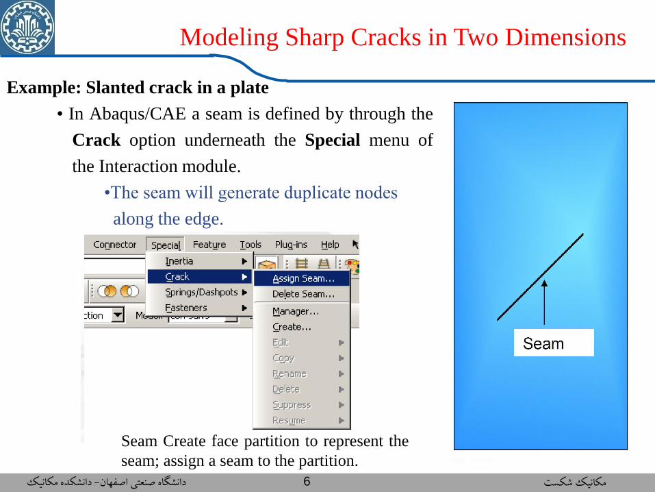
Example: Slanted crack in a plate
• In Abaqus/CAE a seam is defined by through the
Crack option underneath the Special menu of
the Interaction module.
•The seam will generate duplicate nodes
along the edge.
Seam Create face partition to represent the
seam; assign a seam to the partition.
دانشکده مکانیک -دانشگاه صنعتي اصفهان مکانیک شکست 7
Modeling Sharp Cracks in Two Dimensions
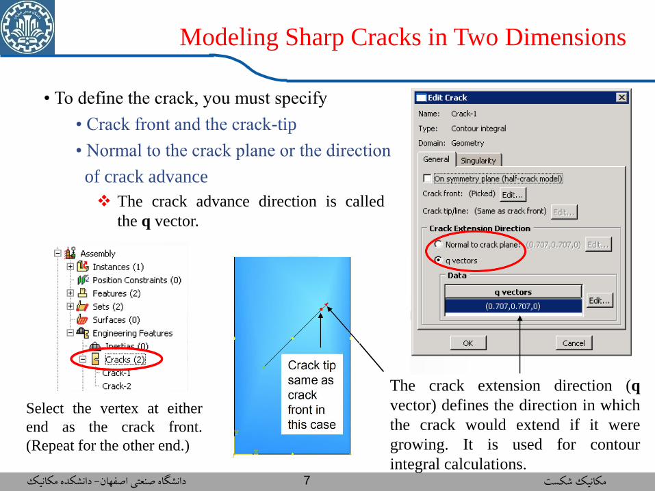
• To define the crack, you must specify
• Crack front and the crack-tip
• Normal to the crack plane or the direction
of crack advance
The crack advance direction is called
the q vector.
The crack extension direction (q
vector) defines the direction in which
the crack would extend if it were
growing. It is used for contour
integral calculations.
Select the vertex at either
end as the crack front.
(Repeat for the other end.)

دانشکده مکانیک -دانشگاه صنعتي اصفهان مکانیک شکست 8
Modeling Sharp Cracks in Two Dimensions
• Other options for defining the crack front and crack tip
دانشکده مکانیک -دانشگاه صنعتي اصفهان مکانیک شکست 9
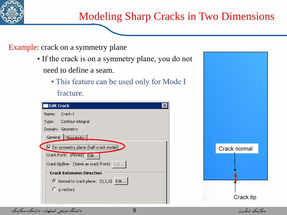
Modeling Sharp Cracks in Two Dimensions
Example: crack on a symmetry plane
• If the crack is on a symmetry plane, you do not
need to define a seam.
• This feature can be used only for Mode I
fracture.
دانشکده مکانیک -دانشگاه صنعتي اصفهان مکانیک شکست 10
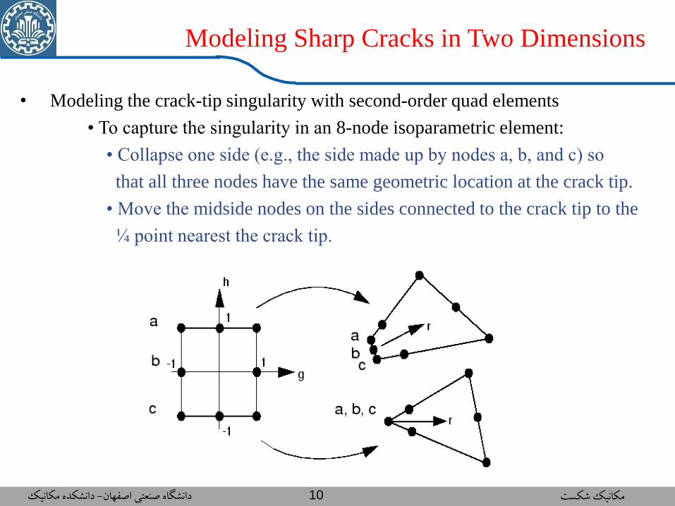
Modeling Sharp Cracks in Two Dimensions
• Modeling the crack-tip singularity with second-order quad elements
• To capture the singularity in an 8-node isoparametric element:
• Collapse one side (e.g., the side made up by nodes a, b, and c) so
that all three nodes have the same geometric location at the crack tip.
• Move the midside nodes on the sides connected to the crack tip to the
¼ point nearest the crack tip.
دانشکده مکانیک -دانشگاه صنعتي اصفهان مکانیک شکست 11
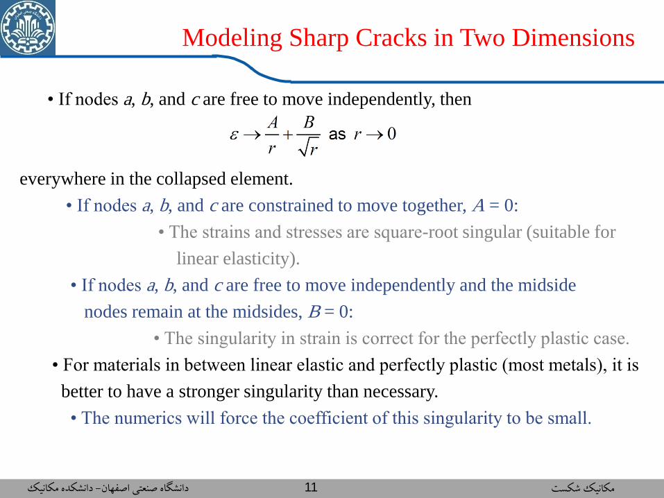
Modeling Sharp Cracks in Two Dimensions
• If nodes a, b, and c are free to move independently, then
everywhere in the collapsed element.
• If nodes a, b, and c are constrained to move together, A = 0:
• The strains and stresses are square-root singular (suitable for
linear elasticity).
• If nodes a, b, and c are free to move independently and the midside
nodes remain at the midsides, B = 0:
• The singularity in strain is correct for the perfectly plastic case.
• For materials in between linear elastic and perfectly plastic (most metals), it is
better to have a stronger singularity than necessary.
• The numerics will force the coefficient of this singularity to be small.

دانشکده مکانیک -دانشگاه صنعتي اصفهان مکانیک شکست 12
Modeling Sharp Cracks in Two Dimensions
• Usage:
Quarter-point midside nodes
on the sides connected to
the crack tip
The crack tip nodes are
constrained: r -½ singularity
The crack tip nodes are
independent: r -1 singularity
دانشکده مکانیک -دانشگاه صنعتي اصفهان مکانیک شکست 13
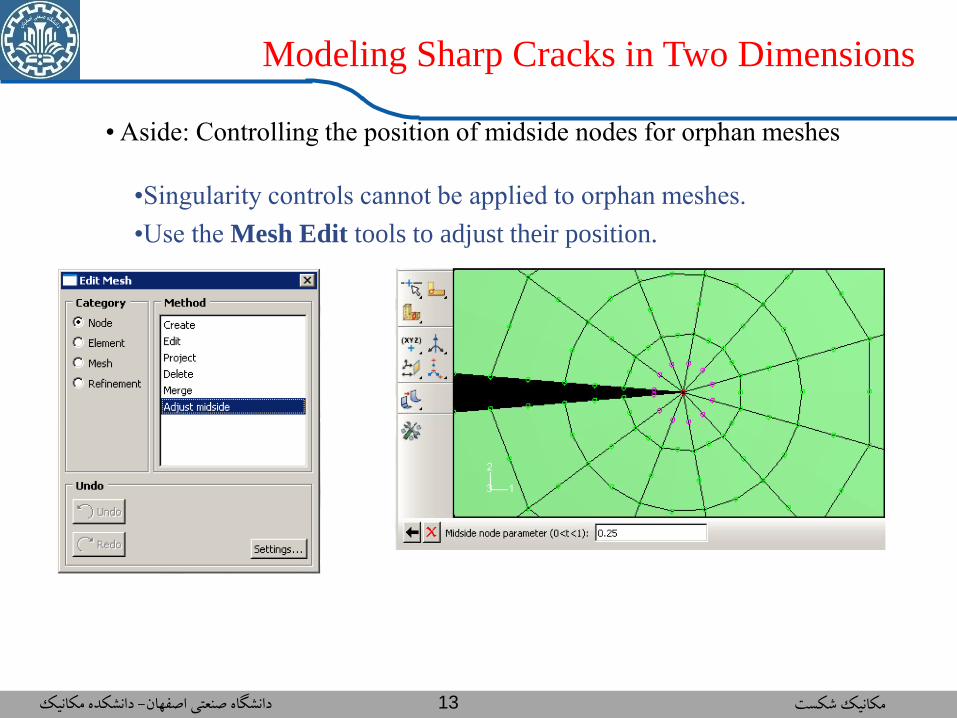
Modeling Sharp Cracks in Two Dimensions
• Aside: Controlling the position of midside nodes for orphan meshes
•Singularity controls cannot be applied to orphan meshes.
•Use the Mesh Edit tools to adjust their position.
دانشکده مکانیک -دانشگاه صنعتي اصفهان مکانیک شکست 14
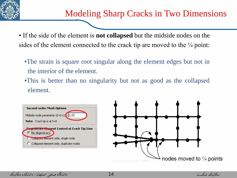
Modeling Sharp Cracks in Two Dimensions
• If the side of the element is not collapsed but the midside nodes on the
sides of the element connected to the crack tip are moved to the ¼ point:
•The strain is square root singular along the element edges but not in
the interior of the element.
•This is better than no singularity but not as good as the collapsed
element.
دانشکده مکانیک -دانشگاه صنعتي اصفهان مکانیک شکست 15
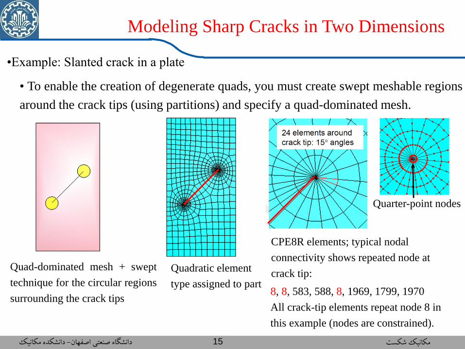
Modeling Sharp Cracks in Two Dimensions
•Example: Slanted crack in a plate
Quad-dominated mesh + swept
technique for the circular regions
surrounding the crack tips
• To enable the creation of degenerate quads, you must create swept meshable regions
around the crack tips (using partitions) and specify a quad-dominated mesh.
Quadratic element
type assigned to part
CPE8R elements; typical nodal
connectivity shows repeated node at
crack tip:
8, 8, 583, 588, 8, 1969, 1799, 1970
All crack-tip elements repeat node 8 in
this example (nodes are constrained).
Quarter-point nodes

دانشکده مکانیک -دانشگاه صنعتي اصفهان مکانیک شکست 16
Modeling Sharp Cracks in Two Dimensions
•Example: Slanted crack in a
plate; Alternate meshes
CPE8R elements at crack tip but no repeated
nodes:1993, 1992, 583, 588, 2016, ...
Coincident nodes
located at crack tip
With swept meshable region:
CPE6M elements at crack tip-
cannot be used for fracture
studies in Abaqus.
• No degeneracy:
• Degenerate with
duplicate nodes:
With arbitrary mesh,
singularity only along edges
connected to crack tip.

دانشکده مکانیک -دانشگاه صنعتي اصفهان مکانیک شکست 17
Modeling Sharp Cracks in Two Dimensions
•Example: Slanted crack in plate; Deformed shape
• Focused mesh • Arbitrary mesh
دانشکده مکانیک -دانشگاه صنعتي اصفهان مکانیک شکست 18
Contour 3
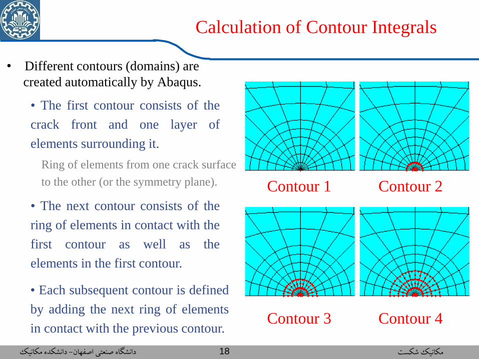
Calculation of Contour Integrals
• Different contours (domains) are
created automatically by Abaqus.
• The first contour consists of the
crack front and one layer of
elements surrounding it.
Ring of elements from one crack surface
to the other (or the symmetry plane).
• The next contour consists of the
ring of elements in contact with the
first contour as well as the
elements in the first contour.
• Each subsequent contour is defined
by adding the next ring of elements
in contact with the previous contour. Contour 4
Contour 1 Contour 2

دانشکده مکانیک -دانشگاه صنعتي اصفهان مکانیک شکست 19
Calculation of Contour Integrals
• The J-integral and the Ct-integral at steady-state creep should be path
(domain) independent.
• The value for the first contour is generally ignored.
• Each subsequent contour is defined
by adding the next ring of elements
in contact with the previous contour.
• Examples of contour domains:
دانشکده مکانیک -دانشگاه صنعتي اصفهان مکانیک شکست 20
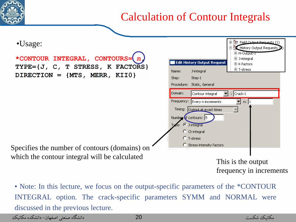
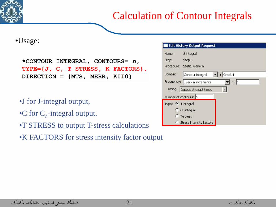
Calculation of Contour Integrals
•Usage:
• Note: In this lecture, we focus on the output-specific parameters of the *CONTOUR
INTEGRAL option. The crack-specific parameters SYMM and NORMAL were
discussed in the previous lecture.
Specifies the number of contours (domains) on
which the contour integral will be calculated This is the output
frequency in increments
دانشکده مکانیک -دانشگاه صنعتي اصفهان مکانیک شکست 21
Calculation of Contour Integrals
•Usage:
•J for J-integral output,
•C for Ct -integral output.
•T STRESS to output T-stress calculations
•K FACTORS for stress intensity factor output
دانشکده مکانیک -دانشگاه صنعتي اصفهان مکانیک شکست 22
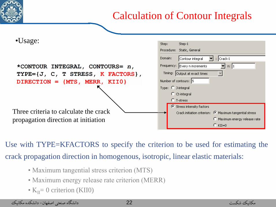
Calculation of Contour Integrals
•Usage:
Use with TYPE=KFACTORS to specify the criterion to be used for estimating the
crack propagation direction in homogenous, isotropic, linear elastic materials:
Three criteria to calculate the crack
propagation direction at initiation
• Maximum tangential stress criterion (MTS)
• Maximum energy release rate criterion (MERR)
• KII= 0 criterion (KII0)

دانشکده مکانیک -دانشگاه صنعتي اصفهان مکانیک شکست 23
Calculation of Contour Integrals
• Loads
• Thermal loads.
• Crack-face pressure and traction loads on continuum elements as well as
those applied using user subroutines DLOADand UTRACLOAD.
•Surface traction and crack-face edge loads on shell elements as well as
those applied using user subroutine UTRACLOAD.
•Uniform and nonuniform body forces.
•Centrifugal loads on continuum and shell elements.
• Loads included in contour integral calculations:
• Not all types of distributed loads (e.g., hydrostatic pressure and gravity
loads) are included in the contour integral calculations.
• The presence of these loads will result in a warning message.
دانشکده مکانیک -دانشگاه صنعتي اصفهان مکانیک شکست 24
Calculation of Contour Integrals
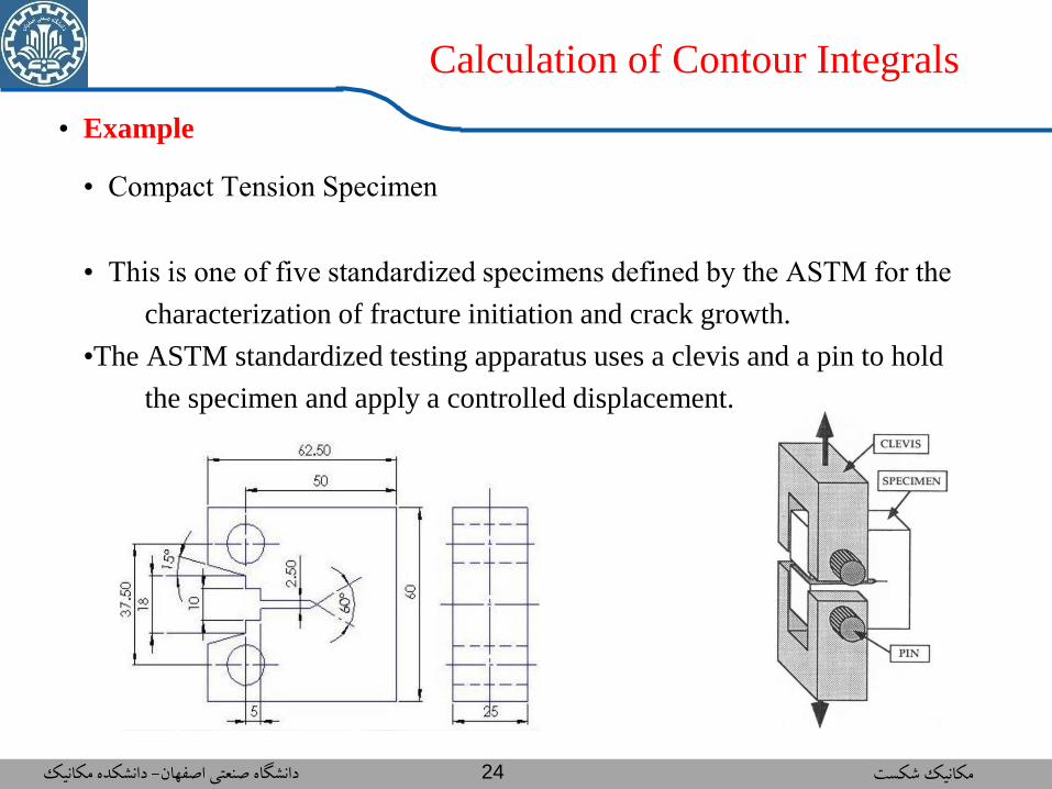
• Example
• Compact Tension Specimen
• This is one of five standardized specimens defined by the ASTM for the
characterization of fracture initiation and crack growth.
•The ASTM standardized testing apparatus uses a clevis and a pin to hold
the specimen and apply a controlled displacement.
دانشکده مکانیک -دانشگاه صنعتي اصفهان مکانیک شکست 25
Calculation of Contour Integrals
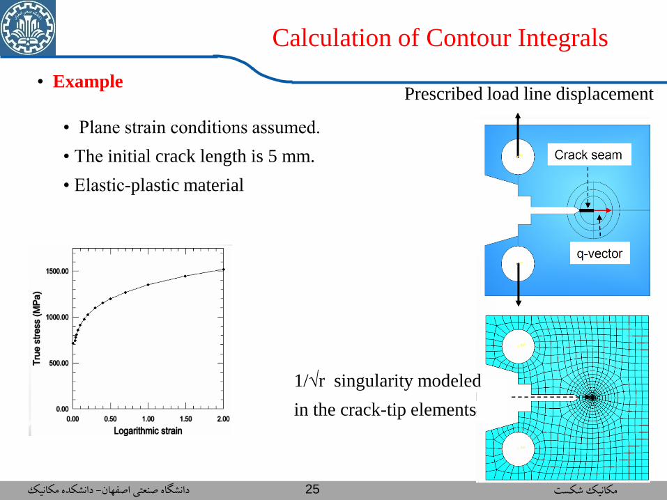
• Example
• Plane strain conditions assumed.
• The initial crack length is 5 mm.
• Elastic-plastic material
1/√r singularity modeled
in the crack-tip elements
Prescribed load line displacement

دانشکده مکانیک -دانشگاه صنعتي اصفهان مکانیک شکست 26
Calculation of Contour Integrals
• Results
• Small strain analysis • Finite strain analysis

دانشکده مکانیک -دانشگاه صنعتي اصفهان مکانیک شکست 27
Calculation of Contour Integrals
• Results
• At small to moderate strain
levels, the small and finite
strain models yield similar
results.
• Finite strain effects must be
considered to represent this
level of deformation and
strain accurately.
دانشکده مکانیک -دانشگاه صنعتي اصفهان مکانیک شکست 28
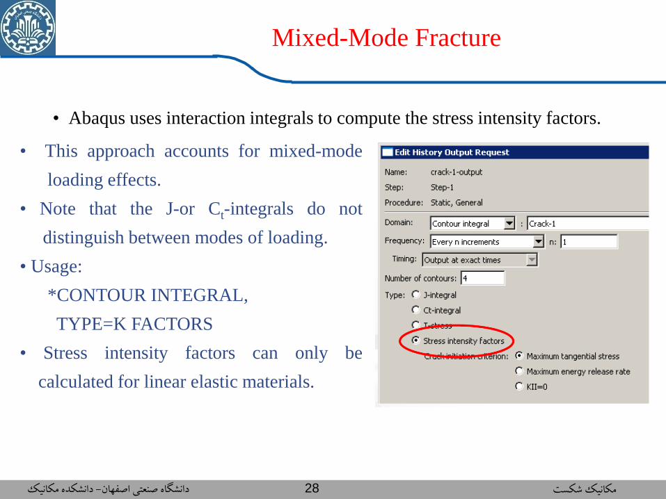
Mixed-Mode Fracture
• This approach accounts for mixed-mode
loading effects.
• Note that the J-or Ct-integrals do not
distinguish between modes of loading.
• Usage:
*CONTOUR INTEGRAL,
TYPE=K FACTORS
• Stress intensity factors can only be
calculated for linear elastic materials.
• Abaqus uses interaction integrals to compute the stress intensity factors.
دانشکده مکانیک -دانشگاه صنعتي اصفهان مکانیک شکست 29
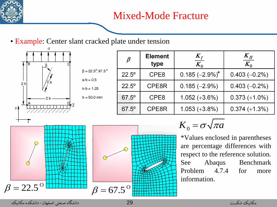
Mixed-Mode Fracture
• Example: Center slant cracked plate under tension
*Values enclosed in parentheses
are percentage differences with
respect to the reference solution.
See Abaqus Benchmark
Problem 4.7.4 for more
information. O67.5
O22.5
0K a