0137033451 pp4
TRANSCRIPT

Copyright ©2011, 2006 by Pearson Education, Inc.publishing as Pearson [imprint]
Construction Methods and Management, 8th ed.S. W. Nunnally
Chapter 4
LOADING AND HAULING

Copyright ©2011, 2006 by Pearson Education, Inc.publishing as Pearson [imprint]
Construction Methods and Management, 8th ed.S. W. Nunnally
ESTIMATING EQUIPMENT TRAVEL TIME
• In calculating the time required for a haul unit to make one complete cycle, it is customary to break the cycle down into fixed and variable components.– Cycle time = Fixed time + Variable time
• Fixed time represents those components of cycle time other than travel time.
• Variable time represents the travel time required for a unit to haul material to the unloading site and return.

Copyright ©2011, 2006 by Pearson Education, Inc.publishing as Pearson [imprint]
Construction Methods and Management, 8th ed.S. W. Nunnally
ESTIMATING EQUIPMENT TRAVEL TIME
• Rolling Resistance– To determine the maximum speed of a
vehicle in a specific situation, it is necessary to determine the total resistance to movement of the vehicle.
– The resistance that a vehicle encounters in traveling over a surface is made up of two components, rolling resistance and grade resistance.
• Total resistance = Grade resistance + Rolling resistance

Copyright ©2011, 2006 by Pearson Education, Inc.publishing as Pearson [imprint]
Construction Methods and Management, 8th ed.S. W. Nunnally
ESTIMATING EQUIPMENT TRAVEL TIME
Table 4-1. Typical values of rolling resistance factor

Copyright ©2011, 2006 by Pearson Education, Inc.publishing as Pearson [imprint]
Construction Methods and Management, 8th ed.S. W. Nunnally
ESTIMATING EQUIPMENT TRAVEL TIME
• Grade Resistance– Grade resistance represents that
component of vehicle weight which acts parallel to an inclined surface.
• When the vehicle is traveling up a grade, grade resistance is positive.
• When traveling downhill, grade resistance is negative.
Copyright ©2011, 2006 by Pearson Education, Inc.publishing as Pearson [imprint]
Construction Methods and Management, 8th ed.S. W. Nunnally
ESTIMATING EQUIPMENT TRAVEL TIME
• Effective Grade– The total resistance to movement of a vehicle (the
sum of its rolling resistance and grade resistance) may be expressed in pounds or kilograms.
– However, a somewhat simpler method for expressing total resistance is to state it as a grade (%), which would have a grade resistance equivalent to the total resistance actually encountered.
– This method of expressing total resistance is referred to as effective grade, equivalent grade, or percent total resistance and is often used in manufacturers’ performance charts.

Copyright ©2011, 2006 by Pearson Education, Inc.publishing as Pearson [imprint]
Construction Methods and Management, 8th ed.S. W. Nunnally
ESTIMATING EQUIPMENT TRAVEL TIME
• Effect of Altitude– All internal combustion engines lose power
as their elevation above sea level increases because of the decreased density of air at higher elevations.
• Effect of Traction– The power available to move a vehicle and
its load is expressed as rimpull for wheel vehicles and drawbar pull for crawler tractors.

Copyright ©2011, 2006 by Pearson Education, Inc.publishing as Pearson [imprint]
Construction Methods and Management, 8th ed.S. W. Nunnally
ESTIMATING EQUIPMENT TRAVEL TIME
Table 4-2. Typical values of coefficient of traction

Copyright ©2011, 2006 by Pearson Education, Inc.publishing as Pearson [imprint]
Construction Methods and Management, 8th ed.S. W. Nunnally
ESTIMATING EQUIPMENT TRAVEL TIME
• Use of Performance and Retarder Curves
FIGURE 4-1. Typical crawler tractor performance curve.

Copyright ©2011, 2006 by Pearson Education, Inc.publishing as Pearson [imprint]
Construction Methods and Management, 8th ed.S. W. Nunnally
ESTIMATING EQUIPMENT TRAVEL TIME
FIGURE 4-2. Wheel scraper performance curve. (Reprinted Courtesy of Caterpillar Inc.)

Copyright ©2011, 2006 by Pearson Education, Inc.publishing as Pearson [imprint]
Construction Methods and Management, 8th ed.S. W. Nunnally
ESTIMATING EQUIPMENT TRAVEL TIME
FIGURE 4-3. Wheel scraper retarder curve. (Reprinted Courtesy of Caterpillar Inc.)

Copyright ©2011, 2006 by Pearson Education, Inc.publishing as Pearson [imprint]
Construction Methods and Management, 8th ed.S. W. Nunnally
ESTIMATING EQUIPMENT TRAVEL TIME
• Estimating Travel Time
Table 4-3. Average speed factors

Copyright ©2011, 2006 by Pearson Education, Inc.publishing as Pearson [imprint]
Construction Methods and Management, 8th ed.S. W. Nunnally
ESTIMATING EQUIPMENT TRAVEL TIME
FIGURE 4-4. Scraper travel time—loaded. (Reprinted Courtesy of Caterpillar Inc.)

Copyright ©2011, 2006 by Pearson Education, Inc.publishing as Pearson [imprint]
Construction Methods and Management, 8th ed.S. W. Nunnally
ESTIMATING EQUIPMENT TRAVEL TIME
FIGURE 4-5. Scraper travel time—empty. (Reprinted Courtesy of Caterpillar Inc.)
Copyright ©2011, 2006 by Pearson Education, Inc.publishing as Pearson [imprint]
Construction Methods and Management, 8th ed.S. W. Nunnally
DOZERS
• Tractors and Dozers– A tractor equipped with a front-mounted
earthmoving blade is known as a dozer or bulldozer.
– A dozer moves earth by lowering the blade and cutting until a full blade load of material is obtained.
– It then pushes the material across the ground surface to the required location.

Copyright ©2011, 2006 by Pearson Education, Inc.publishing as Pearson [imprint]
Construction Methods and Management, 8th ed.S. W. Nunnally
DOZERS
FIGURE 4-6. Crawler tractor dozer. (Courtesy of New Holland Construction)

Copyright ©2011, 2006 by Pearson Education, Inc.publishing as Pearson [imprint]
Construction Methods and Management, 8th ed.S. W. Nunnally
DOZERS
FIGURE 4-7. High-speed crawler dozer. (Courtesy of John Deere Construction & Forestry Company)

Copyright ©2011, 2006 by Pearson Education, Inc.publishing as Pearson [imprint]
Construction Methods and Management, 8th ed.S. W. Nunnally
DOZERS
• Dozer Blades
FIGURE 4-8. Common types of dozer blades.

Copyright ©2011, 2006 by Pearson Education, Inc.publishing as Pearson [imprint]
Construction Methods and Management, 8th ed.S. W. Nunnally
DOZERS
FIGURE 4-9. Dozer blade adjustment.

Copyright ©2011, 2006 by Pearson Education, Inc.publishing as Pearson [imprint]
Construction Methods and Management, 8th ed.S. W. Nunnally
DOZERS
• Estimating Dozer Production
Table 4-4. Typical dozer fixed cycle times

Copyright ©2011, 2006 by Pearson Education, Inc.publishing as Pearson [imprint]
Construction Methods and Management, 8th ed.S. W. Nunnally
DOZERS
Table 4-5. Typical dozer operating speeds

Copyright ©2011, 2006 by Pearson Education, Inc.publishing as Pearson [imprint]
Construction Methods and Management, 8th ed.S. W. Nunnally
LOADERS
• A tractor equipped with a front-end bucket is called a loader, front-end loader, or bucket loader.
FIGURE 4-10. Articulated wheel loader with articulated hauler. (Courtesy of Volvo Construction Equipment North America, Inc.)
Copyright ©2011, 2006 by Pearson Education, Inc.publishing as Pearson [imprint]
Construction Methods and Management, 8th ed.S. W. Nunnally
LOADERS
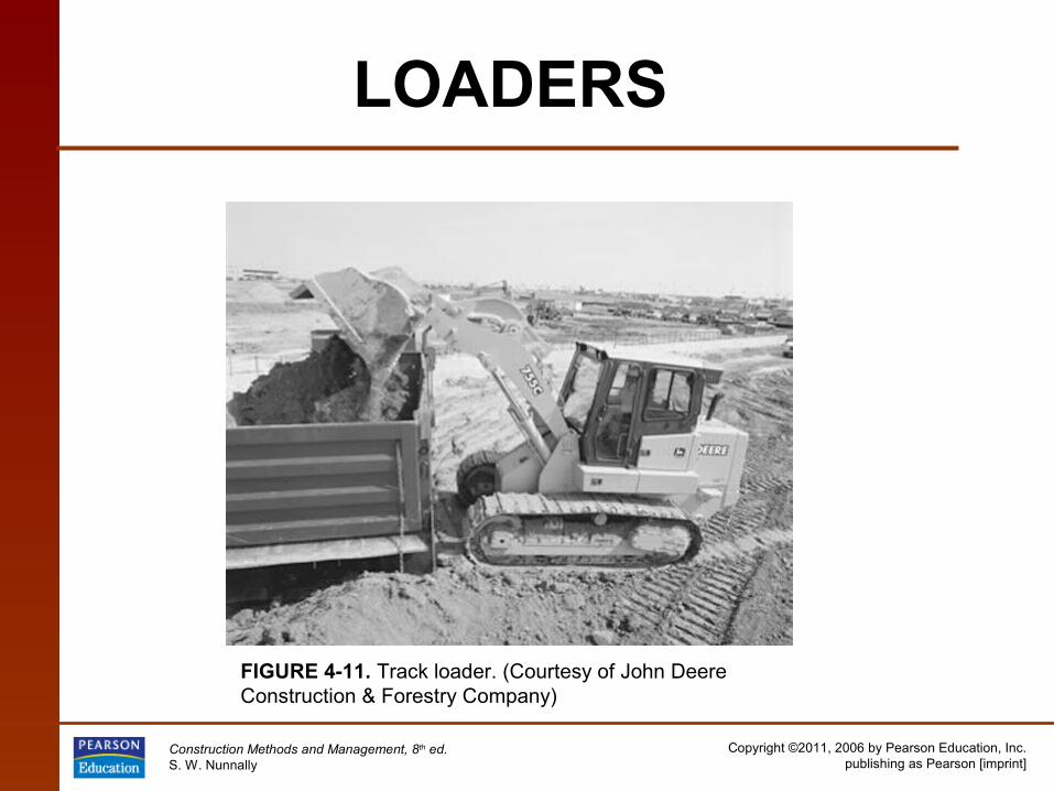
FIGURE 4-11. Track loader. (Courtesy of John Deere Construction & Forestry Company)

Copyright ©2011, 2006 by Pearson Education, Inc.publishing as Pearson [imprint]
Construction Methods and Management, 8th ed.S. W. Nunnally
LOADERS
FIGURE 4-12. Backhoe loader. (Courtesy of JCB Inc.)

Copyright ©2011, 2006 by Pearson Education, Inc.publishing as Pearson [imprint]
Construction Methods and Management, 8th ed.S. W. Nunnally
LOADERS
• Tool Carriers
• Skid-Steer Loaders
• Material Handlers
• Estimating Loader Production
• Job Management

Copyright ©2011, 2006 by Pearson Education, Inc.publishing as Pearson [imprint]
Construction Methods and Management, 8th ed.S. W. Nunnally
LOADERS
FIGURE 4-13. Skid-steer loader with backhoe attachment. (Courtesy of the Bobcat Company) FIGURE 4-14. Compact track loader.
(Courtesy of the Bobcat Company)

Copyright ©2011, 2006 by Pearson Education, Inc.publishing as Pearson [imprint]
Construction Methods and Management, 8th ed.S. W. Nunnally
LOADERS
FIGURE 4-15. Material handler. (Courtesy of JLG Industries, Inc.)

Copyright ©2011, 2006 by Pearson Education, Inc.publishing as Pearson [imprint]
Construction Methods and Management, 8th ed.S. W. Nunnally
LOADERS
Table 4-6. Basic loader cycle time

Copyright ©2011, 2006 by Pearson Education, Inc.publishing as Pearson [imprint]
Construction Methods and Management, 8th ed.S. W. Nunnally
LOADERS
FIGURE 4-16. Travel time, wheel loader (haul + return).

Copyright ©2011, 2006 by Pearson Education, Inc.publishing as Pearson [imprint]
Construction Methods and Management, 8th ed.S. W. Nunnally
LOADERS
FIGURE 4-17. Multisegment loader bucket.

Copyright ©2011, 2006 by Pearson Education, Inc.publishing as Pearson [imprint]
Construction Methods and Management, 8th ed.S. W. Nunnally
SCRAPERS
• Operation and Employment– Scrapers are capable of excavating, hauling, and
dumping material over medium- to long-haul distances.
– The scraper excavates (or cuts) by lowering the front edge of its bowl into the soil.
– The bowl front edge is equipped with replaceable cutting blades, which may be straight, curved, or extended at the center (stinger arrangement).

Copyright ©2011, 2006 by Pearson Education, Inc.publishing as Pearson [imprint]
Construction Methods and Management, 8th ed.S. W. Nunnally
SCRAPERS
FIGURE 4-18. Twin-engine all-wheel drive scraper. (Reprinted Courtesy of Caterpillar Inc.)

Copyright ©2011, 2006 by Pearson Education, Inc.publishing as Pearson [imprint]
Construction Methods and Management, 8th ed.S. W. Nunnally
SCRAPERS
FIGURE 4-19. Elevating scraper. (Reprinted Courtesy of Caterpillar Inc.)

Copyright ©2011, 2006 by Pearson Education, Inc.publishing as Pearson [imprint]
Construction Methods and Management, 8th ed.S. W. Nunnally
SCRAPERS
FIGURE 4-20. Twin-hitch scraper loading. (Courtesy of CMI Terex Corporation)

Copyright ©2011, 2006 by Pearson Education, Inc.publishing as Pearson [imprint]
Construction Methods and Management, 8th ed.S. W. Nunnally
SCRAPERS
FIGURE 4-21. Pull scraper. (Courtesy of John Deere & Company)
FIGURE 4-22. Tandem pull-scrapers. (Courtesy of John Deere & Company)

Copyright ©2011, 2006 by Pearson Education, Inc.publishing as Pearson [imprint]
Construction Methods and Management, 8th ed.S. W. Nunnally
SCRAPERS
• Estimating Scraper Production
Table 4-7. Scraper fixed time (min)

Copyright ©2011, 2006 by Pearson Education, Inc.publishing as Pearson [imprint]
Construction Methods and Management, 8th ed.S. W. Nunnally
SCRAPERS
• Push-Loading
FIGURE 4-23. Methods of push-loading scrapers.

Copyright ©2011, 2006 by Pearson Education, Inc.publishing as Pearson [imprint]
Construction Methods and Management, 8th ed.S. W. Nunnally
SCRAPERS
• Optimum Load Time
FIGURE 4-24. A load growth curve.

Copyright ©2011, 2006 by Pearson Education, Inc.publishing as Pearson [imprint]
Construction Methods and Management, 8th ed.S. W. Nunnally
SCRAPERS
FIGURE 4-25. Finding the optimum load time.

Copyright ©2011, 2006 by Pearson Education, Inc.publishing as Pearson [imprint]
Construction Methods and Management, 8th ed.S. W. Nunnally
SCRAPERS
• Calculating the Number of Pushers Required
Table 4-8. Typical pusher cycle time (min)

Copyright ©2011, 2006 by Pearson Education, Inc.publishing as Pearson [imprint]
Construction Methods and Management, 8th ed.S. W. Nunnally
SCRAPERS
• Push-Pull Loading• Job Management
FIGURE 4-26. Scraper application zones.
Copyright ©2011, 2006 by Pearson Education, Inc.publishing as Pearson [imprint]
Construction Methods and Management, 8th ed.S. W. Nunnally
TRUCKS AND WAGONS
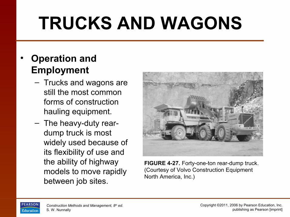
• Operation and Employment– Trucks and wagons are
still the most common forms of construction hauling equipment.
– The heavy-duty rear-dump truck is most widely used because of its flexibility of use and the ability of highway models to move rapidly between job sites.
FIGURE 4-27. Forty-one-ton rear-dump truck. (Courtesy of Volvo Construction Equipment North America, Inc.)

Copyright ©2011, 2006 by Pearson Education, Inc.publishing as Pearson [imprint]
Construction Methods and Management, 8th ed.S. W. Nunnally
TRUCKS AND WAGONS
FIGURE 4-28. All-wheel-drive articulated dump truck. (Courtesy of CMI Terex Corporation)

Copyright ©2011, 2006 by Pearson Education, Inc.publishing as Pearson [imprint]
Construction Methods and Management, 8th ed.S. W. Nunnally
TRUCKS AND WAGONS
FIGURE 4-29. Bottom-dump wagon. (Courtesy of CMI Terex Corporation)

Copyright ©2011, 2006 by Pearson Education, Inc.publishing as Pearson [imprint]
Construction Methods and Management, 8th ed.S. W. Nunnally
TRUCKS AND WAGONS
• Determining the Number of Haul Units Needed
• Job Management
Table 4-9. Spot, maneuver, and dump time for trucks and wagons (min)