12 tig welding
TRANSCRIPT
8/13/2019 12 Tig Welding
http://slidepdf.com/reader/full/12-tig-welding 1/8
Rev 1 January 2010TIG Welding
Copyright© TWI Ltd 2010
1 Process Characteristics
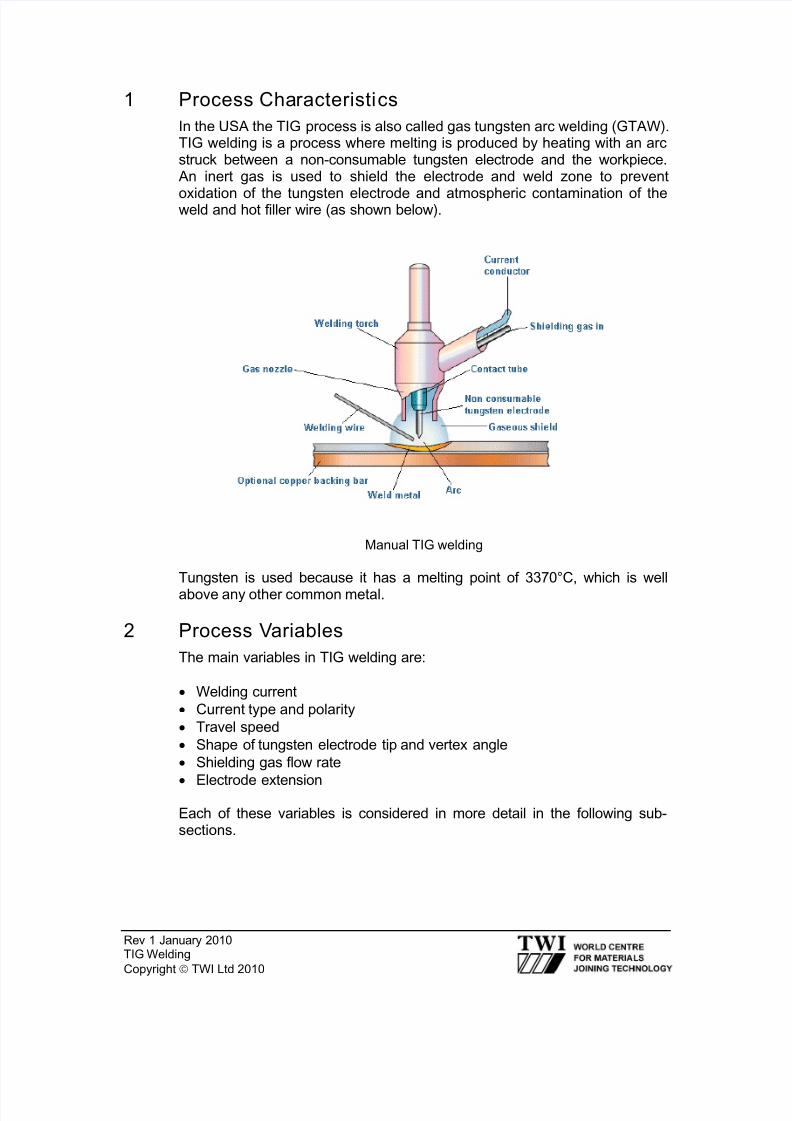
In the USA the TIG process is also called gas tungsten arc welding (GTAW).TIG welding is a process where melting is produced by heating with an arcstruck between a non-consumable tungsten electrode and the workpiece. An inert gas is used to shield the electrode and weld zone to prevent
oxidation of the tungsten electrode and atmospheric contamination of theweld and hot filler wire (as shown below).
Manual TIG welding
Tungsten is used because it has a melting point of 3370°C, which is well
above any other common metal.
2 Process Variables
The main variables in TIG welding are:
• Welding current
• Current type and polarity
• Travel speed
• Shape of tungsten electrode tip and vertex angle
• Shielding gas flow rate
• Electrode extension
Each of these variables is considered in more detail in the following sub-sections.
8/13/2019 12 Tig Welding
http://slidepdf.com/reader/full/12-tig-welding 2/8
Rev 1 January 2010TIG Welding
Copyright© TWI Ltd 2010
2.1 Welding current
• Weld penetration is directly related to welding current
• If the welding current is too low, the electrode tip will not be properlyheated and an unstable arc may result
• If the welding current is too high, the electrode tip might overheat and
melt, leading to tungsten inclusions
2.2 Current type and polarity
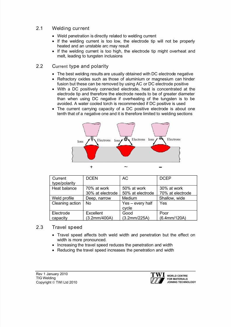
• The best welding results are usually obtained with DC electrode negative
• Refractory oxides such as those of aluminium or magnesium can hinderfusion but these can be removed by using AC or DC electrode positive
• With a DC positively connected electrode, heat is concentrated at theelectrode tip and therefore the electrode needs to be of greater diameterthan when using DC negative if overheating of the tungsten is to beavoided. A water cooled torch is recommended if DC positive is used
• The current carrying capacity of a DC positive electrode is about one
tenth that of a negative one and it is therefore limited to welding sections
IonsElectrons Ions Electrons Ions Electrons
2.3 Travel speed• Travel speed affects both weld width and penetration but the effect on
width is more pronounced.
• Increasing the travel speed reduces the penetration and width
• Reducing the travel speed increases the penetration and width
Currenttype/polarity
DCEN AC DCEP
Heat balance 70% at work30% at electrode
50% at work50% at electrode
30% at work70% at electrode
Weld profile Deep, narrow Medium Shallow, wide
Cleaning action No Yes – every halfcycle
Yes
Electrodecapacity
Excellent(3.2mm/400A)
Good(3.2mm/225A)
Poor(6.4mm/120A)
8/13/2019 12 Tig Welding
http://slidepdf.com/reader/full/12-tig-welding 3/8
Rev 1 January 2010TIG Welding
Copyright© TWI Ltd 2010
2.4 Tungsten electrode types
Different types of tungsten electrodes can be used to suit differentapplications:
• Pure tungsten electrodes are used when welding light metals with AC
because of their ability to maintain a clean balled end. However theypossess poor arc initiation and stability in AC mode compared with othertypes
• Thoriated electrodes are alloyed with thorium oxide (thoria) to improvearc initiation. They have higher current carrying capacity than puretungsten electrodes and maintain a sharp tip for longer. Unfortunately,
thoria is slightly radioactive (emitting α radiation) and the dust generatedduring tip grinding should not be inhaled. Electrode grinding machinesused for thoriated tungsten grinding should be fitted with a dust extractionsystem.
• Ceriated and lanthaniated electrodes are alloyed with cerium andlanthanum oxides, for the same reason as thoriated electrodes. They
operate successfully with DC or AC but since cerium and lanthanum arenot radioactive, these types have been used as replacements forthoriated electrodes
• Zirconiated electrodes are alloyed with zirconium oxide. Operatingcharacteristics of these electrodes fall between the thoriated types andpure tungsten. However, since they are able to retain a balled end duringwelding, they are recommended for AC welding. Also, they have a highresistance to contamination and so are used for high integrity weldswhere tungsten inclusions must be avoided.
2.5 Shape of tungsten electrode tip
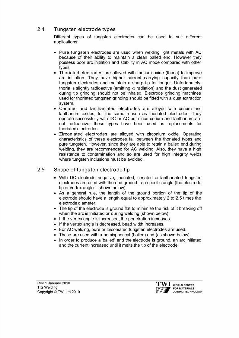
• With DC electrode negative, thoriated, ceriated or lanthanated tungstenelectrodes are used with the end ground to a specific angle (the electrodetip or vertex angle – shown below).
• As a general rule, the length of the ground portion of the tip of theelectrode should have a length equal to approximately 2 to 2.5 times theelectrode diameter.
• The tip of the electrode is ground flat to minimise the risk of it breaking offwhen the arc is initiated or during welding (shown below).
• If the vertex angle is increased, the penetration increases.
• If the vertex angle is decreased, bead width increases.
• For AC welding, pure or zirconiated tungsten electrodes are used.
•
These are used with a hemispherical (balled) end (as shown below).• In order to produce a ‘balled’ end the electrode is ground, an arc initiatedand the current increased until it melts the tip of the electrode.
8/13/2019 12 Tig Welding
http://slidepdf.com/reader/full/12-tig-welding 4/8
Rev 1 January 2010TIG Welding
Copyright© TWI Ltd 2010
2.6 Shielding gases
The following inert gases can be used as shielding gases for TIG welding:
• Argon
• Helium
• Mixtures of argon and helium
Note: For austenitic stainless steels and some cupro-nickel alloys, argonwith up to ~5% hydrogen may be used to improve penetration and reduceporosity
Argon Performance item Helium
Lower than with helium,
which can be helpful whenwelding thin sections. Lesschange in arc voltage withvariations in arc length.
Arc voltage Higher than with argon. Arc is
hotter which is helpful in weldingthick sections and viscousmetals (eg nickel).
Lower than with helium,which gives reducedpenetration.
Heating power ofthe arc
High, which can be of advantagewhen welding metals with highthermal conductivity and thickmaterials.
Argon is heavier than air,so requires less gas toshield in the flat andhorizontal positions. Also,better draught resistance.
Protection of weld Helium is lighter than air andrequires more gas to properlyshield the weld. Exception:overhead welding.
Obtained from theatmosphere by theseparation of liquefied air –lower cost and greateravailability.
Availability andcost
Obtained by separation fromnatural gas – lower availabilityand higher cost.
Characteristics of argon and helium shielding gases for TIG welding
Electrode tip angle(or vertex angle)
Electrode tip with flatend
Electrode tip with a‘balled’ end
8/13/2019 12 Tig Welding
http://slidepdf.com/reader/full/12-tig-welding 5/8
Rev 1 January 2010TIG Welding
Copyright© TWI Ltd 2010
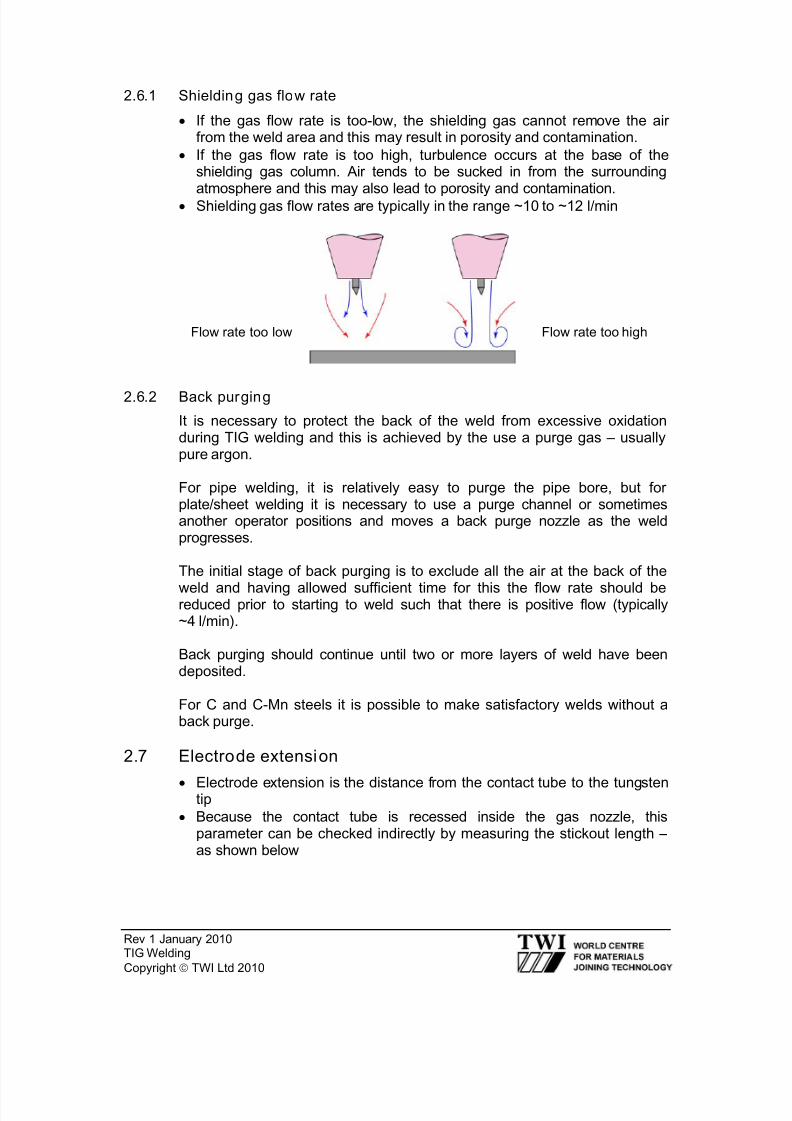
2.6.1 Shielding gas flow rate
• If the gas flow rate is too-low, the shielding gas cannot remove the airfrom the weld area and this may result in porosity and contamination.
• If the gas flow rate is too high, turbulence occurs at the base of theshielding gas column. Air tends to be sucked in from the surroundingatmosphere and this may also lead to porosity and contamination.
• Shielding gas flow rates are typically in the range ~10 to ~12 l/min
rate too low
2.6.2 Back purging
It is necessary to protect the back of the weld from excessive oxidationduring TIG welding and this is achieved by the use a purge gas – usuallypure argon.
For pipe welding, it is relatively easy to purge the pipe bore, but forplate/sheet welding it is necessary to use a purge channel or sometimesanother operator positions and moves a back purge nozzle as the weldprogresses.
The initial stage of back purging is to exclude all the air at the back of the
weld and having allowed sufficient time for this the flow rate should bereduced prior to starting to weld such that there is positive flow (typically~4 l/min).
Back purging should continue until two or more layers of weld have beendeposited.
For C and C-Mn steels it is possible to make satisfactory welds without aback purge.
2.7 Electrode extension
• Electrode extension is the distance from the contact tube to the tungstentip
• Because the contact tube is recessed inside the gas nozzle, thisparameter can be checked indirectly by measuring the stickout length –as shown below
Flow rate too low Flow rate too high

8/13/2019 12 Tig Welding
http://slidepdf.com/reader/full/12-tig-welding 6/8
Rev 1 January 2010TIG Welding
Copyright© TWI Ltd 2010
• If the electrode extension is too short, the electrode tip will not beadequately heated leading to an unstable arc
• If the electrode extension is too long, the electrode tip might overheat,cause melting and lead to tungsten inclusions
• As a general rule, stickout length should be 2 to 3 times the electrodediameter
3 Filler Wires
It is usual practice to use filler wires that have a similar composition to theparent metal but they may contain small additions of elements that willcombine with any oxygen and nitrogen present.
4 Tungsten Inclusions
Small fragments of tungsten that enter a weld will always show up onradiographs because of the relatively high density of this metal and for mostapplications will not be acceptable.
Thermal shock to the tungsten causing small fragments to enter the weldpool is a common cause of tungsten inclusions and is the reason whymodern power sources have a current slope-up device to minimise this risk.
This device allows the current to rise to the set value over a short period and
so the tungsten is heated more slowly and gently.
Electrodeextension
Stickout
8/13/2019 12 Tig Welding
http://slidepdf.com/reader/full/12-tig-welding 7/8
Rev 1 January 2010TIG Welding
Copyright© TWI Ltd 2010
5 Crater Cracking
Crater cracking is one form of solidification cracking and some filler metalscan be sensitive to it.
Modern power sources have a current slope-out device so that at the end of
a weld when the welder switches off the current it reduces gradually and theweld pool gets smaller and shallower.
This means that the weld pool has a more favourable shape when it finallysolidifies and crater cracking can be avoided.
6 Common Applications of the TIG Process
These include autogenous welding of longitudinal seams in thin walled pipesand tubes, in stainless steel and other alloys, on continuous forming mills.
Using filler wires, TIG is used for making high quality joints in heavier gauge
pipe and tubing for the chemical, petroleum and power generatingindustries.
It is also used in the aerospace industry for such items as airframes androcket motor cases.
7 Advantages of the TIG process
• Produces superior quality welds, with very low levels of diffusiblehydrogen so there is less danger of cold cracking.
• Does not give either weld spatter or slag inclusions which makes itparticularly suitable for applications that require a high degree of
cleanliness (eg pipework for the food and drinks industry, semiconductorsmanufacturing, etc).
• Can be used with filler metal and on thin sections without filler, it canproduce welds at relatively high speed.
• Enables welding variables to be accurately controlled and is particularlygood for controlling weld root penetration in all positions of welding.
• Can weld almost all weldable metals, including dissimilar joints, but it isnot generally used for those with low melting points such as lead and tin.The method is especially useful in welding the reactive metals with verystable oxides such as aluminium, magnesium, titanium and zirconium.
• The heat source and filler metal additions are controlled independentlyand thus it is very good for joining thin base metals.

8/13/2019 12 Tig Welding
http://slidepdf.com/reader/full/12-tig-welding 8/8
Rev 1 January 2010TIG Welding
Copyright© TWI Ltd 2010
8 Disadvantages of the TIG Process
• Gives low deposition rates compared with other arc welding processes.
• Need for higher dexterity and welder co-ordination than with MIG/MAG orMMA welding.
• Less economical than MMA or MIG/MAG for sections thicker than
~10mm.• Difficult to fully shield the weld zone in draughty conditions and so may
not be suitable for site/field welding
• Tungsten inclusions can occur if the electrode is allowed to contact theweld pool.
• The process does not have any cleaning action and so has low tolerancefor contaminants on filler or base metals.