(12) united states patent takizawa et al. (45) date of ...482,551 b1 * 1 1/2002 dhar et al. ... one...
TRANSCRIPT

(12) United States Patent Takizawa et al.
US007572555B2
US 7,572,555 B2 *Aug. 11, 2009
(10) Patent No.: (45) Date of Patent:
(54) HOLOGRAM RECORDING MATERIAL, HOLOGRAMRECORDING METHOD AND OPTICAL RECORDING MEDIUM
(75) Inventors: Hiroo Takizawa, Kanagawa (JP); Noriko Inoue, Kanagawa (JP)
(73) Assignee: FUJIFILM Corporation, Tokyo (JP)
(*) Notice: Subject to any disclaimer, the term of this patent is extended or adjusted under 35 U.S.C. 154(b) by 553 days.
This patent is Subject to a terminal dis claimer.
(21) Appl. No.: 11/237,986
(22) Filed: Sep. 29, 2005
(65) Prior Publication Data
US 2006/OO788O3 A1 Apr. 13, 2006
(30) Foreign Application Priority Data Sep. 30, 2004 (JP) ......................... P. 2004-28.6247
(51) Int. Cl. GO3H I/02 (2006.01) GO3C I/76 (2006.01)
(52) U.S. Cl. ............................ 430/1: 430/2; 430/280.1; 430/281. 1; 359/3
(58) Field of Classification Search ....................... None See application file for complete search history.
(56) References Cited
U.S. PATENT DOCUMENTS
3,615,454. A * 10, 1971 Cescon et al. ............... 430,292 5,151,520 A * 9, 1992 Gottschalk et al. .......... 126,638 5,202,221 A 4, 1993 Imai et al. ................ 430,283.1 5,665,494. A * 9/1997 Kawabata et al. .............. 430, 2
6, 140,384 A * 10/2000 Sorori et al. .................. 522, 12 6,482,551 B1 * 1 1/2002 Dhar et al. ..................... 430/1 6,740,466 B1* 5/2004 Matsumoto et al. ...... 430,270.1 7,112,616 B2 * 9/2006 Takizawa et al. ...... 522/8
2001/0026381 A1* 10, 2001 Shirakura et al. ............. 359/35 2004/0086803 A1* 5/2004 Takizawa et al. ....... 430,270.18 2004/0091816 A1* 5/2004 Matsumura et al. ...... 430,281.1 2004/0197670 A1* 10/2004 Takeyama ...................... 430/1 2004/0245432 A1* 12/2004 Takizawa ... ... 250,208.1 2005.0003133 A1 1/2005 Akiba et al. ............... 428,642 2005/00 19711 A1 1/2005 Takizawa .......... ... 430,561 2005, 0046915 A1 3/2005 Takizawa et al. ............... 359.3 2005/005891.0 A1 3/2005 Takizawa et al. ............... 430/1 2005/0068593 A1* 3/2005 Hayase et al. .................. 3.59.1 2005/021465.0 A1* 9, 2005 Takizawa et al. ............... 430/1 2005/0221198 A1* 10/2005 Takizawa et al. .. ... 430/1 2006/0057467 A1 3/2006 Takizawa ....................... 430/1 2006/0083890 A1* 4/2006 Takizawa ................... 428,641
(Continued) FOREIGN PATENT DOCUMENTS
JP T4015490 * 4f1974
(Continued) Primary Examiner Martin J Angebranndt (74) Attorney, Agent, or Firm Sughrue Mion, PLLC
(57) ABSTRACT
A hologram recording material is provided and includes at least a sensitizing dye capable of absorbing light having a hologram recording wavelength to generate an excited State thereof, and an interference fringe-recording component capable of recording interference fringes providing a refrac tive index modulation by an electron transfer or an energy transfer from the excited State, in which the sensitizing dye in the hologram recording material has a molar absorption coef ficient within a range of 1 to 10,000 at the hologram recording wavelength.
17 Claims, 1 Drawing Sheet
US 7,572,555 B2 Page 2
U.S. PATENT DOCUMENTS JP 03-050588 A 3, 1991 JP 05-046061 * 2/1993
2006/0188789 A1* 8, 2006 Takizawa et al. ............... 430, 1 JP 05-107999 A 4f1993 2006, O188790 A1* 8, 2006 Takizawa ... 430/1 JP 6-043634 A 2, 1994 2006/01941 22 A1* 8, 2006 Takizawa .... 430/1 JP 06-202543 * 7/1994 2007/0047038 A1* 3, 2007 Takizawa ... ... 359.3 JP 08-016O78 A 1, 1996 2007/004.8666 A1* 3, 2007 Takizawa ... 430,281.1 JP 11-512847. A 11, 1999 2007/0207390 A1* 9, 2007 Takizawa et al. ............... 430, 1 JP 2001-523842. A 11, 2001
WO WO 97/44365 A1 11, 1997 FOREIGN PATENT DOCUMENTS
JP O2-003O82 A 1, 1990 * cited by examiner

U.S. Patent Aug. 11, 2009 US 7,572,555 B2
FIG. 1
US 7,572,555 B2 1.
HOLOGRAM RECORDING MATERIAL, HOLOGRAMRECORDING METHOD AND
OPTICAL RECORDING MEDIUM
FIELD OF THE INVENTION
The present invention relates to a hologram recording material and a hologram recording method applicable to a high-density optical recording medium, a three-dimensional display, and a holographic optical element and the like.
BACKGROUND OF THE INVENTION
A general principle of hologram preparation are described in certain literatures and publishings, such as Junpei Tsujiu chi, “Holographic Display', published by Sangyo Tosho, chapter 2. In Such principle, one of two coherent laser beams irradiates an object to be recorded, and a hologram recording material is placed in a position capable of receiving a total reflected light therefrom. The hologram recording material is irradiated, in addition to the reflected light from the object, directly by the other coherent light beam which arrives with out going through the object. The reflected light from the object is called an object light, while the light directly irradi ating the recording material is called a reference light, and interference fringes of the reference light and the object light are recorded as image information. Then, when a light (repro ducing illumination light) same as the reference light irradi ates the processed recording material, it is so diffracted by the hologram as to reproduce a wave front of the reflected light when it at first reaches the recording material from the object at the recording, whereby an object image, substantially same as the real image of the object, can be viewed three-dimen sionally. A hologram prepared by introducing the reference light
and the object light from a same direction into the hologram recording material is called a transmission hologram. The interference fringes are formed perpendicularly or almost perpendicularly to the film Surface of the recording material, with a pitch of 1000-3000 fringes per millimeter. On the other hand, a hologram prepared by introducing the
reference light and the object light mutually from opposite sides of the hologram recording material is called a reflective hologram. The interference fringes are formed parallel or almost parallel to the film surface of the recording material, with a pitch of 3000-7000 fringes per millimeter.
The transmission hologram can be prepared by a known method described for example in JP-A-6-43634. Also the reflective hologram can be prepared by a known method described for example in JP-A-2-3082 and JP-A-3-50588.
Also, a hologram having a film thickness Sufficiently larger than the pitch of the interference fringes (usually a film thick ness of about 5 times or more of the pitch of the interference fringes or of about 1 um or larger) is called a Volume holo gram. On the other hand, a hologram having a film thickness of 5
times or less of the pitch of the interference fringes or of about 1 um or less is called a planar or Surface type hologram.
Also a hologram which records interference fringes by an absorption of a dye or silver is called an amplitude hologram, and a hologram which performs a recording by a surface relief formation or a refractive index modulation is called a phase hologram. The amplitude hologram is unfavorable in the effi ciency of light utilization because the light absorption signifi cantly decreases a diffraction efficiency or a reflection effi ciency of light, and a phase hologram is advantageously employed.
10
15
25
30
35
40
45
50
55
60
65
2 A Volume phase hologram can modulate a phase of light
without light absorption, by forming a plurality of interfer ence fringes different in the refractive index, instead of the optical absorption, in the hologram recording material.
In particular, the Volume phase hologram of reflective type is also called Lippman hologram, and is capable, by a wave length-selective reflection by Bragg's diffraction, of achiev ing a full-color image, a reproduction with white light and a high resolution, whereby a high-resolution full-color three dimensional display can be realized.
Also utilizing the wavelength-selective reflection, it is widely applied to holographic optical elements (HOE) such as a head-up display (HUD) for an automobile, a pickup lens for an optical disk, a head-mount display, a color filter for a liquid crystal display, and a reflecting plate for a reflective liquid crystal display.
In addition, it is commercially practiced or investigated in a lens, a diffraction grating, an interference filter, a coupler for an optical fiber, a photodeflector for a facsimile, a window pane material for a building and the like. On the other hand, the recent progress of so-called infor
mation Society rapidly promotes pervasiveness of networks Such as Internet and the high-visionTV. Also the broadcasting of the HDTV (high definition television) is planned shortly, and there is anticipated an increasing demand, also in con Sumer applications, for a high-density recording medium capable of recording image information of 100 GB or more inexpensively and easily.
Also the progress of the computers toward a higher capac ity is promoted, also in business applications such as com puter backup or broadcasting backup, a demand for an ultra high-density recording medium capable of inexpensively recording information of a large capacity of about 1 TB or more, at a high speed.
In Such trends, a compact and inexpensive optical record ing medium, being flexible and capable of random access, is considered promising in comparison with a magnetic tape incapable of random access or a hard disk which is not exchangeable and often causes failures. However, in an exist ing two-dimensional optical recording medium Such as DVD R, a storage capacity is limited to about 25 GB on one side at maximum because of the physical principle even if a short wavelength is employed for recording and reproduction, and a sufficiently large recording capacity capable of meeting the future demand cannot be anticipated.
Therefore, as an ultimate high-density recording medium, a three-dimensional optical recording medium which per forms recording in the direction of thickness is recently attracting attention. Promising candidates for Such a purpose include a method utilizing a two-photon absorbing material and a method utilizing holography (interference), and the Volume phase hologram recording material is being investi gated actively as a three-dimensional optical recording medium (holographic memory). A holographic memory utilizing a Volume phase hologram
recording material records a plurality of two-dimensional digital information (also called signal light) utilizing a spatial light modulator (SLM) such as DMD or LCD, instead of an object light reflected from a three-dimensional object. At the recording, there are performed multiplex recording such as an angular multiplexing, a phase multiplexing, a wavelength multiplexing or a shift multiplexing, thereby realizing a capacity as high as 1 TB. Also a readout operation is per formed with a CCD or a CMOS sensor, and a transfer rate as high as 1 Gbps can be realized by parallel writing and readout.

US 7,572,555 B2 3
However, requirements for the hologram recording mate rial for Such holographic memory are even stricter than those for application for a three-dimensional display oran HOE, as indicated in the following: (1) a high sensitivity; 5 (2) a high resolution; (3) a high diffraction efficiency of hologram; (4) a dry and rapid processing at the recording: (5) an ability for multiplex recording (a wide dynamic range); (6) a low shrinkage after recording; and (7) a satisfactory storability of hologram.
In particular, the requirement of (1) high sensitivity is chemically contradictory to those of (3) high diffraction effi ciency, (4) dry process, (6) low shrinkage after recording and (7) satisfactory storability, and it is difficult to satisfy these requirements at the same time. The known recording materials for the volume phase holo
gram include, as a write-once type, a bichromate gelatin system, a bleached silver halide system and a photopolymer system, and, as a rewritable type, a photorefractive system and a photochromic polymer System.
However, among these known recording materials for the Volume phase hologram, particularly for the application for a high sensitivity optical recording medium, there has not been known a material that can satisfy all the requirements and an improvement is being desired. More specifically, for example the bichromate gelatin sys
tem has the advantages of a high diffraction efficiency and low noise characteristics, but is associated with drawbacks of an extremely poor storability and a low sensitivity and requir ing a wet process, thus being unsuitable for use in the holo graphic memory. The bleached silver halide system has an advantage of a
high sensitivity, but requires a wet process with a cumber Some bleaching process and is associated with drawbacks of a large scattering and a poor light fastness, thus being gener ally unsuitable for use in the holographic memory. The photorefractive material has an advantage of being
rewritable, but has drawbacks of requiring an application of a 40 high electric field at the recording and of a poor storability of record.
Also a photochromic polymer system represented by an aZobenzene polymer material has an advantage of rewritabil ity, but is associated with drawbacks of an extremely low sensitivity and a poor storability of record. For example WO 97/44365 A1 discloses a rewritable hologram recording material utilizing an anisotropy in refractive index and an alignment control in an azobenzene polymer (photochromic polymer), but such material is far from practical use because of an extremely low sensitivity as it has a low quantum yield in the isomerization of azobenzene and involves an alignment control, and also of a poor storability of record as a trade-off of rewritability. Among these, a dry process photopolymer System dis
closed in JP-A-6-43634, JP-A-2-3082 and JP-A-3-50588 employs a basic composition of a binder, a radical polymer izable monomer and a photopolymerization initiator and cre ates a difference in the refractive index by employing a com pound having an aromatic ring, chlorine or bromine in either of the binder and the radical polymerizable monomer in order to increase the refractive index modulation, whereby the polymerization proceeds with a concentration of the mono mer in light parts of the interference fringes and a concentra tion of the binder in dark parts of the interference fringes, formed at the holographic exposure, thereby genrating a dif ference in the refractive index. Therefore, it can be considered
10
25
30
35
45
50
55
60
65
4 as a relatively practical system in which a high diffraction efficiency and a dry process can be realized at the same time.
However, such a system involves drawbacks of a poor sensitivity of about /1000 in comparison with the bleached silverhalide system, a necessity for a heat fixing treatment as long as almost 2 hours for improving the diffraction effi ciency, an inhibition by oxygen of the involved radical poly merization, and a shrinkage of the recording material after exposure and fixation thereby resulting in a change in diffrac tion wavelength and angle at the reproducing operation, and is hardly usable in the application for a holographic memory.
In general, in comparison with a radical polymerization, a cationic polymerization, particularly a ring-opening cationic polymerization of an epoxy compound or the like, shows a Smaller shrinkage after polymerization, also is not subjected to an inhibition of polymerization by oxygen, and provides a film with a rigidity. It is therefore pointed out that a cationic polymerization is more Suitable for the application as a holo graphic memory.
For example, JP-A-5-107999 and JP-A-8-16078 disclosea hologram recording material employing a cationic polymer izable compound (monomer or oligomer) instead of a binder, and further combining a sensitizing dye, a radical polymer ization initiator, a cationic polymerization initiator and a radi cal polymerizable compound.
Also JP-T-2001-523842 and JP-T-11-512847 disclose a hologram recording material not utilizing a radical polymer ization but employing a sensitizing dye, a cationic polymer ization initiator, a cationic polymerizable compound and a binder only.
However, these cationic polymerization systems, though showing an improvement in the shrinkage rate in comparison with the radical polymerization system, show a decreased sensitivity as a trade-off, which will lead to a major drawback in the transfer rate in the practice. These systems also show a lowered diffraction efficiency, which will lead to drawbacks in an S/N ratio and a multiplex recordability. As the photopolymer system involves a material transfer, in
the application to a holographic memory, there results a dilemma as explained in the foregoing that an improved storability and a reduced shrinkage lead to a decreased sen sitivity (cationic polymerization system) and an improved sensitivity leads to a loss in the storability and the shrinkage (radical polymerization system).
Also in order to increase the recording density of a holo graphic memory, there is required multiplex recording of 50 times or more and preferably 100 times or more, and, in the photopolymer system utilizing a polymerization process involving a material transfer for recording, the recording speed becomes lower in a latter stage of the multiplex record ing where a large proportion of the compound has already polymerized in comparison with an initial stage of the mul tiplex recording, and it is practically difficult to regulate the exposure amount and to obtain a wide dynamic range by controlling Such difference in the recording speed. The aforementioned trade-off among a high sensitivity, a
satisfactory storability, a low shrinkage and a dry process, and the limitation in the multiplex recordability (high recording density) are difficult to avoid, because of the physical laws, within the related-art photopolymer system. It is also difficult to meet the requirements for the holographic memory in the silverhalide system, particularly in principle inachieving dry process.
Therefore, in order to apply a hologram recording material to a holographic memory, it is strongly desired to develop a totally novel recording method capable of fundamentally resolving Such drawbacks, particularly attaining a high sen
US 7,572,555 B2 5
sitivity, a low shrinkage, a satisfactory storability, a dry pro cessability and a multiplex recordability at the same time.
Also in the related-art applications of the display hologram or the holographic optical element, a film thickness of the hologram recording material can be several tens of microme ters or less, but, in the holographic memory, there is required a film thickness of 100 um or larger, and as large as 500 um to 1 mm in certain cases, in order to attain a multiplicity (record ing density). For increasing the multiplicity, the hologram recording light has to be transmitted much even in Such film thickness, but the known sensitizing dye generally has a molar absorption coefficient as large as 10,000 to 100,000 at the hologram recording wavelength. Therefore, for attaining a high transmittance at Such film thickness, an amount of addition of the sensitizing dye has to be maintained at an extremely low level, thus resulting in a significant loss in the sensitivity.
SUMMARY OF THE INVENTION
An object of an illustrative, non-limiting embodiment of the present invention is to provide a hologram recording material and a hologram recording method capable of attain ing a high sensitivity, a high diffraction efficiency, a satisfac tory storability, a low shrinkage, a dry processability and a multiplex recording property (high recording density) at the same time and applicable to a high-density optical recording medium, a three-dimensional display, a holographic optical element and the like. It is also to provide, for attaining a high recording density by multiplex recording of a large number especially in a high-density optical recording medium, a sen sitizing dye which transmits a large amount of the hologram recording light and can be used with a high sensitivity even in a thick hologram recording material with a film thickness of 100 um or larger, or 500 um or larger. As a result of intensive investigations of the present inven
tors, the objectives of the present invention have been attained by following means. (1) A hologram recording material characterized by including
at least a sensitizing dye capable of absorbing light having a hologram recording wavelength to generate an excited state thereof, and an interference fringe-recording compo nent capable of recording interference fringes providing a refractive index modulation by an electron or energy trans fer from the excited State, and in that the sensitizing dye in the hologram recording material has a molar absorption coefficient within a range of 1 to 10,000 at the hologram recording wavelength.
(2) A hologram recording material described in (1), charac terized in that the sensitizing dye in the hologram recording material has a molar absorption coefficient within a range of 1 to 5,000 at the hologram recording wavelength.
(3) A hologram recording material described in (1) or (2), characterized in that the sensitizing dye in the hologram recording material has a molar absorption coefficient within a range of 5 to 2,500 at the hologram recording wavelength.
(4) A hologram recording material described in any one of (1) to (3), characterized in that the sensitizing dye in the holo gram recording material has a molar absorption coefficient within a range of 10 to 1,000 at the hologram recording wavelength.
(5) A hologram recording material described in any one of (1) to (4), characterized in that the sensitizing dye in the holo gram recording material has an absorption maximum within a region shorter in wavelength than the hologram recording wavelength by 20 to 100 nm.
5
10
15
25
30
35
40
45
50
55
60
65
6 (6) A hologram recording material described in any one of (1)
to (5), characterized in that the sensitizing dye in the holo gram recording material has an absorption maximum within a region shorter in wavelength than the hologram recording wavelength by 25 to 50 nm.
(7) A hologram recording material described in any one of (1) to (6), characterized in that the sensitizing dye in the holo gram recording material has a molar absorption coefficient equal to or less than /s of the molar absorption coefficient at an absorption maximum thereof
(8) A hologram recording material described in any one of (1) to (7), characterized in that the sensitizing dye in the holo gram recording material has a molar absorption coefficient equal to or less than /10 of the molar absorption coefficient at an absorption maximum thereof.
(9) A hologram recording material described in any one of (1) to (8), characterized in that the sensitizing dye in the holo gram recording material has a molar absorption coefficient equal to or less than /20 of the molar absorption coefficient at an absorption maximum thereof.
(10) A hologram recording material described in any one of (1) to (9), characterized in that the sensitizing dye in the hologram recording material has a molar absorption coef ficient equal to or less than /so of the molar absorption coefficient at an absorption maximum thereof.
(11) A hologram recording material described in any one of (1) to (10), characterized in that the sensitizing dye is a Ru complex dye, a ferrocene derivative, a cyanine dye or a merocyanine dye.
(12) A hologram recording material described in any one of (1) to (11), characterized in that the sensitizing dye is a cyanine dye or a merocyanine dye.
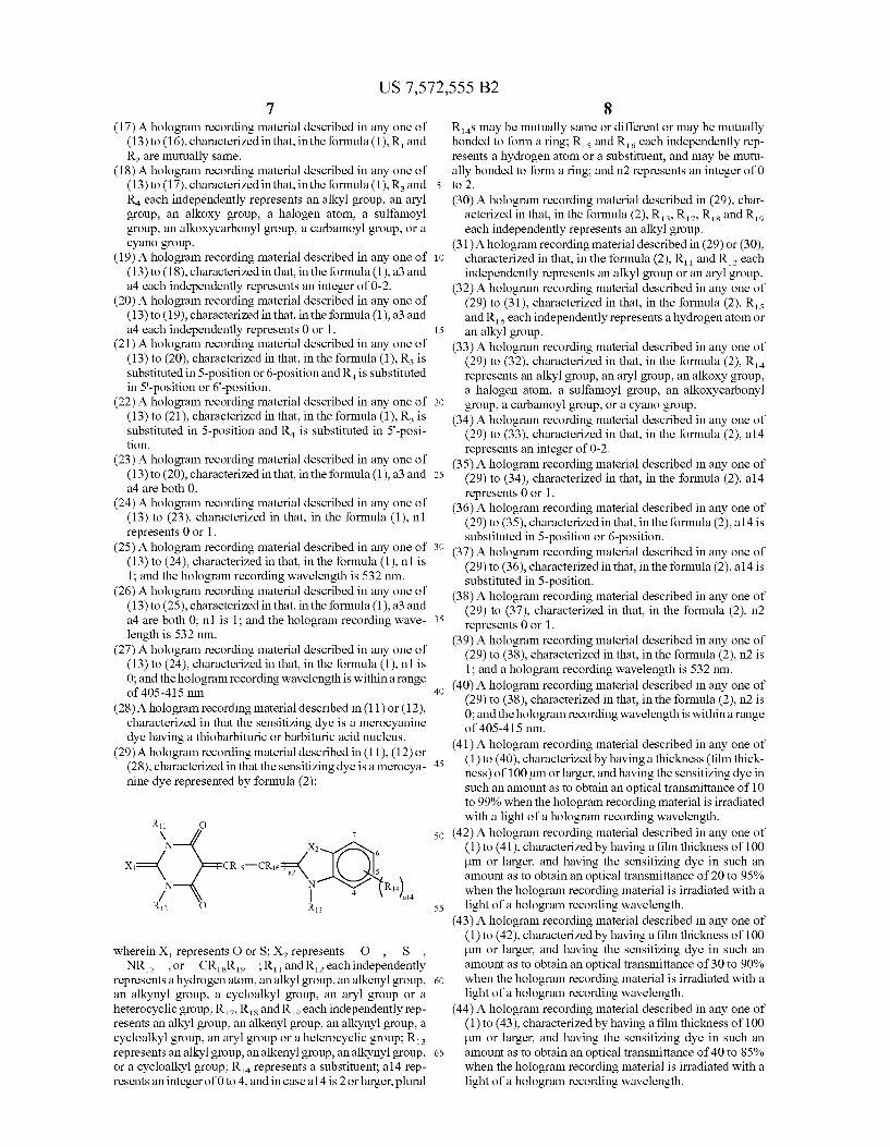
(13) A hologram recording material described in any one of (1) to (12), characterized in that the sensitizing dye is a cyanine dye represented by formula (1):
7 7.
6 O O 6
IOC)-cis-cr-O. (R3)a3 Nt N (R4)a4 4 4.
Cly R R
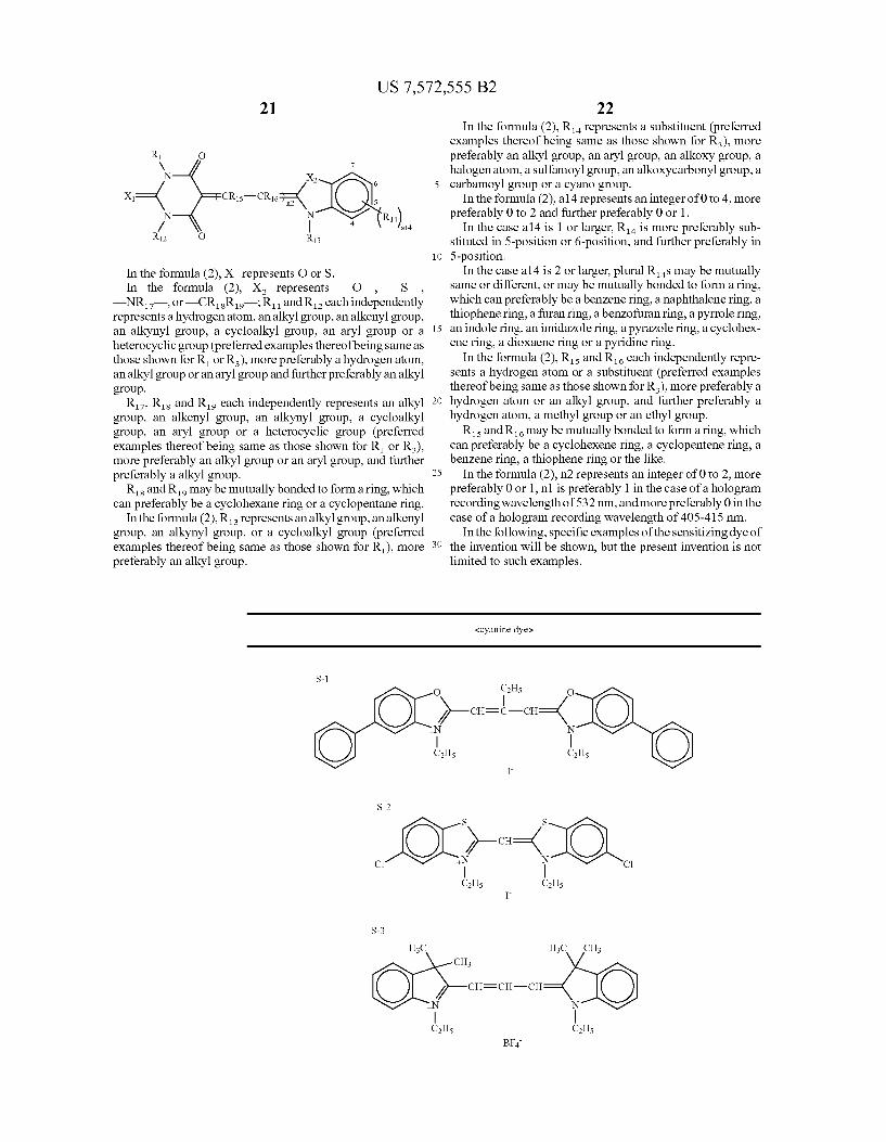
wherein R and R. each independently represents an alkyl group, an alkenyl group, an alkynyl group or a cycloalkyl group; R and Reachindependently represents a Substituent; and a3 and a4 each independently represents an integer of 0 to 4, and in case a3 or a4 is 2 or larger, plural RS or RS may be mutually same or different or may be mutually bonded to form a ring; Rs. Re and R, each independently represents a hydrogenatom or a substituent, and may be mutually bonded to form a ring; n1 represents an integer of 0 to 2: CI represents a charge neutralizing ion; and y represents a number required for neutralizing the charge. (14) A hologram recording material described in (13), char
acterized in that, in the formula (1), Rs. R and R, each independently represents a hydrogen atom or an alkyl group.
(15) A hologram recording material described in (13) or (14), characterized in that, in the formula (1), Rs. RandR, each independently represents a hydrogenatom, a methyl group or an ethyl group.
(16) A hologram recording material described in any one of (13) to (15), characterized in that, in the formula (1), R and Reach independently represents a an alkyl group.
US 7,572,555 B2 7
(17) A hologram recording material described in any one of (13) to (16), characterized in that, in the formula (1), R and R2 are mutually same.
(18) A hologram recording material described in any one of (13) to (17), characterized in that, in the formula (1), R and Reach independently represents an alkyl group, an aryl group, an alkoxy group, a halogen atom, a Sulfamoyl group, an alkoxycarbonyl group, a carbamoyl group, or a cyano group.
(19) A hologram recording material described in any one of (13) to (18), characterized in that, in the formula (1), a3 and a4 each independently represents an integer of 0-2.
(20) A hologram recording material described in any one of (13) to (19), characterized in that, in the formula (1), a3 and a4 each independently represents 0 or 1.
(21) A hologram recording material described in any one of (13) to (20), characterized in that, in the formula (1), R is substituted in 5-position or 6-position and R is substituted in 5'-position or 6'-position.
(22) A hologram recording material described in any one of (13) to (21), characterized in that, in the formula (1), R is substituted in 5-position and R is substituted in 5'-posi tion.
(23) A hologram recording material described in any one of (13) to (20), characterized in that, in the formula (1), a3 and a4 are both 0.
(24) A hologram recording material described in any one of (13) to (23), characterized in that, in the formula (1), n1 represents 0 or 1.
(25) A hologram recording material described in any one of (13) to (24), characterized in that, in the formula (1), n1 is 1; and the hologram recording wavelength is 532 nm.
(26) A hologram recording material described in any one of (13) to (25), characterized in that, in the formula (1), a3 and a4 are both 0; n1 is 1; and the hologram recording wave length is 532 nm.
(27) A hologram recording material described in any one of (13) to (24), characterized in that, in the formula (1), n1 is 0; and the hologram recording wavelength is within a range of 405-415 nm.
(28) A hologram recording material described in (11) or (12), characterized in that the sensitizing dye is a merocyanine dye having a thiobarbituric or barbituric acid nucleus.
(29) A hologram recording material described in (11), (12) or (28), characterized in that the sensitizing dye is a merocya nine dye represented by formula (2):
R11 O V 7 N
X—( CRs CR16 n2 5 N N R!) / 4 al4
R12 O R13
wherein X represents O or S: X represents —O— —S , —NR7—, or—CRR : R and Reachindependently represents a hydrogenatom, an alkyl group, an alkenyl group, an alkynyl group, a cycloalkyl group, an aryl group or a heterocyclic group; R7, Rs and Rio each independently rep resents an alkyl group, an alkenyl group, an alkynyl group, a cycloalkyl group, an aryl group or a heterocyclic group; R. represents an alkyl group, an alkenyl group, an alkynyl group, or a cycloalkyl group; R represents a Substituent; a 14 rep resents an integer of 0 to 4, and in case a14 is 2 or larger, plural
5
10
15
25
30
35
40
45
50
55
60
65
8 Ras may be mutually same or different or may be mutually bonded to form a ring; Rs and Reach independently rep resents a hydrogen atom or a Substituent, and may be mutu ally bonded to form a ring; and n2 represents an integer of 0 to 2. (30) A hologram recording material described in (29), char
acterized in that, in the formula (2), R. R. R. and Rio each independently represents an alkyl group.
(31) A hologram recording material described in (29) or (30), characterized in that, in the formula (2), R and Reach independently represents an alkyl group or an aryl group.
(32) A hologram recording material described in any one of (29) to (31), characterized in that, in the formula (2), Ris and Reach independently represents a hydrogenatom or an alkyl group.
(33) A hologram recording material described in any one of (29) to (32), characterized in that, in the formula (2), R. represents an alkyl group, an aryl group, an alkoxy group, a halogen atom, a Sulfamoyl group, an alkoxycarbonyl group, a carbamoyl group, or a cyano group.
(34) A hologram recording material described in any one of (29) to (33), characterized in that, in the formula (2), a 14 represents an integer of 0-2.
(35) A hologram recording material described in any one of (29) to (34), characterized in that, in the formula (2), a 14 represents 0 or 1.
(36) A hologram recording material described in any one of (29) to (35), characterized in that, in the formula (2), a 14 is substituted in 5-position or 6-position.
(37) A hologram recording material described in any one of (29) to (36), characterized in that, in the formula (2), a 14 is substituted in 5-position.
(38) A hologram recording material described in any one of (29) to (37), characterized in that, in the formula (2), n2 represents 0 or 1.
(39) A hologram recording material described in any one of (29) to (38), characterized in that, in the formula (2), n2 is 1; and a hologram recording wavelength is 532 nm.
(40) A hologram recording material described in any one of (29) to (38), characterized in that, in the formula (2), n2 is 0; and the hologram recording wavelength is withina range of 405-415 nm.
(41) A hologram recording material described in any one of (1) to (40), characterized by having a thickness (film thick ness) of 100 um or larger, and having the sensitizing dye in Such an amount as to obtain an optical transmittance of 10 to 99% when the hologram recording material is irradiated with a light of a hologram recording wavelength.
(42) A hologram recording material described in any one of (1) to (41), characterized by having a film thickness of 100 um or larger, and having the sensitizing dye in Such an amount as to obtain an optical transmittance of 20 to 95% when the hologram recording material is irradiated with a light of a hologram recording wavelength.
(43) A hologram recording material described in any one of (1) to (42), characterized by having a film thickness of 100 um or larger, and having the sensitizing dye in Such an amount as to obtain an optical transmittance of 30 to 90% when the hologram recording material is irradiated with a light of a hologram recording wavelength.
(44) A hologram recording material described in any one of (1) to (43), characterized by having a film thickness of 100 um or larger, and having the sensitizing dye in Such an amount as to obtain an optical transmittance of 40 to 85% when the hologram recording material is irradiated with a light of a hologram recording wavelength.
US 7,572,555 B2
(45) A hologram recording material described in any one of (1) to (44), characterized by having a film thickness of 200 um or larger.
(46) A hologram recording material described in any one of
10 latent image of the color developed substance with light of a wavelength region, which is different from that of the holographic exposure, to cause a polymerization reaction, in which these steps are performed in dry process.
(1) to (45), characterized by having a film thickness of 500 5 (51) A hologram recording material described in (50), char um or larger.
(47) A hologram recording material described in any one of (1) to (46), characterized in that the interference fringe recording component is a component capable of recording interference fringes providing a refractive index modula tion by at least one of 1) a polymerization reaction, 2) a color developing reaction, 3) a color developing reaction amplified by a self-sensitization with a color developed Substance of a latent image, 4) a polymerization reaction sensitized with a color developed substance of a latent image, 5) an alignment change in a compound having a specific birefringence, 6) a color erasing reaction of a dye, and 7) a latent image-sensitized polymerization reaction sensitized by a latent image of a residual of a color-erasable dye.
(48) A hologram recording material described in (47), char acterized in that the interference fringe-recording compo nent is a component capable of recording the interference fringes by 3) the color developing reaction amplified by the self-sensitization with the color developed substance of the latent image, and in that the component records the inter ference fringes by: a first step of generating a color devel oped Substance as a latent image by holographic exposure, the color developed substance having no absorption in a wavelength of a hologram reproducing light; and a second step of irradiating the latent image of the color developed substance with light of a wavelength region, which is dif ferent from that of the holographic exposure and in which the sensitizing dye has a molar absorption coefficient of 5,000 or less, to self-sensitize and self-amplify the color developed substance, in which these steps are performed in dry process.
(49) A hologram recording material described in (47) or (48), characterized by including, as a group of compounds capable of a hologram recording by at least one of 2) the color developing reaction and 3) the color developing reac tion amplified by the self-sensitization with the color developed substance of the latent image, described in (47), at least: 1) a sensitizing dye capable of absorbing light upon holo
graphic exposure thereby generating an excited State thereof, and
2) an interference fringe-recording component containing a dye precursor capable of forming a color developed Substance having an absorption shifted to a longer wave length than that in an original State and having no absorption in a wavelength of a hologram reproducing light, and capable of recording interference fringes pro viding a refractive index modulation through a color development by an electron or energy transfer from the excited State of the sensitizing dye or from an excited state of the color developed substance.
(50) A hologram recording material described in (47), char acterized in that the interference fringe-recording compo nent is a component capable of recording the interference fringes by 4) the polymerization reaction sensitized with the color developed Substance of the latent image, and in that the component records the interference fringes by: a first step of generating a color developed Substance as a latent image by holographic exposure, the color developed Substance having no absorption in a wavelength of a holo gram reproducing light; and a second step of irradiating the
10
15
25
30
35
40
45
50
55
60
65
acterized by including, as a group of compounds capable of a hologram recording, at least: 1) a sensitizing dye capable of absorbing light upon holo
graphic exposure in the first step thereby generating an excited state thereof;
2) a dye precursor capable of forming a color developed Substance having an absorption shifted to a longer wave length than that in an original state, also having an absorption in a wavelength region in which the sensitiz ing dye has a molar absorption coefficient of 5,000 or less and having no absorption in a wavelength of a holo gram reproducing light, by an electron or energy transfer from the excited state of the sensitizing dye in the first step or from an excited state of the color developed Substance in the second step;
3) a polymerization initiator capable of initiating a poly merization of a polymerizable compound by an electron or energy transfer from an excited State of the sensitizing dye in the first step or from an excited state of the color developed substance in the second step;
4) a polymerizable compound; and 5) a binder.
(52) A hologram recording material described in (47), char acterized by including, as a group of compounds capable of hologram recording by 6) thecolor erasing reaction of the dye, at least: 1) a sensitizing dye capable of absorbing light upon holo
graphic exposure thereby generating an excited State; and
2) a color-erasable dye, or a color-erasing agent precursor and a color-erasable dye, as an interference fringe-re cording component;
in which the sensitizing dye generates an excited State thereof by holographic exposure, and performs an energy or electron transfer directly to the color-erasable dye to cause a color erasure thereof or performs an energy transfer or an electron transfer to the color-erasing agent precursor to generate a color-erasing agent which causes a colorerasure of the color erasable dye, thereby forming interference fringes providing a refractive index modulation; and
in that the color-erasing agent precursor is at least one of a radical generator, an acid generator, a base generator, a nucleophilic agent generator, an electrophilic agent generator or a triplet oxygen. (53) A hologram recording material described in (47) or (52),
characterized in that the interference fringe-recording component is a component capable of recording the inter ference fringes by 7) the latent image-sensitized polymer ization reaction sensitized by the latent image of the residual of the color-erasable dye, and in that the compo nent records the interference fringes by: a first step in which a sensitizing dye having an absorption at a wave length of holographic exposure (i.e., a hologram recording wavelength) absorbs light upon the holographic exposure thus generating an excited State thereof, and performs an energy or electron transfer directly to a color-erasable dye to cause a color erasure thereof or performs an energy transfer or an electron transfer to a color-erasing agent precursor described in (52) to generate a color-erasing agent which causes a color erasure of the color-erasable dye, thereby forming a latent image of a residual of the
US 7,572,555 B2 11
color-erasable dye; and a second step of irradiating the latent image of the residual of the color-erasable dye with light of a wavelength region, which is different from that of the holographic exposure, to activate a polymerization ini tiator by an energy or electron transfer thereby generating 5 a polymerization reaction.
(54) A hologram recording material described in (53), char acterized by including, as a group of compounds capable of a hologram recording, at least: 1) a sensitizing dye capable of absorbing light upon holo- 10
graphic exposure in the first step thereby generating an excited state thereof;
2) a color-erasable dye having a molar absorption coeffi cient of 1,000 or less at a wavelength of a hologram reproducing light, capable of a color erasure as a result, 15 in the first step, of an energy or electron transfer directly from the excited State of the sensitizing dye or of gen eration of the color-erasing agent by an energy or elec tron transfer to the color-erasing agent precursor,
3) a polymerization initiator capable of initiating a poly- 20 merization of a polymerizable compound by an electron transfer or an energy transfer in the second step from an excited state of a residual of the color-erasable dye, in which the polymerization initiator may serve as 2) the color-erasing agent precursor; 25
4) a polymerizable compound; and 5) a binder.
(55) A hologram recording material described in any one of (1) to (54), characterized by including an electron-donat ing compound capable of reducing a radical cation of the sensitizing dye.
(56) A hologram recording material described in (55), char acterized in that the electron-donating compound is an alkylamine, an aniline, a phenylenediamine, a tripheny lamine, a carbazole, a phenothiazine, a phenoxazine, a phenazine, a hydroquinone, a cathecol, an alkoxybenzene, an aminophenol, an imidazole, a pyridine, a metallocene, a metal complex, or semiconductor fine particles.
(57) A hologram recording material described in (55) or (56), characterized in that the electron-donating compound is a triphenylamine, a phenothiazine, a phenoxazine, or a phenazine.
(58) A hologram recording material described in any one of (55) to (57), characterized in that the electron-donating as compound is a phenothiazine.
(59) A volume phase hologram recording material character ized by performing a Volume phase hologram recording with a hologram recording material described in any one of
30
35
40
12 (62) A hologram recording method by 3) the color developing
reaction amplified by the self-sensitization with the color developed substance of the latent image described in (61), characterized by including at least: a first step of generating a color developed substance, having no absorption in a wavelength of a hologram reproducing light, as a latent image by holographic exposure; and a second step of irra diating the latent image of the color developed Substance with light of a wavelength region, which is different from that of the holographic exposure and in which the sensitiz ing dye has a molar absorption coefficient of 5,000 or less, to generate a color developed Substance by a self-sensitized amplification thereby recording the interference fringes providing the refractive index modulation, and in that these steps are performed in dry process.
(63) A hologram recording method by 4) the polymerization reaction sensitized with the color developed substance of the latent image described in (61), characterized by includ ing at least: a first step of generating a color developed Substance, having no absorption in a wavelength of a holo gram reproducing light, as a latent image by holographic exposure; and a second step of irradiating the latent image of the color developed substance with light of a wavelength region, which is different from that of the holographic exposure, to generate a polymerization reaction thereby recording the interference fringes providing the refractive index modulation, and in that these steps are performed in dry process.
(64) A hologram recording method by 7) the latent image sensitized polymerization reaction sensitized by the latent image of the residual of the color-erasable dye described in (61), characterized by including at least: a first step in which a sensitizing dye having an absorption at a wave length of holographic exposure absorbs light upon the holographic exposure thus generating an excited State thereof, and performs an energy or electron transfer directly to a color-erasable dye to cause a color erasure thereof or performs an energy or electron transfer to a color-erasing agent precursor described in (52) to generate a color-erasing agent which causes a color erasure of the color-erasable dye, thereby forming a latent image of a residual of the color-erasable dye; and a second step of irradiating the latent image of the residual of the color erasable dye with light of a wavelength region, which is different from that of the holographic exposure, to activate a polymerization initiator by an energy or electron transfer thereby initiating a polymerization reaction and recording the interference fringes providing the refractive index modulation.
(1) to (58). 50 (65) A hologram recording method utilizing a hologram (60) A hologram recording material described in any one of
(1) to (59), characterized in that the hologram recording in (1) to (59) is an unrewritable recording (the recorded inter ference fringes is unrewritable).
(61) A hologram recording method, characterized in that an 55 interference fringe-recording component according to any one of (1) to (60) records interference fringes providing a refractive index modulation by at least one of 1) a poly merization reaction, 2) a color developing reaction, 3) a color developing reaction amplified by a self-sensitization 60 with a color developed substance of a latent image, 4) a polymerization reaction sensitized with a color developed Substance of a latent image, 5) an alignment change in a compound having a specific birefringence, 6) a color eras ing reaction of a dye, and 7) a latent image-sensitized 65 polymerization reaction sensitized by a latent image of a residual of a color-erasable dye.
recording material described in any one of (1) to (60) or described in any one of (61) to (64), characterized in that a multiplex recording is performed by effecting the holo graphic exposure 10 times or more.
(66) A hologram recording method described in (65), char acterized in that the multiplex recording are performed under a constant exposure amount in each holographic exposure.
(67) A hologram recording method described in any one of (61) to (66), characterized by not performing the holo graphic exposure in wet process. A hologram recording material enabling Such process.
(68) A hologram recording material described in any one of (1) to (60), characterized in that a light-shielding filter capable of cutting off a part of ultraviolet, visible and infrared wavelength regions other than those of a recording light and a reproducing light is provided on a front Surface

US 7,572,555 B2 13
and/or a rear Surface of the hologram recording material described in any one of (1) to (60).
(69) An optical recording medium including a hologram recording material described in any one of (1) to (60) and (66).
(70) An optical recording medium described in (69), charac terized in that a hologram recording material described in any one of (1) to (60) and (66) is stored in a light-shielding cartridge.
(71) A three-dimensional display hologram utilizing a holo gram recording material described in any one of (1) to (60) and (66), and a producing method for a three-dimensional display hologram utilizing a hologram recording method described in any one of (61) to (65).
(72) A holographic optical element including a hologram recording material described in any one of (1) to (60) and (66). A producing method for a holographic optical ele ment including a hologram recording method described in any one of (61) to (65). The present invention allows to provide a hologram record
ing material and a hologram recording method capable of attaining a high sensitivity, a high diffraction efficiency, a satisfactory storability, a low shrinkage, a dry processability and a multiplex recording property (high recording density) at the same time and applicable to a high-density optical recording medium, a three-dimensional display, a holo graphic optical element and the like. It also provides a holo gram recording material capable, by employing a sensitizing dye satisfying requirements of the invention, particularly in a high-density optical recording medium, of a high sensitivity recording even in a thick hologram recording material of a thickness of 100 um or larger and also attaining a high record ing density by a large number of multiplex recording.
BRIEF DESCRIPTION OF THE DRAWING
The sole FIGURE shows an outline view for explaining the two-beam optical system for holographic exposure. The description of numerical references in the FIGURE is set forth below.
10 YAG laser 12 laser beam 14 mirror 2O beam splitter 22 beam segment 24 mirror 26 spatial filter 40 beam expander 30 hologram recording material 28 sample 32 He–Ne laser beam 34 He–Ne laser 36 detector 38 rotary stage
DETAILED DESCRIPTION OF THE INVENTION
In the following, exemplary embodiments of a hologram recording method and a hologram recording material of the present invention will be explained in detail. A hologram recording material of the invention is charac
terized by including at least a sensitizing dye capable of absorbing light having a hologram recording wavelength to generate an excited State thereof, and an interference fringe recording component capable of recording interference
5
10
15
25
30
35
40
45
50
55
60
65
14 fringes as a refractive index modulation by an electron or energy transfer from the excited State, and in that the sensi tizing dye in the hologram recording material has a molar absorption coefficient within a range of 1 to 10,000 at the hologram recording wavelength. The hologram recording material of the present invention
preferably records interference fringes providing a refractive index modulation by any one of 1) a polymerization reaction, 2) a color developing reaction, 3) a color developing reaction amplified by a self-sensitization with a color developed sub stance of a latent image, 4) a polymerization reaction sensi tized with a color developed Substance of a latent image, 5) an alignment change in a compound having a specific birefrin gence, 6) a color erasing reaction of a dye, and 7) a latent image-sensitized polymerization reaction sensitized by a latent image of a residual of a color-erasable dye (a residual color-erasable dye); preferably by any one of2) a color devel oping reaction, 3) a color developing reaction amplified by a self-sensitization with a color developed substance of a latent image, 4) a polymerization reaction sensitized with a color developed substance of a latent image, 6) a color erasing reaction of a dye, and 7) a latent image-sensitized polymer ization reaction sensitized by a latent image of a residual color-erasable dye; and more preferably by any one of 2) a color developing reaction, 4) a polymerization reaction sen sitized with a color developed Substance of a latent image, 6) a color erasing reaction of a dye, and 7) a latent image sensitized polymerization reaction sensitized by a latent image of a residual color-erasable dye, The hologram recording material of the present invention
preferably does not is used in wet process. The hologram recording material of the present invention
is preferably an unrewritable system. The unrewritable sys tem indicates a system which is recorded by an irreversible reaction and in which the data once recorded can be stored without being rewritten even in a rewriting operation by over writing. It is therefore suitable for storage of data that are important and require a prolonged storage. It is however naturally possible to perform a new recording in an area that is not yet recorded. For this reason, it is generally called a “add-on type' or a “write once” type.
Light to be employed in the hologram recording of the invention is preferably any one of an ultraviolet light; a visible light and an infrared light within a wavelength region of 200 to 2,000 nm, more preferably an ultraviolet light or a visible light of a wavelength of 300 to 700 nm, and further preferably a visible light of a wavelength of 400 to 700 nm.
Also a chemically active radiation in the invention is pref erably a coherent laser light (aligned in phase and wave length). The laser to be employed can be a solid-state laser, a semiconductor laser, a gas laser or a liquid laser, and preferred examples of the laser light include a second harmonic wave of 532 nm of a YAG laser, a third harmonic wave of 355 nm of a YAG laser, a light of a GaN laser of about 405-415 nm, a light of an Arion laser of 488 or 515 nm, a light of a He—Ne laser of 632 or 633 nm, a light of a Krion laser of 647 nm, a light ofa ruby laser of 694 nm, and a light of a He—Cd laser of 636, 634, 538, 534 or 442 nm.
Also a pulsed laser of nanosecond or picosecond order can be employed preferably.
In the case of employing the hologram recording material as an optical recording medium, a second harmonic wave of 532 nm of a YAG laser, or a light of a GaN laser of about 405-415 nm is preferably employed.
With respect to the wavelength of the light employed in the holographic exposure (hologram recording), the light for
US 7,572,555 B2 15
hologram reproduction preferably has a same or longer wave length, more preferably a same wavelength.
In the hologram recording material of the invention, after the holographic exposure, a fixing step may be performed by light and/or heat.
Particularly in the case of utilizing an acid amplifier or a base amplifier in the hologram recording material of the invention, heating is preferably employed in the fixation also in causing an effective function of the acid amplifier or the base amplifier.
Also in the case of an optical fixation, the entire Surface of the hologram recording material is irradiated with an ultra violet light or a visible light (non-interfering exposure). Pre ferred examples of a light source to be employed include a visible light laser, an ultraviolet light laser, a carbon arc lamp, a high-pressure mercury lamp, a Xenon lamp, a metal halide lamp, a fluorescent lamp, a tungsten lamp, an LED and an organic EL.
In the case ofathermal fixation, the fixing step is preferably performed at 40-160° C., more preferably at 60-130° C.
In the case of performing both an optical fixation and a thermal fixation, the light and the heat may be applied simul taneously or separately.
In the recording of the interference fringes, an amount of refractive index modulation is preferably 0.00001 to 0.5, more preferably 0.0001 to 0.3. The amount of refractive index modulation is preferably smaller for a larger film thickness of the hologram recording material, and is preferably larger for a smaller film thickness of the hologram recording material.
In the hologram recording material, a (relative) diffraction efficiency m is given by a following formula:
main Io (equation 1)
wherein Io is an intensity of an undiffiacted transmitted light, and I is an intensity of a light diffracted (transmission type) or reflected (reflection type). The diffraction efficiency assumes a value within a range of 0-100%, preferably 30% or higher, more preferably 60% or higher and most preferably 80% or higher. A sensitivity of the hologram recording material is gener
ally represented by an exposure amount per unit area (m.J/ cm), and a smaller value can be considered to indicate a higher sensitivity. However, a level of the exposure amount selected for representing the sensitivity is variable in various literatures, patents and the like. Such as an exposure amount when a recording (refractive index modulation) is initiated, an exposure amount giving a maximum diffraction efficiency (maximum refractive index modulation), an exposure amount giving a diffraction efficiency equal to a half of the maximum diffraction efficiency, or an exposure amount giving a maxi mum slope of the diffraction efficiency as a function of an exposure amount E.
Also according to Kugelnik's theory, an amount An of refractive index modulation for providing a certain diffrac tion efficiency is inversely proportional to a film thickness d. Therefore a sensitivity for obtaining a certain diffraction effi ciency is variable also depending on the film thickness, and a Smalleramount An of refractive index modulation can be used for a larger film thickness d. Thus, the sensitivity cannot be compared in a simple manner unless conditions such as a film thickness are matched.
In the invention, the sensitivity is defined as “an exposure amount (m.J/cm) giving a diffraction efficiency equal to a half of the maximum diffraction efficiency’. The hologram recording material of the invention, for example of a film thickness of about 10-200 um, preferably has a sensitivity of
10
15
25
30
35
40
45
50
55
60
65
16 2J/cm or less, more preferably 1 J/cm or less, further pref erably 500 m.J/cm or less, and most preferably 200m.J/cm or less.
In the case of utilizing the hologram recording material of the invention as an optical recording medium for a holo graphic memory, it is preferable to record a plurality of two dimensional digital information (called signal light), utilizing a spatial light modulator (SLM) such as a DMD or an LCD. For increasing the recording density, the recording is prefer ably performed by multiplex recording, which can be per formed for example by an angular multiplexing, a phase multiplexing, a wavelength multiplexing or a shift multiplex ing, among which an angular multiplex recording or a shift multiplex recording is preferably employed. Also for reading the reproduced two-dimensional data, a CCD or a CMOS sensor is preferably employed.
In the case of utilizing the hologram recording material of the invention as an optical recording medium, it is essential to perform multiplex recording for increasing the capacity (re cording density). In such a case, it is preferable to perform multiplex recording of 10 times or more (i.e., to effect holo graphic exposure 10 times or more), more preferably 50 times or more and further preferably 100 times or more. Also it is preferable that the multiplex recording can be performed with a constant exposure amount in any recording, in simplifying the recording system and improving the S/N ratio.
In the case of employing the hologram recording material of the invention for an optical recording medium, the holo gram recording material is preferably stored, in a storage state, in a light-shielding cartridge. It is also preferable that the hologram recording material is provided on afront Surface and/or a rear surface thereof with a light cut-off filter capable of intercepting a part of the ultraviolet, visible and infrared wavelength regions, excluding the wavelengths of the record ing light and the reproducing light.
In the case of employing the hologram recording material of the invention for an optical recording medium, the optical recording medium may have a disk shape, a card shape, a tape shape or any other shape.
In the following there will be explained the hologram recording method of the invention and components of the hologram recording material enabling Such a hologram recording method. 1) Interference Fringe-Recording by Polymerization Reac tion
This method preferably employs at least a sensitizing dye, a polymerization initiator, a polymerizable compound and a binder, in which the polymerizable compound and the binder have different refractive index and a photopolymerization induced by a light absorption by the sensitizing dye causes an inhomogenization in a composition ratio of the polymeriZ able compound or a polymerized product thereof and the binder between light parts of the interference fringes and dark parts of the interference fringes, thereby recording interfer ence fringes by a refractive index modulation.
In this case, the polymerization initiator, the polymerizable compound and the binder constitute components for record ing the interference fringes. At first, the sensitizing dye of the invention for absorbing
light upon holographic exposure thereby generating an excited state will be explained in detail. The sensitizing dye of the invention preferably capable of
generating an excited State thereofby absorbing any one of an ultraviolet light, a visible light and an infrared light within a wavelength region of 200 to 2,000 nm, more preferably capable of generating an excited State thereof by absorbing an

US 7,572,555 B2 17
ultraviolet light or a visible light of a wavelength of 300 to 700 nm, and further preferably capable of generating an excited state thereof by absorbing a visible light of a wavelength of 400 to 700 nm.
In the related-art applications of the display hologram or 5 the holographic optical element, a film thickness of the holo gram recording material can be several tens of micrometers or less, but, in the holographic memory, there is required a film thickness of 100 um or larger, and as large as 500 um to 1 mm in certain cases, in order to attain a multiplicity (recording density). For increasing the multiplicity, the hologram recording light has to be transmitted much even in Such film thickness.
Since all the hologram recording methods as explained above rely on an electron or energy transfer from an excited state of the sensitizing dye, a shorter average distance between the sensitizing dye and the interference fringe-re cording component is advantageous for achieving a higher sensitivity, and, for this purpose, a molar concentration of the sensitizing dye is preferably as high as possible even by a Small amount.
It is therefore preferable, for achieving a high sensitivity, to reduce a molar absorption coefficient of the sensitizing dye at the hologram recording wavelength (holographic exposure wavelength) thereby maximizing the amount of addition of the sensitizing dye.
The sensitizing dye preferably has a molar absorption coef ficient at the holographic exposure wavelength of 1 to 10,000, more preferably 1 to 5,000, further preferably 5 to 2,500 and most preferably 10 to 1,000.
Also the sensitizing dye more preferably has W. (absorp tion maximum) shorter than the hologram recording wave length, more preferably within a range from a wavelength same as the hologram recording wavelength to a wavelength shorter than the hologram recording wavelength by 100 nm, further preferably within a range shorter than the hologram recording wavelength by 20 to 100 nm. Particularly in case the sensitizing dye is an organic dye such as a cyanine dye or a merocyanine dye, it is more preferably within a range shorter than the hologram recording wavelength by 25 to 50
.
Furthermore, in the hologram recording material, the sen sitizing dye preferably has a molar absorption coefficient at the hologram recording wavelength equal to or less than /s of the molar absorption coefficient at W (absorption maxi- 45 mum), more preferably equal to or less than /10 (preferably equal to or larger than /1000).
Particularly in the case the sensitizing dye is an organic dye Such as a cyanine dye or a merocyanine dye, it is more pref erably equal to or less than /20, further preferably equal to or 50 less than /SO and most preferably equal to or less than /100. The hologram recording material of the invention prefer
ably has a thickness (film thickness) of 100 um or larger, more preferably 200 um or larger, and most preferably 500 um or larger. An upper limit of the film thickness is preferably 10 55 mm or less, more preferably 5 mm or less.
In consideration of a diffraction efficiency, a sensitivity, and a recording density (level of multiplexing) and based on the foregoing, the hologram recording material preferably has a transmittance to the light of the recording wavelength of 60 10–99% even in a thick film exceeding 100 un as described above, more preferably 20–95%, further preferably 30-90% and most preferably 40-85%. It is therefore preferable to regulate the molar absorption coefficient of the sensitizing dye at the recording wavelength and the molar concentration 65 thereof according to the thickness of the hologram recording material, so as to attain the aforementioned values.
10
15
25
30
35
40
18 The sensitizing dye of the invention is preferably a cyanine
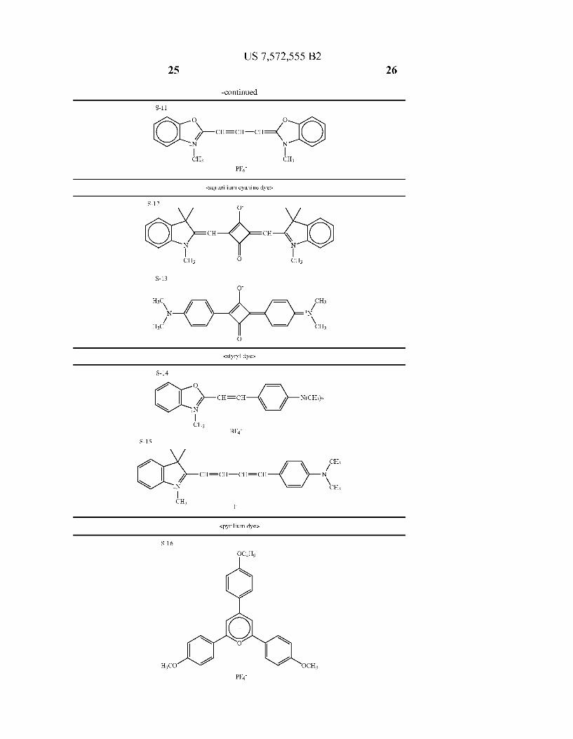
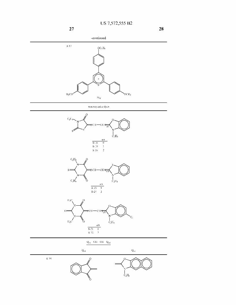
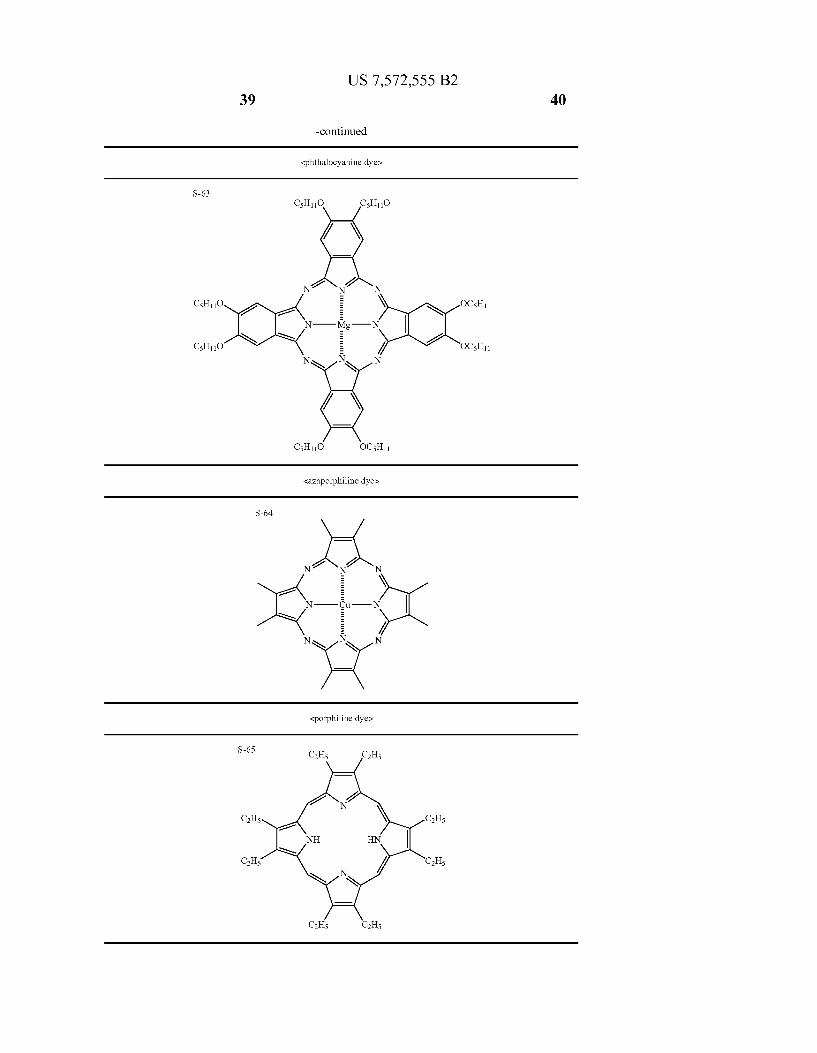
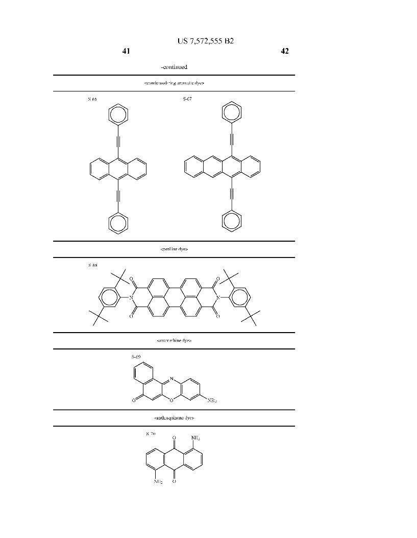
dye, a squarilium cyanine dye, a styryl dye, a pyrilium dye, a merocyanine dye, an arylidene dye, an oxonol dye, an aZule nium dye, a coumarin dye, a ketocoumarin dye, a styrylcou marin dye, a pyran dye, a Xanthene dye, a thioxanthene dye, a phenothiazine dye, a phenoxazine dye, a phenazine dye, a phthalocyanine dye, an azaporphiline dye, a porphiline dye, a condensed-ring aromatic dye, a perylene dye, an azomethine dye, an anthraquinone dye, a metal complex dye, or a metal locene dye, more preferably a cyanine dye, a squarilium cyanine dye, a pyrilium dye, a merocyanine dye, an oxonol dye, a coumarin dye, a ketocoumarin dye, a styrylcoumarin dye, a pyran dye, a Xanthene dye, a thioxanthene dye, a condensed-ring aromatic dye, a metal complex dye, or a metallocene dye, and further preferably a cyanine dye, a merocyanine dye, an oxonol dye, a metal complex dye, or a metallocene dye. The metal complex dye is particularly pref erably a Ru complex dye, and the metallocene dye is particu larly preferably a ferrocene.
Also dyes described in “Dye Handbook” (Shinya Ogawara, Kodan-sha, 1986), “Chemistry of Functional Dyes' (Shinya Ogawara, CMC, 1981), and “Special Functional Materials” (Chuzaburo Ikemori et al., CMC, 1986) may be employed as the sensitizing dye of the invention. The sensitizing dye of the invention is not limited to Such examples but can be any dye showing an absorption to the light in the visible region. Such sensitizing dye may be selected so as to match the wavelength of the laser employed as the light Source according to the purpose of use, and, depending on the purpose, two or more sensitizing dyes may be employed in combination. The sensitizing dye to be employed in the hologram record
ing material of the invention is more preferably a Ru complex dye, a ferrocene derivative, a cyanine dye or a merocyanine dye.
Preferred examples of the Ru complex dye and the fer rocene derivative are those described in Japanese Patent Application No. 2004-91983. The sensitizing dye to be employed in the invention is
further preferably a cyanine dye or a merocyanine dye. Also in the case the sensitizing dye of the invention is a
cyanine dye, it preferably is a cyanine dye having a benzox azole ring, a benzothiazole ring, a benzimidazole ring, an indolenine ring, or a quinoline ring (preferred examples to be shown later), more preferably a cyanine dye having a benzox azole ring, a benzothiazole ring, or a benzimidazole ring, and most preferably a cyanine ring having a benzoxazole ring. The cyanine dye preferred in the invention is represented
by formula (1):
7 7.
6 O O 6
IOC) to cro- O (R3)a3 Nt N (R4)a4 4 4.
Cly R R
In the invention, when a specified portion is called a 'group', it means that such group may be substituted with one or more (up to maximum possible) Substituents or may not be substituted, unless specified otherwise. For example an “alkyl group” means a Substituted or non-substituted alkyl group. Also a substituent employable in the compound of the inven tion may be any Substituent.
Also in the invention, when a specified portion is called a “ring', or in the case a “ring is included in a 'group'. Such
US 7,572,555 B2 19
ring may be a single ring or condensed rings unless specified otherwise, and may be substituted or non-substituted.
For example, an “aryl group” may be a phenyl group or a naphthyl group, or a Substituted phenyl group.
In the formula (1), R and R2 each independently repre sents an alkyl group (preferably with 1-20 carbon atoms (hereinafter represented as C number) such as methyl, ethyl, n-propyl, isopropyl. n-butyl, n-pentyl, benzyl, 3-sulfopropyl. 4-sulfobutyl, 3-methyl-3-sulfopropyl. 2'-sulfobenzyl, car boxymethyl, or 5-carboxypentyl), an alkenyl group (prefer ably with C number of 2-20 such as vinyl, allyl, or 1,3- butadienyl), an alkynyl group (preferably with C number of 2-20. Such as 2-propinyl, or 1,3-butadiinyl), or a cycloalkyl group (preferably with C number of 3-20, such as cyclopro pyl, cyclopentyl or cyclohexyl), and more preferably an alkyl group. R and R may be mutually same or different, but prefer
ably mutually same. In the formula (1), R and R each independently repre
sents a Substituent, and preferred examples of the Substituent include an alkyl group (preferably with C number of 1-20, Such as methyl, ethyl, n-propyl, isopropyl. n-butyl, n-pentyl, benzyl, 3-sulfopropyl, 4-sulfobutyl, carboxymethyl, or 5-car boxypentyl), an alkenyl group (preferably with C number of 2-20, such as vinyl, allyl, 2-butenyl or 3-butadienyl), a cycloalkyl group (preferably with C number of 3-20, such as cyclopentyl or cyclohexyl), an aryl group (preferably with C number of 6-20, such as phenyl, 2-chlorophenyl, 4-methox yphenyl, 3-methylphenyl or 1-naphthyl), a heterocyclic group (preferably with C number of 1-20, such as pyridyl, thienyl, furyl, thiazolyl, imidazolyl, pyrazolyl pyrrolidino, piperidino or morpholino), an alkynyl group (preferably with C number of 2-20, such as ethinyl, 2-propinyl, 1,3-butadunyl or 2-phenylethinyl), a halogenatom (such as F. Cl, Br or I), an amino group (preferably with C number of 0-20 including an alkylamino, an arylamino or a heterocyclic amino, Such as amino, dimethylamino, diethylamino, dibutylamino or anilino), a cyano group, a nitro group, a hydroxyl group, a mercapto group, a carboxyl group, a Sulfo group, a phospho nic acid group, an acyl group (preferably with C number of 1-20. Such as acetyl, benzoyl, salicyloyl or pivaloyl), an alkoxy group (preferably with C number of 1-20, such as methoxy, butoxy or cyclohexyloxy), an aryloxy group (pref erably with C number of 6-26, such as phenoxy or 1-naph thoxy), an alkylthio group (preferably with Cnumber of 1-20, Such as methylthio, or ethylthio), an arylthio group (prefer ably with C number of 6-20, such as phenylthio or 4-chlo rophenylthio), an alkylsulfonyl group (preferably with C number of 1-20, such as methanesulfonyl or butanesulfonyl), an arylsulfonyl group (preferably with C number of 6-20, Such as benzenesulfonyl or paratoluenesulfonyl), a Sulfamoyl group (preferably with C number of 0-20, such as sulfamoyl, N-methylsulfamoyl or N-phenylsulfamoyl), a carbamoyl group (preferably with C number of 1-20, such as carbamoyl, N-methylcarbamoyl N,N-dimethylcarbamoyl or N-phenyl carbamoyl), an acylamino group (preferably with C number of 1-20. Such as acetylamino or benzoylamino), an imino group (preferably with C number of 2-20, such as phthal imino), an acyloxy group (preferably with C number of 1-20, Such as acetyloxy, or benzoyloxy), an alkoxycarbonyl group (preferably with C number of 2-20, such as methoxycarbonyl or phenoxycarbonyl), and a carbamoylamino group (prefer ably with Cnumber of 1-20, such as carbamoylamino, N-me thylcarbamoylamino or N-phenylcarbamoylamino), more preferably an alkyl group, an aryl group, a heterocyclic group, a halogen atom, a cyano group, a carboxyl group, a Sulfo group, an alkoxy group, a sulfamoyl group, a carbamoyl
10
15
25
30
35
40
45
50
55
60
65
20 group and analkoxycarbonyl group, and further preferably an alkyl group, an aryl group, an alkoxy group, a halogen atom, a Sulfamoyl group, an alkoxycarbonyl group, a carbamoyl group and a cyano group.
In the formula (1), a3 and a4 each independently represents an integer of 0-4, more preferably each independently repre sents an integer of 0-2, and further preferably represents 0 or 1. Also in the case of a hologram recording wavelength of 532 nm, both a3 and a4 represent 0.
a3 and a4 may be mutually same or different, but are preferably same.
In the case a3 and a4 each is 1 or larger, it is preferable that R is substituted in 5-position or 6-position and R is Substi tuted in 5'-position or 6'-position, and more preferably that R. is substituted in 5-position and R is substituted in 5'-position.
In the case a3 or a4 is 2 or larger, plural RS or RS may be mutually same or different or may be mutually bonded to form a ring, which is preferably a benzene ring, a naphthalene ring, a thiophene ring, a furan ring, a benzofuran ring, a pyrrole ring, an indole ring, an imidazole ring, a pyrazol ring, a cyclohexene ring, a dioxaene ring or a pyridine ring.
In the formula (1), Rs. R and R, each independently rep resents a hydrogen atom or a substituent (preferred examples thereof being same as those shown for Rs), and more prefer ably a hydrogenatom, an alkyl group, a halogenatom, a nitro group, an alkoxy group, an aryl group, a nitro group, a het erocyclic group, an aryloxy group, an acylamino group, a carbamoyl group, a Sulfo group, a hydroxyl group, a carboxyl group, an alkylthio group, or a cyano group, further prefer ably a hydrogen atom or an alkyl group, and most preferably a hydrogen atom, a methyl group or an ethyl group.
Rs. Re and R, may be mutually bonded to form a ring, which is preferably a cyclolhexene ring, a cyclopentene ring, a benzene ring, or a thiophene group.
In the formula (1), n1 represents an integer of 0 to 2, more preferably 0 or 1.
In the case of a hologram recording wavelength of 532 nm, n1 is preferably 1, and more preferably n1 is 1 and both a3 and a4 represent 0.
Also in the case of a hologram recording wavelength of 405-415 nm, n1 is more preferably 0.
In the formula (1), CI represents a charge neutralizing ion, which can preferably be, as an anion, PF, BF, SbF. B(CHs), CFSO, CFSO, CHSO, 4-CHCHSO, CHSO, CHOSO, CHCOO, CFCOO, CIO, I, Br, Cl, FT or OH, or as a cation, H", Li", K", Cs", Mg, Ca", "HN(CH), N(CH) “N(C Ho), CHNH, CHN CHs or the like.
In the formula (1), y represents a number required for neutralizing the charge.
Then, in the case the sensitizing dye of the invention is a merocyanine dye, it preferably has, as a basic nucleus, a benzoxazole ring, a benzothiazole ring, a benzoimidazole ring, a quinoline ring, or a benzene ring Substituted with an amino group or an alkoxy group, and, as an acidic nucleus, 2-pyrazolon-5-one, pyrazolidine-3,5-dione, rhodanine, indane-1,3-dion, thiophen-3-one, thiophen-3-one-1,1-diox ide, 1,3-dioxane-4,6-dione, barbituric acid, 2-thiobarbituric acid, isooxazolone, coumarin-2,4-ione, ethyl cyanoacetate, methylcyanoacetate, malononitrile or a derivative thereof.
In particular, it more preferably has, as an acidic nucleus, pyrazolidine-3,5-dione, rhodanine, indane-1,3-dion, 1.3-ioX ane-4,6-dione, barbituric acid, or 2-thiobarbituric acid, and further preferably barbituric acid, or 2-thiobarbituric acid. A merocyanine dye preferred in the invention is repre
sented by formula (2):
US 7,572,555 B2 21
R11 O V 7 N X2 6
X=( CR-CR.K Ol, N N R!) / 4 al4
R12 O 13
In the formula (2), X represents O or S. In the formula (2), X represents —O— —S ,
—NR7—, or—CRR : R and Reachindependently represents a hydrogenatom, an alkyl group, an alkenyl group, an alkynyl group, a cycloalkyl group, an aryl group or a heterocyclic group (preferred examples thereof being same as those shown for R or Rs), more preferably a hydrogenatom, an alkyl group or an aryl group and further preferably an alkyl group. R7, Rs and Ro each independently represents an alkyl
group, an alkenyl group, an alkynyl group, a cycloalkyl group, an aryl group or a heterocyclic group (preferred examples thereof being same as those shown for R or Rs), more preferably an alkyl group or an aryl group, and further preferably a alkyl group. Rs and R may be mutually bonded to form a ring, which
can preferably be a cyclohexane ring or a cyclopentane ring. In the formula (2), R represents an alkyl group, analkenyl
group, an alkynyl group, or a cycloalkyl group (preferred examples thereof being same as those shown for R), more preferably an alkyl group.
S-1
S-2
10
15
25
30
22 In the formula (2), R represents a Substituent (preferred
examples thereof being same as those shown for Rs), more preferably an alkyl group, an aryl group, an alkoxy group, a halogenatom, a sulfamoyl group, an alkoxycarbonyl group, a carbamoyl group or a cyano group.
In the formula (2), a14 represents an integer of 0 to 4, more preferably 0 to 2 and further preferably 0 or 1.
In the case a14 is 1 or larger, R is more preferably Sub stituted in 5-position or 6-position, and further preferably in 5-position.
In the case a14 is 2 or larger, plural Ras may be mutually same or different, or may be mutually bonded to form a ring, which can preferably be a benzene ring, a naphthalene ring, a thiophene ring, afuran ring, a benzofuran ring, a pyrrole ring, an indole ring, an imidazole ring, a pyrazole ring, a cyclohex enering, a dioxaene ring or a pyridine ring.
In the formula (2), Rs and Reach independently repre sents a hydrogen atom or a substituent (preferred examples thereof being same as those shown for Rs), more preferably a hydrogen atom or an alkyl group, and further preferably a hydrogen atom, a methyl group or an ethyl group. Rs and R may be mutually bonded to form a ring, which
can preferably be a cyclohexene ring, a cyclopentene ring, a benzene ring, a thiophene ring or the like.
In the formula (2), n2 represents an integer of 0 to 2, more preferably 0 or 1, n1 is preferably 1 in the case of a hologram recording wavelength of 532 nm, and more preferably 0 in the case of a hologram recording wavelength of 405-415 nm.
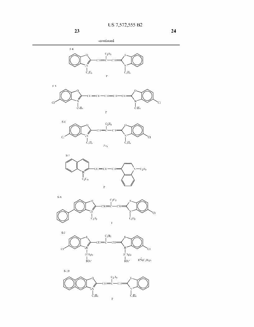
In the following, specific examples of the sensitizing dye of the invention will be shown, but the present invention is not limited to Such examples.
<cyanine dyes
O O
X-CH= -CH={ N
C2H5 CH5 I
S S
X-CH={ C
C2H5 C2H5 I
S-3
H3C H3C CH3 CH
2-CH=CH-CH N N
CH5 CH5 BF4
US 7,572,555 B2 29 30
-continued
S-26 O O
- O 7\ st / \,
S-28 -CIO
X -CO S-30
O
co-C-5-)-cal CH3 H3C
S-31 O
co-O-----e. S-32
O
H3CO
CH N
S-33
O
N city- N

US 7,572,555 B2 41 42
-continued
<condensed-ring aromatic dye
S-66 S-67
<periline dye
O S O N ( ) ( ) N O O
<azomethine dye
S-69
N
21 Ol O O NEt
<anthraquinone dyes
S-68
S-70 O NH2


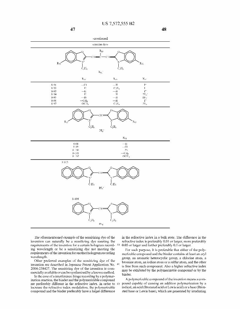
US 7,572,555 B2 47
-continued
<cyanine dye
48
O O
X-CH= -CH={ R52 R52
Rs
CH5 CH5 PF
S-98 S-99 S-100 S-101 S-102
S-103
O
C2H5 C2H5 PF
S-104
The aforementioned example of the sensitizing dye of the invention can naturally be a sensitizing dye meeting the requirements of the invention for a certain hologram record ing wavelength or be a sensitizing dye not meeting the requirements of the invention for anotherhologram recording wavelength.
Other preferred examples of the sensitizing dye of the invention are described in Japanese Patent Application No. 2004-238427. The sensitizing dye of the invention is com mercially available or can be synthesized by a known method.
In the case of a interference fringe recording by a polymer ization reaction, the binder and the polymerizable compound are preferably different in the refractive index. In order to increase the refractive index modulation, the polymerizable compound and the binder preferably have a larger difference
55
60
65
—OCH
in the refractive index in a bulk state. The difference in the refractive index is preferably 0.01 or larger, more preferably 0.05 or larger and further preferably 0.1 or larger.
For such purpose, it is preferable that either of the poly merizable compound and the binder contains at least an aryl group, an aromatic heterocyclic group, a chlorine atom, a bromine atom, an iodine atom or a Sulfur atom, and the other is free from Such component. Also a higher refractive index may be exhibited by the polymerizable compound or by the binder.
A polymerizable compound of the invention means a com pound capable of causing an addition polymerization by a radical, an acid (Bronsted acid or Lewis acid) or a base (Bron sted base or Lewis base), which are generated by irradiating
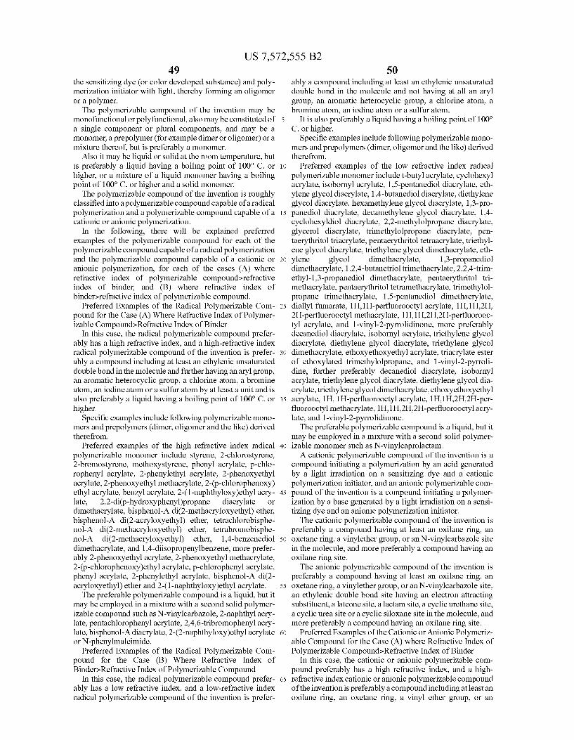
US 7,572,555 B2 49
the sensitizing dye (or color developed Substance) and poly merization initiator with light, thereby forming an oligomer or a polymer. The polymerizable compound of the invention may be
monofunctional or polyfunctional, also may be constituted of a single component or plural components, and may be a monomer, a prepolymer (for example dimer or oligomer) or a mixture thereof, but is preferably a monomer.
Also it may be liquid or solid at the room temperature, but is preferably a liquid having a boiling point of 100° C. or higher, or a mixture of a liquid monomer having a boiling point of 100° C. or higher and a solid monomer. The polymerizable compound of the invention is roughly
classified into a polymerizable compound capable of a radical polymerization and a polymerizable compound capable of a cationic or anionic polymerization.
In the following, there will be explained preferred examples of the polymerizable compound for each of the polymerizable compound capable of a radical polymerization and the polymerizable compound capable of a cationic or anionic polymerization, for each of the cases (A) where refractive index of polymerizable compound>refractive index of binder, and (B) where refractive index of binder-refractive index of polymerizable compound.
Preferred Examples of the Radical Polymerizable Com pound for the Case (A) Where Refractive Index of Polymer izable Compound>Refractive Index of Binder
In this case, the radical polymerizable compound prefer ably has a high refractive index, and a high-refractive index radical polymerizable compound of the invention is prefer ably a compound including at least an ethylenic unsaturated double bond in the molecule and further having an aryl group, an aromatic heterocyclic group, a chlorine atom, a bromine atom, an iodine atom or a Sulfur atom by at least a unit and is also preferably a liquid having a boiling point of 100° C. or higher.
Specific examples include following polymerizable mono mers and prepolymers (dimer, oligomer and the like) derived therefrom.
Preferred examples of the high refractive index radical polymerizable monomer include styrene, 2-chlorostyrene, 2-bromostyrene, methoxystyrene, phenyl acrylate, p-chlo rophenyl acrylate, 2-phenylethyl acrylate, 2-phenoxyethyl acrylate, 2-phenoxyethyl methacrylate, 2-(p-chlorophenoxy) ethyl acrylate, benzyl acrylate, 2-(1-naphthyloxy)ethyl acry late, 2,2-di(p-hydroxyphenyl)propane diacrylate or dimethacrylate, bisphenol-A di(2-methacryloxyethyl) ether, bisphenol-A di(2-acryloxyethyl) ether, tetrachlorobisphe nol-A di(2-methacryloxyethyl) ether, tetrabromobisphe nol-A di(2-methacryloxyethyl) ether, 1,4-benzenediol dimethacrylate, and 1,4-diisopropenylbenzene, more prefer ably 2-phenoxyethyl acrylate, 2-phenoxyethyl methacrylate, 2-(p-chlorophenoxy)ethyl acrylate, p-chlorophenyl acrylate, phenyl acrylate, 2-phenylethyl acrylate, bisphenol-A di(2- acryloxyethyl) ether and 2-(1-naphthyloxy)ethyl acrylate. The preferable polymerizable compound is a liquid, but it
may be employed in a mixture with a second solid polymer izable compound Such as N-Vinylcarbazole, 2-naphthyl acry late, pentachlorophenyl acrylate, 2,4,6-tribromophenyl acry late, bisphenol-Adiacrylate, 2-(2-naphthyloxy)ethyl acrylate or N-phenylmaleimide.
Preferred Examples of the Radical Polymerizable Com pound for the Case (B) Where Refractive Index of Binder-Refractive Index of Polymerizable Compound
In this case, the radical polymerizable compound prefer ably has a low refractive index, and a low-refractive index radical polymerizable compound of the invention is prefer
5
10
15
25
30
35
40
45
50
55
60
65
50 ably a compound including at least an ethylenic unsaturated double bond in the molecule and not having at all an aryl group, an aromatic heterocyclic group, a chlorine atom, a bromine atom, an iodine atom or a Sulfur atom.
It is also preferably a liquid having a boiling point of 100° C. or higher.
Specific examples include following polymerizable mono mers and prepolymers (dimer, oligomer and the like) derived therefrom.
Preferred examples of the low refractive index radical polymerizable monomer include t-butyl acrylate, cyclohexyl acrylate, isobornyl acrylate, 1,5-pentanediol diacrylate, eth ylene glycol diacrylate, 1,4-butanediol diacrylate, diethylene glycol diacrylate, hexamethylene glycol diacrylate, 1,3-pro panediol diacrylate, decamethylene glycol diacrylate, 1,4- cyclohexyldiol diacrylate, 2.2-methylolpropane diacrylate, glycerol diacrylate, trimethylolpropane diacrylate, pen taerythritol triacrylate, pentaerythritol tetraacrylate, triethyl ene glycol diacrylate, triethylene glycol dimethacrylate, eth ylene glycol dimethacrylate, 1,3-propanediol dimethacrylate, 1,2,4-butanetriol trimethacrylate, 2.2,4-trim ethyl-1,3-propanediol dimethacrylate, pentaerythritol tri methacrylate, pentaerythritol tetramethacrylate, trimethylol propane trimethacrylate, 1.5-pentanediol dimethacrylate, diallyl fumarate, 1H, 1 H-perfluorooctyl acrylate, 1H, 1H,2H, 2H-perfluorooctyl methacrylate, 1H, 1H,2H2H-perfluorooc tyl acrylate, and 1-vinyl-2-pyrrolidinone, more preferably decanediol diacrylate, isobornyl acrylate, triethylene glycol diacrylate, diethylene glycol diacrylate, triethylene glycol dimethacrylate, ethoxyethoxyethyl acrylate, triacrylate ester of ethoxylated trimethylolpropane, and 1-vinyl-2-pyrroli dine, further preferably decanediol diacrylate, isobornyl acrylate, triethylene glycol diacrylate, diethylene glycol dia crylate, triethylene glycol dimethacrylate, ethoxyethoxyethyl acrylate, 1H, 1 H-perfluorooctyl acrylate, 1H, 1H,2H2H-per fluorooctyl methacrylate, 1H, 1H,2H.2H-perfluorooctyl acry late, and 1-vinyl-2-pyrrolidinone. The preferable polymerizable compound is a liquid, but it
may be employed in a mixture with a second solid polymer izable monomer Such as N-Vinylcaprolactam. A cationic polymerizable compound of the invention is a
compound initiating a polymerization by an acid generated by a light irradiation on a sensitizing dye and a cationic polymerization initiator, and an anionic polymerizable com pound of the invention is a compound initiating a polymer ization by a base generated by a light irradiation on a sensi tizing dye and an anionic polymerization initiator. The cationic polymerizable compound of the invention is
preferably a compound having at least an OXilane ring, an oxetane ring, a vinylether group, or an N-vinylcarbazole site in the molecule, and more preferably a compound having an oXilane ring site. The anionic polymerizable compound of the invention is
preferably a compound having at least an OXilane ring, an oxetane ring, a vinylether group, oran N-vinylcarbazole site, an ethylenic double bond site having an electron attracting Substituent, a latcone site, a lactam site, a cyclic urethane site, a cyclic urea site or a cyclic siloxane site in the molecule, and more preferably a compound having an oxilane ring site.
Preferred Examples of the Cationic or Anionic Polymeriz able Compound for the Case (A) where Refractive Index of Polymerizable Compound>Refractive Index of Binder
In this case, the cationic or anionic polymerizable com pound preferably has a high refractive index, and a high refractive index cationic oranionic polymerizable compound of the invention is preferably a compound including at least an oXilane ring, an oxetane ring, a vinyl ether group, or an
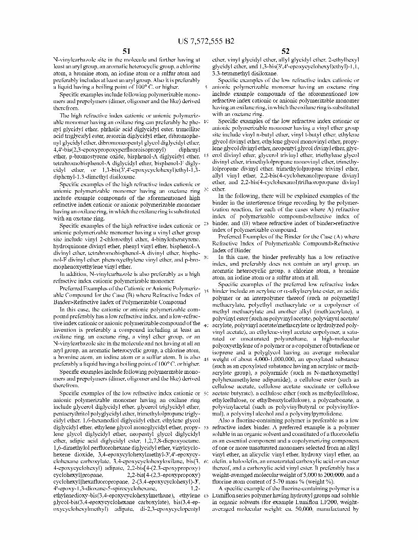
US 7,572,555 B2 51
N-vinylcarbazole site in the molecule and further having at least an aryl group, an aromatic heterocyclic group, a chlorine atom, a bromine atom, an iodine atom or a sulfur atom and preferably includes at least an aryl group. Also it is preferably a liquid having a boiling point of 100° C. or higher.
Specific examples include following polymerizable mono mers and prepolymers (dimer, oligomer and the like) derived therefrom.
The high refractive index cationic or anionic polymeriz able monomer having an oxilane ring can preferably be phe nyl glycidyl ether, phthalic acid diglycidyl ester, trimellitic acid triglycidyl ester, resorcin diglycidyl ether, dibromophe nylglycidyl ether, dibromoneopentylglycol diglycidyl ether, 4,4'-bis(2,3-epoxypropoxyperfluoroisopropyl) diphenyl ether, p-bromostyrene oxide, bisphenol-A diglycidyl ether, tetrabromobisphenol-A diglycidyl ether, bisphenol-F digly cidyl ether, or 1,3-bis(3',4'-epoxycyclohexyl)ethyl-1,3- diphenyl-1,3-dimethyl disiloxane.
Specific examples of the high refractive index cationic or anionic polymerizable monomer having an oxetane ring include example compounds of the aforementioned high refractive index cationic or anionic polymerizable monomer having an oxilane ring, in which the oxilane ring is substituted with an oxetane ring.
Specific examples of the high refractive index cationic or anionic polymerizable monomer having a vinyl ether group site include vinyl 2-chloroethyl ether, 4-binyletherstyrene, hydroquinone divinyl ether, phenyl vinyl ether, bisphenol-A divinyl ether, tetrabromobisphenol-A divinyl ether, bisphe nol-F divinyl ether, phenoxyethylene vinyl ether, and p-bro mophenoxyethylene vinyl ether.
In addition, N-vinylcarbazole is also preferably as a high refractive index cationic polymerizable monomer.
Preferred Examples of the Cationic or Anionic Polymeriz able Compound for the Case (B) where Refractive Index of Binder-Refractive Index of Polymerizable Compound
In this case, the cationic or anionic polymerizable com pound preferably has a low refractive index, and a low-refrac tive index cationic oranionic polymerizable compound of the invention is preferably a compound including at least an oXilane ring, an oxetane ring, a vinyl ether group, or an N-vinylcarbazole site in the molecule and not having at all an aryl group, an aromatic heterocyclic group, a chlorine atom, a bromine atom, an iodine atom or a Sulfur atom. It is also preferably a liquid having a boiling point of 100° C. or higher.
Specific examples include following polymerizable mono mers and prepolymers (dimer, oligomer and the like) derived therefrom.
Specific examples of the low refractive index cationic or anionic polymerizable monomer having an oxilane ring include glycerol diglycidyl ether, glycerol triglycidyl ether, pentaerythritol polyglycidyl ether, trimethylolpropane trigly cidyl ether, 1.6-hexanediol diglycidyl ether, ethylene glycol diglycidyl ether, ethylene glycol monoglycidyl ether, propy lene glycol diglycidyl ether, neopentyl glycol diglycidyl ether, adipic acid diglycidyl ester, 1,2,7,8-diepoxyoctane, 1,6-dimethylol perfluorohexane diglycidyl ether, vinylcyclo hexene dioxide, 3,4-epoxycylohexylmethyl-3',4'-epoxycy clohexane carboxylate, 3,4-epoxycyclohexyloxilane, bis(3, 4-epoxycyclohexyl) adipate, 2.2-bis(4-(2,3-epoxypropoxy) cyclohexylpropane, 2.2-bis(4-(2,3-epoxypropoxy) cyclohexylhexafluoropropane, 2-(3.4-epoxycyclohexyl)-3', 4'-epoxy-1,3-dioxane-5-spirocyclohexane, 1.2- ethylenedioxy-bis(3,4-epoxycyclohexylmethane), ethylene glycol-bis(3,4-epoxycyclohexane carboxylate), bis(3,4-ep oxycyclohexylmethyl) adipate, di-2,3-epoxycyclopentyl
5
10
15
25
35
40
45
50
55
60
65
52 ether, vinyl glycidyl ether, allyl glycidyl ether, 2-ethylhexyl glycidyl ether, and 1,3-bis(3',4'-epoxycyclohexyl)ethyl)-1,1, 3,3-tetramethyl disiloxane.
Specific examples of the low refractive index cationic or anionic polymerizable monomer having an oxetane ring include example compounds of the aforementioned low refractive index cationic or anionic polymerizable monomer having an oxilane ring, in which the oxilane ring is substituted with an oxetane ring.
Specific examples of the low refractive index cationic or anionic polymerizable monomer having a vinyl ether group site include vinyl n-butyl ether, vinyl t-butyl ether, ethylene glycol divinyl ether, ethylene glycol monovinyl ether, propy lene glycol divinyl ether, neopentylglycol divinyl ether, glyc erol divinyl ether, glycerol trivinyl ether, triethylene glycol divinyl ether, trimethylolpropane monovinyl ether, trimethy lolpropane divinyl ether, trimethylolpropane trivinyl ether, allyl vinyl ether, 2.2-bis(4-cyclohexanol)propane divinyl ether, and 2.2-bis(4-cyclohexanol)trifluoropropane divinyl ether.
In the following, there will be explained examples of the binder in the interference fringe recording by the polymer ization reaction, for each of the cases where A) refractive index of polymerizable compound>refractive index of binder, and (B) where refractive index of binders refractive index of polymerizable compound.
Preferred Examples of the Binder for the Case (A) where Refractive Index of Polymerizable Compound>Refractive Index of Binder
In this case, the binder preferably has a low refractive index, and preferably does not contain an aryl group, an aromatic heterocyclic group, a chlorine atom, a bromine atom, an iodine atom or a Sulfur atom at all.
Specific examples of the preferred low refractive index binder include an acrylate or C-alkylacrylate ester, an acidic polymer or an interpolymer thereof (such as polymethyl methacrylate, polyethyl methacrylate or a copolymer of methyl methacrylate and another alkyl (meth)acrylate), a polyvinyl ester (Such as polyvinyl acetate, polyvinyul acetate/ acrylate, polyvinyl acetate/methacrylate or hydrolyzed poly vinyl acetate), an ethylene-vinyl acetate copolymer, a satu rated or unsaturated polyurethane, a high-molecular polyoxyethylene of a polymer oracopolymer ofbutadiene or isoprene and a polyglycol having an average molecular weight of about 4,000-1,000,000, an epoxylated substance (such as an epoxylated Substance having an acrylate or meth acrylate group), a polyarmide (Such as N-methoxymethyl polyhexamethylene adipamide), a cellulose ester (such as cellulose acetate, cellulose acetate Succinate or cellulose acetate butyrate), a cellulose ether (Such as methylcellulose, ethylcellulose, or ethylbenzylcellulose), a polycarbonate, a polyvinylacetal (such as polyvinylbutyral or polyvinylfor mal), a polyvinyl alcohol and a polyvinylpyrrolidone.
Also a fluorine-containing polymer is preferable as a low refractive index binder. A preferred example is a polymer soluble in an organic solvent and constituted of a fluoroolefin as an essential component and a copolymerizing component of one or more unsaturated monomers selected from an alkyl vinyl ether, an alicyclic vinyl ether, hydroxy vinyl ether, an olefin, a haloolefin, an unsaturated carboxylic acid or an ester thereof, and a carboxylic acid vinyl ester. It preferably has a weight-averaged molecular weight of 5,000 to 200,000, and a fluorine atom content of 5-70 mass % (weight%). A specific example of the fluorine-containing polymer is a
Lumiflon series polymer having hydroxyl groups and soluble in organic solvents (for example Lumiflon LF200, weight averaged molecular weight: ca. 50,000, manufactured by
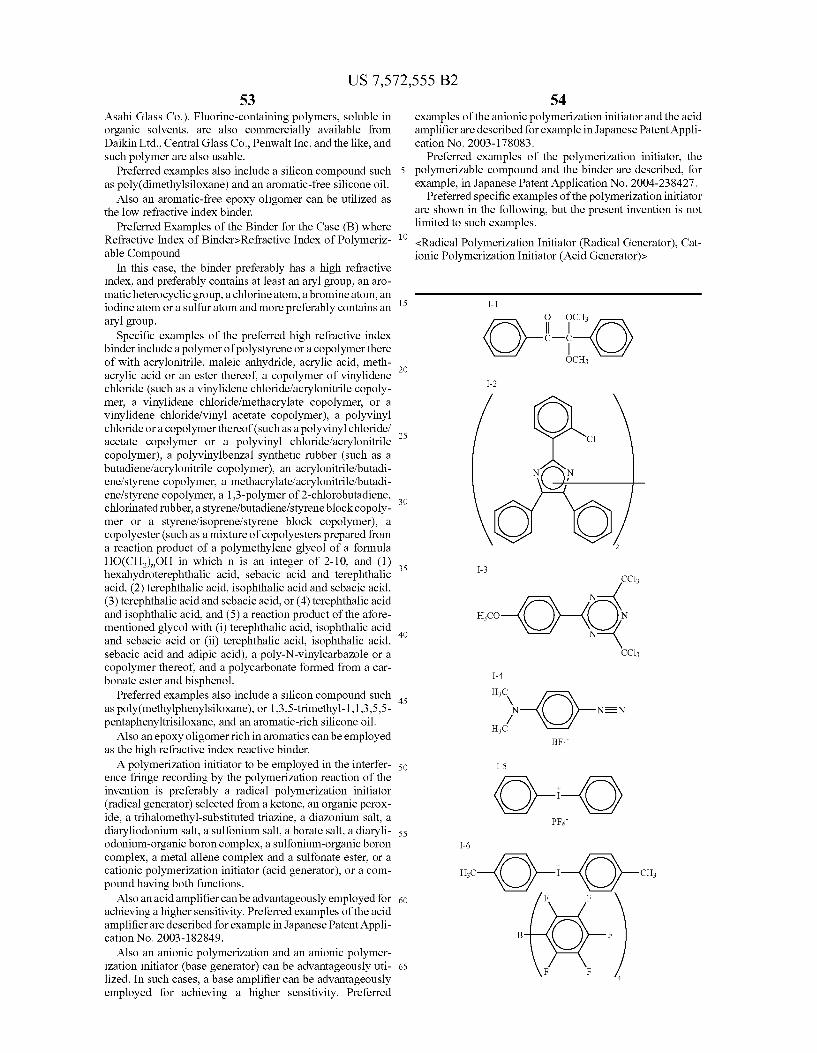
US 7,572,555 B2 53
Asahi Glass Co.). Fluorine-containing polymers, soluble in organic solvents, are also commercially available from Daikin Ltd., Central Glass Co., Penwalt Inc. and the like, and Such polymer are also usable.
Preferred examples also include a silicon compound Such as poly(dimethylsiloxane) and an aromatic-free silicone oil.
Also an aromatic-free epoxy oligomer can be utilized as the low refractive index binder.
Preferred Examples of the Binder for the Case (B) where Refractive Index of Binder-Refractive Index of Polymeriz able Compound
In this case, the binder preferably has a high refractive index, and preferably contains at least an aryl group, an aro matic heterocyclic group, a chlorine atom, a bromine atom, an iodine atom or a Sulfur atom and more preferably contains an aryl group.
Specific examples of the preferred high refractive index binder include a polymer of polystyrene or a copolymer there of with acrylonitrile, maleic anhydride, acrylic acid, meth acrylic acid or an ester thereof, a copolymer of vinylidene chloride (such as a vinylidene chloride/acrylonitrile copoly mer, a vinylidene chloride/methacrylate copolymer, or a vinylidene chloride/vinyl acetate copolymer), a polyvinyl chloride or a copolymer thereof (such as a polyvinyl chloride/ acetate copolymer or a polyvinyl chloride? acrylonitrile copolymer), a polyvinylbenzal synthetic rubber (such as a butadiene/acrylonitrile copolymer), an acrylonitrile/butadi ene?styrene copolymer, a methacrylate/acrylonitrile/butadi ene?styrene copolymer, a 1.3-polymer of 2-chlorobutadiene, chlorinated rubber, a styrene/butadiene/styrene block copoly mer or a styrenefisoprene/styrene block copolymer), a copolyester (such as a mixture of copolyesters prepared from a reaction product of a polymethylene glycol of a formula HO(CH), OH in which n is an integer of 2-10, and (1) hexahydroterephthalic acid, sebacic acid and terephthalic acid, (2) terephthalic acid, isophthalic acid and sebacic acid, (3) terephthalic acid and sebacic acid, or (4) terephthalic acid and isophthalic acid, and (5) a reaction product of the afore mentioned glycol with (i) terephthalic acid, isophthalic acid and sebacic acid or (ii) terephthalic acid, isophthalic acid, sebacic acid and adipic acid), a poly-N-vinylcarbazole or a copolymer thereof, and a polycarbonate formed from a car bonate ester and bisphenol.
Preferred examples also include a silicon compound Such as poly(methylphenylsiloxane), or 1,3,5-trimethyl-1,1,3,5,5- pentaphenyltrisiloxane, and an aromatic-rich silicone oil.
Also an epoxy oligomer rich in aromatics can be employed as the high refractive index reactive binder. A polymerization initiator to be employed in the interfer
ence fringe recording by the polymerization reaction of the invention is preferably a radical polymerization initiator (radical generator) selected from a ketone, an organic peroX ide, a trihalomethyl-substituted triazine, a diazonium salt, a diaryliodonium salt, a Sulfonium salt, aborate salt, a diaryli odonium-organic boron complex, a Sulfonium-organic boron complex, a metal allene complex and a sulfonate ester, or a cationic polymerization initiator (acid generator), or a com pound having both functions.
Also an acid amplifier can be advantageously employed for achieving a higher sensitivity. Preferred examples of the acid amplifier are described for example in Japanese Patent Appli cation No. 2003-182849.
Also an anionic polymerization and an anionic polymer ization initiator (base generator) can be advantageously uti lized. In Such cases, a base amplifier can be advantageously employed for achieving a higher sensitivity. Preferred
5
10
15
25
30
35
40
45
50
55
60
65
54 examples of the anionic polymerization initiator and the acid amplifier are described for example in Japanese Patent Appli cation No. 2003-178083.
Preferred examples of the polymerization initiator, the polymerizable compound and the binder are described, for example, in Japanese Patent Application No. 2004-238427.
Preferred specific examples of the polymerization initiator are shown in the following, but the present invention is not limited to Such examples. <Radical Polymerization Initiator (Radical Generator), Cat ionic Polymerization Initiator (Acid Generator)>
O it. I-1
c OCH
I-2
C
N N
2
I-3 CCl3
... Y. S. -O-O. CCl3
N
N
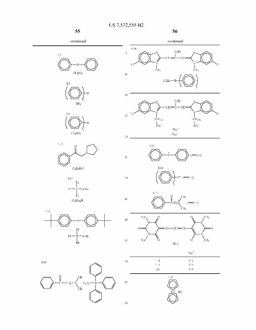
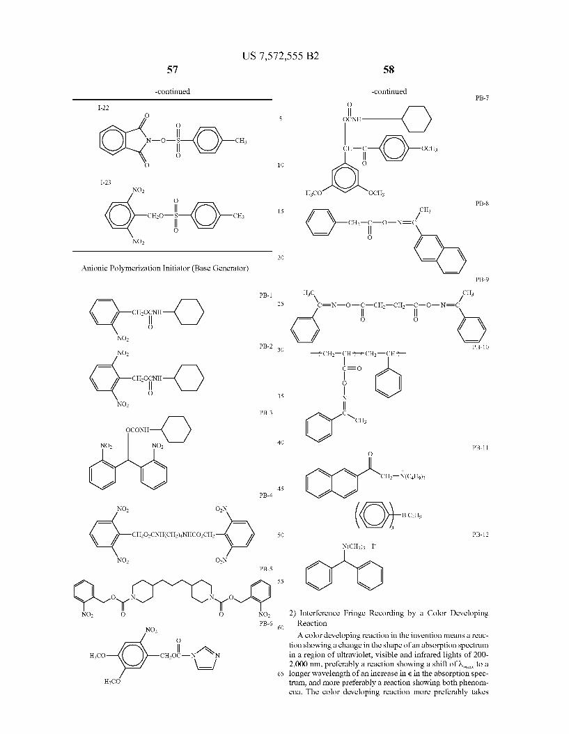
US 7,572,555 B2 57
-continued
I-22
O
O O I-23
O
cio- CH3 O w( )-N
O2
NO2
Anionic Polymerization Initiator (Base Generator)
PB-1
citri-O) O
NO PB-2
NO
cut-O) O
NO PB-3
NO NO
PB-4
NO ON
(-oil-) NO ON
PB-5
O Crc u? NO O O NO
PB-6 NO
O
| 1s HCO CHOC-N N
10
15
25
30
35
40
45
50
55
60
65
58
-continued PB-7
O
OCNH
CH-C OCH
O
HCO OCH PB-8
CH3 W
CH-C-O-N=C | O
PB-9
HC CH V M
c=n-o--cis-ch-i-o-n=c () O O
PB-10
-cis-pitch-i- CEO
O
N
| O YCH,
PB-11 O
--
CH-N(CHo).
BC4H9
3 PB-12
--
N(CH3)3 I
CrO 2) Interference Fringe Recording by a Color Developing
Reaction
A color developing reaction in the invention means a reac tion showing a change in the shape of an absorption spectrum in a region of ultraviolet, visible and infrared lights of 200 2,000 nm, preferably a reaction showing a shift of w to a longer wavelength of an increase in e in the absorption spec trum, and more preferably a reaction showing both phenom ena. The color developing reaction more preferably takes

US 7,572,555 B2 59
place within a wavelength region of 200-1,000 nm, and fur ther preferably within a wavelength region of 300-900 nm.
In the case the recording is performed by a color develop ing reaction, the hologram recording material of the invention preferably includes at least:
1) a sensitizing dye capable of absorbing light upon holo graphic exposure thereby generating an excited State; and
2) an interference fringe-recording component containing a dye precursor capable of forming a color developed Substance having an absorption shifted to a longer wave length than in an original state and having no absorption in a wavelength of a hologram reproducing light, and capable of recording interference fringes providing a refractive index modulation through a color develop ment by an electron or energy transfer from an excited state of the sensitizing dye or the color developed sub Stance.
A refractive index of a dye generally assumes a high value within a longer wavelength region starting from about a wavelength (W) of a linear absorption maximum, and assumes a very high value particularly in a region from W. to a wavelength longer than Wimax by about 200 nm, exceed ing 1.8 in certain dyes and also exceeding 2.0 in certain cases. On the other hand, non-dye organic compounds such as a binder polymer generally have a refractive index of about 1.4 to 1.6.
It will therefore be understood that a color development of the dye precursor by the holographic exposure is preferable not only for forming a difference in the absorbance but also for forming a large difference in the refractive index.
In the hologram recording material of the invention, the refractive index of the dye formed from the recording com ponents preferably becomes maximum in the vicinity of a wavelength of a laser to be employed for reproduction.
Preferred examples of the sensitizing dye are same as those described in the foregoing.
Preferred examples of the interference fringe-recording components include following combinations, of which pre ferred specific examples are shown in Japanese Patent Appli cation No. 2004-238.077.
i) A combination including at least an acid color-develop able dye precursor capable of color development with an acid, as a dye precursor, and an acid generator, the com bination if necessary further including an acid amplifier.
The acid generator is preferably a diaryliodonium salt, a Sulfonium salt, or a Sulfonate ester, and the acid generator (cationic polymerization initiator) mentioned above can be employed advantageously. A color developed Substance generated from the acid
color-developable dye precursor is preferably axanthene dye, a fluoran dye or a triphenylmethane dye. Particularly prefer able examples of the acid color-developable dye precursor are shown in the following, but the present invention is not lim ited to such examples.
L-1
10
15
25
30
35
40
45
50
55
60
65
CH3CONH
60
-continued L-2
L-3
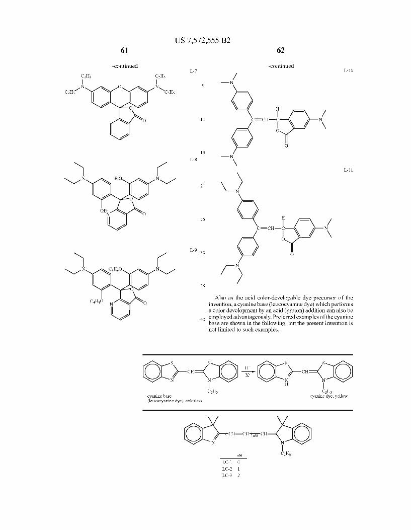
US 7,572,555 B2 61 62
-continued -continued L-7 L-10
-N N O N 5
CH-1 YC.H.,
O |
O 10 c=ch O
-N
( 15
N-N EtO N-1 2O \ ) N
25 H
2 t=ch- / \
O
L-9 O
/ ) Also as the acid color-developable dye precursor of the
invention, a cyanine base (leucocyanine dye) which performs a color development by an acid (proton) addition can also be employed advantageously. Preferred examples of the cyanine base are shown in the following, but the present invention is not limited to such examples.
40
S S S S H
CH Ho- CH / X M
cyanine base cyanine dye, yellow (leucocyanine dye), colorless
/ CH=CH-) is CH
nS6 CH5
LC-1 O
LC-2 1 LC-3 2
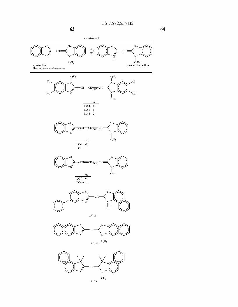

US 7,572,555 B2 65
-continued
--CIO t-O-CO CH5
cyanine base (leucocyanine dye), colorless
OO OC 2
N cit C2H5
LC-14
\ 3- N-CH LC-15
ii) A combination including at least a base color-develop able dye precursor, as a dye precursor, and a base gen erator, the combination if necessary further including a base amplifier.
The base generator is preferably the base generator (an ionic polymerization initiator) mentioned above, and the base color-developable dye precursor can be a non-dissociated Substance of a dissociable azo dye, a dissociable azomethine dye, a dissociable oxonol dye, a dissociable Xanthene dye, a dissociable fluoran dye, or a dissociable triphenylmethane dye.
Particularly preferable examples of the base color-devel opable dye precursor are shown in the following, but the present invention is not limited to Such examples.
C8H17 O O C8H17 V M N N
o={ CH-CH=CH-) \ )=0 N N
H3C O HO CH3
nél
DD-1 1 DD-2 2 DD-3 3
C4H9 O O C4H9 w M N N
s={ CH-CH=CH-) \ )=s N N
C4H9 O HO C4H9
nó
DD-4 O DD-5 1 DD-6 2
30
35
40
45
50
55
60
65
CH5 cyanine dye, yellow
66
-continued
O
CH-CH=CH-) O nél
DD-7 O DD-8 1 DD-9 2
CH-CH=CH-) N
nél
DD-10 O DD-11 1 DD-12 2
CH-CH=CH
DD-13 O DD-14 1
HO
HO
N
N
OH

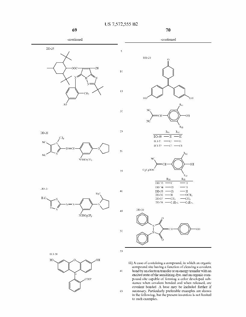
US 7,572,555 B2
-continued -continued
DD-25 5
DD-29 O
OOC-F-CN y 10 N2N1N
\ NF
15
HO OH
HO R51
2O NC
)=ch OH NC
R52 DD-26 25 R51 R52
CH DD-30 - H -H
NC W DD-31 - C -H N
DD-32 - C -Cl M NEN N
30 NC N R51
NHSOCF NC
)=CH OH
35 C2H5OOC
R52 R51 R52
DD-33 -H HH
DD-27 DD-34 - C -H 40 DD-35 - C -H
3C DD-36 - H -OCH H
H3C N DD-37 -CH -CH DD-38 -CH-i-CH
X---( )- 3H7-1 - UH 7-1 SN
N 45 DD-39
NHSOCF O
N CH OH
50 N
O
55 DD-28
HO O OH - - -
iii) A case of containing a compound, in which an organic compound site having a function of cleaving a covalent
60 bond by an electron transfer or an energy transfer with an -- excited State of the sensitizing dye, and an organic com
COO pound site capable of forming a color developed Sub stance when covalent bonded and when released, are covalent bonded. A base may be included further if
65 necessary. Particularly preferable examples are shown in the following, but the present invention is not limited to such examples.
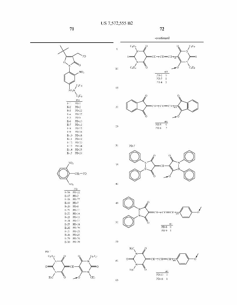

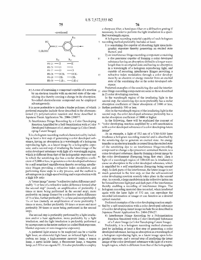
US 7,572,555 B2
-continued
R51
NC
)= CH O-H- C2H5OOC
R52 R51 R52
PD-25 -H HH
PD-26 - C -H PD-27 - C -Cl
PD-28 -OCH -OCH PD-29 -CH -CH PD-30 -CH-i -CH-i
iv) A case of containing a compound capable of a reaction by an electron transfer with an excited state of the sen sitizing dye thereby causing a change in the absorption. So-called electrochromic compound can be employed advantageously.
It is more preferable to include a binder polymer, of which preferred examples include those described in the aforemen tioned (1) polymerization reaction and those described in Japanese Patent Application No. 2004-238.077.
3) Interference Fringe Recording by a Color Developing Reaction Amplified by a Self-Sensitization with a Color Developed Substance of a Latent Image (a Color Devel oping-Latent Image)
It is a hologram recording method characterized by includ ing at least a first step of generating a color developed Sub stance, having no absorption in a wavelength of a hologram reproducing light, as a latent image by a holographic expo Sure, and a second step of irradiating the latent image of the color developed Substance with light of a wavelength region, which is different from that of the holographic exposure and in which the sensitizing dye has a molar absorption coeffi cient of 5,000 or less, to generate a color developed substance by a self-sensitized amplification thereby recording interfer ence fringes providing a refractive index modulation, and performing these steps in a dry process, and the method is advantageous in a high-speed writing and a reproduction with a high S/N ratio.
A“latent image' means “a refractive index difference pref erably /2 or less of a refractive index difference formed after the second step' (namely an amplification of preferably 2 times or more being performed in the second step), more preferably an image formed by a refractive index difference of /s or less, further preferably /10 or less and most preferably /30 or less (namely an amplification of more preferably 5 times or more, further preferably 10 times or more and most preferably 30 times or more being performed in the second step). The second step is preferably performed by a light irradia
tion and/or a heat application, more preferably by a light irradiation, and the light irradiation is preferably performed by an exposure on the entire Surface (so-called flush exposure, blanket exposure or non-imagewise exposure). A preferred light source to be employed can be a visible
light laser, an ultraviolet light laser, an infrared light laser, a carbon arc lamp, a high-pressure mercury lamp, a Xenon lamp, a metal halide lamp, a fluorescent lamp, a tungsten lamp, an LED oran organic EL. It is also preferable to employ
10
15
25
30
35
40
45
50
55
60
65
76 a sharp-cut filter, a band-pass filter or a diffraction grating if necessary, in order to perform the light irradiation in a speci fied wavelength region. A hologram recording material capable of Such hologram
recording method preferably includes at least: 1) a sensitizing dye capable of absorbing light upon holo
graphic exposure thereby generating an excited State thereof, and
2) an interference fringe-recording component containing a dye precursor capable of forming a color developed Substance having an absorption shifted to a longer wave length than in an original state and having no absorption in a wavelength of a hologram reproducing light, and capable of recording interference fringes providing a refractive index modulation through a color develop ment by an electron or energy transfer from an excited state of the sensitizing dye or the color developed sub Stance.
Preferred examples of the sensitizing dye and the interfer ence fringe-recording componentare same as those described in 2) color developing reaction.
In the wavelength region of the irradiating light in the second step, the sensitizing dye more preferably has a molar absorption coefficient of linear absorption of 1000 or less, further preferably 500 or less.
Also in the wavelength region of the irradiating light in the second step, the color developed Substance preferably has a molar absorption coefficient of 1000 or higher.
In the following, there will be explained the concept of “color developing reaction amplified by a self-sensitization with a color developed substance of a color developing-latent image'. As an example, a light of 532 nm of a YAG-SHG laser
irradiates a hologram recording material and is absorbed by the sensitizing dye to generate an excited State. An energy transfer oran electron transfer is caused from the excited state of the sensitizing dye to an interference fringe-recording component to change a dye precursor, contained therein, to a color developed substance, thereby forming a latent image by the color development (foregoing being first step). Then a light of a wavelength region of 350-420 nm is irradiated to cause an absorption in the color developed Substance, which is amplified by a self sensitization (foregoing being second step). In dark parts of the interference, the latent image is not much generated in the first step, so that the self-sensitized color developing reaction scarcely takes place in the second step. As a result, a large modulation in the refractive index can beformed between light part and dark part of the interference thereby enabling a recording of interference fringes. The hologram recording material thus recorded, when irradiated again with the laser light of 532 nm, can reproduce the recorded information or image or can function as a desired optical material.
Preferred examples of the color developing reaction ampli fied by a self-sensitization with a color developed substance of a color developing-latent image include those described in Japanese Patent Application No. 2004-238427.
4) Interference Fringe Recording by a Polymerization Reaction Sensitized with a Color Developed Substance of a Latent Image (a Color Developing-Latent Image)
Preferably, it is a hologram recording method character ized by including at least a first step of generating a color developed substance, having no absorption in a wavelength of a hologram reproducing light, as a latent image upon holo graphic exposure, and a second step of irradiating the latent image of the color developed substance with light of a wave length region, which is different from that of the holographic
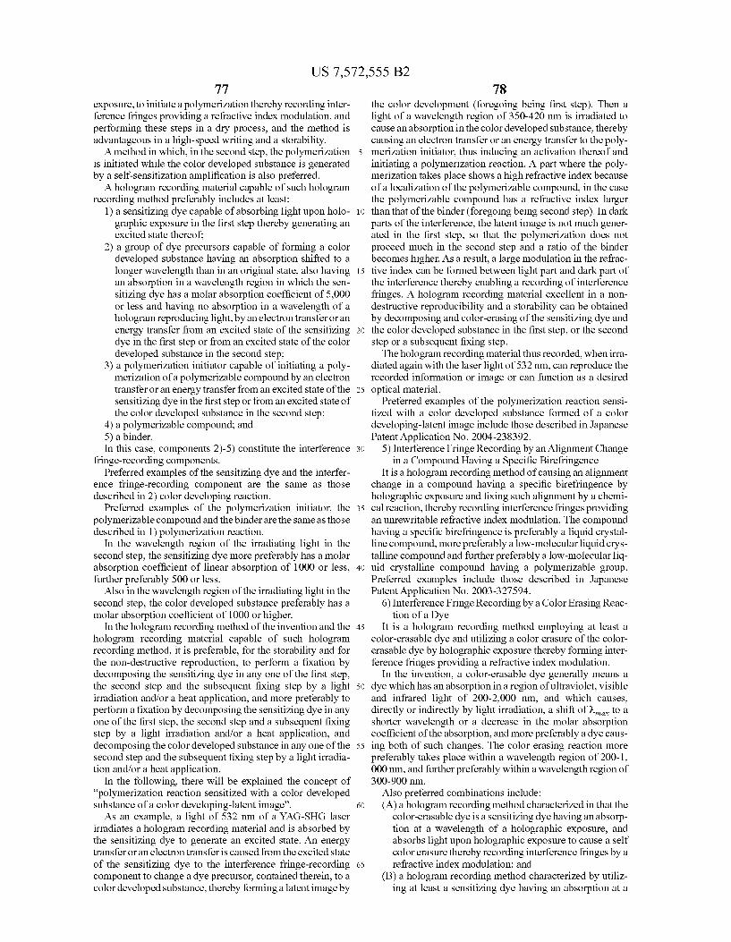
US 7,572,555 B2 77
exposure, to initiate a polymerization thereby recording inter ference fringes providing a refractive index modulation, and performing these steps in a dry process, and the method is advantageous in a high-speed writing and a storability. A method in which, in the second step, the polymerization
is initiated while the color developed substance is generated by a self-sensitization amplification is also preferred. A hologram recording material capable of Such hologram
recording method preferably includes at least: 1) a sensitizing dye capable of absorbing light upon holo
graphic exposure in the first step thereby generating an excited state thereof;
2) a group of dye precursors capable of forming a color developed substance having an absorption shifted to a longer wavelength than in an original state, also having an absorption in a wavelength region in which the sen sitizing dye has a molar absorption coefficient of 5,000 or less and having no absorption in a wavelength of a hologram reproducing light, by an electron transfer oran energy transfer from an excited State of the sensitizing dye in the first step or from an excited state of the color developed Substance in the second step;
3) a polymerization initiator capable of initiating a poly merization of a polymerizable compound by an electron transfer oran energy transfer from an excited State of the sensitizing dye in the first step or from an excited State of the color developed Substance in the second step;
4) a polymerizable compound; and 5) a binder. In this case, components 2)-5) constitute the interference
fringe-recording components. Preferred examples of the sensitizing dye and the interfer
ence fringe-recording component are the same as those described in 2) color developing reaction.
Preferred examples of the polymerization initiator, the polymerizable compound and the binder are the same as those described in 1) polymerization reaction.
In the wavelength region of the irradiating light in the second step, the sensitizing dye more preferably has a molar absorption coefficient of linear absorption of 1000 or less, further preferably 500 or less.
Also in the wavelength region of the irradiating light in the second step, the color developed substance preferably has a molar absorption coefficient of 1000 or higher.
In the hologram recording method of the invention and the hologram recording material capable of Such hologram recording method, it is preferable, for the storability and for the non-destructive reproduction, to perform a fixation by decomposing the sensitizing dye in any one of the first step, the second step and the Subsequent fixing step by a light irradiation and/or a heat application, and more preferably to perform a fixation by decomposing the sensitizing dye in any one of the first step, the second step and a Subsequent fixing step by a light irradiation and/or a heat application, and decomposing the color developed substance in any one of the second step and the Subsequent fixing step by a light irradia tion and/or a heat application.
In the following, there will be explained the concept of "polymerization reaction sensitized with a color developed Substance of a color developing-latent image'. As an example, a light of 532 nm of a YAG-SHG laser
irradiates a hologram recording material and is absorbed by the sensitizing dye to generate an excited State. An energy transfer oran electron transfer is caused from the excited state of the sensitizing dye to the interference fringe-recording component to change a dye precursor, contained therein, to a color developed substance, thereby forming a latent image by
10
15
25
30
35
40
45
50
55
60
65
78 the color development (foregoing being first step). Then a light of a wavelength region of 350-420 nm is irradiated to cause an absorption in the color developed Substance, thereby causing an electron transfer or an energy transfer to the poly merization initiator, thus inducing an activation thereof and initiating a polymerization reaction. A part where the poly merization takes place shows a high refractive index because of a localization of the polymerizable compound, in the case the polymerizable compound has a refractive index larger than that of the binder (foregoing being second step). In dark parts of the interference, the latent image is not much gener ated in the first step, so that the polymerization does not proceed much in the second step and a ratio of the binder becomes higher. As a result, a large modulation in the refrac tive index can be formed between light part and dark part of the interference thereby enabling a recording of interference fringes. A hologram recording material excellent in a non destructive reproducibility and a storability can be obtained by decomposing and color-erasing of the sensitizing dye and the color developed substance in the first step, or the second step or a Subsequent fixing step. The hologram recording material thus recorded, when irra
diated again with the laser light of 532 nm, can reproduce the recorded information or image or can function as a desired optical material.
Preferred examples of the polymerization reaction sensi tized with a color developed substance formed of a color developing-latent image include those described in Japanese Patent Application No. 2004-238392.
5) Interference Fringe Recording by an Alignment Change in a Compound Having a Specific Birefringence
It is a hologram recording method of causing an alignment change in a compound having a specific birefringence by holographic exposure and fixing Such alignment by a chemi cal reaction, thereby recording interference fringes providing an unrewritable refractive index modulation. The compound having a specific birefringence is preferably a liquid crystal line compound, more preferably a low-molecular liquid crys talline compound and further preferably a low-molecular liq uid crystalline compound having a polymerizable group. Preferred examples include those described in Japanese Patent Application No. 2003-327594.
6) Interference Fringe Recording by a Color Erasing Reac tion of a Dye
It is a hologram recording method employing at least a color-erasable dye and utilizing a color erasure of the color erasable dye by holographic exposure thereby forming inter ference fringes providing a refractive index modulation.
In the invention, a color-erasable dye generally means a dye which has an absorption in a region of ultraviolet, visible and infrared light of 200-2,000 nm, and which causes, directly or indirectly by light irradiation, a shift of W to a shorter wavelength or a decrease in the molar absorption coefficient of the absorption, and more preferably a dye caus ing both of Such changes. The color erasing reaction more preferably takes place within a wavelength region of 200-1, 000 nm, and further preferably within a wavelength region of 300-900 nm.
Also preferred combinations include: (A) a hologram recording method characterized in that the
color-erasable dye is a sensitizing dye having an absorp tion at a wavelength of a holographic exposure, and absorbs light upon holographic exposure to cause a self colorerasure thereby recording interference fringes by a refractive index modulation; and
(B) a hologram recording method characterized by utiliz ing at least a sensitizing dye having an absorption at a
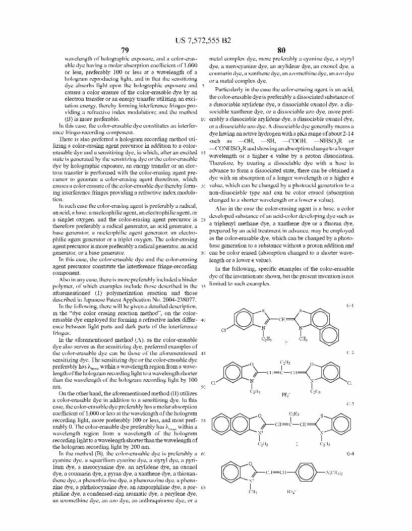
US 7,572,555 B2 79
wavelength of holographic exposure, and a color-eras able dye having a molar absorption coefficient of 1,000 or less, preferably 100 or less at a wavelength of a hologram reproducing light, and in that the sensitizing dye absorbs light upon the holographic exposure and 5 causes a color erasure of the color-erasable dye by an electron transfer or an energy transfer utilizing an exci tation energy, thereby forming interference fringes pro viding a refractive index modulation; and the method (B) is more preferable. 10
In this case, the color-erasable dye constitutes an interfer ence fringe-recording component.
There is also preferred a hologram recording method uti lizing a color-erasing agent precursor in addition to a color erasable dye and a sensitizing dye, in which, after an excited 15 state is generated by the sensitizing dye or the color-erasable dye by holographic exposure, an energy transfer or an elec tron transfer is performed with the color-erasing agent pre cursor to generate a color-erasing agent therefrom, which causes a colorerasure of the color-erasable dye thereby form- 20 ing interference fringes providing a refractive index modula tion.
In Such case the color-erasing agent is preferably a radical, an acid, a base, a nucleophilic agent, an electrophilic agent, or a singlet oxygen, and the color-erasing agent precursor is 25 therefore preferably a radical generator, an acid generator, a base generator, a nucleophilic agent generator, an electro philic agent generator or a triplet oxygen. The color-erasing agent precursor is more preferably a radical generator, an acid generator, or a base generator. 30
In this case, the color-erasable dye and the color-erasing agent precursor constitute the interference fringe-recording component.
Also in any case, there is more preferably included a binder polymer, of which examples include those described in the 35 aforementioned (1) polymerization reaction and those described in Japanese Patent Application No. 2004-238.077.
In the following, there will be given a detailed description, in the “dye color erasing reaction method, on the color erasable dye employed for forming a refractive index differ- 40 ence between light parts and dark parts of the interference fringes.
In the aforementioned method (A), as the color-erasable dye also serves as the sensitizing dye, preferred examples of the color-erasable dye can be those of the aforementioned 45 sensitizing dye. The sensitizing dye or the color-erasable dye preferably has within a wavelength region from a wave length of the hologram recording light to a wavelength shorter than the wavelength of the hologram recording light by 100
. 50
On the other hand, the aforementioned method (B) utilizes a color-erasable dye in addition to a sensitizing dye. In this case, the color-erasable dye preferably has a molar absorption coefficient of 1,000 or less at the wavelength of the hologram recording light, more preferably 100 or less, and most pref 55 erably 0. The color-erasable dye preferably has a within a wavelength region from a wavelength of the hologram recording light to a wavelength shorter than the wavelength of the hologram recording light by 200 nm.
In the method (B), the color-erasable dye is preferably a 60 cyanine dye, a squarilium cyanine dye, a styryl dye, a pyri lium dye, a merocyanine dye, an arylidene dye, an oxonol dye, a coumarin dye, a pyran dye, a Xanthene dye, a thioxan thene dye, a phenothiazine dye, a phenoxazine dye, a phena Zine dye, a phthalocyanine dye, an azaporphiline dye, a por- 65 philine dye, a condensed-ring aromatic dye, a perylene dye, an azomethine dye, an azo dye, an anthraquinone dye, or a
80 metal complex dye, more preferably a cyanine dye, a styryl dye, a merocyanine dye, an arylidene dye, an oxonol dye, a coumarin dye, a Xanthene dye, an azomethine dye, an azo dye or a metal complex dye.
Particularly in the case the color-erasing agent is an acid, the color-erasable dye is preferably a dissociated substance of a dissociable arylidene dye, a dissociable oxonol dye, a dis Sociable Xanthene dye, or a dissociable azo dye, more pref erably a dissociable arylidene dye, a dissociable oxonol dye, or a dissociable azo dye. A dissociable dye generally means a dye having an active hydrogen with a pKa range of about 2-14 such as -OH, -SH, -COOH, -NHSOR or —CONHSOR and showing an absorption change to a longer wavelength or a higher e value by a proton dissociation. Therefore, by treating a dissociable dye with a base in advance to form a dissociated State, there can be obtained a dye with an absorption of a longer wavelength or a higher e value, which can be changed by a photoacid generation to a non-dissociable type and can be color erased (absorption changed to a shorter wavelength or a lowere value).
Also in the case the color-erasing agent is a base, a color developed substance of an acid-color developing dye such as a triphenyl methane dye, a Xanthene dye or a fluoran dye, prepared by an acid treatment in advance, may be employed as the color-erasable dye, which can be changed by a photo base generation to a substance without a proton addition and can be color erased (absorption changed to a shorter wave length or a lowere value).
In the following, specific examples of the color-erasable dye of the invention are shown, but the present invention is not limited to Such examples.
G-1 S S
X-CH={ C
CH5 CH I
G-2
O it. O X-CH= -CH={
C C
CH5 CH5 PF G-3
O ill S X-CH= -CH={
C2H5 I- C2H5
G-4
O
X-ch-en-O)-scal CH BF
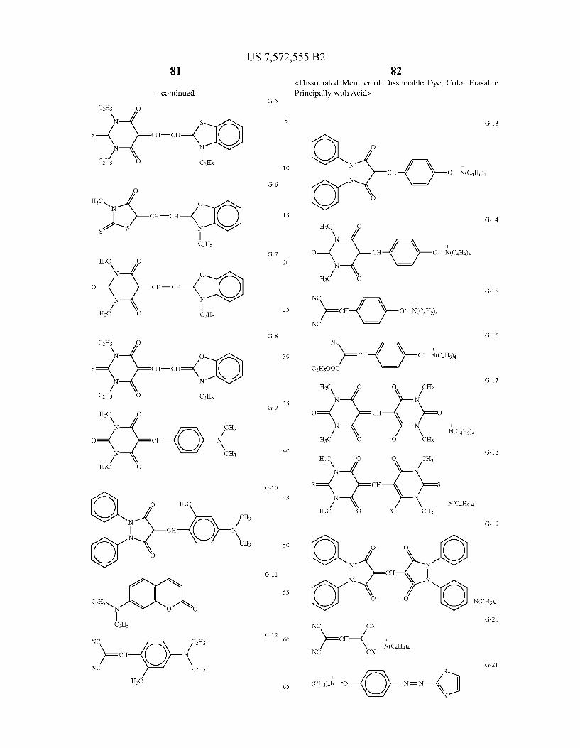


US 7,572,555 B2
-continued -continued G-33
H3C CH3 N1 S S
5 X-CH={ Nt N H
COOH X51 10 G-42
--
H3C O O CH3 NN N1 CH CH 15 S S
3 3 X-CH={ G-34 Nt N
l it. H -N O Nn Xs CH5
CH5 O O CH5 2O G-43 -- X51
COOH
25
M CH
<Acid-Color Developed Substance of Cyanine Base, Color 30 N N Erasable Principally with Bases Xs CH3
G-44
35
y -CH=CH-scCH N 21 N. N H 2
CH5 40 N. CH N
nS6 X51 C2H5
G-35 () G-45 G-36 1
G-37 2 45
CH5 CH5 C C
X-CH=CH-CH-( N N 50
NC -- CN H --
CH HN CH N-CHs X51 215 \ / 56 Xs
G-38 O G-39 1 55 G-46
S S
2 CH=CH-CH ( Also as the color-erasable dye of the invention, there Ca N N also be employed following color-erasable dyes in which a
60 bond is cleaved by an electron transfer from an excited state of Xs CH the sensitizing dye generated by the holographic exposure,
Sl thereby causing a color erasure. 56
Such color-erasable dye is originally a cyanine dye, which G-41 1 65 changes to a cyanine base (leucocyanine dye) by a bond
cleavage by an electron transfer, thereby causing an erasure of an absorption or a shift to a shorter wavelength thereof.
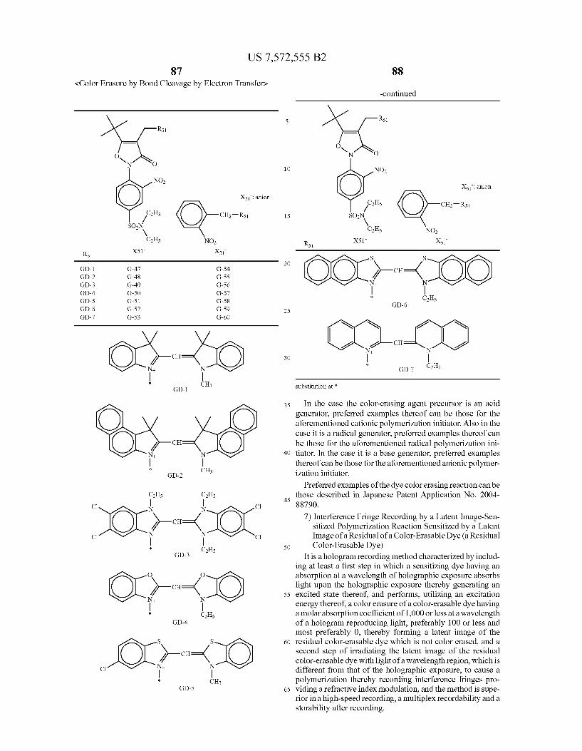
US 7,572,555 B2 87
<Color Erasure by Bond Cleavage by Electron Transfers
- O YN O
NO
Xs: anion
y'alls CH-Rs SON
V C2H5 NO
R51 X51 Xs
GD-1 G-47 G-54 GD-2 G-48 G-55 GD-3 G-49 G-56 GD-4 G-SO G-57 GD-5 G-51 G-58 GD-6 G-52 G-59 GD-7 G-53 G-60
N
: CH3 GD-1
N
: CH3 GD-2
CH5 CH5
C N N C
X-CH={ C C
: CH GD-3 ''
O O
X- CH={ : CH5
GD-4
S S
X-CH={ C
: CH3 GD-5
10
15
25
30
35
40
45
50
55
60
65
-continued
R51
O N O
NO2
Xs: anion
pHs CH-Rs SON
V CH5 NO
Rs 1 X51 X51
S S
X-CH={ : CH5
GD-6
N 21
e -CH
: GD-7 C2H5
Substitution at
In the case the color-erasing agent precursor is an acid generator, preferred examples thereof can be those for the aforementioned cationic polymerization initiator. Also in the case it is a radical generator, preferred examples thereof can be those for the aforementioned radical polymerization ini tiator. In the case it is a base generator, preferred examples thereof can be those for the aforementioned anionic polymer ization initiator.
Preferred examples of the dye colorerasing reaction can be those described in Japanese Patent Application No. 2004 88790.
7) Interference Fringe Recording by a Latent Image-Sen sitized Polymerization Reaction Sensitized by a Latent Image of a Residual of a Color-Erasable Dye (a Residual Color-Erasable Dye)
It is a hologram recording method characterized by includ ing at least a first step in which a sensitizing dye having an absorption at a wavelength of holographic exposure absorbs light upon the holographic exposure thereby generating an excited State thereof, and performs, utilizing an excitation energy thereof, a color erasure of a color-erasable dye having a molar absorption coefficient of 1,000 or less at a wavelength of a hologram reproducing light, preferably 100 or less and most preferably 0, thereby forming a latent image of the residual color-erasable dye which is not color erased, and a second step of irradiating the latent image of the residual color-erasable dye with light of a wavelength region, which is different from that of the holographic exposure, to cause a polymerization thereby recording interference fringes pro viding a refractive index modulation, and the method is Supe rior in a high-speed recording, a multiplex recordability and a storability after recording.

US 7,572,555 B2 89
There is also preferred a hologram recording method char acterized by including at least a first step in which a sensitiz ing dye having an absorption at a wavelength of holographic exposure absorbs light upon the holographic exposure thereby generating an excited State, and performs an energy transfer or an electron transfer with the color-erasing agent precursor described in 6), thereby generating, from the color erasing agent precursor, a color-erasing agent which erases the color-erasable dye thereby forming a latent image of the residual color-erasable dye which is not color erased, and a second step of irradiating the latent image of the residual colorerasable dye with light of a wavelength region, which is different from that of the holographic exposure, to activate a polymerization initiator by an energy transfer or an electron transfer thereby causing a polymerization and recording interference fringes providing a refractive index modulation.
Also a group of compounds capable of performing Such hologram recording method preferably includes at least:
1) a sensitizing dye capable of absorbing light upon holo graphic exposure in the first step thereby generating an excited State;
2) a color-erasable dye having a molar absorption coeffi cient of 1,000 or less at a wavelength of a hologram reproducing light, capable of a color erasure as a result, in the first step, of an electron transfer directly from the excited State of the sensitizing dye or of generation of the color-erasing agent by an energy transfer to the color erasing agent precursor,
3) a polymerization initiator (eventually serving also as the color-erasing agent precursor in 2)) capable of initiating a polymerization of a polymerizable compound by an electron transfer or an energy transfer in the second step from an excited state of the residual color-erasable dye;
4) a polymerizable compound; and 5) a binder.
In the case of performing an energy transfer or an electron transfer to the color-erasing agent precursor in 2), there is preferably included also:
6) a color-erasing agent precursor capable of generating a color-erasing agent by an electron transfer or an energy transfer from the excited state of the sensitizing dye in the first step.
In this case, components 2)-6) constitute the interference fringe-recording components.
Preferred examples of the sensitizing dye are same as those described in 2) color developing reaction.
Preferred examples of the polymerization initiator, the polymerizable compound and the binder are same as those described in 1) polymerization reaction.
In the wavelength region of the irradiating light in the second step, the sensitizing dye more preferably has a molar absorption coefficient of linear absorption of 1000 or less, further preferably 500 or less.
Also in the wavelength region of the irradiating light in the second step, the color-erasable dye preferably has a molar absorption coefficient of 1000 or higher.
In the “latent image-sensitized polymerization reaction sensitized by a latent image of a residual color-erasable dye of the invention, it is also preferable that the color-erasing agent precursor and the polymerization initiator are partly or entirely same and serve for both functions.
In the case of adding a color-erasable dye in addition to the sensitizing dye and in the case the color-erasing agent pre cursor is different from the polymerization initiator (for example the color-erasing agent precursor being an acid gen erator or a base generator, and the polymerization initiator
10
15
25
30
35
40
45
50
55
60
65
90 being a radical polymerization initiator, or the color-erasing agent precursor being a radical generator or a nucleophilic agent generator, and the polymerization initiator being an acid generator or a base generator), it is preferable that the sensitizing dye is capable of performing a sensitization by an electron transfer only to the color-erasing agent precursor and that the polymerization initiator can be sensitized by an elec tron transfer only by the color-erasable dye.
In the hologram recording method of the invention and the hologram recording material capable of Such a hologram recording method, it is preferable, for the storability and for the non-destructive reproduction, to perform a fixation by decomposing the sensitizing dye in any one of the first step, the second step and a Subsequent fixing step by a light irra diation and/or a heat application, and more preferably to perform a fixation by decomposing the sensitizing dye in any one of the first step, the second step and the Subsequent fixing step by a light irradiation and/or a heat application, and decomposing the residual color-erasable dye in any one of the second step and the Subsequent fixing step by a light irradia tion and/or a heat application.
In the following, there will be explained the concept of “latent image-sensitized polymerization reaction sensitized by a latent image of a residual color-erasable dye'. As an example, a light of 532 nm of a YAG-SHG laser
irradiates a hologram recording material and is absorbed by the sensitizing dye to generate an excited State. An energy transfer oran electron transfer is caused from the excited state of the sensitizing dye to the color-erasing agent precursor to generate a color-erasing agent, thereby causing a color era Sure of the color-erasable dye. As a result, a latent image is formed by the residual color-erasable dye (foregoing being first step). Then a light of a wavelength region of 350-420 nm is irradiated to cause an absorption in the latent image of the residual color-erasable dye, thereby causing an electron transfer or an energy transfer to the polymerization initiator, thus inducing an activation thereof and initiating a polymer ization reaction. A part where the polymerization takes place shows a low refractive index because of a localization of the polymerizable compound, in the case the polymerizable com pound has a refractive index smaller than that of the binder (foregoing being second step). In light parts of the interfer ence in the first step, the residual color-erasable dye consti tuting the latent image is present in a low amount, so that the polymerization does not proceed much in the second step and a ratio of the binder becomes higher. As a result, a large modulation in the refractive index can be formed between light part and dark part of the interference thereby enabling a recording of interference fringes. A hologram recording material excellent in a non-destructive reproducibility and a storability can be obtained by decomposing and color-erasing of the sensitizing dye and the residual color-erasable dye in the first step, the second step or the Subsequent fixing step. The hologram recording material thus recorded, when irra
diated again with the laser light of 532 nm, can reproduce the recorded information or image or can function as a desired optical material.
Preferred examples of the latent image-sensitized poly merization reaction sensitized by a latent image of a residual color-erasable dye include those described in Japanese Patent Application No. 2004-88790. The hologram recording material of the invention may
include, in addition to the sensitizing dye, the interference fringe-recording component, the polymerization initiator, the polymerizable compound, the binder, the color-erasable dye, and the color-erasing agent precursor described in the fore going, additives if necessary, such as an electron-donating
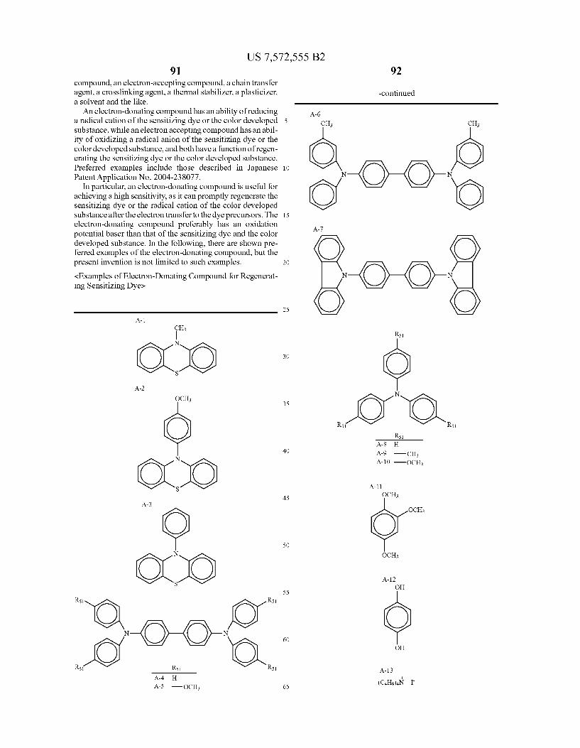
US 7,572,555 B2 91
compound, an electron-accepting compound, a chain transfer agent, a crosslinking agent, a thermal stabilizer, a plasticizer, a solvent and the like. An electron-donating compound has an ability of reducing
a radical cation of the sensitizing dye or the color developed Substance, while an electronaccepting compound has an abil ity of oxidizing a radical anion of the sensitizing dye or the color developed Substance, and both have a function of regen erating the sensitizing dye or the color developed Substance. Preferred examples include those described in Japanese Patent Application No. 2004-238.077.
In particular, an electron-donating compound is useful for achieving a high sensitivity, as it can promptly regenerate the sensitizing dye or the radical cation of the color developed substance after the electron transfer to the dye precursors. The electron-donating compound preferably has an oxidation potential baser than that of the sensitizing dye and the color developed substance. In the following, there are shown pre ferred examples of the electron-donating compound, but the present invention is not limited to Such examples. <Examples of Electron-Donating Compound for Regenerat ing Sensitizing Dyes
A-1 CH3
N
S
A-2
OCH
N
S
A-3
OCO S
R51 R51
R5 R51 R51 A-4 H
5
10
15
25
30
35
40
45
50
55
60
65
92
-continued
A-6
A-10 -OCH
OCH
OCH
A-12 OH
OH
US 7,572,555 B2 93
-continued
A-14
(O) (O)
For the electron-donating compound, there is preferred a phenothiazine compound (such as 10-methylphenothiazine, or 10-(4-methoxyphenyl)phenothiazine), a triphenylamine compound (such as triphenylamine, or tri(4'-methoxyphenyl) amine), or a TPD compound (such as TDP), more preferably a phenothiazine compound and most preferably N-meth ylphenothiazine.
Preferred examples of the chain transfer agent, crosslink ing agent, thermal stabilizer, plasticizer, Solvent and the like are those described in Japanese Patent Application No. 2004 238392.
The chain transfer agent is preferably a thiol, Such as 2-mercaptobenzoxazol, 2-mercaptobenzthiazole, 2-mercap tobenzimidazole, 4-methyl-4H-1,2,4-triazole-3-thiol, p-bro mobenzenethiol, thiocyanuric acid, 1,4-bis(mercaptomethyl) benzene, or p-toluenethiol.
In particular, the chain transfer agent is advantageously employed in the case the polymerization initiator is 2,4,5- triphenylimidazolyl dimer.
In the hologram recording material of the invention, a thermal stabilizer may be added for improving storability in Storage. A useful thermal stabilizer can be hydroquinone, pheni
done, p-methoxyphenol, an alkyl- or aryl-substituted hydro quinone or quinone, cathecol, t-butylcathecol, pyrogallol, 2-naphthol. 2,6-di-t-butyl-p-cresol, phenothiazine, or chlo ranile.
A plasticizer is employed for varying various mechanical properties such as an adhesion property, a flexibility, a hard ness and the like of the hologram recording material. The plasticizer can be, for example, triethylene glycol dicaprylate, triethylene glycol bis(2-ethylhexanoate), tetraethylene glycol diheptanoate, diethyl sebacate, dibutyl suberate, tris(2-ethyl hexyl) phosphate, tricresyl phosphate, dibutyl phthalate, an alcohol or a phenol. The hologram recording material of the invention can be
prepared by an ordinary method. For example, the hologram recording material of the inven
tion can be prepared by a film forming method Such as dis Solving the binder and the components in a solvent and coat ing Such solution with a spin coater or a bar coater. A preferred solvent in Such operation can be, for example,
a ketone solvent such as methyl ethyl ketone, methyl isobutyl ketone, acetone, or cyclohexanone; an ester solvent Such as ethyl acetate, butyl acetate, ethylene glycol diacetate, ethyl lactate, or celloSolve acetate; a hydrocarbon Solvent such as cyclohexane, toluene or Xylene; an ether solvent Such as tetrahydrofuran, dioxane or diethyl ether; a cellosolve solvent such as methyl cellosolve, ethyl cellosolve, butyl cellosolve, or dimethyl celloSolve; an alcohol Solvent such as methanol, ethanol, n-propanol, 2-propanol, n-butanol, or diacetone alcohol; a fluorinated solvent such as 2.2.3,3-tetrafluoropro panol; a halogenated hydrocarbon solvent Such as dichlo romethane, chloroform or 1,2-dichloroethane; an amide Sol
10
15
25
30
35
40
45
50
55
60
65
94 vent such as N,N-dimethylformamide; or a nitrile solvent Such as acetonitrile or propionitrile. The hologram recording material of the invention can be
directly coated on a Substrate by a spin coater, a roll coater or a bar coater, or cast as a film and laminated on a Substrate by an ordinary method, thereby forming a hologram recording material. The “substrate” means an arbitrary natural or synthetic
Support member, preferably Such member that can assume a form of a flexible or rigid film, sheet or plate. The substrate is preferably polyethylene terephthalate,
polyethylene terephthalate undercoated with a resinous mate rial, polyethylene terephthalate subjected to a flame treatment or an electrostatic discharge treatment, cellulose acetate, polycarbonate, polymethyl methacrylate, polyester, polyvi nyl alcohol or glass. The employed solvent may be eliminated by evaporation in
a drying operation. The elimination by evaporation may be performed by heating or under a reduced pressure. The hologram recording material of the invention may also
be formed into a film by melting a binder, containing the components, at a temperature equal to or higher than a glass transition temperature or a melting temperature of the binder and performing a melt extrusion or an injection molding. In Such case, the film strength may be increased by employing a reactive crosslinking binder and curing the film by a crosslinking after the extrusion or molding. In Such a case, for the crosslinking reaction, there can be utilized a radical poly merization reaction, a cationic polymerization reaction, a condensation polymerization reaction, or an addition poly merization reaction. Also there can be utilized methods described in JP-A-2000-250382 and JP-A-2000-172154.
Also there can be advantageously employed a method of dissolving the components in a monomer Solution for form ing a binder, and thermally or optically polymerizing the monomer to obtain a polymer Serving as the binder. Also for Such polymerization, there can be utilized a radical polymer ization reaction, a cationic polymerization reaction, a con densation polymerization reaction, or an addition polymer ization reaction. On the hologram recording material, a protective layer may
be provided for intercepting oxygen. The protective layer can beformed by adhering a plastic film or plate for example of a polyolefin Such as polypropylene or polyethylene, polyvinyl chloride, polyvinylidene chloride, polyvinyl alcohol, poly ethylene terephthalate or cellophane by an electrostatic adhe sion or by a lamination by an extruder, or by coating a solution of such polymer. Also a glass plate may be adhered. Also an adhesive material or a liquid material may be provided, for the purpose of improving the air tightness, between the protective layer and the photosensitive film and/or between the substrate and the photosensitive film.
In the case of employing the hologram recording material of the invention for a holographic memory, the hologram recording material is preferably free from a shrinkage between before and after the hologram recording, in order to improve an S/N ratio at the signal reproduction.
For this purpose, in the hologram recording material of the invention, there can be advantageously employed an inflating agent described in JP-A-2000-86914 or a binder resistant to shrinkage described in JP-A-2000-250382, JP-A-2000 172154 and JP-A-11-344917.
It is also preferable to regulate the spacing of the interfer ence fringes by employing a diffusing element described for example in JP-A-3-46687, JP-A-5-204288 and JP-A-9- 506441.
US 7,572,555 B2 95
In the case of a multiplex recording with an ordinary known polymeras described in JP-A-6-43634, JP-A-2-3082, JP-A-3-50588, JP-A-5-107999, JP-A-8-16078, JP-T-2001 523842 and JP-T-11-512847, the recording in a latter stage of the multiplex recording is performed in a portion where the polymerization has already proceeded considerably, thereby requiring a longer exposure time (a lower sensitivity) for recording a same signal, in comparison with an initial stage of the multiplex recording, thus creating a serious difficulty in the system design. Stated differently, a very narrow range of linear increase of the refractive index modulation as a func tion of the exposure amount has been a major difficulty. On the other hand, the recording method of the present
invention by 2) a color developing reaction, 3) a color devel oping reaction amplified by a self-sensitization with a color developed Substance of a color developing-latent image, or 6) a color erasing reaction of a dye, does not involve a polymer ization in the interference fringe recording, and the recording method by 4) a polymerization reaction sensitized with a color developed Substance of a color developing-latent image or 7) a latent image-sensitized polymerization reaction sen sitized by a latent image of a residual color-erasable dye scarcely involves a polymerization reaction in the holo graphic exposure (first step) and performs a refractive index modulation by a collective polymerization by the flush expo sure in the second step. Therefore, in any of the methods of 2)-4), the multiplex recording can be performed by a large number of times and with a constant exposure amount in any recording operation (i.e., each holographic exposure). namely with a linear increase of the refractive index modula tion as a function of the exposure amount, thereby enabling to obtain a wide dynamic range. Thus, the recording methods of 2)-4), 6) and 7) of the invention, utilizing a color developing process or a latent image amplifying process, are very advan tageous for the multiplex recordability as described above.
Such property is also advantageous for achieving a high density (high capacity), a simplification of a recording system and an improvement in S/N ratio.
Also the sensitizing dye meeting the requirements of the present invention allows to obtain a high transmittance for a recording light and a high sensitivity even in a thick hologram recording material of a film thickness of 100 um or larger, or even 500 um or larger, thereby providing a novel recording material and a novel recording method which can fundamen tally resolve the aforementioned drawbacks and particularly can realize a high sensitivity, a satisfactory storability, a dry processability and a multiplex recordability (high recording density) at the same time. In particular, there is attained, in a high-density optical recording medium (holographic memory), an increase in the recording density by multiplex recording of a large number. The hologram recording material of the invention is appli
cable, in addition to the optical recording medium, also to a three-dimensional display hologram, a holographic optical element (HOE such as a head-up display (HUD) for an auto mobile, a pickup lens for an optical disk, a head-mount dis play, a color filter for a liquid crystal display, a reflecting plate for a reflective liquid crystal display, a lens, a diffraction grating, an interference filter, a coupler for an optical fiber, a photodeflector for a facsimile, and a window pane material for a building), a front cover of books and magazines, a
5
10
15
25
30
35
40
45
50
55
60
65
96 display Such as POP, a gift item, or also a credit card, a banknote, a package, etc. for the purpose of antiforging.
EXAMPLES
In the following there will be shown examples of the present invention based on experimental results, but the invention is not limited to Such examples.
Example 1
Hologram Recording Method by Polymerization Method
A sensitizing dye DEAW (compound S-31), described in JP-A-6-43634, example 1, has a molar absorption coefficient of 17,600 at 532 nm in a film of a composition of the example 1, and is therefore not included in the present invention for a hologram recording wavelength of 532 nm. However, the S-31 can become a sensitizing dye meeting the requirements of the invention at a suitable hologram recording wavelength other than 532 nm. On the other hand, cyanine sensitizing dyes S-92 and S-93
in the composition film of the example 1 respectively have molar absorption coefficients of 2,800 and 1,400 and there fore constitute sensitizing dyes meeting the requirements of the invention for a hologram recording wavelength of 532 nm. As described in JP-A-6-43634, example 1, there were
employed a radical polymerization initiator I-2 by 1.20 mass %, a chain transfer agent MBO by 1.80 mass %, a monomer POEA by 46.5 mass %, cellulose acetate butyrate CAB531-1 as a binder by 50.5 mass %. A sensitizing dye DEAW, S-92 or S-93 was employed, by a calculation in a molar concentration so as to obtain a transmittance of 80% at 500 um and at a hologram recording wavelength of 532 nm and by multipli cation with the molecular weight, and used in a respective amount of 0.0046, 0.035 or 0.065 mass % with respect to the aforementioned solids. These components were dissolved in methylene chloride of a triple amount (2-butanone and acetone employed in combination when necessary) to obtain compositions for the hologram recording material of Com parative Example 1 and Samples 101, 102 of the invention.
Similarly, as in JP-A-6-43634, example 1, there were employed a radical polymerization initiator I-2 by 1.20 mass %, a chain transfer agent MBO by 1.80 mass %, a monomer POEA by 46.5 mass %, cellulose acetate butyrate CAB531-1 as a binder by 50.5 mass %. A sensitizing dye DEAW, S-92 or S-93 was employed, at a fixed molar concentration of 1.42 mmol/l, in a respective amount of 0.057 mass %, 0.069 mass % or 0.065 mass % (corresponding to the sample 102) with respect to the aforementioned solids. These components were dissolved in methylene chloride of a triple amount (2-bu tanone and acetone employed in combination when neces sary) to obtain compositions for the hologram recording material of Comparative Example 2 and Samples 103,102 of the invention. The Comparative Example 2, and the Samples 103, 102 of the invention respectively had a transmittance at a film thickness of 500 um of 6%. 63% and 80%.
Each of the compositions for the hologram recording mate rial of Comparative Example 1, Samples 101, 102 of the invention, Comparative Example 2 and Sample 103 of the invention was coated (coated plural times if necessary) on a glass Substrate with a blade so as to obtain a thickness of about 500 um thereby forming a photosensitive layer, and the sol vent was evaporated by drying at 40°C. for 3 minutes. Then the photosensitive layer was covered with a TAC film (cellu lose triacetate film) to obtain hologram recording materials of
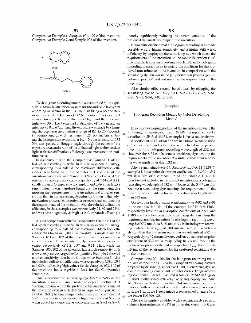
US 7,572,555 B2 97
Comparative Example 1, Samples 101, 102 of the invention, Comparative Example 2 and Sample 103 of the invention.
O
HS –4. MBO O
CH=CHCON-n O
POEA
The hologram recording material was recorded by an expo Sure on a two-beam optical system for transmission hologram recording as shown in the FIGURE, utilizing a second har monic wave of a YAG laser (532 Nm, output 2 W) as a light Source. An angle between the object light and the reference light was 30°. The beam had a diameter of 0.6 cm and an intensity of 8 mW/cm, and the exposure was made by chang ing the exposure time within a range of 0.1 to 200 seconds (irradiation energy within a range of 1.2-1600 m.J/cm). Dur ing the holographic exposure, a He—Ne laser beam of 632 Nm was passed at Bragg's angle through the center of the exposure area, and a ratio of the diffracted light to the incident light (relative diffraction efficiency) was measured on real time basis.
In comparison with the Comparative Example 1 of the hologram recording material in which an exposure energy, corresponding to a half of the maximum diffraction effi ciency, was taken as 1, the Samples 101 and 102 of the invention having a transmittance of 80% at a thickness of 500 um showed an exposure energy respectively of 0.34 and 0.21, Smaller than in Comparative Example 1 and indicating higher sensitivities. It was therefore found that the sensitizing dye meeting the requirements of the invention had a higher sen sitivity than in the sensitizing dye already known in the poly merization process (photopolymer process) and not meeting the requirements of the invention. Also the relative diffraction efficiency in these samples was respectively 91.92 and 92%, and was advantageously as high as in Comparative Example 1.
Also incomparison with the Comparative Example 1 of the hologram recording material in which an exposure energy, corresponding to a half of the maximum diffraction effi ciency, was taken as 1, the Comparative Example 2 and the Samples 103 and 102 of the invention having a same molar concentration of the sensitizing dye showed an exposure energy respectively of 2.2, 0.37 and 0.21. Thus, while the Samples 103,102 of the invention had a high sensitivity with a lower exposure energy, the Comparative Example 2 showed a lower sensitivity than in the Comparative Example 1. Also the relative diffraction efficiency was respectively 35%, 92% and 92%, indicating high values for the Samples 103,102 of the invention but a significant loss for the Comparative Example 2.
This is because the sensitizing dye S-92 or S-93 of the invention, showing a small molar absorption coefficient at 532 nm, remains within the preferable transmittance range of the invention even in a thick film as large as 500 um, while DEAW (S-31) having a large molar absorption coefficient at 532 nm results in an excessively high absorption at 532 nm when added in a same molar concentration as S-92 or S-93,
10
15
25
30
35
40
45
50
55
60
65
98 thereby significantly reducing the transmittance out of the preferred transmittance range of the invention.
It was thus clarified that a hologram recording was made possible with a higher sensitivity and a higher diffraction efficiency, by employing the sensitizing dye which meets the requirements of the invention on the molar absorption coef ficient in the hologram recording wavelength in the hologram recording material So as to satisfy the condition for the pre ferred transmittance of the invention, in comparison with the sensitizing dye known in the polymerization process (photo polymer process) and not meeting the requirements of the invention.
Also similar effects could be obtained by changing the sensitizing dye to S-1, S-6, S-11, S-23, S-71, S-75, S-81, S-88, S-91, S-94, S-95, or S-96.
Example 2
Hologram Recording Method by Color Developing Method
In a color developing method of the invention shown in the following, a sensitizing dye DEAW (compound S-31), described in JP-A-6-43634, example 1, has a molar absorp tion coefficient of 18,300 at 532 nm in a film of a composition of the example 1, and is therefore not included in the present invention for a hologram recording wavelength of 532 nm. However, the S-31 can become a sensitizing dye meeting the requirements of the invention at a Suitable hologram record ing wavelength other than 532 nm.
Also a sensitizing dye S-67, described in JP-A-11-5 12847, example 1, has a molar absorption coefficient of 13,000 at 532 nm in a film of a composition of the example 1, and is therefore not included in the present invention for a hologram recording wavelength of 532 nm. However, the S-67 can also become a sensitizing dye meeting the requirements of the invention at a suitable hologram recording wavelength other than 532 nm.
On the other hand, cyanine sensitizing dyes S-92 and S-93 in the composition film of the example 1 of JP-A-6-43634 respectively have molar absorption coefficients of 2,600 and 1,300 and therefore constitute sensitizing dyes meeting the requirements of the invention for a hologram recording wave length of 532 nm. Also S-92 and S-93 in the hologram record ing material have at 500 nm and 493 nm, which are shorter than the hologram recording wavelength of 532 nm respectively by 32 nm and 39 nm, and have a molar absorption coefficient at 532 nm corresponding to /53 and /106 of the molar absorption coefficient at respective w, thereby sat isfying all the requirements for the preferred sensitizing dye in the invention.
Compositions 201-204 for the hologram recording mate rial and compositions 21-24 for Comparative Examples were prepared by dissolving, under a red light, a sensitizing dye, an electron-donating compound, an interference fringe-record ing component, an additive, and a binder PMMA-EA (poly (methyl methacrylate-5% ethyl acrylate) copolymer, Mw: 101,000) in methylene chloride of 2-4 times amount (in com bination with acetone and acetonitrile if necessary) as shown in Table 1. In Table 1, percentage is represented by mass % to the binder PMMA-EA.
Also each sample was added with a sensitizing dye so as to obtain a transmittance of 71% at a film thickness of 500 um.
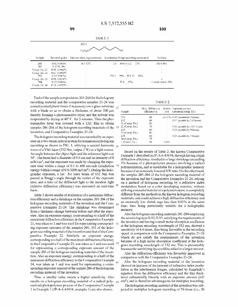
US 7,572,555 B2 99 100
TABLE 1.
SO-3 O
CH o1\-1 N1 No Sample Sensitizing dye Electron-donating compound Interference fringe-recording component Additive
2O1 S-92 O.OS3% A-1 42% I-5 50% + L-2 10% SO-38% 2O2 S-93 0.10%
Comp. Ex. 21 S-310.0062% Comp. Ex. 22 S-67 0.0093%
2O3 S-93 0.08.2% PB-2 20% - DD-33 10% Comp. Ex. 23 S-310.0051%
204 S-93 0.084% E-4 25% trioctyl-amine 10% Comp. Ex. 24 S-310.0052%
Each of the sample compositions 201-204 for the hologram recording material and the comparative samples 21-24 was TABLE 2 coated (coated plural times if necessary) on a glass substrate XX Max. Diffraction Shrink Exposure amount with a blade so as to obtain a thickness of about 500 um Sample efficiency in rate (invention comp. Ex.) thereby forming a photosensitive layer, and the solvent was 2O1 88 O.01% 0.2O itivity 5 ti evaporated by drying at 40°C. for 3 minutes. Then the pho- 2O2 89 <Uytvo 0.17 ER S. tosensitive layer was covered with a TAC film to obtain 21 (Comp. EX.) 82 samples 201-204 of the hologram recording materials of the 25 S"P) 79 1.10 (sensitivity 0.91 times)
2O3 86 0.25 (sensitivity 4 times) invention, and Comparative Examples 21-24. 23 (Comp. EX.) 8O The hologram recording material was recorded by an expo- Comp. Ex.) s 0.20 (sensitivity 5 times)
Sure on a two-beam optical system for transmission hologram 1 N. 91 S.1% recording as shown in FIG. 1, utilizing a second harmonic 30 wave of a YAG laser (532 Nm, output 2 W) as a light SOUC. Based on the results of Table 2, the known Comparative An angle between the object light and the reference light was - - - - 30°. Theb had a di f0.6 dani ity of 8 Example 1 described in JP-A-6-43634, through having a high
e eam had a d1ameter OTU.6 cm and an intensity O diffraction efficiency, resulted in a large shrinkage exceeding mW/cm, and the exposure was made by changing the expo- 5% because of a photopolymer process involving a radical sure time within a range of 0.1 to 400 seconds (irradiation polymerization, and is unsuitable for a holographic memory energy within a range of 0.8-3200 m.J/cm?). During the holo- because of an extremely lowered S/N ratio. On the other hand, graphic exposure, a He Ne laser beam of 632 Nm was the samples 201-204 of the hologram recording material of passed at Bragg's angle through the center of the exposure the invention and the Comparative Examples 21-24, relying area, and a ratio of the diffracted light to the incident light on a method of hologram recording by a refractive index (relative diffraction efficiency) was measured on real-time " modulation based on a color developing reaction, without basis. utilizing a material transfer or a polymerization, is completely
Table 2 shows results of evaluation of a maximum diffrac- different from the methods in the known hologram recording tion efficiency and a shrinkage on the samples 201-204 of the materials, and could achieve a high diffraction, efficiency and hologram recording materials of the invention and the Com- 4s an extremely low shrink rage less than 0.01% at the same parative Examples 21-24. The shrinkage was determined time, thus being particularly Suitable for a holographic from a thickness change between before and after the expo- memory. Sure. Also an exposure energy, corresponding to a half of the Also the hologram recording materials 2O1 -204 employing maximum diffraction efficiency in the Comparative Example the sensitizing dyes S-92, S-93, satisfying the requirements of
the invention and having a small molar absorption coefficient 21, was taken as 1 and was used for representing correspond- 50 at the hologram recording wavelength of 532 nm, showed a ing exposure amounts of the samples 201, 202 of the holo sensitivity of 4-6 times, thus being favorable in the recording gram recording material of the invention and that of the Com- speed, in comparison with the Comparative Examples 21-24 parative Example 22. Similarly al exposure energy, which do not satisfy the requirements of the invention corresponding to a half of the maximum diffraction efficiency because of a high molar absorption coefficient at the holo in the Comparative Example 23, was taken as 1 and was used 55 gram recording wavelength of 532 nm. This is presumably for representing a corresponding exposure amount of the because the sensitizing dye could be added in a larger amount. sample 203 of the hologram recording material of the inven- Also the diffraction efficiency was favorably improved in tion. Also an exposure energy, corresponding to a half of the comparison with the Comparative Examples 21-24. maximum diffraction efficiency in the Comparative Example 60 Also the hologram recording material of the invention 24, was taken as 1 and was used for representing a corre- showed an increase of An (amount of refractive index modu sponding exposure amount of the sample 204 of the hologram lation in the interference fringes, calculated by Kugelnik's recording material of the invention. equation from the diffraction efficiency and the film thick
Thus, a smaller value means a higher sensitivity. Also ness) Substantially linearly with an exposure amount (m.J/ results on a hologram recording material of a radical poly- 65 cm), and is therefore advantageous for multiplex recording. merized photopolymer process of the Comparative Example 1 in Example 1 (JP-A-6-43634, example 1) are also shown.
The hologram recording material of the invention was Sub jected to multiplex hologram recording of 50 times (i.e., 50
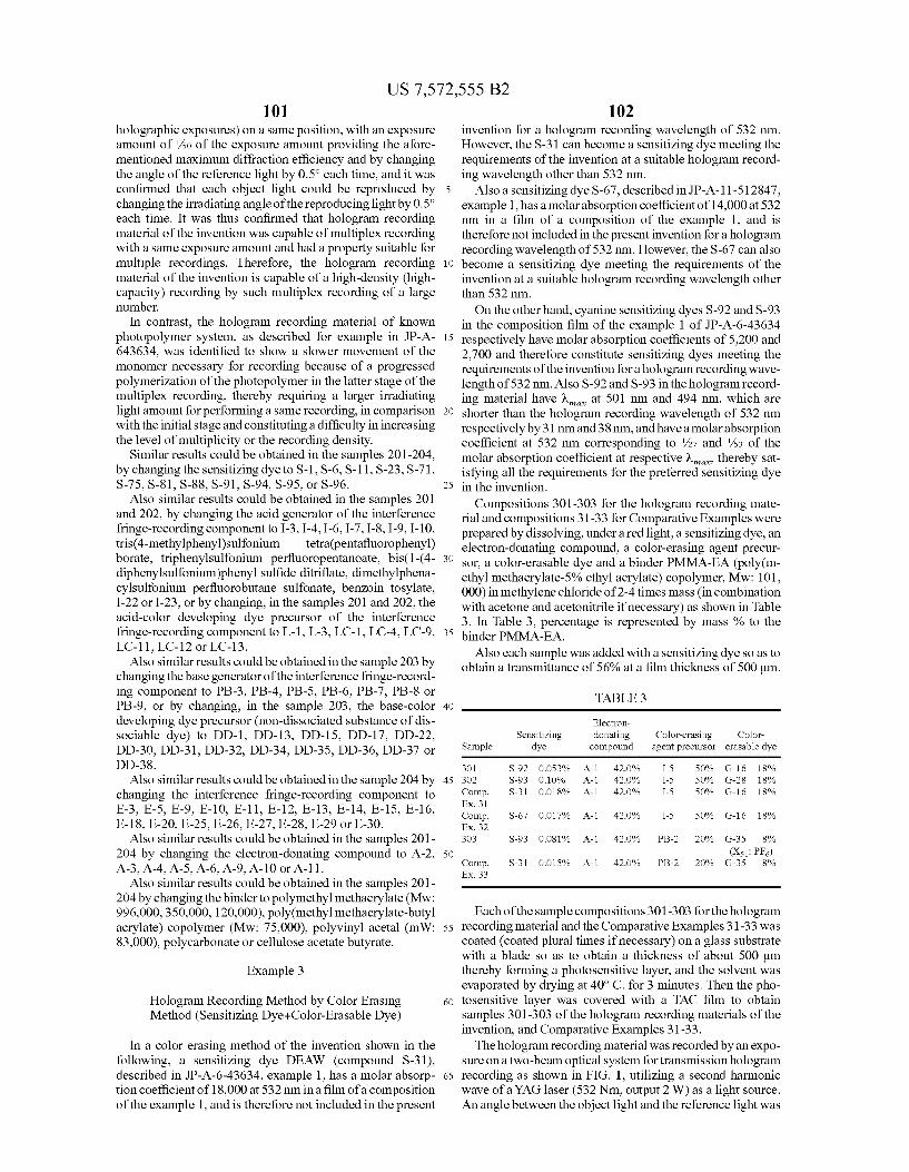
US 7,572,555 B2 101
holographic exposures) on a same position, with an exposure amount of /SO of the exposure amount providing the afore mentioned maximum diffraction efficiency and by changing the angle of the reference light by 0.5° each time, and it was confirmed that each object light could be reproduced by changing the irradiating angle of the reproducing light by 0.5° each time. It was thus confirmed that hologram recording material of the invention was capable of multiplex recording with a same exposure amount and had a property Suitable for multiple recordings. Therefore, the hologram recording material of the invention is capable of a high-density (high capacity) recording by Such multiplex recording of a large number.
In contrast, the hologram recording material of known photopolymer system, as described for example in JP-A- 643634, was identified to show a slower movement of the monomer necessary for recording because of a progressed polymerization of the photopolymer in the latter stage of the multiplex recording, thereby requiring a larger irradiating light amount for performing a same recording, in comparison with the initial stage and constituting a difficulty in increasing the level of multiplicity or the recording density.
Similar results could be obtained in the samples 201-204. by changing the sensitizing dye to S-1, S-6, S-11, S-23, S-71, S-75, S-81, S-88, S-91, S-94, S-95, or S-96.
Also similar results could be obtained in the samples 201 and 202, by changing the acid generator of the interference fringe-recording component to I-3, I-4, I-6, I-7, I-8, I-9, I-10, tris(4-methylphenyl)sulfonium tetra(pentafluorophenyl) borate, triphenylsulfonium perfluoropentanoate, bis(1-(4- diphenylsulfonium)phenyl sulfide ditriflate, dimethylphena cylsulfonium perfluorobutane sulfonate, benzoin tosylate, I-22 or I-23, or by changing, in the samples 201 and 202, the acid-color developing dye precursor of the interference fringe-recording component to L-1, L-3, LC-1, LC-4. LC-9, LC-11, LC-12 or LC-13.
Also similar results could be obtained in the sample 203 by changing the base generator of the interference fringe-record ing component to PB-3, PB-4, PB-5, PB-6, PB-7, PB-8 or PB-9, or by changing, in the sample 203, the base-color developing dye precursor (non-dissociated Substance of dis sociable dye) to DD-1, DD-13, DD-15, DD-17, DD-22, DD-30, DD-31, DD-32, DD-34, DD-35, DD-36, DD-37 or DD-38.
Also similar results could be obtained in the sample 204 by changing the interference fringe-recording component to E-3, E-5, E-9, E-10, E-11, E-12, E-13, E-14, E-15, E-16, E-18, E-20, E-25, E-26, E-27, E-28, E-29 or E-30.
Also similar results could be obtained in the samples 201 204 by changing the electron-donating compound to A-2, A-3, A-4, A-5, A-6, A-9, A-10 or A-11.
Also similar results could be obtained in the samples 201 204 by changing the binder to polymethyl methacrylate (Mw: 996,000,350,000, 120,000), poly(methyl methacrylate-butyl acrylate) copolymer (Mw: 75,000), polyvinyl acetal (mW: 83,000), polycarbonate or cellulose acetate butyrate.
Example 3
Hologram Recording Method by Color Erasing Method (Sensitizing Dye--Color-Erasable Dye)
In a color erasing method of the invention shown in the following, a sensitizing dye DEAW (compound S-31), described in JP-A-6-43634, example 1, has a molar absorp tion coefficient of 18,000 at 532 nm in a film of a composition of the example 1, and is therefore not included in the present
10
15
25
30
35
40
45
50
55
60
65
102 invention for a hologram recording wavelength of 532 nm. However, the S-31 can become a sensitizing dye meeting the requirements of the invention at a Suitable hologram record ing wavelength other than 532 nm.
Also a sensitizing dye S-67, described in JP-A-11-5 12847, example 1, has a molar absorption coefficient of 14,000 at 532 nm in a film of a composition of the example 1, and is therefore not included in the present invention for a hologram recording wavelength of 532 nm. However, the S-67 can also become a sensitizing dye meeting the requirements of the invention at a suitable hologram recording wavelength other than 532 nm. On the other hand, cyanine sensitizing dyes S-92 and S-93
in the composition film of the example 1 of JP-A-6-43634 respectively have molar absorption coefficients of 5,200 and 2,700 and therefore constitute sensitizing dyes meeting the requirements of the invention for a hologram recording wave length of 532 nm. Also S-92 and S-93 in the hologram record ing material have at 501 nm and 494 nm, which are shorter than the hologram recording wavelength of 532 nm respectively by 31 nm and 38 nm, and have a molar absorption coefficient at 532 nm corresponding to /27 and /33 of the molar absorption coefficient at respective w, thereby sat isfying all the requirements for the preferred sensitizing dye in the invention.
Compositions 301-303 for the hologram recording mate rial and compositions 31-33 for Comparative Examples were prepared by dissolving, under a red light, a sensitizing dye, an electron-donating compound, a color-erasing agent precur sor, a color-erasable dye and a binder PMMA-EA (poly(m- ethyl methacrylate-5% ethyl acrylate) copolymer, Mw: 101, 000) in methylene chloride of 2-4 times mass (in combination with acetone and acetonitrile if necessary) as shown in Table 3. In Table 3, percentage is represented by mass % to the binder PMMA-EA.
Also each sample was added with a sensitizing dye so as to obtain a transmittance of 56% at a film thickness of 500 um.
TABLE 3
Electron Sensitizing donating Color-erasing Color
Sample dye compound agent precursor erasable dye
301 S-92 O.OS3% A-1 42.0% I-5 50% G-1 6 18% 3O2 S-93 O.10% A-1 42.0% I-5 50% G-28. 18% Comp. S-31 OO18% A-1 42.0% I-5 50% G-1 6 18% Ex. 31 Comp. S-67 OO17% A-1 42.0% I-5 50% G-1 6 18% Ex. 32 303 S-93 O.O81% A-1 42.0% PB-2 20% G-3S 8%
(Xs: PF) Comp. S-31 OO15% A-1 42.0% PB-2 20% G-3S 8% Ex. 33
Each of the sample compositions 301-303 for the hologram recording material and the Comparative Examples 31-33 was coated (coated plural times if necessary) on a glass Substrate with a blade so as to obtain a thickness of about 500 um thereby forming a photosensitive layer, and the solvent was evaporated by drying at 40°C. for 3 minutes. Then the pho tosensitive layer was covered with a TAC film to obtain samples 301-303 of the hologram recording materials of the invention, and Comparative Examples 31-33. The hologram recording material was recorded by an expo
Sure on a two-beam optical system for transmission hologram recording as shown in FIG. 1, utilizing a second harmonic wave of a YAG laser (532 Nm, output 2 W) as a light source. An angle between the object light and the reference light was
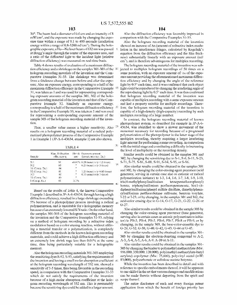
US 7,572,555 B2 103
30°. The beam had a diameter of 0.6 cm and an intensity of 8 mW/cm, and the exposure was made by changing the expo sure time within a range of 0.1 to 400 seconds (irradiation energy within a range of 0.8-3200 m.J/cm). During the holo graphic exposure, a He—Nelaserbeam of 632 nm was passed at Bragg's angle through the center of the exposure area, and a ratio of the diffracted light to the incident light (relative diffraction efficiency) was measured on real-time basis.
Table 4 shows results of evaluation of a maximum diffrac tion efficiency and a shrinkage on the samples 301-303 of the hologram recording materials of the invention and the Com parative Examples 31-33. The shrinkage was determined from a thickness change between before and after the expo Sure. Also an exposure energy, corresponding to a half of the maximum diffraction efficiency in the Comparative Example 31, was taken as 1 and was used for representing correspond ing exposure amounts of the samples 301, 302 of the holo gram recording material of the invention and that of the Com parative Example 32. Similarly an exposure energy, corresponding to a half of the maximum diffraction efficiency in the Comparative Example 33, was taken as 1 and was used for representing a corresponding exposure amount of the sample 303 of the hologram recording material of the inven tion.
Thus, a smaller value means a higher sensitivity. Also results on a hologram recording material of a radical poly merized photopolymer process of the Comparative Example 1 in Example 1 (JP-A-6-43634, example 1) are also shown.
TABLE 4
Max. Diffraction Shrink Exposure amount Sample efficiency in rate (invention comp. Ex.)
301 91 <0.01% 0.24 (sensitivity 4.2 times) 3O2 93 0.20 (sensitivity 5 times) 31 (Comp. EX.) 84 32 (Comp. EX.) 81 1.20 (sensitivity 0.83 times) 303 86 0.33 (sensitivity 3 times) 33 (Comp. EX.) 8O 1 (Comp. Ex.) 91 S.1%
Based on the results of Table 4, the known Comparative Example 1 described in JP-A-6-43634, through having a high diffraction efficiency, resulted in a large shrinkage exceeding 5% because of a photopolymer process involving a radical polymerization, and is unsuitable for a holographic memory because of an extremely lowered S/N ratio. On the other hand, the samples 301-303 of the hologram recording material of the invention and the Comparative Examples 31-33, relying on a method of hologram recording by a refractive index modulation based on a color erasing reaction, without utiliz ing a material transfer or a polymerization, is completely different from the methods in the known hologram recording materials, and could achieve a high diffraction efficiency and an extremely low shrink rage less than 0.01% at the same time, thus being particularly Suitable for a holographic memory.
Also the hologram recording materials 301-303 employing the sensitizing dyes S-92, S-93, satisfying the requirements of the invention and having a small molar absorption coefficient at the hologram recording wavelength of 532 nm, showed a sensitivity of 3-5 times, thus being favorable in the recording speed, in comparison with the Comparative Examples 31-33 which do not satisfy the requirements of the invention because of a high molar absorption coefficient at the holo gram recording wavelength of 532 nm. This is presumably because the sensitizing dye could be added in a larger amount.
5
104 Also the diffraction efficiency was favorably improved in
comparison with the Comparative Examples 31-33. Also the hologram recording material of the invention
showed an increase of An (amount of refractive index modu lation in the interference fringes, calculated by Kugelnik's equation from the diffraction efficiency and the film thick ness) Substantially linearly with an exposure amount (m.J/ cm), and is therefore advantageous for multiplex recording. The hologram recording material of the invention was Sub
10 jected to multiplex hologram recordings of 50 times on a
15
25
30
35
40
45
50
55
60
65
same position, with an exposure amount of /SO of the expo Sure amount providing the aforementioned maximum diffrac tion efficiency and by changing the angle of the reference light by 0.5° each time, and it was confirmed that each object light could be reproduced by changing the irradiating angle of the reproducing light by 0.5° each time. It was thus confirmed that hologram recording material of the invention was capable of multiplex recording with a same exposure amount and had a property Suitable for multiple recordings. There fore, the hologram recording material of the invention is capable of a high-density (high-capacity) recording by Such multiplex recording of a large number.
In contrast, the hologram recording material of known photopolymer system, as described for example in JP-A-6- 43634, was identified to show a slower movement of the monomer necessary for recording because of a progressed polymerization of the photopolymer in the latter stage of the multiplex recording, thereby requiring a larger irradiating light amount for performing a same recording, in comparison with the initial stage and constituting a difficulty in increasing the level of multiplicity or the recording density.
Similar results could be obtained in the samples 301 and 302, by changing the sensitizing dye to S-1, S-6, S-11, S-23, S-71, S-75, S-81, S-88, S-91, S-94, S-95, or S-96.
Also similar results could be obtained in the samples 301 and 302, by changing the color-erasing agent precursor (acid generator, serving in certain case also as cationic or radical polymerization initiator) to I-3, I-4, I-6, I-7, I-8, I-9, I-10, tris(4-methylphenyl)sulfonium tetra(pentafluorophenyl) borate, triphenylsulfonium perfluoropentanoate, bis(1-(4- diphenylsulfonium)phenyl sulfide ditriflate, dimethylphena cylsulfonium perfluorobutane Sulfonate, benzoin tosylate, I-22 or I-23, or by changing, in the samples 301 and 302, the acid-color erasing dye to G-14, G-17, G-21, G-22, G-26 or G-27.
Also similar results could be obtained in the sample 303 by changing the color-erasing agent precursor (base generator, serving also in certain cases as anionic polymerization initia tor) to PB-3, PB-4, PB-5, PB-6, PB-7, PB-8 or PB-9, or by changing, in the sample 303, the base-color-erasable dye to G-29, G-32, G-38, G-40, G-42, G-43, G-44 or G-45.
Also similar results could be obtained in the samples 301 303 by changing the electron-donating compound to A-2, A-3, A-4, A-5, A-6, A-9, A-10 or A-11.
Also similar results could be obtained in the samples 301 303 by changing the binder to polymethyl methacrylate (Mw: 996,000,350,000, 120,000), poly(methyl methacrylate-butyl acrylate) copolymer (Mw: 75,000), polyvinyl acetal (mW: 83,000), polycarbonate or cellulose acetate butyrate. While the invention has been described in detail and with
reference to specific embodiments thereof, it will be apparent to one skilled in the art that various changes and modifications can be made therein without departing from the spirit and Scope thereof. The entire disclosure of each and every foreign patent
application from which the benefit of foreign priority has
US 7,572,555 B2 105
been claimed in the present application is incorporated herein by reference, as if fully set forth herein. What is claimed is: 1. A hologram recording material comprising: a sensitizing dye capable of absorbing light having a holo gram recording wavelength to generate an excited State thereof, and
an interference fringe-recording component capable of recording interference fringes providing a refractive index modulation by an electron or energy transfer from the excited state,
the hologram recording material has a thickness of 500 um or larger,
wherein the sensitizing dye in the hologram recording material comprises at least one of a cyanine dye and a merocyanine dye, and has a molar absorption coefficient within a range of 1 to 10,000 at the hologram recording wavelength; and
the interference fringe-recording component is a compo nent capable of recording the interference fringes pro viding a refractive index modulation by a latent image sensitized polymerization reaction sensitized by a latent image of a residual of a color-erasable dye, and
the component records the interference fringes by a method comprising:
a first step in which: the sensitizing dye absorbs light upon holographic expo
Sure to generate the excited State thereof, a color of a color-erasable dye is erased by at least one of:
an energy or electron transfer from the excited State of the sensitizing dye directly to the color-erasable dye; and a color-erasing agent formed by an energy or elec tron transfer from the excited state of the sensitizing dye to a color-erasing agent precursor, the color-erasing agent precursor comprising at least one of a radical generator, an acid generator, a base generator, a nucleo philic agent generator, an electrophilic agent generator or a triplet oxygen, and
a residual of the color-erasable dye forms a latent image: and
a second step of irradiating the latent image of the residual of the color-erasable dye with light of a wavelength region, which is different from that of the holographic exposure, to cause a polymerization reaction by activat ing a polymerization initiator as a result of an energy or electron transfer from the residual of the color-erasable dye.
2. The hologram recording material according to claim 1, wherein the sensitizing dye in the hologram recording mate rial has a molar absorption coefficient within a range of 5 to 2,500 at the hologram recording wavelength.
3. The hologram recording material according to claim 1, wherein the sensitizing dye in the hologram recording mate rial has an absorption maximum within a region shorter in wavelength than the hologram recording wavelength by 20 to 100 nm.
4. The hologram recording material according to claim 1, wherein the sensitizing dye in the hologram recording mate rial has a molar absorption coefficient equal to or less than /10 of the molar absorption coefficientatan absorption maximum thereof.
5. The hologram recording material according to claim 1, wherein the sensitizing dye in the hologram recording mate rial has a molar absorption coefficient equal to or less than /20 of the molar absorption coefficient at the absorption maxi mum thereof.
10
15
25
30
35
40
45
50
55
60
65
106 6. The hologram recording material according to claim 1,
wherein the sensitizing dye is a cyanine dye represented by formula (1):
7
4
7.
O O 6
X-CR=CR., CR-( O - Y is
Cly R R 2
wherein R and Reach independently represents an alkyl group, an alkenyl group, an alkynyl group or a cycloalkyl group; R and Reach independently repre sents a Substituent; and a3 and a4 each independently represents an integer of 0 to 4, and in a case a3 or a4 is 2 or larger, plural RS or RS are mutually same or different and may be mutually bonded to form a ring; Rs. Re and R, each independently represents a hydrogen atom or a Substituent, and may be mutually bonded to form a ring; n1 represents an integer of 0 to 2: CI represents a charge neutralizing ion; and y represents a number required for neutralizing the charge.
7. The hologram recording material according to claim 6. wherein a3 and a4 are both Zero, n1 is 1, and the hologram recording wavelength is 532 nm.
8. The hologram recording material according to claim 1, wherein the sensitizing dye is a merocyanine dye represented by formula (2):
R11 O V 7 N
X—( CR1s CR16 n2 5 N N R.) / 4 al4
R12 O R13
wherein X represents O or S:X represents—O——S , —NR—, or—CRR - RandR each indepen dently represents a hydrogen atom, an alkyl group, an alkenyl group, an alkynyl group, a cycloalkyl group, an aryl group or a heterocyclic group; R17, R1s and Rio each independently represents an alkyl group, an alkenyl group, an alkynyl group, a cycloalkyl group, an aryl group or a heterocyclic group; R represents an alkyl group, an alkenyl group, an alkynyl group, or a cycloalkyl group; Ra represents a Substituent; a 14 rep resents an integer of 0 to 4, and in case a14 is 2 or larger, plural Ras are mutually same or different or may be mutually bonded to form a ring; Rs and Reach inde pendently represents a hydrogen atom or a Substituent, and may be mutually bonded to form a ring; and n2 represents an integer of 0 to 2.
9. The hologram recording material according to claim 8. wherein n2 is 1, and the hologram recording wavelength is 532 nm.
10. The hologram recording material according to claim 1, which has the sensitizing dye in Such an amount as to have an optical transmittance of 30 to 90% when the hologram recording material is irradiated with the light having the holo gram recording wavelength.
US 7,572,555 B2 107
11. The hologram recording material according to claim 1, wherein
the sensitizing dye absorbs the light upon holographic exposure in the first step to generate the excited State thereof, and
the hologram recording material further comprises: a color-erasable dye capable of erasing a color thereof in
the first step as a result of at least one of an energy or electron transfer directly from the excited state of the sensitizing dye; and an generation of the color-erasing agent by an energy or electron transfer from the excited state of the sensitizing dye to the color-erasing agent precursor, the color-erasable dye having a molar absorp tion coefficient of 1,000 or less at a wavelength of a hologram reproducing light;
a polymerizable compound; a polymerization initiator capable of initiating a polymer
ization of the polymerizable compound by an electron or energy transfer from the excited state of the residual of the color-erasable dye in the second step; and
a binder. 12. The hologram recording material according to claim 1,
wherein the interference fringes are unrewritable. 13. An optical recording medium comprising a hologram
recording material according to claim 1. 14. The optical recording medium according to claim 13,
wherein the hologram recording material is stored in a light shielding cartridge.
15. A hologram recording method comprising recording interference fringes providing a refractive index modulation in a hologram recording material by at least one of 1) a polymerization reaction, 2) a color developing reaction, 3) a color developing reaction amplified by a self-sensitization with a color developed Substance of a latent image, 4) a polymerization reaction sensitized with a color developed Substance of a latent image, 5) an alignment change in a compound having a specific birefringence, and 6) a color erasing reaction of a dye, and a latent image-sensitized poly merization reaction sensitized by a latent image of a residual of a color-erasable dye, and
the recording of the interference fringes comprising: a first step in which: the sensitizing dye absorbs light upon holographic expo
Sure to generate the excited State thereof,
10
15
25
30
35
40
108 a color of a color-erasable dye is erased by at least one of:
an energy or electron transfer from the excited State of the sensitizing dye directly to the color-erasable dye; and a color-erasing agent formed by an energy or elec tron transfer from the excited state of the sensitizing dye to a color-erasing agent precursor, the color-erasing agent precursor comprising at least one of a radical generator, an acid generator, a base generator, a nucleo philic agent generator, an electrophilic agent generator or a triplet oxygen, and
a residual of the color-erasable dye forms a latent image: and
a second step of irradiating the latent image of the residual of the color-erasable dye with light of a wavelength region, which is different from that of the holographic exposure, to cause a polymerization reaction by activat ing a polymerization initiator as a result of an energy or electron transfer from the residual of the color-erasable dye,
wherein the hologram recording material comprising: a sensitizing dye capable of absorbing light having a holo gram recording wavelength to generate an excited State thereof, and
an interference fringe-recording component capable of recording interference fringes providing a refractive index modulation by an electron or energy transfer from the excited state,
the hologram recording material has a thickness of 500 um or larger,
wherein the sensitizing dye in the hologram recording material comprises at least one of a cyanine dye and a merocyanine dye, and has a molar absorption coefficient within a range of 1 to 10,000 at the hologram recording wavelength.
16. The hologram recording method according to claims 15, wherein a multiplex hologram recording is performed by effecting the holographic exposure 10 times or more.
17. The hologram recording method according to claim 16, wherein the multiplex hologram recording is performed under a common exposure amount in each holographic expo SUC.