2 gerät anschließen
TRANSCRIPT

1 2
1
2
3
5
4
8
3
1
3
2
1
32
6
7
11.1
1.2
1.3
1.4 Mounting the device – Gerät anbauen
1.4
2.1
2.2
2.3
Mounting the device – Gerät anbauen
RESTREST
40 °C
0 °C
40 °C
0 °C
45 °C
0 °C
50 °C
0 °C
Click!4
Quick Install Guide
A5E49178716-AA03/2020SIMATIC IOT
SIMATIC IOT2050
SIMATIC
Connecting the protective earth – Schutzleiter anschließen
Connecting the power supply – Stromversorgung anschließen
Switching on the device –
Before mounting and commissioning – Vor Einbau und Inbetriebnahme
Mounting the deviceGerät einbauen
WICHTIG: Beachten Sie alle dem Gerät beiliegenden Dokumente und die Betriebsanleitung, bevor Sie das Gerät einbauen und anschließen. Die vollständige Dokumentation des Geräts finden Sie im Internet http://www.siemens.de/simatic-ipc-doku-portal
IMPORTANT: observe all documents enclosed with the device and the operating instructions manual before mounting and connecting the device. You find the complete documentation of the internethttp://www.siemens.com/simatic-ipc-doku-portal
Das Handbuchsymbol weist auf detaillierte Informationen in der Betriebsanleitung hin.The manual symbol refers to detailed information in the operating instructions.
Valid Mounting positions – Zulässige Einbaulagen
Scope of delivery – Lieferumfang
Horizontal/horizontal
One SIMATIC IOT device, one terminal connector, one mounting accessory kit including one mounting clamp, two mounting brackets and screws. No accessories such Micro SD card or and cables.
Beachten Sie beim Einsatz im Bereich Industrial Control Equipment entsprechend UL61010‑2‑201, dass das Gerät als "Open Equipment" klassifiziert ist. Voraussetzung für die Zulassung bzw. den Betrieb nach UL61010‑2‑201 ist deshalb der Einbau des Geräts in ein der UL61010‑2‑201 entsprechendes Gehäuse.
When the device is used in the area of Industrial Control Equipment in accordance with UL61010‑2‑201, note that the device is classified as "Open Equipment ". A UL61010‑2‑201 conform enclosure is therefore a mandatory requirement for approval or operation according to UL61010‑2‑201.
Free space required around the device - Erforderlicher Freiraum um das Gerät
50 mm
50 mm
Vertical mounting on DIN rails / vertikal hutschienenmontage
2
2
1
1
3
3
Click!4
Horizontal mounting on DIN rails / horizontal hutschienenmontage
Vertical wall mounting / vertikale wandmontage
Horizontal wall mounting / horizontale wandmontage
Connecting the deviceGerät anschließen2
50 mm
50 mm
M4
2.5 mm²
T20
2
1
Das Gerät darf nur an eine DC 12...24-V‑Stromversorgung angeschlossen werden, die den Anforde-rungen einer sicheren Kleinspannung (SELV) gemäß der IEC/EN/DIN EN/UL 61010‑1 entspricht.Gibt es Spannungsspitzen auf den Stromversorgungsleitungen, dann verwenden Sie eine Schutzeinrichtung in Form eines Varistors (MOV) UMOV = Urated x 1.2 (BLITZDUCTOR BVT AVD 24 (918 422) oder kompatibel).
The device must only be connected to a 12 to 24 VDC power supply which meets the requirements of safe extra low voltage (SELV) according to IEC/EN/DIN EN/UL 61010-1.If there are voltage peaks on power supply lines, use a protective device in the form of a varistor (MOV) UMOV = U-rated x 1.2 (BLITZDUCTOR BVT AVD 24 (918 422) or compatible).
POWER OFF
2
DC 12 to 24 VPowerSupply
+–
3
1
Tightening torque: 0.56 NmWire range: 0.75 to 2.5 mmRated temperature of wire: 70 Conductor material: Cu
°C
Torque: 1 Nm
Torque: 0.6 Nm
Torque: 0.6 Nm
Torque: 0.6 Nm
Torque: 0.6 Nm
POWER ON
DC 12 to 24 VPowerSupply
PWR
12
Gerät einschalten
0.5 x 2
2
Vertical/vertical, preferred/Empfohlen
Ein SIMATIC IOT-Gerät, ein Klemmenanschluss, ein Montagezubehör-Set mit einer Montage--klemme, zwei Montagewinkeln und -schrauben; kein Zubehör wie Micro SD-Karte und -Kabel.
Disclaimer of LiabilityWe have reviewed the contents of this publication to ensure consistency with the hardware and software described. Since variance cannot be precluded entirely, we cannot guarantee full consistency. However, the information in this publication is reviewed regularly and any necessary corrections are included in subsequent editions.
HaftungsausschlussWir haben den Inhalt der Druckschrift auf Übereinstimmung mit der beschriebenen Hard- und Software geprüft. Dennoch können Abweichungen nicht ausgeschlossen werden, so dass wir für die vollständige Übereinstimmung keine Gewähr übernehmen. Die Angaben in dieser Druckschrift werden regelmäßig überprüft, notwendige Korrekturen sind in den nachfolgenden Auflagen enthalten.
Siemens AGDI FAPostfach 48 4890026 NÜRNBERG
IllustrationsThis document contains illustrations of the described devices and accessories. The illustrations may deviate from the particularities of the delivered device and accessories.
AbbildungenDas vorliegende Dokument enthält Abbildungen zu den beschriebenen Geräten und Zubehör.Die Abbildungen können bezogen auf das gelieferte Gerät und Zubehör in Einzelheiten abweichen.
Central Technical SupportTechnische Support-Zentrale
https://support.industry.siemens.com
Service and spare partsReparatur und Ersatzteile
https://support.industry.siemens.com/sc/de/en/sc
© Siemens AG 2020. All rights reservedA5E49178716-AA, 03/2020
3.4
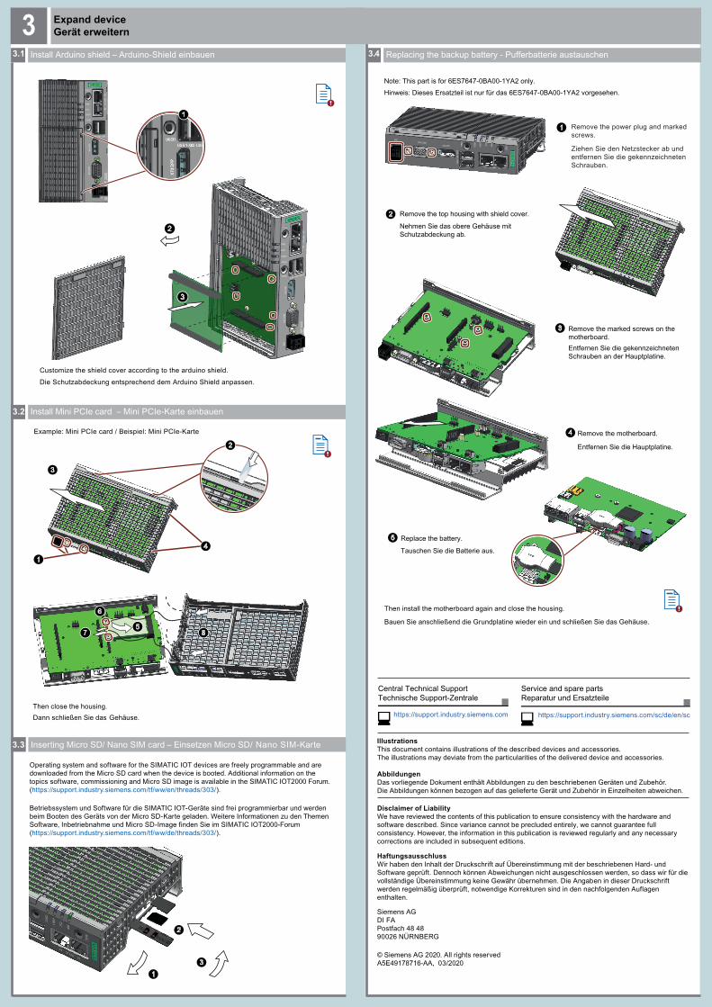
Inserting Micro SD/ Nano SIM card – Einsetzen Micro SD/ Nano SIM-Karte3.3
Betriebssystem und Software für die SIMATIC IOT-Geräte sind frei programmierbar und werden beim Booten des Geräts von der Micro SD-Karte geladen. Weitere Informationen zu den Themen Software, Inbetriebnahme und Micro SD-Image finden Sie im SIMATIC IOT2000-Forum(https://support.industry.siemens.com/tf/ww/de/threads/303/).
Operating system and software for the SIMATIC IOT devices are freely programmable and are downloaded from the Micro SD card when the device is booted. Additional information on thetopics software, commissioning and Micro SD image is available in the SIMATIC IOT2000 Forum. (https://support.industry.siemens.com/tf/ww/en/threads/303/).
4
3Expand deviceGerät erweitern3
Replacing the backup battery - Pufferbatterie austauschen
3.2 Install Mini PCIe card – Mini PCIe-Karte einbauen
3.1 Install Arduino shield – Arduino-Shield einbauen
1
2
3
RESTREST
1
Customize the shield cover according to the arduino shield.
5
6
7
Example: Mini PCIe card / Beispiel: Mini PCIe-Karte
Then close the housing.Dann schließen Sie das Gehäuse.
3
1
4
2
8
2
3
Die Schutzabdeckung entsprechend dem Arduino Shield anpassen.
1
2 Remove the top housing with shield cover.
Note: This part is for 6ES7647-0BA00-1YA2 only.Hinweis: Dieses Ersatzteil ist nur für das 6ES7647-0BA00-1YA2 vorgesehen.
Remove the power plug and marked screws.
Ziehen Sie den Netzstecker ab und entfernen Sie die gekennzeichneten Schrauben.
Nehmen Sie das obere Gehäuse mit Schutzabdeckung ab.
Then install the motherboard again and close the housing.
Bauen Sie anschließend die Grundplatine wieder ein und schließen Sie das Gehäuse.
4
5
3 Remove the marked screws on the motherboard.
Replace the battery.
Remove the motherboard.
Entfernen Sie die gekennzeichneten Schrauben an der Hauptplatine.
Entfernen Sie die Hauptplatine.
Tauschen Sie die Batterie aus.