2002 honda odyssey tsb all
TRANSCRIPT
8/2/2019 2002 Honda Odyssey TSB All
http://slidepdf.com/reader/full/2002-honda-odyssey-tsb-all 1/38
Service Bulletin 01-009I- : · ]Applies To: 1998-02 Accord V6 - ALL
1999-02 Odyssey - ALL
August 14, 2001
V6 Engine Oil Leaks(Supersedes 01-009, Accord V6 Engine Oil Leaks, dated January 16, 2001)
SYMPTOM
An oil leak Irom the front, middle, or rear of the engine.
PROBABLE CAUSE
The cast aluminum engine block may be porous at the
fronl, middle, or rear.
CORRECTIVE ACTION
Depending on Ihe location of the leak, seal it with JB
Weld or with 3-Bond-coated sealing bolts.
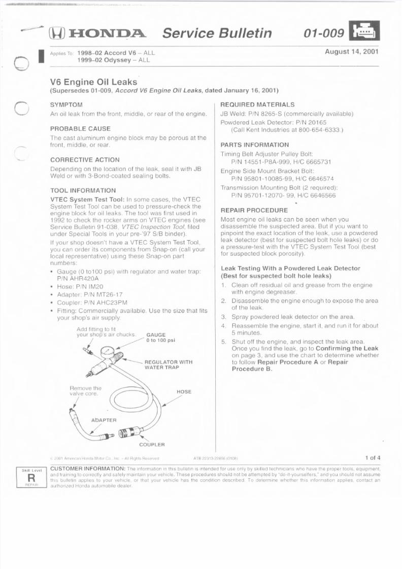
TOOL INFORMATIONVTEC System Test Tool: In some cases, the VTEC
System Test Tool can be used to pressure-check theengine block for oil leaks The tool was first used in
1992 to check the rocker arms on VTEC engines (see
Service BuIIetin 91-038, VTEC Inspection Tool. fiIed
under Special Tools in your pre-'97 SIB binder).
II your shop doesn't have a VTEC System Test Tool,
you can order its components from Snap-on (call your
local representative) using these Snap-on part
numbers:
• Gauge (0 to100 psi) with regulator and water trap:
PIN AHR420A
• Hose: PIN IM20• Adapter: PIN MT26-17
• Coupler: PIN AHC23PM
• Fitting: Commercially available. Use the size that fits
your shop's air supply,
_______ REGULATOR WITH
WATER TRAP
Remove the
valve core.I~ Ab~PTER!
~
HOSE-:
REQUIRED MATERIALS
JB Weld: PIN 8265-8 (commercially available)
Powdered Leak Detector' PIN 20165
(Call Kent Industries at 800-654-6333,)
COUPLER
PARTS INFORMATION
Timing Bell Adjuster Pulley 801t :
PIN 14551-P8A-999, H/C 6665731
Engine Side Mount Bracket Boll:
PIN 95801-10085-99, HIC 6646574
Transmission Mounting Bolt (2 required):
PIN 95701-12070- 99, Hie 6646566
REPA.IH PHOCEDURE
Most engine oil leaks can be seen when you
disassemble the suspected area. But il you want to
pinpoint the exact location of the leak, use a powdered
leak detector (best lor suspected bolt hole leaks) or doa pressure-test with the VTEC System Test Tool (best
for suspected block porosity)
Leak Testing With a Powdered Leak Detector
(Best for suspected bolt hole leaks)
1, Clean ofl residual oil and grease from the enginewith engine degreaser.
2. Disassemble the engine enough to expose the area
of the leak.
3. Spray powdered leak detector on the area.
4. Reassemble the engine, start it, and run it for about
5 minutes.
5, Shut off Ihe engine, and inspect the leak area.
Once you lind the leak, go to Confirming the Leak
on page 3, and use the chart 10 determine whether
to follow Repair Procedure A or Hepair
Procedure B.
A TR 2 ~ 31 3- 22 8; :6 10 10 8.1 1 of
R
CUSTOMER INFORMATION: The information in this bullet in is intended tor use only by skilled technicians who have Ihe proper tools, equipmen
and training 10correctly and safely maintain your vehicle. These procedures should nOIbe arternptec by "do-rt-yourselters." and you :ihould nOIassum
IIlIs bulleti II applies 10 your veh icte, or rnaI you r verucle has Ihe cond il ion described. To delerm ine whelhe r this inforrnat ion apph es, contact aauthorized Honda aulomobile daaler.
Skill Level
8/2/2019 2002 Honda Odyssey TSB All
http://slidepdf.com/reader/full/2002-honda-odyssey-tsb-all 2/38
Leak Testing With the VTEC System Test Tool
(Best for suspected block porosity)
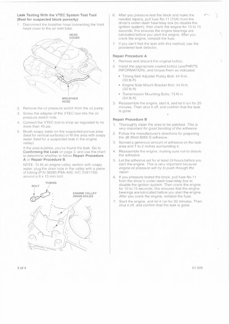
1_ Disconnect the breather hose connecting the front
head cover to the air inlet tube
BREATHER
HOSE
2. Remove the oil pressure switch from the oil pump3 Screw the adapter of the VTEC tool into the oil
pressure switch hole.
4. Connect the VTEC tool to shop air regulated to no
more than 40 psi.
5_ Brush soapy water on the suspected porous area(best for vertical surfaces) or fill the area with soapy
water (best lor a suspected leak in tile engine
valley)
If the area bubbles, you've found the leak. Go to
Confirming the Leak on page 3, and use the chart
to determine whether 10 follow Repair Procedure
A or Repair Procedure B.
NOTE' To fill an engine valley section with soapywater, plug the drain hole in the valley with a piece
of tubing (P/N 36285-P8A-AOO, H/e 5181730)
around a 6 x 15 mm bolt.
ENGINE VALLEYDRAIN HOLES
2 of 4
6. After you pressure-test the block and make the ~
needed repairs, pull fuse No 11 (1SA) from the
driver's under-dash fuse/relay box (to disable the
ignition system), then crank Ihe engine for 10 to 15
seconds; this ensures the engine bearings are
lubricated before you start the engine. After you
crank the engine, reinstall the tuse.
7. If you can't find the leak with this method, use the
powdered leak detector.
Repair Procedure A
1. Remove and discard the original bolt{s).
2. Install the appropriate coated bolt(s) (seePARTS
INFORMATION), and torque them as indicated:
• Timing Belt Adjuster Pulley Bolt: 44 Nm
(33 Ib-It)
• Engine Side Mount Bracket Bolt: 44 N-m
(33Ib-ft)
• Transmission Mounting Bolts: 73 N m
(54Ib-ft)
3_ Reassemble Hie engine, start it, and let it run for 20
minutes. Then shut it off, and confirm that the leak
is gone.
Repair Procedure B
1. Thoroughly clean the area to be patched. This is
very important for good bonding of the adhesive.
2. Follow the manufacturer's directions for preparing
the JB Weld 8265-S adhesive.
3. Spread a generous amount of adhesive on the leak
area and 1 to 2 inches surrounding it.
4. Reassemble the engine, making sure not to disturb
the adhesive.
5_ Let the adhesive set for at least 24 hours before you
start the engine. This is very important becauseengine oil pressure will try to push through the
repair.
6. If you pressure-tested the block, pull fuse No.l1
from the driver's under-dash fuse/relay box to
disable the ignition system. Then crank the engine
for 10 to 15 seconds; this ensures that the engine
bearings are lubricated before you start the engine.
After you crank the engine, reinstall the fuse.
7_ Start the engine, and Ie! it run for 20 minutes. Then
shut it off, and confirm that the leak is gone_
01-009
8/2/2019 2002 Honda Odyssey TSB All
http://slidepdf.com/reader/full/2002-honda-odyssey-tsb-all 3/38
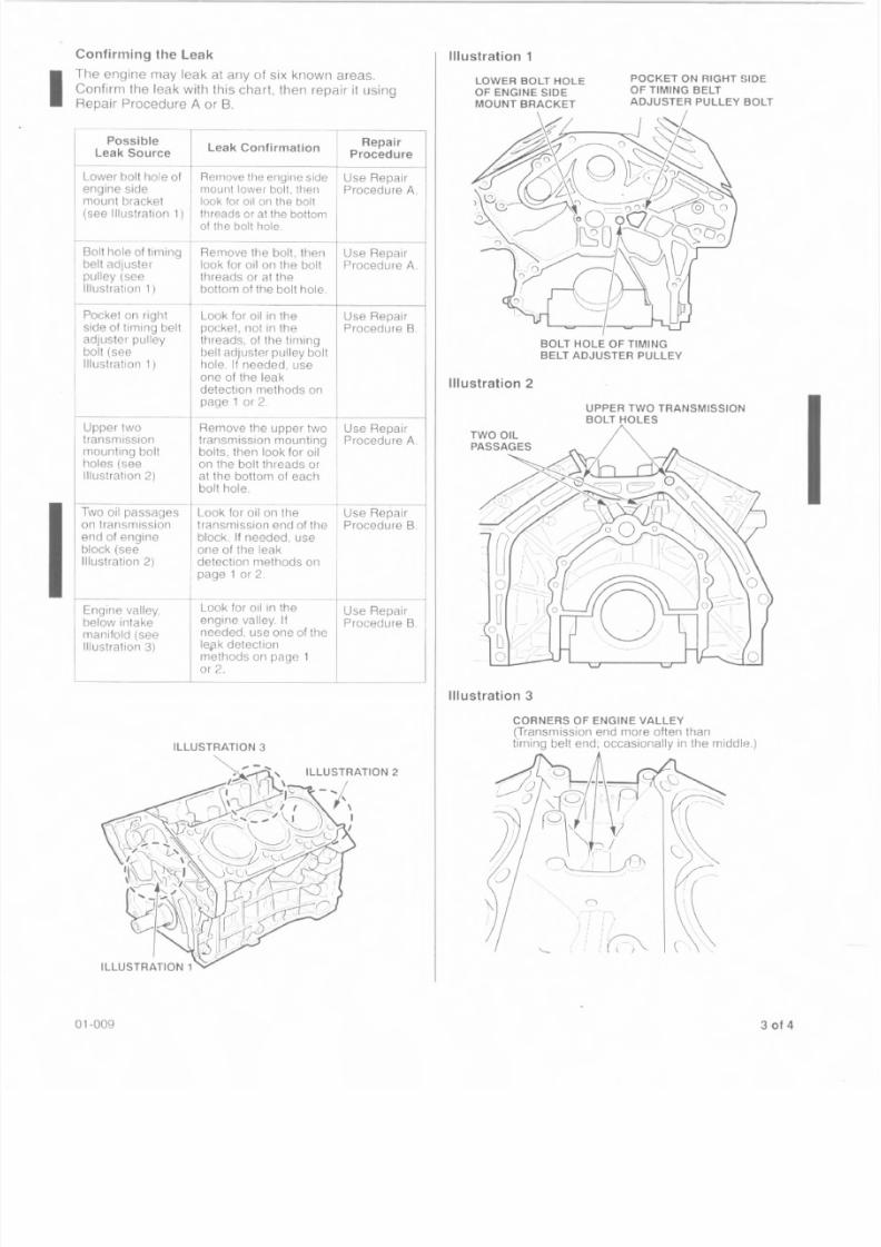
Confirming the Leak
Ihe engine may leak at any of six known areas.
. Confirm the leak with this chart, then repair it usingRepair Procedure A or B.
PossibleLeakSource
Lower bolt hole ofengine sidemount bracket
(see lliustrat ion 1) , I
Bolt hole of timingbelt adjusterpulley (seeIllustration 1)
Pocket on riglltside 01 timing beltadjuster pulleybolt (seeIllustration 1)
Upper twotransmissionmounting boltholes (seeIllustration 2)
Two oil passageson transmissionend of engineblock (seeIllustration 2)
Leak ConfirmationRepair
Procedure
Remove tile engine sidemount lower bolt. thenlook for oi l on the bollthreads or at the bottomof the bolt hole.
Use RepairProcedure A .
Use RepairProcedure A .
Remove the bolt, thenlook lor oil on the boltthreads or at thebottom of the bolt hole,
Look lor oil in the Use Repairpocket, not in the Procedure B.threads. 01 the timingbelt adjuster pulley bolthole. If needed, useone of the leakdetection methods onpage 1 or 2.
Remove the upper two Use Repairtransmission mounting Procedure A .
bolts, then look for oilon the bolt threads orat the bottom of eachbolt hole.
Look for oil on the Use Repairtransmission end of the Procedure B .block. If needed, useone of the leakdetection methods onpage 1 or 2
Engine valley,below intakemanifold (seeIllustration 3)
Look lor oil In the Use Repairengine valley. If Procedure B.
needed, use one of theleflk detectionmelhods 011 page 1
or 2.
01-009
ILLUSTRATION 2
Illustration 1
LOWER BOLT HOLE
OF ENGINE SIDE
MOUNT BRACKET
POCKET ON RIGHT SIDE
OF TIMING BELT
ADJUSTER PULLEY BOLT
BOLT HOLE OF TIMING
BELT ADJUSTER PULLEY
Illustration 2
IIIustration 3
CORNERS OF ENGINE VALLEY
(Transmission end more often thanliming belt end: occasionally in the rniddle.)
n.' r
i I \
1 , 1 I
.: 1r?0 -I I __
, 'I '
:. ' . l I
3014
8/2/2019 2002 Honda Odyssey TSB All
http://slidepdf.com/reader/full/2002-honda-odyssey-tsb-all 4/38
Description FR~
d: Repair pulley bOltll_o_le_o_f-+_3-7bell adjuster (includes
the leak)
d: Repair pocket on right 4.0
timing belt adjuster pulley
e (includes finding the leak,
Weld setup procedure):--:------:-----:,-f----=----1
d: Repair lower bolt hole of OJ
gine side mount bracket
es finding the leak)--
d: Repair upper two
ssion mounting bolt holes
es finding the leak)---
d: Repair engine valley
ntake manifold (includes
the leak, and JB Weld setup
ure)
d: Repair two oil passages 7_3
smission end of engine
ncludes finding the leak,Weld setup procedure)
109001 Odyssey: Repair pulley bolt hole 3_ 7
of timing belt adjuster (includes
finding the leak)---
109002 Ody ssey: Re pa ir pocke t on rig ht 4.0
side of liming belt adjuster pulley
boll hole (includes finding the leak,
and J8 Weld setup procedure)__---j---
109003 Odyssey: Repair lower bolt hole of
the engine side mount bracket
(includes finding the leak)
109004 Odyssey: Repair upper two
transmission mounting bolt holes
(includes finding the leak)
Odyssey: Repair engine valley
, below intake manifold (includes
finding the leak. and J8 Weld setup
procedure)---+ _---_ ------j
109006 Odyssey: Repair two oit passages
on transmission end of engine
block (includes finding the leak,
and JB Weld setup procedure)__ -L
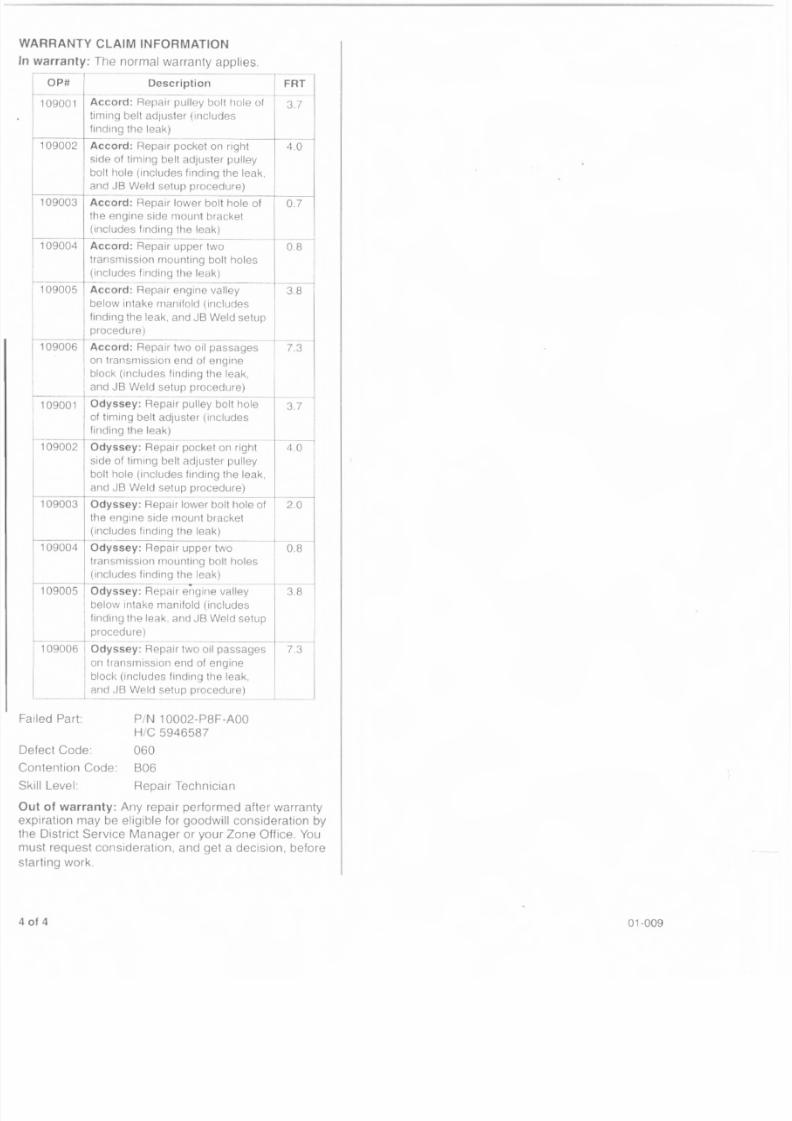
RRANTY CLAIM INFORMATION
warranty: The normal warranty applies.
OP#I
.109001 Accor
timing
finding
109002 Accor
side of
boll hal
and JB109003 Accor
the en
(includ-- -1--._-
109004 Accor
transmi
(includ
109005 Accor
below i
finding
proced
109006 I Accor
on tran
Iblock (iand JBt--
--
0.8
3.8
led Part: PIN 10002-P8F-AOQ
HIC 5946587
fect Code: 060ntention Code: B06
ll Level: Repair Technician
t of warranty: Any repair performed after warranty
iration may be eligible for goodwill consideration by
District Service Manager 01' your Zone Office. You
st request consideration. and get a decision. before
ting work.
3.8
J
01-009
8/2/2019 2002 Honda Odyssey TSB All
http://slidepdf.com/reader/full/2002-honda-odyssey-tsb-all 5/38
lH J :HO:ND.A Service Bulletin 01-012~
Applies To 1996-97 Accord L4 - ALL with AlT
1996-97 Odyssey - ALL
May 15, 2001
MIL Comes On With Arr DTC P0715
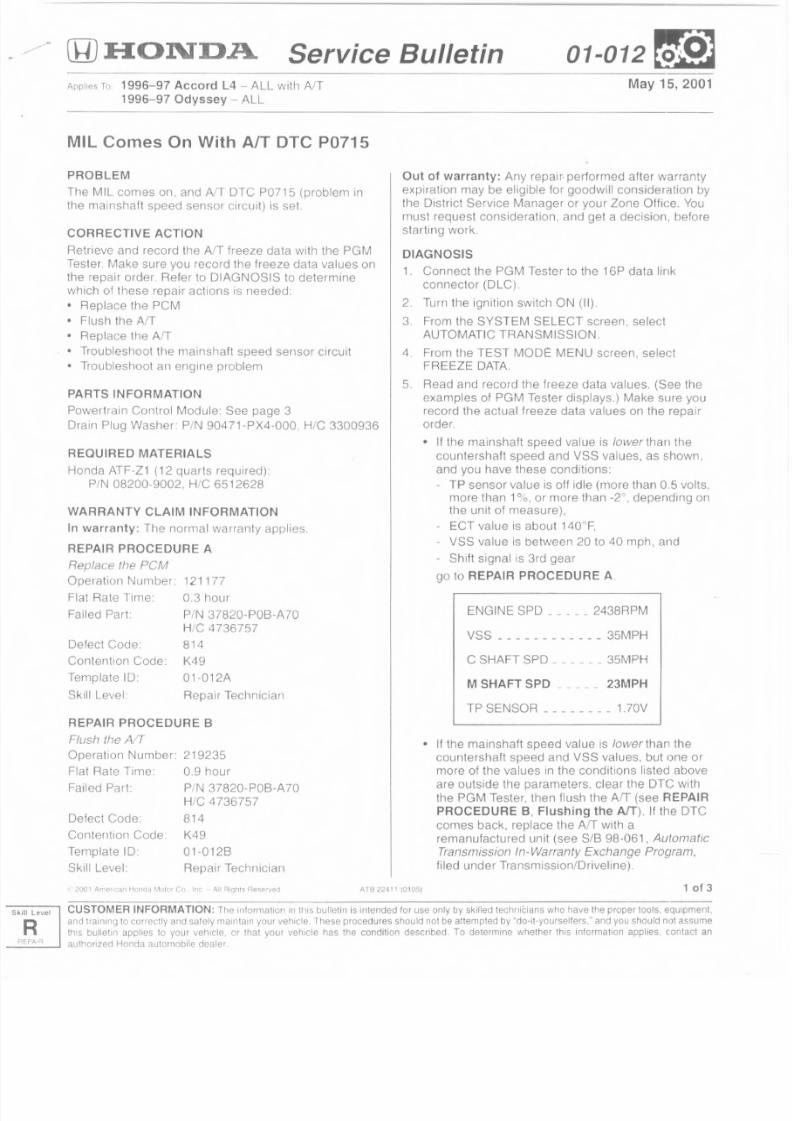
PROBLEM
The MIL comes on, and AlT OTG P0715 (problem inthe mainshaft speed sensor circuit) is set.
CORRECTIVE ACTION
Retrieve and record the A/T freeze data with the PGM
Tester, Make sure you record the freeze data values on
the repair order, Refer to DIAGNOSIS to determine
which of these repair actions is needed:
• Replace the PCM
• Flush the AIT
• Replace the AfT
• Troubleshoot the mainshaft speed sensor circuit
• Troubleshoot an engine problem
PARTS INFORMATION
Powertrain Control Module: See page 3
Drain Plug Washer: PIN 90471-PX4-000, HIC 3300936
REQUIRED MATERIALS
Honda ATF-Z1 (12 quarts required)
PIN 08200-9002, HIC 6512628
WARRANTY CLAIM INFORMATION
In warranty: The normal warranty applies.
REPAIR PROCEDURE A
Replace the PCMOperation Number: 121177
Flat Rate Time 0.3 hour
Failed Part PIN 37820-P08-A 70
H/C 4736757
Defect Code: 814
Contention Code:
Template ID:
Skill Level
K49
01-012A
Repair Technician
REPAIR PROCEDURE 8
Flush the AIT
Operation Number: 219235Flat Rate Time: 0.9 hour
Failed Part: PiN 37820-POB-A70
HIC 4736757
Defect Code: 814
Contention Code K49
Template 10: 01-0128
Skill Level: Repair Technician
ArB 22,11 ' {0105)
Out of warranty: Any repair, performed after warranty
expiration may be eligible for goodwill consideration bythe District Service Manager or your Zone Office. You
must request consideration, and get a decision, before
starting work,
DIAGNOSIS
1, Connect the PGM Tester to the 16P data link
connector (DLC),
2. Turn the ignition switch ON (II).
3, From the SYSTEM SELECT screen, select
AUTOMATIC TRANSMISSION,
4. From the TEST MOOt: MENU screen, selectFREEZE DATA.
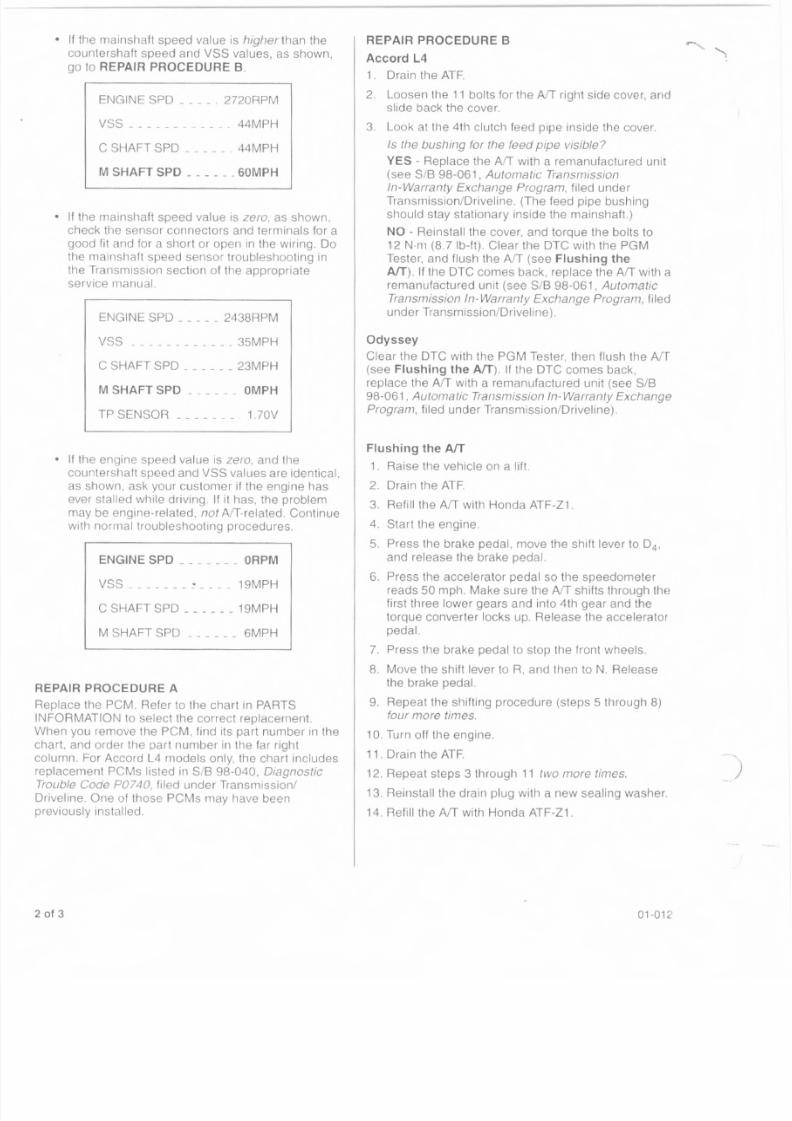
5. Read and record tile freeze data values. (See the
examples of PGM Tester displays.) Make sure yourecord the actual freeze data values on the repairorder,
• II the mainshalt speed value is lower than the
counlershaft speed and VSS values, as shown.
and you have these conditions:
- TP sensor value is off idle (more than 0.5 volts.more than 1%. or more than -2°, depending onthe unit of measure).
- ECT value is about 140°F,
- VSS value is between 20 to 40 mph, and
- Shift signal is 3rd gear
go to REPAIR PROCEDURE A.
ENGINE SPD 2438RPM
VSS 35MPH
C SHAFT SPO 35MPH
M SHAFT SPD 23MPH
TP SENSOR 1.70V
• II the mains haft speed value is lower than the
countershalt speed and VSS values, but one ormore of the values in the conditions listed above
are outside the parameters, clear the OTC with
the PGM Tesler. then flush the Arr (see REPAIR
PROCEDURE B, Flushing the AfT). II the OTC
comes back, replace the AfT with a
remanufactured unit (see SIB 98-061. Automatic
Transmission In-Warranty Exchange Program,
filed under Transmission/Oriveline),
1 of 3
-vel CUSTOMER INFORMATION: The information In this bulletin is intended lor use only by skilled technicians who have the proper tools. equipment,
and training to correctly and safely maintain your vehicle. These procedures should not be attempted by "do-tt-yourselters." and you should not assume
llus bulletin applies to your vehicle, or that your vehicle has the condit ion descr ibed To determine whether this informat ion applies, contact an
authorized Honda automobile dealer
8/2/2019 2002 Honda Odyssey TSB All
http://slidepdf.com/reader/full/2002-honda-odyssey-tsb-all 6/38
• If the mainshaft speed value is higherthan the
counlershaft speed and VSS values, as shown,
go 10 REPAIR PROCEDURE B.
ENGINE SPD . 2720RPM
VSS _ _ _ _ __ _ _ __ . 44MPH
C SHAFT SPD . 44MPH
M SHAFT SPD .60MPH
• If the mainshaft speed value is zero, as shown,
check the sensor connectors and terminals for agood fit and for a short or open in the wiring. Do
the rnainshalt speed sensor troubleshooting in
the Transmission section of the appropriate
service manual.
ENGINE SPD 2438RPM
VSS 35MPH
C SHAFT SPD 23MPH
M SHAFT SPO __ _ _ _ _ OMPH
TPSENSOR 1.70V
• If the engine speed value is zero, and the
countershaft speed and VSS values are identical,
as shown, ask your customer if the engine has
ever stalled while driving. If it has, the problem
may be engine-related, not AfT-related. Continue
with normal troubleshooting procedures.
ENGINE SPD ORPM
VSS ~ 19MPH
C SHAFT SPD 19MPH
M SHAFT SPD 6MPH
REPAIR PROCEDURE A
Replace the PCM. Refer· to the chart in PARTS
INFORMATION to select the correct replacement.
When you remove the PCM, lind its part number in the
chart, and order the part number in the far right
column. For Accord L4 models only, the chart includesreplacement PCMs listed in SIB 98-040, Diagnostic
Trouble Code P074G, filed under Transmissionl
Driveline. One of those PCMs may have beenpreviously installed.
2 of 3
REPAIR PROCEDURE B
Accord L4
1. Drain the ATF.
2 . Loosen the 11 bolts for the A fT right side cover, andslide back the cover.
3. Look at the 4th clutch feed pipe inside the cover.
Is the bushing for the feed pipe visible?
YES - Replace the AfT with a remanufactured unit
(see SIB 98-061, Automatic Trensrnission
In-Warranty Exchange Program, filed underTransmission/Driveline. (The feed pipe bushing
should stay stationary inside the mainshaft)
NO - Reinstall the cover, and torque the bolts to
12 Nrn (8.7 lb-tt). Clear the DTC with the PGM
Tester, and flush the AfT (see Flushing the
AfT). If the DTC comes back, replace the AfT with aremanufactured unit (see SIB 98-061, Automatic
Transmission In-Warranty Exchange Program, filed
under Transmission/Driveline).
Odyssey
Clear the DTC with the PGM Tester, then flush the NT(see Flushing the AfT). II the DTe comes back,
replace the AfT with a remanufactured unit (see SIB98-061, Automatic Transmission In-Warranty Exchange
Program, filed under Transmission/Driveline).
Flushing the AfT
1. Raise the vehicle on a lift
2. Drain the ATF
3. Refillihe AfT with Honda ATF-Z1.
4. Start the engine.
5. Press the brake pedal, move the shift lever to 04 ,
and release the brake pedal
6. Press the accelerator pedal so the speedometer
reads 50 mph. Make sure the A fT shifts through the
first three lower gears and into 4th gear and the
torque converter locks up. Release the accelerator
pedal.
7. Press the brake pedal to stop the front wheels.
8 Move the shitt lever to R, and then to N. Release
the brake pedal.
9. Repeat the shifting procedure (steps 5 through 8)
four more times.
10. Turn off the engine.
11. Drain the ATF.12. Repeal steps 3 through 11 two more times.
13. Reinstall the drain plug with a new sealing washer.
14. Refill the NT with Honda ATF-Z1.
01-012
)
8/2/2019 2002 Honda Odyssey TSB All
http://slidepdf.com/reader/full/2002-honda-odyssey-tsb-all 7/38
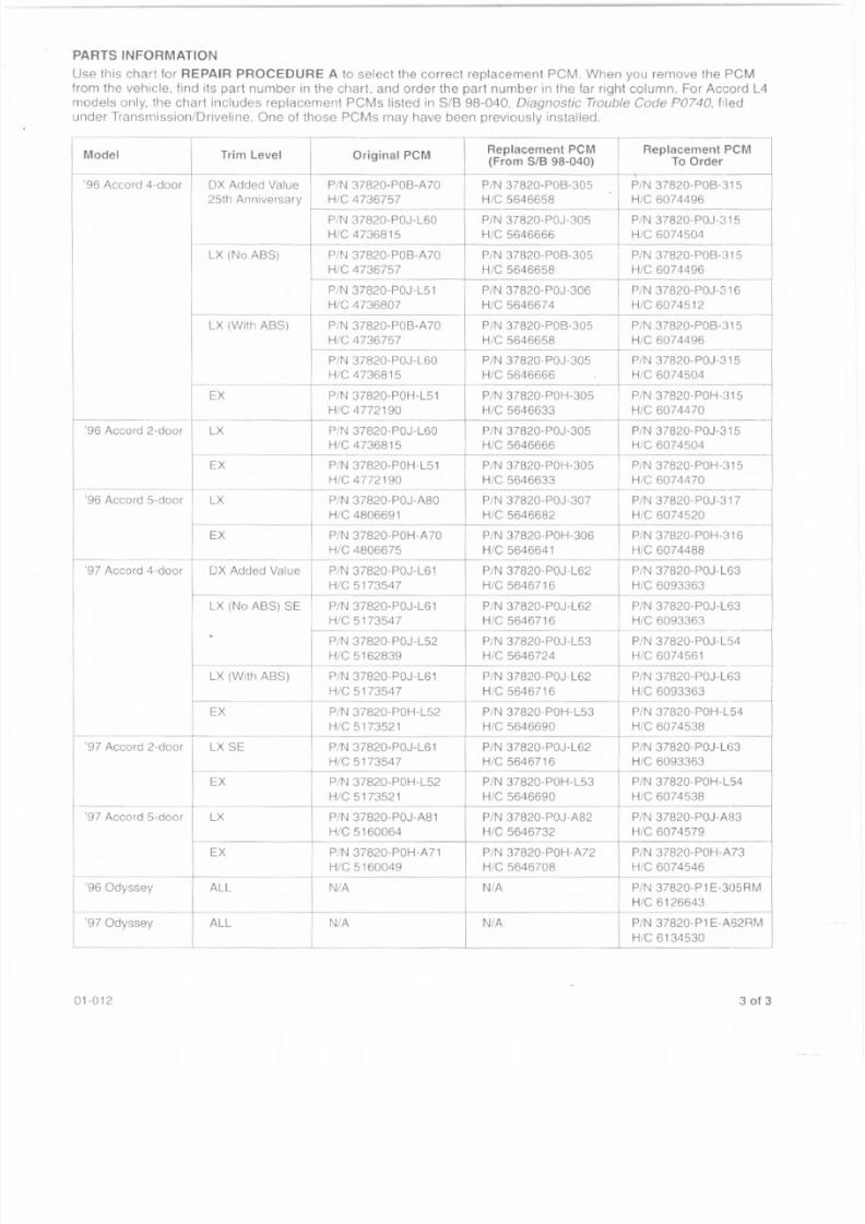
PARTS INFORMATION
Use this chart for REPAIR PROCEDURE A to select the correct replacement PCM. When you remove the PCM
from the vehicle, find its part number in the chart. and order the part number in the far right column. For Accord L4models only. the chart includes replacement PCMs listed in SIB 98-040, Diagnostic TroubleCode P0740. filed
under Transmission/Driveline. One of those PCMs may have been previously installed
Model Trim Level Original PCM
'96 Accord 4-door
'96 Accord 2-door
'96 Accord 5-door
OX Added Value
25th Anniversary
PIN 37820-POB-A70
Hie 4736757
PIN 37820-POJ-L60
Hie 4736815----+----
PIN 37820-POB-A70
Hie 4736757
PiN 37820-POJ-L51
Hie 4736807
LX (No ASS)
LX (With ASS)
Replacement peM(From SIB 98-040)
_ - - - - --,PIN 37820-POS-305
Hie 5646658
PIN 37820-POB-A70 PIN 37820-POB-305
Hie 4736757 Hie 5646658 Hie 6074496-r- ------+__
PIN 37820-POJ-L60 PIN 37820-POJ-305 PIN 37820- POJ-315
Hie 4736815 Hie 5646666 Hie 6074504-~--
PIN 37820-POH-315
Hie 6074470
PIN 37820-POH-L51
Hie 4772190--~---+-PIN 37820-POJ-L60
Hie 4736815
LX
LX (With ABS)
EX
LX SE97 Accord 2-uoor
'97 Accord 5-door
'96 Odyssey
'97 Odyssey
01-012
PIN 37820-POJ-305
Hie 5646666--
PIN 37820-POB-305
Hie 5646658
PIN 37820-POJ-306
Hie 5646674
PIN 37820-POH-305
HIe 5646633PIN 37820-POJ-305
Hie 5646666
EX--1---------- -
ALL NlA
ALL
PIN 37820- POJ·315
Hie 6074504
PiN 37820- POH·L51 PIN 37820· P0H-305 PIN 3782O·POH-315
Hie 4772190 Hie 5646633 HIe 6074470----+--- _--_~- _--_
PIN 37820-POJ-A80 PIN 37820-POJ·307 PIN 37820-POJ·317
Hie 4806691 Hie 5646682 Hie 6074520
PIN 37820- POH-A70 PIN 37820· POH-306 PiN 37820· POH-31 6
Hie 4806675 HIe 5646641 HIe 6074488-r-------+-- ------1-------'97 Accord 4-door ~X Added Value _t---_P/_N_3_7_8_2_O._P_0_J.L61PIN 37820-POJ-L62 PIN 37820·POJ·L63
Hie 5173547 Hie 564671 6 Hie 6093363------'-
X (No ASS) SE PIN 37820-POJ·L61 PIN 37820-POJ-L62 PIN 37820-POJ·L63
HIe 5173547 Hie 5646716 Hie 6093363
PIN 37820·POJ-L52 PIN 37820-PO.J·L53 PIN 37820-POJ-L54
Hie 5162839 HIe 5646724 Hie 607tJ561------+--- ------t-------
PIN 37820·POJ-L61 PIN 37820·POJ-L62 PIN 37820-POJ-L63
Hie 5173547 Hie 564671 6 Hie 6093363
PIN 37820-POH-L52 PIN 37820·POH-L53 PIN 37820-POH-L54
H/C 5173521 Hie 5646690 Hie 6074538----------------~-- --------~PIN 37820-POJ·L61 PIN 37820·POJ-L62 PIN 37820·POJ-L63
Hie 5173547 Hie 564671 6 Hie 6093363~----------------t--------------~
PIN 37820-POH·L52 PIN 37820·POH·L53 PIN 37820·POH-L54
Hie 5173521 Hie 5646690 Hie 6074538-----~-------------
PIN 37820-POJ·A81 PIN 37820·POJ-A82 PIN 37820·POJ·A83
Hie 5160064 Hie 5646732 H/C 6074579-----------~ ------~----------
PIN 37820-POH-A71 PIN 37820-POH-A72 PIN 37820-POH·A73
Hie 5160049 Hie 5646708 Hie 6074546
N/A
N/A N/A
Replacement PCM
To Order... --------i
PIN 37820-POB-315
Hie 6074496
PIN 37820-POJ·315
Hie 6074504
PIN 37820-POB<315
Hie 6074496
PiN 37820- POJ-316
HIe 6074512
PIN 37820-POB-315
PiN 37820-Pl E-A62RM
Hie 6134530
3 of 3
8/2/2019 2002 Honda Odyssey TSB All
http://slidepdf.com/reader/full/2002-honda-odyssey-tsb-all 8/38
Service Bulletin 01-020 [~1AppliesTo: 1999-01 Odyssey EX - ALL November 27, 2001
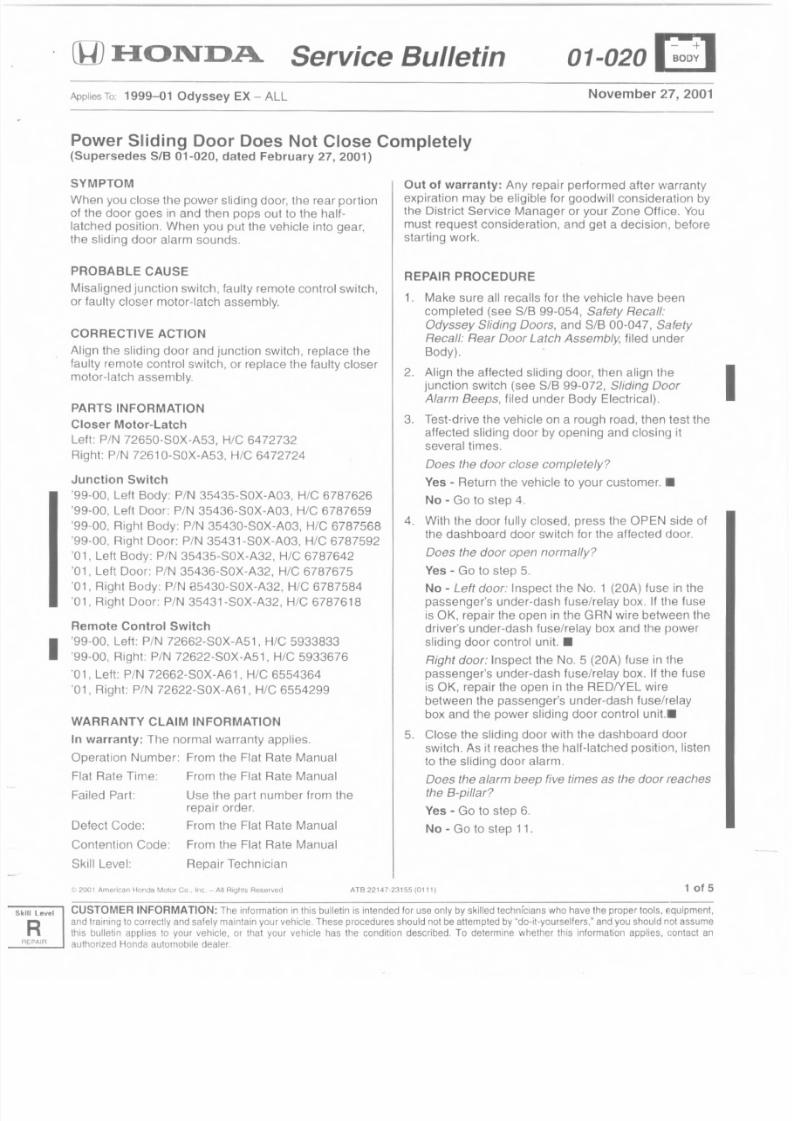
Power Sliding Door Does Not Close Completely(Supersedes SIB 01-020, dated February 27,2001)
SYMPTOMWhen you close the power sliding door, the rear portionof the door goes in and then pops out to the half-
latched position. When you put the vehicle into gear,the sliding door alarm sounds.
PROBABLE CAUSE
Misaligned junction switch, faulty remote control switch,
or faulty closer motor-latch assembly.
CORRECTIVE ACTION
Align the sliding door and junction switch, replace the
faulty remote control switch, or replace the faulty closer
motor-latch assembly.
PARTS INFORMATION
Closer Motor-Latch
Left: PIN 72650-S0X-A53, Hie 6472732
Right: PIN 72610-S0X-A53, Hie 6472724
Junction Switch
'99-00, Left Body: PIN 35435-S0X-A03, Hie 6787626
'99-00, Left Door: PIN 35436-S0X-A03, H/C 6787659
'99-00, Right Body: PIN 35430-S0X-A03, Hie 6787568
'99-00, Right Door: PIN 35431-S0X-A03, Hie 6787592
'01, Left Body: PIN 3543S-S0X-A32, Hie 6787642
'01, Lett Door: PIN 35436-S0X-A32, H/e 6787675
'01, Right Body: PIN f3S430-S0X-A32, Hie 6787584
'01, Right Door: PIN 35431-S0X-A32, Hie 6787618
Remote Control Switch
I99-00, Lett: PIN 72662-S0X-AS1, H/C 5933833
'99-00, Right: PIN 72622-S0X-AS1, Hie 5933676
'01, Left: PIN 72662-S0X-A61, Hie 6554364
'01, Right: PIN 72622-S0X-A61 , Hie 6554299
WARRANTY CLAIM INFORMATION
In warranty: The normal warranty applies.
Operation Number: From the Flat Rate Manual
Flat Rate Time: From the Flat Rate Manual
Failed Part: Use the part number from therepair order.
Defect Code: From the Flat Rate Manual
Contention Code: From the Flat Rate Manual
Skill Level: Repair Technician
( '12001 American Honda Motor Co" Inc, - All Rights Resorvad
Out of warranty: Any repair performed after warrantyexpiration may be eligible for goodwill consideration bythe District Service Manager or your Zone Office. You
must request consideration, and get a decision, before
starting work.
REPAIR PROCEDURE
1 . Make sure all recalls for the vehicle have been
completed (see SIB 99-054, Safety Recall:
Odyssey Sliding Doors, and SIB 00-047, Safety
Recall: Rear Door Latch Assembly, filed under
Body).
2. Align the affected sliding door, then align the
Iunction switch (see SIB 99-072, Sliding Door
A/arm Beeps, filed under Body Electrical).
3. Test-drive the vehicle on a rough road, then test the
affected sliding door by opening and closing it
several times.
Does the door close completely?
Yes - Return the vehicle to your customer .•
No - Go to step 4.
4. With the door fully closed, press the OPEN side of
the dashboard door switch for the affected door.
Does the door open normally?
Yes - Go to step 5.
No - Left door: Inspect the NO.1 (20A) fuse in the
passenger's under-dash fuse/relay box. If the fuse
is OK, repair the open in the GRN wire between the
driver's under-dash fuse/relay box and the power
Sliding door control unit. •
Right door: Inspect the NO.5 (20A) fuse in the
passenger's under-dash fuse/relay box. If the fuse
is OK, repair the open in the REDIYEL wire
between the passenger's under-dash fuse/relay
box and the power sliding door control unit..
5. Close the sliding door with the dashboard door
switch. As it reaches the half-latched position, l isten
to the sliding door alarm.
Does the alarm beep five times as the door reaches
the B-pillar?
Yes - Go to step 6.
No - Go to step 11.
1 of 5TB 22147-2315510111)
CUSTOMERINFORMATION:Tileinformationnthisbulletins intendedor useonlybyskilledechnicians whohavetheproperools,equipment,andtrainingocorrectlyaridsafelymaintainyourvehicle.Theseprocedureshouldnotbeattemptedy"do-it-yourselters," andyoushouldnotassumethis bulletin appliesto yourvehicle,or thatyourvehiclehasthe conditiondescribed.To determinewhetherthis informationapplies,contactan
authorizedHondaautomobileealer.
8/2/2019 2002 Honda Odyssey TSB All
http://slidepdf.com/reader/full/2002-honda-odyssey-tsb-all 9/38
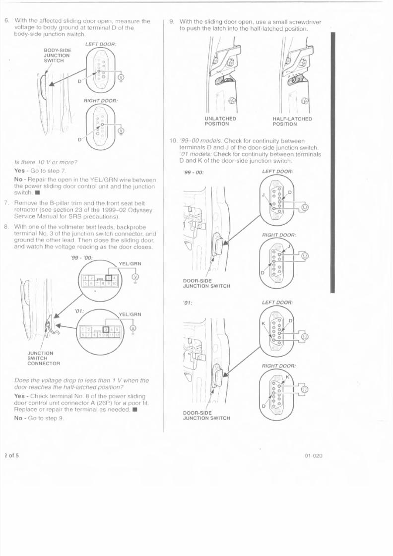
ith the affected sliding door open, measure the
oltage to body ground at terminal 0 of the
dy-side junction switch.
LEFT DOOR:
there 10 V or more?
es - Go to step 7.
o - Repair the open in the YEUGRN wire between
le power sliding door control unit and the junctiontch .•
emove the B-pillar trim and the front seat belt
etractor (see section 23 of the 1999-02 Odyssey
rvice Manual for SRS precautions).
ith one of the voltmeter test leads. backprobe
rminal No.3 of the junction switch connector, andround the other lead. Then close the Sliding door,
nd watch the voltage reading as the door closes.
JUNCTION
SWITCH
CONNECTOR
oes the voltage drop to less than 1 V when the
oor reaches the half-latched position?
es - Check terminal No.8 of the power Sliding
oor control unit connector A (26P) for a poor fil.eplace or repair the terminal as needed .•
o - Go to step 9.
9. With the Sliding door open, use a small screwdriver
to push the latch into the half-latched posit ion.
1 - ; I
I I G JI I
UNLATCHED
POSITIONHALF-LATCHED
POSITION
10 '99-00 modele: Check for continuity between
terminals 0 and J of the door-side junction switch.
'01 models: Check for continuity between terminals
o and K of the door-side junction switch
'99 - 00:
DOOR-SIDEJUNCTION SWITCH
'01:
LEFT DOOR:
RIGHTDDOR:
LEFT DOOR:
DOOR-SIDE
JUNCTION SWITCH
01-020
8/2/2019 2002 Honda Odyssey TSB All
http://slidepdf.com/reader/full/2002-honda-odyssey-tsb-all 10/38
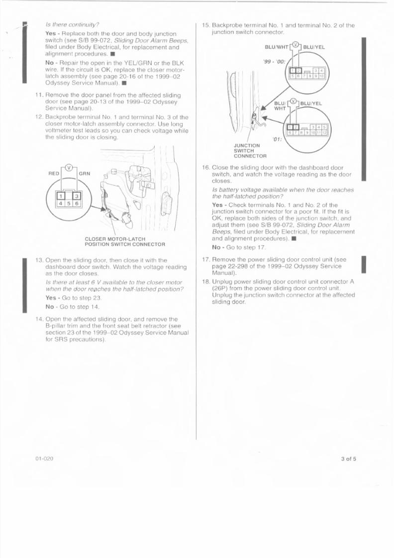
f! Is there continuity?
Yes - Replace both the door and body Junction
switch (see SIB 99-0.72, Sliding Door Alarm Beeps,
filed under Body Electrical, for replacement and
alignment procedures .•
No - Repair the open in the YEUGRN or the BLK
wire. If the circuit is OK, replace the closer motor-
latch assembly (see page 20.-16 01 the 1999-0.2Odyssey Service Manual) .•
11. Remove the door panel from the affected slidingdoor (see page 20.-13 of the 1999-0.2 OdysseyService Manual).
12. 8ackprobe terminal No.1 and terminal NO.3 of the
closer motor-latch assembly connector. Use long
voltmeter test leads so you can check voltage whilethe sliding door is closing.
CLOSER MOTOR-LATCH
POSITION SWITCH CONNECTOR
13. Open the sliding door, then close it with the
dashboard door switch. Watch the voltage reading
as the door closes.
Is there at least 6 V available to the closer motorwhen the door reecnes the half-latched position?
Yes - Go to step 23.
No - Go to step 14.
14. Open the affected sliding door, and remove the
B-pillar trim and the front seat belt retractor (see
section 23 of the 1999-0.2 Odyssey Service Manual
for SRS precautions).
01-020
15. Backprobe terminal No.1 and terminal No.2 of the
junction switch connector.
BLUIWHT
JUNCTIONSWITCH
CONNECTOR
16. Close the Sliding door with the dashboard door
switch, and watch the voltage reading as the door
closes.
Is battery voltage available when the door reachesthe half-latched position?
Yes - Check terminals No.1 and No.2 of thejunction switch connector for a poor fil. If the fit is
OK, replace both sides 01 the junction switch, and
adjust them (see SIB 99-072, Sliding Door Alarm
Beeps, f iled under Body Electrical, for replacement
and alignment procedures) .•
No - Go to step 17.
17. Remove the power sliding door control unit (see
page 22-298 of the 1999-02 Odyssey Service
Manual).
18. Unplug power sliding door control unit connector A(26P) from the power sliding door control unit.
Unplug the junction switch connector at the affected
sliding door.
3 of 5
I
8/2/2019 2002 Honda Odyssey TSB All
http://slidepdf.com/reader/full/2002-honda-odyssey-tsb-all 11/38
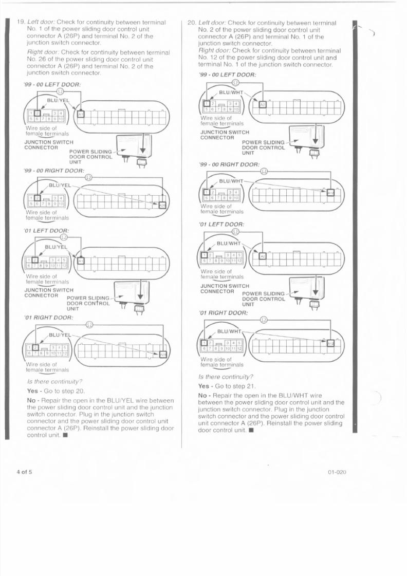
19. Left door: Check lor continuity between terminal
No.1 01the power sliding door control unit
connector A (26P) and terminal No.2 of the
junction switch connector.
Right door: Check for continuity between terminal
No. 26 of the power sliding door control unit
connector A (26P) and terminal No.2 01 thejunction switch connector.
'99 - 00 LEFT DOOR:
'99 - 00 RIGHT DOOR:
--01 LEFT DOOR:
'01 RIGHT DOOR:
Is there continuity?
Yes - Go to step 20.
No -Repair the open in the BLUfYEL wire between
the power sliding door control unit and the junction
switch connector. Plug in the junction switch
connector and the power sliding door control unit
connector A (26P). Reinstall the power sliding door
control unit. •
of 5
20. Left door: Check for continuity between terminal
No.2 of the power Sliding door control unitconnector A (26P) and terminal No.1 of the
junction switch connector.
Right door: Check for continuity between terminal
No. 12 of the power sliding door control unit and
terminal NO.1 of the junction switch connector.
'99 - 00 LEFT DOOR:
JUNCTION SWITCH ( , )1r(il~CONNECTOR . ; 1 1 1
POWER SLIDING - t : : " ' " " <,_.1
DOOR CONTROL T T ' c l i i lUNIT "fT"
'99 - 00 RIGHT DOOR:
~----------~{·H---------------.
'01 LEFT DOOR:
Is there continuity?
Yes - Go to step 21.
No - Repair the open in the BLUIWHT wire
between the power sliding door control unit and the
junction switch connector. Plug in the junction
switch connector and the power sliding door control
unit connector A (26P). Reinstall the power sliding
door control unit. •
01-020
8/2/2019 2002 Honda Odyssey TSB All
http://slidepdf.com/reader/full/2002-honda-odyssey-tsb-all 12/38
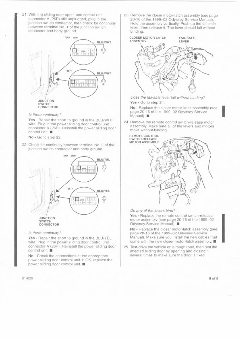
21. With the sliding door open, and control unit
connector A (26P) still unplugged, plug in the
junction switch connector, then check for continuitybetween terminal NO.1 of the junction switchconnector and body ground.
I, I I.,I I
. . . _ : ; ? , I
'I ' I I I, I I
I I ", ,
\ .'.
Is there continuity?
Yes ~Repair the short to ground in the BLU/WHTwire. Plug in the power sliding door control unit
connector A (26P), Reinstall the power sliding doorcontrol unit. •
No ~Go to step 22.
22. Check for continuity between terminal No.2 of the
junction switch connector and body ground.
\ , ' 1 ' , 1"~/
I , '1 '
i I I II
i I I I
1 '1
, I ,' , ' , ' / . / ; T
" ,
\ ...
. . . . \I",
_ . - . - < , . . ../
JUNCTION
SWITCH
CONNECTOR
Is there continuity?
Yes ~Repair the short to ground in the BLU/YEL
wire, Plug in the power sliding door control unit
connector A (26P).Reinstall the power sliding door
control unit. •
No ~Check the connections at the appropriate
power sliding door control unit. If OK, replace the
power sliding door control unit. •
01-020
23. Remove the closer motor-latch assembly (see page
20-16 of the 1999-02 Odyssey Service Manual).
Hold the assembly vertically. Push up the fail-safe
lever, then release it The lever should fall withoutbinding.
CLOSER MOTOR-LATCH
ASSEMBLY
\ u~ ,1-"<Gff_ "
Does the fail-safe lever fall without binding?
Yes - Go to step 24.
No - Replace the closer motor-latch assembly (see Ipage 20-16 of the 1999-02 Odyssey Service
Manual).. ...
24. Remove the remote control switch-release motorassembly. Make sure all of the levers and motorsmove without binding.
REMOTE CONTROL
SWITC H-RELEAS E
MOTOR ASSEMBLY
00 any of the levers bind?
Yes - Replace the remote control switch-release
motor assembly (see page 20-16 of the 1999-02
Odyssey Service Manual) .•
No- Replace the closer motor-latch assembly (seepage 20-16 of the 1999-0.2 Odyssey Service
Manual). Make sure you install the new cables that
come with the new closer motor-latch assembly .•
25. Test-drive tile vehicle on a rough road, then test the
affected sliding door by opening and closing it
several times to make sure the door is fixed.
5 of 5
8/2/2019 2002 Honda Odyssey TSB All
http://slidepdf.com/reader/full/2002-honda-odyssey-tsb-all 13/38
••
•
Service BulletinApplies To: 1999-2001 Odyssey - ALL May 8, 200
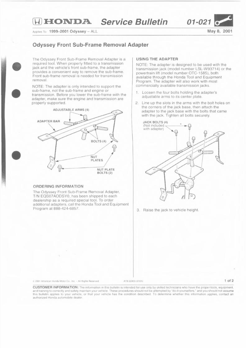
Odyssey Front Sub-Frame Removal Adapter
The Odyssey Front Sub-Frame Removal Adapter is arequired tool. When properly fitted to a transmission
jack and the vehicle's front sub-frame, the adapter
provides a convenient way to remove the sub-frame.Front sub-frame removal is needed for transmission
removal.
NOTE: The adapter is only intended to support the
sub-frame, not the sub-frame and engine or
transmission. Before you lower the sub-frame with the
adapter, make sure the engine and transmission are
properly supported.
ORDERING INFORMATION
The Odyssey Front Sub-Frame Removal Adapter,
TIN EOS07AODSYO,.has been shipped to each
dealership as a required special tool. To orderadditional adapters, calilhe Honda Tool and Equipment
Program at 888-424-6857.
~ ; 200 1 A 111mica n He nda MolD r C o , I nc, - A ll RIghts R es e r ve d AT6 22~ 55 (0105)
USING THE ADAPTER
NOTE: The adapter is designed to be used with the
tran smission jack (model number LSL -W93714) 0 r the
powertrain lift (model number OTC-1585), both
available through the Honda Tool and Equipment
Program. The adapter will also work with most
commercially available transmission jacks.
1. Loosen the four bolts holding the adapter'sadjustable arms to its center plate.
2. line up the slots in the arms with the bolt holes onthe corners of the jack base, then attach the
adapter to the jack base with the bolts that came
with the jack. Tighten all bolts securely,
3. Raise the jack to vehicle height.
1 of
CUSTOMER INFORMATION: The information in this bulletin is intended for use only by skilled technicians who have the proper tools, equipme
and training to correctly and safely maintain your vehicle. These procedures should nOIbe atternptsdby "do-it-yourselters." and you Should not assum
this bulletin applies \0 your vehicle, or that your vehicle has the condition described. To determine whether this information applies, contactauthorized Honda automobile dealer.
8/2/2019 2002 Honda Odyssey TSB All
http://slidepdf.com/reader/full/2002-honda-odyssey-tsb-all 14/38
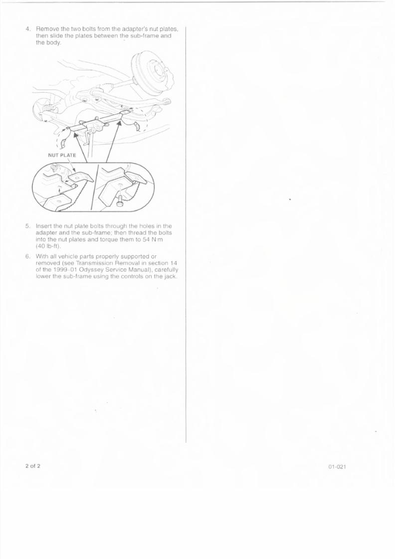
4. Remove the two bolts from the adapter's nut plates,
then slide the plates between the sub-frame andthe body. .
5. Insert the nut plate bolts through the holes in the
adapter and the sub-frame, then thread the bolts
into the nut plates and torque them to 54 N·m
(40Ib-ftl-
6. With all vehicle parts properly supported or
removed (see Transmission Removal in section 14
of the 1999 01 Odyssey Service Manual), carefully
lower the sub-frame using the controls on the jack.
2 of 2 01-021
8/2/2019 2002 Honda Odyssey TSB All
http://slidepdf.com/reader/full/2002-honda-odyssey-tsb-all 15/38
.(flJ E[ON"D.A. Service Bulletin 01-023r:.1
July 17, 2001\pplies In 2001 and Later Honda-Produced Vehicles With Programmable ECM/PCMs
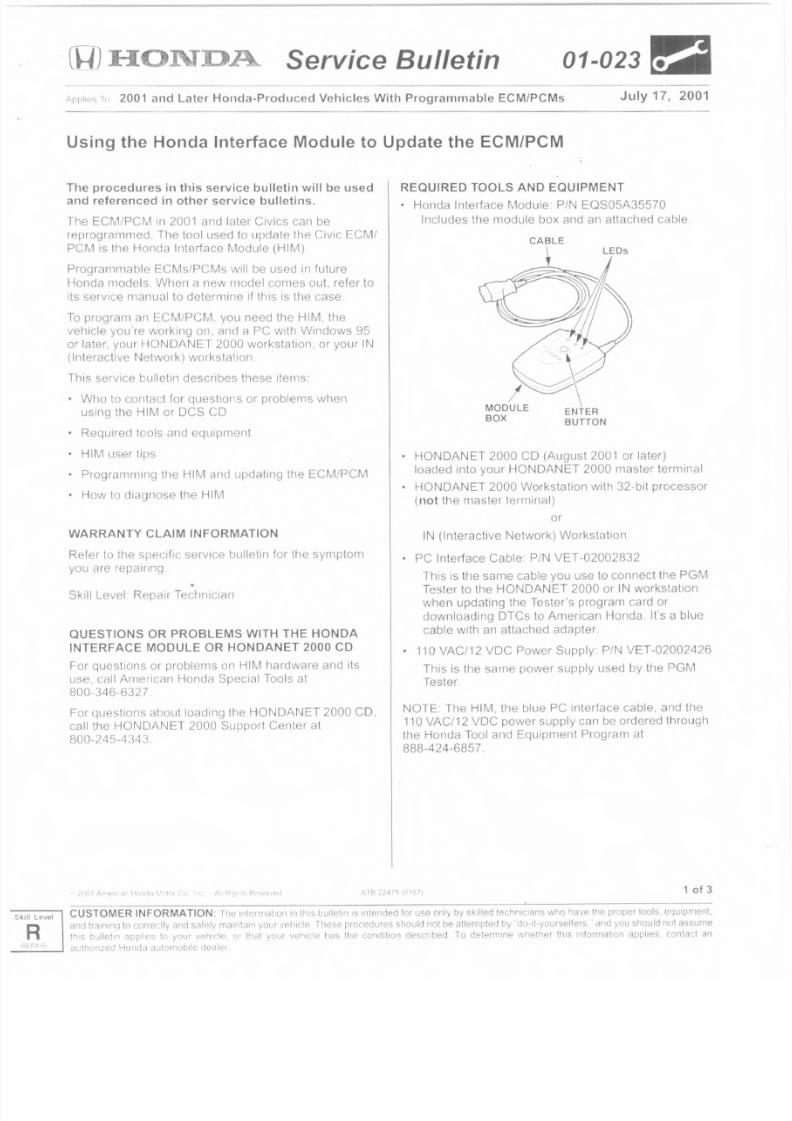
Using the Honda Interface Module to Update the ECM/PCM
The procedures in this service bulletin will be usedand referenced in other service bulletins.
The ECM(PCM in 2001 and later Civics can be
reprogrammed. The tool used to update the Civic ECMI
PCM is lhe Honda Interface Module (HIM)
Programmable ECMs/PCMs will be used in future
Honda models. When a new model comes out, refer to
its service manual 10 determine if this is the case.
To program an ECMJPCM, you need the HIM, Ihe
vehicle you're working on. and a PC with Windows 95
or later. your HONDANET 2000 workstation, or your IN
(Interactive Network) workstation.
This service bulletin describes these items:
Who to contact for questions or problems when
using the HIM or DCS CD
• Required tools and equipment
HIM user tips
• Programming the HIM and updating the ECM/PCM
• How to diagnose the HIM
WARRANTY CLAIM INFORMATION
Refer to the specif ic service bulletin for the symptom
you are repa iring.~
Skill Level: Repair Technician
QUESTIONS OR PROBLEMS WITH THE HONDA
INTERFACE MODULE OR HONDANET 2000 CD
For questions or problems on HIM hardware and its
use, call American Honda Special Tools at
800-346-6327.
For questions about loading the HONDANET 2000 CD,
call the HONDANET 2000 Supporl Center at
800-245-4343
1 of 3
REQUIRED TOOLS AND EQUIPMENT
Honda Interface Module: PIN EQS05A35570
Includes the module box and an attached cable.
CAB L E
HONDANET 2000 CD (August 2001 or later)
loaded into your HONDANET 2000 master terminal
• HONDANET 2000 Workstation with 32-bit processor
(not the master terminal)
or
IN (Interactive Network) Workstation
PC Interface Cable: PIN VET-02002832
This is the same cable you use to connect the PGMTester to the HONDANET 2000 or IN workstation
when updating the Tester's program card or
downloading DTCs to American Honda. It's a blue
cable with an attached adapter.
110 VAC/12 VDC Power Supply PIN VET-02002426
This is the same power supply used by the PGM
Tester.
NOTE: The HIM. the blue PC Interface cable. and the110 VAC/12 VDC power supply can be ordered throug h
the Honda Tool and Equipment Program at
888-424-6857.
LevelCUSTOMER INFORMATION: Tile mlormauon in t~1isbul lel in IS intended lor use only by ski lled technic ians who have the proper toots. squiprneot.
and trainino to correctlv and s<llely maintain your vehicle These procedures should not be attempted by "do-n-yourselters." and you should not assume
til,s bulletin applies to your vehrclE', or that your vehicle has the condition described. To deterrrune whether this informat ion app lies, contact all
a . itnonzed Ho nda nutornobi l 0 dea lei
8/2/2019 2002 Honda Odyssey TSB All
http://slidepdf.com/reader/full/2002-honda-odyssey-tsb-all 16/38
IM USER TIPS
Before you update an ECM/PCM. make sure thevehicle's battery is fully charged,
If you're updating the ECM/PCM on a new vehicle,
make sure all its fuses were installed at POI.
To prevent ECM/PCM darnaqe. do not operateanything electrical (audio system, brakes, A/C,
power' windows, 1TI001lroof, etc.) during the update,
If you need to diagnose the HIM because the red
light (#3) carne on or was flashing during an update,
leave the ignition switch in the ON (II) position while
you disconnect the HIM from the OLC (data link
connector), This will prevent ECMiPCM damage
Wtlen you replace all ECM/PCM With a new one
from parts stock. make sure it has the latest update.
As with any ECM/PCM replacement, you need to
rewrite the new ECM/PCM with the PGM Tester so
the immobilizer system will work, and also perform
the idle learn procedure.
After you've read this service bullsun and done a few
updates, you can save some time by using the
abbreviated updating instructions on the back of theHIM
ROGRAMMING THE HIM AND UPDATING AN
o update an ECMiPCM, you need to program the
tM, and then do the actual update Here's all
erview, fullowed by the step-by-step procedures.
ake the HIM to the vehicle, and connect il to the OLC:
formation about the ECM's/PCM's software is loaded
nto the HIM, Then, take the HIM to your computer
orkstation, connect it. 811dfollow the instructions on
he screen" The workstation determines if the software
n the ECM/PCM is up-to-date. If the ECMiPCM needs
o be updated the update is proqrarnrned into the HIM,
If the ECM/PCM already has the update, it is indicated
the screen, and no further action IS needed)
o complete the ECM/PCM update, take the H1Mback
o the vehicle, connect it to the OLC, and press the
NTER button The HIM then replaces the currentM/PCM software information with the update.
OTE: To avoid perrnanent ECM/PCM damage, be
ure to follow the HIM programming and ECM/PCM
dating procedures exactly
rogramming the HIM
If not already done, load the August 2001 or later
HONOANET 2000 CD onto your HONDANET 2000
master" terminal, LoaeJinginstructions are included
in the CDs mailing.
Take the HtM to the vehicle. and turn the ignition
switch to ON (II).
of 3
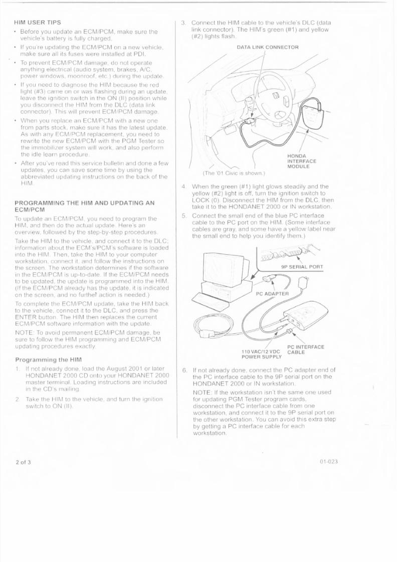
3, Connect the HIM cable to the vehicle's OLC (data
link connector). The HIM's green (#1) and yellow
(#2) lights flash.
DATA LINK CONNECTOR
/(The '01 Civic is shown.)
4 When the green (#1) light glows steadily and the
yellow (#2) light is off, turn the ignition switch to
LOCK (0). Disconnect the HIM from the OLC, thentake it to the HONOANET 2000 or IN workstation,
5. Connect the small end of the blue PC interface
cable to the PC port on the HIM. (Some interface
cables are gray, and some have a yellow label near
the small end to help you idenlify thern.)
6, If not already done, connect the PC adapter end of
the PC interface cable to the gp serial port on the
HONOANET 2000 or IN workstation,
NOTE: If the workstation isn't the same one used
for updating PGM Tester- program cards,
disconnect the PC interface cable from one
workstation, and connect it to the gp serial port on
the olher workstation You can avoid this extra step
by getting 8 PC interface cable for each
workstation.
01-02:3
8/2/2019 2002 Honda Odyssey TSB All
http://slidepdf.com/reader/full/2002-honda-odyssey-tsb-all 17/38
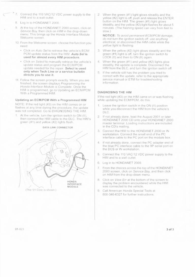
--, 7. Connect the 110 VAC/12 VDC power supply to the
HIM and to a wall outlet.
S. Log in to HONDANET 2000
9 AI the top of the HONDANET 2000 screen, click on
Service Bay. then click on HIM In the drop-down
menu. This brings up the Honda Interface ModuleWelcome screen
10. From the Welcome screen choose the function you
need:• Click on Allto 5el to retrieve the vehicle's ECMI
PCM update status from the HIM. Auto Sel is
used for almost every HIM procedure.
Click on Select to manually retrieve the vehicle's
update status and program the ECM/PCM
update needed for the repair. Select is used
only when Tech Line or a service bulletin
directs you to use it .
11 Follow the screen prompts exactly. When you are
finished, the screen displays Programming the
Honda Interface Module is Complete. Once the
HIM is proqrammad, go to Updating an ECM/PCM
With a Programmed HIM
Updating an ECM/PCM With a Programmed HIM
NOTE: If the red light (#3) on the HIM comes on or
flashes at any time during the procedure, the update
was not completed. Go to DIAGNOSING THE HIM
1 At the vehicle, turn the ignition switch to ON (II),
then connect the HIM cable to the OLe The HIM's
green (#1) and yellow (#2) lights flash
DATA LINK CONNECTOR
/
HONDA
INTERFACE
MODULE
(The 01 CiVIC is shown.)
01-023
2. When Ihe green (#1) liqhl glows steadily and the
yellow (#2) light is off. push and release Ihe ENTER
button on the HIM. The green (#1) light glows
steadily, and the yellow (#2) light flashes for about 5minutes. (The flashing speed can vary from fast toslow.)
NOTICE: To avoid permanent ECMIPCM damage,
do not turn the ignition switch, off, use anything
electrical, or disconnect the HIM cable while the
yellow light is flashing. .
3. When the yellow (#2) light glows steadily and the
green (#1) light is off, turn the ignition switch to
LOCK (0) and then to ON (II) again.
4 When the green (#1) and yellow (#2) lights glow
steadily, the update is complete. Disconnect the
HIM from the DLC, and turn the ignition switch off
5. If lhe vehicle still has the problern you tried to
correct with the update, reler to the appropriale
service manual or ETM for troubleshootinginformation
DIAGNOSING THE HIMIf the red light (#3) on the HIM came on or was flashing
while updating the ECM/PCM. do this:
1. Leave the ignition switch in the ON (II) position
whi Ie you disconnect the HIM from the vehicle's
DLC
2. If not already done, load the August 2001 or later
HONOANET 2000 CD onto your HONOANET 2000
master terminal. Loading instructions are includedin lhe CO's mailing.
3. Connect the HIM to the HONOANET 2000 or IN
workstation. Connect the small end of the PC
interface cable to the PC port on the module box.
4. If not already done, connect the PC adapter end of
the blue PC interface cable to the 9P serial port onthe OCS or IN workstation.
5. Connect the 110 VAC/12 VOC power supply to the
HIM and to a wall outlet.
6 Log in to HONDANET 2000
7 From the choices across the top of the HON DAN ET
2000 screen. click on Service Bay. and then clickon HIM from the drop-down menu.
8 Click on View Err at the bottom of the screen todisplay the problem encountered while the HIM
was connected to the vehicle.9. Call American Honda Special Tools at
800-346-6327 for further instructions.
3 of 3
8/2/2019 2002 Honda Odyssey TSB All
http://slidepdf.com/reader/full/2002-honda-odyssey-tsb-all 18/38
Level
o Service Bulletin 01-029aApplies To- ALL Models May 1,2001
Capturing and Downloading DTCs With the PGM Tester(Supersedes 01-029, dated March 20, 2001)
For warr-anty claim validation and payment on PGM-FI-
related repairs, youmust
l ist diagnostic trouble code(OTC) data in the appropriate field of the warrantyclaim form.
Beginning with PGM Tester software version SN122P
and revised HONDANET software (contained on the
February '01 HONDANET CD). you must also use the
PGM Tester to capture and store DTC data, then
download it to HONDANET 2000.
REQUIRED SPECIAL TOOLS AND EQUIPMENT
PGM Tester with SN122P or later software
HONDANET CD (February '01 or later)
PC Interface Cable (RS232) , TIN VET-O1002832AC Adapter Cable: TIN VET-020Q2426
HONDANET DCS Workstation
Order the PC Interface Cable (RS232) and the AC
Adapter Cable by contacting the Honda Tool and
Equipment Program at 1-888-424-6857. Phone lines
are open Monday through Friday from 7:30 a.m. to 700
p.m. CT.
WARRANTY CLAIM INFORMATION
I
or warranty claim information, reter to the appropriate
service bulletin or the flat rate manual.
Skill Level: Repair Technician
CAPTURING orcs (AT THE VEHICLE)
1. Connect the PGM Tester with SN122P or later
software to the 16P DLC.
2, Turn the ignition switch ON (II).
3. At the prompts, enter the VIN and odometer
reading.
4. From the SYSTEM SELECT screen, select 1:PGM-FI.
5. From the TEST MODE MENU PGM-FI screen,
select 1 : DTCs.
6, From the OTC MENU PGM-FI screen, select 1:
DTCs,
200' Arrlf'rlCiHl Hon-ta ~~1ot('iICo .Tnc. All 11"lghts 118Se'ved
7. From the CAPTURE D1C CODES screen, enter
the repair order number in the boxes, then pressENTER Make sure you fill in al/ the boxes on the
screen, or you will not be able to continue. If you
are entering a 5-digit repair order number, enter a
zero in the first box.
8, Monitor the screen display. The DTCs are
automatically sent to the PGM Tester When the
process is finished, you will see the message"Capture is Ccmplete.vb "
NOTE
• You are then asked if you want to download the
OTCs now or to continue. Pressing YES takes
you to the SEND DTC CODES screen; pressingNO takes you back to the TEST MODE MENU
PGM-FI screen.
• The PGM Tester can capture up to 25 DTCs, andit can store DTCs for a maximum of 15 days.
When the PGM Taster reaches either of these
limits, you must download all the DTCs, or the
PGM Tester is not usabte.
DOWNLOADING orcs (AT THE DCS
WORKSTATION)
Open HONOANET 2000.
2 At the top of the DCS display screen, click on
"Service Bay."3. From the pull-down menu, click on "PGM Tester,"
then "Retrieve OTC Codes."
4. At the bottom 01 the DCS display screen. click on
"Continue," (This takes you to the "Retrieve DTC
Codes" screen.)
5. Plug the blue PC Interface Cable (RS232) into thebottom of the PGM Tester,
6. Plug the AC Adapter Cable into the side of the PGMTester,
7. Turn on the PGM Tester.
8, From the PROGRAM MENU screen, select1 . HONDA SYSTEMS
g, From the VEHICLE CHECKS screen, press NO to
the query "Is this Electric Vehicle?" This brings up
the NO COMMUNICATION WITH PGM-FI screen,
To continue on, you need to start the stand-alone
mode; press YES.
ATB 2?493 ??f i?4 (01051 1 of 2
CUSTO MER INFO RMA TION: The informal ion in Ihi5 bulletin is intended for use only by skilled lechniCialls who have the prope r toots. equipmant.
and traininq 10correctty and safely mamlain your vehicle. These procedures should nol be attempted by "do-it-yourselfers," and you should not assume
this bulleun applies to your vehicle, or Ihal your vehicle has the condilion described. To determine whether this inrormation applies, contact an
authorized Honda automobile dealer.
8/2/2019 2002 Honda Odyssey TSB All
http://slidepdf.com/reader/full/2002-honda-odyssey-tsb-all 19/38
10. From the SYSTEM SELECT screen, select1: PGM-FI.
11. From the TEST MODE MENU-PGM-FI screen,
select 8: SEND DTC CODES, and press SEND.
12. At the bottom of the DCS display screen, click on
"Continue." The captured DTCs are automatically
downloaded to the HONDANET 2000. When the
download is complete, the PGM Tester clears all
OTCs stored in its memory, and you see thismessage on the screen
"OTC Codes Retrieval Process Complete"
"XX Transactions Received From PGM"
"XX Transactions Stored Successfully"
(XX = number of transactions downloaded)
13. Turn off the PGM Tesler.
14. Unplug the blue PC Interface Cable (RS232) and
the AC Adapter Cable.
2 of 2 01-029
8/2/2019 2002 Honda Odyssey TSB All
http://slidepdf.com/reader/full/2002-honda-odyssey-tsb-all 20/38
R
(gJ FlON"DA. Service Bulletin 01-051 [~:~]
May 8, 2001pplies To 1999-2001 Odyssey - ALL
Power Sliding Door Operation and Troubleshooting(Replaces 99·027, Power Sliding Door Problems, dated April 20, 1999)
BACKGROUND
The Odyssey EX power sliding door system has a
number of electrical and mechanical components that
must work in synchronization with each other for the
doors to open and close properly
This service bulletin describes tile main components ofthe power sliding door system, and it covers the
sequence of events that happens when a door opens
and closes. The Symptom Troubleshooting Chartcovers the most commonly reported problems with the
system.
COMPONENTS
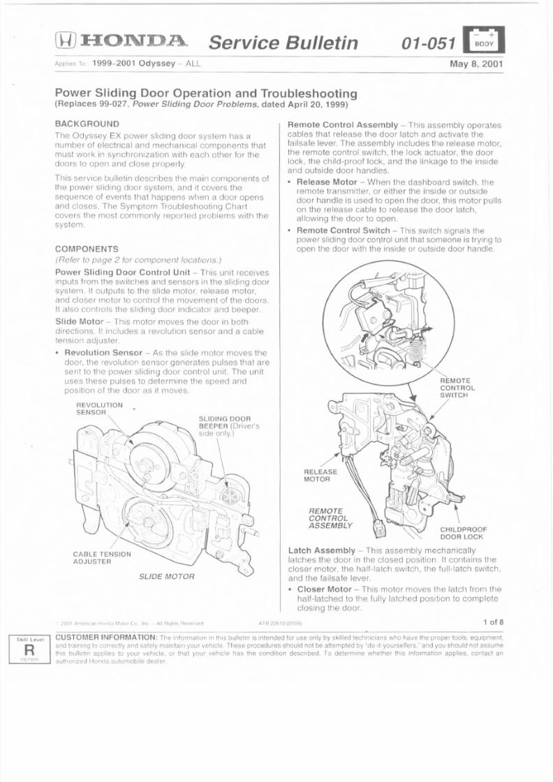
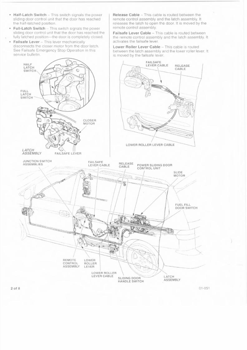
(Refer to page 2 for component tocetions.)Power Sliding Door Control Unit - This unit receives
inputs from the switches and sensors in the sliding door
system. It outputs to the slide motor, release motor,and closer motor to controllhe movement of the doors.
It also controls the sliding door indicator and beeper.
Slide Motor - This motor moves the door in both
directions It includes a revolution sensor and a cable
tension adjuster.
• Revolution Sensor - As the slide motor moves the
door, the revolution sensor generates pulses that are
sent to tile power sliding door control unit. The unit
uses these pulses to determine the speed and
position of the door as it moves.
SLIDING DOOR
CABLE TENSION
ADJUSTER
SLIDE MOTOR
ArA 226 \0 (0105!
Remote Control Assembly - This assembly operates
cables that release the door latch and activate thefailsafe lever. The assembly includes the release motor,the remote control switch, the lock actuator, the doorlock, the child-proof lock, and the linkage to the insideand outside door handles.
• Release Motor - When tile dashboard switch, tileremote transmitter, or either the inside or outside
door handle is used to open the door, this motor pullson the release cable to release the door latch,allowing the door to open.
• Remote Control Switch - This switch signals the
power sliding door control unit that someone is trying toopen the door with the inside or outside door handle.
REMOTE
CONTROL
SWITCH
/
RELEASE
MOTOR
REMOTECONTROL
ASSEMBLY CHILDPROOFDOOR LOCK
Latch Assembly - This assembly mechanically
latches the door in the closed position. It contains thecloser motor, the half-latch switch, the full-latch switch,
and the failsafe lever.
• Closer Motor - This motor moves the latch from the
half-latched to the fully latched position to complete
closing the door.
1 of 8
CUSTOMER INFORMATION: The inforrnat ion m t!l is bul letin is intended lor use only by skil led technicians who have the proper tools , equipment.
and training to correctly and safely mamtain your vehicle, These procedures should not be attempled by "do-it-yourselters," and you should not assume
this bul let in applies to your vehicle . or Ihat your vehicle has the condi tion described. To determine whether th is in format ion applies. contact an
authorized Honda automobile clealer
8/2/2019 2002 Honda Odyssey TSB All
http://slidepdf.com/reader/full/2002-honda-odyssey-tsb-all 21/38
Half-Latch Switch - This switch signals the power
sliding door control unit that the door has reached
Ihe half-latched position.
Full-Latch Switch - This switch signals the power
sliding door control unit that the door has reached the
fully latched position-the door is completely closed.
Failsafe Lever - This lever mechanically
disconnects the closer motor from the door latch.
See Failsafe Emergency Stop Operation in this
service bulletin.
LATCHASSEMBLY FAILSAFE LEVER
JUNCTION SWITCH
ASSEMBLIESFAILSAFE
LEVER CABLE
-:
REMOTE
CONTROL
ASSEMBLY
LOWER
ROLLER
LEVER
2 of 8
Release Cable - This cable is routed between the
remote control assembly and the latch assembly. It
releases the latch to open the door. It is moved by the
remote control assembly.
Failsafe Lever Cable - This cable is routed between
the remote control assembly and the latch assembly. It
activates the failsafe lever.
Lower Roller Lever Cable - This cable is routed
between the latch assembly and the lower roller lever. It
is moved by the failsafe lever.
RELEASE POWER SLIDING DOOR
CABLE CONTROL UNIT
FUEL FILL
DOOR SWITCH
.. .
\
LATCH
ASSEMBLY
01-051
8/2/2019 2002 Honda Odyssey TSB All
http://slidepdf.com/reader/full/2002-honda-odyssey-tsb-all 22/38
Lower Roller Lever - This lever is moved by the lower
roller lever cable. The lever contacts the sliding doorhandle switch.
Sliding Door Handle Switch - This switch works only
when the door is fully open. It is activated by the lower
roller lever. and signals the power sliding door controlunit that someone has moved either the inside or
outside door handle to close the door.
Junction Switch Assemblies - These are located in
the front of each door and in the B pillars. They are theonly electrical connection between the components in
the door and the power sliding door control unit whenthe door is closed. There is no electrical connection
when the door is open.
Keyless Receiver Unit - This unit is to the right of the
glove box It receives the door lock/unlock and sliding
door activation Signals from the remote transmitters.
When either the left sliding door or right sliding door
button is pushed on the remote transmitter. the receiverunit sends a Signal to the appropriate power Slidingdoor control unit.
NOTE: The doors will not operate with lhe remote
transmitter when the key is in the ignition switch.
SWITCHES AND INDICATORS
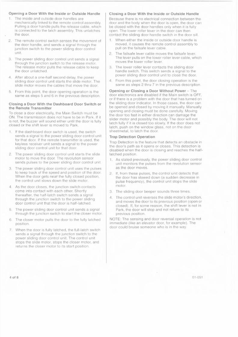
Main Switch - This switch, when it is OFF. turns off all
the electrical controls to the doors, and disables the
sliding door beeper_ The doors can only be opened andclosed manually,
Dashboard Door Switches - There is one rocker
switch for each door. Each switch signals its respective
power sliding door control unit that the driver wanls to
open or close that door.
MAIN SWITCH
> - - - : - " ? - - v . ,_ i ): U ' i,
(§~
'~iJiG~
f 8 JDASHBOARD DOOR
SWITCHES
01-051
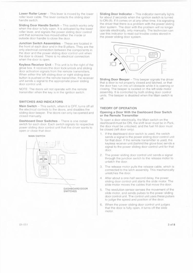
Sliding Door Indicator - This indicator normally lights
for about 2 seconds when the ignition switch is turned
to ON (II). If it comes on at any other time, it is signaling
the driver that there is a problem with the power sliding
door system. The door with the problem wilino longer
operate electrically, only manually. The technician can
use this indicator to read out trouble codes stored inthe power sliding door system.
Sliding Door Beeper - This beeper signals the driver
that a door is not properly closed and latched, or thatthe door has run into an obstacle while it is opening orclosing. The beeper is located on the left slide motor
assembly. It is controlled by both sliding door controlunits. The beeper is disabled when the Main switch isoff.
THEORY OF OPERATION
Opening a Door With the Dashboard Door Switch
or the Remote Transmitter
To open a door electrically, the Main switch on thedashboard must be ON, the shift lever must be in Park,
the door must be unlocked, and the fuel fill door must
be closed (left door only).
1. If the dashboard door switch is used, the switch
sends a signal to the power sliding door control unit
for that door. If the remote transmitter is used, the
keyless receiver unit (behind the glove box) sends a
signal to the power sliding door control unit for thai
door.
2. The power sliding door control unit sends a signal
through the junction switch to the release motor to
unlatch the door.
3. The release motor pulls the release cable, which is
connected to the latch assembly. This mechanically
unlatches the door.
4 After about a one-half second delay. the power
sliding door control unit starts the slide motor. Tile
slide motor moves the cables that move the door.
5. The revolution sensor senses the movement of the
slide motor. and sends pulses to the power sliding
door control unit. The control unit uses these pulses
to judge the speed and position of the door,
6. When the power sliding door control unit judges
that the door is fully open. it turns off the slide
motor.
3 of 8
8/2/2019 2002 Honda Odyssey TSB All
http://slidepdf.com/reader/full/2002-honda-odyssey-tsb-all 23/38
pening a Door With the Inside or Outside Handle
. The inside and outside door handles aremechanically linked to the remote control assembly.Pulling a door handle pulls the release cable, which
is connected to the latch assembly. This unlatchesthe door.
. The remote control switch senses the movement of
the door handle, and sends a signal through the
junction switch to the power sliding door control
unit
. The power sliding door control unit sends a signal
through the junction switch to the release motor.The release motor pulls the release cable to keepthe door unlatched.
. After about a one-half second delay, the power
sliding door control unit starts the slide motor. The
slide motor moves the cables that move the door.
, From this point, the door opening operation is the
same as steps 5 and 6 in the previous description.
losing a Door With the Dashboard Door Switch or
e Remote Transmitter
o close a door electrically, lha Main Switch must beN. The transmission does not have to be in Park, If it
not, the buzzer will sound either until the door is fullylosed or the shift lever is moved to Park,
, If the dashboard door swilch is used, the switch
sends a signal to the power sliding door control unit
for that door. If the remote transmitter is used, the
keyless receiver unit sends a signal to the power
sliding door control unit for that door.
, The power sliding door control unit starts the slide
motor to move the door. The revolution sensor
sends pulses to the power sliding door control unit
. The power sliding door control unit uses the pulses
to keep track of the speed and position of the door
When the door gets near the fully closed position,
the control unit slows down the slide motor.
. As the door closes, the junction switch contacts
come into contact with each other. Shortly
thereafter, the half-latch switch sends a signal
through the junction switch to the power sliding
door control unit that the door is half-latched.
. The power sliding door control unit sends a signalthrough the junction switch to start the closer motor,
. The closer motor pulls the door to the fully latched
position.
. When the door is fully latched, the full-latch switch
sends a signal through the Junction switch to the
power sliding door control unit. The control unit
stops the slide motor, stops the closer motor, and
returns the closer motor to its start position.
of B
Closing a Door With the Inside or Outside Handle
Because there is no electrical connection between thedoor and the body when the door is open, the door can
be closed with the door handles only when it is fully
open The lower roller lever in the door can then
contact the sliding door handle switch in the door sill.
1. When either the inside or outside door handle is
moved, it causes the remote control assembly topull on the failsafe lever cable.
2. The failsafe lever cable moves the failsafe lever.
The lever pulls on the lower roller lever cable, whichmoves the lower roller lever,
3. The lower roller lever contacts the sliding door
handle switch. This switch sends a signal to the
power sliding door control unit to close the door.
4. From this point, the door closing operation is the
same as steps 2 thru 7 in the previous description.
Opening or Closing a Door Without Power - The
door electronics are disabled if the Main switch is OFF,
or if there is a problem with the door that has turned on
the sliding door indicator. In those cases, the door can
be opened and closed by moving it manually. Manually
opening and closing must be done carefully. Moving
the door too fast in either direction can damage the
slider motor and possibly the body. The door will not
latch fully if it is closed too slowly. If the door does not
latch, push on the window glass, not on the doorsheetmetal, to latch the door.
Trap Detection Operation
Trap Detection is the feature that detects an obstacle in
the door's path as it opens or closes. This detection is
disabled when the door is closing and reaches the half-
latched position.
1. As stated previously, the power sliding door control
unit monitors the pulses from the revolution sensor
as the door moves,
2. If, from these pulses, the control unit detects that
the door has slowed down (a sudden decrease in
pulse frequency), the control unit stops the slide
motor.
3 The sliding door beeper sounds three times.
4. The control unit reverses the slide motor's direction,
and moves the door to its previous position (open or
closed). If, for some reason, the shift lever is not in
Park, the door will stop and not return to its
previous position,
NOTE: The sensing and door reversal operation is not
immediate (like an elevator door, for example). The
door could bruise someone who is in the way.
01-051
8/2/2019 2002 Honda Odyssey TSB All
http://slidepdf.com/reader/full/2002-honda-odyssey-tsb-all 24/38
Emergency Stop Operation
The Emergency Stop feature allows the operator to
stop the door lor any reason when it is opening or
closing. It can be activated at any time with the door
switch on the dashboard, or with the remote
transmitter. It can also be activated by either door
handle only if the door is closed far enough that the
junction switches are making contact. Turning the Mainswitch OFF also stops door movement.
1. If, while the door is moving, the power sliding doorcontrol unit receives an open or close signal from
the door switch or the remote transmitter, or a
signal through the Junction switch from the remote
control switch, it immediately stops the slide motor.
2. The sliding door beeper sounds three times (i f the
Main switch was not used to stop door movement).
3. If the remote transmitter is used to move the doorafter it has stopped, the door will move in the
opposite direction. If the dashboard door switch is
used, the door will move in the direction selected onthe switch,
Failsafe Emergency Stop OperationThe Failsafe Emergency Stop feature works only when
the closer motor is moving the door from half-latched to
fully latched. It can be activated by the dashboard door
switch, the remote transmitter, or either of the door
handles.
1. The power sliding door control unit receives an
open or close signal from the door switch or ~heremote transmitter (through the keyless receiverunit)
or
the remote control switch sends a signal through
the Junction switch that a door handle has been
pulled.
2. If a door handle 'was used, the linkage pulls the
failsafe lever cable. If the door switch or remote
transmitter was used, the power sliding door control
unit sends a signal through the junction switch tothe remote control unit to pull the failsafe lever
cable,
3. The failsafe lever cable raises the failsafe lever,
which disengages the closer motor from the lalch.
4, The beeper sounds three times.
5. The power sliding door control unit stops and
reverses the slide molar. If the door opening signal
came from the dashboard door switch or theremote transmitter, the door is opened about 9
inches. If the door opening signal came from a door
handle, the door is opened all the way_
01-051
Fuel Fill Door Operation
The left door locks automatically when the fuel f ill door
is opened,
When the fuel fill door is opened (using the release
lever next to the driver's seat), the fuel fill door
switch closes, This energizes the fuel fill door relay,
2. The relay sends a signal through the junction switchto the sliding door lock control unit. This assembly
locks the door.
The door does not unlock automatically when the fuelfill door is closed. It must be unlocked with the lock
knob on the inside of the door, the power door locks, or
the remote transmitter.
If you attempt to unlock the left door while the fuel fill
door is open, it will lock again. You can override this
automatic lock by pushing the lock knob to the unlock
posit ion and holding it there for several seconds. Thedoor can now operate in its normal automatic modes.
You can cause serious damage to the door or the fuel
f ill door by opening the 'sliding door.
SLIDING DOOR BEEPER LOGIC
The Sliding door beeper informs the driver that therehas been a problem with a door's normal operation. It
can also, in some cases, be a help in diagnosing a
problem.
Solid Tone - A solid, continuous tone means that the
door is open, not moving, and the shift lever is not in
Park. This is caused by the power sliding door control
unit not receiving a signal from the full-latch switch
through the junction switch, no Park signal, and the unit
is not moving the door.
Since both power sliding door control units use the
same beeper, it may be hard to determine which door
is al fault With the beeper sounding, push each
dashboard door switch to Ihe CLOSE position. The
beeper will stop when you press the switch for the door
with the problem.
Continuous Beep - The beeper beeps continuously
when the shift lever is moved out of Park and the door
is closing. It should stop when the door is fully latched.
Three Beeps, Door Stops - See Emergency Stop
Operation.
Three Beeps, Door Reverses Direction - See Trap
Detection Operation and Failsafe Emergency Stop
Operation,
Five Beeps - Diagnosis should show that the door is
half latched but not fully latched The power sliding
door control unit did not receive a signal from the half-
latch switch, so it did not power the closer motor. See
the Symptom Troubleshooting Chart at the end of Ihis
service bulletin.
5 of 8
8/2/2019 2002 Honda Odyssey TSB All
http://slidepdf.com/reader/full/2002-honda-odyssey-tsb-all 25/38
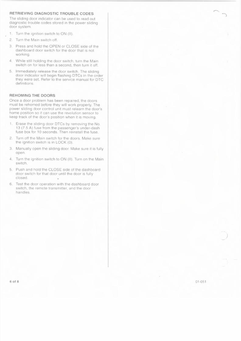
TRIEVING DIAGNOSTIC TROUBLE CODES
he sliding door indicator can be used to read out
iagnostic trouble codes stored in the power slidingor system,
Turn the ignition switch to ON (II).
Turn the Main switch off.
. Press and hold the OPEN or CLOSE side of the
dashboard door switch for the door that is not
working.
. While still holding the door switch, turn the Main
switch on for less than a second, then turn it off.
. Immediately release the door switch. The sliding
door indicator will begin flashing OTCs in the orderthey were set Refer to the service manual for OTCdefinitions.
EHOMING THE DOORS
nce a door problem has been repaired, the doors
ust be rehomed before they will work properly. The
ower sliding door control unit must relearn the door'some position so it can use the revolution sensor to
eep track of the door's position when it is moving.
. Erase the sliding door OTCs by removing the No.
13 (7.5 A) fuse from the passenger's under-dash
fuse box for 10 seconds. Then reinstall the fuse.
. Turn off the Main switch for the doors. Make sure
the ignition switch is in LOCK (0).
. Manually open the sliding door. Make sure it is fullyopen,
. Turn the ignition switch to ON (II). Turn on the Main
switch.
. Push and hold the CLOSE side of the dashboard
door switch for that door until the door is fully
closed.
. Test the door operation with the dashboard door
switch, tile remote transmitter, and the door
handles
of 8 01-051
8/2/2019 2002 Honda Odyssey TSB All
http://slidepdf.com/reader/full/2002-honda-odyssey-tsb-all 26/38
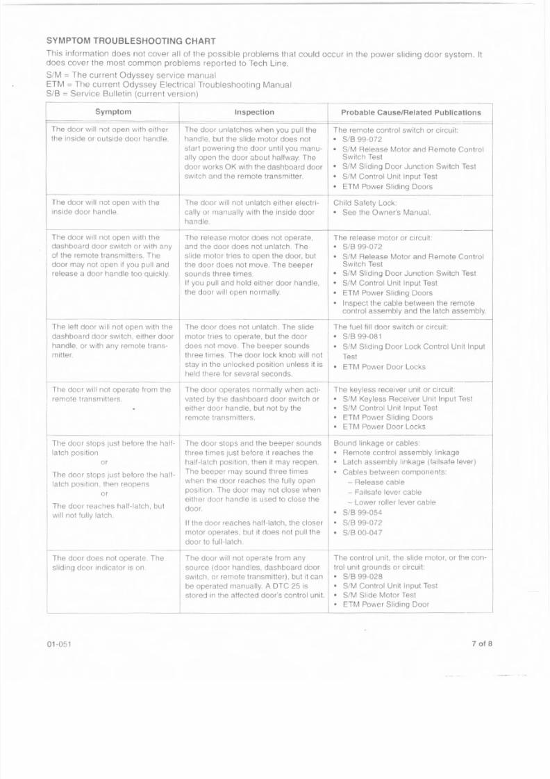
SYMPTOM TROUBLESHOOTING CHART
This information does not cover all of the possible problems that could occur in the power sliding door system. Itdoes cover the most common problems reported to Tech Line.
SIM = The current Odyssey service manual
ETM = The current Odyssey Electrical Troubleshooting Manual
SIB = Service Bulletin (current version)
Symptom
The door will not open with eitherthe inside or outside door handle.
The door will not open with the
inside door handle.
1--- ---- ------
The door will not open with the
dashboard door switch or with any
of the remote transmitters. The
door may not open if you pull and
release a door handle too quickly.
Inspection Probable Cause/Related Publications
The door unlatches when you pull thehandle, but the slide motor does not
start powering the door until you manu-
ally open the door 'about halfway. The
door works OK with the dashboard door
switch and the remote transmitter.
The remote control switch or circuit:• SIB 99-072
• 81M Release Motor and Remote ControlSwitch Test
• 81M Sliding Door Junction Switch Test
• 81M Control Unit Input Test
• ETM Power Sliding Doors
Child Safety Lock:
• See the Owner's Manual.
The door will not unlatch either electri-
cally or manually with the inside door
handle
The release motor does not operate,
and the door does not unlatch. The
slide motor tries to open the door, but
the door does not move. The beeper
sounds three times,
If you pull and hold either door handle,
the door wil l open normally.
The left door will not open with the
dashboard door switch, either door
handle, or with any remote trans-
mitter.
The door will not operate from tile
remote transmitters.
The door stops just before the hatf-
latch position
or
The door stops just before the half-
latch position, then reopens
or
The door reaches half- latch, but
wil l not ful ly latch.
The door does not operate. The
slidinq door Indicator is on.
The door does not unlatch, The slide
motor tr ies to operate, but the door
does not move. The beeper sounds
three times. The door lock knob will not
The release motor or circuit:
• SIB 99-072
• SIM Release Motor and Remote Control
Switch Test• 81M Sliding Door Junction Switch Test
• SIM Control Unit Input Test
• ETM Power Sliding Doors
• Inspect the cable between the remotecontrol assembly and the latch assembly.
The fuel fill door switch or circuit:
• 8/B 99-081
• 81M Sliding Door Lock Control Unit Input
Test
stay in the unlocked position unless it is • ETM Power Door Locks
held there for several seconds.
The door operates normally when acti-
vated by the dashboard door switch or
either door handle, but not by the
remote transmitters.
The door stops and the beeper sounds
three times just before it reaches the
half-latch position, then it may reopen.
The beeper may sound three times
when the door reaches the fully open
posit ion. The door may not close when
either door handle is used to close the
door.
TIle keyless receiver unit or circuit:
• SIM Keyless Receiver Unit Input Test
• 81M Control Unit Input Test
• ETM Power Sliding Doors
• ETM Power Door Locks
Bound linkage or cables:
• Remote control assembly linkage
• Latch assembly linkage (failsafe lever)
• Cables between components:
- Release cable
- Failsafe lever cable
- Lower roller lever cable
• SIB 99-054
IIthe door reaches half-latch, the closer • SIB
99-072motor operates, but it cJoesnot pull the • SIB 00-047
door to full-latch.
The door will not operate from any
source (door handles, dashboard door
switch, or remote transmitter). but it can
be operated manually. A OTC 25 is
stored in the affected door's control unit.
The control unit, the slide motor, or the con-
trol unit grounds or circuit:
• SIB 99-028
• SIM Control Unit Input Test
• 81M Slide Motor Test
• ETM Power Sliding Door
01-051 7 of 8
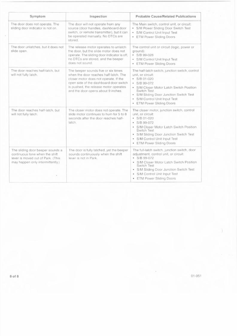
8/2/2019 2002 Honda Odyssey TSB All
http://slidepdf.com/reader/full/2002-honda-odyssey-tsb-all 27/38
Symptom Inspection Probable Cause/Related Publications
The door does not operate. The The door will not operate from any The Main switch, control unit, or circuil:
sliding door indicator is not on. source (door handles, dashboard door · SIM Power Sliding Door Switch Test
switch, or remote transmitter), but it can · SIM Control Unit Input Test
be operated manually. No DTCs are • ETM Power Sliding Doorsstored.
-The door unlatches, but it does not The release motor operates to unlatch The control unit or circuit (logic, power or
slide open. the door, but the slide motor does not ground)
operate. The sliding door indicator is off, · SIS 99-028no DTCs are stored, and the beeper ·SIM Control Unit Input Test
does not sound. · ETM Power Sliding Doors
The door reaches halt- latch, but The beeper sounds five or six times The hall-latch switch, junction switch, control
wil l not fully latch. when the door reaches half- latch. The unit, or circuit:
closer motor does not operate. If the • SIB 01-020
open side of the dashboard door switch · SIB99-072is pushed, the release motor operates · SIM Closer Motor Latch Switch Positionand the door opens about 9 inches. Switch Test
· SIM Sliding Door Junction Switch Test
• SIM Control Unit Input Test
· ETM Power Sliding Doors
The door reaches half-latch, but The closer motor does not operate. The The closer motor, junction switch, control
wil l not ful ly latch. slide motor continues to hum for 5 to 8 unit. or circuit:
seconds after the door reaches half- • SIB 01-020
latch. · SIB 99-072• SIM Closer Motor Latch Switch PositionSwitch Test
·SIM Sliding Door Junct ion Switch Test
· SIM Control Unit Input Test
• ETM Power Sliding Doors
-The sliding door beeper sounds a The door is fully latched, yet the beeper The ful l-latch switch, Junction switch, door
continuous tone when the shift sounds continuously when the shift adjustment, control unit, or circuit:
lever is moved out of Park. (This lever is not in Park. · SIB 99-072
may happen only intermittently.) · SIM Closer Motor Latch Switch PositionSwitch Test
·SIM Sliding Door Junction Switch Test
· SIM Control Unit Input Test
· ETM Power Sliding Doors
of 8 01-051
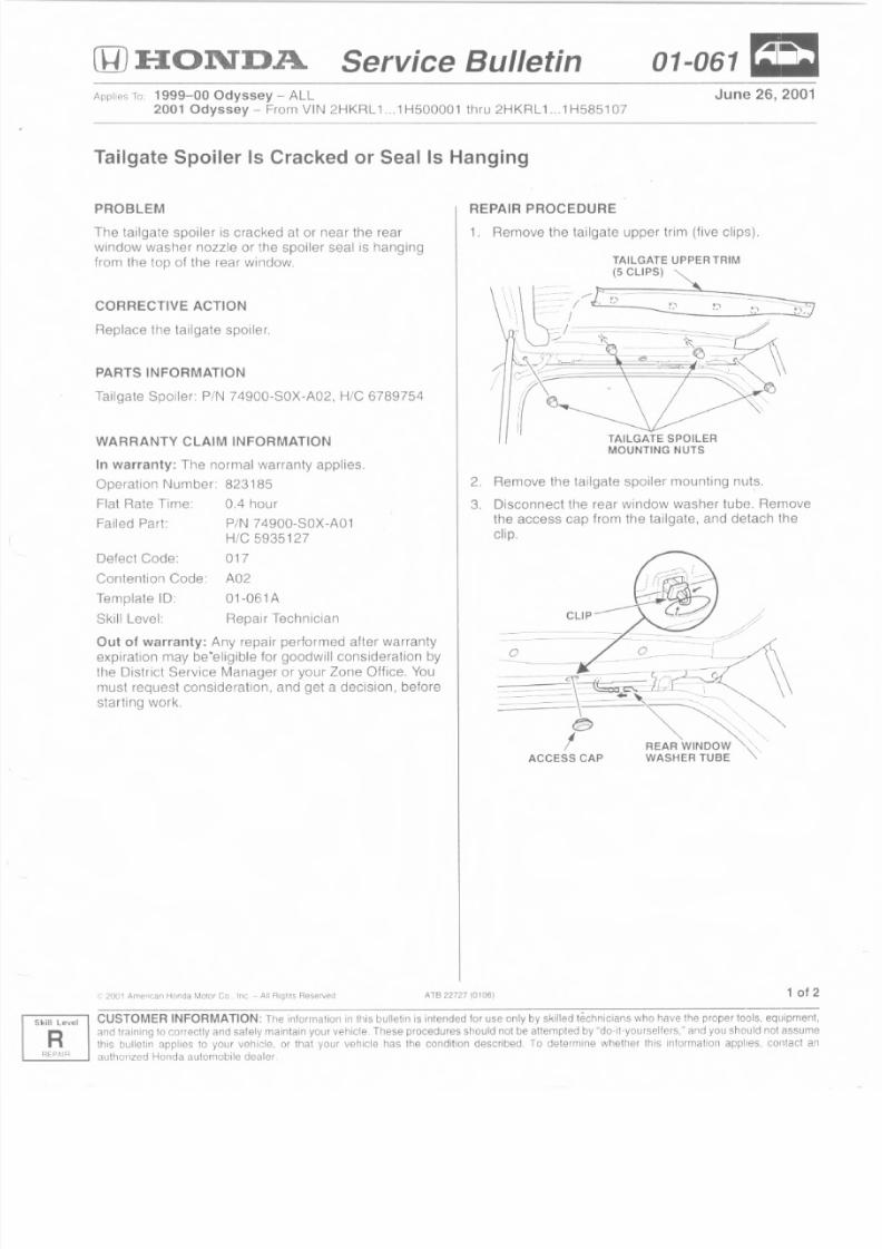
8/2/2019 2002 Honda Odyssey TSB All
http://slidepdf.com/reader/full/2002-honda-odyssey-tsb-all 28/38
Level
RREPAI"
(IlJ :HON"D.A Service Bulletin 01-061=June 26, 2001pplies To 1999~OO Odyssey - ALL
2001 Odyssey - From VIN 2HKRL 1 __1H500001 thru 2HKRL 1.._1H5851 07
Tailgate Spoiler Is Cracked or Seal Is Hanging
PROBLEM
The tailgate spoiler is cracked at or near the rear
window washer nozzle or the spoiler seal is hanging
from the top of the rear window,
CORRECTIVE ACTION
Replace the tailgate spoiler
PARTS INFORMATION
Tailgate Spoiler: PIN 74900-S0X-A02, Hie 6789754
WARRANTY CLAIM INFORMATION
In warranty: The normal warranty applies,
Operation Number, 823185
Flat Rate Time: 0.4 hour
Failed Part: PIN 74900-S0X·A01
HIC 5935127
017
A02
01-061A
Repair Technician
Defect Code:
Conlention Code:
Templale 10:
Skill Level:
Out of warranty: Any repair performed after warranty
expiration may be"eligible for goodwill consideration by
the District Service Manager or your Zone Office. You
must request consideration, and get a decision, before
starting work.
~- 2001 Ame"cao Honda MoW Co., Inc. - All Righi, Reserved ATB 22727 10 I06)
REPAIR PROCEDURE
1. Remove the tailgate upper trim (five clips).
/
TAILGATE UPPER TRIM
'\ __ .(5CL~~
\"'~-.---rs -\ " ' , = ~ - - - : - . f) ------2~} ~I !_~ _
TAILGATE SPOILERMOUNTING NUTS
2. Remove the tailgate spoiler mounting nuts.
3 _ Disconnect the rear window washer tube. Removethe access cap from the tailgate, and detach the
clip,
o 0. _
- ~-.'-;- -~.------ - C~ ~ ._ :_ - - i b " ~ __ _ _ l_ t , . c ' - _ _~ '
= -c_-~ ::~ ~~:;~"
I REAR WINDOW"\, -,
ACCESS CAP WASHER TUBE
1 of 2
GUSTO MER INFORMATION: The informat ion in this bulletin is intended for use only by ski lled technicians who have the proper tools. equipment,
and Iraining 10 correclly and safely maintain your vehicle, These procedures should nol be attempted by "do-it-yourselters." and you should nol assume
this bulleti 11 appl ies to your vehicle. or Ihat you r veh icle has the condition described. To dele rmine w helher this intorrnat ion applies, contact an
authorized Honda automobile dealer,
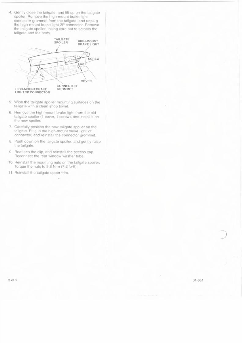
8/2/2019 2002 Honda Odyssey TSB All
http://slidepdf.com/reader/full/2002-honda-odyssey-tsb-all 29/38
. Gently close the tailgate, and lift up on the tailgate
spoiler. Remove the high-mount brake light
connector grommet from the tailgate, and unplug
the high-mount brake light 2P connector. Remove
the tailgate spoiler, taking care not to scratch the
tailgate and the body.
. Wipe the tailgate spoiler mounting surfaces Oil thetailgate with a clean shop towel.
. Remove the high-mount brake light from the old
tailgate spoiler (1 cover, 1 screw), and install it onthe new spoiler.
. Carefully position the new tailgate spoiler on the
tailgate. Plug in the high-mount brake light 2P
connector, and reinstall the connector grommet.
. Push down on the tailgate spoiler, and gently raise
the tailgate.
. Reattach the clip, and reinstall the access cap
Reconnect the rear window washer tube.
0. Reinstall the mounting nuts on the tailgate spoiler.
Torque the nuts to 9.8 N·m (7.2 Ib-ft).
1. Reinstall the tailgate upper trim.
)
01-061
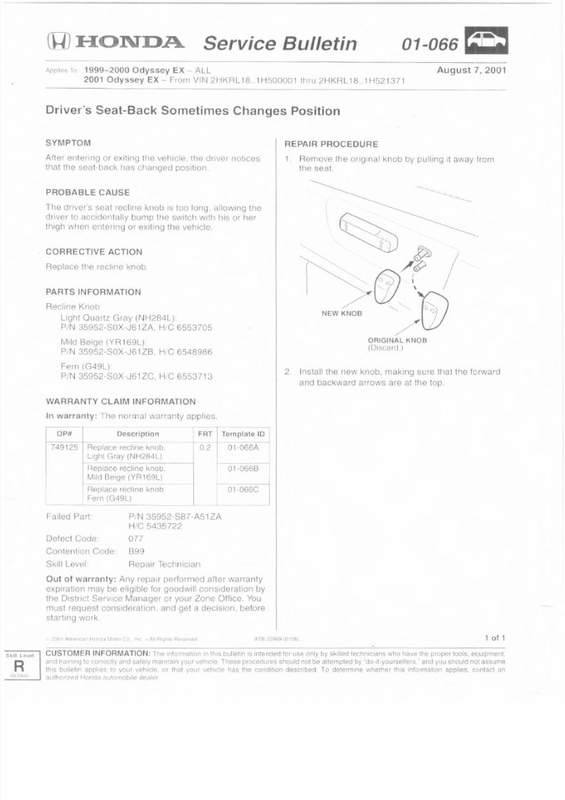
8/2/2019 2002 Honda Odyssey TSB All
http://slidepdf.com/reader/full/2002-honda-odyssey-tsb-all 30/38
Service Bulletin 01-066=
August 7, 2001pplies To 1999-2000 Odyssey EX - ALL
2001 Odyssey EX - From VIN 2HKRL 18..1HS00001 thru 2HKRL 18 .1H521371
Driver's Seat-Back Sometimes Changes Position
SYMPTOM
After entering or exiting the vehicle, the driver noticesthat the seat-back has changed position.
PROBABLE CAUSE
The driver's seat recline knob is too long. allowing the
driver to accidentally bump the switch with his or her
thigh when entering or exiting the vehicle.
CORRECTIVE ACTION
Replace the recline knob.
PARTS INFORMATION
Recline Knob
Light Quartz Gray (NH284L):
P IN 35952-S0X-J61 z»: Hie 6553705
Mild Beige (YR169L).
P IN 35952-S0X-J61 lB, Hie 6548986
Fern (G49L).
PIN 35952-S0X-J61 zc. Hie 6553713
WARRANTY CLAIM INFORMATIONIn warranty: The normal warranty applies
n FRT Tempi~
ob, 0.2 01-066A I
L )
ob, 01-0668
L )--- ~ob, 01-066C
OPH Descriptio
749125 Replace recline kn
Light Gray (NH284
Replace recline kn
Mild Beige (YR169
ReplAce recline kn
Fern (G49L)
Failed Part PIN 35952-S87 -AS1ZA
Hie 5435722
Defect Code: 077Contention Code B99
Skill Level. Repair Technician
Out of warranty: Any repair performed after warranty
expiration may be eligible for goodwill consideration by
the District Service Manager or your Zone Office. You
must request consideration. and get a decision, before
starting work.
2001 Amer cai Herron \101or Co .nc - ,.'\1Ri ' : J111~Hnservcrt
REPAIR PROCEDURE
1, Remove the original knob by pulling it away fromthe seal.
~
~'-~~.
t'~~;p /
I ~{j)\ ·/ <>~
NEWKN08 /(21ORIGINAL KNOB
(Dtscard.)
2. Install the new knob. making sure that the forward
and backward arrows are at the top,
1 of 1
el CUSTOMER INFORMATION: The inforrnalion in this bulletin is intended for use only by Skilled technicians who have tile proper tools, equipment,
and training to correctly and sately maintain your vehicle, These procedures should not be attempted by "oo-u-yourseuers. ' and you should not assume
this oullsnn applies to your vehlclQ, or that your vehicle has the condition described. To determine whether this information applies. contact < in
aurhonzed Honda autornobile dealer,
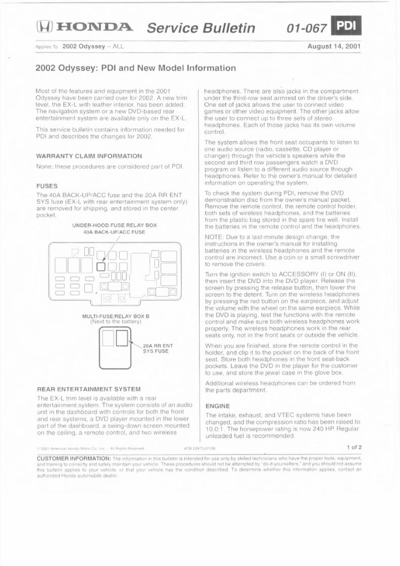
8/2/2019 2002 Honda Odyssey TSB All
http://slidepdf.com/reader/full/2002-honda-odyssey-tsb-all 31/38
[DFIO:ND.A. Service Bulletin 01-067&
Applies To; 2002 Odyssey - ALL August 14, 2001
2002 Odyssey: POI and New Model Information
Most of the features and equipment in the 2001
Odyssey have been carried over for 2002. A new trim
level, the EX-L with leather interior, has been added.
The navigation system or a new OVO-based rear
entertainment system are available only on the EX-L.
This service bulletin contains information needed for
POI and describes Hie changes for 2002.
WARRANTY CLAIM INFORMATION
None; these procedures are considered part of POI.
FUSES
The 40A BACK-UP/ACC fuse and the 20A RR ENTSYS fuse (EX-L with rear entertainment system only)
are removed for shipping, and stored in the center
pocket.
UNDER-HOOD FUSE RELAY BOX
40A BACK-UP/ACC FUSE
I ?Do06o~oolIDDOoOOI 1
00o0 CJ O O o o r \ 001000 ~ .,-~~ ,.·UgJ.l9~~ '
MULTI-FUSE/RELAY BOX B
(Next to the battery)
D D ~ 2 0 A RR ENT
SY S FUSE
REAR ENTERTAINMENT SYSTEM
The EX-L trim level is available with a rear
entertainment system. The system consists of an audio
unit in the dashboard with controls for both the front
and rear systems, a OVD player mounted in the lower
part of the dashboard, a swing-down screen mounted
on the ceiling, a remote control, and two wireless
A IB 22973 (0106)
headphones. There are also jacks in the compartment
under the third-row seat armrest on the driver's side.
One set of jacks allows the user to connect video
games or other video equipment. The other jacks allow
the user to connect up to three sets of stereo
headphones. Each of those jacks has its own volume
control.
The system allows the front seat occupants to listen to
one audio source (radio, cassette, CD player or
chanqer) through the vehicle's speakers while the
second and third row passengers watch a OVO
program or listen to a different audio source through
headphones Refer to the owner's manual lor detailed
information on operating the system.
To check the system during POI, remove the OVOdemonstration disc from the owner's manual packet.Remove the remote control, the remote control holder,
both sets of wireless headphones, and the batteries
from the plastic bag stored in the spare tire well Install
the batteries in tile remote control and the headphones.
NOTE: Due to a last-minute design change, the
instructions in the owner's manual for installing
batteries in the wireless headphones and the remote
control are incorrect. Use a coin or a small screwdriver
to remove the covers.
Turn the ignition switch to ACCESSORY (I) or ON (II),
then insert the DVD into the OVD player. Release the
screen by pressing the release button. then lower thescreen to the detent. Turn on the wireless headphones
by pressing the red button on the earpiece, and adjust
tile volume with the wheelan the same earpiece. While
the OVD is playing, test the functions with the remote
control and make sure both wireless headphones work
properly. The wireless headphones work in the rear
seats only, not in the front seats or outside the vehicle.
When you are finished, store tile remote control in the
holder, and clip it to the pocket on the back of the front
seat, Store both headphones in the front seat-back
pockets, Leave tile OVD in the player for the customer
to use, and store the jewel case in the glove box.
Additional wireless headphones call be ordered fromthe parts department.
ENGINE
The intake, exhaust, and VTEC systems have been
changed, and the compression ratio has been raised to
10.0: 1. The horsepower rating is now 240 HP Regular
unleaded fuel is recommended.
1 of 2
CUSTOMER INFORMATION: The information in this bul letin is intended for LIse only by skilled technicians who have the proper tools, equipment,
and training to correctly and safely maintain your vehicle. These procedures should not be attempted by "do-lt-yourselters." and you should not assume
thrs bul letin applies to your vehicle. 01 that your vehicle has tile condition described. To determine whether th is information applies, contact an
authorized Honda automobile dealer.
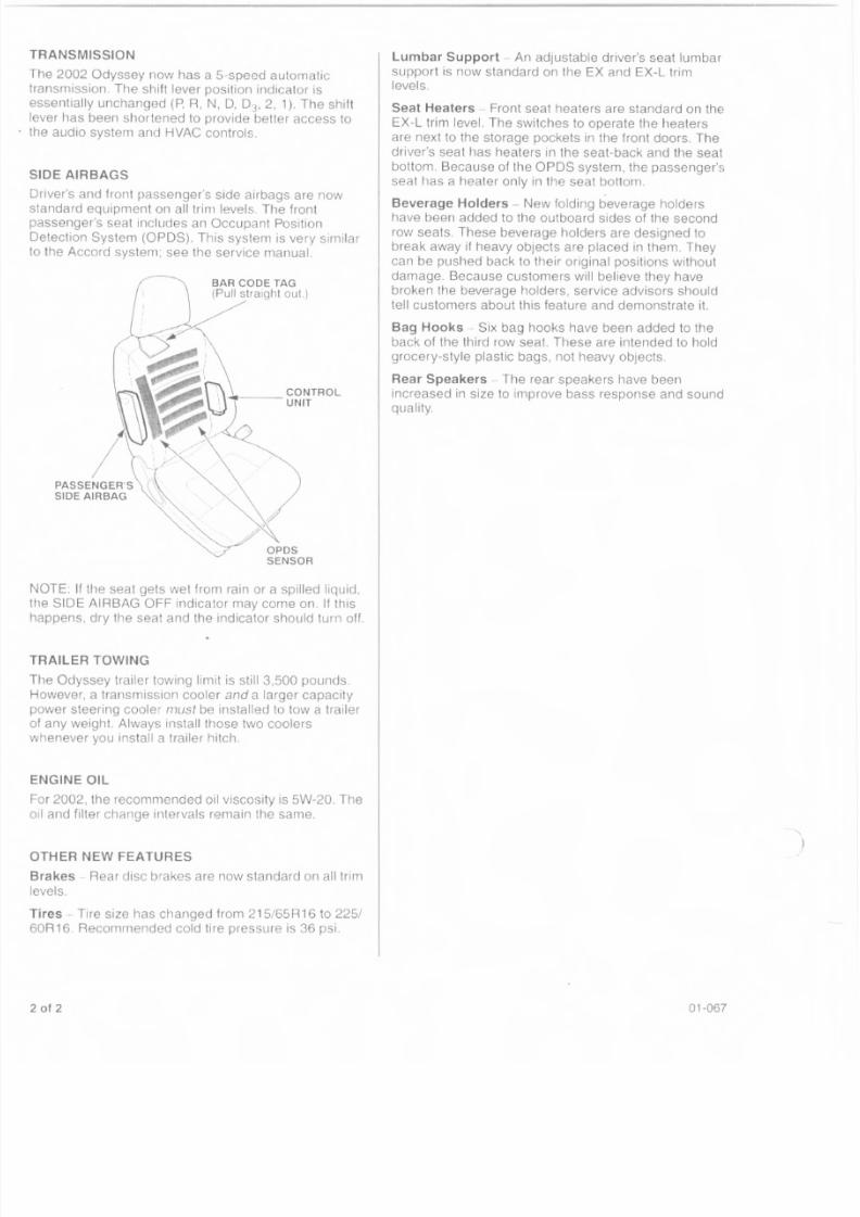
8/2/2019 2002 Honda Odyssey TSB All
http://slidepdf.com/reader/full/2002-honda-odyssey-tsb-all 32/38
he 2002 Odyssey now has a 5-speed automatic
ansmission. The shift lever posit ion indicator is
ssentially unchanged (P. R, N, 0, 03,2, 1). The shift
ver has been shortened to provide better access to
e audio system and HVAC controls.
DE AIRBAGS
river's and front passenger's side airbags are now
tandard equipment on all trim levels. The frontassenger's seat includes an Occupant Position
etection System (OPDS). This system is very similar
the Accord system; see the service manual.
OTE: If the seat gets wet from rain or a spilled liquid.
e SIDE AIRBAG OFF indicator may come on. If this
appens, dry the seat and the indicator should turn off.
AILER TOWING
he Odyssey trailer towing limit is still 3,500 pounds.
wever, a transmission cooler and a larger capacity
wer steering cooler must be installed to tow a trailer
f any weight. Always install those two coolers
henever you install a trailer hitch.
NGINE OIL
r 2002, the recommended oil viscosity is 5W-20. The
il and filter change intervals remain the same.
HER NEW FEATURES
Rear disc brakes are now standard on all trim
ires - Tire size has changed from 215i65R16 to 2251
Recommended cold ti re pressure is 36 psi.
of 2
Lumbar Support - An adjustable driver's seat lumbar
support is now standard on the EX and EX-L trim
levels.
Seat Heaters - Front seat heaters are standard on the
EX-L trim level. The switches to operate the heaters
are next to the storage pockets in the front doors. The
driver's seat has heaters in the seat-back and the seat
bottom. Because of the OPDS system, the passenger's
seat has a heater only in the seat bottom.
Beverage Holders - New folding beverage holdershave been added to the outboard sides of the second
row seats. These beverage holders are designed to
break away i f heavy objects are placed in them. They
can be pushed back to their original positions without
damage. Because customers will believe they have
broken the beverage holders, service advisors should
tell customers about this feature and demonstrate it.
Bag Hooks - Six bag hooks have been added to the
back of the third row seat. These are intended to hold
grocery-style plastic bags, not heavy objects
Rear Speakers - The rear speakers have been
increased in size to improve bass response and sound
quality.
01-067
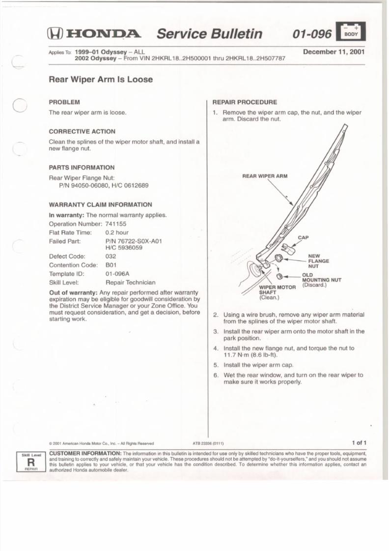
8/2/2019 2002 Honda Odyssey TSB All
http://slidepdf.com/reader/full/2002-honda-odyssey-tsb-all 33/38
Service Bulletin 01-o96[~1December 11, 2001Applies To: 1999-01 Odyssey - ALL
2002 Odyssey - From VIN 2HKRL 18..2H500001 thru 2HKRL 18..2H507787
Rear Wiper Arm Is Loose
PROBLEM
The rear wiper armis loose.
CORRECTIVE ACTION
Clean the splines of the wiper motor shaft, and install a
new flange nut.
PARTS INFORMATION
Rear Wiper Flange Nut:
PIN 94050-06080, Hie 0612689
WARRANTY CLAIM INFORMATION
In warranty: The normal warranty applies.
Operation Number: 741155
Flat Rate Time: 0.2 hour
Failed Part: PIN 76722-S0X-A01Hie 5936059
Defect Code: 032
Contention Code: BO I
Template 10: 01-096A
Skill Level: Repair Technician
Out of warranty: Any repair performed after warranty
expiration may be eligible for goodwill consideration by
the District Service Manager or your Zone Office. You
must request consideration, and get a decision, before
starting work.
~ 2 00 1 A me ric an H on da M oto r C o . • I nc . - A ll R lg hls R e se rv ed ATB 23336 (0111)
REPAIR PROCEDURE
1. Remove the wiper arm cap, the nut, and the wiper
arm. Discard the nul.
REAR WIPER ARM
~
2. Using a wire brush, remove any wiper arm material
from the splines of the wiper motor shaft.
3. Install the rear wiper arm onto the motor shaft in the
park position.
4. Install the new flange nut, and torque the nut to
11.7 Nrn (8.6 Ib-ft).
5. Install the wiper arm cap.
6. Wei the rear window, and turn on the rear wiper to
make sure it works properly.
1of
CUSTOMER INFORMATION: The informat ion in this bul letin is intended for use only by skil led technicians who have the proper tools, equipmen
Rand training to correctly and safety maintain your vehicle. These procedures should not be attempted by "do-it -yoursel fers," and you should not assum
this bulletin applies to your vehicle, or that your vehicle has the condit ion described. To determine whether this information applies, contact a, -- _A _ EP _ lI '_ A _ _ _ . authorized Honda automobile dealer.
Skill level
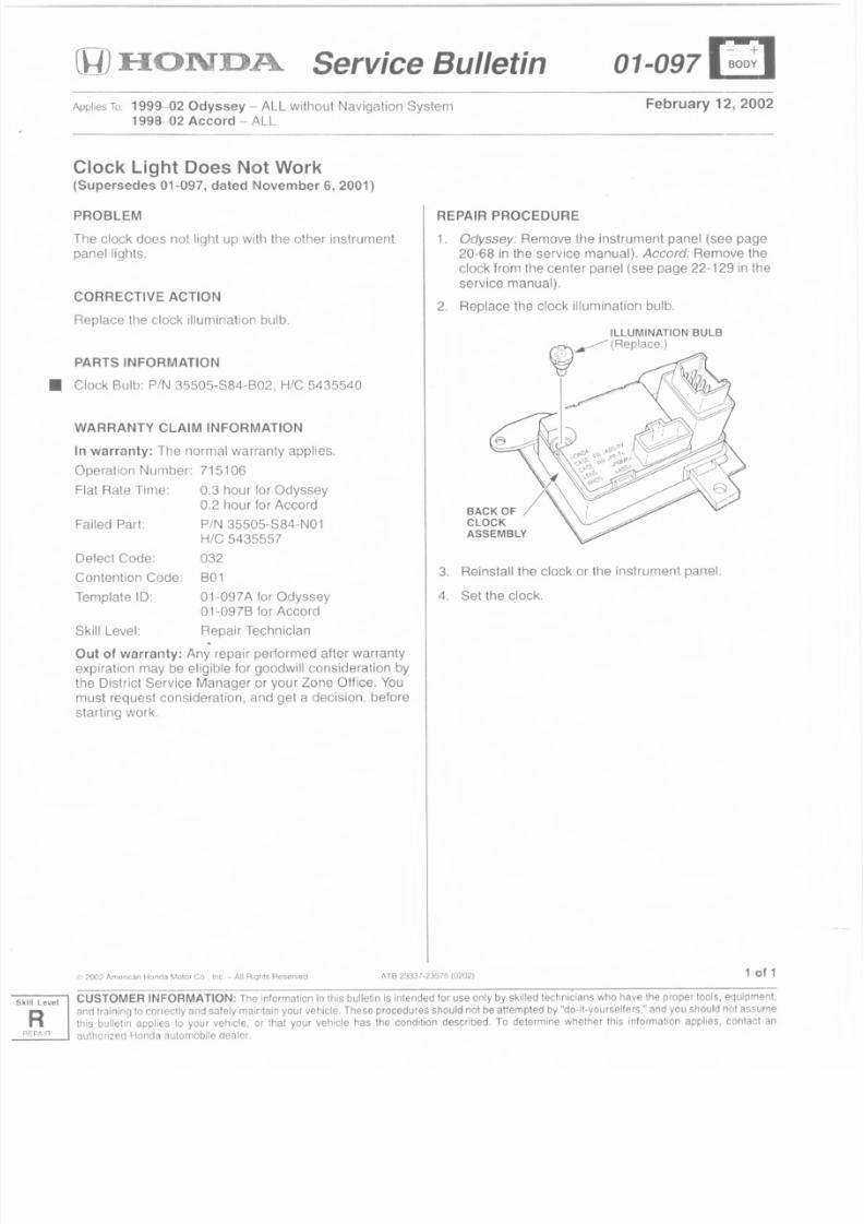
8/2/2019 2002 Honda Odyssey TSB All
http://slidepdf.com/reader/full/2002-honda-odyssey-tsb-all 34/38
(y) :I-IOl\TD.A. Service Bulletin 01-097 [~:-~]
Applies To: 1999-02 Odyssey - ALL without Navigation System
1998-02 Accord - ALL
February 12, 2002
Clock Light Does Not Work(Supersedes 01-097, dated November 6, 2001)
PROBLEM
The clock does not light up with the other instrument
panel lights.
CORRECTIVE ACTION
Replace the clock illumination bulb.
PARTS INFORMATION
• Clock Bulb: PIN 35505-884-802, HIC 5435540
WARRANTY CLAIM INFORMATION
In warranty: Tile normal warranty applies.
Operation Number: 715106
Flat Hate Time: 0.3 hour for Odyssey
0.2 hour for Accord
Failed Part: PIN 35505-884-N01
HIC 5435557
032
B01
01 -097 A for Odyssey
01-097B for Accord
Repair Technician
Defect Code:
Contention Code:
Template 10:
Skill Level: .Out of warranty: Any repair performed after warranty
expiration may be eligible for goodwill consideration by
the District Service Manager or your Zone Office. You
must request consideration, and get a decision, before
starting work.
REPAIR PROCEDURE
1. Odyssey: Remove the instrument panel (see page
20-68 in the service manual). Accord. Remove the
clock from the center panel (see page 22-129 in the
service manual).
2. Replace the clock il lumination bulb
3. Reinstall the clock or the instrument panel.
4. Set the clock.
I.l: 2002 Amer ican Honda MOlor Co , Inc , - A. IIRigh ts neserveo A.lB 23337-23575 (0202) 1 of 1
CUSTOMER INFORMATION: The information in this bul letin is intended for use only by ski lled technicians who have the proper tools , equipment,
and training to correctly and safely maintain your vehicle. These procedures shoutd not be attempted by "do-it-yoursellers," and you should not assume
this bul le tin applies to your vehicle, or that your vehicle has the condition described. To determine whether this information appl ies, contact an
R _, authorized Honda automobile dealer.
Level
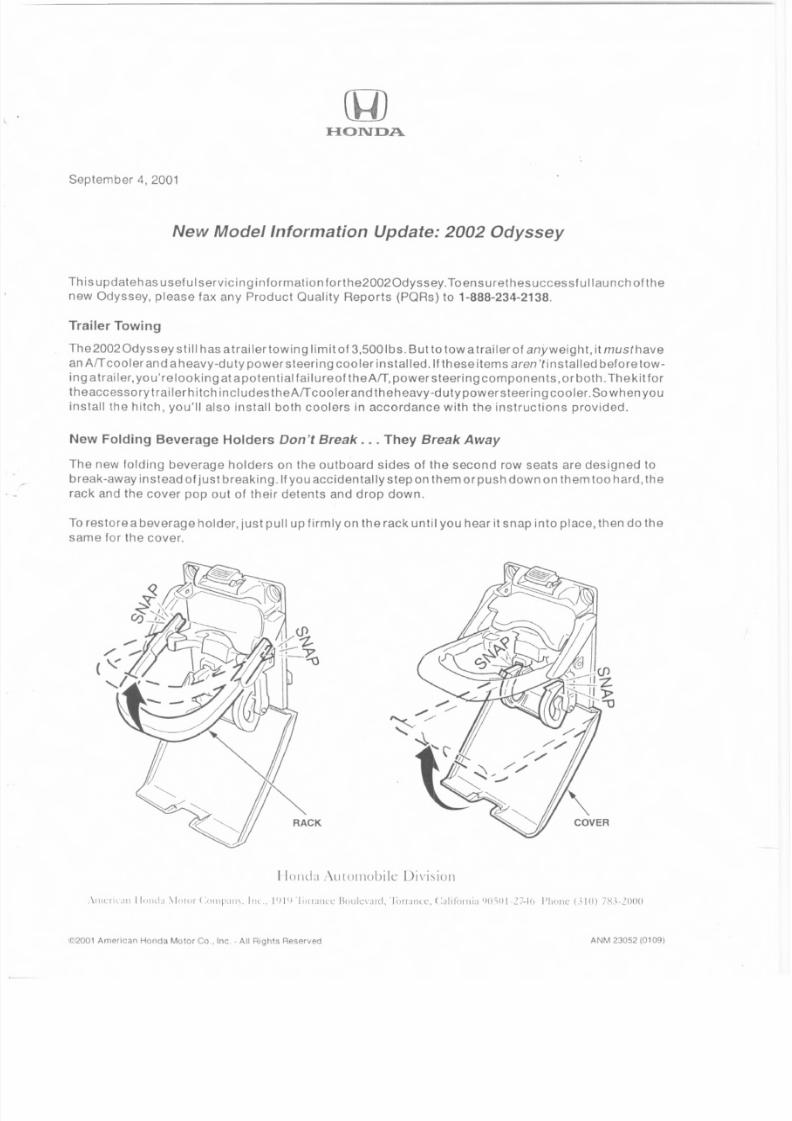
8/2/2019 2002 Honda Odyssey TSB All
http://slidepdf.com/reader/full/2002-honda-odyssey-tsb-all 35/38
HONDA
September 4, 2001
New Model Information Update: 2002 Odyssey
Th is updalehas useful servic in 9 informalio nfar the20020dyssey, Toensurethesuccessfu Ilaunch of the
new Odys sey, p lease fax any Prod uct Oua l ity Repo rts (PO Rs) to 1-888-234-2138,
Trailer Towing
The20020dyssey still has atrailer towing limit of 3,5001bs, But 10 tow a trailer of anyweight, it rnusthave
an ArT cooler and aheavy-duty power steering cooler installed. If these items aren'tinstalled beforetow-
ing atrailer, you'relooking at apotential failureof theArT, powersteering components,orboth. Thekit fortheaccesso ry trail er hi tch inc Iud es theArT coo ler and th eheavy-duty powers teerin 9coo Ier. So wh en you
install the hitch, you'll also install both coolers in accordance with the instructions provided,
New Folding Beverage Holders Don't Break ... They Break Away
The new folding beverage holders on the outboard sides of the second row seats are designed to
break-away instead of just breaking,lfyou accidentally step on Ihemorpushdownon them too hard, the
rack and the cover pop out of their detents and drop down.
To restore a beverage holder, just pull up firmly on the rack until you hear it snap into place, then do the
same for the cover,
[lu nd a A utom ob ile Divis ion
, \' IIL' [I (al l I I"JI lb , \Iolor I :"1111"'11\,nL, I'J I') 'IOIICI"l'~ lIollic\'Jrd, 'lilrr;[IllT, (:alililJllia ' )O'iIJl·!7-i1J I'h')ll~ 0](11 7K\·20IJO
©2001 American Honda Motor Co , Inc .. All Rights Reserved ANM 23052 (0109)
8/2/2019 2002 Honda Odyssey TSB All
http://slidepdf.com/reader/full/2002-honda-odyssey-tsb-all 36/38
Larger Tires Mean Higher Inflation Pressures
Th eli re size 0 n th e 2002 Odyssey has ch anged from 215/6SR 16 to 225/60R 16. Make sura you in flate
these larger tires to 36 psi.
No Seat-Back Heater on EX-L Model
To allow en aug h space fa r th e occ upan t po s it ion detecti 0 n system (OPDS) sen sars. th e EX-L mod el
doesn't come with a heater in the front passenger seat-back. although the seat cushion is heated.
When You Think Oil, Think 5W-20, Not 5W-30
All 2002 Odyssey engines are factory-filled with the new SW-20 grade engine oil to provide high fuel -economy and performance. When servicing, make su re you use onlyth is grade of engine oil, not your _
traditional 5W-30 grade.
Low Fuel Indicated by LED
The low fuel indicator light is now an amber LED instead of the fuel pump icon used on earlier models.
Check Glove Box for Demo DVD
Just areminder: On an EX-L model with the HondaDVD Entertainment System (RearEntertainment Sys-
tem). th ere's ad erno DVD incl uded in the ow ner's rnan ual packet in th eg love box. During POI, make su re
this DVD is loaded into the DVD player for vehicle delivery.
And Speaking of the Honda OVOEntertainment System ...
The flip-down screen for the system is designed to turn itself off when it's pushed beyond the viewing
detent. The wi reles s headphon es wo rk onfywh i Ieseated in the seco ndan d th i rd row seats. Don '(expect
them to work i f you're sitting in the driver's or front passenger's seat or standing outside the vehicle.
Sincerely,
American Honda Motor Co., Inc.
Honda Automobile Division
©2001 American Honda Molor Co., tnc - All Rights Reserved ANM 23052 (0109)
8/2/2019 2002 Honda Odyssey TSB All
http://slidepdf.com/reader/full/2002-honda-odyssey-tsb-all 37/38
(g)HONDA
Odyssey Power Sliding Door System
Customer's concern: "VVlwn lrn clusing one of the sliding doors on m.l' van, the door
stops, beeps three limes, and g(l~S buck the other wav."
OR
"When 1 open the door for the gas tank, the sliding door on my side locks."
What's happening and why: Each of the po\tver sliding doors has the obstacle detection
system, also called the auto-reverse feature or trap detection. If a door meets resistance
or something gels in lhe \vay while it's opening or closing, the system detects a sudden
reduction in dour speed. The system lhen slops the door, beeps three times to alert the
driver to the obstacle in the doors path, and reverses the direction of movement. The
door 11l<JV not i 111 111 cd ialely reverse its direction, however, Z 1S an elevator dour would do.
When vou use the release lever and open the fuel fill door to put fuel in the tank, the
left (driver's side) sliding door Jocks automatically to keep that door from being opened
into till' fuel fill door and possiblv damJging both doors. [f 'lOU alternpt Io unlock the
left sliding door, it will lock Clg,lin. (You could override this automalic lock, however, by
pushing the lock knob to the unlock position and holding it there for several seconds;
the dour could now be operated in its normal automatic modes.) Once you finish
fueling and close the fuel fill dour, the left door does not unlock automatically You
must unlock the door with the lock knob on the inside of the door, with the power door
lock switches, or \vith the remote t ransrni t tcr .
What can be done: because the po\vl'r sliding door could cause bruising or discomfort
while closing, make sure passengers and any objects Z1rE' clear of the door before you
close it . Also, so that the motor can pull the sliding dour all the vvay shut when the door
is about to latch. the auto-reverse Iealure slops working at that point. So make sure that
passengers, especially children, don't have their hands on the edge of the door or on the
door pillar. If ynu notice lhal a person or an object is in the way while a sliding door is
in motion, use the dashboard switches or the remote transmitter to stop the door; the
door handles cannot be used to stop the door once it is in motion.
Further explanation: If you move the shift lever out of Park while a sliding door is
closing, the beeper beeps until the dum is latched. A solid tone when you move the
shift lever out of IJark means that a sliding door is open and is not moving. For more
details, refer to the descri pt ion of the power sliding door system for your vehicle in the
appropriate section of your owner's manual.,
' s ; ) 2001 American Honda Motor Co. Inc - All Rights Reserved Y0472 AJA 20803-22877 (0109)
8/2/2019 2002 Honda Odyssey TSB All
http://slidepdf.com/reader/full/2002-honda-odyssey-tsb-all 38/38
HONDA
June 4, 2002
Dear Service Manager:
Honda Motor Co., LTD. is announcing a Safety Recall campaign for certain 1997-99 Accords,
1998-00 Civics, 1997-99 CR-Vs, 1997-00 Odysseys, and 1997-99 Preludes.
Electrical contacts in the ignition switch can wear prematurely due to high electrical current passing
through the switch. Worn out ignition contacts could cause the engine to stall withoufwarning. Although
the engine will restart in most cases, a vehicle that stalls while driving increases the risk of a crash.
Affected Vehicles
The affected VIN ranges for all three models are very wide, while the number of affected vehicles ismuch smaller. Because of this, you must verify vehicle eligibil ity by making sure the customer has a
notification leiter. Eligibility can be further checked using one of these methods.
• The vehicle is shown as eligible on DCS or iN (Interactive Network) VIN Stalus Inquiry.
• The vehicle is listed on your campaign responsibility report.·
* Campaign responsibility reports will be issued as customer notifications are mailed. Keep all the
reports you receive; an overall report will not be sent 10 you.
Repair Strategy
The repair is to replace the ignition (electrical) switch. For repair information, refer to the enclosed
service bulletin, #02-031, Safety Recal!: Ignition Switch
Reinstalling aftermarket pens (security systems, alarms, audio systems, etc.) connected to the ignition
wiring is not covered under this campaign. If a customer wanls a non-Honda part reinstalled, the shop
that installed the part (or the customer) must do the work and assume liability. In addition, the customer
is responsible for all costs associated with the non-Honda part and its installation. If you have any
questions about this, please contact your District Service Manager.
Customer Notification
We will begin mailing customer notifications in late June. The quantity mailed will depend on the
number of parts available for allocation. Mailings will continue as more parts become available. Itwill
probably lake about three months to complete the mailings.
Parts Information
During the initial stage of the campaign (June, July, and August), parts will be available by
allocation only; no open ordering. You will be notified by DCS or iN when open ordering is
allowed.
Sincerely,
American Honda Motor Co., Inc.
Honda Automobile Division