2381 sinaut lan doku v20 e
TRANSCRIPT
Applikationen & Tools
Answers for industry.
Application for SINAUT ST7 Telecontrol with TIM4R-IE and TIM3V-IE in an Ethernet-based Environment
SINAUT ST7 Telecontrol– Configuration 8– Volume 1
Application Description May 2009

Warranty, Liability and Support
2 SIMATIC NET Configuration 8- Volume 1
V2.0, Entry ID: 23810112
Warranty, Liability and Support
Note The Application Examples are not binding and do not claim to be complete regarding the circuits shown, equipping and any eventuality. The Application Examples do not represent customer-specific solutions. They are only intended to provide support for typical applications. You are responsible for ensuring that the described products are used correctly. These application examples do not relieve you of the responsibility to use sound practices in application, installation, operation and maintenance. When using these Application Examples, you recognize that we cannot be made liable for any damage/claims beyond the liability clause described. We reserve the right to make changes to these Application Examples at any time without prior notice. If there are any deviations between the recommendations provided in these application examples and other Siemens publications – e.g. Catalogues – the contents of the other documents have priority.
We do not accept any liability for the information contained in this document.
Any claims against us – based on whatever legal reason – resulting from the use of the examples, information, programs, engineering and performance data etc., described in this Application Example shall be excluded. Such an exclusion shall not apply in the case of mandatory liability, e.g. under the German Product Liability Act (“Produkthaftungsgesetz”), in case of intent, gross negligence, or injury of life, body or health, guarantee for the quality of a product, fraudulent concealment of a deficiency or breach of a condition which goes to the root of the contract (“wesentliche Vertragspflichten”). The damages for a breach of a substantial contractual obligation are, however, limited to the foreseeable damage, typical for the type of contract, except in the event of intent or gross negligence or injury to life, body or health. The above provisions do not imply a change of the burden of proof to your detriment.
Any form of duplication or distribution of these Application Examples or excerpts hereof is prohibited without the expressed consent of Siemens Industry Sector.
If you have any questions concerning this document please e-mail us to the following address:
Preface
SIMATIC NET Configuration 8- Volume 1 V2.0, Entry ID: 23810112 3
Preface
Objective of the application
The objective of this application is to familiarize beginners, as well as those changing over from classic SINAUT WAN connections, with the Ethernet communication via the TIM3V-IE, TIM4R-IE and EGPRS/ GPRS radio connection via the internet. An integrated demo plant enables you to follow the configuration and adapt it for your own specific requirements.
Main contents of this application
For clarity reasons the range of topics is divided between two documents.
Volume 1 the central station is connected with the Ethernet via a TIM4R-IE, the two stations via a TIM3V-IE.
Volume 2 is based on volume 1 and illustrates how the connections between the central station and the stations are realized via secured EPRS/ GPRS connections via the internet.
Note Volume 2 is available as an extra document on the HTML page.
Topics not covered by this application
The example project contains no technology-relevant program for control or coordinating the drives. It only serves for demonstrating the data exchange between station and central station. It is kept simple on purpose in order to illustrate the correlation between data in the CPUs and the central station.
Structure of this document
The documentation of this application is divided into the following main parts.
Components Description
Application Description This section provides a general overview of the contents. You will learn about the components used (standard hardware and software components and the specially created software).
Principles of Operation and Program structures
This part describes the detailed function processes of the involved hardware and software components, the solution structures and – where useful – the specific implementation of this application. You will need this section to get to know the interaction of the solution components, e.g. if you want to use them as basic elements for your own developments.
Setup, configuration and operation of the application
This part leads you step by step through the structure, important configuration steps, commissioning and operation of the application.
Appendix This part of the documentation provides additional information such as bibliographic references, glossaries, etc.
Preface
4 SIMATIC NET Configuration 8- Volume 1
V2.0, Entry ID: 23810112
Reference to the Automation and Drives Service & Support
This article is from the Internet application portal of the Automation and Drives Service & Support. The following link takes you directly to the download page of this document.
http://support.automation.siemens.com/WW/view/en/23810112
1 Automation Task
1.1 Overview
SIMATIC NET Configuration 8- Volume 1 V2.0, Entry ID: 23810112 5
Co
pyr
igh
t
Sie
me
ns
AG
20
09
All
righ
ts r
ese
rve
d
23
810
112
_SIN
AU
T_L
AN
_D
OK
U_
V2
0_e
.do
c
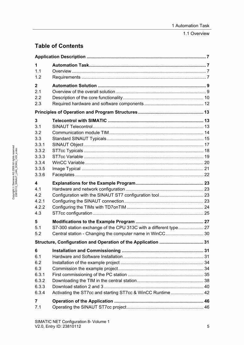
Table of Contents
Application Description ............................................................................................... 7
1 Automation Task............................................................................................. 7 1.1 Overview........................................................................................................... 7 1.2 Requirements ................................................................................................... 7
2 Automation Solution ...................................................................................... 9 2.1 Overview of the overall solution........................................................................ 9 2.2 Description of the core functionality................................................................ 10 2.3 Required hardware and software components ............................................... 12
Principles of Operation and Program Structures .................................................... 13
3 Telecontrol with SIMATIC ............................................................................ 13 3.1 SINAUT Telecontrol........................................................................................ 13 3.2 Communication module TIM........................................................................... 14 3.3 Standard SINAUT Typicals............................................................................. 15 3.3.1 SINAUT Object ............................................................................................... 17 3.3.2 ST7cc Typicals ............................................................................................... 18 3.3.3 ST7cc Variable ............................................................................................... 19 3.3.4 WinCC Variable .............................................................................................. 20 3.3.5 Image Typical ................................................................................................. 21 3.3.6 Faceplates ...................................................................................................... 22
4 Explanations for the Example Program...................................................... 23 4.1 Hardware and network configuration .............................................................. 23 4.2 Configuration with the SINAUT ST7 configuration tool ................................... 23 4.2.1 Configuring the SINAUT connection............................................................... 23 4.2.2 Configuring the TIMs with TD7onTIM ............................................................. 24 4.3 ST7cc configuration ........................................................................................ 25
5 Modifications to the Example Program ...................................................... 27 5.1 S7-300 station exchange of the CPU 313C with a different type.................... 27 5.2 Central station - Changing the computer name in WinCC.............................. 30
Structure, Configuration and Operation of the Application ................................... 31
6 Installation and Commissioning ................................................................. 31 6.1 Hardware and Software Installation................................................................ 31 6.2 Installation of the example project .................................................................. 34 6.3 Commission the example project.................................................................... 34 6.3.1 First commissioning of the PC station ............................................................ 35 6.3.2 Downloading the TIM in the central station..................................................... 38 6.3.3 Download station 2 and 3 ............................................................................... 40 6.3.4 Activating the ST7cc and starting ST7cc & WinCC Runtime.......................... 42
7 Operation of the Application ....................................................................... 46 7.1 Operating the SINAUT ST7cc project ............................................................. 46
1 Automation Task
1.1 Overview
6 SIMATIC NET Configuration 8- Volume 1
V2.0, Entry ID: 23810112
Co
pyr
igh
t
Sie
me
ns
AG
20
09
All
righ
ts r
ese
rve
d
23
810
112
_SIN
AU
T_L
AN
_D
OK
U_
V2
0_e
.do
c
7.2 Subscribers Status.......................................................................................... 47 7.3 Error message list........................................................................................... 49 7.4 Operation 02_Station / 03_Station.................................................................. 49 7.5 Archive............................................................................................................ 53 7.6 SINAUT Diagnostics and Service ................................................................... 53 7.7 Terminate WinCC and ST7cc Runtime........................................................... 54 7.8 Cross-communication between station 2 and station 3 .................................. 55
Appendix and List of Further Literature ................................................................... 56
8 Glossary ........................................................................................................ 56
9 Bibliography.................................................................................................. 57 9.1 Bibliographic References................................................................................ 57 9.2 Internet Links .................................................................................................. 58
10 History ........................................................................................................... 59
1 Automation Task
1.1 Overview
SIMATIC NET Configuration 8- Volume 1 V2.0, Entry ID: 23810112 7
Co
pyr
igh
t
Sie
me
ns
AG
20
09
All
righ
ts r
ese
rve
d
23
810
112
_SIN
AU
T_L
AN
_D
OK
U_
V2
0_e
.do
c
Application Description
Content
Here you will be provided with a quick overview of the automation task as well as its solution. Furthermore, you will learn about the components used (standard hardware and software components).
1 Automation Task
1.1 Overview
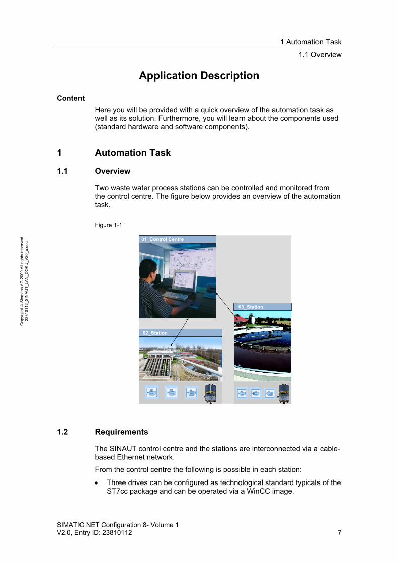
Two waste water process stations can be controlled and monitored from the control centre. The figure below provides an overview of the automation task.
Figure 1-1
02_Station
03_Station
01_Control Centre
1.2 Requirements
The SINAUT control centre and the stations are interconnected via a cable-based Ethernet network.
From the control centre the following is possible in each station:
Three drives can be configured as technological standard typicals of the ST7cc package and can be operated via a WinCC image.
1 Automation Task
1.2 Requirements
8 SIMATIC NET Configuration 8- Volume 1
V2.0, Entry ID: 23810112
Co
pyr
igh
t
Sie
me
ns
AG
20
09
All
righ
ts r
ese
rve
d
23
810
112
_SIN
AU
T_L
AN
_D
OK
U_
V2
0_e
.do
c
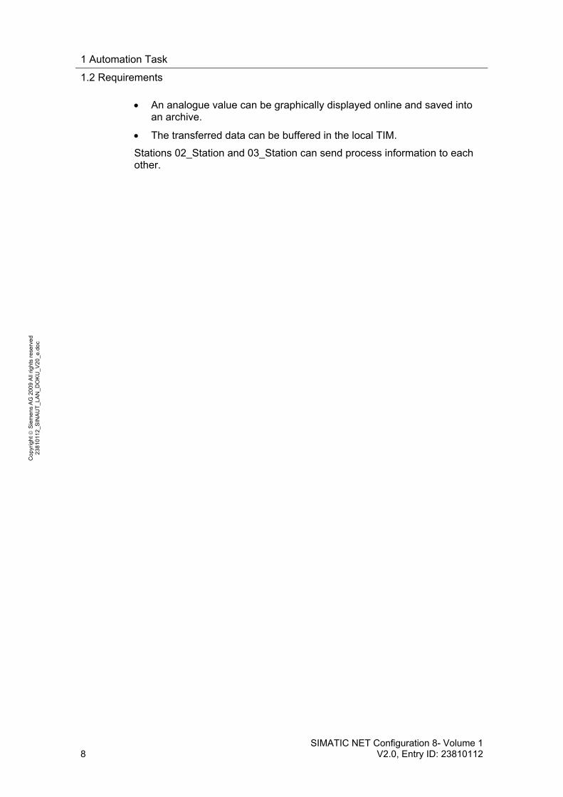
An analogue value can be graphically displayed online and saved into an archive.
The transferred data can be buffered in the local TIM.
Stations 02_Station and 03_Station can send process information to each other.
2 Automation Solution
2.1 Overview of the overall solution
SIMATIC NET Configuration 8- Volume 1 V2.0, Entry ID: 23810112 9
Co
pyr
igh
t
Sie
me
ns
AG
20
09
All
righ
ts r
ese
rve
d
23
810
112
_SIN
AU
T_L
AN
_D
OK
U_
V2
0_e
.do
c
2 Automation Solution
2.1 Overview of the overall solution
A control centre communicates with two stations via Ethernet.
Control centre: PG/PC with SIMATIC NET PC Software, WinCC, SINAUT ST7cc and TIM4R-IE (TD7onTIM)
Ethernet connection: central SCALANCE-X208 switch
Distributed stations: CPU313C with TIM 3V-IE (TD7onTIM)
Schematic layout
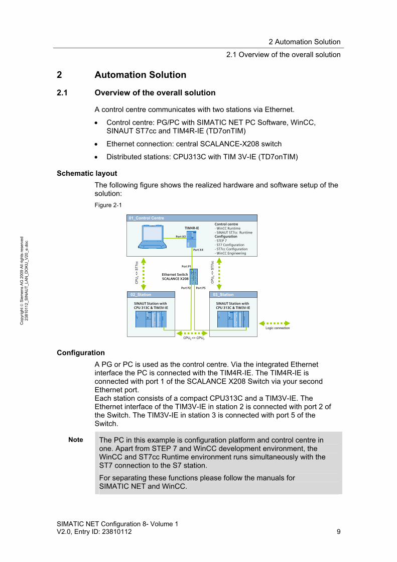
The following figure shows the realized hardware and software setup of the solution:
Figure 2-1
Ethernet SwitchSCALANCE X208
CP
U2
<>
ST
7cc
02_Station
SINAUT Station withCPU 313C & TIM3V-IE
03_Station
SINAUT Station withCPU 313C & TIM3V-IE
01_Control Centre
CPU2 <> CPU3
CP
U3
<>
ST
7cc
TIM4R-IE
Logic connection
Configuration- STEP 7- ST7 Configuration- ST7cc Configuration- WinCC Engineering
Control centre- WinCC Runtime- SINAUT ST7cc Runtime
Port X3
Port X4
Port P1
Port P2 Port P5
Configuration
A PG or PC is used as the control centre. Via the integrated Ethernet interface the PC is connected with the TIM4R-IE. The TIM4R-IE is connected with port 1 of the SCALANCE X208 Switch via your second Ethernet port. Each station consists of a compact CPU313C and a TIM3V-IE. The Ethernet interface of the TIM3V-IE in station 2 is connected with port 2 of the Switch. The TIM3V-IE in station 3 is connected with port 5 of the Switch.
Note The PC in this example is configuration platform and control centre in one. Apart from STEP 7 and WinCC development environment, the WinCC and ST7cc Runtime environment runs simultaneously with the ST7 connection to the S7 station.
For separating these functions please follow the manuals for SIMATIC NET and WinCC.
2 Automation Solution
2.2 Description of the core functionality
10 SIMATIC NET Configuration 8- Volume 1
V2.0, Entry ID: 23810112
Co
pyr
igh
t
Sie
me
ns
AG
20
09
All
righ
ts r
ese
rve
d
23
810
112
_SIN
AU
T_L
AN
_D
OK
U_
V2
0_e
.do
c
Note The power supply (DC 24 V) of the SIMATIC station is used in this test setup also for supplying the other modules (Switch and TIM).
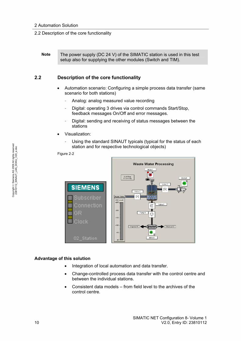
2.2 Description of the core functionality
Automation scenario: Configuring a simple process data transfer (same scenario for both stations)
– Analog: analog measured value recording
– Digital: operating 3 drives via control commands Start/Stop, feedback messages On/Off and error messages.
– Digital: sending and receiving of status messages between the stations
Visualization:
– Using the standard SINAUT typicals (typical for the status of each station and for respective technological objects)
Figure 2-2
Advantage of this solution
Integration of local automation and data transfer.
Change-controlled process data transfer with the control centre and between the individual stations.
Consistent data models – from field level to the archives of the control centre.

2 Automation Solution
2.2 Description of the core functionality
SIMATIC NET Configuration 8- Volume 1 V2.0, Entry ID: 23810112 11
Co
pyr
igh
t
Sie
me
ns
AG
20
09
All
righ
ts r
ese
rve
d
23
810
112
_SIN
AU
T_L
AN
_D
OK
U_
V2
0_e
.do
c
Supplying the archives in the control centre system using the provided time stamps.
High data security through buffering the message frames in the local TIM.
Networkwide clock synchronization (via the SINAUT networks)
2 Automation Solution
2.3 Required hardware and software components
12 SIMATIC NET Configuration 8- Volume 1
V2.0, Entry ID: 23810112
Co
pyr
igh
t
Sie
me
ns
AG
20
09
All
righ
ts r
ese
rve
d
23
810
112
_SIN
AU
T_L
AN
_D
OK
U_
V2
0_e
.do
c
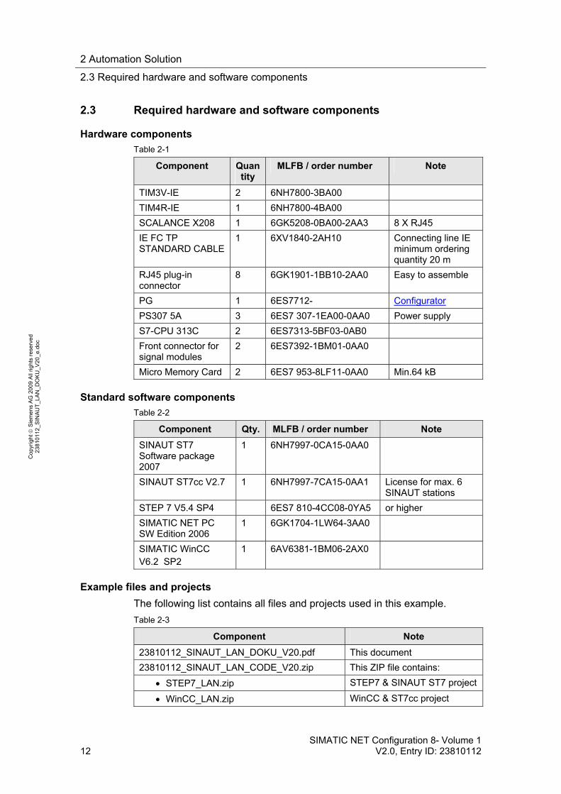
2.3 Required hardware and software components
Hardware components
Table 2-1
Component Quantity
MLFB / order number Note
TIM3V-IE 2 6NH7800-3BA00
TIM4R-IE 1 6NH7800-4BA00
SCALANCE X208 1 6GK5208-0BA00-2AA3 8 X RJ45
IE FC TP STANDARD CABLE
1 6XV1840-2AH10 Connecting line IE minimum ordering quantity 20 m
RJ45 plug-in connector
8 6GK1901-1BB10-2AA0 Easy to assemble
PG 1 6ES7712- Configurator
PS307 5A 3 6ES7 307-1EA00-0AA0 Power supply
S7-CPU 313C 2 6ES7313-5BF03-0AB0
Front connector for signal modules
2 6ES7392-1BM01-0AA0
Micro Memory Card 2 6ES7 953-8LF11-0AA0 Min.64 kB
Standard software components
Table 2-2
Component Qty. MLFB / order number Note
SINAUT ST7 Software package 2007
1 6NH7997-0CA15-0AA0
SINAUT ST7cc V2.7 1 6NH7997-7CA15-0AA1 License for max. 6 SINAUT stations
STEP 7 V5.4 SP4 6ES7 810-4CC08-0YA5 or higher
SIMATIC NET PC SW Edition 2006
1 6GK1704-1LW64-3AA0
SIMATIC WinCC V6.2 SP2
1 6AV6381-1BM06-2AX0
Example files and projects
The following list contains all files and projects used in this example.
Table 2-3
Component Note
23810112_SINAUT_LAN_DOKU_V20.pdf This document
23810112_SINAUT_LAN_CODE_V20.zip This ZIP file contains:
STEP7_LAN.zip STEP7 & SINAUT ST7 project
WinCC_LAN.zip WinCC & ST7cc project
3 Telecontrol with SIMATIC
3.1 SINAUT Telecontrol
SIMATIC NET Configuration 8- Volume 1 V2.0, Entry ID: 23810112 13
Co
pyr
igh
t
Sie
me
ns
AG
20
09
All
righ
ts r
ese
rve
d
23
810
112
_SIN
AU
T_L
AN
_D
OK
U_
V2
0_e
.do
c
Principles of Operation and Program Structures
Content
This chapter discusses the background information on the topic of SINAUT Telecontrol and where appropriate the configurations leading to the example program.
You only need this part if you want to learn about the interaction of the solution components.
3 Telecontrol with SIMATIC
This chapter provides the beginner with a brief overview of the SINAUT Telecontrol system and its manifold possibilities.
3.1 SINAUT Telecontrol
SINAUT ST7 Telecontrol (Siemens Network Automation) is based on SIMATIC S7-300, S7-400 and WinCC. It supplements this system with respective hardware and software, enabling the networking of individual components via WAN (Wide Area Network).
The fully automated monitoring and control of distributed process station, which via various WAN media exchange data between each other and with one or several control centres, is possible.
Under the topic WAN, the SINAUT system provides solutions for data transmission via classic WAN, such as dedicated copper lines, telephone networks, radio etc., but also via modern, Ethernet-technology-based WAN, such as broad-band systems or the internet.
SINAUT ST7cc (the PC control center) server as a control center, basec on WinCC. It is a control center system particularly designed for the event controlled and time-stamped data transmission of the SINAUT system.
The SINAUT software in the stations provides for a change-controlled process data transmission with the control center as well as between the individual CPUs. A particular feature of the TIM data transmission module, which is used in the SINAUT ST7 system, is the local storage of the data messages (including time stamp) during failure of the communication path, dailure of a partner or for cost optimization for dialup networks.
Any diagnostics and programming functions which SIMATIC and SINAUT provide for station automation and SINAUT communication, can be used across the SINAIT networks- even as the process data transmission is ni progress.
Modern remote technology increasingly builds on communication via Ethernet-based LAN and WAN connections. Today, any options outside the classic modem connections (dialup and dedicated line) can be used, from exitsting company LAN networks, Fibreoptic-Long-Distanve connection, to internet connections via DSL (high-speed) and EGPRS.

3 Telecontrol with SIMATIC
3.2 Communication module TIM
14 SIMATIC NET Configuration 8- Volume 1
V2.0, Entry ID: 23810112
Co
pyr
igh
t
Sie
me
ns
AG
20
09
All
righ
ts r
ese
rve
d
23
810
112
_SIN
AU
T_L
AN
_D
OK
U_
V2
0_e
.do
c
3.2 Communication module TIM
This application uses SINAUT ST7. Central component of the SINAUT ST7 hardware is the communication module TIM (Telecontrol Interface Module). They manage the data traffic for the S7-CPU or the control centre PC via WAN.
For SINAUT data communication, the SINAUT TD7 software can be used for the CPU (TD7onCPU) or the block library (TD7onTIM) integrated in the TIM 3V-IE(Advanced). TD7onTIM enables using the smallest S7-CPUs 312 and 312C, as ideally no CPU main memory is required any longer for SINAUT. The figure below summarizes the properties of the TIMs, which are used in this application.
Figure 3-1
Note This chapter does not replace the official documentation. For more information on SINAUT Telecontrol see /1/ and /2/ in the appendix.
The TIM4R-IE is in this application used as stand-alone TIM in the central station.
The application of a TIM 4R-IE as central TIM is in many cases the better solution since it offers the following advantages:
For data transfer via an IP-based WAN the TIM generally provides better preconditions than with the Ethernet card of the PC. Compared
for S7-300
easily ready Module exchange without PG (MMC of the CPU)
For S7-300 and for stand-alone mode (without S7-300 CPU) with S7-400 and PC)
Double width Module exchange
without PG (MMC of the CPU or C-PLUG
Station Master
Node station
Station Master
Node station
General Properties
SINAUT Library
SINAUT Communication via ...
TIM can be used in ...
Data Memory
S7 Connections via IP-based networks
16,000 message frames
32,000 message frames
56,000 message frames, battery
buffered
RS232 or RJ45 RS232 and RJ45 2 x RS232/RJ45 and 2 x RJ45
3 Telecontrol with SIMATIC
3.3 Standard SINAUT Typicals
SIMATIC NET Configuration 8- Volume 1 V2.0, Entry ID: 23810112 15
Co
pyr
igh
t
Sie
me
ns
AG
20
09
All
righ
ts r
ese
rve
d
23
810
112
_SIN
AU
T_L
AN
_D
OK
U_
V2
0_e
.do
c
with LAN, for example, the data transfer in IP-based WAN is often more prone to failure and the response times are partly longer. The TIM can be adjusted ideally to the respective network behavior via various parameters.
For the PC of the control center the central TIM reduces the number of S7 connections, which the PC otherwise must store during direct connection with stations via an IP-based network, to only one connection.
The TIM separates the local Ethernet from the IP-based networks to the stations. Only SINAUT and PG communication with the stations can pass. This prevents unnecessary traffic in the often non-broadband WAN.
For a redundant control center the central TIM employed there provides for the reduction of the data volume in the WAN. This way the TIM reduces the costs for networks with volume tariffs, for example GPRS. If the stations were directly connected to the redundant control center (without central TIM), then it would send each message frame twice to supply both control center PCs with data. During application of a central TIM the stations send their telegrams only once. The message frames for supplying both PCs are then doubled by the central TIM.
3.3 Standard SINAUT Typicals
To support the user in engineering his plant, he is provided with sample engineering templates for frequently used technical objects, e.g. motors, pumps, valves. These templates can be integrated into an HMI software and therefore represent an image of the real object.
For SINAUT an engineering template of a technological object consists of one or several image typicals, a faceplate and one or several ST7cc typicals.
The definitions for bits controlling or visualizing (information units) the templates are default.
Overview
For SINAUT the configuration of technical objects ranges across several levels.
Automation level
Communication level
Control level

3 Telecontrol with SIMATIC
3.3 Standard SINAUT Typicals
16 SIMATIC NET Configuration 8- Volume 1
V2.0, Entry ID: 23810112
Co
pyr
igh
t
Sie
me
ns
AG
20
09
All
righ
ts r
ese
rve
d
23
810
112
_SIN
AU
T_L
AN
_D
OK
U_
V2
0_e
.do
c
Figure 3-2
Table 3-1
Level Description
For the local CPU, the TIM with TD7onTIM sends and receives the process data using SINAUT objects. Data to be sent by TD7onTIM, are read from the CPU by the TIM via the backplane bus, received data are written to the CPU. (In the CPU no SINAUT blocks are required)
Au
tom
atio
n le
vel
The user program reads the data from the process, processes the data received by the TIM and controls the process. Furthermore, data are read from the process.
The SINAUT message frames are received by the central TIM station which forwards it to ST7cc. They are coded or decoded using the ST7cc typicals, and the data are mapped to the respective ST7cc variables. A ST7cc typical consists of several ST7cc variables.
Co
ntr
ol l
evel
The ST7cc variables are mapped to WinCC variables which are the information carriers for the image typicals and faceplates.
Information unit
All states which a technical object can take on are divided into three information units

3 Telecontrol with SIMATIC
3.3 Standard SINAUT Typicals
SIMATIC NET Configuration 8- Volume 1 V2.0, Entry ID: 23810112 17
Co
pyr
igh
t
Sie
me
ns
AG
20
09
All
righ
ts r
ese
rve
d
23
810
112
_SIN
AU
T_L
AN
_D
OK
U_
V2
0_e
.do
c
The information unit Status for input of all statuses of a technical object, which do not represent a failure, e.g. status ON, Off Automatic Operation
The information unit Alarm for input of all statuses of a technical object which indicate a failure or an urgently to be transmitted status, for example the statuses Control Error, Over Temperature
The information unit Command for output of commands to a technical object, e.g. ON, OFF
3.3.1 SINAUT Object
TIM modules, which are TD7onTIM capable take on any tasks for the local CPU using the SINAUT objects, in order to reduce the main memory of the CPU. SINAUT objects consist of
System objects
Data objects
System objects provide system-relevant information to the user program in the CPU. The following table shows the system objects.
Table 3-2
System object Description
WatchDog Indicates to the CPU program whether the communication between CPU and TIM is still working
PartnerStatus Indicates to the CPU program whether the communication with its partners (e.g. ST7cc control center or CPU) is working or failed.
OpInputMonitor Indicates to the CPU program the status of operating inputs
Sending and receiving of process data is configured using standardized data objects. According to the two transmission directions they are divided into:
Data objects for recording and sending of data (ending S for Send)
Data objects for receiving and output of data (ending R for Receive)
SINAUT offers data objects with different data ranges. Each data object may contain one or several send or receive channels. Data object Bin04B_S, for example, contains four send channels for sending four bytes, the data object Cmd01B_R a channel for receiving one byte.
Management and configuration of data objects for the TIM occurs via the ST7 configuration tool. The data objects of the TIM can be added via a standard library. Configuring the data objects occurs in two parts:
Establishing the base parameters of the data objects (e.g. partner, to which the data of the object is sent or from which it is received)
3 Telecontrol with SIMATIC
3.3 Standard SINAUT Typicals
18 SIMATIC NET Configuration 8- Volume 1
V2.0, Entry ID: 23810112
Co
pyr
igh
t
Sie
me
ns
AG
20
09
All
righ
ts r
ese
rve
d
23
810
112
_SIN
AU
T_L
AN
_D
OK
U_
V2
0_e
.do
c
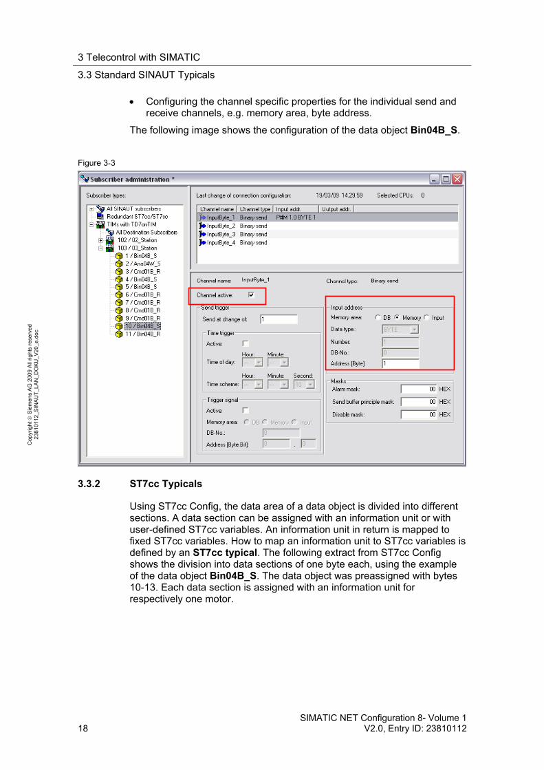
Configuring the channel specific properties for the individual send and receive channels, e.g. memory area, byte address.
The following image shows the configuration of the data object Bin04B_S.
Figure 3-3
3.3.2 ST7cc Typicals
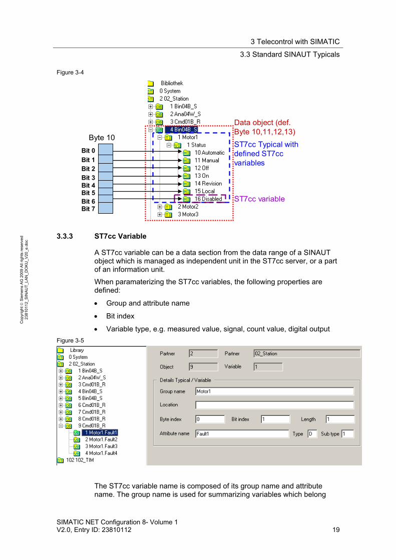
Using ST7cc Config, the data area of a data object is divided into different sections. A data section can be assigned with an information unit or with user-defined ST7cc variables. An information unit in return is mapped to fixed ST7cc variables. How to map an information unit to ST7cc variables is defined by an ST7cc typical. The following extract from ST7cc Config shows the division into data sections of one byte each, using the example of the data object Bin04B_S. The data object was preassigned with bytes 10-13. Each data section is assigned with an information unit for respectively one motor.
3 Telecontrol with SIMATIC
3.3 Standard SINAUT Typicals
SIMATIC NET Configuration 8- Volume 1 V2.0, Entry ID: 23810112 19
Co
pyr
igh
t
Sie
me
ns
AG
20
09
All
righ
ts r
ese
rve
d
23
810
112
_SIN
AU
T_L
AN
_D
OK
U_
V2
0_e
.do
c
Figure 3-4
Data object (def. Byte 10,11,12,13)
ST7cc Typical withdefined ST7ccvariables
ST7cc variable
Bit 0
Bit 1Bit 2Bit 3Bit 4Bit 5Bit 6Bit 7
Byte 10
3.3.3 ST7cc Variable
A ST7cc variable can be a data section from the data range of a SINAUT object which is managed as independent unit in the ST7cc server, or a part of an information unit.
When paramaterizing the ST7cc variables, the following properties are defined:
Group and attribute name
Bit index
Variable type, e.g. measured value, signal, count value, digital output
Figure 3-5
The ST7cc variable name is composed of its group name and attribute name. The group name is used for summarizing variables which belong
3 Telecontrol with SIMATIC
3.3 Standard SINAUT Typicals
20 SIMATIC NET Configuration 8- Volume 1
V2.0, Entry ID: 23810112
Co
pyr
igh
t
Sie
me
ns
AG
20
09
All
righ
ts r
ese
rve
d
23
810
112
_SIN
AU
T_L
AN
_D
OK
U_
V2
0_e
.do
c
together and manage them in the WinCC Tag Management in a group. The attribute name serves for identification of the variables.
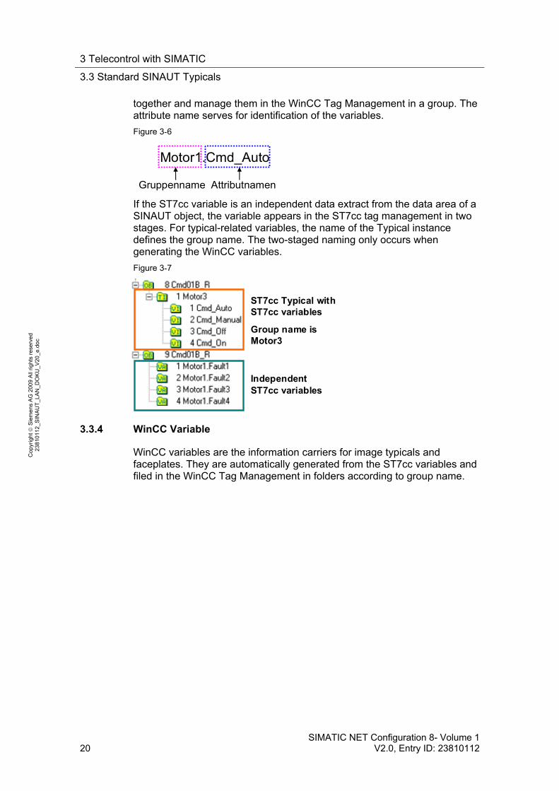
Figure 3-6
Motor1.Cmd_Auto
Gruppenname Attributnamen
If the ST7cc variable is an independent data extract from the data area of a SINAUT object, the variable appears in the ST7cc tag management in two stages. For typical-related variables, the name of the Typical instance defines the group name. The two-staged naming only occurs when generating the WinCC variables.
Figure 3-7
IndependentST7cc variables
ST7cc Typical withST7cc variables
Group name is Motor3
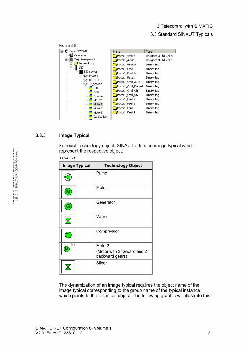
3.3.4 WinCC Variable
WinCC variables are the information carriers for image typicals and faceplates. They are automatically generated from the ST7cc variables and filed in the WinCC Tag Management in folders according to group name.
3 Telecontrol with SIMATIC
3.3 Standard SINAUT Typicals
SIMATIC NET Configuration 8- Volume 1 V2.0, Entry ID: 23810112 21
Co
pyr
igh
t
Sie
me
ns
AG
20
09
All
righ
ts r
ese
rve
d
23
810
112
_SIN
AU
T_L
AN
_D
OK
U_
V2
0_e
.do
c
Figure 3-8
3.3.5 Image Typical
For each technology object, SINAUT offers an image typical which represent the respective object.
Table 3-3
Image Typical Technology Object
Pump
Motor1
Generator
Valve
Compressor
Motor2 (Motor with 2 forward and 2 backward gears)
Slider
The dynamization of an image typical requires the object name of the image typical corresponding to the group name of the typical instance which points to the technical object. The following graphic will illustrate this:
3 Telecontrol with SIMATIC
3.3 Standard SINAUT Typicals
22 SIMATIC NET Configuration 8- Volume 1
V2.0, Entry ID: 23810112
Co
pyr
igh
t
Sie
me
ns
AG
20
09
All
righ
ts r
ese
rve
d
23
810
112
_SIN
AU
T_L
AN
_D
OK
U_
V2
0_e
.do
c
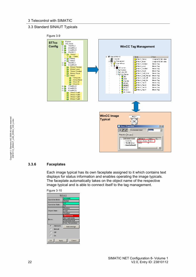
Figure 3-9
ST7cc Config WinCC Tag Management
WinCC Image Typical
3.3.6 Faceplates
Each image typical has its own faceplate assigned to it which contains text displays for status information and enables operating the image typicals. The faceplate automatically takes on the object name of the respective image typical and is able to connect itself to the tag management.
Figure 3-10
4 Explanations for the Example Program
4.1 Hardware and network configuration
SIMATIC NET Configuration 8- Volume 1 V2.0, Entry ID: 23810112 23
Co
pyr
igh
t
Sie
me
ns
AG
20
09
All
righ
ts r
ese
rve
d
23
810
112
_SIN
AU
T_L
AN
_D
OK
U_
V2
0_e
.do
c
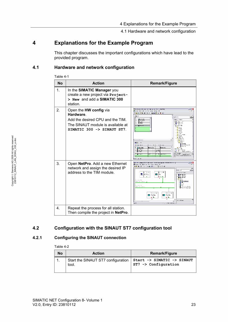
4 Explanations for the Example Program
This chapter discusses the important configurations which have lead to the provided program.
4.1 Hardware and network configuration
Table 4-1
No Action Remark/Figure
1. In the SIMATIC Manager you create a new project via Project-> New and add a SIMATIC 300 station.
2. Open the HW config via Hardware. Add the desired CPU and the TIM. The SINAUT module is available at SIMATIC 300 -> SINAUT ST7.
3. Open NetPro. Add a new Ethernet network and assign the desired IP address to the TIM module.
4. Repeat the process for all station. Then compile the project in NetPro.
4.2 Configuration with the SINAUT ST7 configuration tool
4.2.1 Configuring the SINAUT connection
Table 4-2
No Action Remark/Figure
1. Start the SINAUT ST7 configuration tool.
Start -> SIMATIC -> SINAUT ST7 -> Configuration

4 Explanations for the Example Program
4.2 Configuration with the SINAUT ST7 configuration tool
24 SIMATIC NET Configuration 8- Volume 1
V2.0, Entry ID: 23810112
Co
pyr
igh
t
Sie
me
ns
AG
20
09
All
righ
ts r
ese
rve
d
23
810
112
_SIN
AU
T_L
AN
_D
OK
U_
V2
0_e
.do
c
No Action Remark/Figure
2. Select Connection Configuration and start with OK
3. The right-hand window pane displays the possible connections. Select the desired connection via Right mouse button -> Add.
Save this configuration and change to Subscriber Administration.
4.2.2 Configuring the TIMs with TD7onTIM
Table 4-3
No Action Remark/Figure
1. All SINAUT stations (CPUs, TIMs, SINAUT ST7cc PC) are listed. They have the option of changing the SINAUT station number. Select the desired station. Right mouse button -> Change subscriber No.
Subsequently you enter the new station number.
2. In Subscriber Administration the TD7onTIM stations are configured. Select the TIM you wish to configure from the left window pane. Then click on the TD7onTIM library symbol.
3. A window with the TD7onTIM Library opens. Select the object you wish to configure and click on Paste into Project. Close the library with the Close button.
4 Explanations for the Example Program
4.3 ST7cc configuration
SIMATIC NET Configuration 8- Volume 1 V2.0, Entry ID: 23810112 25
Co
pyr
igh
t
Sie
me
ns
AG
20
09
All
righ
ts r
ese
rve
d
23
810
112
_SIN
AU
T_L
AN
_D
OK
U_
V2
0_e
.do
c
No Action Remark/Figure
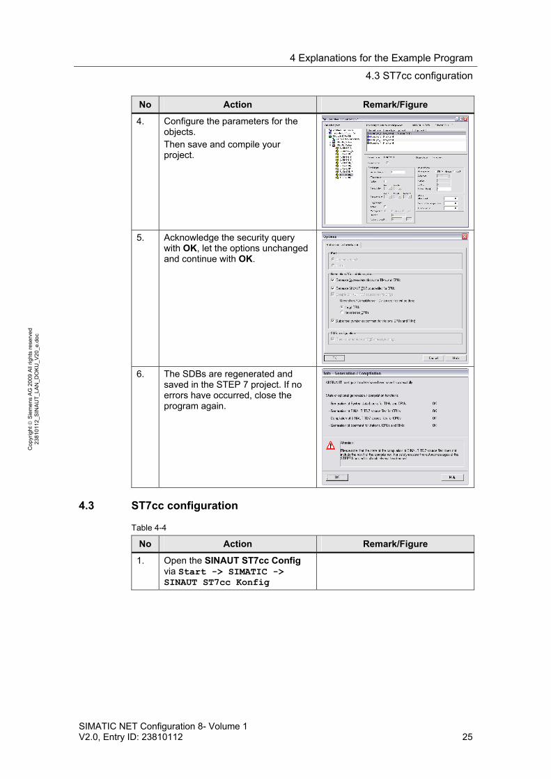
4. Configure the parameters for the objects. Then save and compile your project.
5. Acknowledge the security query with OK, let the options unchanged and continue with OK.
6. The SDBs are regenerated and saved in the STEP 7 project. If no errors have occurred, close the program again.
4.3 ST7cc configuration
Table 4-4
No Action Remark/Figure
1. Open the SINAUT ST7cc Config via Start -> SIMATIC -> SINAUT ST7cc Konfig
4 Explanations for the Example Program
4.3 ST7cc configuration
26 SIMATIC NET Configuration 8- Volume 1
V2.0, Entry ID: 23810112
Co
pyr
igh
t
Sie
me
ns
AG
20
09
All
righ
ts r
ese
rve
d
23
810
112
_SIN
AU
T_L
AN
_D
OK
U_
V2
0_e
.do
c
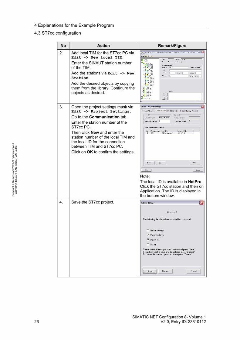
No Action Remark/Figure
2. Add local TIM for the ST7cc PC via Edit -> New local TIM
Enter the SINAUT station number of the TIM. Add the stations via Edit -> New Station
Add the desired objects by copying them from the library. Configure the objects as desired.
3. Open the project settings mask via Edit -> Project Settings.
Go to the Communication tab. Enter the station number of the ST7cc PC. Then click New and enter the station number of the local TIM and the local ID for the connection between TIM and ST7cc PC. Click on OK to confirm the settings.
Note: The local ID is available in NetPro. Click the ST7cc station and then on Application. The ID is displayed in the bottom window.
4. Save the ST7cc project.
5 Modifications to the Example Program
5.1 S7-300 station exchange of the CPU 313C with a different type
SIMATIC NET Configuration 8- Volume 1 V2.0, Entry ID: 23810112 27
Co
pyr
igh
t
Sie
me
ns
AG
20
09
All
righ
ts r
ese
rve
d
23
810
112
_SIN
AU
T_L
AN
_D
OK
U_
V2
0_e
.do
c
5 Modifications to the Example Program
The entire demo-project can be adjusted to your requirements. Performing all of the change options, however, is beyond the scope of this configuration. For further information please refer to the manuals.
5.1 S7-300 station exchange of the CPU 313C with a different type
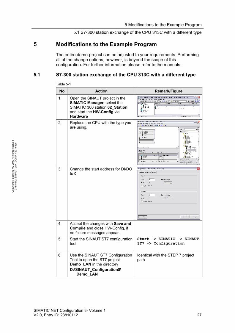
Table 5-1
No Action Remark/Figure
1. Open the SINAUT project in the SIMATIC Manager, select the SIMATIC 300 station 02_Station and start the HW-Config via Hardware
2. Replace the CPU with the type you are using.
3. Change the start address for DI/DO
to 0
4. Accept the changes with Save and Compile and close HW-Config, if no failure messages appear.
5. Start the SINAUT ST7 configuration tool.
Start -> SIMATIC -> SINAUT ST7 -> Configuration
6. Use the SINAUT ST7 Configuration Tool to open the ST7 project Demo_LAN in the directory D:\SINAUT_Configuration8\ Demo_LAN
Identical with the STEP 7 project path

5 Modifications to the Example Program
5.1 S7-300 station exchange of the CPU 313C with a different type
28 SIMATIC NET Configuration 8- Volume 1
V2.0, Entry ID: 23810112
Co
pyr
igh
t
Sie
me
ns
AG
20
09
All
righ
ts r
ese
rve
d
23
810
112
_SIN
AU
T_L
AN
_D
OK
U_
V2
0_e
.do
c
No Action Remark/Figure
7. Select Connection Configuration and start with OK
8. If the connections on the left side are marked red, restore the connection with Right mouse-button -> Recover lost connections.
9. Select the connection which must be restored, clock on Recover connections and confirm with OK. Then you save the new connection table with the save icon or with SINAUT ->Save.
10. Acknowledge the security query with OK, let the options unchanged and continue with OK.
11. The SDBs are regenerated and saved in the STEP 7 project. If no errors have occurred, close the program again.
5 Modifications to the Example Program
0
SIMATIC NET Configuration 8- Volume 1 V2.0, Entry ID: 23810112 29
Co
pyr
igh
t
Sie
me
ns
AG
20
09
All
righ
ts r
ese
rve
d
23
810
112
_SIN
AU
T_L
AN
_D
OK
U_
V2
0_e
.do
c
No Action Remark/Figure
12. Then you transfer the changed SDBs into the CPU, as described in chapter 6.3.2 Loading station 2 and 3.
5 Modifications to the Example Program
5.2 Central station - Changing the computer name in WinCC
30 SIMATIC NET Configuration 8- Volume 1
V2.0, Entry ID: 23810112
Co
pyr
igh
t
Sie
me
ns
AG
20
09
All
righ
ts r
ese
rve
d
23
810
112
_SIN
AU
T_L
AN
_D
OK
U_
V2
0_e
.do
c
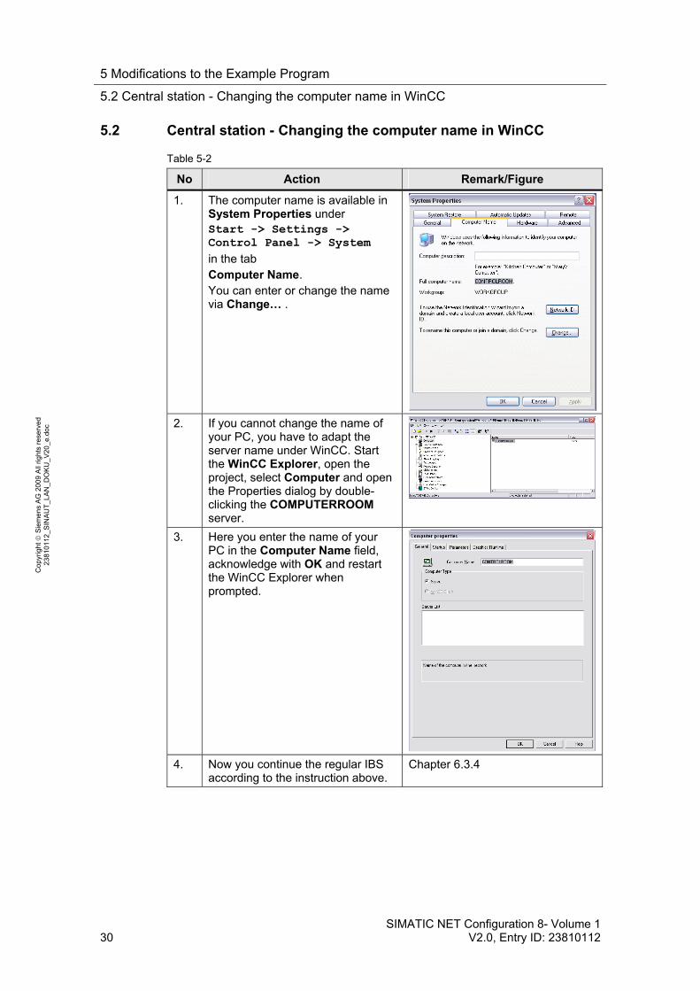
5.2 Central station - Changing the computer name in WinCC
Table 5-2
No Action Remark/Figure
1. The computer name is available in System Properties under Start -> Settings -> Control Panel -> System
in the tab Computer Name. You can enter or change the name via Change… .
2. If you cannot change the name of your PC, you have to adapt the server name under WinCC. Start the WinCC Explorer, open the project, select Computer and open the Properties dialog by double-clicking the COMPUTERROOM server.
3. Here you enter the name of your PC in the Computer Name field, acknowledge with OK and restart the WinCC Explorer when prompted.
4. Now you continue the regular IBS according to the instruction above.
Chapter 6.3.4

6 Installation and Commissioning
6.1 Hardware and Software Installation
SIMATIC NET Configuration 8- Volume 1 V2.0, Entry ID: 23810112 31
Co
pyr
igh
t
Sie
me
ns
AG
20
09
All
righ
ts r
ese
rve
d
23
810
112
_SIN
AU
T_L
AN
_D
OK
U_
V2
0_e
.do
c
Structure, Configuration and Operation of the Application
For startup we offer you a finished STEP 7 / SINAUT example project as a download. This software example supports you in the first steps and tests with this configuration. It enables a quick function test of hardware and software interfaces between the here described products.
The software example is always assigned to the components used in this configuration and shows their principal interaction. However, it is not a real application in the sense of technological problem solving with definable properties.
6 Installation and Commissioning
6.1 Hardware and Software Installation
The following chapters take you step by step through the installation. Furthermore the commissioning of the example projects is described. Figure 6-1
Ethernet SwitchSCALANCE X208
CP
U2
<>
ST
7cc
02_Station
SINAUT Station withCPU 313C & TIM3V-IE
03_Station
SINAUT Station withCPU 313C & TIM3V-IE
01_Control Centre
CPU2 <> CPU3
CP
U3
<>
ST
7cc
TIM4R-IE
LogicConnection
Configuration- STEP 7- ST7 Configuration- ST7cc Configuration- WinCC Engineering
Control Center- WinCC Runtime- SINAUT ST7cc Runtime
Port X3
Port X4
Port P1
Port P2 Port P5
.2
.20
.30
.2
.1
Subnet: 192.168.4.0
Subnet: 192.168.3.0
The following table includes the overview of all IP addresses used in this example. A fixed assignment of the IP addresses is assumed.
Table 6-1
Component IP Address Description
ST7cc computer
192.168.4.2 Central station
TIM4R-IE 192.168.4.1 Central TIM, Ethernet Port X3

6 Installation and Commissioning
6.1 Hardware and Software Installation
32 SIMATIC NET Configuration 8- Volume 1
V2.0, Entry ID: 23810112
Co
pyr
igh
t
Sie
me
ns
AG
20
09
All
righ
ts r
ese
rve
d
23
810
112
_SIN
AU
T_L
AN
_D
OK
U_
V2
0_e
.do
c
Component IP Address Description
TIM4R-IE 192.168.3.2 Central TIM, Ethernet Port X4
TIM3V-IE Station 2
192.168.3.20 TIM in Station 2
TIM3V-IE Station 3
192.168.3.30 TIM in Station 3
The subnet mask in all network components is 255.255.255.0.
Note If you use a PG with LAN and WLAN adapter, assign different IP addresses to the two interfaces. Disable the WLAN interface for the time being.
Installation of the hardware
For details on the hardware components, please see section 2.3. To set up the hardware, please follow the instructions in the below table:
Table 6-2
No Action Comment
1. Preassembled PG or appropriately equipped PC with MS WINDOWS XP SP2 and Ethernet interface
Please follow the respective operating instructions and installation instructions
2. Mount the voltage supply The SIMATIC PS307 can here supply all required modules.
3. Install TIM4V-IE Connect voltage supply
Connect computer with port X3 of the TIM4R-IE
4. Installing CPU313C Adjust backplane bus adapter for TIM
Connect voltage supply
Plug the MMC
If I/O module required, supply with voltage, here DI16/DO16 L+ : 1, 21, 31 M : 20, 30, 40
Manual CPU313C see /5/ in the Appendix
5. Install TIM3V-IE Connect voltage supply
6. Repeat step 4 and 5 for Station_03
7. Install SCALANCE X208 Connect voltage supply
Connect port 1 with Port X4 of the TIM4R-IE
Connect port 2 with the TIM3V-IE of Station 2
Connect port 5 with the

6 Installation and Commissioning
6.1 Hardware and Software Installation
SIMATIC NET Configuration 8- Volume 1 V2.0, Entry ID: 23810112 33
Co
pyr
igh
t
Sie
me
ns
AG
20
09
All
righ
ts r
ese
rve
d
23
810
112
_SIN
AU
T_L
AN
_D
OK
U_
V2
0_e
.do
c
No Action Comment
TIM3V-IE of Station 3
8. Switch on the system.
Installing the software
During generating the application a computer was used as programming computer as well as central station. When using separate computers then the following software must be installed on the central station:
SINAUT ST7cc V2.7
SIMATIC WinCC Runtime V6.2 SP2
SIMATIC NET PC Software Edition 2006
Table 6-3
No Action Comment
1. Installation of STEP 7 V5.4 SP4 You can select the typical configuration
2. Install the SIMATIC NET PC software Edition 2006 Install all suggested software packages. The installation is only possible if STEP 7 has already been installed. In „Service& Support news“ (see \1\ in the appendix) you find information on the released versions.
3. Install the SINAUT ST7 standard software package 2007
SINAUT ST7 Configuration V4.1 SINAUT TD7 Library V2.2.1 Installation is possible if STEP 7 has already been installed.
4. Prior to installing WinCC, some auxiliary programs must still be installed.
Please follow the installation notes for WinCC
5. Install SQL Server 2005 SP1
6. Install MS Windows Hotfix XP SP2 KB319740 MS Tools CD
7. Activate the MS Message Queuing Via Start -> Settings -> Control Panel ->Add or Remove Programs -> Add/Remove Windows Components you select
Message Queuing. For more information click the Details button. Activate Common and start the installation with OK.
8. Install WinCC V6.2 SP2 You can select the typical configuration. In Service& Support news \1\ you find information on the
6 Installation and Commissioning
6.2 Installation of the example project
34 SIMATIC NET Configuration 8- Volume 1
V2.0, Entry ID: 23810112
Co
pyr
igh
t
Sie
me
ns
AG
20
09
All
righ
ts r
ese
rve
d
23
810
112
_SIN
AU
T_L
AN
_D
OK
U_
V2
0_e
.do
c
No Action Comment
released versions.
9. Install ST7cc
Note It is also important to read the descriptions, manuals and any delivery information supplied with the products.
6.2 Installation of the example project
Table 6-4
No Action Comment
1. Unzip the file 23810112_SINAUT_LAN_CODE_V20.zip
The directory D:\SINAUT_Configuration8 is used below as project directory.
2. Unzip the file WinCC_ LAN.zip The WinCC project is now filed at D:\SINAUT_Configuration8\ WinCC_LAN \Demo_TIM3V-IE.MCP
3. Start STEP 7 and retrieve STEP7_ LAN.zip to D:\SINAUT_Configuration8
The STEP 7 project is now filed at D:\SINAUT_Configuration8\Demo_LAN
6.3 Commission the example project
Commissioning of the example project can only occur in the following steps:
1. First startup of the PC station (chapter 6.3.1)
2. Downloading the TIM in the central station (chapter 6.3.2)
3. Downloading station 2 and 3 (chapter 6.3.3)
4. Activating the ST7cc and starting ST7cc & WinCC Runtime (chapter 7.3.4)
6 Installation and Commissioning
6.3 Commission the example project
SIMATIC NET Configuration 8- Volume 1 V2.0, Entry ID: 23810112 35
Co
pyr
igh
t
Sie
me
ns
AG
20
09
All
righ
ts r
ese
rve
d
23
810
112
_SIN
AU
T_L
AN
_D
OK
U_
V2
0_e
.do
c
6.3.1 First commissioning of the PC station
A “PC station” is a PC with communication modules and software components within an automation solution with SIMATIC.
The hardware configuration of a PC station in SIMATIC is comparable with that of an S7 station. Components of a PC station such as modules or software interfaces are assigned to a virtual slot and parameterized in the same way.
Assigning IP address of the PG
Table 6-5
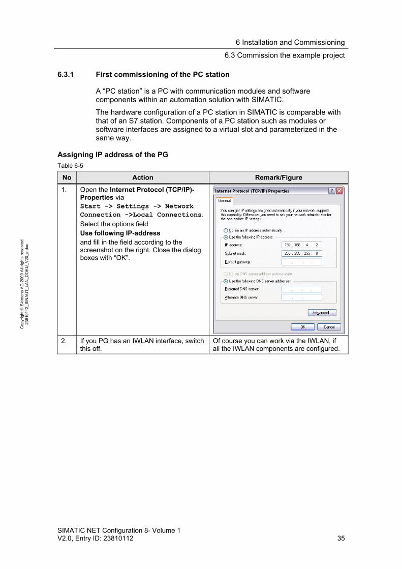
No Action Remark/Figure
1. Open the Internet Protocol (TCP/IP)-Properties via Start -> Settings -> Network Connection ->Local Connections.
Select the options field Use following IP-address and fill in the field according to the screenshot on the right. Close the dialog boxes with “OK”.
2. If you PG has an IWLAN interface, switch this off.
Of course you can work via the IWLAN, if all the IWLAN components are configured.
6 Installation and Commissioning
6.3 Commission the example project
36 SIMATIC NET Configuration 8- Volume 1
V2.0, Entry ID: 23810112
Co
pyr
igh
t
Sie
me
ns
AG
20
09
All
righ
ts r
ese
rve
d
23
810
112
_SIN
AU
T_L
AN
_D
OK
U_
V2
0_e
.do
c
Import PC station
Table 6-6
No Action Remark/Figure
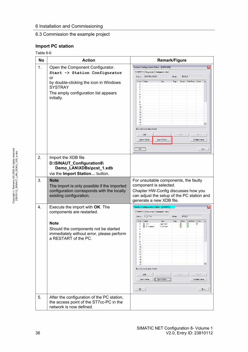
1. Open the Component Configurator. Start -> Station Configurator or by double-clicking the icon in Windows SYSTRAY The empty configuration list appears initially.
2. Import the XDB file D:\SINAUT_Configuration8\ Demo_LAN\XDBs\pcst_1.xdb via the Import Station… button.
3. Note The import is only possible if the imported configuration corresponds with the locally existing configuration.
For unsuitable components, the faulty component is selected. Chapter HW-Config discusses how you can adjust the setup of the PC station and generate a new XDB file.
4. Execute the import with OK. The components are restarted. Note Should the components not be started immediately without error, please perform a RESTART of the PC.
5. After the configuration of the PC station, the access point of the ST7cc-PC in the network is now defined.
6 Installation and Commissioning
6.3 Commission the example project
SIMATIC NET Configuration 8- Volume 1 V2.0, Entry ID: 23810112 37
Co
pyr
igh
t
Sie
me
ns
AG
20
09
All
righ
ts r
ese
rve
d
23
810
112
_SIN
AU
T_L
AN
_D
OK
U_
V2
0_e
.do
c
Specifying access points
Table 6-7
No Action Remark/Figure
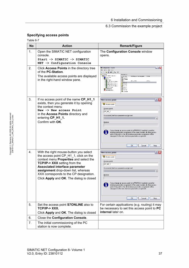
1. Open the SIMATIC NET configuration console. Start -> SIMATIC -> SIMATIC NET -> Configuration Console
The Configuration Console window opens.
2. Click Access Points in the directory tree of the PC-Station. The available access points are displayed in the right-hand window pane.
3. If no access point of the name CP_H1_1 exists, then you generate it by opening the context menu New -> New access Point in the Access Points directory and entering CP_H1_1. Confirm with OK.
4. With the right mouse-button you select the access point CP_H1_1, click on the context menu Properties and select the TCP/IP-> XXX setting from the Associated interface parameter assignment drop-down list, whereas XXX corresponds to the CP designation. Click Apply and OK. The dialog is closed
5. Set the access point S7ONLINE also to TCP/IP-> XXX. Click Apply and OK. The dialog is closed
For certain applications (e.g. routing) it may be necessary to set this access point to PC internal later on.
6. Close the Configuration Console.
7. The initial commissioning of the PC station is now complete.
6 Installation and Commissioning
6.3 Commission the example project
38 SIMATIC NET Configuration 8- Volume 1
V2.0, Entry ID: 23810112
Co
pyr
igh
t
Sie
me
ns
AG
20
09
All
righ
ts r
ese
rve
d
23
810
112
_SIN
AU
T_L
AN
_D
OK
U_
V2
0_e
.do
c
6.3.2 Downloading the TIM in the central station
Table 6-8
No Action Remark/Figure
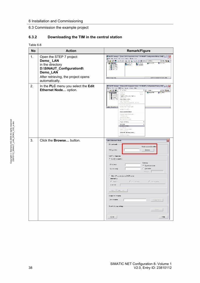
1. Open the STEP 7 project Demo_ LAN in the directory D:\SINAUT_Configuration8\ Demo_LAN After retrieving, the project opens automatically.
2. In the PLC menu you select the Edit Ethernet Node… option.
3. Click the Browse… button.
6 Installation and Commissioning
6.3 Commission the example project
SIMATIC NET Configuration 8- Volume 1 V2.0, Entry ID: 23810112 39
Co
pyr
igh
t
Sie
me
ns
AG
20
09
All
righ
ts r
ese
rve
d
23
810
112
_SIN
AU
T_L
AN
_D
OK
U_
V2
0_e
.do
c
No Action Remark/Figure
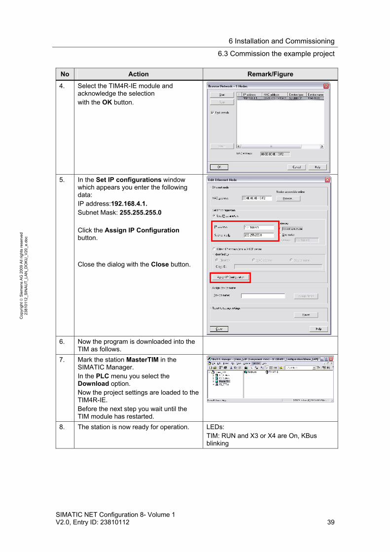
4. Select the TIM4R-IE module and acknowledge the selection with the OK button.
5. In the Set IP configurations window
which appears you enter the following data: IP address:192.168.4.1. Subnet Mask: 255.255.255.0 Click the Assign IP Configuration button. Close the dialog with the Close button.
6. Now the program is downloaded into the
TIM as follows.
7. Mark the station MasterTIM in the SIMATIC Manager. In the PLC menu you select the Download option. Now the project settings are loaded to the TIM4R-IE. Before the next step you wait until the TIM module has restarted.
8. The station is now ready for operation. LEDs: TIM: RUN and X3 or X4 are On, KBus blinking
6 Installation and Commissioning
6.3 Commission the example project
40 SIMATIC NET Configuration 8- Volume 1
V2.0, Entry ID: 23810112
Co
pyr
igh
t
Sie
me
ns
AG
20
09
All
righ
ts r
ese
rve
d
23
810
112
_SIN
AU
T_L
AN
_D
OK
U_
V2
0_e
.do
c
6.3.3 Download station 2 and 3
Table 6-9
No Action Remark/Figure
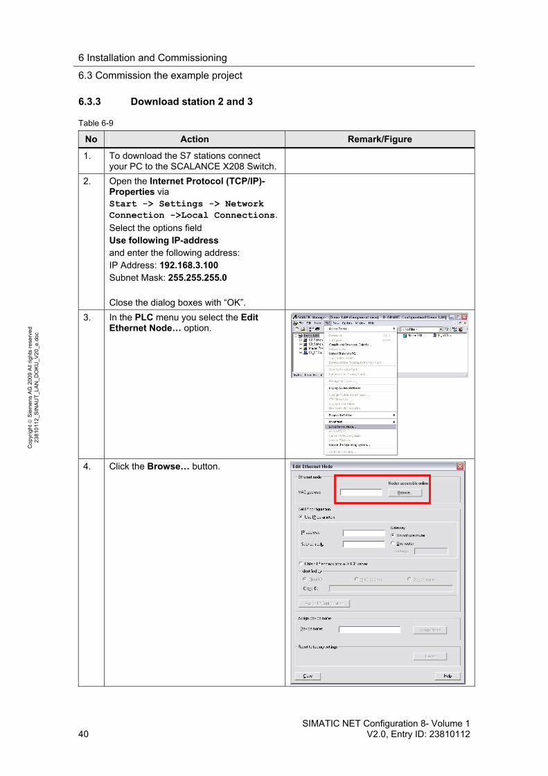
1. To download the S7 stations connect your PC to the SCALANCE X208 Switch.
2. Open the Internet Protocol (TCP/IP)-Properties via Start -> Settings -> Network Connection ->Local Connections.
Select the options field Use following IP-address and enter the following address: IP Address: 192.168.3.100 Subnet Mask: 255.255.255.0 Close the dialog boxes with “OK”.
3. In the PLC menu you select the Edit Ethernet Node… option.
4. Click the Browse… button.

6 Installation and Commissioning
6.3 Commission the example project
SIMATIC NET Configuration 8- Volume 1 V2.0, Entry ID: 23810112 41
Co
pyr
igh
t
Sie
me
ns
AG
20
09
All
righ
ts r
ese
rve
d
23
810
112
_SIN
AU
T_L
AN
_D
OK
U_
V2
0_e
.do
c
No Action Remark/Figure
5. The two TIM 3V-IE are displayed. Using the displayed MAC address and the MAC address displaced on the TIM module you first select TIM 3V-IE in Station 2. Confirm the selection with the OK button.
6. In the Set IP configurations window
which appears you enter the following data: IP Address:192.168.0.30 Subnet Mask: 255.255.255.0 Click the Assign IP Configuration button. Close the dialog with the Close button.
7. Mark the station 02_Station in the SIMATIC Manager. In the PLC menu you select the Download option. Now the project settings are loaded to the CPU 313 and the TIM 3V-IE. Before the next step you wait until the TIM module and the CPU has restarted.
8. The station is now ready for operation. LEDs: CPU: is in RUN DO 0.1: flashing slowly TIM: RUN and LINK are ON, KBus flashing
9. Repeat steps 3-8 for Station 3. Use the assigned IP address 192.168.3.30. To download station 3 mark station 03_Station in step 7.
6 Installation and Commissioning
6.3 Commission the example project
42 SIMATIC NET Configuration 8- Volume 1
V2.0, Entry ID: 23810112
Co
pyr
igh
t
Sie
me
ns
AG
20
09
All
righ
ts r
ese
rve
d
23
810
112
_SIN
AU
T_L
AN
_D
OK
U_
V2
0_e
.do
c
No Action Remark/Figure
10. Reconnect the PC to the TIM4R-IE and set the IP address of the PC as in table 6-5.
6.3.4 Activating the ST7cc and starting ST7cc & WinCC Runtime
Assign computer name
Table 6-10
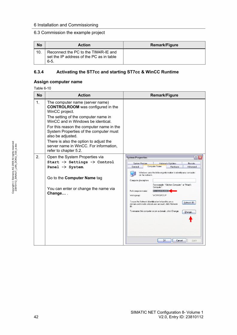
No Action Remark/Figure
1. The computer name (server name) CONTROLROOM was configured in the WinCC project. The setting of the computer name in WinCC and in Windows be identical. For this reason the computer name in the System Properties of the computer must also be adjusted. There is also the option to adjust the server name in WinCC. For information, refer to chapter 5.2.
2. Open the System Properties via Start -> Settings -> Control Panel -> System.
Go to the Computer Name tag You can enter or change the name via Change… .
6 Installation and Commissioning
6.3 Commission the example project
SIMATIC NET Configuration 8- Volume 1 V2.0, Entry ID: 23810112 43
Co
pyr
igh
t
Sie
me
ns
AG
20
09
All
righ
ts r
ese
rve
d
23
810
112
_SIN
AU
T_L
AN
_D
OK
U_
V2
0_e
.do
c
Open WinCC project and ST7cc Config settings
Table 6-11
No Action Remark/Figure
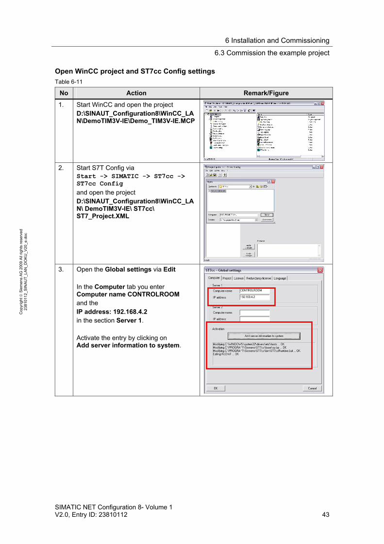
1. Start WinCC and open the project D:\SINAUT_Configuration8\WinCC_LAN\DemoTIM3V-IE\Demo_TIM3V-IE.MCP
2. Start S7T Config via
Start -> SIMATIC -> ST7cc -> ST7cc Config
and open the project D:\SINAUT_Configuration8\WinCC_LAN\ DemoTIM3V-IE\ ST7cc\ ST7_Project.XML
3. Open the Global settings via Edit
In the Computer tab you enter Computer name CONTROLROOM and the IP address: 192.168.4.2 in the section Server 1. Activate the entry by clicking on Add server information to system.

6 Installation and Commissioning
6.3 Commission the example project
44 SIMATIC NET Configuration 8- Volume 1
V2.0, Entry ID: 23810112
Co
pyr
igh
t
Sie
me
ns
AG
20
09
All
righ
ts r
ese
rve
d
23
810
112
_SIN
AU
T_L
AN
_D
OK
U_
V2
0_e
.do
c
No Action Remark/Figure
4. In the Project tab you press the button Activate current project for ST7cc Runtime. Press OK to quit the dialog. Save the settings now or when exiting ST7cc Config at the latest.
Start WinCC runtime and ST7cc
Table 6-12
No Action Remark/Figure
1. Start the ST7cc Runtime Start -> SIMATIC -> ST7cc -> ST7cc Runtime
2. The DOS output window opens and displays information on which programs are successively started by ST7cc
3. The Log window of the SINAUT server opens. It also shows the connection with the SINAUT stations and that the general queries for these stations, which are automatically started during system start, were terminated without error.
4. Wait until the ST7CC server is running. If this is the case the right hand window will appear.
6 Installation and Commissioning
6.3 Commission the example project
SIMATIC NET Configuration 8- Volume 1 V2.0, Entry ID: 23810112 45
Co
pyr
igh
t
Sie
me
ns
AG
20
09
All
righ
ts r
ese
rve
d
23
810
112
_SIN
AU
T_L
AN
_D
OK
U_
V2
0_e
.do
c
No Action Remark/Figure
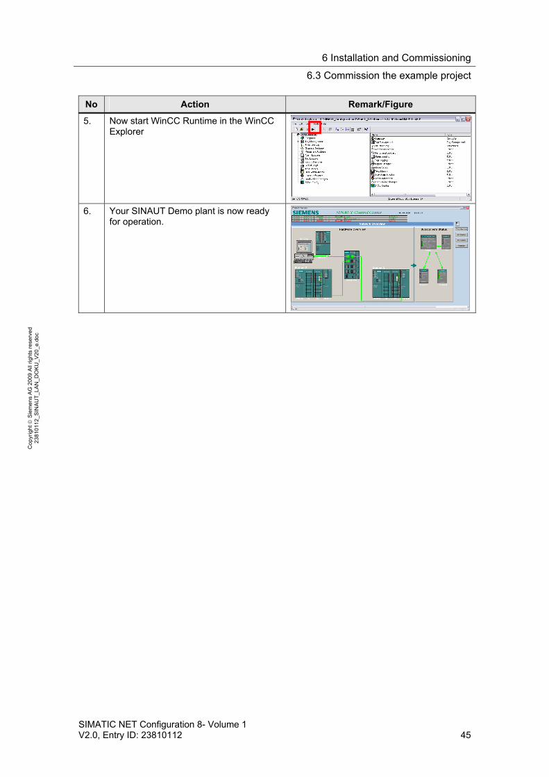
5. Now start WinCC Runtime in the WinCC Explorer
6. Your SINAUT Demo plant is now ready for operation.
7 Operation of the Application
7.1 Operating the SINAUT ST7cc project
46 SIMATIC NET Configuration 8- Volume 1
V2.0, Entry ID: 23810112
Co
pyr
igh
t
Sie
me
ns
AG
20
09
All
righ
ts r
ese
rve
d
23
810
112
_SIN
AU
T_L
AN
_D
OK
U_
V2
0_e
.do
c
7 Operation of the Application
Introduction
In the following chapters we will introduce the operation of the demo-project as well as the test and diagnostic functions provided by the used components:
7.1 Operating the SINAUT ST7cc project
Table 7-1
No Action Remark/Figure
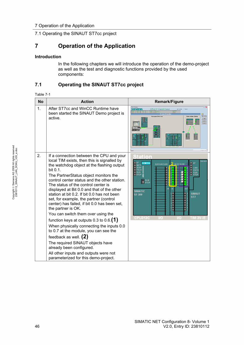
1. After ST7cc and WinCC Runtime have been started the SINAUT Demo project is active.
2. If a connection between the CPU and your local TIM exists, then this is signalled by the watchdog object at the flashing output bit 0.1. The PartnerStatus object monitors the control center status and the other station. The status of the control center is displayed at Bit 0.0 and that of the other station at bit 0.2. If bit 0.0 has not been set, for example, the partner (control center) has failed, if bit 0.0 has been set, the partner is OK. You can switch them over using the
function keys at outputs 0.3 to 0.6.(1)
When physically connecting the inputs 0.0 to 0.7 at the module, you can see the
feedback as well. (2)
The required SINAUT objects have already been configured. All other inputs and outputs were not parameterized for this demo-project.
7 Operation of the Application
7.2 Subscribers Status
SIMATIC NET Configuration 8- Volume 1 V2.0, Entry ID: 23810112 47
Co
pyr
igh
t
Sie
me
ns
AG
20
09
All
righ
ts r
ese
rve
d
23
810
112
_SIN
AU
T_L
AN
_D
OK
U_
V2
0_e
.do
c
7.2 Subscribers Status
Table 7-2
No Action Remark/Figure
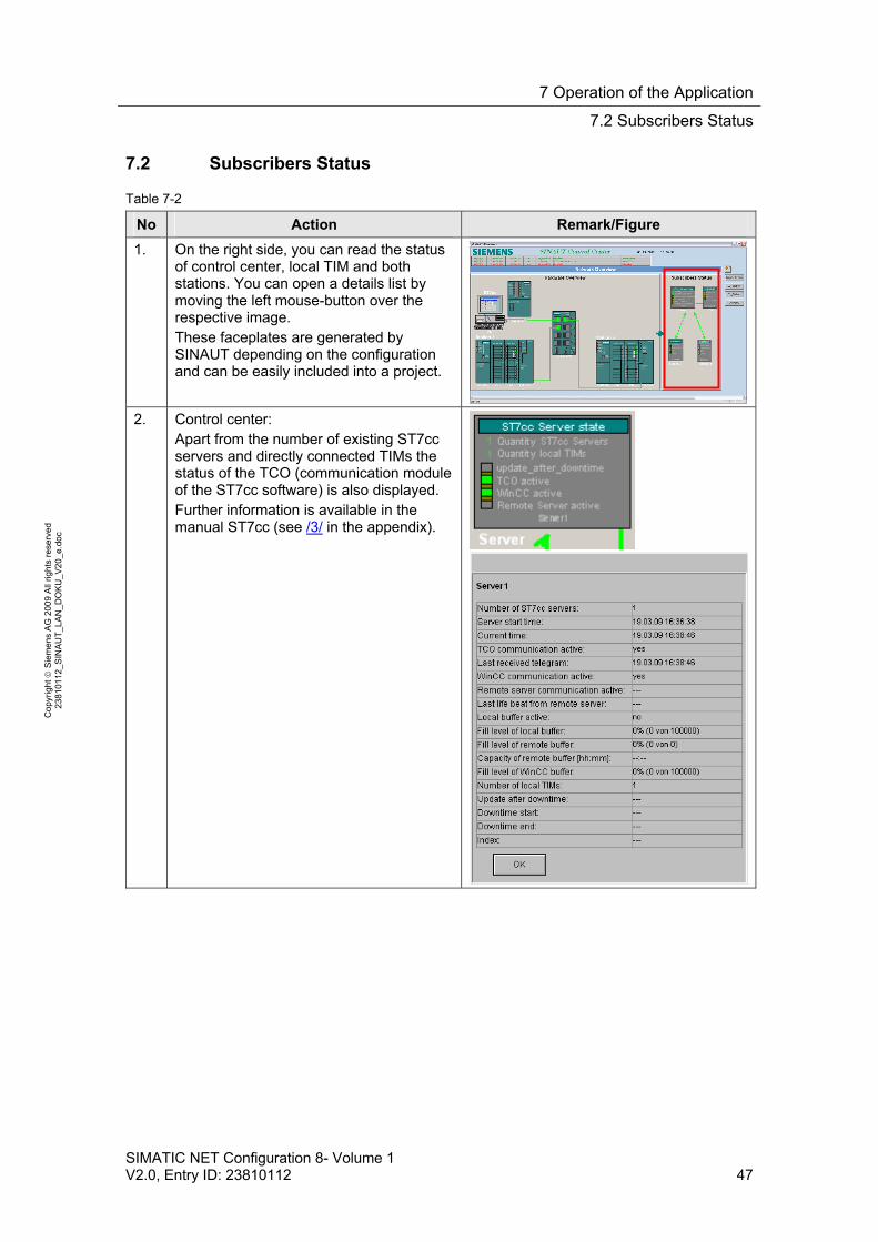
1. On the right side, you can read the status of control center, local TIM and both stations. You can open a details list by moving the left mouse-button over the respective image. These faceplates are generated by SINAUT depending on the configuration and can be easily included into a project.
2. Control center: Apart from the number of existing ST7cc servers and directly connected TIMs the status of the TCO (communication module of the ST7cc software) is also displayed. Further information is available in the manual ST7cc (see /3/ in the appendix).
7 Operation of the Application
7.2 Subscribers Status
48 SIMATIC NET Configuration 8- Volume 1
V2.0, Entry ID: 23810112
Co
pyr
igh
t
Sie
me
ns
AG
20
09
All
righ
ts r
ese
rve
d
23
810
112
_SIN
AU
T_L
AN
_D
OK
U_
V2
0_e
.do
c
No Action Remark/Figure
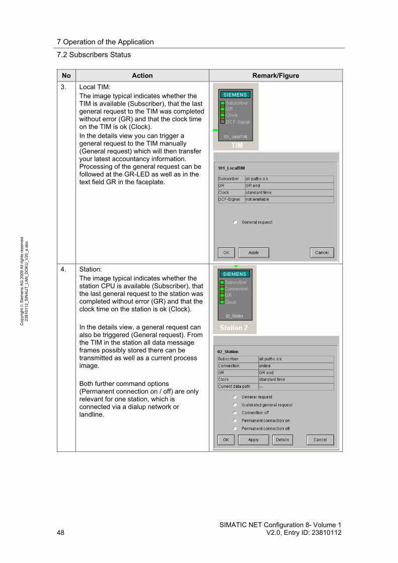
3. Local TIM: The image typical indicates whether the TIM is available (Subscriber), that the last general request to the TIM was completed without error (GR) and that the clock time on the TIM is ok (Clock). In the details view you can trigger a general request to the TIM manually (General request) which will then transfer your latest accountancy information. Processing of the general request can be followed at the GR-LED as well as in the text field GR in the faceplate.
4. Station: The image typical indicates whether the station CPU is available (Subscriber), that the last general request to the station was completed without error (GR) and that the clock time on the station is ok (Clock). In the details view, a general request can also be triggered (General request). From the TIM in the station all data message frames possibly stored there can be transmitted as well as a current process image. Both further command options (Permanent connection on / off) are only relevant for one station, which is connected via a dialup network or landline.
7 Operation of the Application
7.3 Error message list
SIMATIC NET Configuration 8- Volume 1 V2.0, Entry ID: 23810112 49
Co
pyr
igh
t
Sie
me
ns
AG
20
09
All
righ
ts r
ese
rve
d
23
810
112
_SIN
AU
T_L
AN
_D
OK
U_
V2
0_e
.do
c
7.3 Error message list
Table 7-3
No Action Remark/Figure
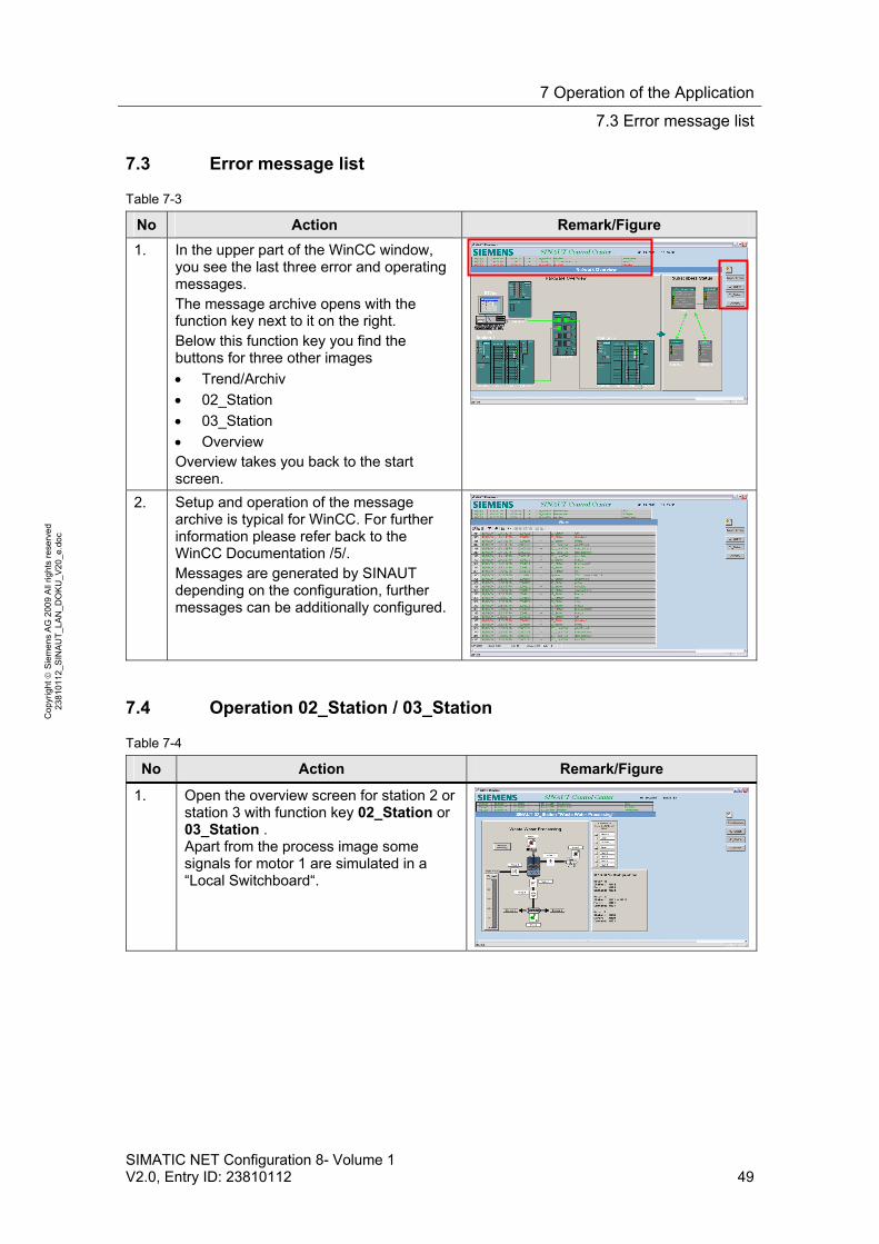
1. In the upper part of the WinCC window, you see the last three error and operating messages. The message archive opens with the function key next to it on the right. Below this function key you find the buttons for three other images
Trend/Archiv
02_Station
03_Station
Overview Overview takes you back to the start screen.
2. Setup and operation of the message archive is typical for WinCC. For further information please refer back to the WinCC Documentation /5/. Messages are generated by SINAUT depending on the configuration, further messages can be additionally configured.
7.4 Operation 02_Station / 03_Station
Table 7-4
No Action Remark/Figure
1. Open the overview screen for station 2 or station 3 with function key 02_Station or 03_Station . Apart from the process image some signals for motor 1 are simulated in a “Local Switchboard“.
7 Operation of the Application
7.4 Operation 02_Station / 03_Station
50 SIMATIC NET Configuration 8- Volume 1
V2.0, Entry ID: 23810112
Co
pyr
igh
t
Sie
me
ns
AG
20
09
All
righ
ts r
ese
rve
d
23
810
112
_SIN
AU
T_L
AN
_D
OK
U_
V2
0_e
.do
c
No Action Remark/Figure
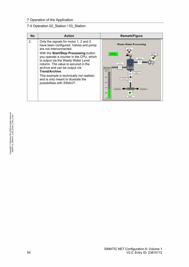
2. Only the signals for motor 1, 2 and 3 have been configured. Valves and pump are not interconnected. With the Start/Stop Processing button you operate a counter in the CPU, which is output via the Waste Water Level column. The value is secured in the archive and can be output via Trend/Archive. This example is technically not realistic and is only meant to illustrate the possibilities with SINAUT.
7 Operation of the Application
7.4 Operation 02_Station / 03_Station
SIMATIC NET Configuration 8- Volume 1 V2.0, Entry ID: 23810112 51
Co
pyr
igh
t
Sie
me
ns
AG
20
09
All
righ
ts r
ese
rve
d
23
810
112
_SIN
AU
T_L
AN
_D
OK
U_
V2
0_e
.do
c
No Action Remark/Figure
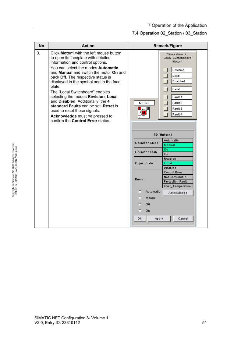
3. Click Motor1 with the left mouse button to open its faceplate with detailed information and control options. You can select the modes Automatic and Manual and switch the motor On and back Off. The respective status is displayed in the symbol and in the face plate. The “Local Switchboard” enables selecting the modes Revision, Local, and Disabled. Additionally, the 4 standard Faults can be set. Reset is used to reset these signals. Acknowledge must be pressed to confirm the Control Error status.
7 Operation of the Application
7.4 Operation 02_Station / 03_Station
52 SIMATIC NET Configuration 8- Volume 1
V2.0, Entry ID: 23810112
Co
pyr
igh
t
Sie
me
ns
AG
20
09
All
righ
ts r
ese
rve
d
23
810
112
_SIN
AU
T_L
AN
_D
OK
U_
V2
0_e
.do
c
No Action Remark/Figure
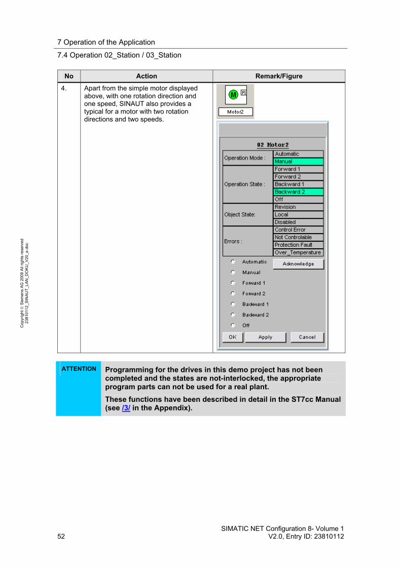
4. Apart from the simple motor displayed above, with one rotation direction and one speed, SINAUT also provides a typical for a motor with two rotation directions and two speeds.
ATTENTION Programming for the drives in this demo project has not been
completed and the states are not-interlocked, the appropriate program parts can not be used for a real plant.
These functions have been described in detail in the ST7cc Manual (see /3/ in the Appendix).
7 Operation of the Application
7.5 Archive
SIMATIC NET Configuration 8- Volume 1 V2.0, Entry ID: 23810112 53
Co
pyr
igh
t
Sie
me
ns
AG
20
09
All
righ
ts r
ese
rve
d
23
810
112
_SIN
AU
T_L
AN
_D
OK
U_
V2
0_e
.do
c
7.5 Archive
Table 7-5
No Action Remark/Figure
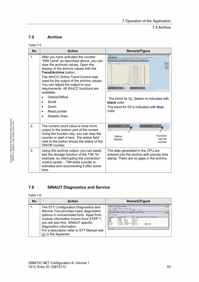
1. After you have activated the counter “WW Level“ as described above, you can view the archived values. Open the display of the archive values with the Trend/Archive button. The WinCC Online Trend Control was used for the output of the archive values. You can adjust the output to your requirements. All WinCC functions are available:
Online/Offline
Scroll
Zoom
Read pointer
Statistic Area
The trend for 02_Station is indicated with black color. The trend for 03 is indicated with blue color.
2. The current count value is once more output in the bottom part of the screen. Using the function key, you can stop the counter or start it here. The status field next to the button shows the status of the ON/Off counter.
3. Using this archive output, you can easily test the storage function of the TIM, for example, by interrupting the connection control center – TIM while counter is activated and reconnecting it after some time.
The data generated in the CPU are entered into the archive with precise time stamp. There are no gaps in the archive.
7.6 SINAUT Diagnostics and Service
Table 7-6
No Action Remark/Figure
1. The ST7 Configuration Diagnostics and Service Tool provides many diagnostics options in concentrated form. Apart from module information known from STEP 7, you will also find SINAUT specific diagnostics information. For a description refer to ST7 Manual see /2/ in the Appendix.
Function key for
counter
Status Display
7 Operation of the Application
7.7 Terminate WinCC and ST7cc Runtime
54 SIMATIC NET Configuration 8- Volume 1
V2.0, Entry ID: 23810112
Co
pyr
igh
t
Sie
me
ns
AG
20
09
All
righ
ts r
ese
rve
d
23
810
112
_SIN
AU
T_L
AN
_D
OK
U_
V2
0_e
.do
c
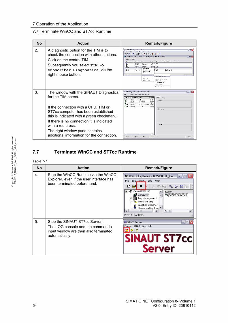
No Action Remark/Figure
2. A diagnostic option for the TIM is to check the connection with other stations. Click on the central TIM. Subsequently you select TIM –> Subscriber Diagnostics via the right mouse button.
3. The window with the SINAUT Diagnostics for the TIM opens. If the connection with a CPU, TIM or ST7cc computer has been established this is indicated with a green checkmark. If there is no connection it is indicated with a red cross. The right window pane contains additional information for the connection.
7.7 Terminate WinCC and ST7cc Runtime
Table 7-7
No Action Remark/Figure
4. Stop the WinCC Runtime via the WinCC Explorer, even if the user interface has been terminated beforehand.
5. Stop the SINAUT ST7cc Server. The LOG console and the commando input window are then also terminated automatically.
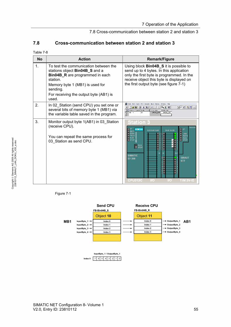
7 Operation of the Application
7.8 Cross-communication between station 2 and station 3
SIMATIC NET Configuration 8- Volume 1 V2.0, Entry ID: 23810112 55
Co
pyr
igh
t
Sie
me
ns
AG
20
09
All
righ
ts r
ese
rve
d
23
810
112
_SIN
AU
T_L
AN
_D
OK
U_
V2
0_e
.do
c
7.8 Cross-communication between station 2 and station 3
Table 7-8
No Action Remark/Figure
1. To test the communication between the stations object Bin04B_S and a Bin04B_R are programmed in each station. Memory byte 1 (MB1) is used for sending. For receiving the output byte (AB1) is used.
Using block Bin04B_S it is possible to send up to 4 bytes. In this application only the first byte is programmed. In the receive object this byte is displayed on the first output byte (see figure 7-1)
2. In 02_Station (send CPU) you set one or several bits of memory byte 1 (MB1) via the variable table saved in the program.
3. Monitor output byte 1(AB1) in 03_Station (receive CPU). You can repeat the same process for 03_Station as send CPU.
Figure 7-1
Index 0
Index 1
Index 2
Index 3
InputByte_1
InputByte_2
InputByte_3
InputByte_4
FB-Bin04B_S
.0.1.2.3.4.5.6.7
InputByte_1 / OutputByte_1
Index 0
OutputByte_1
OutputByte_2
OutputByte_3
OutputByte_4
FB-Bin04B_R
Index 0
Index 1
Index 2
Index 3
Object 10 Object 11
MB1 AB1
Send CPU Receive CPU
8 Glossary
56 SIMATIC NET Configuration 8- Volume 1
V2.0, Entry ID: 23810112
Co
pyr
igh
t
Sie
me
ns
AG
20
09
All
righ
ts r
ese
rve
d
23
810
112
_SIN
AU
T_L
AN
_D
OK
U_
V2
0_e
.do
c
Appendix and List of Further Literature
8 Glossary
DSL
Digital Subscriber Line, digital node connection line; households and company can send and received data with high transmission rate. DSL uses the already installed two to four copper lines of the telephone network, the "node connection line".
GPRS
General Packet Radio Service, general package oriented radio service. An expansion of the GSM mobile radio standard by package-oriented data transmission.
GSM
Global System for Mobile Communications is a fully digital mobile radio network standard.
LAN, WAN
LAN : Local Area Network Such a network has only one restricted geographical reach. As opposed to public networks, it is under the legal control of the user and restricted to an office building or company premises.
WAN: Wide Area Network, Wide area networks have been designed for language or data transmission over long distances. The concepts of such networks is mainly shaped by the service provider’s offers.
SINAUT ST7, ST7cc
SINAUT® ST7 is a SIMATIC® S7-based system for fully automatic monitoring and control of process stations, which exchange data with one or several control centers via WAN (Wide Area Network) or Ethernet (TCP/IP). SINAUT ST7cc (the PC control center) server as a control center, based on WinCC. It is a control center system particularly designed for the event controlled and time-stamped data transmission of the SINAUT system. The SINAUT software in the stations provides for a change-controlled process data transmission with the control center as well as between the individual CPUs. A particular feature of the TIM data transmission module, which is used in the SINAUT ST7 system, is the local storage of the data messages (including time stamp) during failure of the communication path, failure of a partner or for cost optimization for dialup networks.
TIM
Telecontrol Interface Module
9 Bibliography
SIMATIC NET Configuration 8- Volume 1 V2.0, Entry ID: 23810112 57
Co
pyr
igh
t
Sie
me
ns
AG
20
09
All
righ
ts r
ese
rve
d
23
810
112
_SIN
AU
T_L
AN
_D
OK
U_
V2
0_e
.do
c
The core piece of the SINAUT Telecontrol Hardware is the communication module TIM (Telecontrol Interface Module). It manages data traffic via the WAN. Using the TIM 3V-IE(Advanced), a SIMATIC S7-300 or a C7 complete device can exchange data with other SINAUT ST7 or ST1 partners via any SINAUT WAN network. Furthermore, this module extends the SINAUT communication to the Ethernet, i.e. to TCP/IP based networks. The most important SINAUT property, data storage including time stamp on the TIM at connection failure or failure of the partner, is hereby also provided for Ethernet connections. Important events, alarms etc. are not lost, and archives in the control center system are always filled continuously. SINAUT TD7 software so far available for the CPU (TD7onCPU) is integrated in the TIM 3V-IE (TD7onTIM). This enables using the smallest S7-CPUs 312 and 312C, as ideally no CPU main memory is required any longer for SINAUT.
The TIM4R-IE has the properties of the TIM3V-IE(Advanced). Additionally it can be connected with a S7-400 or with an ST7cc/ST7sc computer.
VPN tunnel
Virtual Private Network A computer network using a public network (e.g. the Internet) for transporting private data. Stations of VPN can exchange data like in an internal LAN. The connection via the public network is usually encoded. The term “tunnel“ refers to transmitting the data of a network protocol, embedded into a different network protocol.
WinCC
PC-based operating and monitoring system for visualizing and operating of processes, production processes, machines and plants in all branches with simple application up to distributed multi-terminal systems with redundant servers and location independent solutions with web clients. WinCC is the information pool for company wide, vertical integration.
9 Bibliography
9.1 Bibliographic References
This list is by no means complete and only provides a selection of appropriate sources.
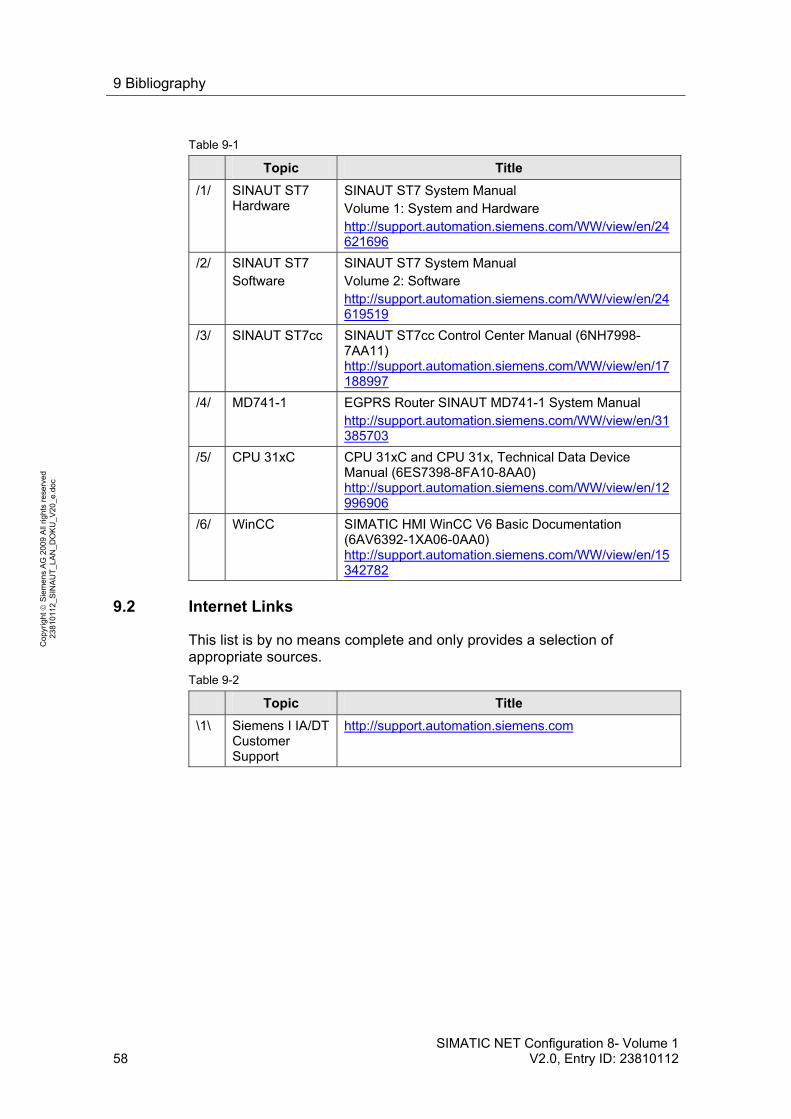
9 Bibliography
58 SIMATIC NET Configuration 8- Volume 1
V2.0, Entry ID: 23810112
Co
pyr
igh
t
Sie
me
ns
AG
20
09
All
righ
ts r
ese
rve
d
23
810
112
_SIN
AU
T_L
AN
_D
OK
U_
V2
0_e
.do
c
Table 9-1
Topic Title
/1/ SINAUT ST7 Hardware
SINAUT ST7 System Manual Volume 1: System and Hardware http://support.automation.siemens.com/WW/view/en/24621696
/2/ SINAUT ST7 Software
SINAUT ST7 System Manual Volume 2: Software http://support.automation.siemens.com/WW/view/en/24619519
/3/ SINAUT ST7cc SINAUT ST7cc Control Center Manual (6NH7998-7AA11) http://support.automation.siemens.com/WW/view/en/17188997
/4/ MD741-1 EGPRS Router SINAUT MD741-1 System Manual http://support.automation.siemens.com/WW/view/en/31385703
/5/ CPU 31xC CPU 31xC and CPU 31x, Technical Data Device Manual (6ES7398-8FA10-8AA0) http://support.automation.siemens.com/WW/view/en/12996906
/6/ WinCC SIMATIC HMI WinCC V6 Basic Documentation (6AV6392-1XA06-0AA0) http://support.automation.siemens.com/WW/view/en/15342782
9.2 Internet Links
This list is by no means complete and only provides a selection of appropriate sources.
Table 9-2
Topic Title
\1\ Siemens I IA/DT Customer Support
http://support.automation.siemens.com
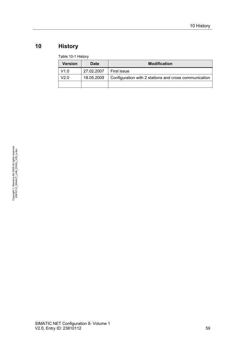
10 History
SIMATIC NET Configuration 8- Volume 1 V2.0, Entry ID: 23810112 59
Co
pyr
igh
t
Sie
me
ns
AG
20
09
All
righ
ts r
ese
rve
d
23
810
112
_SIN
AU
T_L
AN
_D
OK
U_
V2
0_e
.do
c
10 History
Table 10-1 History
Version Date Modification
V1.0 27.02.2007 First issue
V2.0 18.05.2009 Configuration with 2 stations and cross communication