3 compression mem
TRANSCRIPT

8/13/2019 3 Compression Mem
http://slidepdf.com/reader/full/3-compression-mem 1/17
Chapter 2: Member Design
Section 2 : Compression Members
27/9/00
.2
Failure modes
• Local buckling
• Overall yielding
• Overall buckling
8/13/2019 3 Compression Mem
http://slidepdf.com/reader/full/3-compression-mem 2/17
27/9/00
.3
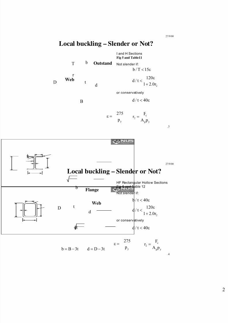
Local buckling – Slender or Not?
I and H Sections
Fig 5 and Table11
b
B
D td
T
r
Outstand
Web
y p275=ε
ε< 15T/ b
2r 0.21
120t/d
+
ε<
or conservatively
ε< 40t/d
yg
c2
pA
Fr =
Not slender if:
27/9/00
.4
Local buckling – Slender or Not?
b
Dd
B
tWeb
Flange
HF Rectangular Hollow Sections
Fig 5 and Table 12
y p
275=ε
ε< 40t/ b
2r 0.21
120t/d
+
ε<
or conservatively
ε< 40t/d
yg
c2
pA
Fr =
Not slender if:
t3B b −= t3Dd −=

8/13/2019 3 Compression Mem
http://slidepdf.com/reader/full/3-compression-mem 3/17
27/9/00
.5
Overall yielding
Satisfied by overall buckling check
Pc = ρy Ag
Pc =ρ
cA
g
27/9/00
.6
Elastic Buckling of Columns
2
2
EI
L
π
Euler Buckling Load
Pcr =L
2
cr 2
EA p
(L/r)
π=
Buckling stress
8/13/2019 3 Compression Mem
http://slidepdf.com/reader/full/3-compression-mem 4/17
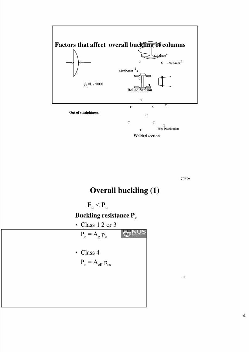
= L / 1000
Out of straightness
δ
+260 N/mm
-125 N/mm
+55 N/mm
Rolled Section
C
T
C C
C C
T
2
2
2
CC
T
CC
T
C
T
TWeb Distribution
Welded section
Factors that affect overall buckling of columns
27/9/00
.8
Overall buckling (1)
Buckling resistance Pc
• Class 1 2 or 3
Pc
= Ag p
c
• Class 4
Pc
= Aeff
pcs
Fc < Pc
8/13/2019 3 Compression Mem
http://slidepdf.com/reader/full/3-compression-mem 5/17
27/9/00
.9
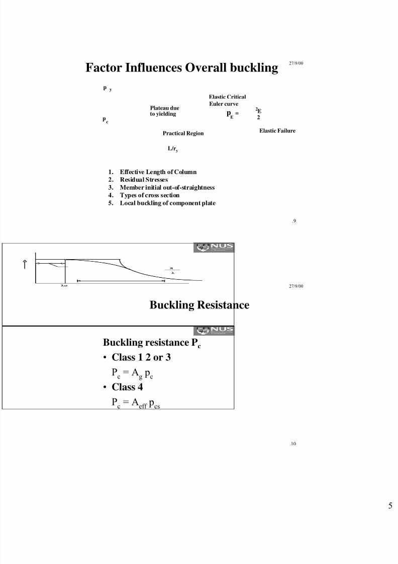
Factor Influences Overall buckling
Practical Region Elastic Failure
Elastic Critical
L/ry
p
Euler curve
p = E
2
2
E
Plateau dueto yielding
p y
c
1. Effective Length of Column
2. Residual Stresses
3. Member initial out-of-straightness
4. Types of cross section5. Local buckling of component plate
27/9/00
.10
Buckling Resistance
Buckling resistance Pc
• Class 1 2 or 3
Pc
= Ag p
c
• Class 4
Pc
= Aeff
pcs
8/13/2019 3 Compression Mem
http://slidepdf.com/reader/full/3-compression-mem 6/17
27/9/00
.11
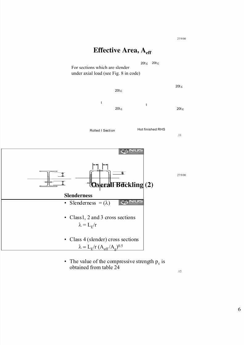
Effective Area, Aeff
tt
20tε
Rolled I Section Hot finished RHS
20t ε
20t ε
20t ε
20t ε
20t ε
For sections which are slender
under axial load (see Fig. 8 in code)
27/9/00
.12
Overall Buckling (2)
Slenderness
• Slenderness = (λ)
• Class1, 2 and 3 cross sections
λ = LE/r
• Class 4 (slender) cross sectionsλ = LE/r (Aeff /Ag)
0.5
• The value of the compressive strength pc isobtained from table 24

8/13/2019 3 Compression Mem
http://slidepdf.com/reader/full/3-compression-mem 7/17
27/9/00
.13
Strut Curves
• Four TABLES 24a, 24b, 24c, 24c
• Corresponding to 4 strut curves
27/9/00
.14
UK Strut Curves for S275 Steel
0204060
80100
200
260
280
10 30 50 70 90 110 130 150
pc
λUK a=2.0 UK a=3.5
UK a=5.5 UK a=8.0
HF SHS, I (x-x)
H (x-x), I (y-y), welded box,
Welded I and H about x-x
H (y-y),
welded H or I about (y-y)
Colded formed SHSThick sections
8/13/2019 3 Compression Mem
http://slidepdf.com/reader/full/3-compression-mem 8/17
27/9/00
.15
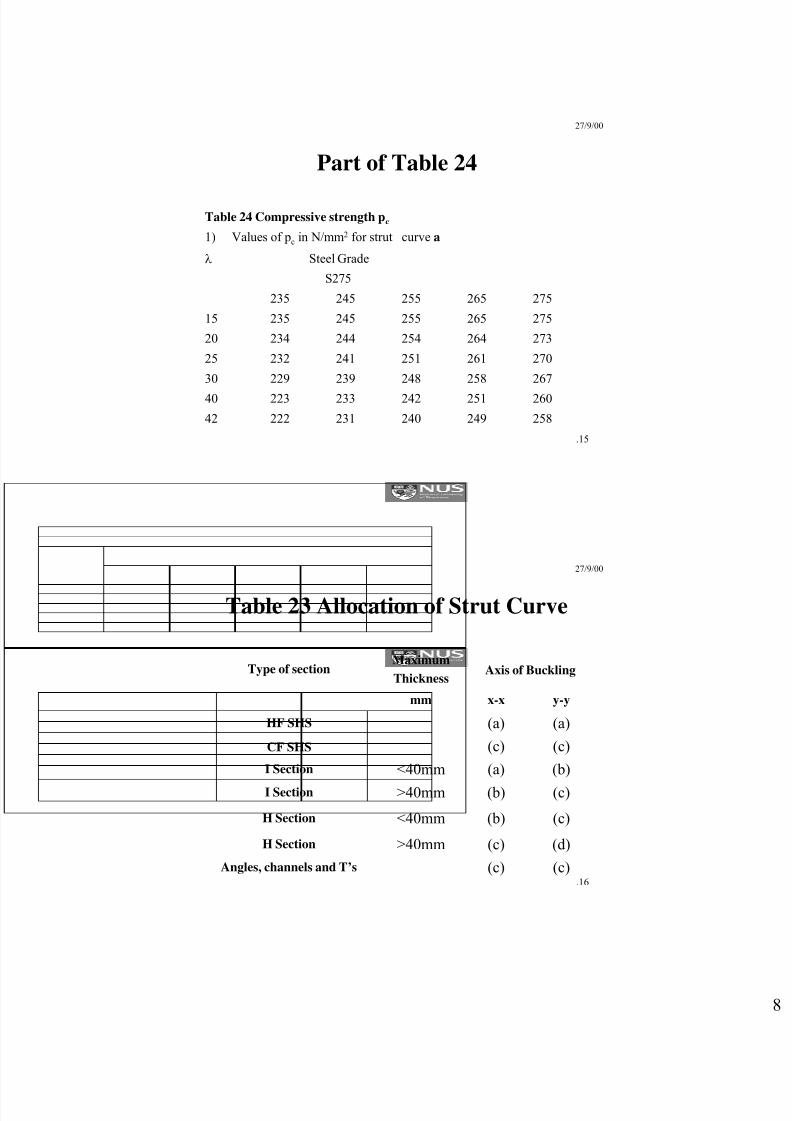
Part of Table 24
1) Values of pc in N/mm2 for strut curve a
25824924023122242
26025124223322340
26725824823922930
27026125124123225
27326425424423420
27526525524523515
275265255245235
S275
Steel Gradeλ
Table 24 Compressive strength pc
27/9/00
.16
Table 23 Allocation of Strut Curve
(d)(c)>40mmH Section
(c)(c)Angles, channels and T’s
(c)(b)<40mmH Section
(c)(b)>40mmI Section
(b)(a)<40mmI Section
(c)(c)CF SHS
(a)(a)HF SHS
y-yx-xmm
Axis of BucklingMaximum
ThicknessType of section
8/13/2019 3 Compression Mem
http://slidepdf.com/reader/full/3-compression-mem 9/17
27/9/00
.17
27/9/00
.18
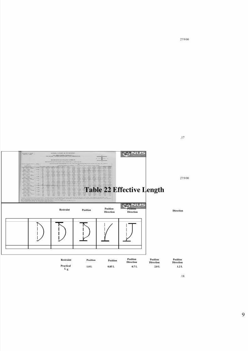
Table 22 Effective Length
PositionPosition Position
Position Position PositionPosition
Direction DirectionDirection
Direction Direction Direction
1.0 L 0.85 L 0.7 L 2.0 L 1.2 L
Position
Restraint
Restraint
PracticalL E
8/13/2019 3 Compression Mem
http://slidepdf.com/reader/full/3-compression-mem 10/17
27/9/00
.19
27/9/00
.20
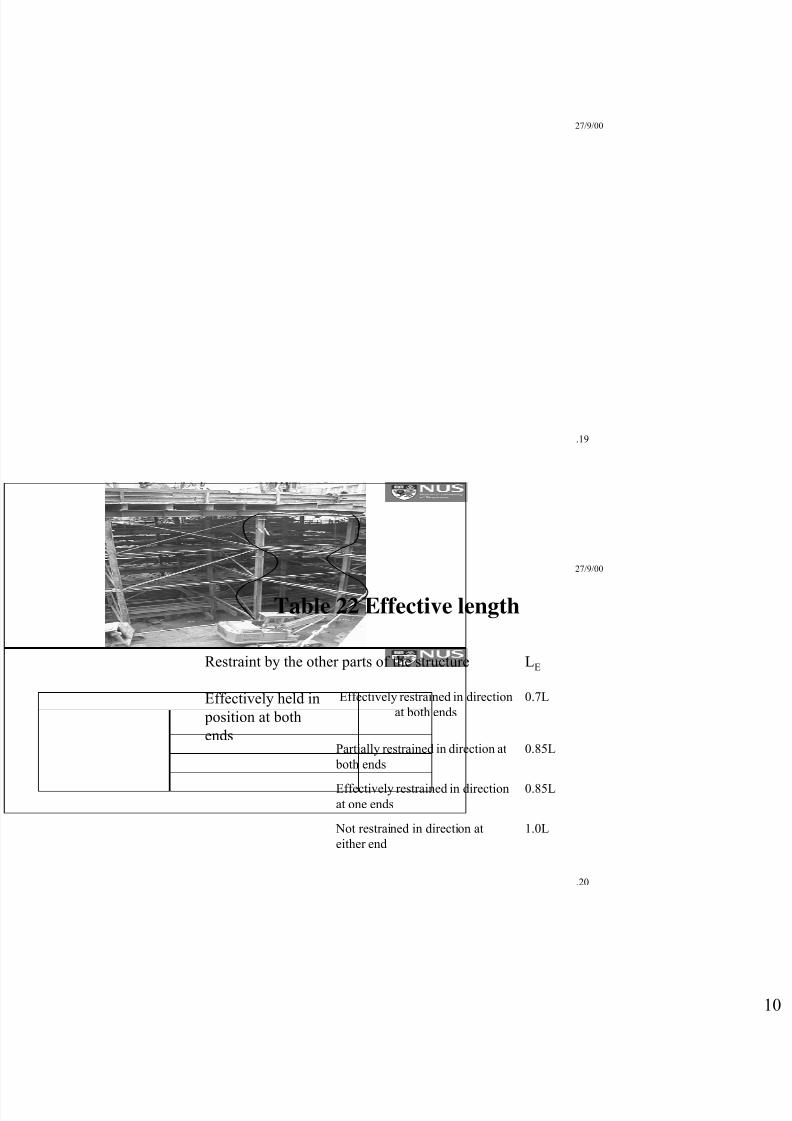
Table 22 Effective length
1.0L Not restrained in direction at
either end
0.85LEffectively restrained in directionat one ends
0.85LPartially restrained in direction at
both ends
0.7LEffectively restrained in direction
at both endsEffectively held in
position at both
ends
LERestraint by the other parts of the structure

8/13/2019 3 Compression Mem
http://slidepdf.com/reader/full/3-compression-mem 11/17
27/9/00
.21
Typical effective length
factor for use in
column design
=KL
K
L
27/9/00
.22
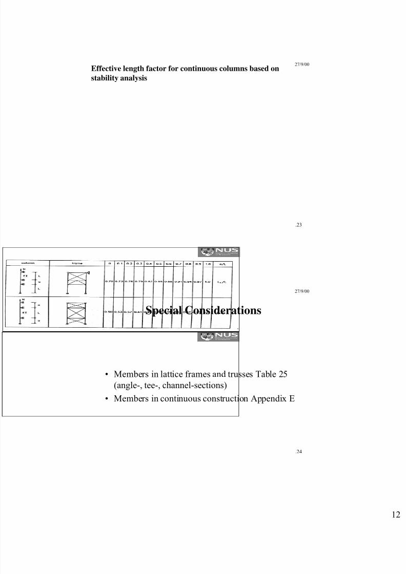
Effective length factor for continuous columns based on
stability analysis
8/13/2019 3 Compression Mem
http://slidepdf.com/reader/full/3-compression-mem 12/17
27/9/00
.23
Effective length factor for continuous columns based on
stability analysis
27/9/00
.24
Special Considerations
• Members in lattice frames and trusses Table 25
(angle-, tee-, channel-sections)
• Members in continuous construction Appendix E
8/13/2019 3 Compression Mem
http://slidepdf.com/reader/full/3-compression-mem 13/17
27/9/00
.25
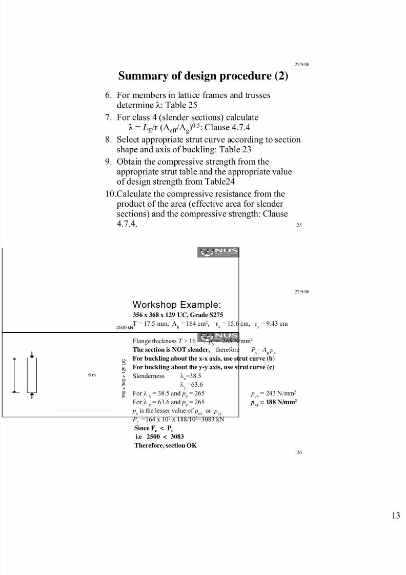
Summary of design procedure (2)
6. For members in lattice frames and trussesdetermine λ : Table 25
7. For class 4 (slender sections) calculateλ = LE/r (Aeff /Ag)
0.5: Clause 4.7.4
8. Select appropriate strut curve according to sectionshape and axis of buckling: Table 23
9. Obtain the compressive strength from theappropriate strut table and the appropriate valueof design strength from Table24
10.Calculate the compressive resistance from the
product of the area (effective area for slendersections) and the compressive strength: Clause4.7.4.
27/9/00
.26
Workshop Example:356 x 368 x 129 UC, Grade S275
T = 17.5 mm, Ag
= 164 cm2, r x
= 15.6 cm, r y
= 9.43 cm
Flange thickness T > 16 , py= 265 N/mm2
The section is NOT slender, therefore Pc= A
g p
c
For buckling about the x-x axis, use strut curve (b)
For buckling about the y-y axis, use strut curve (c)
Slenderness λx=38.5
λy= 63.6
For λx
= 38.5 and py
= 265 pcx
= 243 N/mm2
For λ y = 63.6 and py = 265 pcy = 188 N/mm2
pc
is the lesser value of pcx
or pcy
Pc
=164 x 102 x 188/103=3083 kN
Since Fc < Pc
i.e 2500 < 3083
Therefore, section OK
6 m
3 5 6 x 3 6 0 x 1 2 9 U C
2500 kN
8/13/2019 3 Compression Mem
http://slidepdf.com/reader/full/3-compression-mem 14/17
27/9/00
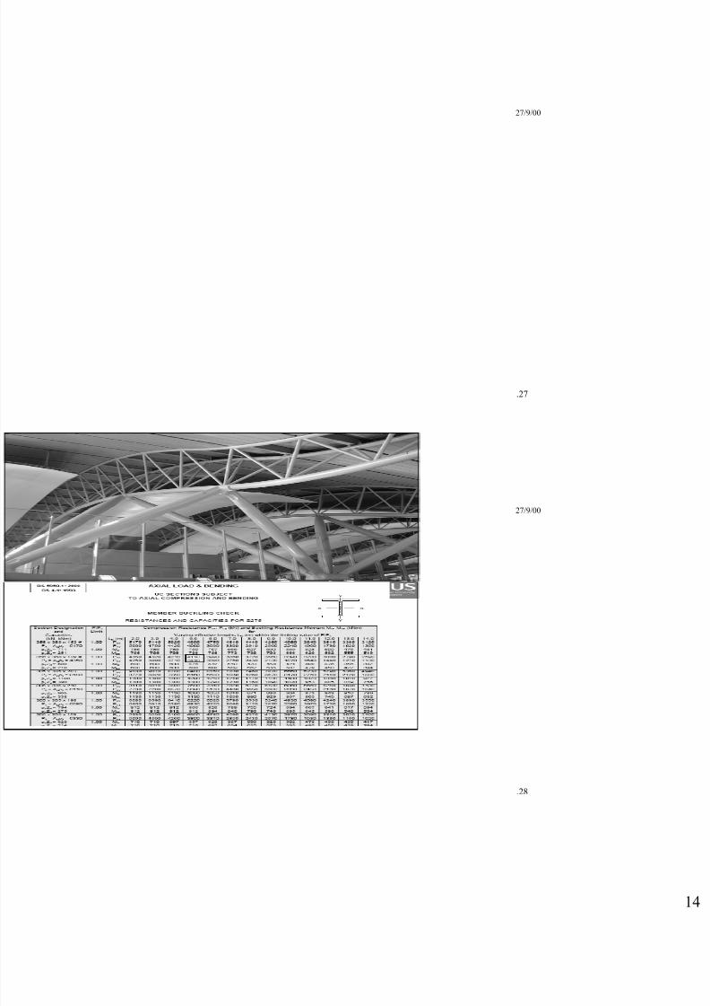
.27
27/9/00
.28
8/13/2019 3 Compression Mem
http://slidepdf.com/reader/full/3-compression-mem 15/17
27/9/00
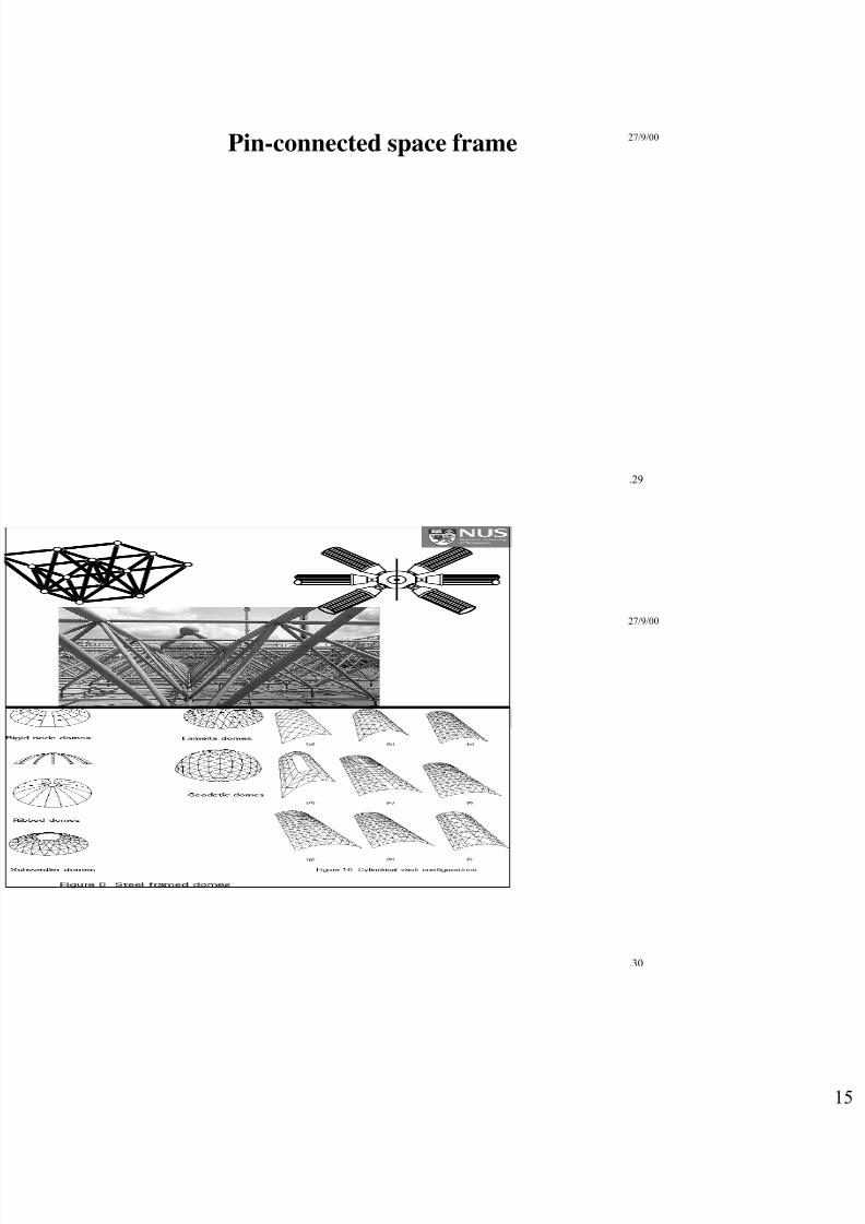
.29
Pin-connected space frame
27/9/00
.30

8/13/2019 3 Compression Mem
http://slidepdf.com/reader/full/3-compression-mem 16/17
27/9/00
.31
27/9/00
.32
8/13/2019 3 Compression Mem
http://slidepdf.com/reader/full/3-compression-mem 17/17
Reading assignmentsBS 5950:Part 1Code:
Clause 4.7
Reference : Chapter 2: Section 2