วย.321 การวิเคราะห์โครงสร้าง 1 ce321 structural...
TRANSCRIPT

วย.321 การวิเคราะหโ์ครงสรา้ง 1
CE321 Structural Analysis 1
นคร ภูว่โรดม
คณะวิศวกรรมศาสตร ์มหาวิทยาลยัธรรมศาสตร ์

Faculty of Engineering, Thammasat University CE321 Structural Analysis I
Prerequisite: CE 221 Objective: The objective of this course begins with an introduction to structural analysis for civil engineering students. The fundamental characteristics such as stresses or stress resultants, deflection and support reactions are studied. The analysis of structures involves determination of these quantities as cause by a given loading condition. This course presents the methods for analysis of structures with linear elastic behaviors in static equilibrium. Course outlines: 1. Introduction to structural analysis 2. Loads on structures 3. Equilibrium and support reactions 4. Plane and space trusses 5. Beams and frames: shear and bending moment 6. Deflections of beams: Geometric methods 7. Deflections of trusses, beams and frames: work-energy method 8. Influence lines 9. Analysis of statically indeterminate structures: method of consistent deformation
สัปดาห์ที ่ หัวข้อ/รายละเอยีด จํานวนช่ัวโมง 1 หลกัการเบ้ืองตน้ของการวิเคราะห์โครงสร้าง (1-3) 3
2-3 การวิเคราะห์แรงภายในโครงถกั (4) 6 4-6 แรงปฏิกิริยา แรงเฉือน และโมเมนตด์ดัในโครงสร้างดีเทอร์
มิเนทเชิงสถิต (5) 9
7 การวิเคราะห์โครงสร้างโดยวิธีทางเรขาคณิต (6) 3 8-10 การวิเคราะห์การเสียรูปของโครงสร้างดีเทอร์มิเนทเชิงสถิต
โดยวิธีงานเสมือนและพลงังานความเครียด (7) 9
11-12 เสน้อิทธิพลสาํหรับโครงสร้างดีเทอร์มิเนทเชิงสถิต (8) 6 13-15 การวิเคราะห์โครงสร้างอินดีเทอร์มิเนทเชิงสถิตโดยวิธีการ
เสียรูปท่ีคงตวั (9) 9

Lecturer: Nakhorn Poovarodom, Ph.D. Textbooks: 1. A. Kassimali, “Structural Analysis”, 2nd ed., PWS Publishing, 1999 2. R. C. Hibbeler, “Structural Analysis”, 4th ed., Prentice-Hall Inc., 1999 References:
1. ปณธิาน ลักคุณะประสทิธิ์, “การวิเคราะห์โครงสร้าง”, สมาคมวิศวกรรมสถานแห่งประเทศไทย, กรกฎาคม ๒๕๓๘
2. R. C. Coates, M. G. Coutie, F. K. Kong, “Structural Analysis”, 3rd ed., Chapman & Hall, 1988
3. C. K. Wang, “Intermediate Structural Analysis”, McGraw-Hill, 1983 Conducts of Course Lecture 3 hours/week. Grade will be based on (tentative) Mid-term examination I 20 % Test 10 % Mid-term examination II 30 % Final examination 30 % Homework/Quiz/Project 10 %
Contents Chapter 1: Introduction to Structural Analysis 1.1 Role of Structural Analysis in Structural Engineering Projects 1 1.2 Classification of Structures 1 1.3 Analytical Model 2 Chapter 2: Loads on Structures 2.1 Dead Loads 4 2.2 Live Loads 4 2.3 Impact 4 2.4 Environmental Loads 4 2.5 Hydrostatic and Soil Pressure 5 2.6 Thermal and other effects 5 2.7 Load Combinations 5 Chapter 3: Equilibrium and Support Reactions 3.1 Equilibrium of structure 6 3.2 External and Internal Forces 6 3.3 Types of Supports for Plane Structures 6 3.4 Static Determinacy, Indeterminacy and Instability (Plane Structure) 7 3.5 Principle of Superposition 10 Chapter 4: Plane and Space Trusses 4.1 Assumptions for analysis of trusses 11 4.2 Arrangement of members of plane trusses: Internal stability 12 4.3 Equation of condition for plane trusses 12 4.4 Static Determinacy, Indeterminacy and Instability (plane truss) 13 4.5 Analysis of Plane truss by the method of joints 13 4.6 Analysis of Plane Truss by the Method of Sections 14 4.7 Analysis of Compound truss 15 4.8 Complex truss 15 4.9 Space Trusses 15 Examples 18 Chapter 5: Beams and Frames: Shear and Bending Moment 5.1 Axial force, Shear and Bending moment 27 5.2 Shear Force Diagram (SFD) and Bending Moment Diagram (BMD) 27 5.3 Qualitative Deflected Shapes 27 5.4 Relationship between Loads, Shear and Bending Moments 28 5.5 Static Determinacy, Indeterminacy and Instability of Plan Frame 30 Examples 31
Chapter 6: Deflections of beams: Geometric methods 6.1 Differential equation for beam deflection 43 6.2 Direct integration method 44 6.3 Moment area method 45 6.4 Bending moment diagram by parts 46 Chapter 7: Deflections of trusses, beams and frames: Work-Energy method 7.1 Work 48 7.2 Principle of Virtual Work 49 7.3 Deflections of Trusses by the Virtual Work Method 51 7.4 Deflections of Beams by the Virtual Work Method 52 7.5 Deflections of Frames by the Virtual Work Method 54 7.6 Conservation of Energy and Strain Energy 55 7.7 Castigliano’s second Theorem 56 7.8 Betti’s Law and Maxwell’s Law of reciprocal deflections 59 Examples 60 Chapter 8: Influence Lines 8.1 Influence line for beams and frames by equilibrium method 84 8.2 Müller–Breslau’s principle and qualitative Influence Lines. 85 8.3 Influence line for Deflections 86 Examples 88 Chapter 9: Method of Consistent Deformation: Force Method 9.1 Introduction 95 9.2 Structure with a single degree of indeterminacy 95 9.3 Internal Forces and Moments as redundants 98 9.4 Structures with Multiple Degrees of Indeterminacy 100 9.5 Support settlements 101 9.6 Temperature change and Fabrication Errors 103 9.7 Method of Least Work 103 Examples 104 Appendix
Structural Analysis I
N. Poovarodom 1
Chapter 1 Introduction to Structural Analysis
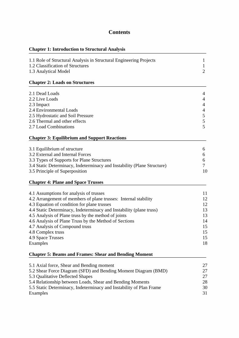
1.1 Role of Structural Analysis in Structural Engineering Projects a) Planning Phase: To establish the functional requirements of the proposed structure - Aesthetics - Environmental impact b) Preliminary Structural Design: To estimate sizes of members by approximate analysis, past experiences or code requirements c) Estimation of Loads: Dead load, live load, environmental loads, etc. d) Structural Analysis: Loads Structure Stresses, deflections, support reactions e) Safety and serviceability checks: by building code requirements if the design is not satisfied, repeat step b to e f) Construction phase: Drawing, specification construction 1.2 Classification of Structures a) Tension structure; cable (no bending stiffness, no compression)
b) Compression structure
Column Arch

Structural Analysis I
N. Poovarodom 2
c) Truss; members are in pure tension or compression, hinge joint d) Shear structure; for example, reinforced concrete shear wall e) Bending structure; beam, rigid frame, slab, plate 1.3 Analytical Model To simplify the analysis of a complicate structure Plane / Space Structure Plane Structure: all the members of structure and the applied loads lie in a single plane (2 Dimensions) Space structure: (3 Dimensions) Example Bridge

Structural Analysis I
N. Poovarodom 3
Building
Connections a) Rigid; all members have the same translation and rotation
Transmit force & moment b) Hinge; all members have the same translation Transmit only force
Supports a) Fixed support b) Hinged support c) Roller

Structural Analysis I
N. Poovarodom 4
Chapter 2 Loads on Structures
Types of Load Load estimation
Reference: ASCE 7 Standard
2.1 Dead Loads: Gravity load of constant magnitude and fixed position that act permanently on structure.
= weight of structure + equipments
Unit weight 3ft/lb 3m/kN 3m/kg - Concrete (RC) 150 23.6 2400 - Structural steel 490 77.0 7850 - Wood 40 6.3 640
2.2 Live Loads: load of varying magnitudes and/or positions caused by the use of the structure. LL for Building uniformly distributed surface load (load per unit area) LL for Bridge by “The American Association of state Highway and Transportation Officials” (AASHTO) Use the maximum effect of truck load (a) or lane load (b) 2.3 Impact: The dynamic effect of load
Impact factor 3.0125
50
LI
L = span length (ft) 2.4 Environmental Loads Example - Wind load - Earthquake load
W (hinge) (hi )

Structural Analysis I
N. Poovarodom 5
2.5 Hydrostatic and Soil Pressure
h = unit weight of media (liquid / soil) 2.6 Thermal and other effects - Temperature changes (elongation / shortening) - Fabrication errors - Support movements 2.7 Load Combinations The structure must be designed to have adequate strength to resist the most unfavorable of all the load combination * Serviceability requirement - Deflections - Vibrations - Cracking - Corrosion - Fatigue

Structural Analysis I
N. Poovarodom 6
Chapter 3 Equilibrium and Support Reactions
3.1 Equilibrium of structure
Plane 2D 0,0,0 zyx MFF
Space 3D 0,0,0 zyx FFF
and 0,0,0 zyx MMM
3.2 External and Internal Forces External Force = the actions of other bodies on the structure under consideration - Applied forces (load)
- Reactions Internal Force = the forces and couples exerted on a member or portion of the structure by the rest of the structure 3.3 Types of Supports for Plane Structures
x
y
z
x
y
Structural Analysis I
N. Poovarodom 7
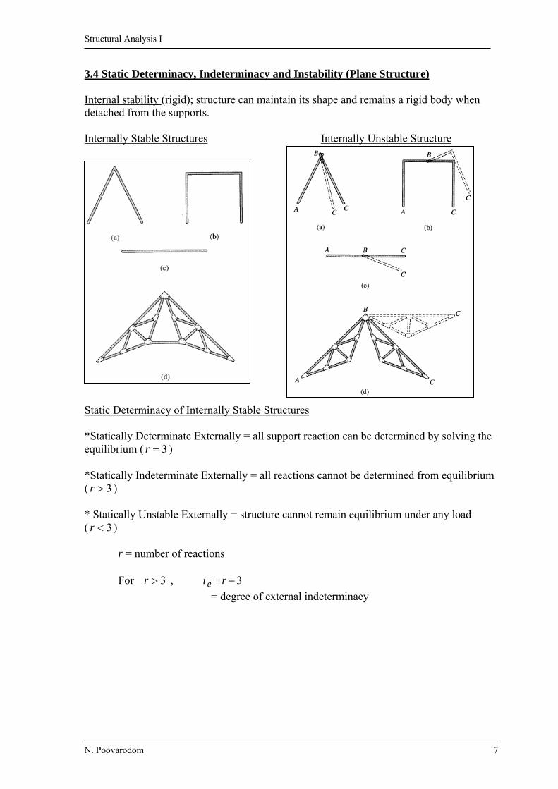
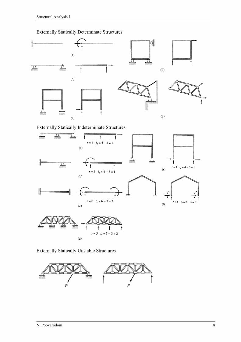
3.4 Static Determinacy, Indeterminacy and Instability (Plane Structure) Internal stability (rigid); structure can maintain its shape and remains a rigid body when detached from the supports. Internally Stable Structures Internally Unstable Structure Static Determinacy of Internally Stable Structures *Statically Determinate Externally = all support reaction can be determined by solving the equilibrium ( 3r ) *Statically Indeterminate Externally = all reactions cannot be determined from equilibrium ( 3r ) * Statically Unstable Externally = structure cannot remain equilibrium under any load ( 3r ) r = number of reactions For 3r , 3 ri e
= degree of external indeterminacy
Structural Analysis I
N. Poovarodom 8
Externally Statically Determinate Structures Externally Statically Indeterminate Structures Externally Statically Unstable Structures

Structural Analysis I
N. Poovarodom 9
Special case: geometrically unstable externally Static Determinacy of Internal Unstable Structures ( Equation of condition) Fig a) Internally unstable structure 3r , external unstable Fig b) 4r , stable (unknown = 4) Equation Equilibrium 3 + condition at B 1 Number of unknown = equation statically determinate externally Fig c) 5r
Equilibrium 3 5 Condition 0Fx at B 1
Condition 0M at B 1 statically determinate externally cer 3 = statically unstable externally ce = 1 for hinge
cer 3 = statically determinate externally = 2 for roller
cer 3 = statically indeterminate externally
“Degree of external indeterminacy” )3( ce eri
Structural Analysis I
N. Poovarodom 10
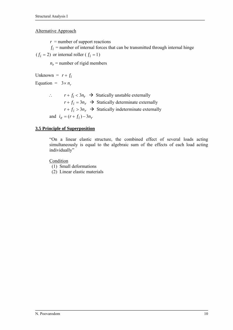
Alternative Approach r = number of support reactions
if = number of internal forces that can be transmitted through internal hinge
)2( if or internal roller ( 1if )
rn = number of rigid members Unknown = ifr
Equation = rn3 ri nfr 3 Statically unstable externally
ri nfr 3 Statically determinate externally
ri nfr 3 Statically indeterminate externally
and rie nfri 3)(
3.5 Principle of Superposition
“On a linear elastic structure, the combined effect of several loads acting simultaneously is equal to the algebraic sum of the effects of each load acting individually” Condition (1) Small deformations (2) Linear elastic materials
Structural Analysis I
N. Poovarodom 11
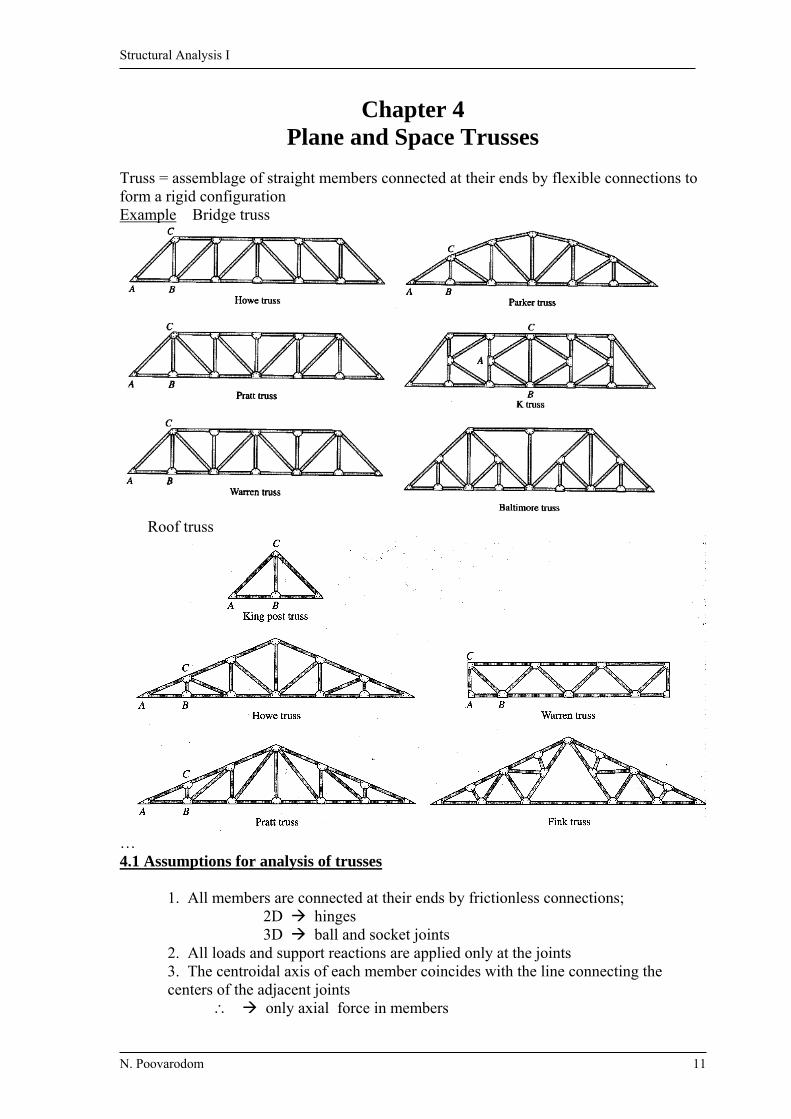
Chapter 4 Plane and Space Trusses
Truss = assemblage of straight members connected at their ends by flexible connections to form a rigid configuration Example Bridge truss Roof truss
… 4.1 Assumptions for analysis of trusses 1. All members are connected at their ends by frictionless connections; 2D hinges
3D ball and socket joints 2. All loads and support reactions are applied only at the joints 3. The centroidal axis of each member coincides with the line connecting the centers of the adjacent joints only axial force in members

Structural Analysis I
N. Poovarodom 12
4.2 Arrangement of members of plane trusses : Internal stability Internally stable = Truss does not change its shape when detached from supports
Basic Truss Element
3 members and 3 joint Simple Truss By enlarging basic truss element; adding two additional members for each additional joint m = total number of members j = total number of joints 32)3(23 jjm Compound Truss By connecting 2 or more simple trusses and each truss is connected to
others by connections capable of transmitting at least 3 force components.
Example Internal stability (Simple and compound truss) 32 jm Internally unstable 32 jm Internally stable (with proper arrangement of members) 4.3 Equation of condition for plane trusses

Structural Analysis I
N. Poovarodom 13
4.4 Static Determinacy, Indeterminacy and Instability (plane truss) Example Unknown Reaction 3 (r) Member force (axial only) 5 (m)
* force at joint = force in member (Newton rd3 law) Total unknown U = 3 + 5 = 8 Equation Equilibrium at joint; 1 joint 0,0 yx FF (j)
Total equation from j joint; E = 4 joint × 2 = 8 Equations 8E for 8U Statically Determinate for r = number of reactions m = number of members j = number of joints
1) jrm 2 Statically Unstable Truss
2) jrm 2 Statically Determinate Truss
3) jrm 2 Statically Indeterminate Truss Condition 1) is necessary and sufficient (true for all cases) Condition 2) and 3) are necessary but not sufficient (dependent of truss arrangement) Degree of static indeterminacy
jrmi 2)( 4.5 Analysis of Plane truss by the method of joints Determine the axial forces by considering the equilibrium of its joints
- Start from a joint with no more than 2 unknown forces or - Start from determining reactions by equilibrium of system

Structural Analysis I
N. Poovarodom 14
Identification of zero-force members 1) If only 2 non-collinear members are connected to a joint that has no external loads or reactions applied to it
2 members are zero-force member 2) If three members, two of which are collinear, are connected to a joint that has no external load or reaction applied to it
The non-collinear member is zero force member
Procedure for analysis 1) Check the truss for static determinacy 2) Identify any zero-force member 3) Determine the slope of the inclined members (except zero-force member) 4) Draw FBD of the whole truss 5) Select a joint that has no more than 2 unknown If no such joint, determine support reaction first, then select a joint 6) a: Draw FBD of the selected joint Tensile force: arrow pulling away the joint Compressive force: arrow pushing into the joint b: Determine unknown by 0 xF and 0 yF at the joint
7) Carry on the analysis for the remaining joints 4.6 Analysis of Plane Truss by the Method of Sections This method is efficient for determining only certain members of a truss “Cutting the truss into two portions, pass through the members whose forces are desired” In general, sections should not pass through more than 3 unknown forces Procedure for Analysis
1) Select a section that passes through unknown ( 3 unknown) 2) Select the portion that requires the least amount of computational effort in determining the unknown forces 3) Draw FBD of truss, determine unknowns by equilibrium equation

Structural Analysis I
N. Poovarodom 15
4.7 Analysis of Compound truss Using a combination of the method of joint and method of section can solve some problems of compound trusses 4.8 Complex truss Complex truss is not a simple truss and not a compound truss. It can not be solved by method of joint or method of section. Member forces can be determined by writing two equilibrium equations in terms of unknown member forces for each joint and then solving the system of 2j equations simultaneously. 4.9 Space Trusses Simple internally stable space truss
A simple space truss is formed by enlarging the tetrahedron element (Six members + four joints) by adding 3 members for one more joint The total number of members “m” for “j ” joint 63)4(36 jjm Reactions
Structural Analysis I
N. Poovarodom 16
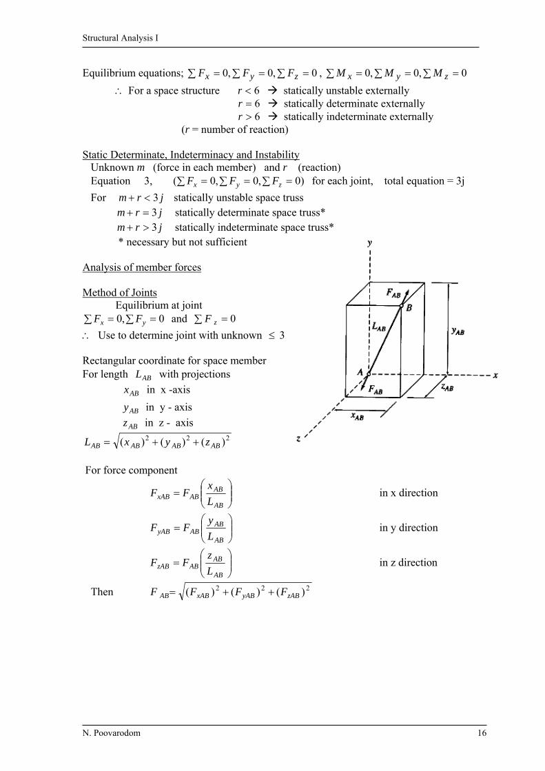
Equilibrium equations; 0,0,0 zyx FFF , 0,0,0 zyx MMM
For a space structure 6r statically unstable externally 6r statically determinate externally 6r statically indeterminate externally (r = number of reaction) Static Determinate, Indeterminacy and Instability Unknown m (force in each member) and r (reaction) Equation 3, )0,0,0( zyx FFF for each joint, total equation = 3j
For jrm 3 statically unstable space truss jrm 3 statically determinate space truss* jrm 3 statically indeterminate space truss*
* necessary but not sufficient Analysis of member forces Method of Joints Equilibrium at joint
0,0 yx FF and 0 zF
Use to determine joint with unknown 3 Rectangular coordinate for space member For length ABL with projections
ABx in x -axis
ABy in y - axis
ABz in z - axis 222 )()()( ABABABAB zyxL
For force component
AB
ABABxAB L
xFF in x direction
AB
ABAByAB L
yFF in y direction
AB
ABABzAB L
zFF in z direction
Then 222 )()()( zAByABxABAB FFFF

Structural Analysis I
N. Poovarodom 17
Zero force member
a) if only AEF is not in the same b) if ACF and ABF are not collinear,
plane AEF = 0 they are zero force member Method of Sections - Pass an imaginary section through the truss - Divide truss into portion that no more than 6 unknowns can be determined

Structural Analysis I
N. Poovarodom 18
Example 4.1: Determine force in all members of the truss shown.
m = 7 , r = 3 , j = 5, m + r = 2j (statically determinate) Determine reaction by 0, MF
Equilibrium at Joint C
60cos CEF ( 1.53 )
100CEF kN (T)
0sin CECB FF
80CBF kN
= 80 kN (C)
Joint E
0
cos10060cos
EB
EB
F
F
sin100EDF
80EDF kN (T)
Joint B 60cos BDF
100BDF kN 100 kN (C) 0sin10080 BAF
Joint A
100cos
60
ADF kN (T)
4m 4m 4m
3m
E D
C B A 60 kN
80 kN
60 kN 60 kN
60kN
80kN
4m
FCE
FCB
60
100
FED
FEB
60
80
60
FBD
FBA
80 0
60 FAD

Structural Analysis I
N. Poovarodom 19
Member force;
Example 4.2: Determine force in all members of the truss shown. m = 10 , r = 4 , j = 7 m+r=2j (determinate) Determine reaction
;0XF 10 XX BA
;0YF 60 YY BA
;0BM + 012610320620920 YA
kNAY 25 Condition equation ;0GM +
032066 YX AA
kNB
kNB
kNA
kNA
Y
X
Y
X
35
25
25
15
3m
3m
3m 3m 3m 3m
20 20
BY
Bx
AY
Ax
20kN
10kN20kN
20kN
G
F
ED
C
BA
AX
AY
20
2010
G
14.14 61.85
20.67
47.7133.53
20.6720.67
14.14 47.71
20.67 15
25 35
25
20
1020
20
E D
C B A 60
80
60 60
60kN
80kN
100
0
0 100
80
80
100
Structural Analysis I
N. Poovarodom 20
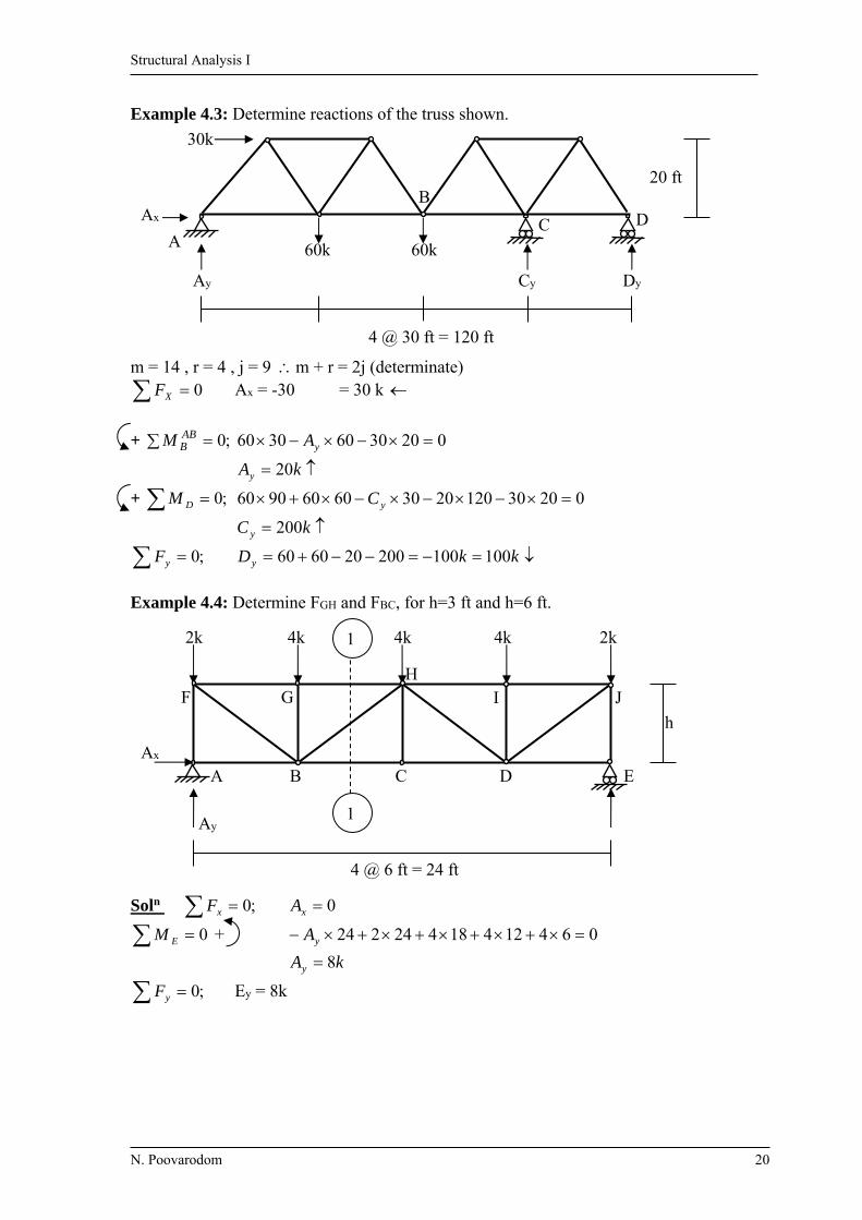
Example 4.3: Determine reactions of the truss shown.
m = 14 , r = 4 , j = 9 m + r = 2j (determinate)
0XF Ax = -30 = 30 k
+ ;0 ABBM 02030603060 yA
kAy 20
+ ;0 DM 02030120203060609060 yC
kC y 200
;0 yF kkDy 100100200206060
Example 4.4: Determine FGH and FBC, for h=3 ft and h=6 ft.
Soln ;0xF 0xA
0EM + 06412418424224 yA
kAy 8
;0yF Ey = 8k
20 ft
D C A
Ax
Ay Dy Cy
60k60k
30k
4 @ 30 ft = 120 ft
B
4 @ 6 ft = 24 ft
J I H
G F
E D C B A
2k 4k 4k 4k 2k
h
Ay
Ax
1
1

Structural Analysis I
N. Poovarodom 21
Section 1-1 + ;0HM
hF
hF
BC
BC
48
012864122
+ ;0BM
hF
hF
GH
GH
36
06268
For h = 3 ft FBC = 16 k (T) FGH = -12 k = 12 k (C)
For h = 6 ft FBC = 8 k (T) FGH = -6 k = 6 k (C)
For h =3
For h = 6
To compare the effectiveness of system in terms of the least weight of the structure, consider the weight from the volume of the structure. For Volume = LA
The required area of section is dependent on the internal force;all
FA
Therefore, Volume LF For h=3 )247.424.13(71.6)2428(3)216412(6ii LF
= 2159.7 unit h = 6 )283.2248.8(48.8)2428(6)2846(6ii LF
= 575.8 unit
8.48 8.48 2.83 2.83 4 4 8 8
6 6 6 6
8 8
0
0 0
13.4 13.4 4.47 4.47 4 4 8 8
12 12 12 12
16 16 0
0
0
h
4 2
8
B
FGH H
FBH
FBC
Structural Analysis I
N. Poovarodom 22
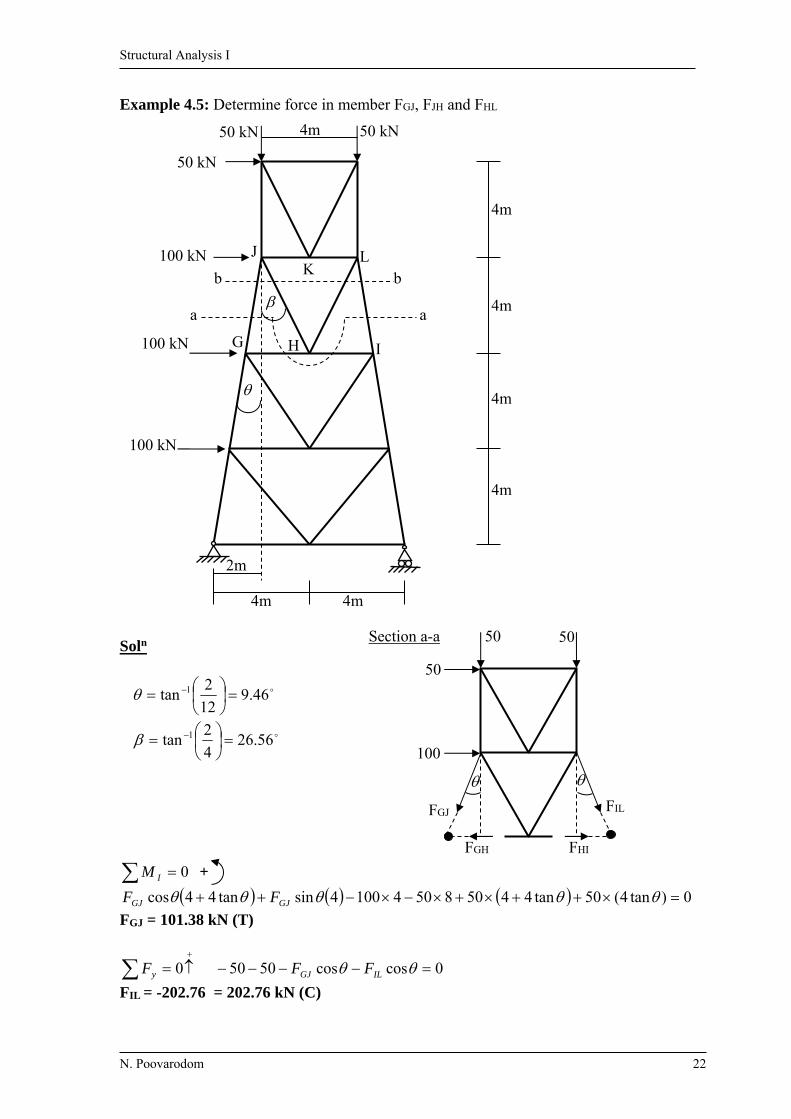
Example 4.5: Determine force in member FGJ, FJH and FHL
Soln
46.912
2tan 1
56.264
2tan 1
0IM +
0)tan4(50tan445085041004sintan44cos GJGJ FF
FGJ = 101.38 kN (T)
0yF 0coscos5050 ILGJ FF
FIL = -202.76 = 202.76 kN (C)
4m
4m
4m
4m
4m 4m
2m
4m 50 kN 50 kN
100 kN
50 kN
a a
b b L
K J
I H G
100 kN
100 kN
FGJ FIL
FHI FGH
50 50
50
100
Section a-a
Structural Analysis I
N. Poovarodom 23
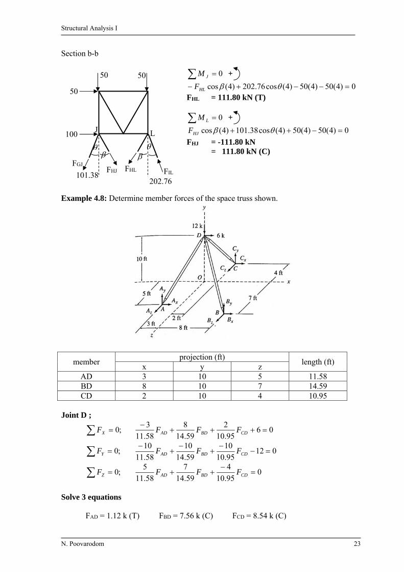
Section b-b
0JM +
0)4(50)4(50)4(cos76.202)4(cos HLFFHL = 111.80 kN (T)
0LM +
0)4(50)4(50)4(cos38.101)4(cos HJF
FHJ = -111.80 kN = 111.80 kN (C)
Example 4.8: Determine member forces of the space truss shown.
member projection (ft)
length (ft) x y z
AD 3 10 5 11.58 BD 8 10 7 14.59 CD 2 10 4 10.95
Joint D ;
;0XF 0695.10
2
59.14
8
58.11
3
CDBDAD FFF
;0YF 01295.10
10
59.14
10
58.11
10
CDBDAD FFF
;0ZF 095.10
4
59.14
7
58.11
5
CDBDAD FFF
Solve 3 equations FAD = 1.12 k (T) FBD = 7.56 k (C) FCD = 8.54 k (C)
50 50
50
100
FHL FHJ
202.76 101.38
J L
FGJ FIL

Structural Analysis I
N. Poovarodom 24
Example 4.9: Determine member forces of the space truss shown.
member projection (ft)
length (ft) x y z
AB 20 0 0 20 AC 14 0 10 17.2 BC 6 0 10 11.66 AD 10 20 5 22.91 BD 10 20 5 22.91 CD 4 20 5 21
Joint D
;0XF 02521
4
91.22
10
91.22
10
CDBDAD FFF
;0YF 03021
20
91.22
20
91.22
20
CDBDAD FFF
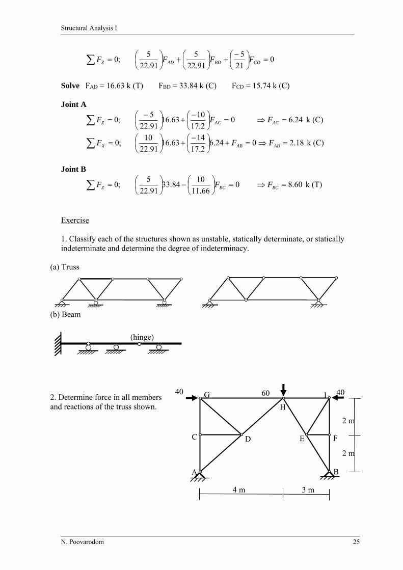
Structural Analysis I
N. Poovarodom 25
;0ZF 021
5
91.22
5
91.22
5
CDBDAD FFF
Solve FAD = 16.63 k (T) FBD = 33.84 k (C) FCD = 15.74 k (C) Joint A
;0ZF 02.17
1063.16
91.22
5
ACF 24.6 ACF k (C)
;0XF 024.62.17
1463.16
91.22
10
ABF 18.2 ABF k (C)
Joint B
;0ZF 066.11
1084.33
91.22
5
BCF 60.8 BCF k (T)
Exercise 1. Classify each of the structures shown as unstable, statically determinate, or statically indeterminate and determine the degree of indeterminacy.
(a) Truss
(b) Beam
2. Determine force in all members and reactions of the truss shown.
(hinge)
40 40 60
A B
C D E F
G
H
I
2 m
2 m
4 m 3 m

Structural Analysis I
N. Poovarodom 26
3. Determine force in members AD, BD, CD, AB and AC of the space truss shown.
y
z
A
C
D
25 kN 20 kN
4 m
B x
40 kN
3 m
2.5 m 3 m
1.5 (CX, CY , CZ)
(BX, BZ )
(AY)
2 m
1 m

Structural Analysis I
N. Poovarodom 27
Chapter 5 Beams and Frames: Shear and Bending Moment
5.1 Axial force, Shear and Bending moment Axial force “Q” Shear “S”, Moment: “M” Sign Convention (Beam Convention) * For inclined and vertical members, employ yx coordinate system y x-axis is in the direction of the member axis x y-axis is in the direction that make right – handed system with z-axis point out of paper y-axis should be upward direction and near the left portion of member 5.2 Shear Force Diagram (SFD) and Bending Moment Diagram (BMD) They depict the variations of shear and bending moment quantities along the length of the members 5.3 Qualitative Deflected Shapes “A rough sketch of the neutral surface of structure, in the deformed position, under the action of a given loading condition” (Deformation due to bending moment only) * Positive M bends a beam concave upward * Negative M bends a beam concave downward * Note From example, A and D must contain no deflection E may deflect upward or downward (can not indicate)
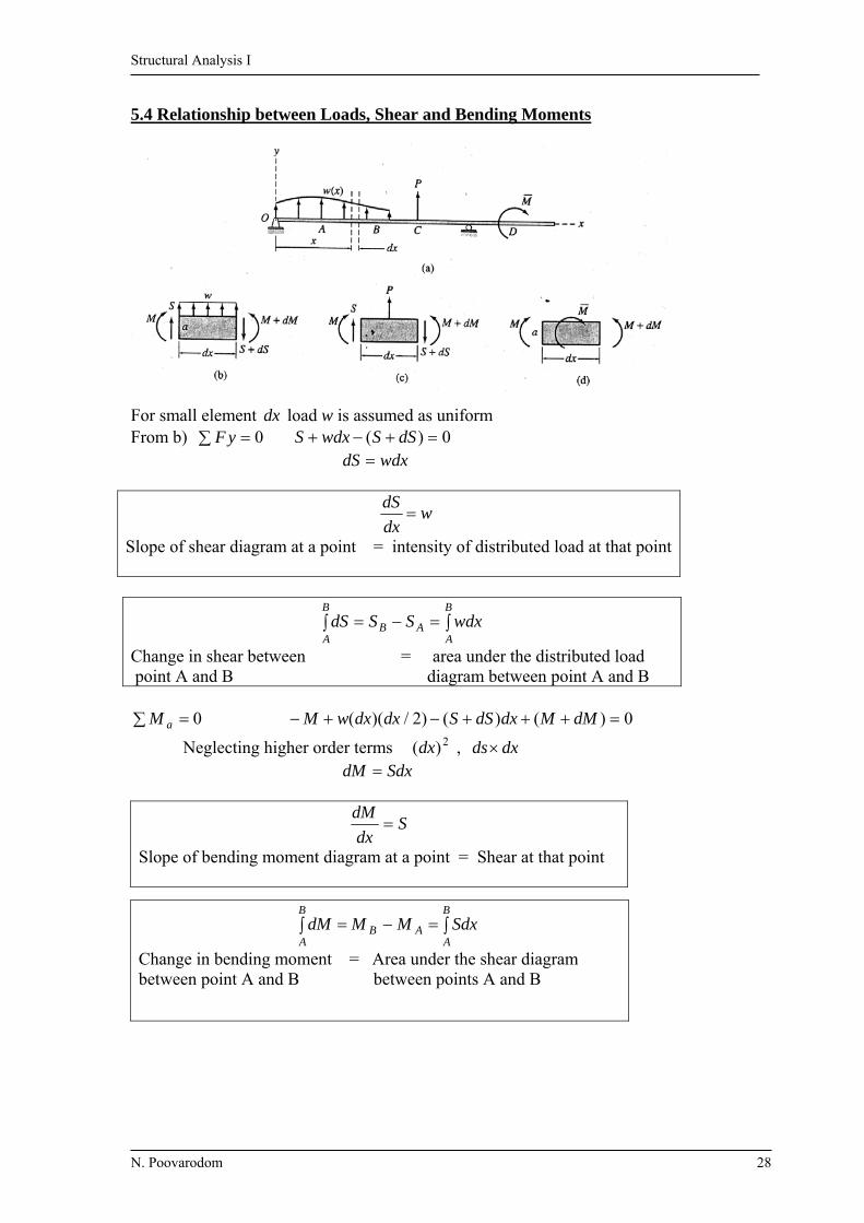
Structural Analysis I
N. Poovarodom 28
5.4 Relationship between Loads, Shear and Bending Moments For small element dx load w is assumed as uniform From b) 0 yF 0)( dSSwdxS wdxdS
wdx
dS
Slope of shear diagram at a point = intensity of distributed load at that point
B
AA
B
AB wdxSSdS
Change in shear between = area under the distributed load point A and B diagram between point A and B
0 aM 0)()()2/)(( dMMdxdSSdxdxwM
Neglecting higher order terms 2)(dx , dxds SdxdM
Sdx
dM
Slope of bending moment diagram at a point = Shear at that point
B
AA
B
AB SdxMMdM
Change in bending moment = Area under the shear diagram between point A and B between points A and B

Structural Analysis I
N. Poovarodom 29
For concentrated loads Fig c) 0 yF ; 0)( dSSPS
For couples or concentrated moments
Fig d) 0 aM ; 0)( dMMMM
MdM Change in bending moment at the = magnitude of the point of application of a couple moment of the couple
Procedure for analysis to construct SFD and BMD 1. Calculate the support reactions. 2. Construct SFD as follows;
a) Determine Shear at the left end of beam. Upward concentrate load cause shear to increase. Downward concentrate load cause shear to decrease. b) Identify the next point to calculate shear.
(Ex. the other end or point of concentrate load) c) Determine the shear at point from (b), from the area under the load diagram. d) Determine the shape of the shear diagram; the slope of SFD is equal to the
load intensity at that point. e) If there is a concentrated load at this end, calculate the ordinate of shear diagram caused by the load. f) Return to step (b) until the right end is reached. Shear must be zero at the end. (include reaction) 3 Construct BMD as follows; a) Determine moment at left end. Clockwise couple cause bending moment to increase. Counterclockwise couple cause bending moment to decrease.
b) Identify the next point to calculate moment. Usually at point where shear was computed, where the couples are applied and where max/min moments occur and where shear is zero.
c) Determine bending moment at point from (b), from the area under the shear diagram.
d) Determine the shape of the BMD; the slope of BMD is equal to the shear at that point. e) If there is a couple at this end, calculate the ordinate of BMD from the couple. f) Return to (b) until the right end is reached. Moment at the end must be zero. (include reaction)
PdS Change in shear at that point of = magnitude of the load application of a concentrated load

Structural Analysis I
N. Poovarodom 30
5.5 Static Determinacy, Indeterminacy and Instability of Plane Frame Statically Determinate = the bending moments, shears, and axial forces in all members, as well as the external reaction can be determined by using the equation of equilibrium and conditions. Example; Unknowns
6 per member + number of reactions
= (6 × 3) + 3 = 21
Equations 3 equations per member + 3 equations per joint = (3 × 3) + (3 × 4) = 21 Statically Determinate
Total Unknowns rmU 6
Total Equation
cejmE )(3
cejmrm )(36
or cejrm 33
necessary but not sufficient
“ ce ” Hinge; The number of equations of condition at the hinge joint is equal to the number
of members meeting at the joint minus one
0EHHM , 0GH
HM , 0 IHHM
They are not independent, one equation is automatically satisfied ( 1M trivial ) Roller: ce = 2 × (number of member at joint) – 2
(1 M , 1F trivial )
cejrm 33 Statically Unstable Frame
cejrm 33 Statically Determinate Frame
cejrm 33 Statically Indeterminate Frame
Structural Analysis I
N. Poovarodom 31
2
P2
P
L/2 L/2
x
P
2
P
2
P
4
PL
BMD
SFD
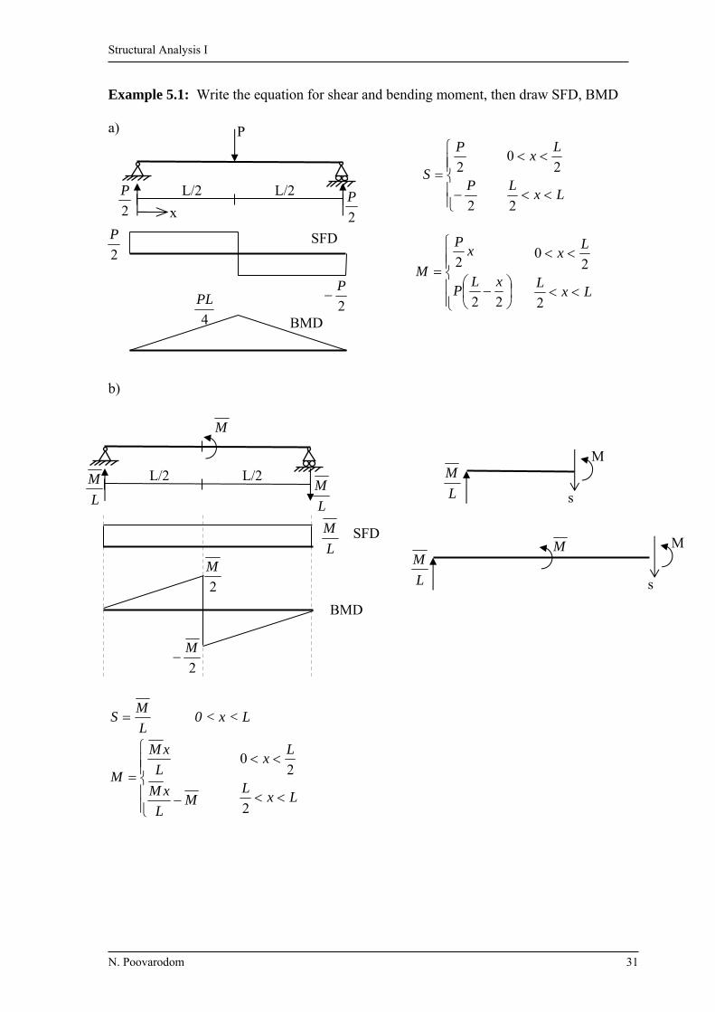
Example 5.1: Write the equation for shear and bending moment, then draw SFD, BMD a)
2
2P
P
S
LxL
Lx
2
20
22
2xL
P
xP
M
LxL
Lx
2
20
b)
L
MS 0 < x < L
ML
xM
L
xM
M
LxL
Lx
2
20
2
M
2
M
L
M
L
M L
M
L/2 L/2
M
SFD
BMD
M
s L
M
M M
s L
M

Structural Analysis I
N. Poovarodom 32
c)
;0 ABBM
3
303033.1
2
1
2
3030230 yA
kAy 67.36
;0yF 67.3645)42(2
1yC
kCy 33.98
;0AM +
0453
2452
2
1
2
454524533.98
CM
ftkM C .1050
45
2
x
z Then xz
45
2
xxxS
45
2
2
1267.36
45
267.362x
xS 0<x<L
3452267.36
2 xxxxxM
135
67.363
2 xxxM 0<x<L
For maximum M occurring at dx
dM = 0 = S
045
267.362
x
x x = 15.62 ft M = 300.6 k.ft
B A
-1050
300.6 -98.33
36.67
15.62
98.33 36.67
15 ft 30 ft
3.33 4k/ft
2k/ft
hinge C
1050 Ay
2 3.33
A B
x
z
2
36.67
S
M

Structural Analysis I
N. Poovarodom 33
Example 5.2 Draw SFD, BMD and qualitative deflection shape a) b)
c) d)
15kN/m
195.2 128
-24.4
5.625.6
12 ft 8 ft5 ft
BMD
SFD
24.425.6
30k 20k
Deflected shape
105110 110.2
-2.5
-52.5
57.552.557.5
2m2m 4m
50kN
3.83
75
-125
4 ft6 ft 10 ft
20
20
125k-ft 75k-ft20 k
203.6 226.8
176.8
-24.82
-2.32
17.68
1.5k-ft20k 50k-ft
15 ft10 ft
24.8217.68
10 ft

Structural Analysis I
N. Poovarodom 34
e) f)
To determine reaction in (f), consider part CE
0ACAM
13602
1313158 yB
kNBy 94.255
0yF 94.0yA kN94.0
0EGGM
2
13131013608 yF
kNFy 13.203
0yF kNkNGy 13.1313.13
35
-65 -31.25
23.2
8.4 ft 10
-21
16.5
-12.5
29 31
35k-ft
2.5k/ft
10 ft 5 ft 15 ft
10k
13.13203.13
-120.94
0.94
5m 5m 5m 5m 8m8m
GFE D CBA
120kN 10kN/m15kN/m
-0.94
255.94
135
60
-60 -110
93.1313.13
300
- 487.5 - 425
60 60
120
By Ay
15
60
60
Gy Fy
10
Structural Analysis I
N. Poovarodom 35
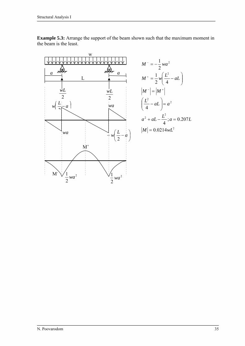
Example 5.3: Arrange the support of the beam shown such that the maximum moment in the beam is the least.
2
22
22
2
2
0214.0
207.0;4
4
42
1
2
1
wLM
LaL
aLa
aaLL
MM
aLL
wM
waM
2
2
1wa
2
2
1wa
M-
M+
a
Lw
2
a
Lw
2 wa
wa
2
wL
2
wL
L a
w
a

Structural Analysis I
N. Poovarodom 36
Example 5.4: Draw SFD, BMD and Axial force diagram, sketch the qualitative deflected shape.
-7
132.25
120
120 3.5 ft
-23
7
20
23 7
120
120
7
20
20
7
2k/ft 2k/ft
C B
A
6 ft
6 ft
23
15 ft
7
20
20 k FBD
SFD BMD
N-Diagram Deflected shape
x
y
x
y
x
y

Structural Analysis I
N. Poovarodom 37
Example 5.5: Draw SFD, BMD, Axial force diagram, sketch the qualitative deflected shape.
Reaction kNAx 60
;0AM
494.8108204408 yD
kNDy 7.84
kNAy 7.4
Ax
Ay
4m
4m
20 kN10 kN/m
40 kN
8 m
D
C
B
A
LBC=8.94 Dy
1.47
-66.813.15
60
4.47
8.9410
84.7
2020
84.7
84.7
66.8
(84.7)55.8
(20)
(4.7)
15.8
8.94 kN/m
240
(20)
60
40 20
4.7
4.7
4.7
4.7
240
60
60
56.26
84.7
SFD
240
240 4.47 kN/m
13.15
x
y
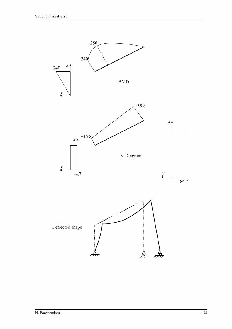
Structural Analysis I
N. Poovarodom 38
-84.7
+55.8
+15.8
-4.7
250
240
240
BMD
N-Diagram
Deflected shape
x
y
x
y
x
y

Structural Analysis I
N. Poovarodom 39
Example 5.6: Draw SFD, BMD and Axial force diagram, sketch the qualitative deflected shape.
Reaction
kAx 10
;0AM
kA
kD
D
y
y
y
83.8
17.27
1515202515302.130
1.2k/ft
10
25k
15 k
C
B
15 ft
15 ft
8.83 30 ft
DA
27.17
20 ft
-30.52
3.36
3.63
10
15
27.17
0.36
1.138
1.08
225
15
15
27.17
225
27.17
27.17
1515
225 225
(15)
5.64 (27.17)
30.52
3.6317.02
(8.83)
(15)
200
1.08k/ft15 25
10
8.83
8.83
200k-ft
8.83
10
10
8.83
LBC=31.62’
43.18
/138.162.31
302.1
ftkw
SFD
0.36 k/ft
x
y
+
x
y

Structural Analysis I
N. Poovarodom 40
-27.17
-5.64
-17.02
-8.83
206.1
200
-225 -225 200
BMD
Axial
Note: the angle at rigid connection remain unchanged.
x
y
y
x
y
x
y
x
Structural Analysis I
N. Poovarodom 41
Bx
10
25k
D C
1.25
A
ftkM A .75.181525.1
23.75
G
ftkM G .25.356
25
1.25
23.75 18.75
23.75
10 35
23.75
356.25
356.25
23.75
23.75
35
35
356.25
18.75
18.75
1.25
1.25
10
10
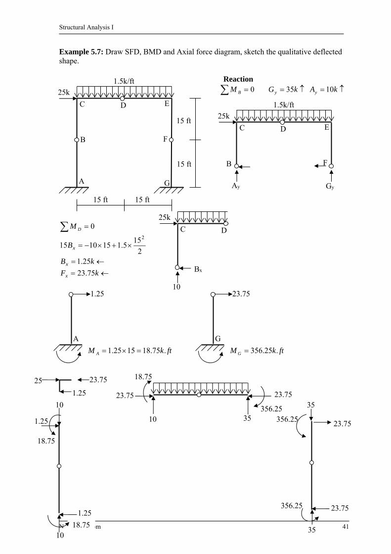
Example 5.7: Draw SFD, BMD and Axial force diagram, sketch the qualitative deflected shape.
Reaction 0BM kGy 35 kAy 10
0DM
kB
B
x
x
25.12
155.1151015
2
kFx 75.23
1.5k/ft
25k
15 ft
G
F
E D C
B
A
15 ft
15 ft 15 ft
Gy Ay
1.5k/ft
25k
F
E D C
B

Structural Analysis I
N. Poovarodom 42
-35
-23.75
-10
356.25
-356.25
-356.25
52.1 18.75
-18.75
18.75
23.75 -12.5 6.67
-35
10
1.25
SFD
BMD
Axial
y
x y
x
y
x
y
x
Structural Analysis I
N. Poovarodom 43
Chapter 6 Deflections of Beams: Geometric Methods
Cause of deformation: load, temperature change or support movement. Structures are usually designed so that their deflections under normal service conditions will not exceed the allowable values. 6.1 Differential equation for beam deflection Fig a: an initially straight elastic beam subjected to transverse load Elastic curve = the neutral surface of the beam in the deformed state. Fig b: a differential element dx
of the beam in its deformed position. Assume plane section remains plane and perpendicular to the neutral axis
The slope of elastic curve dx
dy
Assume is small
Then 02 , sin , 1cos d = change in slope over the differential
length dx Consider the deformation of a fiber ab located at a distance y from the neutral surface ''ba
yd
dyabbad
22 (Shortening)
The strain in ab is
R
y
Rd
yd
ds
d
(R = radius of curvature)
For E
, E = modulus of elasticity, = stress in ab
R
yE
From fig c, c maximum stress at extreme fiber, “c” from the neutral axis.
cc
y
For moment M = the summation of the moments about the neutral axis throughout cross sectional area.
A
ydAM for + (tension) , and - (compression)

Structural Analysis I
N. Poovarodom 44
Ic
dAyc
M C
A
C 2
I
McC A dAyI 2 = the moment of inertia
I
My
Then EI
M
R
1
From calculus;
232
22
1
1
dxdy
dxyd
R (Redefine y to be the vertical deflection.)
For small deformation 02 dxdy
2
21
dx
yd
R
The differential equations for the deflection of beams are; “Bernoulli–Euler beam equation”
dx
dy
, y can be solved.
Note: for small dxdy / the arc of elastic curve of beam “ ds ” is;
dxdxdxdydydxds 222 1
6.2 Direct Integration Method
- Writing EI
M in term of x
- Integrating this equation for , y. - Determining the constants of integration from boundary conditions.
This method is convenient for beams with continuous EI
M equation.
Note For linearly elastic beams subjected to several loads; The combined effect of loads = the algebraic sum of effect due to each of the loads acting individually on the beam.
EI
M
dx
yd
2
2
EI
M
dx
d

Structural Analysis I
N. Poovarodom 45
6.3 Moment-Area Method Moment-area theorem: Relations between the geometry of the elastic curve of
a beam to its EI
M diagram.
Consider a beam shown, we have
dxEI
Md
= infinitesimal area under EI
M
diagram Take integration
B
A
B
Adx
EI
Md
B
AABBA dx
EI
M ******
BA , slope of elastic curve at A and B, respectively with respect to the un-deformed axis of the beam
BA the angle between the tangents to the elastic curve at A and B
The first moment-area theorem: “The change in slope between the tangents to the elastic curve at any two points is
equal to the area under EI
M diagram between the two points, provided that the elastic curve
is continuous between the two points.” (There must be no discontinuity from internal hinge.)
* For positiveEI
M the angle from the tangent at the left point to the tangent
at the right point will be counterclockwise the positive change in slope.
For negativeEI
M vise versa
Consider the deviation "" d between the tangent at two ends of dx on a line perpendicular to the un-deformed axis from point B;
dxd
x distance from B to dx
dxxEI
Md
Take integration
dxxEI
Md
B
A
B
A
, Then dxx
EI
MB
ABA ****
Structural Analysis I
N. Poovarodom 46
BA The tangential deviation of B from the tangent at A = The deflection of B in the direction perpendicular to the un-deformed axis from the tangential at A
dxxEI
MB
A The moment of the area of
EI
M diagram between A to B, about point B
The second moment-area theorem: “The tangential deviation in the direction perpendicular to the un-deformed axis of the beam of a point on the elastic curve from the tangent to the elastic curve at another
point is equal to the moment of area under the EI
Mdiagram between the two points about
the point at which the deviation is desired, provided that the elastic curve is continuous between the two points.”
For positive EI
M between A to B, then BA is positive or B is above the tangent from A
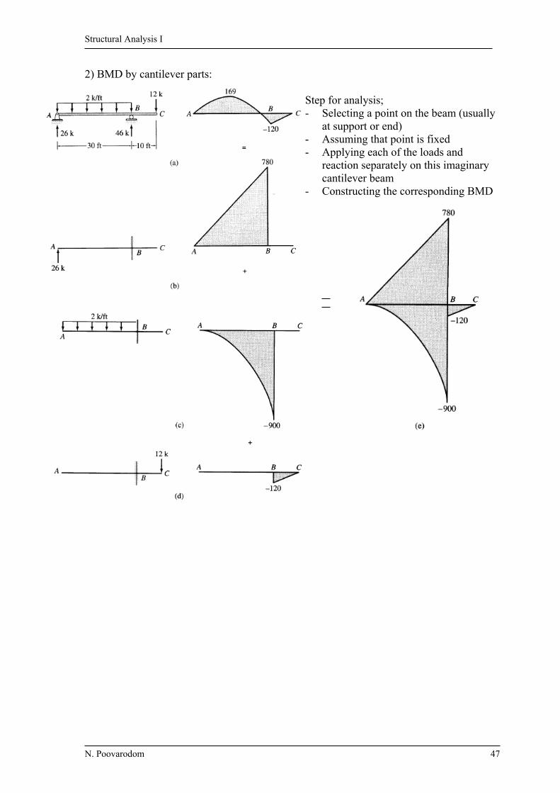
6.4 Bending Moment Diagram by Parts For a beam that is subjected to different types of loads (point load and distributed loads);
the EI
M diagram becomes irregular shape.
Solution: constructing a separate BMD or each load Simple geometric shape BMD The total effect is obtained by superposition. Approach 1) Apply each of the loads separately
Structural Analysis I
N. Poovarodom 47
2) BMD by cantilever parts:
Step for analysis; - Selecting a point on the beam (usually
at support or end) - Assuming that point is fixed - Applying each of the loads and
reaction separately on this imaginary cantilever beam
- Constructing the corresponding BMD

Structural Analysis I
N. Poovarodom 48
Chapter 7 Deflections of trusses, beams and frames:
Work-Energy method To analyze the deflections or displacements of statically determinate structures by
using basic principles of work and energy. This method is more general than other methods since it can be applied to various types of structures, such as trusses, beams and frames. However, only one deflection component at one point can be computed from one calculation.
7.1 Work
Work = force × displacement of its point of application in the direction of the force.
* Positive: When force and displacement have the same sense * Negative: When force and displacement have the opposite sense
Consider the work done by force P during the deformation of a structure under the action of a system of force. The magnitude of P may vary as its point of application displace from the original position to the final position.
The small work done dW from force P with infinitesimal displacement, d , is
dPdW
The total work done W of force P performs over the entire displacement is
dPW0
Structural Analysis I
N. Poovarodom 49
Consider 3 cases; From figure b): For general force-displacement relationship, W is equal to the area under the force-displacement diagram. From figure c): For linearly elastic structure, the force varies linearly with displacement from zero to its final value .Thus
PW2
1
From figure d): (special case), the force remains constant at P while its point of application undergoes a displacement cause by some other actions, then PW Also, the expressions for the work of couples are dMdW
- General case
0
MdW
- Linear elastic system
MW2
1
- Constant M during rotation MW
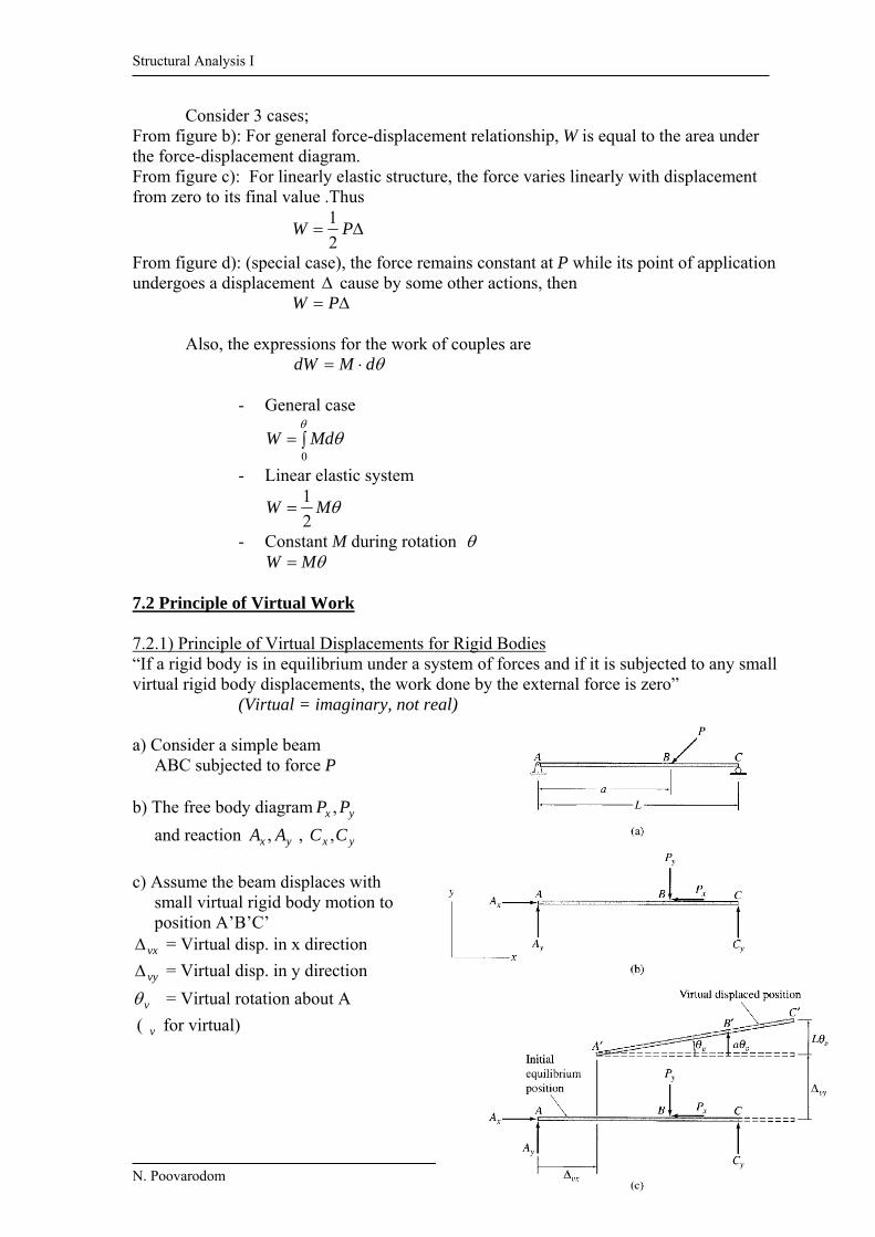
7.2 Principle of Virtual Work 7.2.1) Principle of Virtual Displacements for Rigid Bodies “If a rigid body is in equilibrium under a system of forces and if it is subjected to any small virtual rigid body displacements, the work done by the external force is zero” (Virtual = imaginary, not real) a) Consider a simple beam ABC subjected to force P b) The free body diagram yx PP ,
and reaction yx AA , , yx CC ,
c) Assume the beam displaces with small virtual rigid body motion to position A’B’C’
vx = Virtual disp. in x direction
vy = Virtual disp. in y direction
v = Virtual rotation about A
( v for virtual)

Structural Analysis I
N. Poovarodom 50
When the beam deforms, all forces acting on it perform work called “Virtual Work” The total virtual work done by external forces veW
vrvyvxve WWWW vxW = Virtual work done during translation in x vyW = Virtual work done during translation in y vrW = Virtual work done during rotation
vxxvxxxvxxvxxvx FPAPAW
vyyvyyyyvyyvyyvyyvy FCPACPAW
vAvyyvyvyvr MLCaPLCaPW
vAvyyvxxve MFFW Since for equilibrium 0 xF , 0 yF , 0 AM , then ** 0veW ** 7.2.2) Principle of Virtual Forces for Deformable Bodies “If a deformable structure is in equilibrium under a virtual system of forces (and couples) and if it is subjected to any small real deformation consistent with the support and continuity conditions of the structure, then the virtual external work done by the virtual external forces (and couples) acting through the real external displacement (and rotations) is equal to the virtual internal work done by the virtual internal forces (and couples) acting through the real internal displacements (and rotations).”
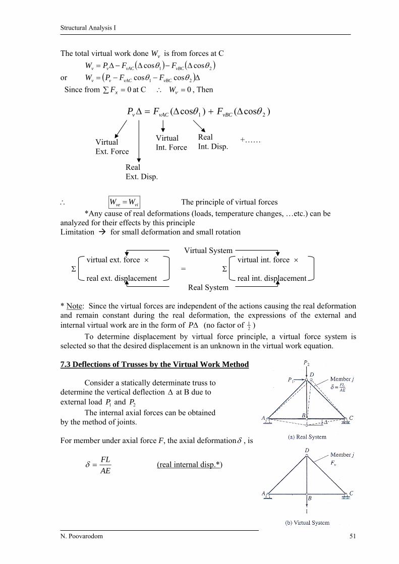
(Virtual ext. force) × (real ext. disp.) = (Virtual int. force) × (real int. disp.) To derive this principle, consider the two member truss shown a) Virtual external force vP b) FBD of joint C
Equilibrium of C ( vBCvAC FF , = Virtual int. force)
0 xF , 0coscos 21 vBCvACv FFP
0 yF , 0sinsin 21 vBCvAC FF
Assume that C displaces with a small real (Note: A and B are supports and not displace, then no work done at A and B)
Structural Analysis I
N. Poovarodom 51
The total virtual work done vW is from forces at C
21 coscos vBCvACvv FFPW
or 21 coscos vBCvACvv FFPW
Since from 0 xF at C 0W , Then
vive WW The principle of virtual forces
*Any cause of real deformations (loads, temperature changes, …etc.) can be analyzed for their effects by this principle Limitation for small deformation and small rotation
Virtual System virtual ext. force virtual int. force = real ext. displacement real int. displacement
Real System * Note: Since the virtual forces are independent of the actions causing the real deformation and remain constant during the real deformation, the expressions of the external and internal virtual work are in the form of P (no factor of 2
1 )
To determine displacement by virtual force principle, a virtual force system is selected so that the desired displacement is an unknown in the virtual work equation. 7.3 Deflections of Trusses by the Virtual Work Method Consider a statically determinate truss to determine the vertical deflection at B due to external load 1P and 2P The internal axial forces can be obtained by the method of joints. For member under axial force F, the axial deformation , is
AE
FL (real internal disp.*)
)cos()cos( 21 vBCvACv FFP
Virtual Ext. Force
Real Ext. Disp.
Virtual Int. Force
Real Int. Disp.
+……
Structural Analysis I
N. Poovarodom 52
To determine (real ext. disp.*), we select a virtual system with a unit load (virtual ext. force*) acting at B in the same direction as assumed )( . The internal force vF (virtual
int. force*) can be obtained by the method of joints. Now 1veW
And the total internal work done (summation of all members) )( vvi FW
For vive WW
Then )(1 vF
For the real internal deformation due to external load AE
FL
AE
FLFv1
Temperature Changes and Fabrication Errors For the member axial deformations are caused by temperature change T LT )( is the coefficient of thermal expansion of member Then )(1 TLFv
For the effect of fabrication errors, substitute changes in member length into the virtual work equation. Procedure for Analysis 1) Real System - External load: Obtain the real internal force F by method of joints. ( F is positive for tension ) - Temperature change: Consider the effect of increase of temperature as + T . - Fabrication error: Positive effects for too long member. 2) Virtual System - Remove all loads then apply a unit force at the joint to determine the deflection, in the direction of the deflection. - Compute all virtual internal force vF ( positive for tension)
3) can be obtained by applying the virtual work equation vF1
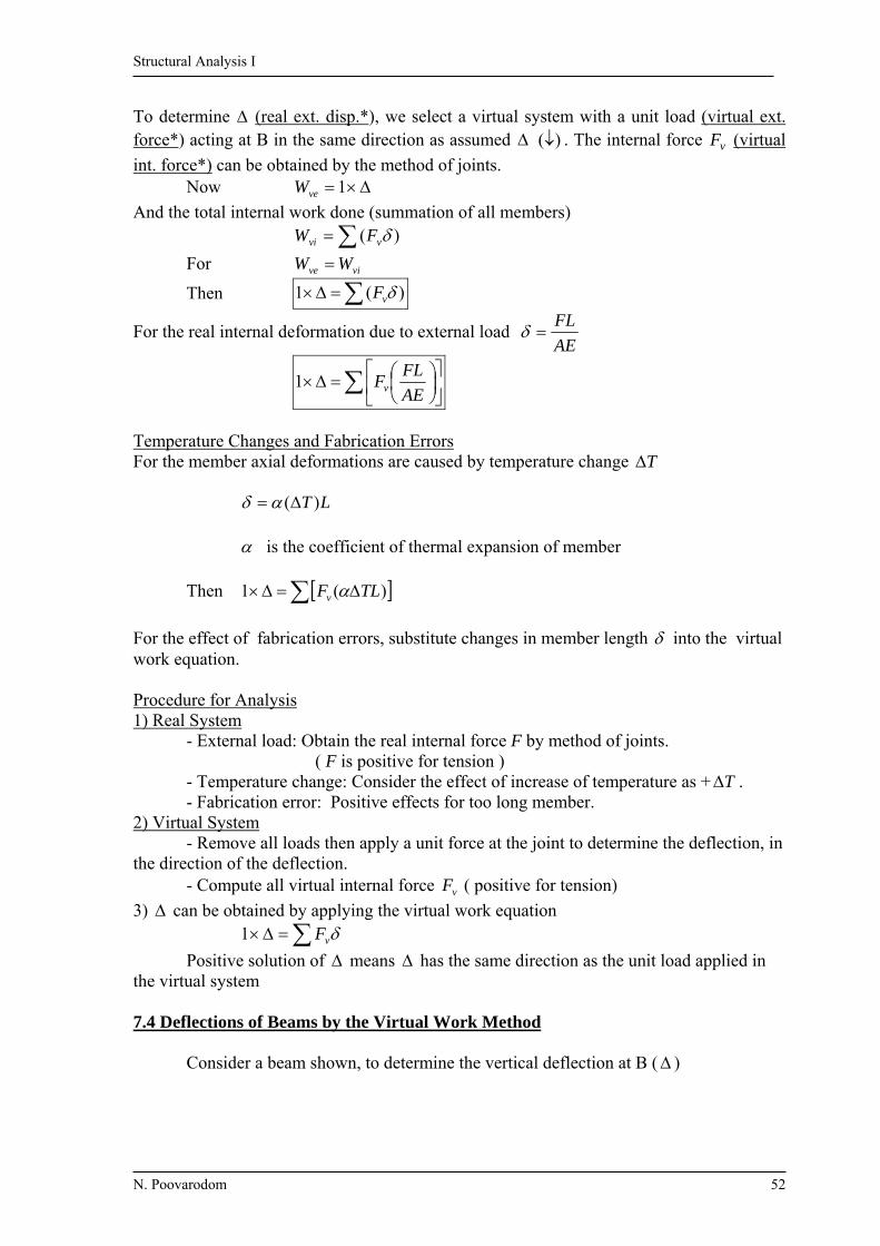
Positive solution of means has the same direction as the unit load applied in the virtual system 7.4 Deflections of Beams by the Virtual Work Method Consider a beam shown, to determine the vertical deflection at B ( )
Structural Analysis I
N. Poovarodom 53
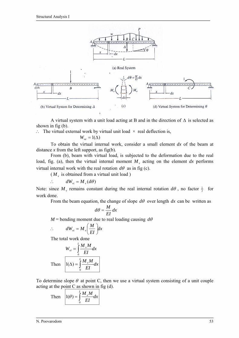
A virtual system with a unit load acting at B and in the direction of is selected as shown in fig (b). The virtual external work by virtual unit load × real deflection is, )(1 veW
To obtain the virtual internal work, consider a small element dx of the beam at distance x from the left support, as fig(b). From (b), beam with virtual load, is subjected to the deformation due to the real load, fig. (a), then the virtual internal moment vM acting on the element dx performs
virtual internal work with the real rotation d as in fig (c). ( vM is obtained from a virtual unit load )
)( dMdW vvi
Note: since vM remains constant during the real internal rotation d , no factor 21 for
work done. From the beam equation, the change of slope d over length dx can be written as
dxEI
Md
M = bending moment due to real loading causing d
dxEI
MMdW vvi
The total work done
dxEI
MMW
Lv
vi 0
Then dxEI
MMLv
0
)(1
To determine slope at point C, then we use a virtual system consisting of a unit couple acting at the point C as shown in fig (d).
Then dxEI
MMLv
0
)(1
Structural Analysis I
N. Poovarodom 54
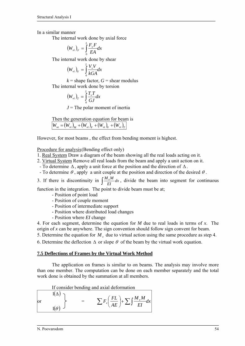
In a similar manner The internal work done by axial force
dxEA
FFW
Lv
Fvi 0
The internal work done by shear
dxkGA
VVW
Lv
Vvi 0
k = shape factor, G = shear modulus The internal work done by torsion
dxGJ
TTW
Lv
Tvi 0
J = The polar moment of inertia Then the generation equation for beam is TviVviFviMvive WWWWW
However, for most beams , the effect from bending moment is highest. Procedure for analysis (Bending effect only) 1. Real System Draw a diagram of the beam showing all the real loads acting on it. 2. Virtual System Remove all real loads from the beam and apply a unit action on it. - To determine , apply a unit force at the position and the direction of . - To determine , apply a unit couple at the position and direction of the desired .
3. If there is discontinuity in dxEI
MM v , divide the beam into segment for continuous
function in the integration. The point to divide beam must be at; - Position of point load - Position of couple moment - Position of intermediate support - Position where distributed load changes - Position where EI change 4. For each segment, determine the equation for M due to real loads in terms of x. The origin of x can be anywhere. The sign convention should follow sign convent for beam. 5. Determine the equation for vM due to virtual action using the same procedure as step 4.
6. Determine the deflection or slope of the beam by the virtual work equation. 7.5 Deflections of Frames by the Virtual Work Method The application on frames is similar to on beams. The analysis may involve more than one member. The computation can be done on each member separately and the total work done is obtained by the summation at all members. If consider bending and axial deformation
or
1
1 =
dxEI
MM
AE
FLF v
v

Structural Analysis I
N. Poovarodom 55
7.6 Conservation of Energy and Strain Energy Energy of Structure: The capacity of structure for doing work. Strain Energy “U”: The energy that a structure has because of its deformation. The principle of conservation of energy “The work performed on an elastic structure in equilibrium by statically (gradually) applied external forces is equal to the work done by the internal forces, or the strain energy of the structure.” ie WW
or UWe
Strain Energy of Trusses Consider a truss subjected to P P increases from zero to its final value For elastic structure, the deformation also increases linearly with the load
PWe 21
To write U, consider an arbitrary member j (for example, member CD)
If F = axial force in member due to load P Then = the axial deformation of this member
AE
FL
The internal work or strain energy stored in member j, jU is
AE
LFFU j
2
2
1
2
1
The strain energy for the entire truss is
AE
LFU
2
2
Strain Energy of Beams Consider a beam shown Force P increases from 0 P The internal bending moment M on element dx also increases from zero to its final value. The internal work or the strain energy in the element dx is
MddU2
1
For dxEI
Md

Structural Analysis I
N. Poovarodom 56
dxEI
MdU
2
2
1
Then dxEI
MU
L
0
2
2
* If EI
M is not a continuous function of x, the beam must be divided into segments
of continuous EI
M.
Strain Energy of Frames The portions of frames may be subjected to axial forces and bending moment, then ba UUU
For the frame with divided segments of constant AE
F,
AE
LFU a 2
2
For the frame with divided segments of constant EI
M
dxEI
MU b
2
2
The total strain energy
dxEI
M
AE
LFU
22
22
7.7 Castigliano ’s second Theorem “For linearly elastic structures, the partial derivative of the strain energy with respect to an applied force (or couple) is equal to the displacement (or rotation) of the force (or couple) along its line of action.”
iiP
U
or iiM
U
U = strain energy i = deflection of the point of application of iP , in the direction of iP .
i = rotation of the point of application of iM , in the direction of iM
To prove the theorem, consider a beam under force 321 ,, PPP
321 ,, PPP increase from zero causing
321 ,, which vary linearly with
the applied force.
Structural Analysis I
N. Poovarodom 57
dP2
dU
U
P2
dP2
dU
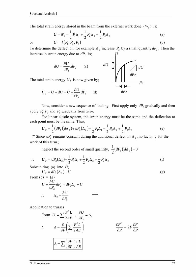
The total strain energy stored in the beam from the external work done ( eW ) is;
332211 2
1
2
1
2
1 PPPWU e (a)
or 321 ,, PPPfU (b)
To determine the deflection, for example, 2 increase 2P by a small quantity 2dP . Then the
increase in strain energy due to 2dP is;
22
.dPP
UdU
(c)
The total strain energy TU is now given by;
22
dPP
UUdUUU T
(d)
Now, consider a new sequence of loading. First apply only 2dP gradually and then
apply 21 , PP and 3P gradually from zero.
For linear elastic system, the strain energy must be the same and the deflection at each point must be the same. Thus,
3322112222 2
1
2
1
2
1
2
1 PPPdPddPU T (e)
(* Since 2dP remains constant during the additional deflection 2 , no factor 21 for the
work of this term.)
neglect the second order of small quantity, 02
122 ddP
33221122 2
1
2
1
2
1 PPPdPU T (f)
Substituting (a) into (f) UdPU T 22 (g) From (d) = (g)
UdPdPP
UU
2222
2
2 P
U
***
Application to trusses
From AE
LFU
2
2
, iiP
U
AE
LF
P 2
2
P
FF
P
F
22
AE
FL
P
F

Structural Analysis I
N. Poovarodom 58
Application to breams
L
dxEI
M
P 0
2
2 and
L
dxEI
M
M 0
2
2
or and Application to Frames
dxEI
M
P
M
AE
FL
P
F
dxEI
M
M
M
AE
FL
M
F
Procedure for analysis 1. 1.1) If there is an external force (or couple) acting on the given structure at the point and in the direction of the desired deflection (or rotation), then that force (or couple) may be used as P or M . Then, go to step 2 1.2) Otherwise, apply a fictitious load P or couple M correspondent to the desired unknown displacement or rotation. 2. Determine - the axial force F - the equations for bending moment )(xM in each member in terms of P and M 3. Determine
- P
F
- P
M
or - M
F
- M
M
4. 4.1) For a case of 1.1, substitute the numerical value of P or M into the expression for F and )(xM and derivatives. 4.2) For a case of 1.2, the numerical value is zero. 5. Determine , by the Castigliano’s second theorem
The positive results indicate the same direction as P or M
dxEI
M
P
ML
0
dxEI
M
M
ML
0
Structural Analysis I
N. Poovarodom 59
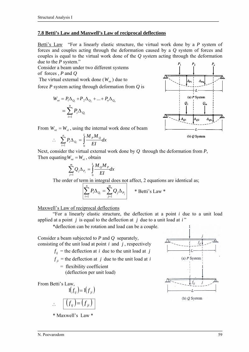
7.8 Betti’s Law and Maxwell’s Law of reciprocal deflections Betti’s Law “For a linearly elastic structure, the virtual work done by a P system of forces and couples acting through the deformation caused by a Q system of forces and couples is equal to the virtual work done of the Q system acting through the deformation due to the P system.” Consider a beam under two different systems of forces , P and Q The virtual external work done ( veW ) due to
force P system acting through deformation from Q is
nQnQQve PPPW ...21 21
n
iQi i
P1
From vive WW , using the internal work done of beam
dxEI
MMP
LQP
Q
n
ii i
01
Next, consider the virtual external work done by Q through the deformation from P, Then equating vive WW , obtain
dxEI
MMQ
LPQ
m
jPj j
01
The order of term in integral does not affect, 2 equations are identical as;
m
jPj
n
iQi ji
QP11
* Betti’s Law *
Maxwell’s Law of reciprocal deflections “For a linearly elastic structure, the deflection at a point i due to a unit load applied at a point j is equal to the deflection at j due to a unit load at i ” *deflection can be rotation and load can be a couple. Consider a beam subjected to P and Q separately, consisting of the unit load at point i and j , respectively
ijf = the deflection at i due to the unit load at j
jif = the deflection at j due to the unit load at i
= flexibility coefficient (deflection per unit load) From Betti’s Law, jiij ff 11
* Maxwell’s Law *
jiij ff

Structural Analysis I
N. Poovarodom 60
Example 7.1: Determine the vertical and horizontal deflection at B.
E = 200 GPa A = 1000 mm2 EA = 2 × 10⁵ kN
Sol n Real System: analyze the reaction and
member axial forces Virtual System:
1) for BH : apply a unit load in the horizontal direction at B
2) for BV : apply a unit load in the vertical
direction at B
Calculation for B : form a table contain the real forces F and virtual force Fv with EA , L Member L(m) F (kN) Fv1 Fv2 Fv1FL Fv2FL
AB 4.24 -5.66 0.849 -0.566 -20.37 13.58 AC 5 24 0.4 0.4 48.0 48.0 BC 3.61 -43.27 -0.721 -0.721 112.62 112.62
∑ 140.25 174.2
From Wvi = )(AE
FLFv = )(
1FLF
EA v
And Wve = )(1 Wve = Wvi
BH = EA
25.140 =
5102
25.140
= 0.000701 m = 0.701 mm
BV = EA
2.174 = 0.000871 m = 0.871 mm
40kN
A C
B 20kN
3 m
3 m 2 m
36
5.66 43.27
24 4
20
40
20 F-Force
0.6
1
0.849 0.721
0.4 0.6
1
Fv1 - Force
0.6
0.566 0.721
0.4 0.4
1 Fv2 - Force

Structural Analysis I
N. Poovarodom 61
Example 7.2: Obtain BH and BV , E= 29000 ksi
Soln Real system
F
Virtual 1 Virtual 2 Fv1 Fv2
Member L(in) A(in2) F (k) Fv1 (k/k) Fv1
A
FLFv2 (k/k) Fv2
A
FL
AB 240 4 33.33 0.889 1777.8 0 0 BC 240 4 33.33 0.444 887.9 -1 -1999.8 CD 240 4 33.33 0.444 887.9 -1 -1999.8 EF 240 4 -33.33 -0.889 1777.8 0 0 AE 300 4 -41.67 -1.110 3469.0 0 0 BF 300 3 0 0.556 0 0 0 DF 300 4 -41.67 -0.556 1737.6 0 0 BE 180 3 25 0.667 1000.5 0 0 CF 180 3 25 0 0 0 0
11538.5 -3999.6
BV = 29000
5.11538 = 0.398 in
BH = 29000
6.3999 = -0.138 in = 0.138 in
D C B A
(4in2)
(4) (3)
E F (4)
(3)
(4)
(3)
(4)
(4)
25k 25k
20 ft 20 ft 20 ft
15 ft
25
41.67 41.67 0 25 25
33.33 33.33 33.33
25
33.33
25 25
0.556 0.556 0.667 0
0.889 0.444 0.444
2/3 1/3
0.889
1
1.11 0
0
0
0
0
1
0 0
1 1
Structural Analysis I
N. Poovarodom 62
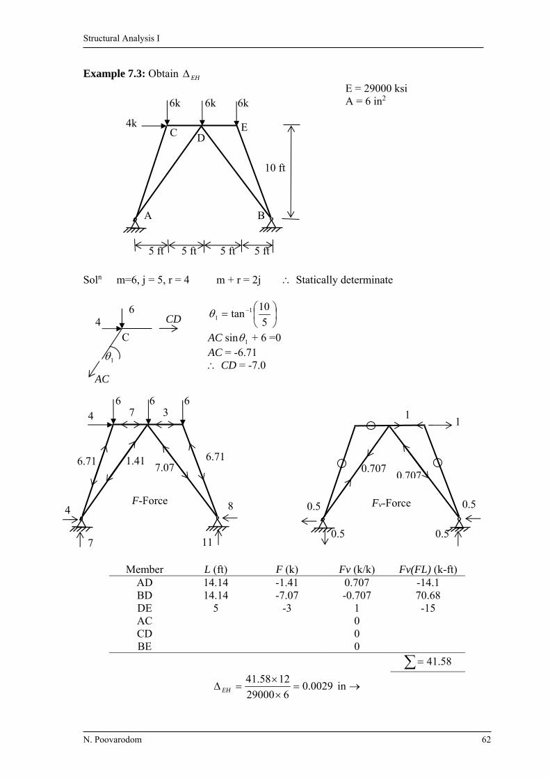
Example 7.3: Obtain EH E = 29000 ksi A = 6 in2
Soln m=6, j = 5, r = 4 m + r = 2j Statically determinate
5
10tan 1
1
AC sin 1 + 6 =0 AC = -6.71 CD = -7.0
Member L (ft) F (k) Fv (k/k) Fv(FL) (k-ft) AD 14.14 -1.41 0.707 -14.1 BD 14.14 -7.07 -0.707 70.68 DE 5 -3 1 -15 AC 0 CD 0 BE 0
58.41
in 0029.0629000
1258.41EH
ED C
BA
6k 6k 6k
4k
10 ft
5 ft 5 ft 5 ft 5 ft
37
6.71 1.41 7.07
6.71
8
11
4
6 6 6 4
7
F-Force
1
0.707
1
0.5
0.5 0.5
0.5
0.707
Fv-Force
CD
AC
1
6 4
C

Structural Analysis I
N. Poovarodom 63
50 50
100
50 50
100
Example 7.4: Determine the smallest A required for the structure shown so that the horizontal displacement at D (DH) does not exceed 10 mm, E = 70 GPa a)
Member L (m) F (kN) Fv Fv(FL) AB 3 0 0 0 CD 3 -100 0 0 AC 4 -50 0 0 BD 4 -183.3 -1.33 975.32 AD 5 166.7 1.67 1391.67
2367
1 (DH) = kN.m 2367
EA
For DH = 0.01 m = A61070
2367
A = 0.00338 m2 = 3380 mm2
b) c)
Arequired = 3050 2mm Arequired = 2621 2mm
183.3
50 kN
D C
B A
83.3
166.7
50kN 100 kN
50
100 kN
4 m 183.3
10
3 m
F-Force
1.33 1.33
1.33 1.67
1
1
Fv-Force

Structural Analysis I
N. Poovarodom 64
Example 7.5: Determine the vertical displacement at G ( vG ) due to temperature increase
of 65 F in AB, BC, CD and DE and a temperature drop of 20 F in FG and GH
= 6.5x 610 F
1
vF - Force
Member )( FT vF (k/k) vF )( T (k. F)
AB 65 -0.5 -32.5 BC 65 -1 -65 CD 65 -1 -65 and L are DE 65 -0.5 -32.5 identical FG -20 0.5 -10 GH -20 0.5 -10
215
TFLG vv
= )215(12105.6 6 = -0.0168 ft
= in 202.0 Example 7.6: Obtain vG if member BC and CG are made too short of 0.5 in.
member in Fv vF
BC -0.5 -1 0.5 CG -0.5 0 0
5.0
G = vF
= in 5.0
-20 -20
+65 +65 +65 +65
12 ft
C D E
F G H
B A
Real System
12 ft 12 ft 12 ft
12 ft
1
0.5
0.707 0.707
0.707 0.707
0.5 0.5
0.5 0.5
0.5 1 1 0.5
0.5

Structural Analysis I
N. Poovarodom 65
x
1
Example 7.7: Obtain and at A
EI = constant.
0<x<L 2
2wxM
0<x<L xM v 11
0<x<L 12 vM
for A
1 ( A ) = L
v dxEI
MM
0
1 = dxEI
wxxL
0
2
)2
)((
= L
EI
wx
0
4
8 =
EI
wL
8
4
For Ä
1 )( A = dxwx
EI
L
o
)2
)(1(1 2
= EI
wL
6
3
= EI
wL
6
3
w
L
A B
x
x
1
Real system
Virtual System 1 (for A )
Virtual System 2 (for A )
Structural Analysis I
N. Poovarodom 66
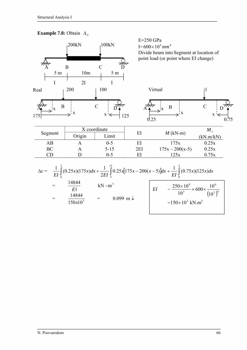
Example 7.8: Obtain C
E=250 GPa I= 4610600 mm Divide beam into Segment at location of point load (or point where EI change)
Segment X coordinate
EI M (kN-m) vM
(kN.m/kN)Origin Limit
AB A 0-5 EI 175x 0.25x BC A 5-15 2EI 175x – 200(x-5) 0.25x CD D 0-5 EI 125x 0.75x
c = 5
0
15
5
)5(20017525.02
1)175)(25.0(
1dxxxx
EIdxxx
EI 5
0
)125)(75.0(1
dxxxEI
= 1
14844
E 3mkN
= 310150
14844
x = m 099.0
5 m 10m 5 m B C D A
100kN 200kN
I I 2I
x x
x B C D A
125 175
Real 200 100
B C D A x
x x
0.75 0.25
1 Virtual
EI = 43
6
3
9
10
10600
10
10250
= 310150 kN.m2
Structural Analysis I
N. Poovarodom 67
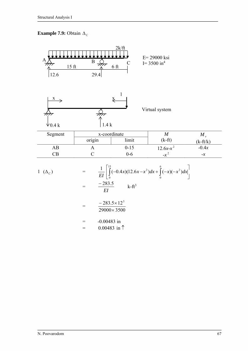
Example 7.9: Obtain C
E= 29000 ksi I= 3500 in4
Segment x-coordinate M (k-ft)
vM
(k-ft/k) origin limit
AB A 0-15 12.6x-x 2 -0.4x CB C 0-6 -x 2 -x
1 )( C = EI
1
15
0
6
0
22 ))(()6.12)(4.0( dxxxdxxxx
= EI
5.283 k-ft3
= 350029000
125.283 3
= -0.00483 in = in 00483.0
2k/ft
29.4 12.6
6 ft 15 ft B A
C
1
1.4 k 0.4 k
x x
Virtual system
Structural Analysis I
N. Poovarodom 68
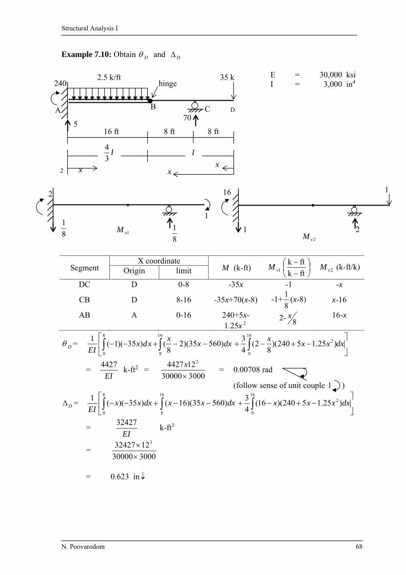
Example 7.10: Obtain D and D E = 30,000 ksi I = 3,000 in4
Segment X coordinate
M (k-ft) 1vM
ftk
ftk 2vM (k-ft/k) Origin limit
DC D 0-8 -35x -1 -x
CB D 8-16 -35x+70(x-8) -1+8
1(x-8) x-16
AB A 0-16 240+5x-1.25x 2
2- 8x 16-x
D =
16
8
8
0
)56035)(28
()35)(1(1
dxxx
xdxEI
dxxx
x16
0
2 )25.15240)(8
2(4
3
= EI
4427 k-ft2 =
300030000
124427 2
x
= 0.00708 rad
(follow sense of unit couple 1 )
D =
16
8
8
0
)56035)(16()35)((1
dxxxdxxxEI
16
0
2 )25.15240)(16(4
3dxxxx
= EI
32427 k-ft3
= 300030000
1232427 3
= 0.623 in
2
2
D 70
x x x
8 ft 8 ft 16 ft
240
5
C B A
35 k 2.5 k/ft hinge
I3
4 I
1
8
1 8
1
1vM 21
16 1
2vM

Structural Analysis I
N. Poovarodom 69
Example 7.11: Obtain D , consider only bending effect. E = 2000 ksi
I = 10000 in 4
Real M DE = 29x – 1.5x 2
Virtual M VDE = 16
x
D = dxxxx
EI)5.129(
162
1 216
0
= EI
3.469 k-ft2 =
)10000(2000
123.469 2
= 0.00338 rad
8 ft
8 ft
16 ft 8 ft
x
I 2I E
D C
B
A
30k
49
40
40k 29
3 k/ft
2I
M-system
16
1
16
1
1
vM only in member DE
Mv-system
Structural Analysis I
N. Poovarodom 70
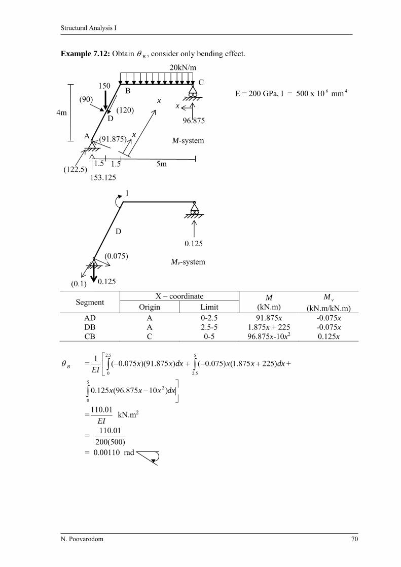
Example 7.12: Obtain B , consider only bending effect. E = 200 GPa, I = 500 x 10 6 mm 4
Segment X – coordinate M
(kN.m) vM
(kN.m/kN.m) Origin Limit AD A 0-2.5 91.875x -0.075x DB A 2.5-5 1.875x + 225 -0.075x CB C 0-5 96.875x-10x2 0.125x
B =
5.2
0
)875.91)(075.0(1
dxxxEI
5
5.2
)225875.1()075.0( dxxx +
dxxxx
5
0
2 )10875.96(125.0
=EI
01.110 kN.m2
= )500(200
01.110
= 0.00110 rad
5m
C B
A
D 96.875
xx
4m
1.5 1.5
(91.875)
(90) (120)
150
20kN/m
M-system x
153.125 (122.5)
D
1
0.125
0.125
(0.1)
(0.075) Mv-system

Structural Analysis I
N. Poovarodom 71
Example 7.13: Determine E (in vertical direction)
E = 200 GPa, I = 350x10 6 mm4
A = 6.5 x 104 mm2
(Approximately = square section)
5/2
1/2
5/12
5/12
1/2 1/2
5/12
5/12
1/2
5/2 5/2 5/2 5/12
5/12
1
1/2 1/2
5/12
1/2 1/2
5/12
1 kN
GFED
C
BA
Virtual System
(I,A)
(2I) (2I,2A) (2I,2A) (2I,2A)
(I,A)
H
G FE (hinge)
D C
BA
5m 5m 2m 3m
120.75
39.375
104.25
25.625
65 kN
3m
3m
15kN/m
104.25
30
30 39.375
120.75
236.25
x
39.375
x x
39.375
59.25 90.75
39.375
266.25 108.75 41.25
x
x
25.625
65
104.25
45
67.5
120.75
39.375
Structural Analysis I
N. Poovarodom 72
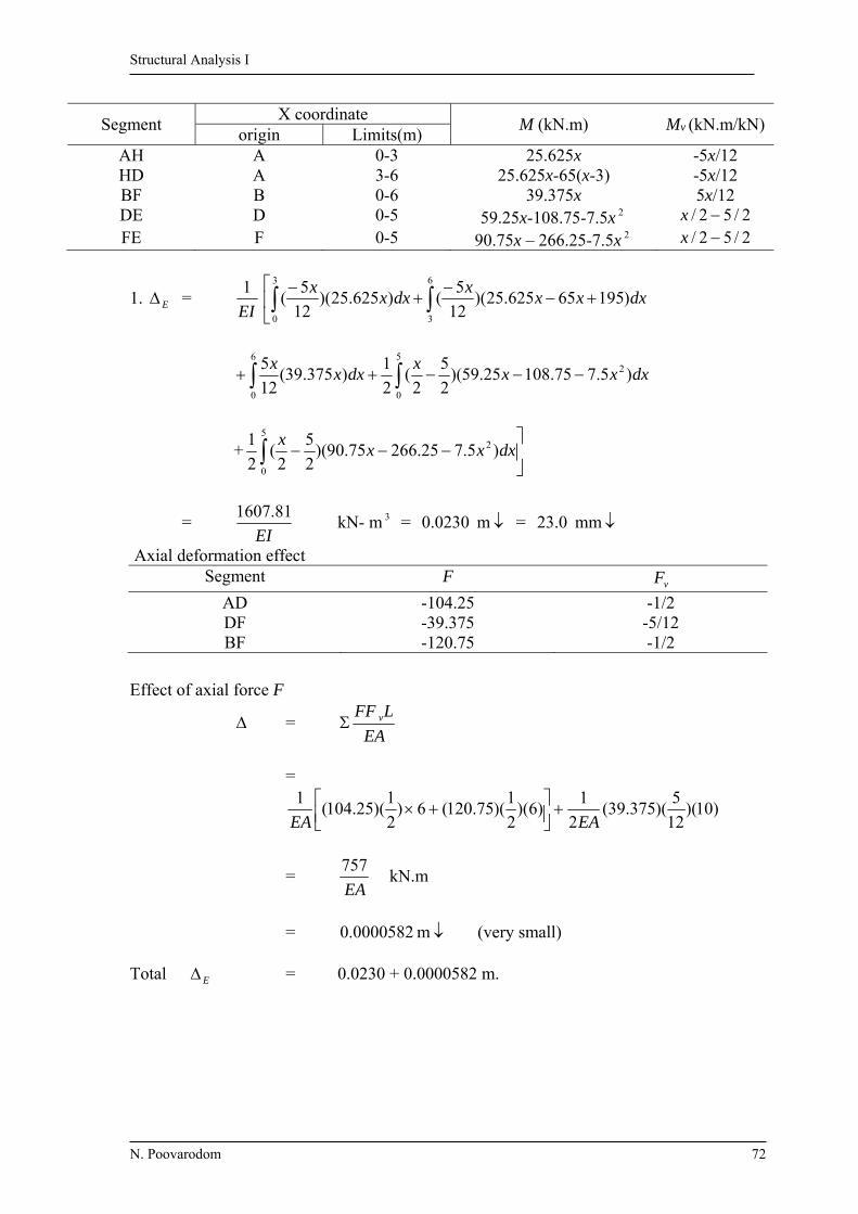
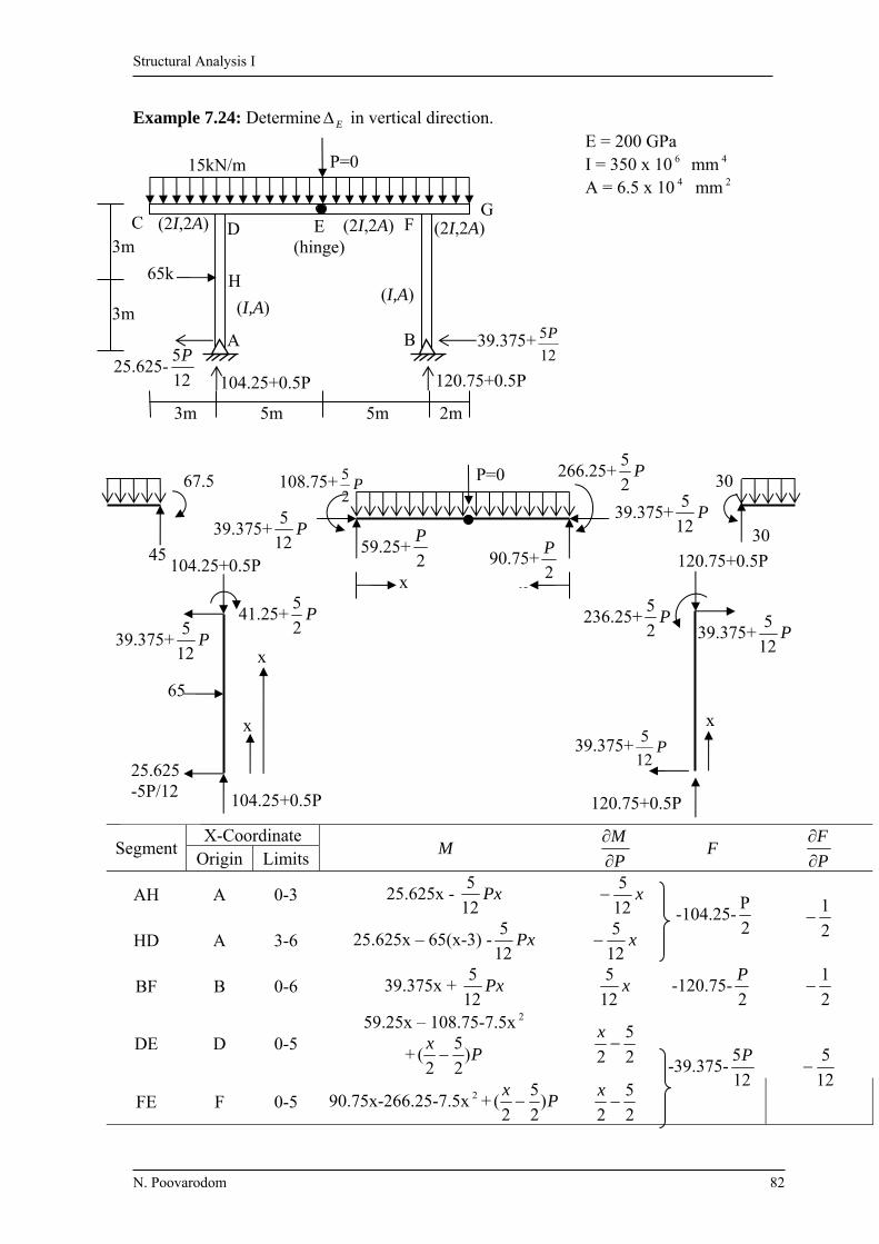
Segment X coordinate
M (kN.m) Mv (kN.m/kN) origin Limits(m)
AH A 0-3 25.625x -5x/12 HD A 3-6 25.625x-65(x-3) -5x/12 BF B 0-6 39.375x 5x/12 DE D 0-5 59.25x-108.75-7.5x 2 2/52/ x FE F 0-5 90.75x – 266.25-7.5x 2 2/52/ x
1. E = EI
1
3
0
6
3
)19565625.25)(12
5()625.25)(
12
5( dxxx
xdxx
x
dxxxx
dxxx
)5.775.10825.59)(2
5
2(
2
1)375.39(
12
5 25
0
6
0
+
5
0
2 )5.725.26675.90)(2
5
2(
2
1dxxx
x
= EI
81.1607 kN- m 3 = m 0230.0 = mm 0.23
Axial deformation effect Segment F
vF
AD -104.25 -1/2 DF -39.375 -5/12 BF -120.75 -1/2
Effect of axial force F
= EA
LFF v
=
)10)(12
5)(375.39(
2
1)6)(
2
1)(75.120(6)
2
1)(25.104(
1
EAEA
= EA
757 kN.m
= m 0000582.0 (very small) Total E = 0.0230 + 0.0000582 m.

Structural Analysis I
N. Poovarodom 73
Example 7.14: Determine C , consider effect of bending and axial deformation.
E = 70 GPa I = 1030 10 6 mm 4 A = 1.925 10 4 mm 2 EI = 72100 kN.m 2 EA = 1.3475 10 6 kN (WF 588 x 300)
Segment X coordinate
M (kN.m) Mv
(kN.m/kN) F (kN)
Fv (kN/kN) Origin Limit (m)
AB A 0-5 76x-530 -4 -48 -1 CB C 0-5 2/12 2x x)5/4( 0 -3/5
C1 = 5)1)(48(1
)2
12)(5
4()53076)(4(
1 5
0
25
0
EA
dxx
xdxxEI
= EAEI
240 kN.m
7550 3 kN.m = 0.10471 + 1.781 x 10 4 m
= 0.1049 m
1
C
A
B
3 m
4 m
530
48
76
40kN
x
x
12kN/m
5 m
1 (4/5) 1
4
1
4 1
4
11
x
4
60 150
150
36
48
40
530
48
76
xReal Virtual
(3/5)
Structural Analysis I
N. Poovarodom 74
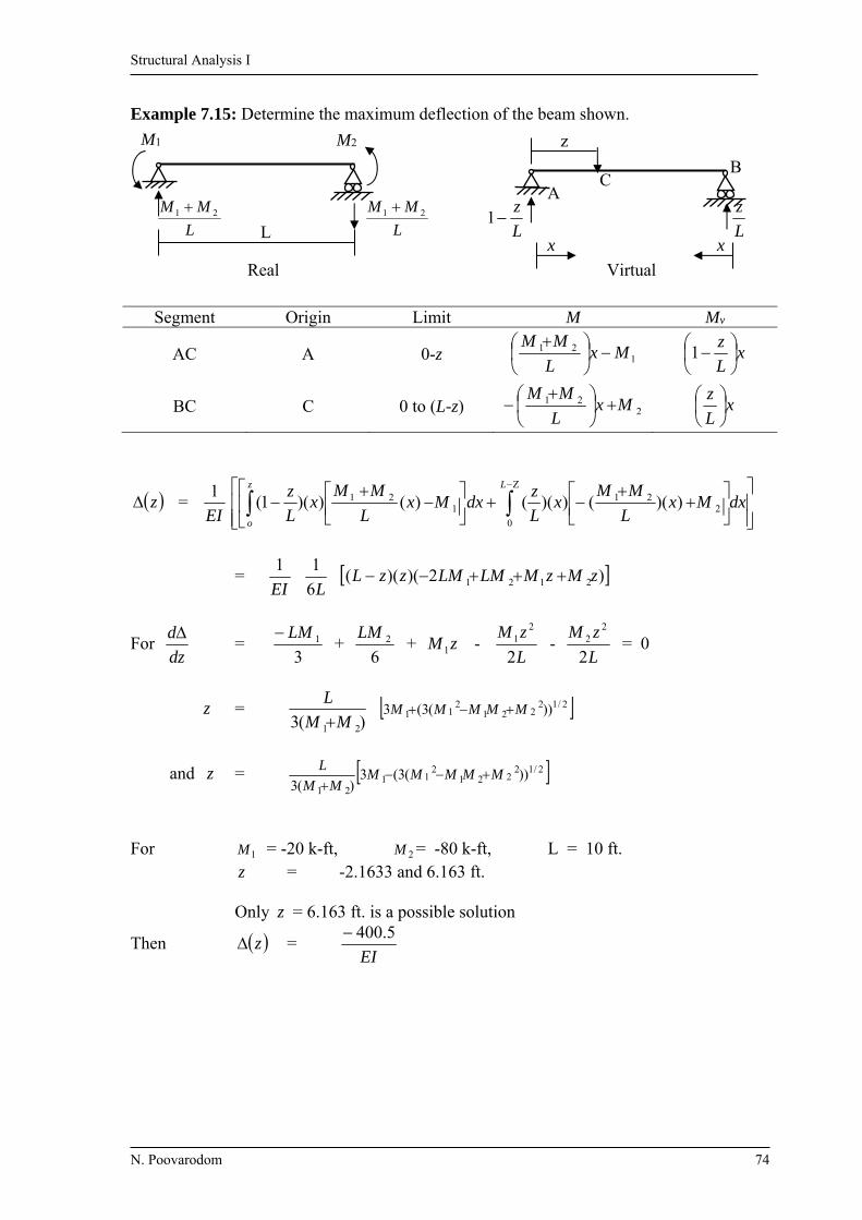
Example 7.15: Determine the maximum deflection of the beam shown.
Segment Origin Limit M Mv
AC A 0-z 121 Mx
L
MM
xL
z
1
BC C 0 to (L-z) 221 Mx
L
MM
xL
z
z = EI
1
dxMxL
MMx
L
zdxMx
L
MMx
L
z Lz
o 0
221
121 ))(())(()())(1(
= EI
1
L6
1 )2)()(( 2121 zMzMLMLMzzL
For dz
d =
31LM
+ 6
2LM + zM 1 -
L
zM
2
21 -
L
zM
2
22 = 0
z = )(3 21 MM
L
2/12
2212
11 ))(3(3 MMMMM
and z = 2/12221
211
21
))(3(3)(3
MMMMMMM
L
For 1M = -20 k-ft, 2M = -80 k-ft, L = 10 ft. z = -2.1633 and 6.163 ft. Only z = 6.163 ft. is a possible solution
Then z = EI
5.400
L
z
L
z1
xx
BC
A
z
L L
MM 21 L
MM 21
M1 M2
Real Virtual

Structural Analysis I
N. Poovarodom 75
Example 7.16: Determine BH and BV .
E = 200 GPa A = 1000 mm 2
Soln P1 and P2 act in the direction of BH and BV ,
then use them for variable of the analysis
Member L(m) F 1P
F
2P
F
P1 = 20, P 2 = 40
FLP
F
1
FLP
F
2
AB 4.24 0.849P1 -
0.566P 2 0.849 -0.566 -20.37 13.58
AC 5 0.4(P1 +P 2 ) 0.4 0.4 48 48
BC 3.61 -0.721(P1 +P 2 ) -0.721 -0.721 112.6 112.6
140.23 174.18
BH = EA
23.140
= 0.000701 m = mm 701.0
BV = EA
18.174
= 0.000871 m = mm 871.0
20kN
40kN
3m
2 m 3 m
C
B
A
P1 0.6P1 0.6P1
0.4P1
0.721P1 0.849P1
P1(=20kN)
0.721P0.566P2
0.4P2
0.6P2 0.4P2
P2(=40kN)

Structural Analysis I
N. Poovarodom 76
Example 7.17: Obtain BH and BV
E=29000 ksi
Member L(in) A(in 2 ) F 1P
F
2P
F
P1 = 0, P 2 = 25k
1P
F
)(A
FL
2P
F
)(A
FL
AB 240 4 11.11 + 0.889 P 2 0 0.889 0 1778.1
BC 240 4 22.22 - P1 +
0.444 P 2
-1 0.444 -1999.2 887.6
CD 240 4 22.22 - P1 +
0.444 P 2
-1 0.444 -1999.2 887.6
EF 240 4 -11.11 – 0.889P 2 0 -0.889 0 1778.1
AE 300 4 -13.89 – 1.11 P 2 0 -1.11 0 3466.5
BF 300 3 -13.89 + 0.556P 2 0 0.556 0 0
DF 300 4 -27.78 – 0.556P 2 0 -0.556 0 1738.1
BE 180 3 8.33 + 0.667P 2 0 0.667 0 1000.7
CF 180 3 25 0 0 0 0 = -3998.4 11536.7
367.16 2P
23
233.8 P
27.78+0.566P2 13.89- 0.556P2 25
8.33 + 0.667P2
13.89+1.11P2
11.11+0.889P2
11.11+0.889P2 22.22-P1+0.444P2 22.22-P1+0.444P2 P1
25k P2(=25k)
P1(=0)
D C B A
(4in2)
(4) (3)
E F (4)
(3)
(4)
(3)
(4)
(4)
25k 25k
20 ft 20 ft 20 ft
15 ft

Structural Analysis I
N. Poovarodom 77
BH = 29000
4.3998 = -0.138 in = in 138.0
BV = 29000
7.11536 = in 398.0
Example 7.18: Obtain EH
E = 29000 ksi A = 6 in2
Member L (in) F (k) P
F
)(
0
FLP
FP
AC 134.16 -6.71 0 0 BE 134.16 -6.71 0 0 AD 169.71 -1.41 + 0.707P 0.707 -169.18 BD 169.71 -7.07 – 0.707P -0.707 848.29 CD 60 -7 0 0 DE 60 -3+P 1 -180
499.11
EH = EA
11.499 = in 00287.0
10 ft
5 ft
24
P
A B
E D C
P(=0) 3-P 7
6.71 1.41- 0.707P
7.07 + 0.707P
6.71
28
P
211
P
27
P
6k 6k 6k
4k
E
5 ft 5 ft 5 ft
Structural Analysis I
N. Poovarodom 78
x
2k/ft
29.4+1.4P 12.6-0.4P
6 ft 15 ft B A
C
x
P (=0)
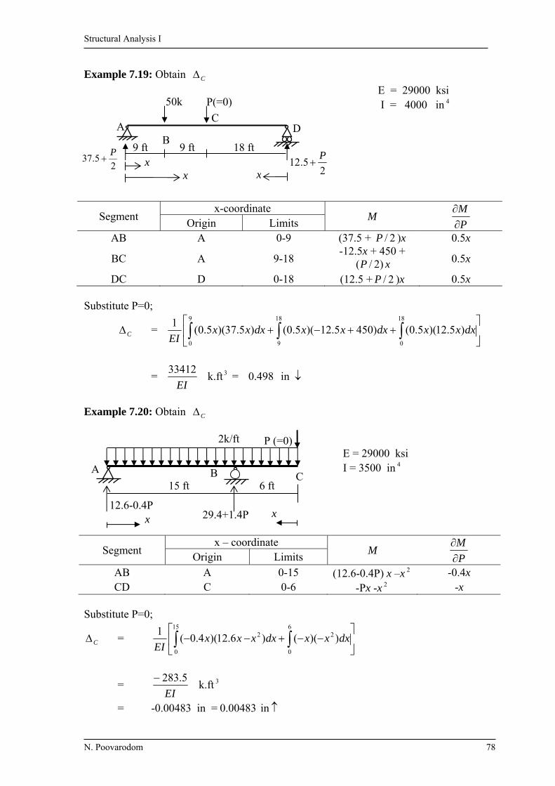
Example 7.19: Obtain C
E = 29000 ksi I = 4000 in 4
Segment x-coordinate
M P
M
Origin Limits
AB A 0-9 (37.5 + 2/P )x 0.5x
BC A 9-18 -12.5x + 450 +
)2/(P x 0.5x
DC D 0-18 (12.5 + 2/P )x 0.5x Substitute P=0;
C =
18
0
9
0
18
9
)5.12)(5.0()4505.12)(5.0()5.37)(5.0(1
dxxxdxxxdxxxEI
= 3k.ft 33412
EI = in 498.0
Example 7.20: Obtain C
E = 29000 ksi I = 3500 in 4
Segment x – coordinate
M P
M
Origin Limits
AB A 0-15 (12.6-0.4P) x –x 2 -0.4x CD C 0-6 -Px -x 2 -x
Substitute P=0;
C =
15
0
6
0
22 ))(()6.12)(4.0(1
dxxxdxxxxEI
= EI
5.283 k.ft 3
= -0.00483 in = in 00483.0
25.12
P
xx x
18 ft9 ft 9 ft
P(=0) 50k
DC
BA
25.37
P

Structural Analysis I
N. Poovarodom 79
Example 7.21: Obtain D and D E = 30,000 ksi I BC = I CD = I
I AB = (4/3)I
Segment x– coordinate
M M
M
P
M
Origin Limits
DC D 0-8 -Px - -1 -x
CB D 8-16 -Px - +(2P+8
)(x-8) 2
8
x x-16
AB A 0-16 225.1)8
40()216320( xx
2-8
x 16-x
Substitute = 0 and P = 35 k
D =
8
0
16
8
16
0
2 )25.15240)(8
2(4
3)56035)(2
8()35)(1(
1dxxx
xdxx
xdxx
EI
= EI
7.4426 k.ft 2 = 0.00708 rad
D =
8
0
16
8
)56035)(16()35)((1
dxxxdxxxEI
16
0
2 )25.15240)(16(4
3dxxxx
= EI
7.32426 k.ft 3 = in 622.0
2P+8
x x x
8 ft 8 ft
320-16P-2
40-P-8
C B A
35 k 2.5 k/ft hinge
I=4000in4 I=3000in4
(P=35)
D
=0
16 ft

Structural Analysis I
N. Poovarodom 80
Example 7.22: Obtain D , consider only effect of bending deformation. E = 10,000 ksi I = 3,000 in 4
Segment X – coordinate
M M
M
Origin Limits
AB A 0-20 x50)700( -1
BC B 0-15 300 -1
DC D 0-10 x30 1
Substitute = 0
D =
20
0
15
0
10
0
)30)(1()300)(1()50700)(1(2
11dxxdxdxx
EI
= EI
4000 k.ft 2
= -0.0192 rad = 0.0192 rad
10 ft
10 ft
15 ft
=0
50
20k
(I)
D
A
B C
30k
(I)
700+
(2I)
300-
30
30
x
30 30 300-300-
x
50
50 300-
700+
x

Structural Analysis I
N. Poovarodom 81
Example 7.23: Obtain CH , consider only effect of bending deformation.
E = 10,000 ksi I = 1500 in 4
Substitute P=0
CH = 12
0
2 )5.118(5.11
dxxxxEI
= EI
3888 k-ft3
= in 448.0
Segment X – coordinate
M P
M
Origin Limits
AB A 0-18 Px x CB C 0-12 (18+1.5P)x-1.5x 2 1.5x
18 ft
12 ft
12 ft 18-1.5P
18+1.5P
(P=0)
P
x
x
D
A
B C
3k/ft
Structural Analysis I
N. Poovarodom 82
Example 7.24: Determine E in vertical direction. E = 200 GPa I = 350 x 10 6 mm 4 A = 6.5 x 10 4 mm 2
Segment X-Coordinate
M P
M
F P
F
Origin Limits
AH A 0-3 25.625x - Px12
5 x
12
5
-104.25-2
2
1
HD A 3-6 25.625x – 65(x-3) - Px12
5 x
12
5
BF B 0-6 39.375x + Px12
5 x
12
5 -120.75-
2
P
2
1
DE D 0-5 59.25x – 108.75-7.5x 2
+ Px
)2
5
2( 2
5
2
x
-39.375-12
5P
12
5
FE F 0-5 90.75x-266.25-7.5x 2 + Px
)2
5
2(
2
5
2
x
25.625-12
5P
P=0
(I,A)
(2I,2A) (2I,2A)
(I,A)
G FE
(hinge) D C
BA
5m 5m 2m 3m
120.75+0.5P
39.375+12
5P
104.25+0.5P
65k
3m
3m
15kN/m
(2I,2A)
H
120.75+0.5P 104.25+0.5P
30
30
39.375+ P12
5
120.75+0.5P
236.25+ P2
5
x
39.375+ P12
5
x x
39.375+ P12
5
59.25+2
P
90.75+2
P
39.375+ P12
5
266.25+ P2
5
108.75+ P2
5
41.25+ P2
5
x
x
25.625 -5P/12
65
39.375+ P12
5
104.25+0.5P 45
67.5 P=0
Structural Analysis I
N. Poovarodom 83
Substitute P=0 and calculate
E =
AE
FL
P
F+
dxEI
M
P
M
= )10)(12
5)(375.39(
2
1)6)(
2
1)(75.120(6)
2
1)(25.104(
1
EAEA
+
3
0
6
3
)19565625.25)(12
5()625.25)(
12
5(
1dxxx
xdxx
x
EI
+ 6
0
5
0
2 )5.775.10825.59)(2
5
2(
2
1)375.39)(
12
5( dxxx
xdxx
x
+
5
0
2 )5.725.26675.90)(2
5
2( dxxxx
= EA
757 +
EI
81.1607
= m 0230.00000582.0
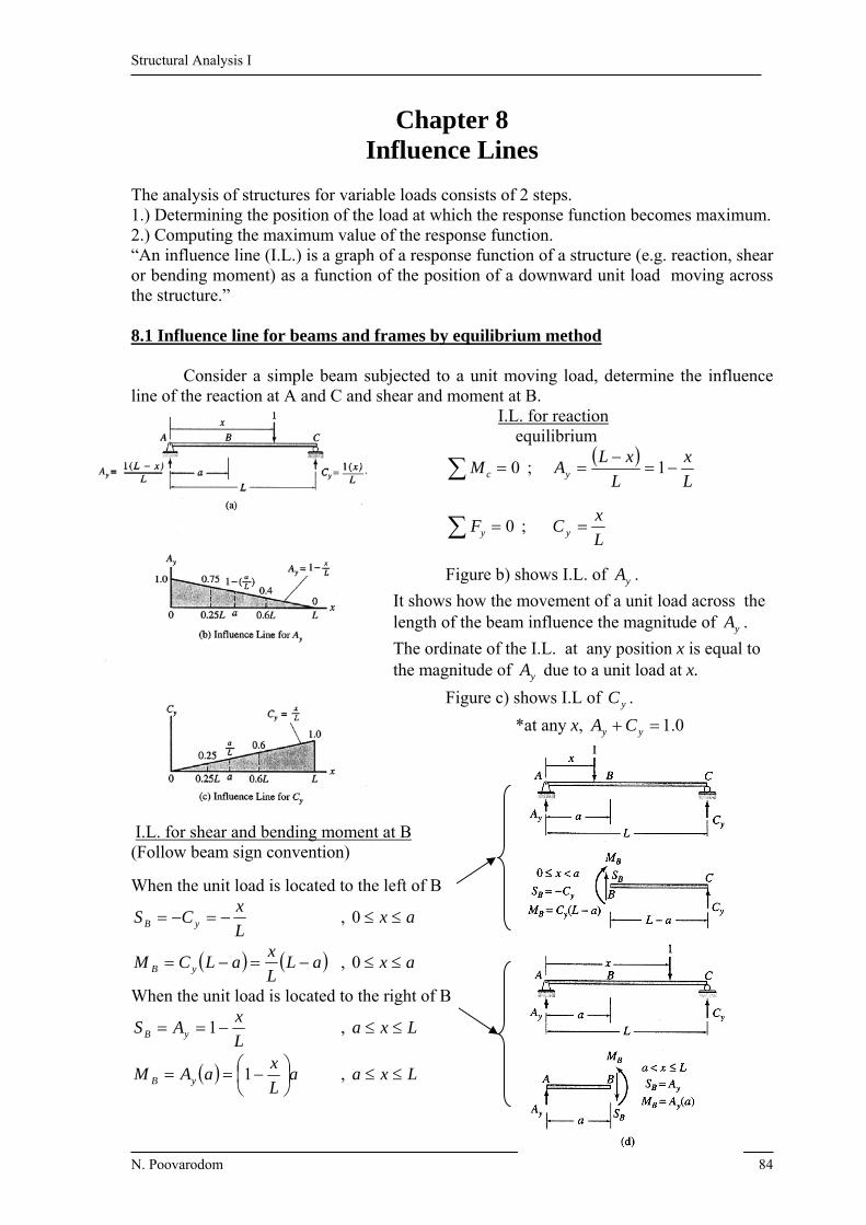
Structural Analysis I
N. Poovarodom 84
Chapter 8 Influence Lines
The analysis of structures for variable loads consists of 2 steps. 1.) Determining the position of the load at which the response function becomes maximum. 2.) Computing the maximum value of the response function. “An influence line (I.L.) is a graph of a response function of a structure (e.g. reaction, shear or bending moment) as a function of the position of a downward unit load moving across the structure.” 8.1 Influence line for beams and frames by equilibrium method Consider a simple beam subjected to a unit moving load, determine the influence line of the reaction at A and C and shear and moment at B. I.L. for reaction equilibrium
0 cM ;
L
x
L
xLAy
1
0 yF ; L
xC y
Figure b) shows I.L. of yA .
It shows how the movement of a unit load across the length of the beam influence the magnitude of yA .
The ordinate of the I.L. at any position x is equal to the magnitude of yA due to a unit load at x.
Figure c) shows I.L of yC .
*at any x, 0.1 yy CA
I.L. for shear and bending moment at B (Follow beam sign convention)
When the unit load is located to the left of B
L
xCS yB , ax 0
aLL
xaLCM yB , ax 0
When the unit load is located to the right of B
L
xAS yB 1 , Lxa
aL
xaAM yB
1 , Lxa
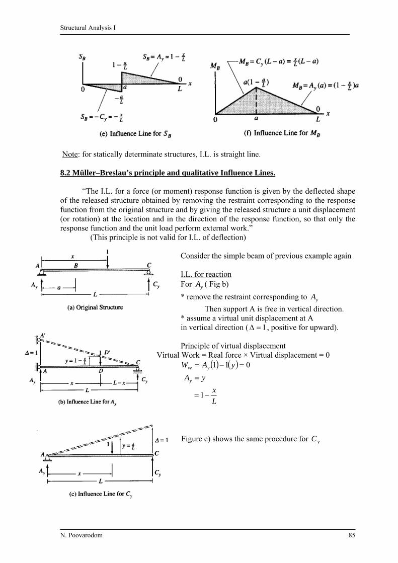
Structural Analysis I
N. Poovarodom 85
Note: for statically determinate structures, I.L. is straight line. 8.2 Müller–Breslau’s principle and qualitative Influence Lines. “The I.L. for a force (or moment) response function is given by the deflected shape of the released structure obtained by removing the restraint corresponding to the response function from the original structure and by giving the released structure a unit displacement (or rotation) at the location and in the direction of the response function, so that only the response function and the unit load perform external work.” (This principle is not valid for I.L. of deflection) Consider the simple beam of previous example again I.L. for reaction For yA ( Fig b)
* remove the restraint corresponding to yA
Then support A is free in vertical direction. * assume a virtual unit displacement at A in vertical direction ( 1 , positive for upward). Principle of virtual displacement Virtual Work = Real force × Virtual displacement = 0 011 yAW yve
yAy
L
x 1
Figure c) shows the same procedure for yC

Structural Analysis I
N. Poovarodom 86
I.L. for BS
- remove the restraint of BS By cutting the beam at B - Displace B vertically 211
1 and 2 make 2 segments parallel
( no work done from BM )
0121 ySSW BBe
yS B
From Fig .L
a
L
a 1, 21
I.L. for BM
- remove the restraint of BM by inserting a hinge at B - rotate the portions AB and AC - introduce virtual rotation 1 by rotating AB by 1 , AC by 2
121
0121 yMMW BBve
yM B
From figure (e) L
a
L
a 21 ,1
L
aa 1
8.3 Influence line for Deflections = The variation of a deflection of a structure as a unit load moves across the structure. By placing a unit load successively at arbitrary points, then determine an expression for the vertical deflection, and plot the expression. More efficient method by “ Maxwell’s law of reciprocal deflection” From a; BXf = at B when the load at x
BXf = the ordinate at x of the I.L. for B
From b; XBf = at x when the load at B
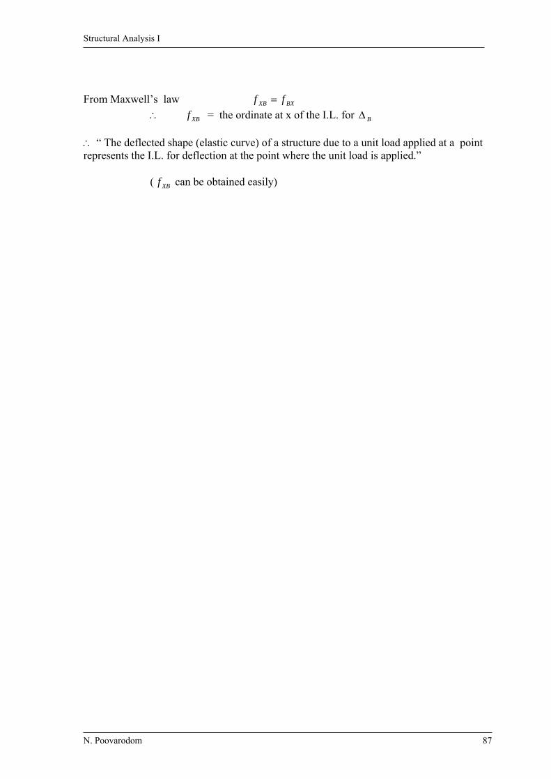
Structural Analysis I
N. Poovarodom 87
From Maxwell’s law BXXB ff
XBf = the ordinate at x of the I.L. for B “ The deflected shape (elastic curve) of a structure due to a unit load applied at a point represents the I.L. for deflection at the point where the unit load is applied.” ( XBf can be obtained easily)

Structural Analysis I
N. Poovarodom 88
Ex. 8.1 Draw Influence Line for Ay , Cy , SB and MB
a)
0CM 91 xAy
0AM 9xC y
Load is located at the left of B;
Consider the right FBD; SB = -Cy MB = Cy(6) Load is located at the right of B;
Consider the left FBD;
SB = Ay MB = Ay(3)
b)
0CM 81 xAy
0AM 8xC y
Load is located at the left of B;
Consider the right FBD; SB = -Cy MB = Cy(4) Load is located at the right of B;
Consider the left FBD; SB = +Ay MB = Ay(4)
-1.0
-0.25
-0.25
1.0 1.25
C
2m
2
0.5
-0.5
0.5
1/2 1.0
MB
4m 4m
B DA
SB
Cy
Ay
x
Ay Cy SB
MB 1
Ay Cy SB
MB 1
Ay Cy SB
MB 1
2
2/3
-1/3
1/3
2/3
1.0
1.0
MB
6m 3m
B CA
SB
Cy
Ay
x
Ay Cy SB
MB 1

Structural Analysis I
N. Poovarodom 89
Ex. 8.2 Draw Influence Line for SC, MC and shear just to the left, SD,L and just to the right SD,R of support D
123
4 xBy ,
123
1 xDy
Load at the left of C SC = -Dy
MC = Dy(8)
Load at the right of C SC = By MC = By(4) …………………………….. SD,L Load at the left of D
SD,L = -Dy Load at the right of D SD,L = By
…………………… SD,R
Load at the left of D SD,R = 0
Load at the right of D SD,R = 1
+1.0
-0.5-1.0
0.33
-2
2.67
-2.67
-0.5
0.67
-0.33
0.33
1.0
0.33
-0.33
0.671.0
1.33
1.5
-0.5
4m
E
6m8m 4m
C DA
By
Dy
SC
MC
SD,L
SD,R
B x
D
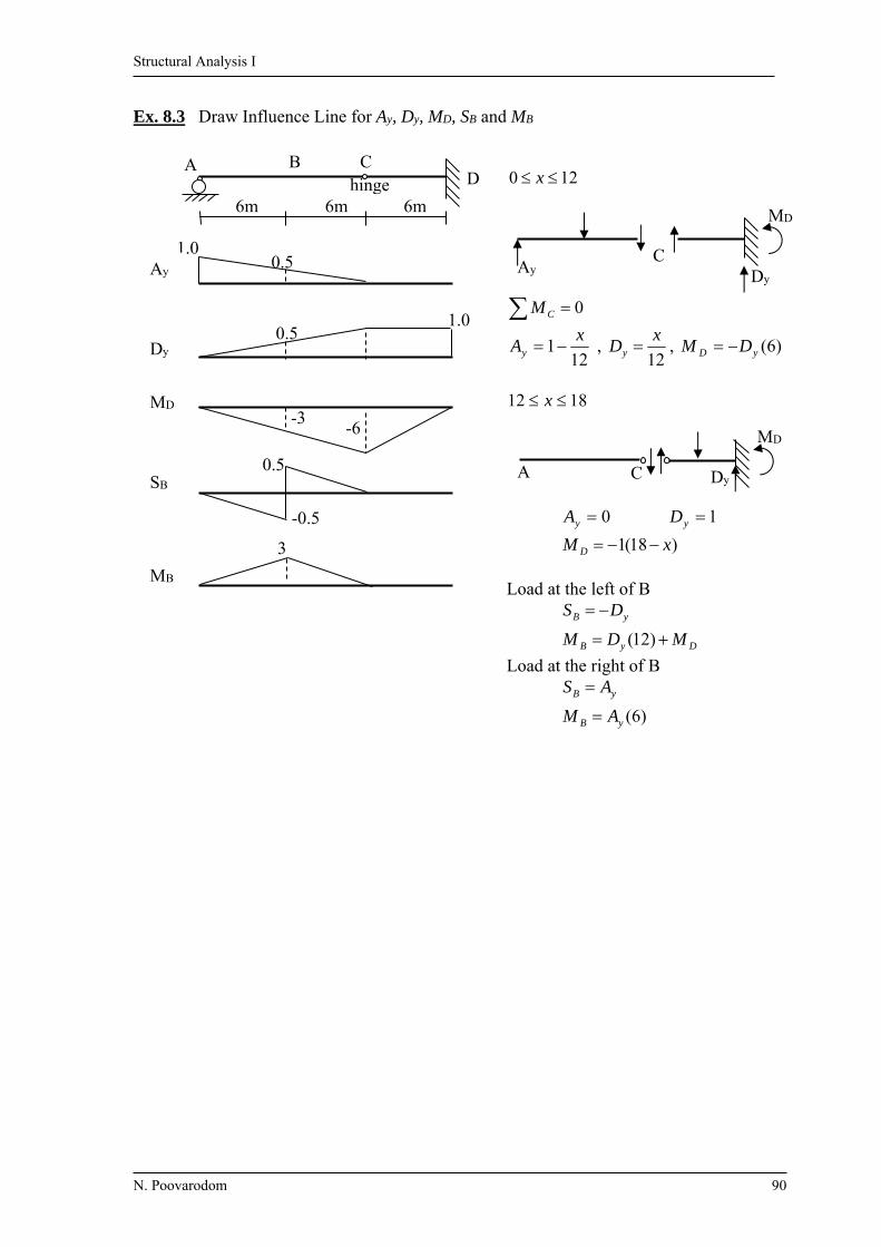
Structural Analysis I
N. Poovarodom 90
Ex. 8.3 Draw Influence Line for Ay, Dy, MD, SB and MB
120 x
0CM
121
xAy ,
12
xDy , )6(yD DM
1812 x
0yA 1yD
)18(1 xM D Load at the left of B
DyB
yB
MDM
DS
)12(
Load at the right of B
)6(yB
yB
AM
AS
3
-0.5
0.5
-6 -3
0.5 1.0
0.5
hinge D
6m
1.0
6m 6m
B A
Ay
Dy
MD
SB
MB
C
MD
Dy Ay
C
C
MD
A Dy

Structural Analysis I
N. Poovarodom 91
Ex. 8.4 Draw Influence Line for Ay , By , SE , ME
0BM , 1010
13 xAy
0AM , 10
3
xBy
Load at the left of E SE = - By ME = By(4) Load at the right of E SE = Ay ME = Ay(6)
-3.0
2.4
-1.2
-0.5 -0.6
0.4 0.3
-0.3
0.6 1
1.5
-0.5
0.4 1 1.3
6m 4m 5m 3m
7m 5m
E F G D C
B
A
Ay
By
SE
ME

Structural Analysis I
N. Poovarodom 92
Ex. 8.5 Draw Influence Line for Ay, MA, Ey, Gy, SC, MC, SF, and MF
+ MA
10’ 10’ 15’ 15’ 20’ 20’
G F E D C hinge hinge
B A
1
1
20
5/3
1
-2/3 1/2
-1/2
5
2/3 1/2
-1/2
7.5
-10
Ey
Gy
SC
MC
SF
MF
Ay
Ey
( =1, ccw)
MA
Ay
Released structure
1
1
1
Gy
SC 1
=1
1
=1

Structural Analysis I
N. Poovarodom 93
Ex. 8.6 Draw Influence Line for Ay, MA, Fy, MF, SB, MB, SE, and ME
-3
-1
-5
1
1 -6
10
1
C D E F B A
5 m 6 m 3 m 3 m 5 m
Ay
MA
MF
AF
SB
MB
SE
ME
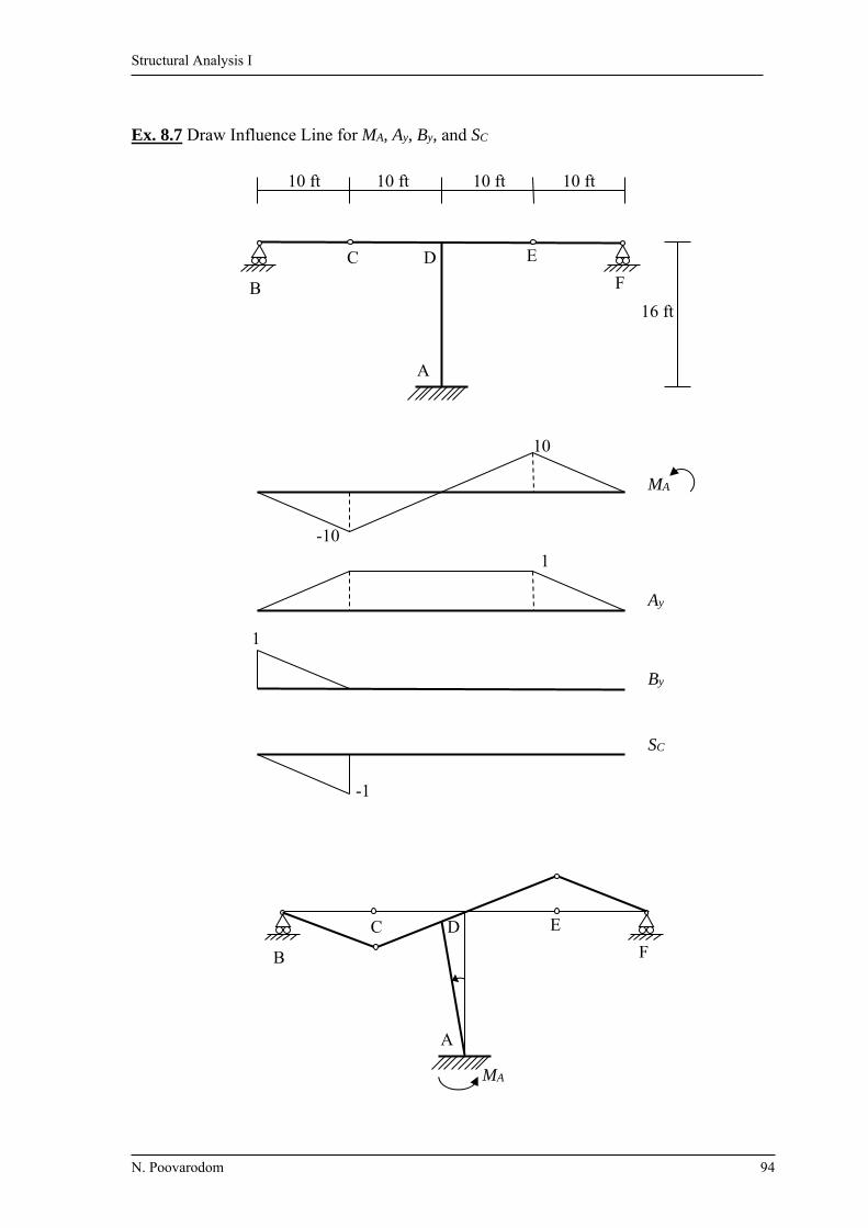
Structural Analysis I
N. Poovarodom 94
Ex. 8.7 Draw Influence Line for MA, Ay, By, and SC
-1
1
1
10
-10
10 ft 10 ft 10 ft 10 ft
16 ft
F
E D C
B
A
MA
Ay
By
SC
MA
F
E D C
B
A
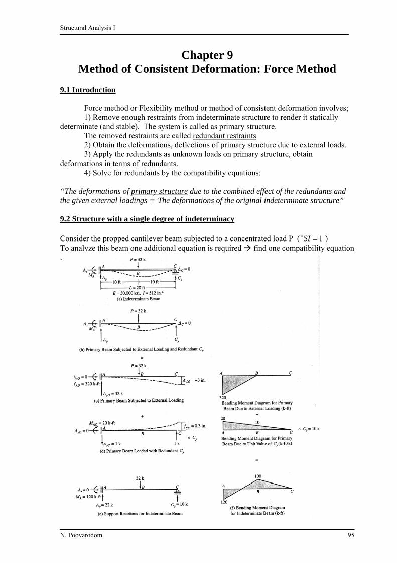
Structural Analysis I
N. Poovarodom 95
Chapter 9 Method of Consistent Deformation: Force Method
9.1 Introduction
Force method or Flexibility method or method of consistent deformation involves; 1) Remove enough restraints from indeterminate structure to render it statically determinate (and stable). The system is called as primary structure. The removed restraints are called redundant restraints 2) Obtain the deformations, deflections of primary structure due to external loads. 3) Apply the redundants as unknown loads on primary structure, obtain deformations in terms of redundants. 4) Solve for redundants by the compatibility equations: “The deformations of primary structure due to the combined effect of the redundants and the given external loadings The deformations of the original indeterminate structure” 9.2 Structure with a single degree of indeterminacy Consider the propped cantilever beam subjected to a concentrated load P ( 1SI ) To analyze this beam one additional equation is required find one compatibility equation .
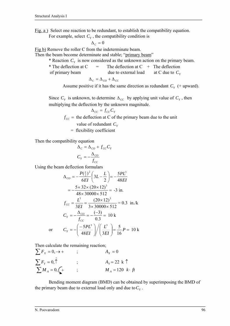
Structural Analysis I
N. Poovarodom 96
Fig. a ) Select one reaction to be redundant, to establish the compatibility equation. For example, select YC , the compatibility condition is
0C
Fig b) Remove the roller C from the indeterminate beam. Then the beam become determinate and stable; “primary beam”
* Reaction YC is now considered as the unknown action on the primary beam. * The deflection at C = The deflection at C + The deflection of primary beam due to external load at C due to YC
CCCOC
Assume positive if it has the same direction as redundant YC (+ upward). Since YC is unknown, to determine CC by applying unit value of YC , then
multiplying the deflection by the unknown magnitude. YCCCC Cf
CCf the deflection at C of the primary beam due to the unit
value of redundant YC = flexibility coefficient Then the compatibility equation YCCCOC Cf
CC
COY f
C
Using the beam deflection formulars
EI
PLLL
EI
P L
CO 48
5
23
6
)( 322
5123000048
)1220(325 3
-3 in.
512300003
)1220(
3
33
EI
LfCC = 0.3 in./k
3.0
)3(
CC
COY f
C 10 k
or
P
EI
L
EI
PLCY 16
5
348
5 33
10 k
Then calculate the remaining reaction;
,0XF ; 0XA
,0YF ; 22YA k
,0 AM ; 120AM ftk
Bending moment diagram (BMD) can be obtained by superimposing the BMD of the primary beam due to external load only and due to YC .
+
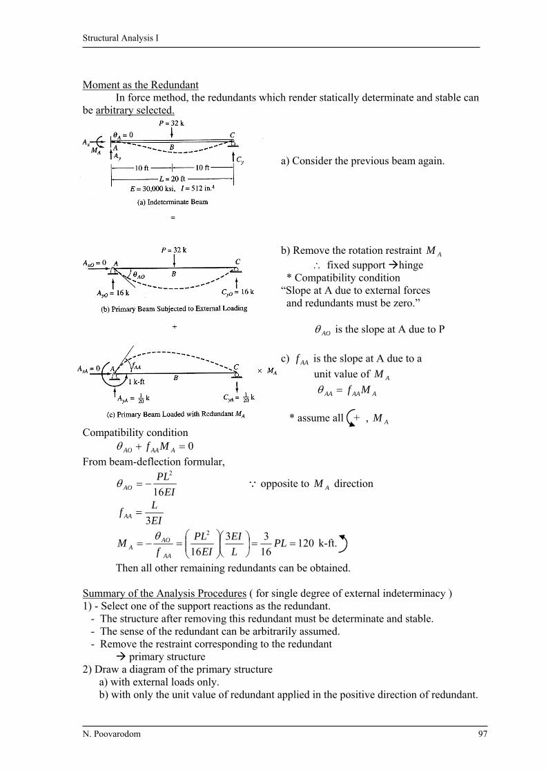
Structural Analysis I
N. Poovarodom 97
Moment as the Redundant In force method, the redundants which render statically determinate and stable can be arbitrary selected. a) Consider the previous beam again. b) Remove the rotation restraint AM fixed support hinge * Compatibility condition “Slope at A due to external forces and redundants must be zero.”
AO is the slope at A due to P
c) AAf is the slope at A due to a
unit value of AM
AAAAA Mf
* assume all , AM Compatibility condition 0 AAAAO Mf
From beam-deflection formular,
EI
PLAO 16
2
opposite to AM direction
EI
Lf AA 3
12016
33
16
2
PL
L
EI
EI
PL
fM
AA
AOA
k-ft.
Then all other remaining redundants can be obtained. Summary of the Analysis Procedures ( for single degree of external indeterminacy ) 1) - Select one of the support reactions as the redundant. - The structure after removing this redundant must be determinate and stable. - The sense of the redundant can be arbitrarily assumed. - Remove the restraint corresponding to the redundant primary structure 2) Draw a diagram of the primary structure
a) with external loads only. b) with only the unit value of redundant applied in the positive direction of redundant.
+

Structural Analysis I
N. Poovarodom 98
3) Write the compatibility equation in terms of the deflection of primary structure in 2a) and 2b).
4) Compute the deflection of the primary structure in 2a) and 2b). 5) Solve the compatibility equation for the unknown redundant. 6) Determine the remaining support reactions and draw SFD and BMD. 9.3 Internal Forces and Moments as redundants Choices of redundant are arbitrary, select the redundant in such the way that the analysis is simple. Consider a beam with 1SI , select BM as the redundant .
a) the slope of the elastic curve is continuous at B
b) remove restraint of rotation at B, point B becomes hinge. Then, a discontinuity at B is the change of slope between left and right of B due to external load
BRBLBOrel
c) Apply a unit value of BM by a pair of equal but opposite couples flexibility coefficient BBrelf
BBrelf = the change of slope between the tangents to the elastic curve at left and
right of B due to a unit value of BM .
= BBRBBL ff Now the continuous 2 span beam becomes 2 simple support beams and the elastic deflection can be computed easily.
EIEIEIBL
420)1420(
206
1410)620(
206
610 2222
EIEIBR
3.533)1030(
306
1012 22
EIEIBOrel
3.9533.533420
10 10
6 8 6
BL
12
20 10 BR

Structural Analysis I
N. Poovarodom 99
Flexibility coefficient;
EIf BBL 3
20
EI
f BBR
10
EIEI
f BBrel
67.16)10
3
20(
1
Then solving the compatibility equation, 0 BBBrelBOrel Mf
067.163.953
BMEIEI
BM = -57.19 k-ft (opposite to assumption) Then the other support reactions and SFD and BMD can be determined. Internally indeterminate Structures If structure is internally indeterminate but externally determinate then the redundants must be internal forces. Consider a truss with internal indeterminacy )]32([)3( jmrSI ( jrm 2)( ) 110)]342(6[)33( Select the axial force in AD to be the redundant ( ADF ).
The restraint corresponding to ADF is then removed from the truss by cutting member AD as in Fig (b). There exists a gap ADO in member AD.
Then the redundant force ADF must close the gap.
To evaluate the effect of ADF and its magnitude, apply the equal and opposite unit axial loads to member AD. ADF causes the ends of member AD to overlap by ADADf ,
The compatibility equation; 0, ADADADADO Ff
1 1
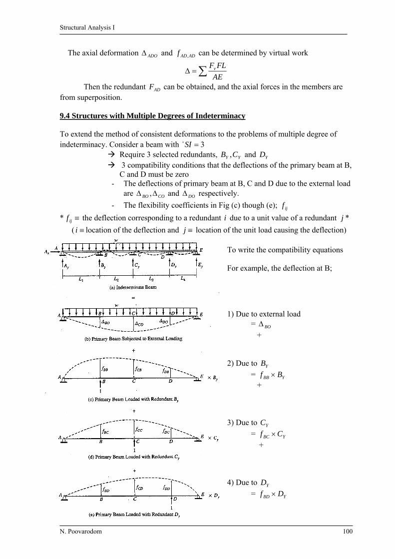
Structural Analysis I
N. Poovarodom 100
The axial deformation ADO and ADADf , can be determined by virtual work
AE
FLFv
Then the redundant ADF can be obtained, and the axial forces in the members are from superposition. 9.4 Structures with Multiple Degrees of Indeterminacy To extend the method of consistent deformations to the problems of multiple degree of indeterminacy. Consider a beam with 3SI
Require 3 selected redundants, YY CB , and YD 3 compatibility conditions that the deflections of the primary beam at B,
C and D must be zero - The deflections of primary beam at B, C and D due to the external load
are COBO , and DO respectively.
- The flexibility coefficients in Fig (c) though (e); ijf
* ijf the deflection corresponding to a redundant i due to a unit value of a redundant j *
( i location of the deflection and j location of the unit load causing the deflection) To write the compatibility equations
For example, the deflection at B; 1) Due to external load = BO
+ 2) Due to YB
= YBB Bf + 3) Due to YC
= YBC Cf
+ 4) Due to YD
= YBD Df
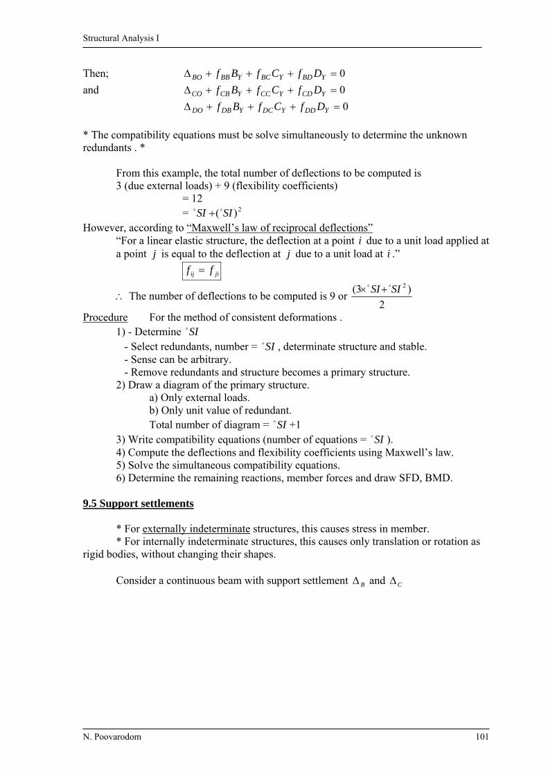
Structural Analysis I
N. Poovarodom 101
Then; 0 YBDYBCYBBBO DfCfBf
and 0 YCDYCCYCBCO DfCfBf
0 YDDYDCYDBDO DfCfBf
* The compatibility equations must be solve simultaneously to determine the unknown redundants . * From this example, the total number of deflections to be computed is
3 (due external loads) + 9 (flexibility coefficients) = 12 = 2)( SISI However, according to “Maxwell’s law of reciprocal deflections”
“For a linear elastic structure, the deflection at a point i due to a unit load applied at a point j is equal to the deflection at j due to a unit load at i .”
jiij ff
The number of deflections to be computed is 9 or 2
)3( 2SISI
Procedure For the method of consistent deformations . 1) - Determine SI - Select redundants, number = SI , determinate structure and stable. - Sense can be arbitrary. - Remove redundants and structure becomes a primary structure. 2) Draw a diagram of the primary structure. a) Only external loads. b) Only unit value of redundant. Total number of diagram = SI +1 3) Write compatibility equations (number of equations = SI ). 4) Compute the deflections and flexibility coefficients using Maxwell’s law. 5) Solve the simultaneous compatibility equations. 6) Determine the remaining reactions, member forces and draw SFD, BMD. 9.5 Support settlements * For externally indeterminate structures, this causes stress in member. * For internally indeterminate structures, this causes only translation or rotation as rigid bodies, without changing their shapes. Consider a continuous beam with support settlement B and C
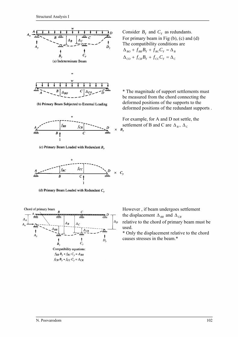
Structural Analysis I
N. Poovarodom 102
Consider YB and YC as redundants. For primary beam in Fig (b), (c) and (d) The compatibility conditions are
CYCCYCBCO
BYBCYBBBO
CfBf
CfBf
* The magnitude of support settlements must
be measured from the chord connecting the deformed positions of the supports to the deformed positions of the redundant supports . For example, for A and D not settle, the settlement of B and C are B , C
However , if beam undergoes settlement the displacement BR and CR
relative to the chord of primary beam must be used. * Only the displacement relative to the chord causes stresses in the beam.*

Structural Analysis I
N. Poovarodom 103
9.6 Temperature change and Fabrication Errors Temperature change and Fabrication errors may affect the stress conditions of externally and/or internally indeterminate structures. 9.7 Method of Least Work Consider a statically indeterminate beam Suppose select YB as the unknown redundant, the strain energy of this beam is a function of
external load w and redundant YB
),( YBwfU
Castigliano’s second theorem: “The partial derivative of the strain energy with respect to a force is equal tothe deflection of the point of application of the force along its line of action.”
at B , 0 BO we can write the compatibility equation as;
0
YB
U
minimum of the strain energy “The principle of Least Work” “The magnitudes of the redundants of a statically indeterminate structure must be such that the strain energy stored in the structure is minimum (internal work done is the least).” For multiple degree of indeterminacy, n redundants 1R , ….. nR
),.......,,,( 21 nRRRwfU
Apply the principle of least work separately for each iR
0
0
0
2
1
nR
U
R
U
R
U
Simultaneous equations of compatibility.
Note this principle cannot be used in problems of temperature change, support settlement or fabrication error.
A B C
W
By

Structural Analysis I
N. Poovarodom 104
Ex. 9.1 Determine the reactions and draw the SFD and BMD of the beam shown. Select the reaction at the roller to be the redundant.
EI = Constant
Soln 1) Select Dy as the redundant 2) 3) The compatibility equation, at D 0 yDDDO Df
4) Using the beam-deflection formulas
EI
Lf
EIEI
L
LLEI
LLL
EI
L
DD
DO
DO
3
54
742500
54
220
3236
321533
6
330
3
3
22
5)
k
L
EI
EI
L
fD
DD
DOy 22.12
3
54
2203
3
6)
MA
DyAy
Ax
DCBA5 ft 5 ft 5 ft
15 k 30 k
DO
15 30
(a)
DDf
1 (b)
-116.7
47.261.1
-12.22
2.7832.78
116.7 k.ft
12.22k32.78k
1530Reaction
SFD
BMD

Structural Analysis I
N. Poovarodom 105
Ex. 9.2 Determine the reactions and draw the SFD and BMD of the beam shown. Select the moment at support as redundant.
Soln 1) Select MC as the redundant 2)
3) 0 CCCCO Mf
4) EIEIEIEI
PL
EI
MLCO
1230
16
)12)(120(
6
)12)(75(
166
22
(opposite to MC)
EIEI
LfCC
4
3
5) mkNf
MCC
COC .5.307
4
1230
6)
MC
Cx 120kN
Cy Ay
75kN.m
C
6m6m
B
A
CO 12075
(a)
CCf 1
(b)
-307.5
243.875
-91.87
28.13
307.5
28.13
75120
91.87
Reaction
SFD
BMD

Structural Analysis I
N. Poovarodom 106
Ex. 9.3 Determine the reactions and draw the SFD and BMD of the beam shown. Select the reaction at central support as redundant.
E = Constant
Solution 1) Select By as the redundant 2) Determine BO and fBB by Virtual Force Principle
3)
Segment Origin Limit EI M Mv
AB A 0-10 EI 2
15165
2xx x
2
1
BC D 5-10 2EI 2
15)5(60195
2xxx x
2
1
CD D 0-5 2EI 2
15195
2xx x
2
1
BO dxxx
xEI
dxEI
MM v
2
1
2
15165
1 10
0
2
5
0
210
5 2
1
2
15195
2
1
2
15)5(60195
2
1dxx
xxdxx
xxx
EI
EI
28125
fBB
dxxdxx
EIdx
EI
MM v
v
210
0
210
0 2
1
2
1
2
11
EI
125
4) By = BB
O
fB =
125
28125 EI
EI kN225
Dy By Ay
Ax D
C
B (2I)
(I)
60 kN15 kN/m
5 m5 m10 m
A
xx
B
195165
DC
6015
A
Actual system
M-system 1/21/2
1 D
Virtual system
Mv-system

Structural Analysis I
N. Poovarodom 107
5)
-7.5
52.5
-97.5
127.5
52.5
-82.5
91.88
225
-225
225 82.552.5
D
6015
A
3.5 m
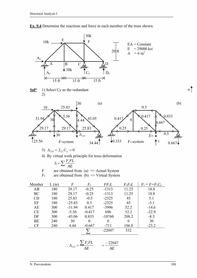
Structural Analysis I
N. Poovarodom 108
Ex. 9.4 Determine the reactions and force in each member of the truss shown. EA = Constant E = 29000 ksi A = 6 in2
Soln 1) Select Cy as the redundant 2)
3) 0 yCCCO Cf
4) By virtual work principle for truss deformation
AE
FLFv
F are obtained from (a) => Actual System Fv are obtained from (b) => Virtual System Member L (in) F Fv FFvL FvFvL Fi = F+FvCy
AB 180 29.17 -0.25 -1313 11.25 18.8 BC 180 29.17 -0.25 -1313 11.25 18.8 CD 180 25.83 -0.5 -2325 45 5.1 EF 180 -25.83 0.5 -2325 45 -5.1 AE 300 -31.94 0.417 -3996 52.2 -14.6 CE 300 -5.56 -0.417 696 52.2 -22.9 DF 300 -43.06 0.833 -10760 208.2 -8.5 BE 240 30 0 0 0 30 CF 240 4.44 -0.667 -711 106.8 -23.2
-22047 532
AE
FLFvCO
AE
22047
20 ft
30k
10k
Ax
Ay Cy Dy
D C B A
E F
15 ft 15 ft 15 ft
30k
10 30
34.44
43.05 31.94 5.56
30 4.44
29.17 25.83 29.17
25.56
25.83
30 CO
(a)
F-system
fCC
0.667
0.833 0.417
0.417 0
0.667
0.25
0.5 0.25
0.333
0.5
1
(b)
Fv-system

Structural Analysis I
N. Poovarodom 109
AE
LFFf vv
CC
AE
532
CC
COy f
C
532
)22047(
kC y 5.41
Reactions can be obtained by equilibrium of the system; Ay = 11.7 k , Ax = 10 k , Dy = 6.8 k Member axial forces are obtained by superposition Fig. (a) + Fig. (b) Cy Fi = F+FvCy
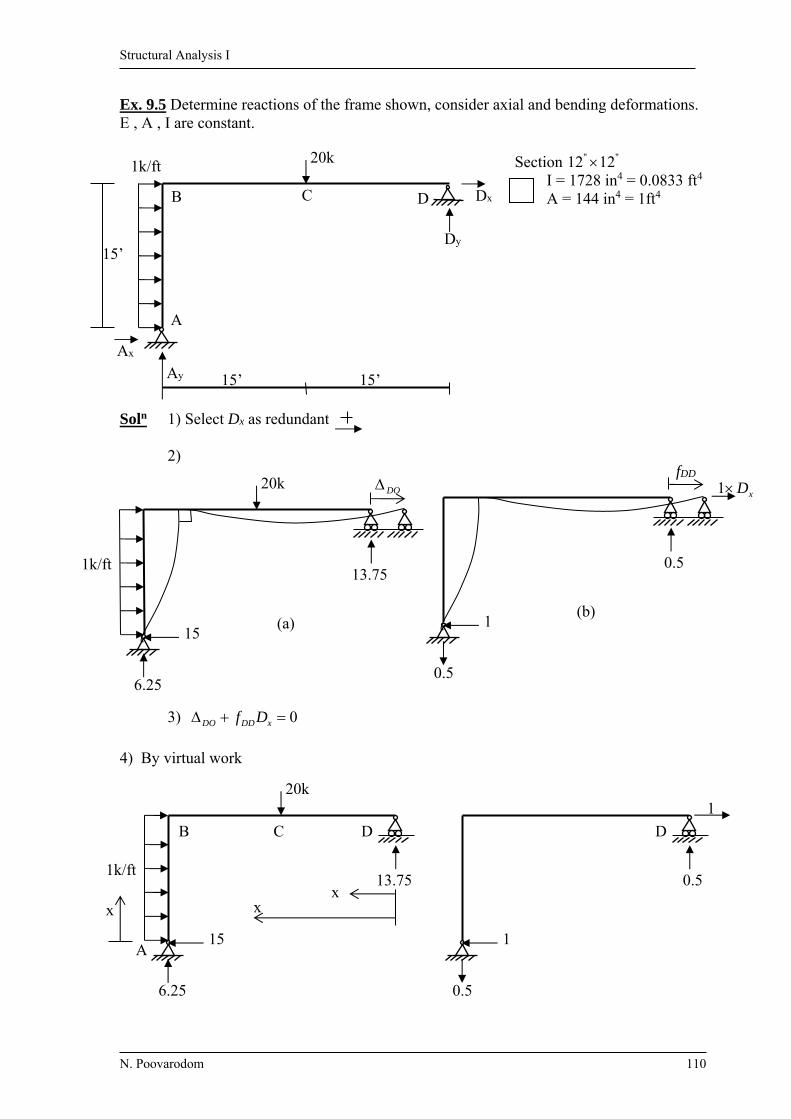
Structural Analysis I
N. Poovarodom 110
Ex. 9.5 Determine reactions of the frame shown, consider axial and bending deformations. E , A , I are constant.
Section "" 1212
I = 1728 in4 = 0.0833 ft4 A = 144 in4 = 1ft4
Soln 1) Select Dx as redundant 2)
3) 0 xDDDO Df
4) By virtual work
15’
1k/ft
C
20k
15’ 15’ Ay
Ax
A
B
Dy
D Dx
DO
13.75
6.25
15
1k/ft
20k
(a)
xD1 fDD
0.5
0.5
1 (b)
x x
x
D C B
A
13.75
6.25
15
1k/ft
20k 1
D
0.5
0.5
1

Structural Analysis I
N. Poovarodom 111
Segment Origin Limit M Mv F Fv
AB A 0-15 2
152x
x x -6.25 0.5
BC D 15-30 13.75x-20(x-15) 0.5x 0 1 CD D 0-15 13.75x 0.5x 0 1
15
0
30
15
15
0
2
)5.0)(75.13()5.0))(15(2075.13()(2
151
dxxxdxxxxdxxx
xEI
EA
FLFdx
EI
MM vvDO
EEEEAEI
dxEA
5317309.465317779.4644297
)5.0)(25.6(1 15
0
301155.01
)5.0(1 22
15
0
30
0
22
EAdxxdxx
EI
EA
LFFdx
EI
MMf v
vv
vDD
EEEEAEI
4055475.334052075.333375
5) kf
DDD
DOx 11.13
kDx 11.13
If not consider axial deformation; kDx 125.13
Other reactions are obtained by superposition Reactions = Fig (a) + Fig (b) Dx
1.9
12.8
7.2
13.1

Structural Analysis I
N. Poovarodom 112
Ex. 9.6 Repeat Ex. 9.3, by selecting MB as the redundant.
Solution 1) Select MB, remove restraint (internal moment at B) 2)
3) BBRBBLBBrel
BRBLBOrel
fff
0 BBBrelBOrel Mf
4) By deflection formula, assume the direction of to be the same as redundant.
EIIEIE
EIEIEI
wL
BR
BL
500
)2(16
10160
)2(24
1015
625
24
1015
2423
33
EIEIBOrel
1125500625
)2(3
103
10
IEf
EIf
BBR
BBL
EIEI
fBBrel
5
3
15
mkNM B 2255
1125 (The same result as in Ex. 9.3)
BR BL 2I I
60 15
BM1
BBRf BBLf
BR BL
BL BOrel
BBRf BBLf
BBLf BBrelf
Dy By Ay
Ax D
C
B (2I)
(I)
60 kN15 kN/m
5 m5 m10 m
A
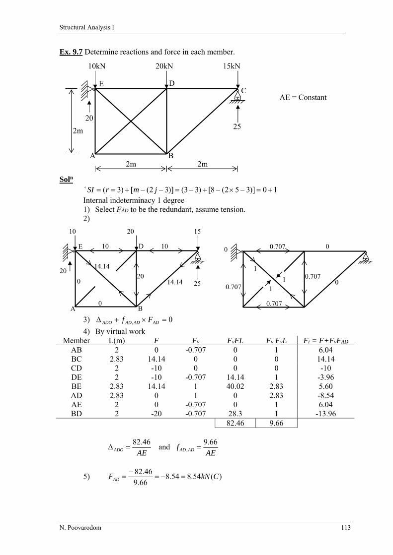
Structural Analysis I
N. Poovarodom 113
Ex. 9.7 Determine reactions and force in each member. AE = Constant
Soln 10)]352(8[)33()]32([)3( jmrSI Internal indeterminacy 1 degree
1) Select FAD to be the redundant, assume tension. 2)
3) 0, ADADADADO Ff
4) By virtual work Member L(m) F Fv FvFL Fv FvL Fi = F+FvFAD
AB 2 0 -0.707 0 1 6.04 BC 2.83 14.14 0 0 0 14.14 CD 2 -10 0 0 0 -10 DE 2 -10 -0.707 14.14 1 -3.96 BE 2.83 14.14 1 40.02 2.83 5.60 AD 2.83 0 1 0 2.83 -8.54 AE 2 0 -0.707 0 1 6.04 BD 2 -20 -0.707 28.3 1 -13.96
82.46 9.66
46.82
AEADO and AE
f ADAD
66.9 ,
5) )(54.854.866.9
46.82CkNFAD
C
2m
2m2m
25
15kN20kN10kN
20
E D
BA
0
14.14
14.140
10 10
20 25
1520 10
20
E D
B A
0
11
0.707
1
00.707
0.707
0.707
0

Structural Analysis I
N. Poovarodom 114
If select FAB as a redundant;
Member L(m) Fa Fb Fa FbL Fb2L
AE 2 0 1 0 2 AD 2.83 0 -1.414 0 5.66 BE 2.83 14.14 -1.414 -56.62 5.66 BD 2 -20 1 -40 2 BC 2.83 14.14 0 0 0 ED 2 -10 1 -20 2 DC 2 -10 0 0 0 AB 2 0 1 0 2
-116.62 19.32
)(04.632.19
)62.116(TkNFAB
20 15
0 10
(a) 1
0
(b)
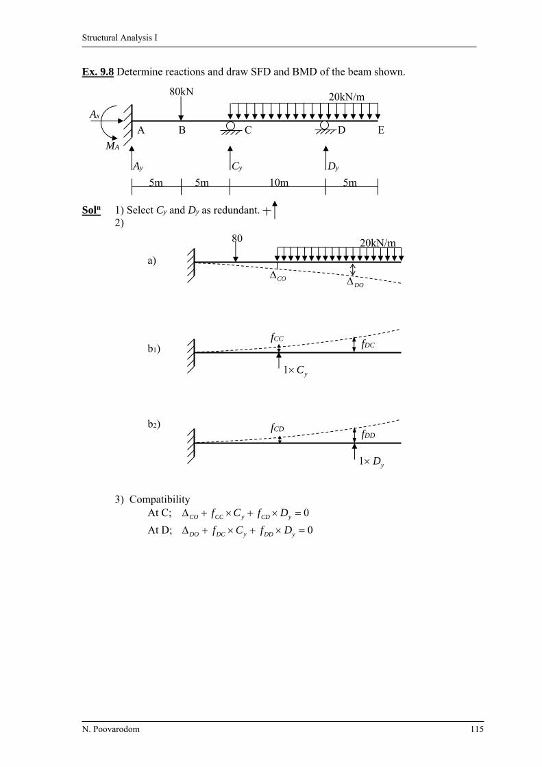
Structural Analysis I
N. Poovarodom 115
Ex. 9.8 Determine reactions and draw SFD and BMD of the beam shown.
Soln 1) Select Cy and Dy as redundant. 2) a) b1) b2) 3) Compatibility At C; 0 yCDyCCCO DfCf
At D; 0 yDDyDCDO DfCf
5m 5m 10m 5m
Ay Cy Dy
MA
Ax
20kN/m 80kN
E D C B A
DO CO
20kN/m 80
yC1
fDC fCC
fDD fCD
yD1

Structural Analysis I
N. Poovarodom 116
4) Consider formula for calculation of deflection
calculate deflection y(x)
4223 6424
xxLLxEI
wy
+
xaEI
way
xxaaxEI
wy
424
6424
3
4223
Lxa
ax
0
xaaxxLLxEI
w
xaLxaLEI
w
y344223
2223
46424
)(6)(424
Lxa
ax
0
10356
58010410101025610254
24
20 2444223
EIEICO
EI
220833
20356
5802010410202025610254
24
20 2344223
EIEIDO
EI
676667
EIEI
xaEI
PafCC
3.333)3010(
6
10)3(
6
22
EIEI
f DD
7.2666)20320(
6
202
a
L
x
w
w
w

Structural Analysis I
N. Poovarodom 117
EIEI
axxEI
PfCD
3.833
6
)1020310()3(
6
2323
EIEIEI
xaPaf DC
3.833
6
)20310(10
6
)3( 22
5) From compatibility equations,
07.26663.8336766671
03.8333.3332208331
yy
yy
DCEI
DCEI
Cy = 128.7 kN Dy = 213.5 kN
DCCD ff
-250
72
-115
96
-93
4.325 113.5
100
37.8
-42.2
86.5
37.8 128.7 213.5
93
20 80
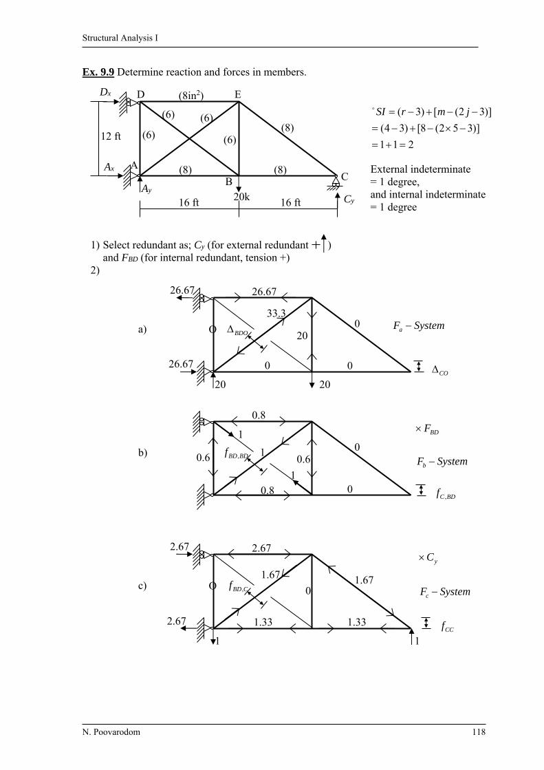
Structural Analysis I
N. Poovarodom 118
Ex. 9.9 Determine reaction and forces in members.
211
)]352(8[)34(
)]32([)3(
jmrSI
External indeterminate = 1 degree, and internal indeterminate = 1 degree
1) Select redundant as; Cy (for external redundant ) and FBD (for internal redundant, tension +) 2)
(6)
(6) (6)
(6)
(8in2)
(8) (8)
(8)
16 ft 16 ft Cy 20k Ay
12 ft
Ax
Dx E D
C B
A
26.67
O
33.3
20
26.67
0
0
20
26.67
a)
0
20
SystemFa BDO
CO
1
1
0.8
0.6 1 0.6
0.8
0
0 b) SystemF
F
b
BD
BDBDf ,
BDCf ,
2.67
1
1.33
O 1.67
0
2.67
1.33
1.67
1
2.67
c) SystemF
C
c
y
CBDf ,
CCf

Structural Analysis I
N. Poovarodom 119
3) Compatibility equations; At BD; 0,, yCBDBDBDBDBDO CfFf
At C; 0, yCCBDBDCCO CfFf
4)
Member L
(in) A
(in2) Fa
(k) Fb Fc Fa FbL/A Fa FcL/A Fb
2L/A Fc2L/A Fb FcL/A
F=Fa+ FbFBD+ FcCy
AB 192 8 0 -0.8 1.33 0 0 15.36 42.45 -25.54 -1.44 BC 192 8 0 0 1.33 0 0 0 42.45 0 8.29 DE 192 8 26.7 -0.8 -2.67 -512 -1709 15.36 171.1 51.26 0.31 AD 144 6 0 -0.6 0 0 0 8.64 0 0 -7.3 BE 144 6 20 -0.6 0 -288 0 8.64 0 0 12.7 AE 240 6 -33.3 1 1.67 -1333 -2226 40 111.56 66.8 -10.77 CE 240 8 0 0 -1.67 0 0 0 83.67 0 -10.4 BD 240 6 0 1 0 0 0 40 0 0 12.16
-2133 -3935 128 451.2 92.52
EAE
LFF baBDO
2133 ,
EAE
LFF caCO
3935 ,
EAE
LFf b
BDBD
1282
, , EAE
LFf c
CC
2.4512
EAE
LFFff cb
BDCCBD
52.92,,
6) Solve for FBD , Cy FBD = 12.16 k (T) , Cy = 6.23 k Other reactions and member forces can be obtained; Ax = 10.04 k , Ay = 13.77 k , Dx = 10.04 k

Structural Analysis I
N. Poovarodom 120
Ex. 9.10 Determine reactions of the frame shown by considering effect of bending deformation only, EI = constant. Solution
1) Select Cy , Dy as redundant
2)
10 ft 10 ft
15 ft
2.5 k/ft
MA
Ay
Ax
Cy Dy
DB
A
C
50 k-ft
DO CO 50
x
x
x2.5
37.5 231.25
Ma - System
1
1
DCf CCf
10
Mb - System
1
1
DDf CDf
20
Mc - System

Structural Analysis I
N. Poovarodom 121
3) Compatibility equations; At C; 0 yCDyCCCO DfCf
At D; 0 yDDyDCDO DfCf
Segment Origin Limit Ma Mb Mc
AB A 0-15 25.23125.25.37 2 xx 10 20 BC D 10-20 50 x-10 x CD D 0-10 50 0 x
CO = dxEI
MM ba
=
15
0
20
10
2
)10(501025.2312
5.25.37
1dxxdx
xx
EI
= EI
5.4062
DO = dxEI
MM ca
=
15
0
20
0
2
502025.2312
5.25.37
1xdxdx
xx
EI
= EI
3125
CCf = dxEI
MM bb
=
15
0
20
10
2)10(1001
dxxdxEI
= EI
3.1833
DDf = dxEI
MM cc
=
15
0
20
0
22201
dxxdxEI
= EI
7.8666
CDf = DCf = dxEI
MM cb
=
15
0
20
10
)10(2001
xdxxdxEI
= EI
3.3833
4) Solve compatibility equations; kC y 45.19 , kkDy 24.824.8

Structural Analysis I
N. Poovarodom 122
Ex. 9.11 Determine reactions for the beam due to a small downward settlement at C E = constant
1) Select Cy as a redundant 2) (no external force , CO =0)
3) 0+fCCCy = -
4) L
L
L
CC dxxEI
dxxEI
f2
22
0
2
2
11
EI
L3
16
3
5)
33
16
L
EIC y
33
16
L
EI
x x
(I)(2I)
L/2L/2
CB A
1
CCf
23
16
L
EI
33
16
L
EI
33
16
L
EI
Reaction
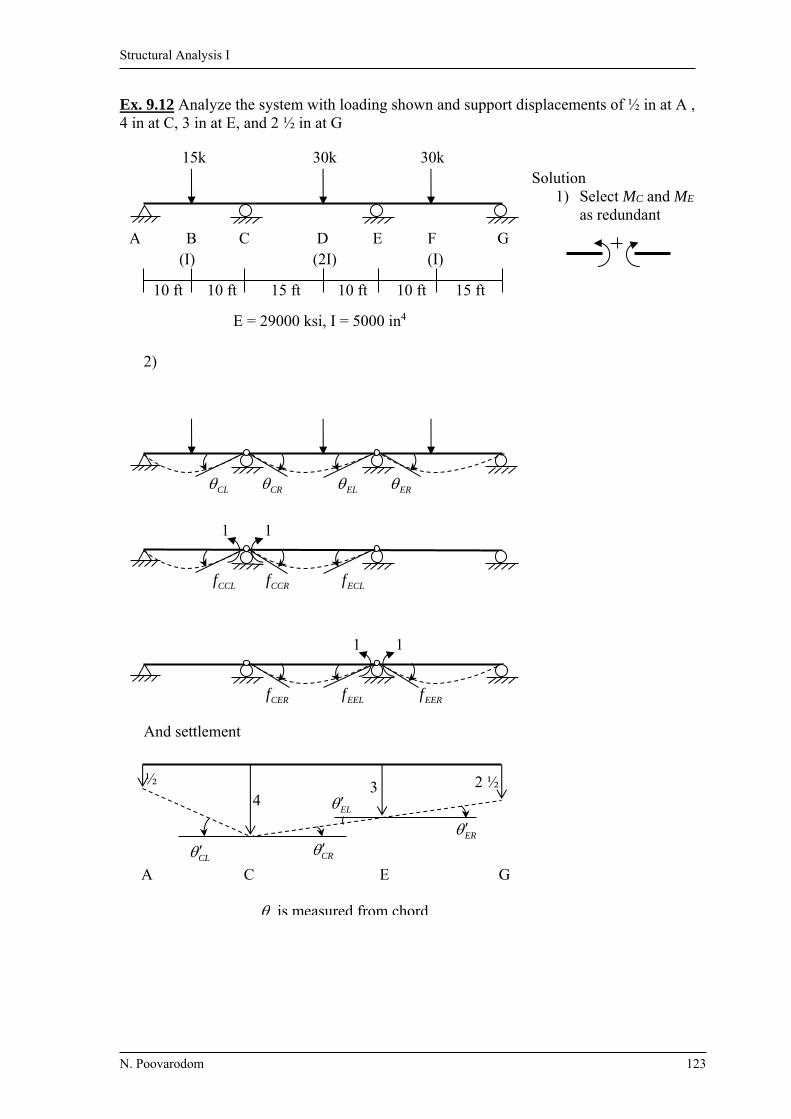
Structural Analysis I
N. Poovarodom 123
Ex. 9.12 Analyze the system with loading shown and support displacements of ½ in at A , 4 in at C, 3 in at E, and 2 ½ in at G
Solution
1) Select MC and ME as redundant
2)
And settlement
30k 30k 15k
(I) (2I) (I)
15 ft 10 ft 10 ft 15 ft 10 ft 10 ft
G F E C A B D
E = 29000 ksi, I = 5000 in4
ER EL CR CL
1 1
ECLf CCRf CCLf
EERf
1 1
EELf CERf
CL
2 ½ 3 4
½
A C E G
is measured from chord
CR ER
EL

Structural Analysis I
N. Poovarodom 124
3) Compatibility equations;
EEEErelCECEOrel
CECECCCrelCOrel
MfMf
MfMf
4) By Tables of Beam-Deflection formula;
EIEIff
EIEIf
EIEIf
EIEI
EIEI
ECCE
EErel
CCrel
EOrel
CRCLCOrel
08.2
26
25
5.12
3
25
23
251
83.10
23
25
3
201
18001525
256
15301525
256
1530
2
11
9001025
256
1030
2
1
16
20151
2222
222
From figure L
a
0146.01220
5.04
CL rad
00333.01225
34
CR rad
0179.0 CRCLC rad
00333.0300
43
EL rad
00167.0300
5.23
ER rad
00166.0 ERELE rad 5) Solving compatibility equation, EI = 29000 ksi 5000 in4 MC = 1682 k-ft ME = -559 k-ft
(For example, rad 0.000894 500029000
12900 2
COrel )
Then the reactions; Ay = 91.6 k Cy = 154.2 k Ey = 148 k Gy = 10.4 k
chord
is measured from chord
from settlement is also measured from chord
chord

Structural Analysis I
N. Poovarodom 125
Ex. 9.13 Determine reactions and force in each member E = 200 GPa A = 3000 mm2 = 15102.1 C
a) Due to a temperature drop of 25 C in AB, BC and CD and increase of 60 C in EF Solution 1) Select FBF as redundant (Tension as +) 2)
3) 0, BFBFBFBFO Ff
4) Virtual Work aBFO FLT
AE
LFf a
BFBF
2
,
Member L (m) T Fa TLFa Fa2L F=0+FaFBF (kN)
AB 8 -25 0 0 0 0 BC 8 -25 -0.8 160 5.12 -37.33 CD 8 -25 0 0 0 0 EF 8 +60 -0.8 -384 5.12 -37.33 BF 10 0 1.0 0 10 46.67 CE 10 0 1.0 0 10 46.67 BE 6 0 -0.6 0 2.16 -28.0 CF 6 0 -0.6 0 2.16 -28.0
-224 34.56 *AE and DF has zero axial force.
8 m8 m 8 m
6m
FE
DCB A
BFO
+60
-25 -25-25
BFBFf ,
11
10.6 0.6
0
00.8
0.8
0
0
Fa-System

Structural Analysis I
N. Poovarodom 126
m/kN 1076.5
300010200
100056.34
m 00269.0102.1224
56
2
,
5
BFBF
BFO
f
5) kN 7.46,
BFBF
BFOBF f
F (T)
b) If member EF is 30 mm too short
0
104.2)8.0(1000
30
,
2
BFBFBFBFO
aBFO
Ff
mFe
)(7.416
7.4161076.5
104.25
2
,
CkNF
kNf
F
BF
BFBF
BFOBF
Ex. 9.14 Analysis the beam shown by the method of least work
Soln Select By as redundant
0
2
1
0
2
L
yy
L
dxEI
M
B
M
B
U
dxEI
MU
Segment x-coordinate
M yBM
Origin Limit CB C 0-6 -100x 0
BA C 6-18 )6(2
)6(10100
2
xBx
x y x-6
0))6()6(5100)(6(18
6
2
dxxBxxxB
Uy
y
0576126720 yB
kNBy 220
(2I)(I) 6m12m
CB A
10kN/m 100kN
x By 220-By
2520-12By 100
x

Structural Analysis I
N. Poovarodom 127
Ex. 9.15 Determine the reactions and member forces by the method of least work. E = 29,000 ksi
Soln Select FBD as redundant. (Tension = +) Then to determine FBD by minimizing the strain energy with respect to FBD.
0
2
2
AE
FL
F
F
F
U
AE
LFU
BDBD
Member L (in)
A (in2)
F F/ FBD ( F/ FBD)(FL/A) (Sub. FBD) F
AB 192 8 -26.67-0.8 FBD -0.8 512+15.36 FBD -51.6 BC 192 8 -26.67 0 0 -26.7 DE 192 8 80-0.8 FBD -0.8 -1536+15.36 FBD 55.1 AD 144 6 -0.6 FBD -0.6 8.64 FBD -18.7 BE 144 6 20-0.6 FBD -0.6 -288+8.64 FBD 1.3 AE 240 6 -66.67+ FBD 1 -2667+40 FBD -35.6 CE 240 8 33.33 0 0 33.3 BD 240 6 FBD 1 40 FBD 31.1
-3979+128 FBD
01
A
FL
F
F
EF
U
BDBD
-3979+128 FBD = 0 FBD = 31.1 k (T)
(6)
(6) (6)
(6)
(8)
(8 in2) (8)
(8)
16 ft 16 ft 20k
20k
12 ft
E D
C B
A
66.67- FBD 20-0.6 FBD
80-0.8 FBD
26.67+0.8 FBD
FBD
FBD
0.6FBD
80
80
40
26.67
33.33
20 20
C

Structural Analysis I
N. Poovarodom 128
Ex. 9.16 Determine force in rod BC and BD of the system shown. A = 100 mm2 I = 200106 mm4 E = 200 GPa Consider only bending deformation in beam AB
Solution Select FBD and FBC as redundant. (Tension = +)
AE
FL
F
Fdx
EI
M
F
M
F
U
AE
LFdx
EI
MU
i
L
ii
AB
0
22
2
1
2
1
AB M = (FBC + 5
3FBD – 80)x
xF
M
BC
, xF
M
BD 5
3
BC F = FBC
1
BCF
F , 0
BDF
F
BD F = FBD
1
BDF
F , 0
BCF
F
0000,20
5
580
5
3
000,40
1
0000,20
3
380
5
3
000,40
1
005
380
5
31
00805
31
4
0
3
4
0
3
24
0
4
0
2
BDBDBC
BCBDBC
BDBDBDBC
BD
BCBCBDBC
BC
FxFF
FxFF
AE
LFdxxFF
EIF
U
AE
LFdxxFF
EIF
U
FBC = 53.43 kN (T) FBD = 19.23 kN (T)
80kN
3m
4m
(A)(A)
(I)
D C
B (hinge)
A
37
FBCFBD
x80
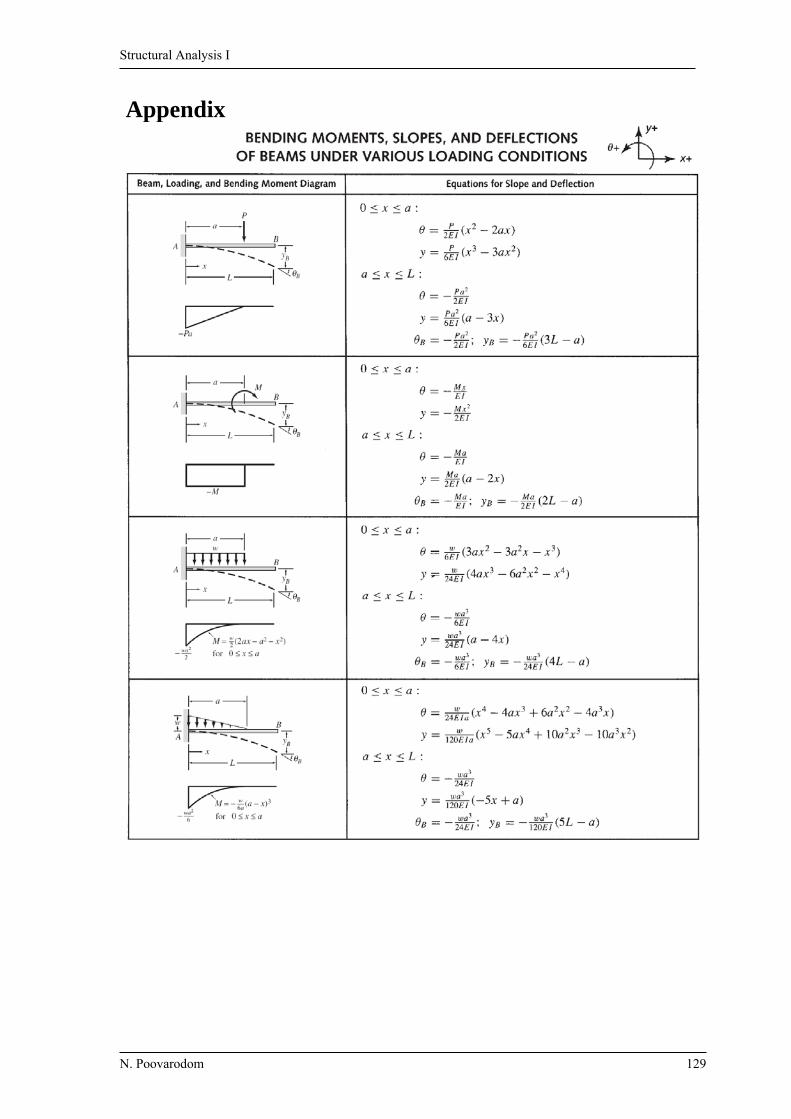
Structural Analysis I
N. Poovarodom 129
Appendix
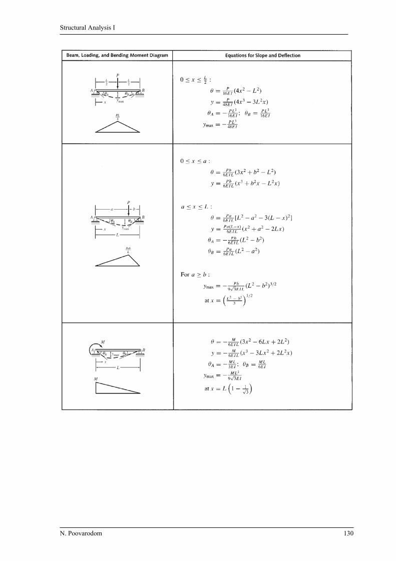
Structural Analysis I
N. Poovarodom 130
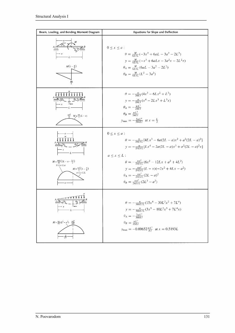
Structural Analysis I
N. Poovarodom 131

Structural Analysis I
N. Poovarodom 132