3g technologies 008 - tut technologies.pdf · • 3g technologies • wcdma ... full rate speech...
TRANSCRIPT

1 Magister Solutions 2006-11-02 / JKu
3G Technologies
WCDMA, TD-(S)CDMA and cdma2000Janne Kurjenniemi
2 Magister Solutions 2006-11-02 / JKu
Outline
• Background• Why new radio access• Frequency allocation• Spread spectrum
• 3G technologies• WCDMA
• Overview• Key features• Radio resource management
• TD-(S)CDMA• Overview of TD-CDMA and TD-SCDMA• Radio resource management
• cdma2000• Overview and differences to WCDMA

3 Magister Solutions 2006-11-02 / JKu
Why new Access system for UMTS
• Need for universal standard• Support for packet data services
• IP data in core network• IP radio access• Real time IP
• New services in mobile multimedia need flexible utilization of the spectrum (multiplexing, link adaptation)
• Using always the same radio is preferred
• FDMA and TDMA are not efficient enough: silent periods in speech will can not be utilized
• WCDMA was selected for a radio access system for UMTS (1997)
4 Magister Solutions 2006-11-02 / JKu
WCDMA Background
• WCDMA was studied in various research programs in the industry and universities
• The European proposal to ETSI was generated within ACTS FRAMES project
RACE II-ATDMA-CODIT
1988 1992 1998
ETSIDecision:-WCDMA forFDD operation
19971995
RACE I-basicstudies
ETSIConcept groups
ACTS/FRAMES-FMA1:WTDMA-FMA2:WCDMA
. . .

5 Magister Solutions 2006-11-02 / JKu
Background for 3GPP Creation
• WCDMA was chosen besides ETSI also in other forums like ARIB (Japan) as 3G technology late 1997/early 1998.
• During 1998 parallel work proceeded in ETSI and ARIB (mainly), with commonality but also differences
• Resource consuming for companies with global presence and not likely to arrive to identical specifications globally
• The same discussion e.g. in ETSI and ARIB sometimes ended up to different conclusions
• Work was also on-going in USA and Korea
6 Magister Solutions 2006-11-02 / JKu
Creation of 3GPP
• At end of 1998 different standardization organization got together and created 3GPP, 3rd Generation Partnership Project.
• 5 Founding members ETSI, ARIB+TTC (Japan), TTA (Korea) T1P1 (USA)• CWTS (China) joined later.
• Different companies are members through their respective standardization organization.
ETSI Members
ETSI
ARIB Members
ARIB
TTA Members
TTA
T1P1 Members
T1P1
TTC Members
TTC
CWTS Members
CWTS
3GPP

7 Magister Solutions 2006-11-02 / JKu
Evolution of Mobile Radio Standards
EDGE
GPRSGSM HSCSD
cdmaOne(IS-95)
WCDMA FDD HSDPA
cdma2000
TD-SCDMA TDD LCR
cdma20001XEV - DO
cdma20001XEV - DV
TD-CDMATDD HCR
TDD, TSM
HSDPA
8 Magister Solutions 2006-11-02 / JKu
Frequency allocations to UMTS
• Frequency plans of Europe, Japan and Korea are harmonized• US plan is incompatible, IMT-2000 spectrum used for the US 2G standards• IMT-2000 in Europe:
• FDD 2x60MHz • TDD 20MHz+15MHz
• Note: GSM band is close to the UMTS band in uplink (Interference)

9 Magister Solutions 2006-11-02 / JKu
What is Spread Spectrum?
• Transmission bandwidth is much larger than the information bandwidth• Bandwidth is not dependant of the information signal• Processing gain (PG) in despreading = Improved signal to noise ratio
• Spreading factor (SF) ≈ Transmitted bandwidth / Information bandwidth• SF 128 => 21 dB, SF 16 => 12 dB
• Classification• Direct Sequence (spreading with pseudo noise (PN) sequence)• Frequency hopping (rapidly changing frequency)• Time Hopping (large frequency, short transmission bursts)
• In direct sequence user bits are coded by a unique binary sequence (=Code).• The bits of code are called chips. The chip rate (W) is typically much higher than
the bit-rate (R).• The signal spreading is achieved by modulating the data modulated signal a
second time by wideband spreading signal
10 Magister Solutions 2006-11-02 / JKu
Spread spectrum
• If Tx and Rx are using the same code which are synchronized, the received narrowband user data is amplified with the factor of W/R = processing gain.
• Other power component (=interference) coming to the receiver (other users, background noise) won't have PG
• Processing gain includes spreading gain and channel coding gain• The processing gain is different for different services over 3G mobile network
(voice, www-browsing, videophone) due to different R• This means that the coverage area and capacity is different for different
services

11 Magister Solutions 2006-11-02 / JKu
FrequencyPow
er d
ensi
ty (W
atts
/Hz)
Despread narrowband signal
Spread wideband signal
W
R
Processing gain =
W/R
Processing gain =
W/R
• A narrowband signal is spread to a wideband signal in a transmitter and vice versa in a receiver
Processing Gain & Spreading
WCDMAWCDMA5 MHz, 1 carrier5 MHz, 1 carrier
TDMA (GSM)TDMA (GSM)5 MHz, 25 carriers5 MHz, 25 carriers
• High bit rate means less processing gain and higher transmit power or smaller coverage
12 Magister Solutions 2006-11-02 / JKu
Spreading
Data xCode
Data
Code
Code(pseudonoise)
Data
+1
+1
+1
+1
+1
Symbol
-1
-1
-1
-1
-1
ChipChip
DespreadingDespreading
SpectrumSymbol
13 Magister Solutions 2006-11-02 / JKu
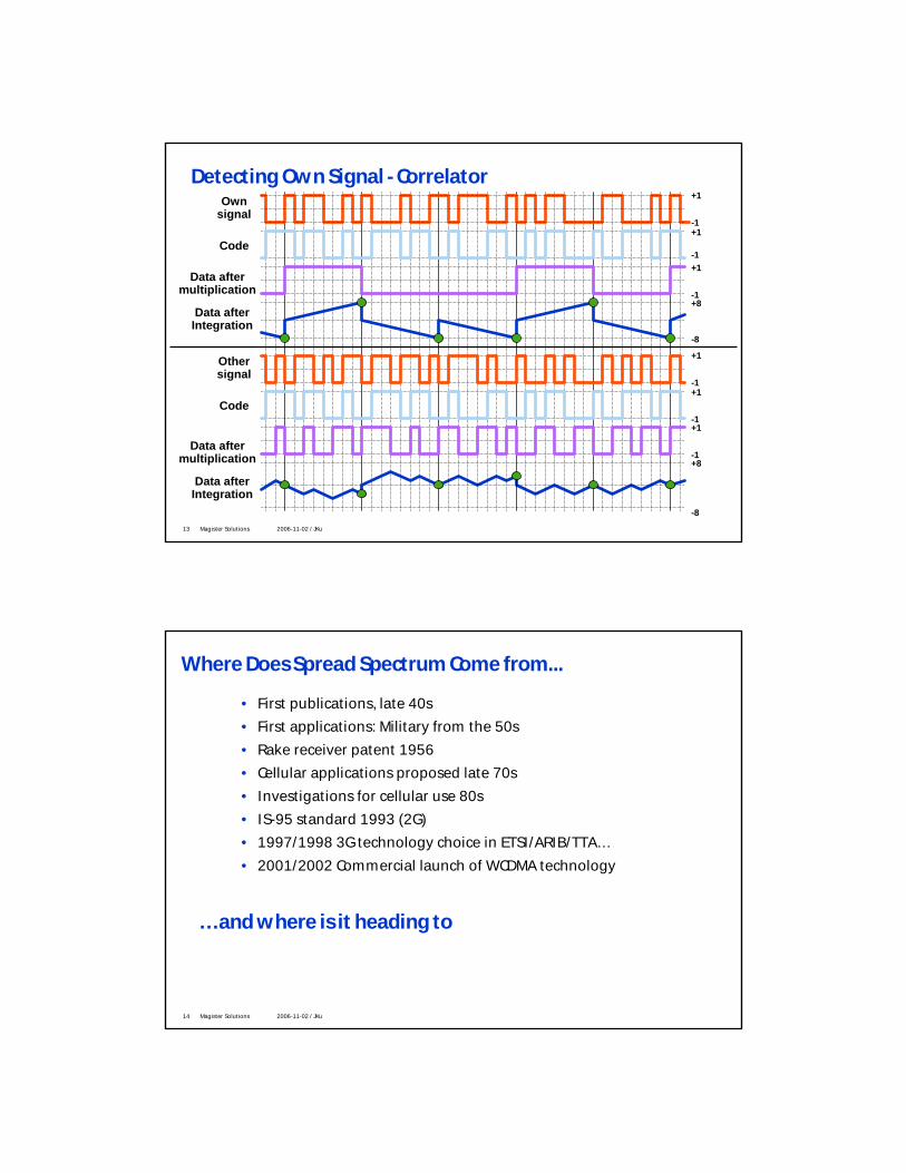
Detecting Own Signal - Correlator
Code
Data aftermultiplication
+1
+1
+1
-1
-1
-1
Ownsignal
+8
-8
Data afterIntegration
Code
Data aftermultiplication
+1
+1
+1
-1
-1
-1
Othersignal
+8
-8
Data afterIntegration
14 Magister Solutions 2006-11-02 / JKu
Where Does Spread Spectrum Come from...
• First publications, late 40s• First applications: Military from the 50s• Rake receiver patent 1956• Cellular applications proposed late 70s• Investigations for cellular use 80s• IS-95 standard 1993 (2G)• 1997/1998 3G technology choice in ETSI/ARIB/TTA…• 2001/2002 Commercial launch of WCDMA technology
… and where is it heading to

15 Magister Solutions 2006-11-02 / JKu
WCDMA
16 Magister Solutions 2006-11-02 / JKu
WCDMA system
• WDMA = Wideband Code Division Multiple Access• Users are separated with code sequences• All users share the same frequency (5 MHz carrier) and time• All data (control data, user traffic) are transmitted simultaneously• Uplink and downlink are frequency separated (2×5MHz)• Different users can use different services• One user can use different services at the same time (e.g. video phone, voice)• Bit-rate of one connection can change during the connection
f1
f1
f1
f1
f1
f1
f1
f1
f1
f1
f1f1
f1f1
f1
f1
CDMAFrequency
Usage Pattern
BS (Node B)f1 f1
BS (Node B)
Time
5 MHzMS1MS2MS3MS4
All users share the same frequency/time domain
MS1MS2MS3MS4

17 Magister Solutions 2006-11-02 / JKu
Main radio features of WCDMA
• Wide 3.84 Mcps bandwidth => good frequency & interferer diversity => low Eb/No
• coherent in both up- and downlink (RAKE) => low Eb/No
• fast power control (PC) => minimizes interference => high spectral efficiency
• robust RAKE diversity receiver => low complexity
• dynamic variable rate multiplexing => flexibility
18 Magister Solutions 2006-11-02 / JKu
Codes in WCDMA• Channelization Codes (=short code)
• length is dependent on spreading factor• Used for channel separation from the single source• Same codes in every cell / mobiles and therefore the additional scrambling code is
needed• Scrambling codes (=long code)
• very long (38400 chips), many codes available• Uplink: to separate different mobiles• Downlink: to separate different cells/sectors
• The correlation between two codes (two mobiles) is low
+1
-1Short code
+1Long code
-1+1
-1Combined
code
19 Magister Solutions 2006-11-02 / JKu
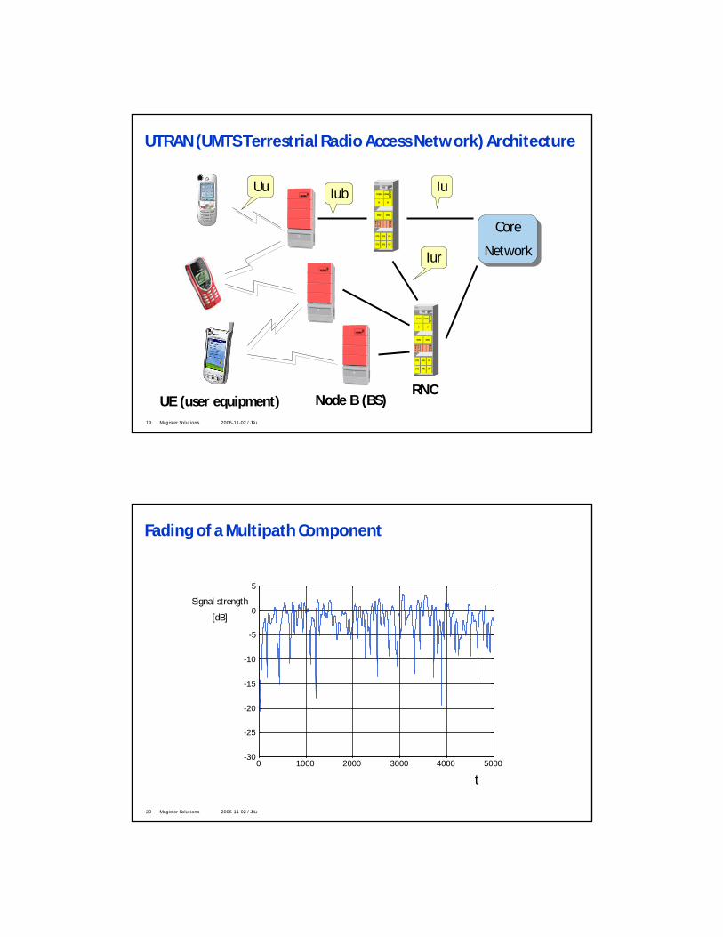
UTRAN (UMTS Terrestrial Radio Access Network) Architecture
STU CHU CMSTU CHU CM
STU CHU CM
WDU
CTU
WDU
OMU OMU
M M
CCMU CCMUCLS
PDE
DX 200
STU CHU CMSTU CHU CM
STU CHU CM
WDU
CTU
WDU
OMU OMU
M M
CCMU CCMUCLS
PDE
DX 200
IuIub
Iur
Uu
Core
Network
Core
Network
Node B (BS)RNC
UE (user equipment)
20 Magister Solutions 2006-11-02 / JKu
Fading of a Multipath Component
0 1000 2000 3000 4000 5000-30
-25
-20
-15
-10
-5
0
5
Signal strength
[dB]
t

21 Magister Solutions 2006-11-02 / JKu
UL Receiver Diversity
Fading
= Antenna 1= Antenna 2
Time
Amplitude
Antenna RAKEcombining(MRC)
RNC
22 Magister Solutions 2006-11-02 / JKu
DL Receiver Diversity
Fading
= Antenna 1= Antenna 2
Time
Amplitude
Antenna RAKEcombining(MRC)
RNC

23 Magister Solutions 2006-11-02 / JKu
WCDMA Power Control
f1 BS
MS 3
MS 2
MS 1
MS 4
The purpose of power control is to ensure that each user receives and transmits just enough energy to properly convey information while interfering with other users no more that necessary
MS1
MS2
MS3
MS4
With Optimal Power control
Received Power at the BS M
S1
MS2
MS3
MS4
Without Power control
24 Magister Solutions 2006-11-02 / JKu
WCDMA Handovers
Received signal strength
BS1
BS2
BS3
BS 2
BS 1
BS 3
MS
Distance from BS1
• Soft handover•MS handover between different base stations
• Softer handover•MS handover within one cell between different sectors
• Hard handover•MS handover between different frequencies or between WCDMA and GSM (or TDD)
Threshold
Base station diversity

25 Magister Solutions 2006-11-02 / JKu
Softer Handover
Sector/Antenna RAKEcombining(MRC)
RNC
• BTS internally• No extra transmissions
in the network side• Same Rake processing
basically• Provides additional
diversity gain
26 Magister Solutions 2006-11-02 / JKu
CNRNC
frame reliability info
frame reliability info
frame selection /duplication
except for the TPC symbolexactly the same information(symbols) is sent via air.Differential delay in order of fraction of symbol duration
• Needs extra transmissions in the network
• UL / DL diversity processing different
• MS: MRC RAKE combining• RNC: frame selection
Soft handover

27 Magister Solutions 2006-11-02 / JKu
Physical Layer Bit Rates (Downlink)
Spreadingfactor
Channelsymbol
rate(kbps)
Channelbit rate(kbps)
DPDCHchannel bitrate range
(kbps)
Maximum userdata rate with ½-
rate coding(approx.)
512 7.5 15 3–6 1–3 kbps256 15 30 12–24 6–12 kbps128 30 60 42–51 20–24 kbps64 60 120 90 45 kbps32 120 240 210 105 kbps16 240 480 432 215 kbps8 480 960 912 456 kbps4 960 1920 1872 936 kbps
4, with 3parallelcodes
2880 5760 5616 2.3 Mbps
• The number of orthogonal channelization codes = Spreading factor• The maximum throughput with 1 scrambling code ~ 2.5 Mbps or ~ 80 full rate speech users
Half rate speechFull rate speech
144 kbps384 kbps
2 Mbps
28 Magister Solutions 2006-11-02 / JKu
Packet Data Support
Idle
Mode
Cell
DCH
Cell
FACH
URA
PCH
Cell
PCH
Connected Mode
Cell DCH for active continuous transmission and for transmission of large infrequent data packets
Cell FACH, Cell PCH, URA PCH for optimized capacity, when infrequent or small frequent packets expected
29 Magister Solutions 2006-11-02 / JKu
QoS Support (1)
•Key Factors:•Simultaneous support of services with different QoS
requirements:• up to 210 Transport Format Combinations, selectable every 10 ms• going towards IP core networks greatly increases the usage of
simultaneous applications requiring different quality, e.g. real time vs. non-real time
•Optimized usage of different transport channels for supporting different QoS:
• use of different RRC states• simultaneous usage of different transport channels for different
QoS
30 Magister Solutions 2006-11-02 / JKu
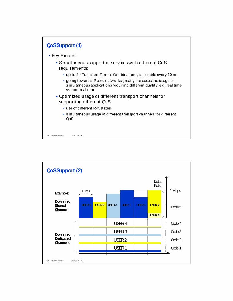
QoS Support (2)
Example:
DownlinkShared Channel
DownlinkDedicated Channels
USER 1
....
10 ms
USER 2 USER 3 USER 1 USER 1
USER 4
Data Rate
2 Mbps
Code 5
Code 4
Code 3
Code 2
Code 1USER 1
USER 2
USER 3
USER 4
USER 2

31 Magister Solutions 2006-11-02 / JKu
Asynchronous Network Operation
• WCDMA supports asynchronous, loosely synchronous and synchronous modes:• level of synchronism can be defined by the Network Operator• both tight synchronism and loose synchronism are provided for optimized
performance⇒ loose synchronism brings most of performance benefit, no need to provide chip synchronism for performance optimization
32 Magister Solutions 2006-11-02 / JKu
Capacity Enhancements
•More frequencies = carriers•Sectorisation•Low bit rate codec (e.g. AMR speech codec)
• Trade off between speech quality and capacity
•Transmit Diversity:• Diversity is essential in mobile communications, as a
mean to counterpart multipath fading and improve radio link reliability
•• BS TX diversity provides antenna diversity gain without BS TX diversity provides antenna diversity gain without the need of implementing 2 antenna reception diversity the need of implementing 2 antenna reception diversity in the mobilesin the mobiles
•• Receiver diversity and advanced receiversReceiver diversity and advanced receivers

33 Magister Solutions 2006-11-02 / JKu
High Speed Downlink Packet Access (HSDPA)
• The High Speed Downlink Packet Access (HSDPA) concept is added to release 5 to support higher data rates
• It is mainly intended for non-real time traffic, but can also be used for traffic with tighter delay requirements.
• Peak data rates up to 10 Mbit/s (theoretical data rate 14 Mbit/s)• Reduced retransmission delays• Improved QoS control (Node B based packet scheduler)• Spectral and code efficient solution for fully loaded sides
34 Magister Solutions 2006-11-02 / JKu
HSDPA features
•Agreed features in Release 5• Adaptive Modulation and Coding (AMC)
• QPSK or 16QAM
• Hybrid Automatic Repeat Request (HARQ)• Chase Combining• Incremental Redundancy
• Fast packet scheduling at Node B• E.g. Round robin, Proportional fair
• Short frame size (TTI = 2 ms)
•Potential features in Release 6• Multiple Input Multiple Output (MIMO)• Fast Cell Selection

35 Magister Solutions 2006-11-02 / JKu
HSDPA - general principle
• Fast scheduling is done directly in Node-B based on feedback information from UE and knowledge of current traffic state.
UE2
Channel quality(CQI, Ack/Nack, TPC)
Channel quality(CQI, Ack/Nack, TPC)
Data
Data
Users may be time and/or code multiplexed
New base station functions• HARQ retransmissions• Modulation/coding selection• Packet data scheduling (short TTI)
New base station functions• HARQ retransmissions• Modulation/coding selection• Packet data scheduling (short TTI)
UE1
0 20 40 60 80 100 120 140 160-202468
10121416
Time [number of TTIs]
QPSK1/4
QPSK2/4
QPSK3/4
16QAM2/4
16QAM3/4
Inst
anta
neou
s Es
No
[dB]
36 Magister Solutions 2006-11-02 / JKu
High Speed Uplink Packet Access (HSUPA)
• Peak data rates increased to significantly higher than 2 Mbps; Theoretically reaching 5.8 Mbps
• Packet data throughput increased, though not quite high numbers expected as with HSDPA
• Reduced delay from retransmissions.• Solutions
• Layer1 hybrid ARQ• NodeB based scheduling for uplink• Frame sizes 2ms & 10 ms
• Schedule in 3GPP• Part of Release 6• First specifications version completed 12/04• In 3GPP specs with the name Enhanced uplink DCH (E-DCH)

37 Magister Solutions 2006-11-02 / JKu
HSPA Peak Data Rates
5 codes QPSK
# of codes Modulation
5 codes 16-QAM
10 codes 16-QAM
15 codes 16-QAM
15 codes 16-QAM
1.8 Mbps
Maxdata rate
3.6 Mbps
7.2 Mbps
10.1 Mbps
14.0 Mbps
2 x SF4 2 ms10 ms
# of codes TTI
2 x SF2 10 ms
2 x SF2 2 ms
2 x SF2 +2 x SF4 2 ms
1.46 Mbps
Maxdata rate
2.0 Mbps
2.9 Mbps
5.76 Mbps
Downlink HSDPA• Theoretical up to 14 Mbps• Initial capability 1.8 – 3.6 Mbps
Uplink HSUPA• Theoretical up to 5.76 Mbps• Initial capability 1.46 Mbps
38 Magister Solutions 2006-11-02 / JKu
Multimedia Broadcast Multicast Service (MBMS)
• Efficient way to deliver the same multimedia content to several recipients in the same radio cell
• Downloading and streaming type of services possible• Mobile TV, weather reports, local information, …
• All MBMS services can be provided with cellular point-to-point (PtP) connections
• Users receives the data with fixed bitrate (e.g. 64 kbps, 128 kbps, 256 kbps)
p-t-p p-t-m

39 Magister Solutions 2006-11-02 / JKu
TD-CDMA and TD-SCDMA
40 Magister Solutions 2006-11-02 / JKu
Time Division Duplex
• TDD (Time Division Duplex) allows uplink and downlink on the same frequency band
• TDMA (Time Division Multiple Access) • is a digital technique that divides each frequency channel into multiple time-slots and thus
allows transmission channels to be used by several subscribers at the same time.
• CDMA (Code Division Multiple Access) • increases the traffic density in each cell by enabling simultaneous multiple-user access on the
same radio channel. Yet each user can interfere with another, which leads to multiple access interference (MAI).
• TD-(S)CDMA• In addition to the TDMA/TDD principle, TD-(S)CDMA uses CDMA to further increase the capacity
of the radio interface.• According to CDMA, user information bits are spread over a wider bandwidth by multiplying
the user data by pseudo-random bits (called chips) derived from CDMA spreading codes • Within each time slot a number of up to 16 CDMA codes may be transmitted

41 Magister Solutions 2006-11-02 / JKu
TDD Characteristics
•Utilization of unpaired band. • The TDD system can be implemented on an unpaired band while the FDD
system always requires a pair of bands.• 20 + 15 MHz allocated for TDD operation• Note that TDD band is not available in all countries (not in Japan)
•Discontinuous transmission. • Switching between transmission directions requires time, and the
switching transients must be controlled• Corruption of transmission is avoided by allocating a guard period.
1880 MHz 1980 MHzTDD FDD (UL) MSS
1900 MHz1920 MHz 2025 MHz
2010 MHz
DECT TDD FDD (DL) MSS
2110 MHz 2200 MHz2170 MHz
42 Magister Solutions 2006-11-02 / JKu
TDD Characteristics
•Interference between uplink and downlink. • Since uplink and downlink share the same frequency band, the signals in these two
transmission directions can interfere with each other.
•Asymmetric uplink/downlink capacity allocation.• In TDD operation, uplink and downlink are divided in the time domain. • It is possible to change the duplex switching point and move capacity from uplink
to downlink, or vice versa
• Reciprocal channel. • The fast fading depends on the frequency, and therefore, in FDD systems, the fast
fading is uncorrelated between uplink and downlink. • As the same frequency is used for both uplink and downlink in TDD, the fast fading
is the same in uplink and in downlink. • Knowledge of the fast fading can be utilized in power control and in adaptive
antenna techniques in TDD.

43 Magister Solutions 2006-11-02 / JKu
TDD Interference• TDD-to-TDD interference
• UE-to-UE interference• BS-to-BS interference
• TDD-to-FDD interference in border of TDD and FDD frequency allocation
• Synchronization
Operator A
Operator B
BS A
BS B
UE A
UE B
)1(,)(,)(, 112)1( +⋅+⋅−= nslotBSnslotBSnslotBS III θθ
slot
offset
tt
=θ
Operator A
Operator B
Time slot I-1 Time slot I Time slot I+1
Time slot I Time slot I+1Time slot I-1
toffset tslot
44 Magister Solutions 2006-11-02 / JKu
TD-CDMA
• The first release (Rel’99), issued in December 1999, defined the following two standards:
• UTRA FDD• UTRA TDD (3.84 Mcps mode of UTRA TDD, TDD HCR (High Chip Rate))
• These two standards were complementary: • UTRA-FDD to be employed in Micro and Macro Cells • UTRA TDD to cover micro, pico cells and indoor.
• In order to offer seamless services everywhere and every time, the two modes of the UTRA standard should be deployed together in a common network.
• UTRA TDD is the time division duplex mode of UTRA• It is intended to operate in the unpaired spectrum of the IMT-2000 band• UTRA TDD uses combined time division and code division multiple access• Frame length of UTRA TDD is 10 ms and it is divided into 15 slots. Each slot can be allocated for
uplink or downlink• For spectrum efficient operation DCA, PC, HO and other RRM algorithms are used

45 Magister Solutions 2006-11-02 / JKu
RRM Algorithms• Uplink power control
• PUE = αLPCCPCH + (1-α) L0 + IBTS + SIRTARGET+ ct• Downlink power control is ordinary fast closed loop power control• Handover
• Hard handover in which PCCPCH measurements for several BSs are made
• Measurement errors and processing delays are considered• Handover between TDD and FDD mode BSs
• Dynamic channel allocation• DCA allocates resource units (channel frequency, timeslot and code)• Slow DCA allocates resources for cells• Fast DCA allocates resources to bearer services
46 Magister Solutions 2006-11-02 / JKu
Differences in network level architecture
• The UTRA TDD differs from the FDD mode operation for those issues that are related to the different Layer 1.
• The protocols have been devised with the principle that there are typically common messages, but the information elements are specific for the mode (FDD or TDD) being used.
• The use of the Iur interface is not needed for soft handover purposes with TDD, as only one Node B is transmitting for one user.
• The core network does not typically see any difference, except that some of the highest data rate capabilities are not likely to be available.
• From the RNC point of view, the biggest issue to cope with is the radio resource management (RRM)
• Which in TDD is based on different measurements and resource allocation principles, along with the use of dynamic channel allocation (DCA).

47 Magister Solutions 2006-11-02 / JKu
TD-SCDMA
• In the second release of the UTRA standard (called Release 4, March 2001)
• Additional features of TD-SCDMA radio technology were also included in the specification for this UMTS Standard.
• According to Release 4, TD-SCDMA radio interface is integrated in 3GPP as the 1.28 Mcps option of the UTRA TDD, also called TDD LCR (TDD Low Chip Rate).
• Using a chip rate of 1.28 Mcps allows a carrier bandwidth of 1.6 MHz. • According to its operating license, the network operator can deploy multiple
TD-SCDMA 1.6 MHz carriers. • In order to support very high bit rates (up to 2Mbps), the use of variable
spreading factor and multicode connections (code pooling) is supported.
48 Magister Solutions 2006-11-02 / JKu
Radio channel access
• TD-SCDMA uses a 5ms frame subdivided into 7 time slots• Can be flexibly assigned to either several users or to a single user who may require
multiple time slots.
• TDD principles permit traffic to be in uplink and downlink using different time slots in the same frame.
• For symmetric services used e.g. during telephone and video calls (multimedia applications) the time slots are split equally between the downlink and uplink.
• For asymmetric services used e.g. with Internet access (download), more time slots are used for the downlink than the uplink.
• It is possible to change the switching point between uplink and downlink, depending on the capacity requirement between uplink and downlink.

49 Magister Solutions 2006-11-02 / JKu
Radio channel access
• The ability of adapting the uplink/downlink symmetry according to data load within a single unpaired frequency band optimizes the capacity of the air interface, thus utilizing the spectrum more efficiently.
• In contrast, the FDD (Frequency Division Duplex) scheme – employed by W-CDMA and cdma2000 – uses a pair of frequency bands for up- and downlink
• With asymmetric loads, portions of the spectrum are occupied but not used for data transfer.
• These idle resources cannot be utilized for any other service, leading to an inefficient use of the spectrum.
• Future mobile applications will require an efficient use of the available spectrum and the ability to handle strong asymmetric data traffic
• TD-SCDMA was seen to these requirements and can be considered as a candidate technology for 3G services.
50 Magister Solutions 2006-11-02 / JKu
TD-SCDMA
• Dynamic Channel Allocation (DCA) • Making an optimal use of these degrees of freedom,TD-SCDMA provides an adaptive allocation
of the radio resources according to the interference scenario, minimizing inter-cell interference.
• Mutual Terminal Synchronization• By accurately tuning the transmission timing of each individual terminal, TD-SCDMA improves
the terminal trace ability reducing time for position location calculation and search time for handover searching.
• Thanks to synchronization, TD-SCDMA does not need soft handover, which leads to a better cell coverage, reduced inter-cell interference and low infrastructure and operating costs.
• Smart Antennas • are beam steering antennas which track mobile usage through the cell and distribute the
power only to cell areas with mobile subscribers. • Without them, power would be distributed over the whole cell. • Smart antennas reduce multi-user interference, increase system capacity, increase reception
sensitivity, lower transmission power while increasing cell range.

51 Magister Solutions 2006-11-02 / JKu
TD-SCDMA
• The efficiency of the Joint Detection receiver in TD-SCDMA technology is based on the TDMA/TDD operation and on the limited number of codes employed
• The total number of users per radio carrier is distributed over the different time slots of the basic TDMA frame, so that a maximal number of 16 codes per time slot per radio carrier can be easily processed in parallel and detected.
• Due to the high number of codes used by cdma 2000 and W-CDMA the implementation of an optimal multi-user receiver in these systems is difficult, since the implementation complexity is an exponential function of the numbers of codes.
• Adopted by ITU and 3GPP, TD-SCDMA is a full 3G Radio Standard, which covers all radio deployment scenarios: voice and data services, packet and circuit switched transmissions for symmetric and asymmetric traffic, pico, micro and macro coverage for pedestrian and high mobility users.
• Beam-steering smart antennas, joint detection, terminal synchronization and dynamic channel allocation minimize radio interference leading to high spectrum efficiency
52 Magister Solutions 2006-11-02 / JKu
TDD Conclusions
• Mainstream business driver for TDD is still missing • On a global scale terminal, infrastructure and operator support for TDD is likely to be
very limited• HCR TDD as a wide band system solution could allow easier integration with WCDMA
than LCR TDD solutions
• For mobile operators FDD WCDMA with HSPA (and I-HSPA) extension constitute a more attractive route to providing broadband wireless services.
• Unlike HSDPA, TDD lacks synergies with FDD: fundamentally different RF and radio resource management.
• Interference problems with spectrum plan in Europe need to be solved • Inter cell and inter network synchronization and time slot coordination will most
likely be required in practice
• TD-SCDMA is a potential 3G technology candidate in China

53 Magister Solutions 2006-11-02 / JKu
cdma2000
54 Magister Solutions 2006-11-02 / JKu
cdma2000
• In addition to UTRA FDD and TDD modes in the global ITU-R IMT-2000 CDMA framework, the third mode is the Multicarrier (MC) CDMA mode.
• Based on the cdma2000 multicarrier option • Standardized by the 3rd Generation Partnership Project 2 (3GPP2)
• 3G evolution for operators with an existing IS-95 (or 1X) network • Especially if a third generation network is to be deployed on the same frequency
spectrum as an existing IS-95 network.
IS-95 (1x)
1.25 MHz
3.75 MHz
3 x 1.25 MHz
1.25 MHz
Multicarrier (3x)
Uplink
Downlink

55 Magister Solutions 2006-11-02 / JKu
cdma2000
• The name for the MC mode comes from the downlink transmission direction, where multiple (up to 12) parallel narrowband CDMA carriers are transmitted from each base station.
• Each carrier’s chip rate is 1.2288 Mcps, equal to the IS-95 chip rate. • The uplink direction is direct spread, very similar to UTRA FDD, with multiple
chip rate of 1.2288 Mcps. • The first ITU release of cdma2000 will adopt up to three carriers (known as 3X
mode) at a chip rate up to 3.6864 Mcps. • One difference in terminology worth noting is the use of the term
• ‘reverse link’ instead of ‘uplink’• ‘forward link’ instead of ‘downlink’, in cdma2000 documentation.
• Currently, there do not seem to be commercial commitments for actually adopting the MC mode, but instead the focus has been more on the further development of narrowband operation.
56 Magister Solutions 2006-11-02 / JKu
1xEV-DO and 1xEV-DV
• The 1X development work has produced different versions of the specifications, with the latest work being done on the 1xEV-DO and 1xEV-DV.
• 1xEV-DO (DO = Data Only) • Data only system that uses a separate carrier from voice or other circuit switched
services
• 1xEV-DV (DV = Data and Voice) • Mixed voice and packet data operation on the same carrier • Uses similar technology as High-speed Downlink Packet Access (HSDPA) in WCDMA
• The 1xEV-DO and 1xEV-DV have peak rate capabilities of the order of 2.4 Mbps and 3 Mbps.
• If there is a need to extend the capabilities beyond that, then wider bandwidth is necessary

57 Magister Solutions 2006-11-02 / JKu
Mixed Voice/Data in 1xEV-DO
• 1xEV-DO supports only data services• 1x carriers can be used to handle voice calls
Power
Max capacity
Power
Max capacity
5 MHz
EV-DO
cdma2kvoice
cdma2kvoice
Blocking for speech
Low data throughput
Unusedcapacity
= data
= voice
All capacity fully utilizedGSM, EDGE or WCDMAGSM, EDGE or WCDMA
2 x cdma2k + EV-DO2 x cdma2k + EV-DO
58 Magister Solutions 2006-11-02 / JKu
Logical channel
• Corresponding to the UTRA term ‘transport channels’ the term ‘logical channels’is used for cdma2000.
• The following logical channels are defined in the cdma2000 (Release A) specification, which was completed at the end of 1999
• Dedicated Traffic Channel (f/r-dtch). A point-to-point logical channel that carries data or voice traffic over a dedicated physical channel
• Common Control Channels (f/r-cmch control). These are used to carry MAC messages with shared access for several terminals.
• Dedicated Signaling Channel (f/r-dsch). A point-to-point logical channel that carries upper layer signaling traffic over a dedicated physical channel, for a single terminal.
• Common Signaling Channel (f/r-csch). A point-to-multipoint logical channel that carries upper layer signaling traffic over a common physical channel, with shared access for several terminals.

59 Magister Solutions 2006-11-02 / JKu
Physical Channels
• The MC mode provides basically the same functionality as does UTRA FDD • Broadcast Channel, Random Access Channel, paging channel, …
• The UTRA common channel types such as shared channels, uplink Common Packet Channel, and so on, have no direct counterparts in the MC mode, but the same functionalities are implemented by means of different arrangements.
• Data channel in downlink is the Supplemental Channel, which has similarities with the Downlink Shared Channel (DSCH) in UTRA FDD
• The Supplemental Channel also exists in the uplink, but not as an enhancement for the Random Access Channel like the Common Packet Channel in UTRA FDD.
• The typical duration of the random access message is longer than in UTRA• In UTRA the change to a dedicated channel takes place earlier• Thus, the Random Access Channel transmission may last over several frames. • To avoid CDMA near–far problems, a common power control channel may be used to transmit
power control information• The MC mode employs a quick paging channel that is used to indicate to the terminal
when to listen to the actual paging channel itself.
60 Magister Solutions 2006-11-02 / JKu
Uplink Spreading and Modulation
• In terms of signal bandwidth, there is not much difference between the MC mode’s multicarrier (uplink) chip rate of 3.6864 Mcps and UTRA FDD’s 3.84 Mcps.
• When higher data rates are desired with the MC mode, the Supplemental Channel is used in parallel with the Fundamental Channel, which provides only a limited set of possible lower data rates.
• The uplink spreading is done with Walsh functions, while in UTRA FDD, OVSF codes are used.
• Variable rate spreading is not used in the MC mode during the connection on a frame-by-frame basis, as no rate information is provided in the physical layer signaling.
• The uplink long code used for scrambling has a period of 242 - 1 chips. • This is significantly longer than in UTRA FDD, where the code period is 38 400 chips for the
dedicated channels, and the code length is only 256 chips for short scrambling codes.
• For the adjacent channel attenuation, 40 dBm attenuation in the signal level should be reached outside 4.44 MHz bandwidth.

61 Magister Solutions 2006-11-02 / JKu
Downlink spreading and modulation
• The downlink modulation is obviously characterized by its multi-carrier nature. • The downlink carriers can be operated independently, or the terminal can
demodulate them all. • The benefit of receiving on all carriers is the frequency diversity that is improved
over a single 1.2288 Mcps carrier.
• As each carrier contains a pilot channel for channel estimation, they can also be sent from different antennas if desired, to allow additional diversity.
• This is similar to the transmission diversity methods in UTRA.
• The channel on each carrier is spread with Walsh functions using a constant spreading factor during the connection
• Like the OVSF codes in UTRA, the Walsh functions separate channels from the same source and have similar orthogonality for transmission from a single source.
• The spreading factors for data transmission range from 256 down to 4.
62 Magister Solutions 2006-11-02 / JKu
Downlink spreading and modulation
• Downlink scrambling is characterized by the use of a single code throughout the system.
• The MC mode is operated with synchronized base stations, • A single code is used• The different base stations using a different phase of the same code.
• The number of available phases is 512, corresponding to the number of UTRA FDD primary scrambling codes.
• In practical networks, the phases with minimum separation are often avoided in order to relax the requirements associated with timing issues in the network planning process.

63 Magister Solutions 2006-11-02 / JKu
Power control procedure
• The basic power control procedure is rather similar in the MC mode and UTRA FDD.
• Fast closed loop power control is available in both uplink and downlink• 1500 Hz with a normal step size of 1 dB in UTRA FDD• 800 Hz in the MC mode.
• The open loop power control monitors the received signal strength in the downlink.
• If threshold values are exceeded it can alter the terminal transmission power • The pairing of open loop power control with closed loop power control can be
turned off by the network • This option is often used in the existing IS-95 networks as well
• In the MC mode, the pilot symbols do not exist on the dedicated channel, thus the only symbols that can be used to aid the SIR estimation are the power control symbols as they preserve the power level unchanged with respect to changes in the data rate
64 Magister Solutions 2006-11-02 / JKu
Cell search
• There are essential differences in the cell search procedure between the MC mode and UTRA FDD.
• The MC mode uses time-shifted versions of the single scrambling code for all base stations in the network
• Upon powering on • The terminal starts searching for the single sequence• The search will continue until one or more code phases have been detected• As all the cells are synchronized, only a single sequence is needed in the system, and the
terminal can search for the different phases of that single sequence. • In UTRA there are 512 different cell-specific scrambling codes
• A similar procedure would be too complex or too time-consuming and therefore the search in UTRA starts from the synchronization code word common to all cells
• As in UTRA, the cell search differs depending on whether an initial search is considered or a search is done for target cells for handover purposes.
• In the connected mode the terminal will get a list of the neighboring cells and will perform the search based on the information on the PN-offset of the target cells.

65 Magister Solutions 2006-11-02 / JKu
Handover
• The MC mode supports handovers to other systems with multimode terminals• IS-95• Releases later than Release ’99 are expected to include the necessary
enhancements for measuring and handing over to GSM or UTRA FDD from the physical layer perspective.
• On the network side, the degree of difficulty will depend on whether one is dealing with a simple voice call only or whether advanced data services are included.
• Possible commercial interest for such equipment remains to be seen as well.• Unlike in UTRA, the MC mode does not offer methods like compressed mode for
inter frequency measurements. • The terminal either has to be dual receiver one, or the terminal will do
measurements by simply ignoring the data sent on the downlink direction.
66 Magister Solutions 2006-11-02 / JKu
Conclusions
• Overview of 3G technologies were given• WCDMA
• 3G evolution for GSM networks (e.g. Europe)• Most adopted 3G technology
• TD-(S)CDMA• TD-SCDMA is a potential 3G technology candidate in China
• cdma2000• 3G evolution for IS-95 networks (e.g. Korea, USA, China)
• Questions?