8 challenger
DESCRIPTION
COLUMBIA , CHALLENGER , SPACESHIP , NASA , SPACE PROGRAM , PAPERMODELTRANSCRIPT
LOADED
LOADED
LOADED
LOADED
LOADED
LOADED
LOADED
LOADED
LOADED
LOADED
LOADED
LOADED
http://www.axmpaperspacescalemodels.com
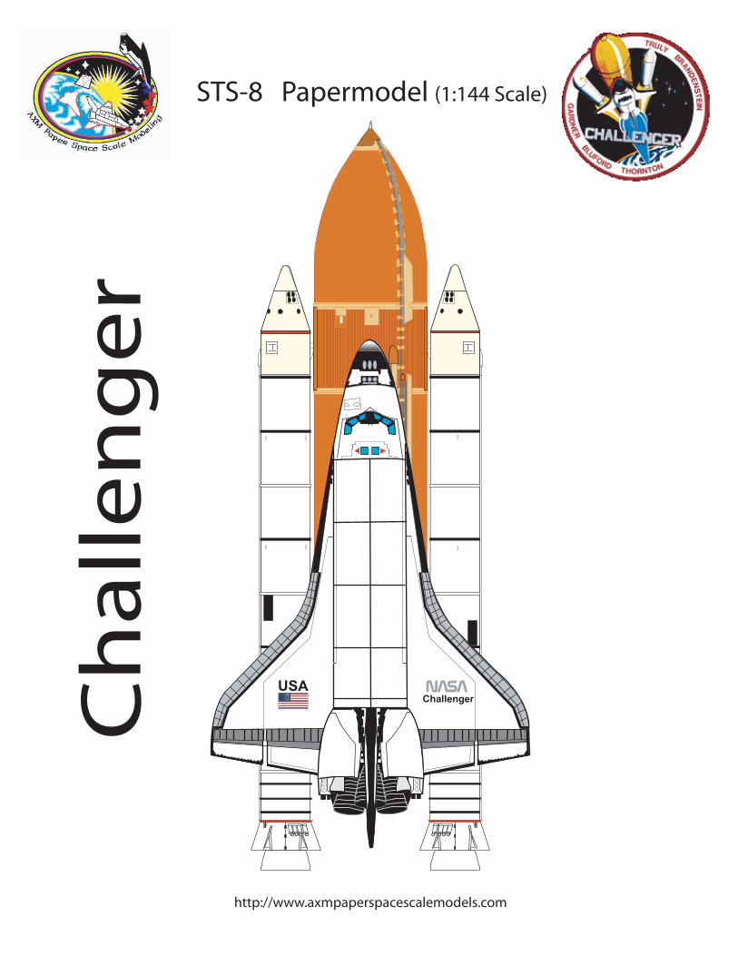
STS-8 Papermodel (1:144 Scale)
Ch
all
en
ge
r
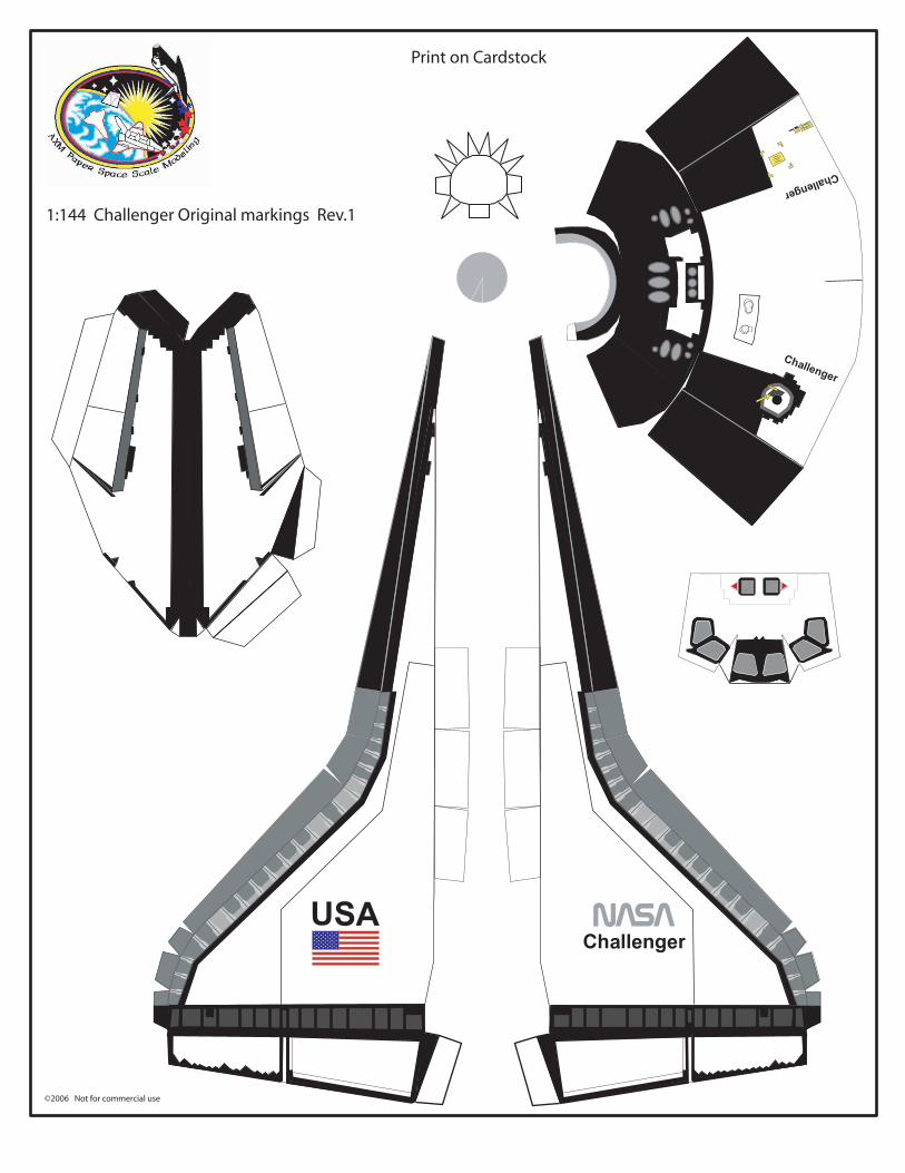
Print on Cardstock
©2006 Not for commercial use
1:144 Challenger Original markings Rev.1
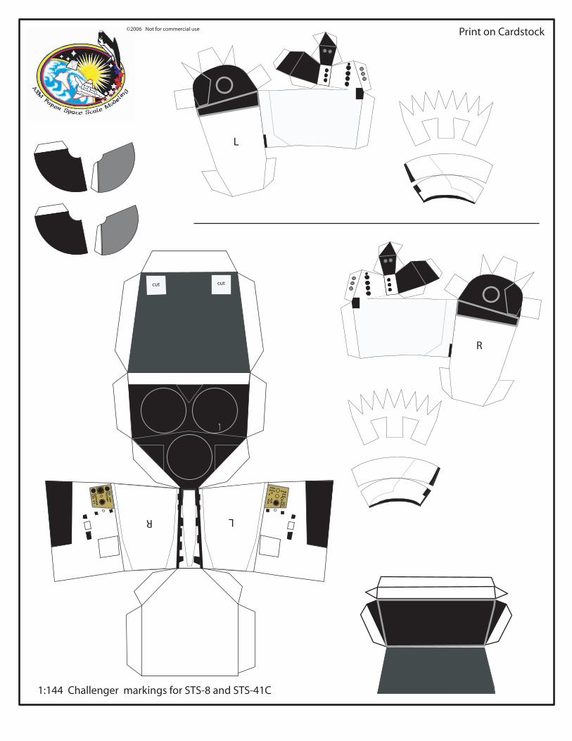
cut cut
©2006 Not for commercial use Print on Cardstock
1:144 Challenger markings for STS-8 and STS-41C
LR
R
L
AD
©2006 Not for commercial use
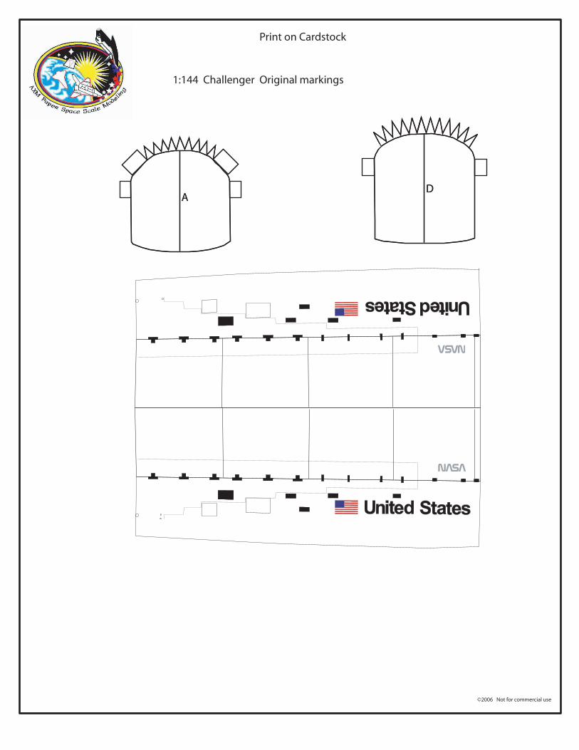
Print on Cardstock
1:144 Challenger Original markings
AD
���
©2007 Not for commercial use
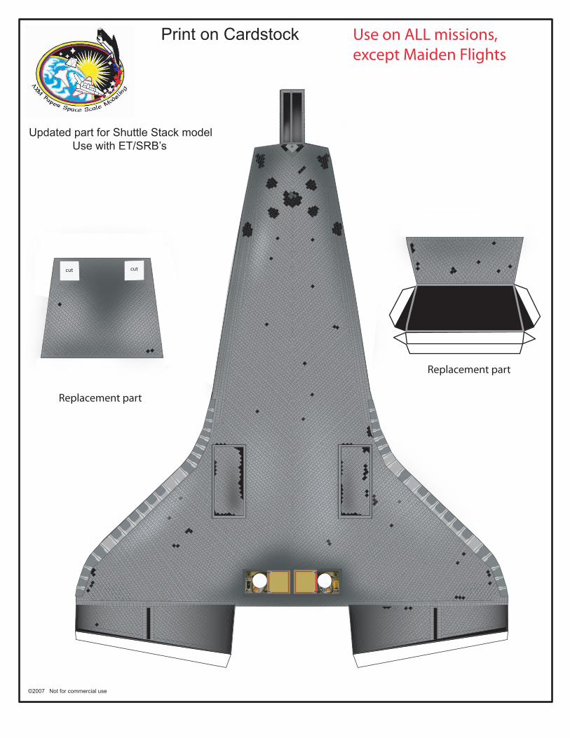
Print on Cardstock
Updated part for Shuttle Stack model Use with ET/SRB’s
cut cutcut cut
Replacement part
Replacement part
Use on ALL missions,except Maiden Flights
Glu
e p
aylo
ad b
ox h
ere
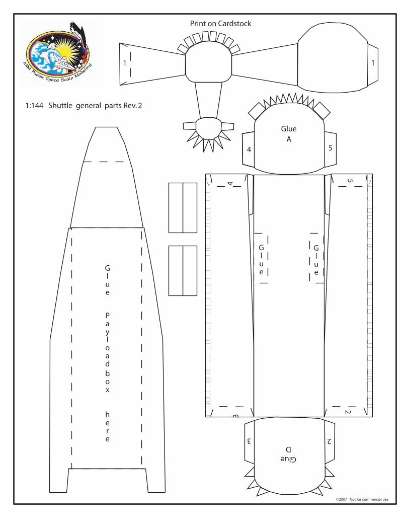
Glue
Payload
box
here
A
D
Glue
Glue
Glue
Glue
Print on Cardstock
©2007 Not for commercial use
1:144 Shuttle general parts Rev. 2
1 1
2
2
3
3
4
4
5
5
©2007 Not for commercial use
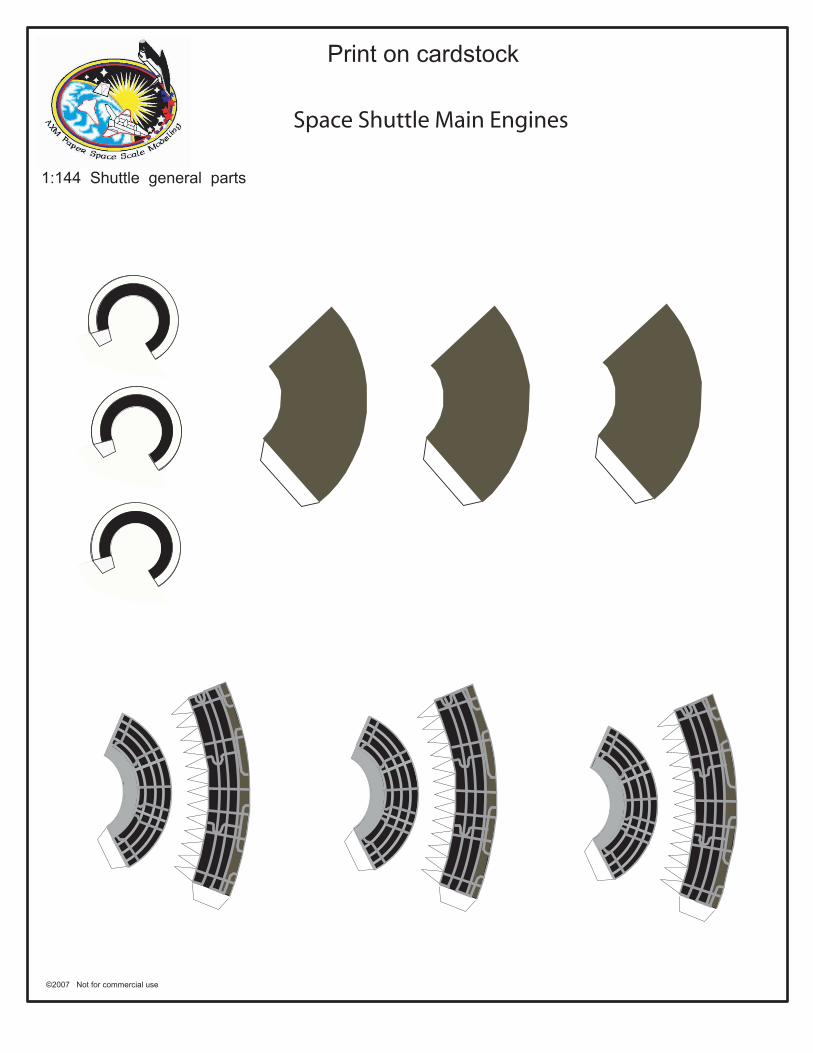
Print on cardstock
1:144 Shuttle general parts
Space Shuttle Main Engines

Print on Cardstock
©2007 Not for commercial use
New Shuttle Cabin Windows
Columbia Discovery
Atlantis
(replacement parts)
(Modifications 1, 2, 3)
(Rest of modifications)
Challenger
Check REFERENCE Page from Websiteto look for corresponding Missions
(All modifications)
(Modifications 1, 2, 3, 4, 5, 6)
(Modification 7)
(Modification 8, 9)
(Modif. 1,2,3)
Atlantis modif. 4
Endeavour modif. 2, 3Atlantis modif. 5
Endeavour modif. 1
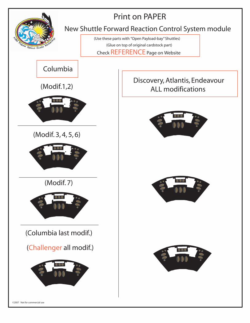
Print on PAPER
©2007 Not for commercial use
New Shuttle Forward Reaction Control System module(Use these parts with “Open Payload-bay” Shuttles)
(Glue on top of original cardstock part)
Columbia
(Modif.1,2)
(Modif. 3, 4, 5, 6)
(Modif. 7)
(Columbia last modif.)
(Challenger all modif.)
Discovery, Atlantis, Endeavour ALL modifications
Check REFERENCE Page on Website
���
���
©2007 Not for commercial use
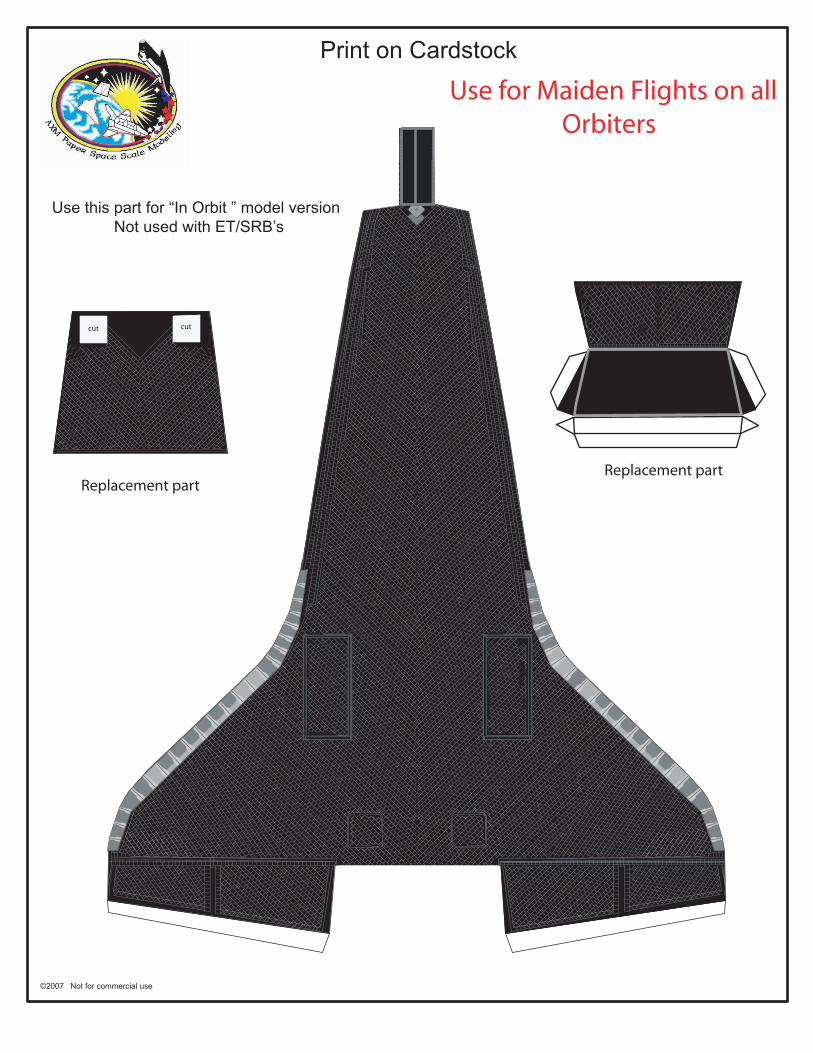
Print on Cardstock
Use this part for “In Orbit ” model version Not used with ET/SRB’s
cut cutcut cut
Replacement partReplacement part
Use for Maiden Flights on all Orbiters
���
���
©2007 Not for commercial use
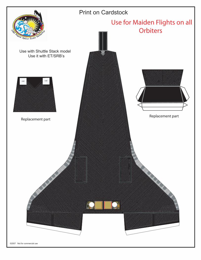
Print on Cardstock
Use with Shuttle Stack model Use it with ET/SRB’s
cut cutcut cut
Replacement partReplacement part
Use for Maiden Flights on all Orbiters
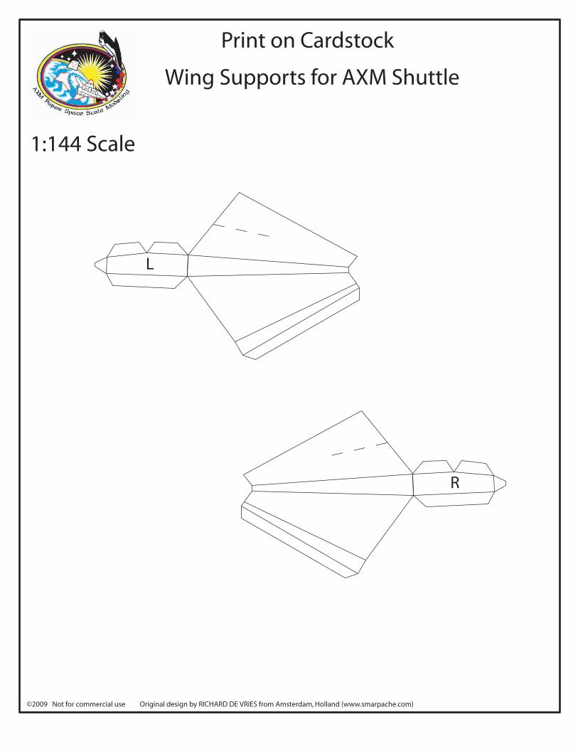
Print on Cardstock
©2009 Not for commercial use Original design by RICHARD DE VRIES from Amsterdam, Holland (www.smarpache.com)
1:144 Scale
Wing Supports for AXM Shuttle
L
R
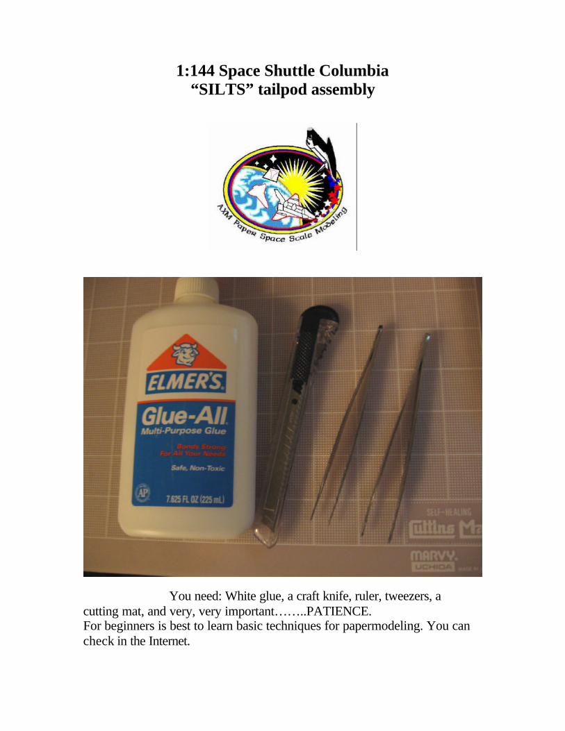
1:144 Space Shuttle Columbia
“SILTS” tailpod assembly
You need: White glue, a craft knife, ruler, tweezers, a cutting mat, and very, very important……..PATIENCE. For beginners is best to learn basic techniques for papermodeling. You can check in the Internet.

The following pages show a sequence of photos as a guide to build this model.
Prepare the tailfin parts Make a cylinder out of the tailpod
Prepare the drag chute box Fold these areas (inward) Insert cylinder into the hole. Folded areas will cover the cylinder when tailfin is finally closed.
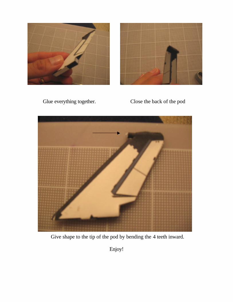
Glue everything together. Close the back of the pod
Give shape to the tip of the pod by bending the 4 teeth inward.
Enjoy!
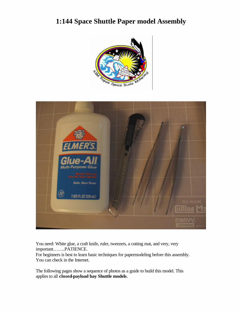
1:144 Space Shuttle Paper model Assembly
You need: White glue, a craft knife, ruler, tweezers, a cutting mat, and very, very important……..PATIENCE. For beginners is best to learn basic techniques for papermodeling before this assembly. You can check in the Internet. The following pages show a sequence of photos as a guide to build this model. This applies to all closed-payload bay Shuttle models.
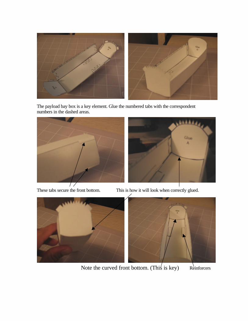
The payload bay box is a key element. Glue the numbered tabs with the correspondent numbers in the dashed areas.
These tabs secure the front bottom. This is how it will look when correctly glued.
Note the curved front bottom. (This is key) Reinforcers
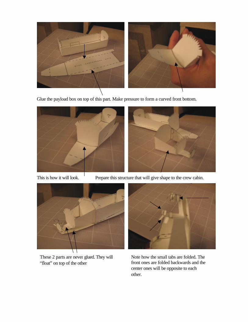
Glue the payload box on top of this part. Make pressure to form a curved front bottom.
This is how it will look. Prepare this structure that will give shape to the crew cabin.
.
These 2 parts are never glued. They will “float” on top of the other
Note how the small tabs are folded. The front ones are folded backwards and the center ones will be opposite to each other.

This is how it will look. .
Align the lines for symmetry.
Glue both ends A and D. The walls need to be glued too. Let it dry.
Crew cabin and payload box need to be glued perfectly as photo show.
Give a curved shape to this part. The walls are folded on this line.
Fold tabs towards the front.
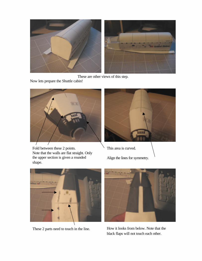
These are other views of this step. Now lets prepare the Shuttle cabin!
Fold between these 2 points. Note that the walls are flat straight. Only the upper section is given a rounded shape.
This area is curved. Align the lines for symmetry.
These 2 parts need to touch in the line. How it looks from below. Note that the black flaps will not touch each other.

Give shape to the nose. Insert the small piece with the small tabs folded outwards.
Close this part with the “teeth” protruding outwards.
Glue the nosecap covering the teeth.
Bend the lateral windows inward and glue to the tab.
This is how it will look.

Glue the indicated areas only.
Prepare the belly section by cutting the 2 holes.
This is how it will look.
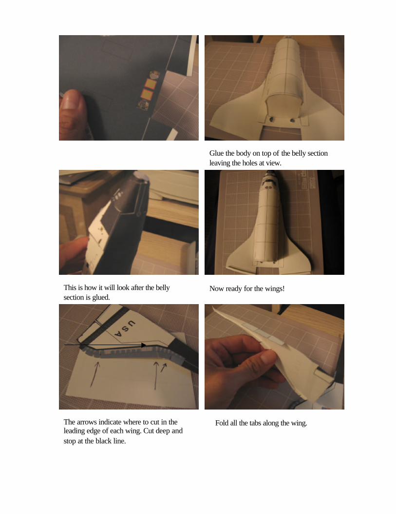
Glue the body on top of the belly section leaving the holes at view.
This is how it will look after the belly section is glued.
Now ready for the wings!
The arrows indicate where to cut in the leading edge of each wing. Cut deep and stop at the black line.
Fold all the tabs along the wing.
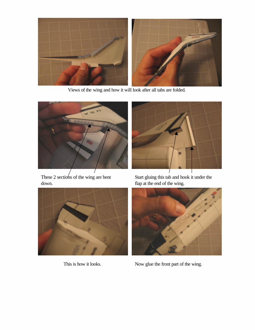
Views of the wing and how it will look after all tabs are folded.
Start gluing this tab and hook it under the flap at the end of the wing.
These 2 sections of the wing are bent down.
This is how it looks. Now glue the front part of the wing.
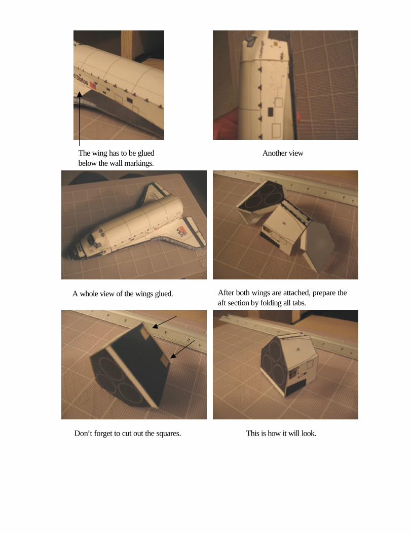
The wing has to be glued below the wall markings.
After both wings are attached, prepare the aft section by folding all tabs.
Don’t forget to cut out the squares.
Another view
A whole view of the wings glued.
This is how it will look.
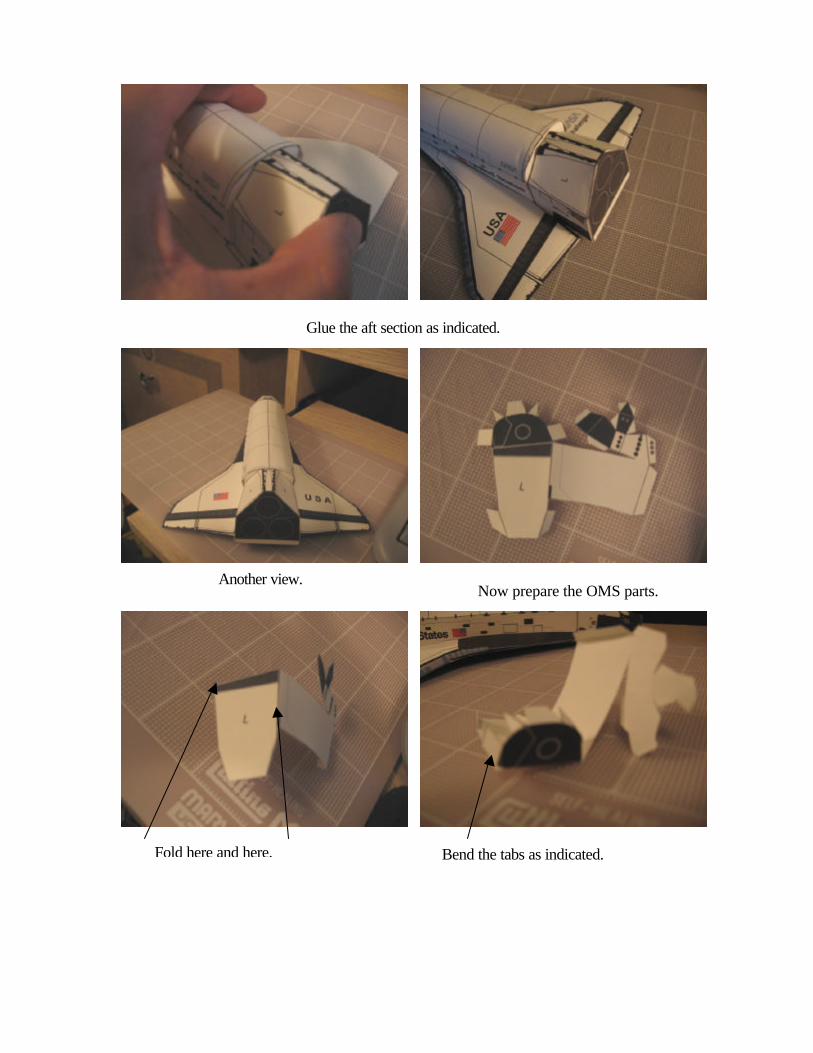
Glue the aft section as indicated.
Another view. Now prepare the OMS parts.
Fold here and here. Bend the tabs as indicated.
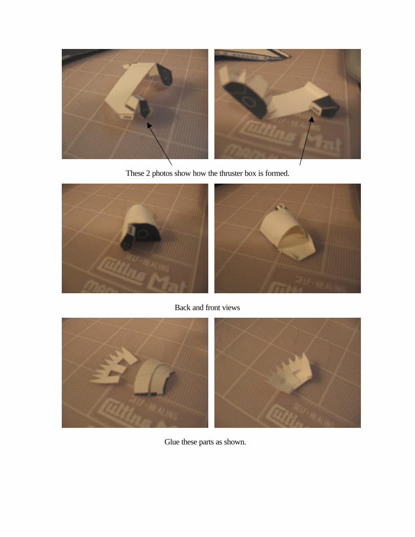
These 2 photos show how the thruster box is formed.
Back and front views
Glue these parts as shown.
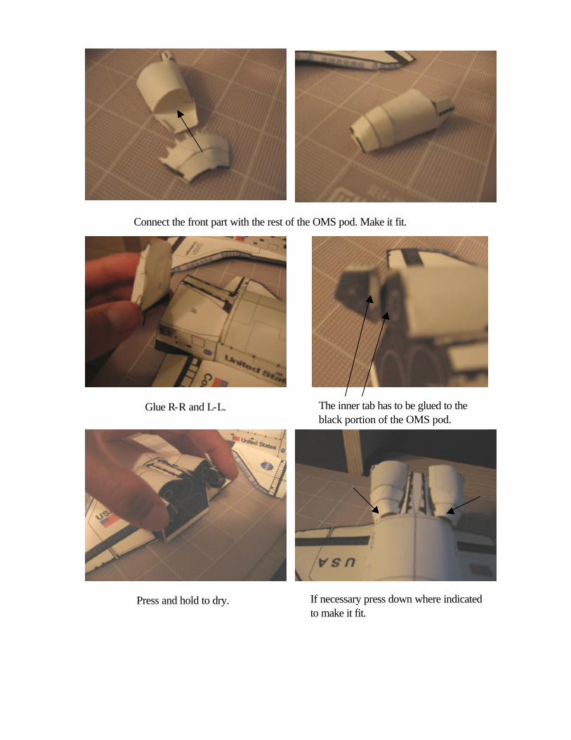
Connect the front part with the rest of the OMS pod. Make it fit.
If necessary press down where indicated to make it fit.
The inner tab has to be glued to the black portion of the OMS pod.
Press and hold to dry.
Glue R-R and L-L.
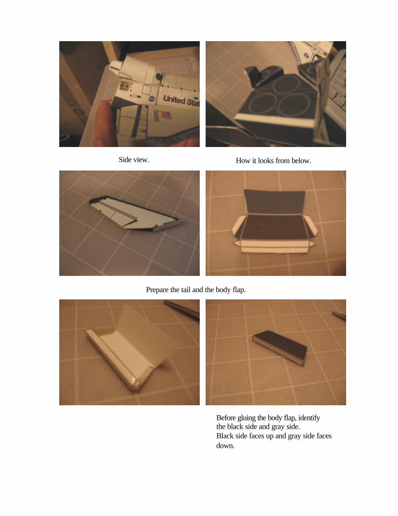
How it looks from below. Side view.
Prepare the tail and the body flap.
Before gluing the body flap, identify the black side and gray side. Black side faces up and gray side faces down.
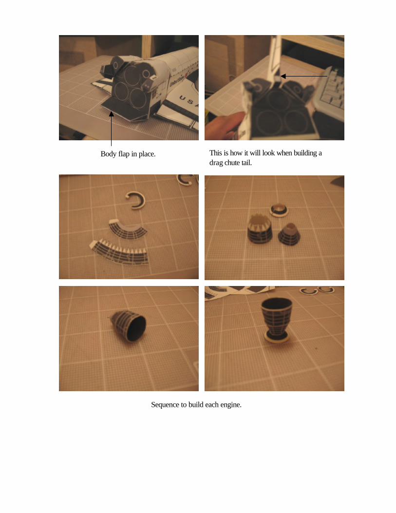
This is how it will look when building a drag chute tail.
Body flap in place.
Sequence to build each engine.

IMPORTANT: one of the 3 engines needs to be glued in an angle. That will go as first engine.
Orbiter complete. Enjoy building your 1:144 Space Shuttle paper model!
http://www.axmpaperspacescalemodels.com

©2006 Not for commercial use
Print on Cardstock
1:144 External Tank general parts
LR
©2007 N
ot fo
r com
mercial u
sePrin
t on
Card
stock
©2007 Not for commercial use
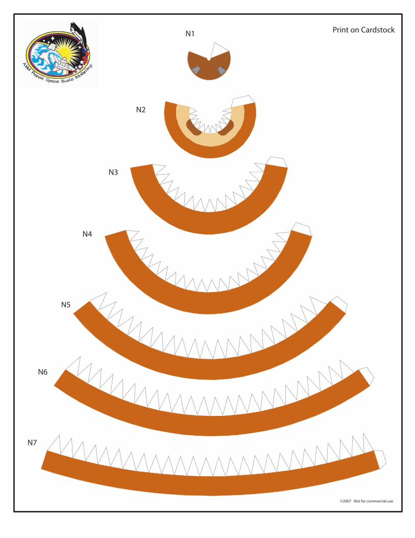
Print on Cardstock
N2
N3
N4
N5
N6
N7
N1
CutCut
©2007 Not for commercial use
Print on Cardstock
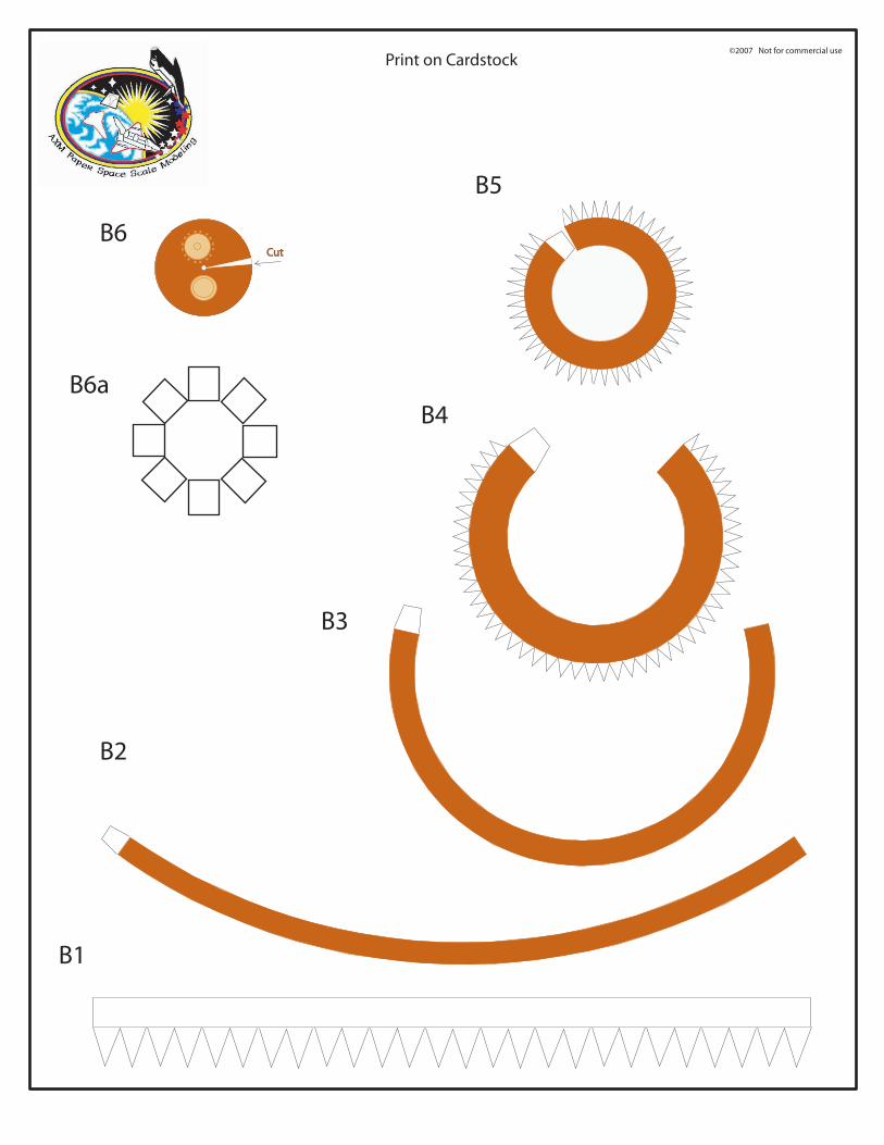
B1
B2
B3
B4
B5
B6
B6a

LR
©2007 Not for commercial use
Print on Cardstock
T1
LO2
Intertank: Stack 1B
LO2
T2

©2007 Not for commercial use
Print on Cardstock
C C
C1
C1
External
Internal
Fold
1 21
2
FoldFold
Fold
L R
Bipod
FoldFold

©2006 Not for commercial use
Important! Print on Paper only
top
bottom
LO2 line
©2006 N
ot fo
r com
mercial u
sePrin
t on
Card
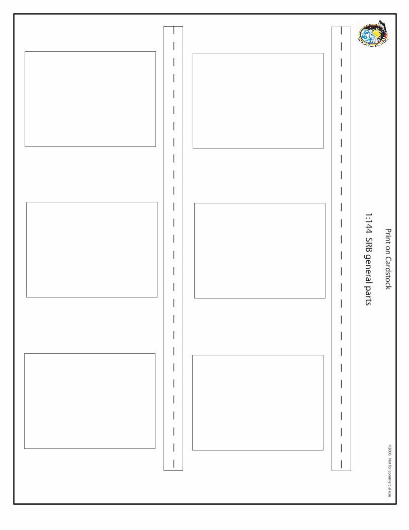
stock
1:144 SRB g
eneral p
arts

L R
©2007 Not for commercial use
Print on Cardstock
connectorconnector
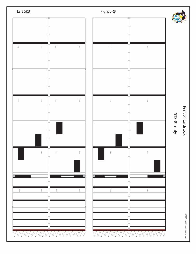
Left SRB Right SRB©
2007 No
t for co
mm
ercial use
Print o
n C
ardsto
ck
STS-8 on
ly
LOA
DED
LOA
DED
LOA
DED
LOA
DED
LOA
DED
LOA
DED
LOA
DED
LOA
DED
LOA
DED
LOA
DED
LOA
DED
LOA
DED
LOA
DED
LOA
DED
LOA
DED
LOA
DED
LOA
DED
LOA
DED
LOA
DED
LOA
DED
LOA
DED
LOA
DED
LOA
DED
LOA
DED

©2006 Not for commercial use
Print on Cardstock
glue glue
Skirt
Nozzle in
Nozzle out
Skirt
Nozzle out
LeftRight
Nozzle in
©2007 N
ot fo
r com
mercial u
se
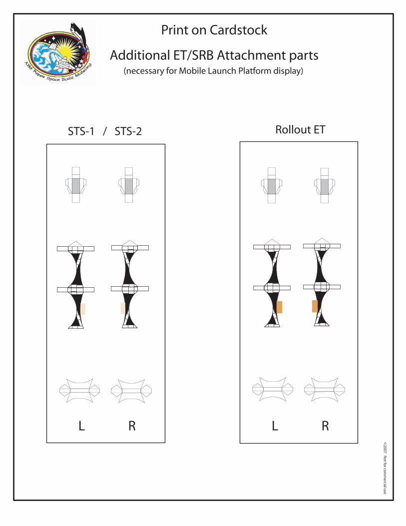
Print on Cardstock
Additional ET/SRB Attachment parts(necessary for Mobile Launch Platform display)
Rollout ETSTS-1 / STS-2
L R L R
©2007 N
ot fo
r com
mercial u
se
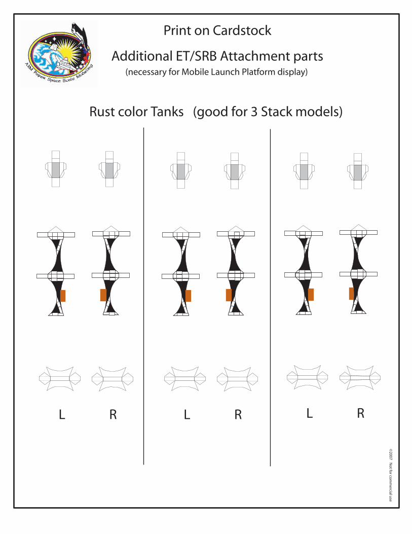
Print on Cardstock
Additional ET/SRB Attachment parts(necessary for Mobile Launch Platform display)
L R L R L R
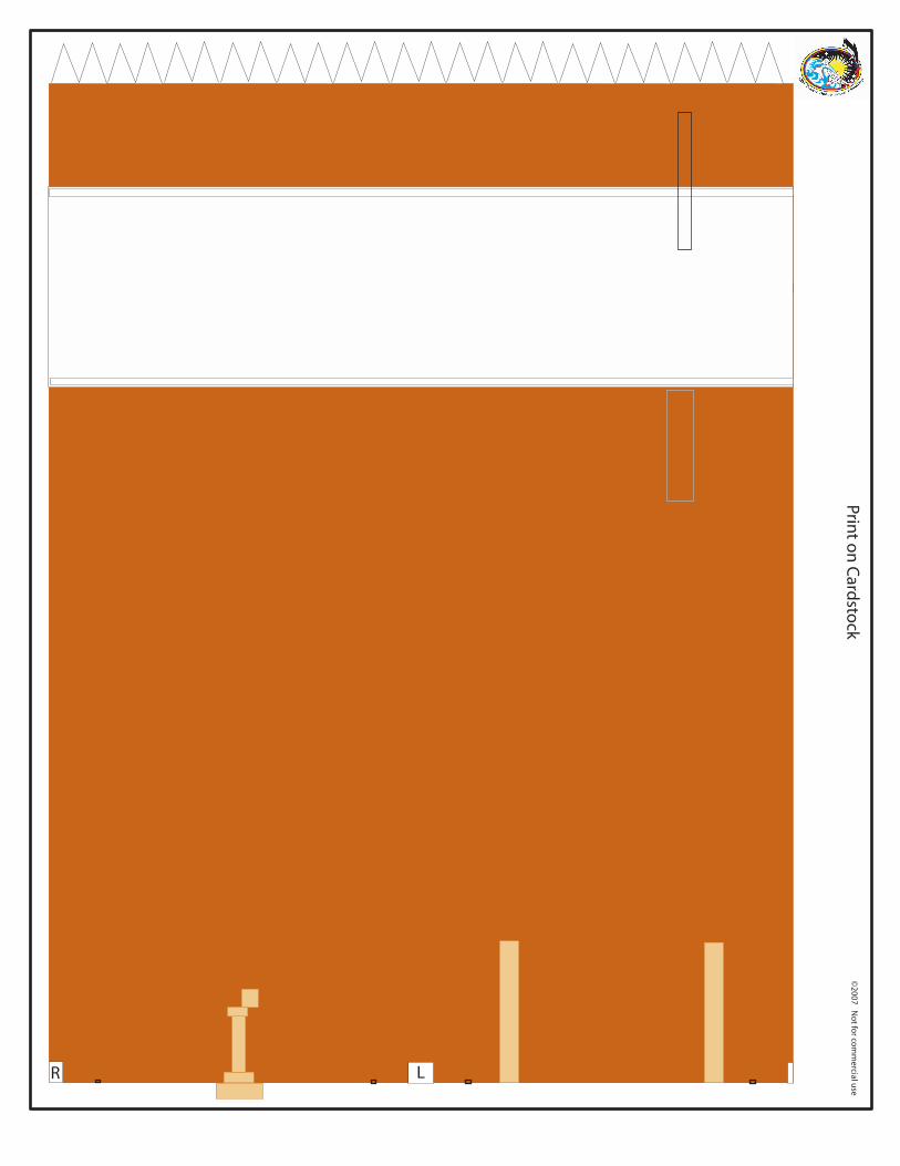
Rust color Tanks (good for 3 Stack models)
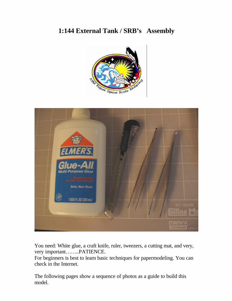
1:144 External Tank / SRB’s Assembly
You need: White glue, a craft knife, ruler, tweezers, a cutting mat, and very, very important……..PATIENCE. For beginners is best to learn basic techniques for papermodeling. You can check in the Internet. The following pages show a sequence of photos as a guide to build this model.
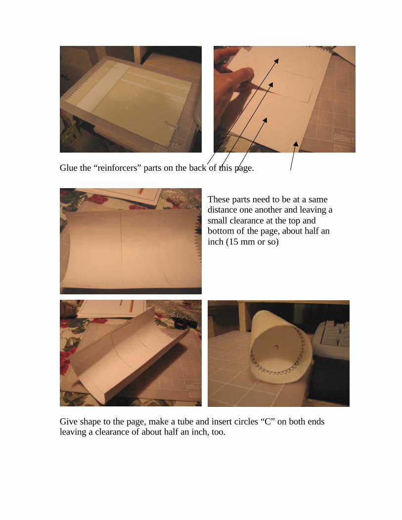
Glue the “reinforcers” parts on the back of this page.
These parts need to be at a same distance one another and leaving a small clearance at the top and bottom of the page, about half an inch (15 mm or so)
Give shape to the page, make a tube and insert circles “C” on both ends leaving a clearance of about half an inch, too.
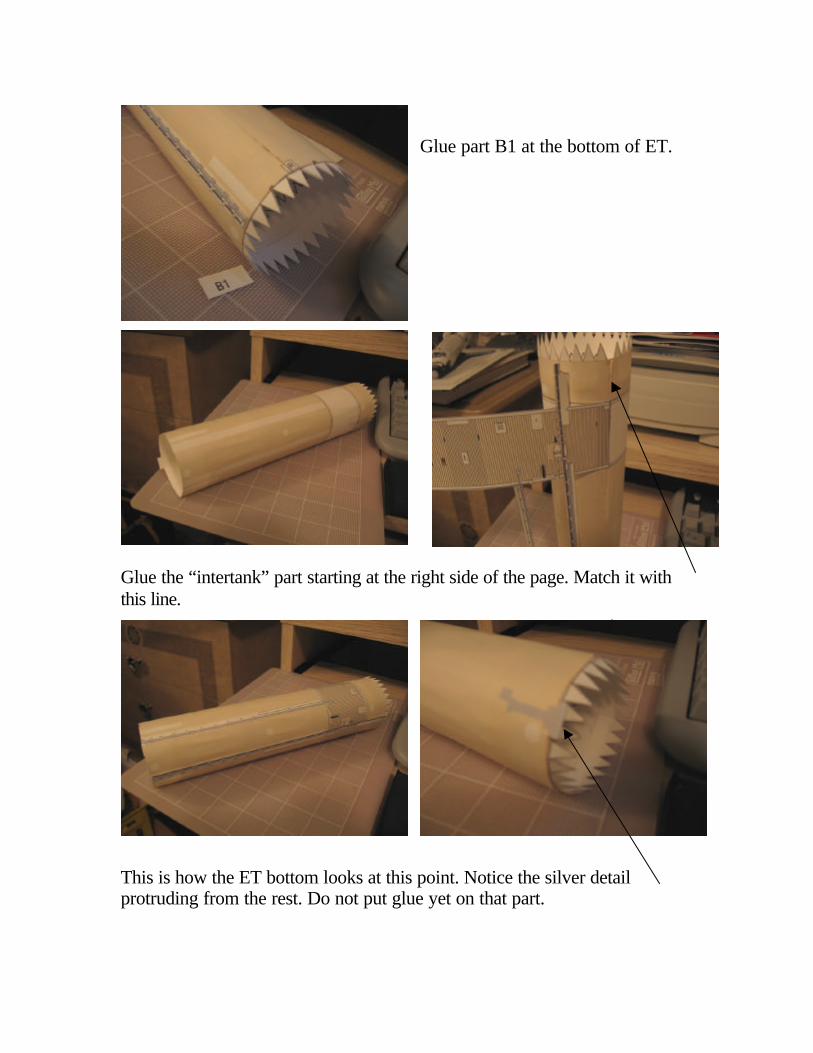
Glue part B1 at the bottom of ET.
Glue the “intertank” part starting at the right side of the page. Match it with this line.
This is how the ET bottom looks at this point. Notice the silver detail protruding from the rest. Do not put glue yet on that part.
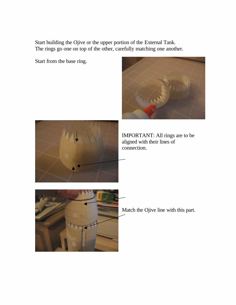
Start building the Ojive or the upper portion of the External Tank. The rings go one on top of the other, carefully matching one another. Start from the base ring.
IMPORTANT: All rings are to be aligned with their lines of connection. Match the Ojive line with this part.
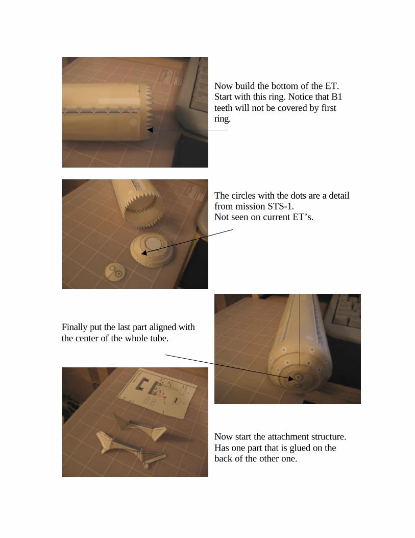
Now build the bottom of the ET. Start with this ring. Notice that B1 teeth will not be covered by first ring. The circles with the dots are a detail from mission STS-1. Not seen on current ET’s.
Finally put the last part aligned with the center of the whole tube.
Now start the attachment structure. Has one part that is glued on the back of the other one.
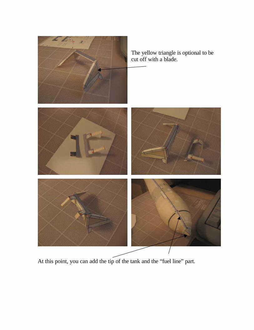
The yellow triangle is optional to be cut off with a blade.
At this point, you can add the tip of the tank and the “fuel line” part.
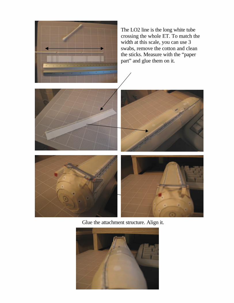
The LO2 line is the long white tube crossing the whole ET. To match the width at this scale, you can use 3 swabs, remove the cotton and clean the sticks. Measure with the “paper part” and glue them on it.
Glue the attachment structure. Align it.
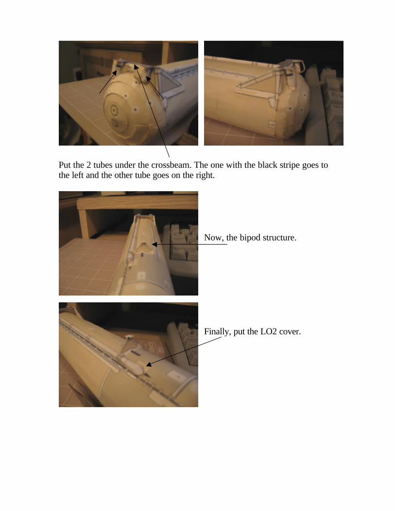
Put the 2 tubes under the crossbeam. The one with the black stripe goes to the left and the other tube goes on the right.
Now, the bipod structure. Finally, put the LO2 cover.
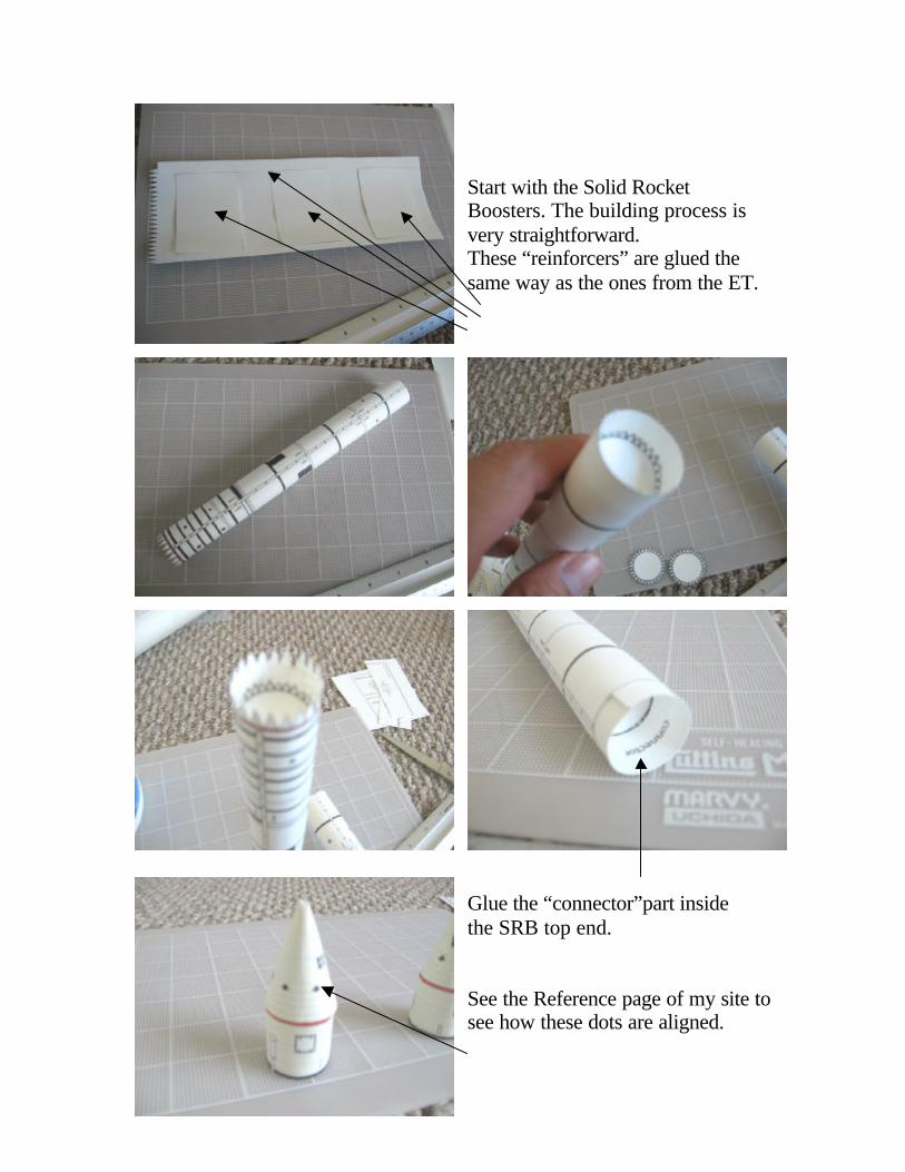
Start with the Solid Rocket Boosters. The building process is very straightforward. These “reinforcers” are glued the same way as the ones from the ET.
Glue the “connector”part inside the SRB top end. See the Reference page of my site to see how these dots are aligned.
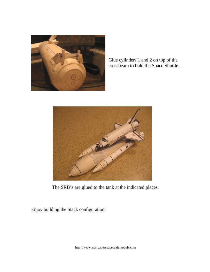
Glue cylinders 1 and 2 on top of the crossbeam to hold the Space Shuttle.
The SRB’s are glued to the tank at the indicated places. Enjoy building the Stack configuration!
http://www.axmpaperspacescalemodels.com