a chaos-based data gathering scheme using chaotic
TRANSCRIPT
A Chaos-Based Data Gathering Scheme Using Chaotic Oscillator Networks 485
A Chaos-Based Data Gathering Scheme Using Chaotic Oscillator Networks
Hidehiro Nakano, Akihide Utani, Arata Miyauchi and Hisao Yamamoto
0
A Chaos-Based Data Gathering Scheme
Using Chaotic Oscillator Networks
Hidehiro Nakano, Akihide Utani, Arata Miyauchi and Hisao YamamotoTokyo City University
Japan
1. Introduction
Recently, wireless sensor networks have been studied extensively with a great amount of inter-est. In wireless sensor networks, many wireless sensor nodes are deployed in an observationarea, and monitor status information such as temperature around them. Sensing informa-tion is transmitted to and gathered by one or more sink nodes. Each wireless sensor nodenot only transmits own sensing data but also relays the sensing data from the other wirelesssensor nodes. By such a multi-hop wireless communication, the wireless sensor networks areavailable to observation for large-scale area, and have various applications including naturalenvironmental monitoring. Since wireless sensor nodes generally operate by batteries, effi-cient data gathering schemes with saving energy consumption of each wireless sensor nodeare needed for prolonging wireless sensor network lifetime. Ant-based algorithms (Caro etal., 2004; Marwaha et al., 2002; Ohtaki et al., 2006; Subramanian et al., 1998) and cluster-basedalgorithms (Dasgupta et al., 2003; Heinzelman et al., 2000) have been proposed as routing al-gorithms. They are more scalable, efficient and robust than the other conventional routingalgorithms (Clausen & Jaquet, 2003; Johnson et al., 2003; Ogier et al., 2003; Perkins & Royer,1999). Sink node allocation schemes based on particle swarm optimization algorithms (Ku-mamoto et al., 2009; Yoshimura et al., 2009) aim to minimize total hop counts in wireless sen-sor networks and to reduce energy consumption in each wireless sensor node. Forwardingnode set selection schemes (Nagashima et al., 2009; Sasaki et al., 2009) can significantly reducethe number of transmissions of duplicate query messages as compared with original floodingschemes. Secure communication schemes considering energy savings (Li et al., 2009; Wang etal., 2009) have also been proposed. Common purpose of these studies is to prolong wirelesssensor network lifetime by saving energy consumption of each wireless sensor node.Along this line, this study focuses on control schemes for timings of transmissions and recep-tions of sensing data, proposed as a synchronization-based data gathering scheme (Wakamiya& Murata, 2005). In this scheme, each wireless sensor node has a timer characterized by anintegrate-and-fire neuron (Keener et al., 1981). Coupling the timers of wireless sensor nodeswhich can directly communicate to each other, they construct a pulse-coupled neural net-work. It is known that pulse-coupled neural networks can exhibit various synchronous andasynchronous phenomena (Catsigeras & Budelli, 1992; Mirollo & Strogatz, 1990). The con-ventional synchronization-based data gathering scheme is based on the synchronization inpulse-coupled neural networks. As synchronization is achieved, the following control for tim-ings of transmissions and receptions of sensing data is possible: wireless sensor nodes turn
21
www.intechopen.com
Sustainable Wireless Sensor Networks486
off their power supplies when they do not transmit and receive sensing data. Hence, long-term observation to target area is possible. As a hardware module, a passive wake up schemefor wireless sensor networks has also been proposed (Liang et al, 2008). In the conventionalsynchronization-based data gathering scheme, it is assumed that wireless sensor nodes do nothave any complex routing tables; they transmit and receive sensing data by only referring val-ues of hop counts to the nearest sink node. However, simple pulse-coupled neural networksconsisting of integrate-and-fire neurons can exhibit periodic synchronization only. In the con-ventional synchronization-based data gathering scheme, many duplicate sensing data can berelayed by many wireless sensor nodes. Generally, wireless sensor nodes consume a lot ofenergy in transmitting sensing data (Heinzelman et al., 2000). Also, in multiple sink wirelesssensor networks, multiple sink nodes are allocated on target area, where these are generallydistant to each other. If they are not coupled to each other by some communications, it is hardto synchronize all wireless sensor nodes. In order to prolong wireless sensor network lifetimeand realize long-term observation, more efficient data gathering schemes are needed.In the previous works, a chaos-based data gathering scheme has been proposed (Nakano et al.,2009; 2010). In the chaos-based data gathering scheme, each wireless sensor node has a timercharacterized by a chaotic spiking oscillator which generates spike-trains with chaotic inter-spike intervals (Nakano & Saito, 2002; 2004). Coupling multiple chaotic spiking oscillators, achaotic pulse-coupled neural network is constructed. Chaotic pulse-coupled neural networkscan exhibit various chaos synchronous phenomena and their breakdown phenomena. Theproposed chaos-based data gathering scheme especially applies the breakdown phenomenain chaotic pulse-coupled neural networks. In the phenomena, all chaotic spiking oscillatorsdo not exhibit perfect synchronization. However, partial synchronization on network spaceand intermittent synchronization on time-domain can be observed depending on parameters.The partial and intermittent synchronization can significantly reduce the redundant trans-missions and receptions of sensing data. In the method presented in (Nakano et al., 2009),sensing data is transmitted in the timings when transmitting wireless sensor nodes generatespike signals. In this case, lost sensing data may appear. But, it is confirmed in the numericalexperiments that high delivery ratio for sensing data can be kept. In the method presentedin (Nakano et al., 2010), sensing data is transmitted in the timings when transmitting wire-less sensor nodes accept the spike signals from the other wireless sensor nodes. In this case,it is guaranteed that all sensing data must be transmitted to sink nodes without lost sensingdata. Since all chaotic spiking oscillators do not exhibit perfect synchronization, wake up timeof each sensor node becomes longer, compared with the conventional synchronization-baseddata gathering scheme. This method does not aim to reduce energy consumption by turningoff power supply of transceivers. However, the partial and intermittent synchronization inthe chaos-based data gathering scheme can significantly reduce the total number of transmis-sions and receptions of sensing data. It can contribute to prolonging wireless sensor networklifetime. Also, the proposed chaos-based data gathering scheme can flexibly adapt not onlysingle sink wireless sensor networks but also multiple sink wireless sensor networks.This chapter consists of five sections. In Section 2, the conventional synchronization-baseddata gathering scheme is introduced, and some assumptions for wireless sensor networksin this research is explained. In Section 3, a model of the proposed chaos-based data gath-ering scheme is explained, and typical phenomena from a simple master-slave network arepresented. Then, a basic mechanism of partial and intermittent synchronization in the pro-posed chaos-based data gathering scheme is discussed. In Section 4, simulation results fortwo types of wireless sensor networks, a single sink wireless sensor network and a multiple
www.intechopen.com
A Chaos-Based Data Gathering Scheme Using Chaotic Oscillator Networks 487
sink wireless sensor network, are presented. Through simulation experiments, effectivenessof the proposed chaos-based data gathering scheme is shown, and its development potentialis discussed. In Section 5, the overall conclusions of this chapter are given and future problemsare discussed.
2. Synchronization-Based Data Gathering Scheme
First, a synchronization-based data gathering scheme presented in (Wakamiya & Murata,2005) are explained. A wireless sensor network consisting of M wireless sensor nodes andL sink nodes are considered. Each wireless sensor node Si (i = 1, · · · , M) has a timer whichcontrols timing to transmit and receive sensing data. The timer in Si is characterized by aphase φi ∈ [0, 1], an internal state xi ∈ [0, 1], a continuous and monotone function fi, a non-negative integer distance level li > 0, and an offset time δi. If each wireless sensor nodedoes not communicate to each other, dynamics of the timer in Si is described by the followingequation.
dφi(t)
dt=
1
Ti, for φi(t) < 1, (1)
φi(t+) = 0, if φi(t) = 1, (2)
where Ti denotes a period of the timer in Si. That is, if the phase φi reaches the threshold 1, Si
is said to fire, and the phase φi is reset to 0 based on Equation (2), instantaneously. The internalstate xi is determined by the continuous and monotone function fi(φi) where fi(0) = 0 andfi(1) = 1 are satisfied. The following equation is an example of the function fi.
xi = fi(φi) =1
biln(1 + (ebi − 1)φi), (3)
where bi > 0 is a parameter which controls rapidity to synchronization (Mirollo & Strogatz,1990). From Equations (1) and (3), increase of the phase φi causes increase of the internal statexi. If xi reaches the threshold 1, xi is reset to the base state 0, instantaneously.The couplings between each wireless sensor node are realized by the following manner. Let Sj
be one of the neighbor wireless sensor nodes allocated in the radio range of a wireless sensornode Si. The wireless sensor node Si has a nonnegative integer distance level li characterizedby the number of hop counts from the nearest sink node. The wireless sensor node Si transmitsa stimulus signal with the own distance level li. If Sj receives the signal from Si, Sj comparesthe received distance level li with the own distance level lj. If lj > li is satisfied, Sj is said tobe stimulated by Si, and the phase and internal state of Sj change as follows:
xj(t+) = B(xj(t) + ε j), (4)
B(x) =
x, if 0 ≤ x ≤ 1,0, if x < 0,1, if x > 1,
(5)
φj(t+) = f−1
j (xj(t+)), (6)
where ε j denotes a strength of the stimulus. After Sj is stimulated, Sj does not respond to allstimulus signals from the neighbor wireless sensor nodes during an offset time δj. That is,each wireless sensor node has a refractory period corresponding to the offset time.
www.intechopen.com

Sustainable Wireless Sensor Networks488
),( ii xϕ),( ii x′′ϕ
iδ
jε
),( jj xϕ
1
1
t
0
0
Fig. 1. Time-domain waveforms of internal states xi and xj (lj > li).
∞∞
∞
∞
∞
∞
0
∞
11
∞
∞
∞
∞
0
∞
11
2
2
2
∞
0
∞
Fig. 2. Propagation of stimulus signals and update of distance levels.
The stimulus signals are transmitted by the following manner. A wireless sensor node Si
broadcasts stimulus signals offset time δi earlier than the own firing time. That is, Si broad-casts the stimulus signals if the following virtual internal state x′i considered the offset time δi
reaches the threshold 1.φ′
i = φi + δi (mod 1), (7)
x′i = fi(φ′
i). (8)
Fig. 1 shows time-domain waveforms of internal states xi and xj, where lj > li.Distance levels of each wireless sensor node are adjusted as shown in Fig. 2. Initially, distancelevels of each wireless sensor node are set to sufficiently large values, and that of the sinknode is set to 0. A sink node broadcasts “level 0” as a beacon signal. Then, each wireless
11
2
2
2
3
0
3
11
2
2
2
3
0
3
11
2
2
2
3
0
3
Fig. 3. Transmission of sensing data based on distance levels.
iil
1ij ll
t
t
stimulus ontransmissi
j
stimulus ontransmissi
stimulus ontransmissi
nodesink
1ix 1ix
1jx 1jx
www.intechopen.com
A Chaos-Based Data Gathering Scheme Using Chaotic Oscillator Networks 489
),( ii x),( ii x
i
j
),( jj x
1
1
t
0
0
01
1 01
1
2
2
20
11
2
2
2
3
0
3
11
2
2
2
3
0
3
11
2
2
2
3
0
3
iδil
1+= ij ll
t
t
stimulus ontransmissi
jδ
stimulus ontransmissi
stimulus ontransmissi
nodesink
1=′ix 1=ix
1=′jx 1=jx
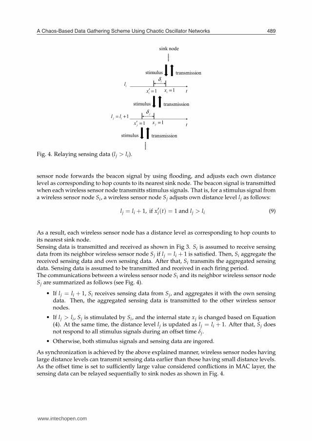
Fig. 4. Relaying sensing data (lj > li).
sensor node forwards the beacon signal by using flooding, and adjusts each own distancelevel as corresponding to hop counts to its nearest sink node. The beacon signal is transmittedwhen each wireless sensor node transmitts stimulus signals. That is, for a stimulus signal froma wireless sensor node Si, a wireless sensor node Sj adjusts own distance level lj as follows:
lj = li + 1, if x′i(t) = 1 and lj > li (9)
As a result, each wireless sensor node has a distance level as corresponding to hop counts toits nearest sink node.Sensing data is transmitted and received as shown in Fig 3. Si is assumed to receive sensingdata from its neighbor wireless sensor node Sj if lj = li + 1 is satisfied. Then, Si aggregate thereceived sensing data and own sensing data. After that, Si transmits the aggregated sensingdata. Sensing data is assumed to be transmitted and received in each firing period.The communications between a wireless sensor node Si and its neighbor wireless sensor nodeSj are summarized as follows (see Fig. 4).
• If lj = li + 1, Si receives sensing data from Sj, and aggregates it with the own sensingdata. Then, the aggregated sensing data is transmitted to the other wireless sensornodes.
• If lj > li, Sj is stimulated by Si, and the internal state xj is changed based on Equation(4). At the same time, the distance level lj is updated as lj = li + 1. After that, Sj doesnot respond to all stimulus signals during an offset time δj.
• Otherwise, both stimulus signals and sensing data are ingored.
As synchronization is achieved by the above explained manner, wireless sensor nodes havinglarge distance levels can transmit sensing data earlier than those having small distance levels.As the offset time is set to sufficiently large value considered conflictions in MAC layer, thesensing data can be relayed sequentially to sink nodes as shown in Fig. 4.
www.intechopen.com
Sustainable Wireless Sensor Networks490
3. Chaos-Based Data Gathering Scheme
In this section, a chaos-based data gathering scheme using a chaotic pulse-coupled neuralnetwork presented in (Nakano et al., 2009; 2010) is explained. As same as synchronization-based data gathering scheme, a wireless sensor network consisting of M wireless sensor nodesand L sink nodes are considered. Each wireless sensor node Si (i = 1, · · · , M) has a timerwhich controls timing to transmit and receive sensing data. The timer in Si is characterizedby an oscillator having two internal state variables xi and yi, a non-negative integer distancelevel li, and an offset time δi. Basic dynamics of the timer in Si is described by the followingequation.
d
dt
[
xi(t)yi(t)
]
=
[
∆i ωi
−ωi ∆i
] [
xi(t)yi(t)
]
, for xi(t) < 1 ∧∧
j
(
x′j(t) < 1)
(10)
[
xi(t+)
yi(t+)
]
=
[
qi
yi(t)− pi(xi(t)− qi)
]
, if xi(t) = 1 (11)
[
xi(t+)
yi(t+)
]
=
[
ai
yi(t)− pi(xi(t)− ai)
]
, if∨
j
(
x′j(t) = 1)
(12)
where ∆i is a damping, ωi is a self-running angular frequency, pi is a slope in firing, qi isa base sate for self-firing and ai is a base state for compulsory-firing. j denotes an index of aneighbor wireless sensor node Sj such that lj < li. x′j(t) is a virtual internal state variable of Sj
considered an offset time δj such that
x′j(t) = xj(t + δj) (13)
If the internal state variable xi reaches the threshold 1, Si exhibits self-firing, and the internalstate (xi, yi) is reset to the base state based on Equation (11). If a virtual internal state variablex′j reaches the threshold 1, Si exhibits compulsory-firing, and the internal state (xi, yi) is reset to
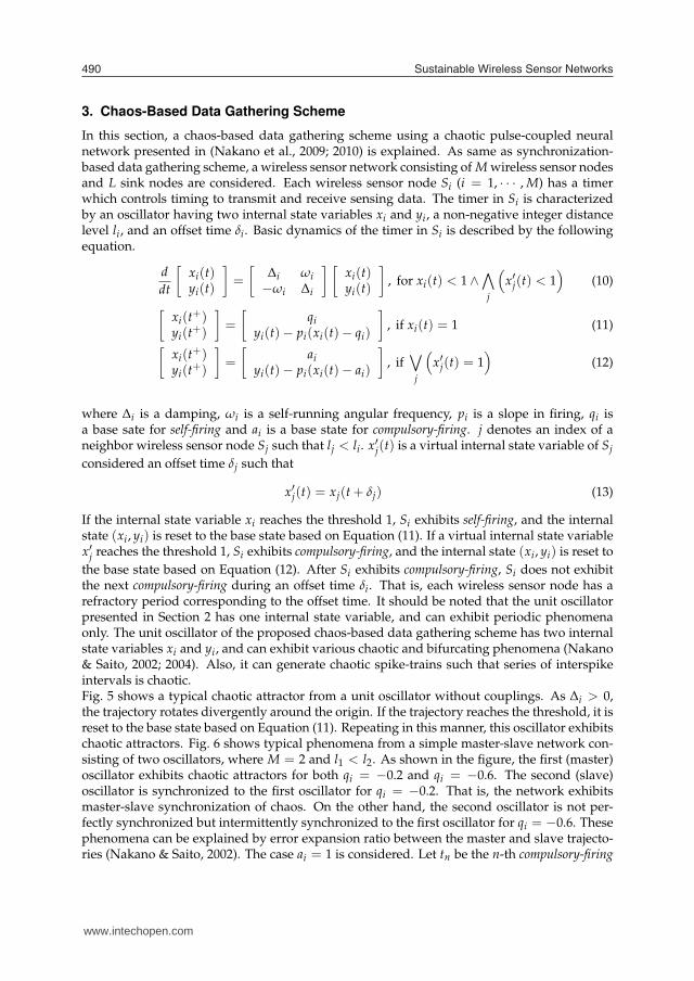
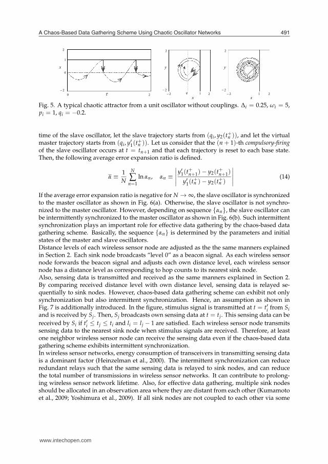
the base state based on Equation (12). After Si exhibits compulsory-firing, Si does not exhibitthe next compulsory-firing during an offset time δi. That is, each wireless sensor node has arefractory period corresponding to the offset time. It should be noted that the unit oscillatorpresented in Section 2 has one internal state variable, and can exhibit periodic phenomenaonly. The unit oscillator of the proposed chaos-based data gathering scheme has two internalstate variables xi and yi, and can exhibit various chaotic and bifurcating phenomena (Nakano& Saito, 2002; 2004). Also, it can generate chaotic spike-trains such that series of interspikeintervals is chaotic.Fig. 5 shows a typical chaotic attractor from a unit oscillator without couplings. As ∆i > 0,the trajectory rotates divergently around the origin. If the trajectory reaches the threshold, it isreset to the base state based on Equation (11). Repeating in this manner, this oscillator exhibitschaotic attractors. Fig. 6 shows typical phenomena from a simple master-slave network con-sisting of two oscillators, where M = 2 and l1 < l2. As shown in the figure, the first (master)oscillator exhibits chaotic attractors for both qi = −0.2 and qi = −0.6. The second (slave)oscillator is synchronized to the first oscillator for qi = −0.2. That is, the network exhibitsmaster-slave synchronization of chaos. On the other hand, the second oscillator is not per-fectly synchronized but intermittently synchronized to the first oscillator for qi = −0.6. Thesephenomena can be explained by error expansion ratio between the master and slave trajecto-ries (Nakano & Saito, 2002). The case ai = 1 is considered. Let tn be the n-th compulsory-firing
y
x
x
22
2
22
20 2
y
x2
22
2
q 1 1
1
q
www.intechopen.com
A Chaos-Based Data Gathering Scheme Using Chaotic Oscillator Networks 491
y
x
x
τ 2−2−
2
22
2−
0 2
y
x2−
2−2
2
q 1 1
1
q
Fig. 5. A typical chaotic attractor from a unit oscillator without couplings. ∆i = 0.25, ωi = 5,pi = 1, qi = −0.2.
time of the slave oscillator, let the slave trajectory starts from (qi, y2(t+n )), and let the virtual
master trajectory starts from (qi, y′1(t+n )). Let us consider that the (n + 1)-th compulsory-firing
of the slave oscillator occurs at t = tn+1 and that each trajectory is reset to each base state.Then, the following average error expansion ratio is defined.
α ≡1
N
N
∑n=1
ln αn, αn ≡
∣
∣
∣
∣
∣
y′1(t+n+1)− y2(t
+n+1)
y′1(t+n )− y2(t
+n )
∣
∣
∣
∣
∣
(14)
If the average error expansion ratio is negative for N → ∞, the slave oscillator is synchronizedto the master oscillator as shown in Fig. 6(a). Otherwise, the slave oscillator is not synchro-nized to the master oscillator. However, depending on sequence {αn}, the slave oscillator canbe intermittently synchronized to the master oscillator as shown in Fig. 6(b). Such intermittentsynchronization plays an important role for effective data gathering by the chaos-based datagathering scheme. Basically, the sequence {αn} is determined by the parameters and initialstates of the master and slave oscillators.Distance levels of each wireless sensor node are adjusted as the the same manners explainedin Section 2. Each sink node broadcasts “level 0” as a beacon signal. As each wireless sensornode forwards the beacon signal and adjusts each own distance level, each wireless sensornode has a distance level as corresponding to hop counts to its nearest sink node.Also, sensing data is transmitted and received as the same manners explained in Section 2.By comparing received distance level with own distance level, sensing data is relayed se-quentially to sink nodes. However, chaos-based data gathering scheme can exhibit not onlysynchronization but also intermittent synchronization. Hence, an assumption as shown inFig. 7 is additionally introduced. In the figure, stimulus signal is transmitted at t = t′i from Si
and is received by Sj. Then, Sj broadcasts own sensing data at t = tj. This sensing data can be
received by Si if t′i ≤ tj ≤ ti and li = lj − 1 are satisfied. Each wireless sensor node transmitssensing data to the nearest sink node when stimulus signals are received. Therefore, at leastone neighbor wireless sensor node can receive the sensing data even if the chaos-based datagathering scheme exhibits intermittent synchronization.In wireless sensor networks, energy consumption of transceivers in transmitting sensing datais a dominant factor (Heinzelman et al., 2000). The intermittent synchronization can reduceredundant relays such that the same sensing data is relayed to sink nodes, and can reducethe total number of transmissions in wireless sensor networks. It can contribute to prolong-ing wireless sensor network lifetime. Also, for effective data gathering, multiple sink nodesshould be allocated in an observation area where they are distant from each other (Kumamotoet al., 2009; Yoshimura et al., 2009). If all sink nodes are not coupled to each other via some
www.intechopen.com
Sustainable Wireless Sensor Networks492
2− 2
2
1x′
1y′
2− 2
2
2x
2y
2− 2
2
1x′
2x
(a)
2− 2
2
1x′
1y′
2− 2
2
2x
2y
2− 2
2
1x′
2x
(b)
Fig. 6. Typical phenomena from a master-slave chaotic pulse-coupled neural network. Left:Master attractors. Center: Slave attractors. Right: Phase relationships. ∆i = 0.25, ωi = 5,pi = 1, ai = 1, δi = 0 (i = 1, 2). (a) Synchronization of chaos: qi = −0.2 (i = 1, 2). (b)Intermittent synchronization: qi = −0.6 (i = 1, 2).
communications, it is hard to synchronize all wireless sensor nodes. Because, oscillators with-out couplings never synchronize to each other. The intermittent synchronization can flexiblyadapt various wireless sensor networks not only with a single sink node but also with multi-ple sink nodes. These advantages can be confirmed by the simulation experiments in the nextsection.The chaos-based data gathering scheme is based on the conventional synchronization-baseddata gathering scheme, and does not use any complex protocols using routing tables. There-fore, this method can easily control transmitting and receiving wireless sensor nodes and canflexibly adapt dynamical changes of network topologies. In the conventional synchronization-based data gathering scheme, power supply of transceivers can be turned off when wirelesssensor nodes do not transmit or relay sensing data. However, many wireless sensor nodes canrelay the same sensing data. The chaos-based data gathering scheme does not aim to reduceenergy consumption by turning off power supply of transceivers. However, partial and inter-mittent synchronization in the chaos-based data gathering scheme can significantly reduce thenumber of transmitting and receiving sensing data. In addition, this method can guaranteethat sensing data from all wireless sensor nodes must be transmitted to sink nodes withoutloss.
i
1ix 1ix
1jx 1jx
t
t
it it
jt jt
stimulus ontransmissi
j
il
1ij ll
30 30
30
www.intechopen.com
A Chaos-Based Data Gathering Scheme Using Chaotic Oscillator Networks 493
2 2
2
1x
1y
2 2
2
2x
2y
2 2
2
1x
2x
2 2
2
1x
1y
2 2
2
2x
2y
2 2
2
1x
2x
iδ1=′ix 1=ix
1=′jx 1=jx
t
t
it′ it
jt′ jt
stimulus ontransmissi
jδ
il
1+= ij ll
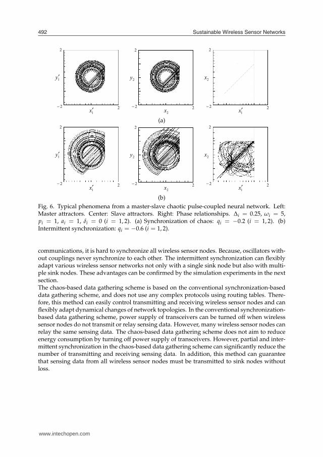
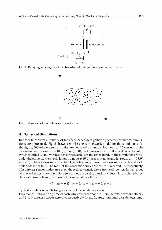
Fig. 7. Relaying sensing data in a chaos-based data gathering scheme (lj > li).
30− 30
30
Fig. 8. A model of a wireless sensor network.
4. Numerical Simulations
In order to confirm effectivity of the chaos-based data gathering scheme, numerical simula-tions are performed. Fig. 8 shows a wireless sensor network model for the simulations. Inthe figure, 300 wireless sensor nodes are deployed at random locations on 12 concentric cir-cles whose centers are (−15, 0), (0, 0) or (15, 0), and 3 sink nodes are allocated on each center,which is called 3-sink wireless sensor network. On the other hand, in the simulations for 1-sink wireless sensor network, let only a node at (0, 0) be a sink node and let nodes at (−15, 0)and (15, 0) be wireless sensor nodes. The radio range of each wireless sensor node and eachsink node is set to 5. The radii of the concentric circles are set to 3, 6, 9 and 12, respectively.10n wireless sensor nodes are set on the n-th concentric circle from each center. Initial valuesof internal states in each wireless sensor node are set to random values. In the chaos-baseddata gathering scheme, the parameters are fixed as follows.
∀i, ∆i = 0.25, ωi = 5, pi = 1, δi = 0.2, ai = 1.
Typical simulation results for qi as a control parameter are shown.Figs. 9 and 10 show firing time of each wireless sensor node in 1-sink wireless sensor networkand 3-sink wireless sensor network, respectively. In the figures, horizontal axis denotes time,
www.intechopen.com
Sustainable Wireless Sensor Networks494
20
300
0t
iS
(a)
20
300
0t
iS
(b)
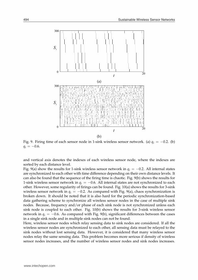
Fig. 9. Firing time of each sensor node in 1-sink wireless sensor network. (a) qi = −0.2. (b)qi = −0.6.
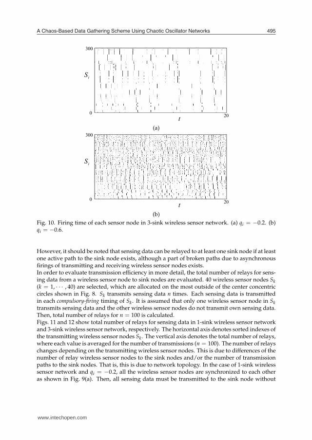
and vertical axis denotes the indexes of each wireless sensor node, where the indexes aresorted by each distance level.Fig. 9(a) show the results for 1-sink wireless sensor network in qi = −0.2. All internal statesare synchronized to each other with time difference depending on their own distance levels. Itcan also be found that the sequence of the firing time is chaotic. Fig. 9(b) shows the results for1-sink wireless sensor network in qi = −0.6. All internal states are not synchronized to eachother. However, some regularity of firings can be found. Fig. 10(a) shows the results for 3-sinkwireless sensor network in qi = −0.2. As compared with Fig. 9(a), chaos synchronization isbroken down. It should be noted that it is also hard for the periodic synchronization-baseddata gathering scheme to synchronize all wireless sensor nodes in the case of multiple sinknodes. Because, frequency and/or phase of each sink node is not synchronized unless eachsink node is coupled to each other. Fig. 10(b) shows the results for 3-sink wireless sensornetwork in qi = −0.6. As compared with Fig. 9(b), significant differences between the casesin a single sink node and in multiple sink nodes can not be found.Here, wireless sensor nodes which relay sensing data to sink nodes are considered. If all thewireless sensor nodes are synchronized to each other, all sensing data must be relayed to thesink nodes without lost sensing data. However, it is considered that many wireless sensornodes relay the same sensing data. This problem becomes more serious if density of wirelesssensor nodes increases, and the number of wireless sensor nodes and sink nodes increases.
20
300
0t
iS
20
300
0t
iS
www.intechopen.com
A Chaos-Based Data Gathering Scheme Using Chaotic Oscillator Networks 495
20
300
0t
iS
20
300
0t
iS
20
300
0t
iS
(a)
20
300
0t
iS
(b)
Fig. 10. Firing time of each sensor node in 3-sink wireless sensor network. (a) qi = −0.2. (b)qi = −0.6.
However, it should be noted that sensing data can be relayed to at least one sink node if at leastone active path to the sink node exists, although a part of broken paths due to asynchronousfirings of transmitting and receiving wireless sensor nodes exists.In order to evaluate transmission efficiency in more detail, the total number of relays for sens-ing data from a wireless sensor node to sink nodes are evaluated. 40 wireless sensor nodes Sk
(k = 1, · · · , 40) are selected, which are allocated on the most outside of the center concentriccircles shown in Fig. 8. Sk transmits sensing data n times. Each sensing data is transmittedin each compulsory-firing timing of Sk. It is assumed that only one wireless sensor node in Sk
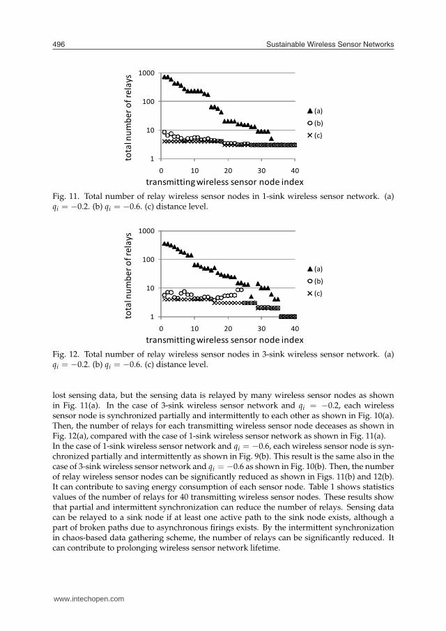
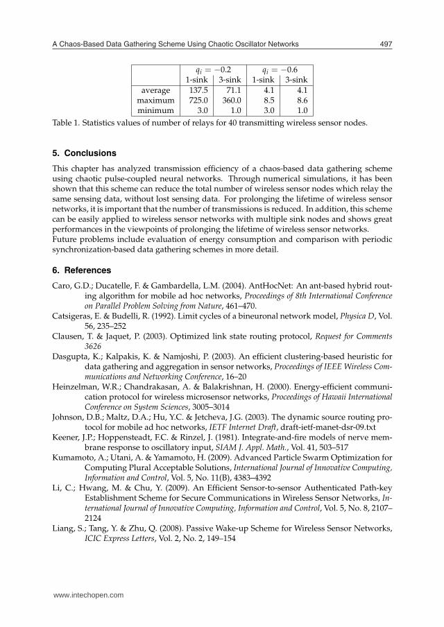
transmits sensing data and the other wireless sensor nodes do not transmit own sensing data.Then, total number of relays for n = 100 is calculated.Figs. 11 and 12 show total number of relays for sensing data in 1-sink wireless sensor networkand 3-sink wireless sensor network, respectively. The horizontal axis denotes sorted indexes ofthe transmitting wireless sensor nodes Sk. The vertical axis denotes the total number of relays,where each value is averaged for the number of transmissions (n = 100). The number of relayschanges depending on the transmitting wireless sensor nodes. This is due to differences of thenumber of relay wireless sensor nodes to the sink nodes and/or the number of transmissionpaths to the sink nodes. That is, this is due to network topology. In the case of 1-sink wirelesssensor network and qi = −0.2, all the wireless sensor nodes are synchronized to each otheras shown in Fig. 9(a). Then, all sensing data must be transmitted to the sink node without
www.intechopen.com
Sustainable Wireless Sensor Networks496
tota
l nu
mb
er
of
rela
ys
1
10
100
1000
0 10 20 30 40
(a)
(b)
(c)
transmitting wireless sensor node index
Fig. 11. Total number of relay wireless sensor nodes in 1-sink wireless sensor network. (a)qi = −0.2. (b) qi = −0.6. (c) distance level.
transmitting wireless sensor node index
tota
l nu
mb
er
of
rela
ys
1
10
100
1000
0 10 20 30 40
(a)
(b)
(c)
Fig. 12. Total number of relay wireless sensor nodes in 3-sink wireless sensor network. (a)qi = −0.2. (b) qi = −0.6. (c) distance level.
lost sensing data, but the sensing data is relayed by many wireless sensor nodes as shownin Fig. 11(a). In the case of 3-sink wireless sensor network and qi = −0.2, each wirelesssensor node is synchronized partially and intermittently to each other as shown in Fig. 10(a).Then, the number of relays for each transmitting wireless sensor node deceases as shown inFig. 12(a), compared with the case of 1-sink wireless sensor network as shown in Fig. 11(a).In the case of 1-sink wireless sensor network and qi = −0.6, each wireless sensor node is syn-chronized partially and intermittently as shown in Fig. 9(b). This result is the same also in thecase of 3-sink wireless sensor network and qi = −0.6 as shown in Fig. 10(b). Then, the numberof relay wireless sensor nodes can be significantly reduced as shown in Figs. 11(b) and 12(b).It can contribute to saving energy consumption of each sensor node. Table 1 shows statisticsvalues of the number of relays for 40 transmitting wireless sensor nodes. These results showthat partial and intermittent synchronization can reduce the number of relays. Sensing datacan be relayed to a sink node if at least one active path to the sink node exists, although apart of broken paths due to asynchronous firings exists. By the intermittent synchronizationin chaos-based data gathering scheme, the number of relays can be significantly reduced. Itcan contribute to prolonging wireless sensor network lifetime.
www.intechopen.com
A Chaos-Based Data Gathering Scheme Using Chaotic Oscillator Networks 497
qi = −0.2 qi = −0.61-sink 3-sink 1-sink 3-sink
average 137.5 71.1 4.1 4.1maximum 725.0 360.0 8.5 8.6minimum 3.0 1.0 3.0 1.0
Table 1. Statistics values of number of relays for 40 transmitting wireless sensor nodes.
5. Conclusions
This chapter has analyzed transmission efficiency of a chaos-based data gathering schemeusing chaotic pulse-coupled neural networks. Through numerical simulations, it has beenshown that this scheme can reduce the total number of wireless sensor nodes which relay thesame sensing data, without lost sensing data. For prolonging the lifetime of wireless sensornetworks, it is important that the number of transmissions is reduced. In addition, this schemecan be easily applied to wireless sensor networks with multiple sink nodes and shows greatperformances in the viewpoints of prolonging the lifetime of wireless sensor networks.Future problems include evaluation of energy consumption and comparison with periodicsynchronization-based data gathering schemes in more detail.
6. References
Caro, G.D.; Ducatelle, F. & Gambardella, L.M. (2004). AntHocNet: An ant-based hybrid rout-ing algorithm for mobile ad hoc networks, Proceedings of 8th International Conferenceon Parallel Problem Solving from Nature, 461–470.
Catsigeras, E. & Budelli, R. (1992). Limit cycles of a bineuronal network model, Physica D, Vol.56, 235–252
Clausen, T. & Jaquet, P. (2003). Optimized link state routing protocol, Request for Comments3626
Dasgupta, K.; Kalpakis, K. & Namjoshi, P. (2003). An efficient clustering-based heuristic fordata gathering and aggregation in sensor networks, Proceedings of IEEE Wireless Com-munications and Networking Conference, 16–20
Heinzelman, W.R.; Chandrakasan, A. & Balakrishnan, H. (2000). Energy-efficient communi-cation protocol for wireless microsensor networks, Proceedings of Hawaii InternationalConference on System Sciences, 3005–3014
Johnson, D.B.; Maltz, D.A.; Hu, Y.C. & Jetcheva, J.G. (2003). The dynamic source routing pro-tocol for mobile ad hoc networks, IETF Internet Draft, draft-ietf-manet-dsr-09.txt
Keener, J.P.; Hoppensteadt, F.C. & Rinzel, J. (1981). Integrate-and-fire models of nerve mem-brane response to oscillatory input, SIAM J. Appl. Math., Vol. 41, 503–517
Kumamoto, A.; Utani, A. & Yamamoto, H. (2009). Advanced Particle Swarm Optimization forComputing Plural Acceptable Solutions, International Journal of Innovative Computing,Information and Control, Vol. 5, No. 11(B), 4383–4392
Li, C.; Hwang, M. & Chu, Y. (2009). An Efficient Sensor-to-sensor Authenticated Path-keyEstablishment Scheme for Secure Communications in Wireless Sensor Networks, In-ternational Journal of Innovative Computing, Information and Control, Vol. 5, No. 8, 2107–2124
Liang, S.; Tang, Y. & Zhu, Q. (2008). Passive Wake-up Scheme for Wireless Sensor Networks,ICIC Express Letters, Vol. 2, No. 2, 149–154
www.intechopen.com
Sustainable Wireless Sensor Networks498
Marwaha, S.; Tham, C.K. & Srinivasan, D. (2002). A novel routing protocol using mobileagents and reactive route discovery for ad hoc wireless networks, Proceedings of IEEEInternational Conference on Networks, 311–316
Mirollo, R.E. & Strogatz, S.H. (1990). Synchronization of pulse-coupled biological oscillators,SIAM J. Appl. Math., Vol. 50, 1645–1662
Nagashima, J.; Utani, A. & Yamamoto, H. (2009). Efficient Flooding Method Using DiscreteParticle Swarm Optimization for Long-Term Operation of Sensor Networks, ICICExpress Letters, Vol. 3, No. 3(B), 833–840
Nakano, H. & Saito, T. (2002). Basic dynamics from a pulse-coupled network of autonomousintegrate-and-fire chaotic circuits, IEEE Transactions on Neural Networks, Vol. 13, No.1, 92–100
Nakano, H. & Saito, T. (2004). Grouping Synchronization in a Pulse-Coupled Network ofChaotic Spiking Oscillators, IEEE Transactions on Neural Networks, Vol. 15, No. 5,1018–1026
Nakano, H.; Utani, A.; Miyauchi, A. & Yamamoto, H. (2009). Data Gathering Scheme UsingChaotic Pulse-Coupled Neural Networks for Wireless Sensor Networks. IEICE Trans-actions on Fundamentals, Vol. E92-A, No. 2, 459–466
Nakano, H.; Utani, A.; Miyauchi, A. & Yamamoto, H. (2010). Prolonging Lifetime of Multiple-Sink Wireless Sensor Networks Using Chaos-Based Data Gathering Scheme, Proceed-ings of ICUFN, 12–16
Ogier, R.; Lewis, M. & Templin, F. (2003). Topology dissemination based on reverse-path for-warding (TBRPF), IETF Internet Draft, draft-ietf-manet-tbrpf-10.txt
Ohtaki, Y.; Wakamiya, N.; Murata, M. & Imase, M. (2006). Scalable and efficient ant-basedrouting algorithm for ad-hoc networks, IEICE Transactions on Communications, Vol.E89-B, No. 4, 1231–1238
Perkins, C.E. & Royer, E.M. (1999). Ad hoc on-demand distance vector routing, Proceedings of2nd IEEE Workshop on Mobile Computing Systems and Applications, 90–100
Sasaki, T.; Nakano, H.; Utani, A.; Miyauchi, A. & Yamamoto, H. (2009). An Efficient FloodingScheme Using Chaotic Neural Networks in Wireless Sensor Networks, Proceedings ofNOLTA, 523–526
Subramanian, D.; Druschel, P. & Chen, J. (1998). Ants and reinforcement learning: A casestudy in routing in dynamic networks, Technical Report TR96-259, Rice University
Wakamiya, N. & Murata, M. (2005). synchronization-based data gathering scheme for sensornetworks, IEICE Trans Commun, Vol. E88-B, No. 3, 873–881
Wang, C.; Hong, T.; Horng, G. & Wang, W. (2009). A GA-based Key-management Scheme inHierarchical Wireless Sensor Networks, International Journal of Innovative Computing,Information and Control, Vol. 5, No. 12(A), 4693–4702
Yoshimura, M.; Nakano, H.; Utani, A.; Miyauchi A. & Yamamoto, H. (2009). An EffectiveAllocation Scheme for Sink Nodes in Wireless Sensor Networks Using SuppressionPSO, ICIC Express Letters, Vol. 3, No. 3(A), 519–524
www.intechopen.com

Sustainable Wireless Sensor NetworksEdited by Yen Kheng Tan
ISBN 978-953-307-297-5Hard cover, 574 pagesPublisher InTechPublished online 14, December, 2010Published in print edition December, 2010
InTech EuropeUniversity Campus STeP Ri Slavka Krautzeka 83/A 51000 Rijeka, Croatia Phone: +385 (51) 770 447 Fax: +385 (51) 686 166www.intechopen.com
InTech ChinaUnit 405, Office Block, Hotel Equatorial Shanghai No.65, Yan An Road (West), Shanghai, 200040, China
Phone: +86-21-62489820 Fax: +86-21-62489821
Wireless Sensor Networks came into prominence around the start of this millennium motivated by theomnipresent scenario of small-sized sensors with limited power deployed in large numbers over an area tomonitor different phenomenon. The sole motivation of a large portion of research efforts has been to maximizethe lifetime of the network, where network lifetime is typically measured from the instant of deployment to thepoint when one of the nodes has expended its limited power source and becomes in-operational –commonly referred as first node failure. Over the years, research has increasingly adopted ideas from wirelesscommunications as well as embedded systems development in order to move this technology closer to realisticdeployment scenarios. In such a rich research area as wireless sensor networks, it is difficult if not impossibleto provide a comprehensive coverage of all relevant aspects. In this book, we hope to give the reader with asnapshot of some aspects of wireless sensor networks research that provides both a high level overview aswell as detailed discussion on specific areas.
How to referenceIn order to correctly reference this scholarly work, feel free to copy and paste the following:
Akihide Utani, Arata Miyauchi, Hisao Yamamoto and Hidehiro Nakano (2010). A Chaos-Based Data GatheringScheme Using Chaotic Oscillator Networks, Sustainable Wireless Sensor Networks, Yen Kheng Tan (Ed.),ISBN: 978-953-307-297-5, InTech, Available from: http://www.intechopen.com/books/sustainable-wireless-sensor-networks/a-chaos-based-data-gathering-scheme-using-chaotic-oscillator-networks

© 2010 The Author(s). Licensee IntechOpen. This chapter is distributedunder the terms of the Creative Commons Attribution-NonCommercial-ShareAlike-3.0 License, which permits use, distribution and reproduction fornon-commercial purposes, provided the original is properly cited andderivative works building on this content are distributed under the samelicense.