acs 611 - bosch tehničke obuke · acs 611 de originalbetriebsanleitung klimaservicegerät en...
TRANSCRIPT
ACS 611
de OriginalbetriebsanleitungKlimaservicegerät
en Original instructionsA/C service-unit
fr Notice originaleAppareil de SAV pour climatiseur
es Manual originalAparato de servicios de aireacondicionado
it Istruzioni originaliAttrezzatura per assistenzaclimatizzatore
sv Bruksanvisning i originalA/C serviceenhet
nl Oorspronkelijke gebruiksaanwijzingAirco-onderhoudsapparaat
pt Manual originalAparelho de manutenção de sistemasde ar condicionado
fi Alkuperäiset ohjeetA/C huoltolaite
da Original brugsanvisningA/C tjenesten Unit
no Original driftsinstruksA/C tjenesten Unit
pl Oryginalna instrukcja eksploatacjiUrządzenie do obsługi układuklimatyzacji
cs Původní návod k používáníPřístroj na servis klimatizací vozidel
tr Orijinal işletme talimatıA/C servis ünitesi
ru Оригинальное руководство по эксплуатацииПодготовка к обслуживанию


S P00 D00 002 2013-04-10| Robert Bosch GmbH
32 | ACS 611 | en
1. Symbols used 341.1 In the documentation 34
1.1.1 Warning notices - Structure and meaning 34
1.1.2 Symbols in this documentation 341.2 On the product 34
2. Important notes 342.1 User group 342.2 Agreement 342.3 Obligation of contractor 352.4 Safety regulations 362.5 Safety devices 37
3. Product description 383.1 Application 383.2 Delivery specification 383.3 Overview on software texts 383.4 Description of unit 39
3.4.1 Selection and function keys 403.4.2 Input keys 413.4.3 Printer 413.4.4 Service flap 413.4.5 Scales for
refrigerant, fresh oil and used oil 413.4.6 Service hose and service quick-release
coupling 423.4.7 Locking brakes 423.4.8 Power cord 423.4.9 Master switch 42
3.5 Description of function 42
4. Program structure 434.1 Calibration and tare 434.2 Settings 434.3 Repair 434.4 Vehicle and customer data 434.5 Menu 434.6 Manual mode 434.7 Automatic mode 434.8 Flush (optional) 434.9 Enter 43
5. Initial commissioning 445.1 Removing transportation packaging 445.2 Switching on the ACS 611 445.3 Required settings 44
5.3.1 Setting the language 445.3.2 Setting the date and time 445.3.3 Set workshop data 455.3.4 Enter serial number 45
5.4 Internal Refrigerant cylinder 455.4.1 Checking type of connection of
external refrigerant cylinder 455.4.2 Filling internal refrigerant cylinder 46
6. A/C service preparation 46
7. Operating instructions 477.1 Database 47
7.1.1 Vehicle database 477.1.2 Personal database 477.1.3 Customer and vehicle data 47
7.2 Service phases 477.3 Manual service 48
7.3.1 Filling of refrigerant, fresh oil and UV dye 48
7.3.2 Recovery 497.3.3 Vacuum 49
7.4 Automatic service 497.5 Processing 50
8. Troubleshooting 518.1 Service prompt 518.2 Fault messages 51
9. Diagnosis 529.1 Preparatory work 529.2 Diagnosis 52
10. ACS 611 settings 5310.1 Set unit 5310.2 Set length of service hoses 5310.3 Contrast 5310.4 Flush (optional) 5310.5 Scales for fresh and used oil 5310.6 UV dye 5310.7 Service data report 54
10.7.1 Activate/deactivate consumption R134a report 54
10.7.2 Report printout 54
Contents English
S P00 D00 002 2013-04-10| Robert Bosch GmbH
| ACS 611 | 33 en
11. Maintenance 5411.1 Spare and wearing parts 5411.2 Maintenance interval 5411.3 Tare oil scales 5511.4 Calibration of scales 55
11.4.1 Calibrating internal refrigerant cylinder 5511.4.2 Fresh oil and used oil scales 55
11.5 Vacuum pump 5611.5.1 Changing vacuum pump oil 5611.5.2 Reset of oil change interval 56
11.6 Combo filter 5711.6.1 Replacement of combo filter 5711.6.2 Reset filter 57
11.7 Software update 5711.7.1 irmware 5711.7.2 Vehicle database 58
11.8 Replacing printer paper 58
12. Disposal 5812.1 Disposal of electronic parts 5812.2 Disposal of LCD display 5812.3 Disposal of refrigerants, UV dye,
lubricants and oils 5812.4 Disposal of combo filter 58
13. Technical data 5913.1 ACS 611 5913.2 Ambient temperature 5913.3 Electromagnetic compatibility 59
14. Glossary 59
S P00 D00 002 2013-04-10| Robert Bosch GmbH
34 | ACS 611 | Symbols useden
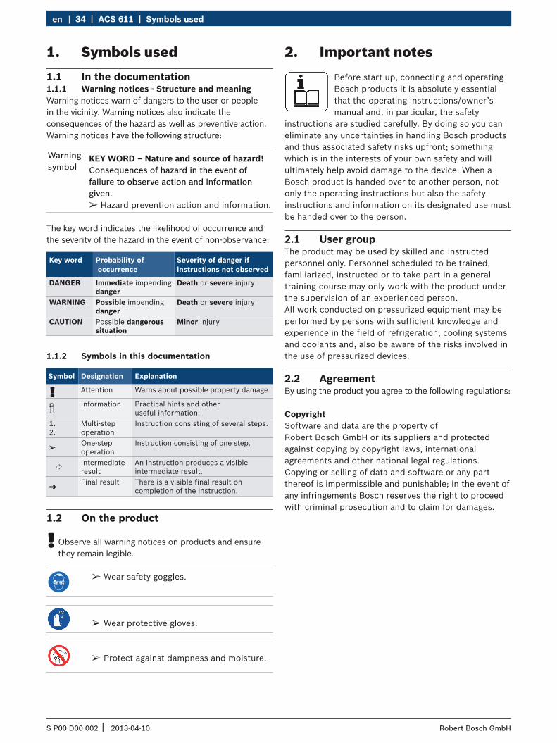
1. Symbols used1.1 In the documentation1.1.1 Warning notices - Structure and meaningWarning notices warn of dangers to the user or people in the vicinity. Warning notices also indicate the consequences of the hazard as well as preventive action. Warning notices have the following structure:
Warning symbol
KEY WORD – Nature and source of hazard!Consequences of hazard in the event of failure to observe action and information given.
¶ Hazard prevention action and information.
The key word indicates the likelihood of occurrence and the severity of the hazard in the event of non-observance:
Key word Probability of occurrence
Severity of danger if instructions not observed
DANGER Immediate impending danger
Death or severe injury
WARNING Possible impending danger
Death or severe injury
CAUTION Possible dangerous situation
Minor injury
1.1.2 Symbols in this documentation
Symbol Designation Explanation
! Attention Warns about possible property damage.
i Information Practical hints and other useful information.
1.2.
Multi-step operation
Instruction consisting of several steps.
e One-step operation
Instruction consisting of one step.
Intermediate result
An instruction produces a visible intermediate result.
" Final result There is a visible final result on completion of the instruction.
1.2 On the product
! Observe all warning notices on products and ensure they remain legible.
2. Important notes Before start up, connecting and operating
Bosch products it is absolutely essential that the operating instructions/owner’s manual and, in particular, the safety
instructions are studied carefully. By doing so you can eliminate any uncertainties in handling Bosch products and thus associated safety risks upfront; something which is in the interests of your own safety and will ultimately help avoid damage to the device. When a Bosch product is handed over to another person, not only the operating instructions but also the safety instructions and information on its designated use must be handed over to the person.
2.1 User groupThe product may be used by skilled and instructed personnel only. Personnel scheduled to be trained, familiarized, instructed or to take part in a general training course may only work with the product under the supervision of an experienced person.All work conducted on pressurized equipment may be performed by persons with sufficient knowledge and experience in the field of refrigeration, cooling systems and coolants and, also be aware of the risks involved in the use of pressurized devices.
2.2 AgreementBy using the product you agree to the following regulations:
CopyrightSoftware and data are the property of Robert Bosch GmbH or its suppliers and protected against copying by copyright laws, international agreements and other national legal regulations. Copying or selling of data and software or any part thereof is impermissible and punishable; in the event of any infringements Bosch reserves the right to proceed with criminal prosecution and to claim for damages.
¶ Wear safety goggles.
¶ Wear protective gloves.
¶ Protect against dampness and moisture.

S P00 D00 002 2013-04-10| Robert Bosch GmbH
Symbols used | ACS 611 | 35 en
2.3 Obligation of contractorThe contractor is obliged to ensure that all measures geared towards the prevention of accidents, industrial diseases, labor-related health risks are taken and measures towards making the workplace fit for people to work in are carried out.
Specifications for electrical systems (BGV A3)Electrical engineering in Germany is subject to the accident prevention regulations of the trade association "Electrical Plant and Equipment as under BGV A3 (previously VBG 4)". In all other countries, the applicable national regulations acts or decrees are to be adhered to.
LiabilityAll data in this program is based - where possible - on manufacturer and importer details. Bosch does not accept liability for the correctness and completeness of software and data; liability for damage caused by faulty software and data is ruled out. Whatever the event, Bosch liability is restricted to the amount for which the customer actually pays for this product. This disclaimer of liability does not apply to damages caused by intent or gross negligence on the part of Bosch.
WarrantyAny use of non-approved hardware and software will result in a modification to our product and thus to exclusion of any liability and warranty, even if the hardware or software has in the meantime been removed or deleted.
No changes may be made to our products. Our products may only be used in combination with original accessories and original service parts. Failing to do so, will render null and void all warranty claims.
This product may only be operated using Bosch approved operating systems. If the product is operated using an operating system other than the approved one, then our warranty obligation pursuant to our supply conditions will be rendered null and void. Furthermore, we will not be held liable for damage and consequential damage incurred through the use of a non-approved operating system.
Basic rulesThe contractor is bound to ensure that all electrical equipment and operating material is set up, modified and maintained by skilled electricians only or under the guidance and supervision of a skilled electrician in accordance with electrical engineering principles.
Furthermore, the contractor must ensure that all electrical equipment and operating material is operated in keeping with electrical engineering principles.
If a piece of electrical equipment or operating material is found to be defective, i.e. it does not or no longer complies with electrical engineering principles, the contractor must ensure that the fault is rectified immediately and, in the event that imminent danger exists, also ensure that the electrical equipment or the electrical operating material is not used.
Tests (taking Germany as an example): R The contractor must ensure that all electrical
systems and equipment are tested by a qualified electrician or under the guidance of a qualified electrician to ensure they are in proper working order: $ Before starting for the first time. $ After modification or repair before starting for the
first time. $ At given intervals. Set intervals such as to ensure
that faults that can be expected to occur are determined in good time.
R The test is to take the electrical engineering principles relating hereto into account.
R Upon request of the trade association, a test manual is to be maintained into which specific entries are made.

S P00 D00 002 2013-04-10| Robert Bosch GmbH
36 | ACS 611 | Symbols useden
2.4 Safety regulationsAlways carefully read and observe all the safety regulations before using the Bosch product.
Avoid all skin contact with the refrigerant. The low boiling point of the refrigerant (approx. -30 °C) can lead to frostbites. Should it nevertheless come into contact with the skin, remove any moistened clothing immediately and rinse the affected skin with copious amounts of water.
R Avoid all skin contact with the UV dye. Should it nevertheless come into contact with the skin, remove any moistened clothing immediately and rinse the affected skin with copious amounts of water.
R R134a is colorless, has a weak intrinsic odor and is heavier than air. It displaces oxygen and may flow into repair pits. Should refrigerant escape (malfunction), always ensure adequate ventilation and air extraction (especially in pits). Exit the workshop.
Never inhale refrigerant, dye and oil vapors. The vapors can irritate the eyes, nose and respiratory system. If liquid refrigerant or UV dye comes into contact with the eyes, rinse them thoroughly with water for 15 minutes. Then obtain medical help even if no pain is felt.
R Never swallow UV dye. If swallowed inadvertently, never attempt to induce vomiting. Drink copious amounts of water and obtain medical help.
R Before connecting the ACS 611 to a vehicle air conditioner or an external refrigerant cylinder, make sure the quick-release couplings are not leaking. Only ever use external refrigerant cylinders provided with safety valves and certified in line with the applicable standards.
R Before switching off the ACS 611, make sure all filling and drainage operations have been completed. This prevents refrigerant escaping into the environment.
Never use compressed air with R134a. Certain mixtures of air and R134a are highly flammable. Such mixtures are a potential hazard and may lead to fire or explosions and thus cause damage or injury.
R Refrigerant extracted from a vehicle air conditioner may be contaminated with moisture, lubricant, dirt and traces of other gases.
R R134a is not to be used in areas in which there is a danger of explosion. Fire, naked flames and smoking are prohibited. Welding and soldering are not permitted.
R High temperatures and UV radiation may chemically separate the R134a. The resultant products cause coughing and nausea.
R R134a is not to be mixed with other refrigerants. The mixing of refrigerants could damage the vehicle air conditioner.
If high-voltage components or high-voltage wires are inappropriately handled, there is a risk of fatal injury from high voltages and the possible transmission of current through the body.
R De-energization is only to be performed by a qualified electrician, a qualified electrician for specific tasks (hybrid), or a power systems engineer.
R Work on vehicles with high-voltage components is only ever to be performed in a safe, de-energized condition by persons with the minimum qualification "Trained to perform electrical work".
R Even after deactivating the high-voltage vehicle electrical system, the high-voltage battery may still be live.
R The operating condition cannot be established from any running noise, as the electric machine is silent when stationary.
R In gear positions "P" and "N" the engine or electric motor may start spontaneously depending on the charge of the high-voltage battery.
R Never open or damage high-voltage batteries. R On accident vehicles, never touch high-voltage
components or exposed high-voltage wires before deactivating the high-voltage vehicle electrical system.
S P00 D00 002 2013-04-10| Robert Bosch GmbH
Symbols used | ACS 611 | 37 en
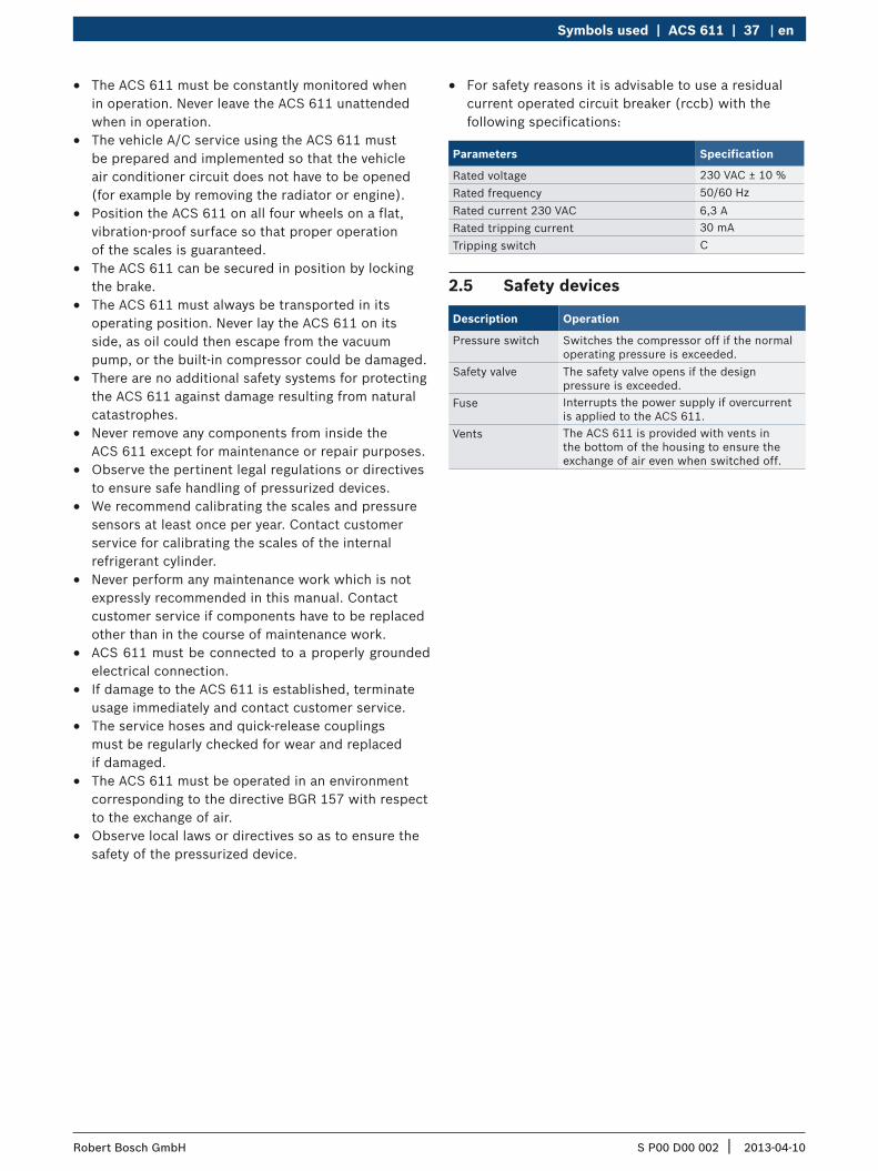
R The ACS 611 must be constantly monitored when in operation. Never leave the ACS 611 unattended when in operation.
R The vehicle A/C service using the ACS 611 must be prepared and implemented so that the vehicle air conditioner circuit does not have to be opened (for example by removing the radiator or engine).
R Position the ACS 611 on all four wheels on a flat, vibration-proof surface so that proper operation of the scales is guaranteed.
R The ACS 611 can be secured in position by locking the brake.
R The ACS 611 must always be transported in its operating position. Never lay the ACS 611 on its side, as oil could then escape from the vacuum pump, or the built-in compressor could be damaged.
R There are no additional safety systems for protecting the ACS 611 against damage resulting from natural catastrophes.
R Never remove any components from inside the ACS 611 except for maintenance or repair purposes.
R Observe the pertinent legal regulations or directives to ensure safe handling of pressurized devices.
R We recommend calibrating the scales and pressure sensors at least once per year. Contact customer service for calibrating the scales of the internal refrigerant cylinder.
R Never perform any maintenance work which is not expressly recommended in this manual. Contact customer service if components have to be replaced other than in the course of maintenance work.
R ACS 611 must be connected to a properly grounded electrical connection.
R If damage to the ACS 611 is established, terminate usage immediately and contact customer service.
R The service hoses and quick-release couplings must be regularly checked for wear and replaced if damaged.
R The ACS 611 must be operated in an environment corresponding to the directive BGR 157 with respect to the exchange of air.
R Observe local laws or directives so as to ensure the safety of the pressurized device.
R For safety reasons it is advisable to use a residual current operated circuit breaker (rccb) with the following specifications:
Parameters Specification
Rated voltage 230 VAC ± 10 % Rated frequency 50/60 HzRated current 230 VAC 6,3 A Rated tripping current 30 mATripping switch C
2.5 Safety devices
Description Operation
Pressure switch Switches the compressor off if the normal operating pressure is exceeded.
Safety valve The safety valve opens if the design pressure is exceeded.
Fuse Interrupts the power supply if overcurrent is applied to the ACS 611.
Vents The ACS 611 is provided with vents in the bottom of the housing to ensure the exchange of air even when switched off.
S P00 D00 002 2013-04-10| Robert Bosch GmbH
38 | ACS 611 | Product descriptionen
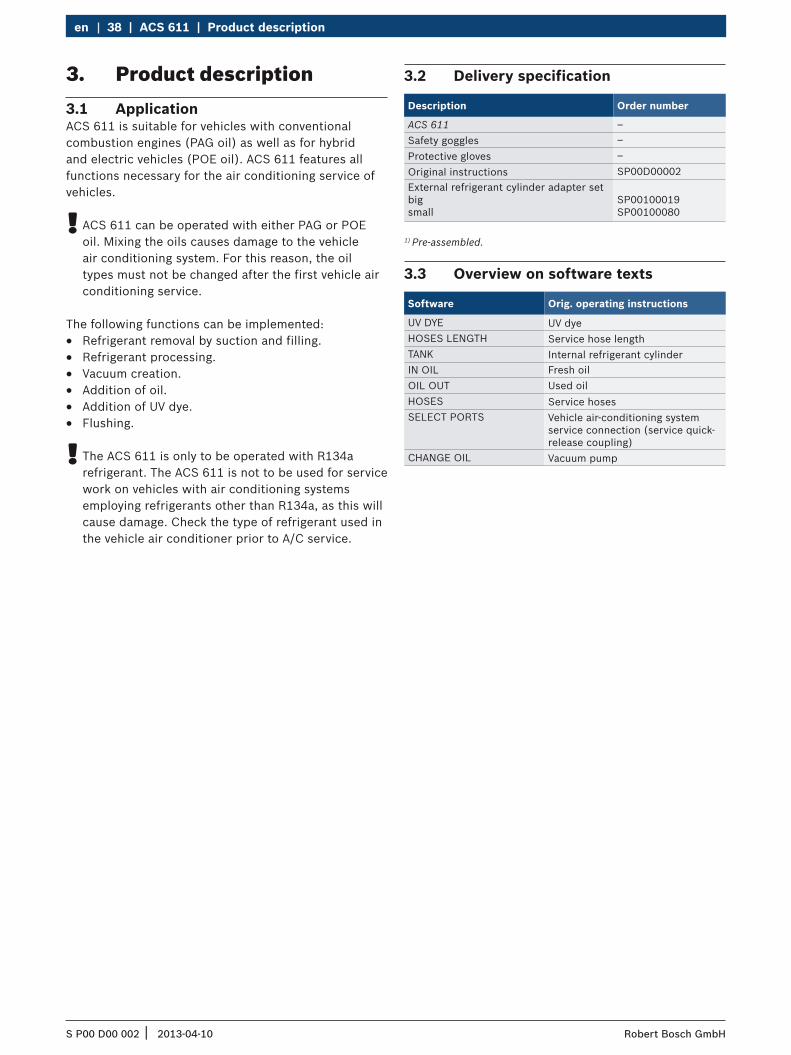
3. Product description3.1 ApplicationACS 611 is suitable for vehicles with conventional combustion engines (PAG oil) as well as for hybrid and electric vehicles (POE oil). ACS 611 features all functions necessary for the air conditioning service of vehicles.
! ACS 611 can be operated with either PAG or POE oil. Mixing the oils causes damage to the vehicle air conditioning system. For this reason, the oil types must not be changed after the first vehicle air conditioning service.
The following functions can be implemented: R Refrigerant removal by suction and filling. R Refrigerant processing. R Vacuum creation. R Addition of oil. R Addition of UV dye. R Flushing.
! The ACS 611 is only to be operated with R134a refrigerant. The ACS 611 is not to be used for service work on vehicles with air conditioning systems employing refrigerants other than R134a, as this will cause damage. Check the type of refrigerant used in the vehicle air conditioner prior to A/C service.
3.2 Delivery specification
Description Order number
ACS 611 –Safety goggles –Protective gloves –Original instructions SP00D00002External refrigerant cylinder adapter set big small
SP00100019 SP00100080
1) Pre-assembled.
3.3 Overview on software texts
Software Orig. operating instructions
UV DYE UV dyeHOSES LENGTH Service hose lengthTANK Internal refrigerant cylinderIN OIL Fresh oilOIL OUT Used oilHOSES Service hosesSELECT PORTS Vehicle air-conditioning system
service connection (service quick-release coupling)
CHANGE OIL Vacuum pump
S P00 D00 002 2013-04-10| Robert Bosch GmbH
Product description | ACS 611 | 39 en
1
5
4
3
2
6
7
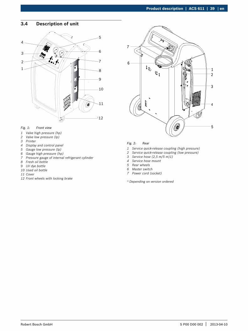
Fig. 2: Rear1 Service quick-release coupling (high pressure)2 Service quick-release coupling (low pressure)3 Service hose (2,5 m/5 m)1)4 Service hose mount5 Rear wheels6 Master switch7 Power cord (socket)
1) Depending on version ordered
3.4 Description of unit
4
6
5
1
2
3
8
7
9
10
12
11
Fig. 1: Front view1 Valve high pressure (hp)2 Valve low pressure (lp)3 Printer4 Display and control panel5 Gauge low pressure (lp)6 Gauge high pressure (hp)7 Pressure gauge of internal refrigerant cylinder8 Fresh oil bottle9 UV dye bottle10 Used oil bottle 11 Cover12 Front wheels with locking brake
S P00 D00 002 2013-04-10| Robert Bosch GmbH
40 | ACS 611 | Product descriptionen
7
8
910
1
4
3
2
5
6
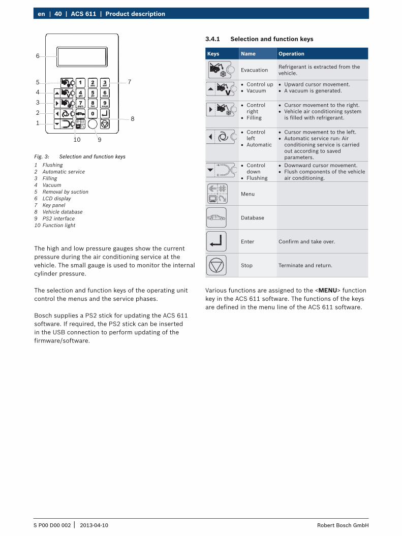
Fig. 3: Selection and function keys1 Flushing2 Automatic service3 Filling4 Vacuum5 Removal by suction6 LCD display7 Key panel8 Vehicle database9 PS2 interface10 Function light
The high and low pressure gauges show the current pressure during the air conditioning service at the vehicle. The small gauge is used to monitor the internal cylinder pressure.
The selection and function keys of the operating unit control the menus and the service phases.
Bosch supplies a PS2 stick for updating the ACS 611 software. If required, the PS2 stick can be inserted in the USB connection to perform updating of the firmware/software.
3.4.1 Selection and function keys
Keys Name Operation
Evacuation Refrigerant is extracted from the vehicle.
R Control up R Vacuum
R Upward cursor movement. R A vacuum is generated.
R Control right
R Filling
R Cursor movement to the right. R Vehicle air conditioning system
is filled with refrigerant.
R Control left
R Automatic
R Cursor movement to the left. R Automatic service run: Air
conditioning service is carried out according to saved parameters.
R Control down
R Flushing
R Downward cursor movement. R Flush components of the vehicle
air conditioning.
Menu
Database
Enter Confirm and take over.
Stop Terminate and return.
Various functions are assigned to the <MENU> function key in the ACS 611 software. The functions of the keys are defined in the menu line of the ACS 611 software.
S P00 D00 002 2013-04-10| Robert Bosch GmbH
Product description | ACS 611 | 41 en
3.4.2 Input keysThe input keys can be used to enter letters, numbers and special characters in the input boxes.
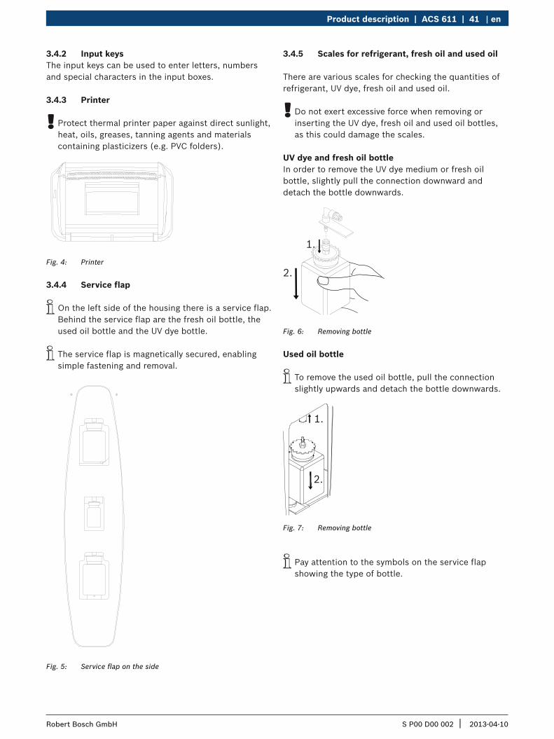
3.4.3 Printer
! Protect thermal printer paper against direct sunlight, heat, oils, greases, tanning agents and materials containing plasticizers (e.g. PVC folders).
Fig. 4: Printer
3.4.4 Service flap
i On the left side of the housing there is a service flap. Behind the service flap are the fresh oil bottle, the used oil bottle and the UV dye bottle.
i The service flap is magnetically secured, enabling simple fastening and removal.
Fig. 5: Service flap on the side
3.4.5 Scales for refrigerant, fresh oil and used oil
There are various scales for checking the quantities of refrigerant, UV dye, fresh oil and used oil.
! Do not exert excessive force when removing or inserting the UV dye, fresh oil and used oil bottles, as this could damage the scales.
UV dye and fresh oil bottleIn order to remove the UV dye medium or fresh oil bottle, slightly pull the connection downward and detach the bottle downwards.
1.
2.
Fig. 6: Removing bottle
Used oil bottle
i To remove the used oil bottle, pull the connection slightly upwards and detach the bottle downwards.
1.
2.
Fig. 7: Removing bottle
i Pay attention to the symbols on the service flap showing the type of bottle.
S P00 D00 002 2013-04-10| Robert Bosch GmbH
42 | ACS 611 | Product descriptionen
3.4.6 Service hose and service quick-release coupling
i When not in use, the service hoses can be wound up on the side of the ACS 611 and fixated with the service quick-release couplings.
i Turn the knurled part of the service quick-release coupling clockwise to open the valve. A counterclockwise turn closes the valve.
i To remove the service quick-release couplings from the holders, press the coupling slightly towards the connection and carefully pull the knurled section back to unfasten it from the holder.
3.4.7 Locking brakesRolling of the ACS 611 can be prevented by locking the brakes at the front wheels.
3.4.8 Power cord
! Have the country-specific power cord connected by a qualified electrician.
i The power cord is firmly connected to ACS 611.
3.4.9 Master switchTurn the main switch clockwise to turn on the ACS 611.
3.5 Description of functionThe refrigerant recovered from the air conditioner passes through the combo filter to remove suspended particles and moisture.
The purpose of the vacuum pump is to generate a vacuum in the air conditioner and to detect possible leaks in the vehicle air conditioner.
Used oil separated from the recovered vehicle refrigerant flows into the used oil bottle.
Oil from the fresh oil bottle is used to refill the air conditioner compressor oil.
The vehicle air conditioner is partly filled with UV dye to facilitate the detection of leaks in the event of damage to the vehicle air conditioner.
The refrigerant in the internal refrigerant cylinder is used for filling the vehicle air conditioner.
The venting unit for non-condensable gases always takes effect when the vessel pressure is higher than the saturation pressure.
S P00 D00 002 2013-04-10| Robert Bosch GmbH
Program structure | ACS 611 | 43 en
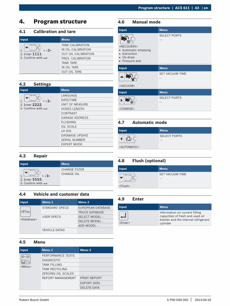
4. Program structure4.1 Calibration and tare
Input Menu
1. + <3>2. Enter 1111.3. Confirm with E.
TANK CALIBRATIONIN OIL CALIBRATIONOUT OIL CALIBRATIONPRES. CALIBRATIONTANK TAREIN OIL TAREOUT OIL TARE
4.2 SettingsInput Menu
1. + <3> 2. Enter 2222.3. Confirm with E.
LANGUAGEDATE/TIMEUNIT OF MEASUREHOSES LENGTHCONTRASTGARAGE ADDRESSFLUSHINGOIL SCALEUV DYEDATABASE UPDATESERIAL NUMBEREXPERT MODE
4.3 Repair
Input Menu
1. + <3> 2. Enter 5555.3. Confirm with E.
CHANGE FILTERCHANGE OIL
4.4 Vehicle and customer data
Input Menu 1 Menu 2
<Database>
STANDARD SPECS EUROPEAN DATABASETRUCK DATABASE
USER SPECS SELECT MODEL :DELETE MODEL :ADD MODEL :
VEHICLE DATAS
4.5 Menu
Input Menu 1 Menu 2
<Menu>
PERFORMANCE TESTSDIAGNOSTICTANK FILLINGTANK RECYCLINGZEROING OIL SCALESREPORT MANAGEMENT PRINT REPORT
EXPORT DATADELETE DATA
4.6 Manual mode
Input Menu
<RECOVERY> R Automatic emptying R Extraction R Oil drain R Pressure test
SELECT PORTS...
Input Menu
<VACUUM>
SET VACUUM TIME...
Input Menu
<CHARGE>
SELECT PORTS...
4.7 Automatic mode
Input Menu
<AUTOMATIC>
SELECT PORTS...
4.8 Flush (optional)
Input Menu
<Flush>
SET VACUUM TIME...
4.9 Enter
Input Menu
<Enter>
Information on current filling capacities of fresh and used oil bottles and the internal refrigerant cylinder
S P00 D00 002 2013-04-10| Robert Bosch GmbH
44 | ACS 611 | Initial commissioningen
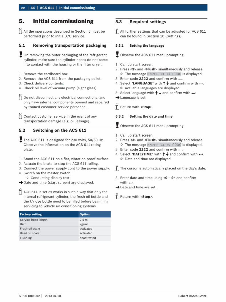
5. Initial commissioning i All the operations described in Section 5 must be performed prior to initial A/C service.
5.1 Removing transportation packaging
! On removing the outer packaging of the refrigerant cylinder, make sure the cylinder hoses do not come into contact with the housing or the filter dryer.
1. Remove the cardboard box.2. Remove the ACS 611 from the packaging pallet.3. Check delivery contents.4. Check oil level of vacuum pump (sight glass).
i Do not disconnect any electrical connections, and only have internal components opened and repaired by trained customer service personnel.
i Contact customer service in the event of any transportation damage (e.g. oil leakage).
5.2 Switching on the ACS 611
! The ACS 611 is designed for 230 volts, 50/60 Hz. Observe the information on the ACS 611 rating plate.
1. Stand the ACS 611 on a flat, vibration-proof surface.2. Actuate the brake to stop the ACS 611 rolling.3. Connect the power supply cord to the power supply.4. Switch on the master switch.
Conducting display test. "Date and time (start screen) are displayed.
i ACS 611 is set ex-works in such a way that only the internal refrigerant cylinder, the fresh oil bottle and the UV dye bottle need to be filled before beginning servicing to vehicle air conditioning systems.
Factory setting Option
Service hose length 2.5 mUnit kg/mlFresh oil scale activatedUsed oil scale activatedFlushing deactivated
5.3 Required settings
i All further settings that can be adjusted for ACS 611 can be found in Section 10 (Settings).
5.3.1 Setting the language
! Observe the ACS 611 menu prompting.
1. Call up start screen.2. Press <3> and <Flush> simultaneously and release.
The message ENTER CODE 0000 is displayed.3. Enter code 2222 and confirm with E.4. Select "LANGUAGE" with o u and confirm with E.
Available languages are displayed.5. Select language with o u and confirm with E.
"Language is set.
i Return with <Stop>.
5.3.2 Setting the date and time
! Observe the ACS 611 menu prompting.
1. Call up start screen.2. Press <3> and <Flush> simultaneously and release.
The message ENTER CODE 0000 is displayed.3. Enter code 2222 and confirm with E.4. Select "DATE/TIME" with o u and confirm with E.
Date and time are displayed.
i The cursor is automatically placed on the day's date.
5. Enter date and time using <0 – 9> and confirm with E. "Date and time are set.
i Return with <Stop>.
S P00 D00 002 2013-04-10| Robert Bosch GmbH
Initial commissioning | ACS 611 | 45 en
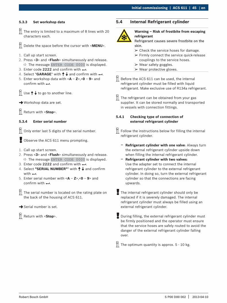
5.3.3 Set workshop data
i The entry is limited to a maximum of 8 lines with 20 characters each.
i Delete the space before the cursor with <MENU>.
1. Call up start screen.2. Press <3> and <Flush> simultaneously and release.
The message ENTER CODE 0000 is displayed.3. Enter code 2222 and confirm with E. 4. Select "GARAGE" with o u and confirm with E. 5. Enter workshop data with <A – Z>,<0 – 9> and
confirm with E.
i Use o u to go to another line.
"Workshop data are set.
i Return with <Stop>.
5.3.4 Enter serial number
i Only enter last 5 digits of the serial number.
! Observe the ACS 611 menu prompting.
1. Call up start screen.2. Press <3> and <Flush> simultaneously and release.
The message ENTER CODE 0000 is displayed.3. Enter code 2222 and confirm with E. 4. Select "SERIAL NUMBER"" with o u and confirm
with E. 5. Enter serial number with <A – Z>,<0 – 9> and
confirm with E.
i The serial number is located on the rating plate on the back of the housing of ACS 611.
"Serial number is set.
i Return with <Stop>.
5.4 Internal Refrigerant cylinder
Warning – Risk of frostbite from escaping refrigerantRefrigerant causes severe frostbite on the skin.
¶ Check the service hoses for damage. ¶ Firmly connect the service quick-release couplings to the service hoses.
¶ Wear safety goggles. ¶ Wear protective gloves.
i Before the ACS 611 can be used, the internal refrigerant cylinder must be filled with liquid refrigerant. Make exclusive use of R134a refrigerant.
i The refrigerant can be obtained from your gas supplier. It can be stored normally and transported in vessels with connection fittings.
5.4.1 Checking type of connection of external refrigerant cylinder
i Follow the instructions below for filling the internal refrigerant cylinder.
$ Refrigerant cylinder with one valve: Always turn the external refrigerant cylinder upside down when filling the internal refrigerant cylinder.
$ Refrigerant cylinder with two valves: Use the adapter set to connect the internal refrigerant cylinder to the external refrigerant cylinder. In doing so, turn the external refrigerant cylinder so that the connections are facing upwards.
! The internal refrigerant cylinder should only be replaced if it is severely damaged. The internal refrigerant cylinder must always be filled using an external refrigerant cylinder.
! During filling, the external refrigerant cylinder must be firmly positioned and the operator must ensure that the service hoses are safely routed to avoid the danger of the external refrigerant cylinder falling over.
i The optimum quantity is approx. 5 - 10 kg.
S P00 D00 002 2013-04-10| Robert Bosch GmbH
46 | ACS 611 | Initial commissioningen
! Do not interrupt the automatic filling process prior to automatic termination by the ACS 611.
! ACS 611 automatically empties the service hoses and internal lines after charge of the internal refrigerant cylinder using suction. This additional quantity causes the actual filling capacity to deviate + 500 g – 700 g from the filled in refrigerant quantity.
5.4.2 Filling internal refrigerant cylinder
<MENU> key
! Observe the ACS 611 menu prompting.
1. Press <MENU>.2. Select "TANK FILLING" with o u and confirm with
E. Max. quantity to be charged is displayed.
3. Enter filling capacity with <0 – 9> and confirm with E.
Filling process starts.
i The current pressure inside the external refrigerant cylinder is indicated on the high/low-pressure gauge.
i ACS 611 ends the filling process when the entered refrigerant quantity is reached.
" Internal refrigerant cylinder is full.
i Call up start screen to check refrigerant quantity in internal refrigerant cylinder and press E.
i Return with <Stop>.
6. A/C service preparationWarning – Risk of burns from hot engine componentsContact with hot engine components will cause severe burns.
¶ Allow the engine to cool down. ¶ Wear protective gloves.
Warning – Risk of frostbite from escaping refrigerantRefrigerant causes severe frostbite on the skin.
¶ Check the service hoses for damage. ¶ Firmly connect the service quick-release couplings to the service hoses.
¶ Wear safety goggles. ¶ Wear protective gloves.
i Observe the vehicle manufacturer's recommendations for A/C service on vehicles with a low-pressure connection only.
1. Stand the ACS 611 on a flat, vibration-proof surface.2. Actuate the brake to stop the ACS 611 rolling.3. Connect the power supply cord to the power supply.4. Switch on the master switch.
! Observe the manufacturer's instructions for the corresponding vehicle before performing A/C service.
! The ACS 611 is only to be operated with R134a refrigerant. Check which refrigerant is used for the vehicle before performing A/C service.
! The ACS 611 cannot be used for air conditioners repaired using a chemical sealant. Non-observance will invalidate the warranty.
! Never attempt to close the valves of the internal refrigerant cylinder whilst the ACS 611 is in operation.
S P00 D00 002 2013-04-10| Robert Bosch GmbH
Operating instructions | ACS 611 | 47 en
7. Operating instructions7.1 Database
<DATA BASE> key
7.1.1 Vehicle database
i The filling data can be taken directly from the internal database and printed.
! Observe the ACS 611 menu prompting.
1. Call up start screen.2. Press <DATA BASE>.3. Select "STANDARD SPECS" with o u and confirm
with E.4. Select "EUROPEAN DATABASE" or
"TRUCK DATABASE" with o u and confirm with E.5. Select vehicle (manufacturer) with o u and confirm
with E.6. Select type (model) with o u and confirm with E.
"Vehicle is selected.7. <1>, <2> Take over data or display.
i Return with <Stop>.
7.1.2 Personal database
i A personal database with the data of the new vehicles which are not included in the standard database can be created.
! Observe the ACS 611 menu prompting.
1. Press <DATABASE>.2. Select USER SPECS with o u and confirm with E.3. Enter data with <A – Z>, <0 – 9> and confirm
with E.
i <MENU> deletes character to left of cursor. Navigate the cursor to the next line with E. Navigate inside the window with o u, z or v.
i There are 4 lines with 20 characters for the vehicle description, and 1 line with each 20 characters for the refrigerant quantity, oil quantity and oil type available.
7.1.3 Customer and vehicle data
! Observe the ACS 611 menu prompting.
1. Call up start screen.2. Press <DATA BASE>.3. Select "VEHICLE DATAS" with o u and confirm with
E.4. Enter data with <A – Z>, <0 – 9> and confirm
with E.
i <MENU> deletes character to left of cursor.
i Return with <Stop>.
7.2 Service phases
R Recovery phase: Refrigerant extracted from the vehicle, cleaned and routed into the internal refrigerant cylinder.
R Vacuum phase: A vacuum is generated in the vehicle air conditioner and the system is checked for leaks.
R Filling phase: $ Fresh oil: Fresh oil is added to the vehicle air
conditioner. $ UV dye: UV dye is added to the vehicle air
conditioner. $ Refrigerant: A certain quantity of R134a
refrigerant is added to the vehicle air conditioner.

S P00 D00 002 2013-04-10| Robert Bosch GmbH
48 | ACS 611 | Operating instructionsen
7.3 Manual service
i The service parameters (vacuum generation time, recharge quantity and oil type) can be found in the owner's manual or the vehicle repair manual.
i With the ACS 611 all service phases can be performed manually.
i Individual service phases are linked as standard to other service phases as they are needed to fully implement the individual operation selected.
i R134a can only be added to an air conditioner under vacuum. The vacuum phase must therefore be implemented before filling with R134a.
i Observe the vehicle-specific information before altering the quantity of oil.
7.3.1 Filling of refrigerant, fresh oil and UV dye
i Fresh oil and UV dye can only be added to an air conditioning system under vacuum. A vacuum must be generated prior to the oil/UV dye filling process.
i If pressure is detected in the vehicle air conditioning system during filling, recovery must be implemented in order to continue.
i Fresh oil and UV dye can only be added in conjunction with R134a.
! Always observe the vehicle manufacturer's instructions before altering the oil quantity.
! Before filling with UV dye it is essential to check whether leak testing of the air conditioning system with UV dye is approved by the vehicle manufacturer.
! Filling should, if possible, only occur via the high pressure connection. For systems that have only one low-pressure connection, at least 10 minutes must pass after filling before the vehicle air conditioning system can be switched on.
<Fill> key
! Observe the ACS 611 menu prompting.
1. Call up start screen.2. Press <Fill>.
SELECT PORTS? 1 HP & LP PORTS 2 HP PORT 3 LP PORT
3. Select <1>,<2> or <3>; confirm with E. CHARGING UV DYE? 1 - YES 2 - NO
4. Select <1> or <2>; confirm with E. CHARGING OIL? 1 - YES 2 - NO
i With <1> the fresh oil quantity must be set with <0 – 9>, z v and confirmed with E.
5. Select <1> or <2>; confirm with E. SET REFRIGERANT CHARGE is displayed.
6. Enter refrigerant quantity (R134a) with <0 – 9>, z v and confirm with E. "ACS 611 performs recharge phase.
i Return with <Stop>.
S P00 D00 002 2013-04-10| Robert Bosch GmbH
Operating instructions | ACS 611 | 49 en
7.3.2 Recovery
i During the recovery phase ACS 611 automatically empties the service hoses and separates the extracted oil from the refrigerant which flows into the oil bottle.
i The pressure in the vehicle air conditioner must be checked prior to and during the recovery phase.
! Observe ACS 611 menu prompting.
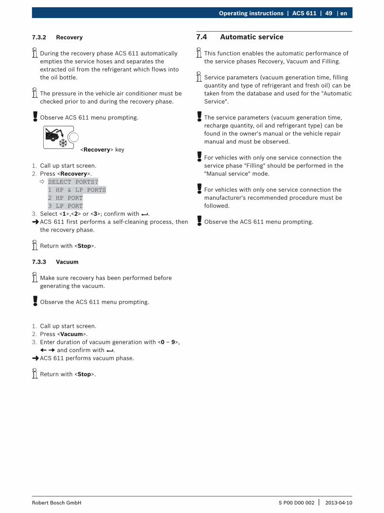
<Recovery> key
1. Call up start screen.2. Press <Recovery>.
SELECT PORTS? 1 HP & LP PORTS 2 HP PORT 3 LP PORT
3. Select <1>,<2> or <3>; confirm with E. "ACS 611 first performs a self-cleaning process, then the recovery phase.
i Return with <Stop>.
7.3.3 Vacuum
i Make sure recovery has been performed before generating the vacuum.
! Observe the ACS 611 menu prompting.
1. Call up start screen.2. Press <Vacuum>.3. Enter duration of vacuum generation with <0 – 9>,
z v and confirm with E. "ACS 611 performs vacuum phase.
i Return with <Stop>.
7.4 Automatic service
i This function enables the automatic performance of the service phases Recovery, Vacuum and Filling.
i Service parameters (vacuum generation time, filling quantity and type of refrigerant and fresh oil) can be taken from the database and used for the "Automatic Service".
! The service parameters (vacuum generation time, recharge quantity, oil and refrigerant type) can be found in the owner's manual or the vehicle repair manual and must be observed.
! For vehicles with only one service connection the service phase "Filling" should be performed in the "Manual service" mode.
! For vehicles with only one service connection the manufacturer's recommended procedure must be followed.
! Observe the ACS 611 menu prompting.
S P00 D00 002 2013-04-10| Robert Bosch GmbH
50 | ACS 611 | Operating instructionsen
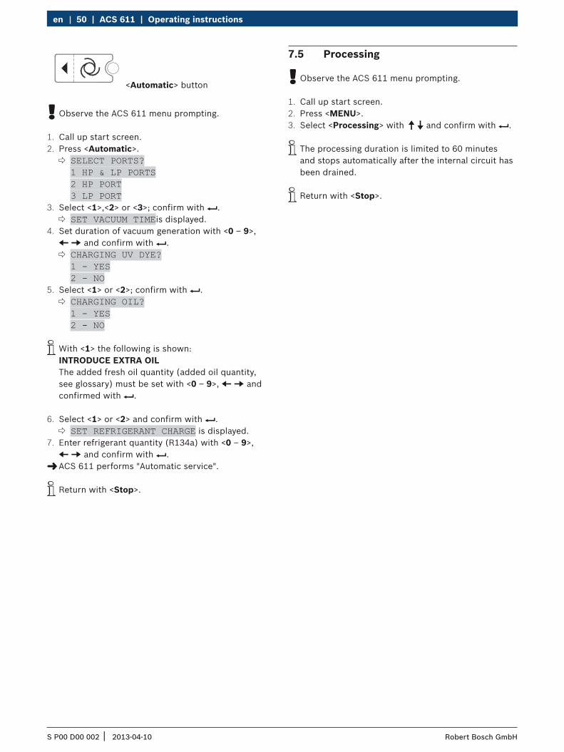
<Automatic> button
! Observe the ACS 611 menu prompting.
1. Call up start screen.2. Press <Automatic>.
SELECT PORTS? 1 HP & LP PORTS 2 HP PORT 3 LP PORT
3. Select <1>,<2> or <3>; confirm with E. SET VACUUM TIMEis displayed.
4. Set duration of vacuum generation with <0 – 9>, z v and confirm with E.
CHARGING UV DYE? 1 - YES 2 - NO
5. Select <1> or <2>; confirm with E. CHARGING OIL? 1 - YES 2 - NO
i With <1> the following is shown: INTRODUCE EXTRA OIL The added fresh oil quantity (added oil quantity, see glossary) must be set with <0 – 9>, z v and confirmed with E.
6. Select <1> or <2> and confirm with E. SET REFRIGERANT CHARGE is displayed.
7. Enter refrigerant quantity (R134a) with <0 – 9>, z v and confirm with E. "ACS 611 performs "Automatic service".
i Return with <Stop>.
7.5 Processing
! Observe the ACS 611 menu prompting.
1. Call up start screen. 2. Press <MENU>.3. Select <Processing> with o u and confirm with E.
i The processing duration is limited to 60 minutes and stops automatically after the internal circuit has been drained.
i Return with <Stop>.

S P00 D00 002 2013-04-10| Robert Bosch GmbH
Troubleshooting | ACS 611 | 51 en
8. Troubleshooting i Please contact customer service if any of the actions suggested in this Section can not be implemented.
8.1 Service prompt
Messages Actions
CHANGE OIL Change vacuum pump oil.
REPLACE FILTER Combo filter replacement (see Section 7.3).
8.2 Fault messages
Messages Actions
HIGH PRESSURE There is excess pressure at the outlet of the compressor. Switch off the station and wait approx. 30 minutes. If error persists, contact customer service.
PROGRAM ERROR If error persists, contact customer service.
FULL TANK The internal refrigerant cylinder has been filled to maximum filling level. Carry out several refill procedures in order to reduce the internal refrigerant quantity.
ZEROING OIL SCALES Error in scales setting. Perform "Tare scales". If error persists, contact customer service.
HIGH RECOVERY TIME The recovery time exceeds the set maximum duration. Check vehicle air conditioner for leaks. If error persists, contact customer service.
A/C SYSTEM EMPTY There is no refrigerant in the vehicle air conditioning system.
OUTOIL BOTTLE FULL CALIBRATE SCALE The used oil bottle is full and must be emptied.
OIL IN BOTTLE EMPTY FILL BOTTLE The fresh oil bottle is empty and must be refilled.
A/C SYSTEM FULL There is refrigerant in the air conditioning system.
INCOMPLETE CHARGE The filling time exceeds the set maximum duration. The bottle pressure equals the pressure in the vehicle air conditioning system. Inform customer service.
CHARGING OIL TIME HIGH The fresh oil filling time exceeds the set safety threshold.There is no vacuum in the vehicle air-conditioning system. Create vacuum first.

S P00 D00 002 2013-04-10| Robert Bosch GmbH
52 | ACS 611 | Diagnosisen
9. Diagnosis9.1 Preparatory work
The diagnosis function works only if a vehicle is selected in the database.
If no vehicle is selected ACS 611 opens the database and prompts to select a vehicle in order to perform a diagnosis.
! Park the vehicle in a place where it is protected from wind and sunlight. Even slight air movement can falsify the values.
! Observe the ACS 611 menu prompting.
1. Connect the service hoses to the vehicle.2. Lower the hood without locking it.3. Start engine (vehicle).
i The engine should have operating temperature.
4. Increase speed of vehicle to 1500 – 2000 rpm and hold.
5. Switch on the vehicle air-conditioning system.6. Open the fan openings (middle of vehicle).7. Set vehicle air-conditioning system to maximum
cooling capacity.8. Set fan to maximum ventilation.9. Switch off air circulation.10. Open doors and windows.
! Check if the compressor switches on.
i Wait (3 – 5 minutes) until the vehicle air-conditioning system cools evenly.
! Measure the ambient temperature properly. Measurements must be taken at a distance of approx. 1 m from the vehicle.
! Measuring in close vicinity of the engine can lead to a false diagnosis.
11. High-pressure gauge: Read highest pressure value when compressor is switched on.
12. Low-pressure gauge: Read lowest pressure value when compressor is switched on.
13. Temperature: Read mean air temperature value (at fan openings in the middle).
! The ACS 611 diagnostic software was developed to provide support and instruction for defects in vehicle air-conditioning systems. The diagnosis and recommendations serve only as a reference and do not constitute recommended repair instructions.
9.2 Diagnosis
! Observe the ACS 611 menu prompting.
1. Call up start screen.2. Press <MENU>.3. Select "DIAGNOSTIC" with o u and confirm with E. 4. Enter measured ambient temperature and confirm
with E.5. Enter the read pressure value (HP) and confirm
with E.6. Enter the read pressure value (LP) and confirm
with E.7. Enter air temperature measured at the fan openings
and confirm with E. Option <1> and <2> are displayed:
8. <1> Select result, display the entered data and the status, and print with E.
9. Call up diagnosis; display list of possible error causes and troubleshooting procedure with <2> and print with E.
i Return with <Stop>.
S P00 D00 002 2013-04-10| Robert Bosch GmbH
ACS 611 settings | ACS 611 | 53 en
10. ACS 611 settings10.1 Set unit
! Observe the ACS 611 menu prompting.
1. Call up start screen.2. Press <3> and <Flush> simultaneously and release.
The message ENTER CODE 0000 is displayed.3. Enter code 2222 and confirm with E. 4. Select "UNIT OF MEASURE" with o u and confirm
with E. kg/lb are displayed.
5. Select unit with o u and confirm with E. "Unit is set.
i Return with <Stop>.
10.2 Set length of service hoses
! Observe the ACS 611 menu prompting.
1. Call up start screen.2. Press <3> and <Flush> simultaneously and release.
The message ENTER CODE 0000 is displayed.3. Enter code 2222 and confirm with E. 4. Select "HOSES LENGTH" with o u and confirm with
E. Available lengths (2.5 m, 5 m, 7.5 m and 10 m) are displayed.
5. Select hose length with o u and confirm with E. "Hose length is set.
i Return with <Stop>.
10.3 Contrast
1. Call up start screen.2. Press <3> and <Flush> simultaneously and release.
The message ENTER CODE 0000 is displayed.3. Enter code 2222 and confirm with E. 4. Select "CONTRAST" with o u and confirm with E.
A numeric index is displayed on the screen indicating the contrast level.
5. Adjust contrast with o u and confirm with E. "Contrast is set.
i Return with <Stop>.
10.4 Flush (optional)
i Optionally, special accessories for the cleaning of vehicle A/C components can be connected for ACS 611. If these special accessories are used, this function must be activated in the selection menu.
1. Call up start screen.2. Press <3> and <Flush> simultaneously and release.
The message ENTER CODE 0000 is displayed.3. Enter code 2222 and confirm with E. 4. Select "FLUSHING" with o u and confirm with E.5. Activate or deactivate with o u and confirm with E.
"Flushing function is activated or deactivated.
i Return with <Stop>.
10.5 Scales for fresh and used oil
i In the event of faults the "oil charge" and "oil drain" scales can be switched off to avoid blocking of the unit.
1. Call up start screen.2. Press <3> and <Flush> simultaneously and release.
The message ENTER CODE 0000 is displayed.3. Enter code 2222 and confirm with E. 4. Select "OIL SCALE" with o u and confirm with E.5. Activate or deactivate with o u and confirm with E.
"Oil scales are activated or deactivated.
i Return with <Stop>.
10.6 UV dye
1. Call up start screen.2. Press <3> and <Flush> simultaneously and release.
The message ENTER CODE 0000 is displayed.3. Enter code 2222 and confirm with E. 4. Select "UV DYE" with o u and confirm with E.5. Activate or deactivate with o u and confirm with E.
"UV dye filling is activated or deactivated.
i Return with <Stop>.
! In order to avoid problems due to chemical incompatibility with the internal components of the service device, dyes approved by Bosch are to be used only.
S P00 D00 002 2013-04-10| Robert Bosch GmbH
54 | ACS 611 | Maintenanceen
10.7 Service data report
10.7.1 Activate/deactivate consumption R134a report
i ACS 611 can store the R134a consumption data during all filling and evacuation processes.
! Can be deactivated by customer service only.
10.7.2 Report printout
! The data storage of ACS 611 may contain more data than can be printed on one paper roll (printer).
! Observe the ACS 611 menu prompting.
1. Press <MENU>.2. Select "REPORT MANAGEMENT"" with o u and
confirm with E.3. Select "PRINT REPORT"" with o u and confirm with
E. The stored reports are displayed.
4. Select report with o u and confirm with E. "Report is printed.
i Return with <Stop>.
i It is recommended to print or delete the stored reports at least once a week.
11. Maintenance11.1 Spare and wearing parts
Description Order numberCombo filter SP00100001
Vacuum pump oil SP00100086Roll of paper for printer SP00100087Service hose (HP) 2,5 m SP00100029Service hose (HP) 5 m SP00100035Service hose (LP) 2,5 m SP00100030Service hose (LP) 5 m SP00100036Quick-release coupling (HP) SP00100083Quick-release coupling (LP) SP00100082Used oil bottle SP00100060Fresh oil bottle SP00100059UV dye bottle SP00100061Adapter set 2,5 m - 5 m SP00100075
11.2 Maintenance interval
Description Period
Calibration of fresh and used oil scales
Once a year or on change of fresh oil type
Vacuum pump oil replacement and system leak test
see display (10 h)
Replacement of combo filter see display (150 kg)
! Never perform any maintenance work which is not expressly recommended in this Section.
! Contact customer service if components have to be replaced other than in the course of maintenance work.
S P00 D00 002 2013-04-10| Robert Bosch GmbH
Maintenance | ACS 611 | 55 en
11.3 Tare oil scales
i The fresh oil and used oil scales should be reset to zero regularly (once a month) in order to ensure their accuracy and to avoid tolerances.
! Observe the ACS 611 menu prompting.
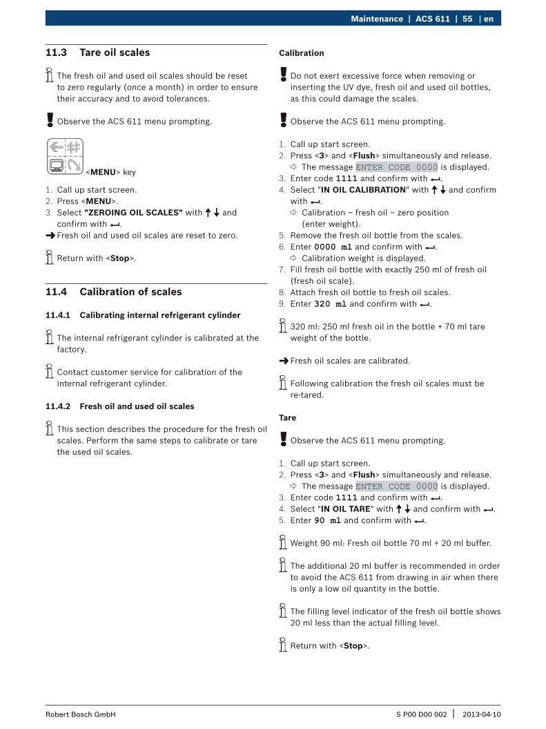
<MENU> key
1. Call up start screen.2. Press <MENU>.3. Select "ZEROING OIL SCALES" with o u and
confirm with E. "Fresh oil and used oil scales are reset to zero.
i Return with <Stop>.
11.4 Calibration of scales
11.4.1 Calibrating internal refrigerant cylinder
i The internal refrigerant cylinder is calibrated at the factory.
i Contact customer service for calibration of the internal refrigerant cylinder.
11.4.2 Fresh oil and used oil scales
i This section describes the procedure for the fresh oil scales. Perform the same steps to calibrate or tare the used oil scales.
Calibration
! Do not exert excessive force when removing or inserting the UV dye, fresh oil and used oil bottles, as this could damage the scales.
! Observe the ACS 611 menu prompting.
1. Call up start screen.2. Press <3> and <Flush> simultaneously and release.
The message ENTER CODE 0000 is displayed.3. Enter code 1111 and confirm with E. 4. Select "IN OIL CALIBRATION" with o u and confirm
with E. Calibration – fresh oil – zero position (enter weight).
5. Remove the fresh oil bottle from the scales.6. Enter 0000 ml and confirm with E.
Calibration weight is displayed.7. Fill fresh oil bottle with exactly 250 ml of fresh oil
(fresh oil scale).8. Attach fresh oil bottle to fresh oil scales.9. Enter 320 ml and confirm with E.
i 320 ml: 250 ml fresh oil in the bottle + 70 ml tare weight of the bottle.
"Fresh oil scales are calibrated.
i Following calibration the fresh oil scales must be re-tared.
Tare
! Observe the ACS 611 menu prompting.
1. Call up start screen.2. Press <3> and <Flush> simultaneously and release.
The message ENTER CODE 0000 is displayed.3. Enter code 1111 and confirm with E. 4. Select "IN OIL TARE" with o u and confirm with E. 5. Enter 90 ml and confirm with E.
i Weight 90 ml: Fresh oil bottle 70 ml + 20 ml buffer.
i The additional 20 ml buffer is recommended in order to avoid the ACS 611 from drawing in air when there is only a low oil quantity in the bottle.
i The filling level indicator of the fresh oil bottle shows 20 ml less than the actual filling level.
i Return with <Stop>.

S P00 D00 002 2013-04-10| Robert Bosch GmbH
56 | ACS 611 | Maintenanceen
11.5 Vacuum pump11.5.1 Changing vacuum pump oil
Attention – Risk of burns from hot surfacesContact with the hot vacuum pump surface will cause severe burns.
¶ Allow the vacuum pump to cool down. ¶ Wear protective gloves.
i The vacuum pump oil must always be changed after 10 hours of operation. The prompt "REPLACE OIL" appears on the screen when the vacuum pump oil needs changing.
i Use the vacuum pump oil (item number SP00100086) as specified by Bosch.
Fig. 8: Vacuum pump
! Do not use excessive force when securing and removing the oil drain and oil filling screw.
i The container for catching oil should have a capacity of approx. 1 l.
1. Place a vessel under the drain.2. Remove drain plug and oil fill plug from vacuum
pump.3. Drain off all the oil.4. Screw on drain plug finger-tight.5. Fill in vacuum pump oil.6. Start the vacuum phase.7. Check the oil level (sight glass).
i The oil level should be in the middle between the "full" and "empty" marks.
11.5.2 Reset of oil change interval
! Observe the ACS 611 menu prompting.
1. Call up start screen.2. Press <3> and <Flush> simultaneously and release.
The message ENTER CODE 0000 is displayed.3. Enter code 5555 and confirm with E. 4. Select "CHANGE OIL" with o u and confirm with E.
Current runtime of vacuum pump is displayed.5. Press <MENU> until vacuum pump runtime is set to
zero. "Oil change interval is reset.
i Return with <Stop>.

S P00 D00 002 2013-04-10| Robert Bosch GmbH
Maintenance | ACS 611 | 57 en
11.6 Combo filter11.6.1 Replacement of combo filter
Warning – Risk of frostbite from escaping refrigerantRefrigerant causes severe frostbite on the skin.
¶ Check the service hoses for damage. ¶ Firmly connect the service quick-release couplings to the service hoses.
¶ Wear safety goggles. ¶ Wear protective gloves.
i After 150 kg of refrigerant have been processed through the filter, the message "REPLACE FILTER" appears on the display. When this message appears, contact customer service to order a new filter.
i It is advisable to have the combo filter changed by customer service.
! Observe the ACS 611 menu prompting.
1. Call up start screen.2. Press <Recovery>.
SELECT PORTS? 1 HP & LP PORTS 2 HP PORT 3 LP PORT
3. Select <1>, <2> or <3>; confirm with E. ACS 611 performs a self-cleaning process, then the recovery phase.
i Pressure gauge must reach 0 bar.
4. Disconnect ACS 611 from power supply.5. Carefully open the ACS 611 housing.6. Replace filter.
Fig. 9: Combo filter
! Make sure the old sealing rings are removed before securing the new filter.
! Pay attention to correct positioning of the sealing rings when fitting a new filter.
! Take care not to damage any hoses or electrical connections when changing the filter.
! Never re-use an old filter.
7. Close the housing. "The filter is replaced.
i Return with <Stop>.
11.6.2 Reset filter
! Observe the ACS 611 menu prompting.
1. Call up start screen.2. Press <3> and <Flush> simultaneously and release.
The message ENTER CODE 0000 is displayed.3. Enter code 5555 and confirm with E. 4. Select "CHANGE FILTER" with o u and confirm
with E. The current quantity (in kg) of filtered refrigerant is displayed.
5. Press <MENU> until filtered refrigerant quantity is reset to zero. "Filter change interval is reset.
i Return with <Stop>.
11.7 Software update11.7.1 Firmware
i The firmware (software) can be updated by way of a PS2 stick. Further information can be obtained from customer service.
S P00 D00 002 2013-04-10| Robert Bosch GmbH
58 | ACS 611 | Disposalen
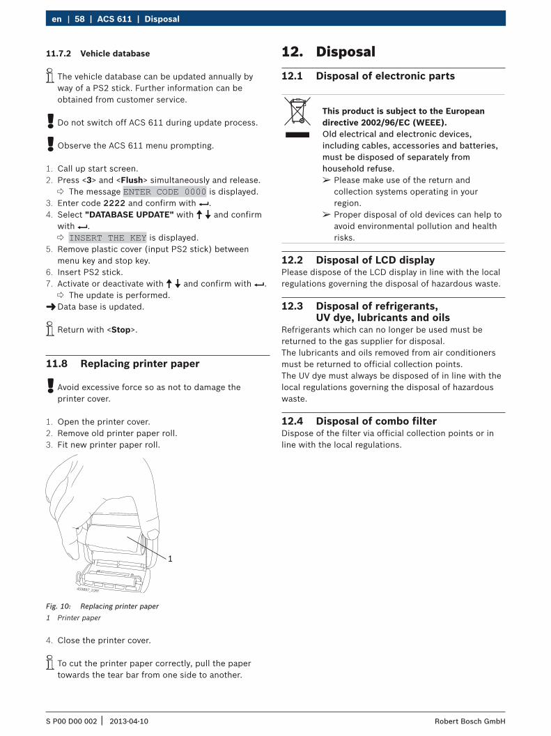
11.8 Replacing printer paper
! Avoid excessive force so as not to damage the printer cover.
1. Open the printer cover.2. Remove old printer paper roll.3. Fit new printer paper roll.
459897_10Rf
1
Fig. 10: Replacing printer paper1 Printer paper
4. Close the printer cover.
i To cut the printer paper correctly, pull the paper towards the tear bar from one side to another.
12. Disposal12.1 Disposal of electronic parts
This product is subject to the European directive 2002/96/EC (WEEE).Old electrical and electronic devices, including cables, accessories and batteries, must be disposed of separately from household refuse.
¶ Please make use of the return and collection systems operating in your region.
¶ Proper disposal of old devices can help to avoid environmental pollution and health risks.
12.2 Disposal of LCD displayPlease dispose of the LCD display in line with the local regulations governing the disposal of hazardous waste.
12.3 Disposal of refrigerants, UV dye, lubricants and oils
Refrigerants which can no longer be used must be returned to the gas supplier for disposal. The lubricants and oils removed from air conditioners must be returned to official collection points.The UV dye must always be disposed of in line with the local regulations governing the disposal of hazardous waste.
12.4 Disposal of combo filterDispose of the filter via official collection points or in line with the local regulations.
11.7.2 Vehicle database
i The vehicle database can be updated annually by way of a PS2 stick. Further information can be obtained from customer service.
! Do not switch off ACS 611 during update process.
! Observe the ACS 611 menu prompting.
1. Call up start screen.2. Press <3> and <Flush> simultaneously and release.
The message ENTER CODE 0000 is displayed.3. Enter code 2222 and confirm with E. 4. Select "DATABASE UPDATE" with o u and confirm
with E. INSERT THE KEY is displayed.
5. Remove plastic cover (input PS2 stick) between menu key and stop key.
6. Insert PS2 stick. 7. Activate or deactivate with o u and confirm with E.
The update is performed. "Data base is updated.
i Return with <Stop>.
S P00 D00 002 2013-04-10| Robert Bosch GmbH
Technical data | ACS 611 | 59 en
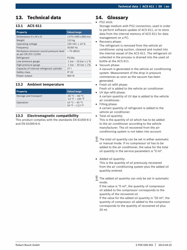
13. Technical data13.1 ACS 611
Property Value/range
Dimensions H x W x D 1270 x 690 x 660 mmWeight 110 kgOperating voltage 230 VAC ± 10 %Frequency 50/60 HzWorkplace emission sound pressure level as per EN ISO 11204
< 70 dB(A)
Refrigerant R134aLow-pressure gauge -1 bar – 16 bar ± 1 %High-pressure gauge -1 bar – 40 bar ± 1%Capacity of internal refrigerant cylinder 27 lSafety class IP 20Power output 800 W
13.2 Ambient temperature
Property Value/range
Storage and transport -25 °C – 60 °C -13 °F – 140 °F
Operation 10 °C – 45 °C 50 °F – 113 °F
13.3 Electromagnetic compatibility This product complies with the standards EN 61000-6-2 and EN 61000-6-4.
14. Glossary R PS2 stick:
Storage medium with PS2 connection; used in order to perform software update of ACS 611, or to store data from the internal memory of ACS 611 for data management on a PC.
R Recovery phase: The refrigerant is removed from the vehicle air conditioner using suction, cleaned and routed into the internal vessel of the ACS 611. The refrigerant oil collected in the process is drained into the used oil bottle at the ACS 611.
R Vacuum phase: A vacuum is generated in the vehicle air conditioning system. Measurement of the drop in pressure commences as soon as the vacuum has been generated.
R Fresh oil refill phase: Fresh oil is added to the vehicle air conditioner.
R UV dye refill phase: A certain quantity of UV dye is added to the vehicle air conditioner.
R Filling phase: A certain quantity of refrigerant is added to the vehicle air conditioner.
R Total oil quantity: This is the quantity of oil which has to be added to the air conditioner according to the vehicle manufacturer. The oil recovered from the air-conditioning system is not taken into account.
i The total oil quantity can be set in either automatic or manual mode. If no compressor oil has to be added to the air conditioner, the value for the total oil quantity in the service parameters is "0 ml".
R Added oil quantity: This is the quantity of oil previously recovered from the air conditioning system plus the added oil quantity entered.
i The added oil quantity can only be set in automatic mode. If the value is "0 ml", the quantity of compressor oil added to the compressor corresponds to the quantity of the recovered oil. If the value for the added oil quantity is "20 ml", the quantity of compressor oil added to the compressor corresponds to the quantity of recovered oil plus 20 ml.