advanced integrated electric traction system · pdf filethis presentation does not contain any...
TRANSCRIPT
This presentation does not contain any proprietary, confidential, or otherwise restricted information
Advanced Integrated Electric Traction System
Greg S. SmithGeneral Motors
May 22, 2009
Project ID: ape_09_smith
1
This presentation does not contain any proprietary, confidential, or otherwise restricted information
OverviewTimeline
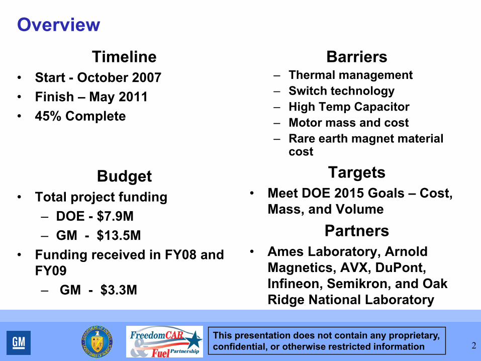
• Start - October 2007• Finish – May 2011• 45% Complete
Budget• Total project funding
– DOE - $7.9M– GM - $13.5M
• Funding received in FY08 and FY09– GM - $3.3M
Barriers– Thermal management– Switch technology– High Temp Capacitor– Motor mass and cost– Rare earth magnet material
cost
Targets• Meet DOE 2015 Goals – Cost,
Mass, and VolumePartners
• Ames Laboratory, Arnold Magnetics, AVX, DuPont, Infineon, Semikron, and Oak Ridge National Laboratory
2
This presentation does not contain any proprietary, confidential, or otherwise restricted information 3
Project Objective for FY08 – FY11• Develop and demonstrate advanced technologies for an
integrated ETS capable of 55kW peak power for 18 seconds and 30kW of continuous power.
• Meet DOE 2015 Targets– ETS that can accommodate a variety of automotive platforms
and the design should be scalable to 120kW peak power for 18 seconds and 65kW of continuous power.
– The ETS is to cost no more than $660 (55kW at $12/kW) to produce in quantities of 100,000 units per year, should have a total weight less than 46kg, and have a volume less than 16 liters.
– The cost target for the optional Bi-Directional AC/DC Converter is $375.
– The goal is to achieve these targets with the use of engine coolant at a nominal temperature of 105C.
– The system efficiency should exceed 90% at 20% of rated torque over 10% to 100% of maximum speed.
This presentation does not contain any proprietary, confidential, or otherwise restricted information
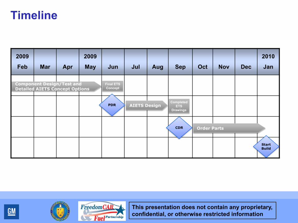
Timeline
2009
Feb Mar Apr
2009
May Jun Jul Aug Sep Oct Nov Dec
2010
Jan
Component Design/Test and Detailed AIETS Concept Options
AIETS DesignPDRCompleted
ETS Drawings
Final ETS Concept
CDR Order Parts
Start Build
This presentation does not contain any proprietary, confidential, or otherwise restricted information
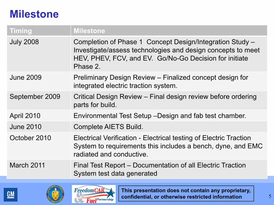
MilestoneTiming Milestone July 2008 Completion of Phase 1 Concept Design/Integration Study –
Investigate/assess technologies and design concepts to meet HEV, PHEV, FCV, and EV. Go/No-Go Decision for initiate Phase 2.
June 2009 Preliminary Design Review – Finalized concept design for integrated electric traction system.
September 2009 Critical Design Review – Final design review before ordering parts for build.
April 2010 Environmental Test Setup –Design and fab test chamber.June 2010 Complete AIETS Build.October 2010 Electrical Verification - Electrical testing of Electric Traction
System to requirements this includes a bench, dyne, and EMC radiated and conductive.
March 2011 Final Test Report – Documentation of all Electric Traction System test data generated
5
This presentation does not contain any proprietary, confidential, or otherwise restricted information 6
Technical Approach for FY09 and Beyond
• Use results of Phase I technology investigations and assessments and execute Phase II Development/Demonstration
• Phase II Development/Demonstration (8/08 – 5/11) – Develop detailed design of an Advanced Integrated ETS
• Work closely with suppliers• Applying learning from GM’s electrification experience
– Build Advanced Integrated ETS and characterize• Prove the viability of the technologies through 7 tests
designed to assess hardware performance for temperature, vibration, and EMC

This presentation does not contain any proprietary, confidential, or otherwise restricted information 7
Accomplishment – Vehicle Flexibility
“P1” “P2” “P3” “P4”
Off-Axle AWD Unit
Volume available for power electronics 2l- –3l and not necessary continuous. No dedicated motor housing or gearbox required
Volume available for motor 5l- –6l
Vehicle Electric Drive Implementations
To maximize number of platforms for ETS we considered all potential vehicle implementations
This presentation does not contain any proprietary, confidential, or otherwise restricted information
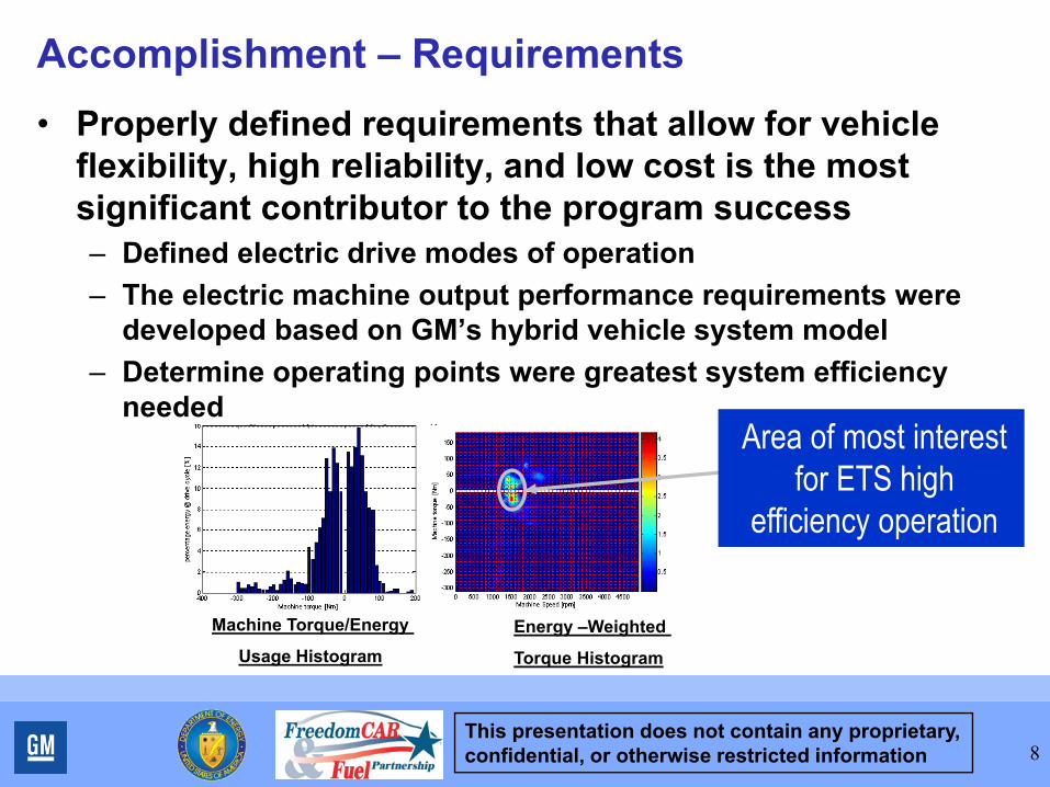
Accomplishment – Requirements• Properly defined requirements that allow for vehicle
flexibility, high reliability, and low cost is the most significant contributor to the program success– Defined electric drive modes of operation– The electric machine output performance requirements were
developed based on GM’s hybrid vehicle system model– Determine operating points were greatest system efficiency
needed
8
Machine Torque/Energy
Usage HistogramEnergy –Weighted
Torque Histogram
Area of most interest for ETS high
efficiency operation

This presentation does not contain any proprietary, confidential, or otherwise restricted information
Accomplishment – Trade Study• Established common
requirement baseline and ETS operating points for evaluation.
• Established the major criteria and sub-criteria to be used for scoring. Set scoring scale for each sub-criteria.
• Performed Pair-wise weighting• Built necessary cost, volume,
weight models• Ran Simplorer and motor
models to quantify performance criteria.
• Used consensus method to score non-quantifiable criteria.
9
This presentation does not contain any proprietary, confidential, or otherwise restricted information
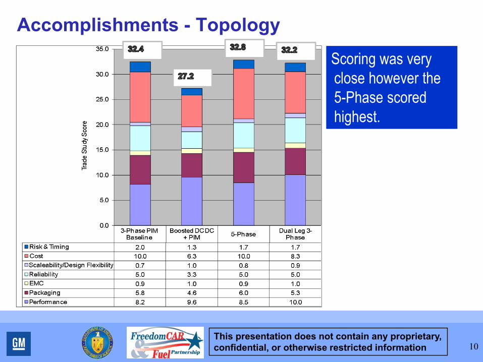
Accomplishments - Topology
10
Scoring was very close however the 5-Phase scored highest.
This presentation does not contain any proprietary, confidential, or otherwise restricted information
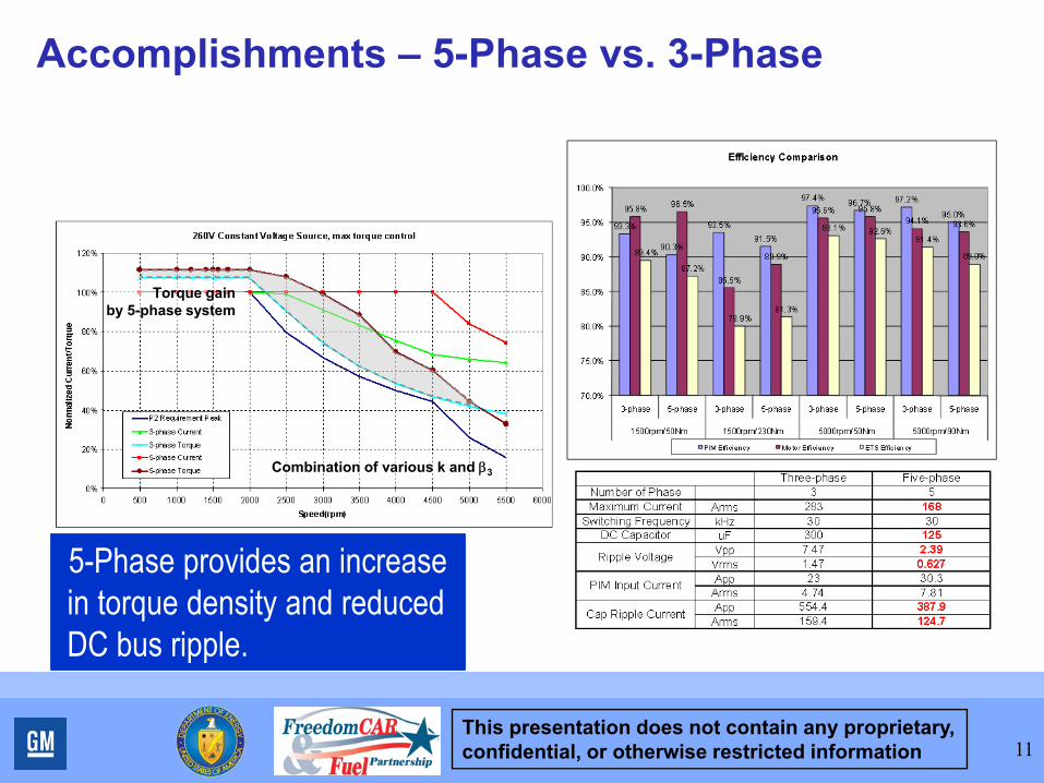
Accomplishments – 5-Phase vs. 3-Phase
11
5-Phase provides an increase in torque density and reduced DC bus ripple.
Combination of various k and β3
Torque gainby 5-phase system
This presentation does not contain any proprietary, confidential, or otherwise restricted information
Accomplishment - Multi-Phase Summary1. Multi-Phase machine can deliver more torque with same current than the
baseline 3 Phase system.• Multi-phase machine does not have 5th and 7th order torque ripple, which enables the
machine design without skew. Therefore, it is possible to deliver more torque and less ripple with same current level.
2. 6-Phase concentric-winding IPM can deliver 12% more torque than the distributed-winding baseline system theoretically (assuming 16.5% of harmonic rotor flux density by PM).
• 9.8% comes from winding structure, and 2% comes from harmonic current injection
3. 5-Phase system can use same tools developed for 6-phase.• 5-phase does not require additional power electronics for harmonic current generation.
At the same time, it has to control harmonic current to maintain the control, and its optimal solution for entire speed range is not derived yet.
4. 5-Phase system delivers comparable performance in loss, and gives less stress on passive components.
• Multi-phase system can carry more switching loss due to increased number of switching per cycle. However, due to the distribution of PIM losses, thermal performance can get better.
12
The 5-phase topology shows intriguing possibilities.
This presentation does not contain any proprietary, confidential, or otherwise restricted information
Accomplishment - Components• Developed two distinctive power module solutions
– Advance silicon• Integrated temp and current sense• Chips solderable on both sides
– Next generation of joint technology– Simplified interconnect technology
• Capacitor capable of meeting high temp environment using polypropylene film– Improve resin– Attachment of bus bar to capacitor– Matching capacitor to drive cycle
• Improved board technology for high temp environment using PWB technology
13
This presentation does not contain any proprietary, confidential, or otherwise restricted information
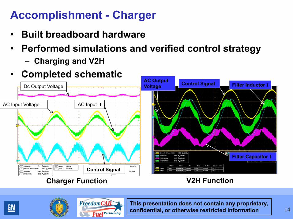
Accomplishment - Charger• Built breadboard hardware• Performed simulations and verified control strategy
– Charging and V2H• Completed schematic
14
Charger Function V2H Function
Dc Output Voltage
AC Input Voltage AC Input I
Control Signal
AC Output Voltage Control Signal Filter Inductor I
Filter Capacitor I
This presentation does not contain any proprietary, confidential, or otherwise restricted information 15
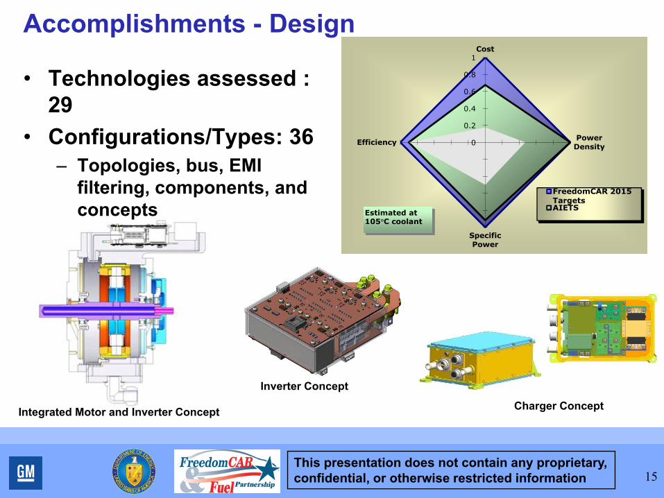
Accomplishments - Design
• Technologies assessed : 29
• Configurations/Types: 36– Topologies, bus, EMI
filtering, components, and concepts
Inverter Concept
Integrated Motor and Inverter Concept
0
0.2
0.4
0.6
0.8
1Cost
Power Density
Specific Power
Efficiency
FreedomCAR 2015 TargetsAIETS
Estimated at 105°C coolant
Charger Concept

This presentation does not contain any proprietary, confidential, or otherwise restricted information 16
Future Work• FY09
– Complete component testing– Finalize test plan for ETS– Finalize Design for AIETS
• Preliminary Design Review• Critical Design Review
• FY10– Build AIETS prototypes– Begin characterization testing of AIETS
• FY11– Complete characterization testing of AIETS– Verification Tests with Government Lab
This presentation does not contain any proprietary, confidential, or otherwise restricted information
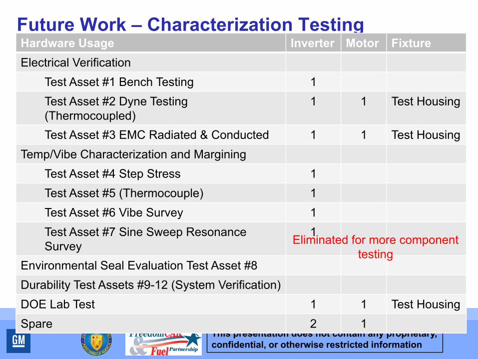
Future Work – Characterization TestingHardware Usage Inverter Motor FixtureElectrical Verification
Test Asset #1 Bench Testing 1Test Asset #2 Dyne Testing (Thermocoupled)
1 1 Test Housing
Test Asset #3 EMC Radiated & Conducted 1 1 Test HousingTemp/Vibe Characterization and Margining
Test Asset #4 Step Stress 1Test Asset #5 (Thermocouple) 1Test Asset #6 Vibe Survey 1Test Asset #7 Sine Sweep Resonance Survey
1
Environmental Seal Evaluation Test Asset #8Durability Test Assets #9-12 (System Verification)DOE Lab Test 1 1 Test HousingSpare 2 1
Eliminated for more component testing
This presentation does not contain any proprietary, confidential, or otherwise restricted information 18
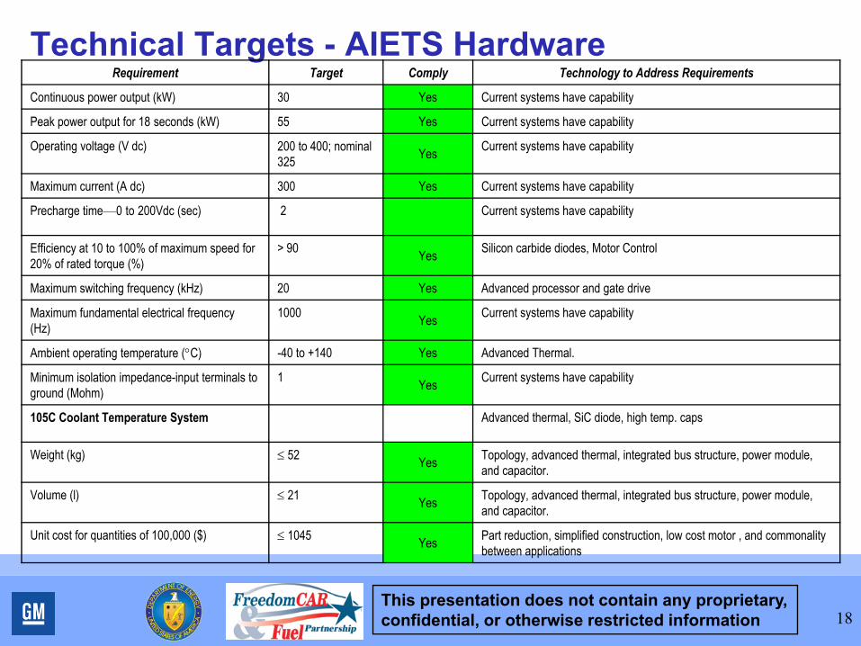
Technical Targets - AIETS HardwareRequirement Target Comply Technology to Address Requirements
Continuous power output (kW) 30 Yes Current systems have capability
Peak power output for 18 seconds (kW) 55 Yes Current systems have capability
Operating voltage (V dc) 200 to 400; nominal 325 Yes Current systems have capability
Maximum current (A dc) 300 Yes Current systems have capability
Precharge time—0 to 200Vdc (sec) 2 Current systems have capability
Efficiency at 10 to 100% of maximum speed for 20% of rated torque (%)
> 90 Yes Silicon carbide diodes, Motor Control
Maximum switching frequency (kHz) 20 Yes Advanced processor and gate drive
Maximum fundamental electrical frequency (Hz)
1000 Yes Current systems have capability
Ambient operating temperature (°C) -40 to +140 Yes Advanced Thermal.
Minimum isolation impedance-input terminals to ground (Mohm)
1 Yes Current systems have capability
105C Coolant Temperature System Advanced thermal, SiC diode, high temp. caps
Weight (kg) ≤ 52 Yes Topology, advanced thermal, integrated bus structure, power module, and capacitor.
Volume (l) ≤ 21 Yes Topology, advanced thermal, integrated bus structure, power module, and capacitor.
Unit cost for quantities of 100,000 ($) ≤ 1045 Yes Part reduction, simplified construction, low cost motor , and commonality between applications

This presentation does not contain any proprietary, confidential, or otherwise restricted information
SummaryGeneral Motors is applying a systems approach to the
ETS and how it is used in vehicle applications– Clearly identifying system requirements are key factor in
program success– Must understand factors that influence system performance and
reflect into trade study criteria• Modes of operation in vehicle drive cycle• Environment
– Trade study shows that topology winners dependent on system operation strategy
– Hardware design needs to be flexible to address vehicle applications
• PHEV, HEV, FCV, and EV• Power level• Environment
19