aircraft power plants_2ed
DESCRIPTION
Aircraft Power Plants_2EdTRANSCRIPT

V. F. Shmyrov, R. U. Tsukanov, A. I. Ryzhenko, V. D. Pehterev
В. Ф. Шмирьов, Р. Ю. Цуканов, О. І. Риженко, В. Д. Пехтєрєв
AIRPLANE POWER PLANTS SYSTEMS DESIGNING
ПРОЕКТУВАННЯ СИСТЕМ СИЛОВИХ
УСТАНОВОК ЛІТАКІВ
2011

MINISTRY OF EDUCATION AND SCIENCE OF UKRAINE N. Ye. JOUKOWSKI NATIONAL AEROSPACE UNIVERSITY
«Kharkiv Aviation Institute»
МІНІСТЕРСТВО ОСВІТИ І НАУКИ УКРАЇНИ Національний аерокосмічний університет ім. М. Є. Жуковського
«Харківський авіаційний інститут»
V. F. Shmyrov, R. U. Tsukanov, A. I. Ryzhenko, V. D. Pehterev
AIRPLANE POWER PLANTS SYSTEMS DESIGNING Synopsis
В. Ф. Шмирьов, Р. Ю. Цуканов, О. І. Риженко, В. Д. Пехтєрєв
ПРОЕКТУВАННЯ СИСТЕМ СИЛОВИХ УСТАНОВОК ЛІТАКІВ Конспект лекцій
Kharkiv «KhAI» 2011

UDK 629.735
Airplane Power Plants Systems Designing: synopsis / V. F. Shmyrov, R. U. Tsukanov, A. I. Ryzhenko, V. D. Pehterev. — Kharkiv: National Aero-space University «KhAI», 2011. — 220 с.
Aircraft power plant systems design methods, such as engine mount,
shock absorption, fuel system, lubrication system design and analysis are stated. Necessary information about power plant internal aerodynamics, sub-sonic and supersonic air intakes and exhaust units is given. Wide outlook of aircraft power plant development is given. This information is minimally re-quired for passing exam on the course «Airplane Power Plant System Design-ing». The book can be useful for students to carry out the course and diploma projects. Data and information appearing in this book are for educational pur-poses only.
This synopsis is intended for students studying for major subject «Aero-space Engineering». Fig. 206. Tab. 6. Bibliography: 56 names
The reviewers: ScD, Prof. Aleksey B. Leontiev, ScD, Prof. Boris V. Lupkin
Проектування систем силових установок літака: консп. лекцій / В. Ф. Шмирьов, Р. Ю. Цуканов, О. І. Риженко, В. Д. Пехтєрєв. — Х.: Нац. аерокосм. ун-т «ХАІ», 2011. — 220 с.
Викладено методи проектування систем силових установок літаків, а саме: конс-
труювання й розрахунок систем кріплення двигунів та їх амортизації, паливних і масля-них систем. Наведено необхідні відомості про внутрішню аеродинаміку силових уста-новок (СУ), дозвукові й надзвукові повітрозабірники, а також вихідні пристрої СУ. Дано широкий огляд перспектив розвитку силових установок найрізноманітніших літальних апаратів. Дані та інформація, наведені у книзі, призначено виключно для цілей навчан-ня.
Для студентів, що навчаються за напрямком «Авіа- та ракетобудування», при підготовці до складання іспиту з дисципліни «Проектування систем силових установок літаків», а також при виконанні курсових і дипломних проектів. Іл. 206. Табл. 6. Бібліогр.: 56 назв
Рецензенти: д-р техн. наук, проф. О. Б. Леонтьєв, д-р техн. наук, проф. Б. В. Лупкін
© Національний аерокосмічний університет ім. М. Є. Жуковського «Харківський авіаційний інститут», 2011 р.

3
PREFACE
The task of up–to–date aircraft designing includes extensive complex of related problems. It is necessary to satisfy the requirements of aerodynamics and flight dynamics, strength and stiffness, reliability and survivability, repair-ability and, the main, effectiveness. Recently, different versions of economic ef-ficiency criterion are frequently used as the main optimization criterion both for civil and military aircraft. A number of factors directly effecting on economic ef-ficiency of created or operated aircraft are related to power plant designing so-lutions.
Rational choice of type and number of engines, their model and arrange-ment on aircraft significantly effects on following all main requirements to the designed aircraft and often even to realizability of new aircraft (e. g. verti-cal/short take-off and landing (VTOL/STOL) aircraft, stealth aircraft and micro aviation aircraft).
Without understanding basic laws of working process of aviation gas-turbine engines and factors which influence on engine parameters selection, understanding of working processes in engine main units, conditions of their combined action, engine performance, engine systems operation, basic princi-ples of their automatic control, propellers performance and structural fea-tures — it is impossible to select engine rationally and to match performances of power plant and aircraft.
Engine mount scheme selection rationality and its parameters choice cor-rectness impact not only to strength and stiffness, but also allow to eliminate resonance, discomfort condition for passengers onboard, increased crew fati-gability, fast equipment wear; provide maintainability and repairability; and as a result impact to profit brought by aircraft and its competitiveness.
Fuel system designing quality directly impacts to reliability and fire danger of power plant, direct and indirect aircraft maintenance expenses, for example, due to greater or less mass of unusable fuel, required fuelling time etc.

4
Air intake designing significantly impacts on aircraft aerodynamic per-formance, engine efficiency, unprepared airfield basing capability, aircraft ma-neuverability and many others important properties of created airplane and aviation complex as a whole…
Competently designed exhaust arrangement significantly improves ma-neuverability performance of created airplane by means of thrust vectoring ap-plication, decrease aircraft observability in infrared spectrum, and also noise, produced by jet stream, — important characteristic of airplanes both military, and civil application. Therefore, great attention is paid to studying the course «Airplane Power Plant System Designing», its full and up–to–date methodical support.
This publication contains the synopsis for the lecture course «Airplane Power Plant System Designing», which is taught for the fourth course students, being studying for the major subject «Aerospace Engineering». The synopsis includes 11 themes, which are intended to power plant arrangement and classi-fication, engine mount and its shock-absorption, fuel and lubricant systems, in-ternal aerodynamics, subsonic and supersonic air intakes designing, exhaust units and power plants outlook.
With the brevity purpose, we use two techniques within this synopsis: when the difference is insufficient, instead «turbojet and bypass turbojet» we write «(bypass) turbojet»; and we use «[+]» sign to mark advantage and «[–]» sign to mark disadvantage correspondingly.
This synopsis can be useful for the fullest understanding of information given at lectures for students independent studying of some questions, when preparing to laboratory work passing, when doing course and diploma projects and also bachelor papers.
Authors acknowledge to all, who helped them in material collection and in writing the book, and especially to Victor P. Ishchuk, Valeriy M. Smirnov, Yuri V. Hodzitskiy, Anatoliy I. Gorbenko, Vadislav I. Lianenko.
5
Theme 1. INTRODUCTION TO COURSE «AIRCRAFT POWER PLANT SYSTEMS DESIGNING»
1.1. Subject of Discipline. Definition of Concept Power Plant. Purpose of Aircraft Power Plant
Aircraft power plants (ENG) are intended for creation of thrust force, pro-vision of energy for some systems, and also for solution of special problems.
Power plants are set of engines and systems providing their operation on all operational modes (Flight Mach number M, altitude Н, temperature T ets.), allowable for an aircraft.
Subject of the discipline «Aircraft power plant systems designing» are functionality, design features, arrangement, analysis of operation, methods of designing of systems and equipment of aircraft power plants.
Power plant consists of: main and auxiliary engines and systems provid-ing their operation:
– propeller and propeller spinner installation (onto piston engines, turbo-prop engines and prop-fan engines);
– fuel system (to feed engine by fuel and fuel storage on an aircraft); – lubrication system (to provide of friction surface lubrication and heat re-
jection from units of power plant); – engine mount (for reliable attachment of engine with the units installed
on it (i.e. pumps, generators, cowlings) to attachment fittings of an aircraft structure);
– air ingestion system (air intakes with its ducts); – exhaust system with a device of thrust reverse, with noise suppression
devices; – cooling system for engines and their power plant units; – control system of engines and other power plant systems; – starting system; – fire protection system; – deicing system; – cowling system (engine nacelles and cowlings); – special systems; – auxiliary power plant (APU).
1.2. Aviation power plant improvement directions A number of ways are used for increase of speed, range and flight alti-
tude, load-carrying capacity and also for improvement of characteristics of air-craft take-off and landing.
1. Required thrust force P measured in [N], [kg], [daN], or power N measured in [W], [h.p.], [kw] of power plant.

6
As it is known, the maximum flight speed is determined by formulas: for (bypass) turbojets: HxaMAX SCP2V ρ= , for piston engines and turboprops:
3 HxapMAX SCN2V ρη= . Cruising flight altitude, ceiling and zoom altitude, ma-neuverability performance, payload, runway length are defined in the first place by available thrust of engines installed in aircraft.
Now, the highest achievements for various engine types are the following: for GE90-115B turbojet engine —thrust is 513950 N; for NK-12 turboprop engine —power is 11000 kw: for VD-4K piston engine — power is 3160 kw. 2. Minimal specific gravity of engine (ratio of the engine weight to its
thrust force or to its power) – for turbojet: Pgmenen ⋅=γ – or for piston and turboprop: Ngmenen ⋅=γ [daN/kw], [kg/h.p.]. Now1, the highest achievements for various engine types are the follow-
ing: for piston engines is 31670en .....=γ [daN/kw]; for turboprop engines is 330270en .....=γ [daN/kw]; for turbojets is 25020en .....=γ ; for turbojets with afterburner is 20150en .....=γ ; for bypass turbojets2 is 2201650en .....=γ ; for bypass turbojets with afterburner is 15010en .....=γ ; for VTOL lifting engines 10en .=γ . 3. Minimal relative mass of power plant and fuel (ratio of mass of power
plant (fuel) to take-off mass of the airplane)
0enPPen
0
0
0
enPPen
0
enPPen
0
PPPP tkn
gmP
Pgmkn
mmkn
mmm γ=⎟⎟
⎠
⎞⎜⎜⎝
⎛⎟⎟⎠
⎞⎜⎜⎝
⎛=== ...
..
;
0
FF m
mm =,
Type of aircraft PPm . Fm Subsonic passenger and transport 0.08...0.14 0.18...0.40
Maneuverable 0.18...0.22 0.25...0.30
where gmPt 000 = — thrust/weight ratio of airplane, enn — number of en-gines; PPk . — ratio of weight of power plant to weight of engines ( 2221k PP ...... = ). 1 For comparison, Mozhaisky airplane steam engines had 710en .=γ [daN/kw]. 2 The most powerful turbojet in the world GE90-115B has 1670en .=γ .
7
4. Minimal specific fuel consumption (the mass of fuel necessary for crea-tion a unit of thrust (power) at one hour). For the most powerful engines it makes.
pC , ⎥⎦⎤
⎢⎣⎡
⋅hourNkg
eC , ⎥⎦⎤
⎢⎣⎡
⋅hourkwkg
Engine
0.033 — GE90-115B — 0.224 NK-12 — 0.251 VD-4K
0.0662 — D-36 Just specific fuel consumption at cruising mode in the first place defines
airplane economical efficiency and significantly impacts on quantity of harmful emission to atmosphere.
5. Good aerodynamic characteristics: – Minimal aerodynamic drag, created by power plant and minimal impact
pressure losses due to optimal engine air intakes, radiators, cooling systems designing;
– Optimal propeller shape and propeller control; – Optimal nozzle shape and nozzle control (for supersonic aircraft and for
aircraft with thrust vectoring); – Optimal performance of thrust reverse devises.
1.3. Over-all Technical Requirements to Aircraft Power Plants 1. Provision of desired flight performance of an aircraft ( maxL , maxV , ceilH ,
zoomH , maxt , lpm . ...). 2. Provision of reliability, safety and survivability of power plant. (That is,
reliability, safety and survivability must be provided at all operational modes of power plant in all conditions allowable for an aircraft).
3. Provision of necessary strength and vibration damping of attachment of the engine, units of power plant, nacelles, cowlings.
4. Maintainability, testability, repairability. (That is, convenience of main-tenance, of ground test and in–flight test, a little time required for replacement of a faulty unit or engine).
5. Minimal negative effect to environment. (Noise level and engine emis-sion must match to standards [3]. Noise level and vibrations in cabin should be minimal.)
6. Protection of power plant against birds, dust and foreign matter from ground (dust filters on air intakes of piston engines, cut-off air streams, grids, upper air intakes on MiG-29).
7. Provision of high service life of power plant systems. 8. General requirements to all parts of an aircraft — minimal mass and
overall dimensions. 9. Minimal cost of power plant life cycle (designing + manufacturing +
testing + storage + operation + maintenance + repair + salvaging).

8
Checklist 1. What is the purpose of aviation power plant? 2. What is aviation power plant? 3. What is the subject of the discipline «Aircraft power plant systems de-
signing»? 4. List what is included in aviation power plant. 5. In what way does the maximum speed of horizontal flight depend on
power plant thrust (power)? 6. What are the maximum achieved thrust (power) values for various en-
gine types? 7. What is specific gravity of engine? What measurement units are used
for it? 8. What are the achieved values of specific gravity for various engine
types? 9. How to express relative mass of power plant through specific gravity
of engine and thrust/weight ratio of airplane? 10. What are the achieved values of relative mass of power plant and
fuel? 11. What is specific fuel consumption? What measurement units are used
for it? 12. What are the achieved values of specific fuel consumption for various
engine types? 13. Make examples of power plant aerodynamic performance impact on
airplane flight performance. 14. How to provide reliability, safety and survivability of power plant? 15. What is maintainability of power plant? 16. Make examples of power plant negative influence onto environment. 17. List power plant life cycle stages.

9
Theme 2. CLASSIFICATION OF POWER PLANTS. TYPES OF AIRCRAFT ENGINES AND THEIR ARRANGEMENT ON AIRCRAFT
Aircraft power plants can be classified by: engines type; number of en-gines, their arrangement on the aircraft etc.
2.1. General Analysis of Aircraft Engine Types and Areas of Their Application
2.1.1. Piston Engines Before the second half of 40th years the main aircraft engines were piston
engines. Now after temporary liking for jet engines, piston engines find wide application again in general aviation (executive, trainer, agricultural, acrobatic aircraft) and also for unmanned air vehicles (UAV) of various masses and sizes (ref. Theme 11).
They together with propellers form so called propeller–engine installation (ВМУ).
Piston engines are divided into air-cooled engines and water-cooled en-gines. Air–cooled engine is a casing with radially arranged cylinders. Otherwise they are called radial engines (Fig. 2.1, а). For greater uniformity of rotation the number of cylinders is usually odd (3, 5, 7, 9...). When the number of cylinders required for desired power, is not arranged within one plane, they are arranged in some rows. There are one-, two- and four-row radial engines.
Water–cooled engine is a casing with cylinder blocks, arranged in a line (with 2...8 cylinders in a line). By arrangement of these blocks on the front view, they are distinguished, V-shaped (Fig. 2.1, b), Y-shaped, X-shaped, H-shaped and opposed piston engines. For cooling these engines, liquid is used. This liq-uid is usually water. But at negative temperature special antifreeze is used. This liquid is then cooled in the special air–water cooler. Such engines are also called in–line engines.
a b
Fig. 2.1. Piston Engines (а — Radial, b — In–Line)

10
It is typical for piston engines: [+] High efficiency 30250Ce .....= [kg/kw⋅hour]; [+] High reliability, simplicity in maintenance, refined design; [+] Compactness of power plant arrangement; [–] High specific gravity 31670en .....=γ [kg/kw]; [–] Impossibility to achieve high speed. The matter is that thrust developed by power plant with propeller, is equal
to VNP pea η= , where eN — effective power of engine;
pη — efficiency of propeller; V — flight speed. As the effective power of piston engines does not depend on flight speed, and the efficiency of the propeller drops with approaching to sonic speed, then the thrust force developed by the power plant with a propeller decreases at the flight speed grows. At the same time, aerodynamic drag (required thrust) sharply increases.
2.1.2. Turboprop Engines At the moderated subsonic flight speed ( 8060M .....< ) and moderated
flight altitude (6000...10000 m) turboprop engines (Fig. 2.2) have broad applica-tions.
Turboprop engines have the following properties: [+] Capability to obtain a high-power in one unit (NK-12 — 11000 kw); [+] Small specific gravity ( 330270 ..... [daN/kw]); [+] Small area of a mid-section, in comparison with piston engines; [+] Specific fuel consumption is less, than at turbojet
( 40330Ce .....= [kg/kw⋅hour]); [–] Specific fuel consumption is more, than at piston engines; [–] Speed limitation because of a propeller;
Fig. 2.2. Scheme of Turboprop Engine:
1 — Propeller; 2 — Reduction Gear; 3 — Compressor; 4 — Combustion Cham-ber; 5 — Turbine; 6 — Jet Nozzle
[–] Specific gravity and the cost of maintenance is more, than at turbojet; [–] Limitations of arrangement, because of a propeller. Prop-fan engines differ from turboprop engines only by propeller
(Fig. 2.3). The propeller of a prop-fan engine is optimized for high subsonic

11
flight speed ( 95080M .....= ). It has high efficiency at such flight speed. Such propellers usually have broad scimitar-type blades. It reduces aero-dynamic drag of rotated blade when the supersonic speed is reached on the blade tip. Usage of such propellers allows to decrease specific fuel con-sumption by 15-20% as well as noise and vibration into cabin.
2.1.3. Turbojets To reach higher (including su-
personic) speed is possible by means of turbojet (Fig. 2.4). It is considered, that specific thrust (the ratio of engine thrust to air consumption through it) of turbojet becomes more, and the specific fuel consumption — less, than turboprop has at speed over 800 km/h. Turbojet is a direct reaction engine, that integrates an engine and a propulsor (Engine is a machine transferring some kind of energy to mechanical work. Propulsor is a devise providing movement.) in one unit (at piston engine and turboprop the propulsor is a propeller). Now, turbojets are practically excluded by more effi-cient by–pass turbojet engines from application at both civil and combat air-craft.
Fig. 2.4. Scheme of Turbojet:
1 — Air Intake; 2 — Compressor; 3 — Combustion Chamber; 4 — Turbine; 5 — Jet Nozzle
Turbojet has: [+] Small specific gravity (0.2...0.25); [+] Small overall dimensions; [+] High thrust (60...51395 [daN]); [+] Convenience of arrangement (because of absence of a propeller); [–] Big specific fuel consumption ( 9070Cp .....= [kg/daN⋅hour]); [–] High noise level.
Fig. 2.3. Prop-Fan Engine
12
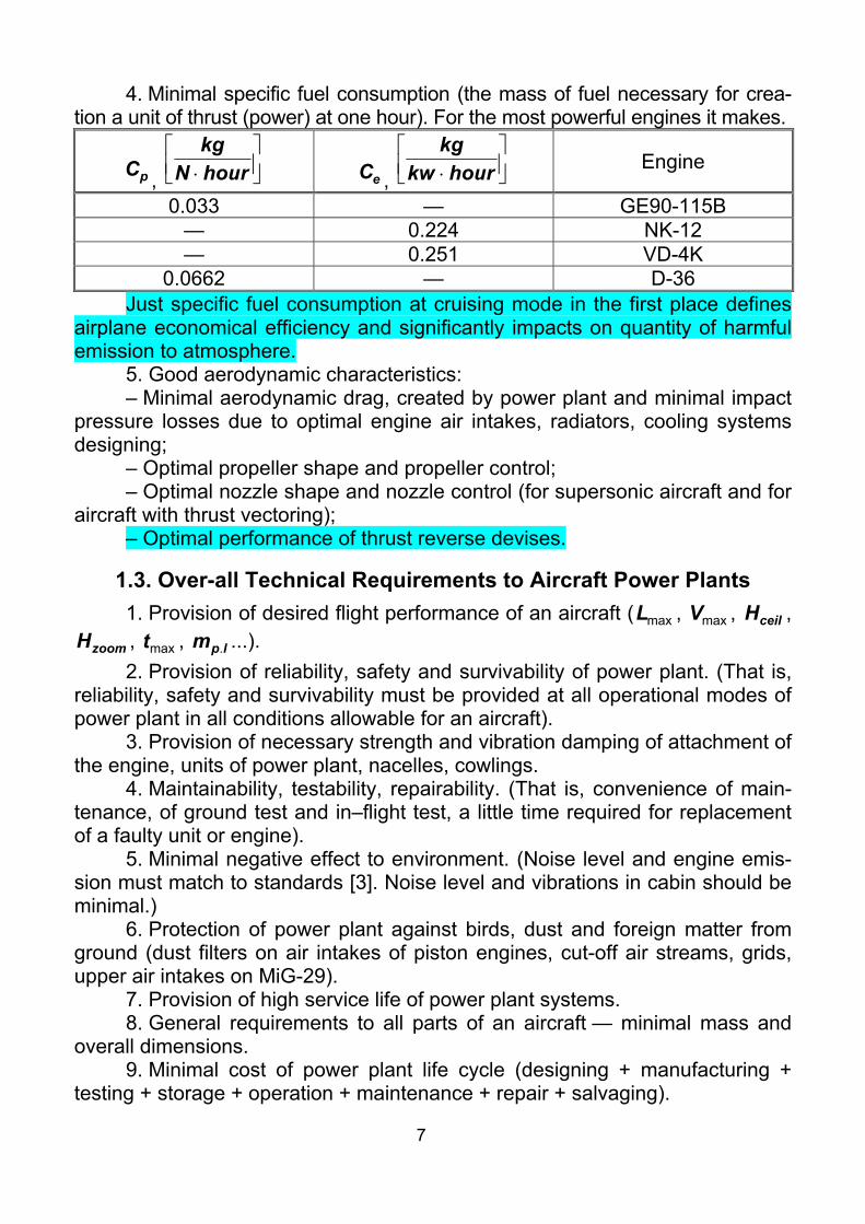
2.1.4. Bypass Turbojets At transonic and moderated supersonic flight speed the bypass turbojets
(Fig. 2.5) are the most efficient. The bypass engines differ from turbojets by presence of the second (external) contour, air flows around of the combustion chamber and turbines by which. Then this air mixes with combustion products of the first contour. Thus the air consumption increases and speed of jet stream decreases.
Turboprop accelerates the big air consumption up to a low speed. Turbo-jet accelerates the small air consumption up to a high speed. Bypass turbojet takes an intermediate place between them. A fan of the bypass turbojet is a version of propeller in a ring channel.
Bypass turbojets are characterized by bypass ratio. It is a ratio of an air consumption through an external (air, cool or second) contour to an air con-sumption through an internal (gas, hot or first) contour
1
2
mmm = .
Fig. 2.5. Scheme of Bypass Turbojet:
a — Bypass Turbojet Without Mixing; B — Bypass Turbojet With Mixing; 1 — Fan; 2 — High Pressure Compressor; 3 — Combustion Chamber;
4 — Shaft With High Pressure Turbine; 5 — Low Pressure Turbine; 6 — Jet Nozzle Of Air Contour; 7 — Jet Nozzle; 8 — Mixer
Bypass turbojets have the following advantages. 1. When bypass ratio is low ( 2m < ) the specific fuel consumption is usu-
ally 15...20 % less, than at turbojets. Such bypass turbojets are applied at su-personic flight speed. When 85m ...= the specific fuel consumption is usually 40...45 % less, than at turbojets. Such bypass turbojets are used at subsonic flight speed.
2. Bypass turbojets have lower noise levels (in comparison with turbo-jets). Because noise generated by gas stream sharply depends on speed dif-ference between gas stream and surrounding air. And the stream from the first contour (fast and noisy) is surrounded with a stream from the second contour (slow and less noisy).
Specific fuel consumption of bypass turbojets is low because of high thrust efficiency. Thrust efficiency is a ratio of effective thrust work (which is made by gas), to available kinetic energy of the gas stream
13
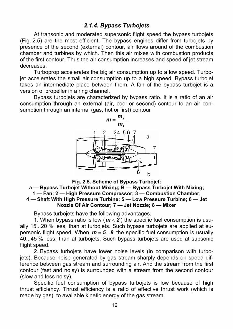
H
ST
VV1
2
+=η
, where SV — speed of a jet stream; HV — flight speed.
Thrust efficiency tends to one, when speed of the jet stream tends to flight speed from above. It happens in bypass turbojets with the big bypass ratio (Fig. 2.6). Such engines are sometimes called turbofan.
Fig. 2.6. Relation between Thrust Efficiency and Speed of Jet Stream
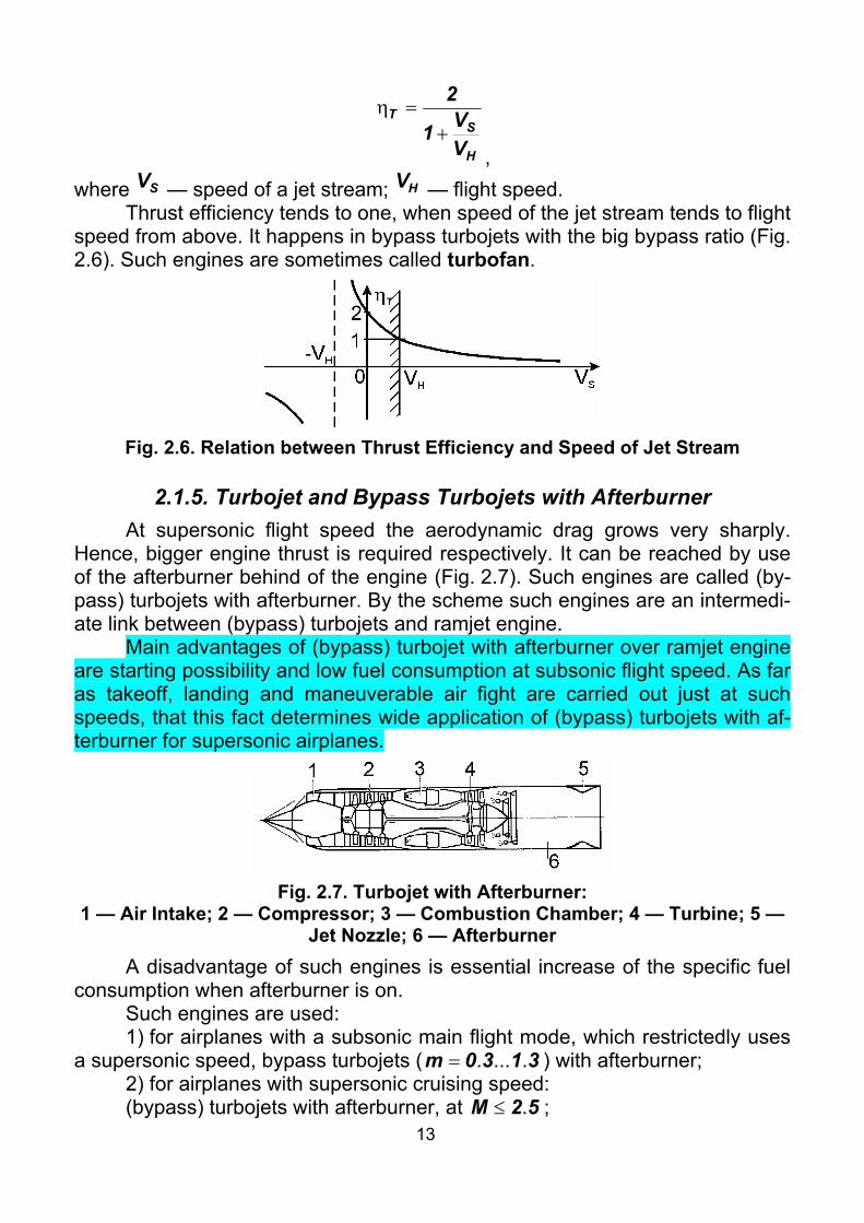
2.1.5. Turbojet and Bypass Turbojets with Afterburner At supersonic flight speed the aerodynamic drag grows very sharply.
Hence, bigger engine thrust is required respectively. It can be reached by use of the afterburner behind of the engine (Fig. 2.7). Such engines are called (by-pass) turbojets with afterburner. By the scheme such engines are an intermedi-ate link between (bypass) turbojets and ramjet engine.
Main advantages of (bypass) turbojet with afterburner over ramjet engine are starting possibility and low fuel consumption at subsonic flight speed. As far as takeoff, landing and maneuverable air fight are carried out just at such speeds, that this fact determines wide application of (bypass) turbojets with af-terburner for supersonic airplanes.
Fig. 2.7. Turbojet with Afterburner:
1 — Air Intake; 2 — Compressor; 3 — Combustion Chamber; 4 — Turbine; 5 — Jet Nozzle; 6 — Afterburner
A disadvantage of such engines is essential increase of the specific fuel consumption when afterburner is on.
Such engines are used: 1) for airplanes with a subsonic main flight mode, which restrictedly uses
a supersonic speed, bypass turbojets ( 3130m .....= ) with afterburner; 2) for airplanes with supersonic cruising speed: (bypass) turbojets with afterburner, at 52M .≤ ;

14
turbojets with afterburner, at 53M .≤ .
2.1.6. Ramjet Engines For flight speed, corresponding 53M .≥ the compressor is not needed. It
is possible to provide compression in the air intake. In such cases ramjet en-gines (Fig. 2.8) are appropriately used.
Fig. 2.8. Scheme of Ramjet Engine:
1 — Air Intake; 2 — Fuel Nozzles; 3 — Flame Stabilizer; 4 — Jet Nozzle They distinguish ramjet engines with subsonic combustion of fuel which
use at 8M < , and ramjet engines with supersonic combustion of fuel, which are used at higher speed.
Ramjet engines have: [+] Low specific gravity (approximately two times lower, than turbojets
have); [+] Simple design; [+] High efficiency at 51M .> ; [–] Need of acceleration up to 51M .= by engines of another type. On airplanes and helicopters, ramjet engines are not practically used, ex-
cept for experimental vehicles. Ramjet engines have found a broad application in supersonic cruise missiles.
2.1.7. Rocket Engines Rocket engine as a first approximation represents the combustion chamber with a jet nozzle (Fig. 2.9). They have not air intake. Fuel for rocket engines is onboard a vehicle. In this case the fuel is combustible and oxidizing agent. Rocket engines are divided into: liquid–propellant rocket engines (Fig. 2.9, a); solid–propellant rocket engines (Fig. 2.9, b); hybrid rocket engines (Fig. 2.9, c); nuclear rocket engines (Fig. 2.9, d); electro-rocket engines (Fig. 2.9, e). In avia-tion the first two types find restricted application.
Liquid-propellant rocket engines have: [+] Small engine weight (20...30 times less, than piston engine); [+] Small overall dimensions; [+] Independence of thrust on the flight altitude and speed; [+] Absence of air intakes; [–] Need of storage of oxidizing agent onboard the vehicle; [–] Higher specific fuel consumption (20...50 times more, than piston engine).

15
a b c d e
Fig. 2.9. Rocket Engines Solid-propellant rocket engines in addition to this have: [+] Simple structure of engine and fuel charge; [+] Long time of high availability to start; [+] Little start-up preparation time; [+] Small sizes of fuel charge, because of its high density
( 3261 ..... g/cm3); [–] Specific impulse 10…20 % less in comparison with liquid-propellant
rocket engine one; [–] Complexity of thrust control and cutoff; [–] Complexity of keeping constant thrust during operating time. Rocket engines are extremely seldom used in aviation: 1) as a rocket
booster during takeoff from a short runway; 2) as a rocket booster in fight. Last version of application of rocket engines is more likely property of a history, than practical use. Rocket engines have found the broadest application in rockets, including air and anti-aircraft.
2.1.8. Combined Engines To obtain a good engine performance in a broad range of altitudes and
flight speeds, now it is considered appropriate, a combination of two types of engines in one unit. Such engines are called combined engines or variable cy-cle engines:
– turbo–ramjet (Fig. 2.10); – turbo–rocket; – rocket–ramjet (Fig. 2.11). Such engines allow to take-off and land in turbojet or solid–propellant en-
gine mode, and cruise flight — in ramjet or liquid–propellant engine mode. This fact should increase flight range and provide acceptable characteristics of take-off and landing (if it is required).

16
Fig. 2.10. Combined Turbo–Ramjet Engine:
1 — Common Air Intake; 2 — Bypass Contour For Ramjet Engine; 3 — Turbojet Engine; 4 — Fuel Nozzle Manifold; 5 — Common Jet Nozzle
Fig. 2.11. Combined Rocket–Ramjet Engine
Now work is underway on creation of such engines for spaceplanes in the world. Another area of their application is rockets.
2.1.9. Combined Power Plants Combined power plants are power plants in which engines of different types
are used. They were used in days of transition from piston engines to turbojets. Now they are property of a history. But, it is known, the history is repeated.
For instances it is possible to remind: – (piston engines + turbojets): Convair B-36; Ryan FR-1 Fireball; Su-7
(first with this name); – (turbojets + liquid–propellant engines): SM-50 (version of MiG-19); E-50
(version of MiG-21); – (piston engines + solid–propellant engines): Me-323 Gigant. – (piston engines + ramjet engine): Yak-7 (prototype version).
2.1.10. Turboshaft Engines Turboshaft engines are very similar to turboprop. Only difference is a free
turbine behind the main turbine (Fig. 2.12). This free turbine is not linked me-chanically to the compressor. There is only gas-dynamical linkage. The effec-tive power of the engine is transmitted by the free turbine.
Fig. 2.12. Scheme of Turboshaft Engine
17
Such engines are widely used in helicopters. They have greater stability of operation under specific conditions of helicopters, in comparison with turbo-prop engines.
2.2. Auxiliary Power Unit Auxiliary power unit (APU) is intended generally: – To start the main engines on ground and in flight. – To supply an airplane with the electric power on ground and in flight in
emergency situation. – To maintain activity of air conditioning system on ground. Sometimes, in addition to these it is used for: – Emergency supply of a hydro system. – Creation of additional thrust (An–24/26; An–71). – Creation of required thrust under main engine fault (An-24/26). APU consists of the same systems as the main power plant consists: – Small gas-turbine engine; – Fuel system; – Lubrication system; – Engine mount; – Air intake system (it usually includes an air intake cover to reduce drag
in inoperative condition); – Exhaust system; – Control system; – Starting system; – Fire protection system; It is necessary to note, that some of the systems can be a part of systems
of main power plant (for example: fuel and fire protection systems). APU are usually located onboard of an aircraft in a sponson (Il–76,
An-124), or in an engine nacelle (An–24/26) or in a tail part of a fuselage (An–140, А-300, В-767). The main requirements to APU location are:
– Fire safety. – Not to disturb airframe of the assembly, which is located inside. – Convenience of maintenance.
2.3. Engine Selection The engine type selection is carried out depending on technical require-
ments to a designed aircraft. The areas of rational application of engines of various types are shown in Fig. 2.13. Here are designated areas of effective use for: 1 — piston engines; 2 — turboprops; 3 — bypass turbojets; 4 — turbo-jets; 5 — ramjet engines; 6 — rocket engines. A — area of insufficient wing lift. B — area of an inadmissible aerodynamic heating.
In Fig. 2.14 relative engine thrust dependences on Flight Mach number are shown. From the figure it is obvious that, it is impossible to reach sonic

18
speed by using piston engine or turboprop. It is seen too, that ramjet engine becomes effective at 51M .> .
Fig. 2.13. Application Areas of
Engines of Various Types Fig. 2.14. Dependences of Relative
Engine Thrust to Flight Mach number
а b
Fig. 2.15. Altitude-Airspeed Performance of By-pass Turbojet а — Thrust Dependence on Flight Mach number;
b — Thrust Dependence on Flight Altitude

19
Engine model selection is carried out by comparative analysis of altitude-airspeed performance, overall dimensions, mass and air consumption of sev-eral engines. In real designers bureau condition, as a rule, the new engine or its modification optimized for a new aircraft is created (for example D-30 en-gine, developed in 1966 for civil subsonic airliners Tu-134/154M, Il-62M/76, was modified to D-30F6 with afterburner and variable area jet nozzle in 1980 for MiG-31 heavy supersonic fighter). Fig. 2.15 shows typical altitude–airspeed performance of bypass turbojet.
2.4. Number of Engines One of the main requirements to up-to-date airplanes (with more than one
engine) is ability to continue take-off and climb when one engine has failed. Thus for good safety the vertical speed of climb and the flight path angle must be more then or equal to the specified values. These values depend on the type of airplane and are specified by requirements to the designed airplane. These values can influence on the number of engines installed onboard the airplane.
Equations for motion of an airplane at steady climb are known from a flight dynamics:
⎩⎨⎧
Θ=
Θ+=
,cos;sin
mgYmgXP
a
a
where P — thrust; aX — aerodynamic drag; aY — lift; mg — weight; Θ— flight path angle.
Whence we obtain ⎟⎠⎞
⎜⎝⎛ Θ+
Θ= sincos
KmgP ,
where K — lift–drag ratio of the airplane. Thus, total thrust required for the climb at minΘ=Θ :
⎟⎟⎠
⎞⎜⎜⎝
⎛Θ+
Θ= min
/
min sincosot
req KmgP .
Then the available thrust of all engines, selected by the condition of one engine is failed during takeoff, makes:
⎟⎟⎠
⎞⎜⎜⎝
⎛Θ+
Θ−
= min/
min sincosoten
enav K
mg1n
nP .
Knowing the thrust, required for flight with a cruising speed at a cruise al-titude, and also thrust, required to maintain the desired take-off run, we com-pare them with available thrust from the previous expression. Thus we obtain the expression to calculate the number of engines:
⎟⎟⎠
⎞⎜⎜⎝
⎛Θ+
Θ−
=
min/
min sincosot
av
aven
KmgP
Pn .

20
For medium–range and short–range airliners (An-140, An-148, Tu-334, Il-114) the installation of two engines is typical. The installation of three engines on up–to–date airliners happens very seldom. On long-range and intercontinen-tal airliners of previous generation four engines are usually installed (B-747, A-340, Il-96-300). It was forced by ICAO requirements for passenger airliners, flying above a sea during more than 4 hours. Now, this requirement is not pre-sented because of engines reliability increase. And for new generation airliners, installation of two engines is typical. Only super heavy airplanes, such as A-380, are equipped with four engines (ref. Theme 11).
On up-to-date combat aircraft two engines are usually installed. It is called by requirements of combat survivability. Only on long-range heavy bombers (B-1B, B-2, Tu-95, Tu-160) four engines are used. The big rarity is to use greater number of engines (B-52 — eight engines).
One engine is installed on general aviation airplanes or on «cheap» com-bat aircraft.
2.5. Analysis of Scheme of Engine Arrangement on Aircraft
2.5.1. Piston Engines Let us analyze piston engines arrangement on airplanes. 1. Piston engine is in nose part of fuselage (Fig. 2.16).
Fig. 2.16. Arrangement of Piston Engine in Nose Part of Fuselage:
1 — Propeller Spinner; 2 — Propeller; 3 — Cowling; 4 — Air Intake of the Car-burettor; 5 — Cowl Gills (Cowl Flaps); 6 — Engine Mount; 7 — Oil Tank; 8 —
Power Plant Control Instruments; 9 — Oil Cooler; 10 — Fuel Tank; 11 — Load-Carrying Frame; 12 — Exhaust System; 13 — Engine
In such scheme: [+] The power plant is good inscribed in an airplane; hence it has good

21
aerodynamic characteristics. [+] The propeller operates in undisturbed air flow. [+] The power plant is very compact. [+] It is convenient to maintain the power plant. [+] The engine defends a pilot when firing from a forward hemisphere. [+] The fuselage is free to arrange payload. [–] It is difficult to arrange an armament, a radar, a nose landing gear strut. [–] Bad forward view. [–] When landing gear is failed to extend at landing the propeller is dam-
aged. The off-load engine can be damaged too. Practically all single-engine piston-engined airplanes were built by this
scheme. 2. Piston engine in mean part of fuselage (Fig. 2.17). [+] Good capabilities to arrange armament, equipment, a nose landing
gear strut in a nose of a fuselage. [–] Transmission increases weight and reduces reliability of the power plant. [–] Problems with cooling of engine. Bell P-39 Aircobra and P-63 Kingcobra fighters were serially built by such
scheme. 3. Piston engine with a pusher propeller in a tail part of a fuselage
(Fig. 2.18).
Fig. 2.17. Arrangement of Piston Engine in Middle Part of Fuselage
Fig. 2.18. Arrangement of Piston Engine in Tail Part of Fuselage
[+] The wing and whole airplane is streamlined by an undisturbed air flow. [+] It is simple to arrange an armament, equipment, a nose landing gear
strut in a nose part of a fuselage. [+] Good forward view. [–] The propeller operates in the disturbed air flow. [–] It is difficult to maintain take–off and landing angles of attack because
the propeller can contact a runway. [–] Emergency escape of an airplane is dangerous because of a propeller.

22
Such scheme was used for some experimental fighters, such as Northrop XP-56 and Kyūshū Hikōki J7W Shinden. Sometimes this scheme of engine ar-rangement was used in combination with twin–boom fuselage scheme, e. g. SAAB J-21.
4. Piston engines with tractor propellers on a wing (Fig. 2.19). [+] It is simple to arrange an armament, equipment, a nose landing gear
strut in a nose of a fuselage. [+] Good forward view. [+] If the airplane can fly with one failed engine, this scheme has higher
survivability, than single–engine one has, and vice versa. [+] The engines unload a wing in flight. Hence the wing has smaller
weight. [+] Main landing gear struts are good retracted into engine nacelles. [+] Wing propeller slipstream improves stall performance of the wing. [–] There is a big turning moment when one (especially outboard) engine
fault. [–] There is an additional interference drag of a wing and an engine na-
celle. [–] The wing is streamlined by a disturbed flow. Practically all double–engine and four–engine piston–engined airplanes
were built according such scheme. 5. Piston engines with pusher propellers on a wing (Fig. 2.20). [+] The wing is streamlined by undisturbed flow. When using laminar pro-
file, it allows significantly to lower drag of an airplane (hence to increase range and to reduce fuel weight).
[–] As the wing trailing edge is held by engines, it is difficult to arrange the high–lift devices.
Fig. 2.19. Arrangement of Piston Engines with Tractor
Propellers on Wing
Fig. 2.20. Arrangement of Piston En-gines with Pusher Propellers on Wing
Such scheme was used at the Convair B-36 production bomber, at a number of prototype airplanes built by the «fling wing» aerodynamic configura-tion by Northrop and Horten.

23
2.5.2. Turboprop Engines Schemes of arrangement of turboprop engines, their advantages and dis-
advantages are similar to those of piston engines. The widest application has the scheme with two or four turboprops on a wing. Here there are two versions of relative positions of an engine nacelle and a wing.
1. Top of engine nacelle is in line with upper surface of a wing (Fig. 2.21).
Fig. 2.21. Arrangement of Turboprop Engine under Wing:
1 — Spinner; 2 — Cowl of the Propeller Gear; 3 — Cowling; 4 — Oil Radiator; 5 — Load–Carrying Frame (Firewall); 6 — Engine Mount;
7 — Exhaust System; 8 — Load–Carrying Rib; 9 — Firewall [+] The engine nacelle is short. Hence, it has smaller weight and drag. [+] Maximum thickness of the engine nacelle is brought forward in relation to
maximum thickness of a wing. It increases a critical Mach number of such scheme. [+] High–lift devises can be arranged on trailing edge. Turboprops are usually installed by such scheme at high–wing mono-
planes (An-140, An-70, Tu-95). 2. Lower surface of engine nacelle is in line with the lower wing sur-
face (Fig. 2.22).
Fig. 2.22. Arrangement of Turboprop above Wing

24
[+] The main landing gear is good arranged in an engine nacelle. [–] The extension pipe is required for exhaust gas and heat protection
(firewall) under it. It increases mass and sizes of the engine nacelle. [–] All advantages of the previous scheme become disadvantages here. Turboprops are usually located by such scheme at low–wing monoplanes
(Il-18, Il-114).
2.5.3. Single-Engine Turbojet Airplanes Let us analyze (bypass) turbojets arrangement on single-engine airplanes. 1. «Redan» scheme (Fig. 2.23). [+] The air intake is short; hence the pressure losses are small. [–] It is difficult to arrange an armament, radar, and a nose landing gear strut. [–] The pilot has a bad in-flight view. [–] There are some problems with taking aside of jet stream. This scheme has been widely used in days of transition from piston en-
gines to jet (MiG-9, Yak-15, Yak-17, Yak-23). 2. The turbojet in a fuselage with a nose air intake (Fig. 2.24). [+] The air intake is in undisturbed flow. [+] The air intake is good arranged in a fuselage. [–] The air intake duct is long; hence, the pressure losses are big. [–] The air intake duct takes a payload volume in a fuselage. [–] It is difficult to arrange an armament, radar, and a nose landing gear strut.
Fig. 2.23. Arrangement of Turbojet by
«Redan» Scheme Fig. 2.24. Arrangement of Turbojet in
Fuselage with Nose Air Intake Many old jet fighters (MiG-15, MiG-17, La-15) were built by such scheme. 3. (By–pass) turbojet is in a fuselage, the air intake is under nose of
a fuselage (Fig. 2.25). [+] It is simple to arrange radar in a nose of a fuselage. [+] It is possible to use the subsonic air intake on the supersonic airplane
(F-16, A-7, F-8). [+] The air intake is shorter than nose one.

25
[–] It is possible to ingest some foreign matter from ground. The production fighters MiG-17PFU, F-8, F-16 were built by such scheme.
Fig. 2.25. Arrangement of Turbojet in Fuselage, Air Intake Is under
Nose of Fuselage 4. The turbojet is in fuselage, air intakes are in wing root sections (Fig. 2.26). [+] It is simple to arrange an armament, equipment, a nose landing gear
strut in a nose of a fuselage. [+] Good forward view. [+] The air intakes are short; hence the friction pressure losses are small. [–] The curved air intake duct increases pressure losses. Many shipborne USA fighters, for example, MacDonnell FH-1 Phantom,
Grumman F9 Panther, Hawker Hunter were built by such scheme.
2.5.4. Multiengined Airplanes with (Bypass) Turbojets Let us analyze (bypass) turbojets arrangement on multyengined airplanes. 1. Turbojets Are in Fuselage by a Vertical Packet (Fig. 2.27).
Fig. 2.26. Arrangement of Turbojet in Fu-selage, Air Intakes Are in Wing Root Sec-
tions
Fig. 2.27. Arrangement of Turbojets in Fuselage by Vertical Packet

26
[+] The mid-section of a fuselage is small; hence, its drag is small. [+] There are no turning moment when one engine is failed (the pitching
moment is easier to counteract). [–] It is difficult to arrange air intake duct in this case. [–] There are big pressure losses in such air intake duct. The fighters BAC Lightning and Su-15P are built by such scheme. 2. (By–pass) turbojets are in a fuselage by a horizontal packet
(Fig. 2.28). [+] The mid–section is a little increased in comparison with single-engine
scheme. It menaces the small drag of a fuselage. [+] The turning moment under one engine is failed is small. [–] Under fire or turbine breakage of one engine, the other is usually
damaged. [–] The air intake duct takes a payload volume inside a fuselage. [–] When a frontal air intake is installed, it has a big length. It causes big
pressure losses. This scheme is one of the most widespread in the world. The fighters
MiG-19, MiG-25, SEPECAT Jaguar, and MacDonnell Phantom-II, bombers Tu-22M, Su-24 were built by such scheme.
Fig. 2.28. Arrangement of (By–pass) Turbojets in Fuselage
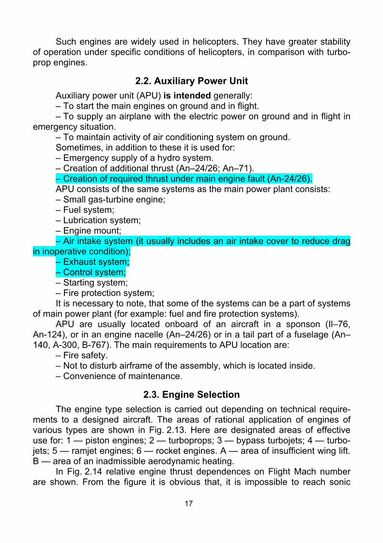
by Horizontal Packet 3. (By–pass) turbojets in nacelles under a lifting body (Fig. 2.29). [+] The air intake ducts are short and straight. Hence pressure losses in
them are small. [+] When one engine is failed, the second usually remains operational. [+] It is possible to control direction by difference of thrusts of engines. [+] The access at maintenance on ground is convenient. [+] The body is free to arrange some equipment. [–] When one engine is failed, the turning moment is more, than at the
previous schemes. [–] It is possible to ingest some foreign matter from ground. Such arrangement is applied on F-14, MiG-29, Su-27 fighters, Su-34
bomber.
27
Fig. 2.29. Arrangement of (By–pass) Turbojets in Nacelles under
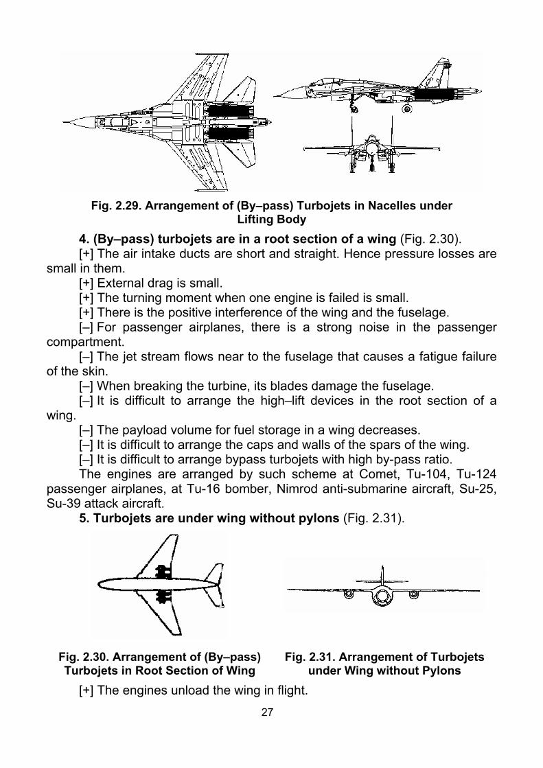
Lifting Body 4. (By–pass) turbojets are in a root section of a wing (Fig. 2.30). [+] The air intake ducts are short and straight. Hence pressure losses are
small in them. [+] External drag is small. [+] The turning moment when one engine is failed is small. [+] There is the positive interference of the wing and the fuselage. [–] For passenger airplanes, there is a strong noise in the passenger
compartment. [–] The jet stream flows near to the fuselage that causes a fatigue failure
of the skin. [–] When breaking the turbine, its blades damage the fuselage. [–] It is difficult to arrange the high–lift devices in the root section of a
wing. [–] The payload volume for fuel storage in a wing decreases. [–] It is difficult to arrange the caps and walls of the spars of the wing. [–] It is difficult to arrange bypass turbojets with high by-pass ratio. The engines are arranged by such scheme at Comet, Tu-104, Tu-124
passenger airplanes, at Tu-16 bomber, Nimrod anti-submarine aircraft, Su-25, Su-39 attack aircraft.
5. Turbojets are under wing without pylons (Fig. 2.31).
Fig. 2.30. Arrangement of (By–pass) Turbojets in Root Section of Wing
Fig. 2.31. Arrangement of Turbojets under Wing without Pylons
[+] The engines unload the wing in flight.

28
[+] The main landing gear can be retracted in an engine nacelle, thus total drag of an airplane is decreased.
[+] The engines are mounted directly to a wing without a pylon. Thus the mass of engine mount decreases.
[–] The interference of the wing and the engine nacelle results in reduc-tion of the critical Mach number. Therefore such scheme is not applied on tran-sonic and supersonic airplanes.
[–] The turning moment when one engine is failed is more, than in the previous schemes.
Yak-25, Yak-28 fighters, Il-28, Il-46 bombers were built by such scheme. 6. (By–pass) turbojets are in a tail part of a fuselage with pylons
(Fig. 2.32). [+] The wing is aerodynamically clean. [+] The noise in the cabin is small. [+] The turning moment, when one engine is failed, is small. [+] There is a good access to engine at maintenance. [+] The wing shields engines from ingestion of foreign matter from
ground. [+] It is simple to arrange the devices of thrust reverse. [–] Engines do not unload the wing; hence, the wing mass increases. [–] Engines load the tail part of the fuselage, hence, the fuselage mass
increases. [–] Fuel pipelines pass thought the fuselage; thus fire danger increases. [–] It is difficult to center–of–gravity of an empty airplane. Sometimes the
fourth landing gear strut in tail part is required (Il-62). [–] The extended nose part impairs performance of longitudinal and direc-
tional stability of an airplane. Now the most of passenger low-wing monoplanes for small number of
passengers (executive airplane) with (bypass) turbojets is designed by such scheme. In past, some mid passenger airplanes (Caravel, Tu-134, B-727) were built by such scheme. The A-10 attack aircraft is built by such scheme too.
7. (Bypass) turbojets are under the wing with pylons (Fig. 2.33).
Fig. 2.32. Arrangement of Turbojets in Tail Part of Fuselage with Pylons
Fig. 2.33. Arrangement of (Bypass) Turbojets under Wing with Pylons
[+] The engines unload a wing in flight.
29
[+] The engines serve as anti-flutter mass. [+] If a height above ground is small, than access for engine maintenance
is good. [+] There is low fire danger. [+] It is simple to arrange the device of thrust reverse. [–] The turning moment, when one engine is failed, is big. [–] For low-wing monoplanes, it is possible to ingest foreign matter into
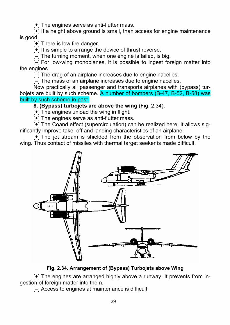
the engines. [–] The drag of an airplane increases due to engine nacelles. [–] The mass of an airplane increases due to engine nacelles. Now practically all passenger and transports airplanes with (bypass) tur-
bojets are built by such scheme. A number of bombers (B-47, B-52, B-58) was built by such scheme in past.
8. (Bypass) turbojets are above the wing (Fig. 2.34). [+] The engines unload the wing in flight. [+] The engines serve as anti-flutter mass. [+] The Coand effect (supercirculation) can be realized here. It allows sig-
nificantly improve take–off and landing characteristics of an airplane. [+] The jet stream is shielded from the observation from below by the
wing. Thus contact of missiles with thermal target seeker is made difficult.
Fig. 2.34. Arrangement of (Bypass) Turbojets above Wing
[+] The engines are arranged highly above a runway. It prevents from in-gestion of foreign matter into them.
[–] Access to engines at maintenance is difficult.

30
[–] The turning moment when one engine is failed is big. [–] Significant negative pitching moment at engine operation and positive
one at their fault, require increase of horizontal tail area. [–] Because jet stream directly contacts with upper wing surface, that
high-temperature coating is required for it. The An-74 STOL airplane is serially built by such scheme.
2.5.5. Heavy supersonic airplanes At heavy supersonic airplanes the engines are usually arranged in na-
celles underneath the wing or a lifting body. There are three versions of their arrangement (Fig. 2.35).
1. All engines are in one packet (Fig. 2.35, a). [+] Effect from compression under a fuselage is the greatest. [+] Turning moment, when one engine is failed, is the smallest. [–] Air intake is long; hence the pressure losses are big. [–] Wing is not unloaded, hence, the mass of the wing increases. The majority of heavy supersonic aircraft (Tu-144 experimental, T-4, XB-
70) had been built and designed by such scheme.
a b c
Fig. 2.35. Versions of Arrangement of Engines at Heavy Supersonic Airplanes
2. The engines are in packets by pairs (Fig. 2.35, b). [+] Fire danger is smaller. [+] Length of the air intakes is smaller. [–] Positive effect from compression is less. [–] Turning moment is more. Both supersonic airliners Tu-144 and Concord were serially built by such
scheme. 3. The engines are in personal nacelles (Fig. 2.35, c). [+] Fire danger is minimal. [+] Length of air intakes is minimal. [+] Engines unload the wing in flight. Hence the wing has smaller weight. [–] Turning moment, when one engine is failed, is the biggest. [–] Positive effect from compression is minimal.
Checklist 1. How can aircraft power plants be classified? 2. Why is the number of radial engines cylinders usually odd?

31
3. What is the reason of appearance of two- and four-row radial en-gines?
4. How to classify in-line piston engines by cylinder blocks arrangement on the front view?
5. List advantages, disadvantages and areas of application for aviation piston engines.
6. Why an aircraft, equipped only by piston engines, cannot reach sonic speed in horizontal flight?
7. List advantages, disadvantages and areas of application for turboprop engines.
8. What are the differences between turboprop and turboshaft engines? 9. List main units of turboprop engine. 10. What is the principal feature of prop-fan engine? 11. What are the differences between turbojet and bypass turbojet en-
gines? 12. List advantages, disadvantages and areas of application for bypass
turbojet engines. 13. List advantages, disadvantages and areas of application for bypass
turbojet engines with afterburner. 14. List advantages, disadvantages and areas of application for ramjet
engines. 15. What types of rocket engines do you know? 16. List advantages, disadvantages and areas of application for liquid-
propellant rocket engines. 17. List advantages, disadvantages and areas of application for solid-
propellant rocket engines. 18. What kinds of engines are called combined? 19. What is combined power plant? 20. What is APU intended for? 21. What are the systems APU consists of? 22. Where usually is APU located? Why? 23. What is the base for rational engine model selection? 24. What are altitude-airspeed performances of engines? 25. What is the base for rational engine number selection? 26. List advantages, disadvantages and areas of application for arrange-
ment of piston engine in nose part of fuselage. 27. List advantages, disadvantages and areas of application for arrange-
ment of piston engine in mean part of fuselage. 28. List advantages, disadvantages and areas of application for arrange-
ment of piston engine with a pusher propeller in tail part of fuselage. 29. List advantages, disadvantages and areas of application for arrange-
ment of piston engine with tractor propellers on wing. 30. List advantages, disadvantages and areas of application for arrange-
ment of piston engine with pusher propellers on wing.

32
31. List advantages, disadvantages and areas of application for arrange-ment of turboprop engine under wing.
32. List advantages, disadvantages and areas of application for arrange-ment of turboprop above wing.
33. List advantages, disadvantages and areas of application for arrange-ment of (bypass) turbojet engines in fuselage with nose air intake.
34. List advantages, disadvantages and areas of application for arrange-ment of (bypass) turbojet engines in fuselage with air intake located under nose part of fuselage.
35. List advantages, disadvantages and areas of application for arrange-ment of (bypass) turbojet engines in fuselage by vertical packet.
36. List advantages, disadvantages and areas of application for arrange-ment of (bypass) turbojet engines in fuselage by horizontal packet.
37. List advantages, disadvantages and areas of application for arrange-ment of (bypass) turbojet engines in nacelles under lifting body.
38. List advantages, disadvantages and areas of application for arrange-ment of (bypass) turbojet engines in root section of wing.
39. List advantages, disadvantages and areas of application for arrange-ment of (bypass) turbojets in tail part of fuselage with pylons.
40. List advantages, disadvantages and areas of application for arrange-ment of (bypass) turbojets under wing with pylons.
41. List advantages, disadvantages and areas of application for arrange-ment of (bypass) turbojet engines above wing.
42. List advantages, disadvantages and areas of application for different arrangement of (bypass) turbojet engines on heavy supersonic airplanes.

33
Theme 3. NACELLES AND COWLINGS OF ENGINES. ENGINE MOUNT
3.1. Nacelles and Cowlings of Engines
3.1.1. Purpose and Components of Nacelles and Cowlings The nacelle is intended to reduce aerodynamic drag and to organize air-
flow ensuring cooling of engine. Requirements to engine nacelles are: – Minimal aerodynamic drag in a system of the aircraft (at working engine
or inoperative one; in view of an aerodynamic interference). – Rational organization of airflow for cooling an engine (propeller gear,
cooler installations). – Good access to power plant at maintenance on ground. – Provision of fire safety (firewalls for fire isolation). The nacelle usually consists of a body and cowlings. Airframe of cowlings
can be frame and panel. In the frame schemes, strength and stiffness are formed by a framework.
Removable covers with thin skin, reinforced by load–carrying structure, are mounted to this framework. Such structure works well at low flight speeds (up to 400350... km/h). In addition, with using of bypass turbojets with high bypass ratio, two new factors appear: the first is high intensity vibroacoustic vibration (leading to cracks and crashes of classic frame structures) and the second is powerful fan noise (which cannot be absorbed by frame structures).
The solution of this problem is application of sandwich fiberglass plastic panel structures. Although they are more expensive in manufacturing, they pro-vide significantly lower mass at the same strength, better absorb vibration and have a lot of specific properties. Exactly such structures begin to be the main ones for flight speeds above 400 km/h. The panel cowling consists of stiff pan-els connected to each other by locks and forming the closed load–carrying shell.
Loads from a cowling are transmitted to an engine, and through engine mount to an aircraft. Simultaneous attachment of the cowling to the engine and to the aircraft is prohibited. Stiff covers of panels are made not removable, but hinging — with attachment fittings. In an open position, special braces support the cover. For the best fit of the covers in the closed position there are pres-sure–sealing parts on joints of panels.
3.1.2. Airframe of Nacelles for Various Types of Engines Nacelle of piston engines (Fig. 3.1) consists of spinner, cowling and
casing. The cowling is mounted to engine and consists of air intake and hinging parts. Load-carrying elements in the casing of the nacelle carry loadings from engine mount and transmit them to an aircraft.
34
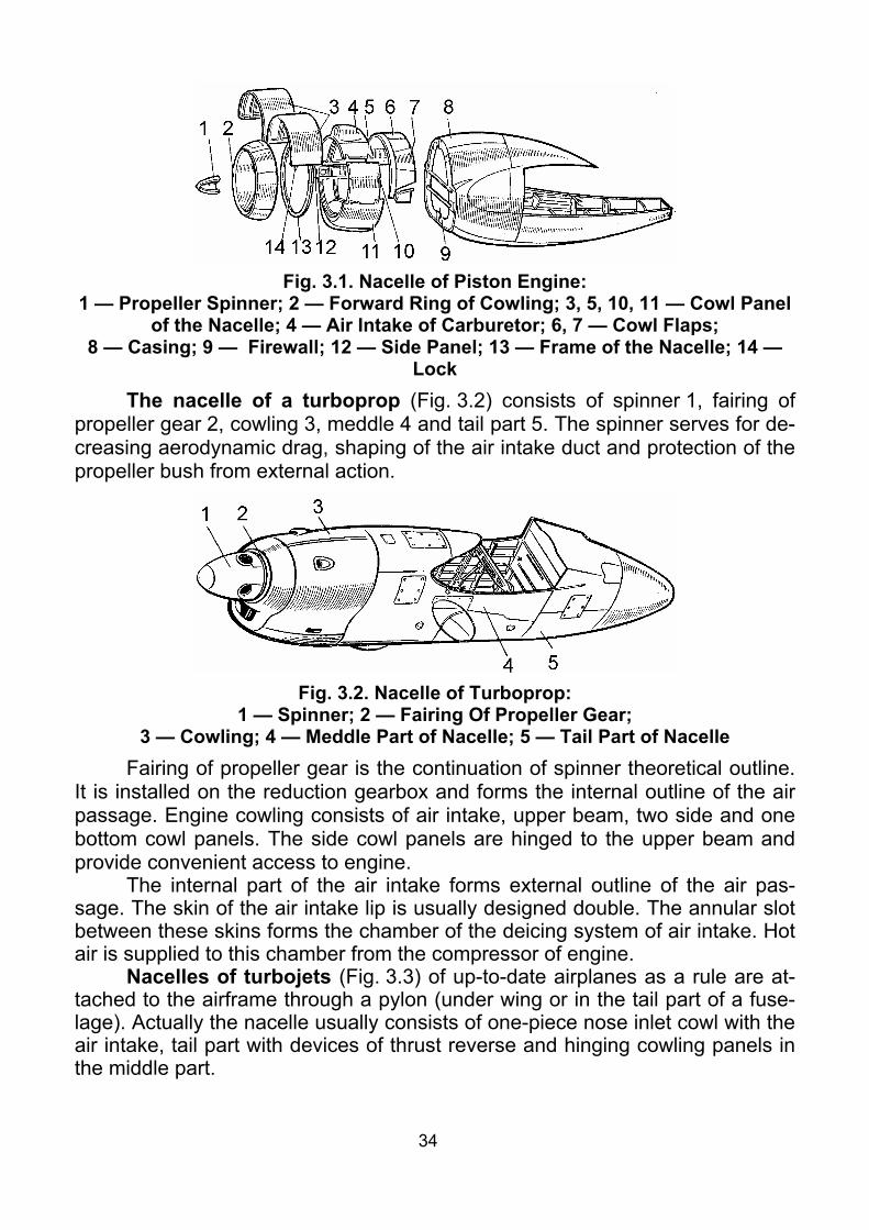
Fig. 3.1. Nacelle of Piston Engine:
1 — Propeller Spinner; 2 — Forward Ring of Cowling; 3, 5, 10, 11 — Cowl Panel of the Nacelle; 4 — Air Intake of Carburetor; 6, 7 — Cowl Flaps;
8 — Casing; 9 — Firewall; 12 — Side Panel; 13 — Frame of the Nacelle; 14 — Lock
The nacelle of a turboprop (Fig. 3.2) consists of spinner 1, fairing of propeller gear 2, cowling 3, meddle 4 and tail part 5. The spinner serves for de-creasing aerodynamic drag, shaping of the air intake duct and protection of the propeller bush from external action.
Fig. 3.2. Nacelle of Turboprop:
1 — Spinner; 2 — Fairing Of Propeller Gear; 3 — Cowling; 4 — Meddle Part of Nacelle; 5 — Tail Part of Nacelle
Fairing of propeller gear is the continuation of spinner theoretical outline. It is installed on the reduction gearbox and forms the internal outline of the air passage. Engine cowling consists of air intake, upper beam, two side and one bottom cowl panels. The side cowl panels are hinged to the upper beam and provide convenient access to engine.
The internal part of the air intake forms external outline of the air pas-sage. The skin of the air intake lip is usually designed double. The annular slot between these skins forms the chamber of the deicing system of air intake. Hot air is supplied to this chamber from the compressor of engine.
Nacelles of turbojets (Fig. 3.3) of up-to-date airplanes as a rule are at-tached to the airframe through a pylon (under wing or in the tail part of a fuse-lage). Actually the nacelle usually consists of one-piece nose inlet cowl with the air intake, tail part with devices of thrust reverse and hinging cowling panels in the middle part.

35
3.2. Engine Mount
3.2.1. Engine Mount. General The engine mount is intended to
attach an engine with the units and equipment installed on it to attachment fittings of an airframe.
From the point of view of structural mechanics engine mount are subdivided into truss, beam, truss-girder and frame. We should note that, in many cases truss engine mount are very original. For ex-ample (bypass) turbojets are frequently attached to airframe by separate rods.
Such system provides geometrical stability only as a whole. Engine mount are usually designed as statically indeterminate systems. It
promotes reliability and survivability of engine mount. However rigging of en-gine mount becomes complicated. After consummation of aviation regulation FAR-25, a new concept fail-safe structure is appeared. It means, that structure must perform its functions at any one its element fails.
It is necessary to keep in mind that engine is attached to engine mount by brackets or trunnions. They are arranged on the engine in the strongest and the stiffest places.
(Bypass) turbojets and turboprops are usually attached to engine mount at two (seldom at three) supporting locations. Afterburners and extension pipes are movably attached by the additional supporting locations.
When designing the engine mount, it is necessary to provide access to units of the engine (and to the equipment installed on it) for maintenance. It is also required to provide a fast engine replacement.
Requirements to engine mount are the following. 1. Carry all loadings from engine with the units and the equipment in-
stalled on it under any allowable operation conditions. Thus casing of the en-gine must not include in airframe of aircraft.
2. Provide specified strength and stiffness at minimal mass. 3. Absorb the vibration from engine and propeller that they were not
transmitted to an airframe of aircraft. 4. Compensate for temperature deformations of engine parts without any
additional load in these parts and in aircraft airframe. 5. Maintain high survivability and specified service life. 6. Aerodynamic drag should be minimal. 7. Maintainability (little duration of installation and removal of engine;
ease of rigging; good access at maintenance.)
Fig. 3.3. Nacelle of Turbojet

36
3.2.2. Loadings Let's consider loadings which load engine mount while in service. They
are mass and aerodynamic forces, thrust force, reaction torque from a propel-ler, loadings from a device of thrust reverse. Moreover in case of changing of aircraft motion direction, gyroscopic moment loads the engine mount.
The mass forces are calculated by power plant mass. The power plant mass includes: mass of engine and mass of all equipment, cowlings, propellers and other units attached to the engine.
Approximately power plant mass can be determined as follows: for airplanes with (bypass) turbojets ( ) enPP m6121m ...... = ; for airplanes with turboprops ( ) enPP m2291m ...... = ,
where enm — mass of the engine. The gyroscopic moment is determined by formula
( )ixixxG JM ωωωω= ,sin , where xJ — mass moment of inertia of rotated parts of the engine, kg⋅m2;
xω — angular velocity of rotated parts of the engine, s-1; iω — angular velocity of rotation of the aircraft around of the i axis, s-1. For turboprops, by-pass tur-bojets and geared piston engines, the adduced moment of inertia and adduced angular velocity of rotating parts of the engine are used.
The gyroscopic moment is directed in such a way that the axis of rotating parts of the engine should be turned to the i axis in the shortest way.
The reaction torque from a propeller of piston engine or turboprop acts in the direction opposite to rotation of a propeller and is equal to, N⋅m:
pp
p n2N60NM⋅π
=ω
= ,
where N — shaft power of a propeller, W; pω — angular velocity of rotation of a propeller, s-1; pn — number of revolutions of propeller per minute. In case of installation of coaxial contra-rotating propellers their reaction torques are sub-tracted. Taking into account nonuniformity of power distribution between pro-pellers, it is usually assumed:
( )p
p n2N602010M⋅π
= ..... .
Thrust force of piston engines or turboprops is determined by for-mula, N:
H
pe
VN
Tη
= ,
where eN — effective power of the engine, W; вη — efficiency of the propeller; HV — flight speed, m/s.
Efficiency of the propeller depends on the flight speed in a complicated manner. Therefore within the course project, it is possible to use the approxi-

37
mate relation for take off thrust: ( ) eN420417T .....≈ .
The aerodynamic forces, acting to a cowling of engine, are determined by wind-tunnel tests.
The mass forces are applied in a center of mass of engine. These mass forces are gravity force and inertial forces. These inertial forces appear in case of changes of flight direction and aircraft attitude. At strength analysis, they usually use the coordinate system fixed in aircraft (the body axes). Origin of this coordinate system is fixed to center of mass of aircraft. The x0 axis is directed forward along the axis of the aircraft. The y0 axis lies in a plane of symmetry of aircraft perpendicularly to x0 . The z0 axis is directed by right-hand triple (as a vector product of units of x0 and y0 axes).
3.2.3. Critical Load Conditions Forces and moments loading to engine mount in run of aircraft, can as-
sume various values. Therefore there are normative papers, such as NLGS-3, AP, FAR, JAR. A number of positions of aircraft, corresponding to the heaviest loading conditions are specified in them. These cases are called critical load conditions. Selection of the normative paper is determined by the technical requirements to the designed aircraft.
These critical load conditions are studied in detail in the course «Strength analyses of aircraft». Here, we will consider only supplementary conditions for engine mount according to AP-25.
«Engine and APU torque. (a) Each engine mount, APU and its supporting structure must be de-
signed for the effects of (1) A limit engine or APU torque corresponding to takeoff power and
propeller speed, acting simultaneously with 75 percent of the limit loads from flight condition 1;
(2) A limit torque corresponding to the maximum continuous power and propeller speed, acting simultaneously with the limit loads from flight condi-tion 1;
(3) For turboprop installations, in addition, a limit engine torque corre-sponding to takeoff power and propeller speed, multiplied by a factor account-ing for propeller control system malfunction, including quick feathering, acting simultaneously with 1g level flight loads. In the absence of a rational analysis, a factor of 1.6 must be used.
(b) For turbine engine and APU installations, the engine mount and sup-porting structure must be designed to withstand each of the following:
(1) A limit engine torque load (considering as limit), imposed by: (i) sudden engine or APU stoppage due to malfunction, which can be
a temporary loss of power or thrust and which can cause stoppage as a result of vibrations;

38
(ii) limit angular acceleration of engine or APU. (2) A limit engine torque load (considering as ultimate), imposed by
stoppage of engine or APU due to structural failure (such as compressor jam-ming).
(c) This limit engine torque must be obtained by multiplying mean torque for the specified power and speed by a factor of:
(1) 1.25 for turboprop installations; (2) 1.33 for piston engines with five or more cylinders; (3) 2, 3, or 4, for engines with four, three, or two cylinders, respectively. (A) Appling (a) to turbojets, limit torque must be equal to the torque ap-
pearing at limit angular acceleration of engine rotating parts. Side load on engine mount. (a) Each engine mount and its supporting structure must be designed for
a limit load factor in a lateral direction, for the side load on the engine mount, at least equal to the maximum load factor obtained in the yawing conditions but not less than 1.33.
(b) This side load may be assumed to be independent of other flight con-ditions.
(A) When engine is mounted to a wing, side load directed from axis of airplane must be not less than PP
2xz mrP .⋅ω= ,
where PPm . — power plant mass; xω — limit roll angular velocity; r — distance from engine center of gravity to longitudinal axis of airplane in plane view.
(B) Simultaneous action of above specified side load and weight of en-gine must be considered too.»
Critical condition 1 corresponds to curved flight with limit lift coefficient and limit load factor.
3.3. Airframes of Engine Mount
3.3.1. Engine Mounts for Radial Piston Engines Radial piston engine is usually attached by frame (Fig. 3.4). This frame
consists of 8–10 beams and a load-carrying ring 1 with attachment fittings 4 for the engine. Shock absorbers are installed in these fittings. In addition the other shock absorbers can be installed in attachment fittings to the airplane. Gusset plates 3 are usually used to reinforce welding places. As each beam takes six degrees of freedom, exactly such system is forty two times statically indetermi-nate (8 × 6 – 6 = 42).
In designing calculations, for simplification, this frame is considered as a truss. That is the beams with anchorage at their ends are considered as rods with hinges at thier ends. It turns the mathematical model to twice statically in-determinate (8 – 6 = 2).

39
Fig. 3.4. Frame Engine Mount of Radial Piston Engine:
1 — Load-Carrying Ring; 2 — Beams; 3 — Gusset Plates; 4 — Engine-to-Engine Mount Attachment Fitting; 5 — Engine Mount-to-Airframe Attachment Fitting
In other cases, engine can be attached by truss. So truss engine mount for radial piston engine is shown in Fig. 3.5. It consists of load-carrying ring 1, carrying engine attachment fittings (Ref. cross-section A-A) with shock absorb-ers. And rods 2, 12 of truss hinged to the ring and welded between each other with gusset plates. Forks 3 are welded into the rods in truss-to-airframe at-tachment fittings. Assuming forks 3 as a hinge connection, we obtain that this system is twice statically indeterminate.
The engine mount of piston engine is usually made of high-strength al-loyed steels. To provide the fatigue life, they use the moderated hardening ( 12001100b ...=σ [MPa]).
Rigging of such system is carried out in attachment fittings to the air-frame. Temperature deformations are compensated by shock absorbers. Strength analysis is performed by known methods of structural mechanics.
In practice, multispan engine mount are met (Fig. 3.6). This is due to the fact that engines are usually used as anti-flatter mass. For this purpose they are moved forward relatively to wing leading edge. In the same time, for mini-mization of the aerodynamic drag, optimality of angles of the truss
( )°≈α 4530... and rod’s length decreasing (which leads to its global crippling stresses in-crease), it is expedient to have two spans of the truss. Double-span engine mount espe-cially widely used for turboprops (ref. sub-paragraph 3.3.3).
Fig. 3.6. Scheme of Double–span Engine Mounts

40
Fig. 3.5. Truss Engine Mount of Radial Piston Engine for Light Airplane:
1 — Load-Carrying Ring; 2 — Upper Rods; 3 — Fork; 4 — Nut; 5 — Pin; 6 — Washer; 7 — Bush Shock Absorbers; 8 — Washer; 9 — Box; 10 — Shock Ab-
sorber Casing; 11 — Brackets; 12 — Bottom Rods
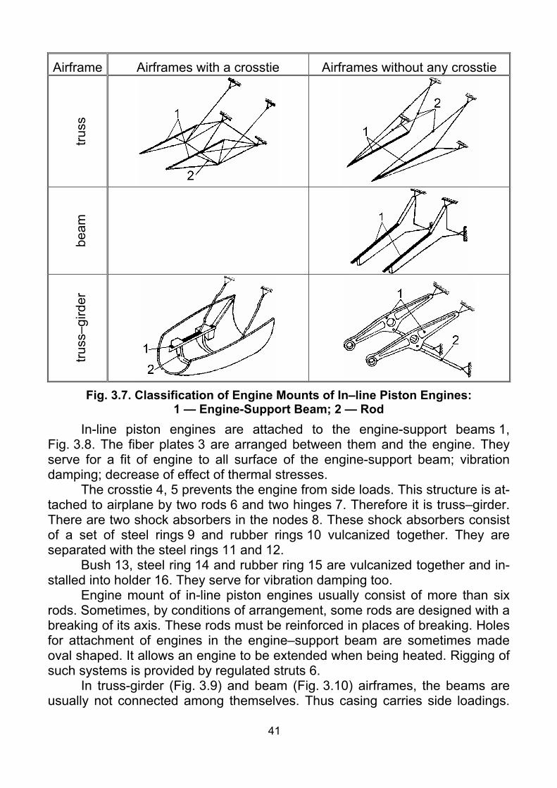
3.3.2. Engine Mounts of In-Line Piston Engines Engine mounts of in-line piston engines (Fig. 3.7) are classified ac-
cording to: 1) Airframe: truss, truss-girder, beam and frame; 2) Transmission of side loading: with a crosstie (the casing of engine
does not transmit any side loading) and without a crosstie (the casing of engine transmits side loading);
3) Type of attachment: concentrated attachment and distributed attachment.
41
Airframe Airframes with a crosstie Airframes without any crosstie tru
ss
beam
truss
–gird
er
Fig. 3.7. Classification of Engine Mounts of In–line Piston Engines:
1 — Engine-Support Beam; 2 — Rod In-line piston engines are attached to the engine-support beams 1,
Fig. 3.8. The fiber plates 3 are arranged between them and the engine. They serve for a fit of engine to all surface of the engine-support beam; vibration damping; decrease of effect of thermal stresses.
The crosstie 4, 5 prevents the engine from side loads. This structure is at-tached to airplane by two rods 6 and two hinges 7. Therefore it is truss–girder. There are two shock absorbers in the nodes 8. These shock absorbers consist of a set of steel rings 9 and rubber rings 10 vulcanized together. They are separated with the steel rings 11 and 12.
Bush 13, steel ring 14 and rubber ring 15 are vulcanized together and in-stalled into holder 16. They serve for vibration damping too.
Engine mount of in-line piston engines usually consist of more than six rods. Sometimes, by conditions of arrangement, some rods are designed with a breaking of its axis. These rods must be reinforced in places of breaking. Holes for attachment of engines in the engine–support beam are sometimes made oval shaped. It allows an engine to be extended when being heated. Rigging of such systems is provided by regulated struts 6.
In truss-girder (Fig. 3.9) and beam (Fig. 3.10) airframes, the beams are usually not connected among themselves. Thus casing carries side loadings.
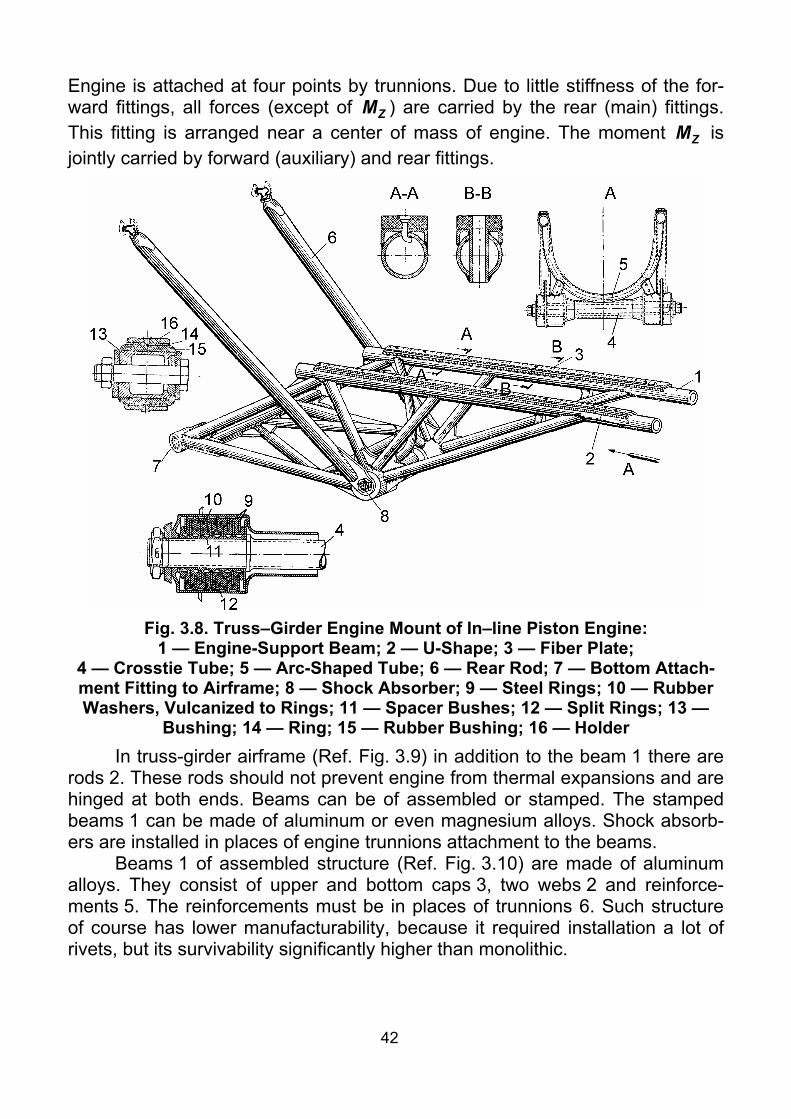
42
Engine is attached at four points by trunnions. Due to little stiffness of the for-ward fittings, all forces (except of ZM ) are carried by the rear (main) fittings. This fitting is arranged near a center of mass of engine. The moment ZM is jointly carried by forward (auxiliary) and rear fittings.
Fig. 3.8. Truss–Girder Engine Mount of In–line Piston Engine:
1 — Engine-Support Beam; 2 — U-Shape; 3 — Fiber Plate; 4 — Crosstie Tube; 5 — Arc-Shaped Tube; 6 — Rear Rod; 7 — Bottom Attach-ment Fitting to Airframe; 8 — Shock Absorber; 9 — Steel Rings; 10 — Rubber Washers, Vulcanized to Rings; 11 — Spacer Bushes; 12 — Split Rings; 13 —
Bushing; 14 — Ring; 15 — Rubber Bushing; 16 — Holder In truss-girder airframe (Ref. Fig. 3.9) in addition to the beam 1 there are
rods 2. These rods should not prevent engine from thermal expansions and are hinged at both ends. Beams can be of assembled or stamped. The stamped beams 1 can be made of aluminum or even magnesium alloys. Shock absorb-ers are installed in places of engine trunnions attachment to the beams.
Beams 1 of assembled structure (Ref. Fig. 3.10) are made of aluminum alloys. They consist of upper and bottom caps 3, two webs 2 and reinforce-ments 5. The reinforcements must be in places of trunnions 6. Such structure of course has lower manufacturability, because it required installation a lot of rivets, but its survivability significantly higher than monolithic.

43
Fig. 3.9. Truss-Girder Engine Mount of In–Line Piston Engine:
1 — Beam; 2 — Rod; 3 — Hinged Attachment Fitting; 4 — Forward Trunnion; 5 — Rear Trunnion; 6 — Forward Trunnion Shock Absorber
Fig. 3.10. Beam Engine Mount of In–Line Piston Engine:
1 — Engine-Support Beam; 2 — Web; 3 — Cap; 4 — Attachment Fitting to Air-frame; 5 — Reinforcing Bracket; 6 — Trunnion
3.3.3. Truss Engine Mounts of Turboprops Engine mounts of turboprops can be classified by the following features:
by airframe type — truss and truss-girder (Fig. 3.11); by number of engine at-

44
tachment points — three-point, four-point and multipoint; by number of spans — single-span and double-span. The last is often called engine mount with transitional truss.
As stated above, to increase critical flutter speed, engines are usually moved forward relatively to wing. In case of truss airframe application, as a rule, it leads to double-span engine mount creation. Otherwise decreased an-gles between rods lead to significant increase of internal loading in truss ele-ments, and therefore, to mass increase. In place of truss spans jointing, load-carrying frame is usually installed. So, rod’s length decreases approximately twice, that leads to approximately fourfold increase of global crippling stresses and mass decrease.
It is necessary to note, that all engine mount elements should be con-nected so, that their axes are intersected at elements ends. This eliminates general bending. But sometimes, small local bending stresses can appear in compliance with arrangement conditions.
Truss airframe Truss-girder airframe
Thre
e-po
int
Four
-poi
nt
Mul
tipoi
nt
Fig. 3.11. Engine Mounts of Turboprops Classification
The span of truss, which elements are directly attached to engine, we shall call engine mount proper; the second span of truss, we shall call transi-tional truss.

45
Let us consider a number of examples for truss engine mounts. Truss engine mount of turboprop under wing shown in Fig. 3.12 con-
sists of engine mount proper, frame and transitional truss. Engine attachment points are two side trunnions (A) in forward supporting
location and two side trunnions (B) in rear supporting location. In this case there is four-point engine attachment. Such attachment type significantly simpli-fies engine rigging. So forward attachment fittings are made unassembled.
Forward supporting location consists of six rods (1, 1’, 2, 2’, 3, 3’) and two shock absorbers, which are located inside ends of rods 2 and 2’. Rods 1, 1’, 3, 3’ are attached to ends of rods 2, 2’ (shock absorber casings) through hinged bearings so, that their axes are intersected in one point lying on forward trun-nion axis. This eliminates rods bending without considerable structure compli-cation. On the other hand, rods of forward supporting location are attached to transitional truss through brackets on frame 5 of engine nacelle.
Fig. 3.12. Truss Engine Mount of Turboprop of Passenger Airplane
(Four-Point Attachment): 1 — Bottom Rod; 2, 2’ — Upper Rods; 3, 3’ — Mean Rods;
4, 4’ — Rear Rods-Shock Absorbers; 5 — Frame; 6, 7, 8, 9 — Rods of Transitional Truss; 10 — Brackets on Forward Wing Spar
Rear supporting location consists of two trunnions and two vertical rods-shock absorbers 4, 4’, which are attached to the same brackets on the frame, as rods 2, 2’ of forward supporting location.
Transitional truss consists of eight non-adjustable rods 6, 7, 8, 9 and at-taches engine mount proper to brackets 10 on the forward wing spar in places of two load-carrying ribs installation. Load-carrying frame 5 is reinforced with duralumin angle plank among brackets for rods 1 and 2, 2 and 2’, 2’ and 1’. It allows to remove engine with cowls and units installed on it together with en-gine mount proper.

46
Engine mount proper consists of eight rods (six in forward supporting lo-cation and two in rear one) and is twice statically indeterminate (8 – 6 = 2). Transitional truss is also twice statically indeterminate. Static indeterminacy in-creases engine mount survivability, as in case of any rod or two non-symmetrical rods failure, system keeps stable. But in this case, engine rigging is complicated, because initially it is required to disconnect two redundant ele-ments (and such, disconnection of which does not turn the engine mount to mechanism), then to make rigging and connect redundant elements again.
Let us consider this engine mount operation under loading. Using symme-try and considering symmetrical and anti-symmetrical loads separately, the problem can be reduced to once statically indeterminate. (Under the action of symmetrical loads, internal forces in symmetrical rods are equal, and under the action of anti-symmetrical loads, internal forces in symmetrical rods are equal by absolute value and have opposite sign.)
Forward supporting location carries out loading from engine thrust, lateral loading and a part of reaction torque from a propeller and vertical mass loading. Rear supporting location carries out the rest part of reaction torque from a pro-peller and vertical mass loading.
In the first approximation, vertical loading can be distributed inversely proportional to distances from center-of-gravity to supporting locations. Then, considering nodes A and B equilibrium, it is possible to see, that external load-ings are carried out in the following manner:
xF A 1, 1’, 2, 2’, 3, 3’ xM А+B 1, 1’, 2, 2’, 4, 4’ yF А+B 1, 1’, 2, 2’, 3, 3’, 4, 4’ yM A 1, 1’, 2, 2’, 3, 3’
zF A 1, 1’, 2, 2’, 3, 3’ zM А+B 1, 1’, 2, 2’, 3, 3’, 4, 4’
All rods are made of high-strength alloyed steel. Rods of engine mount proper (excepting 2 and 2’) are provided with transitional bushings and adjust-able rod ends from one side. Transitional bushings are connected to rods by right-hand thread, and to rod ends by left-hand thread. It allows staples rigging of engine mount. Check-holes in threaded parts and in transitional bushings serve to check the minimal required number of thread turns, providing carrying-out of ultimate loads. After finishing rigging, all thread connections are locked with locking nuts and locking wire.
Electrical jumpers, connecting engine with ends of rods 2, 2’ (shock ab-sorber casings) and transitional truss with brackets on the forward spar, serve to eliminate potential difference between engine and engine mount, and also between engine mount and airframe of airplane.
It is necessary to note, that this engine mount, having designed in the be-ginning of 50-th of last century for An-10/12 airplanes, then has been applied practically without any changes on An-24/26/30 airplanes (which total amount was more than three thousand), and so was time tested. And nowadays, it was applied with minimal changes during designing of modern An-140 airplane.

47
Fig. 3.13 shows truss engine mount of turboprop of passenger air-plane. Here, engine with gearbox is attached to wing by double-span truss, frame and rear supporting location.
Fig. 3.13. Truss Engine Mount of Turboprop of Passenger Airplane
(Three-Point Attachment with Reserve Elements): 1 — Bottom Rods; 2 — Upper Rods; 3 — Rear Rods; 4 — Central Bracket;
5 — Rear Rods; 6 — Reserve Rods; 7, 8, 9, 10 — Rods of Transitional Truss; 11 — Tail Rods; 12 — Brackets; 13 — Frame; 14 — Arc Brackets; 15 — Forward
Trunnion; 16 — Clamps Engine attachment fittings are two side trunnions 15 of forward gearbox
and one center trunnion of rear gearbox. Such attachment is usually called three-point attachment. Its significant disadvantages, strangely enough, are dif-ficulties of engine rigging and, as a result, mounting stresses appear possibility in case of wrong assembling. It leads to special stand creation necessity for exact engine installation onto engine mount, that is possible in plant conditions only. Such way is not suitable for quick engine replacement. One of the solu-tions of this problem is complete prohibition for engine mount rods disassem-bling in maintenance. So engine replacement is carried out without rods disas-sembling, by removing clamps 1 in forward attachment fittings.
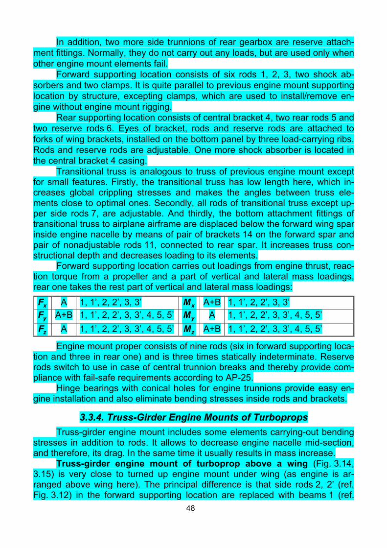
48
In addition, two more side trunnions of rear gearbox are reserve attach-ment fittings. Normally, they do not carry out any loads, but are used only when other engine mount elements fail.
Forward supporting location consists of six rods 1, 2, 3, two shock ab-sorbers and two clamps. It is quite parallel to previous engine mount supporting location by structure, excepting clamps, which are used to install/remove en-gine without engine mount rigging.
Rear supporting location consists of central bracket 4, two rear rods 5 and two reserve rods 6. Eyes of bracket, rods and reserve rods are attached to forks of wing brackets, installed on the bottom panel by three load-carrying ribs. Rods and reserve rods are adjustable. One more shock absorber is located in the central bracket 4 casing.
Transitional truss is analogous to truss of previous engine mount except for small features. Firstly, the transitional truss has low length here, which in-creases global crippling stresses and makes the angles between truss ele-ments close to optimal ones. Secondly, all rods of transitional truss except up-per side rods 7, are adjustable. And thirdly, the bottom attachment fittings of transitional truss to airplane airframe are displaced below the forward wing spar inside engine nacelle by means of pair of brackets 14 on the forward spar and pair of nonadjustable rods 11, connected to rear spar. It increases truss con-structional depth and decreases loading to its elements.
Forward supporting location carries out loadings from engine thrust, reac-tion torque from a propeller and a part of vertical and lateral mass loadings, rear one takes the rest part of vertical and lateral mass loadings:
xF A 1, 1’, 2, 2’, 3, 3’ xM А+B 1, 1’, 2, 2’, 3, 3’ yF А+B 1, 1’, 2, 2’, 3, 3’, 4, 5, 5’ yM A 1, 1’, 2, 2’, 3, 3’, 4, 5, 5’
zF A 1, 1’, 2, 2’, 3, 3’, 4, 5, 5’ zM А+B 1, 1’, 2, 2’, 3, 3’, 4, 5, 5’
Engine mount proper consists of nine rods (six in forward supporting loca-tion and three in rear one) and is three times statically indeterminate. Reserve rods switch to use in case of central trunnion breaks and thereby provide com-pliance with fail-safe requirements according to AP-25.
Hinge bearings with conical holes for engine trunnions provide easy en-gine installation and also eliminate bending stresses inside rods and brackets.
3.3.4. Truss-Girder Engine Mounts of Turboprops Truss-girder engine mount includes some elements carrying-out bending
stresses in addition to rods. It allows to decrease engine nacelle mid-section, and therefore, its drag. In the same time it usually results in mass increase.
Truss-girder engine mount of turboprop above a wing (Fig. 3.14, 3.15) is very close to turned up engine mount under wing (as engine is ar-ranged above wing here). The principal difference is that side rods 2, 2’ (ref. Fig. 3.12) in the forward supporting location are replaced with beams 1 (ref.

49
Fig. 3.14), and rods for lateral loading (3, 3’ in Fig. 3.12, 4 in Fig. 3.14), are at-tached to beams 1 near to their mid-section, that results in beams bending, but decreases the engine nacelle sizes. In addition, rod 4 length (in Fig. 3.14) comes shorter, than in truss airframe.
Fig. 3.14. Truss-Girder Engine Mount of Turboprop above Wing:
1 — Beam; 2 — Upper Rod; 3 — Rear Rod-Shock Absorber; 4 — Inner Rod; 5 — Load-Carrying Frame of Nacelle;
6, 8, 10 — Brackets; 7 — Link; 9, 13 — Electrical Jumpers; 11 — Forward Shock Absorber; 12 — Forward Engine Trunnion
It is necessary to note, that in this case the beams carry bending only from lateral loading, because hinge bearings are installed in beams 1-to-brackets 8 attachment fittings, and axes of the fittings lie in the same axis with rods 4 attachment fittings. So, under the action of vertical loading, beams 1 to-gether with rods 4 can freely rotate around common axis (passing through at-tachment fittings on the bracket 8). Beam 1 shape also decreases bending from thrust force. Beam part between engine trunnion and rod 4 attachment fitting operates practically as rod in view of very small angle between beam axis and engine axis in plane view. Beam part between rod 4 attachment fitting and bracket 8 also operates practically as rod. In the same time under the action of lateral load, element 1 is bent as beam on two supports with cantilever.
Rear supporting location is absolutely analogous to four-point truss en-gine mount and consists of two vertical adjustable rods-shock-absorbers, at-tached to rear engine trunnions in the bottom, and, in the up, with the same

50
brackets of engine nacelle frame to which upper rods 2 are attached. Loads carrying-out can be shown in the following view:
xF A 1, 2, 4 xM А+B 1, 2, 3 yF А+B 1, 2, 3 yM A 1, 2, 4
zF A 1, 2, 4 zM А+B 1, 2, 3
Fig. 3.15. Transitional Truss:
1 — Bottom Rod; 2 — Side Rod; 3, 4 — Central Rods; 5 — Upper Rod; 6, 8, 15, 17 — Brackets; 7, 11, 12 — Beams; 9 — Screen; 10 — Web;
13, 19, 20, 22 — Shapes; 14, 16 — Brackets; 18 — Forward Wing Spar; 21 — Engine Nacelle Skin
Transitional truss (See Fig. 3.15) in this case consists of nine rods and is three times statically indeterminable (9 – 6 = 3). Two upper adjustable rods (5 in

51
Fig. 3.15) together with load-carrying frame carry load from rods 2, 3 (ref. Fig. 3.14) of engine mount proper and transmit it to forward wing spar up-per cap. Two bottom rods 1 together with rods 2 (ref. Fig. 3.15) carry out load from beams 1 (ref. Fig. 3.14) and transmit it to the bottom and upper forward wing spar caps correspondingly. Three central rods 3, 4 (ref. Fig. 3.15) carry out lateral loading from rods 4 (ref. Fig. 3.14) and pass it to forward spar upper cap.
It is necessary to note, that all previous notes about materials used, elec-trical bonding and statically indeterminable engine mount rigging are applicable to all engine mounts, except apart defined cases.
Five-point engine mount of turboprop to fuselage is shown in Fig. 3.16. Engine attachment fittings are two forward trunnions, two rear side and one rear central brackets. Engine mount is a double-span structure. As en-gine is attached to fuselage and do not perform the anti-flutter mass function, that it could be attached without transitional truss. But in this case turboprop is installed instead of piston engine, and as mass of turboprop with the same power significantly less than mass of piston engine, such engine mount would lead to airplane center-of-gravity position change, which is inadmissible. It re-sults in so complicated transitional truss.
Fig. 3.16. Truss-Girder Engine Mount of Turboprop.
Five-Point Attachment to Fuselage

52
Forward engine supporting location practically corresponds to turned up previous engine mount. Forward engine trunnions are attached to shock ab-sorbers, connected to two beams 1 by means of clamps. These clamps are used for engine installation/removal, which eliminates engine mount rigging af-ter engine replacement. Beams 1 at the other end are hinged to arc 6. In addi-tion, two adjustable rods 4 are hinged to these beams near to their 1 middles. Bottom adjustable rods 2 are hinged below to the same shock absorbers. On the other side, bottom rods are also hinged to arc 6. Loads carrying-out can be shown in the following view:
xF A 1, 2, 4 xM А+В 1, 2, 3 yF А+B 1, 2, 3, 5 yM A 1, 2,
zF A 1, 2, 4 zM А+B 1, 2, 3, 5
Rear supporting location consists of two adjustable vertical rods 3 hinged at both ends and central link 5, connected to the arc through shock absorber.
Arc 6 is attached to transitional truss. Transitional truss consists of ten rods 7, 8, 9, 10, 11 and is four times (!) statically indeterminable. Four side nonadjustable rods 7, 10 are rigidly attached to arc 6 by one end, and hinged to fuselage load-carrying frame by the other end. Two upper 8, two bottom 11 and two side 9 adjustable rods are hinged to brackets of arc 6 by one end, and to fuselage frame by the other end.
Fig. 3.17 shows three-point truss-girder turboprop-to-wing engine mount of light passenger airplane. In this case, engine is attached to wing cen-ter section by means of truss, four brackets on forward wing spar, one bracket on rear spar and rear support. Rear support 6 is bolted to bottom panel of wing cen-ter section, which is reinforced here with beam. Engine attachment points are two side 10 and rear 7 trunnions. Each trunnion is attached to engine by four pins.
To decrease vibration, transmitted from engine to airframe through engine mount, two side shock absorbers 11 and one shock absorber of rear support are provided. They are equipped with disk-type rubber-metal shock absorbers.
Excepting rigid connection between upper rods 2 and forward shock ab-sorbers 11, all rods are attached to brackets or shock absorbers 2 by means of hinge bearings. Bottom rods 1 and side rod 3 from engine side are equipped with adjustable rod ends with transitional bushings, providing stepless change of their length.
Full thrust and reaction torque from propeller are carried out by forward supporting location. Vertical and lateral loadings, moments around vertical and lateral axes are jointly carried out by forward and rear supporting locations:
xF A 1, 2, 3 xM А 1, 2 yF А+B 1, 2, 3, 6 yM A+В 1, 2, 3, 6
zF A+В 1, 2, 3, 6 zM А+B 1, 2, 3, 6

53
Fig. 3.17. Three-Point Truss Turboprop-to-Wing Engine Mount of
Light Passenger Airplane 1 — Bottom Rods; 2 — Upper Rods; 3 — Side Rod; 4 — Rear Rods; 5 — Rear Bracket; 6 — Rear Support with Shock Absorber; 7 — Rear Trunnion; 8 — Up-per Bracket; 9 — Bottom Bracket; 10 — Side Trunnions; 11 — Forward Shock
Absorber All rods and trunnions are made of high-strength steel; bottom brackets 9
are made of titanium. Truss-girder engine mount of turboprop of light passenger airplane
with four-point attachment in single supporting location is shown in Fig. 3.18. In this case, engine attachment fittings are four brackets 2 in forward
supporting location and rod 14 of rear supporting location. Each bracket 2 is at-tached to mounting flanges on engine casing with four bolts. Bracket of rear supporting location is attached to engine casing with one bolt.
This engine mount consists of arc 3, four main rods 6, 5, 13, 8, four auxil-iary rods 7, 4, 16, 15, two arc brackets 12, two rear rods 10, 11, rear attach-ment fitting and a number of brackets.
Arc 3 functions as load-carrying ring from radial piston engine mount. It makes the structure stiff enough and distribute loads among rods.
Main rods 6 and 13 are rigidly attached to the bottom engine attachment fittings on the arc and hinged to forward wing spar upper cap. Main rods 5

54
and 8 are also rigidly attached to upper attachment fittings on the arc and hinged to forward wing spar upper cap. Auxiliary rods 7 and 16 connect bottom fittings on the arc to rear wing spar bottom cap through two arc brackets 12 and two rear rods 10 and 11. Auxiliary rods 4 and 15 connect upper fittings on the arc to main rods 6 and 13 attachment points to forward spar. It is obvious, that rods 4 and 15, though are «redundant» elements, provide rigidity and surviv-ability of engine mount.
Rear attachment fitting is one rod, which is hinged to engine bracket at one side, and at the other side attached through shock absorber to bracket 9, which is hinged to two main rods 5 and 8 by clamps. Strictly saying, rods 5 and 8 should be called beams, and engine mount five-points mount. But in view of insignificance of load, carried out by rear fitting, it is possible to neglect it. Loads carrying out can be shown in the following view:
xF 4, 5, 6, 7, 8, 13, 15, 16 xM 4, 5, 6, 7, 8, 13, 15, 16 yF 4, 5, 6, 7, 8, 13, 15, 16, 14 yM 4, 5, 6, 7, 8, 13, 15, 16
zF 4, 5, 6, 7, 8, 13, 15, 16 zM 4, 5, 6, 7, 8, 13, 15, 16, 14
Fig. 3.18. Truss-Girder Engine Mount of Turboprop.
Four-Points Attachment in Single Supporting Location: 1 — Engine; 2 — Brackets; 3 — Arc; 4, 7, 15, 16 — Auxiliary Rods; 5, 6, 8, 13 — Main Rods; 9 — Bracket of Rear Supporting Location
with Shock Absorber; 10, 11 — Rear Rods; 12 — Arc Bracket; 14 — Rod of Rear Supporting Location

55
In this engine mount, all loadings are carried out by forward supporting lo-cation, transmitted to forward wing spar and through rear rods to rear wing spar. Rear supporting location, in view of its small stiffness, does not practically take part in external loads carrying-out. Its designation is vibration damping around lateral axis. It is important to note, that in this case engine is attached without transitional truss, which simplifies the structure and decreases its mass.
All auxiliary rods are equipped with adjustable rod ends from both sides. Engine mount structure provide little time for engine installation/removal, be-cause the structure makes rigid three-dimensional system, even without en-gine. For installation, engine is supplied from below and front up to holes in brackets 2 match with trunnions on shock absorbers casings, and fix engine by forward supporting location. After that rear attachment fitting is connected.
All rods are made of high-strength steel by welding. Brackets are made of titanium alloy. Arc 3 is made of high-strength aluminum alloy.
Engine mount is equipped by shock absorbers. Four shock absorbers are located in the forward supporting location and one is in rear one.
In the three-point truss-girder engine mount of turboprop of light passenger airplane (Fig. 3.19), engine attachment fittings are two side trun-nions 2, located in the forward supporting location and rear trunnion. Each trunnion is jointed to engines mounting flanges with four pins and nuts.
Engine mount consists of two longitudinal beams 3 and 18, with shock absorbers 20 of forward engine supporting location rigidly connected to them. From the rear, these beams are hinged to brackets 10, 15 and rear rods 11, 14. Near to forward engine trunnions, these longitudinal beams are supported by forward rods 4 and 17. Lateral load from beam 18 is carried out by diagonal rod 5. Rods 4, 5 and 17 on the other side are attached through transverse beam 6 to two three-dimensional nodes, each of them is formed of three rods (7, 8, 9 and 12, 13, 16).Rods 7, 9, 12, 13 are jointed to upper forward wing spar cap by load-carrying ribs. Rods 8 and 16 are connected to the same brackets (10, 15), as rear sides of longitudinal beams.
All rods (except 7, 11, 13 and 14) are attached to brackets and beams by hinges. Rods 7 and 13 are nonadjustable, the rest are adjustable.
In this case, forward supporting location carries out full thrust force and reaction torque from a propeller, and together with rear supporting location car-ries out vertical and lateral mass loads, moments around lateral and vertical axes. Under the action of thrust force and moment around vertical axis, longitu-dinal beams 3, 18 carry mainly tension-compression loads. Under the action of vertical mass load, torque and moment around lateral axis them work as two-support beam with a cantilever. It is also important, that lateral mass load is car-ried out only by inner beam 18 bending, which is supported by diagonal rod 5. Loads carrying-out can be shown in the following view:

56
xF A 3, 4, 5, 17, 18 xM А 3, 4, 5, 17, 18 yF А+B 3, 4, 5, 17, 18, 6 yM A 3, 4, 17, 18
zF A+В 5, 17, 18, 6 zM А+B 3, 4, 5, 17, 18, 6
Transverse beam 6 carries bending load under the action of vertical load and moment around lateral axis. Lateral load and moment around vertical axis cause tension-compression in it.
Fig. 3.19. Truss-Girder Engine Mount of Turboprop. Three-points Attachment:
1 — Engine; 2 — Forward Trunnions; 3 — Outer Longitudinal Beam; 4, 17 — Forward Rods; 5 — Diagonal Rod; 6 — Transverse Beam; 7, 13 — Up-
per Rods; 8, 16 — Bottom Rods; 9, 12 — Central Rods; 10, 15 — Brackets; 11, 14 — Rear Rods; 18 — Inner Longitudinal Beam; 19 — Flange; 20 — Shock
Absorber; 21 — Shock Absorber Casing Each trunnion is attached to engine mount through shock absorber. Two
forward shock absorbers are jointed to longitudinal beams with bolts. This joint is used during engine installation/removal on the airplane. To simplify engine installation, joint face of forward shock absorbers and longitudinal beams are made conical.
Rear shock absorber is located in the socket in the middle of transverse beam 6 and attached to the rear engine trunnion by hinge bearing. This bearing simplifies engine installation/removal and allows to eliminate mounting stresses

57
in the engine mount. All rods, beams, brackets and trunnions are made of high-strength steel. Truss-girder engine mount of turboprop to wing load-carrying beam
of middle transport airplane is shown in Fig. 3.20. Engine attachment fittings are four side brackets located in the forward
and rear supporting location by pairs, one upper bracket in rear supporting lo-cation and one thrust node on the upper engine surface slightly behind of for-ward supporting location.
Engine is attached by two forward and three rear relatively short adjust-able rods, hinged by one end to engine brackets, and by the other to load-carrying beam. Thrust pin is rigidly attached to a load-carrying beam, its other end enters into hinge bearing of mating node on engine, that decreases bend-ing moment in the pin.
Fig. 3.20. Truss-Girder Engine Mount of Turboprop to Load-Carrying Beam:
1 — Pin; 2, 3 — Forward Side Rods; 4, 5 — Rear Side Rods; 6 — Horizontal Rod Thrust pin 1 carries out full engine thrust and takes part in carrying-out of
lateral inertial load. Inclined rods 2, 3, 4, 5 carry out vertical and lateral inertial loads, torque and moments around vertical and lateral axes. Horizontal rod 6

58
takes part in carrying-out lateral load, torque and moment around vertical axis:
xF A 1, 2, 3, 4, 5 xM А+В 1, 2, 3, 4, 5, 6 yF А+B 2, 3, 4, 5 yM A+В 1, 2, 3, 4, 5, 6
zF A+В 1, 2, 3, 4, 5, 6 zM А+B 2, 3, 4, 5
Load-carrying beam, to which engine is attached, is a torsion-box struc-ture, consisting of two side spars, upper and bottom skins and ribs, made of aluminum alloys. Spars, in rear part, are jointed to four titanium brackets, by which the beam is attached to mating wing brackets. Engine mount by means of beam provide minimal nacelle mid-section and good manufacturability of the structure.
All rods of the engine mount made adjustable to provide engine rigging.
3.3.5. Engine Mounts of (Bypass) Turbojets Depending on engine arrangement on an airplane, engine mounts can
strongly differ. Engine mounts of (bypass) turbojets are usually designed by truss or truss-girder load-carrying structure. It is necessary to note, that trusses in this case usually represent a set of separate rods. As a whole they provide geometrical stability of the engine mount.
Engine mounts of (bypass) turbojets inside a fuselage. Fig. 3.21 shows the engine mount of turbojet with centrifugal compressor, arranged inside a fuselage.
Fig. 3.21. Engine Mount of Turbojet with Centrifugal Compressor inside Fuselage

59
The engine is attached at two trunnions in nodes A and in two hinged nodes B. The structure consists of eight rods and is twice statically indetermi-nate (8 – 6 = 2). As the system is symmetric, the extent of static indeterminacy can be reduced up to one. Considering loading the structure, we see, that ex-ternal loads are carried as follows:
xF A 1, 1’, 2, 2’, 3, 3’ xM A 1, 1’, 2, 2’ yF A 1, 1’, 2, 2’, 3, 3’ yM A 1, 1’, 2, 2’
zF B 1, 1’, 2, 2’, 3, 3’, 4, 4’ zM A, B 1, 1’, 2, 2’, 3, 3’
It is necessary to pay attention to design realization of the attachment of rods 4, 4’ to the load-carrying frame and nodes A. The attachment of rods 4, 4’ (Fig. 3.22) transmits to fuselage the loadings, lying in a plane of the strong frame ( zF ), and does not transmit loading normal to this plane (because of axial clearance). In nodes A (Fig. 3.23) the eccentric split spherical bushings are lo-cated. They allow to execute rigging of engine on the airplane.
All these rods are made of high-strength alloyed steel as pipes. Installa-tion and removal of the engine is performed when the tail part of fuselage is de-tached. It is inconvenient. First of all, as it takes a lot of time, and second after this, it requires careful checking of joint correctness of control system, hydrau-lic, fuel, pneumatic and other pipelines.
Fig. 3.22. Design of Rods 4, 4’ Attach-ment
Fig. 3.23. Design of Nodes A
Fig. 3.24 shows the engine mount of turbojet with the axial-flow com-pressor in fuselage of maneuverable airplane. Here the engine is attached at two supporting locations to strong frames and longitudinal fuselage beam. Engine mount include one pin (taking two degrees of freedom) and five rods, and are once statically indeterminate (2 + 5 – 6 = 1).
Afterburner is attached to engine and to the third movable supporting lo-cation (ref. subparagraph 3.4).
Considering loading of the structure, we see, that the external loads are carried as follows:

60
xF А, В 1, 2, 3, 4, 5 xM А, В 1, 2, 3, 4, 5 yF А, В 2, 3, 4, 5 yM А, В 1, 2, 3, 4, 5, 6
zF А, В 1, 2, 3, 4, 5, 6 zM А, В 2, 3, 4, 5
Node 1 carries thrust and is loaded in addition by side loads and mo-ments. Rod 6 takes part in carrying side loads. Rods 2, 3, 4, 5 take part in car-rying all types of loading.
The load-carrying element 1 represents a pin. When mounting the engine, the lower part of this pin enters into the hinge bearing installed on the engine. Such way of attachment in the node 1 provides some displacement along the vertical line and turn during engine rigging and its thermal expansion. This pin is attached to a longitudinal beam of fuselage in two points. The pin is attached to the top cap of the beam with the steel bolt. The pin is pressed to the lower cap of the beam with a steel wedge.
Fig. 3.24. Truss-girder Engine Mount of Turbojet with
Axial-flow Compressor Inside Fuselage of Maneuverable Airplane All rods of the structure are made of high-strength alloyed steel. They are
attached to the brackets of engine and to the brackets of strong frames with bolts. Ends of rods 2, 3 arranged in forward supporting location, which are at-

61
tached to fuselage, are regulated. It allows to change their length during rigging of engine. Rods 4, 5, of rear supporting location have turnbuckles.
The engine is installed and removed when the tail part of a fuselage is de-tached with a special hand cart. To simplify mounting, casing of the engine car-ries on the brackets with steel rollers. In the fuselage there are directing rails (7 in Fig. 3.24). Along these rails the engine is rolled inside of the fuselage, and then attached to engine mount.
Fig. 3.25 shows one more truss-girder engine mount of turbojet with afterburner in a fuselage of maneuverable airplane. The engine mount in-cludes two supporting location and consists of two pins and three rods. So, the system is once statically indeterminable (2 × 2 + 3 – 6 = 1).
In the forward supporting location, engine is attached by two symmetrical nonadjustable pins 1 and 2 (their ends enter into hinge bearings of mating nodes on the engine) and also by one rod 3 in the bottom part, which carries out lateral load, moment around vertical axis and a part of torque. Pins 1, 2 carry out full thrust and a part of vertical load, torque and moment around lat-eral axis.
In the second supporting location, engine is attached by two vertical ad-justable rods 4, 5, those carry out the rest part of vertical load, moment around lateral axis and torque. It can be shown in the following view:
xF A 1, 2 xM A, В 1, 2, 3, 4, 5 yF A, В 1, 2, 4, 5 yM A 1, 2
zF A 1, 2, 3 zM A, В 1, 2, 4, 5
In the front, afterburner is attached to engine flange, and in the rear has additional supporting location (ref. subparagraph 3.4).
All rods of the engine mount are made adjustable to provide engine rig-ging. Material for rods and pins is high-strength alloyed steel. Engine is also mounted when rear part of the fuselage is detached by means of guide rails 6 and rollers 7. Guide rails 6 are attached to fuselage frames. Rollers 7 are in-stalled on bracket 8, reinforced by upper and bottom rods 9, 10. When engine is attached to main engine mount, clearance between rollers 7 and rails 6 ap-pears both in vertical and side directions.
Fig. 3.26 shows truss-girder engine mount of two turbojets with af-terburners in fuselage of altitude-airspeed airplane. Because of symmetry of airplane relatively to the vertical plane, it is enough to consider engine mount of only one engine. The engine mount includes two supporting locations by strong frames, and also additional supporting location for afterburner (ref. sub-paragraph 3.4).
To simplify access to engines in maintenance, the engines are turned by 13° around their longitudinal axes. As a result, their accessory gearboxes are turned out in two different sides from airplane’s plane of symmetry.

62
In the forward supporting location, engine is attached with two nonadjust-able pins B, C (Fig. 3.27), which carry out full engine thrust and a part of vertical load, torque and moment around lateral axis, and also with one pivot A, which takes part in carrying-out of lateral load, moment around vertical axis and torque.
Fig. 3.25. Truss-Girder Engine Mount of Turbojet with Afterburner in Fuselage
of Maneuverable Airplane In the rear supporting location, engine is attached by two rods D and E,
those rod ends are provided with hinge bearings. Bottom rod ends of these

63
rods are adjustable. Rods D and E take part in carrying-out of vertical load, moment around lateral axis and torque.
Fig. 3.26. Truss-Girder Engine Mounts of Two Turbojets with Afterburners in
Fuselage
Fig. 3.27. Engine Mount Elements
Pins B and C are installed into strong frame sockets from the outside and enter in hinge bearings of engine mating nodes. Pivot A can move in longitudi-nal direction along guiding box-type shape, fastened on the engine. To provide engine rigging, pivot A is equipped with eccentric supporting roller, which al-

64
lows to adjust engine position in lateral direction in the limits of ±5 mm at en-gine attachment in three points.
In arrangements of passenger airplanes with three engines, one of them is located in the rear part of fuselage. For example we can see truss-girder engine mount of middle engine of light passenger airplane (рис. 3.28).
Fig. 3.28. Engine Mount of Bypass Turbojet in Tail Part of Fuselage
Engine attachment to strong frames of tail fuselage part is also provided by two supporting locations. Forward supporting location carries out full thrust force and lateral load and a part of vertical load, moment around lateral axis and torque. This supporting location consists of two pins 1, 1’ and one horizon-tal adjustable rod 3. Pins 1 and 1’ are installed into sockets of strong frame and

65
locked with nuts. Rear supporting location carries out the rest part of vertical load, moment
around lateral axis and torque. During engine installation/removing, engine moves in the tail part of fuselage by rails. For this purpose, two brackets 6 with rollers 5 are installed on the engine casing, and there are two guide rails 4 of angle shape inside fuselage.
From point of view of external loads carrying-out, this system is com-pletely identical to engine mount, shown in Fig. 3.24:
xF A 1, 1’ xM A, В 1, 1’, 2, 2’, 3 yF A, В 1, 1’, 2, 2’ yM A 1, 1’
zF A 1, 1’, 3 zM A, В 1, 1’, 2, 2’ To reduce air stream washed area of fuselage and engine nacelles, en-
gines sometimes are arranged close to fuselage without pylons. In this case mass of the structure decreases owing to decrease of arm from engine thrust force to fuselage load-carrying elements.
3.3.6. Engine Mounts of (Bypass) Turbojets to Fuselage Without Pylons
Fig. 3.29 shows truss engine mount of turbojet sideways to fuselage of passenger airplane. In this case, engines are arranged directly behind wing torsion box close to fuselage. They are attached by two supporting locations to fuselage strong frames. System consists of seven rods and is once statically indeterminable.
Fig. 3.29. Truss Engine Mount of Engine Sideways to Fuselage

66
Forward supporting location consists of five rods: one vertical 2, two in-clined 1, 3 in plane of supporting location and two rods (4, 5), connecting forward engine supporting location with fuselage strong frame at rear supporting location. Rear supporting location consists of two rods 6, 7 inclined in its own plane.
Rods 4, 5 carry out generally engine thrust and together with rods 1, 2 —moment around lateral axis. Inclined rods 1, 3, 6, 7 carry out lateral load, mo-ment around vertical axis and torque, and vertical load together with rod 2:
xF A, A’ 1, 3, 4, 5 xM A, A’, B, B’, C 1, 2, 3, 4, 5, 6, 7 yF A, A’, C 1, 2, 3 yM A, A’, B, B’ 1, 3, 4, 5, 6, 7
zF A, A’, B, B’ 1, 3, 6, 7 zM A, A’ 1, 3, 4, 5
All rods of the engine mount are made of high-strength alloyed steel, equipped with hinge bearings and can be rigged stepless by means of right- and left-hand side threads on the transitional bushings. As engine is attached directly to fuselage, all rods are provided with shock absorbers to decrease vi-brations.
Fig. 3.30 shows engines-to-fuselage truss engine mount of passen-ger airplane from below.
In this case, engines are arranged inside nacelles by pairs and symmetri-cally, so it is enough to consider engine mount of only one engine. Engine is at-tached to fuselage by two supporting locations. Extension pipe behind after-burner has the third supporting location in rear part of nacelle.
Forward supporting location consists of two pairs of inclined rods (1, 4 and 2, 3), those are attached to wing spar brackets and form two engine attachment nodes in the points of intersection of each pair of rods, and also of one horizontal rod 5. The second supporting location represents one vertical rod 6.
Rods 1, 2, 3, 4 together carry out full engine thrust, moment around verti-cal axis, torque and take part in carrying-out of lateral load together with rods 5, 6. The same four rods together with rod 6 carry out vertical load and moment around lateral axis:
xF 1, 2, 3, 4, xM 1, 2, 3, 4, 5 yF 1, 2, 3, 4, 6 yM 1, 2, 3, 4
zF 1, 2, 3, 4, 5 zM 1, 2, 3, 4, 6
To provide engine rigging, all rods from one side have adjustable rod end with transitional bushing, equipped with left- and right-hand side thread, which allows stepless regulation of rod length. There are hinge bearings in brackets eyes both on engine and on airframe.
3.3.7. Engine Mounts of (Bypass) Turbojets to Fuselage with Pylons Engine mount of (bypass) turbojets to fuselage tail part of light pas-
senger airplane with pylons. Fig. 3.31 shows engine mount of left engine to transverse load-carrying beams of pylons by two supporting locations.

67
Fig.
3.3
0. E
ngin
e-to
-Fus
elag
e Tr
uss
Engi
ne M
ount
s of
Pas
seng
er A
irpla
ne fr
om B
elow
: 1–
9 —
Rod
s; 1
0 —
Fra
mes
of N
acel
le; 1
1–13
— W
ing
Spar
s

68
Fig. 3.31. Truss-Girder Engine Mount of Bypass Turbojet to Fuselage Tail Part
of Light Passenger Airplane with Pylons: 1, 1’ — Upper and Bottom Rods of Forward Supporting Location; 2, 2’ — Upper
and Bottom Rods of Rear Supporting Location; 3, 3’ — Vertical Rods of Rear Supporting Location; 4 — Pin
Forward supporting location consists of one pin and two inclined rods, ly-ing in the plane of supporting location. Rear supporting location consists of two inclined and two vertical rods.
Pin in forward supporting location carries out full thrust and takes part in carrying-out of vertical load, moment around lateral axis and torque. Inclined rods in both supporting locations together carry out full lateral load and moment around vertical axis and take part in carrying-out of vertical load, moment around lateral axis and torque. Vertical rods in rear supporting location carry out a part of vertical load, moment around lateral axis and torque:

69
xF A 1, 1’, 2, 2’, 4 xM A, Б 1, 1’, 2, 2’, 3, 3’, 4 yF A, Б 1,1’, 2, 2’, 3, 3’, 4 yM A, Б 1, 1’, 2, 2’
zF A, Б 1, 1’, 2, 2’ zM A, Б 1, 1’, 2, 2’, 3, 3’, 4
It is important to stress, that inclined rods in both supporting locations carry out moment around vertical axis, caused by thrust force and reaction force in pin, carrying-out the thrust.
Inclined rods of the engine mount are attached to engine brackets from one side, and on the other side to pylon load-carrying beams. Vertical rods are arranged between two beams, one of them is rigidly attached to rear pylon load-carrying beam, and the other is hinged to engine bracket. All rods of the engine mount are adjustable and equipped with hinge bearings in both ends.
Pin is installed in socket of forward pylon load-carrying beam and fixed by retaining pin. On engine side, the pin enters into hinge bearing with sliding fit.
Fig. 3.32 shows truss engine mount of bypass turbojet to fuselage tail part of passenger airplane with pylon.
Here, engine is attached to two pylon load-carrying beams by two sup-porting locations. Forward supporting location consists of two shock absorbers with conical links 1, 2, arranged at the ends of forward pylon load-carrying beam 6. These links are connected with engine casing by one end, and are connected inside shock absorbers 7 by the other end. If the shock absorber 7 fails, two reserve straps 8, connecting forward pylon load-carrying beam di-rectly with engine flange, are arranged near each of them. In case of normal shock absorber operation these straps are not loaded.
In rear supporting location of the engine mount, shock absorber 9 is at-tached to eyes with vertical axis of rear pylon load-carrying beam 10 by means of two bolts. In the rear shock absorber 9, conical bolt 5 is installed. Two double links 12 are attached to it by bolt 11 parallel to engine axis. These links are at-tached to engine flange by pairs with two bolts and form rigid triangle. So, rear supporting location can carry out a part of vertical and lateral loads and turn around one of the bolts 5 or 11 under the other load action:
xF A, C 1, 2, 3, 4, 5 xM A 1, 2, (8) yF A, D 1, 2, 5 yM A, D 1, 2, 5, (8)
zF A, D 1, 2, 5, (8) zM A, D 1, 2, 5
In forward supporting location plane, two brackets 14 are installed on the engine. Two thrust rods 3, 4 are attached to these brackets by fork ends. On the other side these thrust rods have one common fork end 13, which is con-nected to eye of the same rear shock absorber 9.
Pylon load-carrying beams, made of aluminum alloys by milling, are lo-cated entirely inside pylon, which has streamline form.

70
Fig. 3.32. Truss Engine Mount of Bypass Turbojet to Fuselage Tail Part of Pas-
senger Airplane with Pylon Fig. 3.33 shows truss-girder engine mounts of two bypass turbojets
to fuselage tail part of passenger airplane with pylon. Each engine is at-tached by two supporting locations.
Forward supporting location consists of one pin 1 and two rods 2. Pin 1 is hollow cone with bottom cylindrical and upper faceted trunnions and threaded end. The cone is made in view of eccentric, and adjusting handle 5 is installed on the upper faceted trunnion of the pin. The handle has two cogs, entering into splines of hinged bracket 7 and fixing the handle and pin in one of the seven possible positions with 20° step. From the top, the pin is rigidly attached to hinged bracket 7, which is hinged to central forward bracket 4 with horizontal bolt. Bottom pin end enters into hinge bearing 6 provided on engine.

71
Fig. 3.33. Truss-Girder Engine Mounts of Two Bypass Turbojets to Fuselage
Tail Part of Passenger Airplane with Pylon: 1 — Pins; 2 — Rods; 3 — Links; 4 — Central Forward Bracket; 5 — Adjusting Handle; 6 — Hinge Bearing; 7 — Hinge Bracket; 8, 9 — Side Brackets; 10 —
Electrical Jumpers; 11 — Shock Absorber; 12 — Rear Bracket; 13 — Bolt
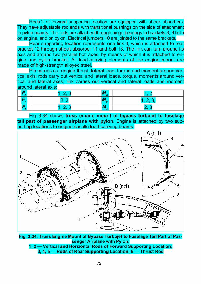
72
Rods 2 of forward supporting location are equipped with shock absorbers. They have adjustable rod ends with transitional bushings on the side of attachment to pylon beams. The rods are attached through hinge bearings to brackets 8, 9 both on engine, and on pylon. Electrical jumpers 10 are jointed to the same brackets.
Rear supporting location represents one link 3, which is attached to rear bracket 12 through shock absorber 11 and bolt 13. The link can turn around its axis and around two parallel bolt axes, by means of which it is attached to en-gine and pylon bracket. All load-carrying elements of the engine mount are made of high-strength alloyed steel.
Pin carries out engine thrust, lateral load, torque and moment around ver-tical axis; rods carry out vertical and lateral loads, torque, moments around ver-tical and lateral axes; link carries out vertical and lateral loads and moment around lateral axis:
xF 1, 2, 3 xM 1, 2 yF 2, 3 yM 1, 2, 3, zF 1, 2, 3 zM 2, 3
Fig. 3.34 shows truss engine mount of bypass turbojet to fuselage tail part of passenger airplane with pylon. Engine is attached by two sup-porting locations to engine nacelle load-carrying beams.
Fig. 3.34. Truss Engine Mount of Bypass Turbojet to Fuselage Tail Part of Pas-
senger Airplane with Pylon: 1, 2 — Vertical and Horizontal Rods of Forward Supporting Location;
3, 4, 5 — Rods of Rear Supporting Location; 6 — Thrust Rod

73
Forward supporting location consists of two rods 1, 2, attached on one side to brackets of load-carrying beam by hinge bearings, and on the other side to one bracket on engine casing. Vertical rod 1 carries out a part of vertical load and moment around lateral axis, horizontal rod 2 carries out a part of lateral load and moment around vertical axis.
Rear supporting location consists of four rods, three of them (3, 4, 5) lie in plane of supporting location and carry out full torque, the rest part of vertical and lateral loads, moments around vertical and lateral axes, and the fourth rod (6) carries out engine thrust and transmits it to engine nacelle longitudinal beam:
xF А, Б 6, 2, 3, 5 xM Б 3, 4, 5 yF A, Б 1, 4 yM A, Б 2, 3, 5
zF A, Б 2, 3, 5 zM A, Б 1, 4 All rods are made of high-strength alloyed steel, and have adjustable rod
ends on one side (adjustment pitch is a half of pitch of thread). Fig. 3.35, a shows truss engine mount of side bypass turbojets to fu-
selage tail part of middle passenger airplane with pylons, and Fig. 3.35, b shows truss engine mount of middle bypass turbojet in fuse-lage tail part of the same airplane. As these engine mounts are very similar, we shall consider them together. Each side engine is attached to engine na-celles frames (but middle one to fuselage frames) by two supporting locations.
Forward supporting location of side engine consists of four rods 3, 4, 5, 7. Three of them lie in plane of frame and are attached to it, but rod 7 connects engine with longitudinal beam 2 of pylon and serves for thrust force carrying out.
Rear supporting location of side engine consists of two rods 8, 9, lying in plane of rear strong frame.
Each rod of forward supporting location represents steel tube (Fig. 3.36), to which stamped steel eye-type rod end 5 is welded on engine side. Outer race 24 of hinge bearing is installed inside it. This race 24 is locked from turn with pin 18 and is pressed to rod end 5 with nut 22. The nut 22 in turn is locked with rivet 23. To install conical engine trunnion 25, inside race 24 there is inner race 19 of hinge bearing with conical hole,. Conical trunnion shape simplifies engine installation/removal. Rod end 5 is pressed to engine trunnion with nut 20. Rod 4 end on engine side has additional eye to connect thrust rod 7, the other end of which is attached to bracket on longitudinal beam 2.
On airframe side, the rods have adjustable fork-type rod ends 31, which are attached to brackets 30 through hinge bearings 27, 29. Minimal adjusting pitch in this case is equal to the half of thread pitch. All rod elements are made of high-strength steel. Internal surface of rods, excepting thread, is painted with primer АЛГ-14. External surface is painted with black enamel.

74
Fig. 3.35. Truss Engine Mounts of Bypass Turbojet to Passenger Airplane а — for Side Engines with Pylons; б — for Middle Engine in Fuselage;
1, 11, 12, 13 — Fuselage Frames; 2, 14, 15 — Beams; 3 — Bottom Rod; 4 — Ver-tical Rod; 5 — Upper Rod; 6 — Forward Strong Frame of Nacelle; 7 — Thrust Rod; 8 — Rear Side Rod; 9 — Rear Vertical Rod; 10 — Rear Strong Frame of
Nacelle; 16, 21, 34, 42, 46 — Washers; 17, 30 — Brackets; 18 — Pin; 19, 27, 47 — Inner Races of Hinge Bearings; 20, 22, 32, 35, 41, 45, 48 — Nuts;
23 — Rivet; 24, 29 — Outer Races of Hinge Bearings; 25 — Trunnion; 26, 28, 39, 50, 51 — Bolts; 31 — Fork; 33, 44 — Support; 36 — Sleeve; 43 — En-
gine; 49 — Eye Rear vertical rod 9 is a bolt made of high-strength steel. Its bottom end is
threaded in bracket 17 of rear attachment fitting and locked with nut 48. Upper rod 9 end is shaped as a cone and installed in conical hole of inner race 47 of hinge bearing, outer race of which is a support 44, attached to engine nacelle strong frame. Upper rod 9 end is fixed with nut 45 from axial displacement.

75
Fig. 3.36. Engine Mounts Elements of Bypass Turbojets in Fuselage Rear Part

76
Rear side rod 8 consists of fork, threaded in clamp, and locked with nut. The fork is attached to eye of engine bracket 17 with bolt 50. The clamp is at-tached to bracket of engine nacelle rear strong frame through spacer and hinge bearing. Bracket 17 is attached to fork 49 on strong casing of rear engine bear-ing support.
Engine thrust is carried out by thrust rod 7, but due to level between en-gine axis and rod 7 attachment point on engine, moment around vertical axis appear, which is carried out by two pairs of rods: 3 and 5 in forward supporting location and 8, 9 in rear one. Rods 3, 5 of forward and rods 8, 9 of rear support-ing location take part in all loads carrying out. Vertical rod 4 takes part in carry-ing out of vertical load, torque and moment around lateral axis:
xF A+D 7, 3, 5, 8, 9 xM А+D 3, 4, 5, 8, 9 yF А+D 3, 4, 5, 8, 9 yM A+D 3, 5, 8, 9
zF A+D 3, 5, 8, 9 zM А+D 3, 4, 5, 8, 9
Forward supporting location of middle engine consists of five rods 4, 5, 7 (4 and 7 are two pairs). As in side engine mounts, rods 4 and 5 lie in strong frame plane, but thrust rods 7 attach engine to fuselage longitudinal beams 15.
Rear supporting location of middle engine is one rod 9. Structure of mid-dle engine mount rods is similar to corresponding rods of side engine mount.
Middle engine thrust is carried out by thrust rods 7 only, because of en-gine mount symmetry. As rear supporting location can not carry out lateral load, than the same rods 7 carry out full moment around vertical axis, including mo-ment from lateral load action. Vertical rods 4 take part in carrying out of vertical load, torque and moment around lateral axis. Upper rod 5 takes part in carrying out lateral load and torque. Rear vertical rod 9 takes part in carrying out of ver-tical load and moment around lateral axis:
xF A 7 xM А 4, 5 yF А+E 4, 9 yM A 7
zF A 5, 7 zM А+E 4, 9
Each of these two engine mounts consists of six rods and is statically de-terminable. During engine installation/removal, rods remain attached to air-frame. They are detached from conical engine trunnions and turned sideways owing to hinge bearings.
3.3.8. Engine Mounts of (Bypass) Turbojets Under Wing with Pylon Engine mount of bypass turbojet under wing of passenger airplane
with pylon is shown in Fig. 3.37. It is truss in normal situation. The engine mount is formed by two supporting locations. In the forward
supporting location, engine brackets 14 are attached to eyes of forward bracket 2, 3 with bolts 13. The forward bracket 2, 3 transmits loadings to forward

77
bracket 1 of pylon 4. To provide survivability, forward bracket 2, 3 is made of two halves 2 and 3. From one side, bracket 14 has link to connect with forward bracket 2, 3. There is a reserve node in the middle of the forward bracket 2, 3. This reserve node consists of reserve bracket 12, reserve bolt 11, nut and washer. Reserve bracket 12 is arranged at some distance from the forward bracket 3, which prevents it from carrying-out thrust in normal engine mount op-eration. Reserve bolt 11 is also arranged in the hole of reserve bracket 12 with ra-dial clearance, which prevents it from carrying-out vertical and lateral loads in normal situation.
Bracket for thrust rod 5 is arranged on the engine casing slightly behind the reserve bracket 12. The other end of thrust rod 5 is attached to rear pylon bracket 6. Thrust rod 5 is provided with turn-buckle for rigging.
Triangle bracket 20 used instead of two rods is attached to rear pylon bracket 6 with two bolts. Third vertex of the triangle bracket 20 is attached to transverse beam 17, attached on the engine with two links 21 and one reserve bolt 22. Links 21 are bolted to fork of transverse beam 17 on one side and to engine flange on the other side. Reserve bolt 22 connects transverse beam 17 directly to engine flange. This reserve bolt 22 is normally unloaded, owing to radial clearance between it and transverse beam 17. In addition, triangle bracket 20 is connected to transverse beam 17 by adjustable rod 16.
In normal condition, the engine mount works as follows: thrust rod 5 car-ries out thrust; engine brackets 14 carry out vertical and lateral loads, moments around vertical and lateral axes, and also torque; triangle bracket 20 together with adjustable rod 16 carries out the rest part of vertical and lateral loads, moments around both axes and torque.
In case of thrust rod 5 failure, axial clearance between reserve bracket 12 and forward bracket 3 will be taken up under the action of engine thrust (or clearance between bracket 12 and nut of bolt joint will be taken up under the action of engine thrust reverse). So, thrust will begin to be transmitted through reserve bracket 12 and forward bracket 2, 3.
In case of one of the engine brackets 14 failure under the action of verti-cal or lateral loads, radial clearance between reserve bracket 12 and bolt 11 will be taken up, thereafter reserve bracket 12 begin to carry out these loads:
xF А, Б 5, 14, 20, 16, (12) xM А, Б 14, 20, 16, (12, 22) yF A, Б 14, 20, 16, (12, 22) yM A, Б 14, 20, 16, (12, 22)
zF A, Б 14, 20, 16, (12, 22) zM A, Б 14, 20, 16, (12, 22)

78
Fig. 3.37. Engine Mount of Bypass Turbojet Under
Wing of Passenger Airplane with Pylon: 1 — Forward Bracket of Pylon; 2, 3 — Forward and Rear Parts of Forward
Bracket; 4 — Pylon; 5 — Thrust Rod; 6 — Rear Bracket of Pylon; 7 — Pin; 8 — Bolt; 9 — Locking Wire; 10 — Nut, Carrying Tensile Stresses; 11 — Reserve Bolt; 12 — Reserve Bracket; 13 — Bolt; 14 — Engine Bracket; 15 — Forward Hoist Fitting; 16 — Adjustable Rod; 17 — Transverse Beam; 18 — Rear Hoist Fitting; 19 — Electrical Jumper; 20 — Triangle Bracket; 21 — Link; 22 — Re-
serve Bolt
79
Finally in case of one of links 21 failure, engine keeps attached to trans-verse beam 17 by the other link and reserve bolt 22.
Fig. 3.38 shows truss-girder engine mount of bypass turbojet under wing of super-heavy transport airplane with pylon. The engine mount is formed by two supporting locations.
Forward supporting location consists of supporting bracket 7, thrust bracket 2, forward link 5 and fasteners. Supporting bracket 7 is rigidly attached to engine flange and provided with hinge bearing 10, eyes 6 to connect link 5 and reserve eyes 3. Thrust bracket 2 has attachment flat with guide pin, center-ing hole and built-in nuts to attach to airplane pylon rigidly. Thrust bracket 2 is attached to supporting bracket 7 hinge-like, by means of pin 11, entering into bearing 10, eyes 4, link 5 with spherical races 12 and fasteners.
There is a hole in the thrust bracket 2, coaxial with reserve eyes 3 of sup-porting bracket 7. Reserve pin 9 is centered by hole in reserve eyes 3. Diame-ter of hole in thrust bracket 2 is much greater than pin 9 diameter, it forms a clearance, preventing reserve pin 9 loading possibility under normal engine mount operation. In case of one of the strongly loaded elements of forward supporting location failure (eyes 6, 4, pin 11, pins 13, link 5), this clearance will be taken up by engine displacement, and reserve eyes 3 with pin 9 will begin to work.
There is rubber sealing ring 1 on the thrust bracket 2 to fill the clearance between the bracket and socket in engine casing external shell and to separate cavities of upper pylon strut and engine nacelle space.
Rear supporting location consists of rear bracket 8, transverse beam 15, link 20, bracket 18 and fasteners.
Rear bracket 8 has attachment flat with guide pin, conical centering hole and built-in nuts for rigid attachment to airplane pylon, and eyes for attachment with transverse beam 15. Transverse beam 15 is movable link, providing engine axial displacement relatively airplane pylon.
Transverse beam 15 is attached to rear bracket 8 and to bracket 18 and link 20, installed on rear engine flange, by means of multiple shear eyes 17 and fasteners with spherical races 12. Transverse beam 15 has reserve eyes 16, which are used, in case of one of the most strongly loaded elements of rear supporting location failure (eyes 17, link 20, pins 13). In normal operation of rear supporting location, there is a clearance between reserve eyes 16 and re-serve pins 21.
There is a central hole in the transverse beam 15 of rear supporting loca-tion, for airplane communication system passing through between engine and pylon. Electrical jumpers 14, connecting supporting locations with airplane py-lon, and brackets for their connection are foreseen in the forward and rear sup-porting locations to provide engine electrical bonding.

80
Fig.
3.3
8. T
russ
-Gird
er E
ngin
e M
ount
of B
ypas
s Tu
rboj
et U
nder
Win
g of
Sup
er-H
eavy
Tra
nspo
rt A
irpla
ne w
ith P
ylon
: 1
— S
ealin
g R
ing;
2 —
Thr
ust B
rack
et; 3
— R
eser
ve E
yes
of S
uppo
rting
Bra
cket
; 4 —
Eye
s of
Thr
ust B
rack
et; 5
—
Forw
ard
Link
; 6 —
Eye
s of
Sup
porti
ng B
rack
et; 7
— S
uppo
rting
Bra
cket
; 8 —
Rea
r Bra
cket
; 9 —
Pin
; 10
— H
inge
Bea
r-in
g; 1
1 —
Pin
; 12
— S
pher
ical
Rac
e; 1
3 —
Pin
; 14
— E
lect
rical
Jum
per;
15 —
Tra
nsve
rse
Bea
m; 1
6 —
Res
erve
Eye
s of
B
rack
et; 1
7 —
Eye
s of
Tra
nsve
rse
Bea
m; 1
8 —
Bra
cket
; 19
— H
oist
Bra
cket
s; 2
0 —
Rea
r Lin
k; 2
1 —
Res
erve
Pin

81
Pin 11 of forward supporting location carries out thrust, lateral load and moment around vertical axis. Link 5 carries out vertical load and moment around lateral axis. Bracket 18 together with link 20 carries out full torque and the rest part of vertical and lateral loads, moments around vertical and lateral axes. Reserve pin 9 can carry out thrust, vertical and lateral loads, moments around vertical and lateral axes:
xF А, Б 11, 5, 20, 18, (9) xM А, Б 20, 18, (21) yF A, Б 5, 20, 18, (9, 21) yM A, Б 11, 20, 18, (9, 21)
zF A, Б 11, 20, 18, (9, 21) zM A, Б 5, 20, 18, (9, 21)
Fig. 3.39 shows truss-girder engine mount of turbojet under wing of passenger airplane with pylon.
Engine is attached by two supporting locations in three points. In the for-ward supporting location, two pairs of links 3, hinged to engine flange, form two nodes, in those two conical bolts 2, 4 are hinged. These bolts enter into conical holes of forward pylon bracket 1 by its conical part. Threaded bolt ends are at-tached to bracket 1 with nuts. Forward bracket 1 carries out and transmits a part of vertical and lateral loads, both moments and torque to pylon. Thrust force is carried out by two thrust rods 5, hinged directly on the conical sockets of bracket 1:
xF А, Б 2, 4 xM А, Б 2, 4 yF A, Б 2, 4, 9 yM A, Б 2, 4, 9
zF A, Б 2, 4, 9 zM A, Б 2, 4, 9
Rear supporting location consists of two rear links 6, hinged to rear en-gine flange and forms a node. This node is connected through universal joint 7 and rear conical bolt 9 to rear bracket 8, hinged on rear pylon brackets 10. So, rear supporting location does not carry out any axial load from engine thermal expansion, owing to universal joint 7 and hinged connection between brack-ets 8 and 10. Rear supporting location carries out the rest part of vertical and lateral loads, and also moments around vertical and lateral axes.
Fig. 3.40 shows truss-girder engine mount of bypass turbojet under wing of passenger airplane with pylon.
In this case, engine is attached by two supporting locations. Forward one consists of forward bracket 1 with two forward links 2, 3, those are attached to brackets 4 on engine fan casing. Forward links 2, 3 carry out a part of vertical and lateral loads, moments around vertical and lateral axes, and also torque. Thrust bracket 5 is also arranged in the forward supporting location. Thrust rod 6, transmitting load from engine thrust to rear bracket 7 connected with py-lon, is attached to the thrust bracket 5.

82
Fig. 3.39. Truss-Girder Engine Mount of Turbojet Under Wing of Passenger Air-
plane with Pylon: 1 — Forward Pylon Bracket; 2 — Right Conical Bolt; 3 — Link;
4 — Left Conical Bolt; 5 — Thrust Rod; 6 — Rear Links; 7 — Universal Joint; 8 — Rear Bracket; 9 — Rear Conical Bolt; 10 — Rear Pylon Bracket
Rear supporting location consists of rear bracket 7, two rear links 8 and reserve eye 9 with stops 10, and fasteners. In normal operation, two rear links 8 carry out the rest part of vertical and lateral loads, moments around ver-tical and lateral axes and torque.

83
Fig. 3.40. Truss-Girder Engine Mount of Bypass Turbojet Under Wing of Pas-
senger Airplane with Pylon In case of thrust rod or thrust bracket or fasteners connecting them fail-
ure, stops 10 of reserve eye 9 will be used. One of the stops (forward at direct thrust or rear at thrust reverse) will abut onto inner surface of rear bracket 7 and thus will transmit thrust to it.
In case of one of the rear links 8 failure, reserve eye 9 and reserve bolt 11 will be used. Those can transmit vertical and lateral loads, and take part in carrying-out of moments around vertical and lateral axes and torque.
In case of one of the forward links 2, 3 failure, reserve bracket 12, con-necting engine directly with forward bracket 1, will be used. Reserve bracket 12

84
can carry out vertical and lateral loads, moments around vertical and lateral axes, and also torque. In normal operation, reserve bracket is separated from forward bracket with clearance and does not carry out any loads.
3.4. Afterburner Attachment Features The feature of extension pipes and afterburners attachment is their sig-
nificant temperature deformations at heating up to high temperature. To elimi-nate thermal stresses in thin shells of afterburners and extension pipes, it is necessary to attach them so, that significant displacement of attachment points is provided. One of the solutions of this problem is guide rails and rollers appli-cation. Another solution can be installation of rods with hinge bearings in the plane, perpendicular to afterburner axis. From the forward, extension pipes and afterburners are usually attached to rear engine flange by telescopic joint, pro-viding engine axial thermal deformations without thermal stresses appear. Let us consider a number of examples.
Afterburner attachment of maneuverable airplane is shown in Figs 3.24, 3.41.
Fig. 3.41. Afterburner Attachment of Maneuverable Airplane: 1 — Rails; 2 — Left Roller; 3 — Right Roller; 4 — Bushings;
5 — Roller Flange From the forward, the afterburner is attached to engine by telescopic joint.
On the other side the afterburner is attached to fuselage by guide rails 1, in-
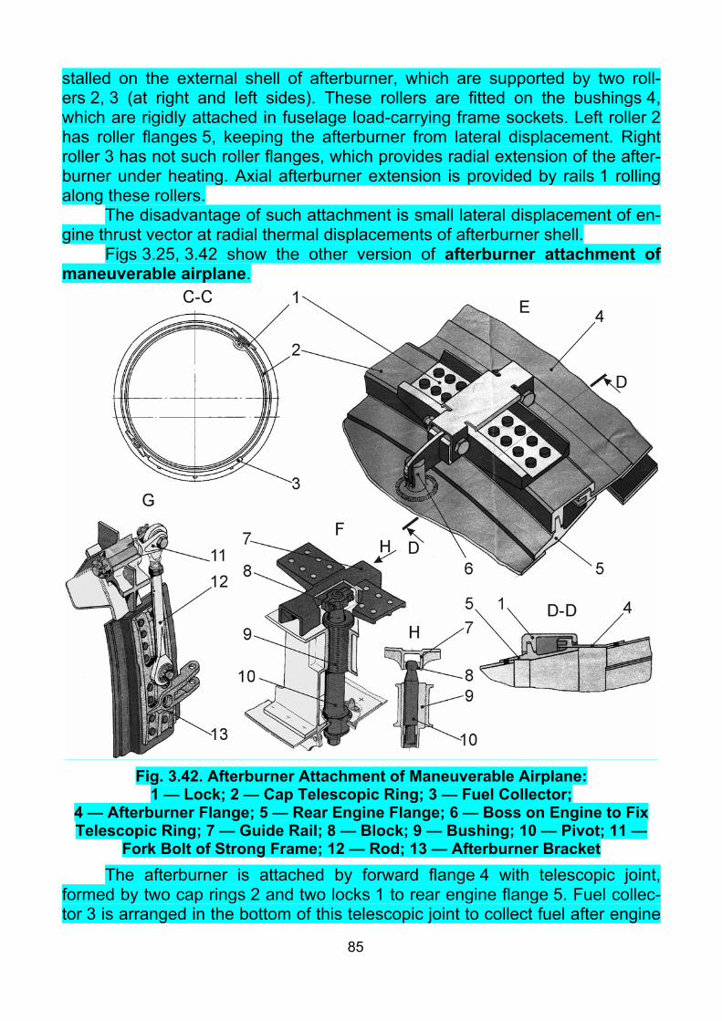
85
stalled on the external shell of afterburner, which are supported by two roll-ers 2, 3 (at right and left sides). These rollers are fitted on the bushings 4, which are rigidly attached in fuselage load-carrying frame sockets. Left roller 2 has roller flanges 5, keeping the afterburner from lateral displacement. Right roller 3 has not such roller flanges, which provides radial extension of the after-burner under heating. Axial afterburner extension is provided by rails 1 rolling along these rollers.
The disadvantage of such attachment is small lateral displacement of en-gine thrust vector at radial thermal displacements of afterburner shell.
Figs 3.25, 3.42 show the other version of afterburner attachment of maneuverable airplane.
Fig. 3.42. Afterburner Attachment of Maneuverable Airplane:
1 — Lock; 2 — Cap Telescopic Ring; 3 — Fuel Collector; 4 — Afterburner Flange; 5 — Rear Engine Flange; 6 — Boss on Engine to Fix Telescopic Ring; 7 — Guide Rail; 8 — Block; 9 — Bushing; 10 — Pivot; 11 —
Fork Bolt of Strong Frame; 12 — Rod; 13 — Afterburner Bracket The afterburner is attached by forward flange 4 with telescopic joint,
formed by two cap rings 2 and two locks 1 to rear engine flange 5. Fuel collec-tor 3 is arranged in the bottom of this telescopic joint to collect fuel after engine

86
unsuccessful start. On the rear side the afterburner is attached to fuselage strong frame in three points: by two rods 12 and by guide rail 7. Two adjustable rods 12 are hinged to fork bolts 11 on the strong frame and are connected with brackets 13 to the afterburner upper part. Pivot 10 is rigidly attached in the middle bottom of the strong frame. Guide rail 7 of the afterburner can slide along this pivot. Pivot 10 carries out lateral load and provide engine thrust vec-tor coincidence with horizontal projection of airplane axis. For this purpose, pivot is threaded in eccentric bushing 9, allowing to adjust afterburner axis posi-tion in lateral direction during rigging. There is a block 8 at the end of pivot 10, contacting with guide rail 7.
Figs 3.26, 3.43 show two afterburners attachment inside fuselage of altitude-airspeed airplane.
Fig. 3.43. Two Afterburners Attachment Inside Fuselage
of Altitude-Airspeed Airplane: 1 — Eccentric Roller; 2 — Fuselage Guide Rails; 3 — Bottom Pivot; 4 — Exten-
sion Pipe Guide Rail; 5 — Block; 6 — Eccentric Bushing; 7 — Streamer; 8 — Vertical Streamer Slots; 9 — Pin; 10 — Hinged Support
In the forward part, extension pipe of afterburner is attached by telescopic joint to rear engine flange. In the rear part, the pipe is supported on fuselage guide rails 2 through two eccentric rollers 1. Each guide rail 2 is bolted with two fuselage frames. Eccentric rollers 1 allow to adjust jet nozzle position in vertical direction. Extension pipe fixing in lateral direction, and also its rigging is pro-vided by bottom pivot 3, which slides in guide rail 4 of extension pipe. There are technological flats on the pivot 3 to simplify assembling. Block 5 is made mono-lithic, bushing 6 is made as eccentric, which allows to eliminate mounting stresses in the block during pivot installation.
To reduce fuselage tail part mid-section, engine jet nozzles are brought together so that distance between their axes is lower than jet nozzle diameter

87
(ref. cross-section D-D). It requires to remove three segments of external flaps of each jet nozzle, and to arrange between them nonadjustable element — streamer 7 to keep jet nozzles counters closed. External flaps of both engine jet nozzles are closed on the streamer.
Streamer 7 of engine jet nozzles, which installed instead removed flaps, is connected to eyes on external flaps attachment rings of left and right jet noz-zles and moves together with rings during engine rigging. Telescopic joint of the streamer allows to keep its correct position at separate jet nozzles regula-tion or in case one of the engines fails in flight. To prevent streamer turn, verti-cal slots 8 are provided in the top and bottom of its rear part. Pins 9 with hinged support 10 enter in these slots.
Checklist 1. What is the purpose of engine nacelle? 2. List the requirements to engine nacelles. 3. Characterize the frame scheme of cowling. 4. Characterize the panel scheme of cowling. 5. Characterize typical piston engine nacelle. 6. Characterize typical turboprop engine nacelle. 7. Characterize typical (bypass) turbojet engine nacelle. 8. What is the purpose of engine mount? 9. What types of engine mount airframes do you know? 10. What is fail-safe structure? 11. List main requirements to engine mount. 12. List loads to be taken into account during engine mount designing. 13. What mass is used to calculate mass forces, acting on engine mount? 14. How to determine gyroscopic moment? 15. How to determine the direction of gyroscopic moment? 16. How to determine reaction torque from a propeller? 17. How to determine reaction torque from coaxial contra-rotating propellers? 18. How to determine thrust force for a piston engine or a turboprop? 19. How to determine mass loadings? 20. List main normative papers, according to which numerical values of
loadings on engine mount are determined. 21. Characterize critical load condition 1. 22. Describe typical engine mount of radial piston engine. 23. What is the difference between frame and truss engine mounts of ra-
dial piston engines? 24. What materials are used in engine mount? 25. How to classify engine mounts of in-line piston engines? 26. How to classify engine mounts of turboprops? 27. What are hinge bearings in rod ends foreseen for? 28. What is the reason of wide application of turboprops double-span en-
gine mount?

88
29. Describe typical truss engine mount of turboprop. 30. Why are turboprop attachment trunnions sometimes made split? 31. Describe possible version of truss-girder engine mount of turboprop. 32. Describe possible version of truss-girder engine mount of (bypass)
turbojet in fuselage. 33. How to provide engine rigging? 34. What is it necessary to foresee to provide stepless rigging. 35. What are check holes in threaded parts of rods and transitional bush-
ings intended for? 36. How to provide adjustable rods locking? 37. What is the feature of engine rigging in case of statically indetermin-
able engine mount? 38. How to provide engine installation and removal inside fuselage of ma-
neuverable airplanes? 39. Describe possible version of engine mount of (bypass) turbojet to fu-
selage without pylon. 40. Describe possible version of engine mount of (bypass) turbojet to tail
part of fuselage with pylon. 41. Describe possible version of engine mount of (bypass) turbojet under
wing with pylon. 42. Give examples of fail-safe structures in engine mounts. 43. In what way and what for is engine mount electrical bonding provided? 44. What is undertaken to prevent thermal stresses in load-carrying ele-
ments of engine and engine mount? 45. Describe features of extension pipe and afterburner attachment.

89
Theme 4. VIBRATIONS OF POWER PLANTS. SHOCK–ABSORPTION OF ENGINE MOUNT
4.1. Types of Vibrations. Causes of Vibrations. Effects of Vibrations Process of periodic change of some generalized coordinate in time is
called vibrations (oscillations). The number of oscillations which is carried out by a system in a unit of time is called frequency of oscillation. Maximum devia-tion from an equilibrium position is called amplitude of oscillation (vibrational amplitude).
There are free and forced oscillations. Free oscillations are these which occur after some initial disturbance of equilibrium state of a system which af-terwards remains as it is (Fig. 4.1, a).
Forced oscillations are performed under influence of the given shaking forces. The forced vibration frequency is equal to frequency of the shaking force (Fig. 4.1, b).
a b Fig. 4.1. Free and Forced Oscillations
The amplitude of oscillation sometimes reaches such value that it compli-cates a normal operation of instruments and gears and can cause breaking of structure elements. Vibrations reduce the service life and reliability of parts and equipment and frequently cause fatigue failures of a structure.
One of the main sources of oscillations on airplanes and helicopters is power plant (in particular engines and propellers or rotors).
The engine and propeller or rotor create vibrations of two types: mechani-cal and acoustical.
The reasons of vibrations of the engines are as follows: – Non-uniformity of torque of piston engines; – Unbalance of inertial force of a translational and a rotary motion of en-
gine parts; – Static and dynamic unbalance of rotating engine parts. The reasons of vibrations of a propeller are its static, dynamic and aero-
dynamic unbalances. The static unbalance of a propeller (Fig. 4.2, a) appears when the center
of mass of a propeller does not coincide with its axis of rotation. Value of this

90
noncoincidence is determined by the tolerance on static balance of a propeller. The dynamic unbalance of a propeller (Fig. 4.2, b) appears when the axis
of rotation of a propeller does not coincide with one of its principal centroidal axes. It happens in a case, when centers of mass of separate blades lie in dif-ferent planes, normal to axis of rotation. Thus an unbalanced couple of forces, concerning y and z axes, appears.
a b c
Fig. 4.2. Propeller Unbalances The aerodynamic unbalance of a propeller (Fig. 4.2, c) appears, if aero-
dynamic forces of separate blades have various values or directions. It hap-pens, if:
– blades have various blade angles; – centers of pressure of blades are located on various distances from the
axis of rotation; – there is stall phenomena on blades, which cause oscillations of blades,
under big angles of attack; – there is interference of a propeller with parts of aircraft arranged behind
or in front of propeller (a wing or a fuselage). The shaking forces, appearing when a power plant is under operation, are
periodic one. Their frequency is multiply to the rotational speed of parts of the engine or the propeller. Thus a ratio of frequency of free oscillation p to fre-quency of shaking force shω is of great importance.
Oscillation frequency shω of the engine (propeller) linearly depends on ro-tational frequency of engine rotor (propeller). The harmonic order of shaking forces and shaking moments of the engine in relation to rotational frequency of crankshaft of piston engine or rotor of turbojets makes:

91
– for piston engines: 0.5, 1, 2, 0.5(а+1), where a — number of cylinders; – for turboprops and turbojets: 1, 2,... The order of propeller harmonics for a k-bladed propeller is: 1, 2... k, mk,
where m = 2, 3,... The most dangerous are vibrations with frequencies n, 2n for piston-
engined airplanes; n for turbojet airplanes; np, 2np for turboprop airplanes, where n and np — rotational frequencies of the rotor of engine and the propeller accordingly.
It is necessary to note, that in flight the rotational frequency of the engine and propeller varies almost continuously and forms an area of low frequencies. From the point of view of vibrations, piston engines are the most dangerous ones. Power plants with turbojets are more favorable, because the frequencies of forced oscillations are higher and the rotating masses are better balanced. Turboprops take an intermediate place between turbojets and piston engines.
Vibrations can cause: Decrease of service life and reliability of vibrating parts because of fatigue
of materials. – Increase of wear and appearance of backlashes. – Disturbance of pressure–sealings of pipelines and systems. – Problems in operation of instruments and observation of them. – Discomfort for passengers and crew. In this event the vibrations can be
unacceptable earlier, than they achieve the dangerous values for a structure. – Possibility of resonance. Thus the amplitude of movements and
stresses in the structure sharply increase. An engine as a solid body, hinged to aircraft with elastic three-
dimensional truss, is a system with six degree of freedom. These are three translations in a direction of three axes and three angular movements around these axes. Hence, we have six frequencies of free oscillations.
Depending on arrangement of the center of mass of engine and elastic center of engine mount they distinguish:
– separated oscillations — at coincidence of the center of mass of en-gine and the elastic center of engine mount;
– doubly connected oscillation — when the center of mass and the elastic center lie in axis of rotation of propeller or main rotor;
– triply connected oscillation — generally. At separated oscillations, frequencies of free oscillations of engine are in
a narrow range. Coincidence of the center of mass and the elastic center is provided by a change of shock absorber’s stiffness of engine mount. Usually there are triply connected oscillations, hence movement along one of the axes causes movements and turns around all other axes. Further we achieve a separation of the oscillations by changing the stiffness of shock absorbers and the stiffness of engine mount. Thus there is a capability to change any fre-quency of free oscillations to eliminate a resonance, not changing natural fre-quency in other directions.

92
4.2. Stiffness of Engine Mount The stiffness of engine mount is determined by calculation or experimen-
tal ways. For this purpose, the unit generalized force is applied in the center of mass of the engine in the direction of the required axis and the corresponding
generalized movement is found. The inverse values to these movements make stiffness of engine mount. The stiffness of a shock absorber is a derivative (Fig. 4.3)
ϕ=δ
= tgddPK
shsh ,
where P — external loading; shδ — motion of the shock absorber caused by this loading.
A stiffness of engine mount together with shock-absorption along or around one axis is deter-
mined as harmonic average of their stiffnesses:
shmPP K1
K1
K1
+=.
; shm
shmPP KK
KKK+
=. ,
where mK and shK — the stiffnesses of engine mount and shock-absorption along or around the specified axis.
Knowing the design of engine mount, the type and arrangement of shock absorbers, it is possible to determine the frequency of natural oscillations of the system. In case of triply connected oscillation, the exact solution of this problem presents difficulties because of necessity to find roots of secular equation (in this case it presents algebra equation of the sixth order). It results in wide ap-plication of approximate methods of natural frequency determination. In the simplest case, for separated oscillations these frequencies are determined un-der the following formulas:
MK
21 i
i π=ν ;
i
ii J
K21π
=ν ,
where M — mass of the engine; iJ — mass moment of inertia of the engine around of i axis.
4.3. Oscillations of System with One Degree of Freedom For an instance we shall consider oscillations of a system with one de-
gree of freedom (Fig. 4.4). In Fig. 4.4 it is designated: K — stiffness of the spring; M — mass; λ —
drag coefficient; P — elastic force; I — inertial force; F — external force; X — drag; y — movement relative to the equilibrium position.
Fig. 4.3. Stiffness of
Shock Absorber

93
( )
.;;
;sin
yKPyXyMI
tFF 0
⋅=⋅λ=⋅=
ω⋅=
&
&&
Fig. 4.4. Oscillating System with One Degree of Freedom
Let the external force change under the harmonic law: tFF 0 ω= sin . Then the equilibrium equation shall be written as: ;sin; tFKyyyMPXFyM 0 ω=+λ+−−= &&&&&
;sin;sin tqypy2ytMFy
MKy
My 20 ω=+κ+ω=+
λ+ &&&&&&
where MKp = — natural frequency of oscillations; M2 λ=κ , MFq 0= . The last equation is a linear nonhomogeneous differential equation of the
second order with constant factors. Its solution at entry conditions 0y0t
y ==
,
0y0t
y ′==
′ is well–known:
( )( )⎪⎩
⎪⎨⎧
+−κ
−κ⎥⎦
⎤⎢⎣
⎡
ωκ+ω−ω+−κω
+κ+′= κ−
22
22
2222
222
00t
ptp
4pp2qyyey sin
( )
+⎪⎭
⎪⎬⎫
−κ⎥⎥⎦
⎤
⎢⎢⎣
⎡
ωκ+ω−
κω++ tp
4pq2y 22
222220 cos
( ) ⎥
⎦
⎤⎢⎣
⎡ω−
κω−ω
ωκ+ω−+ 2222222 p
2t4p
q arctansin .
Here the first member represents natural oscillations, and the second one is forced oscillations. The amplitude of forced oscillations can be presented in the following view:
( )
=
⎟⎟⎠
⎞⎜⎜⎝
⎛ ω⎟⎟⎠
⎞⎜⎜⎝
⎛ κ+
⎟⎟
⎠
⎞
⎜⎜
⎝
⎛⎟⎟⎠
⎞⎜⎜⎝
⎛ ω−
=ωκ+ω−
=2222
2
22222F
pp4
p1
pq
4p
qA
( ) ( ) ( ) DYN
2222
ST
2222
0
2222
0 yxa4x1
y
xa4x1
KF
xa4x1
KMMF=
+−=
+−=
+−
⋅= ,

94
where KFy 0ST = — represents the movement caused by the statically apply-ing of the external force amplitude value; px ω= and pa κ= — is denoted for short.
Let's work in the concept of amplification factor (Fig. 4.5) as a relation of the amplitude of forced oscillations to the movement caused by the statically applied external force amplitude value:
( ) 2222ST
DYNDYN
xa4x1
1yyK
+−===µ .
On the diagram (Fig. 4.5) it is possible to find three zones:
Fig. 4.5. Amplification Factor
1) 222 2p κ−<<ω ; 1≈µ ; STDYN yy ≈ ; 2) 222 2p κ−≈ω ; 1>>µ ; STDYN yy >> ; 3) 222 2p κ−>ω ; 1<µ ; STDYN yy < . On the basis of this diagram it is possible to make the following conclu-
sions: 1. The coincidence of frequencies of forced and natural oscillations (the
second zone) is inadmissible. 2. The case, that the frequency of forced oscillation is smaller than the

95
frequency of natural one (the first zone), is allowable, but is undesirable. Thus there is a capability to hit in a resonance with higher harmonics of the shaking force. (It occurs in turboprop engine mount).
3. The case, that the frequency of forced oscillation is bigger than the fre-quency of natural one (the third zone), is desirable. As the amplitude of forced oscillations is less than the static values of movements.
4. Even at presence of drag (damping), the forced oscillations happen with a frequency of shaking force.
5. The amplitude of the forced oscillations does not depend on entry con-ditions and time. I. е. the forced oscillations are not damped.
6. At a resonance ( p=ω ) the amplitude of the forced oscillations remains
finite p2
qAF κ= . And the amplitude reaches a maximum in the other point
( 22 2p κ−=ω ), i.e. up to the resonance, and makes: 22
2
Fp2qpA
κ−κ= .
7. In the forced oscillations with drag, a shift of phase of oscillations
22F p2
ω−κω
=ϕ arctan , in comparison with the phase of shaking force, always
takes place. The maximal value of the phase shift 2Fπ
=ϕ , is reached at the
resonance. 8. Though amplitudes of the forced oscillations with drag remain finite
even at a resonance, under continuous work, in these conditions fatigue fail-ures of elements of the design are probable.
4.4. Shock-absorption of Engine Mount. Essence and Purpose of Shock-Absorption. Shock Absorber Installation Place
To decrease vibrations and forces in engine mount it is necessary: – To decrease the values of shaking forces by improvement of balancing
of engine and propeller; – To decrease tolerance for blade angles of separate blades of variable
pitch propeller; – To apply dampers — the oscillation absorber which dissipate a signifi-
cant part of the energy of oscillation; – To select the stiffness of engine mount and shock absorbers for elimi-
nation of a resonance. The essence of shock–absorption is that the engine is attached to the air-
craft structure not stiffly, but through elastic joints (shock absorbers) which sharply reduce the oscillation frequency of power plant.
Shock absorbers are installed in the attachment fittings of the engine mount to the engine or in the attachment fittings of engine mount to aircraft structure. The second way is undesirable, since shaking loads act directly to

96
engine mount here; there is a danger of a resonance. Besides the distance from the engine center of mass up to shock absorbers is more, hence, the loads, which act to shock absorbers, are more too.
The struts–dampers are installed in the engine mount for shock-absorption. Sometimes the shock absorbers are installed in both attachment fittings of engine mount to engine and in attachment fittings of engine mount to aircraft structure. Thus the complete separation of the aircraft structure from vi-brations of engine is reached.
At oscillations around y and z axes (normal to propeller axis) there is a gyroscopic precession oscillation, which is very harmful to propeller and to ro-tating rotor of engine. They are caused by a gyroscopic effect of the propeller and the rotor of the engine. To decrease them, the stiffness around these axes is limited by required minimum.
The greatest shaking forces act along y and z axes and around x axis. The most effective shock-absorption is installed for their absorption. The stiff-nesses in other directions are several times (up to 10) higher.
The stiffness of engine mount is different in different directions. Accord-ingly, natural frequencies of oscillation and required stiffness of shock absorb-ers are different in different directions.
4.5. Structure of Shock Absorbers An elastic element of a shock absorber is usually rubber. The shear
modulus G connected with modulus of elasticity E and Poisson ratio µ by formula
( )µ+=12EG .
As far as Poisson ratio for rubber makes 460. , then shear stiffness of rubber shock absorber is in 922. times less than compression one. As it is known, stiffness of compressed element is equal to: LEFK = , where F — element cross–sectional area, L — its length.
So different stiffness in different directions is provided by different thick-ness or cross–section area of rubber along corresponding directions or by load-ing of rubber with compressive and shear loads. For example, in bushing–type shock absorbers, the thickness of rubber is different in different directions. In addition, that rubber carries compressive stresses or shear stresses depending on direction of loading.
Fig. 4.6. shows that, this design of shock absorber provides: – big angular motion around x axis, which protect engine mount and air-
craft from impulses of engine torque; – enough radial engine motion, which soften action of impulses from un-
balanced loads to aircraft;

97
– small motion along x axis, which is dangerous owing to precession propeller oscillation.
Shock absorbers of turboprops (Fig. 4.7 – 4.9) are arranged in a plane, which is parallel to axis of the engine. To provide small stiffness around x axis, the distance between shock absorbers by width should be small. And to pro-vide high stiffness around y and z axes, the distance between forward shock absorbers and struts–dampers should be big.
Fig. 4.6. Shock Absorber of Bush–type and Its Characteristics
Fig. 4.7. Disk Shock Absorber:
1 — Engine Trunnion; 2 — Bushing; 3 — Ring; 4 — Casing; 5 — Disk-type Shock Absorber; 6 — Bolt; 7 — Elec-trical Jumper; 8 — Cover; 9 — Pro-
tective Washer; 10 — spacing washerWhen selecting the place for shock absorber, it is necessary to take into
account, that fuel and oil act harmfully to rubber of shock absorber. Hence, shock absorbers should be protected with covers or casings. Besides the elas-tic properties and strength of rubber decrease at a temperature decreasing. To protect the shock absorbers from harmful effect of heat flows of jet engines they sometimes use a forced cooling of shock absorbers.
Strut-shock absorber (See Fig. 8.8) consists of casing 3 and central rod 9 with three disk-type shock absorbers 7 installed on it. Bushings 5, 6 are in-stalled among them, to use them in parallel. Next this pack is tightened in cas-ing 3 between its step and fork 1; and it is tightened on the central rod 9 be-tween central rod step and nut 4. Owing to bushings 5, 6, both compression and tension loads are transmitted through all three disk-type shock absorbers in parallel, which increases rigidity of strut-shock absorber as a whole. Fig. 8.9 shows another structural realization of the same scheme for strut-shock-absorber.

98
Fig. 4.8. Strut–damper:
1 — Fork; 2 — Retaining Screw; 3 — Casing; 4 — Nut; 5, 6, 8 — Bushings; 7 — Disk-type Shock Absorber; 9 — Central Rod; 10 — Transitional bushing;
11 — Locking Washer; 12 — Eye
Fig. 4.9. Strut-Shock-Absorber (Another Version):
1 — Caver with Fork; 2 — Rubber-Metal Ring; 3 — Casing; 4 — Hollow Rod; 5 — Turn-Buckle; 6 — Eye; 7 — Electrical Jumper
Checklist 1. What is vibration? What are the parameters, which characterize vibra-
tion? 2. What is free and forced vibration? 3. What are the reasons of engine vibration? 4. What are the reasons of propeller vibration? 5. What are the results of vibrations? 6. How to determine stiffness of engine mount? 7. What zones are usually distinguished on the amplification factor
graph? 8. What conclusions can be done from the amplification factor graph? 9. What ways to decrease engine mount vibration do you know? 10. What is the essence of shock-absorption? 11. Where is it desirable to install shock absorbers? 12. What ways are used to achieve different stiffness of shock absorbers
in different directions?

99
Theme 5. FUEL SYSTEMS OF POWER PLANT
5.1. Purpose of Fuel Systems and Requirements to Them The fuel system represents a complex of interacted subsystems in-
tended to feed the engine by fuel in all operating conditions allowable for this aircraft, moreover fuel systems can perform a number of additional functions (such as: cooling of oil, keeping specified center-of-gravity position, etc.).
The number of requirements is made to the fuel system. A part of which is general, and the other part depends on the type and purpose of the aircraft (supersonic, air tanker, etc.).
1. Reliable supply of fuel to all engines under all expected operation con-ditions of this aircraft on ground and in flight.
2. To ensure survivability and flight safety (including fire–prevention). – Fuel tanks must not be arranged near passenger cabin or crew. – All metal elements of a fuel system should be interconnected and also
connected to the aircraft (and to ground at parking) in order to prevent a dis-charge of a static electricity.
– Fuel system must be designed so to prevent fuel vapors ignition as a result of direct or indirect lightning stroke to zones, where probability of such stroke is big (for example, at a distance of 500 mm from the end, the wing should not be filled with fuel; to be on the safe side at lightning stroke).
– Fuel pipelines are desirable to be placed inside the fuel tanks. In case of a leakage, the fuel flows in the fuel tanks, instead of flowing in the airframe.
3. The fuel tanks should contain main fuel (required for flight with the specified maximum range or duration) and fuel reserve consisting of stand-by and compensating fuel reserves. Standby fuel reserve includes fuel required to fly from estimated point (decision height at approach in aerodrome of destina-tion) to supplementary aerodrome and flight in holding mode above supplemen-tary aerodrome during 30 min. Compensation fuel reserve is required to com-pensate mistakes of navigation accuracy, fuel-measurement systems and me-teorological conditions and it makes not less than 3 % of main fuel.
4. To maintain of the specified center–of–gravity position, fuel should be used in a specified sequence automatically. In case of failure of the automatics, there should be a capability of manual control by fuel tanks usage.
5. Fuel should be filtered from mechanical impurities and water. The wa-ter dissolved in fuel and allocated from it in the fuel tanks or in some elements of the fuel system, must not cause disturbance of fuel system operation.
6. It is necessary to provide protection of units of the fuel system from: corrosion, frosting-up, microorganisms, discharges of a static electricity, over-heating.
7. It is necessary to provide sufficient strength, vibration-proof and hermiticity. 8. It is necessary to provide full defueling on ground through easily ac-
cessible and convenient in maintenance valves.

100
9. It is necessary to provide the reliable and continuous control of the fuel system operation.
10. The fuel system should be simple in control, convenient in mainte-nance. Maintenance ground time of the fuel system should be minimal (it is called maintainability).
11. A fuel dumping (jettisoning) system must be installed on each airplane unless it is shown that the airplane meets the climb requirements at maximum takeoff weight.
5.2. Aviation Fuels and Their Properties The main fuel for up-to-date aviation piston engines and jet engines are
liquid mixes of hydrocarbons. They are recovered by gasolineeum refining. For jet engines aviation kerosene is used. Working process in the piston engines imposes limitations for the period of a mixing, firing and combustion of the fuel. Therefore easily inflammable fuel — aircraft petrol is applied for aviation piston engines.
The engine start-up, thrust, efficiency, reliability of operation, etc. depend on fuel quality.
Let's consider the main properties of fuels, which should be taken into ac-count when designing fuel systems.
1. Energy properties of fuel are determined by its heat of combustion and density.
Heat of combustion is a quantity of heat, which evolves at complete com-bustion of a unit of fuel mass. Heat of combustion of kerosene and petrol is ap-proximately equal to 4340042900... kJ/kg.
At a temperature of 20°C density of petrol makes 740720 .....=ρ kg/dm3, and of kerosene makes 8507550 .....=ρ kg/dm3.
Volumetric heat of combustion (energy content) is the product of density of fuel by its heat of combustion. Volumetric heat of combustion of kerosene is approximately 15% higher, than that of petrol. Hence, when storing the speci-fied mass of fuel onboard the aircraft, smaller tanks are required for the fuels with greater density.
The density of fuel depends on its temperature by the following relation (Fig. 5.1): ( )20t20t −α−ρ=ρ , where 20ρ — the density of fuel at a temperature 20°C; α — the temperature correction to the density ( 0009000070 .....=α kg/m3°С).
Decrease of the density when been heated resulting in increase of a vol-ume of the fuel. This fact shall be taken into account, when designing the fuel tanks. Otherwise there will be a pressing-out of fuel through the vent system. It can cause a fire. It is also inadmissible because we lose fuel.

101
Fig. 5.1. Dependence of Fuel Density on Its Temperature:
1 — for Fuel T-1; 2 — for Fuel T-5 2. Saturated vapor pressure (steam tension) of fuel is the important
characteristics of fuel. It determines their vaporability, impacts to the altitude performance of the fuel system. tP — the greatest vapor pressure, being above fuel, which is reached at vaporation into a closed vessel at the specified tem-perature.
Aviation fuels are multicomponent liquids. Their saturated vapor pressure in a fuel tank depends on a ratio of volumes of steam and liquid phases. When pressure decreases, light ends of fuel first pass in a gaseous state into the over–fuel space of the fuel tank. These light ends have a high saturated vapor pressure. Steam tension of the stayed fuel thus is reduced.
At vaporation in the closed volume, the equilibrium state steps with the greater steam tension of liquid end of fuel and the earlier, the smaller ratio of volumes of vapor and liquid phases is. The standard ratio of volumes of vapor and liquid phases is assumed equal 4/1. Thus saturated vapor pressure is des-ignated by 14tP .
Fuels with higher saturated vapor pressure (for example petrol) vapors faster. It improves start-up qualities of engines. Such fuels have low fire danger (on the base of experience).
It is explained by the following. In case of kerosene leakage, it is accumu-lated in the bottom places, which increases fire danger. In case of petrol leak-age, it vapors faster, especially at blowing-out of under cowling space. In the same time, to remove leaked kerosene, special drains and inclinations are foreseen in dangerous places.
Saturated vapor pressure grows with increase of temperature (Fig. 5.2). 3. Viscosity of fuel determines a hydraulic resistance in a fuel system,
impacts to activity of the fuel system equipment, to start-up of an engine. They distinguish coefficients of dynamic and kinematic viscosity. Coefficient of dy-namic viscosity η, Pa·s, is friction force, appearing on a unit area at unit veloc-ity gradient. Coefficient of kinematic viscosity ν , m2/s, is determined as the ratio of coefficient of dynamic viscosity to density.
Table 9.1 shows that kinematic is exponentially decrease with tempera-ture increase (Fig. 9.3).

102
Table 5.1 Coefficient of kinematic viscosity, m2/s Fuel
–40 °С 20 °С 40 °С Petrol Б-70 1.75⋅10-6 0.69⋅10-6 0.58⋅10-6 Kerosene Т-1 8.59⋅10-6 1.63⋅10-6 1.21⋅10-6
Fig. 5.2. Dependence of Fuel Satu-rated Vapor Pressure on its Tempera-
ture: 1 — for Fuel T–1; 2 — for Fuel T–5
Fig. 5.3. Dependence of Fuel Kine-matic Viscosity on its Temperature
4. Presence of water and mechanical impurities in fuel (a dust, prod-ucts of corrosion of pipelines and units of the fuel system, etc.) impairs the op-eration of the fuel system.
Water penetrates into fuel as a result of dissolution of water vapors of air or as a result of condensation in volumes with fuel. Water can be contained in fuel in dissolved and not dissolved condition.
With fuel temperature increase, solubility of water in it increases. Thus an additional quantity of water from air dissolves in fuel. When temperature of fuel decreases this process goes in reverse order. Solubility of water decreases. Definite quantity of water vapors. Some part of the water falls out as water–fuel emulsions and precipitations.
Presence of water increases a corrosion activity of fuel. It results in corro-sion of pipelines, appearance of leakages, clogging of fuel by products of cor-rosion. Besides at cooling of fuel, forming of crystals of ice is possible. These crystals clog fuel filters, equipment, pipelines.
Solubility of water in petrol is higher, than in kerosene. However negative effect of water in the fuel system on kerosene is stronger, than in the fuel sys-tem on petrol. It is caused by the greater viscosity of kerosene. Kerosene keeps the water educed from a solution in a suspension. In petrol water rapidly falls out by gravity. Besides with increase of viscosity, water can hardly been separated in fuel filters.
To fight against an ice formation in the fuel system, the following methods are applied.
– Adding of additives (for example, an «И» liquid — ethylene glycol

103
monoethyl ether), lowering temperature of ice forming. – Injection of spirit in the most vital filters. – Heating fuel by hot air from the compressor of the engine or by oil from
a lubrication system of the engine before passing the fuel in filters. 5. Solubility of air in fuel. 10...20% of total volume of oil fuels consists of
dissolved air. Solubility of air in fuel is directly proportional to tank pressure and inversely proportional to density, viscosity and value of surface tension of fuel. With an increase of the flight altitude the pressure drops, and air starts to educe intensively from fuel. It results in powerful swirling of fuel (cool boiling). The stream becomes two-phases, compressible, which leads to pressure fluctua-tions, vibrations and irregularity in fuel feed to engine and its stoppage.
Oxygen dissolves in fuel better, than nitrogen. Therefore the educing air has more oxygen, than atmospheric air has. It increases explosive risk of air–fuel mixture in the over-fuel space.
When increasing the content of air in fuel, steam tension of fuel increases too. 6. Thermal stability of fuel. When increasing the temperature above
120...150°C, a number of aviation fuels grades form insoluble precipitates and retinoid sediments. It results in violation of operation of the fuel system equip-ment. Filters clogging can result in full failure of the fuel system. The reason of it is oxidation of the chemical compounds containing sulfur, nitrogen and oxy-gen. These chemical compounds are present in fuel in a small amount.
7. Charges of a static electricity store at motion of fuel in pipelines and units of the fuel system. To prevent accumulation of the charge they apply: careful filtering of fuel from impurities, which reduces conductivity of the fuel. It is also apply some antistatic fuel additives. For elimination of discharge of the static electricity, all pipelines and units of the fuel system are electrically bonded. E. g. they are connected in one loop.
8. Stoichiometric coefficient 0L , kg of air/kg of fuel, is equal to mass of air required for complete combustion of unit of fuel mass. It is determined by re-lation of coefficients in chemical equation of fuel combustion, mass fractions of hydrogen (
2Hg ) and carbon (2Hg1 − ) in the fuel, and also mass fractions of
oxygen in air ( 2320. ): ( ) 0870g21L
2H0 .+= . The most probable values of stoichiometric coefficient for aviation fuels
are as follows:
Т-1 ТС-1, РТ Т-8 Т-8В Т-6 Т-2 Б-70 14.61 14.73 14.72 14.69 14.59 14.78 14.83
Air mass in real mix relative to air mass in stoichiometric mix (content of which corresponds to stoichiometric coefficient) is estimated by air excess co-efficient: ( )f0a GLG=α ,
104
where aG and fG — mass (consumption) of air and fuel in real mix correspond-ingly, kg (kg/s).
From the set of factors, characterizing aviation fuel applicability to the di-rect purpose, the main are: heat of combustion, thermal-oxidative stability, saturated vapor pressure, viscosity, compatibility with structural and sealing materials, carbonization susceptibility and anti-wear properties. Ways to achieve desired values for some of the factors are mutually exclusive. Experi-ence shows, that it is impossible to combine all requirements, made to aviation fuel by modern aviation, in one fuel grade. Therefore some aviation fuel grades were made, each of them has specific advantages in operation properties, tak-ing into account its price and manufacturing resources (for example, ones-run fuels are cheaper in manufacturing, than hydrogenation ones).
Aviation petrol is marked by the letter "Б" and a figure. This figure desig-nates the octane number of the petrol. Aviation kerosene is marked by the let-ter "T" and a figure. This figure designates a fuel specification. Characteristics of particular fuel can be found in handbooks.
Fuel T-1 — ones-run, is intended for subsonic aviation with jet engines. Differs in relatively small kinematic viscosity in a design temperature range -60, +60 °C, but has relatively a high saturated vapor pressure of fuel.
Fuel TC-1 — ones-run, is intended for subsonic aviation with jet engines and supersonic with restricted supersonic flight duration. Differs in small kine-matic viscosity in a design temperature range -60, +60 °C, and a high saturated vapor pressure of fuel. The abbreviation is decoded as, sulphurous first fuel, as it is made of the petroleum grades containing big quantity of sulfur. It results in essential carbonization into the nozzles of jet engines. But it is relatively cheap.
Fuel РТ — hydrogenation, completely meets technical requirements to fuel ТС-1, and can be used instead of it. In the same time, being more thermo-stable, than ТС-1, it is allowed to use in heat-strained engines of airplanes with increased supersonic flight duration.
Fuel Т-2 — ones-run, reserve, in relation to ТС-1 and РТ. Wide-fractional with high saturated vapor pressure, due to this fuel has in 1.3...1.8 times more yield from petroleum.
Fuel T-5 — is intended for the supersonic aircraft with jet engines. Differs in rather high kinematic viscosity in a design temperature range over 100 °C, but rather low saturated vapor pressure of fuel.
Fuel Т-6 — hydrogenation, high thermo-stable, has increased density and low saturated vapor pressure. It is applied at high-speed airplanes with long-time supersonic flight.
Fuel T-8 — hydrogenation, hydrofined, is intended for supersonic aviation. Fuel Т-8В — hydrogenation, reserve in relation to Т-6. Is characterized by
high density, approximately twice lower saturated vapor pressure than ТС-1 or РТ have and high thermo-stability.
Petrol Б-70 — aviation petrol used in piston-engined aircraft.

105
5.3. Structure of Fuel Systems A fuel system is intended to arrange required fuel capacity onboard an
aircraft and to uninterruptible fuel supply into engines under all possible modes and operation conditions for the aircraft.
Fuel systems consist of: – Subsystem of fuel storage (fuel tanks). – Subsystem of fueling. – Engine fuel feed subsystem (fuel use). – Subsystem of fuel transfer. – Subsystem of venting and pressurization of the fuel system. – Fuel dump subsystem. – Subsystem of support of the specified center-of-gravity position. – Measuring subsystem of the consumption and remaining fuel. – Control subsystem of the order of fuel use.
5.4. Schemes of Fuel System The following ways are applied to supply the fuel use from tank: gravity
feed, forced out feed and pump feed. At gravity feeding (Fig. 5.4, a) fuel goes into the engine due to potential
energy of the difference of levels between the fuel tank (which should be higher) and the engine. This scheme is the easiest and simplest. However at changes of aircraft attitude, this fuel feeding stops. It is applied on aircraft (es-pecially on super light aircraft) with low-powered piston engines, because the required pump inlet pressure of such engines is rather small.
a b c
Fig. 5.4. Ways of Fuel Feed from Fuel Tanks: 1 — Air Intake from Atmosphere; 2 — Fuel Tank; 3 — Fuel Supply Pipeline Into
Engine; 4 — Check Valve; 5 — Air Intake from Compressor; 6 — Safety Valve; 7 — Buster Pump of Airplane
At forced out feeding (Fig. 5.4, b) gas is fed in over–fuel space of the fuel tank. It can be air from atmosphere, exhaust gas of piston engine, inert gas from bottles with overpressure (15...30 kPa) which forces out the fuel into the pipeline (thus the fuel tank can be even below the engine though it is undesir-able). It results in increasing the altitude performance of the fuel system without using booster pumps. However the mass of the fuel tank, loaded outwards with pressure, also increases. The system has low survivability at a fault of the fuel

106
tank. It is applied usually in a combination with a pump feeding. It is applied in the pure state in external tanks and in rockets or sometimes to transfer into the consumed fuel tank.
The pump feeding (Fig. 5.4, c) allows to provide: depletion of the fuel tank arranged below the engine; sufficient altitude performance without increas-ing the mass of the fuel tank. However thus the mass of the fuel system in-creases due to pumps; fire danger increases at the installation of electric pumps in the fuel tank. Now such way of feeding, in a combination with small overpressure, is the most efficient by mass and widely used.
Let's consider the schematic diagram of the pipeline of fuel feeding to the engine by the booster pump (Fig. 5.5). The fuel tank 3 is fueled through the filler neck or the pressure fueling connection 2. The fuel tank is vented through the vent subsystem 1. On up-to-date aircraft the multistage fuel boost is ap-plied. Usually one booster pump is installed in the fuel tank, it is so-called booster pump of airplane (BPA) 5. Then one booster pump on the engine, it is so-called fuel back-up pump (FBP) 12. And at last there is the main pump of engine, it is so-called main fuel pump (MFP) 20. Thus BPA creates required pressure at the fuel back-up pump inlet. And FBP provides required pressure at the main fuel pump inlet. Advantages of such two-stage scheme of fuel boost are the following:
Fig. 5.5. Scheme of Fuel Feeding Pipeline to Engine by Booster Pump – Smaller total mass of BPA and FBP, and smaller power to drive them in
comparison with one pump, if this pump provided required pressure at the main fuel pump inlet;
– Smaller pressure in pipelines, hence, smaller leakages of fuel. The check valve 7 provides the required direction of fuel motion. It is re-
quired at the parallel installation of two BPA. When one of them fails, fuel will not overflow back in the fuel tank. The check valve is also required before con-nection of the fuel accumulator 8 or at opening the valve of a cross–feed 10.
107
The fuel accumulator serves for short–time supply of the engine with fuel at outflow of fuel from the pump, and also for damping of pressure fluctuation be-hind the pump.
The fuel shut–off valve 11 cuts off the fuel feeding in the engine at a fire, and also at replacement the engine on ground. At cooling oil by fuel the fuel–oil cooler 14 is installed in the fuel feeding pipeline. It also heats fuel. Thus the fil-ter 17 is protected from a frosting–up, and fuel atomization is improved. If the fuel consumption for a feed of the engine is less, than required for cooling oil, the part of fuel passed the cooler returns back in the fuel tank by the intercon-necting pipeline supplied with the thermostat 15. The relief pipeline with the re-lief valve 16 serves for a by–pass of fuel in the fuel tank at overpressure (after the engine stops).
The test and measuring equipment is represented by: fuel quantity gauge 4, the pressure switch 6, the pressure gauge 13, the filter failure switch 18, the flowmeter 19 and the pressure gauge 21 before the fuel nozzle manifold 22.
At a great amount of fuel, big fuel tanks are required for its storage. Diffi-culties of arrangement of the big fuel tanks and the big inertial loads on their walls force to use some fuel tanks of smaller sizes. Some fuel tanks can be connected in group. There are two types of the connection of fuel tanks: in parallel, in serial.
At a parallel connection of fuel tanks (Fig. 5.6) the pipeline from each fuel tank comes to the fuel supply pipeline into engine. The parallel connection of the fuel tanks enables to control of fuel use flexibly, but thus the installation of BPAs and recuperators is required in each fuel tank. So mass of the fuel sys-tem increases. Such scheme increases survivability of the fuel system. Be-cause system can be switched to the other tank if one tank damaged. But this switching required changing of pump modes; it means that the pumps should be multimode.
At a serial connection of fuel tanks (Fig. 5.7) the pipeline from each fuel tank (except for consumed fuel tank) comes into the consumed fuel tank, and from the consumed fuel tank there is other pipeline to the engine. Such a scheme allows to lower mass of the fuel system, as pumps, transferred fuel from one fuel tank to another have mass smaller than BPA. Besides, the recu-perator is arranged only in the consumed fuel tank. This scheme has high sur-vivability, as one consumed fuel tank is easier to protect from damages. Here the temperature equalization of fuel going to the engine is reached. The system reacts to start/stop of the pumps weakly. The system guarantees the fuel re-serve. Such scheme is usually called as the scheme with a consumed fuel tank, now it has the widest application.
If there is more than one engine on the airplane, the following schemes of fuel feeding are applied:
– Independent feeding at which fuel from definite group of fuel tanks is fed to the particular engine (Fig. 5.6 or 5.7).

108
Fig. 5.6. Parallel Connection of Fuel Tanks:
1 — Fuel Tank; 2 — BPA; 3 — Check Valve; 4 — Shut–Off Valve;
5 — Cross–Feed Valve
Fig. 5.7. Serial Connection of Fuel Tanks:
1 — Fuel Tank; 2 — Transfer Pump; 3 — Transfer Valve; 4 — Consumed
Fuel Tank; 5 — BPA; 6 — Check Valve; 7 — Shut–Off Valve;
8 — Cross–Feed Valve – Centralized feeding at which fuel from one consumed fuel tank is fed
to all engines (Fig. 5.8). – Centralized–independent feeding at which fuel from each consumed
fuel tank is fed to particular group of engines (for example to the engines ar-ranged on one outer wing) (Fig. 5.9).
To provide reliability of the fuel feeding to engines, it is applied: the cross–feed, duplicating or redundancy of BPA, application of recuperators, etc.
Fig. 5.8. Centralized Feeding: 1 — Fuel Tank; 2 — BPA;
3 — Shut–Off Valve
Fig. 5.9. Centralized–Independent Feeding: 1 — Fuel Tank; 2 — BPA; 3 — Check Valve; 4 — Shut–Off Valve; 5 — Cross–Feed Valve
Cross–feed (cross-over) of engines with fuel. It is applied on aircraft with more than one engine, except using the centralized feeding. The cross feed lies in the connection of pipelines going from each consumed fuel tank to each en-gine with the additional pipeline. In a normal situation this fuel cross–feed line is blocked by valves (cross-feed valves). At failure of a pump in one of consumed fuel tanks, the cross–feed valve will be open, and fuel from the consumed fuel tank with working pump will start going to both engines. Thus fuel from the group of fuel tanks with the failed booster pump cannot be used, that affects the range and center–of–gravity position. In other situation, when one engine

109
fails, fuel from two consumed fuel tanks can feed the working engine. Duplicating of BPA represents the installation in parallel two working
BPA, each of them is capable to provide feeding of the engine by fuel. Redundancy of BPA represents the installation, in parallel with working
BPA, another BPA normally stopped, each of them is capable to provide feed-ing of the engine with fuel. The second BPA can have other type of the drive.
The recuperator represents the section of a consumed fuel tank, sup-plied with devices eliminating outflow of fuel from the pump. In the simplest case these devices are check valves, which pass fuel only into the section. Sometimes the fuel accumulator is applied to supply of fuel feeding in the en-gine at negative acceleration.
5.5. Calculations of Fuel Systems At designing a fuel system the following problems are solved. 1. Calculation the required capacity of fuel tanks. 2. Arrangement of this fuel on the aircraft. 3. Designing the scheme of fuel feeding to engines and calculation of alti-
tude performance of the fuel system. 4. Designing the scheme and calculation of venting subsystem. 5. Designing the scheme and calculation of dumping subsystem. 6. Designing the scheme of fueling subsystem. 7. Calculation of sequence of fuel usage. 8. Designing the subsystem of supporting the specified center-of-gravity
position (for supersonic airplanes). 9. Designing the subsystem of fuel transferring (for tankers). The first six problems are required within the course project. Let’s con-
sider them in more detail.
5.5.1. Calculation the Required Capacity of Fuel Tanks The total capacity of fuel tanks, required to storage fuel onboard the air-
craft, can be presented as follows: freestrvapunresLt WWWWWWW +++++= , (5.1)
where °ρ
=45
fL
mW — fuel capacity to fly to the specified range, m3; fm — fuel
mass to fly to the specified range, kg; °ρ45 — density of fuel at a temperature of
45°C, kg/m3; °ρ
=45
resres
mW — capacity of the fuel reserve, m3; resm — mass of
the fuel reserve, kg; tun W010W .≈ —capacity of unusable fuel, m3; ( )tWW0020W resLvap +≈ , — capacity of fuel vapored in atmosphere, m3; t —
flight time, hour; ( ) tstr W030020W .....≈ — capacity of fuel tanks held by struc-tural components and units, m3; tfree W020W .≈ — free volume of the fuel tanks

110
required for expansion of fuel at heating, m3. Finally we obtain the required capacity of the fuel tanks onboard the air-
craft, m3:
( ) ⎟⎟⎠
⎞⎜⎜⎝
⎛ρ++=
°45
resft
mm950940
t00201W.....
. . (5.2)
5.5.2. Fuel Arrangement Onboard Aircraft The problem of fuel arrangement onboard the aircraft breaks up on a
number of sub problems: 1. Allocate volumes in the airframe. 2. Calculate the total available volume. 3. If this available volume is less than the required capacity, pass to the
item 1 (to allocate additional volumes). 4. For four– or six–engined aircraft it is necessary to carry out splitting of
fuel tanks into groups according to number of engines. In an airframe, fuel is usually stored in the interspar part of wing, on com-
bat aircraft fuel can be stored in the fuselage too. Sometimes they apply fixed external tanks (L-39, Be-30). Sometimes they use the volume into the interspar parts of fins (MiG-25, Il-62M, Tu-204, A-320).
Calculation of the volume of the fuel tank is carried out by the simple geometrical formulas. This problem will be discussed in practical classes.
Splitting of the fuel tanks to groups can be carried out in the same as-sumptions using the same formulas. This problem also will be discussed in the practical classes.
5.5.3. Altitude Performance of Fuel System Altitude performance of fuel system is the maximum flight altitude of
aircraft, at which the fuel system provides uninterruptible fuel feeding to the en-gine.
Cavitation is a process of air–vapor bubbles formation in a depression and their following collapse in a pressure space.
Cavitation is a harmful phenomenon. Thus the two–phase medium (air + fuel) is formed. It results in decrease of mass fuel flow through the pump, in pressure fluctuation, in malfunction of fuel feeding and even in engine stopping. Cavitation usually destroys surfaces, it appears near to which. But as fuel is multicomponent medium, formation and collapse of the bubbles is spread in a time. Thus destruction does not take place. A place of the most probable ap-pearance of the cavitation is a pump inlet. Thus the problem of designing calcu-lation of altitude performance is determination of fuel pumps operation condi-tions without cavitation. The problem of checking calculation is determination of altitude performance of the existing fuel system.
Theoretically, the fuel system failure (cavitation) takes place, when pres-sure equals to saturated vapor pressure of fuel. Practically, pressure into the

111
pump will be less than the pump inlet pressure. It results in appearing the cavi-tation earlier, than pressure will be lowered up to saturated vapor pressure at fuel pump inlet. That is at the smaller altitude. Therefore for reliable operation of pumps, it is necessary to create some overpressure at the pump inlet. It is called the cavitation margin cavP∆ (Fig. 5.10). Then the minimal required pump inlet pressure providing pump operation without cavitation, is determined by the relation cav14tinin PPPP ∆+=≥ min. .
This condition should be satisfied at all flight modes, at all possible load factors and temperatures. This condition is the main condition in the altitude performance calcu-lation.
The cavitation margin and the pres-sure difference, created by the pump, for pumps of various purposes, are shown in the table below.
To carry out the calculation of the alti-tude performance of a fuel system, it is nec-essary to know:
а) lay–out diagram of the fuel system in three projections, with the directions and lengths of pipelines and the locations of units;
b) required fuel volume flow depending on the flight mode (M, Н, throttling back);
c) fuel properties (density, kinematic viscosity, saturated vapor pressure) depending on temperature;
d) cavitation and pressure properties of pumps. Table 5.2
Type of the pump pP∆ , MPa cavP∆ , MPa BPA 0.1...0.15 0.01...0.025 FBP 0.5...0.6 0.03...0.08 MFP 6...8 0.15...0.3
According to NLGS–3 the calculations are carried out for the most ad-verse and heavy operating conditions (Fig. 5.11):
1. Flight at the altitude of maximum speed (for airplanes with the ceiling above 11 km, it is 11 km). The engine power is full throttle power or power augmentation. The load factors are the most adverse in their effect to pressure at FBP inlet (for civil aviation 3030nx .....−= ; 350ny ....−= ; 0nz = ). Designed fuel temperature is maximum (for subsonic airplanes it is more or equal to 40°C; for supersonic ones it is more or equal to 100°C).
Fig. 5.10. Cavitation Character-istics of Pump

112
2. Flight on the ceiling. The al-titude is: the absolute ceiling — for non–maneuverable; the zoom alti-tude — for maneuverable. The flight speed corresponds to the ceiling (Fig. 5.11). The engine power is full throttle power or power augmenta-tion. Load factors are 0nX = ,
1nY = , 0nZ = , i. e. inertial losses are absent.
3. Flight on the mode corre-sponding to maximum fuel con-sumption. The engine power is full throttle power or power augmenta-tion. Fuel is the most viscous of used on the airplane. Designing fuel
temperature is minimal (–50...–60)°С. One BPA feeds two engines with the cross–feed valve opened.
Conditions of operating of the fuel system with failed BPA (inertial losses are assumed equal to zero).
4. Takeoff power. The altitude is 2000 m. 5. Cruising power. The altitude is 6000...8000 m.
5.5.4. Altitude Performance Calculation Let's consider two Bernoulli's equations: the first for cross-sections
T-T (tank) — I-I (inlet) and the second for cross-sections A-A (aircraft) — E-E (engine) (Fig. 5.12):
Fig. 5.12. Fuel Pump Feeding to FBP
Fig. 5.11. Flight Condition Diagram of Airplane

113
ITIN
IThid
2IF
IFBPA
IN
2TF
TFTH PP2VgyP
2VgyPP −− ∆+∆+
ρ+ρ+=
ρ+ρ+∆+ ; (5.3)
EAIN
EAhid
2EF
EFFBP
IN
2AF
AFBPA
OUT PP2VgyP
2VgyP −− ∆+∆+
ρ+ρ+=
ρ+ρ+ , (5.4)
where BPAcav
14t
BPAIN PPP ∆+=min , FBP
cav1
4tFBP
IN PPP ∆+=min . (5.5)
Let's consider the values, which are included in these equations. HP — Pressure at the specified altitude (taken from ISA).
TP∆ — Overpressure created in the fuel tank by the ram pressure (opened venting) or by the pressurization system (closed venting). Pressuriza-tion can be carried out by bottles with neutral gas or by the engine compressor. Value of the ram pressure, used for creation of overpressure in a fuel tank, de-pends on the angle ϕ of vent air intake tube cut: ( )ϕ−⋅=⋅=∆ ϕ 9051qKqPT .cos , where q — air ram pressure; ϕK — utilization factor of the ram pressure (this formula is valid for [ ]°=ϕ 9030... on subsonic flight speed) (Fig. 5.13).
Fρ , 1
4tP — density and saturated vapor pressure of fuel.
iy , iV — level and fuel speed in the corresponding point of the pipeline. g — acceleration of gravity.
kihydP −∆ — hydraulic losses into the pipeline section i-k. They are summed
up of friction losses frP∆ and form losses formP∆ . Pressure losses caused by friction are determined by formula
2V
dlP
2iFkiki
frρ
λ=∆ −−
, where λ — friction drag coefficient; kil − — length of the pipeline segment i-k; d — diameter of the pipeline; Fρ — density of fuel; iV — fuel speed in the point i of the pipeline (if volume flow W of fuel is known, the speed is determined by formula
2i dW4V π= ).
The friction drag coefficient λ depends on the fuel flow mode determined by the Reynolds’ number
νπ=
ν=
dW4dVFRe
, where ν — factor of kinematic viscosity.
For the laminar fuel flow mode, when 2300≤Re , the friction drag coeffi-cient Re64=λ .
Fig. 5.13. Vent Air Intake

114
For the turbulent flow mode, when ( )5103000;Re∈ , the friction drag co-efficient 431640 Re.=λ ; when ( )65 10510 ⋅∈ ;Re , the friction drag coefficient
7090 Re.=λ . For flexible hoses the friction drag coefficient should be increased by 30%
λ=λ 31HF .. . Form losses appear when changing the cross–section or direction of the
stream, that promotes vortex generation. Form pressure losses are determined by formula
2VP
2iF
formki
formρ
ξ=∆ ∑−
, where formξ — factors of form losses into the segment i-k; iV — the greater fuel speed value in the location of form losses. Values of the factors of form losses are taken from handbooks. In the course project, they are taken from methodi-cal textbooks.
Inertial pressure losses are caused by inertial forces in fuel pipelines. These forces appear at motion of aircraft with acceleration. They are deter-mined by formula ( )[ ]zzyyxxF
kiIN lnl1nlngP +−+ρ=∆ − ,
where in — load factor along an i axis; il — projection of the segment of the pipeline i-k on an i axis, taking into account a sign.
From the first Bernoulli's equation (5.3), it is possible to obtain the altitude performance of the fuel system with pump feeding (neglecting the fuel speed in the tank TV ):
( )2VPyygPPPP
2IF
TITFIT
INIT
hydBPA
INНρ
+∆−−ρ−∆+∆+= −−min . (5.6)
To simplify and in view of their small value, we neglect the hydraulic IT
hydP −∆ and the inertial ITINP −∆ losses, the difference of levels of fuel IT yy − and
the velocity at BPA inlet IV , when calculating the altitude performance of BPA: T
BPAINН PPP ∆−≈ min ; BPA
minINTНBPA
IN PPPP ≥∆+= . (5.7) For designing calculation we use the inequality:
HBPA
INT PPP −≥∆ min . (5.8) From Bernoulli's equation for cross–sections A-A and E-E (5.4), it is pos-
sible to obtain FBP inlet pressure:
( ) ( ) FBPIN
2E
2A
FEAF
EAIN
EAhyd
BPAOUT
FBPIN PVV
2yygPPPP min≥−
ρ+−ρ+∆−∆−= −− . (5.9)
Writing down the difference of BPA outlet and inlet impact pressures, we obtain the pressure difference created by the pump:

115
( ) ( ) ⎟⎟⎠
⎞⎜⎜⎝
⎛ ρ−
ρ+ρ−ρ+−=∆
2V
2VgygyPPP
2IF
2AF
IFAFBPA
INBPA
OUTBPA , (5.10)
from here, we obtain the formula for BPA outlet static pressure BPAOUTP :
( ) ( ) ( )2A
2I
FAIFBPA
BPAIN
BPAOUT VV
2yygPPP −
ρ+−ρ+∆+= . (5.11)
Let's substitute (5.11) in (5.9), then we obtain inlet FBP pressure:
( ) ( ) FBPIN
2E
2I
FEIF
EAIN
EAhydBPA
BPAIN
FBPIN PVV
2yygPPPPP min≥−
ρ+−ρ+∆−∆−∆+= −− . (5.12)
From the equation (5.6) we obtain BPA inlet static pressure BPAINP :
( )2VyygPPPPP
2IF
ITFIT
INIT
hydTHBPA
INρ
−−ρ+∆−∆−∆+= −− . (5.13)
Substituting BPAINP from (5.13) in (5.12), we obtain the formula for check-
ing calculation:
( ) FBPIN
2EF
ETFET
INET
hydBPATHFBPIN P
2VyygPPPPPP min≥
ρ−−ρ+∆−∆−∆+∆+= −− , (5.14)
or, if to express НP , for obtaining the altitude performance:
( )2VPPyygPPPP
2EF
BPATETFET
INET
hydFBP
INHρ
+∆−∆−−ρ−∆+∆+= −−min . (5.15)
For designing calculation (BPA selection) it is possible to obtain:
( )2VyygPPPPPP
2EF
ETFET
INET
hydTHFBP
INBPAρ
+−ρ−∆+∆+∆−−≥∆ −−min . (5.16)
Thus, for the pump fuel feeding to FBP we use the equation (5.7), for checking calculation by the condition of altitude performance of BPA; the equa-tion (5.14) or (5.15) is used, for checking calculation by the condition of altitude performance of FBP. In designing calculation we use inequalities: (5.8) for se-lection of overpressure in the fuel tank and (5.16) for selection BPA.
To increase the altitude performance of the fuel system, we can do the following:
1. Applying the fuel with the minimal saturated vapor pressure. 2. Applying pumps with good cavitation characteristics. That is with the
small cavitation margin. 3. Protecting fuel from heating: – heat-insulating fuel tanks, applying in flight cooling system; – feeding fuel first of all from the most heated fuel tanks; – fuelling the aircraft with cooled fuel. 4. Reducing length of pipelines (by rational arrangement). 5. Reducing the hydraulic form losses. 6. Using the closed vent system (pressurization from the compressor or
from the neutral gas system). 7. Degassing the fuel before filling.

116
5.6. Venting and Pressurization of Fuel System The purpose of venting and pressurization system is providing the pres-
sure inside the fuel tanks in the definite limits, ensuring fuel feeding to engines, fuel filling and dumping. To provide the fuel system operation without cavitation, decreasing of fuel vaporation, keeping the shape and strength of the fuel tanks (a thin–walled shell structure), a definite overpressure shall be supported in the fuel tanks. Otherwise during feeding or fuel dumping, pressure in the fuel tank will be decreased. It complicates feeding and makes contortion of the fuel tank possible. At closed fueling the venting system shall provide a free vent of air from the fuel tanks. Otherwise the fuel tank can be torn by overpressure.
Depending on type and purpose of the aircraft, the vent system is de-signed under various schemes. The system connecting the tank airspace with an atmosphere is called an open vent system. The system connecting the tank airspace with any source of air (the compressor of the engine, bottles with gas) is called a closed vent system. The system connecting the tank airspace either with an atmosphere, or with any source of air, depending on flight conditions, is called a combined vent system.
Venting of fuel tanks group can be separate (personal) or joint (collec-tive). In the latter case, the consecutive or parallel connection of fuel tanks is possible (Fig. 5.14).
Essential disadvantage of the separate venting is different pressures in fuel tanks. This pressure difference causes uncontrolled overflow of fuel be-tween the fuel tanks. It disturbs the specified sequence of fuel usage and ef-fects on aircraft center-of-gravity position.
The connection of group of fuel tanks with the over-all venting pipeline makes the system more complicated and heavier. But thus equal pressure in fuel tanks is provided.
Input of pipelines into the fuel tanks should be designed so, that at maxi-mum fuel quantity, fuel tank were provided with direct (not through the fuel)
venting of the tank airspace with an atmosphere or any source of air.
If at changes of aircraft atti-tude, various points of the fuel tank appear upper (that is proba-bly in fuel tanks of irregular shape), for greater reliability of venting, input in the fuel tank is doubled.
At the open vent system, the air passes through small ex-ternal pipes — air intakes of vari-ous types (Fig. 5.15). Fig. 5.14. Venting of Fuel Tanks Group

117
a b c
Fig. 5.15. Types of Vent Air Intakes The air intake (Fig. 5.15, а) fully uses the ram pressure. Thus 1K =ϕ .
However for up–to–date aircraft maximum ram pressure, which can be reached in flight, considerably exceeds required fuel tank pressurization. To decrease used ram pressure, air intakes with a cant (Fig. 5.15, b) are applied, or special safety valves are installed. Selection of air intake is carried out after compari-son of various versions.
At supersonic flight speed, an oblique shock appears in front of the vent air intake. Behind the oblique shock, the increased pressure is formed. It re-sults that the overpressure in the tank can appear too big. In this case it is nec-essary to use safety valves.
Other solution of this problem is application of the air intake with blowing out. Such air intake can work at both supersonic, and subsonic flight speeds (Fig. 5.15, c).
The vent air intake is usually arranged on a top surface of the aircraft, to prevent dust and mud getting into the fuel system on ground jointly with air.
To prevent flowing out of fuel through a vent system at changes of aircraft attitude, the venting pipeline is designed as a loop in a vertical plane (Fig. 5.16). However in the lower part of such loop–shape segment of pipeline, fuel is accumulated and overlaps the venting. For collecting and removing the fuel from the vent system in such cases, drain tanks are installed.
On modern passenger airplanes (usually low wing monoplanes with dihe-dral angle), vent tank is usually located in the wing tip. Here are arranged vent air intake from atmosphere, safety valve and vacuum valve. Sometimes, a fuel pump to transfer fuel got to vent system back to consumed fuel tank is installed here.
On modern transport airplanes (usually high wing monoplanes with an-hedral angle), wing central section tank is usually used as a vent tank. So, it is clear that, vent tank is usually upper one. In these cases, vent pipelines are usually provided by float valves instead of vertical loop.
It is necessary to protect the vent air intakes from icing.

118
At the closed vent system, the fuel tank pressurization is carried out by air from compressor of the engine, air or neutral gas from onboard bottles. The closed vent system allows supporting the required pressure in over–fuel space. However disadvantages of the closed vent system is big mass of bottles and lower survivability of fuel tanks in case of damage.
Fig. 5.16. Arrangement of Venting Pipeline
In case of gas feeding from bottles, nitrogen is usually used as a neutral gas. Carbon dioxide is seldom used. It is well dissolved in fuel; therefore its re-quired consumption is somewhat higher. For aircraft with piston engines, they sometimes use filling of fuel tanks with exhaust gas. Thus it is not necessary to keep gas in bottles. However exhaust gas has high temperature and contains vapor of water and mechanical impurities. For cooling and filtering the exhaust gases, special filters, coolers and condensers are installed in the system. For jet aircraft, it is impossible to use exhaust gas due to a high content of oxygen within them.
When ram pressure, at the open vent system, is insufficient to provide the required fuel tank pressurization in all flight regimes, combined vent systems are applied (Fig. 5.17).

119
Fig. 5.17. Scheme of Combined Vent System
In this case, air in air intake from atmosphere 1 passes through the check valve 2 then goes into the fuel tank 13. As soon as pressure in the vent system has lowered below the specified value, the reducing valve 4 opens and air from engine compressor 5 is directed towards the fuel tank. The safety valve 3 serves for protection of the vent system at failure of the reducing valve 4. Check valve 6 prevents pressure drop through faulted engine.
In the check valve 2, the small hole for pass in warm air from the com-pressor of engine is done. It prevents icing and provides blowing out of con-densate, water and snow, which get into the open vent air intake.
Air going from the compressor of the engine, has high temperature, there-fore it is cooled in the air–to–air radiator in front of inlet of the vent system.
Instead of air intake from engine compressor 5, they sometimes use bot-tles with neutral gas 9. In this case, filler neck 12, check valve 11 and filter 10 are used for their feeling on ground. For switching on the neutral gas system, it is necessary to open shut–off valve 8, after that gas from bottle 9 starts going to fuel tank 13 through the reducing valve 7.
5.6.2. Calculation of Vent System Efficiency of the vent system is provided by calculations, as a result of
which diameter of vent pipeline ( vd ) and the angle (ϕ) of the vent air intake are determined.
The critical load conditions, causing the heaviest operating conditions of vent system, are:
– diving of the airplane; – fuel dumping; – pressure fueling (including in-flight refueling). Let's consider the calculation of venting at diving in detail. At diving of an airplane the atmospheric pressure strongly grows, there-
fore enough air supply should go through the vent system into the fuel tanks, in order to prevent their contortion due to the pressure difference outside and in-

120
side of the fuel tanks. This critical load conditions is the main for the maneuver-able airplanes, admitting steep glide, up to diving.
Let's consider steady diving of airplane from the altitude 1H with the hori-zontal speed xV and the vertical speed yV . Within one second the airplane is lowered up to the altitude 1VHH y12 ⋅−= . Due to the difference of density at these altitudes ( ) ( )[ ]12 HH ρ−ρ for supplying required overpressure in the fuel tank TP∆ at the same time c1t = it is necessary to inject the following volume of air (consumption) into the fuel tank:
( ) ( )[ ]av
12TT
av
aa t
HHAkt
MWρ⋅
ρ−ρ=
ρ⋅∆
=. (5.17)
In the formula (5.17) the following factors and values are designated: Tk — hol-low factor of fuel tank, that is taken 0.75 — for consumed fuel tanks and to 1 — for all others; TA — volume of the calculated fuel tank; avρ — average density of air between altitudes 1H and 2H , which can be taken equal
( ) ( )
2HH 12
avρ+ρ
=ρ. (5.18)
From the other hand, this air consumption is equal to the product of cross–sectional area of the vent pipeline by speed of air into it:
v
2v
a V4dW ⋅π
=. (5.19)
Whence we obtain expression for the diameter of vent pipeline:
v
av V
W4d⋅π⋅
=. (5.20)
To find vV , we write down Bernoulli’s equation for cross–sections A-A (atmosphere) and T-T (tank) of vent system (Fig. 5.18):
( )
IN
2vav
equTav
2Tav
THAav
2y
2xav
H P2Vgy
2VPPgy
2VVk
P ∆+ρ
ξ+ρ+ρ
+∆+=ρ++ρ
+ ϕ
. Neglecting the difference of levels of cross–sections ( )TA yy − ; the speed
of fuel in the fuel tank TV and inertial losses INP∆ , we obtain:
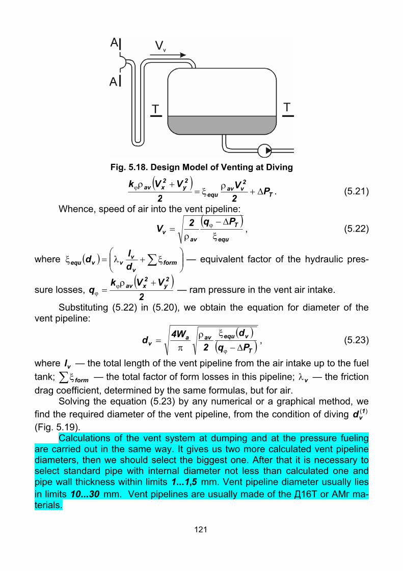
121
Fig. 5.18. Design Model of Venting at Diving
( )
T
2vav
equ
2y
2xav P
2V
2VVk
∆+ρ
ξ=+ρϕ . (5.21)
Whence, speed of air into the vent pipeline:
( )
equ
T
avv
Pq2Vξ∆−
ρ= ϕ , (5.22)
where ( ) ⎟⎟⎠
⎞⎜⎜⎝
⎛ξ+λ=ξ ∑ form
v
vvvequ d
ld — equivalent factor of the hydraulic pres-
sure losses, ( )2
VVkq
2y
2xav +ρ
= ϕϕ — ram pressure in the vent air intake.
Substituting (5.22) in (5.20), we obtain the equation for diameter of the vent pipeline:
( )
( )T
vequavav Pq
d2
W4d∆−
ξρπ
=ϕ
, (5.23)
where vl — the total length of the vent pipeline from the air intake up to the fuel tank; ∑ξform — the total factor of form losses in this pipeline; vλ — the friction drag coefficient, determined by the same formulas, but for air.
Solving the equation (5.23) by any numerical or a graphical method, we find the required diameter of the vent pipeline, from the condition of diving )(1
vd (Fig. 5.19).
Calculations of the vent system at dumping and at the pressure fueling are carried out in the same way. It gives us two more calculated vent pipeline diameters, then we should select the biggest one. After that it is necessary to select standard pipe with internal diameter not less than calculated one and pipe wall thickness within limits 511 ,... mm. Vent pipeline diameter usually lies in limits 3010... mm. Vent pipelines are usually made of the Д16Т or АМг ma-terials.

122
Fig. 5.19. Solving Equation (5.23) by Graphical Method
5.7. Designing the scheme and calculation of fuel dump system Many transport and passenger airplanes are equipped with in flight fuel
dump (jettisoning) system. Dumping of fuel is carried out in the following cases: – Before emergency landing, if by conditions of structural strength there is
a limitation on the maximum landing mass. – If presence of fuel onboard is undesired by fire safety (landing with the
failed landing gear or engine, etc.). – If landing is carried out on runway of insufficient length. The fuel dump system shall provide: 1. Dumping the specified volume of fuel during specified period. The time
of dumping is normalized and according to NLGS-3 depends on volume of the fuel tanks:
t less than 7 minutes VT < 10000 dm3; t less than 12 minutes VT < 20000 dm3; t less than 15 minutes VT < 30000 dm3. According to АП-25 during 15 min at the least favorable conditions, it is
required to dump enough amount fuel to comply climb requirements. 2. Keeping the centre-of-gravity position and controllability within accept-
able limits. 3. Fire safety. I. е. fuel at dumping must not get into the engine or on
other parts of the aircraft. Depending on arrangement of the fuel system, sizes and capacity of fuel
tanks, to provide these requirements, dumping of fuel is designed by gravity, forced out or by pumps.

123
Let's consider calculation of fuel dump system. During time dτ the volume of fuel in the fuel tank is changed by value:
dHFdVF Tdd −=τ , (5.24) where 4dF 2
dd π= — cross–sectional area of the dumping pipeline; dV — speed of fuel into the dumping pipeline; TF — cross–sectional area of the fuel tank by the horizontal plane at H level; H — fuel level into the fuel tank at the time τ, counting from the exit point of the dumping pipeline in atmosphere (Fig. 5.20).
Fig. 5.20. Scheme of Dumping
Experience shows, that for fuel tanks of any shape, it is possible to carry out calculation by average area of the fuel tank:
21
TavT HH
VFF−
=≈,
where 1H and 2H — initial and final levels of fuel in the fuel tank, counting from the exit point of the dumping pipeline in an atmosphere, Fig. 5.21.
To determine the speed of fuel in the dumping pipeline, we write Ber-noulli’s equation for cross–sections A-A and T-T:
IN
2dF
equ
2dF
FH
2TF
FTH P2V
2V0gP
2VgHPP ∆+
ρξ+
ρ+ρ+=
ρ+ρ+∆+
, neglecting the speed of fuel in the fuel tank TV and inertial pressure losses
INP∆ , we obtain:
( )
2V1PgH
2dF
equTFρ
ξ+=∆+ρ;
whence: g
PH1
g2VF
T
equd ρ
∆+
ξ+=
. (5.25) Let's substitute the expression for dumping speed (5.25) in the equation
of volumes (5.24)
dHFd
gPH
1g2F T
F
T
equd −=τ
ρ∆
+ξ+ ,

124
a b
Fig. 5.21. Law of Signs of Fuel Levels
gPHdH
g21
FFd
FT
equ
d
T
ρ∆+
ξ+−=τ
. Integrating the last expression, we find:
∫ ρ∆+
ξ+=τ
1
2
H
H FT
equ
d
T
gPHdH
g21
FF
,
whence ⎥⎦
⎤⎢⎣
⎡ρ∆
+−ρ∆
+ξ+
=τg
PHg
PHg2
1FF2
F
T2
F
T1
equ
d
T
. (5.26) By formula (5.26) it is possible to determine the dumping time at known
diameter of the pipeline (checking calculation) or to select the diameter of the pipeline by the specified dumping time (designing calculation) (Fig. 5.22).
At high fuel dump rate, an air funnel may appear at the dumping connec-tion. It causes increase of the hydraulic pressure losses and increases the dumping time. In such cases the confuser outlet is installed above the dumping connection (Fig. 5.23). This outlet provides smooth variation of the flow cross–section area and prevents hitting of air into the dumping pipeline.
In the consumed fuel tank, the outlet connection of dumping pipeline is expedient to design outstanding inside the fuel tank (ref. Fig. 5.18). It provides the guaranteed fuel reserve for climb from sea level to 3000 m and thereafter for 45 minutes cruise at a speed for maximum range and landing.
5.8. Fueling System There are two ways of fueling: overwing fueling and pressure one. At overwing fueling, the filtered fuel is fed by the flexible hose through
the fuel discharge nozzle directly to the filler neck (Fig. 5.24) from the fueling device. It is arranged on the upper side of the fuel tank. In case of grouping of fuel tanks, fuel can overflow into the other fuel tanks by connecting pipes. The filler necks are designed according to used standards. The fueling time of all fuel tanks should not exceed the specified value (≈ 30 minutes).

125
Fig. 5.22. Determining Dumping Pipeline Diameter Depending
on Specified Dumping Time
Fig. 5.23. Confuser Outlet of Dumping Connection
Each fuel tank filler connection must prevent the entrance of fuel into any part of the airplane other than the tank itself. Each recessed filler connection that can retain any appreciable quantity of fuel must have a drain that dis-charges clear of each part of the airplane.
Each fuel filling point must have a provision for electrically bonding the airplane to ground fuelling equipment.
Overwing fueling has a number of disadvantages. [–] Long fueling time. (The fueling rate in connecting pipelines is low. It is
required to open and close each filler neck, to move the discharge hose, to switch on and off the pump of priming device for filling.).
[–] Necessity of location of ground maintenance personnel near the filler necks arranged usually on the wing. Ladders, step-ladders, long hoses are re-quired for this purpose. These movements lead to damages of paint coating of the wing. In winter these movements on icy wing surface are dangerous for the people.
[–] Fire danger is increased at fuel vaporation.

126
Fig. 5.24. Filler Neck for Overwing Fueling
1 — Skin; 2 — Bush; 3 — Button; 4 — Plug Casing; 5 — Filler Neck Casing; 6 — Locking Washer; 7 — Nut; 8 — Ball; 9 — Valve; 10 — Chain
[–] A moisture and a dust can probably get into the fuel tank through the upper filler necks.
These disadvantages can be removed at pressure fueling. In this case the filtered fuel is fed by the flexible hose to the fueling connection (Fig. 5.25) of the aircraft from the fueling device.
The pressure fueling provides a number of advantages. [+] Low fueling time. [+] The fueling is carried out through one or two fueling connection.
(Therefore such fueling may also be referred to as «single–point pressure fuel-ing»).
[+] To decrease the length of discharge hoses and for maintainability, these fueling connections are arranged in the lower parts of aircraft. Thus peo-ple movement on wings is not needed.
The fueling connections and nozzles of discharge hoses are designed by the international standards.
The sequence of the pressure fueling can be different (serial or joint). Se-rial tank fueling takes more time, than joint. But the serial fueling provides a ca-pability to fill not all fuel tanks with fuel, but only specified.
Thus there are also a number of disadvantages: [–] A high speed of fuel flow within the pipelines (10...75 dm3/s), a big
length of fueling pipelines and presence of special control devices cause in the big hydraulic pressure losses. Hence, the high power of the pumps installed at fueling devices is required.
[–] The fueling pipelines and the control devices are arranged onboard the aircraft and increase its mass.

127
Fig. 5.25. Filler Neck for Single–Point Pressure Fueling:
1 — Adapter Connector; 2 — Casing; 3 — Sealing; 4 — Flange; 5 — Covering; 6 — Handle; 7 — Rod; 8 — Valve; 9 — Grounding Jack [–] The maximum fuel quantity is impossible to be filled by pressure fuel-
ing owing to response of maximum level valves. Therefore devices for overwing fueling are kept onboard the aircraft.
5.9. Structural Components of Fuel System
5.9.1. Fuel Pumps Fuel pumps can have various types of the drive. Electro–powered centrifugal pumps represent monoblock version of the
pump and the electric motor (Fig. 5.26).

128
Fig. 5.26. Electro–Powered Fuel Pump inside Fuel Tank
The direct-current drive provides ease of regulating of the consumption and high reliability.
The alternating-current drive provides high efficiency at power of pumps more than 1.5 kW. Absence of collectors decreases fire danger into strongly rarefied atmosphere at high altitudes at the increased moisture. A dis-advantage of the alternating–current drive is fixed (or stepwise changeable) ro-tational speed.
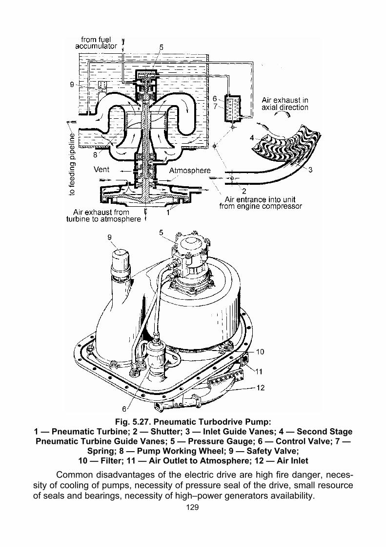
129
Fig. 5.27. Pneumatic Turbodrive Pump:
1 — Pneumatic Turbine; 2 — Shutter; 3 — Inlet Guide Vanes; 4 — Second Stage Pneumatic Turbine Guide Vanes; 5 — Pressure Gauge; 6 — Control Valve; 7 —
Spring; 8 — Pump Working Wheel; 9 — Safety Valve; 10 — Filter; 11 — Air Outlet to Atmosphere; 12 — Air Inlet
Common disadvantages of the electric drive are high fire danger, neces-sity of cooling of pumps, necessity of pressure seal of the drive, small resource of seals and bearings, necessity of high–power generators availability.

130
The pneumatic turbodrive pump is shown in Fig. 5.27. In this case high pressure air supplied by turbojet compressor rotates the turbine, which in it’s turn rotates the wheel of the pump. Such type of the drive has small mass and overall dimensions, high reliability. Disadvantages of pneumatic turbodrive are increase of turbojet specific fuel consumption while the air bleeding from com-pressor. Necessity of the starting electro–powered fuel pump availability, until the turbojet is idle throttle. There is a capability of the turbine racing by centrifu-gal forces during fuel outflow from the pump.
The hydraulic turbodrive pump (Fig. 5.28) is the fuel turbine connected to the pump working wheel (impeller). Feeding of hydraulic turbodrive is carried out by the high–pressure fuel bled after FBP. The hydraulic turbodrive provides the minimal mass and overall dimensions of pump unit. It is not required any seals, as the fuel, rotating the turbine, is mixed up with the fuel, which is pumped up. The hydraulic turbodrive works successfully at the increased tem-peratures. Therefore it is widely used on supersonic aircraft. Starting and stop-ping the hydraulic turbodrive pumps does not impact to their resource. Disad-vantages of the hydraulic turbodrive are big mass of high–pressure fuel pipe-lines, requirements of additional power of FBP for pumping this high–pressure fuel and requirements of starting electro–powered fuel pump availability.
Fig. 5.28. Hydraulic Turbodrive Pump:
1 — Pump Working Wheel; 2 — Turbine Guide Vanes; А — High–Pressure Fuel Inlet; B — Fuel Inlet from Tank; C — Fuel Outlet into Pipeline
5.9.2. Fuel Tanks Fuel tanks should meet the following requirements: – Strength, tightness; – Small mass;

131
– Corrosion stability. Usually the fuel tanks include: 1. Shell; 2. Bulkheads for stiffness (diaphragm); 3. Attachment fittings; 4. Protective self-seal; 5. Fuel tank equipment: 5.1. Filler neck; 5.2. Outlet connection; 5.3. Recuperators (in consumed fuel tank); 5.4. Vent or pressurization line connection ; 5.5. Drain valve (Fig. 5.29); 5.6. Dumping connection; 5.7. Fuel quantity gauges; 5.8. Pumps; 5.9. Electrical bonding. The diaphragms are intended to: – maintain strength and stiffness of the fuel tanks; – soften the hydraulic shocks during changes of aircraft attitude; – quiet the surface of fuel, that reduces vaporation. The outlet connection is usually arranged at some distance from the fuel
tank bottom. It prevents hitting of condensate into the engine. If the fuel tank is flat, the outlet connection is placed sideways, Fig. 5.30.
Fig. 5.29. Drain Valve: 1 — Casing; 2 — Cover; 3 — Rod; 4 — Valve; 5 — Sealing; 6 — Bottom Wing
Skin
Fig. 5.30. Versions of Arrangement of Outlet Connection
To provide a reliable feeding of the engine with fuel during changes of aircraft attitude, sometimes two outlet connections are installed or special recu-perators are applied. In the simplest case, such recuperator is a consumed section of consumed fuel tank equipped with a set of check valves, Fig. 5.31. Such type of recuperator is used at non–maneuverable aircraft. At acrobatic

132
maneuverable airplanes, whole consumed fuel tank can be made as a recu-perator, Fig. 5.32.
Fig. 5.31. Check Valves in Consumed Section Ribs
Fig. 5.32. Consumed Fuel Tank of Ac-robatic Airplane: 1 — Fuel Usage
Pipeline; 2 — Venting; 3 — Fuel Inlet; 4 — Drain Valve
At combat maneuverable aircraft, fuel pumps with recuperators (Fig. 5.33) and fuel accumulators (Fig. 5.34) are usually used.
Fuel tanks can be: internal (stiffen, flexible, integral) and external (under–wing, ventral, laid on and conformal). Internal fuel tanks can be placed into a fuselage or engine nacelles, a wing or a fin.
Fuselage fuel tanks: [+] have the shape convenient for fuel use; [+] have smaller mass, in comparison with wing fuel tanks (because of
strength); [–] take a payload volume in the fuselage. Wing fuel tanks: [+] unload the wing in flight; [+] free payload volume in the fuselage from fuel; [–] complicate fuel use (because the fuel tank is flat); [–] have the bigger surface area subjected to damage. Rigid fuel tanks: [+] have the stiffness independent of the airframe; [–] require big cut–outs to install and remove them from airplanes; [–] do not completely use the allowable volume of the airframe; [–] can be damaged by vibrations; [–] have big mass.

133
Fig. 5.33. Fuel Pump with Recuperator:
1 — BPA; 2 — Drain Valve; 3 — Valve Level; 4 — Weight;
5 — Base Plate; 6 — Valve Casing; 7 — Weight Axis of Rotating;
8 — Carrier; 9 — Valve
Fig. 5.34. Fuel Accumulator: 1 — Flange; 2 — Pipeline Returning
Fuel to Pump; 3 — Fuel Pipeline; 4 — Pressurization Pipeline;
5 — Shape; 6 — Diaphragm; 7 — Air Shell; 8 — Sealing; 9 — Bolt;
10 — Fuel Shell Now they are applied on light airplanes with piston engines. The rigid fuel tanks are made of sheets of aluminium alloys such as АМг
and АМц. These alloys allow deep draw–forming, embossings, they are corro-sion–resistant and well welded. Recently composite materials are also used for manufacturing stiffen fuel tanks.
By its design, the cover of rigid fuel tanks usually consists of a shell and two welded bottoms (Fig. 5.35). Welding provides tight connection. The fuel tank is welded from outside on special flanging separated by embossings. It eliminates hitting of a flux and a fire scale inside of the fuel tank and reduces residual stresses after welding.
Bulkheads are usually produced of duralumin. As duralumin is bad welded, bulkheads are attached to the shell with rivets. The head of rivets sometimes are welded for tightness.
Installation of stiffen fuel tank is usually carried out with special support assemblies, to which fuel tank is held down with attaching straps (Fig. 5.36).
After manufacturing, all fuel tanks are tested for tightness and vibration strength.
On military airplanes, the fuel tanks are usually covered with a self–seal which is capable to tighten shell–holes in the fuel tank.
Flexible fuel tanks (Fig. 5.37): [+] are installed and removed through cut-outs of small sizes and thus less

134
weaken an assembly, in which they are installed; [+] are stable to vibrations; [+] have good survivability; [+] have mass smaller, than rigid ones;
Fig. 5.35. Design of Rigid Fuel Tanks:
1 — Bottom; 2 — Shell; 3 — Bulkhead; 4 — Fuel Outlet; 5 — Drain Valve; 6 — Fuel Tank Equipment Pipeline Connections
Fig. 5.36. Installation of Rigid Fuel Tank with Attaching Straps:
1 — Attaching Strap; 2 — Tank; 3 — Bulkheads; 4 — Support Assemblies; 5 — Felt Plate; 6 — Tender; 7 — Bolt, Attaching Strap with Rib Node
[–] lose elasticity at low and high temperatures, hence appearance of cracks is possible;

135
[–] have mass greater than integral fuel tanks; [–] require presence of container inside the airframe; [–] are subject to dissolution in fuel, hence periodic flushing is required.
Fig. 5.37. Flexible Fuel Tank:
1 — Bushing of Vent Connection; 2 — Lock Attaching Tank to Bracket; 3 — Container; 4 — Sensor of Fuel Quantity Gauge; 5 — Fuel Transfer Pipeline from
Other Tank; 6 — Vent Hole; 7 — Tank; 8 — Booster Pumps; 9 — Knob; 10 — Retaining Screw; 11 — Catch; 12 — Casing of Lock;
13 — Metal Cone; 14 — Locking Washer; 15 — Loop; 16 — External Layer of Tank; 17 — Internal Layer of Tank; 18 — Glue Layer; 19 — Internal Strap; 20 —
External Strap; 21 — Plate Attaching Pumps; 22 — Drain Valve; 23 — Hold–Down; 24 — Check Valve; 25, 26 — Bushes
The cover of flexible fuel tanks usually consists of several layers. Inside there is a layer of fuel resistant rubber. The following layer is usually the self–seal, tightening shell–holes. Then there is a layer of vulcanized rubber. The ex-ternal layer is the protective cord (strong rubber cloth).
The fuel tank equipment is vulcanized to walls of the fuel tank, and be-sides, is fastened to the container.
Integral fuel tanks represent the closed pressurized section of an air-frame. Integral fuel tanks:
[+] use the allowable volume completely; [+] have minimal mass; [+] do not require big cut–outs for maintenance; [–] are subjected to aerodynamic, vibrational, thermal effects;

136
[–] require special measures to provide full fuel use; [–] require tightening. Tightening process is complicated, detrimental to
health, not always reliable. Now the fasteners with the radial interference, ensuring tightness without
hermetic, obtained a wide application. For example, when riveting by usual riv-ets, radial interference appears in snap rivet head zone only (Fig. 5.38, a). While riveting by rivets with compensator, radial interference generates practi-cally along whole pack thickness (Fig. 5.38, b). The very radial interference gives tightness of riveted joint. Such fasteners reduce labouriousness, reduce assemblies production time, allow to reduce using of harmful hermetic in manu-facture, decrease mass.
a b
Fig. 5.38. Using Fasteners with Radial Interference External (under–wing, ventral, laid on and conformal) fuel tanks rep-
resent rigid fuel tanks, extruded directly to a ram airflow. Just like the integral fuel tank, it is subject to aerodynamic, vibrational, thermal effects. Besides, the shape of such fuel tanks should provide the minimal external drag at the speci-fied volume. The shape of fuel tanks should not cause stalls, disturbance of stability and controllability of the aircraft.
On manoeuvrable airplanes external fuel tanks are usually designed droppable (Fig. 5.39). It allows to get rid fast from superfluous mass and to im-prove a manoeuvrability of the airplane if necessary. As a result there are no pumps inside them. As the fuel pump is very expensive. Therefore fuel feeding from external fuel tanks is usually provided by forcing out. Thus the tanks pres-surization with overpressure increases strength of fuel tanks.
Laid on fuel tanks differ from under–wing or ventral only in arrangement. And they are usually not droppable. Conformal fuel tanks represent external fuel tanks, attached to the airplane without clearances. Thus total aerodynamic drag of the system (the airplane plus the fuel tank) can even be decreased. The external weapon–pylon bases can be attached to such conformal fuel tank, Fig. 5.40.

137
Fig. 5.39. Ventral Fuel Tank:
1 — Ventral Tank; 2 — Pylon for Attaching Tank; 3 — Fuel Outlet Connection; 4 — Forward Stop; 5 — Bush of Pyropusher; 6 — Eyebolt; 7 — Pressurization Connection; 8 — Rear Stop; 9 — Pressurized Bulkhead; 10 — Check Valve;
11 — Filler Neck; 12 — Drain Valve of Forward Section with Filter; 13 — Drain Valve of Rear Section; 14 — Filler for Fuel Pumpdown on Ground
Fig. 5.40. Conformal Fuel Tank of F-15 Airplane
Checklist 1. What is fuel system?

138
2. List main requirements to fuel system. 3. What is a fuel for aviation engines? 4. What are heat of combustion and volumetric heat of combustion?
What are the units to measure these values? 5. How does fuel density change with temperature increase? To what
does it lead on aircraft? 6. What is fuel saturated vapor pressure? How is it designated and why? 7. How does fuel saturated vapor pressure change with temperature in-
crease? 8. What are coefficients of dynamic and kinematic viscosity? What are
the units to measure these values? 9. How does coefficient of fuel kinematic viscosity change with tempera-
ture increase? 10. To what does water and mechanical impurities presence in fuel lead?
How to avoid it? 11. How are aviation fuels marked? Give examples. 12. Describe fuel system structure. 13. Name and characterize three ways of fuel feeding. 14. What is double-stage fuel boost? Why is it so widely used? 15. What are the functions of check valve in fuel pipelines? 16. What are the functions of fuel accumulator? 17. Why is fuel-oil cooler arranged before filter, but not vise versa? 18. What elements of test and measurement equipment are installed in
fuel feed pipeline? 19. List advantages and disadvantages of parallel and serial connection of
fuel tanks in groups. 20. Characterize schemes of fuel feeding to engines. 21. What are structural solutions used to increase reliability of fuel feed to
engines? 22. What kinds of calculations are made while fuel system designing? 23. What is the content of required capacity of fuel tank? 24. Where is fuel usually arranged onboard modern airplanes? 25. What is fuel system altitude performance? 26. What determines fuel system altitude performance? 27. Write fuel system altitude performance condition. 28. What is cavitation margin? 29. What information should be available to make altitude performance
calculation? 30. List operation conditions for fuel system altitude performance calcula-
tion. 31. What equations are initial to make fuel system calculation? 32. What is overpressure in the fuel tank? How is it created? 33. What kinds of total pressure losses do you know?

139
34. How is Reynolds’ number defined for pipeline of circular cross-section? What does it characterize?
35. What parameters are determined while fuel system designing calcula-tion?
36. What ways are used to increase fuel system altitude performance? 37. What is the purpose of venting and pressurization of fuel system? 38. What schemes of venting do you know? 39. Where is usually vent tank arranged? 40. What can be a source of gas at closed vent system? 41. What is the purpose of reduction valve of vent system? 42. List critical load conditions for vent system. 43. In what cases is fuel dump (jettisoning) system used? 44. What ways of fueling do you know? 45. List advantages, disadvantages and areas of application of pressure
fueling. 46. List types of fuel pumps drives. Give brief description for each of
them. 47. List members of fuel tank. 48. What is the purpose of diaphragms inside fuel tank? 49. What types of fuel tanks do you know? 50. Why is outlet connection in fuel tank usually arranged at some dis-
tance from the fuel tank bottom? 51. What are the structural solutions used in consumed tanks to provide a
reliable fuel feed to engine? 52. List advantages and disadvantages of fuselage and wing fuel tanks. 53. List advantages, disadvantages and areas of application for rigid fuel
tanks. 54. In what way are rigid fuel tanks attached to airframe? 55. List advantages, disadvantages and areas of application for flexible
fuel tanks. 56. What layers does usually flexible fuel tank shell consist from? 57. In what way are flexible fuel tanks attached to airframe? 58. List advantages, disadvantages and areas of application for integral tanks. 59. List features of external fuel tanks. 60. What way of fuel feeding is used in external fuel tanks?

140
Theme 6. LUBRICATION SYSTEMS OF POWER PLANTS
6.1. Purpose of Lubrication Systems and Requirements A lubrication system represents a set of units intended for lubrication of
the engine, heat rejection from engine units, and also the removal of solid parti-cles, which are formed between surfaces subjected to friction, in all aircraft op-erating conditions.
Even short–term breaks in oil feeding result in the engine overheating, destruction of its bearings, wedging of pistons, or a rotor, breakage of connect-ing rods and, as a result, the engine failure.
In power plants, oil is also used as hydraulic liquid in various devices (such as a propeller pitch control mechanism, fuel control units, rpm governor, etc.).
The lubrication system consists of two sections: external and internal. The external section is a component of the aircraft power plant. The internal section is a component of the engine. In our course we shall consider only the external section of lubrication system.
Requirements to lubrication systems Reliable oil supply to the engine at the temperature and pressure due to
specifications, in any aircraft operation conditions. Minimum power consumption during heated oil cooling process. Reliable oil filtering from mechanical impurities and gases. Fast oil heating, to reduce the heating–up time of the engine. Preventing oil ejection through venting and overflow of the engine at all
engine settings. Preventing oil overflows from the tank into the inoperative engine. Minimal mass of the system. The sufficient strength, vibration strength, leak resistance, and minimal
hydraulic pressure losses of the system elements. Fire safety. Maintainability (convenient access to the lubrication system for mainte-
nance and repair). On multi–engine aircraft, each engine should have an independent lubri-
cation system. Pipelines and units of lubrication systems should be of brown color.
6.2. Aviation Oils For the reliable and continuous operation of a lubrication system, oil
properties are very important. Operating conditions for oils in engines are com-plicated and various, therefore oil specifications are characterized by strict re-quirements to their physical and chemical properties.

141
Viscosity is one of the major properties of oil. If oil viscosity is insufficient, the liquid layer of the oil cannot stay in clearances and is extruded at heavy loadings. As a result, dry friction emerges, which increases the wear of parts.
If oil viscosity is too high, then: – friction forces increase, which causes power losses; – oil does not get to units with small clearances; – increased pressure in lubrication system is required for pumping oil; – engine start-up is complicated. The value of oil viscosity is measured by the factors of viscosity. Just as
with fuel, there are two factors of oil viscosity: kinematic and dynamic ones. The factor of kinematic viscosity of aviation oils is in the range:
2552 ....=ν mm2/s. The viscosity of oil drops with the increase of temperature. In the past,
most aviation oils were made from petroleum, by acid (МК) or selective (МС) clearing. The viscosity of such oils drops sharply with increase in temperature. High temperature in lubrication system results in the active vaporation and oxi-dation of these oils. The resulting deterioration of their physical and chemical properties, worsens the lubrication system operation. Now, in heat–stressed engines, synthetic oils are widely used. They are formed on the basis of esters. The viscosity–temperature relation for such oils is weaker. Besides, these oils have a broad range of operation temperatures.
The density of aviation oils makes 950850...=ρ kg/m3. The thermal–oxidative durability of oil is characterized by maximum tem-
perature at which the oil can be used. When this temperature is exceeded oil is coked, i.e. oil sediment appears, and a film is formed on the greased parts. The type of oil to be used is determined by the type of the engine.
6.3. General Characteristics of Lubrication Systems
6.3.1. Lubrication Systems for Piston Engines Lubrication systems for piston engines are the most complicated and
loaded ones. Piston engines have a big friction area. There is high pressure ( 25≥ МPа) on these surfaces, which increases the heat transfer into oil (Q = 3400...6800 J/(kw⋅min)). Hence, big oil flow rate through the engine (2.7...5.4 dm3/(hour⋅kw)) is required.
Second feature of lubrication system of piston engines is that, oil directly contacts with a combustion zone, that causes high oil consumption (CP = 8...16 g/(hour⋅kw)).
To provide lubrication system operation in these conditions, oils with vis-cosity 20...25 sSt at 100°C are required, for example МС–20, МК–22 (the num-ber in the marking designates viscosity in sSt at 100°С). In winter conditions less viscous oils are applied.

142
The recommended oil temperature makes 65...75°C at the input connec-tion of an engine, and 105...125°C at the output connection. Delivery oil pres-sure is in the range of 0.5...0.8 МPа.
6.3.2. Lubrication Systems of (Bypass) Turbojets The principal type of friction in these engines is rolling friction, therefore,
the power consumption required to overcome the friction forces and the amount of the transferring heat are insignificant (85...170 J/(daN⋅min)). Oil flow through the engine makes 3...5 dm3/min per bearing. The oil consumption basically comes from the losses through the breather system and makes ≈1 g/(daN⋅hour).
Under these conditions oils with low viscosity (МК–6, МК–8, and also syn-thetic oils) are applied.
The allowable input oil temperature makes 25...80°C, and the output 100...130°C. The oil delivery pressure for turbojets is in the range 0.1...0.4 МPа.
6.3.3. Lubrication Systems of Turboprops Due to the complexity and the loadings of the turboprops lubrication sys-
tems, they are intermediate between the lubrication systems of piston engines and turbojets. The difference between these systems consists in employing the propeller gear to transmit the high power. The pinions of this propeller gear re-quire, thus, flood lubrication.
The turboprop heat–to–oil transfer (680...1400 J/(kw⋅min)) is higher, than turbojets’, but is lower than piston engines’. So, the oil flow (0.65...0.98 dm3/(kw⋅hour)) is intermediate too.
It is not desirable to apply here oils with high viscosity, since the rate of the propeller blade angle change drops, and engine start–up is complicated. A mixture of oils with high and low viscosity (e. g. 75 % of МС-20 and 25 % of МК-8) is usually used to lubricate turboprops.
6.4. Lubrication System Schemes. Methods of Separation Air from Oil
There are two types of lubrication systems: closed (circulating) and open, the latter is applied to the products of single utilization. The closed type sys-tems are used in aviation.
Direct Scheme of Lubrication System The simplest scheme of lubrication system is the direct scheme (Fig. 6.1).
In this case oil circulates through the following path: oil tank – engine –cooler – oil tank.

143
Fig. 6.1. Direct Scheme of Lubrication System
1 — Engine; 2 — Manometer; 3 — Pressure Pump; 4 — Thermometer of Oil at Engine Inlet; 5 — Suction Pipeline; 6 — Shut–Off Valve; 7 — Venting;
8 — Oil Tank; 9 — Scavenge Pipeline; 10 — By–Pass Valve; 11 — Cooler; 12 — Filter; 13 — Drain Valve; 14 — Thermometer of Oil at Engine Outlet; 15 — Scav-
enge Pump The section of lubrication system from oil pressure pump to scavenge
pump (including them) is an internal pipeline of the engine 1. The external lu-brication system includes: oil tank 8, cooler 11, suction (tank – engine) 5 and scavenge (engine – cooler – tank) 9, pipeline sections, venting pipeline 7, drain pipes and valves 13, instruments for measurement of pressure 2 and tempera-ture 4, 14 of oil and oil meter.
The suction pipeline should be straight, short and have a large diameter. To improve operating conditions of the pressure pump 3, it is possible to install the oil tank above the pump.
The shut–off valve 6 is sometimes installed in the suction section, to pre-vent the oil overflow from the tank into the inoperative engine through the switched off pump. In this case it is necessary to interconnect this valve with the engine starting system.
For protection of lubrication system against chips, calx, dust and flux coming from the oil tank, it would be expedient to install the filter in the «tank – engine» pipeline section. But thus there will be a high pressure losses in the suction pipeline. Thus altitude performance of lubrication system will decrease. Therefore filters 12 are installed in the scavenge section. If metal chips emerge on the filter surface, that is the first indicator of violation of normal engine op-eration. Additional filter grids are installed in the filler necks and in the tank out-let connections.
To prevent the oil and its emulsion from accumulation in the engine cas-ing, the scavenge pumps 15 should have 2...3 times more volume flow, than

144
pressure pumps have. As the pumps except for the emulsion, pump out big quantity of air, it results in additional saturation of oil by air.
The cooler 11 is equipped with the by–pass valve 10, intended to prevent the cooler core rupture at low oil temperatures and provide the fast oil heating–up. As at the open valve, oil circulates, omitting the core. When oil is heated and the pressure drops, the valve closes and brings the cooler into operation.
The spring–loaded valves (Fig. 6.2, а) are the simplest in design and the most reliable. Their essential disadvantages consist in the capability of passing of cold oil through the cooler at the low engine power. Thus oil flow is small and resistance of cooler is small too. It increases heating–up time of oil, and in flight (for example, at gliding) causes its super–cooling. It can cause the oil solidifica-tion and breaking of oil flow.
a b Fig. 6.2. Schemes of By–pass Valves
For this reason, the thermostatic valves (Fig. 6.2, b) are preferable. Such valves react to the oil temperature variation due to the silphon filled with low–boiling fluid. With heating of oil, the silphon extends, and the valve closes. Thus oil will flow only through cooler core.
It is necessary to note the difference between the purpose of the fuel tank and oil tank venting systems. In fuel tanks, the air feed is required to provide specified overpressure in the fuel tank. In oil tanks, the air discharge is re-quired, because of the air comes in plenty from the engine together with air–oil emulsion.
It is recommended to direct venting connections of oil tank downwards in order to prevent the oil accumulation, solidification in them and, as a result, breaking of the oil tank. For the same reason, venting should be directed to a warm place, such as a cooler tunnel situated behind the oil cooler.

145
Venting of lubrication system can be open and closed (through a breather system).
When designing the lubrication system, it is necessary to provide full, fast and reliable drain of oil from the oil tank, cooler, filter sediment trap and pipe-lines. Convenient access to drain valves should be provided. It is necessary to prevent hot oil from hitting onto hands of ground maintenance personnel, elec-trical wiring, exhaust pipes, and wheel tyres.
Operation of lubrication system is inspected by oil pressure and tempera-ture at engine inlet and by oil meter.
Air–from–Oil Separation When passing through the engine, the oil is saturated with air, gases and,
in piston engines, with fuel vapors. During lubrication of various units, bubbles of air are in addition shattered. As a result, the air–oil emulsion is formed, this emulsion is pumped out by scavenge pumps. Thus there is additional oil satu-ration by air. Behind the cooler, pressure of oil drops, and additional air educes from it. Thus oil, in which there are bubbles of various sizes, gets in the oil tank. Size of these bubbles changes from molecular up to 10...20 mm in diameter.
Large bubbles rapidly float and separate from oil. The less sizes of bub-bles, the less its speed of float, and it is more difficult to separate them from oil.
The floating speed is directly proportional to the squared float diameter and inversely proportional to the oil viscosity. Thus, the more time the oil in the tank is available, the less air comes to suction pipeline. The higher the oil tem-perature and the lower the oil viscosity becomes, the less time it takes for the bubble to get the surface ( )tDV 2
y µ~ . The following measures are assumed to reduce the contents of air in oil: Reducing hydraulic pressure losses in scavenge pipeline of oil. Minimally required difference between oil flows of scavenge and pressure
pumps should be chosen. Installation of special de–aerators in the oil tank. They use a principle of
coagulation — enlargement of gas particles in two-phase medium. Centrifugal de–aerators have the wide application now. They provide the
complete air–from–oil separation, and better altitude performance of lubrication system; however they require a lot of power.
Let’s note the disadvantages of the direct scheme of lubrication system: [–] High back pressure, owing to presence of the cooler in a scavenge
pipeline; [–] Low temperature in the oil tank; causing the high oil viscosity and the
low speed of the air bubbles floating. [–] Altitude performance of the direct scheme lubrication system makes
7...8 km. Owing to these disadvantages, other schemes of lubrication system are
widely used.

146
Reverse Scheme of Lubrication System The oil circulates according to the scheme (Fig. 6.3): oil tank 11 –
cooler 5 – engine 1 – oil tank.
Fig. 6.3. Reverse Scheme of Lubrication System
1 — Engine; 2 — Manometer; 3 — Pressure Pump; 4 — Thermometer of Oil at Engine Inlet; 5 — Cooler; 6 — By–Pass Valve; 7 — Suction Pipeline;
8 — Filter; 9 — Transfer Pump; 10 — Venting; 11 — Oil Tank; 12 — Scavenge Pipeline; 13 — Scavenge Pump
Hot oil, without cooling in the cooler, gets directly to the oil tank. The oil viscosity considerably decreases. The speed of air separation proportionally in-creases. Besides, through absents of cooler, the air bubbles are not shattered and keep the relatively big diameter; that also promotes fast air separation.
When the oil cleared from air flows through the cooler, its heat rejection increases. Since the oil from the cooler passes directly to the pressure pump, the system reacts faster to the regulating of cooling.
But the pressure pump cannot provide the oil pumping through the cooler. Therefore, the additional pump 9 in the segment «oil tank – cooler –engine» should be installed in the reverse scheme of lubrication system. It is a disad-vantage of the reverse scheme.
The altitude performance of the reverse scheme lubrication system makes 10...12 km.
Single-Circuit Scheme with Centrifugal De-aerator The altitude performance of the direct scheme can be increased by the
installation of the centrifugal de–aerator 9 in the oil scavenge pipeline (Fig. 6.4).

147
Fig. 6.4. Scheme of Lubrication System with Centrifugal De–aerator 1 — Engine; 2 — Pressure Pump; 3 — Suction Pipeline; 4 — Venting;
5 — Oil Tank; 6 — By–Pass Valve; 7 — Scavenge Pipeline; 8 — Cooler; 9 — Centrifugal De–Aerator; 10 — Scavenge Pump
The centrifugal de–aerator (Fig. 6.5) is installed before the cooler, thus making the process of air separation far easier (as the oil is hot). Besides heat rejection in the cooler also increases, as oil is cleared from air.
This scheme is the most used on up-to-date turbojet airplanes (Yak-40, Il-96, Tu-154, An-74, An-148, An-124).
Fig. 6.5. Centrifugal De–aerator
1 — Casing; 2 — Impeller; 3 — Oil Exit Pipeline Connection; А and В — Annular Cavities

148
Shorted Schemes As the centrifugal de–aerator is capable to clear the oil from air, there is
no need for oil circulation through the oil tank. This fact has resulted in the de-velopment of the shorted lubrication system (Fig. 6.6, 6.7).
Fig. 6.6. Shorted Scheme Lubrication System with Ejector
1 — Engine; 2 — Pressure Pump; 3 — Suction Pipeline; 4 — Venting; 5 — Ejector; 6 — Oil Tank; 7 — By–Pass Valve; 8 — Scavenge Pipeline;
9 — Cooler; 10 — Centrifugal De–Aerator; 11 — Scavenge Pump
Fig. 6.7. Shorted Scheme Lubrication System with Pump
1 — Engine; 2 — Pressure Pump; 3 — Suction Pipeline; 4 — Check Valve; 5 — Transfer Pump; 6 — Venting; 7 — Oil Tank; 8 — By–Pass Valve;
9 — Scavenge Pipeline; 10 — Cooler; 11 — Centrifugal De–Aerator; 12 — Scavenge Pump
According to this scheme the oil circulates within the contour «engine – scavenge pump 11 – de–aerator 10 – cooler 9 – pressure pump 2 – engine».

149
The ejector 5 serves for compensation of the oil consumption only. The scheme provides. [+] Fast oil preheating (as only the oil circulating within the contour is pre-
heated). [+] Good altitude performance (due to the capability of creation of backup
in the main pump inlet, Fig. 6.7). [+] Small capacity (hence mass) of the oil tank. The oil tank contains only
the store of oil consumed in flight. [–] As the tank is not used for cooling oil, the cooling surface of the cooler
(hence mass) should be increased. The shorted schemes of lubrication system are used on short– and me-
dium range turboprop airplanes (An-10, An-24). Double-Circuit Scheme of Lubrication System
Double–circuit scheme of lubrication system (Fig. 6.8) has the boost pump 5 and two contours of oil flow: main and additional.
The main contour includes: pressure pump 2 – engine – scavenge pump 13 – centrifugal de–aerator 12 – cooler 11 – pressure pump. Approxi-mately 90% of oil circulates in this contour. The residual oil passes in the oil tank for preheating through the additional circuit (cooler – oil tank 7 – boost pump). The diameter of bleed 8 in the additional circuit is selected by condition of passing of the oil optimal quantity (approximately 10%) through it.
The double–circuit scheme has the same advantages as the shorted scheme. It is applied in power plants of long–range airplanes, such as Il-18, Il-62, Il-86.
Fig. 6.8. Double–Circuit Scheme Lubrication System
1 — Engine; 2 — Pressure Pump; 3 — Suction Pipeline; 4 — Check Valve; 5 — Transfer Pump; 6 — Venting; 7 — Oil Tank; 8 — Bleed; 9 — By–Pass Valve; 10 — Scavenge Pipeline; 11 — Cooler; 12 — Centrifugal De–Aerator; 13 —
Scavenge Pump

150
6.5. Calculation of Lubrication System
6.5.1. Calculation of Required Capacity of Oil Tank The oil tank capacity is calculated by condition of filling up the tank with
maximum amount of oil and providing the reserve volume for the oil expansion and foam.
The oil tank capacity is calculated as a sum of the following volumes: 1) The volume 1V required for consumed oil capacity
M
eM1
NCKVρ
τ⋅⋅= ,
where MC — specific oil consumption; eN — engine power; τ — maximum possible engine operation time without oil servicing; Mρ — oil density; K — safety factor, which takes into account random oil emission, incomplete filling up, etc 21151K .....≈ .
2) The volume 2V that is the amount of oil left in the oil tank at the end of flight. This volume provides the acceleration of the system (to provide normal oil temperature at advance the throttle control lever, and in case of the delay in opening the cooler shutters) the lubrication in case of oil outflow in the casing, etc.
( ) ( )105100N52V e
2 ...... +≈ [L].
Value 2V is usually specified by the engine manufacturer and is specified in maintenance manual.
3) The volume 3V required for a lubrication system filling up. Thus, the oil capacity, which is filled in the system is determined as
321LS VVVV ++= . The total oil tank capacity is LS1T VKV ⋅= , where 1K — the tank capacity
safety factor at the oil–into–foam expansion 251151K1 .....= .
6.5.2. Calculation of Altitude Performance of Lubrication System Altitude performance of lubrication system is the maximum flight altitude
up to which the pressure pump provides the required oil flow at minimal allow-able pressure.
Diameter of suction pipeline is determined as a result of the calculation. Parameters of the pressure pump, the maximum pressure valve in the tank, etc. are also checked. The scavenge line usually is not calculated. Diameter of the scavenge pipeline is assumed equal to ( ) PS d180d ....= .
Condition of lubrication system calculation is the required oil flow through the engine. Oil pressure in the pressure pump inlet is accordingly determined.
Calculation of oil pressure in the pressure pump inlet is carrying out simi-larly to the calculation of fuel system
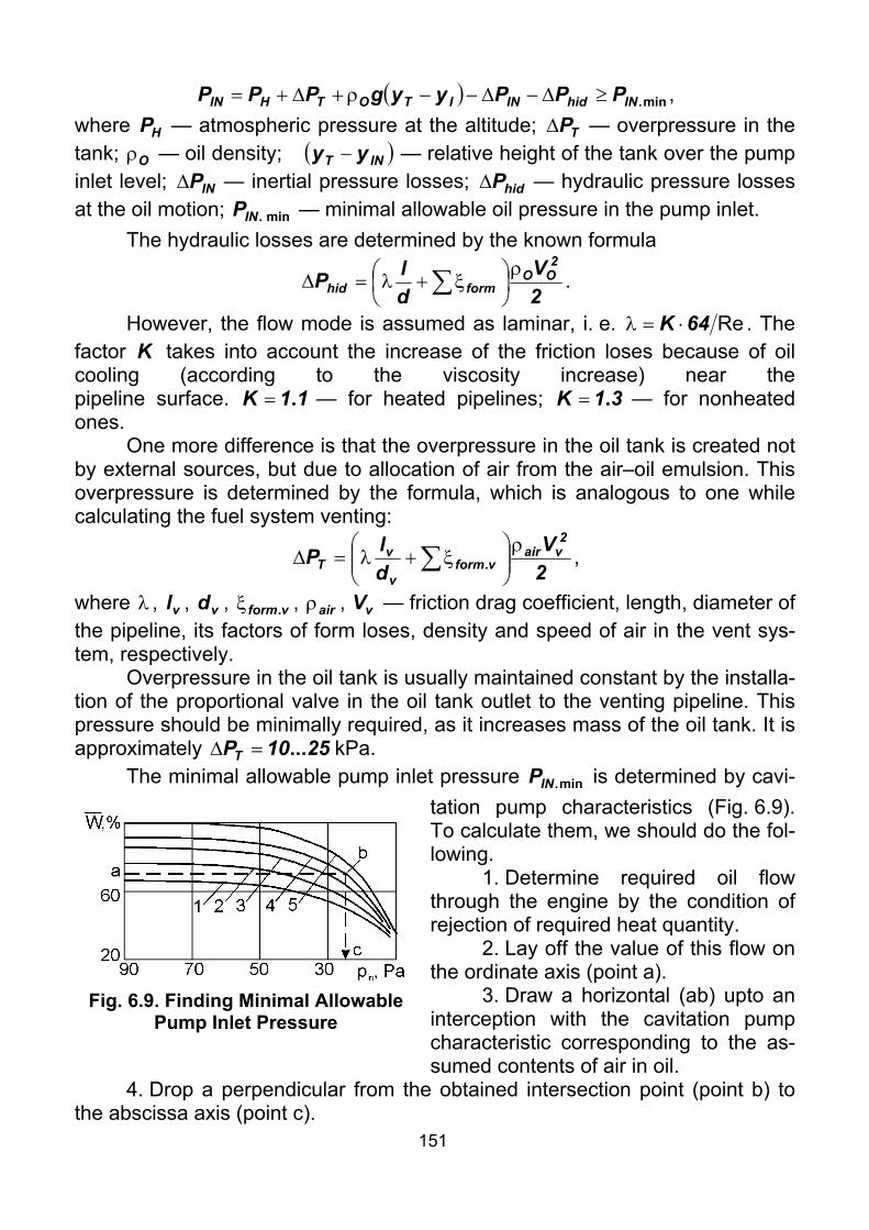
151
( ) min.INhidINITOTHIN PPPyygPPP ≥∆−∆−−ρ+∆+= , where HP — atmospheric pressure at the altitude; TP∆ — overpressure in the tank; Oρ — oil density; ( )INT yy − — relative height of the tank over the pump inlet level; INP∆ — inertial pressure losses; hidP∆ — hydraulic pressure losses at the oil motion; min.INP — minimal allowable oil pressure in the pump inlet.
The hydraulic losses are determined by the known formula
2V
dlP
2OO
formhidρ
⎟⎠⎞
⎜⎝⎛ ξ+λ=∆ ∑ .
However, the flow mode is assumed as laminar, i. e. Re64K ⋅=λ . The factor K takes into account the increase of the friction loses because of oil cooling (according to the viscosity increase) near the pipeline surface. 11K .= — for heated pipelines; 31K .= — for nonheated ones.
One more difference is that the overpressure in the oil tank is created not by external sources, but due to allocation of air from the air–oil emulsion. This overpressure is determined by the formula, which is analogous to one while calculating the fuel system venting:
2V
dlP
2vair
vformv
vT
ρ⎟⎟⎠
⎞⎜⎜⎝
⎛ξ+λ=∆ ∑ . ,
where λ , vl , vd , vform.ξ , airρ , vV — friction drag coefficient, length, diameter of the pipeline, its factors of form loses, density and speed of air in the vent sys-tem, respectively.
Overpressure in the oil tank is usually maintained constant by the installa-tion of the proportional valve in the oil tank outlet to the venting pipeline. This pressure should be minimally required, as it increases mass of the oil tank. It is approximately 2510PT ...=∆ kPa.
The minimal allowable pump inlet pressure min.INP is determined by cavi-tation pump characteristics (Fig. 6.9). To calculate them, we should do the fol-lowing.
1. Determine required oil flow through the engine by the condition of rejection of required heat quantity.
2. Lay off the value of this flow on the ordinate axis (point а).
3. Draw a horizontal (ab) upto an interception with the cavitation pump characteristic corresponding to the as-sumed contents of air in oil.
4. Drop a perpendicular from the obtained intersection point (point b) to the abscissa axis (point c).
Fig. 6.9. Finding Minimal Allowable Pump Inlet Pressure

152
If altitude performance of the lubrication system is not provided, the fol-lowing measures can be used: increase of overpressure in the oil tank, the booster pump installation, the increase of pipeline diameter or use of another lubrication system scheme.
6.6. Oil Cooling. Coolers Coolers are devices intended for transferring heat from the cooled me-
dium to the cooling one. Coolers are named by the medium: cooling–cooled: air–oil, fuel–oil, water–oil coolers.
Air–oil coolers are usually applied on airplanes with piston or turboprop engines. In this case, fuel–oil coolers are not used, as far as the heat flow into oil is considerable, but fuel consumption is low. Thus fuel can not cool oil down to acceptable temperature.
Fuel–oil coolers are usually used on airplanes with (bypass) turbojets. It provides:
[+] Elimination of power consumption intended for overcoming the exter-nal drag of the cooler installation;
[+] Preheating of fuel before supplying it to the engine; [+] Automatic regulation of oil temperature while changing the engine
power, i.e. the fuel consumption. Besides on supersonic airplanes, the air stagnation temperature can ex-
ceed the oil temperature, thus, preventing the cooling process. Therefore for such airplanes fuel–oil coolers will be used only.
According to the design we can distinguish two types of coolers: honey-comb and finned.
Honeycomb coolers (Fig. 6.10) consist of a set of copper or brass pipes of 250...300 mm long, with the wall thickness of 0.1...0.2 mm and the 4...5 mm in diameter, concluded in a steel casing.
The pipe tails at the ( )d32l ...= segment are flared to a hexahedron and hermetically soldered. Thus there are slots among the pipes, through which the hot oil passes. The cooling medium flows inside the pipes. To increase the oil path and to decrease the cooler sizes, bulkheads are installed in the cooler. Besides, these bulkheads provide strength and stiffness of the cooler structure.
The honeycomb coolers are convenient in service. In case of tube leak-age, it is possible to unsolder it and replace or solder both ends.
The shape of coolers is selected in compliance with arrangement on the airplane: round, oval, horse-shoe.
The other type of coolers is finned coolers (Fig. 6.11). They consist of a set of streamlined pipes, made of aluminum alloys and welded to the perforated plates. The oil flows inside these pipes, and the air passes in the space among the pipes.
Finned coolers have approximately 25% smaller mass, they are stronger than honeycomb ones. Their tightness does not depend on quality of welding.

153
The finned coolers have stable heat conduction characteristics. Their only dis-advantage is that it is impossible to repair a finned cooler in field conditions.
Fig. 6.10. Design of Honeycomb Air–Oil Cooler
The coolers are attached by steel attaching straps with damping rubber plates, analogously to the stiffen fuel tanks attaching (ref. Fig. 5.36).
6.7. Oil Tank Structure The structure of oil tanks (Fig. 6.12)
is very similar to that of fuel tanks. Now the stiffen oil tanks are usually used. They are made of aluminum–magnesium or aluminum–manganese allows. The main difference between oil and fuel tanks consists in the installation of the air separation devices and the pipe connec-tion for return the oil to oil tank.
There are various types of de–aerators. For instance let us consider the pan de–aerator and the centrifugal de–aerator–well.
Fig. 6.11. Design of Finned Air–Oil Cooler
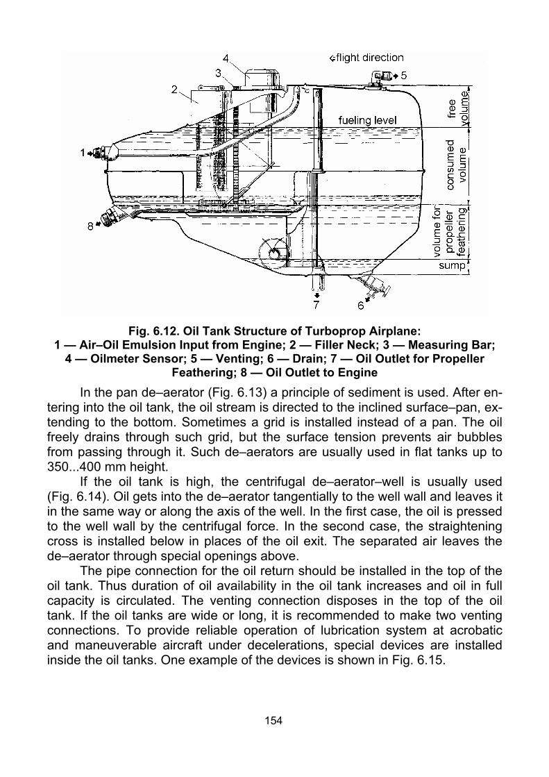
154
Fig. 6.12. Oil Tank Structure of Turboprop Airplane:
1 — Air–Oil Emulsion Input from Engine; 2 — Filler Neck; 3 — Measuring Bar; 4 — Oilmeter Sensor; 5 — Venting; 6 — Drain; 7 — Oil Outlet for Propeller
Feathering; 8 — Oil Outlet to Engine In the pan de–aerator (Fig. 6.13) a principle of sediment is used. After en-
tering into the oil tank, the oil stream is directed to the inclined surface–pan, ex-tending to the bottom. Sometimes a grid is installed instead of a pan. The oil freely drains through such grid, but the surface tension prevents air bubbles from passing through it. Such de–aerators are usually used in flat tanks up to 350...400 mm height.
If the oil tank is high, the centrifugal de–aerator–well is usually used (Fig. 6.14). Oil gets into the de–aerator tangentially to the well wall and leaves it in the same way or along the axis of the well. In the first case, the oil is pressed to the well wall by the centrifugal force. In the second case, the straightening cross is installed below in places of the oil exit. The separated air leaves the de–aerator through special openings above.
The pipe connection for the oil return should be installed in the top of the oil tank. Thus duration of oil availability in the oil tank increases and oil in full capacity is circulated. The venting connection disposes in the top of the oil tank. If the oil tanks are wide or long, it is recommended to make two venting connections. To provide reliable operation of lubrication system at acrobatic and maneuverable aircraft under decelerations, special devices are installed inside the oil tanks. One example of the devices is shown in Fig. 6.15.

155
Fig. 6.13. Pan De–Aerator Fig. 6.14. Centrifugal De-aerator-Well
Fig. 6.15. Oil Tank with Device Ensuring Oil to Engine Supply at Decelerations:
1 — Technological Hatch Covering; 2 — Pipeline Connection; 3 — Measuring Bar; 4 — Measuring Pocket; 5 — Air Intake Counterweight; 6 — Filler Neck; 7 — Tank; 8 — Pan De–Aerator; 9 — Pipe Supplying Oil on the Pan De–Aerator; 10 — Air–Oil Emulsion Pipeline Connection; 11 — Oil Outlet; 12 —
Drain Valve; 13 — Hydraulic Seal Ring; 14 — Bushing; 15 — Oil Intake with Counterweight; 16 — Bushing; 17 — Axis;
18 — Washer; 19 — Ring; 20 — Air Outlet
Checklist 1. What is lubrication system intended for?

156
2. What requirements are made to aviation engine lubrications systems? 3. What properties of oils are main during oil selection for aviation en-
gines? 4. What is the difference between (bypass) turbojet and turboprop lubri-
cation systems? 5. Make comparative analysis of direct and reverse schemes of lubrica-
tion system. 6. What are the advantages of shorted and double-circuit schemes of lu-
brication system? 7. What measures are usually taken to decrease air quantity in oil? 8. How to determine required capacity of oil tank? 9. What is altitude performance of lubrication system; and how is it pro-
vided? 10. Why is oil flow of scavenge pump in some times more than oil flow of
pressure pump? 11. Explain principle of centrifugal de-aerator operation. 12. In what way is oil coming from engine cooled? 13. What elements does oil tank consist of?

157
Theme 7. INTERNAL AERODYNAMICS OF POWER PLANTS
7.1. General Questions and Problems of Internal Aerodynamics The section of applied aerodynamics studying the air flow inside an air-
craft is called internal aerodynamics. Respectively, external aerodynamics studies flow around aircraft by a counter airflow.
The most important problem of the internal aerodynamics is organization of airflow inside a power plant, which determines the engine cooling, power losses on cooling, engine thrust, etc.
Air ducts located inside the airplane should have the minimal pressure losses. In some cases the uniform field of speed in front of the air consumer is also required. It is essential for turbojet compressors and coolers.
Besides, it is required to organize the input, and sometimes the output of airflow so, that the related increase of aerodynamic drag is minimal. It is neces-sary to note, that requirements of internal aerodynamics often come into con-flict with those of external aerodynamics.
7.2. Standard Air Duct Segments. Pressure Losses During Air Motion There are air ducts of various overall dimensions and designs. However
the main air ducts segments are always the same. To provide the visualization of this statement we shall consider an axial-
symmetric jet engine air duct (Fig. 7.1, a) and an air-oil cooler air duct (Fig. 7.1, b).
The Н cross–section corresponds to the undisturbed airflow. In theory it lies on the infinite distance far from the е cross–section.
The affluence segment (Н–е) of the sucked air is located in front of the air intake. The purpose of this segment is to brake the airflow and increase pressure. That’s why it is also called the external diffuser.
The input segment (1–2) is designed in the form of confuser to ensure the small airflow compression, in order to avoid the airflow separation in the air intake at the big angles of attack or slipping. This segment is far shorter than the following one.
The diffuser (2–3) is a widening duct in which the airflow speed de-creases, and the pressure increases.
The air duct channel (3–4) is required if the air intake lies far from the air consumer for the design reasons. Sometimes, this segment has a curved axis according to the onboard airplane arrangement.
Segment 4–5. In this segment, the axis of channel 3–4 is aligned with the axis of the air consumer. This segment is required, only if these axes do not co-incide. The segment is ( )d150 .... long.
Segment 5–6 represents a confuser. In this segment airflow speed slightly increases to obtain more uniform field of speed in front of the air consumer.

158
a
b
Fig. 7.1. Standard Air Duct Segments Segment 7–8 presents only in cooler ducts. In this segment the airflow is
accelerated again to decrease external drag: ( )aHAPP VVmX −=. , where Am — mass second air consumption, through the channel; HV , aV — ram airflow and airflow speeds in a cross-section. Apparently, if speed aV is less, than HV , additional drag appears.
Pressure losses at air motion in the air duct are conditionally subdivided into two kinds: friction losses and losses in diffusers.
Friction losses are calculated by the usual formula
∑=
ρλ=∆
n
1i
2i
i
iifr 2
VdlP ,
where i — a number of segment having approximately constant area and pe-rimeter of the channel cross–section; PF4di = — a hydraulic diameter of the channel cross–section; F , P — the area and perimeter of the channel cross–section; iλ — the coefficient of friction, which is taken from reference books; other parameters are obvious.

159
7.3. Diffuser. Losses in Diffusers Diffuser is a channel, at motion along which speed of flow decreases. It is
known that there are subsonic and supersonic gas flows. Respectively, we subdivide the diffusers into subsonic and supersonic. In this section we shall consider designing of subsonic diffusers. Designing of supersonic diffusers will be considered in the «Supersonic air intakes» section. It is known that subsonic flow brakes in the widening duct. Thus a subsonic diffuser is a widening duct, along which axis the flow speed decreases, and pressure increases.
The formula for calculation of losses at sudden expansion (impact), (Fig. 7.2, a) is known from the hydraulics:
( )
2
2
12
12
1
22
1221impact F
F12V
VV1
2VVV
2P ⎟⎟
⎠
⎞⎜⎜⎝
⎛−
ρ=⎟⎟
⎠
⎞⎜⎜⎝
⎛−
ρ=−
ρ=∆
, where 1V , 2V — speeds before and after sudden expansion of the channel; 1F ,
2F — cross–sectional areas of the channel before and after expansion.
a b c
Fig. 7.2. Types of Diffusers with Straight-line Generatrix In calculations the pressure losses in the diffuser are usually compared
with the losses at impact, using the impact softening factor:
impact
difdif
PPP
∆∆
=∆.
The simplest type of the diffuser is the diffuser with straight–line genera-trix and constant expansion angle (Fig. 7.2, b).
Apparently, even if the angle is 40° (25° for square cross–section), losses in the diffuser become equal to losses at impact. The optimal expansion angles α (angles at which the sum of friction losses and expansion losses is close to minimum) are 6...10° for round diffuser cross–section and 5...8° for square dif-fuser cross–section. This results in the long length of diffusers (and as a result big mass), which is undesirable, because of the growth of friction losses and complications of their arrangement onboard an aircraft.
The main pressure gain and losses in the diffuser are concentrated in the beginning part of the diffuser (where the speed is high). Hence, it is necessary to provide good performance of the diffuser in this section. Even if thus, per-formance of a tail section where the speed is low will worse. It is the main idea of designing of diffusers of small length.
The stepwise diffuser is a simple realization of this idea (ref. Fig. 7.2, c).

160
Fig. 7.3. Relation of Impact Softening Factor from Diffuser Expansion
Angle for Diffusers with Straight–Line Generatrix Another implementation of the idea is the application of diffusers with cur-
vilinear generatrix, which have the small expansion angles in the high–speed section and large in the low–speed field. Besides, the curvature of the walls de-termines a positive pressure gradient from the wall to the axis, which reduces the danger of the airflow separation. The most successful are curvilinear diffus-ers with a constant length pressure gradient ( constdxdP = ) and with a con-stant length velocity gradient ( constdxdV = ). Fig. 7.4, a shows three diffus-ers with the same pressure losses and Fig. 7.4, b shows three diffusers with the same length.
a b
Fig. 7.4. Diffusers with Curvilinear Generatrix First from them is the best if the short ducts with the large rate of braking
are designed. Usually they are used for inlet ducts of cooler tunnels and cowl-ings of piston engines.
161
Diffusers of the second type are widely used for jet engines air intakes. As they have smoother outlines and provide more uniform field of speed in the jet engine inlet. Thus, they usually result in greater length.
Besides the considered questions, when designing the channels of air ducts, a lot of other problems are also solved, such as: the stream compression to provide uniformity of the field of speed, the stream turns, struggle against boundary layer at entry of air intake, provision of rational stream exit from the cooler ducts, the provision of the air intakes performance at the angles of attack and slipping, the pressurization of air duct channels.
Checklist 1. What is internal aerodynamics? 2. List segments of typical jet engine air duct. 3. Specify features of air-oil cooler air duct. 4. What types of pressure losses at air motion along air duct do you
know? 5. What is diffuser? What is the difference between subsonic and super-
sonic diffusers? 6. What types of diffusers with straight-line generatrix do you know? 7. What is impact softening factor? 8. What are the values of optimal expansion angles in diffusers with
straight-line generatrix? 9. Why do diffusers with straight-line generatrix have very restricted
application? 10. What is the main idea of designing of small length diffusers? 11. What types of diffusers with curvilinear generatrix do you know?
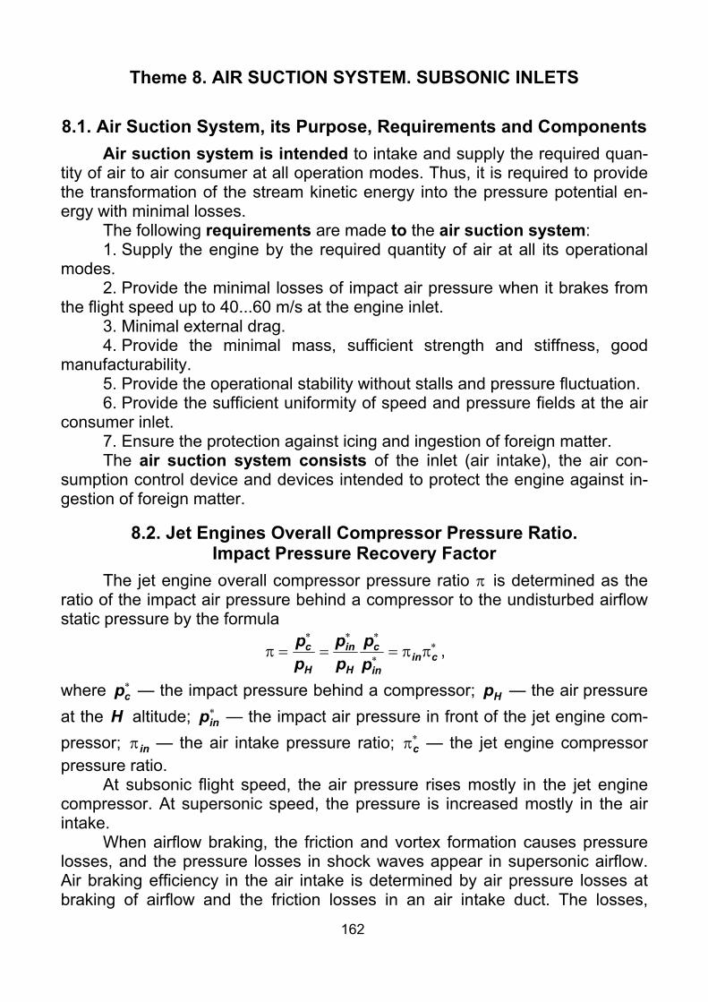
162
Theme 8. AIR SUCTION SYSTEM. SUBSONIC INLETS
8.1. Air Suction System, its Purpose, Requirements and Components Air suction system is intended to intake and supply the required quan-
tity of air to air consumer at all operation modes. Thus, it is required to provide the transformation of the stream kinetic energy into the pressure potential en-ergy with minimal losses.
The following requirements are made to the air suction system: 1. Supply the engine by the required quantity of air at all its operational
modes. 2. Provide the minimal losses of impact air pressure when it brakes from
the flight speed up to 40...60 m/s at the engine inlet. 3. Minimal external drag. 4. Provide the minimal mass, sufficient strength and stiffness, good
manufacturability. 5. Provide the operational stability without stalls and pressure fluctuation. 6. Provide the sufficient uniformity of speed and pressure fields at the air
consumer inlet. 7. Ensure the protection against icing and ingestion of foreign matter. The air suction system consists of the inlet (air intake), the air con-
sumption control device and devices intended to protect the engine against in-gestion of foreign matter.
8.2. Jet Engines Overall Compressor Pressure Ratio. Impact Pressure Recovery Factor
The jet engine overall compressor pressure ratio π is determined as the ratio of the impact air pressure behind a compressor to the undisturbed airflow static pressure by the formula
∗∗
∗∗∗
ππ===π cinin
c
H
in
H
c
pp
pp
pp ,
where ∗cp — the impact pressure behind a compressor; Hp — the air pressure
at the H altitude; ∗inp — the impact air pressure in front of the jet engine com-
pressor; inπ — the air intake pressure ratio; ∗πc — the jet engine compressor pressure ratio.
At subsonic flight speed, the air pressure rises mostly in the jet engine compressor. At supersonic speed, the pressure is increased mostly in the air intake.
When airflow braking, the friction and vortex formation causes pressure losses, and the pressure losses in shock waves appear in supersonic airflow. Air braking efficiency in the air intake is determined by air pressure losses at braking of airflow and the friction losses in an air intake duct. The losses,

163
caused by the air compression in the air intake, are estimated by the impact pressure recovery factor inσ . This factor represents the ratio of the impact pressure in front of the compressor to the impact pressure of the isoentropic broken stream:
∗
∗
=σH
inin p
p .
Decreasing the inσ value leads to the pressure decrease at the compres-
sor inlet ⎟⎟⎠
⎞⎜⎜⎝
⎛σ=π
∗
H
Hinin p
p , the thrust decrease and the increase of fuel consump-
tion. (For example, decreasing inπ by 30 % at 52M .= causes the 45 % engine thrust decrease and 15% increase of the specific fuel consumption). Therefore, one of the main requirements made to inlets is to provide the greatest possible
inσ .
8.3. Air Intake Classification The type of air intake depends on the design M number, the required M
number range, the type of engine, its arrangement, and other factors. According to the flight speed, air intakes are divided into subsonic, tran-
sonic and supersonic (Fig. 8.1). According to the arrangement on aircraft, the air intakes can be nose, lateral, ventral, under–wing.
Nose air intakes are located in the nose of a fuselage or in the front of an engine nacelle. The advantages of these air intakes include:
[+] design simplicity; [+] uniformity of the entry field of speed; [+] low hydraulic pressure losses; [+] absence of entry boundary layer. Lateral air intakes are located on each side of a fuselage. They can be
semicircle, flat with vertical ramp, flat with horizontal ramp (scoop). Such air in-takes have usually specific features for example: high hydraulic pressure losses and the entry boundary layer. However, thus the fuselage volume is used much better for the arrangement of fuel and equipment.
The ventral and under–wing air intakes. The deficiency of these air in-takes consists in the bad operation at the big negative angles of attack. At the same time such arrangement of air intakes is favorable for supersonic aircrafts. As the supersonic airflow can be broken in a shock system of the airplane, it is possible to apply the subsonic air intakes at supersonic aircraft (F-16, F-18). If the supersonic air intake is used, the aircraft lift is increased by the pressure growth in front of it, as the pressure is applied to the lower surface of the fuse-lage or the wing.
Besides, air intakes are classified by the cross–section shape, the boundary layer control method and degree of mechanization.

164
Fig.
8.1
. Air
Inta
ke C
lass
ifica
tion

165
8.4. Designing Model and Design Algorithm of Subsonic Air Intakes The initial data at designing the air intakes include: the flight speed HV ,
the flight altitude H , the engine diameter by the compressor enD and the air consumption aG [kg/sec] for this flight mode.
Within the subsonic air intake design, four problems should be solved: the inlet area determination; the external and internal outlines shaping and the air intake lip forming.
The airflow in front of the air intake depends on the ratio of the flight speed HV and air speed eV into the inlet. There are possible three flow modes (Fig. 8.2).
a b c
Fig. 8.2. Operational Modes of Subsonic Air Intake At eH VV < , the airflow accelerates in front of the air intake (Fig. 8.2, a). At
eH VV = , the air stream enters the diffuser without changing the shape (Fig. 8.2, b). At eH VV > , the airflow decelerates in front of the air intake (Fig. 8.2, c), and the pressure losses decrease in the air intake. The last case corresponds to the design mode of the air intake operation.
The inlet area, m2, is determined by the formula
come
ae V
GFρ
= ,
where eV — the air speed into inlet, m/s; comρ — the air density into the inlet taking into account compressibility, kg/m3: ( )[ ]2
e2HHcom V1M501 −+ρ=ρ . ,
where Hρ — the air density at the flight altitude, kg/m3 (is taken from the Inter-national Standard Atmosphere, ГОСТ 4401-81 «Атмосфера стандартная»);
Hee VVV = — the relative speed into inlet 120Ve ....= . In order to provide good external airflow about, it is recommended to assume 7050Ve .....= .
If the air consumption through the engine at design flight mode is un-known, it can be determined by the formula
( ) ( )3600
HMPHMCLG P0a
,,α= ,
where 0L — stoichiometric coefficient, kg/kg; α — the air excess coefficient; ( )HMCP , — the specific fuel consumption at the design mode, kg/N⋅hour; ( )HMP , — engine thrust at the design mode, N.

166
The external outlines and lip are shaped by condition of minimum aero-dynamic drag. That’s why it is necessary to obtain radius of curvature in mid–section as greater as possible and smooth lengthwise growth of the radius of curvature.
Elliptical outlines meet these requirements. In this case, the design be-gins with the «skeletal» line, in the form of ellipse. Then, an external outline will be put aside from this «skeletal» line, in the form of ellipse too (Fig. 8.3).
The location of the «skeletal» line is determined by the affluence angle β , determined by the formula, rad:
1V1
180K
e−
⋅π=β β .
The βK coefficient depends on the shape of the air intake in the front view: 22K =β — for round air intakes; 26K =β — for the rectangular air in-takes.
To design the «skeletal» line, we use the equation of an ellipse, which major semiaxis equals to 0LL + , and the minor semiaxis equals to 2D 0M :
( ) ( ) 1
2Dy
LLx
2M
2
21
2
0
=++
.
The external outline is shaped by the ellipse with semiaxes δL and δ . The ordinates of the ellipse are put aside normally to the «skeletal» line
Fig. 8.3. Designing Model of Subsonic Air Intake

167
1yLx 2
2
2=
δ+ δ
δ
δ .
The radius of curvature of air intake lip is approximately assumed: e1 FK=ρmin , 050040K1 .....= .
The engine nacelle mid-section diameter is assumed equal to: en2M DKD ⋅= , 3121K2 .....= .
The semiaxes δL and δ are determined by the ratios:
δ
ρ=δ min ,
δδ
=δL , 25010 .....=δ .
The semiaxes of «skeletal» line ellipse are determined by the formulas
δ−= 2DD MM0,
β
−=
tgD2DD
Le
2e
2M0 ,
Me1 DD1
LLL−
=+ .
To provide the low aerodynamic drag of the external outlines, it is expedi-ent, that
( ) 2H
MM351
DL ....≥ ,
where HM — the M flight number. To provide the good operation of the air intake on the stop, the area of the
minimal cross–section is assumed equal to: e4 FKF =min , 9080K4 .....= .
Thus, the radius of curvature of the lip is obtained equal to:
( )β−−
=sin
min
12DDR e
1 .
Finally we assume the greater value of the lip radius of curvature: { }1RR ,max minρ= .
Now all parameters are specified, and it is possible to design the «skele-tal» line by the ellipse equation:
( )21
2M
LLx1
2D
y 0
+−= .
Then the ordinates of the ellipse of external outline are put aside normally to the «skeletal» line:
2
2
Lx1yδ
δδ −δ= .
The internal outlines are shaped by one of the previously considered laws: constdxdP = or constdxdV = . In the first case, the following formula is used:

168
( )11
FF
RLx
FxF
2
22
2
+⎟⎟⎠
⎞⎜⎜⎝
⎛−
β−
=
mincos
,
in the second case: ( )11
FF
RLx
FxF2
2
+⎟⎟⎠
⎞⎜⎜⎝
⎛−
β−
=
mincos
,
where 4DKF
2en
52π
= — the cross–sectional area of the channel at the end of
the diffuser, 1K5 ≥ — the confuser factor.
8.5. Subsonic Air Intake Design Air intakes of subsonic aircrafts of round cross–section are designed as
fuselage-type aircraft assemblies (Fig. 8.4). That is, they consist of transversal frame and longitudinal stringer sets, together with the outer and inner skins. Certainly, the inner skin is riveted by the countersunk rivets to reduce pressure losses.
The air intake lip is usually supplied with the hot air deicing system (Fig. 8.5).
Sealing in air intakes design is reached by using of rubber or other seals in detachable joints in the form of hollow profiles.
The air intakes elements are made of aluminium alloys and high–strength composite materials (fiberglass plastic, boron plastic, black–reinforced plastic).
Fig. 8.4. Subsonic Bypass Turbojet Air Intake
It is necessary to note, that the quality of internal surface of air intakes must meet the high requirements, because of the extruded rivet heads and ledges on skin joints, excessive roughness result in increase of pressure losses and vortex generation, which increases fuel consumption and decreases en-gine thrust.
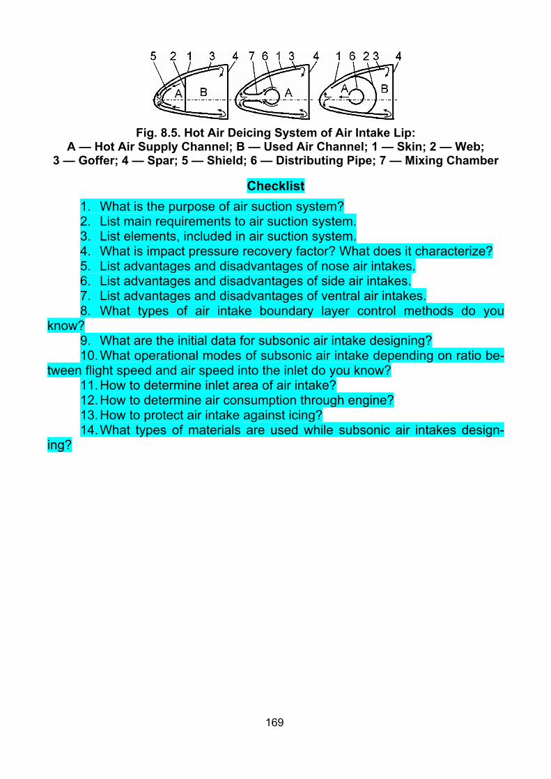
169
Fig. 8.5. Hot Air Deicing System of Air Intake Lip:
А — Hot Air Supply Channel; В — Used Air Channel; 1 — Skin; 2 — Web; 3 — Goffer; 4 — Spar; 5 — Shield; 6 — Distributing Pipe; 7 — Mixing Chamber
Checklist 1. What is the purpose of air suction system? 2. List main requirements to air suction system. 3. List elements, included in air suction system. 4. What is impact pressure recovery factor? What does it characterize? 5. List advantages and disadvantages of nose air intakes. 6. List advantages and disadvantages of side air intakes. 7. List advantages and disadvantages of ventral air intakes. 8. What types of air intake boundary layer control methods do you
know? 9. What are the initial data for subsonic air intake designing? 10. What operational modes of subsonic air intake depending on ratio be-
tween flight speed and air speed into the inlet do you know? 11. How to determine inlet area of air intake? 12. How to determine air consumption through engine? 13. How to protect air intake against icing? 14. What types of materials are used while subsonic air intakes design-
ing?

170
Theme 9. SUPERSONIC AIR INTAKES
9.1. Shocks. Shock Creation Methods. Types of Supersonic Air Intakes
The supersonic air intake (Fig. 9.1, a) usually represents supersonic (А) and subsonic (В) diffusers connected together; being practically an inverted Laval nozzle. Structurally the supersonic air intake consists of a central body 1 and shell 2.
In ideal gas, the transition from supersonic to subsonic flow occurs in the diffuser throat. In such ideal diffuser the non–viscous stream is braked isoen-tropically without formation of shocks and boundary layer in the converging section of the channel, till the sonic speed in the throat ( 01M .= ), so it operates without impact and static pressure losses.
a b
Fig. 9.1. Scheme of Supersonic Air Intake In real conditions it is possible to provide the transition from supersonic to
subsonic flow with impact pressure loses (the entropy growth) in a normal (di-rect) shock. It is implemented in the supersonic air intake. The subsonic stream is further broken in the extending subsonic diffuser.
In order to reduce the impact pressure losses, the supersonic flow is bro-ken by a various systems of oblique shocks, which are finished by a normal shock. These oblique shocks provide the small Mach number before the normal shock, which reduces impact pressure losses. Such systems of shocks are effi-cient at the high supersonic speed. Up to 51M .= , there is no effect from using this type of system of shocks. That is why at such speeds, transonic air intakes with one direct shock are used (Fig. 9.1, b).
According to the location of this system of shocks in the air intake, the fol-lowing air intakes are available: the air intakes with external compression (Fig. 9.2, а), the air intakes with internal compression (Fig. 9.2, b) and the air intakes with mixed compression (Fig. 9.2, c).
The type of compression is chosen depending on the cruising flight speed, flight speed range and purpose of the aircraft.
The system of shocks with external compression is usually formed by the system of turns. It can result in the total turn angle exceeding the limit turn stream angle for the specified M flight number (Fig. 9.3). In this case the sys-

171
tem of shocks (Fig. 9.4, a) will be destroyed; and the detached head wave is formed in front of the air intake (Fig. 9.4, b). This wave has much greater drag and the higher impact pressure losses, than the system of shocks.
a b c Fig. 9.2. Schemes of Supersonic Air Intakes by
Arrangement of Shock System The system of shocks with external compression has the minimal impact
pressure recovery factor among three considered schemes. Its advantage con-sists in the low boundary layer thickness and regulation simplicity. These air in-takes are applied for supersonic aircrafts with sharply varying parameters of ex-ternal airflow, maneuverable, with wide altitude and speed ranges.
Fig. 9.3. Total Turn Stream Angles iα for Optimal External Compression Diffusers with Number of Shocks n and Limit Stream Turn Angles maxα
Dependence on Flight Mach number
Fig. 9.4. Attached Oblique Shock (a) and
Detached Head Wave (b)
The system of shocks with internal compression is arranged completely inside the air intake. As a result, the boundary layer has the maximum impact

172
to the system of shocks here. Such air intakes are more difficult to regulate and start. However, this type of air intake has the highest impact pressure recovery factor among the considered schemes.
The systems of shocks with mixed compression are formed by combi-nation of above considered systems. Such systems take intermediate place be-tween earlier considered ones by the impact pressure recovery coefficient, by regulation simplicity and by boundary layer impact. It usually has no problem with limit turn stream angle.
By cross–section shape, supersonic air intakes are divided into flat and axially–symmetrical. Flat air intakes have smaller angles of stream deflection and are easier regulated.
As with flight speed increase, boundary layer harmful effect increases too (for example, decrease of effective air consumption, increase of velocity field irregularity and vortex generation), than special boundary layer control methods are applied for supersonic air intakes (See Fig. 8.1). Boundary layer outflow is air intake displacement from airplane surface for boundary layer thickness with its following bleeding sideways from air intake. Boundary layer blowing with the purpose of its acceleration is provided by high pressure air supply into special air intake slots. Boundary layer suction is provided through set of holes on the internal air intake surface, connected with low pressure zone (usually with engine cooling system). Vortex generator installation turns laminar air flow to turbulent, which delays boundary layer separation.
9.2. Dependence of Impact Pressure Recovery Factor on M Flight Number and Number of Shocks
Optimal supersonic air intake designing is based on the work [37], in witch two problems of optimization of system of shocks for flat air intakes have been defined and successfully solved. The first problem has been defined as follows: for the given speed and flight altitude, determine number and arrange-ment of the oblique shock system with closing direct shock, which provides the maximum impact pressure behind the system of shocks. The second problem: at the same conditions, provide maximum static pressure behind the system of shocks. The first problem has the greatest practical value.
It is necessary to note, that the impact pressure recovery factor of system is maximal, if all impact pressure recovery factors are equal among them-selves.
Results of this work are given in tables or graphs of dependence of the maximum impact pressure recovery factor on the M flight number and number of oblique shocks before the direct one (Fig. 9.5).
Supersonic air intakes are designed on the basis of this work. Designing is carried out for the design mode (usually it is close to maximum flight speed).

173
Fig. 9.5. Dependence of Impact Pressure Recovery Factor on M Flight Number
and Number of Oblique Shocks for Optimum Systems of Shocks
9.3. Design Model and Design Algorithm of Supersonic Air Intakes When designing the supersonic air intake, the following problems should
be solved: 1. Selection of the number of shocks. 2. Calculation of the inlet area. 3. Shaping the central body. 4. Shaping the shell. 5. Shaping the internal air duct. Let's consider the design algorithm of the flat air intake with external
compression. The initial data for calculation are: am — the air consumption through the engine, kg/s; HM — M flight number; H — the flight altitude.
It is necessary to note, that the air intake is designed for the specified flight mode, for which its parameters are optimum. At the other flight modes, the impact pressure losses can appear inadmissible, that is the air intake regu-lating is required. One more reason for regulating the supersonic air intake is complication of reaching of the design mode.
In view of the air intake arrangement, the M number is determined before it as follows:
– for nose air intakes: Hdes MM = ; – for under–wing air intakes: ( )050040MM Hdes .....−= ; – for lateral air intakes: 051MM Hdes .−= .

174
Number of shocks n is chosen on the base of the graph (Fig. 9.5). The impact pressure recovery factor at each shock is determined as n -th power root of the impact pressure recovery factor taken from the graph (Fig. 9.5): n
i maxσ=σ . Inlet area eF is determined by the condition when the maximum air con-
sumption at the design flight mode is provided:
HH
ae V
mFρ
= ,
where Hρ — the air density at the design altitude; HV — the flight speed. For shaping the central body, it is necessary to know the stream turn
angles at each shock iα (Fig. 9.6). These calculations are carried out on the base of the oblique shock theory. The impact pressure recovery factor for the oblique shock is given by the relation:
1k
1
i22
i
1kk
i22
i
i22
i1k1k
i
21kkM
1
M2
1k1
M2
1k
−
−
−+
⎟⎠⎞
⎜⎝⎛ −
−β⎟⎟⎟⎟
⎠
⎞
⎜⎜⎜⎜
⎝
⎛
β−
+
β⎟⎠⎞
⎜⎝⎛ +
=σ
sinsin
sin ,
where 41k .= — ratio of the air thermal capacity at constant pressure to the thermal capacity at constant volume; iM — M number before i -th shock; iβ — the shock front deflection angle from the initial direction of the stream.
Fig. 9.6. Design Model of Supersonic Air Intake
Let's denote i22
iMx β= sin . As the impact pressure recovery factor at i –the shock is already known, then it is possible to find x by any numerical method. For example, we can use iteration method from the equation:

175
( )( )712
7572i
2120x41x201x
.... −+σ
= .
Expressing angles iβ by using them, we obtain:
i
i Mxarcsin=β .
Then, with known iβ angle and M number before shock iM , the M num-ber behind the shock 1iM + is given by the expression:
i
22i
i22
i
i22
i
2i
1i M5M5
1M7M5M
β+β
+−β
+=+ sin
cossin
.
From last two equations angles iβ and M numbers behind shocks 1iM + are consistently determined.
Stream turn angles at each shock iα are determined by the equation:
⎥⎦
⎤⎢⎣
⎡β⎟⎟
⎠
⎞⎜⎜⎝
⎛β
+−β=α ii
22i
ii tgM6
561arctg
sin.
For axially–symmetrical air intakes, there in no exact solution. Therefore, for their designing, at first the flat air intake is designed, and then we pass to the cone angles using the ( )wedcon αα diagram. Otherwise, the axially–symmetrical air intake can be designed using nomogram from reference books.
When shaping the shell it is necessary to satisfy two conditions: – to organize air flow on the inner shell surface, it is necessary to provide
the inner shell angle θ equal to the total stream turn angle in the shell lip and – to create the attached oblique shock on the outer shell surface, it is
necessary to provide the outer shell angle κ less than limit stream turn angle maxα .
For external compression air intakes, the first condition is formulated as follows: to create closing direst shock between the wedge and the shell, it is necessary to provide the inner shell angle θ equal to the total stream turn an-gle on the wedge Σα .
It is easily to satisfy the first condition separately. For this purpose, it is enough to set: Σα=θ .
Fig. 9.3 shows, that the total stream turn angle for the optimal shock systems with 3n ≤ is less than limit one. But the outer shell angle γ+θ=κ . And γ angle cannot be less than ( )°84... , by the strength and stiffness conditions. Thus already for 3n = , we obtain maxα>γ+α=κ Σ (ref. Fig. 9.3). And the direct (detached) shock is created (Fig. 9.7, b) instead of oblique (attached) one (Fig. 9.7, a). It re-sults in the big impact pressure losses and external drag increase.
Thus, to meet the second requirement with 2n > , it is appropriate mixed compression air intakes application.

176
a b Fig. 9.7. Air Intake Shell Designing
The internal duct is shaped in the following way. Behind the direct shock, the internal duct is designed convergeding (Fig. 9.8). In such converging duct, the subsonic flow is accelerated and becomes supersonic again in the critical section. Further the duct is expanded. In such duct, the supersonic flow is accelerated. After that, the second direct shock is located. The reason of this second direct shock is the counterpressure in the duct in front of the engine. This supersonic airflow area is required to prevent the engine disturbances from affecting the system of shocks and to increase operational stability of the air intake.
Fig. 9.8. Supersonic Air Intake Duct
At this step, the slot and throat areas are calculated by the gas dynamics formulas. When shaping the duct, these sections are usually connected by a smooth curve of the second order.

177
9.4. Operation of Air Intakes at Off-design Conditions The air intake operational mode is characterized by the ratio of required
reqm and available avm air consumption, the impact pressure recovery factor
inσ (the ratio of the impact pressure behind the air intake to the impact pres-sure in front of it), the flow coefficient maxav mm=ϕ (the ratio of the available air consumption avm to the maximum possible one maxm ) and external drag coefficient xC (Fig. 9.9).
The air intake operational modes can be steady and unsteady. At steady modes, the flow parameters do not change during the time. Unsteady modes are characterized by the fast variation of flow parameters during the time.
The critical mode of operation is a particular case of a steady mode at which the required air consumption is equal to available one (Fig. 9.10, b).
Fig. 9.9. inσ (a), ϕ (b) and xC (c) Coef-ficients Dependence on
(Bypass) Turbojet Reduced Number of Revolutions
Fig. 9.10. Supercritical (a), Critical (b) and Subcritical (c) Operational Modes
of Supersonic Air Intake
At decreasing reqm , the air intake gets to the subcritical operational mode (Fig. 9.10, c). The available air consumption through the air intake de-creases due to the stream overflow in front of the shell. In this case, the flow coefficient decreases sharply and becomes less than one. This mode is char-acterized by the head wave at inlet. The air intake drag coefficient intensively

178
increases. The impact pressure recovery factor variates a little. The air flow is subsonic everywhere inside the air intake duct.
At increasing reqm , the air intake gets to the supercritical operational mode (Fig. 9.10, a). In this case, the shock–wave system remains constant; but air pressure before the engine decreases (because of the available air con-sumption through the air intake cannot farther increase). Matching of air con-sumptions becomes possible, when the normal shock, which is formed behind the throat, moves downstream. The pressure losses inside the air intake in-crease. In this case, the air pressure before engine is decreased exactly so much, that required and available air consumption becomes equal. In this case, the impact pressure recovery factor falls, which leads to the engine thrust de-crease.
If the Mach numbers are less than designed one (Fig. 9.11), the shock deviation angles iβ increase, and the shocks are not focused in the shell lip. Therefore the flow coefficient decreases, and the additional drag appears. In addition, the ram pressure of the undisturbed airflow sharply decreases, which leads to the pressure and air density decreasing inside the air intake throat. That is, when Mach number decreases, both the shock–wave system air con-sumption, and throat air consumption decrease simultaneously. But the latter decreases considerably faster. If the throat area is selected on the basis of the design operational mode of the air intake, then if the Mach numbers are less than designed, the throat cannot pass the total air consumption, which passed through the oblique shock–wave system. As a result, the head wave is formed in front of the inlet (Fig. 9.11, c); this head wave provides decreasing of the available air consumption due to air overflow, and the drag coefficient consid-erably increases.
If the throat area is selected greater, than it is necessary for the design mode, then the head wave formation can be prevented in a narrow range of Mach numbers which are smaller than the design one (Fig. 9.11, b).
If the Mach numbers are greater than designed one (Fig. 9.12), the shock deviation angles iβ decrease. The shocks hit not in the lip of the air in-take shell, but on its internal surface, and the airflow inside the duct becomes very complex, as a result of mirroring of these shocks. In addition, the undis-turbed supersonic flow starts accelerating in the air intake part free from oblique shocks, when getting into it. The throat pressure and fields of speed become sharply irregular. The impact pressure loses in the shock–wave sys-tem increase due to increase of shocks intensity and specified irregularity.
At the subcritical operational modes (Fig. 9.12, c), the head wave is always formed. In this case, with the Mach number increase, impact pressure recovery factor decreases, due to shocks intensity increase. The flow coeffi-cient also decreases, as a result of air overflow behind the head wave. The drag coefficient increases due to the formation of the strong head wave.
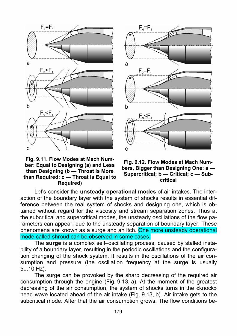
179
Fig. 9.11. Flow Modes at Mach Num-ber: Equal to Designing (a) and Less than Designing (b — Throat Is More
than Required; c — Throat Is Equal to Required)
Fig. 9.12. Flow Modes at Mach Num-bers, Bigger than Designing One: a — Supercritical; b — Critical; c — Sub-
critical
Let's consider the unsteady operational modes of air intakes. The inter-action of the boundary layer with the system of shocks results in essential dif-ference between the real system of shocks and designing one, which is ob-tained without regard for the viscosity and stream separation zones. Thus at the subcritical and supercritical modes, the unsteady oscillations of the flow pa-rameters can appear, due to the unsteady separation of boundary layer. These phenomena are known as a surge and an itch. One more unsteady operational mode called shroud can be observed in some cases.
The surge is a complex self–oscillating process, caused by stalled insta-bility of a boundary layer, resulting in the periodic oscillations and the configura-tion changing of the shock system. It results in the oscillations of the air con-sumption and pressure (the oscillation frequency at the surge is usually 5...10 Hz).
The surge can be provoked by the sharp decreasing of the required air consumption through the engine (Fig. 9.13, a). At the moment of the greatest decreasing of the air consumption, the system of shocks turns in the «knock» head wave located ahead of the air intake (Fig. 9.13, b). Air intake gets to the subcritical mode. After that the air consumption grows. The flow conditions be-

180
come close to design ones. The system of shocks is rebuilt. The closing shock is placed in zone of possible separation. The boundary layer is restored with the same parameters. Then there is a new separation, and the process is peri-odically repeated.
At the substantial growth of the required volumetric consumption through the engine the shock moves behind the diffuser throat. The supercritical mode is observed. The closing shock intensity can cause the separation of the boundary layer (Fig. 9.14). This stream separation is accompanied by high–frequency pressure oscillations. This mode is known as an itch. (In this case, the oscillation frequency makes 300...400 Hz).
Fig. 9.13. Surge Fig. 9.14. Itch At big thickness of boundary layer on the aircraft surface, located before
air intake, and at flight speed increase, that leads to shock waves intensity, boundary layer separation from this surface can happen. This phenomenon is especially probable at airplane angle of attack increase. In some arrangements such separated whirling mass of air, called shroud can hit into air intake. In this case, unsteady operational mode of air intake, which is also called shroud, is observed (Fig. 9.15). It is characterized by airplane shaking and hubble-bubble, going from air intake, airplane drag increase and engine thrust decrease, and by appearing of axial impulses because of thrust oscillation.
It is necessary to note, that the air intake operation at the unsteady modes is extremely undesirable, because pressure oscillation can result not only in engine stoppage in flight, but in breakage of both airframe elements (in-ternal skin of air intake and air duct), and engine (firstly — compressor).

181
Fig. 9.15. Shroud
9.5. Methods of Supersonic Air Intake Regulation The main problem concerning to the regulation of the air intakes, when
flight speed and the engine power are changed, is how to keep the required and available air consumption equal. It provides to save the system of shocks in the specified position.
The regulation can be carried out by: 1) Changing the inlet area; 2) Moving the central body or the shell; 3) Changing the throat area; 4) Air bleeding through by–pass valves. Changing the inlet area can be provided by movable forward part of the
flat air intake shell (Fig. 9.16).
Fig. 9.16. Air Intake Regulation by Inlet Area Changing (Simultaneously with
Throat Area Changing) Moving the central body allows to change the inlet air consumption
(Fig. 9.17). With the flight speed increase, the central body is extended forward. Thus oblique shocks remain focused in the shell lip. At the speed decrease, the
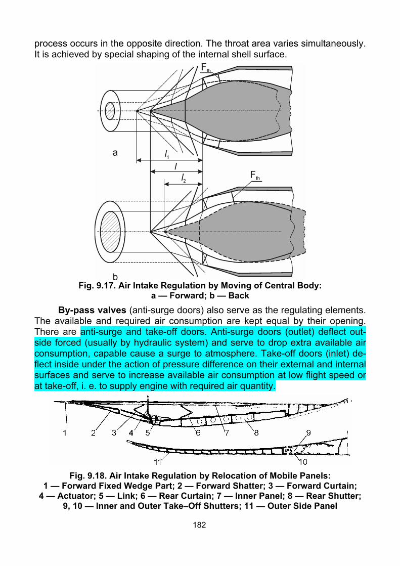
182
process occurs in the opposite direction. The throat area varies simultaneously. It is achieved by special shaping of the internal shell surface.
Fig. 9.17. Air Intake Regulation by Moving of Central Body:
a — Forward; b — Back By-pass valves (anti-surge doors) also serve as the regulating elements.
The available and required air consumption are kept equal by their opening. There are anti-surge and take-off doors. Anti-surge doors (outlet) deflect out-side forced (usually by hydraulic system) and serve to drop extra available air consumption, capable cause a surge to atmosphere. Take-off doors (inlet) de-flect inside under the action of pressure difference on their external and internal surfaces and serve to increase available air consumption at low flight speed or at take-off, i. e. to supply engine with required air quantity.
Fig. 9.18. Air Intake Regulation by Relocation of Mobile Panels:
1 — Forward Fixed Wedge Part; 2 — Forward Shatter; 3 — Forward Curtain; 4 — Actuator; 5 — Link; 6 — Rear Curtain; 7 — Inner Panel; 8 — Rear Shutter;
9, 10 — Inner and Outer Take–Off Shutters; 11 — Outer Side Panel

183
The direct change of the throat area include the relocation of the mobile panels or shaped inserts (Fig. 9.16, 9.18), the blowing of stream onto the cen-tral body surface in the throat zone, changing the central body diameter.
Regulating can be continuous or discrete.
9.6. General Arrangement of Air Intakes The design of the air intake is similar to the fuselage design. It is neces-
sary to make only a few remarks. 1. Flat walls should be avoided. Such walls are strongly loaded because
of the high pressure difference. If necessary, they must be reinforced by frames, embossings, sections.
2. All riveted joints should be sealed. 3. All detachable joints must be reliably locked. 4. It is necessary to provide controllability in service for the condition of
the air intake internal surface. 5. It is necessary to take into account the impulse loadings appearing dur-
ing surge. Otherwise these loadings can cause the air intake damage. 6. It is necessary to avoid the resonance oscillations of structural ele-
ments during surge. Structural materials for supersonic air intakes are practically the same
materials, as for subsonic ones. However titanium alloys and sometimes steel are more widely used here, because of small element thicknesses and big loadings.
Providing high efficiency and reliability of power plant makes require-ments to the air intake arrangement onboard an airplane. That is, it is nec-essary to take into account interference of the air intake and aircraft, air intake and engine. First of all, the air intake inlet conditions are the most important: the local speed of stream, the speeds non–uniformity and the local downwash angles.
When the air intake is arranged in a braking zone, it is possible to in-crease the impact pressure recovery factor and reduce the inlet area and drag.
The increase of speeds non–uniformity results in decreasing of the im-pact pressure recovery factor and decreasing of the surge margin.
The large local downwash angles (caused, for example, by the fuse-lage) contort the inlet theoretical conditions and disturb the design operation mode.
Flat and semicircular air intakes attached to the fuselage are better integrated to it, structurally are easily integrated in sheaves of two or four air in-takes, provide the greater regulating range of the flow area and have better characteristics at the large angles of attack.
The advantage of the axially-symmetrical air intake consists in the smaller mass and length, but they are difficult to be regulated in wide consump-tion range.

184
Flat air intakes, in comparison with the axially-symmetrical ones, are usu-ally characterized by the large change of the optimal wedge angle, than the change of the central cone angle, depending on the M flight number. It results in the greater range of deviations in the actuation system and increases its mass.
In view of above stated, three types of air intakes are widely used in the modern aviation: nose, attached to fuselage (lateral, ventral, dorsal) and wing (under-wing, over-wing).
Nose air intakes, round or oval cross-section, are used in the case of the arrangement of engines in fuselage or engine nacelle.
[+] Other airplane units practically do not affect to their operation. [+] Convenient flight instructor and student arrangement at engine tests
on ground; [–] They have long and complicated air duct (the mass of 1 m2 of the su-
personic air intake duct surface makes approximately 8...12 kg). [–] This air duct occupies the payload volume of the fuselage and makes
the fuel storage as well as the arrangement of the landing gear and other equipment more complicated.
The last disadvantage is eliminated if the engine is located in the nacelle. The cross-section of lateral air intakes attached to fuselage can be of
various shapes (rectangular with rounded corners, semicircular, semi–elliptical, a quarter of a circle, etc.) and are characterize by:
[+] Shortened air duct, which reduces the hydraulic pressure losses; [+] Absence of problem with the radar equipment arrangement; [–] One of them is usually shaded by the airplane during the slip maneu-
ver; [–] The boundary layer, formed on the fuselage, can affect the air intake
operation. [–] Impossibility of flight instructor arrangement sideways to student at
engine tests on ground; Dorsal and ventral air intakes are a variation of the lateral ones and
they are characterized by the reduced compression efficiency at the large an-gles of attack, because of the fuselage impact.
Under–wing and wing flat air intakes are most widely used nowadays on the heavy supersonic aircraft, despite of the great effect of engines to flow about the wing and cause a decline of its characteristics.
In this case two versions of arranging the braking surface are probable: horizontal and vertical.
The airplanes with horizontal arrangement of the braking surface (Tu-144, Concord), are characterized by the increase of the aircraft lift with the increase of the angle of attack and higher lift-to-drag ratio. These air intakes are less sensitive to the change of the angles of attack.

185
Air intakes with a vertical wedge (ХВ-70А, T-100) have essentially smaller (approximately 20%) length, due to the equalization of the inlet field of speed. They are less sensitive to lateral washes.
The wing and under–wing arrangement of the air intakes is expedient in the zones of minimal washes, that is as closer as possible to the aircraft plane of symmetry. Thus, it is necessary to provide the operation stability of the neighboring air intakes if the surge occurs in one of them.
Checklist 1. At what Mach numbers are supersonic air intakes applied, and at what
Mach numbers are transonic ones? What is the difference between them? 2. What types of shocks do you know? 3. What schemes of supersonic air intakes by arrangement of shock sys-
tem do you know? 4. Characterize system of shocks with external compression. 5. Characterize system of shocks with internal compression. Why is it not
used in aviation? 6. Characterize system of shocks with mixed compression. 7. How to select optimal number of shocks? 8. How to determine inlet area? 9. What two conditions should the shell of supersonic air intake with ex-
ternal compression meet? 10. Why is it rational to design air intakes with number of shocks more
than two with mixed compression? 11. How to shape internal duct behind the direct shock? 12. What are the main dimensionless parameters which characterize su-
personic air intake operation? 13. Characterize subcritical operational mode of supersonic air intake. 14. Characterize supercritical operational mode of supersonic air intake. 15. Characterize supersonic air intake operation at Mach numbers less
than designed ones and at throat area, selected for designed Mach number. 16. Characterize supersonic air intake operation at Mach number less
than designed one and at throat area, selected for Mach number less than de-signed.
17. Characterize supersonic air intake operation at Mach numbers, greater than designed.
18. What is surge? 19. What is itch? 20. What methods of supersonic air intake regulation do you know? 21. What structural materials are used for supersonic air intakes? 22. Characterize nose supersonic air intakes. 23. Characterize lateral supersonic air intakes.
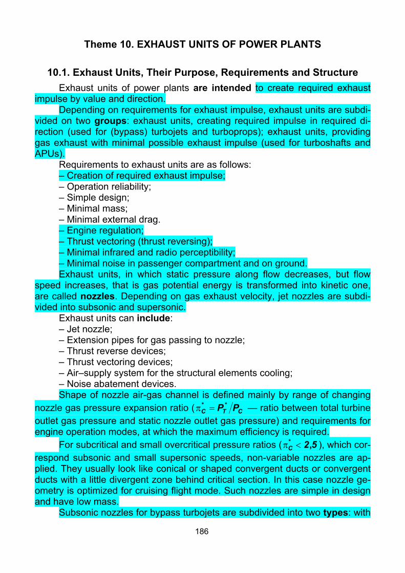
186
Theme 10. EXHAUST UNITS OF POWER PLANTS
10.1. Exhaust Units, Their Purpose, Requirements and Structure Exhaust units of power plants are intended to create required exhaust
impulse by value and direction. Depending on requirements for exhaust impulse, exhaust units are subdi-
vided on two groups: exhaust units, creating required impulse in required di-rection (used for (bypass) turbojets and turboprops); exhaust units, providing gas exhaust with minimal possible exhaust impulse (used for turboshafts and APUs).
Requirements to exhaust units are as follows: – Creation of required exhaust impulse; – Operation reliability; – Simple design; – Minimal mass; – Minimal external drag. – Engine regulation; – Thrust vectoring (thrust reversing); – Minimal infrared and radio perceptibility; – Minimal noise in passenger compartment and on ground. Exhaust units, in which static pressure along flow decreases, but flow
speed increases, that is gas potential energy is transformed into kinetic one, are called nozzles. Depending on gas exhaust velocity, jet nozzles are subdi-vided into subsonic and supersonic.
Exhaust units can include: – Jet nozzle; – Extension pipes for gas passing to nozzle; – Thrust reverse devices; – Thrust vectoring devices; – Air–supply system for the structural elements cooling; – Noise abatement devices. Shape of nozzle air-gas channel is defined mainly by range of changing
nozzle gas pressure expansion ratio ( CTC PP ** =π — ratio between total turbine outlet gas pressure and static nozzle outlet gas pressure) and requirements for engine operation modes, at which the maximum efficiency is required.
For subcritical and small overcritical pressure ratios ( 52C ,* <π ), which cor-respond subsonic and small supersonic speeds, non-variable nozzles are ap-plied. They usually look like conical or shaped convergent ducts or convergent ducts with a little divergent zone behind critical section. In this case nozzle ge-ometry is optimized for cruising flight mode. Such nozzles are simple in design and have low mass.
Subsonic nozzles for bypass turbojets are subdivided into two types: with

187
flow mixing and common nozzle; with separate exhaust. Nozzles with flow mixing are characterized by: [+] Higher efficiency as for specific fuel compression; [+] Reversing simplicity; [+] Simplicity of specified noise level achievement; [–] Bigger mass; [–] Difficulties with arrangement onboard an airplane because of bigger
interference drag. Structure of nozzle with flow mixing (Fig. 10.1) consists of: non-variable
nozzle, exhaust cone and flow mixer (of annular, injector, vortex or corrugated type).
Fig. 10.1. Subsonic Nozzle with Flow Mixing of Bypass Turbojet:
1 — Flow Mixer; 2 — Casing; 3 — Exhaust Cone; 4 — Nozzle; 5 — External Fairing of Nozzle
Nozzle with separate exhaust (Fig. 10.2) has two nozzles at external and internal counter outlets and is characterized by:
[+] Lower mass (in view of short length of external counter nozzle and flow mixer absence);
[+] Design simplicity; [+] Possibility of significant interference drag decrease and thrust in-
crease; [–] Reversing complexity; [–] Complex three-dimensional external air flow, depending on multiple
geometrical parameters of airplane and engine nacelle, which requires special investigation in three-dimensional statement and long-time tests on models.

188
Fig. 10.2. Subsonic Nozzle with Separate Exhaust:
1 — External Counter Nozzle; 2 — Internal Counter Nozzle
For supersonic flight speeds (especially with afterburner application) gas pressure expansion ratio 52C ,* >π , which requires Laval nozzle application. In Laval nozzle critical section, flow speed reaches local sonic speed. Further gas pressure decrease and exhaust velocity increase take place in divergent zone. It is necessary to note, that Laval nozzle is calculated for design flight mode. In this case, pressure losses in non-variable nozzle at off-design modes become inadmissible. To decrease these pressure losses, it is necessary to change ar-eas of critical and exhaust cross-sections, that is it is required to apply variable nozzles. Variable nozzles give high thrust in wide range of altitudes and flight speeds, improve starting engine performance and increase compressor stabil-ity.
Historically the first method of nozzle adjustment was axial movement of central body. But it had not further application because of difficulties with cool-ing of the central body and narrow range of area variation.
Next step was ejector nozzles application (Fig. 10.3). Supersonic zone of ejector nozzles is completely or partially replaced with supersonic free jet boundary, at that ejected air is supplied into the nozzle. Structure of ejector noz-zles consists of primary nozzle 1 and shell 2. Here, critical cross-section area variation is provided by movable eyelids, hinged on afterburner flange. Nozzle supersonic zone in this case is formed by ejector «flow duct». Air, supplied to ejector, is preliminary used for cooling of external afterburner shell. External part of the nozzle can be fixed (Fig. 10.3, a, b) or «feathered» (Fig. 10.3, c).
The disadvantage of ejector nozzles is big air consumption, required for ejector duct, which increases sizes and mass of airplane. The advantage is possibility of nozzles creation with wide range of flight Mach numbers.
Next step is gradual renunciation from «flow duct» and its replacement with eyelids structure. But such structure is extremely complex, and for gas flow without separation at 32M .> inadmissible length by arrangement and mass point of view is required. Therefore, for such Mach numbers, ejector noz-

189
zles are optimal solution.
Fig. 10.3. Ejector Nozzles
In the middle of 1970-th, for further maneuverability increase (by thrust vectoring) and airplane perceptibility decrease (by hot engine parts direct visi-bility exclusion and jet stream temperature decrease) flat nozzles (Fig. 10.4) were assumed perspective. Critical cross-section area variation is provided by movable subsonic eyelids. Thrust reversing is provided by further turn of sub-sonic eyelids, which open reverse ducts 5 and close critical cross-section. Thrust vectoring is provided by asymmetrical turn of supersonic eyelids. The nozzle allows to deflect thrust vector within range of ±20°. To decrease airplane perceptibility, nozzle eyelids must be in position, coordinated with other air-plane edges, and form jet stream so, that to decrease its temperature.
Fig. 10.4. Variable Flat Nozzle:
1 — Frame; 2 — Web; 3 — Supersonic Eyelids Actuators; 4 — Subsonic Eyelids and Reverse Actuator; 5 — Reverse Duct; 6 — Level; 7 — Subsonic Eyelid;
8 — Supersonic Eyelid
Disadvantages of flat nozzles are big mass (because of strength and ri-gidity) and big pressure losses in transition zone from circular cross-section behind turbine to flat one.

190
Fig. 10.5. Axisymmetric Nozzle with Swivelling Unit:
1 — Fixed casing; 2 — Thrust Vectoring Actuator; 3 — Axis of Rotation; 4 — Sealing Ring; 5 — Spherical Ring; 6 — Movable Casing; 7 — Nozzle Casing; 8 — Critical Section Hydraulic Actuator; 9 — External Eyelids; 10 — Subsonic Eye-
lids; 11 — Exhaust Section Pneumatic Actuators; 12 — Supersonic Eyelids; 13 — Guide of Supersonic Eyelids
Axisymmetric nozzles with thrust vectoring. There are several thrust vectoring methods: by means of Coand effect; by means of deflectors in nozzle exhaust zone; by mechanical deflection of nozzle or its part. Only last method is used nowadays.
Thrust vectoring system shall meet the following requirements: 1. System must operate at all engine operation modes. 2. Nozzle critical cross-section area is varied independently from thrust
vectoring and does not change at thrust vectoring. 3. Thrust vectoring frequency makes up to 50 movements per minute
within vertical plane and up to 25 within horizontal plane. 4. Angle variation speed is up to 30° per second, accuracy of specified
angle is ±0.1°. 5. Turbine exhaust pressure and gas consumption through nozzle at
thrust vectoring mode must be the same, as at direct flow exhaust and with the same nozzle pressure extension ratio *
Cπ .

191
6. In case of thrust vectoring system failure, nozzle must automatically turn in direct thrust position.
Axisymmetric nozzle with swivelling unit (Fig. 10.5) is an example of all nozzle mechanical deflection method realization. The swivelling unit is lo-cated in subsonic flow with high pressure. Such structure:
[+] Allows to modify existing engines; [+] Is relatively simple in design; [–] Allows thrust vectoring within one plane only; [–] Has narrow deflection angles range (±15°); [–] Requires grate forces of actuators. Example of part nozzle deflection is axisymmetric nozzle with thrust
vectoring in supersonic zone (Fig. 10.6). Here, swivelling unit is located be-tween subsonic and supersonic eyelids rows. Such nozzle is characterized by:
Fig. 10.6. Axisymmetric Nozzle with Thrust Vectoring in Supersonic Zone:
1 — Thrust Vectoring Hydraulic Actuators; 2 — Subsonic Eyelids; 3 — Control Ring; 4 — Critical Section Hydraulic Actuators; 5 — Supersonic Zone
Actuation Rods; 6 — Supersonic Eyelids
[+] Far lower forces for actuation, than in previous case; [+] All aspect angles thrust vectoring; [–] Bigger thrust losses, than in previous case;

192
[–] Connections sealing complexity in places of subsonic and supersonic eyelids junction.
In this case, critical cross-section area is varied by subsonic eyelids 2 in-clination angle variation. It is done by means of twelve hydraulic actuators 4, integrated in «bangle»-type bunch, enveloping the nozzle in critical section. Exhaust section area varies independently during control ring 3 movement along nozzle axis, which achieves by simultaneous displacement of three hy-draulic actuators 1 rods.
Thrust vectoring is provided by control ring 3 inclination angle changing due to different displacements of hydraulic actuators 1 rods. The structure al-lows turn within the limits of ±15°.
10.2. Thrust Reversers, Their Purpose and Requirements. Types of Thrust Reverse Devices
Up-to-date airplanes require long runways. The landing run of airplane can be essentially reduced by means of thrust reverse. That is by veering of exhaust stream to 100...180°. Thrust reverse devices have the widest applica-tion in transport and passenger aviation.
Thrust reversers are intended for decreasing of landing run at landing, and for increasing maneuverability on the ground. It becomes especially impor-tant on icy or wet runway at landing, aborted takeoff or taxing.
The following requirements shall be met by the thrust reversers. 1. When the reverser is actuated, the negative thrust should be not less
than 35...45% of the thrust produced by the engine in stand conditions. 2. The reverse should be switched on/off in one–two seconds. 3. Keeping constant engine power when reversing. 4. Switching on the reverser should not impair to stability and controllabil-
ity of airplane. 5. The exhaust stream should not cause overheating of airplane surfaces,
when hitting them. 6. The thrust asymmetry should be avoided during thrust reverse actua-
tion when the airplane has several engines. 7. The thrust reverser should not affect the operation of power plant air in-
takes. 8. Increase of engine nacelle drag due to installation of reverser should
be minimal. 9. Noise should not exceed permissible limits with reverse switched on. 10. The design of thrust reverser should be simple, reliable, convenient
and safety in service, have minimal mass and overall dimensions. 11. Thrust reversers intended for ground operation only must be designed
so that during any reversal in flight the engine will produce no more than flight idle thrust, and each operable reverser can be restored to the forward thrust position. The airplane is capable of continued safe flight and landing under any possible position of the thrust reverser.

193
Nowadays, two types of thrust reversers have wide application: pre-exit reverser and post-exit one.
In pre-exit reversers, flow deflection and direction take place before ac-celeration in nozzle. In this case, entrance to nozzle is closed by blocker doors, on which flow is deflected, and its further deflection is provided by cascades (Fig. 10.7, a) or clamshells. Thrust reversers of this type provide bigger value of reverse thrust. In case of nozzles with flow mixing use, total flow is reversed. In case of nozzle with separate exhaust, bypass duct flow is always reversed. But main duct flow can be reversed (Fig. 10.7, c), or direct thrust neutralizer is in-stalled on it. Thrust reversers of this type are a part of engines.
Fig. 10.7. Schemes of Thrust Reverse Devices
In post-exit reversers flow deflection and direction take place behind ac-celeration in nozzle. In this case, axial outlet closing, flow deflection and direc-tion are provided behind the nozzle by buckets (Fig. 10.7, b). Thrust reverser of this type is effective, in case when big reverse thrust is not required. Post-exit reversers can be a part of aircraft (Yak-40, An-72).
On turboprop airplanes, thrust reverse is provided by reversible-pitch propellers.
During thrust reverser design, it is necessary to take into account nega-tive jet stream impact on:
– Structure surface, which results in their heating and deformation; – Runway surface, that leads to sweeping of a great number of small for-
eign matters to air intake side, which promotes their ingestion by engine; – Engine nacelle, that can cause jet stream adhesion, and next its getting to air intake.

194
10.3. Aircraft Noise Sources. Noise Abatement Procedures Noise of airplane is measured by means of microphones in three check
points: at takeoff — sideways from runway in line, parallel to its axis at a dis-tance of 450 m; at climbing — in runway axis at a distance of 6500 m from takeoff run start; at approach — at a distance of 2000 m from landing runway threshold. Next the record of temporal signal is converted into EPN (Effective Perceive Noise). Airplane compliance with international requirements is esti-mated by EPN level.
Jet stream noise is produced during gas mixing with atmospheric air, and strongly depends on flight speed and jet stream speed difference. Near to ex-haust duct, small vortexes are formed, and generate high-frequency noise. In-creasing their sizes downstream these vortexes, produce low-frequency noise. At supersonic jet stream exhaust, shocks are formed in it, which produce dis-crete noises. To decrease jet stream noise, it is necessary to decrease flight speed and jet stream speed difference and quicken mixing process.
Compressor, fan and turbine noise is generated at flow interaction with ro-tating and fixed rotor blades and guide vanes. Compressor and turbine noise con-sists of discrete tones and broadband noise. Discrete noise is generated by turbu-lent wakes of rotor blades, and strongly depends on the distance between rotor and stator cascades. Broadband noise is generated at rotor blades interaction with flow.
In turbojets, jet stream noise usually suppresses compressor and turbine noise. In bypass turbojets, jet stream noise level decreases with flight speed and jet stream speed difference decrease, but in this case compressor and tur-bine noise intensifies. One of the reasons of single-stage fan application is de-creased noise level of such fan.
Combustion chamber noise is also heard as a result of strong acousti-cal activity inside it, that manifests both in discrete and in broadband noises. But, owing to combustion chamber insulation with other engine and engine na-celle elements, this noise does not usually dominate.
Main components of propeller noise are rotation and vortex noises. The first is formed by propeller blades periodic impact on environment, the second is by vortex shroud, which is formed behind blades from flow separation.
Noise can be decreased by the following ways. – Modification of existing and creation of new quiet engines. – Rational arrangement of power plants onboard the airplane. – Increasing of lift-to-drag ratio of airplane. – Using of the optimum take-off and landing modes. Design measures of noise abatement are: – Covering of bypass turbojet internal ducts with sound absorbent lining
(Fig. 10.8); – Optimization of rotor and stator blades number; – Installation of inclined fan straightener vanes; – Application of nozzles with noise abatement and flow mixers of main and

195
bypass ducts (for turbojets and bypass turbojets with small bypass ratio); – Application of S-shaped ducts and chevron nozzles; – Application of active noise suppressors; – Application of low-noise propellers.
Fig. 10.8. Ways of Noise Abatement for Bypass Turbojet:
1 — Acoustical Covering of Elements of Power Plant (Thick Lines); 2 — Optimum Clearances; 3 — Optimum Number and Blade Configuration; 4 —
Optimum Nozzle Position for Decreasing Exhaust Velocity; 5 — Fan Without Inlet Guide Vanes; 6 — Pylon; 7 — External Skin; 8 — Honeycomb;
9 — Perforated Skin Sound absorbent lining are multilayer panels with rigid external shell,
honeycomb internal layer and multiple closed cavities between them. Internal layer can be perforated sheet or thin grid. At that, set of Helmholtz resonators turned to specified frequency is formed. When frequencies dominated in the noise are close to this frequency, intensive air oscillation appear in the closed cavities, that results in acoustical energy dissipation. For effective mass distri-bution, this sound absorbent lining should be load-carrying.
Fig. 10.9 shows gas-air flow duct of power plant of airplane with small perceptibility. It is easy to see, that both air intake and exhaust unit are made S-shaped in vertical plane, which prevents observation of hot and fast-revolving turbine and compressor parts. It is done to decrease perceptibility in radio, infrared and acoustic ranges.
Nozzles with noise abatement provide increase of contact area be-tween jet stream with atmospheric air by means of corrugated nozzles or stream noise suppressors of corrugated type. In corrugated nozzles, exhaust stream is separated into flows through corrugations 4 or tubes 5 and small cen-tral nozzle (Fig. 10.10), which results in contact area increase. But at that en-gine thrust decreases. To keep it constant, so significant increase of nozzle size and mass is required, that leads to engine nacelle drag increase.
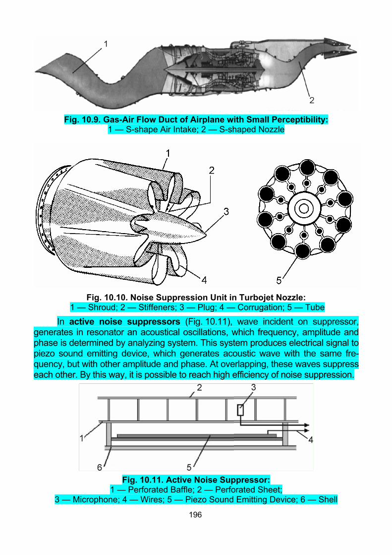
196
Fig. 10.9. Gas-Air Flow Duct of Airplane with Small Perceptibility:
1 — S-shape Air Intake; 2 — S-shaped Nozzle
Fig. 10.10. Noise Suppression Unit in Turbojet Nozzle:
1 — Shroud; 2 — Stiffeners; 3 — Plug; 4 — Corrugation; 5 — Tube
In active noise suppressors (Fig. 10.11), wave incident on suppressor, generates in resonator an acoustical oscillations, which frequency, amplitude and phase is determined by analyzing system. This system produces electrical signal to piezo sound emitting device, which generates acoustic wave with the same fre-quency, but with other amplitude and phase. At overlapping, these waves suppress each other. By this way, it is possible to reach high efficiency of noise suppression.
Fig. 10.11. Active Noise Suppressor:
1 — Perforated Baffle; 2 — Perforated Sheet; 3 — Microphone; 4 — Wires; 5 — Piezo Sound Emitting Device; 6 — Shell
197
It is necessary to keep in mind, that design measures intended for noise abatement result in increase of structural mass and growth of the engine na-celle drag, and reduce the engine thrust. Therefore, it is necessary to apply compromise settlement to economically sound application of these measures.
Checklist 1. What are exhaust units intended for? 2. List main requirements to exhaust units. 3. Which exhaust units are called nozzles? 4. List components which can be included in exhaust unit. 5. List advantages and disadvantages of subsonic nozzles with flow mix-
ing. 6. What main elements are included in subsonic nozzle with flow mixing? 7. List advantages and disadvantages of nozzles with separate exhaust. 8. Why are variable nozzles applied for supersonic flight speeds? 9. What are ejector nozzles? What are their advantages and disadvan-
tages? 10. Which versions of ejector nozzles do you know? 11. Describe flat variable supersonic nozzle. 12. What methods of thrust vectoring do you know? 13. List requirements to nozzles with thrust vectoring. 14. Describe axisymmetric nozzle with swivelling unit. 15. Describe axisymmetric nozzle with thrust vectoring in supersonic
zone. 16. What are thrust reversers intended for? 17. List main requirements to thrust reversers. 18. What are pre-exit and post-exit thrust reversers? 19. What forms of negative jet stream impact is necessary to take into ac-
count while thrust reversers designing? 20. What elements are the main sources of noise on (bypass) turbojet air-
plane? 21. What elements are the main sources of noise on turboprop airplane? 22. Characterize compressor, fan and turbine noise. 23. Characterize combustion chamber noise. 24. Characterize propeller noise. 25. Describe engine elements noise level abatement ways. 26. Which design measures of noise level abatement do you know? 27. What is sound absorbent lining? 28. What are nozzles with noise abatement? 29. What is active noise suppressor?

198
Theme 11. AIRCRAFT POWER PLANT OUTLOOK

209
Appendix. BRIEF AND FULL NAMES
OF AIRCRAFT-BUILDING AND ENGINE-BUILDING FIRMS
Aero Vironment — AeroVironment Inc., AeroVironment Incorporated (рус. Аэро Виронмент). It is a technology company. The company is probably most well-known for de-veloping a series of lightweight human-powered and then solar-powered vehicles. (Head-quarters: Monrovia, California and Simi Valley, California, USA) [34].
Aerospatiale — Aerospatiale SNI, France (рус. Аэроспасьяль) [31]. It was a French aerospace manufacturer that built both civilian and military aircraft, rockets and satellites. It was originally known as Société Nationale d'Industrie Aérospatiale (SNIAS). The company (as SNIAS) was created in 1970 by the merger of the state-owned companies Sud Aviation, Nord Aviation and Société d'études et de réalisation d'engins balistiques (SÉREB). In 1992, DaimlerBenz Aerospace AG (DASA) and Aérospatiale combined their helicopter divisions to form the Eurocopter Group. In 1999, Aérospatiale merged with Matra Haute Technologie to form Aérospatiale-Matra. In 2000, Aérospatiale-Matra merged with Construcciones Aeronáu-ticas SA (CASA) of Spain and DaimlerChrysler Aerospace AG (DASA) of Germany to form the European Aeronautic Defence and Space Company (EADS). In 2001, Aérospatiale-Matra's missile group was merged with Matra BAe Dynamics and the missile division of Alenia Marconi Systems to form MBDA [34].
Airbus — Airbus Industrie, Airbus SAS (рус. Эрбас, Эйрба́с). It is an aircraft manu-facturing subsidiary of EADS, a European aerospace company. The company produces around half of the world's jet airliners. Airbus began as a consortium of aerospace manufac-turers. Consolidation of European defence and aerospace companies around the turn of the century allowed the establishment of a simplified joint stock company in 2001, owned by EADS (80%) and BAE Systems (20%). After a protracted sales process BAE sold its share-holding to EADS in 2006. Airbus employs around 57000 people at sixteen sites in four Euro-pean Union countries: Germany, France, the United Kingdom, and Spain. Final assembly production is at Toulouse (France), Hamburg (Germany), Seville (Spain) and, since 2009, Tianjin (China). Airbus has subsidiaries in the United States, Japan and China [34]. (Head-quarters: 1 Round Point Maurice Bellonte, F-31707 Blagnac Cedex, France [33]).
Allison — Allison Gas Turbine Division (рус. Аллисон). It was a US aircraft engine manufacturer. In the mid-1970s the Allison Division of General Motors Corporation in Detroit designed ceramic components into the truck engine. Allison continued to work with General Motors on development of ceramic-turbine powered engines until the early 1990s. In 1995 was acquired by Rolls-Royce plc to become a subsidiary, Rolls-Royce Corporation. With the acquisition of Allison, Rolls-Royce expanded its product line to the point where it can now offer engines in virtually all market segments, from helicopters to the largest wide-body air-craft [34]. (Headquarters: P.O. Box 420, Indianapolis, Indiana 46206-0420, USA [33]).
ANPK MiG (АНПК МиГ) — MiG Aviation Scientific Industrial Complex (Russian: Авиационный научно-промышленный комплекс МиГ). Headquartered: Россия, Москва, Ленинградское шоссе 6 [33].
ANTK Antonov (АНТК АНТОНОВ) — Aviation Scientific-Technical Complex named for O.K. Antonov (Russian: Авиационный научно технический комплекс имени О.К. Антонова). Headquartered: Украина, Киев, ул. Академика Туполева, 1 [33].
ATLAS Elektronik — Atlas Elektronik GmbH (GmbH in Germany — Gesellschaft mit beschränkter Haftung). It is a naval/marine electronics and systems business. The company was a subsidiary of BAE Systems until 2005 when it was to ThyssenKrupp and EADS. Prior to 2003 Atlas Elektronik was part of STN Atlas Elektronik GmbH, a joint venture between Rheinmetall and BAE Systems. In 2003 the company was split; Rheinmetall acquired the

210
land systems business (Rheinmetall Defence Electronics) and BAE took control of the naval business, keeping the name Atlas Elektronik. BAE's involvement dates back to 1997 when British Aerospace (BAE Systems prior to Marconi merger) acquired 49% from Rheinmetall. (Headquarters: Bremen, Germany) [34].
AVPK Suchoi (Suchoi, АВПК Сухой) — State Unitary Enterprise Fviation Military-Industrial Complex Suchoi, which affiliate is Suchoi experimental Design Bureau JSC (Russian: Государственное унитарное предприятие авиационный военно-промышленный комплекс Сухой, в состав которого входит Опытно-конструкторское бюро Сухого АООТ). Headquartered: Россия, Москва, ул. Поликарпова 23А [33].
BAC — British Aircraft Corporation. It was a British aircraft manufacturer formed from the government-pressured merger of English Electric Aviation Ltd., Vickers-Armstrong (Air-craft), the Bristol Aeroplane Company and Hunting Aircraft in 1960. In 1977, BAC, the Hawker Siddeley Group and Scottish Aviation were nationalised and merged under the pro-visions of Aircraft and Shipbuilding Industries Act. This new group was established as a statutory corporation, British Aerospace (BAe) [31, 34].
BAe — BAe Systems plc, British Aerospace Public Ltd. It was a UK aircraft, munitions and defence-systems manufacturer. In 1999 it purchased Marconi Electronic Systems, the defence electronics and naval shipbuilding subsidiary of the General Electric Company plc, to form BAE Systems. The company was formed in the United Kingdom as a statutory corpo-ration in 1977 as a result of the Aircraft and Shipbuilding Industries Act. This called for the nationalisation and merger of the British Aircraft Corporation, Hawker Siddeley Aviation, Hawker Siddeley Dynamics and Scottish Aviation. In 1979 BAe officially joined Airbus, the UK having previously withdrawn support for the consortium in 1969 [34]. (Headquarters: Warwick House, PO Box 87, Farnborough Aerospace Centre, Farnborough, Hamspire GU14 6YU) [33].
Bell Boeing —merger of Bell Helicopter Textron, USA and the Boeing Rotorcraft Sys-tems, USA for V-22 Osprey developing and manufacturing. The Bell-Boeing V-22 Osprey is a multi-mission, military, tiltrotor aircraft with both a vertical takeoff and landing (VTOL) and short takeoff and landing (STOL) capability. It is designed to perform missions like a conven-tional helicopter with the long-range, high-speed cruise performance of a turboprop aircraft. The V-22 was developed and is built jointly by Bell Helicopter, which manufactures and inte-grates the wing, nacelles, rotors, drive system, tail surfaces, and aft ramp, as well as inte-grates the Rolls-Royce engines, and Boeing Helicopters, which manufactures and integrates the fuselage, cockpit, avionics, and flight controls. The joint development team is known as Bell Boeing. [34]. (Bell-Boeing V-22 Joint Program Office, PO Box 70, Patuxent River, Mary-land 20670-0070) [33].
Boeing Hel. — Boeing Helicopters or Boeing Helicopter Company. It is previous name of Boeing Rotorcraft Systems (before that Boeing-Vertol). It is US aircraft manufac-turer, part of Boeing Integrated Defense Systems. The factories are in Ridley Township, Pennsylvania, a suburb of Philadelphia, and Mesa, Arizona [34].
Boeing — the Boeing company (рус. Боинг). It is a US major aerospace and defense corporation. Boeing has expanded over the years, merging with McDonnell Douglas in 1997. Now it is the largest global aircraft manufacturer by revenue, orders and deliveries, and the third largest aerospace and defense contractor in the world. Boeing is the largest exporter by value in the United States [34]. (Headquarters: Seattle, Washington$ 100 North Riverside Plaza, Chicago, Illinois 60606) [33].
Convair — Consilidated Vultee Aircraft Corporation (рус. — Конвэр). It was an American aircraft manufacturing company which later expanded into rockets and spacecraft. Convair existed as a company for the design, development, and manufacturing of high-technology aerospace products, and/or sub-units of them, or else was a subsidiary of a lar-

211
ger corporation General Dynamics. Convair existed as a company from 1943 until 1994 [31, 34].
DARPA — the Defense Advanced Research Projects Agency (DARPA). It is an agency of the United States Department of Defense responsible for the development of new technology for use by the military. DARPA has been responsible for funding the development of many technologies which have had a major effect on the world, including computer net-working. Its original name was simply Advanced Research Projects Agency (ARPA), but it was renamed DARPA (for Defense) in 1972, then renamed ARPA again in 1993, and then renamed DARPA again in 1996. DARPA was established during 1958 (as ARPA) in re-sponse to the Soviet launching of Sputnik during 1957, with the mission of keeping US mili-tary technology more sophisticated than that of the nation's potential enemies. DARPA has around $3.2 billion budget. It focuses on short-term (two to four-year) projects run by small, purpose-built teams 34].
Fairchild Republic — Fairchild Republic company (рус. Фэрчайлд, Фэйрчайлд). It was an aircraft and aerospace manufacturing company. The company was founded in 1929 as Fairchild Aviation Corporation. In 1964, the company purchased Hiller Aircraft, changing its name to Fairchild Hiller. In 1965, the company acquired the Republic Aviation Company. Following the death of its founder, Fairchild changed its name to Fairchild Industries in 1971. After the company's takeover of Dornier's civil assets in 1996, the company was renamed Fairchild Dornier. In 1999 Fairchild Aerospace Corporation was acquired by German insurer Allianz A.G. and the United States investment group Clayton, Dubilier & Rice Inc. for $1.2 billion. In 2002-2003, the company was taken over by M7 Aerospace. It based at various times in Farmingdale, New York; Hagerstown, Maryland; and San Antonio, Texas [34].
General Dynamics, GD — General Dynamics Corporation (рус. Дженерал Дайнемикс). It is a US defense conglomerate formed by mergers and divestitures, and as of 2008 it is the fifth largest defense contractor in the world. The company has changed mark-edly in the post-Cold War era of defense consolidation. The company has four main busi-ness segments: Marine Systems, Combat Systems, Information Systems and Technology, and Aerospace. The company's former Fort Worth Division manufactured the F-16 Fighting Falcon, the most-produced Western jet fighter, but that subsidiary was sold to Lockheed in 1993. GD reentered the airframe business in 1999 with their purchase of Gulfstream Aero-space [31, 34].
General Electric, GE — General Electric Company (рус. Дженерал Электрик). It is a multinational American technology and services conglomerate incorporated in the State of New York. In 2009, Forbes ranked GE as the world's largest company. The company has 323,000 employees around the world. (Headquarters: Fairfield, Connecticut, USA) [31, 34].
Grumman — the Grumman Aircraft Engineering Corporation, later Grumman Aero-space Corporation (рус. Грумман) . It was a leading 20th century US producer of military and civilian aircraft. Its independent existence ended in 1994 when it was acquired by Northrop Corporation to form Northrop Grumman [31, 34].
Gulfstream — Gulfstream Aerospace Corporation, USA (рус. Гольфстрим). It is a producer of several models of jet aircraft. Gulfstream has been a unit of General Dynamics since 1999. (Headquarters: 500 Gulfstream Road, Savannah, Georgia 31408) [33].
Hawker Siddeley — Hawker Siddeley Group (рус. Хокер Сидли, Хоукер Сиддли). It was a group of British manufacturing companies engaged in aircraft production. Hawker Sid-deley combined the legacies of several British aircraft manufacturers, emerging through a series of mergers and acquisitions as one of only two such major British companies in the 1960s. In 1977, Hawker Siddeley became a founding component of the nationalised British Aerospace (BAe). The non-aviation and foreign interests were retained by a holding com-pany known as 'Hawker Siddeley Group Plc after 1980 [31, 34].
Honeywell, HON — Honeywell International Inccorporation (рус. Хоневел). It is a

212
major US conglomerate company that produces a variety of consumer products, engineering services, and aerospace systems for a wide variety of customers, from private consumers to major corporations and governments. (Headquarters: Morristown, New Jersey, USA)
Hughes Helicopter — Hughes Helicopters Incorporation (рус. Хьюз Геликоптерс). It was one of the major US manufacturers of military and civil helicopters from the 1950s to the 1980s. The company began in 1947, as a unit of Hughes Aircraft, then was part of the Hughes Tool Company after 1955. It became the Hughes Helicopter Division, Summa Cor-poration in 1972, and was reformed as Hughes Helicopters, Inc. in 1981. However, through-out its history, the company was informally known as "Hughes Helicopters". It was sold to McDonnell Douglas in 1984 and was named McDonnell Douglas Helicopter Company in 1985 [34].
Ilyushin AK (АК Ильюшина) — Aviation Complex named for S.V. ILYUSHIN (Russian: Авиационный комплекс имени С.В. Ильюшина). Headquartered: Россия, Москва, Ленинградский пр. 45г [33].
Klimov corp. (ГУНПП Климова) — the Klimov Company, the Klimov Corporation (Russian: Ленинградское научно-производственное объединение имени В.Я. Климова, later Государственное унитарное научно-производственное предприятие (ГУНПП) «Завод имени В.Я. Климова» [31]). Headquartered: Россия, г. Санкт-Петербург, ул. Кантемировская, 11 [32 ]
LHTEC — Light Helicopter Turbine Engine Company. It is a joint venture between Rolls-Royce and Honeywell. The company was originally a partnership between the Allison Engine Company and AlliedSignal Aerospace. In 1995 Rolls-Royce acquired Allison, and AlliedSignal merged with Honeywell in 1999, and adopted its name. The partnership was formed to develop the T800 turboshaft engine for the United States Army's RAH-66 Coman-che attack-reconnaissance helicopter. Despite the cancellation of this project, the company has been able to sell the T800, and its civil CTS800 model, for other helicopters [34].
Lockheed Martin, LMT — Lockheed Martin Corporation (рус. Локхид Мартин). It is US aerospace, defence, security, and advanced technology company with worldwide inter-ests. It was formed by the merger of Lockheed with Martin Marietta in 1995. Lockheed Martin is the world's largest defense contractor by revenue as $42,731 of 2008. In 2005, 95% of Lockheed Martin's revenues came from the United States Department of Defense, other US federal government agencies, and foreign military customers [34]. (Headquartered: 6801 Rockledge Drive, Bethesda, Maryland 20817) [33].
Lockheed — Lockheed Corporation, originally Loughead Aircraft Manufacturing Company (рус. Локхид). It was an American aerospace company founded in 1912 which merged with Martin Marietta in 1995 to form Lockheed Martin Corporation [31, 34].
McDonnell-Douglas — McDonnell Douglas Corporation (рус. МакДоннел-Дуглас). It was a major American aerospace manufacturer and defense contractor, producing a number of famous commercial and military aircraft. It formed from a merger of McDonnell Aircraft and Douglas Aircraft in 1967. McDonnell Douglas later merged with its rival Boeing in 1997 in a $13 billion stock-swap to create the Boeing Company (ref.).
Mil MVZ (МВЗ Миля) — Moscow Helicopter Plant named for M.L. Mil JSC (Russian: Московский вертолетный завод имени М.Л. Миля, ОАО). Headquartered: Россия, Москва, ул. Сокольнический вал, 2 [33].
MKB Raduga (МКБ «Радуга») — MKB Raduga (Russian: МКБ Радуга, meaning Raduga Design Bureau, where «raduga» literally means «rainbow»). It was formerly a divi-sion of the Mikoyan-Gurevich design bureau, before being spun off as a separate OKB (de-sign bureau) in 1957. Headquartered: Россия, Московская обл., г. Дубна [34].
NII PFM «KhAI» (НИИ ПФМ «ХАИ») — Interbranch Research Institute of Physical Simulation Problems of Aircraft Critical Flight Modes of National Aerospace University named for N.E. Zhukovsky «Kharkov Aviation institute» (Russian: Межотраслевой научно-

213
исследовательский институт проблем физического моделирования режимов полета самолетов Национального аэрокосмического университета имени Н.Е. Жуковского «Харьковский авиационный институт» (Headquartered: Украина, Харьков, ул. Чкалова 17).
North American — North American Aviation (рус. Норт Аме́рикан, Норт Аме́рикан Эвиэ́йшн). It was a major US aerospace manufacturer, responsible for a number of historic aircraft, including XB-70 strategic bomber, the X-15 rocket plane, Apollo Command and Ser-vice Module, the second stage of the Saturn V rocket, the Space Shuttle orbiter and the B-1 Lancer. Through a series of mergers and sales, North American Aviation is now part of Boeing. In December 1996, the defense and space divisions of Rockwell International (in-cluding the North American Aviation divisions Autonetics and Rocketdyne) were sold to Boeing, which integrated the product lines into their Integrated Defense Systems division. Rocketdyne was eventually sold by Boeing to UTC Pratt & Whitney, in 2005 [34].
Northrop Grumman — Northrop Grumman Corporation (рус. Нортроп-Грумман). It is an American aerospace and defence technology company formed in 1994 purchase of Grumman by Northrop. The company was the fourth largest defence contractor in the world in 2008, and the largest builder of naval vessels. (Headquartered (Headquartered: 1840 Century Perk East, Los Angeles, California 90067-2199, but in 2010 it announced plans to move to the Washington D.C. region by 2011) [33, 34].
Northrop — the Northrop Corporation (рус. Нортроп). It was a leading United States aircraft manufacturer from its formation in 1939 until 1994. The company is known for its de-velopment of the flying wing aircraft, although only a few of these have entered service. In 1994, partly due to the loss of the Advanced Tactical Fighter contract to Lockheed Martin and the removal of their proposal from consideration for the Joint Strike Fighter competition, the company bought Grumman to form Northrop Grumman [33, 34].
PMKB (ПМКБ) — Soloviev Design Bureau, Aviadvigatel & Perm Engine Company (Russian: OKB-19, later Пермское моторостроительное конструкторское бюро led by Pavel Aleksandrovich Soloviev. Following the collapse of the Soviet Union, the bureau be-came part of Компании Авиадвигатель). Headquartered: Россия, г. Пермь [31, 34].
Pratt & Whitney (P&W, Пратт энд Уитни) — United Technologies Pratt and Whit-ney Company (рус. Пратт энд Уитни). It is an American aircraft engine manufacturer of products widely used in both civil and military aircraft. As one of the «big three» aero-engine manufacturers, it competes with General Electric and Rolls-Royce, although it has also formed joint ventures with both of these companies. In addition to aircraft engines, Pratt & Whitney manufactures gas turbines for industrial and power generation, marine turbines, and rocket engines. The company support more than 9000 customers in 180 countries around the world. (Headquartered: Flhtc 400 Main St., East Hartford, CT 06108, USA) [32, 34].
Progress, ZMKB Progress («Прогресс», ЗМКБ «Прогресс») — Ivchenko-Progress ZMKB, Zaporizhia Machine-Building Design Bureau Progress State Enterprise named after Academician O.H. Ivchenko (Russian: ОКБ-478, later Государственное предприятие «Запорожское машиностроительное конструкторское бюро «Прогресс» имени академика А.Г. Ивченко»), (Ukrainian: Запорізьке машинобудівне конструкторське бюро «Прогрес» ім. О.Г. Івченка). It is a Ukrainian design house for aircraft engines whose products are widely used in both civil and military aircraft, most nota-bly by Antonov, Ilyushin, Tupolev, Mil and Yakovlev, PZL-Mielec. Both the largest plane in the world, the An-225 and the largest helicopter, the Mi-26 are powered by Lotarev engines. Headquartered: Украина, г. Запорожье, ул. Иванова, 2 [32, 33].
Rockwell — Rockwell International Corporation (рус. Рокуэлл, Роквел). It was a ma-jor American manufacturing conglomerate in the latter half of the 20th century. It was the ul-timate incarnation of a series of companies under the sphere of influence of Willard Rock-well. At the end of the 1980s, the company sold its valve and meter division (formerly Rock-

214
well Mfg.) to British Tire and Rubber. It also sold its printing press division to an internal management team. Following the «peace dividend» and the fall of the Soviet bloc, the com-pany sold its defense and aerospace business (including what was once North American Aviation and Rocketdyne) to Boeing Integrated Defense Systems in 1996. In 2001, what re-mained of Rockwell International was split into two companies: Rockwell Automation and Rockwell Collins, both publicly traded companies [31, 34].
Rolls-Royce, RR — Rolls-Royce plc. (рус. Роллс-Ройс). It is a British aircraft engine maker, and the largest in the world. The company has related businesses in the defence aerospace, marine and energy markets. Rolls-Royce was nationalised in 1971, by which time aircraft engines had long been the most significant part of the business (the automobile company was separated in 1973 as Rolls-Royce Motors). Rolls-Royce The present Rolls-Royce plc was re-privatised in 1987. (Headquartered: Derby, England, United Kingdom) [34].
Rybinsk, Rybinsk motors (ОАО РМ) — Rybinsk Motors, public corporation (Russian: Открытое акционерное общество «Рыбинские моторы»). Rybinsk Motors was created by the merger of Rybinsk Motor-Building Design Bureau RKBM and Motor-Building Plant in 1970. Headquartered: Россия, г. Рыбинск Ярославской обл., пр-т Ленина, 163 [32, 33]
Saturn, Lyulka-Saturn, (САТУРН, Люлька-САТУРН) — NPO Saturn (Russian: Научно-производственное объединение «САТУРН» [31], later Открытое акционерное общество (ОАО) «А. Люлька-САТУРН»). Headquartered: Россия, Москва, ул. Касаткина, 13 [32, 33]
Sikorsky — Sikorsky Aircraft Corporation (рус. Сикорский). It s an American aircraft (mainly helicopter) manufacturer. In 1929 the company became a part of United Aircraft and Transport Corporation (now United Technologies Corporation) [34]. (Headquartered: 6900 Main Street, Stratford, Connecticut 06615-9129) [33].
SNECMA (рус. СНЕКМА) — an acronym for Société Nationale d'Étude et de Con-struction de Moteurs d'Aviation (in English, «National Company for the Design and Construc-tion of Aviation Engines»). It is a major French manufacturer of engines for commercial and military aircraft, and for space vehicles. In 2005, the Snecma group, which included Snecma (called Snecma Moteurs at this time), merged with SAGEM to form SAFRAN. Snecma is now a subsidiary of the SAFRAN Group and previous Snecma group subsidiaries have been reorganised within the wider group [34].
Soyuz, Soyuz AMNTK («Союз», АМНТК «Союз») — Aviamotors Scientific-Technical Complex «Soyuz», public corporation (Russian: Открытое акционерное общество Авиамоторный научно-технический комплекс «Союз»). Headquartered: Россия, г. Москва, Лужнецкая наб., 2/4 [32, 33].
Teledyne Ryan — Teledyne Ryan Aeronautical (USA). The Ryan Aeronautical Com-pany was founded by T. Claude Ryan in 1934. It produced many airplanes over the years, most of them trainers. T. Claude Ryan sold Ryan Aeronautical Corp. to the Teledyne Corpo-ration in 1969. It produced a series of pilotless drones and airframes for the Bell Huey heli-copter. Northrop Grumman purchased Teledyne Ryan in 1999 [34].
Tupolev ANTK (АНТК Туполев) — Aviation Scientific-Technical Complex named for A.N. Tupolev, JSC (Russian: Авиационный научно технический комплекс имени А.Н. Туполева, открытое акционерное общество). Headquartered: Россия, Москва, наб. Академика Туполева, 17 [33].
Williams Research — Williams Research Corporation, later Williams Internationa Corporation. It has been building small turbofan engines since the 1950s for use in cruise missiles, target, reconnaissance drones and small jet-powered aircraft. Using the missile en-gines, Williams developed a series of personal VTOL flying craft, including a jet-powered belt in 1969, the Williams Aerial Systems Platform (WASP), also known as the «flying pulpit» in

215
the 1970s, and the X-Jet, which was evaluated by the United States Army in the 1980s. (Headquartered: Walled Lake, Michigan, United States [34].
Yakovlev OKB (ОКБ Яковлева) — Experimental Design Bureau named for A.S. Yakovlev JSC (Russian: Опытно-конструкторское бюро имени А.С. Яковлева). Headquartered: Россия, Москва, Ленинградский пр., 68 [33].

216
BIBLIOGRAPHY
1. Kroes, M. J. Aircraft Power Plants [Text] / M. J. Kroes, T. W. Wild, 7th edition. — Singapore : McGraw–Hill Book Co., 1994. — 694 p.
2. Kroes, M. J. Aircraft maintenance and repair [Text] / M. J. Kroes, W. A. Watkins, F. Delp, 6th edition. — Singapore : McGraw–Hill Book Co., 1993. — 648 p.
3. Василевский, Е. Т. Основные положения воздушного кодекса Ук-раины и норм лётной годности самолётов транспортной категории [Текст] : учеб. пособие / Е. Т. Василевский, В. А. Гребеников, В. Н. Николаенко. — Х. : Нац. аэрокосм. ун-т «Харьк. авиац. ин-т», 2006. — 332 с.
4. Нормы лётной годности гражданских самолётов СССР (НЛГС-3) [Текст]. — 3-е изд. — М., 1985. — 470 с.
5. Югов, О. К. Основы интеграции самолёта и двигателя [Текст] / О. К. Югов, О. Д. Селиванов; под общ. ред. О. К. Югова. — М. : Машино-строение, 1989. — 304 с.
6. Околота, Н. В. Обозначение чертежей и оформление учебно-конструкторской документации [Текст] / Н. В. Околота, Б. А. Черепенников. — Х. : Харьк. авиац. ин-т, 1987. — 40 с.
7. Шульженко, М. Н. Конструкция самолётов [Текст] / М. Н. Шульженко. — М. : Машиностроение, 1971. — 416 с.
8. Житомирский, Г. И. Конструкция самолетов [Текст] : учеб. для студентов авиац. спец. вузов / Г. И. Житомирский. — М. : Машинострое-ние, 1991. — 400 с.
9. Авиационные силовые установки. Системы и устройства [Текст] / Н. Т. Доматенко, А. С. Кравец, Г. А. Никитин, А. И. Пугачёв. — М. : Транс-порт, 1976. — 312 с.
10. Доматенко, Н. Т. Авиационные силовые установки [Текст] / Н. Т. Доматенко, А. С. Кравец. — М. : Транспорт, 1970. — 352 с.
11. Поликовский, В. И. Силовые установки летательных аппаратов с воздушно-реактивными двигателями [Текст] / В. И. Поликовский, Д. Н. Сурнов. — М. : Машиностроение, 1965. — 261 с.
12. Лещинер, Л. Б. Проектирование топливных систем самолётов [Текст] / Л. Б. Лещинер, И. Е. Ульянов. — М. : Машиностроение, 1975. — 343 с.
13. Павленко, В. Ф. Силовые установки летательных аппаратов вер-тикального взлёта и посадки [Текст] / В. Ф. Павленко. — М. : Машино-строение, 1972. — 284 с.
14. Никифоров, Г. Н. Конструкция самолётных агрегатов [Текст] : учеб. для авиац. техникумов / Г. Н. Никифоров, Г. В. Копылев. — М. : Ма-шиностроение, 1989. — 248 с.
15. Лебединский, А. Г. Компоновка силовых установок самолётов [Текст] : консп. лекций по курсу «Силовые установки самолётов» / А. Г. Лебединский. — Х. : Харьк. авиац. ин-т, 1983. — 88 с.

217
16. Лебединский, А. Г. Системы крепления двигателей на самолёте [Текст] : консп. лекций по курсу «Силовые установки самолётов» / А. Г. Лебединский. — Х. : Харьк. авиац. ин-т, 1980. — 32 с.
17. Дыбский, П. В. Топливные системы [Текст] : консп. лекций по кур-су «Силовые установки самолётов» / П. В. Дыбский, В. Д. Пехтерев. — Х. : Харьк. авиац. ин-т, 1976. — 43 с.
18. Пехтерев, В. Д. Масляные системы самолётов [Текст] : консп. лекций по курсу «Силовые установки самолётов» / В. Д. Пехтерев. — Х. : Харьк. авиац. ин-т, 1973. — 43 с.
19. Данильченко, К. П. Воздухозаборники самолётов [Текст] : учеб. пособие по курс. и дипл. проектированию / К. П. Данильченко, А. Г. Лебединский. — Х. : Харьк. авиац. ин-т, 1984. — 56 с.
20. Кобылянский, А. А. Характеристики газотурбинных двигателей [Текст] : учеб. пособие / А. А. Кобылянский, А. Г. Гребеников. — Х. : Харьк. авиац. ин-т, 1984. — 56 с.
21. Лебединский, А. Г. Методические указания к выполнению курсово-го проекта по курсу «Проектирование силовых установок и систем самолё-тов» [Текст] / А. Г. Лебединский. — Х. : Харьк. авиац. ин-т, 1987. — 36 с.
22. Синькевич, М. В. Автоматизированное проектирование деталей, узлов и агрегатов самолёта [Текст] : учеб. пособие / М. В. Синькевич, Л. А. Малашенко, П. В. Балабуев. — Х. : Харьк. авиац. ин-т, 1992. — 56 с.
23. Лебединский, А. Г. Силовые установки самолётов [Текст] : учеб. пособие по курс. и дипл. проектированию / А. Г. Лебединский, В. Д. Пехтерев, В. Н. Желдоченко. — Х. : Харьк. авиац. ин-т, 1981. — 64 с.
24. Кривцов, В. С. Живучесть авиационных силовых установок [Текст] : учеб. для студентов вузов (направление "Авиация и космонавти-ка") / В. С. Кривцов, А. И. Рыженко. — Х. : Нац. аэрокосм. ун-т «Харьк. авиац. ин-т», 2004. — 659 с.
25. Оружие и технологии России. Энциклопедия XXI век [Текст] : в 20 т. / под общ. ред. И. Клебанова. — М. : Изд. дом «Оружие и техноло-гии», 2005. — Т. 10 : Авиационное вооружение и авионика. — 784 с.
26. Курочкин, Ф. П. Основы проектирования самолетов с вертикаль-ным взлетом и посадкой [Текст] / Ф. П. Курочкин. — М. : Машиностроение, 1970. — 352 с.
27. Курочкин, Ф. П. Проектирование и конструирование самолетов с вертикальным взлетом и посадкой [Текст] / Ф. П. Курочкин. — М. : Машиностроение, 1977. — 224 с.
28. Володин, В. В. Особенности проектирования реактивных самоле-тов вертикального взлета и посадки [Текст] / В. В. Володин, Н. К. Лисей-цев, В. З. Максимович. — М. : Машиностроение, 1985. — 224 с.
29. Хафер, К. Техника вертикального взлета и посадки [Текст] : пер. с нем. / К. Хафер, Г. Закс. — М. : Машиностроение, 1985. — 352 с.

218
30. Мороз, С. Управляемые ракеты дальней и морской авиации СССР [Текст] / С. Мороз, С. Попсуевич. — М. : Майор; ООО «Пилот», 2001. — 92 с.
31. Авиация: энциклопедия [Текст] / Большая Российская Энциклопе-дия, ЦАГИ; под ред. Г. П. Свищева. — М., 1994. — 736 с.
32. Двигатели 1944–2000: авиационные, ракетные, морские, про-мышленные: ил. электрон. справ. изд. — 3-е изд. — М. : АКС-Конверсалт, 2000. — 387 с.
33. Jane's. All The World's Aircraft. 2004-2005 England, London: Jane's Publishing Company, 2005. – 860+40 p.
34. www.wikipedia.org 35. www.airwar.ru 36. www.designation-systems.net/dusrm/m-136.html 37. Oswatitsch, K. Der Druckrueckgewinn bei Geshossen mit
Rueckstossantrieb bei hohen Ueberschallgeschwindigkeiten (Der Wirkungsgrad von Stossdiffusoren). Foschungen und Entwicklingen des Heereswaffenamters, Bericht Nr., 1005, Goettingen, January 1944.
38. Нечаев, Ю. Н. Входные устройства сверхзвуковых самолётов [Текст] / Ю. Н. Нечаев. — М. : Воениздат, 1963. — 140 с.
39. Поликовский, В. И. Самолётные силовые установки [Текст] / В. И. Поликовский. — М. : Оборонгиз, 1952. — 600 с.
40. Космонавтика: энциклопедия [Текст] / Советская энциклопедия; гл. ред. В. П. Глушко. — М., 1985. — 528 с.
41. Глаголев, А. Н. Конструкция самолётов [Текст] / А. Н. Глаголев, М. Я. Гольдинов, С. М. Григоренко. — М. : Машиностроение, 1975. — 480 с.
42. Военная авиация [Текст] : справ. / Ю. В. Гордиенко, В. П. Морозов, А. С. Прибылов; в 2 кн. — Минск : Попурри, 1999. Кн. 1. — 512 с.
43. Зайцев, В. Н. Конструкция и прочность самолётов [Текст] / В. Н. Зайцев, В. Л. Рудаков. — К. : Вища шк., 1978. — 488 с.
44. Кондратьев, В. И-185 — ставка на мощность [Текст] / В. Кондратьев // Моделист-конструктор. — 1983. — № 7. — С. 13–16.
45. Кондратьев, В. Первенцы эпохи реактивных [Текст] / В. Кондратьев // Моделист-конструктор. — 1983. — № 11. — С. 29–32.
46. Шульженко, М. Н. Сборник иллюстраций по курсу конструкций самолётов / М. Н. Шульженко. — М. : Оборонгиз, 1954. — 100 с.
47. Спортивно-пилотажный самолёт Як-55. Техническое описание [Текст]: 1987. — 156 с.
48. Пассажирский самолёт Ил-18В. Техническое описание [Текст]: в 3 кн. — М. : Машиностроение, 1964. — Кн. 3 : Силовая установка. — 123 с.
49. Gulfstream G550. Operating Manual. Power Plant, 2003. — 16 c. 50. Самолёт типа 02Б. Техническое описание [Текст]: в 2 кн. — М. :
Воениздат, 1975. — Кн. 1 : Планер и системы. — 246 с.

219
51. Самолёт Як-40. Инструкция по эксплуатации [Текст]: в 10 кн. — Кн. 3 : Силовая установка. — 264 с.
52. Самолёт Ан-124. Руководство по технической эксплуатации [Текст]: в 18 кн. / отв. ред. В. А. Сумцов. — Кн. 4 : 028.Топливная систе-ма. — 274 с.
53. Герман, Р. Сверхзвуковые входные диффузоры [Текст] / Р. Герман. — М. : Физматгиз, 1960. — 290 с.
54. Ильин, В. Первенец в четвёртом поколении [Текст] / В. Ильин // Крылья родины. — 1992. — № 1. — С. 20–23.
55. Бедретдинов, И. Ударно-разведывательный самолёт Т-4 [Текст] / И. Бедретдинов. — М. : Изд. группа «Бедретдинов и Ко», 2005. — 203 с.
56. Кривцов, В. С. Основы аэрокосмической техники [Текст] : учеб. для высш. учеб. заведений : в 2 ч. / В. С. Кривцов, Я. С. Карпов, М. Н. Федотов. — Х. : Нац. аэрокосм. ун-т «Харьк. авиац. ин-т», 2003. — Ч. 2. — 901 с.
57. Электронный ресурс http://bp-la.ru 58. Электронный ресурс http://www.darpa.mil/body/wasp_1.htm 59. Электронный ресурс http://www.aerovironment.com 60. Электронный ресурс Википедия 61. Электронный ресурс http://www.microavia.narod.ru. = реф ЕР 62. Галушка, С. Беспилотные летательные аппараты кардинально
изменят облик авиации будущего [Текст] / С. Галушка // Авиапанорама, июль-август 2005, с. 34–39.
63. Ростопчин, В. Беспилотные авиационные системы [Текст] / В. Ростопчин, С. Румянцев // Вестник Воздушного Флота. — 2001.
64. Dornheim, M.A. Unnmanned Aerial Vehicles. Several Micro Air Vehi-cles in Flight Test Programs [Text] / M.A. Dornheim // Aviation Week & Space Technology 12, 1999, p. 47–49.
65. Thomas J. Mueller (Ed.), ed (2002). Fixed and Flapping Wing Aerody-namics for Micro Air Vehicle Applications. AIAA. ISBN 1-56347-517-0. http://www.amazon.com/dp/1563475170/.
66. Кейси, Э.Э. Великий ясновидящий Эдгар Кейси об Атлантиде [Текст] / Э. Э. Кейси. — М. : Новый Центр, 2000. — 175 с.
67. Peter Forbes, The Gecko's Foot: How Scientists are Taking a Leaf from Nature's Book, Harper Perennial, 2006, p. 161–179.
68. Кривов, Г.А. Мировая авиация на рубеже XX–XXI столетий. Про-мышленность, рынки [Текст] / Г. А. Кривов, В. А. Матвиенко, Л. Ф. Афанасьева — К. : 2003. — 296 с.
69. Василин, Н.Я. Беспилотные летательные аппараты [Текст] / Н. Я. Василин. — Минск : Попурри, 2003. — 272 с.
70. Общие виды и характеристики беспилотных летательных аппара-тов [Текст] : справ. пособие / А. Г. Гребеников, А. К. Мялица, В. В. Парфенюк и др. — Х. : Нац. аэрокосм. ун-т «Харьк. авиац. ин-т», 2008. – 377 с.

220
71. Иноземцев, А. А. Газотурбинные двигатели [Текст] / А. А. Иноземцев, В. Л. Сандрацкий. — Пермь: ОАО «Авиадвигатель», 2006. — 1202 с.
72. Куликов, А. А. Практическая аэродинамика самолёта МиГ-25 [Текст] / А. А. Куликов. — М. : Воениздат, 1978. — 320 с.
73. Самолёт Ан-26. Техническое описание [Текст]: в ? кн. — М. : Авиаэкспорт. — Кн. 2 : Конструкция самолёта. — 303 с.
74. United States Patent No. 6607165 B1. Aircraft Engine Mount with Single Thrust Link / John Alan Manteiga, Christopher James Wilusz, Cornelius Harm Dykhuizen; Assignee: General Electric Company. — Appl. No. 1/185922; Filed Jun. 28, 2002, Published Aug. 19, 2003. — 9 p.
75. United States Patent No. 4044973. Nacelle Assembly and Mounting Structures for a Turbofan Jet Propulsion Engine / James R. Moorehead; As-signee: The Boeing Company. — Appl. No. 644915; Filed Dec. 29, 1975; Pub-lished Aug. 30, 1977. — 24 p.
76. Штехер, М. С. Топлива и рабочие тела ракетных двигателей [Текст]: учеб. пособие для авиац. вузов / М. С. Штехер. — М. : Машино-строение, 1976. — 304 с.
77. Пассжирский самолёт Ил-62 [Текст]: в 2 ч. — М. : Машинострое-ние, 1981. — Ч. 1 : Характеристики самолёта, конструкция планера, сис-темы самолёта — 359 с.
78. Самолёт Ил-62. Инструкция по технической эксплуатации. [Текст] — М. : Машиностроение, 1968 — 152 с.
79. Самолёт Ту-134. Инструкция по эксплуатации [Текст]: в 7 кн. — М. : ОКБ им. Туполева. — Кн. 3: Силовая установка, 1968.
80. Физико-химические и эксплуатационные свойства реактивных то-плив: Справочник [Текст] / Н. Ф. Дубровкин, В. Г. Маланичева, Ю. П. Массур, Е. П. Федоров — М. : Химия, 1985. — 240 с.
81. Техническое описание пассажирского самолёта «Ту-104» [Текст]: в 10 кн. — М. : ОКБ им. Туполева. — Кн. 5: Силовая установка, 1955. — 166 с.
82. Альбом конструкций самолёта МиГ-15 с двигателем ВК-1, М. : Воениздат, 1951. — 127 с.
83. Самолёт МиГ-15 [Текст]: М. : Оборонгиз, 1949 — 183 с. 84. Самолёт МиГ-19. Инструкция по эксплуатации и техническому об-
служиванию [Текст]: М. : Оборонгиз, 1957 — 208 с. 85. Самолёт МиГ-21Ф-13. Техническое описание [Тескт]: в 3 кн. —
М. : Оборонгиз, 1964. — 219 с. 86. Изделие 23-11. Краткое описание и временная инструкция по
технической эксплуатации [Текст]: в 4 кн. — М. : Воениздат. — Кн. 1. Са-молёт и его системы в 3 ч. Ч. 2. Силовая установка, управление двигате-лем, управление клиньями воздухозаборников, топливная система, проти-вопожарное оборудование. 1971, — 123 с.
87. Самолёт Ту-144 в 5 альбомах. Альбом 2. «Силовая установка. Противопожарное оборудование». ВАЗ, 1975. — 41 с.

221
88. Самолёт Ан-22. Техническое описание [Текст]: в 9 кн. — Кн. 3. Силовая установка. К. : ОКБ им. О. К. Антонова, 1970, — 160 с.
89. Самолёт Ан-72. Руководство по технической эксплуатации [Текст]: в 15 кн. — Кн. 6. Гондолы двигателя. Силовая установка. К. : ОКБ им. О. К. Антонова, 1984.

222
CONTENT PREFACE.................................................................................................3
Theme 1. INTRODUCTION TO COURSE «AIRCRAFT POWER
PLANT SYSTEMS DESIGNING» .............................................................5
Theme 2. CLASSIFICATION OF POWER PLANTS. TYPES OF
AIRCRAFT ENGINES AND THEIR ARRANGEMENT ON AIRCRAFT ....9
Theme 3. NACELLES AND COWLINGS OF ENGINES. ENGINE
MOUNT...................................................................................................33
Theme 4. VIBRATIONS OF POWER PLANTS. SHOCK–
ABSORPTION OF ENGINE MOUNT .....................................................89
Theme 5. FUEL SYSTEMS OF POWER PLANT ...................................99
Theme 6. LUBRICATION SYSTEMS OF POWER PLANTS................140
Theme 7. INTERNAL AERODYNAMICS OF POWER PLANTS ..........157
Theme 8. AIR SUCTION SYSTEM. SUBSONIC INLETS ....................162
Theme 9. SUPERSONIC AIR INTAKES...............................................170
Theme 10. EXHAUST UNITS OF POWER PLANTS ...........................186
Theme 11. AIRCRAFT POWER PLANT OUTLOOK ............................198
Appendix. BRIEF AND FULL NAMES OF AIRCRAFT-BUILDING AND
ENGINE-BUILDING FIRMS..................................................................209
BIBLIOGRAPHY ...................................................................................216

Shmyrov Vladimir Fedorovich Tsukanov Ruslan Urievich
Ryzhenko Alexandr Ivanovich Pehterev Valentin Dmitrievich
Шмирьов Володимир Федорович
Цуканов Руслан Юрійович Риженко Олександр Іванович Пехтєрєв Валентин Дмитрович
AIRPLANE POWER PLANTS SYSTEMS DESIGNING
ПРОЕКТУВАННЯ СИСТЕМ СИЛОВИХ УСТАНОВОК ЛІТАКІВ
Переклад: Р. Ю. Цуканов, О. І. Риженко
Редактори: Т. А. Ястремська, М. В. Кириленко, Н. С. Дорошенко
Технічний редактор: Л. О. Кузьменко
Комп’ютерна верстка: Р. Ю. Цуканов
Зв. план, 2010 Підписано до друку 29.01.2010 Формат 60×84 1/16. Папір офс. № 2. Офс. друк Ум. друк. арк. 12,3. Обл.-вид. арк. 13,81. Наклад 200 прим. Замовлення 32. Ціна вільна
Національний аерокосмічний університет ім. М. Є. Жуковського
« Х а р к і в с ь к и й а в і а ц і й н и й і н с т и т у т » 61070, Харків-70, вул. Чкалова, 17
http://www.khai.edu Видавничий центр «ХАІ»
61070, Харків-70, вул. Чкалова, 17 [email protected]