akj series 9 rohs-compliant series rs232c communications cable monitor harness for oil cooler units...
TRANSCRIPT

上海分公司(Shanghai Branch)DAIKIN HYDRAULICS (SUZHOU) CO., LTD.
◎
◎
◎
大連分公司(Dalian Branch)DAIKIN HYDRAULICS (SUZHOU) CO., LTD.◎
北京営業所(Beijing Office)DAIKIN HYDRAULICS (SUZHOU) CO., LTD.◎
広州営業所(Guangzhou Office)DAIKIN HYDRAULICS (SUZHOU) CO., LTD.◎
瀋陽営業所(Shenyang Office)DAIKIN HYDRAULICS (SUZHOU) CO., LTD.◎
◎
KD HYDRAULICS,LTD.
HO TAI DEVELOPMENT CO.,LTD.
SIAM DAIKIN SALES CO., LTD.
ZICOM PRIVATE LTD.
DAIKIN AIR CONDITIONING INDIA PVT.LTDDELHI BRANCH
ALL WORLD MACHINERY
Please contact Daikin Sales Counter for servicing of Oil Cooling Unit in countries outside Japan.
Country/Region Company name
◎Sales agents of hydraulic equipment.Others are the sales agent of air conditioning equipment.
(As of Oct. 30, 2015)
Locations
Overseas service network
China
Korea
Taiwan
Thailand
Singapore
India
U.S.
Beijing
Shanghai
Dalian
Guangzhou
Shenyang
Seoul
Taipei
Singapore
Bangkok
New Delhi
Illinois
Daikin is ready to offer you service in conjunction with the sales agents of our Air-conditioning and Hydraulic Divisions located in seven countries and regions worldwide.
AKJ9 SERIES
AKC9 SERIES
GK248 (2015.10.020) DF.MD.MD●Contents in this catalog are subject to change for improvement without prior notice.
Circulating type
Immersion type
Oil Hydraulic Division
Oil Hydraulic Equipment
9AKJAKC
SERIES
Osaka OfficeYODOGAWA PLANT1-1, Nishi-Hitotsuya, Settsu, Osaka 566-8585, Japan
Home Page: http://www.daikinpmc.com/en/
AKJ9 SERIESCirculating typeImmersion type
9AKJAKC
SERIES
AKC9 SERIESAKJ9 SERIES AKC9 SERIES
Oil Hydraulic Division
I N D E XAKJ9 SERIES (Immersion type)
Overview / Features
System OverviewPiping System Diagram
Nomenclature
Specifications and Operating range
Cooling Capacity Characteristic Chart
External Dimension Diagram
Installation Dimension Diagram
Pages 1 to 2
Pages 3
Pages 4
Pages 5 to 6
Pages 7 to 8
Pages 9 to 11
Pages 12
AKC9 SERIES (Circulating type)
Pages 13
Pages 13
Pages 14
Pages 14
Pages 15
Pages 15
Pages 15
Pages 16
Overview/Features
System Configuration
Optional Parts
Pages 17
Pages 18
Thermistor
Extension board for main machine communication
Nomenclature
Specifications
Cooling Capacity Characteristic Chart
Internal Pressure Loss
External Dimension Diagram
Flow Rate Characteristics for Models With a Pump
Supporting Information
Pages 19
Pages 20
Pages 21 to 22
Pages 23
Pages 24 to 25
Pages 26
Control Panel
Operation Mode/Setting Method
Electric Schematic Diagram
Electric Wiring Connection Instruction Diagram
Notes for handling
Method of selection of Oil Cooling Unit
21
Overview / Features
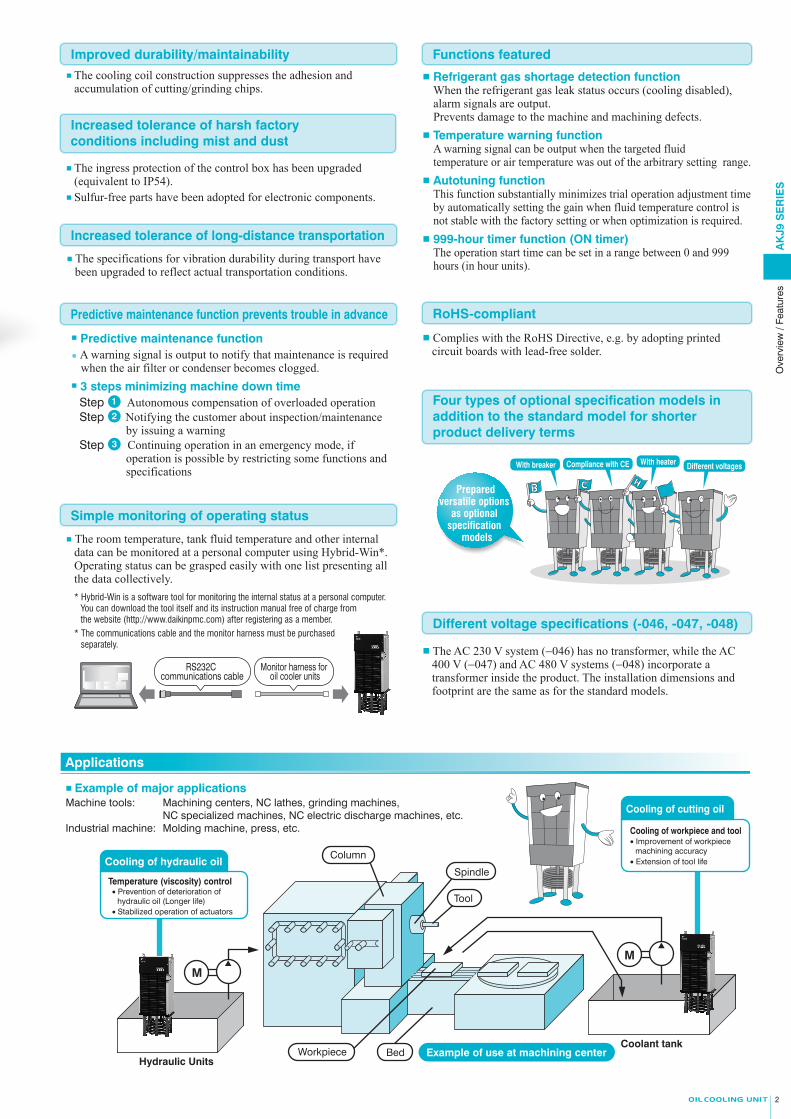
Cooling of workpiece and tool
Cooling of cutting oil
• Improvement of workpiece machining accuracy
■ The specifications for vibration durability during transport have been upgraded to reflect actual transportation conditions.
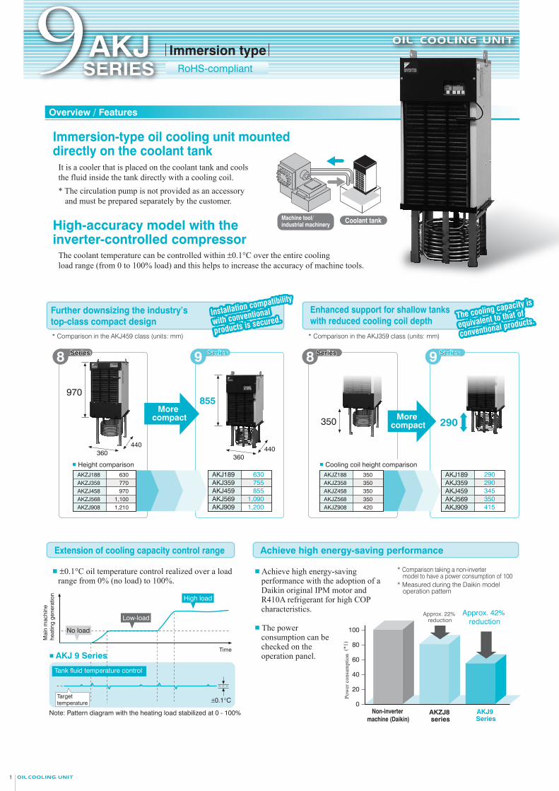
■ ±0.1°C oil temperature control realized over a load range from 0% (no load) to 100%.
Further downsizing the industry’s top-class compact design
Enhanced support for shallow tanks with reduced cooling coil depth
Increased tolerance of harsh factory conditions including mist and dust
■ Predictive maintenance function● A warning signal is output to notify that maintenance is required
when the air filter or condenser becomes clogged.■ 3 steps minimizing machine down time
Step ● Autonomous compensation of overloaded operationStep ● Notifying the customer about inspection/maintenance
by issuing a warningStep ● Continuing operation in an emergency mode, if
operation is possible by restricting some functions and specifications
■ The room temperature, tank fluid temperature and other internal data can be monitored at a personal computer using Hybrid-Win*.Operating status can be grasped easily with one list presenting all the data collectively.
Mai
n m
achi
ne
heat
ing
gene
ratio
n
Time
Note: Pattern diagram with the heating load stabilized at 0 - 100%
Low-load
High load
Tank fluid temperature control
±0.1°C
■ AKJ 9 Series
Prepared versatile options
as optional specification
models
■ The ingress protection of the control box has been upgraded (equivalent to IP54).
■ Sulfur-free parts have been adopted for electronic components.
No load
Target temperature
100
80
60
40
20
0
Pow
er c
onsu
mpt
ion
Non-inverter machine (Daikin)
AKZJ8 series
AKJ9 Series
Approx. 42% reduction
Approx. 22% reduction
Example of use at machining center
Temperature (viscosity) control
Cooling of hydraulic oil
• Prevention of deterioration of hydraulic oil (Longer life)
Hydraulic Units
Coolant tank
MM
Workpiece Bed
Tool
Spindle
3
Coolant tankMachine tool/industrial machinery
8 Series
* Comparison in the AKJ459 class (units: mm) * Comparison in the AKJ359 class (units: mm)
855
360440
More compact More
compact
630770970
1,1001,210
AKZJ188AKZJ358AKZJ458AKZJ568AKZJ908
AKJ189AKJ359AKJ459AKJ569AKJ909
630755855
1,0901,200
350 290
AKJZ188 350AKJZ358 350AKJZ458 350AKJZ568 350AKJZ908 420
AKJ189AKJ359AKJ459AKJ569AKJ909
290290345350415
■ Height comparison ■ Cooling coil height comparison
970
360440
With breaker Different voltagesCompliance with CE With heater
Immersion typeRoHS-compliant9AKJ
SERIES
RS232C communications cable
Monitor harness for oil cooler units
Improved durability/maintainability
Increased tolerance of long-distance transportation
Predictive maintenance function prevents trouble in advance
Simple monitoring of operating status
Functions featured
RoHS-compliant
Different voltage specifications (-046, -047, -048)
ApplicationsExtension of cooling capacity control range Achieve high energy-saving performance
Series 8 SeriesSeries9 SeriesSeries 9 SeriesSeries
Column
It is a cooler that is placed on the coolant tank and cools the fluid inside the tank directly with a cooling coil.* The circulation pump is not provided as an accessory
and must be prepared separately by the customer.
High-accuracy model with the inverter-controlled compressor
The coolant temperature can be controlled within ±0.1°C over the entire cooling load range (from 0 to 100% load) and this helps to increase the accuracy of machine tools.
(*1)
■ The cooling coil construction suppresses the adhesion and accumulation of cutting/grinding chips.
■ Refrigerant gas shortage detection functionWhen the refrigerant gas leak status occurs (cooling disabled), alarm signals are output.Prevents damage to the machine and machining defects.
■ Temperature warning functionA warning signal can be output when the targeted fluid temperature or air temperature was out of the arbitrary setting range.
■ Autotuning functionThis function substantially minimizes trial operation adjustment time by automatically setting the gain when fluid temperature control is not stable with the factory setting or when optimization is required.
■ 999-hour timer function (ON timer)The operation start time can be set in a range between 0 and 999 hours (in hour units).
■ Complies with the RoHS Directive, e.g. by adopting printed circuit boards with lead-free solder.
■ The AC 230 V system (−046) has no transformer, while the AC 400 V (−047) and AC 480 V systems (−048) incorporate a transformer inside the product. The installation dimensions and footprint are the same as for the standard models.
1
2
3
• Stabilized operation of actuators
• Extension of tool life
Immersion-type oil cooling unit mounted directly on the coolant tank
Installation compatibility
with conventional
products is secured.Installation compatibility
with conventional
products is secured. The cooling capacity is
equivalent to that of
conventional products.The cooling capacity is
equivalent to that of
conventional products.
■ The power consumption can be checked on the operation panel.
■ Achieve high energy-saving performance with the adoption of a Daikin original IPM motor and R410A refrigerant for high COP characteristics.
* Comparison taking a non-inverter model to have a power consumption of 100
* Measured during the Daikin model operation pattern
* Hybrid-Win is a software tool for monitoring the internal status at a personal computer. You can download the tool itself and its instruction manual free of charge from the website (http://www.daikinpmc.com) after registering as a member.
* The communications cable and the monitor harness must be purchased separately.
Four types of optional specification models in addition to the standard model for shorter product delivery terms
■ Example of major applicationsMachine tools: Machining centers, NC lathes, grinding machines, NC specialized machines, NC electric discharge machines, etc.Industrial machine: Molding machine, press, etc.
AK
J9 S
ER
IES
Ove
rvie
w /
Feat
ures
21
Overview / Features
Cooling of workpiece and tool
Cooling of cutting oil
• Improvement of workpiece machining accuracy
■ The specifications for vibration durability during transport have been upgraded to reflect actual transportation conditions.
■ ±0.1°C oil temperature control realized over a load range from 0% (no load) to 100%.
Further downsizing the industry’s top-class compact design
Enhanced support for shallow tanks with reduced cooling coil depth
Increased tolerance of harsh factory conditions including mist and dust
■ Predictive maintenance function● A warning signal is output to notify that maintenance is required
when the air filter or condenser becomes clogged.■ 3 steps minimizing machine down time
Step ● Autonomous compensation of overloaded operationStep ● Notifying the customer about inspection/maintenance
by issuing a warningStep ● Continuing operation in an emergency mode, if
operation is possible by restricting some functions and specifications
■ The room temperature, tank fluid temperature and other internal data can be monitored at a personal computer using Hybrid-Win*.Operating status can be grasped easily with one list presenting all the data collectively.
Mai
n m
achi
ne
heat
ing
gene
ratio
n
Time
Note: Pattern diagram with the heating load stabilized at 0 - 100%
Low-load
High load
Tank fluid temperature control
±0.1°C
■ AKJ 9 Series
Prepared versatile options
as optional specification
models
■ The ingress protection of the control box has been upgraded (equivalent to IP54).
■ Sulfur-free parts have been adopted for electronic components.
No load
Target temperature
100
80
60
40
20
0
Pow
er c
onsu
mpt
ion
Non-inverter machine (Daikin)
AKZJ8 series
AKJ9 Series
Approx. 42% reduction
Approx. 22% reduction
Example of use at machining center
Temperature (viscosity) control
Cooling of hydraulic oil
• Prevention of deterioration of hydraulic oil (Longer life)
Hydraulic Units
Coolant tank
MM
Workpiece Bed
Tool
Spindle
3
Coolant tankMachine tool/industrial machinery
8 Series
* Comparison in the AKJ459 class (units: mm) * Comparison in the AKJ359 class (units: mm)
855
360440
More compact More
compact
630770970
1,1001,210
AKZJ188AKZJ358AKZJ458AKZJ568AKZJ908
AKJ189AKJ359AKJ459AKJ569AKJ909
630755855
1,0901,200
350 290
AKJZ188 350AKJZ358 350AKJZ458 350AKJZ568 350AKJZ908 420
AKJ189AKJ359AKJ459AKJ569AKJ909
290290345350415
■ Height comparison ■ Cooling coil height comparison
970
360440
With breaker Different voltagesCompliance with CE With heater
Immersion typeRoHS-compliant9AKJ
SERIES
RS232C communications cable
Monitor harness for oil cooler units
Improved durability/maintainability
Increased tolerance of long-distance transportation
Predictive maintenance function prevents trouble in advance
Simple monitoring of operating status
Functions featured
RoHS-compliant
Different voltage specifications (-046, -047, -048)
ApplicationsExtension of cooling capacity control range Achieve high energy-saving performance
Series 8 SeriesSeries9 SeriesSeries 9 SeriesSeries
Column
It is a cooler that is placed on the coolant tank and cools the fluid inside the tank directly with a cooling coil.* The circulation pump is not provided as an accessory
and must be prepared separately by the customer.
High-accuracy model with the inverter-controlled compressor
The coolant temperature can be controlled within ±0.1°C over the entire cooling load range (from 0 to 100% load) and this helps to increase the accuracy of machine tools.
(*1)
■ The cooling coil construction suppresses the adhesion and accumulation of cutting/grinding chips.
■ Refrigerant gas shortage detection functionWhen the refrigerant gas leak status occurs (cooling disabled), alarm signals are output.Prevents damage to the machine and machining defects.
■ Temperature warning functionA warning signal can be output when the targeted fluid temperature or air temperature was out of the arbitrary setting range.
■ Autotuning functionThis function substantially minimizes trial operation adjustment time by automatically setting the gain when fluid temperature control is not stable with the factory setting or when optimization is required.
■ 999-hour timer function (ON timer)The operation start time can be set in a range between 0 and 999 hours (in hour units).
■ Complies with the RoHS Directive, e.g. by adopting printed circuit boards with lead-free solder.
■ The AC 230 V system (−046) has no transformer, while the AC 400 V (−047) and AC 480 V systems (−048) incorporate a transformer inside the product. The installation dimensions and footprint are the same as for the standard models.
1
2
3
• Stabilized operation of actuators
• Extension of tool life
Immersion-type oil cooling unit mounted directly on the coolant tank
Installation compatibility
with conventional
products is secured.Installation compatibility
with conventional
products is secured. The cooling capacity is
equivalent to that of
conventional products.The cooling capacity is
equivalent to that of
conventional products.
■ The power consumption can be checked on the operation panel.
■ Achieve high energy-saving performance with the adoption of a Daikin original IPM motor and R410A refrigerant for high COP characteristics.
* Comparison taking a non-inverter model to have a power consumption of 100
* Measured during the Daikin model operation pattern
* Hybrid-Win is a software tool for monitoring the internal status at a personal computer. You can download the tool itself and its instruction manual free of charge from the website (http://www.daikinpmc.com) after registering as a member.
* The communications cable and the monitor harness must be purchased separately.
Four types of optional specification models in addition to the standard model for shorter product delivery terms
■ Example of major applicationsMachine tools: Machining centers, NC lathes, grinding machines, NC specialized machines, NC electric discharge machines, etc.Industrial machine: Molding machine, press, etc.
AK
J9 S
ER
IES
Ove
rvie
w /
Feat
ures
Sys
tem
Ove
rvie
w/P
ipin
g S
yste
m D
iagr
am /
Nom
encl
atur
eA
KJ9
SE
RIE
S
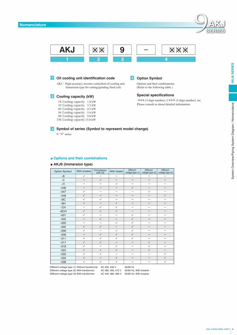
■ Options and their combinations
■ AKJ9 (Immersion type)
1 Oil cooling unit identification code
2
Symbol of series (Symbol to represent model change)9: “9” series
3
Cooling capacity (kW) 18:Cooling capacity 1.8 kW 35:Cooling capacity 3.5 kW 45:Cooling capacity 4.5 kW 56:Cooling capacity 5.6 kW 90:Cooling capacity 9.0 kW 150:Cooling capacity 15.0 kW
4 Option Symbol
Special specifications
AKJ1 2
3
94
−
- (3-digit number), C (3-digit number), etc.Please consult us about detailed information.
43
AKJ : High-accuracy inverter controlled oil cooling unit Immersion type for cutting/grinding fluid (oil)
Options and their combinations (Refer to the following table.)
Option Symbol With breaker Compliance with CE With heater Different
voltage type (1)Different
voltage type (2)Different
voltage type (3)
−B - - - - -−C - - - - -−H - - - - -
−046 - - - - -−047 - - - -−048 - - - -
−BC - - - -−BH - - - -−CH - - - -
−BCH - - -−001 - - - -−002 - - - -−003 - - - -−005 - - -−006 - - -−008 - - -−011 - -−017 - - -−018 - - -−023 - -−032 - - -−033 - - -−038 - -
Different voltage type (1) Without transformer
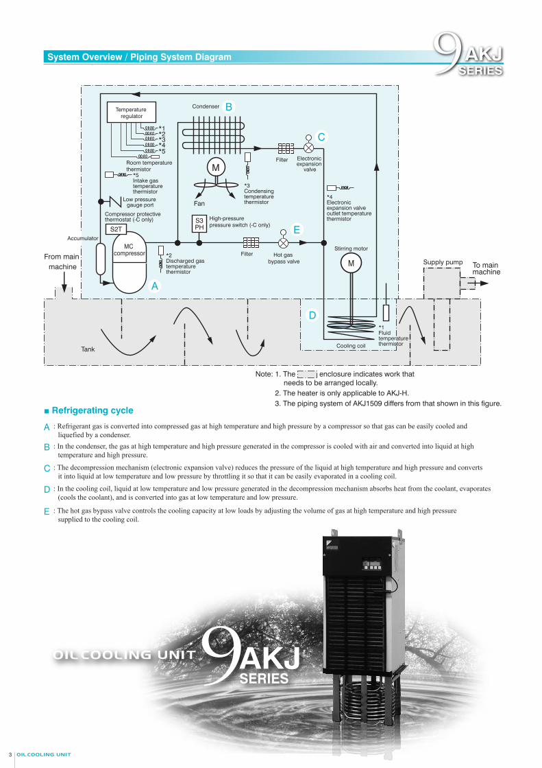
: Refrigerant gas is converted into compressed gas at high temperature and high pressure by a compressor so that gas can be easily cooled and liquefied by a condenser.
A
■ Refrigerating cycle
Fan
*3 Condensing temperature thermistor
Room temperature thermistor
High-pressure pressure switch (-C only)
From main machine
*1 *2*3*4*5
Temperature regulator
M
M
*4 Electronic expansion valve outlet temperature thermistor
*5 Intake gas temperature thermistor
Supply pump To main machine
Stirring motor
S3PH
Tank Cooling coil
*1 Fluid temperature thermistor
Note: 1. The enclosure indicates work that needs to be arranged locally.
Filter
Filter
Condenser
Electronic expansion
valve
*2 Discharged gas temperature thermistor
MC compressor
Compressor protective thermostat (-C only)
Low pressure gauge port
Accumulator
S2T
Hot gas bypass valve
C
B
D
E
A
9AKJ SERIES
: In the condenser, the gas at high temperature and high pressure generated in the compressor is cooled with air and converted into liquid at high temperature and high pressure.
: The decompression mechanism (electronic expansion valve) reduces the pressure of the liquid at high temperature and high pressure and converts it into liquid at low temperature and low pressure by throttling it so that it can be easily evaporated in a cooling coil.
: In the cooling coil, liquid at low temperature and low pressure generated in the decompression mechanism absorbs heat from the coolant, evaporates (cools the coolant), and is converted into gas at low temperature and low pressure.
: The hot gas bypass valve controls the cooling capacity at low loads by adjusting the volume of gas at high temperature and high pressure supplied to the cooling coil.
B
C
D
E
2. The heater is only applicable to AKJ-H.3. The piping system of AKJ1509 differs from that shown in this figure.
AC 220, 230 V AC 380, 400, 415 V
50/60 HzDifferent voltage type (2) With transformer 50/60 Hz, With breakerDifferent voltage type (3) With transformer AC 440, 460, 480 V 50/60 Hz, With breaker
System Overview / Piping System Diagram Nomenclature9AKJSERIES 9AKJ
SERIES
Sys
tem
Ove
rvie
w/P
ipin
g S
yste
m D
iagr
am /
Nom
encl
atur
eA
KJ9
SE
RIE
S
■ Options and their combinations
■ AKJ9 (Immersion type)
1 Oil cooling unit identification code
2
Symbol of series (Symbol to represent model change)9: “9” series
3
Cooling capacity (kW) 18:Cooling capacity 1.8 kW 35:Cooling capacity 3.5 kW 45:Cooling capacity 4.5 kW 56:Cooling capacity 5.6 kW 90:Cooling capacity 9.0 kW 150:Cooling capacity 15.0 kW
4 Option Symbol
Special specifications
AKJ1 2
3
94
−
- (3-digit number), C (3-digit number), etc.Please consult us about detailed information.
43
AKJ : High-accuracy inverter controlled oil cooling unit Immersion type for cutting/grinding fluid (oil)
Options and their combinations (Refer to the following table.)
Option Symbol With breaker Compliance with CE With heater Different
voltage type (1)Different
voltage type (2)Different
voltage type (3)
−B - - - - -−C - - - - -−H - - - - -
−046 - - - - -−047 - - - -−048 - - - -
−BC - - - -−BH - - - -−CH - - - -
−BCH - - -−001 - - - -−002 - - - -−003 - - - -−005 - - -−006 - - -−008 - - -−011 - -−017 - - -−018 - - -−023 - -−032 - - -−033 - - -−038 - -
Different voltage type (1) Without transformer
: Refrigerant gas is converted into compressed gas at high temperature and high pressure by a compressor so that gas can be easily cooled and liquefied by a condenser.
A
■ Refrigerating cycle
Fan
*3 Condensing temperature thermistor
Room temperature thermistor
High-pressure pressure switch (-C only)
From main machine
*1 *2*3*4*5
Temperature regulator
M
M
*4 Electronic expansion valve outlet temperature thermistor
*5 Intake gas temperature thermistor
Supply pump To main machine
Stirring motor
S3PH
Tank Cooling coil
*1 Fluid temperature thermistor
Note: 1. The enclosure indicates work that needs to be arranged locally.
Filter
Filter
Condenser
Electronic expansion
valve
*2 Discharged gas temperature thermistor
MC compressor
Compressor protective thermostat (-C only)
Low pressure gauge port
Accumulator
S2T
Hot gas bypass valve
C
B
D
E
A
9AKJ SERIES
: In the condenser, the gas at high temperature and high pressure generated in the compressor is cooled with air and converted into liquid at high temperature and high pressure.
: The decompression mechanism (electronic expansion valve) reduces the pressure of the liquid at high temperature and high pressure and converts it into liquid at low temperature and low pressure by throttling it so that it can be easily evaporated in a cooling coil.
: In the cooling coil, liquid at low temperature and low pressure generated in the decompression mechanism absorbs heat from the coolant, evaporates (cools the coolant), and is converted into gas at low temperature and low pressure.
: The hot gas bypass valve controls the cooling capacity at low loads by adjusting the volume of gas at high temperature and high pressure supplied to the cooling coil.
B
C
D
E
2. The heater is only applicable to AKJ-H.3. The piping system of AKJ1509 differs from that shown in this figure.
AC 220, 230 V AC 380, 400, 415 V
50/60 HzDifferent voltage type (2) With transformer 50/60 Hz, With breakerDifferent voltage type (3) With transformer AC 440, 460, 480 V 50/60 Hz, With breaker
System Overview / Piping System Diagram Nomenclature9AKJSERIES 9AKJ
SERIES
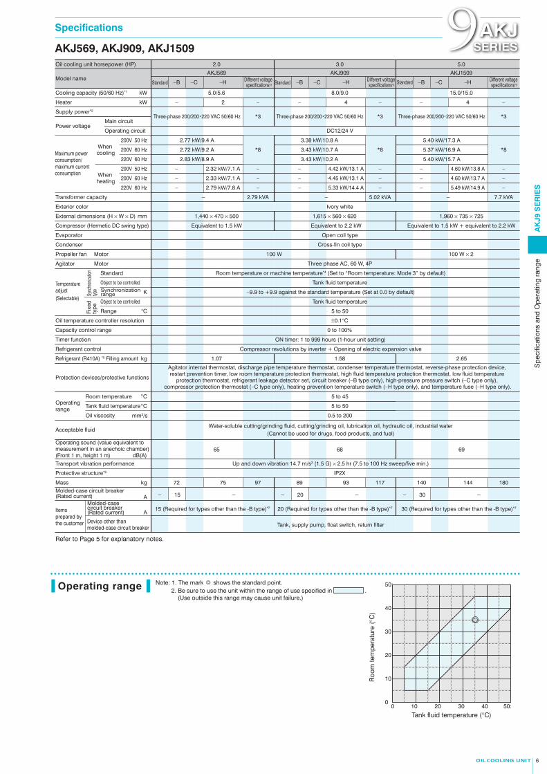
Note: 1. The mark ◎ shows the standard point.2. Be sure to use the unit within the range of use specified in .
(Use outside this range may cause unit failure.)
AKJ189, AKJ359, AKJ459 AKJ569, AKJ909, AKJ1509
40
30
20
10
00 10 20 30 40 50:
50:
Roo
m te
mpe
ratu
re (
°C)
Tank fluid temperature (°C)
■ AKJ569 ■ AKJ909■ AKJ189Supply power
380V400V415V440V460V480V
50/60Hz
Power/current
1.8A1.7A1.6A1.5A1.5A1.4A
0.83kW
■ AKJ359Supply power
380V400V415V440V460V480V
50/60Hz
Power/current
2.8A2.6A2.5A2.4A2.3A2.2A
1.38kW
■ AKJ459 ■ AKJ1509Supply power
380V400V415V440V460V480V
50/60Hz
Power/current
3.0A2.8A2.7A2.6A2.5A2.4A
1.48kW
220V
230V
220V
230V
220V
230V
50Hz60Hz50Hz60Hz
3.0A3.0A2.9A2.8A
0.82kW0.83kW0.82kW0.83kW
50Hz60Hz50Hz60Hz
4.8A4.8A4.6A4.6A
1.38kW1.38kW1.39kW1.38kW
50Hz60Hz50Hz60Hz
5.1A5.1A4.9A4.7A
1.46kW1.48kW1.46kW1.48kW
Supply power
380V400V415V440V460V480V
50/60Hz
Power/current
4.9A4.7A4.5A4.3A4.1A3.9A
2.77kW
Supply power
380V400V415V440V460V480V
50/60Hz
Power/current
5.7A5.4A5.2A4.9A4.7A4.5A
3.43kW
Supply power
380V400V415V440V460V480V
50/60Hz
Power/current
9.1A8.7A8.4A7.9A7.5A7.3A
5.40kW
220V
230V
220V
230V
220V
230V
50Hz60Hz50Hz60Hz
9.0A8.9A8.6A8.3A
2.92kW2.83kW2.92kW2.83kW
50Hz60Hz50Hz60Hz
10.3A10.2A9.9A9.8A
3.41kW3.43kW3.41kW3.44kW
50Hz60Hz50Hz60Hz
15.8A15.7A15.4A15.3A
5.38kW5.40kW5.38kW5.41kW
Operating range
5 6
Oil cooling unit horsepower (HP) 2.0
DC12/24 V
Open coil type
Cross-fin coil type
Three phase AC, 60 W, 4P
Room temperature or machine temperature*4 (Set to “Room temperature: Mode 3” by default)
Tank fluid temperature
−9.9 to +9.9 against the standard temperature (Set at 0.0 by default)
Tank fluid temperature
5 to 50
5 to 45
5 to 50
0.5 to 200
Up and down vibration 14.7 m/s2 (1.5 G) × 2.5 hr (7.5 to 100 Hz sweep/five min.)
Tank, supply pump, float switch, return filter
Water-soluble cutting/grinding fluid, cutting/grinding oil, lubrication oil, hydraulic oil, industrial water(Cannot be used for drugs, food products, and fuel)
Compressor revolutions by inverter + Opening of electric expansion valve
Ivory white
3.0
5.0/5.6 8.0/9.0
Equivalent to 1.5 kW Equivalent to 2.2 kW
1.07 1.58
65 68
15 (Required for types other than the -B type)*7
AKJ569 AKJ909
−H−C−BStandard
Cooling capacity (50/60 Hz)*1 kW
kW
200V 50 Hz
200V 60 Hz
220V 60 Hz
mm
K
°C
°C
°C
kg
Heater
Supply power*2
Transformer capacity
Exterior color
External dimensions (H × W × D)
Compressor (Hermetic DC swing type)
Evaporator
Condenser
Propeller fan Motor
Agitator Motor
Refrigerant control
Transport vibration performance
Device other than molded-case circuit breaker
Molded-case circuit breaker (Rated current)
Refrigerant (R410A) *5 Filling amount
Acceptable fluid
Protection devices/protective functions
Temperature adjust
Sync
hroniz
ation
typ
eFi
xed
type
Standard
Object to be controlledSynchronization range
Object to be controlled
Range
Main circuit
Operating circuitPower voltage
Model name
(Selectable)
Operating range
Oil viscosity
Tank fluid temperature
Room temperature
kgMass
AMolded-case circuit breaker (Rated current)
A
−H−C−BStandard
2– – 4– –
2.77 kW/9.4 A 3.38 kW/10.8 A
2.72 kW/9.2 A 3.43 kW/10.7 A
2.83 kW/8.9 A 3.43 kW/10.2 A
200V 50 Hz
200V 60 Hz
220V 60 Hz
2.32 kW/7.1 A– – 4.42 kW/13.1 A– –
2.33 kW/7.1 A– – 4.45 kW/13.1 A– –
–2.79 kW/7.8 A– – 5.33 kW/14.4 A–
1177572 97 9389
20 (Required for types other than the -B type)*7
−− 15 −− 20
− 2.79 kVA − 5.02 kVA
Three-phase 200/200・220 VAC 50/60 Hz *3 Three-phase 200/200・220 VAC 50/60 Hz *3
*8 *8
1,440 × 470 × 500 1,615 × 560 × 620
When cooling
When heating
100 W
Refer to Page 5 for explanatory notes.
5.0
15.0/15.0
Equivalent to 1.5 kW + equivalent to 2.2 kW
AKJ1509
−H−C−BStandard
4– –
5.40 kW/17.3 A
5.37 kW/16.9 A
5.40 kW/15.7 A
4.60 kW/13.8 A– –
4.60 kW/13.7 A– –
5.49 kW/14.9 A– –
− 7.7 kVA
Three-phase 200/200・220 VAC 50/60 Hz *3
*8
1,960 × 735 × 725
100 W × 2
2.65
69
30 (Required for types other than the -B type)*7
144140 180
−− 30
Different voltage specifications*3
Different voltage specifications*3
Different voltage specifications*3
Maximum power consumption/maximum current consumption
Specifications Specifications9AKJSERIES 9AKJ
SERIES
AK
J9 S
ER
IES
Spe
cific
atio
ns a
nd O
pera
ting
rang
e
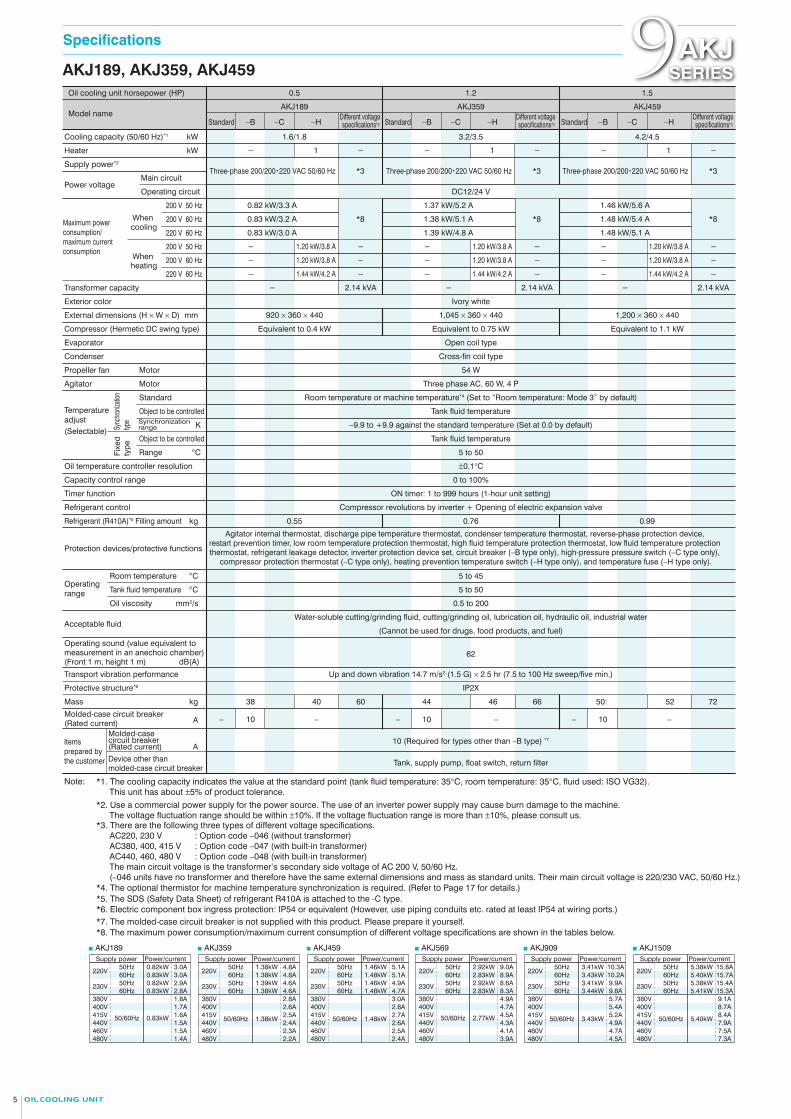
Oil cooling unit horsepower (HP) 0.5 1.2 1.5
AKJ189
−C−BStandard −H
AKJ359 AKJ459
1.6/1.8 3.2/3.5
DC12/24 V
Ivory white
Open coil type
Cross-fin coil type
54 W
Three phase AC, 60 W, 4 P
Room temperature or machine temperature*4 (Set to “Room temperature: Mode 3” by default)
Tank fluid temperature
−9.9 to +9.9 against the standard temperature (Set at 0.0 by default)
Tank fluid temperature
5 to 50
±0.1°C
0 to 100%
ON timer: 1 to 999 hours (1-hour unit setting)
5 to 45
5 to 50
0.5 to 200
62
Up and down vibration 14.7 m/s2 (1.5 G) × 2.5 hr (7.5 to 100 Hz sweep/five min.)
10 (Required for types other than –B type) *7
Tank, supply pump, float switch, return filter
Water-soluble cutting/grinding fluid, cutting/grinding oil, lubrication oil, hydraulic oil, industrial water
(Cannot be used for drugs, food products, and fuel)
Compressor revolutions by inverter + Opening of electric expansion valve
Agitator internal thermostat, discharge pipe temperature thermostat, condenser temperature thermostat, reverse-phase protection device, restart prevention timer, low room temperature protection thermostat, high fluid temperature protection thermostat, low fluid temperature protection thermostat, refrigerant leakage detector, inverter protection device set, circuit breaker (−B type only), high-pressure pressure switch (−C type only),
compressor protection thermostat (−C type only), heating prevention temperature switch (−H type only), and temperature fuse (−H type only).
Agitator internal thermostat, discharge pipe temperature thermostat, condenser temperature thermostat, reverse-phase protection device, restart prevention timer, low room temperature protection thermostat, high fluid temperature protection thermostat, low fluid temperature
protection thermostat, refrigerant leakage detector set, circuit breaker (−B type only), high-pressure pressure switch (−C type only), compressor protection thermostat (−C type only), heating prevention temperature switch (−H type only), and temperature fuse (−H type only).
4.2/4.5
Equivalent to 0.4 kW Equivalent to 0.75 kW Equivalent to 1.1 kW
0.55
4038 60
–10– 10– 10–– –
4644 66 5250: 72
0.76 0.99
Cooling capacity (50/60 Hz)*1 kW
kW
200 V 50 Hz
200 V 60 Hz
220 V 60 Hz
mm
K
°C
°C
°C
kg
Heater
Supply power*2
Transformer capacity
Exterior color
External dimensions (H × W × D)
Compressor (Hermetic DC swing type)
Evaporator
Condenser
Propeller fan Motor
Agitator Motor
Refrigerant control
Transport vibration performance
IP2XProtective structure*6
Items prepared by the customer
Items prepared by the customerDevice other than
molded-case circuit breaker
Refrigerant (R410A)*5 Filling amount
Acceptable fluid
Operating sound (value equivalent to measurement in an anechoic chamber) (Front 1 m, height 1 m)
Protection devices/protective functions
Temperature adjust
Sync
hroniz
ation
typ
eFi
xed
type
Standard
Object to be controlledSynchronization range
Object to be controlled
Range
Main circuit
When cooling
When heating
Operating circuitPower voltage
Model name
(Selectable)
Operating range
Oil viscosity
Tank fluid temperature
Room temperature
Different voltage specifications*3 −C−BStandard −H
Different voltage specifications*3 −C−BStandard −H
Different voltage specifications*3
kg
dB(A)
Operating sound (value equivalent to measurement in an anechoic chamber) (Front 1 m, height 1 m) dB(A)
Mass
Capacity control range
Oil temperature controller resolution
Timer function
AMolded-case circuit breaker (Rated current)
Molded-case circuit breaker (Rated current) A
*3Three-phase 200/200・220 VAC 50/60 Hz *3Three-phase 200/200・220 VAC 50/60 Hz *3
*8 *8 *8
Three-phase 200/200・220 VAC 50/60 Hz
− 1
Note:
− − 1 − − 1 −
0.82 kW/3.3 A 1.37 kW/5.2 A 1.46 kW/5.6 A
0.83 kW/3.2 A 1.38 kW/5.1 A 1.48 kW/5.4 A
0.83 kW/3.0 A 1.39 kW/4.8 A 1.48 kW/5.1 A
− 2.14 kVA − 2.14 kVA − 2.14 kVA
920 × 360 × 440 1,045 × 360 × 440 1,200 × 360 × 440
200 V 50 Hz
200 V 60 Hz
220 V 60 Hz
− 1.20 kW/3.8 A − − 1.20 kW/3.8 A − − 1.20 kW/3.8 A −
− 1.20 kW/3.8 A − − 1.20 kW/3.8 A − − 1.20 kW/3.8 A −
− 1.44 kW/4.2 A − − 1.44 kW/4.2 A − − 1.44 kW/4.2 A −
*1. The cooling capacity indicates the value at the standard point (tank fluid temperature: 35°C, room temperature: 35°C, fluid used: ISO VG32). This unit has about ±5% of product tolerance.
±0.1°C
0 to 100%
ON timer: 1 to 999 hours (1-hour unit setting)
Capacity control range
Oil temperature controller resolution
Timer function
IP2XProtective structure*6
*2. Use a commercial power supply for the power source. The use of an inverter power supply may cause burn damage to the machine. The voltage fluctuation range should be within ±10%. If the voltage fluctuation range is more than ±10%, please consult us.
*3. There are the following three types of different voltage specifications.AC220, 230 V : Option code −046 (without transformer)AC380, 400, 415 V : Option code −047 (with built-in transformer)AC440, 460, 480 V : Option code −048 (with built-in transformer)The main circuit voltage is the transformer’s secondary side voltage of AC 200 V, 50/60 Hz.(−046 units have no transformer and therefore have the same external dimensions and mass as standard units. Their main circuit voltage is 220/230 VAC, 50/60 Hz.)
*4. The optional thermistor for machine temperature synchronization is required. (Refer to Page 17 for details.)*5. The SDS (Safety Data Sheet) of refrigerant R410A is attached to the -C type.
*7. The molded-case circuit breaker is not supplied with this product. Please prepare it yourself.*6. Electric component box ingress protection: IP54 or equivalent (However, use piping conduits etc. rated at least IP54 at wiring ports.)
*8. The maximum power consumption/maximum current consumption of different voltage specifications are shown in the tables below.
Maximum power consumption/maximum current consumption
mm2/s mm2/s
Note: 1. The mark ◎ shows the standard point.2. Be sure to use the unit within the range of use specified in .
(Use outside this range may cause unit failure.)
AKJ189, AKJ359, AKJ459 AKJ569, AKJ909, AKJ1509
40
30
20
10
00 10 20 30 40 50:
50:
Roo
m te
mpe
ratu
re (
°C)
Tank fluid temperature (°C)
■ AKJ569 ■ AKJ909■ AKJ189Supply power
380V400V415V440V460V480V
50/60Hz
Power/current
1.8A1.7A1.6A1.5A1.5A1.4A
0.83kW
■ AKJ359Supply power
380V400V415V440V460V480V
50/60Hz
Power/current
2.8A2.6A2.5A2.4A2.3A2.2A
1.38kW
■ AKJ459 ■ AKJ1509Supply power
380V400V415V440V460V480V
50/60Hz
Power/current
3.0A2.8A2.7A2.6A2.5A2.4A
1.48kW
220V
230V
220V
230V
220V
230V
50Hz60Hz50Hz60Hz
3.0A3.0A2.9A2.8A
0.82kW0.83kW0.82kW0.83kW
50Hz60Hz50Hz60Hz
4.8A4.8A4.6A4.6A
1.38kW1.38kW1.39kW1.38kW
50Hz60Hz50Hz60Hz
5.1A5.1A4.9A4.7A
1.46kW1.48kW1.46kW1.48kW
Supply power
380V400V415V440V460V480V
50/60Hz
Power/current
4.9A4.7A4.5A4.3A4.1A3.9A
2.77kW
Supply power
380V400V415V440V460V480V
50/60Hz
Power/current
5.7A5.4A5.2A4.9A4.7A4.5A
3.43kW
Supply power
380V400V415V440V460V480V
50/60Hz
Power/current
9.1A8.7A8.4A7.9A7.5A7.3A
5.40kW
220V
230V
220V
230V
220V
230V
50Hz60Hz50Hz60Hz
9.0A8.9A8.6A8.3A
2.92kW2.83kW2.92kW2.83kW
50Hz60Hz50Hz60Hz
10.3A10.2A9.9A9.8A
3.41kW3.43kW3.41kW3.44kW
50Hz60Hz50Hz60Hz
15.8A15.7A15.4A15.3A
5.38kW5.40kW5.38kW5.41kW
Operating range
5 6
Oil cooling unit horsepower (HP) 2.0
DC12/24 V
Open coil type
Cross-fin coil type
Three phase AC, 60 W, 4P
Room temperature or machine temperature*4 (Set to “Room temperature: Mode 3” by default)
Tank fluid temperature
−9.9 to +9.9 against the standard temperature (Set at 0.0 by default)
Tank fluid temperature
5 to 50
5 to 45
5 to 50
0.5 to 200
Up and down vibration 14.7 m/s2 (1.5 G) × 2.5 hr (7.5 to 100 Hz sweep/five min.)
Tank, supply pump, float switch, return filter
Water-soluble cutting/grinding fluid, cutting/grinding oil, lubrication oil, hydraulic oil, industrial water(Cannot be used for drugs, food products, and fuel)
Compressor revolutions by inverter + Opening of electric expansion valve
Ivory white
3.0
5.0/5.6 8.0/9.0
Equivalent to 1.5 kW Equivalent to 2.2 kW
1.07 1.58
65 68
15 (Required for types other than the -B type)*7
AKJ569 AKJ909
−H−C−BStandard
Cooling capacity (50/60 Hz)*1 kW
kW
200V 50 Hz
200V 60 Hz
220V 60 Hz
mm
K
°C
°C
°C
kg
Heater
Supply power*2
Transformer capacity
Exterior color
External dimensions (H × W × D)
Compressor (Hermetic DC swing type)
Evaporator
Condenser
Propeller fan Motor
Agitator Motor
Refrigerant control
Transport vibration performance
Device other than molded-case circuit breaker
Molded-case circuit breaker (Rated current)
Refrigerant (R410A) *5 Filling amount
Acceptable fluid
Protection devices/protective functions
Temperature adjust
Sync
hroniz
ation
typ
eFi
xed
type
Standard
Object to be controlledSynchronization range
Object to be controlled
Range
Main circuit
Operating circuitPower voltage
Model name
(Selectable)
Operating range
Oil viscosity
Tank fluid temperature
Room temperature
kgMass
AMolded-case circuit breaker (Rated current)
A
−H−C−BStandard
2– – 4– –
2.77 kW/9.4 A 3.38 kW/10.8 A
2.72 kW/9.2 A 3.43 kW/10.7 A
2.83 kW/8.9 A 3.43 kW/10.2 A
200V 50 Hz
200V 60 Hz
220V 60 Hz
2.32 kW/7.1 A– – 4.42 kW/13.1 A– –
2.33 kW/7.1 A– – 4.45 kW/13.1 A– –
–2.79 kW/7.8 A– – 5.33 kW/14.4 A–
1177572 97 9389
20 (Required for types other than the -B type)*7
−− 15 −− 20
− 2.79 kVA − 5.02 kVA
Three-phase 200/200・220 VAC 50/60 Hz *3 Three-phase 200/200・220 VAC 50/60 Hz *3
*8 *8
1,440 × 470 × 500 1,615 × 560 × 620
When cooling
When heating
100 W
Refer to Page 5 for explanatory notes.
5.0
15.0/15.0
Equivalent to 1.5 kW + equivalent to 2.2 kW
AKJ1509
−H−C−BStandard
4– –
5.40 kW/17.3 A
5.37 kW/16.9 A
5.40 kW/15.7 A
4.60 kW/13.8 A– –
4.60 kW/13.7 A– –
5.49 kW/14.9 A– –
− 7.7 kVA
Three-phase 200/200・220 VAC 50/60 Hz *3
*8
1,960 × 735 × 725
100 W × 2
2.65
69
30 (Required for types other than the -B type)*7
144140 180
−− 30
Different voltage specifications*3
Different voltage specifications*3
Different voltage specifications*3
Maximum power consumption/maximum current consumption
Specifications Specifications9AKJSERIES 9AKJ
SERIES
AK
J9 S
ER
IES
Spe
cific
atio
ns a
nd O
pera
ting
rang
e
Oil cooling unit horsepower (HP) 0.5 1.2 1.5
AKJ189
−C−BStandard −H
AKJ359 AKJ459
1.6/1.8 3.2/3.5
DC12/24 V
Ivory white
Open coil type
Cross-fin coil type
54 W
Three phase AC, 60 W, 4 P
Room temperature or machine temperature*4 (Set to “Room temperature: Mode 3” by default)
Tank fluid temperature
−9.9 to +9.9 against the standard temperature (Set at 0.0 by default)
Tank fluid temperature
5 to 50
±0.1°C
0 to 100%
ON timer: 1 to 999 hours (1-hour unit setting)
5 to 45
5 to 50
0.5 to 200
62
Up and down vibration 14.7 m/s2 (1.5 G) × 2.5 hr (7.5 to 100 Hz sweep/five min.)
10 (Required for types other than –B type) *7
Tank, supply pump, float switch, return filter
Water-soluble cutting/grinding fluid, cutting/grinding oil, lubrication oil, hydraulic oil, industrial water
(Cannot be used for drugs, food products, and fuel)
Compressor revolutions by inverter + Opening of electric expansion valve
Agitator internal thermostat, discharge pipe temperature thermostat, condenser temperature thermostat, reverse-phase protection device, restart prevention timer, low room temperature protection thermostat, high fluid temperature protection thermostat, low fluid temperature protection thermostat, refrigerant leakage detector, inverter protection device set, circuit breaker (−B type only), high-pressure pressure switch (−C type only),
compressor protection thermostat (−C type only), heating prevention temperature switch (−H type only), and temperature fuse (−H type only).
Agitator internal thermostat, discharge pipe temperature thermostat, condenser temperature thermostat, reverse-phase protection device, restart prevention timer, low room temperature protection thermostat, high fluid temperature protection thermostat, low fluid temperature
protection thermostat, refrigerant leakage detector set, circuit breaker (−B type only), high-pressure pressure switch (−C type only), compressor protection thermostat (−C type only), heating prevention temperature switch (−H type only), and temperature fuse (−H type only).
4.2/4.5
Equivalent to 0.4 kW Equivalent to 0.75 kW Equivalent to 1.1 kW
0.55
4038 60
–10– 10– 10–– –
4644 66 5250: 72
0.76 0.99
Cooling capacity (50/60 Hz)*1 kW
kW
200 V 50 Hz
200 V 60 Hz
220 V 60 Hz
mm
K
°C
°C
°C
kg
Heater
Supply power*2
Transformer capacity
Exterior color
External dimensions (H × W × D)
Compressor (Hermetic DC swing type)
Evaporator
Condenser
Propeller fan Motor
Agitator Motor
Refrigerant control
Transport vibration performance
IP2XProtective structure*6
Items prepared by the customer
Items prepared by the customerDevice other than
molded-case circuit breaker
Refrigerant (R410A)*5 Filling amount
Acceptable fluid
Operating sound (value equivalent to measurement in an anechoic chamber) (Front 1 m, height 1 m)
Protection devices/protective functions
Temperature adjust
Sync
hroniz
ation
typ
eFi
xed
type
Standard
Object to be controlledSynchronization range
Object to be controlled
Range
Main circuit
When cooling
When heating
Operating circuitPower voltage
Model name
(Selectable)
Operating range
Oil viscosity
Tank fluid temperature
Room temperature
Different voltage specifications*3 −C−BStandard −H
Different voltage specifications*3 −C−BStandard −H
Different voltage specifications*3
kg
dB(A)
Operating sound (value equivalent to measurement in an anechoic chamber) (Front 1 m, height 1 m) dB(A)
Mass
Capacity control range
Oil temperature controller resolution
Timer function
AMolded-case circuit breaker (Rated current)
Molded-case circuit breaker (Rated current) A
*3Three-phase 200/200・220 VAC 50/60 Hz *3Three-phase 200/200・220 VAC 50/60 Hz *3
*8 *8 *8
Three-phase 200/200・220 VAC 50/60 Hz
− 1
Note:
− − 1 − − 1 −
0.82 kW/3.3 A 1.37 kW/5.2 A 1.46 kW/5.6 A
0.83 kW/3.2 A 1.38 kW/5.1 A 1.48 kW/5.4 A
0.83 kW/3.0 A 1.39 kW/4.8 A 1.48 kW/5.1 A
− 2.14 kVA − 2.14 kVA − 2.14 kVA
920 × 360 × 440 1,045 × 360 × 440 1,200 × 360 × 440
200 V 50 Hz
200 V 60 Hz
220 V 60 Hz
− 1.20 kW/3.8 A − − 1.20 kW/3.8 A − − 1.20 kW/3.8 A −
− 1.20 kW/3.8 A − − 1.20 kW/3.8 A − − 1.20 kW/3.8 A −
− 1.44 kW/4.2 A − − 1.44 kW/4.2 A − − 1.44 kW/4.2 A −
*1. The cooling capacity indicates the value at the standard point (tank fluid temperature: 35°C, room temperature: 35°C, fluid used: ISO VG32). This unit has about ±5% of product tolerance.
±0.1°C
0 to 100%
ON timer: 1 to 999 hours (1-hour unit setting)
Capacity control range
Oil temperature controller resolution
Timer function
IP2XProtective structure*6
*2. Use a commercial power supply for the power source. The use of an inverter power supply may cause burn damage to the machine. The voltage fluctuation range should be within ±10%. If the voltage fluctuation range is more than ±10%, please consult us.
*3. There are the following three types of different voltage specifications.AC220, 230 V : Option code −046 (without transformer)AC380, 400, 415 V : Option code −047 (with built-in transformer)AC440, 460, 480 V : Option code −048 (with built-in transformer)The main circuit voltage is the transformer’s secondary side voltage of AC 200 V, 50/60 Hz.(−046 units have no transformer and therefore have the same external dimensions and mass as standard units. Their main circuit voltage is 220/230 VAC, 50/60 Hz.)
*4. The optional thermistor for machine temperature synchronization is required. (Refer to Page 17 for details.)*5. The SDS (Safety Data Sheet) of refrigerant R410A is attached to the -C type.
*7. The molded-case circuit breaker is not supplied with this product. Please prepare it yourself.*6. Electric component box ingress protection: IP54 or equivalent (However, use piping conduits etc. rated at least IP54 at wiring ports.)
*8. The maximum power consumption/maximum current consumption of different voltage specifications are shown in the tables below.
Maximum power consumption/maximum current consumption
mm2/s mm2/s
AKJ569
AKJ909
AKJ189
AKJ359
AKJ459 AKJ1509
7 8
Cooling Capacity Characteristic Chart Cooling Capacity Characteristic Chart9AKJSERIES 9AKJ
SERIES
AK
J9 S
ER
IES
Coo
ling
Cap
acity
Cha
ract
eris
tic C
hart
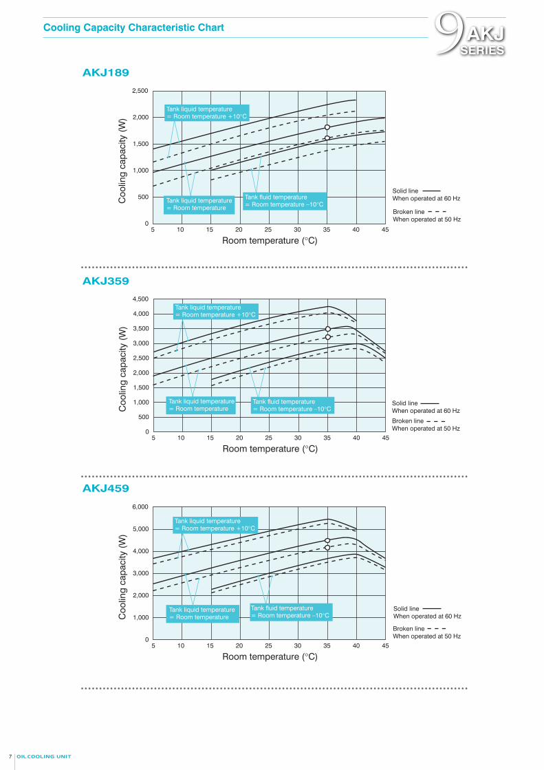
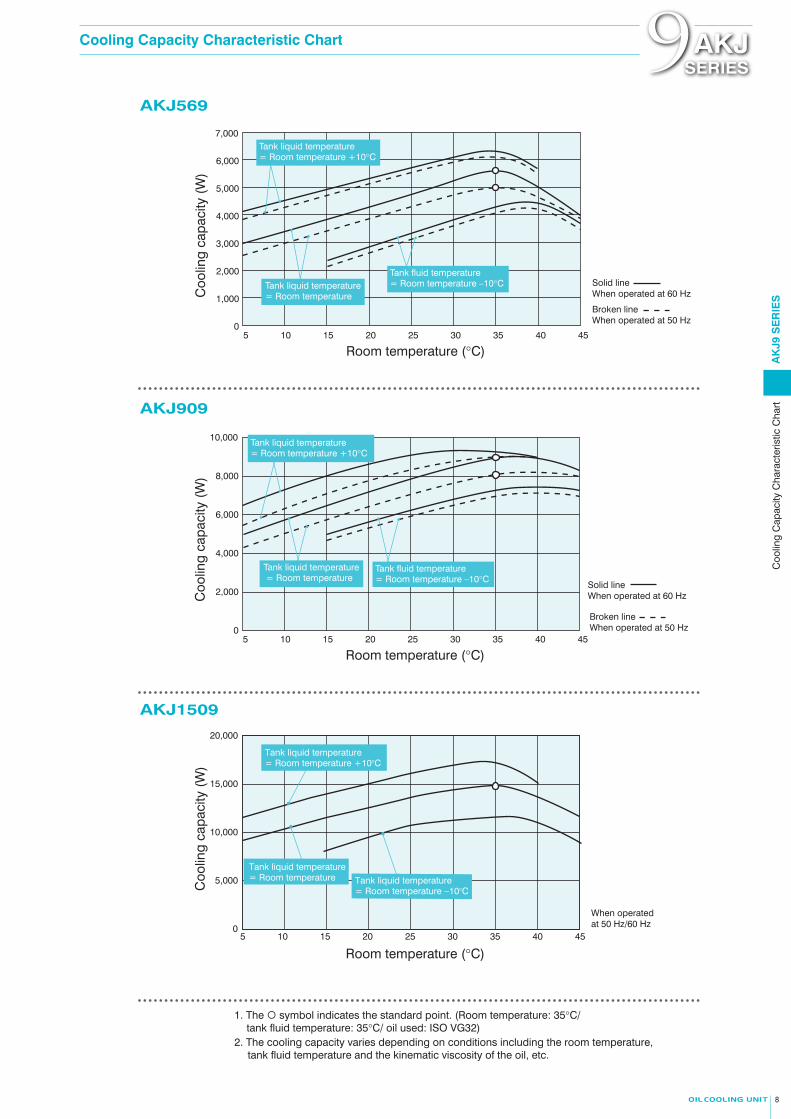
1. The symbol indicates the standard point. (Room temperature: 35°C/ tank fluid temperature: 35°C/ oil used: ISO VG32)
Solid line When operated at 60 Hz
Solid line When operated at 60 Hz
Solid line When operated at 60 Hz
Solid line When operated at 60 Hz
Solid line When operated at 60 Hz
Coo
ling
capa
city
(W
)
255 10 15 20 30 35 40 45
Room temperature (°C)
500
0
2,500
2,000
1,000
1,500
Coo
ling
capa
city
(W
)
255 10 15 20 30 35 40 45
Room temperature (°C)
500
0
4,500
4,000
3,500
3,000
2,500
1,500
1,000
2,000
Coo
ling
capa
city
(W
)
255 10 15 20 30 35 40 45
Room temperature (°C)
0
6,000
4,000
5,000
3,000
2,000
1,000
Tank liquid temperature = Room temperature +10°C
Tank liquid temperature = Room temperature
Tank fluid temperature = Room temperature −10°C
Tank liquid temperature = Room temperature +10°C
Tank liquid temperature = Room temperature
Tank fluid temperature = Room temperature –10°C
Tank liquid temperature = Room temperature +10°C
Tank liquid temperature = Room temperature
Tank fluid temperature = Room temperature –10°C
Coo
ling
capa
city
(W
)
255 10 15 20 30 35 40 45
Room temperature (°C)
0
7,000
5,000
6,000
4,000
3,000
2,000
1,000
Coo
ling
capa
city
(W
)
255 10 15 20 30 35 40 45
255 10 15 20 30 35 40 45
Room temperature (°C)
Room temperature (°C)
0
10,000
6,000
8,000
4,000
2,000
Tank liquid temperature = Room temperature +10°C
Tank liquid temperature = Room temperature
Tank fluid temperature = Room temperature –10°C
Tank liquid temperature = Room temperature +10°C
Tank liquid temperature = Room temperature
Tank fluid temperature = Room temperature –10°C
When operated at 50 Hz/60 Hz0
15,000
20,000
10,000
5,000Coo
ling
capa
city
(W
)
Tank liquid temperature = Room temperature
Tank liquid temperature = Room temperature +10°C
Tank liquid temperature = Room temperature −10°C
Broken line When operated at 50 Hz
Broken line When operated at 50 Hz
Broken line When operated at 50 Hz
Broken line When operated at 50 Hz
Broken line When operated at 50 Hz
2. The cooling capacity varies depending on conditions including the room temperature, tank fluid temperature and the kinematic viscosity of the oil, etc.
AKJ569
AKJ909
AKJ189
AKJ359
AKJ459 AKJ1509
7 8
Cooling Capacity Characteristic Chart Cooling Capacity Characteristic Chart9AKJSERIES 9AKJ
SERIES
AK
J9 S
ER
IES
Coo
ling
Cap
acity
Cha
ract
eris
tic C
hart
1. The symbol indicates the standard point. (Room temperature: 35°C/ tank fluid temperature: 35°C/ oil used: ISO VG32)
Solid line When operated at 60 Hz
Solid line When operated at 60 Hz
Solid line When operated at 60 Hz
Solid line When operated at 60 Hz
Solid line When operated at 60 Hz
Coo
ling
capa
city
(W
)
255 10 15 20 30 35 40 45
Room temperature (°C)
500
0
2,500
2,000
1,000
1,500
Coo
ling
capa
city
(W
)
255 10 15 20 30 35 40 45
Room temperature (°C)
500
0
4,500
4,000
3,500
3,000
2,500
1,500
1,000
2,000
Coo
ling
capa
city
(W
)
255 10 15 20 30 35 40 45
Room temperature (°C)
0
6,000
4,000
5,000
3,000
2,000
1,000
Tank liquid temperature = Room temperature +10°C
Tank liquid temperature = Room temperature
Tank fluid temperature = Room temperature −10°C
Tank liquid temperature = Room temperature +10°C
Tank liquid temperature = Room temperature
Tank fluid temperature = Room temperature –10°C
Tank liquid temperature = Room temperature +10°C
Tank liquid temperature = Room temperature
Tank fluid temperature = Room temperature –10°C
Coo
ling
capa
city
(W
)
255 10 15 20 30 35 40 45
Room temperature (°C)
0
7,000
5,000
6,000
4,000
3,000
2,000
1,000
Coo
ling
capa
city
(W
)
255 10 15 20 30 35 40 45
255 10 15 20 30 35 40 45
Room temperature (°C)
Room temperature (°C)
0
10,000
6,000
8,000
4,000
2,000
Tank liquid temperature = Room temperature +10°C
Tank liquid temperature = Room temperature
Tank fluid temperature = Room temperature –10°C
Tank liquid temperature = Room temperature +10°C
Tank liquid temperature = Room temperature
Tank fluid temperature = Room temperature –10°C
When operated at 50 Hz/60 Hz0
15,000
20,000
10,000
5,000Coo
ling
capa
city
(W
)
Tank liquid temperature = Room temperature
Tank liquid temperature = Room temperature +10°C
Tank liquid temperature = Room temperature −10°C
Broken line When operated at 50 Hz
Broken line When operated at 50 Hz
Broken line When operated at 50 Hz
Broken line When operated at 50 Hz
Broken line When operated at 50 Hz
2. The cooling capacity varies depending on conditions including the room temperature, tank fluid temperature and the kinematic viscosity of the oil, etc.
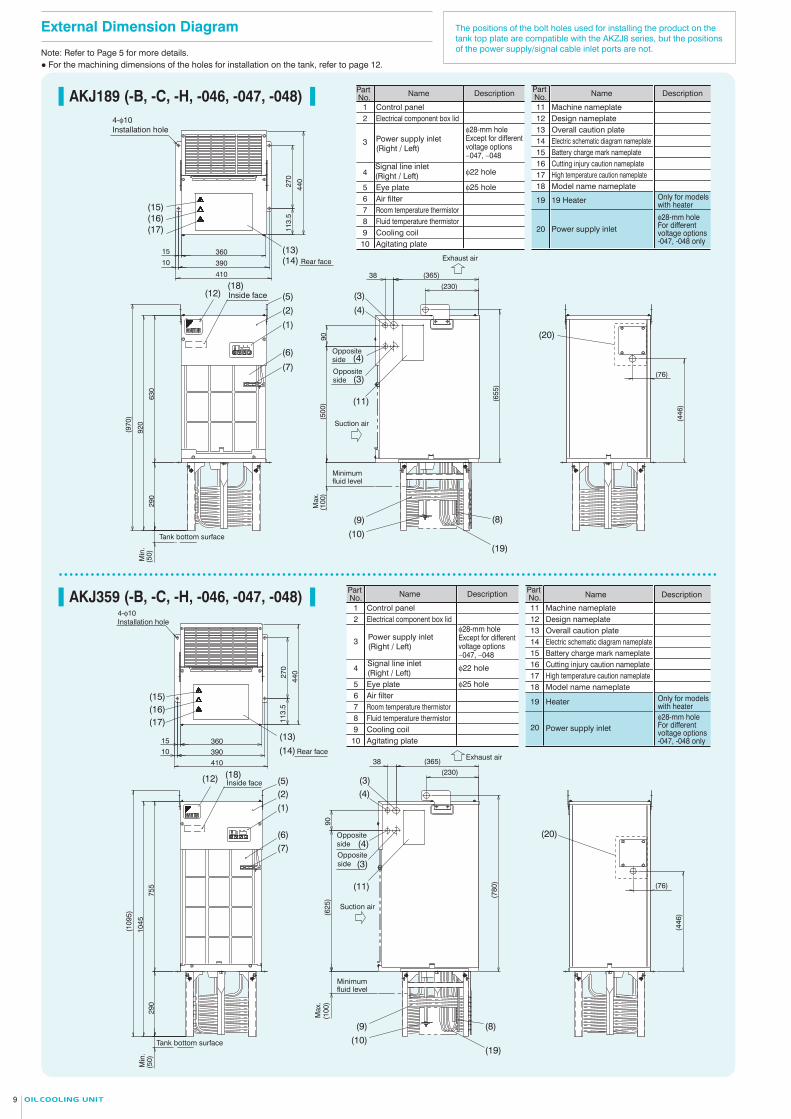
The positions of the bolt holes used for installing the product on the tank top plate are compatible with the AKZJ8 series, but the positions of the power supply/signal cable inlet ports are not.
AKJ189 (-B, -C, -H, -046, -047, -048)
AKJ359 (-B, -C, -H, -046, -047, -048)
AKJ459 (-B, -C, -H, -046, -047, -048)
AKJ569 (-B, -C, -H, -046, -047, -048)
AK
J9 S
ER
IES
Ext
erna
l Dim
ensi
on D
iagr
am
External Dimension Diagram External Dimension Diagram
Note: Refer to Page 5 for more details.● For the machining dimensions of the holes for installation on the tank, refer to page 12. 9AKJ
SERIES
Tank bottom surface
(970
)
920
630
290
Min
.(5
0)
90(5
00)
Minimum fluid level
Max
.(1
00)
Suction air
Exhaust air
38 (365)
(230)
(76)
(655
)
(446
)
Rear face
410
39010
15 360
440
270
113.
5Inside face
Opposite side
Opposite side
4-φ10 Installation hole
(13)(14)
(15)(16)(17)
(12)(18)
(5)
(2)
(1)
(6)
(7)
(3)
(3)
(4)
(4)
(11)
(9)
(10)
(8)
(19)
Rear face
44027
011
3.5
41039010
15 360
Tank bottom surface
Min
.
(109
5)
1045
755
290
(50)
90(6
25)
Minimum fluid level
Max
.(1
00)
Exhaust air38 (365)
(230)
(780
)
(446
)
(76)
Opposite side
Opposite side
Suction air
Inside face
4-φ10 Installation hole
(15)(16)(17)
(13)
(14)
(12) (18)(5)(2)(1)
(6)(7)
(3)
(3)
(4)
(4)
(11)
(9)(10)
(8)
(19)
(50)
345
855
1200
(125
0)
3601510 390
410
113.
527
044
0
(100
)(7
25)
90
(230)(365)38
(880
)
Min
.
Max
.
Tank bottom surface
Minimum fluid level
Suction air
Opposite side
Exhaust air
Opposite side
Inside face
Rear face
4-φ10 Installation hole
(15)(16)(17)
(13)(14)
(12) (18)(5)(2)(1)
(6)(7)
(3)
(3)
(4)
(4)
(11)
(9)(10)
(8)
(19)
47015
60
10 500520
380
500
Min
.
Tank bottom surface
(50)
(149
0)
1440
350
1090
Max
.
Minimum fluid level
(960
)(1
00)
90
(111
5)
(191)
(195)
(671
)
(425)38
4-φ10 Installation hole
Suction air
Exhaust air
Rear face
Inside face
Opposite sideOpposite side
(15)(16)(17)
(13)(14)
(5)
(2)(1)
(7)
(6)
(12) (18) (3)
(3)
(4)
(4)
(11)
(10)(19)
(9)
(8)
(76)
(446
)
18 Model name nameplate
19 Heater
Part No. Name Description
11 Machine nameplate12 Design nameplate13 Overall caution plate14 Electric schematic diagram nameplate15 Battery charge mark nameplate16 Cutting injury caution nameplate
Part No. Name Description
1 Control panel2 Electrical component box lid
3Power supply inlet (Right / Left)
4 Signal line inlet (Right / Left)
5 Eye plate6 Air filter7 Room temperature thermistor8 Fluid temperature thermistor9 Cooling coil
Only for models with heater
20 Power supply inletφ28-mm hole For different voltage options -047, -048 only10 Agitating plate
φ22 hole
φ28-mm hole Except for different voltage options −047, −048
φ25 hole17 High temperature caution nameplate
18 Model name nameplate
19 19 Heater
Part No. Name Description
11 Machine nameplate12 Design nameplate13 Overall caution plate14 Electric schematic diagram nameplate15 Battery charge mark nameplate16 Cutting injury caution nameplate
Part No. Name Description
1 Control panel2 Electrical component box lid
3 Power supply inlet (Right / Left)
4Signal line inlet (Right / Left)
5 Eye plate6 Air filter7 Room temperature thermistor8 Fluid temperature thermistor9 Cooling coil
Only for models with heater
20 Power supply inletφ28-mm hole For different voltage options -047, -048 only10 Agitating plate
φ22 hole
φ28-mm hole Except for different voltage options −047, −048
φ25 hole
17 High temperature caution nameplate
18 Model name nameplate
19 Heater
Part No. Name Description
11 Machine nameplate12 Design nameplate13 Overall caution plate14 Electric schematic diagram nameplate15 Battery charge mark nameplate16 Cutting injury caution nameplate
Part No. Name Description
1 Control panel2 Electrical component box lid
3Power supply inlet (Right / Left)
4Signal line inlet (Right / Left)
5 Eye plate6 Air filter7 Room temperature thermistor8 Fluid temperature thermistor9 Cooling coil
Only for models with heater
20 Power supply inletφ28-mm hole For different voltage options -047, -048 only10 Agitating plate
φ22 hole
φ28-mm hole Except for different voltage options −047, −048
φ25 hole17 High temperature caution nameplate18 Model name nameplate
19 Heater
Part No. Name Description
11 Machine nameplate12 Design nameplate13 Overall caution plate14 Electric schematic diagram nameplate15 Battery charge mark nameplate16 Cutting injury caution nameplate
Part No. Name Description
1 Control panel2 Electrical component box lid
3 Power supply inlet (Right / Left)
4Signal line inlet (Right / Left)
5 Eye plate6 Air filter7 Room temperature thermistor8 Fluid temperature thermistor9 Cooling coil
Only for models with heater
20 Power supply inletφ28-mm hole For different voltage options -047, -048 only10 Agitating plate
φ22 hole
φ28-mm hole Except for different voltage options −047, −048
φ25 hole17 High temperature caution nameplate
(20)
(20)
(20)
(20)
109
外形寸法図

The positions of the bolt holes used for installing the product on the tank top plate are compatible with the AKZJ8 series, but the positions of the power supply/signal cable inlet ports are not.
AKJ189 (-B, -C, -H, -046, -047, -048)
AKJ359 (-B, -C, -H, -046, -047, -048)
AKJ459 (-B, -C, -H, -046, -047, -048)
AKJ569 (-B, -C, -H, -046, -047, -048)
AK
J9 S
ER
IES
Ext
erna
l Dim
ensi
on D
iagr
am
External Dimension Diagram External Dimension Diagram
Note: Refer to Page 5 for more details.● For the machining dimensions of the holes for installation on the tank, refer to page 12. 9AKJ
SERIES
Tank bottom surface
(970
)
920
630
290
Min
.(5
0)
90(5
00)
Minimum fluid level
Max
.(1
00)
Suction air
Exhaust air
38 (365)
(230)
(76)
(655
)
(446
)
Rear face
410
39010
15 360
440
270
113.
5
Inside face
Opposite side
Opposite side
4-φ10 Installation hole
(13)(14)
(15)(16)(17)
(12)(18)
(5)
(2)
(1)
(6)
(7)
(3)
(3)
(4)
(4)
(11)
(9)
(10)
(8)
(19)
Rear face
44027
011
3.5
41039010
15 360
Tank bottom surface
Min
.
(109
5)
1045
755
290
(50)
90(6
25)
Minimum fluid level
Max
.(1
00)
Exhaust air38 (365)
(230)
(780
)
(446
)
(76)
Opposite side
Opposite side
Suction air
Inside face
4-φ10 Installation hole
(15)(16)(17)
(13)
(14)
(12) (18)(5)(2)(1)
(6)(7)
(3)
(3)
(4)
(4)
(11)
(9)(10)
(8)
(19)
(50)
345
855
1200
(125
0)
3601510 390
410
113.
527
044
0
(100
)(7
25)
90
(230)(365)38
(880
)
Min
.
Max
.
Tank bottom surface
Minimum fluid level
Suction air
Opposite side
Exhaust air
Opposite side
Inside face
Rear face
4-φ10 Installation hole
(15)(16)(17)
(13)(14)
(12) (18)(5)(2)(1)
(6)(7)
(3)
(3)
(4)
(4)
(11)
(9)(10)
(8)
(19)
47015
60
10 500520
380
500
Min
.
Tank bottom surface
(50)
(149
0)
1440
350
1090
Max
.
Minimum fluid level
(960
)(1
00)
90
(111
5)
(191)
(195)
(671
)
(425)38
4-φ10 Installation hole
Suction air
Exhaust air
Rear face
Inside face
Opposite sideOpposite side
(15)(16)(17)
(13)(14)
(5)
(2)(1)
(7)
(6)
(12) (18) (3)
(3)
(4)
(4)
(11)
(10)(19)
(9)
(8)
(76)
(446
)
18 Model name nameplate
19 Heater
Part No. Name Description
11 Machine nameplate12 Design nameplate13 Overall caution plate14 Electric schematic diagram nameplate15 Battery charge mark nameplate16 Cutting injury caution nameplate
Part No. Name Description
1 Control panel2 Electrical component box lid
3Power supply inlet (Right / Left)
4 Signal line inlet (Right / Left)
5 Eye plate6 Air filter7 Room temperature thermistor8 Fluid temperature thermistor9 Cooling coil
Only for models with heater
20 Power supply inletφ28-mm hole For different voltage options -047, -048 only10 Agitating plate
φ22 hole
φ28-mm hole Except for different voltage options −047, −048
φ25 hole17 High temperature caution nameplate
18 Model name nameplate
19 19 Heater
Part No. Name Description
11 Machine nameplate12 Design nameplate13 Overall caution plate14 Electric schematic diagram nameplate15 Battery charge mark nameplate16 Cutting injury caution nameplate
Part No. Name Description
1 Control panel2 Electrical component box lid
3 Power supply inlet (Right / Left)
4Signal line inlet (Right / Left)
5 Eye plate6 Air filter7 Room temperature thermistor8 Fluid temperature thermistor9 Cooling coil
Only for models with heater
20 Power supply inletφ28-mm hole For different voltage options -047, -048 only10 Agitating plate
φ22 hole
φ28-mm hole Except for different voltage options −047, −048
φ25 hole
17 High temperature caution nameplate
18 Model name nameplate
19 Heater
Part No. Name Description
11 Machine nameplate12 Design nameplate13 Overall caution plate14 Electric schematic diagram nameplate15 Battery charge mark nameplate16 Cutting injury caution nameplate
Part No. Name Description
1 Control panel2 Electrical component box lid
3Power supply inlet (Right / Left)
4Signal line inlet (Right / Left)
5 Eye plate6 Air filter7 Room temperature thermistor8 Fluid temperature thermistor9 Cooling coil
Only for models with heater
20 Power supply inletφ28-mm hole For different voltage options -047, -048 only10 Agitating plate
φ22 hole
φ28-mm hole Except for different voltage options −047, −048
φ25 hole17 High temperature caution nameplate18 Model name nameplate
19 Heater
Part No. Name Description
11 Machine nameplate12 Design nameplate13 Overall caution plate14 Electric schematic diagram nameplate15 Battery charge mark nameplate16 Cutting injury caution nameplate
Part No. Name Description
1 Control panel2 Electrical component box lid
3 Power supply inlet (Right / Left)
4Signal line inlet (Right / Left)
5 Eye plate6 Air filter7 Room temperature thermistor8 Fluid temperature thermistor9 Cooling coil
Only for models with heater
20 Power supply inletφ28-mm hole For different voltage options -047, -048 only10 Agitating plate
φ22 hole
φ28-mm hole Except for different voltage options −047, −048
φ25 hole17 High temperature caution nameplate
(20)
(20)
(20)
(20)
109
外形寸法図

External Dimension Diagram
AKJ909 (-B, -C, -H, -046, -047, -048)
The positions of the bolt holes used for installing the product on the tank top plate are compatible with the AKZJ8 series, but the positions of the power supply/signal cable inlet ports are not.
Example of basic installation onto tank 9AKJSERIES
415
1200
1615
(166
5)
(50)
5901056015
610
9044
062
0
(100
)(1
110)
Suction air
50
Minimum fluid level
Tank bottom surface
(545)
(311)
(122
5)
(505
)
(230)
38 Exhaust air
4-φ10 Installation hole
Min
.
Max
.
Rear face
Inside face
Rear face
Rear face
(15)(16)(17)
(13)(14)
(12) (18)(5)(2)(1)
(7)(6)
(3)
(3)
(4)
(4)
(11)
(10)(19)
(9)
(8)
AKJ1509 (-B, -C, -H, -046, -047, -048)
18 Model name nameplate
19 Heater
Part No. Name Description
11 Machine nameplate12 Design nameplate13 Overall caution plate14 Electric schematic diagram nameplate15 Battery charge mark nameplate16 Cutting injury caution nameplate
Part No. Name Description
1 Control panel2 Electrical component box lid
3 Power supply inlet (Right / Left)
4Signal line inlet (Right / Left)
5 Eye plate6 Air filter7 Room temperature thermistor8 Fluid temperature thermistor9 Cooling coil
Only for models with heater
20 Power supply inlet
φ28-mm hole For different voltage options -047, -048 only10 Agitating plate
φ22 hole
φ28-mm hole Except for different voltage options −047, −048
φ25 hole17 High temperature caution nameplate
78015
73522
115
500
725
4-φ10 Installation hole
Rear face
(15)(16)(17)
(13)(14)
810
Inside face(12) (18)(5)
(5)
(2)(1)
(7)(6)
515
1445
1960
(200
7)
(50)
Tank bottom surface
Min
.
Suction air
(653)(365)
38
Exhaust air
(146
9)
(135
4)50
Rear face
Rear face
(3)
(3)
(4)
(4)
(11)
(170
)
Minimum fluid levelMax
.
(10)
(19)
(9)
(8)
(20)
(67)
(179)
(20)
1211
TankA H B1 B3 C1
Size Depth Tank hole pitch Through hole Installation Compatibility (: Compatible)C2
32515 325
440 440500
270
380440
390
500590
600 or more
700 or more800 or more
1000 or more
395 or more
340 or more
465 or more400 or more
500560500780565 or more 560
With 8 Series With 7 Series AKZJ188 AKZJ358 AKZJ458 AKZJ568 AKZJ908
453030
–
––
B2
B2 C2
C1
4-M8 Tapping hole (For installation of Oil Cooling Unit)
B1
A (Dimensions for reference)
B3
Oil Cooling Unit (Front)
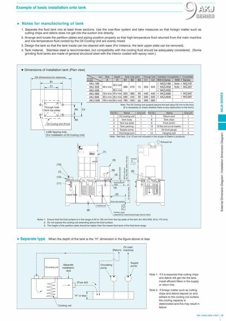
Note 1. If it is expected that cutting chips and debris will get into the tank, install efficient filters in the supply or return line.
Note 2. If foreign matter such as cutting chips and debris deposit on and adhere to the cooling coil surface, the cooling capacity is deteriorated and this may result in failure.
Notes 1:2:3:
Ensure that the fluid surface is in the range of 40 to 100 mm from the top plate of the tank (for AKJ1509, 40 to 170 mm).Do not expose the cooling coil extending above the fluid surface.The height of the partition plate should be higher than the lowest fluid level of the fluid level range
● Separate type When the depth of the tank is the “H” dimension in the figure above or less
Oil cooling unitSeparate
installation tank
Circulating pump
Supply pump
(Return)(To main machine)
Cooling coil
“H” or less
(Free fall)
Suction air
Exhaust air
(From tank bottom)
(Liquid surface range)
With
in 1
00 m
m(f
or A
KJ1
509,
with
in 1
70 m
m)
40 m
m o
r m
ore
50 m
m
or m
ore
H m
m o
r m
ore
Partition plate(required for machining through hole for drain)
Liquid flow
Cooling coil
(10)
(7)
(12)
(11)
(1)
(5)
(9)
(3)(6)
(4)
(2)
(8)
Note: The Oil Cooling Unit projects beyond the tank about 50 mm to the front.(It is necessary to check whether there is any obstruction to the front.)
Oil Cooling Unit series
AKJ 189AKJ 359AKJ 459 AKJ 569AKJ 909AKJ1509
Note: AKZJ187Note: AKZJ357
AKZJ567 AKZJ907
Part No. Name Q’ty/unit1 Oil cooling unit 12 Tank body 13 Tank top plate 14 Tank packing 15 Supply pump 16 Discharge port 1
Note: Part Nos. 2 to 12 are not included in the scope of Daikin’s products.
7 Return port 18 Tank drain 19 Float switch 1
10 Oil filler port-cum-air breather 111 Oil level gauge 112 Hanging bolt 4
Part No. Name Q’ty/unit
Note: Refer to Page 5 for more details.
AK
J9 S
ER
IES
Ext
erna
l Dim
ensi
on D
iagr
am /
Inst
alla
tion
Dim
ensi
on D
iagr
am
18 Model name nameplate
19 Heater
Part No. Name Description
11 Machine nameplate12 Design nameplate13 Overall caution plate14 Electric schematic diagram nameplate15 Battery charge mark nameplate16 Cutting injury caution nameplate
Part No. Name Description
1 Control panel2 Electrical component box lid
3 Power supply inlet (Right / Left)
4Signal line inlet (Right / Left)
5 Eye plate6 Air filter7 Room temperature thermistor8 Fluid temperature thermistor9 Cooling coil
Only for models with heater
20 Power supply inletφ28-mm hole For different voltage options -047, -048 only10 Agitating plate
φ22 hole
φ28-mm hole Except for different voltage options −047, −048
φ25 hole17 High temperature caution nameplate
● For the machining dimensions of the holes for installation on the tank, refer to page 12.
Through hole (Tank top plate)
1. Separate the fluid tank into at least three sections. Use the over-flow system and take measures so that foreign matter such as cutting chips and debris does not get into the suction line directly.
2. Arrange and locate the partition plates and piping position properly so that high-temperature fluid returned from the main machine and low-temperature fluid cooled by the Oil Cooling Unit are evenly mixed.
3. Design the tank so that the tank inside can be cleaned with ease (For instance, the tank upper plate can be removed).
4. Tank material: Stainless steel is recommended, but compatibility with the cooling fluid should be adequately considered. (Some grinding fluid tanks are made of general structural steel with the interior coated with epoxy resin.)
● Notes for manufacturing of tank
● Dimensions of installation tank (Plan view)
External Dimension Diagram
AKJ909 (-B, -C, -H, -046, -047, -048)
The positions of the bolt holes used for installing the product on the tank top plate are compatible with the AKZJ8 series, but the positions of the power supply/signal cable inlet ports are not.
Example of basic installation onto tank 9AKJSERIES
415
1200
1615
(166
5)
(50)
5901056015
610
9044
062
0
(100
)(1
110)
Suction air
50
Minimum fluid level
Tank bottom surface
(545)
(311)
(122
5)
(505
)
(230)
38 Exhaust air
4-φ10 Installation hole
Min
.
Max
.
Rear face
Inside face
Rear face
Rear face
(15)(16)(17)
(13)(14)
(12) (18)(5)(2)(1)
(7)(6)
(3)
(3)
(4)
(4)
(11)
(10)(19)
(9)
(8)
AKJ1509 (-B, -C, -H, -046, -047, -048)
18 Model name nameplate
19 Heater
Part No. Name Description
11 Machine faceplate12 Design nameplate13 Overall caution plate14 Electric schematic diagram faceplate15 Battery charge mark nameplate16 Cutting injury caution nameplate
Part No. Name Description
1 Control panel2 Electrical component box lid
3 Power supply inlet (Right / Left)
4Signal line inlet (Right / Left)
5 Eye plate6 Air filter7 Room temperature thermistor8 Fluid temperature thermistor9 Cooling coil
Only for models with heater
20 Power supply inlet
φ28-mm hole For different voltage options -047, -048 only10 Agitating plate
φ22 hole
φ28-mm hole Except for different voltage options −047, −048
φ25 hole17 High temperature caution nameplate
78015
73522
115
500
725
4-φ10 Installation hole
Rear face
(15)(16)(17)
(13)(14)
810
Inside face(12) (18)(5)
(5)
(2)(1)
(7)(6)
515
1445
1960
(200
7)
(50)
Tank bottom surface
Min
.
Suction air
(653)(365)
38
Exhaust air
(146
9)
(135
4)50
Rear face
Rear face
(3)
(3)
(4)
(4)
(11)
(170
)
Minimum fluid levelMax
.
(10)
(19)
(9)
(8)
(20)
(67)
(179)
(20)
1211
TankA H B1 B3 C1
Size Depth Tank hole pitch Through hole Installation Compatibility (: Compatible)C2
32515 325
440 440500
270
380440
390
500590
600 or more
700 or more800 or more
1000 or more
395 or more
340 or more
465 or more400 or more
500560500780565 or more 560
With 8 Series With 7 Series AKZJ188 AKZJ358 AKZJ458 AKZJ568 AKZJ908
453030
–
––
B2
B2 C2
C1
4-M8 Tapping hole (For installation of Oil Cooling Unit)
B1
A (Dimensions for reference)
B3
Oil Cooling Unit (Front)
Note 1. If it is expected that cutting chips and debris will get into the tank, install efficient filters in the supply or return line.
Note 2. If foreign matter such as cutting chips and debris deposit on and adhere to the cooling coil surface, the cooling capacity is deteriorated and this may result in failure.
Notes 1:2:3:
Ensure that the fluid surface is in the range of 40 to 100 mm from the top plate of the tank (for AKJ1509, 40 to 170 mm).Do not expose the cooling coil extending above the fluid surface.The height of the partition plate should be higher than the lowest fluid level of the fluid level range
● Separate type When the depth of the tank is the “H” dimension in the figure above or less
Oil cooling unitSeparate
installation tank
Circulating pump
Supply pump
(Return)(To main machine)
Cooling coil
“H” or less
(Free fall)
Suction air
Exhaust air
(From tank bottom)
(Liquid surface range)
With
in 1
00 m
m(f
or A
KJ1
509,
with
in 1
70 m
m)
40 m
m o
r m
ore
50 m
m
or m
ore
H m
m o
r m
ore
Partition plate(required for machining through hole for drain)
Liquid flow
Cooling coil
(10)
(7)
(12)
(11)
(1)
(5)
(9)
(3)(6)
(4)
(2)
(8)
Note: The Oil Cooling Unit projects beyond the tank about 50 mm to the front.(It is necessary to check whether there is any obstruction to the front.)
Oil Cooling Unit series
AKJ 189AKJ 359AKJ 459 AKJ 569AKJ 909AKJ1509
Note: AKZJ187Note: AKZJ357
AKZJ567 AKZJ907
Part No. Name Q’ty/unit1 Oil cooling unit 12 Tank body 13 Tank top plate 14 Tank packing 15 Supply pump 16 Discharge port 1
Note: Part Nos. 2 to 12 are not included in the scope of Daikin’s products.
7 Return port 18 Tank drain 19 Float switch 1
10 Oil filler port-cum-air breather 111 Oil level gauge 112 Hanging bolt 4
Part No. Name Q’ty/unit
Note: Refer to Page 5 for more details.
AK
J9 S
ER
IES
Ext
erna
l Dim
ensi
on D
iagr
am /
Inst
alla
tion
Dim
ensi
on D
iagr
am
18 Model name nameplate
19 Heater
Part No. Name Description
11 Machine faceplate12 Design nameplate13 Overall caution plate14 Electric schematic diagram faceplate15 Battery charge mark nameplate16 Cutting injury caution nameplate
Part No. Name Description
1 Control panel2 Electrical component box lid
3 Power supply inlet (Right / Left)
4Signal line inlet (Right / Left)
5 Eye plate6 Air filter7 Room temperature thermistor8 Fluid temperature thermistor9 Cooling coil
Only for models with heater
20 Power supply inletφ28-mm hole For different voltage options -047, -048 only10 Agitating plate
φ22 hole
φ28-mm hole Except for different voltage options −047, −048
φ25 hole17 High temperature caution nameplate
● For the machining dimensions of the holes for installation on the tank, refer to page 12.
Through hole (Tank top plate)
1. Separate the fluid tank into at least three sections. Use the over-flow system and take measures so that foreign matter such as cutting chips and debris does not get into the suction line directly.
2. Arrange and locate the partition plates and piping position properly so that high-temperature fluid returned from the main machine and low-temperature fluid cooled by the Oil Cooling Unit are evenly mixed.
3. Design the tank so that the tank inside can be cleaned with ease (For instance, the tank upper plate can be removed).
4. Tank material: Stainless steel is recommended, but compatibility with the cooling fluid should be adequately considered. (Some grinding fluid tanks are made of general structural steel with the interior coated with epoxy resin.)
● Notes for manufacturing of tank
● Dimensions of installation tank (Plan view)
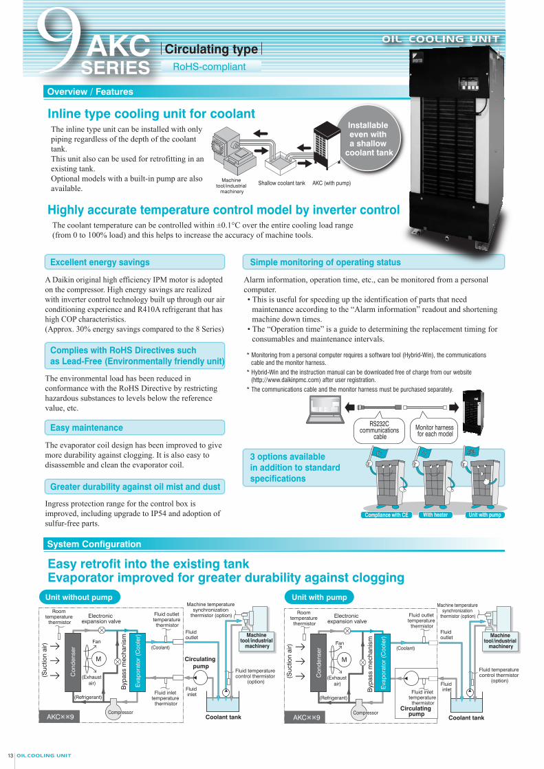
Excellent energy savings
Complies with RoHS Directives such as Lead-Free (Environmentally friendly unit)
Easy maintenance
Greater durability against oil mist and dust
3 options available in addition to standard specifications
Simple monitoring of operating status
Oil cooling unit horsepower (HP) 1.2
AKC359
1.44 kW/5.3 A
1.60 kW/5.5 A
1.60 kW/5.2 A
1.17 kW/4.2 A
1.22 kW/4.3 A
1.19 kW/3.5 A
1.19 kW/3.5 A
1.43 kW/3.9 A
1.21 kW/4.1 A
Equivalent to 0.75 kW
−C (CE compliant type) −C (CE compliant type)−H (With heater) −200 (With pump)Cooling capacity (50/60 Hz)*1 kW
kW
200 V 50 Hz
200 V 60 Hz
220 V 60 Hz
mm
K
°C
°C
°C
L/min
kg
Heater
Supply power*2
Exterior color
External dimensions (H × W × D)
Compressor (Hermetic DC swing type)
Evaporator
Condenser
Propeller fan Motor
Refrigerant control
Ingress protection*9
Items prepared by the customer
Refrigerant (R410A) *5 Filling amount
Usable fluids *6
dB (A)
Protection devices/protective functions
Fluid temperature controller resolution
Capacity control range
Timer function
Temperature control (Selectable)
Fixe
d ty
pe
Standard
Synchronization range
Object to be controlled
Range
Pump
Motor
Total head (standard point, 50/60 Hz)
Main circuit
Operation circuitPower voltage
Model name
Operation range
Circulating volumeRated circulating volume
Fluid inlet temperature
Room temperature
Fluid inlet
AMolded-case circuit breaker (Rated current)
Standard
995 × 450 × 560
10
86kgMass 10583
0.4 kW-2P
10/15 m
––
Fluid outlet
Permissible transport vibration
1
54 W
0.80
62
Circulating pump –
Sync
hroniz
ation
type
Object to be controlled
Suction lift 0.5 m*3–
3.5/3.5 3.2/3.2
L/min
mm2/sWithstanding pressureFluid viscosity
MPa
Fluid drain portConnecting tube
Priming port *7
– Rc3/8
2.0
AKC569
2.10 kW/7.4 A
2.30 kW/7.6 A
2.30 kW/7.3 A
1.78 kW/6.2 A
1.87 kW/6.3 A
1.86 kW/6.1 A
Equivalent to 1.5 kW
−H (With heater) −200 (With pump)Standard
2.34 kW/7.0 A
2.34 kW/7.0 A
2.81 kW/7.6 A
1,200 × 470 × 670
15
106 122100
0.4 kW-2P
10/15 m
–
–
– 2
100 W
1.25
65
Circulating pump –
0.5 m*3–
5.6/5.6 5.3/5.3
– Rc1/2Oil pan drain
– – –
––
–
––
–
––
–
––
–
5 to 45
5 to 50
35
15 minimum
Lubrication oil, hydraulic oil, cutting oil, (water soluble) coolant, (grinding oil *6) (Use clean fluid that can pass through filter equipment with a 40-mesh or finer screen.)
Rc1
Rc3/4
Rc3/4
A set of overcurrent relay (for a pump motor), discharge pipe temperature thermostat, condenser temperature thermostat, reverse-phase protection device, restart prevention timer, low room temperature protection thermostat, high fluid temperature protection thermostat, low fluid temperature protection thermostat, refrigerant leakage detector, evaporator clogging detection (intake pipe temperature thermostat), inverter protection device, circuit breaker, temperature fuse (-H type only), overheat prevention temperature switch (-H type only), high pressure switch (-C type only), and compressor thermal protector (-C type only)
200 maximum (water soluble to ISO VG32)
0.2
Rc1/2
Room temperature or machine temperature *4 (Set to “Room temperature: Mode 3” by default)
Fluid inlet temperature or fluid outlet temperature (Set to fluid inlet temperature by default)
−9.9 to 9.9 against the reference temperature (Set at 0.0 by default)
Fluid inlet temperature or fluid outlet temperature
5 to 50
Compressor revolutions by inverter + Opening of electric expansion valve
ON timer: 1 to 999 hours (1-hour unit setting)
0 to 100%
±0.1°C
Three-phase 200/200220 VAC 50/60 Hz
Three-phase 200/200220 VAC 50/60 Hz
DC12/24 V
Note:
Ivory white
Shell-end coil type
Cross-fin-coil type
Up and down vibration 14.7 m/S2 × 2.5 hr (7.5 to 100 Hz sweep/5 min.)
IP2X
−AKC1 2
3
94
Highly accurate temperature control model by inverter control
Overview / Features
9AKCSERIES
Easy retrofit into the existing tankEvaporator improved for greater durability against clogging
With heater Unit with pumpCompliance with CE
HC 200
Alarm information, operation time, etc., can be monitored from a personal computer.• This is useful for speeding up the identification of parts that need
maintenance according to the “Alarm information” readout and shortening machine down times.
• The “Operation time” is a guide to determining the replacement timing for consumables and maintenance intervals.
* Monitoring from a personal computer requires a software tool (Hybrid-Win), the communications cable and the monitor harness.
* Hybrid-Win and the instruction manual can be downloaded free of charge from our website (http://www.daikinpmc.com) after user registration.
* The communications cable and the monitor harness must be purchased separately.
Installable even with a shallow
coolant tank
Shallow coolant tank AKC (with pump)Machine tool/industrial
machinery
System Configuration
Nomenclature
Specifications
A Daikin original high efficiency IPM motor is adopted on the compressor. High energy savings are realized with inverter control technology built up through our air conditioning experience and R410A refrigerant that has high COP characteristics. (Approx. 30% energy savings compared to the 8 Series)
The environmental load has been reduced in conformance with the RoHS Directive by restricting hazardous substances to levels below the reference value, etc.
The evaporator coil design has been improved to give more durability against clogging. It is also easy to disassemble and clean the evaporator coil.
Ingress protection range for the control box is improved, including upgrade to IP54 and adoption of sulfur-free parts.
RS232C communications
cableMonitor harness for each model
AKC9
Electronic expansion valve
(Suc
tion
air)
Compressor
(Refrigerant)
Circulating pump
Fluid inlet
Fluid outlet
(Coolant)
Coolant tank
Machine tool/industrial
machinery
Fluid outlet temperature
thermistor
Room temperature
thermistor
Fluid inlet temperature
thermistor
Fluid temperature control thermistor
(option)
Machine temperature synchronization
thermistor (option)
M
Fan
(Exhaust air)
Byp
ass
mec
hani
sm
Circulating pump
Machine tool/industrial
machinery
Machine temperature synchronization
thermistor (option)
AKC9
Electronic expansion valve
(Suc
tion
air)
Compressor
(Refrigerant)
Fluid inlet
Fluid outlet
(Coolant)
Coolant tank
Eva
pora
tor
(Coo
ler)
Eva
pora
tor
(Coo
ler)
Fluid outlet temperature
thermistor
Room temperature
thermistor
Fluid inlet temperature
thermistor
Fluid temperature control thermistor
(option)
M
Fan
(Exhaust air)
Byp
ass
mec
hani
sm
Con
dens
er
Con
dens
er
Unit without pump Unit with pump
Inline type cooling unit for coolant
The coolant temperature can be controlled within ±0.1°C over the entire cooling load range (from 0 to 100% load) and this helps to increase the accuracy of machine tools.
1 Oil cooling unit identification codeOptions and their combinations
2
AKC: High-accuracy inverter controlled oil cooling unit [Coolant circulating type]
Symbol of series (Symbol to represent model change)9: “9” series
3
Cooling capacity35: Cooling capacity of 3.5 kW 56: Cooling capacity of 5.6 kW
4 Symbol of option type (C/H/200)/Non-standard number
Special specifications (different voltages, with casters, etc.)- ∗ ∗ ∗ (3 numerical digits), C ∗ ∗ ∗ (3 numerical digits), etc.Please consult us separately about special specifications.
−C − −−H − −−200 − −
−CH −C200 −
H200 −
K200
Option Symbol Compliance with CE With heater Unit with pump
The inline type unit can be installed with only piping regardless of the depth of the coolant tank.This unit also can be used for retrofitting in an existing tank. Optional models with a built-in pump are also available.
Maximum power consumption Maximum current consumption
When cooling
When heating
200 V 50 Hz
200 V 60 Hz
220 V 60 Hz
Noise level *8 (Value measured at 1m high in front, value equivalent as measured in anechoic chamber)
*1. The cooling capacity indicates the value at the standard point (fluid inlet temperature: 35°C, room temperature: 35°C, fluid used: ISO VG32, flow rate: rated circulating volume). This unit has about ±5% of product tolerance.*2. Use a commercial power supply for the power source. The use of an inverter power supply may cause burn damage to the unit.
The voltage fluctuation range should be within ±10%. If it is more than ±10%, please consult us.*3. Indicates the maximum value with clean fresh water.*4. The optional thermistor for machine temperature synchronization is required.*5. The SDS (Safety Data Sheet) of refrigerant R410A is attached to the –C type.*6. If the unit is used for a grinding machine or similar equipment, the evaporator tends to become clogged with foreign material,
necessitating frequent maintenance of the evaporator or leading to significantly shorter pump service life due to wear of the pump parts (mainly the mechanical seals).This unit is cannot be used for water, chemicals, foods or fuels.
*7. Not applicable to models without a pump*8. The rotational speed of the fan varies depending on the room temperature to conserve energy. Therefore, it is normal for its operating sound to vary accordingly.*9. Ingress protection for switch box: equivalent to IP54 (When wired with IP54 or higher conduit tube or other protection on the wiring port.) 1413
AK
C9
SE
RIE
SO
verv
iew
/Fea
ture
s / S
yste
m C
onfig
urat
ion
/ Nom
encl
atur
e / S
peci
ficat
ions
Circulating typeRoHS-compliant
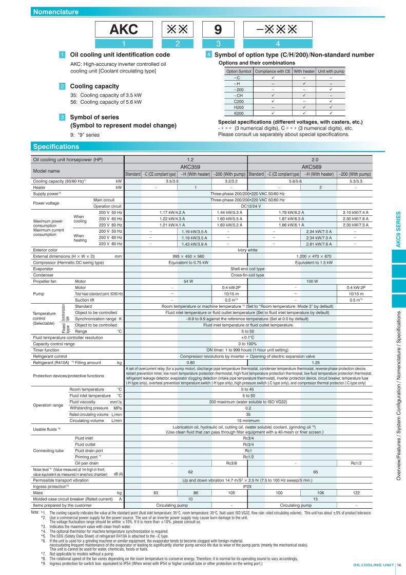
Excellent energy savings
Complies with RoHS Directives such as Lead-Free (Environmentally friendly unit)
Easy maintenance
Greater durability against oil mist and dust
3 options available in addition to standard specifications
Simple monitoring of operating status
Oil cooling unit horsepower (HP) 1.2
AKC359
1.44 kW/5.3 A
1.60 kW/5.5 A
1.60 kW/5.2 A
1.17 kW/4.2 A
1.22 kW/4.3 A
1.19 kW/3.5 A
1.19 kW/3.5 A
1.43 kW/3.9 A
1.21 kW/4.1 A
Equivalent to 0.75 kW
−C (CE compliant type) −C (CE compliant type)−H (With heater) −200 (With pump)Cooling capacity (50/60 Hz)*1 kW
kW
200 V 50 Hz
200 V 60 Hz
220 V 60 Hz
mm
K
°C
°C
°C
L/min
kg
Heater
Supply power*2
Exterior color
External dimensions (H × W × D)
Compressor (Hermetic DC swing type)
Evaporator
Condenser
Propeller fan Motor
Refrigerant control
Ingress protection*9
Items prepared by the customer
Refrigerant (R410A) *5 Filling amount
Usable fluids *6
dB (A)
Protection devices/protective functions
Fluid temperature controller resolution
Capacity control range
Timer function
Temperature control (Selectable)
Fixe
d ty
pe
Standard
Synchronization range
Object to be controlled
Range
Pump
Motor
Total head (standard point, 50/60 Hz)
Main circuit
Operation circuitPower voltage
Model name
Operation range
Circulating volumeRated circulating volume
Fluid inlet temperature
Room temperature
Fluid inlet
AMolded-case circuit breaker (Rated current)
Standard
995 × 450 × 560
10
86kgMass 10583
0.4 kW-2P
10/15 m
––
Fluid outlet
Permissible transport vibration
1
54 W
0.80
62
Circulating pump –
Sync
hroniz
ation
type
Object to be controlled
Suction lift 0.5 m*3–
3.5/3.5 3.2/3.2
L/min
mm2/sWithstanding pressureFluid viscosity
MPa
Fluid drain portConnecting tube
Priming port *7
– Rc3/8
2.0
AKC569
2.10 kW/7.4 A
2.30 kW/7.6 A
2.30 kW/7.3 A
1.78 kW/6.2 A
1.87 kW/6.3 A
1.86 kW/6.1 A
Equivalent to 1.5 kW
−H (With heater) −200 (With pump)Standard
2.34 kW/7.0 A
2.34 kW/7.0 A
2.81 kW/7.6 A
1,200 × 470 × 670
15
106 122100
0.4 kW-2P
10/15 m
–
–
– 2
100 W
1.25
65
Circulating pump –
0.5 m*3–
5.6/5.6 5.3/5.3
– Rc1/2Oil pan drain
– – –
––
–
––
–
––
–
––
–
5 to 45
5 to 50
35
15 minimum
Lubrication oil, hydraulic oil, cutting oil, (water soluble) coolant, (grinding oil *6) (Use clean fluid that can pass through filter equipment with a 40-mesh or finer screen.)
Rc1
Rc3/4
Rc3/4
A set of overcurrent relay (for a pump motor), discharge pipe temperature thermostat, condenser temperature thermostat, reverse-phase protection device, restart prevention timer, low room temperature protection thermostat, high fluid temperature protection thermostat, low fluid temperature protection thermostat, refrigerant leakage detector, evaporator clogging detection (intake pipe temperature thermostat), inverter protection device, circuit breaker, temperature fuse (-H type only), overheat prevention temperature switch (-H type only), high pressure switch (-C type only), and compressor thermal protector (-C type only)
200 maximum (water soluble to ISO VG32)
0.2
Rc1/2
Room temperature or machine temperature *4 (Set to “Room temperature: Mode 3” by default)
Fluid inlet temperature or fluid outlet temperature (Set to fluid inlet temperature by default)
−9.9 to 9.9 against the reference temperature (Set at 0.0 by default)
Fluid inlet temperature or fluid outlet temperature
5 to 50
Compressor revolutions by inverter + Opening of electric expansion valve
ON timer: 1 to 999 hours (1-hour unit setting)
0 to 100%
±0.1°C
Three-phase 200/200220 VAC 50/60 Hz
Three-phase 200/200220 VAC 50/60 Hz
DC12/24 V
Note:
Ivory white
Shell-end coil type
Cross-fin-coil type
Up and down vibration 14.7 m/S2 × 2.5 hr (7.5 to 100 Hz sweep/5 min.)
IP2X
−AKC1 2
3
94
Highly accurate temperature control model by inverter control
Overview / Features
9AKCSERIES
Easy retrofit into the existing tankEvaporator improved for greater durability against clogging
With heater Unit with pumpCompliance with CE
HC 200
Alarm information, operation time, etc., can be monitored from a personal computer.• This is useful for speeding up the identification of parts that need
maintenance according to the “Alarm information” readout and shortening machine down times.
• The “Operation time” is a guide to determining the replacement timing for consumables and maintenance intervals.
* Monitoring from a personal computer requires a software tool (Hybrid-Win), the communications cable and the monitor harness.
* Hybrid-Win and the instruction manual can be downloaded free of charge from our website (http://www.daikinpmc.com) after user registration.
* The communications cable and the monitor harness must be purchased separately.
Uninstallable even with a shallow
coolant tank
Shallow coolant tank AKC (with pump)Machine tool/industrial
machinery
System Configuration
Nomenclature
Specifications
A Daikin original high efficiency IPM motor is adopted on the compressor. High energy savings are realized with inverter control technology built up through our air conditioning experience and R410A refrigerant that has high COP characteristics. (Approx. 30% energy savings compared to the 8 Series)
The environmental load has been reduced in conformance with the RoHS Directive by restricting hazardous substances to levels below the reference value, etc.
The evaporator coil design has been improved to give more durability against clogging. It is also easy to disassemble and clean the evaporator coil.
Ingress protection range for the control box is improved, including upgrade to IP54 and adoption of sulfur-free parts.
RS232C communications
cableMonitor harness for each model
AKC9
Electronic expansion valve
(Suc
tion
air)
Compressor
(Refrigerant)
Circulating pump
Fluid inlet
Fluid outlet
(Coolant)
Coolant tank
Machine tool/industrial
machinery
Fluid outlet temperature
thermistor
Room temperature
thermistor
Fluid inlet temperature
thermistor
Fluid temperature control thermistor
(option)
Machine temperature synchronization
thermistor (option)
M
Fan
(Exhaust air)
Byp
ass
mec
hani
sm
Circulating pump
Machine tool/industrial
machinery
Machine temperature synchronization
thermistor (option)
AKC9
Electronic expansion valve
(Suc
tion
air)
Compressor
(Refrigerant)
Fluid inlet
Fluid outlet
(Coolant)
Coolant tank
Eva
pora
tor
(Coo
ler)
Eva
pora
tor
(Coo
ler)
Fluid outlet temperature
thermistor
Room temperature
thermistor
Fluid inlet temperature
thermistor
Fluid temperature control thermistor
(option)
M
Fan
(Exhaust air)
Byp
ass
mec
hani
sm
Con
dens
er
Con
dens
er
Unit without pump Unit with pump
Inline type cooling unit for coolant
The coolant temperature can be controlled within ±0.1°C over the entire cooling load range (from 0 to 100% load) and this helps to increase the accuracy of machine tools.
1 Oil cooling unit identification codeOptions and their combinations
2
AKC: High-accuracy inverter controlled oil cooling unit [Coolant circulating type]
Symbol of series (Symbol to represent model change)9: “9” series
3
Cooling capacity35: Cooling capacity of 3.5 kW 56: Cooling capacity of 5.6 kW
4 Symbol of option type (C/H/200)/Non-standard number
Special specifications (different voltages, with casters, etc.)- ∗ ∗ ∗ (3 numerical digits), C ∗ ∗ ∗ (3 numerical digits), etc.Please consult us separately about special specifications.
−C − −−H − −−200 − −
−CH −C200 −
H200 −
K200
Option Symbol Compliance with CE With heater Unit with pump
The inline type unit can be installed with only piping regardless of the depth of the coolant tank.This unit also can be used for retrofitting in an existing tank. Optional models with a built-in pump are also available.
Maximum power consumption Maximum current consumption
When cooling
When heating
200 V 50 Hz
200 V 60 Hz
220 V 60 Hz
Noise level *8 (Value measured at 1m high in front, value equivalent as measured in anechoic chamber)
*1. The cooling capacity indicates the value at the standard point (fluid inlet temperature: 35°C, room temperature: 35°C, fluid used: ISO VG32, flow rate: rated circulating volume). This unit has about ±5% of product tolerance.*2. Use a commercial power supply for the power source. The use of an inverter power supply may cause burn damage to the unit.
The voltage fluctuation range should be within ±10%. If it is more than ±10%, please consult us.*3. Indicates the maximum value with clean fresh water.*4. The optional thermistor for machine temperature synchronization is required.*5. The SDS (Safety Data Sheet) of refrigerant R410A is attached to the –C type.*6. If the unit is used for a grinding machine or similar equipment, the evaporator tends to become clogged with foreign material,
necessitating frequent maintenance of the evaporator or leading to significantly shorter pump service life due to wear of the pump parts (mainly the mechanical seals).This unit is cannot be used for water, chemicals, foods or fuels.
*7. Not applicable to models without a pump*8. The rotational speed of the fan varies depending on the room temperature to conserve energy. Therefore, it is normal for its operating sound to vary accordingly.*9. Ingress protection for switch box: equivalent to IP54 (When wired with IP54 or higher conduit tube or other protection on the wiring port.) 1413
AK
C9
SE
RIE
SO
verv
iew
/Fea
ture
s / S
yste
m C
onfig
urat
ion
/ Nom
encl
atur
e / S
peci
ficat
ions
Circulating typeRoHS-compliant

1. The symbols indicate standard points. (Room temperature: 35°C, inlet fluid temperature: 35°C, flow rate: 35 L/min., fluid used: ISO VG32)
1. The symbols indicate standard points. (Room temperature: 35°C, inlet fluid temperature: 35°C, flow rate: 35 L/min., fluid used: ISO VG32)
For the selection of the oil pump size and piping system, such as diameter and length of pipes, refer to the chart below. Pay attention to making the oil flow rate 15 L/min or greater.
The chart below shows the flow rate characteristics of the pumps with the internal pressure loss taken into account. Select the diameters and lengths of pipes by referring to the chart below so that a circulating volume of 15 L/min or greater can be maintained.
Pum
p he
ad (
m)
5
Flow rate (L/min)
2
0
16
14
12
10
8
4
6
Water (60 Hz)
4010 20 30 50: 60 70
Pum
p he
ad (
m)
5
Flow rate (L/min)
2
0
16
14
12
10
8
4
6
75 mm2/s Oil
Water
4010 20 30 50 60 70
Water (50 Hz)
75 mm2/s Oil (60 Hz)
75 mm2/s Oil (50 Hz)
(Internal pressure loss included)
Solid lines : AKC569、AKC569-C、AKC569-H
Minimum operating flow rate (15 L/min)
Minimum operating flow rate (15 L/min)
AKC359
AKC569
Solid lines : AKC359、AKC359-C、AKC359-HC
oolin
g ca
paci
ty (
W)
255 10 15 20 30 35 40 45
Room temperature (°C)
500
0
4,000
3,500
3,000
2,500
2,000
1,000
1,500
Fluid inlet temperature = Room temperature + 10°C
Fluid inlet temperature = Room temperature
Fluid inlet temperature = Room temperature – 10°C
Coo
ling
capa
city
(W
)
255 10 15 20 30 35 40 45
Room temperature (°C)
1,000
0
7,000
6,000
5,000
4,000
2,000
3,000
Fluid inlet temperature = Room temperature + 10°C
Fluid inlet temperature = Room temperature
Fluid inlet temperature = Room temperature – 10°C
2. The cooling capacity varies depending on the room temperature, fluid temperature, the kinematic viscosity of the fluid, etc.
2. The cooling capacity varies depending on the room temperature, fluid temperature, the kinematic viscosity of the fluid, etc.
Broken lines : AKC359-200
Broken lines : AKC569-200
AK
C9
SE
RIE
SC
oolin
g C
apac
ity C
hara
cter
istic
Cha
rt /
Inte
rnal
Pre
ssur
e Lo
ss /
Flow
Rat
e C
hara
cter
istic
s fo
r M
odel
s W
ith a
Pum
p / E
xter
nal D
imen
sion
Dia
gram
15 16
Internal Pressure Loss
AKC359 (-C) (-H) (-200)
AKC569 (-C) (-H) (-200)
1819
Part No. Name Description
11 Room temperature thermistor121314 Instruction nameplate1516
Cutting injury caution nameplate
Part No.
Name Description
1 Fluid inlet2 Fluid outlet
3 Fluid drain port4 PRIMING*5 Control panel6 Electrical component box lid7 Power supply inlet (Right / Left)8 Signal line inlet (Right / Left)9 Eye plate
2010 Air filter
Rc3/4Rc3/4
Rc1 PluggedRc1/2 Plugged
17
18
Model name nameplate
19
Part No. Name Description
11
Machine nameplate
12
Design nameplate
13
Overall caution plate
14
Electric schematic diagram nameplate
15
Battery charge mark nameplate
16
Part No. Name Description
12
3456789
20
21
21
10
φ22 Hole
φ25 Hole
φ28 Hole
17
High temperature caution nameplate
Suction air
Exhaust air WIRE-ROPE OR NYLON-SLING
400 mm
or more
Opposite side
Opposite side (7)
(576
)
(461)(15)(16)
(17)
(13)
(12)
(18)
(5)
(2)(1)
(6)
(7)
(3)(4)
(11)
(19)
(20)
(9)
(10)
(8)
(8)(14)
Inside face
995
(125
0)
1200
(107
0)90
(122
5)
264
200
157
(864
)90
(101
9)
264
200
157
(18)
(18)470433 20
(12)
38 (597)(324)
110225
332630670
(104
5)
415 520
(12)
56020
38 (487)
90205
295
(239)
450
4-φ13 HOLE(FOR MOUNTING BOLT)
Room temperature thermistor
Instruction nameplate
Cutting injury caution nameplate
Fluid inletFluid outlet
Fluid drain portPRIMING*Control panelElectrical component box lidPower supply inlet (Right / Left)Signal line inlet (Right / Left)Eye plateAir filter
Rc3/4Rc3/4Rc1 Plugged
Rc1/2 with PLUG
Rc1/2 with PLUG Models with a pump only
Model name nameplate
Oil pan drain*
Machine nameplateDesign nameplate
Overall caution plateElectric schematic diagram nameplateBattery charge mark nameplate
φ22 Hole
φ25 Hole
φ28 Hole
High temperature caution nameplate(686
)
(479)
(15)(16)
(17)(18)
(19)
(7)
(13)
(12)
(5)
(2)
(1)
(6)
(7)
(3)
(4)
(11)
(20)
(9)
(10)
(8)
(8)
(14)Suction air
Exhaust airWIRE-ROPE OR NYLON-SLING
500 mm
or more
Opposite side
Opposite side
Rear face
Inside face
4-φ13 HOLE (FOR MOUNTING BOLT)
Rc3/8 with PLUG Models with a pump only
Oil pan drain*
Flow Rate Characteristics for Models With a Pump
Cooling Capacity Characteristic Chart 9AKCSERIES
Note: Refer to Page 5 for more details.● For the machining dimensions of the holes for installation on the tank, refer to page 12.
External Dimension Diagram 9AKCSERIES
*Models other than those with a pump cannot be used.
*Models other than those with a pump cannot be used.
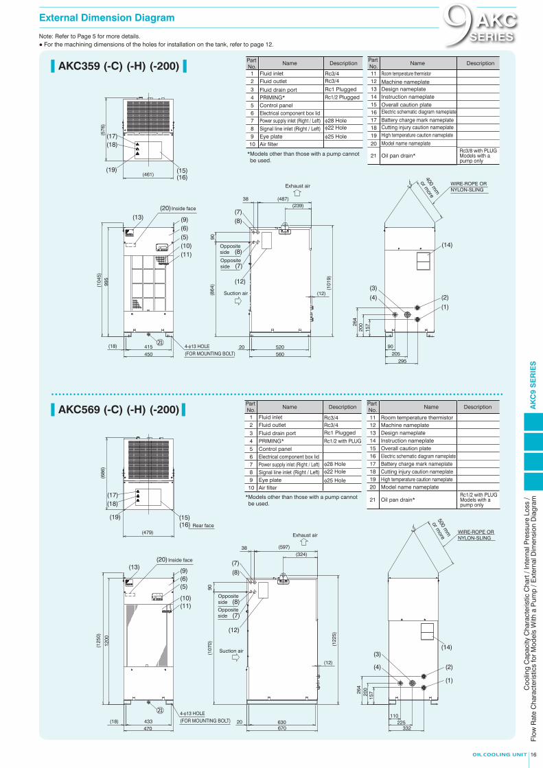
1. The symbols indicate standard points. (Room temperature: 35°C, inlet fluid temperature: 35°C, flow rate: 35 L/min., fluid used: ISO VG32)
1. The symbols indicate standard points. (Room temperature: 35°C, inlet fluid temperature: 35°C, flow rate: 35 L/min., fluid used: ISO VG32)
For the selection of the oil pump size and piping system, such as diameter and length of pipes, refer to the chart below. Pay attention to making the oil flow rate 15 L/min or greater.
The chart below shows the flow rate characteristics of the pumps with the internal pressure loss taken into account. Select the diameters and lengths of pipes by referring to the chart below so that a circulating volume of 15 L/min or greater can be maintained.
Pum
p he
ad (
m)
5
Flow rate (L/min)
2
0
16
14
12
10
8
4
6
Water (60 Hz)
4010 20 30 50: 60 70
Pum
p he
ad (
m)
5
Flow rate (L/min)
2
0
16
14
12
10
8
4
6
75 mm2/s Oil
Water
4010 20 30 50 60 70
Water (50 Hz)
75 mm2/s Oil (60 Hz)
75 mm2/s Oil (50 Hz)
(Internal pressure loss included)
Solid lines : AKC569、AKC569-C、AKC569-H
Minimum operating flow rate (15 L/min)
Minimum operating flow rate (15 L/min)
AKC359
AKC569
Solid lines : AKC359、AKC359-C、AKC359-HC
oolin
g ca
paci
ty (
W)
255 10 15 20 30 35 40 45
Room temperature (°C)
500
0
4,000
3,500
3,000
2,500
2,000
1,000
1,500
Fluid inlet temperature = Room temperature + 10°C
Fluid inlet temperature = Room temperature
Fluid inlet temperature = Room temperature – 10°C
Coo
ling
capa
city
(W
)
255 10 15 20 30 35 40 45
Room temperature (°C)
1,000
0
7,000
6,000
5,000
4,000
2,000
3,000
Fluid inlet temperature = Room temperature + 10°C
Fluid inlet temperature = Room temperature
Fluid inlet temperature = Room temperature – 10°C
2. The cooling capacity varies depending on the room temperature, fluid temperature, the kinematic viscosity of the fluid, etc.
2. The cooling capacity varies depending on the room temperature, fluid temperature, the kinematic viscosity of the fluid, etc.
Broken lines : AKC359-200
Broken lines : AKC569-200
AK
C9
SE
RIE
SC
oolin
g C
apac
ity C
hara
cter
istic
Cha
rt /
Inte
rnal
Pre
ssur
e Lo
ss /
Flow
Rat
e C
hara
cter
istic
s fo
r M
odel
s W
ith a
Pum
p / E
xter
nal D
imen
sion
Dia
gram
15 16
Internal Pressure Loss
AKC359 (-C) (-H) (-200)
AKC569 (-C) (-H) (-200)
1819
Part No. Name Description
11 Room temperature thermistor121314 Instruction nameplate1516
Cutting injury caution nameplate
Part No.
Name Description
1 Fluid inlet2 Fluid outlet
3 Fluid drain port4 PRIMING*5 Control panel6 Electrical component box lid7 Power supply inlet (Right / Left)8 Signal line inlet (Right / Left)9 Eye plate
2010 Air filter
Rc3/4Rc3/4
Rc1 PluggedRc1/2 Plugged
17
18
Model name nameplate
19
Part No. Name Description
11
Machine nameplate
12
Design nameplate
13
Overall caution plate
14
Electric schematic diagram nameplate
15
Battery charge mark nameplate
16
Part No. Name Description
12
3456789
20
21
21
10
φ22 Hole
φ25 Hole
φ28 Hole
17
High temperature caution nameplate
Suction air
Exhaust air WIRE-ROPE OR NYLON-SLING
400 mm
or more
Opposite side
Opposite side (7)
(576
)
(461)(15)(16)
(17)
(13)
(12)
(18)
(5)
(2)(1)
(6)
(7)
(3)(4)
(11)
(19)
(20)
(9)
(10)
(8)
(8)(14)
Inside face
995
(125
0)
1200
(107
0)90
(122
5)
264
200
157
(864
)90
(101
9)
264
200
157
(18)
(18)470433 20
(12)
38 (597)(324)
110225
332630670
(104
5)
415 520
(12)
56020
38 (487)
90205
295
(239)
450
4-φ13 HOLE(FOR MOUNTING BOLT)
Room temperature thermistor
Instruction nameplate
Cutting injury caution nameplate
Fluid inletFluid outlet
Fluid drain portPRIMING*Control panelElectrical component box lidPower supply inlet (Right / Left)Signal line inlet (Right / Left)Eye plateAir filter
Rc3/4Rc3/4Rc1 Plugged
Rc1/2 with PLUG
Rc1/2 with PLUG Models with a pump only
Model name nameplate
Oil pan drain*
Machine nameplateDesign nameplate
Overall caution plateElectric schematic diagram nameplateBattery charge mark nameplate
φ22 Hole
φ25 Hole
φ28 Hole
High temperature caution nameplate(686
)
(479)
(15)(16)
(17)(18)
(19)
(7)
(13)
(12)
(5)
(2)
(1)
(6)
(7)
(3)
(4)
(11)
(20)
(9)
(10)
(8)
(8)
(14)Suction air
Exhaust airWIRE-ROPE OR NYLON-SLING
500 mm
or more
Opposite side
Opposite side
Rear face
Inside face
4-φ13 HOLE (FOR MOUNTING BOLT)
Rc3/8 with PLUG Models with a pump only
Oil pan drain*
Flow Rate Characteristics for Models With a Pump
Cooling Capacity Characteristic Chart 9AKCSERIES
Note: Refer to Page 5 for more details.● For the machining dimensions of the holes for installation on the tank, refer to page 12.
External Dimension Diagram 9AKCSERIES
*Models other than those with a pump cannot be used.
*Models other than those with a pump cannot be used.
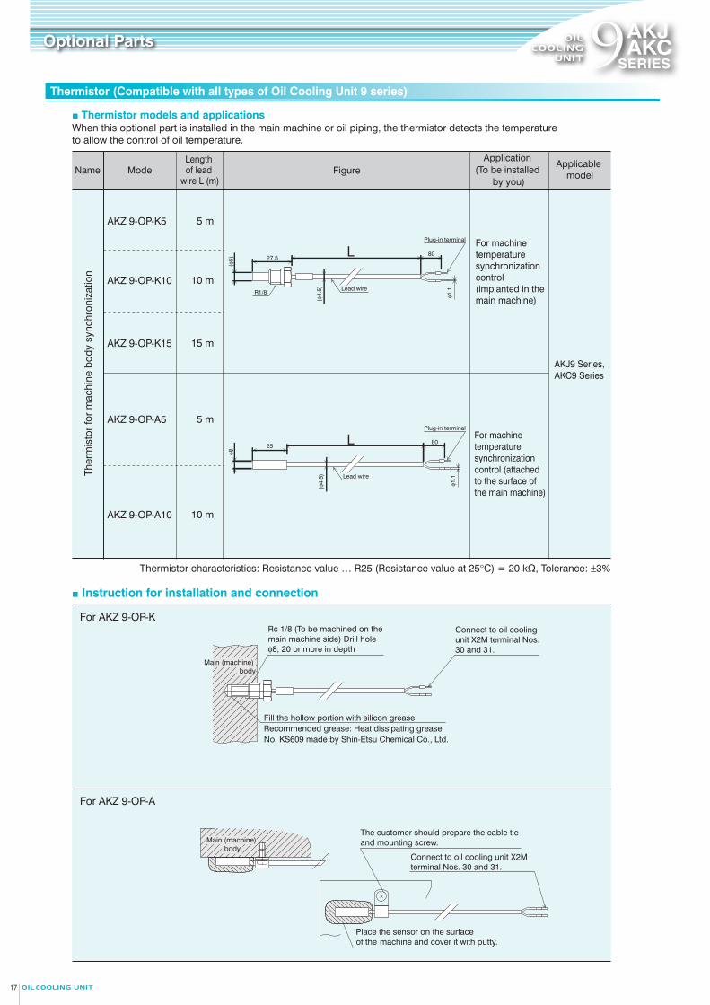
Optional Parts Optional Parts 9AKJAKC
SERIES9AKJAKC
SERIES
ModelNameLength of lead
wire L (m)
AKZ 9-OP-K5 5 m
AKZ 9-OP-A10 10 m
AKZ 9-OP-A5 5 m
AKZ 9-OP-K10 10 m
AKZ 9-OP-K15 15 m
Application (To be installed
by you)
Applicable model
AKJ9 Series, AKC9 Series
For machine temperature synchronization control (implanted in the main machine)
For machine temperature synchronization control (attached to the surface of the main machine)
Thermistor characteristics: Resistance value … R25 (Resistance value at 25°C) = 20 kΩ, Tolerance: ±3%
Figure
■ Instruction for installation and connection
■ Thermistor models and applications■ Installation positions of the thermistors for machine temperature synchronization.When this optional part is installed in the main machine or oil piping, the thermistor detects the temperature
to allow the control of oil temperature.
Place the sensor on the surface of the machine and cover it with putty.
The customer should prepare the cable tie and mounting screw.
Connect to oil cooling unit X2M terminal Nos. 30 and 31.
Main (machine) body
Rc 1/8 (To be machined on the main machine side) Drill hole φ8, 20 or more in depth
Fill the hollow portion with silicon grease. Recommended grease: Heat dissipating grease No. KS609 made by Shin-Etsu Chemical Co., Ltd.
Main (machine) body
For AKZ 9-OP-K
For AKZ 9-OP-A
27.580
(φ5)
(φ4.
5)R1/8Lead wire
Plug-in terminal
φ1.1
(φ4.
5) Lead wire
2580
φ8
Plug-in terminal
Ther
mis
tor
for
mac
hine
bod
y sy
nchr
oniz
atio
n
φ1.1
Note: 1. Refer to the specification sheet for the communication procedure and specifications.
■ Installation position for AKZ9-OP-CS (serial communication only)
Communication method
Serial communication only
Model
Installation plate inside control box
Installation position
PSP04664
Specification sheet No.
AKJ189, AKJ359, AKJ459, AKJ569, AKJ909, AKJ1509, AKC359, AKC569
Applicable model
• Dimensions of communication board (W × H): 40 × 50• The communication board is secured at four positions by locking support.
The following functions are enabled by mounting this option board on the Oil Cooling Unit and connecting it to the main machine:1. The operation mode and the operation setting can be changed from the main machine.
2. The alarm code and temperature data (machine temperature, room temperature, tank fluid
temperature, inverter frequency) of the Oil Cooling Unit can be read from the main machine.
AKZ9-OP-CS
Control board
D-SUB9 pin connector
Connect to CN14 on the control board
AKZ9-OP-CS board Supplied lead wire
Thermistor for machine synchronization
Installation position (No. 30 / 31 pin)
Thermistor (Compatible with all types of Oil Cooling Unit 9 series) Thermistor (Compatible with all types of Oil Cooling Unit 9 series)
Extension board for main machine communication
Connect to oil cooling unit X2M terminal Nos. 30 and 31.
AK
J9 /
AK
C9
SE
RIE
STh
erm
isto
r / E
xten
sion
boa
rd fo
r mai
n m
achi
ne c
omm
unic
atio
n
17 18
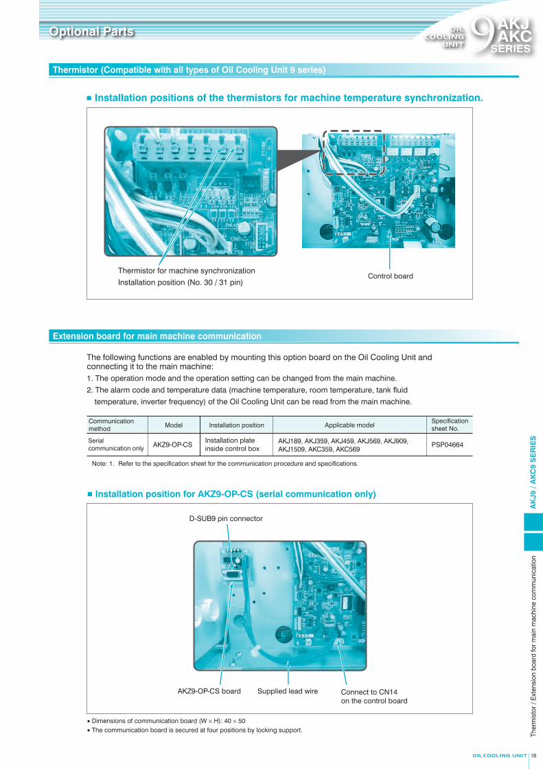
Optional Parts Optional Parts 9AKJAKC
SERIES9AKJAKC
SERIES
ModelNameLength of lead
wire L (m)
AKZ 9-OP-K5 5 m
AKZ 9-OP-A10 10 m
AKZ 9-OP-A5 5 m
AKZ 9-OP-K10 10 m
AKZ 9-OP-K15 15 m
Application (To be installed
by you)
Applicable model
AKJ9 Series, AKC9 Series
For machine temperature synchronization control (implanted in the main machine)
For machine temperature synchronization control (attached to the surface of the main machine)
Thermistor characteristics: Resistance value … R25 (Resistance value at 25°C) = 20 kΩ, Tolerance: ±3%
Figure
■ Instruction for installation and connection
■ Thermistor models and applications■ Installation positions of the thermistors for machine temperature synchronization.When this optional part is installed in the main machine or oil piping, the thermistor detects the temperature
to allow the control of oil temperature.
Place the sensor on the surface of the machine and cover it with putty.
The customer should prepare the cable tie and mounting screw.
Connect to oil cooling unit X2M terminal Nos. 30 and 31.
Main (machine) body
Rc 1/8 (To be machined on the main machine side) Drill hole φ8, 20 or more in depth
Fill the hollow portion with silicon grease. Recommended grease: Heat dissipating grease No. KS609 made by Shin-Etsu Chemical Co., Ltd.
Connect to Oil Cooling Unit X2M Terminal box Nos. 30 and 31.
Main (machine) body
For AKZ 9-OP-K
For AKZ 9-OP-A
27.580
(φ5)
(φ4.
5)R1/8Lead wire
Plug-in terminal
φ1.1
(φ4.
5) Lead wire
2580
φ8
Plug-in terminal
Ther
mis
tor
for
mac
hine
bod
y sy
nchr
oniz
atio
n
φ1.1
Note: 1. Refer to the specification sheet for the communication procedure and specifications.
■ Installation position for AKZ9-OP-CS (serial communication only)
Communication method
Serial communication only
Model
Installation plate inside control box
Installation position
PSP04664
Specification sheet No.
AKJ189, AKJ359, AKJ459, AKJ569, AKJ909, AKJ1509, AKC359, AKC569
Applicable model
• Dimensions of communication board (W × H): 40 × 50• The communication board is secured at four positions by locking support.
The following functions are enabled by mounting this option board on the Oil Cooling Unit and connecting it to the main machine:1. The operation mode and the operation setting can be changed from the main machine.
2. The alarm code and temperature data (machine temperature, room temperature, tank fluid
temperature, inverter frequency) of the Oil Cooling Unit can be read from the main machine.
AKZ9-OP-CS
Control board
D-SUB9 pin connector
Connect to CN14 on the control board
AKZ9-OP-CS board Supplied lead wire
Thermistor for machine synchronization
Installation position (No. 30 / 31 pin)
Thermistor (Compatible with all types of Oil Cooling Unit 9 series) Thermistor (Compatible with all types of Oil Cooling Unit 9 series)
Extension board for main machine communication
AK
J9 /
AK
C9
SE
RIE
STh
erm
isto
r / E
xten
sion
boa
rd fo
r mai
n m
achi
ne c
omm
unic
atio
n
17 18
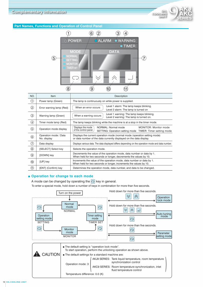
9AKJAKC
SERIES9AKJAKC
SERIES
■ Operation for change to each mode
Data display Displays various data. The data displayed differs depending on the operation mode and data number.7
Normal mode
Operation lock mode
Monitor mode
Auto tuning modeOperation
setting mode
Parameter setting mode
Timer setting mode
Hold down for more than five seconds.
Hold down for more than five seconds.
Hold down for more than five seconds.
Turn on the power
■ Setting procedureDefault setting: Set to operation mode 3, and a temperature of “0.0” °C
When you use your machine at a setting other than the default setting, change the setting following the procedure shown below.
Decreases the “MODE” number by 1.
The “setting temperature” is reduced by 0.1
Changing the Operation Mode Change the setting temperature
Press the [ENT] key to switch between
“MODE” and “DATA” .
To enter a special mode, hold down a number of keys in combination for more than five seconds.
3 Set the operation mode by pressing the or key.
5 Set the temperature by pressing the or key.
7 Return to the “NORMAL” mode by pressing the key three times.
NO. Item Description
A mode can be changed by operating the key in general.
1 Power ON Release the operation lock mode before starting operation for the first time. (Hold down the and keys together for at least 5 seconds.)
2 Select the “SETTING” operation setting mode (press the key once).
3 46
8 9 10 11
1 2
CAUTION
■ The default setting is “operation lock mode”.To start operation, perform the unlocking operation as shown above.
1 Power lamp (Green) The lamp is continuously on while power is supplied.
Timer mode lamp (Red) The lamp keeps blinking while the machine is at a stop in the timer mode.
8 [SELECT] Select key Selects the operation mode.
[DOWN] keyDecrements the value of the operation mode, data number or data by 1. When held for two seconds or longer, decrements the values by 10.9
[UP] key Increments the value of the operation mode, data number or data by 1. When held for two seconds or longer, increments the values by 10.
10
[ENT] (Confirm) key Determines the operation mode, data number, and data to be changed.11
Operation mode / Data No. display
Displays the current operation mode (normal mode /operation setting mode) or data number of the data currently displayed on the data display.6
Level 1 alarm: The lamp keeps blinking.Error warning lamp (Red) When an error occurs2
Warning lamp (Green)3Level 1 warning: The lamp keeps blinking.When a warning occurs
4
NORMAL: Normal mode MONITOR: Monitor modeOperation mode display
Displays the mode of the control panel.5
5
Blinking Blinking
*1. If the thermistor is not connected or has a broken wire, −99.9 is displayed.*2. With the default setting, 0 is displayed. Note that display is enabled when parameter n020 is “1” or the optional communication extension board is installed.*3. This is the roughly calculated value with a power supply voltage of 200 V (the error is approximately 20%).
7
NORMAL
TIMER SET
MONITOR
SETTING
Part Names, Functions and Operation of Control Panel Operation Mode and Setting Method
Checking Data in the Monitor Mode
Level 2 alarm: The lamp is turned on
Level 2 warning: The lamp is turned on.
SETTING: Operation setting mode TIMER: Timer setting mode
■ The default settings for a standard machine are:
Increases the “MODE” number by 1.
4 Confirm by pressing the key. 6 Confirm by pressing .
The “setting temperature” is increased by 0.1.
Complementary Information Complementary Information
Operation mode: 3 ( )Temperature difference: 0.0 (K)
AKJ9 SeriesOperation Mode No. Mode name Description Necessary optional partSetting temperature range
0 5 to 50°C
3 Room temperature −9.9 to +9.9 (K)
4 Machine temperature −9.9 to +9.9 (K)
AKC9 Series
Note: Refer to Page 17 for details of required optional parts.
Operation Mode No. Mode name Description Necessary optional partSetting temperature range
0 5 to 50°C
1 Maintains the outlet fluid at a fixed temperature 5 to 50°C
3 Room temperature −9.9 to +9.9 (K)
4 Machine temperature −9.9 to +9.9 (K)
5 Room temperature −9.9 to +9.9 (K)
6 Machine temperature −9.9 to +9.9 (K)
Tank fluid temperature, fixed temperature control
Inlet fluid temperature, fixed temperature control
Outlet fluid temperature, fixed temperature control
Inlet fluid temperature, room temperature synchronization control
Inlet fluid temperature / machine temperature synchronization control
Output fluid temperature / room temperature synchronization control
Outlet fluid temperature / machine temperature synchronization control
Maintains the tank fluid at a fixed temperature
Maintains the inlet fluid at a fixed temperature
Synchronizes the inlet fluid temperature with the room temperature
Synchronizes the inlet fluid temperature with the machine temperature
Synchronizes the outlet fluid temperature with the room temperature
Synchronizes the outlet fluid temperature with the machine temperature
Machine synchronization thermistor
Machine synchronization thermistor
Machine synchronization thermistor
Synchronizes the tank fluid temperature with the room temperature
Synchronizes the tank fluid temperature with the machine temperature
Tank fluid temperature, room temperature synchronization control
Tank fluid temperature / machine temperature synchronization control
The following data can be checked in the monitor mode.
Monitor No.Description
AKJ9 AKC9Note
0 Machine body temperature [Th1] *1
1 − Outlet fluid temperature [Th2]
∆T [Th4 - Th2]
Inlet fluid temperature [Th4]
Intake gas temperature [Th5]
*1
2 Room temperature [Th3] *1
3 Tank fluid temperature [Th4] *1
4 *1
5 − *1
6 Cooling capacity control command value (%) −7 Compressor inverter rotational speed (rps) −8 Power consumption (kW) *3
9 Extended DIN (hundreds digit), DOUT (tens digit) status *2
Monitor No.Description
NoteAKJ9 AKC9
AK
J9 /
AK
C9
SE
RIE
SC
ontro
l Pan
el /
Ope
ratio
n M
ode/
Setti
ng M
etho
d
AKJ9 SERIES:
AKC9 SERIES:
Tank liquid temperature, room temperature synchronization control
Room temperature synchronization, inlet fluid temperature control
2019
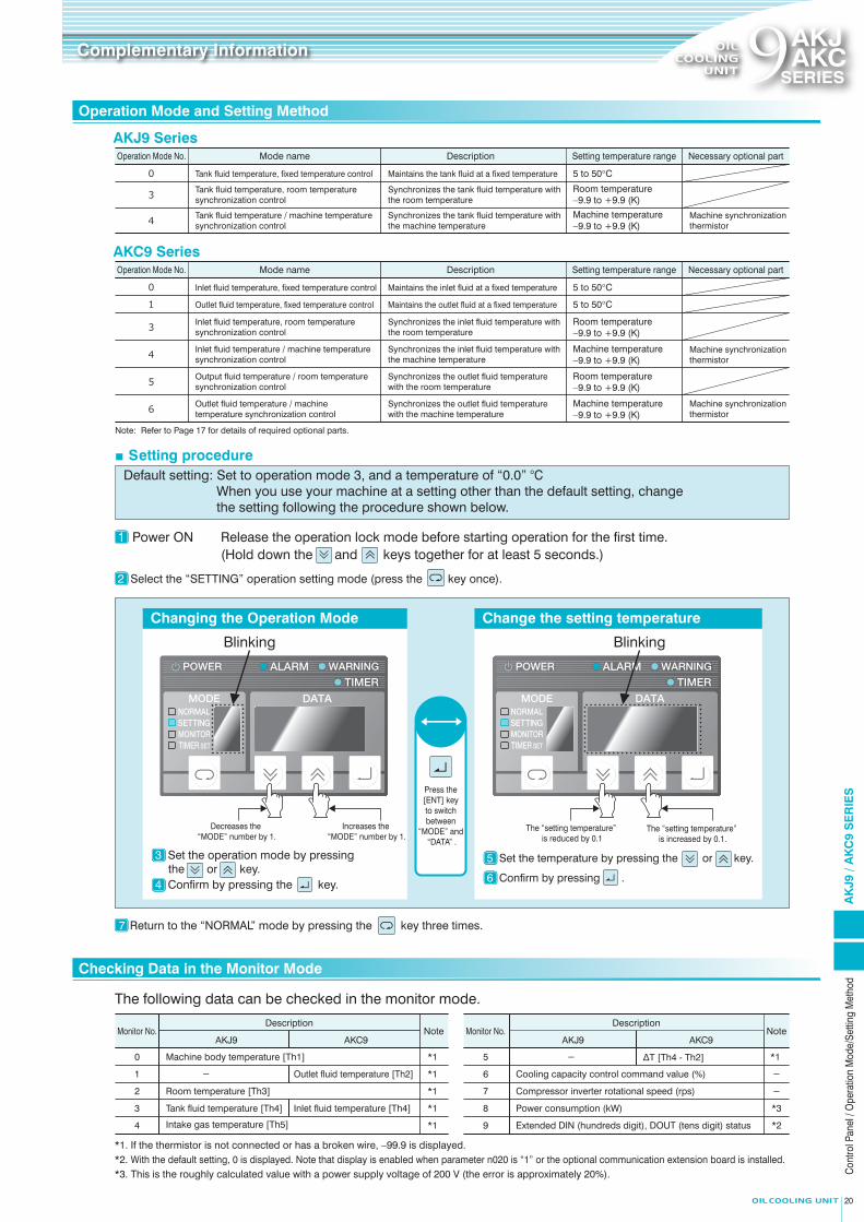
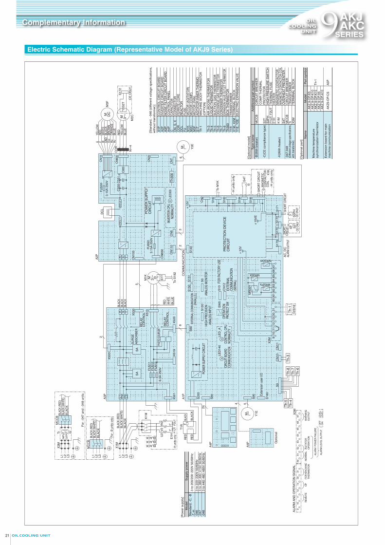
9AKJAKC
SERIES9AKJAKC
SERIES
Electric Schematic Diagram (Representative Model of AKJ9 Series) Electric Schematic Diagram (Representative Model of AKC9 Series)
Complementary Information Complementary Information
CO
MM
UN
ICA
TIO
N
[Opt
iona
l par
t]
Add
ition
al p
art s
ymbo
lTy
pe n
ame
Par
t sym
bol
Mod
elN
ame
Ext
ensi
on b
oard
for m
ain
mac
hine
com
mun
icat
ion
AK
Z9-O
P-C
S
Th-1
AK
Z 9-
OP-
A10
AK
Z 9-
OP-
A5
AK
Z 9-
OP-
K10
A5P
AK
Z 9-
OP-
K5
Mac
hine
tem
pera
ture
syn
chro
niza
tion
ther
mis
tor
S4T
E1H
OV
ER
HE
AT
PR
EV
EN
TER
HE
ATE
RK
2MM
AG
NE
TIC
CO
NTA
CTO
R
MIP
MO
TOR
(P
UM
P)
-H -200
(U
nit w
ith p
ump)
-C
(With
hea
ter)
(CE
com
plia
nce
type
)
[Opt
iona
l mod
el]
[Sta
ndar
d]
CO
R
T1R S
3PH
OFF
ON
PU
MP
OP
ER
ATI
ON
6766
6564
6362
6160
X2M
931
3013
1211
10
CO
NTR
OL
PAN
EL
A4P
TRA
NS
FOR
ME
R
ELE
CTR
IC E
XPA
NS
ION
VA
LVE
Y1E
, Y2E
TER
MIN
AL
BLO
CK
X1M
, X2M
BO
X T
HE
RM
ISTO
RTh
300
DIS
CH
ARG
E G
AS T
HER
MIS
TOR
Th-6
CO
ND
ENSE
R T
HER
MIS
TOR
Th-7
EXPA
NSIO
N VA
LVE
OUT
LET
THER
MIS
TOR
Th-8
OP
TIO
N L
IQU
ID T
HE
RM
ISTO
RTh
-9
MA
CH
INE
BO
DY
TH
ER
MIS
TOR
(O
PTI
ON
)Th
-1LI
QU
ID O
UTL
ET
THE
RM
ISTO
RTh
-2
LIQ
UID
TH
ER
MIS
TOR
Th-4
SU
CTI
ON
GA
S T
HE
RM
ISTO
RTh
-5
AIR
(R
OO
M)
THE
RM
ISTO
RTh
-3
FER
RIT
E C
OR
ER
EA
CTO
RD
CL
M2C
MO
TOR
(C
OM
P.)
M3F
MO
TOR
(FA
N)
HIG
H P
RE
SS
UR
E S
WIT
CH
CO
MP.
TH
ER
MA
L P
RO
TEC
TOR
S2T
CO
NN
EC
TOR
CN
, S, X
CIR
CU
IT B
RE
AK
ER
MC
CB
FUFU
SE
K1S
OV
ER
CU
RR
EN
T R
ELA
Y
NO
ISE
FIL
TER
CIR
CU
IT B
OA
RD
A3P
CC
APA
CIT
OR
INV
ER
TER
CIR
CU
IT B
OA
RD
A2P
A1P
CO
NTR
OL
CIR
CU
IT B
OA
RD
MAG
NET
IC C
ON
TAC
TOR
CO
IL
F1U
T, F
2UT
THE
RM
AL
FUS
E
4 5
[Pow
er s
uppl
y]
3 to
200
/200・2
20V
50/
60H
zS
tand
ard,
-C, -
H-2
00
Mod
elS
uppl
y po
wer
AK
Z 9-
OP-
K15
S10 CN
12S
W0
A5P
A4P O
ptio
nal
BLA
CK
BLA
CK
BLA
CK
Bla
ckBL
ACK
(WH
ITE)
BLAC
K (R
ED)
A3P
A2P
R S T
2
L2 L3L1
Pow
er s
uppl
y3
to 2
00/2
00・2
20V
50/
60H
z
MC
CB
X50
0
X50
1
SU
RG
E
ABS
OR
BE
RX
530
SA
SA
5
6
L3L2L1
RED
RED
BLAC
K
BLAC
KT1
R t°
t°t°
W2
K2M
V2
U2BLACK
BLACKBLACK
E1H
F1U
TF2
UT
6.3A
250
V
X51
0
X52
0X
519
FU51
3FU
512
FU51
1M
1PK
1S
3~M
BLA
CK
BLA
CK
(W
HIT
E)
BLA
CK
(R
ED
)
L3L2L1
T3T2T1U
1V
1W
1
CN
103
CN
650
CN
6C
N11
0
FU65
03.
15A
250
V
R S T
LED3
00
32
-
~-+
Th30
0
Y2E
CN
7
CN
20
CN
18
M6
S2T
ΘS
172
M2C3~M
N=
4
CO
RH
vH
uV
ccG
ND
WVU
M3F
DCM
CN
15
CN
600
DC
L
IC60
0-+
- ~
+ -
C55
1C
550
-+
3.15
A 2
50V
FU55
0
DC
L2
DC
L1
~
-
S14
0+
12V
CN
2
S18
2
K1S
S18
39596
S18
4
S18
5
AC
, DC
S2T
ΘS
3PH
S17
2S
171
S17
0S
179
+12
V
+15
VE
MAG
NETI
C CO
NTAC
TOR
COIL
K2M
S4T
Opt
iona
l
Opt
iona
l
Th-1
Th-6
Th-7
Th-8
X2M
3130
1312
1110
967
6665
6463
6261
Th-3
Th-2
Th-9
Th-5
Th-4
CN
11C
N10
S9
60
MR52Pa
MR
30Y
MR30X
MR30W
S16
0
S90
Exte
nsio
n us
er I/
O
S15
1S
150
LED
_ALE
D14
0
S60
S13
0S
0
-
~
S80
S20
024
A1P
Y1EM
RE
LAY
C
ON
TRO
L
PHOT
O CO
UPLE
R
POW
ER S
UPP
LY C
IRC
UIT
EXTE
RNAL
COM
MUNI
CATIO
N(P
ARAL
LEL)
HIGH
PRE
CISI
ON
ANAL
OG IN
PUT
ANAL
OG M
ONIT
OR
CIRC
UIT B
OARD
CO
MMUN
ICAT
ION
CONT
ROL
CPU
NORM
ALIT
Y
FOR
FACT
ORY
USE
OPER
ATIO
N PR
OTEC
T SW
PR
OTE
CTI
ON
DE
VIC
E
CIR
CU
ITEX
TERN
AL
COM
MUN
ICAT
ION
(SER
IAL)
LEV
EL
1LE
VE
L 2
WA
RN
ING
O
UTP
UT
ALA
RM
LE
VE
L O
UTP
UT
ALA
RM・P
OW
ER
FA
ILU
RE
NO
RM
AL
ALA
RM
AN
D O
PE
RA
TIO
N S
IGN
AL
FOR
MA
CH
INE
TH
ER
MIS
TOR
OP
RE
MO
TE
CE O
NLY
CE O
NLY
SHO
RT
CIRC
UIT
SHO
RT C
IRCU
ITAL
ARM
OUT
PUT
SHO
RT C
IRCU
IT
PO
WE
R S
UP
PLY
C
IRC
UIT
INVE
RTER
CPU
NO
RMAL
ITY
BLU
EO
RAN
GE
BRO
WN
BLAC
KW
HIT
ERE
DYE
LLO
W
RED
YELL
OW
BLU
E
CE
ON
LY
A5P
[Opt
iona
l par
t]
Add
ition
al p
art s
ymbo
lTy
pe n
ame
Par
t sym
bol
Mod
elN
ame
Ext
ensi
on b
oard
for
mai
n m
achi
ne c
omm
unic
atio
nA
KZ9
-OP-
CS
Th-1
AK
Z 9-
OP-
A10
AK
Z 9-
OP-
A5
AK
Z 9-
OP-
K10
A5P
AK
Z 9-
OP-
K5
Mac
hine
tem
pera
ture
sy
nchr
oniz
atio
n th
erm
isto
r
Opt
iona
lTh
-1
S4T
E1H
−H u
nits
onl
y
S4T
RED
RED
BLA
CK
BLAC
KT1
R t°
For –
B un
its o
nly
BLA
CK
BLAC
K (W
HITE
)BL
ACK
(RED
)M
CC
B
L2 L3L1
OV
ER
HE
AT
PR
EV
EN
TER
HE
ATE
RK
1MM
AG
NE
TIC
CO
NTA
CTO
R
MC
CB
CIR
CU
IT B
RE
AK
ER
CIR
CU
IT B
RE
AK
ER
MC
CB
-H -047
,048
-C-B
(With
hea
ter)
(Diffe
rent
volta
ge sp
ecific
atio
ns,
with
tran
sform
er)
(CE
com
plia
nce
type
)
(With
bre
aker
)
[Opt
iona
l mod
el]
[Sta
ndar
d, −
046
(diff
eren
t vol
tage
spe
cific
atio
ns,
with
out t
rans
form
er)]
BLU
EW
HITE
RED
CO
R
LEV
EL
1LE
VE
L 2
OFF
ON
WA
RN
ING
O
UTP
UT
ALA
RM
LE
VE
L O
UTP
UT
ALA
RM・P
OW
ER
FA
ILU
RE
AG
ITA
TOR
O
PE
RA
TIO
NN
OR
MA
L
6766
6564
6362
6160
Th-6
Th-7
Th-8
S9
T1R
S3P
H
EXTE
RNAL
COM
MUNI
CATIO
N(P
ARAL
LEL)
S15
1S
150
CE
ON
LY
S2T
CE O
NLY
CE O
NLY
SHO
RT
CIRC
UIT
SHO
RT C
IRCU
IT
BLAC
KBL
ACK
BLAC
K
BLA
CK
BLAC
K (W
HITE
)BL
ACK
(RED
)BL
UE
ORA
NG
EBR
OW
NBL
ACK
WH
ITE
RED
YELL
OW
HvHuVcc
GND
WVU
Θ
Θ
S17
2
X2M
9
ALA
RM
AN
D O
PE
RA
TIO
N S
IGN
AL
FOR
MA
CH
INE
TH
ER
MIS
TOR
OP
RE
MO
TE
3130
1312
1110
CO
NTR
OL
PAN
EL
A4P
TRA
NS
FOR
ME
R
ELE
CTR
IC E
XPA
NS
ION
VA
LVE
Y1E
, Y2E
TER
MIN
AL
BLO
CK
X1M
, X2M
BO
X T
HE
RM
ISTO
RTh
300
DIS
CH
ARG
E G
AS T
HER
MIS
TOR
Th-6
CO
ND
ENSE
R T
HER
MIS
TOR
Th-7
EXPA
NSIO
N VA
LVE
OUT
LET
THER
MIS
TOR
Th-8
AG
ITA
TOR
INN
ER
TH
ER
MO
S1T
MA
CH
INE
BO
DY
TH
ER
MIS
TOR
(O
PTI
ON
)Th
-1
LIQ
UID
TH
ER
MIS
TOR
Th-4
SU
CTI
ON
GA
S T
HE
RM
ISTO
RTh
-5
AIR
(R
OO
M)
THE
RM
ISTO
RTh
-3
FER
RIT
E C
OR
ER
EA
CTO
RD
CL
DC
L
6.3A
250
V
SU
RG
E
AB
SO
RB
ER
PHOT
O CO
UPLE
R
LED3
00IN
VERT
ER C
PU
NORM
ALIT
Y
CN
103
- ~
X2M
A4P
A3P
A2P
A1P
CO
MM
UN
ICA
TIO
N
- ~-+
Th30
0
Y1E
Y2E
M2C
M3F
M
IC60
0-+
- ~
CN
650
X50
0
RE
LAY
C
ON
TRO
L
RE
LAY
C
ON
TRO
L
M1K
S1T
DCM
3~M
PR
OTE
CTI
ON
DE
VIC
E
CIR
CU
IT
S16
0
S90
LED
_ALE
D14
0
CIRC
UIT B
OARD
CO
MMUN
ICAT
ION
CONT
ROL
CPU
NORM
ALIT
Y
M2C
MO
TOR
(C
OM
P.)
M3F
MO
TOR
(FA
N)
HIG
H P
RE
SS
UR
E S
WIT
CH
CO
MP.
TH
ER
MA
L P
RO
TEC
TOR
S2T
CO
NN
EC
TOR
CN
, S, X
MO
TOR
(A
GIT
ATO
R)
M1K
FUFU
SE
NO
ISE
FIL
TER
CIR
CU
IT B
OA
RD
A3P
CC
APA
CIT
OR
INV
ER
TER
CIR
CU
IT B
OA
RD
A2P
ALAR
M O
UTPU
TA
C, D
C
S2T
ΘS
3PH
S17
2S
171
S17
0S
179
A1P
CO
NTR
OL
CIR
CU
IT B
OA
RD
S60
POW
ER S
UPPL
Y CI
RCUI
T
+12
V
S14
0+
12V
+15
VE
CN
2
S183
S184
S182
S185
3130
1312
1110
967
6665
6463
6261
Th-3
Th-5
Th-4
CN
11C
N10
S80
S20
0
RED
YELL
OW
BLU
E
CN
7C
N6
CN
110
CN
20
+ -
C55
1C
550
PO
WE
R S
UP
PLY
C
IRC
UIT
CN
15
-+
3.15
A 2
50V
FU55
0
DC
L2
DC
L1
FU65
03.
15A
250
V
60
X53
0
X51
0
X52
0X
519
X50
1
FU51
3FU
512
FU51
1
SA
SA
L3L2L1
N=
4
X1M
Opt
iona
l
Exte
nsio
n us
er I/
O
HIGH
PRE
CISI
ON
ANAL
OG IN
PUT
S13
0
CN
600
R S T
R S T
W2
V2
U2
BLACKBLACKBLACK
−H u
nits
onl
yE
1HF1
UT
F2U
T
MAG
NET
IC
CO
NTA
CTO
R C
OIL
K1M
−H u
nits
onl
y
t°t°
M
5
63
26
5
2
MAG
NET
IC C
ON
TAC
TOR
CO
IL
F1U
T, F
2UT
THE
RM
AL
FUS
E
24
4
X3M
TER
MIN
AL
BLO
CK
L2 L3L1
TrTR
AN
SFO
RM
ER
~-
[Pow
er s
uppl
y]
3 to
200
/200・2
20V
50/
60H
zS
tand
ard,
-C, -
B-T
,-H-0
46-0
47-0
48
3 to
220・2
30V
50/
60H
z3
to 3
80・4
00・4
15V
50/
60H
z3
to 4
40・4
60・4
80V
50/
60H
z
Mod
elS
uppl
y po
wer
MR52Pa
MR
30Y
MR30X
MR30W
AK
Z 9-
OP-
K15
CO
R
X3M
L2 L3L1Tr
INP
UT
OUT
PUT 0V
MC
CB
For
−047
and
−04
8 un
its
BLA
CK
BLAC
K (W
HITE
)BL
ACK
(RED
)
SHO
RT C
IRC
UIT
CN
12
S10
FOR
FACT
ORY
USE
OPER
ATIO
N PR
OTEC
T SW
S0
EXTE
RNAL
CO
MM
UNIC
ATIO
N (S
ERIA
L)
SW
0
K1M
3~M Θ
To S
182
To M
1K
ANAL
OG M
ONIT
OR
-H ty
pe o
nly
-H ty
pe o
nly
-200
type
onl
y
RE
LAY
C
ON
TRO
L
AK
J9 /
AK
C9
SE
RIE
SE
lect
ric S
chem
atic
Dia
gram
2221
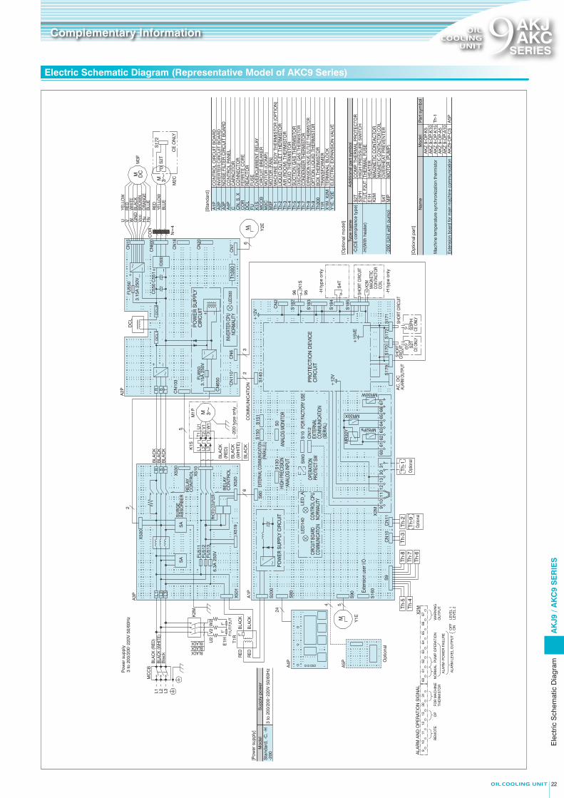

AWG#14 or more
2.5 mm2 or more
M4 2.0 mm2 or moreM5
X1M
Breaker
Normal
Level 1 error or Lock
(2) Warning output chartWarning statusNon-warning status
OFFON66 - 67
Signal output
Operation status
(1) Alarm/operation status output chartRemote operation (between [10] and [11])
OFFON
Level 2 errorPower failure (Power OFF)NormalLevel 2 error
Power failure (Power OFF)Normal
Level 1 error or Lock
Level 1 error or Lock
Level 2 error Power failure (Power OFF)
Level 2 error Power failure (Power OFF)
Level 1 error or Lock
OFFONOFFONOFFONOFFON
61 - 62
60 - 64
60 - 63
60 - 61
Agitator operation (NO contact)
Warning output (NO contact)
Error level (“a” contact)
Error / Stop (Power OFF) (“b” contact)
Normal (“a” contact)
Signal output
Operation status
1. The following electric wires can be used on the terminal block for straight crimp-style terminals. Single wire: φ0.57 to φ1.44 (AWG#22~#16) Stranded wire: 0.25 mm2 to 1.25 mm2 (AWG#22~16)
2. Load applicable to [60 - 64] and [66 - 67] is as follows: Min. applicable load: 10mV DC, 10 µA or more Max. applicable load: 30 V DC, 2 A (Resistance load)
3. For [10] to [13], please prepare contacts to meet the condition of minimum applicable load 12 V DC and 5 mA.
4. When the length of the thermistor to be connected to [30] - [31] is longer than 10m, or the wiring is routed in a poor noise environment, use shielded wire.
CAUTION
4 Signal output time chart
(1) AKJ9: With the standard and optional (-C, -H, -046) types: • Connect to X1M.
(2) AKJ9: With the “with breaker” (-B) specifications: AKC9: All models: • Connect to the breaker.
(3) AKJ9: With different voltage types (with transformer: -047, -048): • Connect to the terminal block supplied with the transformer.
1. Always install an all-pole (3-pole) circuit breaker* (to be prepared by the customer) of the specified capacity on the main power supply.* All contact distances must be at least 3 mm.
2. Always ground the machine. Since a noise filter is installed, there is a risk of electrical shock without proper grounding.
3. Before opening the electric component box, always turn off the power, and wait for 5 minutes until internal high voltage has been discharged.
4. Do not energize the equipment with the electric component box kept open.
DANGER
1. To avoid the effects of noise, connect the power wire by cutting it to the proper length so that no excess wire comes into contact with the control board or others.
2. To perform remote control, remove the short-circuit wire between [10] and [11] and install an operation switch (to be prepared by the customer).
3. The mode is set to “Lock mode (Stop mode)” by default. Before starting operation, follow the procedure to release the Lock mode from the operation panel. Refer to the operation manual for the unlocking procedure.
4. The unit is provided with a misoperation prevention switch (PROTECT) to reject setting from the operation panel. If you want to use this function, make the necessary setting referring to the operation manual.
CAUTION
1
2
3 Connection to signal terminal block (X2M)
1. Screw terminal and wiring diameter
2. Use a round crimp-style terminal for connection.3. The terminal block is for three poles and the ground wire is to be
secured on the enclosure with a screw.
Wiring diameter
AWG#12 or more
UL cable
4.0 mm2 or more
IEC cable
M5 3.5 mm2 or more
JIS cableScrew terminalSeries
1. Straight crimp terminal and wiring diameter
2. Use a straight crimp-style terminal for connection.3. Use stranded wires for electric connection.4. The wiring size is 0.5 mm2 to 1.5 mm2 in the case of duplex cable according
to IEC. If using stripped wires, make the stripped length 9 to 10 mm. * Recommended models and manufacturers: TGN TC-1.25-9T (NICHIFU Co., Ltd.)
APA-1.25N (Daido Solderless Terminal)
(1) (2)L1 L3L2
L1 L3L2
(3)
-048-047
Connect the lines to the terminals corresponding to the main power supply.
415480
415480
415480440V 460 440 460 440 460
380V 400 380 400 380 400
W X3MVUM
R52
Pa
MR
30X
MR
30W
Unassigned (Do not connect to this terminal)
Interior of oil cooling unit
(X2M)
Unassigned (Do not connect to this terminal)
Warning output
Remote controlFor connection
of machine synchronization
thermistor
For connection of optional protection
equipment (OP)
63 64 65 66 679 10 11 12 13 30 31 60 61 62
Normal Agitator operation/pump operation
Error / Power failure
Alarm level output (OFF: Level 1, ON: Level 2)
MR30Y
M5
X1M
Terminal block
BreakerAKJ 909,1509
Wiring diameter
AWG#22 to #16
UL cable
0.3 mm2 to 1.5 mm2
IEC cable
0.25 mm2 to 1.25 mm2
JIS cableStraight pin terminals
*
Normal
1. When rough transport conditions are expected while transporting the machine overseas or elsewhere, special precautions should be taken in the packaging and transportation method so as to avoid the application of excessive force on the oil cooling unit (this unit).
2. Oil Cooling Unit (this machine) does not incorporate a flow switch for checking the oil supply and a temperature switch for abnormal supply of oil temperature (high temperature or low temperature). So, please provide a protection device such as a flow.
1. Do not use the oil cooling unit to cool a fluid from 50°C or higher. Start to operate the oil cooling unit at the same time as the main machine or before the fluid temperature rises to 40°C.
2. Do not place an object that hinders ventilation within 500 mm of the air-intake or exhaust.
3. If the air filter is clogged, the cooling capacity is reduced. Clean the air filter (wash with hot water or clean with air) periodically once every two weeks to prevent clogging.
4. If cutting chips and powder-like chips deposit on and adhere to the cooling coil (evaporator) in the AKJ9 series, the cooling capacity should be diminished and it could cause failure. To avoid the adherence of deposits on the cooling coil, install an efficient return filter on the return side (fluid inlet) of the tank and periodically clean the tank inside.
1. The fluid usable with the oil cooling unit is listed in the table below for each series. ( symbol … Can be used, “Unusable” symbol … Cannot be used)
2. Do not use fluid listed below as “unusable”
Description AKJ 9 Series
Lubrication oil
Mineral hydraulic oil
Nonflammable hydraulic oil• Phosphate ester hydraulic fluid• Chlorinated hydrocarbon series• Water - Glycol series• W/O - O/W emulsion series
(High-aqueous hydraulic oil)
Unusable
Coolant fluid• Water-soluble cutting and grinding fluid• Non water-soluble cutting and grinding oil
Water (Industrial water)
Drugs Unusable
Inflammable liquid like fuel Unusable
Liquid equivalent to special flammables, alcohol, first class petroleum and second class petroleum of the fourth group hazardous materials specified according to the Fire Defense Law
Liquid for food products UnusableDrinking water, water for cooling food products, etc.
● Important notes to be observed regarding the main machine side (machine tools and industrial machinery)
Ethylene glycol (Antifreeze liquid)
AKC 9 Series
Unusable
Unusable
Unusable
Unusable
Unusable
UnusableFluid not including any ingredient that corrodes the SUS304 material used for the evaporator coil
• Oil that is classified as third class petroleum or fourth class petroleum of the fourth group hazardous materials stipulated in the Fire Defense Law and that corresponds to discoloration No. 1 in the copper corrosion test method (JIS K2513) of petroleum products
9AKJAKC
SERIES9AKJAKC
SERIES
Electric Wiring Connection Instruction Diagram Notes for Handling
Notes for operation and cooling capacity
Notes regarding fluid usable with Oil Cooling Unit
Complementary Information Complementary Information
Connection to power supply terminal block (X1M, Tr)
Power supply capacity … Power supply capacity … Refer to the maximum power consumption/maximum current consumption panel of the specifications list (Pages 5, 6 and 14).
Elec
tric
Wiri
ng C
onne
ctio
n In
stru
ctio
n D
iagr
am /
Not
es fo
r ha
ndlin
g
AKJ 189, 359, 459, 569AKC 359, 569
AK
J9 /
AK
C9
SE
RIE
S
2423
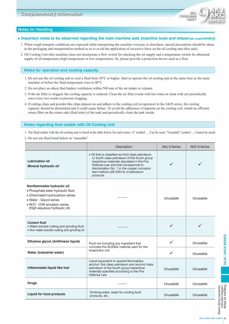
AWG#14 or more
2.5 mm2 or more
M4 2.0 mm2 or moreM5
X1M
Breaker
Normal
Level 1 error or Lock
(2) Warning output chartWarning statusNon-warning status
OFFON66 - 67
Signal output
Operation status
(1) Alarm/operation status output chartRemote operation (between [10] and [11])
OFFON
Level 2 errorPower failure (Power OFF)NormalLevel 2 error
Power failure (Power OFF)Normal
Level 1 error or Lock
Level 1 error or Lock
Level 2 error Power failure (Power OFF)
Level 2 error Power failure (Power OFF)
Level 1 error or Lock
OFFONOFFONOFFONOFFON
61 - 62
60 - 64
60 - 63
60 - 61
Agitator operation (NO contact)
Warning output (NO contact)
Error level (“a” contact)
Error / Stop (Power OFF) (“b” contact)
Normal (“a” contact)
Signal output
Operation status
1. The following electric wires can be used on the terminal block for straight crimp-style terminals. Single wire: φ0.57 to φ1.44 (AWG#22~#16) Stranded wire: 0.25 mm2 to 1.25 mm2 (AWG#22~16)
2. Load applicable to [60 - 64] and [66 - 67] is as follows: Min. applicable load: 10mV DC, 10 µA or more Max. applicable load: 30 V DC, 2 A (Resistance load)
3. For [10] to [13], please prepare contacts to meet the condition of minimum applicable load 12 V DC and 5 mA.
4. When the length of the thermistor to be connected to [30] - [31] is longer than 10m, or the wiring is routed in a poor noise environment, use shielded wire.
CAUTION
4 Signal output time chart
(1) AKJ9: With the standard and optional (-C, -H, -046) types: • Connect to X1M.
(2) AKJ9: With the “with breaker” (-B) specifications: AKC9: All models: • Connect to the breaker.
(3) AKJ9: With different voltage types (with transformer: -047, -048): • Connect to the terminal block supplied with the transformer.
1. Always install an all-pole (3-pole) circuit breaker* (to be prepared by the customer) of the specified capacity on the main power supply.* All contact distances must be at least 3 mm.
2. Always ground the machine. Since a noise filter is installed, there is a risk of electrical shock without proper grounding.
3. Before opening the electric component box, always turn off the power, and wait for 5 minutes until internal high voltage has been discharged.
4. Do not energize the equipment with the electric component box kept open.
DANGER
1. To avoid the effects of noise, connect the power wire by cutting it to the proper length so that no excess wire comes into contact with the control board or others.
2. To perform remote control, remove the short-circuit wire between [10] and [11] and install an operation switch (to be prepared by the customer).
3. The mode is set to “Lock mode (Stop mode)” by default. Before starting operation, follow the procedure to release the Lock mode from the operation panel. Refer to the operation manual for the unlocking procedure.
4. The unit is provided with a misoperation prevention switch (PROTECT) to reject setting from the operation panel. If you want to use this function, make the necessary setting referring to the operation manual.
CAUTION
1
2
3 Connection to signal terminal block (X2M)
1. Screw terminal and wiring diameter
2. Use a round crimp-style terminal for connection.3. The terminal block is for three poles and the ground wire is to be
secured on the enclosure with a screw.
Wiring diameter
AWG#12 or more
UL cable
4.0 mm2 or more
IEC cable
M5 3.5 mm2 or more
JIS cableScrew terminalSeries
1. Straight crimp terminal and wiring diameter
2. Use a straight crimp-style terminal for connection.3. Use stranded wires for electric connection.4. The wiring size is 0.5 mm2 to 1.5 mm2 in the case of duplex cable according
to IEC. If using stripped wires, make the stripped length 9 to 10 mm. * Recommended models and manufacturers: TGN TC-1.25-9T (NICHIFU Co., Ltd.)
APA-1.25N (Daido Solderless Terminal)
(1) (2)L1 L3L2
L1 L3L2
(3)
-048-047
Connect the lines to the terminals corresponding to the main power supply.
415480
415480
415480440V 460 440 460 440 460
380V 400 380 400 380 400
W X3MVU
MR
52P
a
MR
30X
MR
30W
Unassigned (Do not connect to this terminal)
Interior of oil cooling unit
(X2M)
Unassigned (Do not connect to this terminal)
Warning output
Remote controlFor connection
of machine synchronization
thermistor
For connection of optional protection
equipment (OP)
63 64 65 66 679 10 11 12 13 30 31 60 61 62
Normal Agitator operation/pump operation
Error / Power failure
Alarm level output (OFF: Level 1, ON: Level 2)
MR30Y
M5
X1M
Terminal block
BreakerAKJ 909,1509
Wiring diameter
AWG#22 to #16
UL cable
0.3 mm2 to 1.5 mm2
IEC cable
0.25 mm2 to 1.25 mm2
JIS cableStraight pin terminals
*
Normal
1. When rough transport conditions are expected while transporting the machine overseas or elsewhere, special precautions should be taken in the packaging and transportation method so as to avoid the application of excessive force on the oil cooling unit (this unit).
2. Oil Cooling Unit (this machine) does not incorporate a flow switch for checking the oil supply and a temperature switch for abnormal supply of oil temperature (high temperature or low temperature). So, please provide a protection device such as a flow.
1. Do not use the oil cooling unit to cool a fluid from 50°C or higher. Start to operate the oil cooling unit at the same time as the main machine or before the fluid temperature rises to 40°C.
2. Do not place an object that hinders ventilation within 500 mm of the air-intake or exhaust.
3. If the air filter is clogged, the cooling capacity is reduced. Clean the air filter (wash with hot water or clean with air) periodically once every two weeks to prevent clogging.
4. If cutting chips and powder-like chips deposit on and adhere to the cooling coil (evaporator) in the AKJ9 series, the cooling capacity should be diminished and it could cause failure. To avoid the adherence of deposits on the cooling coil, install an efficient return filter on the return side (fluid inlet) of the tank and periodically clean the tank inside.
1. The fluid usable with the oil cooling unit is listed in the table below for each series. ( symbol … Can be used, “Unusable” symbol … Cannot be used)
2. Do not use fluid listed below as “unusable”
Description AKJ 9 Series
Lubrication oil
Mineral hydraulic oil
Nonflammable hydraulic oil• Phosphate ester hydraulic fluid• Chlorinated hydrocarbon series• Water - Glycol series• W/O - O/W emulsion series
(High-aqueous hydraulic oil)
Unusable
Coolant fluid• Water-soluble cutting and grinding fluid• Non water-soluble cutting and grinding oil
Water (Industrial water)
Drugs Unusable
Inflammable liquid like fuel Unusable
Liquid equivalent to special flammables, alcohol, first class petroleum and second class petroleum of the fourth group hazardous materials specified according to the Fire Defense Law
Liquid for food products UnusableDrinking water, water for cooling food products, etc.
● Important notes to be observed regarding the main machine side (machine tools and industrial machinery)
Ethylene glycol (Antifreeze liquid)
AKC 9 Series
Unusable
Unusable
Unusable
Unusable
Unusable
UnusableFluid not including any ingredient that corrodes the SUS304 material used for the evaporator coil
• Oil that is classified as third class petroleum or fourth class petroleum of the fourth group hazardous materials stipulated in the Fire Defense Law and that corresponds to discoloration No. 1 in the copper corrosion test method (JIS K2513) of petroleum products
9AKJAKC
SERIES9AKJAKC
SERIES
Electric Wiring Connection Instruction Diagram Notes for Handling
Notes for operation and cooling capacity
Notes regarding fluid usable with Oil Cooling Unit
Complementary Information Complementary Information
Connection to power supply terminal block (X1M, Tr)
Power supply capacity … Power supply capacity … Refer to the maximum power consumption/maximum current consumption panel of the specifications list (Pages 5, 6 and 14).
Elec
tric
Wiri
ng C
onne
ctio
n In
stru
ctio
n D
iagr
am /
Not
es fo
r ha
ndlin
g
AKJ 189, 359, 459, 569AKC 359, 569
AK
J9 /
AK
C9
SE
RIE
S
2423
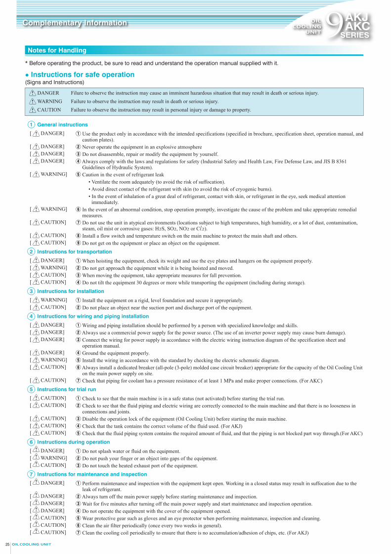
1 General instructions
[ DANGER]
[ DANGER][ DANGER][ DANGER]
[ WARNING]
[ WARNING]
[ CAUTION]
[ CAUTION][ CAUTION]
2 Instructions for transportation
[ DANGER][ WARNING][ CAUTION][ CAUTION]
3 Instructions for installation
[ WARNING][ CAUTION]
4 Instructions for wiring and piping installation
[ DANGER][ DANGER][ DANGER]
[ DANGER][ WARNING][ CAUTION]
[ CAUTION]
5 Instructions for trial run
[ CAUTION][ CAUTION]
[ CAUTION][ CAUTION][ CAUTION]
6 Instructions during operation
[ DANGER][ WARNING][ CAUTION]
7 Instructions for maintenance and inspection
[ DANGER]
[ DANGER][ DANGER][ DANGER][ CAUTION] [ CAUTION] [ CAUTION]
DANGER Filure to observe the instruction may cause an imminent hazardous situation that may result in death or serious injury.WARNING Failure to observe the instruction may result in death or serious injury.CAUTION Failure to observe the instruction may result in personal injury or damage to property.
(Signs and Instructions)● Instructions for safe operation
* Before operating the product, be sure to read and understand the operation manual supplied with it.
① Use the product only in accordance with the intended specifications (specified in brochure, specification sheet, operation manual, and caution plates).
② Never operate the equipment in an explosive atmosphere③ Do not disassemble, repair or modify the equipment by yourself.④ Always comply with the laws and regulations for safety (Industrial Safety and Health Law, Fire Defense Law, and JIS B 8361
Guidelines of Hydraulic System).⑤ Caution in the event of refrigerant leak • Ventilate the room adequately (to avoid the risk of suffocation). • Avoid direct contact of the refrigerant with skin (to avoid the risk of cryogenic burns).
• In the event of inhalation of a great deal of refrigerant, contact with skin, or refrigerant in the eye, seek medical attention immediately.
⑥ In the event of an abnormal condition, stop operation promptly, investigate the cause of the problem and take appropriate remedial measures.
⑦ Do not use the unit in atypical environments (locations subject to high temperatures, high humidity, or a lot of dust, contamination, steam, oil mist or corrosive gases: H2S, SO2, NO2 or Cl 2).
⑧ Install a flow switch and temperature switch on the main machine to protect the main shaft and others.⑨ Do not get on the equipment or place an object on the equipment.
① When hoisting the equipment, check its weight and use the eye plates and hangers on the equipment properly.② Do not get approach the equipment while it is being hoisted and moved.③ When moving the equipment, take appropriate measures for fall prevention.④ Do not tilt the equipment 30 degrees or more while transporting the equipment (including during storage).
① Install the equipment on a rigid, level foundation and secure it appropriately.② Do not place an object near the suction port and discharge port of the equipment.
① Wiring and piping installation should be performed by a person with specialized knowledge and skills.② Always use a commercial power supply for the power source. (The use of an inverter power supply may cause burn damage).③ Connect the wiring for power supply in accordance with the electric wiring instruction diagram of the specification sheet and
operation manual.④ Ground the equipment properly.⑤ Install the wiring in accordance with the standard by checking the electric schematic diagram.⑥ Always install a dedicated breaker (all-pole (3-pole) molded case circuit breaker) appropriate for the capacity of the Oil Cooling Unit
on the main power supply on site.⑦ Check that piping for coolant has a pressure resistance of at least 1 MPa and make proper connections. (For AKC)
① Check to see that the main machine is in a safe status (not activated) before starting the trial run.② Check to see that the fluid piping and electric wiring are correctly connected to the main machine and that there is no looseness in
connections and joints.③ Disable the operation lock of the equipment (Oil Cooling Unit) before starting the main machine.④ Check that the tank contains the correct volume of the fluid used. (For AKJ)⑤ Check that the fluid piping system contains the required amount of fluid, and that the piping is not blocked part way through.(For AKC)
① Do not splash water or fluid on the equipment.② Do not push your finger or an object into gaps of the equipment.③ Do not touch the heated exhaust port of the equipment.
① Perform maintenance and inspection with the equipment kept open. Working in a closed status may result in suffocation due to the leak of refrigerant.
② Always turn off the main power supply before starting maintenance and inspection.③ Wait for five minutes after turning off the main power supply and start maintenance and inspection operation.④ Do not operate the equipment with the cover of the equipment opened.⑤ Wear protective gear such as gloves and an eye protector when performing maintenance, inspection and cleaning.⑥ Clean the air filter periodically (once every two weeks in general).⑦ Clean the cooling coil periodically to ensure that there is no accumulation/adhesion of chips, etc. (For AKJ)
1. The amount of heat generation from the cutting and grinding fluid system should be roughly estimated according to the following formula as the tank capacity and pump flow rate are generally large. After rough estimation, the amount of heat generation should be determined by conducting tests on the actual machine to select the oil cooling unit.
2. Formula for rough calculation of amount of heat generation
General guide for heat generation
E.g.) In the diagram above,
When Q1 = 1.2 kW
Q2 = (2.2 + 2.2 + 3.7) × ≈ 4.1 kW (For a coolant pump, “η” is generally 50%.)
Q3 = 20 × 4 × (35 − 25) / 1000 = 0.8 kW
∴Q = Q1 + Q2 + Q3
=1.2 + 4.1 + 0.8
= 6.1 kW
3. For testing, determine the amount of heat generation according to the method shown below.
Q = Q1 + Q2 + Q3Heat load of the entire machine tool system
Amount of heat generated during machining on a machine tool
Amount of heat generation of the pump motor for coolant pump (Amount of heat transferred to coolant)
Q2 = pump motor output (kW) ×
Heat balance of the coolant fluid passing through the coolant tank and the room temperature
Q3=K・A・T : Rate of heat passage (W/m2・°C ), generally K = 11.6 to 23.2
: Surface area of the tank in contact with the fluid (m2)
: Room temperature – controlled temperature of fluid in tank (°C )
K
A
T
Q
Q1
Q2
Q3
:
:
:
:
: 100η
10050
Surface area of tank:4.0m2
Machining center
Q1
Q2
Q3
Heat quantity for machining 1.2kW
3.7kW
Q2
2.2kWQ2
2.2kW Oil Cooling Unit
(Fluid temperature 25°C)
(Room temperature 35°C)
M M
M
● Method:Estimating the amount of heat generation from the rate of increase of the fluid temperature in the tank
To do this, it is necessary to measure t every minute during
the first 10 minutes.
E.g.) When the total oil volume is 300 L (0.3 m3) and “t” is 10°C.
Q = 2.778 × 10-7 × 1967.4 × 876 × 0.3 × 10
= 0.479 × 0.3 × 10 ≈ 1.4 kW
Heat release value (kW)
Constant pressure specific heat (J/kg°C) ・・・1967.4 J/kg°CWeight volume ratio (kg/m3)・・・876 kg/m3
Total oil quantity (m3)
Temperature difference (°C) … t 1-t 2
Time (h)
Q
Cp
γV
t
H
:
:
:
:
:
:
Q = 2.778×10⁻⁷Cp・γ・V・t/HTank oil temperature
0
t2
t1
0.5 1.0 1.5 2.0 2.5 3.0
Ambient temperature
Time (h)
(°C
)O
il te
mp
erat
ure
( )
9AKJAKC
SERIES9AKJAKC
SERIES
Notes for Handling Method of Selection of Oil Cooling Unit
In the case of cooling of cutting and grinding fluid
Find the maximum gradient of the fluid temperature rise.
Complementary Information Complementary Information
2625
Note
s for
han
dlin
g /
Met
hod
of se
lectio
n of
Oi
l Coo
ling
Unit
AK
J9 /
AK
C9
SE
RIE
S
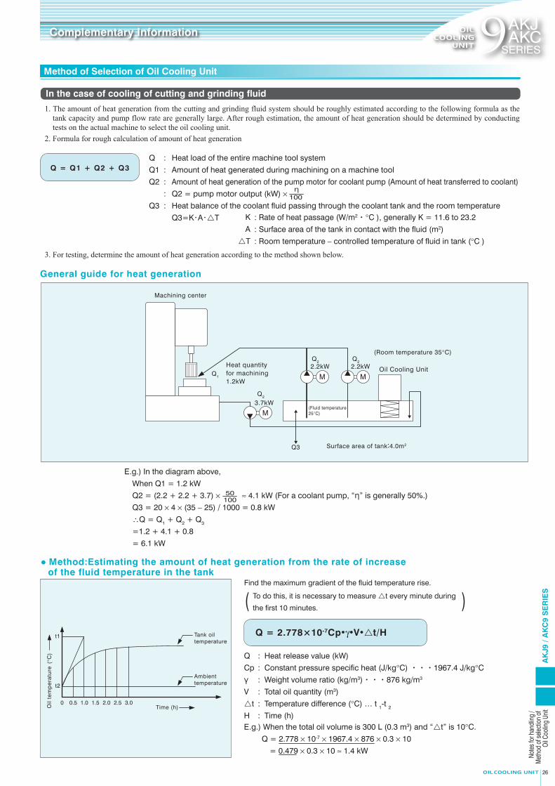
上海分公司(Shanghai Branch)DAIKIN HYDRAULICS (SUZHOU) CO., LTD.
◎
◎
◎
大連分公司(Dalian Branch)DAIKIN HYDRAULICS (SUZHOU) CO., LTD.◎
北京営業所(Beijing Office)DAIKIN HYDRAULICS (SUZHOU) CO., LTD.◎
広州営業所(Guangzhou Office)DAIKIN HYDRAULICS (SUZHOU) CO., LTD.◎
瀋陽営業所(Shenyang Office)DAIKIN HYDRAULICS (SUZHOU) CO., LTD.◎
◎
KD HYDRAULICS,LTD.
HO TAI DEVELOPMENT CO.,LTD.
SIAM DAIKIN SALES CO., LTD.
ZICOM PRIVATE LTD.
DAIKIN AIR CONDITIONING INDIA PVT.LTDDELHI BRANCH
ALL WORLD MACHINERY
Please contact Daikin Sales Counter for servicing of Oil Cooling Unit in countries outside Japan.
Country/Region Company name
◎Sales agents of hydraulic equipment.Others are the sales agent of air conditioning equipment.
(As of Oct. 30, 2015)
Locations
Overseas service network
China
Korea
Taiwan
Thailand
Singapore
India
U.S.
Beijing
Shanghai
Dalian
Guangzhou
Shenyang
Seoul
Taipei
Singapore
Bangkok
New Delhi
Illinois
Daikin is ready to offer you service in conjunction with the sales agents of our Air-conditioning and Hydraulic Divisions located in seven countries and regions worldwide.
AKJ9 SERIES
AKC9 SERIES
GK248 (2015.12.020) DF.MD.MD●Contents in this catalog are subject to change for improvement without prior notice.
Circulating type
Immersion type
Oil Hydraulic Division
Oil Hydraulic Equipment
9AKJAKC
SERIES
Osaka OfficeYODOGAWA PLANT1-1, Nishi-Hitotsuya, Settsu, Osaka 566-8585, Japan
Home Page: http://www.daikinpmc.com/en/
AKJ9 SERIESCirculating typeImmersion type
9AKJAKC
SERIES
AKC9 SERIESAKJ9 SERIES AKC9 SERIES
Oil Hydraulic Division
I N D E XAKJ9 SERIES (Immersion type)
Overview / Features
System OverviewPiping System Diagram
Nomenclature
Specifications and Operating range
Cooling Capacity Characteristic Chart
External Dimension Diagram
Installation Dimension Diagram
Pages 1 to 2
Pages 3
Pages 4
Pages 5 to 6
Pages 7 to 8
Pages 9 to 11
Pages 12
AKC9 SERIES (Circulating type)
Pages 13
Pages 13
Pages 14
Pages 14
Pages 15
Pages 15
Pages 15
Pages 16
Overview/Features
System Configuration
Optional Parts
Pages 17
Pages 18
Thermistor
Extension board for main machine communication
Nomenclature
Specifications
Cooling Capacity Characteristic Chart
Internal Pressure Loss
External Dimension Diagram
Flow Rate Characteristics for Models With a Pump
Supporting Information
Pages 19
Pages 20
Pages 21 to 22
Pages 23
Pages 24 to 25
Pages 26
Control Panel
Operation Mode/Setting Method
Electric Schematic Diagram
Electric Wiring Connection Instruction Diagram
Notes for handling
Method of selection of Oil Cooling Unit