alfa+romeo+selespeed
DESCRIPTION
Alfa+Romeo+SelespeedTRANSCRIPT
Alfa Romeo Selespeed
Introduction
The concept of the Selespeed transmission system for Alfa Romeo 147 follows the
aim already developed on the Alfa Romeo 156 from which it originates. The aim is
to improve performance of the manual gearbox transmission components.To avoid
that the driver has to check the clutch pedal and the gear control lever but at the
same time ensuring the driving pleasure that comes from direct control of
transmission.To improve driving safety by a direct control that foresees the errors
of the driverand prevents an incorrect control of the transmission system. Offers
the driver a more advanced car interface.It should be remembered that the
system essentially consists of a mechanical transmission, with dry monodisk clutch
and synchronised mechanical gear, moved by hydraulic power.As previously with
the Alfa Romeo 156, neither the clutch nor the gearbox is changed to install the
hydraulic actuators that control the stroke of the clutch and the gear engagement
and selection.An electronic control unit manages a complex functioning logic that
permits the use of the gearbox:
• in "semi-automatic" conditions, where the driver controls the gear engagement by the lever
on the tunnel or with two push-buttons.
• In "automatic" mode, called "City" that assigns the decision to change gear to the electronic
system. The clutch pedal has been eliminated, the traditional "H" gear lever of manual
transmission has been replaced by a specific "Joystick" lever and two "UP-DOWN" buttons on
the steering wheel.
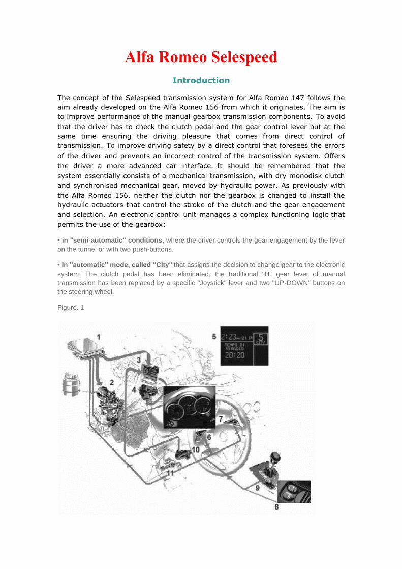
Figure. 1

1. Control unit
2. Electro-hydraulic group with electric pump
3. Engine control unit (Bosch M7.3.1)
4. Motorised throttle case (D.V.E.)
5. Gear selection display
6. Down-gear button (Down)
7. Up-gear button (Up)
8. "City" mode button
9. Gear control selection lever
10. Accelerator
11. Switch on brake pedal
Power steering system that essentially consists of an electro-hydraulic group (2)
mounted directly onto the gearbox. By means of two pistons it manages the gear
selection and engagement.The two pistons are controlled by a group of solenoid
valves, to which an electric pump and an accumulator supply the required hydraulic
power.An electronic control unit (1) having identified the requirements of the
driver from the lever (9) or from buttons (6) and (7) autonomously manages the
gear change, directly controlling clutch, gearbox and engine torque. During the
gear shift the engine control is subordinated to the gear control.The gear -
engine interface considerably improves the system performance and relieves the
driver of any need to synchronise the clutch-accelerator movements during the
gear change, that can be effected with the accelerator always fully pressed down.
Furthermore, the system inhibits incorrect requests to change gear and avoids
engine stalling.In terms of aid to driving it also ensures: immediate availability of
first gear when the vehicle stops; automatic downward gear change in the case of a
strong deceleration.The gear engaged is shown on a display built into the panel on
board (central display), whereas indications of faults or driving conditions critical for
the vehicle or for transmission components are indicated directly on the display
highlighting the text: Selespeed system fault, and, on the right of the panel the
gearbox fault symbol is shown.
Figure 2. Selespeed system components

Key
1. Gear selection lever
2. "City" button
3. Selespeed control unit (assembled in passenger compartment under the dashboard, passenger side)
4. Gear selection buttons on steering wheel
5. Electro-hydraulic group
6. Electric pump
7. Hydraulic oil pump
8. Speed sensor on gearbox
9. Gear selection display
10. Fault warning light
Selespeed system components
These are integrated to the manual transmission with no special modifications to
the clutch and the internal part of the gear, only the gearbox is changed to permit
the fastening of the hydraulic actuators that control the clutch and the gear
engagement selection.The clutch pedal has been eliminated, therefore for a
breakaway start only the accelerator pedal is used.By means of an electro-
hydraulic group, the electronic control unit manages gear engagement both in
semi-automatic and automatic mode.Semiautomatic, or manual, the driver
makes a direct gear change by activating the lever on the centre console or through
the buttons on the steering wheel.Automatic, also called "city", in this
configuration it is the system that makes the decision as to when to change gear.
The advantages are: the driver does not have to use the clutch pedal and the gear
shift lever, but is not deprived of the pleasure of driving that comes from direct
control of transmission.The CFC 208 is set to:
• acquire the signals coming from the different sensors
• interface with the engine control unit (Motronic M7.3.1)
• control the hydraulic system
• manage the information display and buzzer
The CFC 208F input signals are the following:
• rpm, (from rev. counter through Bosch Motronic control unit M7.3.1)
• gearbox input revs
• car speed (information to CAN line)
• clutch actuator position
• selector actuator position
• engagement actuator position
• key in travel position
• door switch status driver side
• brake pedal switch status
• electro-hydraulic group oil pressure
• CAN line signal (position of accelerator pedal, engine torque, water temperature, etc.)
• gear change request from buttons or lever
• +50 engine ignition.
The interface with C.C.M. M7.3.1 is managed on the CAN line.To control the
hydraulic actuation sub-system the CFC 208F has:
• 1 output to adjust the proportional flow-rate solenoid valve for clutch control
• 2 outputs to adjust the proportional pressure solenoid valve for gear engagement control
• 2 outputs to control the on/off solenoid valves to control selection
• 1 output to control the electric pump
• 1 output to control the ignition relay
The CFC 208F also gives the start enable.
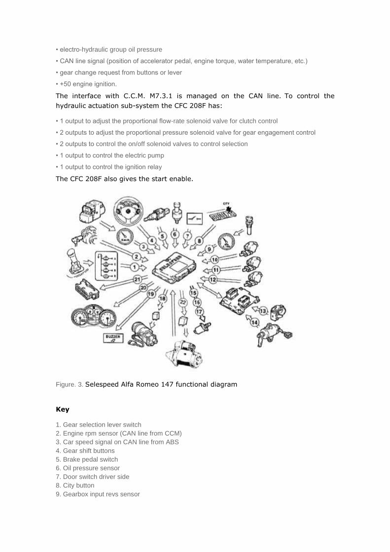
Figure. 3. Selespeed Alfa Romeo 147 functional diagram
Key
1. Gear selection lever switch
2. Engine rpm sensor (CAN line from CCM)
3. Car speed signal on CAN line from ABS
4. Gear shift buttons
5. Brake pedal switch
6. Oil pressure sensor
7. Door switch driver side
8. City button
9. Gearbox input revs sensor
10. Clutch position sensor
11. Gear selection position sensor
12. Gear engagement position sensor
13. DVE motorised throttle case ( CAN line from CCM)
14. Accelerator pedal potentiometer (CAN line from CCM)
15. Pressure proportional solenoid valves ( 2)
16. On-off solenoid valves (2)
17. Flow rate proportional solenoid valve
18. Electric pump
19. Buzzer
20. On-board panel
21. Diagnostics socket
22. Start enable relay
Hydraulic system
The hydraulic system is the part of the Selespeed that in the practical sense, has the task of the selection - engagement of the required gear.Basically it consists of:
• A power group to pressurise the circuit
• Two actuators to control the gear shaft
• An actuator to control the clutch
• Sensors for system monitoring by the control unit
The hydraulic system has these functions:
1. To supply the hydraulic energy needed to control the actuators
2. Gear shaft control
3. Clutch control
The fundamental function of the hydraulic system is to supply the hydraulic energy
to control the actuators (gear change).Therefore the possibility to change gear is
tightly bound to the pressure of the oil in the circuit, with values between 45 and
55 bar (653 to 798 psi).The main technical specifications that are necessary for
the system to ensure correct operation are:
• Hydraulic working pressure between 45 and 55 bar (there is a pressure relief valve to avoid system over-pressure)
• Working temperature between -30°C and +125°C
• Starting must also be possible with a temperature of -30°C
• The pump flow rate must be 0.8l/min at 60°C
• The accumulator volume must be 350 cm3 at 20°C (this value is important because it determines the discharge time)
• The oil used is Tutela CS Speed.
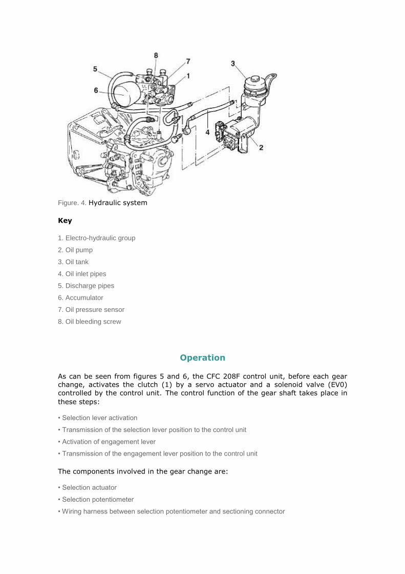
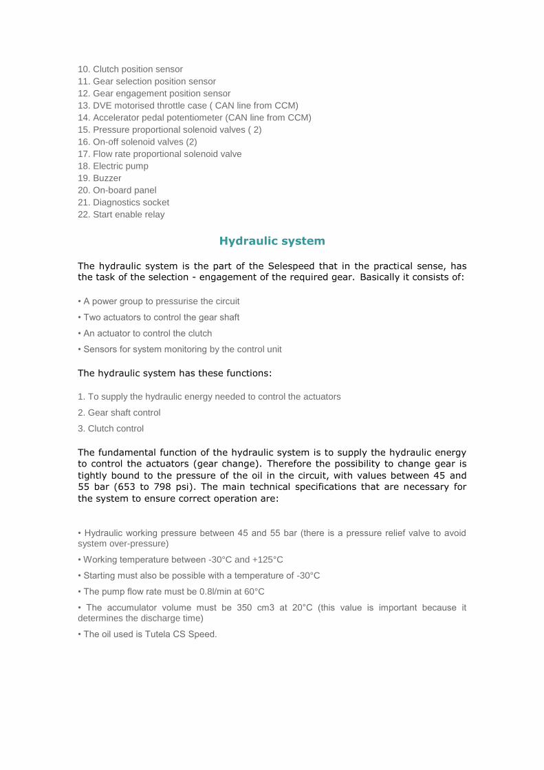
Figure. 4. Hydraulic system
Key
1. Electro-hydraulic group
2. Oil pump
3. Oil tank
4. Oil inlet pipes
5. Discharge pipes
6. Accumulator
7. Oil pressure sensor
8. Oil bleeding screw
Operation
As can be seen from figures 5 and 6, the CFC 208F control unit, before each gear
change, activates the clutch (1) by a servo actuator and a solenoid valve (EV0)
controlled by the control unit.The control function of the gear shaft takes place in
these steps:
• Selection lever activation
• Transmission of the selection lever position to the control unit
• Activation of engagement lever
• Transmission of the engagement lever position to the control unit
The components involved in the gear change are:
• Selection actuator
• Selection potentiometer
• Wiring harness between selection potentiometer and sectioning connector

• Selection solenoid valve EV3
• Wiring harness between selection solenoid valve EV3 (gear selection range 1-2) and the sectioning connector
• Selection solenoid valve EV4
• Wiring harness between selection solenoid valve EV4 (gear selection range 5 - R) and the sectioning connector
• Gear engagement actuator
• Engagement potentiometer
• Wiring harness between engagement potentiometer and sectioning connector
• Engagement solenoid valve EV1 (to engage odd gears 1-3-5)
• Wiring harness between engagement valve EV1 and the sectioning connector
• Engagement solenoid valve EV2 (to engage even gears 2-4-R)
• Wiring harness between engagement solenoid valve EV2 and sectioning connector.
Figure. 5. Section of clutch control - gearbox actuators
1. Clutch control lever on gearbox
2. Gear shaft (engagement and selection control)
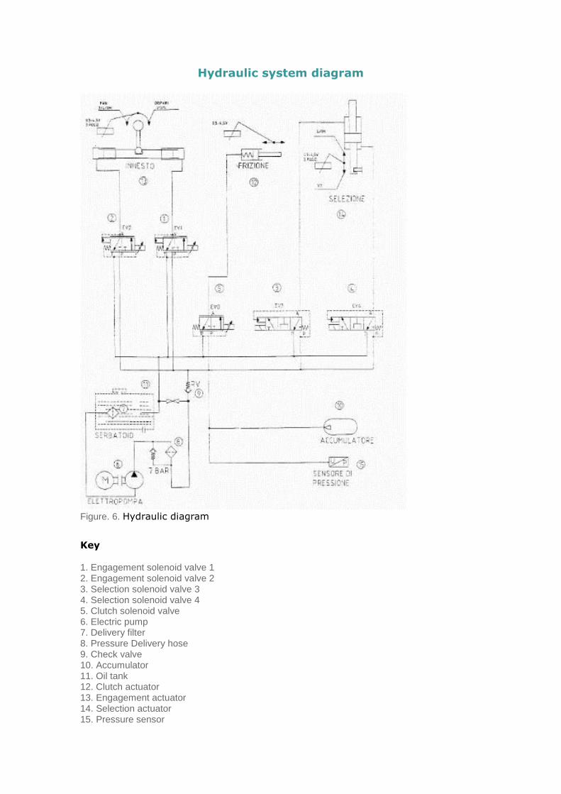
Hydraulic system diagram
Figure. 6. Hydraulic diagram
Key
1. Engagement solenoid valve 1 2. Engagement solenoid valve 2 3. Selection solenoid valve 3 4. Selection solenoid valve 4 5. Clutch solenoid valve 6. Electric pump 7. Delivery filter 8. Pressure Delivery hose 9. Check valve 10. Accumulator 11. Oil tank 12. Clutch actuator 13. Engagement actuator 14. Selection actuator 15. Pressure sensor

Electro-hydraulic group
This is one of the system components where the actuators, position sensors,
actuator solenoid valves have been incorporated, specifically connected by cables
that link them to a centralised multiple connector.This solution simplifies and cuts
down assembly time on the gearbox and avoids connection errors. Furthermore the
actuator solenoid valve cables all have identification labels.
Figure. 7. Electro-hydraulic group
5. EV4
6. EV3
1.
2.
8.
10.
..
17.
18.

Figure. 8.
The electro-hydraulic group consists of:
1. A casting casing fastened on the gearbox 2. Single action actuator to activate the clutch lever 3. Proportional pressure solenoid valve EV1 to control the engagement of the odd gears 1-3-5 4. Proportional pressure solenoid valve EV2 to control the engagement of the even gears 2-4-R 5. On-off solenoid valve EV4 to control 5-R gear selection 6. On-off solenoid valve EV3 to control 1-2 gear selection 7. Proportional flow-rate solenoid valve EV0 to control the clutch actuator 8. Hydraulic gas accumulator 9. Hydraulic circuit pressure sensor
3. EV1
4. EV2
6. EV3
5. EV4
1.
2.
8.
11.
12.
13. 18.
10. Sensor to detect clutch actuator position 11. Sensor to detect engagement actuator position 12. Sensor to detect selector actuator position 13. Bleed valve 14. Access to gear shaft actuators connecting screw 15. Union for oil delivery pipe 16. Union for oil return pipe 17. Connector for gearbox speed sensor 18. Selespeed wiring harness connector
The following are also installed in the electro-hydraulic group:
• a check valve • an oil inlet filter • screws fastening the engagement / selection actuator to the gearbox gear shaft.
Solenoid valves and actuators
The solenoid valves manage the oil flow to the actuator chambers.All the valves
are the three-way type, they are normally discharged when not controlled.
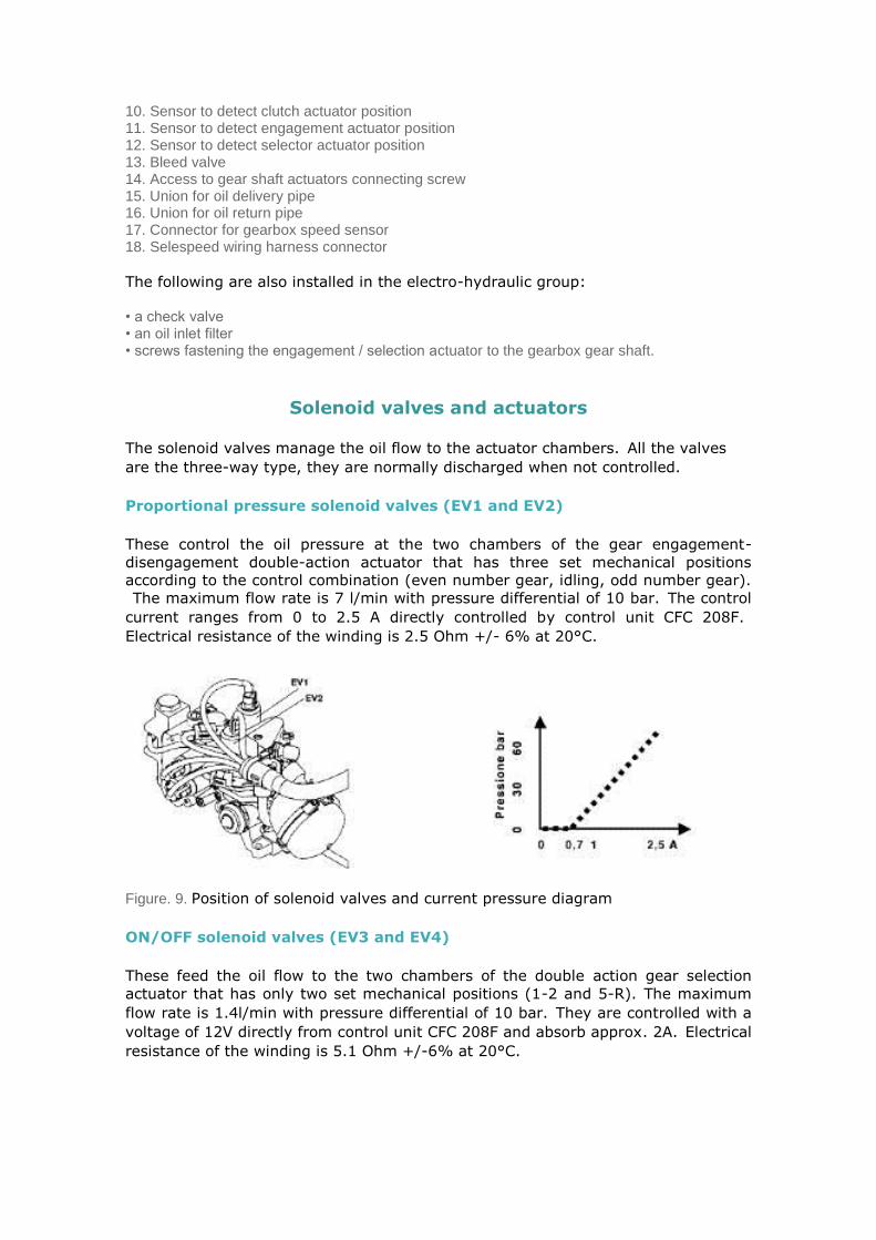
Proportional pressure solenoid valves (EV1 and EV2)
These control the oil pressure at the two chambers of the gear engagement-
disengagement double-action actuator that has three set mechanical positions
according to the control combination (even number gear, idling, odd number gear).
The maximum flow rate is 7 l/min with pressure differential of 10 bar.The control
current ranges from 0 to 2.5 A directly controlled by control unit CFC 208F.
Electrical resistance of the winding is 2.5 Ohm +/- 6% at 20°C.
Figure. 9. Position of solenoid valves and current pressure diagram
ON/OFF solenoid valves (EV3 and EV4)
These feed the oil flow to the two chambers of the double action gear selection
actuator that has only two set mechanical positions (1-2 and 5-R).The maximum
flow rate is 1.4l/min with pressure differential of 10 bar.They are controlled with a
voltage of 12V directly from control unit CFC 208F and absorb approx. 2A.Electrical
resistance of the winding is 5.1 Ohm +/-6% at 20°C.
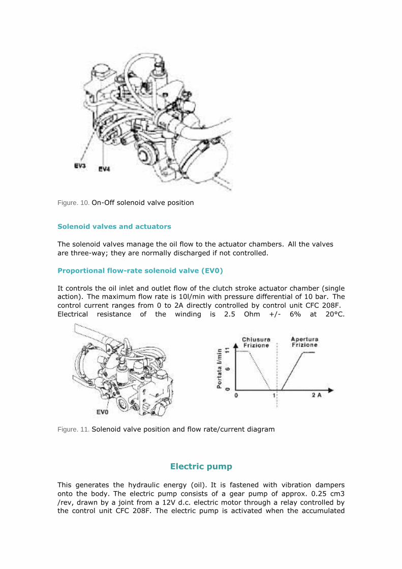
Figure. 10. On-Off solenoid valve position
Solenoid valves and actuators
The solenoid valves manage the oil flow to the actuator chambers.All the valves
are three-way; they are normally discharged if not controlled.
Proportional flow-rate solenoid valve (EV0)
It controls the oil inlet and outlet flow of the clutch stroke actuator chamber (single
action).The maximum flow rate is 10l/min with pressure differential of 10 bar.The
control current ranges from 0 to 2A directly controlled by control unit CFC 208F.
Electrical resistance of the winding is 2.5 Ohm +/- 6% at 20°C.
Figure. 11. Solenoid valve position and flow rate/current diagram
Electric pump
This generates the hydraulic energy (oil).It is fastened with vibration dampers
onto the body.The electric pump consists of a gear pump of approx. 0.25 cm3
/rev, drawn by a joint from a 12V d.c. electric motor through a relay controlled by
the control unit CFC 208F.The electric pump is activated when the accumulated
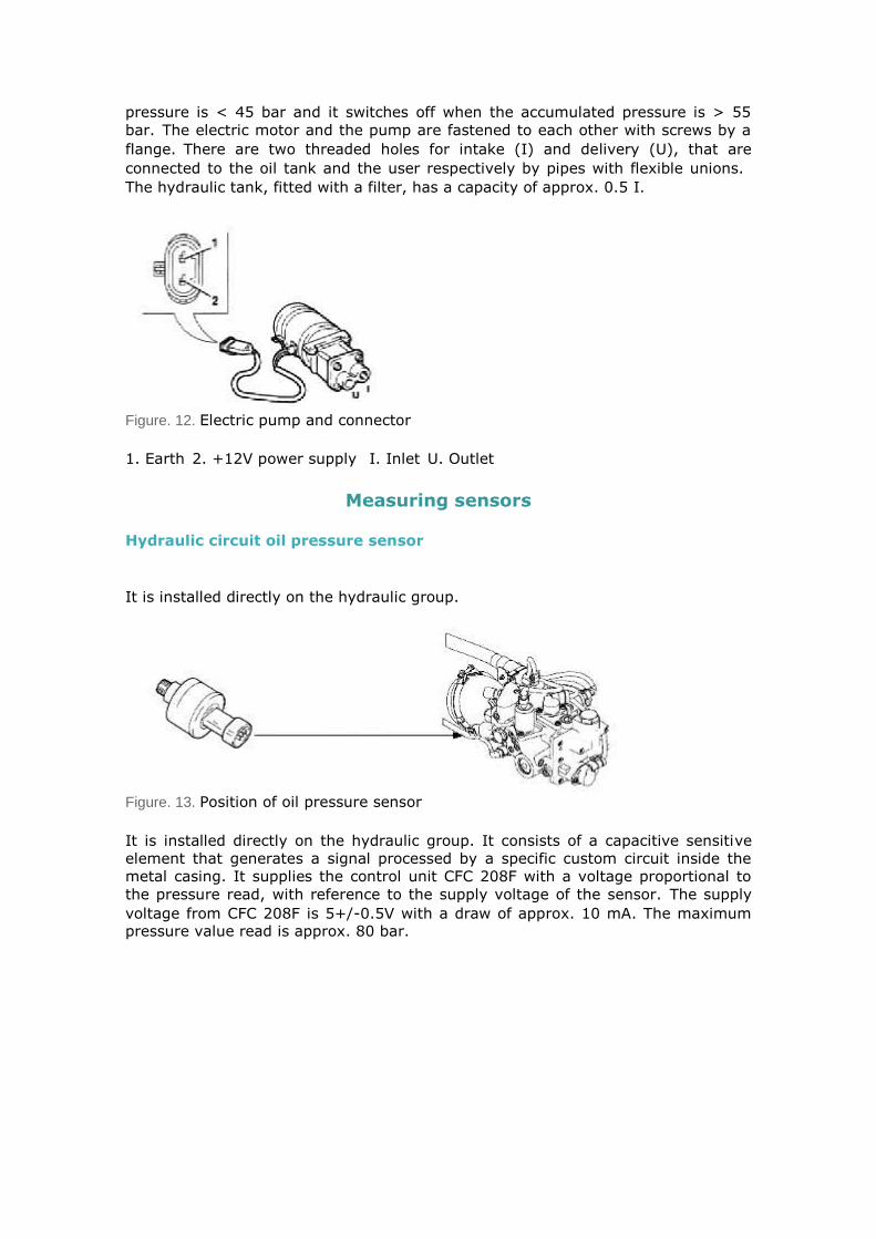
pressure is < 45 bar and it switches off when the accumulated pressure is > 55
bar.The electric motor and the pump are fastened to each other with screws by a
flange.There are two threaded holes for intake (I) and delivery (U), that are
connected to the oil tank and the user respectively by pipes with flexible unions.
The hydraulic tank, fitted with a filter, has a capacity of approx. 0.5 I.
Figure. 12. Electric pump and connector
1. Earth2. +12V power supply I. InletU. Outlet
Measuring sensors
Hydraulic circuit oil pressure sensor
It is installed directly on the hydraulic group.
Figure. 13. Position of oil pressure sensor
It is installed directly on the hydraulic group. It consists of a capacitive sensitive
element that generates a signal processed by a specific custom circuit inside the
metal casing. It supplies the control unit CFC 208F with a voltage proportional to
the pressure read, with reference to the supply voltage of the sensor.The supply
voltage from CFC 208F is 5+/-0.5V with a draw of approx. 10 mA. The maximum pressure value read is approx. 80 bar.

Figure. 14. Pressure sensor diagram
Actuators position sensor
Figure. 15. Actuators position sensor
The sensors that send the position of the gear selection, gear engagement and
clutch control actuators to the Selespeed control unit are single ramp
potentiometers installed directly on the electro-hydraulic group.They are powered
with 5V+/-0.5V by the control unit CFC 208F.Maximum resistance between pins A-
B is 1200 +/- 20 Ohm at 20°C.
Figure. 16. Location of actuator position sensors
The three sensors, of the same type, installed on the electro-hydraulic group are:
A. Gear selection position sensor
B. Gear engagement position sensor
C. Clutch position sensor
Clutch disk speed sensor (gearbox primary)
This is installed on the gearbox inlet, directly on the gear box.It is an
electromagnetic sensor and sends a sinusoidal signal to the control unit CFC 208F
that has a frequency in proportion to the speed of a pinion mounted on the gearbox

primary shaft. The winding resistance is 1200 Ohm +/- 10% at 20°C. The air gap
ranges between 0.2-1 mm.
Figure. 17. Gearbox speed sensor position
Switch on brake pedal
Installed on the brake pedal unit.
Figure. 18. Brake pedal switch
When the pedal is released it does not send any signal (NC) to the control unit CFC
208F. When the brake pedal is pressed the BRAKE lights switch on and the switch
sends the car braked signal (12V) to control unit CFC 208F.
Door open switch
This reads the information (ON-OFF) regarding the state of the driver side door,
sending an earth signal to the control unit CFC 208F when the door is open.

Driver's controls
Gear selection control lever
The lever has only one stable position (A) and 4 unstable (+, -, N, R).
Figure. 19. Gear selection lever
It has four normally open switches, each with two electric resistors (one in parallel
at contact, the other in series).To go to a higher gear, push the lever toward (+),
to have a lower gear, push toward (-).To insert idle (N) move the control lever to
the right Reverse gear (R) can be engaged from any gear, moving the gear lever
to the right then back, with the vehicle stationary and the brake pedal pressed.
Figure. 20. Gear selection lever electrical connection
Pin-Out CFC 208F functions
Figure. 21. Pin-Out CFC 208F functions
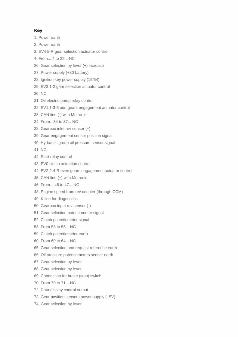
Key
1. Power earth
2. Power earth
3. EV4 5-R gear selection actuator control
4. From... 4 to 25... NC
26. Gear selection by lever (+) increase
27. Power supply (+30 battery)
28. Ignition key power supply (15/54)
29. EV3 1-2 gear selection actuator control
30. NC
31. Oil electric pump relay control
32. EV1 1-3-5 odd gears engagement actuator control
33. CAN line (-) with Motronic
34. From.. 34 to 37... NC
38. Gearbox inlet rev sensor (+)
39. Gear engagement sensor position signal
40. Hydraulic group oil pressure sensor signal
41. NC
42. Start relay control
43. EV0 clutch actuation control
44. EV2 2-4-R even gears engagement actuator control
45. CAN line (+) with Motronic
46. From... 46 to 47... NC
48. Engine speed from rev counter (through CCM)
49. K line for diagnostics
50. Gearbox input rev sensor (-)
51. Gear selection potentiometer signal
52. Clutch potentiometer signal
53. From 53 to 58... NC
59. Clutch potentiometer earth
60. From 60 to 64... NC
65. Gear selection and request reference earth
66. Oil pressure potentiometers sensor earth
67. Gear selection by lever
68. Gear selection by lever
69. Connection for brake (stop) switch
70. From 70 to 71... NC
72. Data display control output
73. Gear position sensors power supply (+5V)
74. Gear selection by lever
75. Gear selection (+) (-) from steering wheel switch
76. Engine start +50 signal
77. City switch
78. Connection for door button
79. Clutch position sensor power supply (+5V)
80. Buzzer control
NOTE: On the CAN line (Pin 33-45) the following signals are available: Accelerator
pedal position, engine torque, water temperature, car speed; whereas CFC 208
uses this line to control the on-board panel display and the torque requests to the
engine control when changing gear.
Electrical diagram
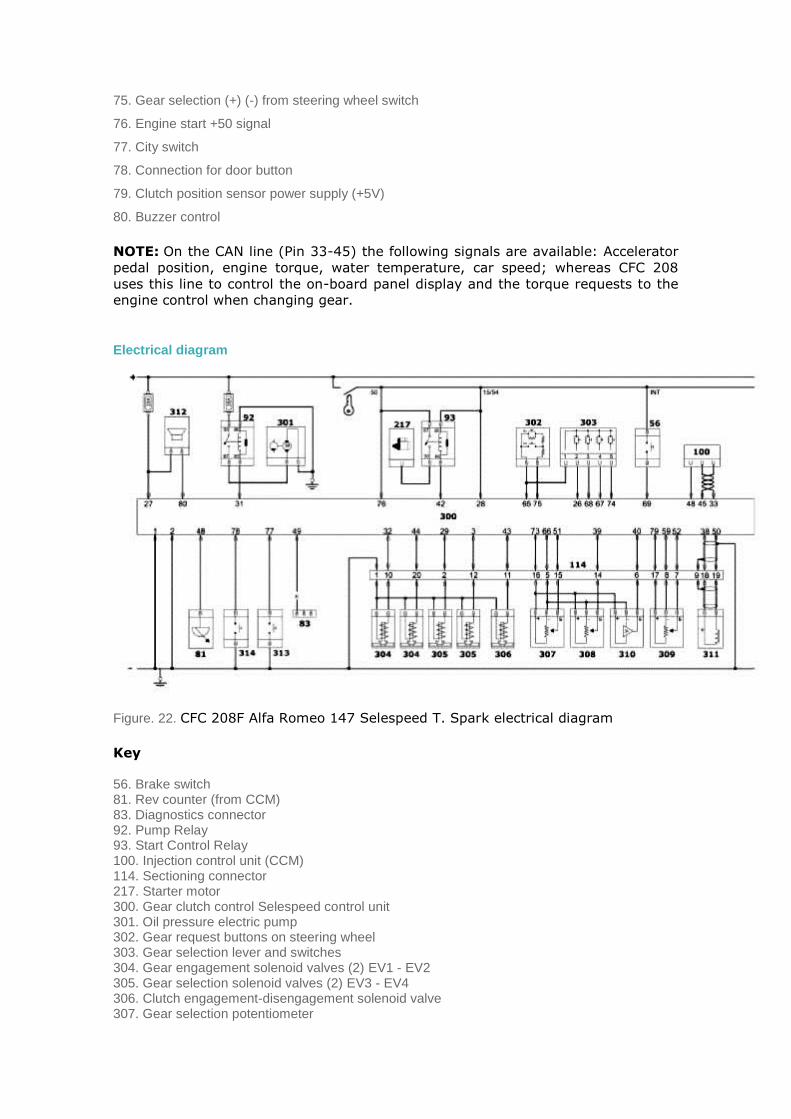
Figure. 22. CFC 208F Alfa Romeo 147 Selespeed T. Spark electrical diagram
Key
56. Brake switch 81. Rev counter (from CCM) 83. Diagnostics connector 92. Pump Relay 93. Start Control Relay 100. Injection control unit (CCM) 114. Sectioning connector 217. Starter motor 300. Gear clutch control Selespeed control unit 301. Oil pressure electric pump 302. Gear request buttons on steering wheel 303. Gear selection lever and switches 304. Gear engagement solenoid valves (2) EV1 - EV2 305. Gear selection solenoid valves (2) EV3 - EV4 306. Clutch engagement-disengagement solenoid valve 307. Gear selection potentiometer

308. Gear engagement potentiometer 309. Clutch potentiometer 310. Hydraulic group oil pressure sensor 311. Gearbox primary shaft speed sensor 312. Buzzer 313. City automatic gear mode button 314. Door button driver side
Overview of the Selespeed gearbox functioning
The Alfa Romeo 147 T. Spark engine, with electronically controlled manual
transmission is called Selespeed.This system is applied to a traditional manual
transmission, that has added an electronically controlled electro-hydraulic device
that automatically manages the clutch and the gear engagement.The gearbox can
function in two different operating modes:
1. Semiautomatic (or manual), where the driver makes the direct request to change gear through the lever on the tunnel or by pressing the buttons on the steering wheel.
2. Automatic (or City), where it is the system that decides when to change gear (this mode can be selected with the specific button).
The clutch pedal has been eliminated and take-off is by means of a control lever
with a "single stable central position" of the floating type that can be used to
increase/decrease the gear ratio engaged and the engagement of reverse gear (R)
and idling (N).There are also two buttons on the steering wheel spokes that can be
used when the vehicle is moving to increase/decrease the gear engaged.At every
activation by the turning of the key to MAR, the system always selects the
semiautomatic mode (manual).If, when the "automatic" (City) mode is running,
the driver requests a gear change, the system interprets this action as a request
from the user to have direct control, and switches to "Semiautomatic" mode.
Figure. 23. Steering wheel
The information regarding the gear engaged is shown on the display in the car
instrument panel (rev counter).
The symbols shown on the display are:
• N = idling • 1 = first gear • 2 = second gear • 3 = third gear • 4 = fourth gear • 5 = fifth gear • R = reverse

A fault warning light and a buzzer call the attention of the driver in the case of
faults or critical driving conditions for the vehicle or for the transmission
components (example: clutch over heating).
Selespeed considerably simplifies driving, and in town is less tiring, also in
situations where the gear has to be changed frequently, but at the same time it
ensures brilliant performance.
System activation
When the door on the driver's side is opened, Selespeed starts the hydraulic electric
pump to have the system ready for the engine ignition.This function can be
perceived by the electric pump rotating for a few seconds.When the engine ignition
key is turned to "MAR", all the gear display segments light up.After about one
second, the display indicates the gear engaged in the gearbox (N-1-2-3-4-5-R) and
the gearbox fault warning light switches off, indicating that the hydraulic system is
running and as from this moment the Selespeed system accepts gear change commands.
Functioning with engine off
Before moving the gear control lever the ratio of the gear engaged (N-1-2-3-4-5-R)
must be checked on the display.With the vehicle stationary and the brake pedal
pressed, gear change requests are accepted and effected "only" from the control
lever on the tunnel.To request a gear change, besides pressing the brake pedal, it
is necessary:
• To increase the gear (+) push the lever forward (if the car is in first gear it passes to second, if
it is in second gear it passes to third and so forth, up to fifth gear).If the system is idling (N) or
in reverse gear (R) pushing the lever forward engages the first gear.
• To decrease the gear (-) push the lever back (if the car is in fifth gear it passes to fourth, if it is in fourth it passes to third and so forth down to first gear).
Figure. 24. Engagement control lever (+), (-)
To set the gear to idling (N) with the vehicle stationary and the brake pedal
pressed, move the gear control lever to the right.

Figure. 25. Control lever (in "idle" position)
From any gear, (N-1-2-3-4-5-R) with the vehicle practically still, the reverse gear
can be engaged by pushing the lever to the right and then backward.If the vehicle
is moving, the request is not accepted.Wait for the vehicle to stop then engage the
reverse gear again.
Figure. 26. Control lever (engaging the reverse gear)
After the gear has been changed, release the control lever immediately.
A prolonged manoeuvre (more than 6 s) causes the gearbox fault warning light to
switch on, the sounding of the buzzer and the automatic change-over to "City"
mode. All this disappears when the gear lever is released. If the car is to be left on
a sloping road and you want to engage a gear to keep it braked, it is most
important to check on the display the indication of the new gear engaged, then wait
1 or 2 seconds before releasing the brake pedal to allow the clutch to engage
completely. If the car is in idle gear, the driver will hear the buzzer sound.
Engine start-up
The engine start-up can take place with the brake pedal pressed, either with the
gear engaged or with the gearbox already in idle (N).With the engine running, the
gearbox shows the letter (N) and the system sets the semi-automatic operation
(manual).
Shutting off the engine and system deactivation
When the ignition key is turned to "STOP" the engine switches off and the
Selespeed system remains active until the car stops completely.After 2/4 seconds,
with the key on STOP the hydraulic part deactivates and the gears display on the
panel switches off immediately. Only at this point the Selespeed system is no
longer active.The gear ratio selected before the shut-down remains engaged.If
the engine stops with the gear in idle, the buzzer calls the attention of the driver to
put the car in safety condition engaging the first gear (1) or the reverse gear (R).
In this case, the ignition key has to be turned to MAR and with the brake pedal
pressed request of the first gear (1) or reverse gear (R).
NOTE: Never leave the car with the gear in idle (N).Never remove the key while
the car is moving because, besides the fact that the system would function in an
anomalous way until the vehicle stops, the steering wheel would automatically lock
at the first swerve.The engine must be shut off, and as a consequence the
Selespeed deactivated, keeping the brake pedal pressed and only releasing it when
the rev counter display switches off.
Car start
With the engine on and the vehicle stationary the gears that can be engaged to
start are only the first (1), the second (2), and/or reverse (R).To engage the gear,
just use the control lever on the tunnel keeping the brake pedal pressed (the
buttons on the steering wheel only allow gear engagement at speeds over 10 Km/h.
• With the vehicle stationary and gear engaged still keep the brake pedal pressed until you actually move off.
• In long halts with the engine running it is advised to remain idling.
• If the car has to be parked uphill, do not use the take-off manoeuvre to keep the vehicle still, use the brake pedal and only use the accelerator pedal when you decide to move off.
• Only use the second gear when it is necessary to have better control of the take-off in manoeuvres with poor grip.
• If, with reverse gear engaged, the first gear is to be inserted, or vice-versa, wait until the vehicle is completely still before operating, and keep the brake pedal pressed.
Although it is most definitely advised against doing so, if when going downhill the
vehicle is allowed to proceed in idle gear (N), when the engagement of a gear is
requested the system will automatically engage, according to the speed of the car,
the best gear to have the correct transmission of the driving torque to the wheels.
If instead, the vehicle proceeds downhill with the gear engaged and the accelerator
released, when a set speed value is passed, the system will engage the clutch
automatically to give adequate engine braking to the car.For safety reasons the
system activates the warning buzzer when:
• If during the vehicle start-up manoeuvres the clutch overheats, in this case it is necessary to "force" the starting without hesitating, or otherwise release the accelerator and use the brake pedal to park the car on the slope.
• If the car goes forward in the opposite direction to the gear engaged (e.g. the vehicle goes forward with the reverse gear engaged). In this case stop the vehicle keeping the brake pedal pressed and engage the correct gear.
Still for safety reasons, with the car stationary, engine running and gear (1)-(2) or
(R) engaged, the system activates the buzzer and automatically puts the gear to
idling when:
• no operation is made on the accelerator pedal or the brake pedal for at least 60 s.
• the brake pedal is kept pressed for more than 3 min.
• the door on the driver's side is opened, after 2 seconds the car goes automatically into idling condition.
NOTE: The reverse gear (R) can be engaged from each of these ratios:
• Idle (N), - first (1) or second (2).
If the vehicle is moving, the request is not accepted, you must wait until the car is
completely still then request the reverse gear (R) engagement again.The reverse
gear engaged condition is indicated to the driver on the display and also by the
buzzer.In the same way, in the case of crawling on the reverse gear, the system
partially closes the clutch to favour the gear engagement.In this case the
engagement of the reverse gear will be less smooth.
After a gear change request with the vehicle stationary, before pressing the
accelerator pedal to start the car, the driver must always check on the display that
the gear engaged is the one wanted.
Car stop
To stop the car just release the accelerator pedal and if necessary act on the brake
pedal.Regardless of the gear engaged and the operating mode activated (Manual
or "City") the system automatically deactivates the clutch and lowers the gears in
the gearbox.If it is intended to start off again without having completely stopped
the car, the most suitable gear ratio will be available to accelerate again.When the
vehicle is stopped the system automatically engages the first gear.
Semiautomatic "Manual" operation
In "manual" mode, which is available every time the car is started, the display on
the panel indicates the gear engaged. In this operating mode the decision to
change the gear ratio depends on the driver who decides when it is the best
moment to engage it (unless in conditions of engine over speed/under speed) .The
requests to change gear take place through:
• the control lever on the tunnel.
• or when the car is moving at more than 10 Km/h, through the buttons on the steering wheel.

The "manual" operating mode is set:
• automatically at each car start up
• when the driver, with "CITY" mode selected: acts on the control lever on the tunnel or on the buttons on the steering wheel
• presses the "CITY" button again, thus switching off the mode previously selected.
Figure. 27. Control lever and City button
During the gear change it is not necessary to release the accelerator pedal because
the Sele-speed system, through the engine control unit, asks to:
• reduce then increase the engine torque
• adjust the engine rotation speed to the new ratio engaged in the gearbox.
When shifting down the gear, the so-called "double clutching" is executed
automatically (acceleration of the engine to bring it to the required speed) with the
new gear ratio.The command to set to idling (N) is accepted so long as the car
does not exceed 40 Km/h, with the foot on the brake.With the accelerator pedal
pressed down over 60% of its stroke, and engine speed over 5500 RPM, the gear
change is faster.In the "manual" mode there are some automatisms/safety devices
that facilitate the driving.
• When slowing down the clutch is opened and the gear ratio is automatically reduced so as to be ready for a possible return to the gear.
• Gear change requests are not accepted that would bring the engine over the maximum speed or below the minimum speed allowed.
• If the engine reaches the maximum speed allowed and the driver continues to accelerate, the system will automatically engage a higher gear.
• If, when engaging the gear there is crawling at the gearbox, first of all the system tries again to engage the requested gear, and if this still is not possible, automatically engages the next one up so that the car does not remain in idle gear.
NOTE: It is best to wait until a gear shift has terminated before asking for another,
to avoid multiple requests in quick succession.

Automatic "CITY" operation
The automatic "CITY" mode is selected by pressing the button on the base of the
gear lever.On the display in the rev counter, besides indicating the gear, the word
CITY is shown.It is then the system that decides when to change gear according to
the engine rpm and when the accelerator pedal is pressed.If the accelerator pedal
is released quickly, the system does not engage a higher gear to keep an adequate
engine brake level.If there is a fault on the gear control lever, the system passes
automatically to the automatic "CITY" mode, so that the car can return home.
Fault warnings
The Selespeed gearbox faults are indicated on the display on the instrument panel.
For some faults, besides the information on the display a buzzer warning is sounded
intermittently for 4 s to call the attention of the driver.If there is a fault on the
gear control lever, the system automatically inserts the automatic "CITY" mode so
as to be able to reach the nearest dealership to have the fault removed.For faults
on other components of the gearbox, the system allows only the engagement of
some ratios : first gear, second gear and reverse gear .
Warnings with buzzer
The buzzer is activated when:
• The vehicle is parked with the gear in idle; the indication can be detected turning the ignition key to STOP.
• During the take-off movement the clutch overheats.
• The system automatically engages the gearbox in idle after which:
. no movement is made on the accelerator pedal or the brake pedal for at least 60 sec.
. the brake pedal is pressed for over 3 min.
. the driver's door is opened without commands on the accelerator or on the brake.
• a gearbox fault has been found.
• a start-up attempt is made with gear engaged without pressing the brake.
Bump start
If there is a system fault a bump start can be made in this way:
• carry out the operation to activate the system (turning the ignition key to MAR).
• after 10 seconds, check that the warning light is off.
• while the car picks up speed with the gear in idle (N) use the control lever on the tunnel, to engage a higher gear.

Remember that bump starting or using downhill roads should be avoided because these manoeuvres, if the engine control system is not functioning properly, could cause fuel to flow into the catalyst and cause permanent damage.
Moreover, until the engine is running, power steering and brake booster are not efficient regarding functioning and driving safety.
If the battery is completely discharged, this type of start-up is not possible.
Parking the car
To park the car safely the first gear or reverse gear must be engaged, and if the
road slopes, engage the hand brake also.When the engine is switched off (key on
STOP) with the vehicle facing uphill and the gear engaged, you must wait until the
gears display on the on-board panel switches off before releasing the brake pedal,
so that the clutch is fully closed.If the idle gear is engaged and you want to
engage a parking gear, you must start the system (key ON) and with your foot on
the brake pedal engage the first gear or reverse gear.
Towing the vehicle
To tow the vehicle observe the current ruling.Make sure that the gear is in idle
(check that the car moves when pushed) and operate in the same way as with a
manual transmission car, following the indications in the chapter "in an emergency"
in the owner's handbook.If it is not possible to set the gear to idle do not tow the
car.
When the car is being towed do not start the engine.
Routine Maintenance
Selespeed oil level
Sele-speed system oil level must be checked with the car level and the engine cold.
To check the level, proceed as follows:
• Turn the ignition key to MAR.
• Detach the bleeder pipe and remove the cap, and check that the level is at the MAX level on the dip stick that is integral with the cap.
• If the oil is below the MAX level, top up until the correct level is reached.
• After screwing the cap back on, insert the bleeder pipe fully onto the cap tip and turn the ignition key to STOP.
Use only "Tutela CS Speed" oil for topping up
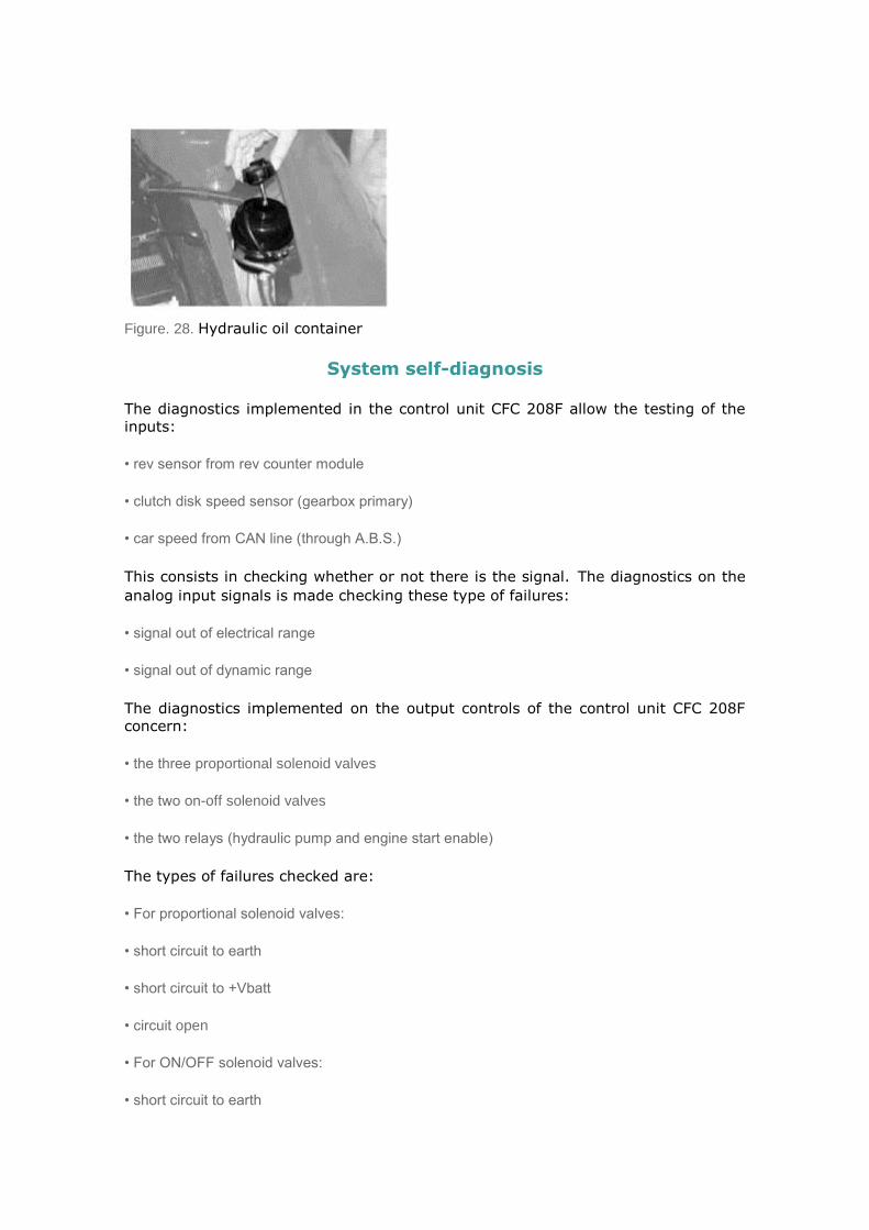
Figure. 28. Hydraulic oil container
System self-diagnosis
The diagnostics implemented in the control unit CFC 208F allow the testing of the
inputs:
• rev sensor from rev counter module
• clutch disk speed sensor (gearbox primary)
• car speed from CAN line (through A.B.S.)
This consists in checking whether or not there is the signal.The diagnostics on the
analog input signals is made checking these type of failures:
• signal out of electrical range
• signal out of dynamic range
The diagnostics implemented on the output controls of the control unit CFC 208F
concern:
• the three proportional solenoid valves
• the two on-off solenoid valves
• the two relays (hydraulic pump and engine start enable)
The types of failures checked are:
• For proportional solenoid valves:
• short circuit to earth
• short circuit to +Vbatt
• circuit open
• For ON/OFF solenoid valves:
• short circuit to earth

• Electric pump relay:
• circuit open
• short circuit to +Vbatt
• Start-up enable relay
• short circuit to earth
• circuit open
These input signals and output commands are excluded from the diagnosis:
• brake pedal (except permanent closed circuit for a certain time with car moving)
• automatic mode (CITY) and door open switches
• the signals supplied by C.C.M. on CAN network
• diagnostics serial line (K)
• signals : key (+15/54) power supply, (+30) direct from battery.
Faulty component and down-grade performance table
The gearbox check control unit diagnosis, after ascertaining a fault takes action
regarding the down-grade functioning. This data is indicated referring to the faulty component, in the table below:
FAULTY
COMPONENT
Fault
warning
light
DOWN GRADING
Gear engagement
solenoid valves
(proportional)
On Gear shift acceptance locked, gear engagement
excluding idle (N) (vehicle stationary)
Gear selection
solenoid valve
(ON/OFF)
On Gear shift acceptance locked, gear engagement
excluding idle (vehicle stationary)
Engagement and
selection position
sensors
On Long time for gear shift.
Gear shift acceptance limited to 1, 2, R, N
Rev sensors: engine,
gear input and gear
output (car speed)
On Gear shift acceptance limited to 1, 2, R, N
Oil pressure sensor On Electric pump control in open-loop
Gear request lever
switches On
Switching in automatic mode "CITY", cannot engage
R
Buttons on steering
wheel switches On Does not accept commands from steering wheel
Clutch solenoid valve
(proportional) On
Clutch control lock, automatic shift to idle (N)
(vehicle stationary)
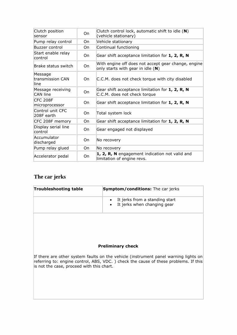
Clutch position
sensor On
Clutch control lock, automatic shift to idle (N)
(vehicle stationary)
Pump relay control On Vehicle stationary
Buzzer control On Continual functioning
Start enable relay
control On Gear shift acceptance limitation for 1, 2, R, N
Brake status switch On With engine off does not accept gear change, engine
only starts with gear in idle (N)
Message
transmission CAN
line
On C.C.M. does not check torque with city disabled
Message receiving
CAN line On
Gear shift acceptance limitation for 1, 2, R, N
C.C.M. does not check torque
CFC 208F
microprocessor On Gear shift acceptance limitation for 1, 2, R, N
Control unit CFC
208F earth On Total system lock
CFC 208F memory On Gear shift acceptance limitation for 1, 2, R, N
Display serial line
control On Gear engaged not displayed
Accumulator
discharged On No recovery
Pump relay glued On No recovery
Accelerator pedal On 1, 2, R, N engagement indication not valid and
limitation of engine revs.
The car jerks
Troubleshooting table Symptom/conditions: The car jerks
It jerks from a standing start It jerks when changing gear
Preliminary check
If there are other system faults on the vehicle (instrument panel warning lights on
referring to: engine control, ABS, VDC. ) check the cause of these problems. If this
is not the case, proceed with this chart.

DIAGNOSTICS
Test results
Step Operations
0 Check oil level All OK Problems
found Intervention
Check oil level as shown in
Procedure 2
Go to
step 1
Level other
than max
Do Procedure 3
1 Check oil pressure All OK Problems
found Intervention
Check oil pressure as
shown in Procedure 4.
Go to
step 2
Press < 40
bar
Do Procedure 5
2 Check for Errors All OK Problems
found Intervention
Check ECU for absence of
errors. Specifically check
for:
Clutch position
sensor
Errors CAN
messages
(reception/transmission)
Go to
step 4
Presence of
one or more
errors
included in
the list
Go to step 3
3 Check problems found All OK Problems
found Intervention
Check problems according
to Procedure 17
End of
procedure
The problem
persists
Go to step 4
4 Bleed the system with
Examiner All OK
Problems
found Intervention
In active diagnosis run two
system bleeding cycles
through the "clutch
bleeding" command
Go to step 5
5
Clutch parameters
calibration with
Examiner
All OK Problems
found Intervention
With examiner in active
diagnosis, run the
calibration of the clutch
parameters through
Go to step 6

" enable clutch self-
calibration ".
6 Road test All OK Problems
found Intervention
Check that the fault is no
longer present by testing
on the road
End of
procedure
The problem
persists
Go to step 7
7 The problem persists All OK Problems
found Intervention
Check that the problem is
not caused by other
systems such as the
engine, fuel supply, etc.
Go to
step 8
There are
faults on
other car
systems.
See the specific charts.
8 The problem persists All OK Problems
found Intervention
Contact technical
assistance for additional
information on the
problem
Noisy gearbox
Troubleshooting table Symptom/conditions: Noisy gearbox
The gear grates
DIAGNOSTICS
Test results
Step Operations
0
Check that the
clutch does not
drag
All OK Problems
found Intervention
Check that the
clutch does not drag
following Procedure
14
Go to step 2 The clutch
drags
Overhaul the
clutch/flywheel kit and
replace the broken
components. Go to step 1.

1 After intervening
on the clutch kit All OK
Problems
found Intervention
Check that the
problem is no longer
present.
End of
procedure
The problem
persists
Go to step 2
2 The problem
persists All OK
Problems
found Intervention
The problem
persists
Contact technical
assistance for additional
information on the problem
The car doesn't start
Troubleshooting table Symptom/conditions: The car doesn't start
The engine doesn't start up
The display indicates the gear engaged and doesn't go to idle to allow starting
Preliminary check
If, when starting the engine, it is noted that the starter motor functions normally,
the problem is caused by other systems (engine control, ABS, fuel pump.). See the
specific charts. If the starter motor doesn't start continue following this diagnosis chart
DIAGNOSTICS
Test results
Step Operations
00 Start enable check All OK Problems
found Intervention
With the car running
in idle and with
Examiner in
parameters
environment, select
start and check that
it is allowed.
Starting is
allowed.
Check the
functioning
of the
starter
motor
Starting is not
allowed.
Go to step 0
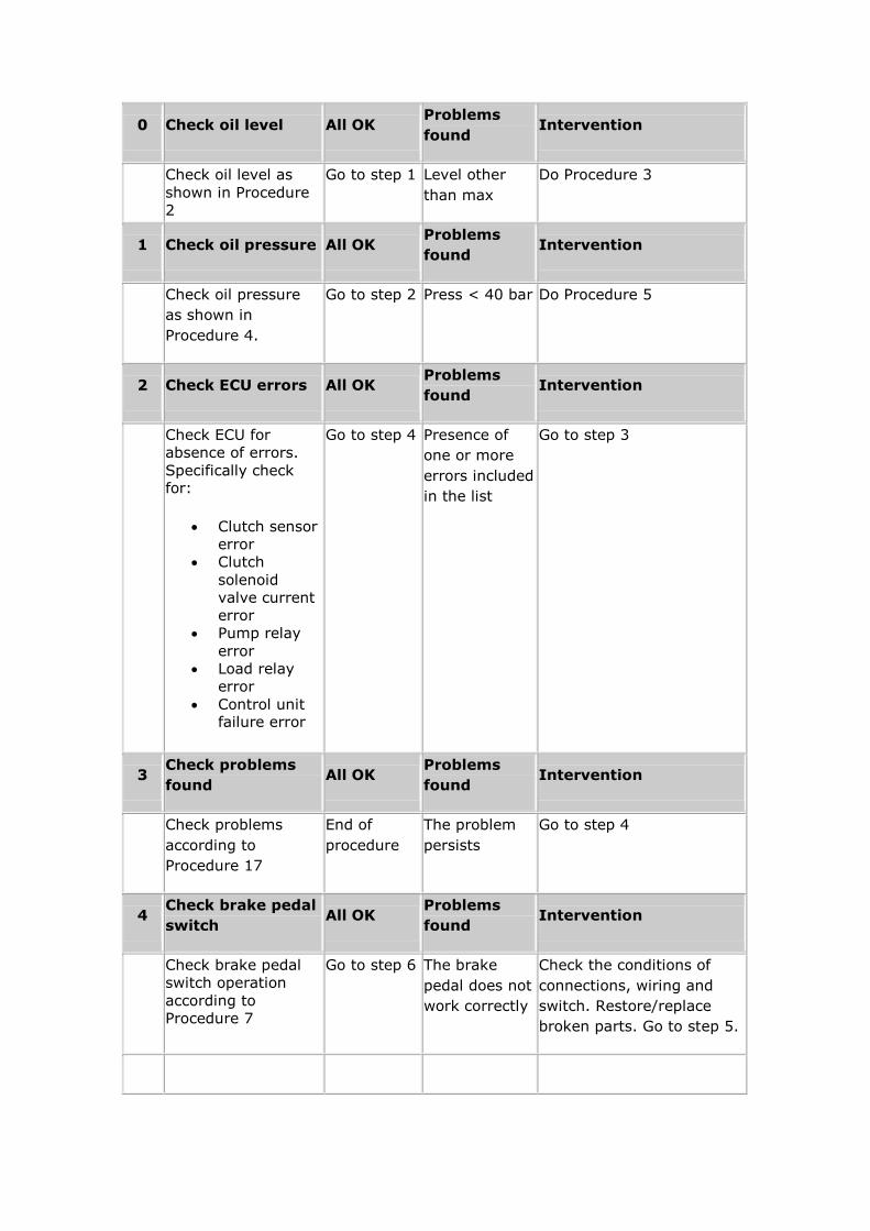
0 Check oil level All OK Problems
found Intervention
Check oil level as
shown in Procedure
2
Go to step 1 Level other
than max
Do Procedure 3
1 Check oil pressure All OK Problems
found Intervention
Check oil pressure
as shown in
Procedure 4.
Go to step 2 Press < 40 bar Do Procedure 5
2 Check ECU errors All OK Problems
found Intervention
Check ECU for
absence of errors.
Specifically check for:
Clutch sensor
error
Clutch
solenoid
valve current
error
Pump relay
error
Load relay
error
Control unit failure error
Go to step 4 Presence of
one or more
errors included
in the list
Go to step 3
3 Check problems
found All OK
Problems
found Intervention
Check problems
according to
Procedure 17
End of
procedure
The problem
persists
Go to step 4
4 Check brake pedal
switch All OK
Problems
found Intervention
Check brake pedal
switch operation
according to
Procedure 7
Go to step 6 The brake
pedal does not
work correctly
Check the conditions of
connections, wiring and
switch. Restore/replace
broken parts. Go to step 5.
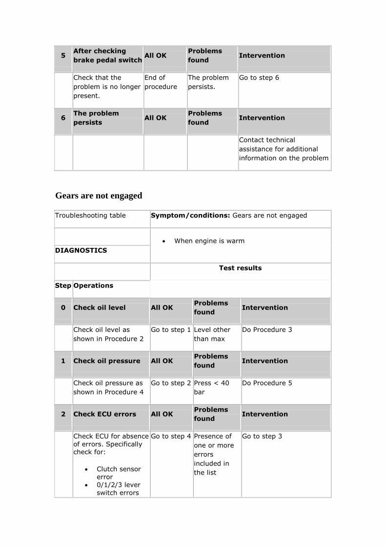
5 After checking
brake pedal switch All OK
Problems
found Intervention
Check that the
problem is no longer
present.
End of
procedure
The problem
persists.
Go to step 6
6 The problem
persists All OK
Problems
found Intervention
Contact technical
assistance for additional
information on the problem
Gears are not engaged
Troubleshooting table Symptom/conditions: Gears are not engaged
When engine is warm
DIAGNOSTICS
Test results
Step Operations
0 Check oil level All OK Problems
found Intervention
Check oil level as
shown in Procedure 2
Go to step 1 Level other
than max
Do Procedure 3
1 Check oil pressure All OK Problems
found Intervention
Check oil pressure as
shown in Procedure 4
Go to step 2 Press < 40
bar
Do Procedure 5
2 Check ECU errors All OK Problems
found Intervention
Check ECU for absence
of errors. Specifically check for:
Clutch sensor
error
0/1/2/3 lever
switch errors
Go to step 4 Presence of
one or more
errors
included in
the list
Go to step 3
Even gear
engagement
error
Odd gear
engagement
error
Clutch solenoid
valve current
error
1^/2^range
selection
solenoid valve
error
5^/R range
selection
solenoid valve
error
ECU earth error
Load relay error
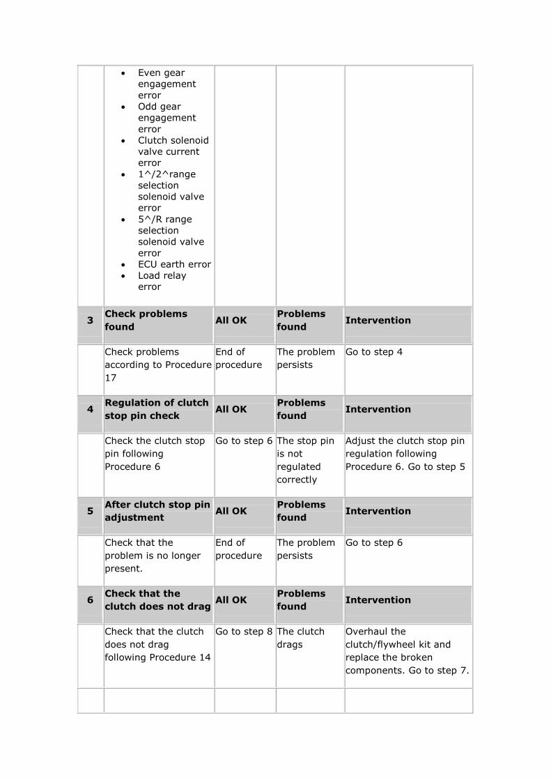
3 Check problems
found All OK
Problems
found Intervention
Check problems
according to Procedure
17
End of
procedure
The problem
persists
Go to step 4
4 Regulation of clutch
stop pin check All OK
Problems
found Intervention
Check the clutch stop
pin following
Procedure 6
Go to step 6 The stop pin
is not
regulated
correctly
Adjust the clutch stop pin
regulation following
Procedure 6. Go to step 5
5 After clutch stop pin
adjustment All OK
Problems
found Intervention
Check that the
problem is no longer
present.
End of
procedure
The problem
persists
Go to step 6
6 Check that the
clutch does not drag All OK
Problems
found Intervention
Check that the clutch
does not drag
following Procedure 14
Go to step 8 The clutch
drags
Overhaul the
clutch/flywheel kit and
replace the broken
components. Go to step 7.
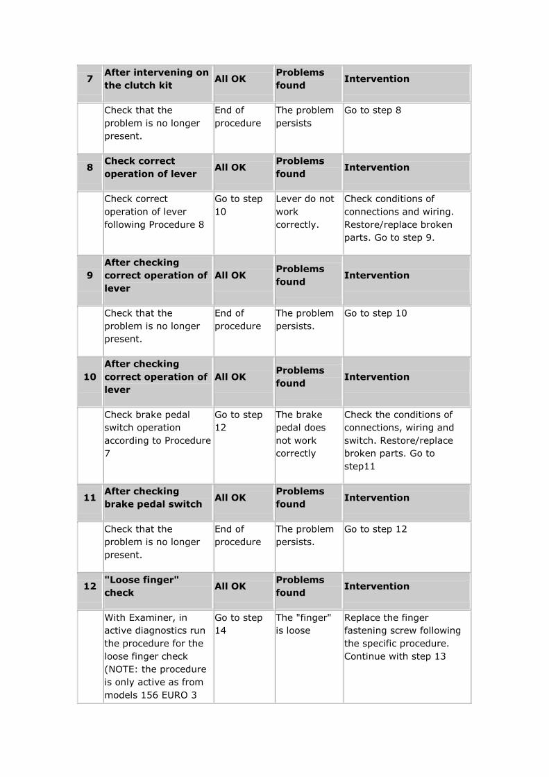
7 After intervening on
the clutch kit All OK
Problems
found Intervention
Check that the
problem is no longer
present.
End of
procedure
The problem
persists
Go to step 8
8 Check correct
operation of lever All OK
Problems
found Intervention
Check correct
operation of lever
following Procedure 8
Go to step
10
Lever do not
work
correctly.
Check conditions of
connections and wiring.
Restore/replace broken
parts. Go to step 9.
9
After checking
correct operation of
lever
All OK Problems
found Intervention
Check that the
problem is no longer
present.
End of
procedure
The problem
persists.
Go to step 10
10
After checking
correct operation of
lever
All OK Problems
found Intervention
Check brake pedal
switch operation
according to Procedure
7
Go to step
12
The brake
pedal does
not work
correctly
Check the conditions of
connections, wiring and
switch. Restore/replace
broken parts. Go to
step11
11 After checking
brake pedal switch All OK
Problems
found Intervention
Check that the
problem is no longer
present.
End of
procedure
The problem
persists.
Go to step 12
12 "Loose finger"
check All OK
Problems
found Intervention
With Examiner, in
active diagnostics run
the procedure for the
loose finger check
(NOTE: the procedure
is only active as from
models 156 EURO 3
Go to step
14
The "finger"
is loose
Replace the finger
fastening screw following
the specific procedure.
Continue with step 13

and on 147). For the
156 EURO 2 versions it
is advised to replace
the finger fastening
screw
13
After
checking/replacing
the screw
All OK Problems
found Intervention
Check that the
problem is no longer
present.
End of
procedure
The problem
persists
Go to step 14
10 The problem
persists All OK
Problems
found Intervention
Contact technical
assistance for additional
information on the
problem
When in "city" mode the gears don't engage
Troubleshooting table Symptom/conditions: When in "city" mode the
gears don't engage
Sometimes no gear can be engaged using
the lever for a few seconds
Reverse and/or neutral cannot be engaged
It is not possible to request a gear change
from the gear lever (gear suggestion 156 JTS)
DIAGNOSTICS
Test results
Step Operations
0 Check oil level All OK Problems
found Intervention
Check oil level as shown in
Procedure 2
Go to step
1
Level other
than max
Do Procedure 3

1 Check oil pressure All OK Problems
found Intervention
Check oil pressure as
shown in Procedure 4
Go to step
2
Press < 40 bar Do Procedure 5
2
Correct lever and city
button functioning
check
All OK Problems
found Intervention
Check correct functioning
of the lever and the city
button following Procedure
8 and Procedure 9.
Go to step
4
Lever or
button do not
work correctly.
Check conditions of
connections and wiring.
Restore/replace broken
parts. Go to step 3.
3
After checking the
correct functioning of
the lever and the city
button
All OK Problems
found Intervention
Check that the problem is
no longer present.
End of
procedure
The problem
persists
Go to step 6
4 Check ECU errors All OK Problems
found Intervention
Check ECU for absence of
errors. Specifically check for:
0/1/2/3 lever switch errors
Go to step
6
Presence of
one or more
errors
included in the
list
Go to step 5
5 Check problems found All OK Problems
found Intervention
Check problems according
to Procedure 17
End of
procedure
The problem
persists
Go to step 6
6 The problem persists All OK Problems
found Intervention
Contact technical
assistance for
additional information
on the problem
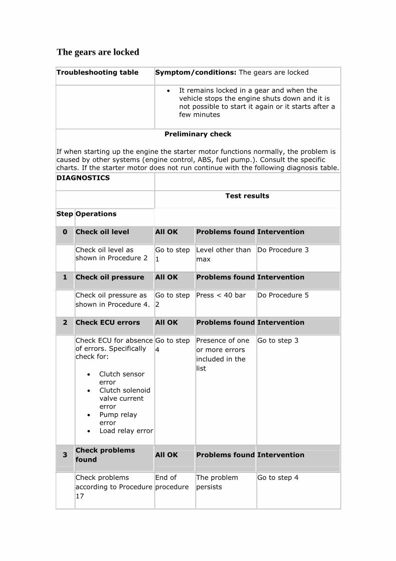
The gears are locked
Troubleshooting table Symptom/conditions: The gears are locked
It remains locked in a gear and when the
vehicle stops the engine shuts down and it is
not possible to start it again or it starts after a
few minutes
Preliminary check
If when starting up the engine the starter motor functions normally, the problem is
caused by other systems (engine control, ABS, fuel pump.). Consult the specific
charts. If the starter motor does not run continue with the following diagnosis table.
DIAGNOSTICS
Test results
Step Operations
0 Check oil level All OK Problems found Intervention
Check oil level as
shown in Procedure 2
Go to step
1
Level other than
max
Do Procedure 3
1 Check oil pressure All OK Problems found Intervention
Check oil pressure as
shown in Procedure 4.
Go to step
2
Press < 40 bar Do Procedure 5
2 Check ECU errors All OK Problems found Intervention
Check ECU for absence
of errors. Specifically check for:
Clutch sensor
error
Clutch solenoid
valve current
error
Pump relay
error Load relay error
Go to step
4
Presence of one
or more errors
included in the
list
Go to step 3
3 Check problems
found All OK Problems found Intervention
Check problems
according to Procedure
17
End of
procedure
The problem
persists
Go to step 4
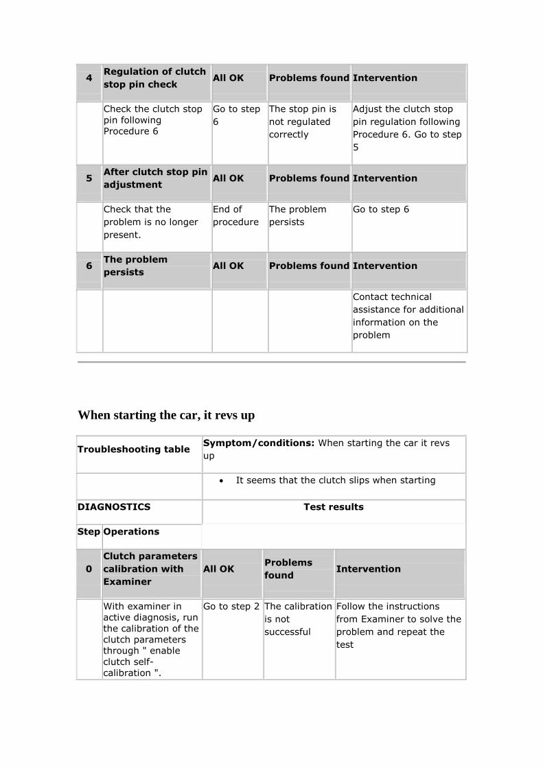
4 Regulation of clutch
stop pin check All OK Problems found Intervention
Check the clutch stop
pin following
Procedure 6
Go to step
6
The stop pin is
not regulated
correctly
Adjust the clutch stop
pin regulation following
Procedure 6. Go to step
5
5 After clutch stop pin
adjustment All OK Problems found Intervention
Check that the
problem is no longer
present.
End of
procedure
The problem
persists
Go to step 6
6 The problem
persists All OK Problems found Intervention
Contact technical
assistance for additional
information on the
problem
When starting the car, it revs up
Troubleshooting table Symptom/conditions: When starting the car it revs
up
It seems that the clutch slips when starting
DIAGNOSTICS Test results
Step Operations
0
Clutch parameters
calibration with
Examiner
All OK Problems
found Intervention
With examiner in
active diagnosis, run
the calibration of the
clutch parameters
through " enable
clutch self-
calibration ".
Go to step 2 The calibration
is not
successful
Follow the instructions
from Examiner to solve the
problem and repeat the
test
1
Regulation of
clutch stop pin
check
All OK Problems
found Intervention
Check the clutch
stop pin following
Procedure 6
Go to step 3 The stop pin is
not regulated
correctly
Adjust the clutch stop pin
regulation following
Procedure 6. Go to step 2
2 After clutch stop
pin adjustment All OK
Problems
found Intervention
Check that the
problem is no longer
present.
End of
procedure
The problem
persists
Go to step 3
4 The problem
persists All OK
Problems
found Intervention
Contact technical
assistance for additional
information on the problem
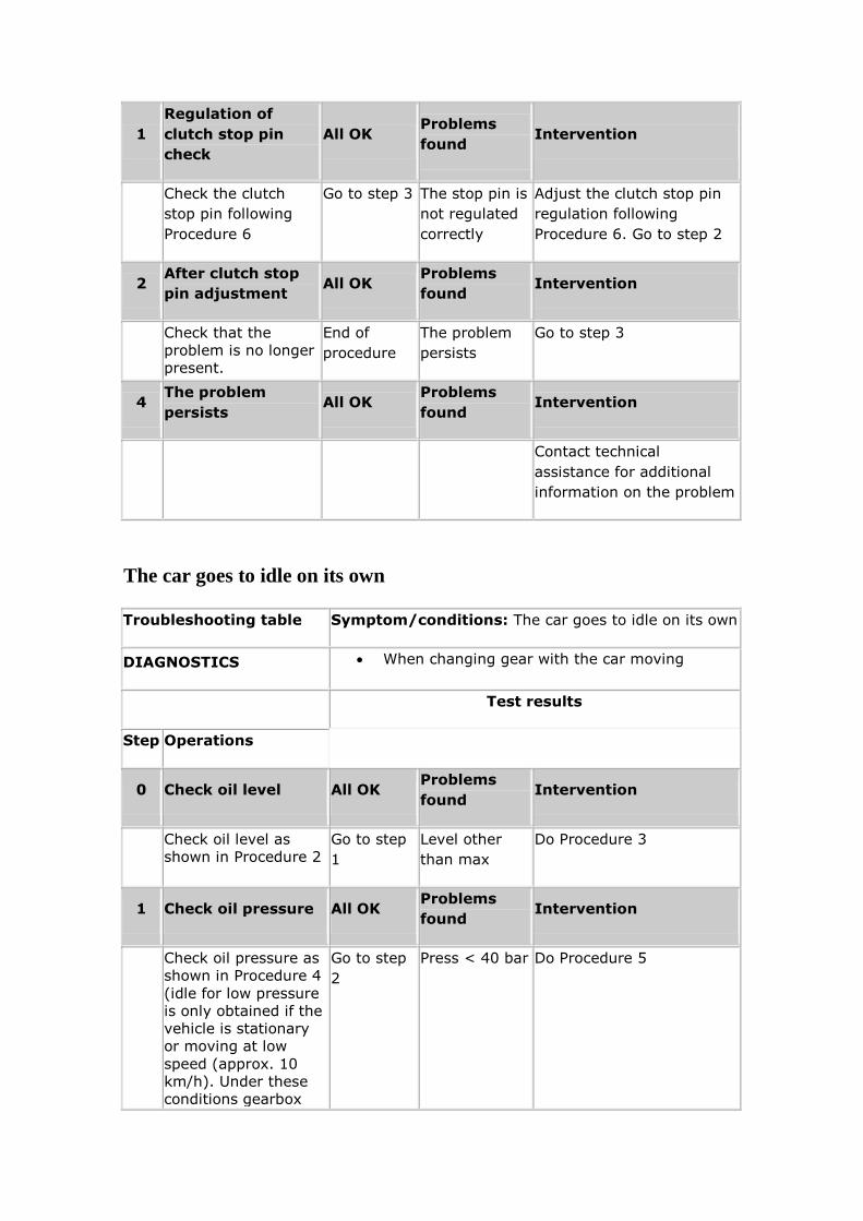
The car goes to idle on its own
Troubleshooting table Symptom/conditions: The car goes to idle on its own
DIAGNOSTICS When changing gear with the car moving
Test results
Step Operations
0 Check oil level All OK Problems
found Intervention
Check oil level as
shown in Procedure 2
Go to step
1
Level other
than max
Do Procedure 3
1 Check oil pressure All OK Problems
found Intervention
Check oil pressure as
shown in Procedure 4
(idle for low pressure
is only obtained if the
vehicle is stationary
or moving at low
speed (approx. 10
km/h). Under these
conditions gearbox
Go to step
2
Press < 40 bar Do Procedure 5
fault warning light
flashes on models
156 or the text
Selespeed Gearbox
Fault is displayed on
147 without any fault
being stored in the
control unit)
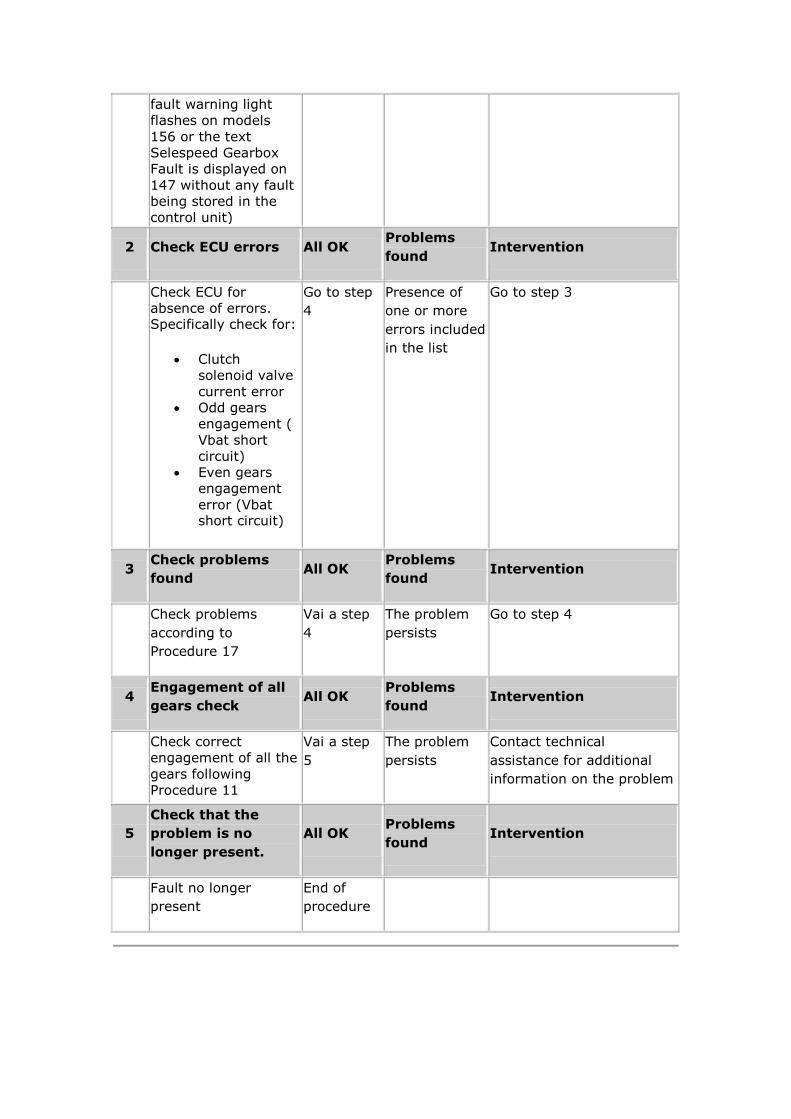
2 Check ECU errors All OK Problems
found Intervention
Check ECU for
absence of errors. Specifically check for:
Clutch
solenoid valve
current error
Odd gears
engagement (
Vbat short
circuit)
Even gears
engagement
error (Vbat short circuit)
Go to step
4
Presence of
one or more
errors included
in the list
Go to step 3
3 Check problems
found All OK
Problems
found Intervention
Check problems
according to
Procedure 17
Vai a step
4
The problem
persists
Go to step 4
4 Engagement of all
gears check All OK
Problems
found Intervention
Check correct
engagement of all the
gears following
Procedure 11
Vai a step
5
The problem
persists
Contact technical
assistance for additional
information on the problem
5
Check that the
problem is no
longer present.
All OK Problems
found Intervention
Fault no longer
present
End of
procedure
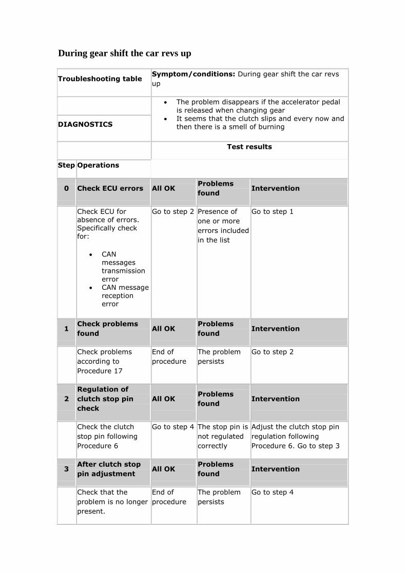
During gear shift the car revs up
Troubleshooting table Symptom/conditions: During gear shift the car revs
up
The problem disappears if the accelerator pedal
is released when changing gear
It seems that the clutch slips and every now and then there is a smell of burning DIAGNOSTICS
Test results
Step Operations
0 Check ECU errors All OK Problems
found Intervention
Check ECU for
absence of errors.
Specifically check
for:
CAN
messages
transmission
error
CAN message
reception error
Go to step 2 Presence of
one or more
errors included
in the list
Go to step 1
1 Check problems
found All OK
Problems
found Intervention
Check problems
according to
Procedure 17
End of
procedure
The problem
persists
Go to step 2
2
Regulation of
clutch stop pin
check
All OK Problems
found Intervention
Check the clutch
stop pin following
Procedure 6
Go to step 4 The stop pin is
not regulated
correctly
Adjust the clutch stop pin
regulation following
Procedure 6. Go to step 3
3 After clutch stop
pin adjustment All OK
Problems
found Intervention
Check that the
problem is no longer
present.
End of
procedure
The problem
persists
Go to step 4
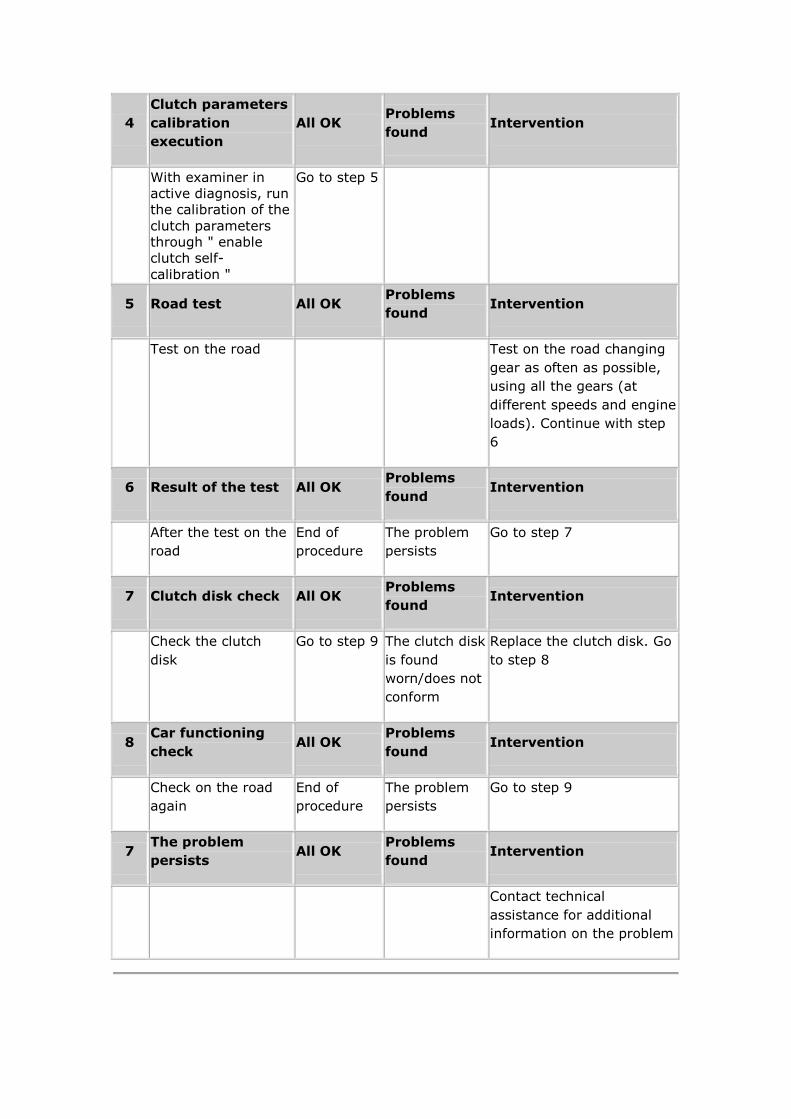
4
Clutch parameters
calibration
execution
All OK Problems
found Intervention
With examiner in
active diagnosis, run
the calibration of the
clutch parameters
through " enable
clutch self-
calibration "
Go to step 5
5 Road test All OK Problems
found Intervention
Test on the road Test on the road changing
gear as often as possible,
using all the gears (at
different speeds and engine
loads). Continue with step
6
6 Result of the test All OK Problems
found Intervention
After the test on the
road
End of
procedure
The problem
persists
Go to step 7
7 Clutch disk check All OK Problems
found Intervention
Check the clutch
disk
Go to step 9 The clutch disk
is found
worn/does not
conform
Replace the clutch disk. Go
to step 8
8 Car functioning
check All OK
Problems
found Intervention
Check on the road
again
End of
procedure
The problem
persists
Go to step 9
7 The problem
persists All OK
Problems
found Intervention
Contact technical
assistance for additional
information on the problem
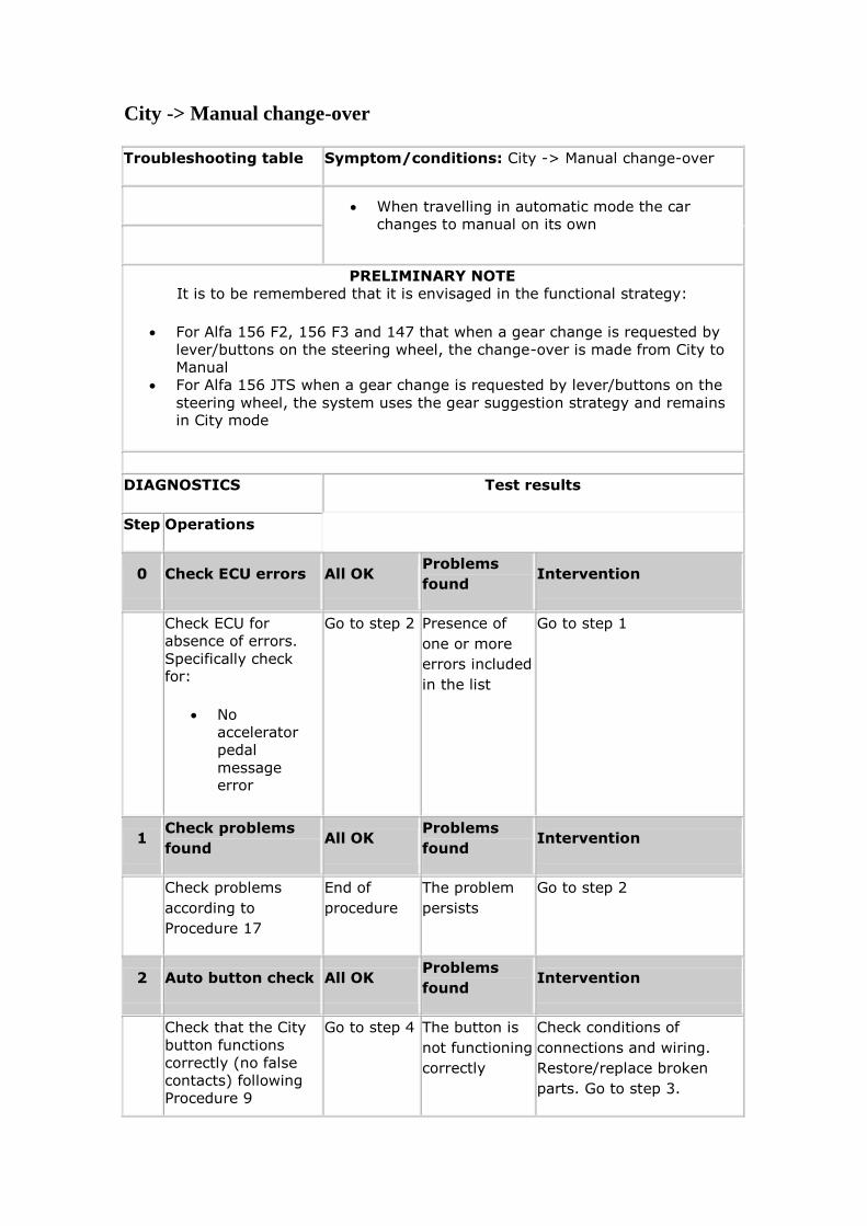
City -> Manual change-over
Troubleshooting table Symptom/conditions: City -> Manual change-over
When travelling in automatic mode the car
changes to manual on its own
PRELIMINARY NOTE
It is to be remembered that it is envisaged in the functional strategy:
For Alfa 156 F2, 156 F3 and 147 that when a gear change is requested by
lever/buttons on the steering wheel, the change-over is made from City to
Manual
For Alfa 156 JTS when a gear change is requested by lever/buttons on the
steering wheel, the system uses the gear suggestion strategy and remains in City mode
DIAGNOSTICS Test results
Step Operations
0 Check ECU errors All OK Problems
found Intervention
Check ECU for
absence of errors.
Specifically check for:
No
accelerator
pedal
message error
Go to step 2 Presence of
one or more
errors included
in the list
Go to step 1
1 Check problems
found All OK
Problems
found Intervention
Check problems
according to
Procedure 17
End of
procedure
The problem
persists
Go to step 2
2 Auto button check All OK Problems
found Intervention
Check that the City
button functions
correctly (no false
contacts) following
Procedure 9
Go to step 4 The button is
not functioning
correctly
Check conditions of
connections and wiring.
Restore/replace broken
parts. Go to step 3.
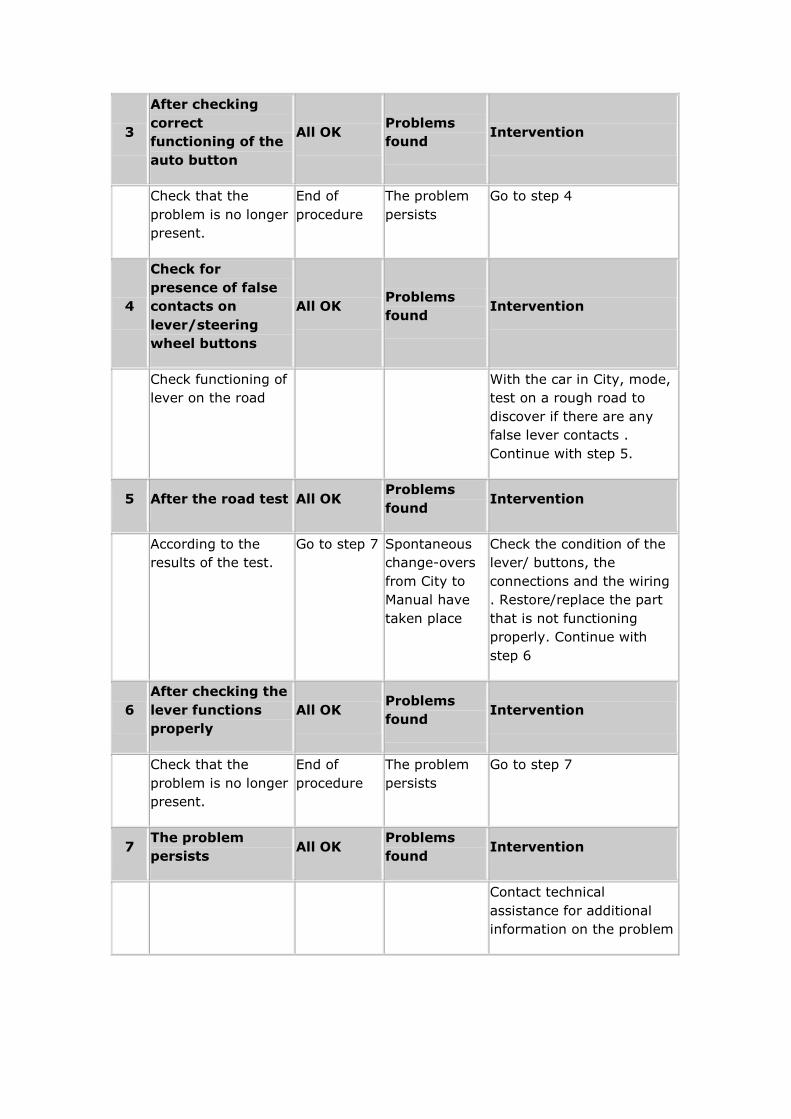
3
After checking
correct
functioning of the
auto button
All OK Problems
found Intervention
Check that the
problem is no longer
present.
End of
procedure
The problem
persists
Go to step 4
4
Check for
presence of false
contacts on
lever/steering
wheel buttons
All OK Problems
found Intervention
Check functioning of
lever on the road
With the car in City, mode,
test on a rough road to
discover if there are any
false lever contacts .
Continue with step 5.
5 After the road test All OK Problems
found Intervention
According to the
results of the test.
Go to step 7 Spontaneous
change-overs
from City to
Manual have
taken place
Check the condition of the
lever/ buttons, the
connections and the wiring
. Restore/replace the part
that is not functioning
properly. Continue with
step 6
6
After checking the
lever functions
properly
All OK Problems
found Intervention
Check that the
problem is no longer
present.
End of
procedure
The problem
persists
Go to step 7
7 The problem
persists All OK
Problems
found Intervention
Contact technical
assistance for additional
information on the problem
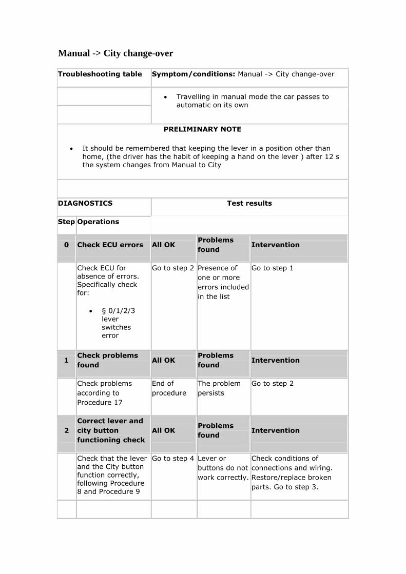
Manual -> City change-over
Troubleshooting table Symptom/conditions: Manual -> City change-over
Travelling in manual mode the car passes to
automatic on its own
PRELIMINARY NOTE
It should be remembered that keeping the lever in a position other than
home, (the driver has the habit of keeping a hand on the lever ) after 12 s the system changes from Manual to City
DIAGNOSTICS Test results
Step Operations
0 Check ECU errors All OK Problems
found Intervention
Check ECU for
absence of errors.
Specifically check
for:
§ 0/1/2/3
lever
switches error
Go to step 2 Presence of
one or more
errors included
in the list
Go to step 1
1 Check problems
found All OK
Problems
found Intervention
Check problems
according to
Procedure 17
End of
procedure
The problem
persists
Go to step 2
2
Correct lever and
city button
functioning check
All OK Problems
found Intervention
Check that the lever
and the City button
function correctly,
following Procedure
8 and Procedure 9
Go to step 4 Lever or
buttons do not
work correctly.
Check conditions of
connections and wiring.
Restore/replace broken
parts. Go to step 3.
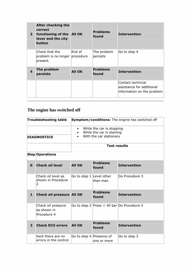
3
After checking the
correct
functioning of the
lever and the city
button
All OK Problems
found Intervention
Check that the
problem is no longer
present.
End of
procedure
The problem
persists
Go to step 4
4 The problem
persists All OK
Problems
found Intervention
Contact technical
assistance for additional
information on the problem
The engine has switched off
Troubleshooting table Symptom/conditions: The engine has switched off
While the car is stopping
While the car is starting
With the car stationary DIAGNOSTICS
Test results
Step Operations
0 Check oil level All OK Problems
found Intervention
Check oil level as
shown in Procedure
2
Go to step 1 Level other
than max
Do Procedure 3
1 Check oil pressure All OK Problems
found Intervention
Check oil pressure
as shown in
Procedure 4
Go to step 2 Press < 40 bar Do Procedure 5
2 Check ECU errors All OK Problems
found Intervention
heck there are no
errors in the control
Go to step 4 Presence of
one or more
Go to step 3
unit. In particular:
Clutch sensor
error *
Clutch
solenoid
valve current
error *
Load relay
error*
Odd gears
engagement
( Vbat short
circuit)*
Even gears
engagement
error (Vbat
short
circuit)*
errors included
in the list
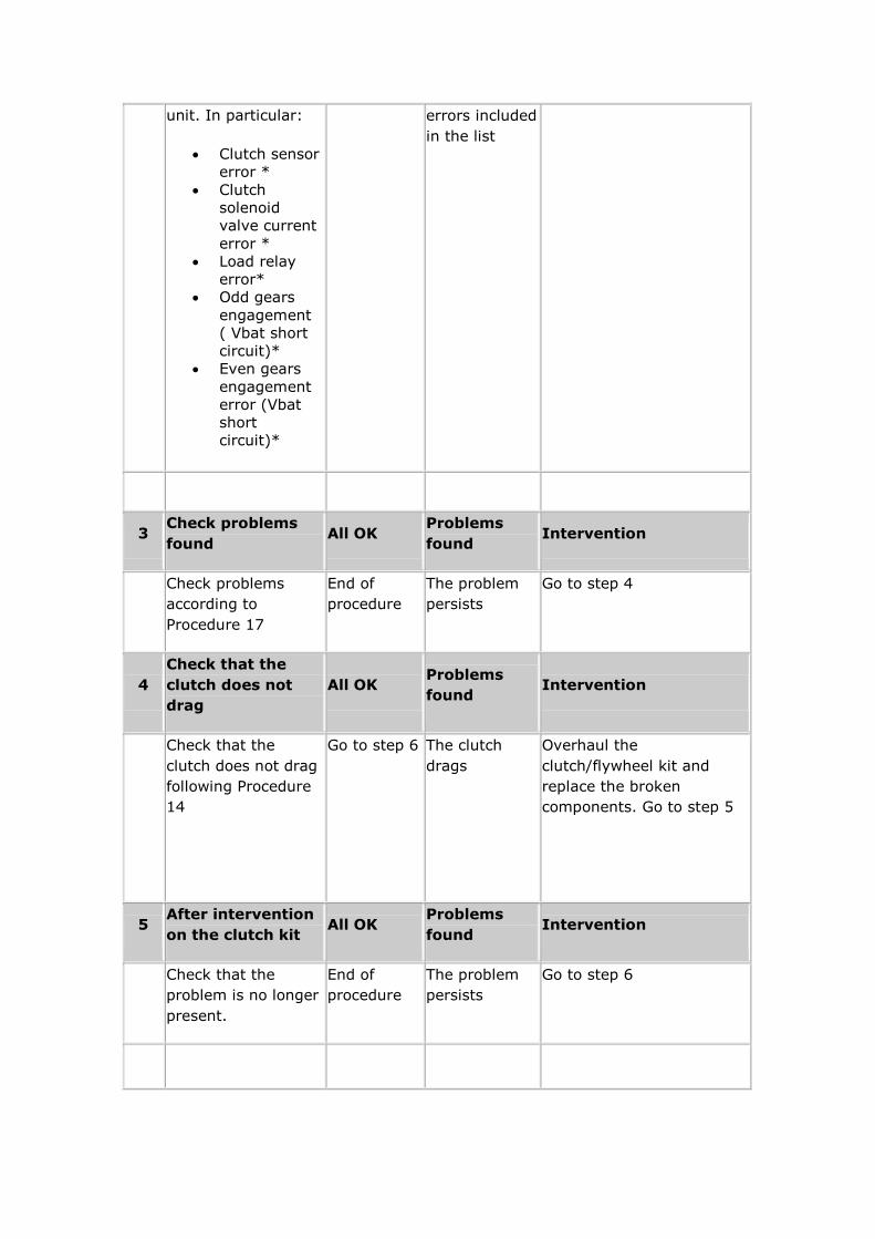
3 Check problems
found All OK
Problems
found Intervention
Check problems
according to
Procedure 17
End of
procedure
The problem
persists
Go to step 4
4
Check that the
clutch does not
drag
All OK Problems
found Intervention
Check that the
clutch does not drag
following Procedure
14
Go to step 6 The clutch
drags
Overhaul the
clutch/flywheel kit and
replace the broken
components. Go to step 5
5 After intervention
on the clutch kit All OK
Problems
found Intervention
Check that the
problem is no longer
present.
End of
procedure
The problem
persists
Go to step 6
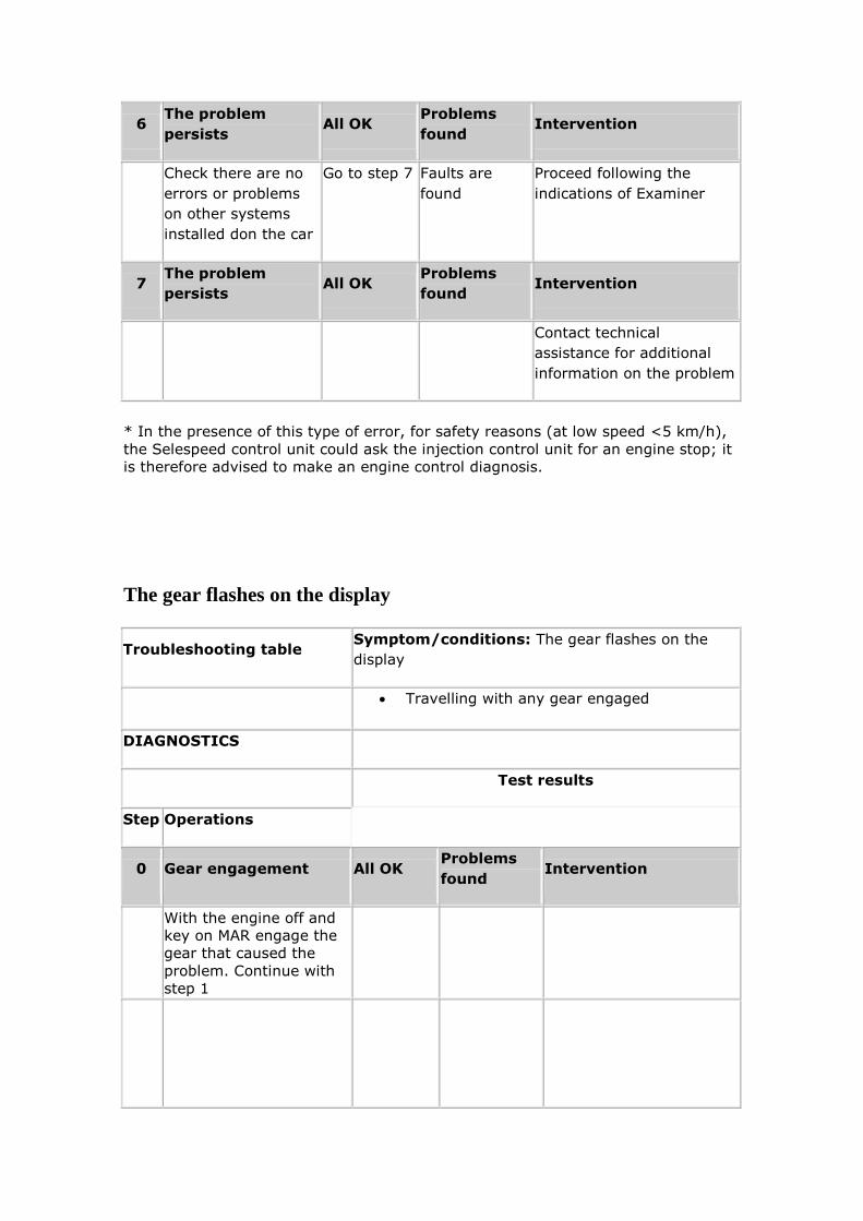
6 The problem
persists All OK
Problems
found Intervention
Check there are no
errors or problems
on other systems
installed don the car
Go to step 7 Faults are
found
Proceed following the
indications of Examiner
7 The problem
persists All OK
Problems
found Intervention
Contact technical
assistance for additional
information on the problem
* In the presence of this type of error, for safety reasons (at low speed <5 km/h),
the Selespeed control unit could ask the injection control unit for an engine stop; it
is therefore advised to make an engine control diagnosis.
The gear flashes on the display
Troubleshooting table Symptom/conditions: The gear flashes on the
display
Travelling with any gear engaged
DIAGNOSTICS
Test results
Step Operations
0 Gear engagement All OK Problems
found Intervention
With the engine off and
key on MAR engage the
gear that caused the
problem. Continue with
step 1
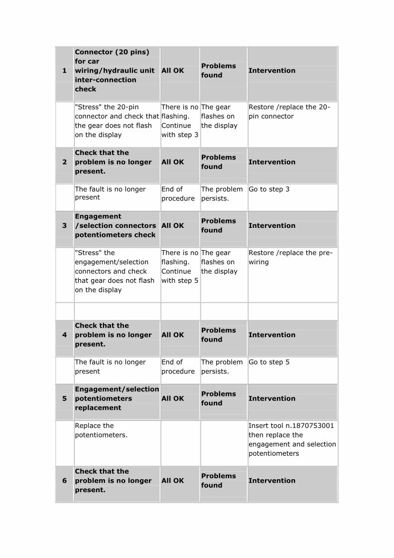
1
Connector (20 pins)
for car
wiring/hydraulic unit
inter-connection
check
All OK Problems
found Intervention
"Stress" the 20-pin
connector and check that
the gear does not flash
on the display
There is no
flashing.
Continue
with step 3
The gear
flashes on
the display
Restore /replace the 20-
pin connector
2
Check that the
problem is no longer
present.
All OK Problems
found Intervention
The fault is no longer
present
End of
procedure
The problem
persists.
Go to step 3
3
Engagement
/selection connectors
potentiometers check
All OK Problems
found Intervention
"Stress" the
engagement/selection
connectors and check
that gear does not flash
on the display
There is no
flashing.
Continue
with step 5
The gear
flashes on
the display
Restore /replace the pre-
wiring
4
Check that the
problem is no longer
present.
All OK Problems
found Intervention
The fault is no longer
present
End of
procedure
The problem
persists.
Go to step 5
5
Engagement/selection
potentiometers
replacement
All OK Problems
found Intervention
Replace the
potentiometers.
Insert tool n.1870753001
then replace the
engagement and selection
potentiometers
6
Check that the
problem is no longer
present.
All OK Problems
found Intervention

The fault is no longer
present
End of
procedure
The problem
persists.
Go to step 7
7 The problem persists All OK Problems
found Intervention
Contact technical
assistance for additional
information on the
problem
PROCEDURES
Procedure 2.
Oil level check
1. Wait for the electric pump to switch off (The pump activates when the door on
the driver's side is opened and automatically switches off after a maximum time of 30 seconds).
2. Set the ignition key on MAR.
3. Make several gear shifts with the engine off so as to activate the electric pump.
4. Immediately after the electric pump switches off, check the hydraulic unit oil level with the dip-stick under the cap of the tank.
5. If the oil level is under the Max marking, top up ; if it is over, bring it down to Max level.
Procedure 3.
Oil leaks check
1. After checking the oil level (see procedure 2), make a note of how much is
needed for topping up.
2. Make a visual check on the pipes, electric pump, tank, hydraulic unit,
engagement/selection actuator, clutch stop pin (removing the casing that covers it)
while making 50 gear shifts from 1st to 5th/R and from 5th/R to 1st ( at a
frequency of 1 gear change every 3-4 s).
3. If leaks are found, replace/repair the parts involved, top up the oil and start
again from step 1.
4. If there are no leaks:
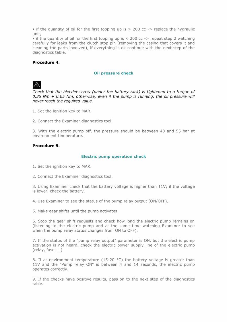
• if the quantity of oil for the first topping up is > 200 cc -> replace the hydraulic
unit,
• if the quantity of oil for the first topping up is < 200 cc -> repeat step 2 watching
carefully for leaks from the clutch stop pin (removing the casing that covers it and
cleaning the parts involved), if everything is ok continue with the next step of the diagnostics table.
Procedure 4.
Oil pressure check
Check that the bleeder screw (under the battery rack) is tightened to a torque of
0.35 Nm + 0.05 Nm, otherwise, even if the pump is running, the oil pressure will never reach the required value.
1. Set the ignition key to MAR.
2. Connect the Examiner diagnostics tool.
3. With the electric pump off, the pressure should be between 40 and 55 bar at environment temperature.
Procedure 5.
Electric pump operation check
1. Set the ignition key to MAR.
2. Connect the Examiner diagnostics tool.
3. Using Examiner check that the battery voltage is higher than 11V; if the voltage is lower, check the battery.
4. Use Examiner to see the status of the pump relay output (ON/OFF).
5. Make gear shifts until the pump activates.
6. Stop the gear shift requests and check how long the electric pump remains on
(listening to the electric pump and at the same time watching Examiner to see
when the pump relay status changes from ON to OFF).
7. If the status of the "pump relay output" parameter is ON, but the electric pump
activation is not heard, check the electric power supply line of the electric pump (relay, fuse……)
8. If at environment temperature (15-20 °C) the battery voltage is greater than
11V and the "Pump relay ON" is between 4 and 14 seconds, the electric pump
operates correctly.
9. If the checks have positive results, pass on to the next step of the diagnostics table.

NOTE: Repeat the test several times to make sure.
Procedure 6.
Clutch stop pin adjustment check
1. Set the ignition key to MAR.
2. Connect the Examiner diagnostics tool.
3. Check that the clutch position is between 28 and 28.5 mm; if it is not, continue
with the next step.
4. Loosen the lock nut (1c in Fig.16) and adjust the stop pin so that the clutch position value read on Examiner is between 28 and 28.5 mm.
5. Tighten the lock nut to a torque of 0.6 ± 0.05 Nm and measure again.
Procedure 7.
Brake pedal switch check
1. Set the ignition key to MAR.Connect the Examiner diagnostics tool and select
the input status display (ON/OFF) regarding the switch on the brake pedal.
2. Press the brake pedal and check that the displayed value changes (from released to pressed and vice-versa).
3. If this status change does not take place check the brake pedal switch, its fastening, its position and its wiring.
Procedure 8.
Buttons on steering wheel and gear lever check
1. Set the ignition key to MAR.
2. Connect the Examiner diagnostics tool and select the "LEVERS STATUS" display
in parameters environment.
3. Make all the selections possible with the buttons on the steering wheel and the
gear lever (one at a time) checking the correct status change on Examiner; the list
of the selections to be made is the following:
• Lever Up (+) (forward)
• Lever Down (-) (backward)
• RH button Up on steering wheel (+)
• LH button Down on steering wheel (-)

• Lever on idle (N)
• Lever on Reverse (R)
• Buttons and lever released
4. If the status displayed is not correct, check the wiring and gearshift
buttons/lever.
Procedure 9.
City button check (automatic operation selection)
1. Set the ignition key to MAR.
2. Connect the Examiner diagnostics tool and select the display of the input states (ON/OFF) for the auto button.
3. Press and release the automatic operation selection button at the base of the gear lever (this check is to be made with the engine running).
4. Check on Examiner that the status has changed.
5. Start the engine and check that when the button is pressed "CITY" is seen on the display.
6. If the status does not change (step 4) and/or "CITY" is not displayed (step 5.),
check the button and the wiring.
Procedure 11.
Correct engagement of all the gears with the gear shift lever and the
engine off check
1. With the ignition key on MAR and the brake pedal pressed, engage all the gears with the gear lever and check on the display that they engage properly
Lever
Display
1
2
3
4
5
R
1. If all the gears engage and are shown correctly on the display the procedure ends here.
Procedure 14.
Clutch drag check*
1. Connect the Examiner diagnostics tool .
2. Start the car and put the gear to idle.
3. With the engine running at minimum, read the value of the clutch disk speed
parameter
4. If the clutch disk speed is over zero there is a clutch drag condition
5. Calibrate the clutch parameters in active diagnostics through "enable clutch self-calibration ".
6. Repeat from step 2 to step 4. If the fault no longer occurs: continue from step 7.
7. If there is no clutch drag, warm the engine and the clutch by a series of take-offs (with the accelerator pressed down over half of its stroke)
8. Repeat steps 1 to 4
9. If the situation of step 4 occurs, there is a clutch drag condition and therefore the clutch mechanism needs to be replaced; otherwise there is no clutch drag.
* Note that clutch drag often occurs with a hot engine
Procedure 17.
What to do according to the error on the Selespeed control unit
• CAN network error:
• Check:
• The network sees all the control units (n.b.: pay attention because any control
unit connected to the CAN network could cause faults in network operation). If one of the control units does not dialogue, recover/replace that control unit.
• Condition of the connections and continuity of the wiring regarding the CAN line.
It is better not to just make a visual analysis of the connection, but to test putting
it under mechanical stress (pull the wires, twist them, and check that the pins are firm); if a fault is found, restore/replace the wiring.
• Engine speed (from wire):
• check the correct connection between engine control unit and Selespeed control
unit, since this signal is sent by the engine control unit through a special wire. If a
fault is found restore/replace the part involved.

• 1st/2nd gear range selection solenoid valve:
• Run the solenoid valve active diagnostics. If the test does not give satisfactory
results, pass to the next step
• Check the condition of the connections and continuity of the wiring. If a fault is found, restore/replace the wiring.
• Run the solenoid valve active diagnostics again. If the test does not give satisfactory results replace the solenoid valve and check the functioning.
• 5th/R gear range selection solenoid valve
• Run the solenoid valve active diagnostics. If the test does not give satisfactory results, pass to the next step
• Check the condition of the connections and continuity of the wiring. If a fault is found, restore/replace the wiring.
• Run the solenoid valve active diagnostics again. If the test does not give
satisfactory results replace the solenoid valve and check the functioning.
• Clutch solenoid valve current error:
• Check the condition of the connections and continuity of the wiring. If a fault is found, restore/replace the wiring.
• Replace the solenoid valve and check the functioning by making a gear shift.
• Clutch sensor:
• Check the condition of the connections and continuity of the wiring. If a fault is found, restore/replace the wiring.
• Replace the clutch potentiometer and check the functioning by making a gear shift.
• Odd or even gears engagement (engagement solenoid valves)
• Run the solenoid valve active diagnostics. If the test does not give satisfactory results, pass to the next step
• Check the condition of the connections and continuity of the wiring. If a fault is
found, restore/replace the wiring.
• Run the solenoid valve active again. If the test does not give satisfactory results replace the solenoid valve and check the functioning.
• Control unit earth error
• Check the tightness of the earth connections on the body and on the engine.
• Check the condition of the connections and continuity of the wiring. If a fault is found, restore/replace the wiring.

• Charging relay error*
• Check the condition of the battery
• Check the condition of the connections and continuity of the wiring. Make a
careful check on the items that supply the power to the control unit (wiring, fuses, relay etc.). If a fault is found, restore/replace the wiring.
• Lever switches 0/1/2/3 error
• Connect the Examiner diagnostics tool and select "LEVER STATUS" in parameters environment.
• Make all the selections possible with the buttons on the steering wheel and the
gear lever (one at a time) checking the correct status change on Examiner; the list
of the selections to be made is the following:
• Lever Up (+) (forward)
• Lever Down (-) (backward)
• Lever on idle (N)
• Lever on Reverse (R)
• Lever released
• If the status displayed is not correct, check the connections, the wiring continuity and the gear shift lever.
• Lever switch error (any of the four, or auto button)
Lever check
• Connect the Examiner diagnostics tool and select the "LEVERS STATUS" display in
parameters environment.
• Make all the selections possible with the buttons on the steering wheel and the
gear lever (one at a time) checking the correct status change on Examiner; the list of the selections to be made is the following:
• Lever Up (+) (forward)
• Lever Down (-) (backward)
• Lever on idle (N)
• Lever on Reverse (R)
• Lever released
• If the status displayed is not correct, check the connections, the wiring continuity and the gear shift lever.

• Auto button check
• Select the state of inputs display (ON/OFF) relating to the auto button.
• Press and release the automatic operation selection button at the base of the gear
shift lever.
• Check on Examiner that the change of status has taken place.
• Start the engine and check that when the button is pressed, "AUTO" is shown on
the display.
• If the change of status does not take place (step 4) and/or "AUTO" is not displayed (step 5.), check the button and the wiring
N.B. there have been cases where the auto button remains stuck: this can cause malfunctioning of the lever.
• Engagement sensor. When this error is present, the gear change is slower than usual due to the system operating in recovery.
• Check the condition of the connections and continuity of the wiring. If a fault is
found, restore/replace the wiring.
• Replace the engagement potentiometer ** and check the correct reading of the position, making a series of gear changes
• Selection sensor. When this error is present, the gear change is slower than usual due to the system operating in recovery.
• Check the condition of the connections and continuity of the wiring. If a fault is found, restore/replace the wiring.
• Replace the selection potentiometer and check the correct reading of the position,
making a series of gear changes.
• Clutch disk speed (this signal is read by the sensor that reads the speed
of the primary shaft***)
• Check the condition of the connections and continuity of the wiring. If a fault is found, restore/replace the wiring.
• Replace the clutch disk speed sensor (see components r/r general procedure) and check the correct reading of the position, making a series of gear changes.
• Car speed.
Only for Alfa 156 Selespeed: N.B. The car speed signal is supplied by the
Instrument Panel on board to the Selespeed control unit; therefore any signal
omission/fault on the panel will also result on the Selespeed System.Proceed as
follows:
• Check that the car speed signal arrives continually to the Panel on board.

• If the signal does not arrive continuously:
• Proceed following the instructions in the Service Handbook
• If the signal arrives continuously:
• Check the condition of the connections and continuity of the line wiring, especially
between the control units signalled with an error. If a fault is found, restore/replace the wiring
Only for Alfa 147 Selespeed: N.B. The car speed signal reaches the Selespeed
control unit through the CAN line from the ABS control unit, therefore any signal
omission/fault on the ABS control unit will also result on the Selespeed System. Proceed as follows:
• Check whether there are any faults in the ABS control unit and/or the engine control unit that justifies the omission of the car speed signal.
• If no faults are found:
• Use the EXAMINER diagnostics tool to check for dialogue problems on the CAN
line
• No accelerator pedal information. The signal is received by the Selespeed control unit through the CAN line:
• On Examiner select CAN network information and check if there is the presence of control unit error
• Check the condition of the connections and continuity of the line wiring, especially
between the control units signalled with an error. If a fault is found, restore/replace
the wiring.
• Brake switch. The signal is received by the Selespeed control unit through the
CAN line and through a wire:
• Check the condition of the brake switch.
1. Bring the ignition key to MAR.
2. Connect the Examiner diagnostics tool and select the inputs status display (ON/OFF) for the switch on the brake pedal.
3. Press the brake pedal and check that the displayed value changes (from released to pressed and vice-versa).
4. If there is no status change check the switch on the brake pedal, its fastening, its position, the condition of the connections and the wiring.
• If a fault is found, restore/replace the components/wiring

• Pump relay error
• check the condition of the connections and continuity of the wiring. Make a careful
check on the items that supply power to the electric pump (fuses, relay etc.). If a
fault is found, restore/replace the wiring. There have been cases where the "fastom" housed in the relay holder socket have pulled out.
• Accumulator oil discharge error:
• replace the accumulator
• Start enable relay error
• The Selespeed control unit supplies the earth for the start relay block; if a short
circuit to the battery or an open circuit is diagnosed, the engine cannot start; if
instead a short circuit to earth is found the engine can be started without the
enable from the Selespeed control unit. In any case the problem arises from the
wiring or from systems that enable the start downstream of the Selespeed control
unit. Check the condition of the connections and the continuity of the wiring downstream of the Selespeed control unit.
• Check the condition of the brake switch.
1. Bring the ignition key to MAR.
2. Connect the Examiner diagnostics tool and select the inputs status display
(ON/OFF) for the switch on the brake pedal.
3. Press the brake pedal and check that the displayed value changes.
4. If there is no status change check the switch on the brake pedal, its fastening,
its position, the condition of the connections and the wiring.
• If a fault is found, restore/replace the components/wiring.
* This error is connected to a control unit power supply problem and not to the
control unit itself** It is a good practice to insert tool n°1870753001 before
removing the hydraulic unit potentiometer*** This sensor is positioned on the
gearbox to the right of the reverse lights sensor
Procedure 18.
Check the functioning of the clutch disk speed sensor with road test
1. Connect the Examiner diagnostics tool
2. In parameters environment view:
• Engine revs
• Clutch disk speed
3. Make a road test at a steady speed without changing gear (V approx. 30 km/h).

4. While driving watch the two selected parameters
5. Check that there are no significant fluctuations/ differences on the clutch speed
sensor in relation to the engine revs.
156 2.0 JTS Selespeed Schematics
Component locations
Wiring diagram 1

Wiring diagram 2
From 2005 Paul Denyer website