aluminium mig welding guide.pdf
TRANSCRIPT

8/10/2019 Aluminium Mig Welding Guide.pdf
http://slidepdf.com/reader/full/aluminium-mig-welding-guidepdf 1/28
8/10/2019 Aluminium Mig Welding Guide.pdf
http://slidepdf.com/reader/full/aluminium-mig-welding-guidepdf 2/28
SUPERGLAZE ALUMINUM WIRE TECHNICAL GUIDE
CONTENTS
I. THE EXTRAORDINARY ADVANTAGES OF SUPERGLAZE . . . . . . . . . . . . . . . . . . . . . . . . .3
II. EFFECTS OF ALLOYING ELEMENTS . . . . . . . . . . . . . . . . . . . . . . . . . . . . . . . . . . . . . .4-10
Metallurgy . . . . . . . . . . . . . . . . . . . . . . . . . . . . . . . . . . . . . . . . . . . . . . . . . . . . . . . . . . . .4
Alloying Elements . . . . . . . . . . . . . . . . . . . . . . . . . . . . . . . . . . . . . . . . . . . . . . . . . . . .4-5Temper Designations . . . . . . . . . . . . . . . . . . . . . . . . . . . . . . . . . . . . . . . . . . . . . . . . . . .5
Chemical Composition of SuperGlaze MIG Wires . . . . . . . . . . . . . . . . . . . . . . . . . . . .6
Electrode Description and Selections . . . . . . . . . . . . . . . . . . . . . . . . . . . . . . . . . . . . . .7
Filler Alloy Selection . . . . . . . . . . . . . . . . . . . . . . . . . . . . . . . . . . . . . . . . . . . . . . . . . . . .7
Filler Metal Guide . . . . . . . . . . . . . . . . . . . . . . . . . . . . . . . . . . . . . . . . . . . . . . . . . . . . . .8
How Alloys Effect Mechanical Properties . . . . . . . . . . . . . . . . . . . . . . . . . . . . . . . .9-10
III. HOW PHYSICAL PROPERTIES EFFECT WELDING PROCEDURES . . . . . . . . . . . . .10-13
Electrical Conductivity . . . . . . . . . . . . . . . . . . . . . . . . . . . . . . . . . . . . . . . . . . . . . .10-11
How Alloys Effect Penetration . . . . . . . . . . . . . . . . . . . . . . . . . . . . . . . . . . . . . . . . . . .11
CTTWD vs. Arc Length . . . . . . . . . . . . . . . . . . . . . . . . . . . . . . . . . . . . . . . . . . . . . . . . .12Causes and Curves for Weld Porosity . . . . . . . . . . . . . . . . . . . . . . . . . . . . . . . . . .12-13
IV. RECOMMENDED PROCEDURES . . . . . . . . . . . . . . . . . . . . . . . . . . . . . . . . . . . . . . . .14-16
Cleaning of Base Material and Wire . . . . . . . . . . . . . . . . . . . . . . . . . . . . . . . . . . . . . .14
Welding Parameters . . . . . . . . . . . . . . . . . . . . . . . . . . . . . . . . . . . . . . . . . . . . . . . . . . .14
Joint Geometry . . . . . . . . . . . . . . . . . . . . . . . . . . . . . . . . . . . . . . . . . . . . . . . . . . . . . . .14
Typical Joint Geometries Aluminum MIG Welding . . . . . . . . . . . . . . . . . . . . . . . . . . .15
Typical Procedures for Aluminum MIG Welding . . . . . . . . . . . . . . . . . . . . . . . . . . . . .16
V. PULSING AND WAVEFORM MANIPULATION . . . . . . . . . . . . . . . . . . . . . . . . . . . . . . .17-18
Evolution of Power Supplies for GMAW of Aluminum . . . . . . . . . . . . . . . . . . . . . . . .17
Anatomy of a Waveform . . . . . . . . . . . . . . . . . . . . . . . . . . . . . . . . . . . . . . . . . . . . . . . .18
Process Optimization via Manipulating Waveform . . . . . . . . . . . . . . . . . . . . . . . . . . .18
VI. TROUBLESHOOTING . . . . . . . . . . . . . . . . . . . . . . . . . . . . . . . . . . . . . . . . . . . . . . . . . .19-20
VII. REFERENCES . . . . . . . . . . . . . . . . . . . . . . . . . . . . . . . . . . . . . . . . . . . . . . . . . . . . . . . . . . .20
ARC WELDING SAFETY REGULATIONS . . . . . . . . . . . . . . . . . . . . . . . . . . . . . . . . . . .21-24
-2-
8/10/2019 Aluminium Mig Welding Guide.pdf
http://slidepdf.com/reader/full/aluminium-mig-welding-guidepdf 3/28
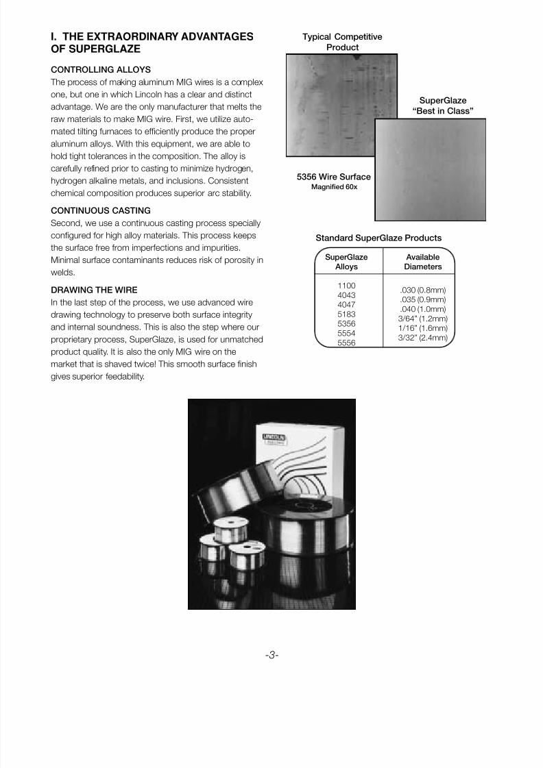
SuperGlaze Available
Alloys Diameters
1100.030 (0.8mm)
4043.035 (0.9mm)
4047.040 (1.0mm)
51833/64” (1.2mm)
53561/16” (1.6mm)
55543/32” (2.4mm)
5556
-3-
I. THE EXTRAORDINARY ADVANTAGESOF SUPERGLAZE
CONTROLLING ALLOYS
The process of making aluminum MIG wires is a complex
one, but one in which Lincoln has a clear and distinct
advantage. We are the only manufacturer that melts the
raw materials to make MIG wire. First, we utilize auto-
mated tilting furnaces to efficiently produce the properaluminum alloys. With this equipment, we are able to
hold tight tolerances in the composition. The alloy is
carefully refined prior to casting to minimize hydrogen,
hydrogen alkaline metals, and inclusions. Consistent
chemical composition produces superior arc stability.
CONTINUOUS CASTING
Second, we use a continuous casting process specially
configured for high alloy materials. This process keeps
the surface free from imperfections and impurities.
Minimal surface contaminants reduces risk of porosity in
welds.
DRAWING THE WIRE
In the last step of the process, we use advanced wire
drawing technology to preserve both surface integrity
and internal soundness. This is also the step where our
proprietary process, SuperGlaze, is used for unmatched
product quality. It is also the only MIG wire on the
market that is shaved twice! This smooth surface finish
gives superior feedability.
5356 Wire SurfaceMagnified 60x
SuperGlaze
“Best in Class”
Typical Competitive
Product
Standard SuperGlaze Products
8/10/2019 Aluminium Mig Welding Guide.pdf
http://slidepdf.com/reader/full/aluminium-mig-welding-guidepdf 4/28
II. EFFECTS OF ALLOYING ELEMENTS
METALLURGY
To understand aluminum, we must first understand
some basics about aluminum metallurgy. Aluminum can
be alloyed with a number of different elements, both
primary and secondary, to provide improved strength,
corrosion resistance and/or general weldability.
The primary elements that alloy with aluminum are
copper, silicon, manganese, magnesium and zinc. It isimportant to note that these alloys fall into two classes:
heat-treatable or nonheat-treatable.
Heat-treatable alloys are those that can be heat-treated
to increase their mechanical properties. To heat-treat an
alloy means heating it at a high temperature, putting the
alloying elements into solid solution and then cooling it
at a rate which will produce a supersaturated solution.
The next step in the process is to maintain it at a lower
temperature long enough to allow a controlled amount
of precipitation of the alloying elements.
With the nonheat-treatable alloys it is possible toincrease strength only through cold working or strain
hardening. To do this, a mechanical deformation must
occur in the metal structure, resulting in increased
resistance to strain, producing higher strength and
lower ductility.
Two designations have been developed to identify
aluminum alloys. The most commonly used alloys are
normally identified using wrought alloy designations.
This designation is a four digit number where the first
digit indicates the principal alloying element or elements.
If the second digit is not zero, then the original registered
alloy has been modified in some way. The third and
fourth digits are arbitrary numbers that identify the
specific alloy, as shown in Table 1 on page 6. The
exception to this is with the 1XXX series alloys that are
almost pure aluminum. For this series, these digits
indicate the degree of purity above 99.00%. For
example, 1080 is 99.80% pure aluminum.
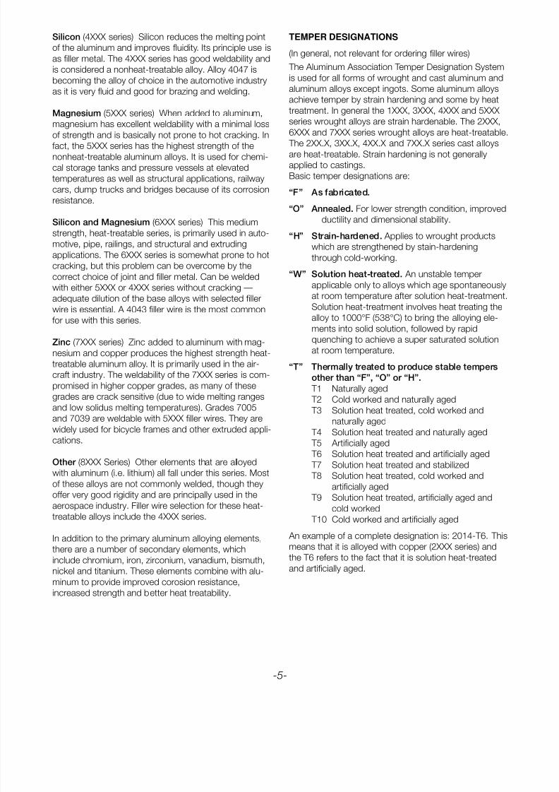
For cast alloy designations, a three digit number plus
one decimal is used to designate each cast alloy. The
first digit indicates the principal alloying element. The
cast alloy designations lack the modification digit of the
wrought designations. Instead modifications are indicat-
ed by a prefix letter (A,B,C, etc.). The second and third
digits form the arbitrary number identifying the specific
alloy. The decimal indicates whether the alloy composi-
tion is for the final casting (.0), or for the ingot (.1 or .2
depending on purity limits).
-4-
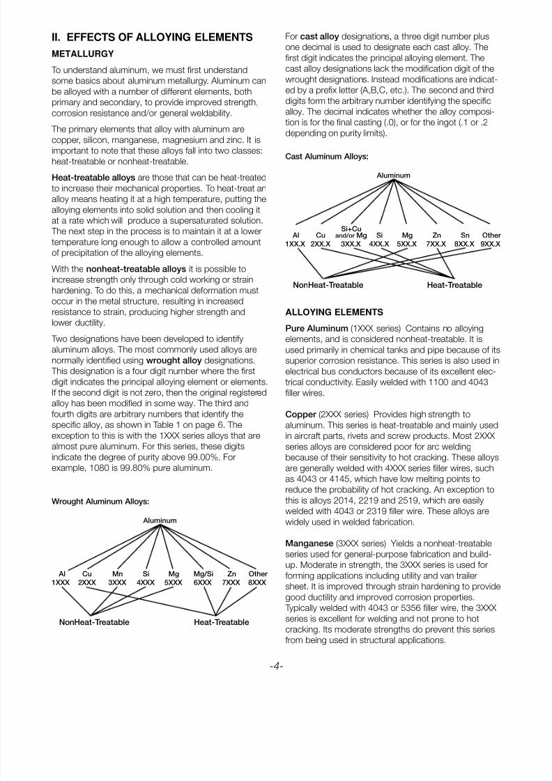
Wrought Aluminum Alloys:
Aluminum
Al Cu Mn Si Mg Mg/Si Zn Other
1XXX 2XXX 3XXX 4XXX 5XXX 6XXX 7XXX 8XXX
NonHeat-Treatable Heat-Treatable
Cast Aluminum Alloys:
Aluminum
Si+Cu Al Cu and/or Mg Si Mg Zn Sn Other
1XX.X 2XX.X 3XX.X 4XX.X 5XX.X 7XX.X 8XX.X 9XX.X
NonHeat-Treatable Heat-Treatable
ALLOYING ELEMENTS
Pure Aluminum (1XXX series) Contains no alloying
elements, and is considered nonheat-treatable. It is
used primarily in chemical tanks and pipe because of its
superior corrosion resistance. This series is also used in
electrical bus conductors because of its excellent elec-
trical conductivity. Easily welded with 1100 and 4043
filler wires.
Copper (2XXX series) Provides high strength to
aluminum. This series is heat-treatable and mainly used
in aircraft parts, rivets and screw products. Most 2XXX
series alloys are considered poor for arc welding
because of their sensitivity to hot cracking. These alloys
are generally welded with 4XXX series filler wires, such
as 4043 or 4145, which have low melting points to
reduce the probability of hot cracking. An exception to
this is alloys 2014, 2219 and 2519, which are easily
welded with 4043 or 2319 filler wire. These alloys are
widely used in welded fabrication.
Manganese (3XXX series) Yields a nonheat-treatableseries used for general-purpose fabrication and build-
up. Moderate in strength, the 3XXX series is used for
forming applications including utility and van trailer
sheet. It is improved through strain hardening to provide
good ductility and improved corrosion properties.
Typically welded with 4043 or 5356 filler wire, the 3XXX
series is excellent for welding and not prone to hot
cracking. Its moderate strengths do prevent this series
from being used in structural applications.
8/10/2019 Aluminium Mig Welding Guide.pdf
http://slidepdf.com/reader/full/aluminium-mig-welding-guidepdf 5/28
Silicon (4XXX series) Silicon reduces the melting point
of the aluminum and improves fluidity. Its principle use is
as filler metal. The 4XXX series has good weldability and
is considered a nonheat-treatable alloy. Alloy 4047 is
becoming the alloy of choice in the automotive industry
as it is very fluid and good for brazing and welding.
Magnesium (5XXX series) When added to aluminum,
magnesium has excellent weldability with a minimal loss
of strength and is basically not prone to hot cracking. Infact, the 5XXX series has the highest strength of the
nonheat-treatable aluminum alloys. It is used for chemi-
cal storage tanks and pressure vessels at elevated
temperatures as well as structural applications, railway
cars, dump trucks and bridges because of its corrosion
resistance.
Silicon and Magnesium (6XXX series) This medium
strength, heat-treatable series, is primarily used in auto-
motive, pipe, railings, and structural and extruding
applications. The 6XXX series is somewhat prone to hot
cracking, but this problem can be overcome by the
correct choice of joint and filler metal. Can be weldedwith either 5XXX or 4XXX series without cracking —
adequate dilution of the base alloys with selected filler
wire is essential. A 4043 filler wire is the most common
for use with this series.
Zinc (7XXX series) Zinc added to aluminum with mag-
nesium and copper produces the highest strength heat-
treatable aluminum alloy. It is primarily used in the air-
craft industry. The weldability of the 7XXX series is com-
promised in higher copper grades, as many of these
grades are crack sensitive (due to wide melting ranges
and low solidus melting temperatures). Grades 7005
and 7039 are weldable with 5XXX filler wires. They arewidely used for bicycle frames and other extruded appli-
cations.
Other (8XXX Series) Other elements that are alloyed
with aluminum (i.e. lithium) all fall under this series. Most
of these alloys are not commonly welded, though they
offer very good rigidity and are principally used in the
aerospace industry. Filler wire selection for these heat-
treatable alloys include the 4XXX series.
In addition to the primary aluminum alloying elements,
there are a number of secondary elements, which
include chromium, iron, zirconium, vanadium, bismuth,
nickel and titanium. These elements combine with alu-
minum to provide improved corosion resistance,
increased strength and better heat treatability.
TEMPER DESIGNATIONS
(In general, not relevant for ordering filler wires)
The Aluminum Association Temper Designation System
is used for all forms of wrought and cast aluminum and
aluminum alloys except ingots. Some aluminum alloys
achieve temper by strain hardening and some by heat
treatment. In general the 1XXX, 3XXX, 4XXX and 5XXX
series wrought alloys are strain hardenable. The 2XXX,
6XXX and 7XXX series wrought alloys are heat-treatable.
The 2XX.X, 3XX.X, 4XX.X and 7XX.X series cast alloys
are heat-treatable. Strain hardening is not generally
applied to castings.
Basic temper designations are:
“F” As fabricated.
“O” Annealed. For lower strength condition, improved
ductility and dimensional stability.
“H” Strain-hardened. Applies to wrought products
which are strengthened by stain-hardening
through cold-working.
“W” Solution heat-treated. An unstable temperapplicable only to alloys which age spontaneously
at room temperature after solution heat-treatment.
Solution heat-treatment involves heat treating the
alloy to 1000°F (538°C) to bring the alloying ele-
ments into solid solution, followed by rapid
quenching to achieve a super saturated solution
at room temperature.
“T” Thermally treated to produce stable tempers
other than “F”, “O” or “H”.
T1 Naturally aged
T2 Cold worked and naturally aged
T3 Solution heat treated, cold worked and
naturally aged
T4 Solution heat treated and naturally aged
T5 Artificially aged
T6 Solution heat treated and artificially aged
T7 Solution heat treated and stabilized
T8 Solution heat treated, cold worked and
artificially aged
T9 Solution heat treated, artificially aged and
cold worked
T10 Cold worked and artificially aged
An example of a complete designation is: 2014-T6. This
means that it is alloyed with copper (2XXX series) and
the T6 refers to the fact that it is solution heat-treatedand artificially aged.
-5-
8/10/2019 Aluminium Mig Welding Guide.pdf
http://slidepdf.com/reader/full/aluminium-mig-welding-guidepdf 6/28
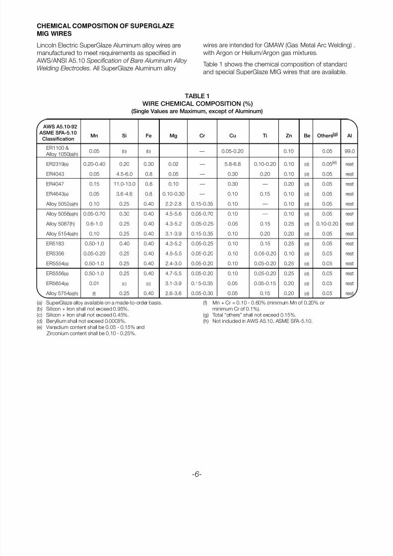
Lincoln Electric SuperGlaze Aluminum alloy wires are
manufactured to meet requirements as specified in
AWS/ANSI A5.10 Specification of Bare Aluminum Alloy
Welding Electrodes. All SuperGlaze Aluminum alloy
wires are intended for GMAW (Gas Metal Arc Welding) .
with Argon or Helium/Argon gas mixtures.
Table 1 shows the chemical composition of standard
and special SuperGlaze MIG wires that are available.
AWS A5.10-92
ASME SFA-5.10
ClassificationMn Si Fe Mg Cr Cu Ti Zn Be Others(g) Al
ER1100 & 0.05 (b) (b) — — 0.05-0.20 — 0.10 0.05 99.0
Alloy 1050(a)(h)
ER2319(a) 0.20-0.40 0.20 0.30 0.02 — 5.8-6.8 0.10-0.20 0.10 (d) 0.05(e) rest
ER4043 0.05 4.5-6.0 0.8 0.05 — 0.30 0.20 0.10 (d) 0.05 rest
ER4047 0.15 11.0-13.0 0.8 0.10 — 0.30 — 0.20 (d) 0.05 rest
ER4643(a) 0.05 3.6-4.6 0.8 0.10-0.30 — 0.10 0.15 0.10 (d) 0.05 rest
Alloy 5052(a)(h) 0.10 0.25 0.40 2.2-2.8 0.15-0.35 0.10 — 0.10 (d) 0.05 rest
Alloy 5056(a)(h) 0.05-0.20 0.30 0.40 4.5-5.6 0.05-0.20 0.10 — 0.10 (d) 0.05 rest
Alloy 5087(h) 0.6-1.0 0.25 0.40 4.3-5.2 0.05-0.25 0.05 0.15 0.25 (d) 0.10-0.20 rest
Alloy 5154(a)(h) 0.10 0.25 0.40 3.1-3.9 0.15-0.35 0.10 0.20 0.20 (d) 0.05 rest
ER5183 0.50-1.0 0.40 0.40 4.3-5.2 0.05-0.25 0.10 0.15 0.25 (d) 0.05 rest
ER5356 0.05-0.20 0.25 0.40 4.5-5.5 0.05-0.20 0.10 0.06-0.20 0.10 (d) 0.05 rest
ER5554(a) 0.50-1.0 0.25 0.40 2.4-3.0 0.05-0.20 0.10 0.05-0.20 0.25 (d) 0.05 rest
ER5556(a) 0.50-1.0 0.25 0.40 4.7-5.5 0.05-0.20 0.10 0.05-0.20 0.25 (d) 0.05 rest
ER5654(a) 0.01 (c) (c) 3.1-3.9 0.15-0.35 0.05 0.05-0.15 0.20 (d) 0.05 rest
Alloy 5754(a)(h) (f) 0.25 0.40 2.6-3.6 0.05-0.30 0.05 0.15 0.20 (d) 0.05 rest
TABLE 1WIRE CHEMICAL COMPOSITION (%)
(Single Values are Maximum, except of Aluminum)
(a) SuperGlaze alloy available on a made-to-order basis.
(b) Silicon + Iron shall not exceed 0.95%.
(c) Silicon + Iron shall not exceed 0.45%.
(d) Beryllium shall not exceed 0.0008%.
(e) Vanadium content shall be 0.05 - 0.15% and
Zirconium content shall be 0.10 - 0.25%.
-6-
(f) Mn + Cr = 0.10 - 0.60% (minimum Mn of 0.20% or
minimum Cr of 0.1%).
(g) Total “others” shall not exceed 0.15%.
(h) Not included in AWS A5.10, ASME SFA-5.10.
CHEMICAL COMPOSITION OF SUPERGLAZE
MIG WIRES
8/10/2019 Aluminium Mig Welding Guide.pdf
http://slidepdf.com/reader/full/aluminium-mig-welding-guidepdf 7/28
ELECTRODE DESCRIPTION AND SELECTION
ER1100 The 1XXX series of filler alloys make the soft-
est electrode wire and require extra care to ensure good
feeding. Electrical and chemical applications for aluminum
often use base metal with little or no alloying elements
and filler alloys for these are often required to have simi-
lar compositions. ER1100 is suitable in most cases
although it contains a small amount of Cu.
ER2319 This alloy is designed to weld the 2XXX alloys2219 and 2519. While these alloys can also be welded
with ER4043, ER2319 gives significantly higher welded
properties.
ER4043, ER4047 ER4043 was developed for the
welding of heat-treatable base alloys and more specifi-
cally the 6XXX series alloys. It has a lower melting point
and more fluidity than the 5XXX series filler alloys, and is
preferred by most welders because of its operating
characteristics and is less sensitive to weld cracking
with the 6XXX series base alloys. These alloys are not
suitable for welding Al-Mg alloys (specifically alloys
5083, 5086, 5456) because excessive magnesium-sili-
cide (Mg2Si) may develop in the weld structure to
decrease ductility and increase crack sensitivity.
ER4047 was developed as a brazing filler metal to take
advantage of its much lower melting point and higher
fluidity, but it is used as a welding filler alloy also.
ER4047 can be used as a substitute for ER4043 to pro-
vide increased Si in the weld metal to minimize hot
cracking and to produce higher fillet weld shear
strengths. All 4XXX series filler alloys are suitable for
sustained elevated temperature service, i.e. above
150°F (65°C).
ER4643 This alloy is designed for one purpose only.
There is enough magnesium added to this alloy so that itwill respond to heat treatment. It is designed for use on
weldments which will be completely re-heat treated (ie,
solution heat treated, quenched and aged) after welding
and will provide the highest joint strength of any of the
filler metals under these circumstances.
ER5356, ER5183, ER5554, ER5556, ER5087 These
alloys are designed for the welding of 5XXX series base
alloys to themselves and other alloys. Because of their
higher hardness and strength, the feedability of the
5XXX filler alloys in GMAW is significantly better than
that of ER4043 or ER4047.
ER5356 is the most commonly used 5XXX filler alloy. Itis suitable for welding any of the 5XXX base materials.
However, when welding some of the stronger 5XXX
alloys, such as 5083 or 5654 where welded tensile
strengths of 40ksi (276 MPa) or greater are required,
ER5356 may not be quite strong enough.
In cases where 5356 doesn’t meet the minimum
required tensile stress, filler alloys ER5556, or ER5183
can be used. These alloys, which contain increased
amounts of magnesium, manganese, and/or zirconium,
are capable of meeting minimum required welded ten-
sile stresses for the higher strength 5XXX alloys.
ER5356, ER5556 and ER5183 and are also suitable for
welding the 5XXX aloys to 6XXX and weldable 7XXX
alloys. However, since these alloys contain magnesium
levels above 3%, they are not suitable for use in appli-
cations where the service temperature exceeds 150°F
(65°C). Prolonged exposure above 150°F (65°C) will
sensitize these alloys to stress corrosion cracking andresult in premature failure. For the same reason, post
weld stress relieving or post weld aging operations
should not be performed when these filler alloys are used.
ER5554 is intended as a matching filler alloy when
welding 5454 base materials. This alloy is a lower
magnesium content alloy and is often used for auto-
motive wheels, over the road trailers, and rail tank cars
where the weld filler metal chemistry must closely match
the base material chemistry to maximize corrosion
performance.
FILLER ALLOY SELECTION
Selection of the most suitable filler alloy for each weld-
ing application could be simple when structures are to
be built of the common alloys using common fabrication
practices and when they are to be exposed to common
service conditions. However, special service conditions
and/or special base alloys may require special filler
alloys. The following metal selection methodology
should be followed:
1. Determine base metals and thicknesses.
2. Determine process and joint geometry.
3. Determine requirements:
Cracking resistance,
Weld metal strength and ductility.
Corrosion resistance,
Weld performance at elevated temperatures,
Weld metal fluidity.
Weld metal color match.
4. For “nonheat-treatable alloys”: use filler selection
charts with attention to requirements. Note that
Medium Mg 5XXX materials such as 5052 can be
sensitive to hot cracking. Dilution may need to be
considered where strength is important.
For “heat-treatable alloys”: Dilution, hot cracking,
HAZ cracking, ductility and heat treatment after
welding needs to be considered in addition torequirements.
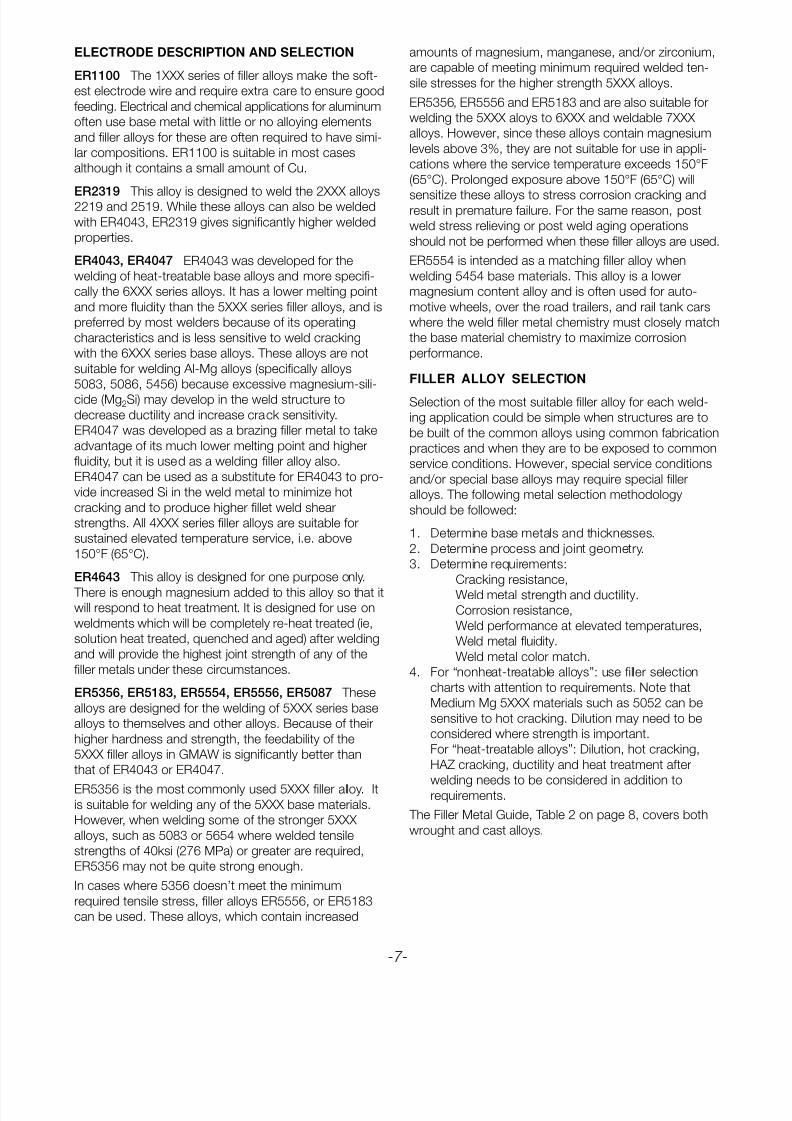
The Filler Metal Guide, Table 2 on page 8, covers both
wrought and cast alloys.
-7-
8/10/2019 Aluminium Mig Welding Guide.pdf
http://slidepdf.com/reader/full/aluminium-mig-welding-guidepdf 8/28
6061
356.0 6063
319.0 357.0 7005 k 6101
333.0 359.0 511.0 7039 6201 1060
354.0 413.0 512.0 710.0 6151 1070
Base 355.0 444.0 513.0 711.0 6351 5154 5052 5005 2219 2014 1100 1080
Metal 380.0 443.0 514.0 712.0 6070 6951 5456 5454 5254 a 5086 5083 5652 a 5050 3004 2519 2036 3003 1350
10601070 4145 4043 5356 5356 4043 4043 5356 4043 5356 5356 5356 4043 1100 4043 4145 4145 1100 1188
1080 c, i i, f c,e,i c,e,i i i c i c,e,i c c i c c j1350
1100 4145 4043 5356 5356 4043 4043 5356 4043 5356 5356 5356 4043 4043 4043 4145 4145 1100
3003 c,i i,f c,e,i c,e,i i i c e,i c,e,i c c e,i e e c
2014 4145 4145 4145 4145 4145 4145
2036 g g g
2219 4145 4145 4043 4043 4043 4043 4043 4043 4043 4043 4043 4043 4043 4043 2319
2519 g,c,i c,i i i f,i f,i i i i c,f,i
3004 4043 4043 5654 5356 4043 4043 5356 5654 5654 5356 5356 4043 4043 4043
i i b e e b e b b e e e,i e e
5005 4043 4043 5654 5356 4043 4043 5356 5654 5654 5356 5356 4043 4043
5050 i i b e e b e b b e e e,i d,e
5052 4043 4043 5654 5356 5356 5356 5356 5654 5654 5356 5356 5654
5652 i b,i b e b,c b,c b b b e e a,b,c
5083 5356 5356 5183 5356 5356 5183 5356 5356 5356 5183c,e,i e e e e b e e e e
5086 5356 5356 5356 5356 5356 5356 5356 5356 5356
c,e,i e e e e e b b e
5154 4043 5654 5356 5356 5356 5356 5654 5654
5254 a b,i b b b,c b,c b a a,b
5454 4043 4043 5654 5356 5356 5356 5356 5554
i b,i b b b,c b,c b c,e
5456 5356 5356 5556 5356 5356 5556
c,e,i e e e e e
6061
6063
6101 4145 4043 5356 5356 4043 40436201 c,i f,i b,c b,c,i b,i b,i
6151
63516951
6070 4145 4043 5356 5356 4043
c,i f,i c,e c,e,i e,i
7005 k
7039
710.0 4043 4043 5356 5356
711.0 i b,i b e
712.0
511.0
512.0 4043 5654
513.0 b,i b,d
514.0
356.0
357.0
359.0 4145 4043
413.0 c,i d,i
444.0443.0
319.0
333.0
354.0 4145
355.0 d,c,i
380.0
TABLE 2 - FILLER METAL GUIDE
ADDITIONAL GUIDELINES
1. Service conditions such as immersion in fresh or salt water,
exposure to specific chemicals, or exposure sustained hightemperature (over 150°F) may limit the choice of filler metals.
Filler alloys 5356, 5183, 5556 and 5654 are not recommended
for sustained elevated temperature service.
2. Guide lines in this table apply to gas shielded arc welding
processes.
3. Where no filler metal is listed, the base metal combination is
not recommended for welding.
The serviceability of a product or structure utilizing this type of information is and must be the sole responsi-bility of the builder/user. Many variables beyond the control of The Lincoln Electric Company affect theresults obtained in applying this type of information. These variables include, but are not limited to, weldingprocedure, plate chemistry and temperature, weldment design, fabrication methods and service requirements.
-8-
Notes: All filler materials are listed in AWS specification A5.10.
a. Base metal alloys 5652 and 5254 are used for hydrogen
peroxide service, 5654 filler metal is used for welding both
alloys for low temperature [150°F (65°C)] service.
b. 5183, 5356, 5454, 5556 and 5654 may be used. In some
cases they provide improved color match after anodizing,
highest weld ductility and higher weld strength. 5554 is
suitable for elevated temperature service.
c. 4043 may be used for some applications.
d. Filler metal with the same analysis as the base metal is
sometimes used.
e. 5183, 5356 or 5556 may be used.
f. 4145 may be used for some applications.
g. 2319 may be used for some applications.
i. 4047 may be used for some applications.
j. 1100 may be used for some applications.
k. This refers to 7005 extrusions only.
8/10/2019 Aluminium Mig Welding Guide.pdf
http://slidepdf.com/reader/full/aluminium-mig-welding-guidepdf 9/28
HOW ALLOYS EFFECT MECHANICAL PROPERTIES
The weld deposit is a mixture of the filler metal and base
metal. Strength, ductility, resistance to weld cracking,
corrosion resistance, heat-treatability and other proper-
ties may be influenced by the amount of dilution of the
weld metal by the base metal. Dilution is a function of
joint design, welding process and welding procedure.
Weld cracking tendencies are generally reduced by
keeping base alloy dilution of the weld metal to a
minimum. Edge prepared joints reduce dilution of theweld by base metal and thus reduce the possibility of
hot cracking. In general, preheating should be avoided,
multiple passes are preferred over fewer passes, and
welding speeds should be as high as practical.
Typical mechanical properties of gas shielded arc
welded butt joints in nonheat-treatable and heat-treatable
alloys are listed in Table 3 on page 10.
In examining Table 3, it is clear that the welded
strengths of most aluminum alloys are lower than the
tensile strength of the starting material. In general, it is
not possible when welding aluminum alloys, to produce
welds as strong as the parent material. In order to
understand why this is so, some of the metallurgy of
heat-treatable and nonheat-treatable aluminum alloys
must be discussed.
The nonheat-treatable alloys, (1XXX, 3XXX, 4XXX and
5XXX), are not hardenable by heat treatment. They
come off the hot mill, are annealed in a large furnace to
obtain the “O” temper condition, and then are cold
rolled (or otherwise cold worked) to strengthen them. If
they are welded, the heat of welding acts as a local
annealing treatment for the heat affected zone (HAZ).
The mechanical properties in the HAZ are those of the
annealed (ie “O” temper) material. It makes no difference
what temper the material is in before welding. After
welding, the properties are those of the “O” temper.
Therefore, although welds in “O” temper materials will
be as strong as the starting material, welds in materials
in other tempers will be weaker, sometimes significantly,
than the starting material. There is no practical wayto
restore the strength lost during welding. There is no
heat treatment which will help.
The situation when using heat-treatable alloys, (2XXX,
6XXX and 7XXX), is somewhat more complex. These
alloys are heat treated at the mill by holding at approxi-
mately 1000°F (538°C) for a short time. This is called asolution heat treatment. The alloy is then quenched,
usually in water. If the process is stopped at this point,
the material is said to be in the T4 (naturally aged)
temper. However, the material can be further increased
in strength by performing an aging heat treatment at
approximately 400°F (204°C) for one hour. At this point,
the material is said to be in the T6 temper. Most heat-
treatable alloys are sold in this temper.
When T4 or T6 materials are welded, the heat of weld-
ing affects the properties in the HAZ, reducing them.
Properties are usually not reduced all the way down to
the “O” temper. It is difficult to give a general rule
regarding the reduction in properties. The specific value
depends on the alloy and temper under consideration.
However, as an example, 6061-T6 is required to have a
minimum utlimate tensile strength of 40 ksi (276 MPa)
before welding. In the welded condition, most codes
require a minimum tensile stress of 24 ksi (165 MPa), sothat the reduction can be significant.
However, it is possible to restore the mechanical prop-
erties, at least in part, by heat treating after welding.
Alloys welded in the T6 temper will show a slight
improvement in strength if they are aged after welding at
approximately 400°F (204°C) for one hour. A much
larger improvement will be observed if the material is
welded in the T4 temper and aged at 400°F (204°C) for
one hour after welding. Finally, with the proper choice of
weld filler alloy, the welded assembly can be re-solution
aged, quenched, and aged to obtain the full T6 proper-
ties. This last course of action is clearly not always prac-
tical, especially for large structures, but may be practical
for smaller ones.
Almost all alloys, except 7XXX, of the common aluminum
alloys can be welded without impairing their corrosion
resistance. Also, in general the choice of welding
process does not influence corrosion resistance.
The excellent corrosion resistance of the 1XXX, 3XXX,
4XXX and 5XXX series nonheat-treatable alloys is generally
not affected by welding. Joints involving combinations
of these alloys also have good corrosion resistance. In
prolonged service at elevated temperatures [above
150°F (65°C)] of 5XXX series alloys containing morethan 3% magnesium however, these alloys eventually
become sensitive to stress corrosion. In this type of ser-
vice lower magnesium content alloys like 5454 should
be used.
The aluminum-magnesium-silicon heat-treatable alloys
such as 6061 and 6063 have generally good corrosion
resistance, unwelded or welded. However, immersed in
an electrolyte such as sea water, the HAZ may corrode
preferentially.
The 2XXX and 7XXX series heat-treatable alloys,
containing substantial amounts of copper and zinc and
some magnesium, may have corrosion resistancelowered by the heat of welding. Grain boundary
precipitation in the HAZ creates a difference in electrical
potential from the remainder of the weld metal and, if
there is an electrolyte present, selective corrosive attack
on the grain boundaries is likely to occur. Postweld
heat-treatment provides a more homogeneous structure
and improves the corrosion resistance of these alloys.
However, these are not the alloys of choice where
corrosion resistance is of primary importance.
-9-

8/10/2019 Aluminium Mig Welding Guide.pdf
http://slidepdf.com/reader/full/aluminium-mig-welding-guidepdf 10/28
-10-
Elongation
Base Filler Tensile Strength Yield Strength Tensile Free Bend
Alloy Alloy (ksi) (MPa) (ksi) (MPa) (%) (%)
Nonheat-Treatable Alloys
1100 1100 13 90 4.5 31 29 54
3003 1100 16 110 7 48 24 585005 5356 16 110 7 48 15 32
5050 5356 23 158 8 55 18 36
5052 5356 28 193 13 90 19 39
5083 5183 43 296 24 165 16 34
5086 5356 39 269 17 117 17 38
Heat-Treatable Alloys
2219-T87 2319 35 241 26 179 3 15
6061-T6 4043 27 186 18 124 8 16
6061-T6 5356 30 207 19 131 11 25
6063-T6 4043 20 138 12 83 8 167005-T53 5556 44 303 25 172 10 33
TABLE 3
TYPICAL AS-WELDED MECHANICAL PROPERTIES OF GMAW WELDED BUTT JOINTS
8/10/2019 Aluminium Mig Welding Guide.pdf
http://slidepdf.com/reader/full/aluminium-mig-welding-guidepdf 11/28
CHART 2
WFS vs. AMPS
550
500
450
400
350
300
250
200
150
150 175 200 225 250
3/64” 5356
3/64” 4043
5356 4043 Amps WFS Amps WFS
150 325 150 270175 385 175 315200 440 200 360225 495 225 410250 545 250 460
-11-
WFS
(in./min)
AMPS
III. HOW PHYSICAL PROPERTIES EFFECT WELDING PROCEDURES
CHART 1
100
80
60
40
20
0
Copper 1100 4043 5356
Electrical Conductivity
(100%)
(59%)
(42%)
(29%)
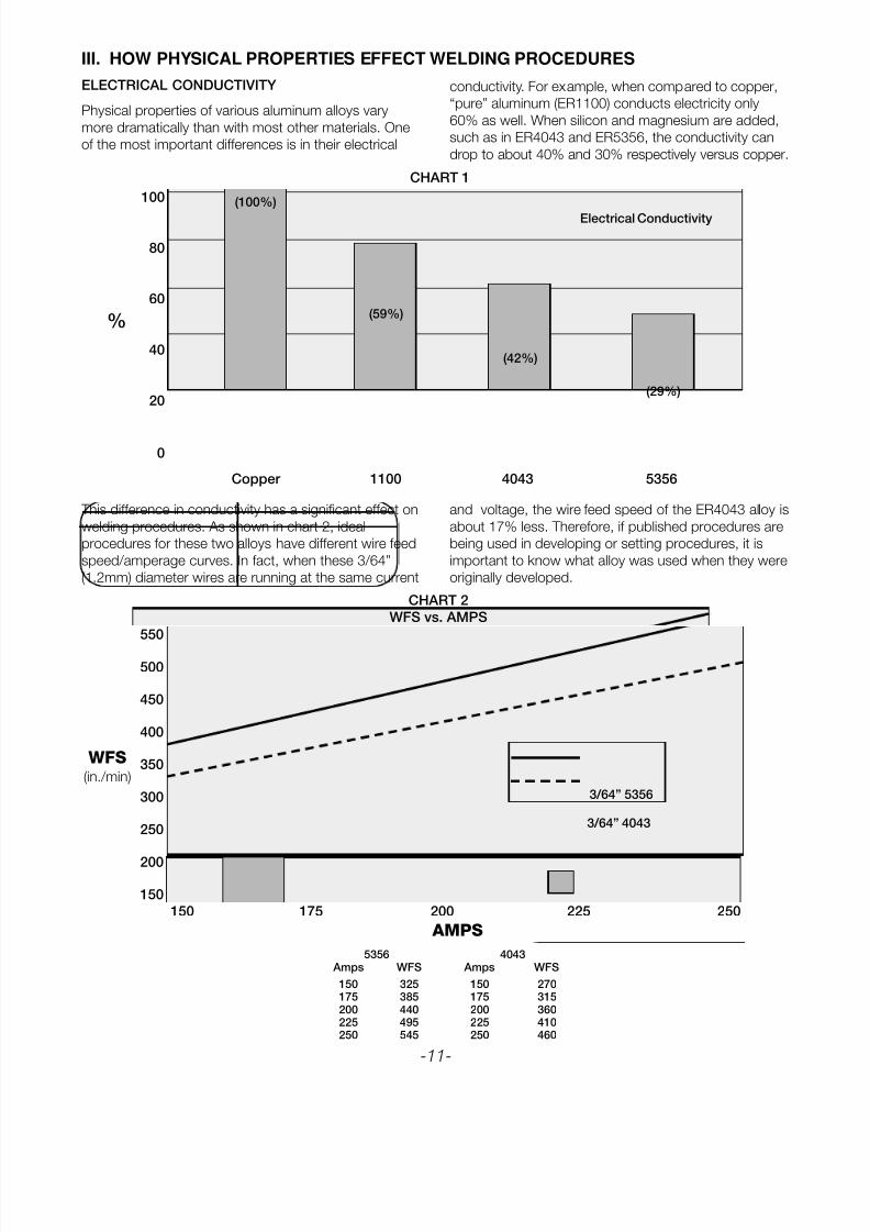
ELECTRICAL CONDUCTIVITY
Physical properties of various aluminum alloys vary
more dramatically than with most other materials. One
of the most important differences is in their electrical
conductivity. For example, when compared to copper,
“pure” aluminum (ER1100) conducts electricity only
60% as well. When silicon and magnesium are added,
such as in ER4043 and ER5356, the conductivity can
drop to about 40% and 30% respectively versus copper.
This difference in conductivity has a significant effect on
welding procedures. As shown in chart 2, ideal
procedures for these two alloys have different wire feed
speed/amperage curves. In fact, when these 3/64”
(1.2mm) diameter wires are running at the same current
and voltage, the wire feed speed of the ER4043 alloy is
about 17% less. Therefore, if published procedures are
being used in developing or setting procedures, it is
important to know what alloy was used when they were
originally developed.
%
8/10/2019 Aluminium Mig Welding Guide.pdf
http://slidepdf.com/reader/full/aluminium-mig-welding-guidepdf 12/28
-12-
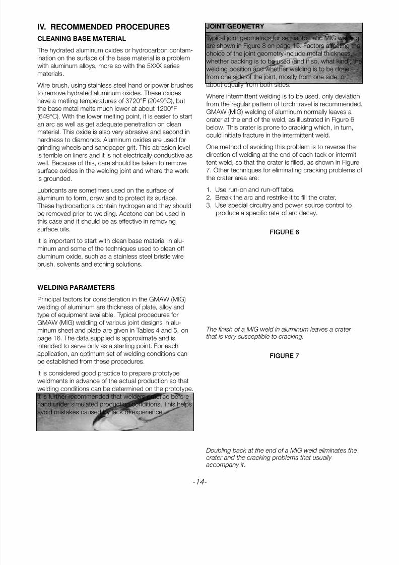
FIGURE 2
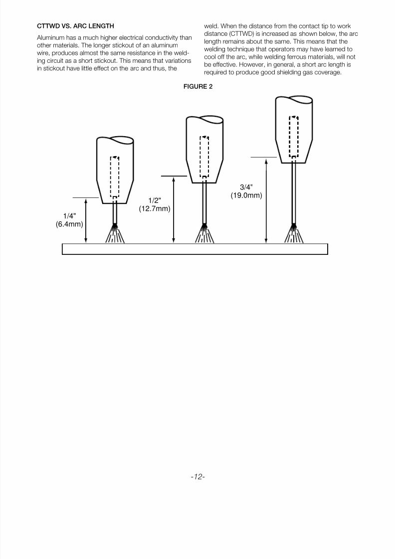
CTTWD VS. ARC LENGTH
Aluminum has a much higher electrical conductivity than
other materials. The longer stickout of an aluminum
wire, produces almost the same resistance in the weld-
ing circuit as a short stickout. This means that variations
in stickout have little effect on the arc and thus, the
weld. When the distance from the contact tip to work
distance (CTTWD) is increased as shown below, the arc
length remains about the same. This means that the
welding technique that operators may have learned to
cool off the arc, while welding ferrous materials, will not
be effective. However, in general, a short arc length is
required to produce good shielding gas coverage.
1/4"(6.4mm)
1/2"(12.7mm)
3/4"
(19.0mm)
8/10/2019 Aluminium Mig Welding Guide.pdf
http://slidepdf.com/reader/full/aluminium-mig-welding-guidepdf 13/28
-13-
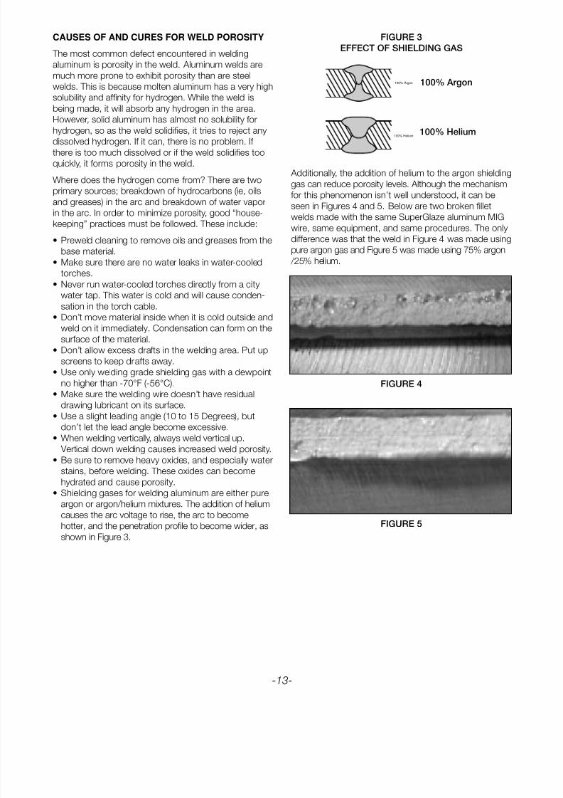
FIGURE 3
EFFECT OF SHIELDING GAS
100% Argon
100% Helium
100% Argon
100% Helium
CAUSES OF AND CURES FOR WELD POROSITY
The most common defect encountered in welding
aluminum is porosity in the weld. Aluminum welds are
much more prone to exhibit porosity than are steel
welds. This is because molten aluminum has a very high
solubility and affinity for hydrogen. While the weld is
being made, it will absorb any hydrogen in the area.
However, solid aluminum has almost no solubility for
hydrogen, so as the weld solidifies, it tries to reject any
dissolved hydrogen. If it can, there is no problem. If there is too much dissolved or if the weld solidifies too
quickly, it forms porosity in the weld.
Where does the hydrogen come from? There are two
primary sources; breakdown of hydrocarbons (ie, oils
and greases) in the arc and breakdown of water vapor
in the arc. In order to minimize porosity, good “house-
keeping” practices must be followed. These include:
• Preweld cleaning to remove oils and greases from the
base material.
• Make sure there are no water leaks in water-cooled
torches.
• Never run water-cooled torches directly from a city
water tap. This water is cold and will cause conden-
sation in the torch cable.
• Don’t move material inside when it is cold outside and
weld on it immediately. Condensation can form on the
surface of the material.
• Don’t allow excess drafts in the welding area. Put up
screens to keep drafts away.
• Use only welding grade shielding gas with a dewpoint
no higher than -70°F (-56°C).
• Make sure the welding wire doesn’t have residual
drawing lubricant on its surface.
• Use a slight leading angle (10 to 15 Degrees), butdon’t let the lead angle become excessive.
• When welding vertically, always weld vertical up.
Vertical down welding causes increased weld porosity.
• Be sure to remove heavy oxides, and especially water
stains, before welding. These oxides can become
hydrated and cause porosity.
• Shielding gases for welding aluminum are either pure
argon or argon/helium mixtures. The addition of helium
causes the arc voltage to rise, the arc to become
hotter, and the penetration profile to become wider, as
shown in Figure 3.
Additionally, the addition of helium to the argon shielding
gas can reduce porosity levels. Although the mechanism
for this phenomenon isn’t well understood, it can be
seen in Figures 4 and 5. Below are two broken fillet
welds made with the same SuperGlaze aluminum MIG
wire, same equipment, and same procedures. The only
difference was that the weld in Figure 4 was made using
pure argon gas and Figure 5 was made using 75% argon
/25% helium.
FIGURE 4
FIGURE 5
8/10/2019 Aluminium Mig Welding Guide.pdf
http://slidepdf.com/reader/full/aluminium-mig-welding-guidepdf 14/28
-14-
FIGURE 6
FIGURE 7
CLEANING BASE MATERIAL
The hydrated aluminum oxides or hydrocarbon contam-
ination on the surface of the base material is a problem
with aluminum alloys, more so with the 5XXX series
materials.
Wire brush, using stainless steel hand or power brushes
to remove hydrated aluminum oxides. These oxides
have a metling temperatures of 3720°F (2049°C), butthe base metal melts much lower at about 1200°F
(649°C). With the lower melting point, it is easier to start
an arc as well as get adequate penetration on clean
material. This oxide is also very abrasive and second in
hardness to diamonds. Aluminum oxides are used for
grinding wheels and sandpaper grit. This abrasion level
is terrible on liners and it is not electrically conductive as
well. Because of this, care should be taken to remove
surface oxides in the welding joint and where the work
is grounded.
Lubricants are sometimes used on the surface of
aluminum to form, draw and to protect its surface. These hydrocarbons contain hydrogen and they should
be removed prior to welding. Acetone can be used in
this case and it should be as effective in removing
surface oils.
It is important to start with clean base material in alu-
minum and some of the techniques used to clean off
aluminum oxide, such as a stainless steel bristle wire
brush, solvents and etching solutions.
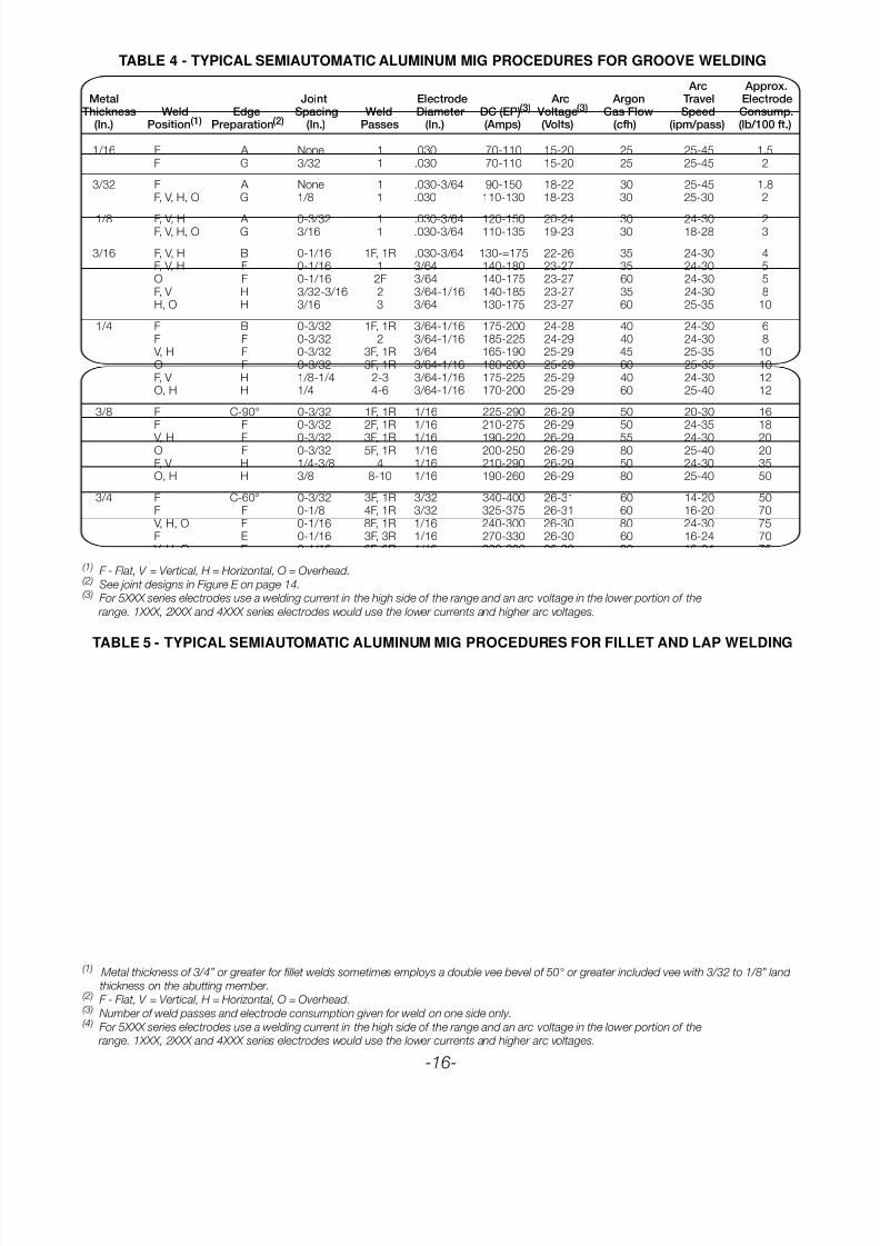
WELDING PARAMETERS
Principal factors for consideration in the GMAW (MIG)welding of aluminum are thickness of plate, alloy and
type of equipment available. Typical procedures for
GMAW (MIG) welding of various joint designs in alu-
minum sheet and plate are given in Tables 4 and 5, on
page 16. The data supplied is approximate and is
intended to serve only as a starting point. For each
application, an optimum set of welding conditions can
be established from these procedures.
It is considered good practice to prepare prototype
weldments in advance of the actual production so that
welding conditions can be determined on the prototype.
It is further recommended that welders practice before-hand under simulated production conditions. This helps
avoid mistakes caused by lack of experience.
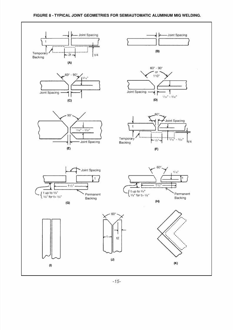
JOINT GEOMETRY
Typical joint geometrics for semiautomatic MIG welding
are shown in Figure 8 on page 15. Factors affecting the
choice of the joint geometry include metal thickness,
whether backing is to be used (and if so, what kind), the
welding position and whether welding is to be done
from one side of the joint, mostly from one side, or
about equally from both sides.
Where intermittent welding is to be used, only deviationfrom the regular pattern of torch travel is recommended.
GMAW (MIG) welding of aluminum normally leaves a
crater at the end of the weld, as illustrated in Figure 6
below. This crater is prone to cracking which, in turn,
could initiate fracture in the intermittent weld.
One method of avoiding this problem is to reverse the
direction of welding at the end of each tack or intermit-
tent weld, so that the crater is filled, as shown in Figure
7. Other techniques for eliminating cracking problems of
the crater area are:
1. Use run-on and run-off tabs.
2. Break the arc and restrike it to fill the crater.3. Use special circuitry and power source control to
produce a specific rate of arc decay.
IV. RECOMMENDED PROCEDURES
The finish of a MIG weld in aluminum leaves a crater that is very susceptible to cracking.
Doubling back at the end of a MIG weld eliminates thecrater and the cracking problems that usually accompany it.
8/10/2019 Aluminium Mig Welding Guide.pdf
http://slidepdf.com/reader/full/aluminium-mig-welding-guidepdf 15/28
FIGURE 8 - TYPICAL JOINT GEOMETRIES FOR SEMIAUTOMATIC ALUMINUM MIG WELDING.
-15-
8/10/2019 Aluminium Mig Welding Guide.pdf
http://slidepdf.com/reader/full/aluminium-mig-welding-guidepdf 16/28
TABLE 4 - TYPICAL SEMIAUTOMATIC ALUMINUM MIG PROCEDURES FOR GROOVE WELDING
TABLE 5 - TYPICAL SEMIAUTOMATIC ALUMINUM MIG PROCEDURES FOR FILLET AND LAP WELDING
Arc Approx.Metal Joint Electrode Arc Argon Travel Electrode
Thickness Weld Edge Spacing Weld Diameter DC (EP)(3) Voltage(3) Gas Flow Speed Consump.(In.) Position(1) Preparation(2) (In.) Passes (In.) (Amps) (Volts) (cfh) (ipm/pass) (lb/100 ft.)
1/16 F A None 1 .030 70-110 15-20 25 25-45 1.5F G 3/32 1 .030 70-110 15-20 25 25-45 2
3/32 F A None 1 .030-3/64 90-150 18-22 30 25-45 1.8F, V, H, O G 1/8 1 .030 110-130 18-23 30 25-30 2
1/8 F, V, H A 0-3/32 1 .030-3/64 120-150 20-24 30 24-30 2F, V, H, O G 3/16 1 .030-3/64 110-135 19-23 30 18-28 3
3/16 F, V, H B 0-1/16 1F, 1R .030-3/64 130-=175 22-26 35 24-30 4F, V, H F 0-1/16 1 3/64 140-180 23-27 35 24-30 5O F 0-1/16 2F 3/64 140-175 23-27 60 24-30 5F, V H 3/32-3/16 2 3/64-1/16 140-185 23-27 35 24-30 8H, O H 3/16 3 3/64 130-175 23-27 60 25-35 10
1/4 F B 0-3/32 1F, 1R 3/64-1/16 175-200 24-28 40 24-30 6F F 0-3/32 2 3/64-1/16 185-225 24-29 40 24-30 8
V, H F 0-3/32 3F, 1R 3/64 165-190 25-29 45 25-35 10O F 0-3/32 3F, 1R 3/64-1/16 180-200 25-29 60 25-35 10F, V H 1/8-1/4 2-3 3/64-1/16 175-225 25-29 40 24-30 12O, H H 1/4 4-6 3/64-1/16 170-200 25-29 60 25-40 12
3/8 F C-90° 0-3/32 1F, 1R 1/16 225-290 26-29 50 20-30 16F F 0-3/32 2F, 1R 1/16 210-275 26-29 50 24-35 18
V, H F 0-3/32 3F, 1R 1/16 190-220 26-29 55 24-30 20O F 0-3/32 5F, 1R 1/16 200-250 26-29 80 25-40 20F, V H 1/4-3/8 4 1/16 210-290 26-29 50 24-30 35O, H H 3/8 8-10 1/16 190-260 26-29 80 25-40 50
3/4 F C-60° 0-3/32 3F, 1R 3/32 340-400 26-31 60 14-20 50F F 0-1/8 4F, 1R 3/32 325-375 26-31 60 16-20 70
V, H, O F 0-1/16 8F, 1R 1/16 240-300 26-30 80 24-30 75F E 0-1/16 3F, 3R 1/16 270-330 26-30 60 16-24 70
V, H, O E 0-1/16 6F, 6R 1/16 230-280 26-30 80 16-24 75
(1) F - Flat, V = Vertical, H = Horizontal, O = Overhead.(2) See joint designs in Figure E on page 14.(3) For 5XXX series electrodes use a welding current in the high side of the range and an arc voltage in the lower portion of the
range. 1XXX, 2XXX and 4XXX series electrodes would use the lower currents and higher arc voltages.
(1) Metal thickness of 3/4” or greater for fillet welds sometimes employs a double vee bevel of 50° or greater included vee with 3/32 to 1/8” land
thickness on the abutting member.(2) F - Flat, V = Vertical, H = Horizontal, O = Overhead.(3) Number of weld passes and electrode consumption given for weld on one side only.(4) For 5XXX series electrodes use a welding current in the high side of the range and an arc voltage in the lower portion of the
range. 1XXX, 2XXX and 4XXX series electrodes would use the lower currents and higher arc voltages.
Arc Approx.Metal Electrode Arc Argon Travel Electrode
Thickness(1) Weld Weld Diameter DC (EP)(4) Voltage(4) Gas Flow Speed Consump.(3)
(In.) Position(2) Passes(3) (In.) (Amps) (Volts) (cfh) (ipm/pass) (lb/100 ft.)
3/32 F, V, H, O 1 .030 100-130 18-22 30 24-30 1.8
1/8 F 1 .030-3/64 125-150 20-24 30 24-30 2 V, H 1 .030 110-130 19-23 30 24-30 2O 1 .030-3/64 115-140 20-24 40 24-30 2
3/16 F 1 3/64 180-210 22-26 30 24-30 4.5 V, H 1 .030-3/64 130-175 21-25 35 24-30 4.5O 1 .030-3/64 130-190 22-26 45 24-30 4.5
1/4 F 1 3/64-1/16 170-240 24-28 40 24-30 7 V, H 1 3/64 170-210 23-27 45 24-30 7O 1 3/64-1/16 190-220 24-28 60 24-30 7
3/8 F 1 1/16 240-300 26-29 50 18-25 17H,V 3 1/16 190-240 24-27 60 24-30 17O 3 1/16 200-240 25-28 85 24-30 17
3/4 F 4 3/32 360-380 26-30 60 18-25 66H, V 4-6 1/16 260-310 25-20 70 24-30 66O 10 1/16 275-310 25-29 85 24-30 66
-16-
8/10/2019 Aluminium Mig Welding Guide.pdf
http://slidepdf.com/reader/full/aluminium-mig-welding-guidepdf 17/28
V. PULSING AND WAVEFORM MANIPULATION
-17-
EVOLUTION OF POWER SUPPLIES FOR GASMETAL ARC WELDING OF ALUMNINUM
Early power supplies for GMAW were designed to hold
a steady arc length as wire was fed through the torch
and into the weld pool. It was found that the best way
to do this was to set the internal volt/ampere curve of
the power supply so that, once the arc voltage was
selected, the power supply would hold it steady. If thewelder inadvertently pulled away from the weld, which
would increase the arc voltage, the power supply would
allow the current to fall rapidly so that less wire was
burned off and the arc voltage remained the same. If the
welder inadvertently tried to shorten the arc length, the
power suppply increased the current to keep the arc
length constant. In this way, wire burnbacks and/or
birdnests were minimized. This type of power supply
was called a constant voltage (CV) or constant potential
(CP) power supply.
This type of power supply was and is still widely used.
However, when people started to fabricate aluminum inheavy sections, a number of disadvantages were found
using CV power supplies for GMAW. These power
supplies permitted very large fluctuations in current.
Because of its high thermal conductivity, these fluctua-
tions can result in cold lap weld defects in aluminum.
Because of this, for many years it was strongly recom-
mended that all aluminum GMAW be performed with
constant current (CC) or “drooping” power supplies
such as those normally used for SMAW and GTAW.
When this type of power suuply was used, current
fluctuations were minimized. The action of the power
supply still tended to let the arc voltage self-adjust,although not as quickly as if CV power supplies were
used.
However, the situation changed somewhat with the
introduction of inverter, and especially, software controlled
inverter, power supplies. Wide current fluctuations were
no longer encountered and the arc of CV inverter power
supplies was more stable. Because of this, CV inverter
type power supplies are generally acceptable for
GMAW of aluminum alloys and have come into more
general use for welding aluminum. Drooper power sup-
plies still appear to have advantages when welding with
larger diameter wires [3/32” (2.4mm) or greater] on
heavy sections, 1/2” (12.7mm) thickness or greater.
GMAW for aluminum still suffered from one big
disadvantage even with the advent of inverter power
supplies. Unlike steel, short circuiting arc transfer is not
recommended for welding aluminum because short arc
welds in aluminum are prone to fine line lack of fusion
defects. Therefore, GMAW of aluminum alloys was
always recommended to be performed in spray transfer
mode. In order to get spray transfer, we needed a
certain minimum, but relatively high, transition current,
depending on the wire diameter. This restricted aluminum
GMAW to relatively high heat input and, therefore, to
relatively thick material [approximately 1/8” (3.2mm)
minimum thickness].
This barrier was overcome with the advent of pulsed
GMAW. In this process, the current is rapidly pulsed
between a relatively low background current and a high
peak current at severl hundred Hertz. The premise isthat the peak current is high enough to get spray trans-
fer and we transfer metal across the arc in spray trans-
fer while the arc is at this current level. No metal is
transferred across the arc during the periods of back-
ground current. However, the average current, and
average heat input can now be significantly lower than if
we don’t pulse the current. This has made it possible to
routinely GMAW aluminum of thicknesses as low as
0.030” (0.7mm).
Now that pulsed GMAW has become widespread,
Lincoln has taken the next step: the ability to tailor the
details of the weld pulse to optimize the weldingprocess for certain specific characteristics.
Today, Lincoln’s software controlled power sources like
the PowerWave™ 455 have become more sophisticated
and enable the user to manipulate the output
Waveform. Application specific software, like the
WaveDesigner Pro™, has been developed to optimize
the arc characteristics. A modified constant current
output is normally employed as a high frequency pulse
that is one of the main benefits of constant current. This
major benefit is the high-energy heat input during the
peak, which produces the required penetration.
Advantages obtained by pulsing include reduced spat-ter levels, improved puddle fluidity with an increase in
effective travel speeds, and reduced heat input with
lower distortion levels. It may seem like a contradiction
in terms to say that high-energy heat input is obtained
yet heat input and distortion is less. The reason this is
possible is a more effective use of the total heat gener-
ated by the arc. The general term heat input does not
consider the efficiency of the heat transferred to the
base material and weld.
8/10/2019 Aluminium Mig Welding Guide.pdf
http://slidepdf.com/reader/full/aluminium-mig-welding-guidepdf 18/28
-18-
ANATOMY 0F A WAVEFORM
What exactly is the waveform control technology provid-
ed by Wave Designer Pro? With this technology, the
power source responds to changes demanded by the
software instantaneously. Current is raised to a level
higher than the transition current for spray transfer for a
few milliseconds. During this time, the molten droplet is
formed, detached, and it begins its excursion across
the arc. Additional energy can now be applied to the
molten droplet during its descent that allows it to main-tain its fluidity or increase its fluidity. The pulse is now
moving to a low background current that sustains the
arc to cool the cycle, but it prepares for the advance-
ment to the next pulse peak. Keep in mind that the
“waveform” is the means for determing the performance
characteristics of a single molten droplet of electrode.
The area under the waveform determines the amount of
energy applied to that single droplet.
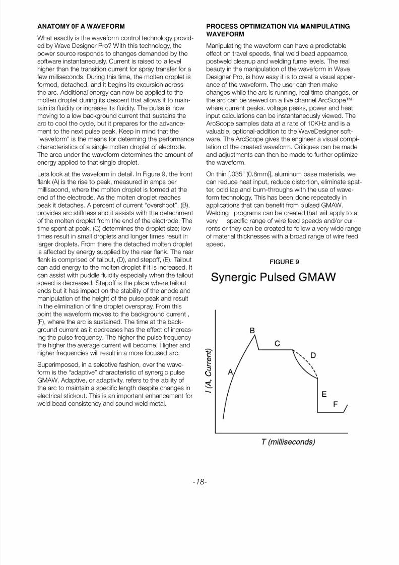
Lets look at the waveform in detail. In Figure 9, the front
flank (A) is the rise to peak, measured in amps per
millisecond, where the molten droplet is formed at the
end of the electrode. As the molten droplet reachespeak it detaches. A percent of current “overshoot”, (B),
provides arc stiffness and it assists with the detachment
of the molten droplet from the end of the electrode. The
time spent at peak, (C) determines the droplet size; low
times result in small droplets and longer times result in
larger droplets. From there the detached molten droplet
is affected by energy supplied by the rear flank. The rear
flank is comprised of tailout, (D), and stepoff, (E). Tailout
can add energy to the molten droplet if it is increased. It
can assist with puddle fluidity especially when the tailout
speed is decreased. Stepoff is the place where tailout
ends but it has impact on the stability of the anode and
manipulation of the height of the pulse peak and resultin the elimination of fine droplet overspray. From this
point the waveform moves to the background current ,
(F), where the arc is sustained. The time at the back-
ground current as it decreases has the effect of increas-
ing the pulse frequency. The higher the pulse frequency
the higher the average current will become. Higher and
higher frequencies will result in a more focused arc.
Superimposed, in a selective fashion, over the wave-
form is the “adaptive” characteristic of synergic pulse
GMAW. Adaptive, or adaptivity, refers to the ability of
the arc to maintain a specific length despite changes in
electrical stickout. This is an important enhancement forweld bead consistency and sound weld metal.
PROCESS OPTIMIZATION VIA MANIPULATING
WAVEFORM
Manipulating the waveform can have a predictable
effect on travel speeds, final weld bead appearnce,
postweld cleanup and welding fume levels. The real
beauty in the manipulation of the waveform in Wave
Designer Pro, is how easy it is to creat a visual apper-
ance of the waveform. The user can then make
changes while the arc is running, real time changes, or
the arc can be viewed on a five channel ArcScope™where current peaks. voltage peaks, power and heat
input calculations can be instantaneously viewed. The
ArcScope samples data at a rate of 10KHz and is a
valuable, optional-addition to the WaveDesigner soft-
ware. The ArcScope gives the engineer a visual compi-
lation of the created waveform. Critiques can be made
and adjustments can then be made to further optimize
the waveform.
On thin [.035” (0.8mm)], aluminum base materials, we
can reduce heat input, reduce distortion, eliminate spat-
ter, cold lap and burn-throughs with the use of wave-
form technology. This has been done repeatedly inapplications that can benefit from pulsed GMAW.
Welding programs can be created that will apply to a
very specific range of wire feed speeds and/or cur-
rents or they can be created to follow a very wide range
of material thicknesses with a broad range of wire feed
speed.
FIGURE 9

8/10/2019 Aluminium Mig Welding Guide.pdf
http://slidepdf.com/reader/full/aluminium-mig-welding-guidepdf 19/28
8/10/2019 Aluminium Mig Welding Guide.pdf
http://slidepdf.com/reader/full/aluminium-mig-welding-guidepdf 20/28
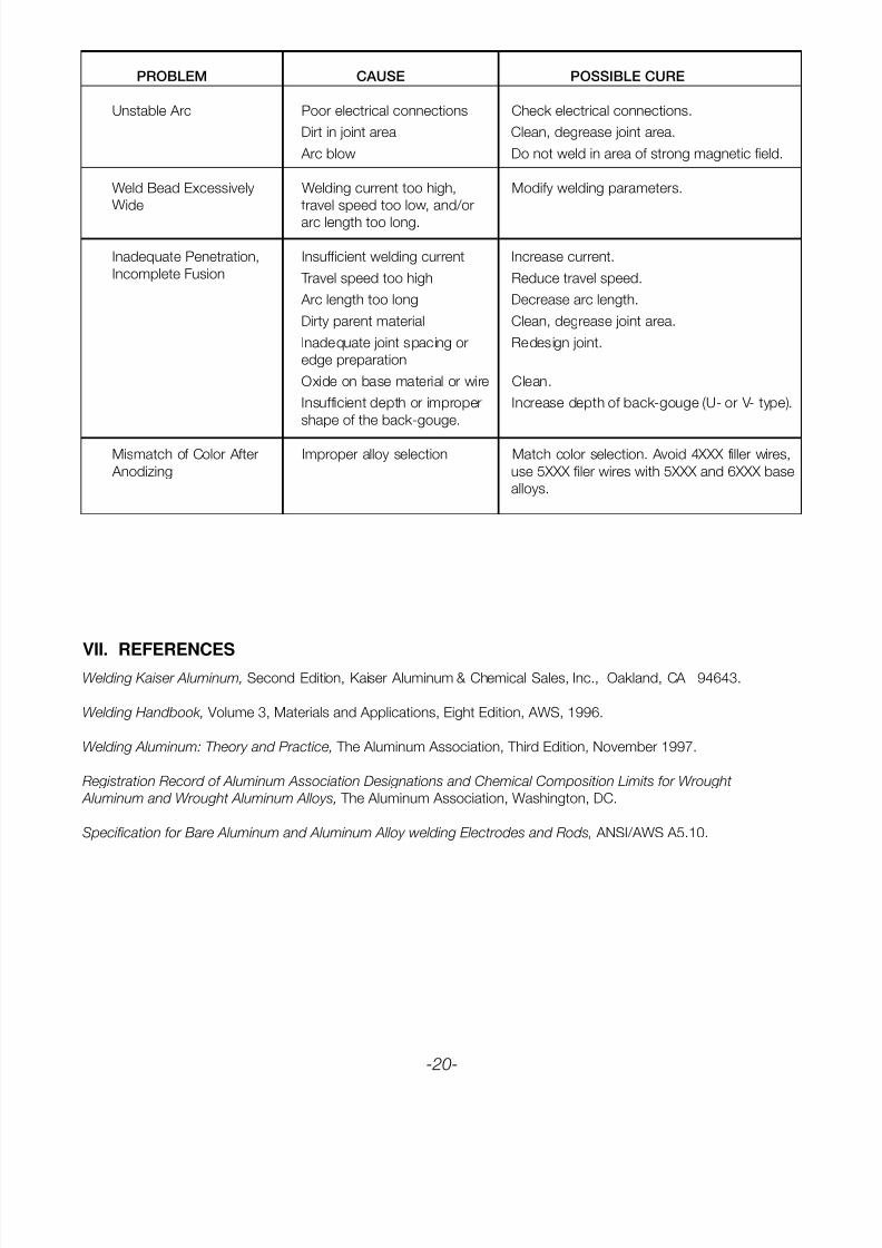
VII. REFERENCESWelding Kaiser Aluminum, Second Edition, Kaiser Aluminum & Chemical Sales, Inc., Oakland, CA 94643.
Welding Handbook, Volume 3, Materials and Applications, Eight Edition, AWS, 1996.
Welding Aluminum: Theory and Practice, The Aluminum Association, Third Edition, November 1997.
Registration Record of Aluminum Association Designations and Chemical Composition Limits for Wrought
Aluminum and Wrought Aluminum Alloys, The Aluminum Association, Washington, DC.
Specification for Bare Aluminum and Aluminum Alloy welding Electrodes and Rods, ANSI/AWS A5.10.
PROBLEM CAUSE POSSIBLE CURE
Unstable Arc Poor electrical connections Check electrical connections.
Dirt in joint area Clean, degrease joint area.
Arc blow Do not weld in area of strong magnetic field.
Weld Bead Excessively Welding current too high, Modify welding parameters.
Wide travel speed too low, and/or
arc length too long.
Inadequate Penetration, Insufficient welding current Increase current.
Incomplete Fusion Travel speed too high Reduce travel speed.
Arc length too long Decrease arc length.
Dirty parent material Clean, degrease joint area.
Inadequate joint spacing or Redesign joint.
edge preparation
Oxide on base material or wire Clean.
Insufficient depth or improper Increase depth of back-gouge (U- or V- type).
shape of the back-gouge.
Mismatch of Color After Improper alloy selection Match color selection. Avoid 4XXX filler wires,
Anodizing use 5XXX filer wires with 5XXX and 6XXX base
alloys.
-20-
8/10/2019 Aluminium Mig Welding Guide.pdf
http://slidepdf.com/reader/full/aluminium-mig-welding-guidepdf 21/28
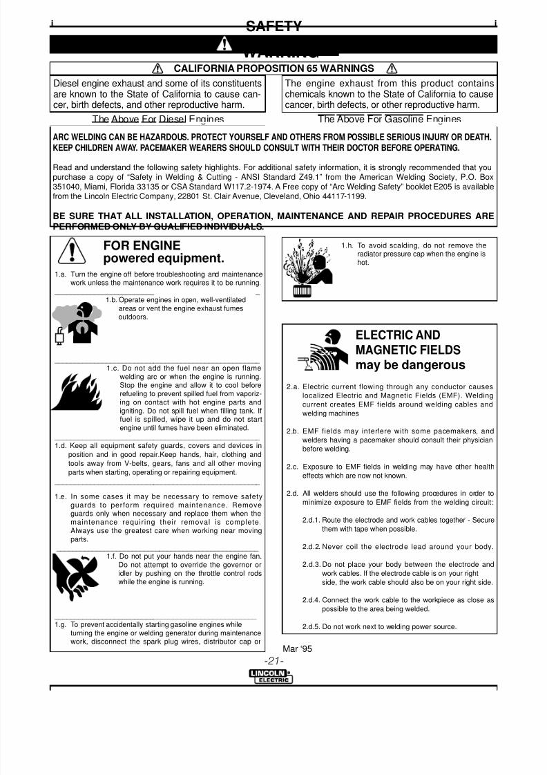
FOR ENGINEpowered equipment.
1.a. Turn the engine off before troubleshooting and maintenancework unless the maintenance work requires it to be running.
____________________________________________________ 1.b. Operate engines in open, well-ventilated
areas or vent the engine exhaust fumesoutdoors.
____________________________________________________ 1.c. Do not add the fuel near an open flame
welding arc or when the engine is running.Stop the engine and allow it to cool beforerefueling to prevent spilled fuel from vaporiz-ing on contact with hot engine parts andigniting. Do not spill fuel when filling tank. Iffuel is spilled, wipe it up and do not startengine until fumes have been eliminated.
____________________________________________________
1.d. Keep all equipment safety guards, covers and devices in
position and in good repair.Keep hands, hair, clothing and
tools away from V-belts, gears, fans and all other moving
parts when starting, operating or repairing equipment.
____________________________________________________
1.e. In some cases it may be necessary to remove safetyguards to perform required maintenance. Removeguards only when necessary and replace them when themaintenance requir ing their removal is complete.Always use the greatest care when working near movingparts.
___________________________________________________ 1.f. Do not put your hands near the engine fan.
Do not attempt to override the governor oridler by pushing on the throttle control rodswhile the engine is running.
___________________________________________________ 1.g. To prevent accidentally starting gasoline engines while
turning the engine or welding generator during maintenancework, disconnect the spark plug wires, distributor cap or
iSAFETYi
ARC WELDING CAN BE HAZARDOUS. PROTECT YOURSELF AND OTHERS FROM POSSIBLE SERIOUS INJURY OR DEATH.KEEP CHILDREN AWAY. PACEMAKER WEARERS SHOULD CONSULT WITH THEIR DOCTOR BEFORE OPERATING.
Read and understand the following safety highlights. For additional safety information, it is strongly recommended that you
purchase a copy of “Safety in Welding & Cutting - ANSI Standard Z49.1” from the American Welding Society, P.O. Box
351040, Miami, Florida 33135 or CSA Standard W117.2-1974. A Free copy of “Arc Welding Safety” booklet E205 is availablefrom the Lincoln Electric Company, 22801 St. Clair Avenue, Cleveland, Ohio 44117-1199.
BE SURE THAT ALL INSTALLATION, OPERATION, MAINTENANCE AND REPAIR PROCEDURES ARE
PERFORMED ONLY BY QUALIFIED INDIVIDUALS.
WARNING
Mar ‘95
ELECTRIC ANDMAGNETIC FIELDSmay be dangerous
2.a. Electric current flowing through any conductor causes
localized Electric and Magnetic Fields (EMF). Welding
current creates EMF fields around welding cables andwelding machines
2.b. EMF fields may interfere with some pacemakers, and
welders having a pacemaker should consult their physician
before welding.
2.c. Exposure to EMF fields in welding may have other health
effects which are now not known.
2.d. All welders should use the following procedures in order to
minimize exposure to EMF fields from the welding circuit:
2.d.1. Route the electrode and work cables together - Secure
them with tape when possible.
2.d.2. Never coil the electrod e lead around your body.
2.d.3. Do not place your body between the electrode and
work cables. If the electrode cable is on your right
side, the work cable should also be on your right side.
2.d.4. Connect the work cable to the workpiece as close as
possible to the area being welded.
2.d.5. Do not work next to welding power source.
1.h. To avoid scalding, do not remove theradiator pressure cap when the engine ishot.
CALIFORNIA PROPOSITION 65 WARNINGS
Diesel engine exhaust and some of its constituentsare known to the State of California to cause can-cer, birth defects, and other reproductive harm.
The engine exhaust from this product containschemicals known to the State of California to causecancer, birth defects, or other reproductive harm.
The Above For Diesel Engines The Above For Gasoline Engines
-21-
8/10/2019 Aluminium Mig Welding Guide.pdf
http://slidepdf.com/reader/full/aluminium-mig-welding-guidepdf 22/28
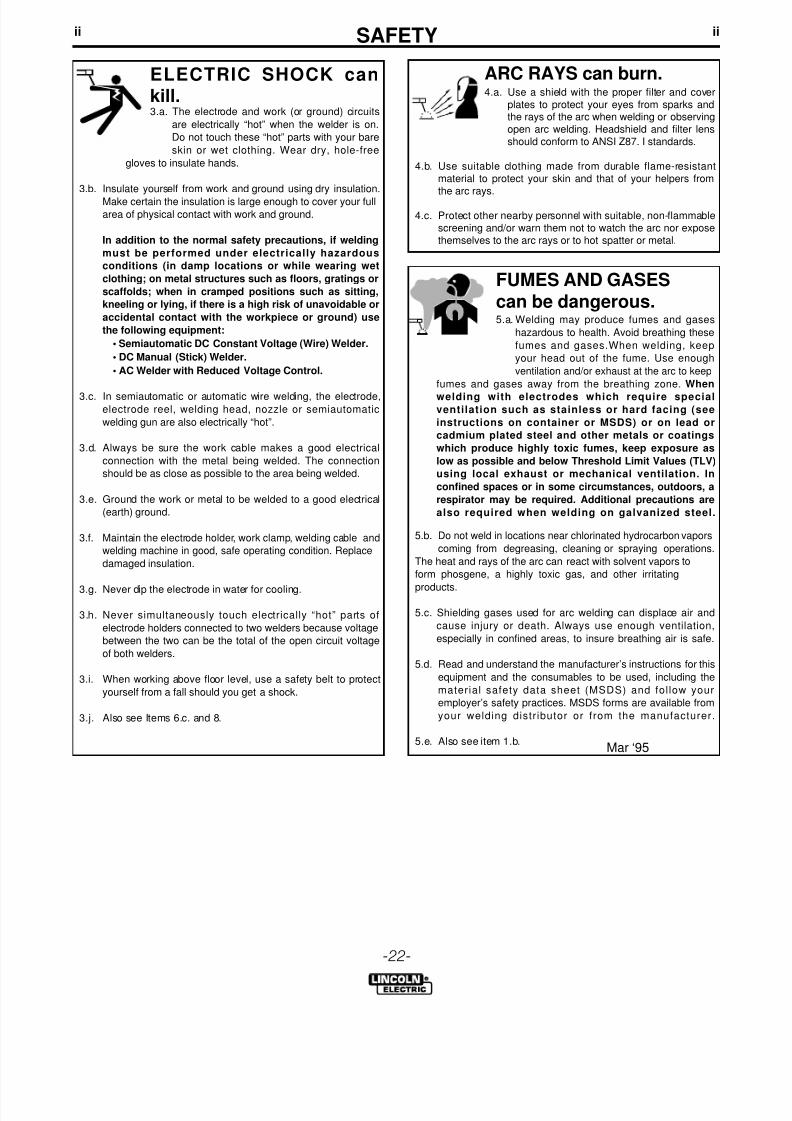
iiSAFETYii
ARC RAYS can burn.4.a. Use a shield with the proper filter and cover
plates to protect your eyes from sparks andthe rays of the arc when welding or observingopen arc welding. Headshield and filter lensshould conform to ANSI Z87. I standards.
4.b. Use suitable clothing made from durable flame-resistantmaterial to protect your skin and that of your helpers from
the arc rays.
4.c. Protect other nearby personnel with suitable, non-flammablescreening and/or warn them not to watch the arc nor exposethemselves to the arc rays or to hot spatter or metal.
ELECTRIC SHOCK cankill.3.a. The electrode and work (or ground) circuits
are electrically “hot” when the welder is on.
Do not touch these “hot” parts with your bare
skin or wet clothing. Wear dry, hole-free
gloves to insulate hands.
3.b. Insulate yourself from work and ground using dry insulation.
Make certain the insulation is large enough to cover your full
area of physical contact with work and ground.
In addition to the normal safety precautions, if welding
must be performed under electrically hazardous
conditions (in damp locations or while wearing wet
clothing; on metal structures such as floors, gratings or
scaffolds; when in cramped positions such as sitting,
kneeling or lying, if there is a high risk of unavoidable or
accidental contact with the workpiece or ground) use
the following equipment:
• Semiautomatic DC Constant Voltage (Wire) Welder.
• DC Manual (Stick) Welder.
• AC Welder with Reduced Voltage Control.
3.c. In semiautomatic or automatic wire welding, the electrode,electrode reel, welding head, nozzle or semiautomatic
welding gun are also electrically “hot”.
3.d. Always be sure the work cable makes a good electrical
connection with the metal being welded. The connection
should be as close as possible to the area being welded.
3.e. Ground the work or metal to be welded to a good electrical
(earth) ground.
3.f. Maintain the electrode holder, work clamp, welding cable and
welding machine in good, safe operating condition. Replace
damaged insulation.
3.g. Never dip the electrode in water for cooling.
3.h. Never simultaneously touch electrically “hot” parts of
electrode holders connected to two welders because voltage
between the two can be the total of the open circuit voltage
of both welders.
3.i. When working above floor level, use a safety belt to protect
yourself from a fall should you get a shock.
3.j. Also see Items 6.c. and 8.
FUMES AND GASEScan be dangerous.5.a. Welding may produce fumes and gases
hazardous to health. Avoid breathing these
fumes and gases.When welding, keep
your head out of the fume. Use enough
ventilation and/or exhaust at the arc to keep
fumes and gases away from the breathing zone. When
welding with electrodes which require special
ventilation such as stainless or hard facing (see
instructions on container or MSDS) or on lead or
cadmium plated steel and other metals or coatings
which produce highly toxic fumes, keep exposure as
low as possible and below Threshold Limit Values (TLV)
using local exhaust or mechanical ventilation. In
confined spaces or in some circumstances, outdoors, a
respirator may be required. Additional precautions are
also required when welding on galvanized steel.
5.b. Do not weld in locations near chlorinated hydrocarbon vapors
coming from degreasing, cleaning or spraying operations.
The heat and rays of the arc can react with solvent vapors to
form phosgene, a highly toxic gas, and other irritating
products.
5.c. Shielding gases used for arc welding can displace air and
cause injury or death. Always use enough ventilation,
especially in confined areas, to insure breathing air is safe.
5.d. Read and understand the manufacturer’s instructions for this
equipment and the consumables to be used, including the
material safety data sheet (MSDS) and follow your
employer’s safety practices. MSDS forms are available from
your welding distr ibutor or from the manufacturer.
5.e. Also see item 1.b.Mar ‘95
-22-
8/10/2019 Aluminium Mig Welding Guide.pdf
http://slidepdf.com/reader/full/aluminium-mig-welding-guidepdf 23/28
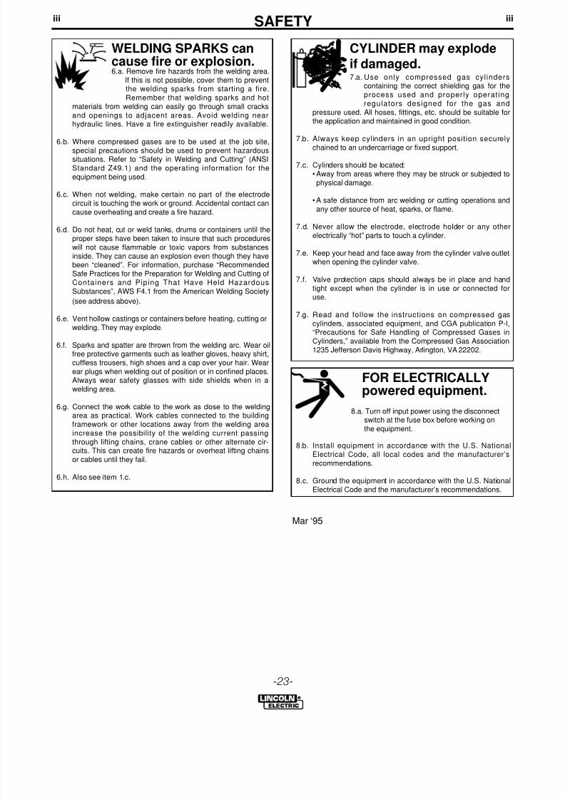
FOR ELECTRICALLYpowered equipment.
8.a. Turn off input power using the disconnect
switch at the fuse box before working onthe equipment.
8.b. Install equipment in accordance with the U.S. NationalElectrical Code, all local codes and the manufacturer’srecommendations.
8.c. Ground the equipment in accordance with the U.S. NationalElectrical Code and the manufacturer’s recommendations.
CYLINDER may explodeif damaged.7.a. Use only compressed gas cylinders
containing the correct shielding gas for theprocess used and properly operatingregulators designed for the gas and
pressure used. All hoses, fittings, etc. should be suitable forthe application and maintained in good condition.
7.b. Always keep cylinders in an upright position securelychained to an undercarriage or fixed support.
7.c. Cylinders should be located:• Away from areas where they may be struck or subjected tophysical damage.
• A safe distance from arc welding or cutting operations andany other source of heat, sparks, or flame.
7.d. Never allow the electrode, electrode holder or any otherelectrically “hot” parts to touch a cylinder.
7.e. Keep your head and face away from the cylinder valve outletwhen opening the cylinder valve.
7.f. Valve protection caps should always be in place and handtight except when the cylinder is in use or connected foruse.
7.g. Read and follow the instructions on compressed gascylinders, associated equipment, and CGA publication P-l,“Precautions for Safe Handling of Compressed Gases inCylinders,” available from the Compressed Gas Association1235 Jefferson Davis Highway, Arlington, VA 22202.
iiiSAFETYiii
Mar ‘95
WELDING SPARKS cancause fire or explosion.6.a. Remove fire hazards from the welding area.
If this is not possible, cover them to preventthe welding sparks from starting a fire.Remember that welding sparks and hot
materials from welding can easily go through small cracksand openings to adjacent areas. Avoid welding nearhydraulic lines. Have a fire extinguisher readily available.
6.b. Where compressed gases are to be used at the job site,special precautions should be used to prevent hazardoussituations. Refer to “Safety in Welding and Cutting” (ANSIStandard Z49.1) and the operating information for theequipment being used.
6.c. When not welding, make certain no part of the electrodecircuit is touching the work or ground. Accidental contact cancause overheating and create a fire hazard.
6.d. Do not heat, cut or weld tanks, drums or containers until theproper steps have been taken to insure that such procedureswill not cause flammable or toxic vapors from substancesinside. They can cause an explosion even though they havebeen “cleaned”. For information, purchase “RecommendedSafe Practices for the Preparation for Welding and Cutting of
Containers and Piping That Have Held HazardousSubstances”, AWS F4.1 from the American Welding Society
(see address above).
6.e. Vent hollow castings or containers before heating, cutting orwelding. They may explode.
6.f. Sparks and spatter are thrown from the welding arc. Wear oilfree protective garments such as leather gloves, heavy shirt,cuffless trousers, high shoes and a cap over your hair. Wearear plugs when welding out of position or in confined places.Always wear safety glasses with side shields when in awelding area.
6.g. Connect the work cable to the work as close to the weldingarea as practical. Work cables connected to the buildingframework or other locations away from the welding areaincrease the possibility of the welding current passingthrough lifting chains, crane cables or other alternate cir-cuits. This can create fire hazards or overheat lifting chainsor cables until they fail.
6.h. Also see item 1.c.
-23-
8/10/2019 Aluminium Mig Welding Guide.pdf
http://slidepdf.com/reader/full/aluminium-mig-welding-guidepdf 24/28
ivSAFETYiv
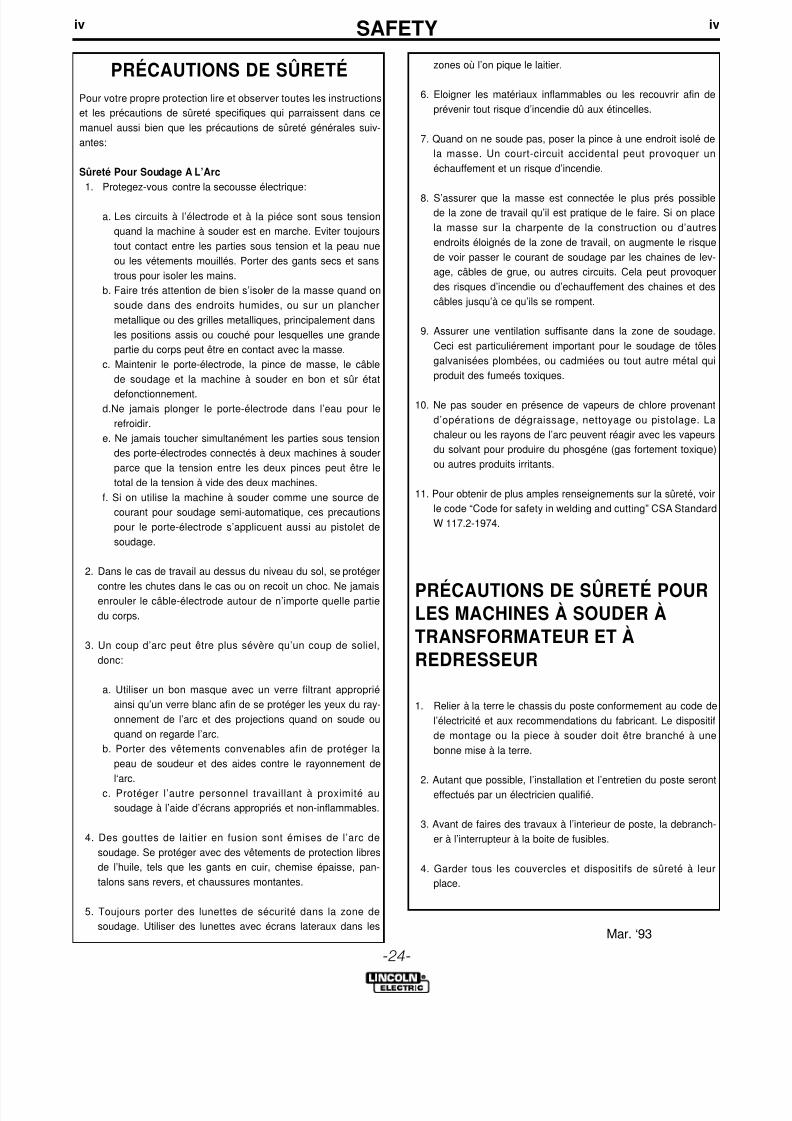
PRÉCAUTIONS DE SÛRETÉPour votre propre protection lire et observer toutes les instructions
et les précautions de sûreté specifiques qui parraissent dans ce
manuel aussi bien que les précautions de sûreté générales suiv-
antes:
Sûreté Pour Soudage A L’Arc1. Protegez-vous contre la secousse électrique:
a. Les circuits à l’électrode et à la piéce sont sous tension
quand la machine à souder est en marche. Eviter toujours
tout contact entre les parties sous tension et la peau nue
ou les vétements mouillés. Porter des gants secs et sans
trous pour isoler les mains.
b. Faire trés attention de bien s’isoler de la masse quand on
soude dans des endroits humides, ou sur un plancher
metallique ou des grilles metalliques, principalement dans
les positions assis ou couché pour lesquelles une grande
partie du corps peut être en contact avec la masse.
c. Maintenir le porte-électrode, la pince de masse, le câble
de soudage et la machine à souder en bon et sûr état
defonctionnement.d.Ne jamais plonger le porte-électrode dans l’eau pour le
refroidir.
e. Ne jamais toucher simultanément les parties sous tension
des porte-électrodes connectés à deux machines à souder
parce que la tension entre les deux pinces peut être le
total de la tension à vide des deux machines.
f. Si on utilise la machine à souder comme une source de
courant pour soudage semi-automatique, ces precautions
pour le porte-électrode s’applicuent aussi au pistolet de
soudage.
2. Dans le cas de travail au dessus du niveau du sol, se protéger
contre les chutes dans le cas ou on recoit un choc. Ne jamaisenrouler le câble-électrode autour de n’importe quelle partie
du corps.
3. Un coup d’arc peut être plus sévère qu’un coup de soliel,
donc:
a. Utiliser un bon masque avec un verre filtrant approprié
ainsi qu’un verre blanc afin de se protéger les yeux du ray-
onnement de l’arc et des projections quand on soude ou
quand on regarde l’arc.
b. Porter des vêtements convenables afin de protéger la
peau de soudeur et des aides contre le rayonnement de
l‘arc.
c. Protéger l’autre personnel travaillant à proximité au
soudage à l’aide d’écrans appropriés et non-inflammables.
4. Des gouttes de laitier en fusion sont émises de l’arc de
soudage. Se protéger avec des vêtements de protection libres
de l’huile, tels que les gants en cuir, chemise épaisse, pan-
talons sans revers, et chaussures montantes.
5. Toujours porter des lunettes de sécurité dans la zone de
soudage. Utiliser des lunettes avec écrans lateraux dans les
zones où l’on pique le laitier.
6. Eloigner les matériaux inflammables ou les recouvrir afin de
prévenir tout risque d’incendie dû aux étincelles.
7. Quand on ne soude pas, poser la pince à une endroit isolé de
la masse. Un court-circuit accidental peut provoquer un
échauffement et un risque d’incendie.
8. S’assurer que la masse est connectée le plus prés possiblede la zone de travail qu’il est pratique de le faire. Si on place
la masse sur la charpente de la construction ou d’autres
endroits éloignés de la zone de travail, on augmente le risque
de voir passer le courant de soudage par les chaines de lev-
age, câbles de grue, ou autres circuits. Cela peut provoquer
des risques d’incendie ou d’echauffement des chaines et des
câbles jusqu’à ce qu’ils se rompent.
9. Assurer une ventilation suffisante dans la zone de soudage.
Ceci est particuliérement important pour le soudage de tôles
galvanisées plombées, ou cadmiées ou tout autre métal qui
produit des fumeés toxiques.
10. Ne pas souder en présence de vapeurs de chlore provenant
d’opérations de dégraissage, nettoyage ou pistolage. La
chaleur ou les rayons de l’arc peuvent réagir avec les vapeurs
du solvant pour produire du phosgéne (gas fortement toxique)
ou autres produits irritants.
11. Pour obtenir de plus amples renseignements sur la sûreté, voir
le code “Code for safety in welding and cutting” CSA Standard
W 117.2-1974.
PRÉCAUTIONS DE SÛRETÉ POURLES MACHINES À SOUDER ÀTRANSFORMATEUR ET ÀREDRESSEUR
1. Relier à la terre le chassis du poste conformement au code de
l’électricité et aux recommendations du fabricant. Le dispositif
de montage ou la piece à souder doit être branché à une
bonne mise à la terre.
2. Autant que possible, I’installation et l’entretien du poste seront
effectués par un électricien qualifié.
3. Avant de faires des travaux à l’interieur de poste, la debranch-
er à l’interrupteur à la boite de fusibles.
4. Garder tous les couvercles et dispositifs de sûreté à leur
place.
Mar. ‘93
-24-

8/10/2019 Aluminium Mig Welding Guide.pdf
http://slidepdf.com/reader/full/aluminium-mig-welding-guidepdf 25/28
-25-

8/10/2019 Aluminium Mig Welding Guide.pdf
http://slidepdf.com/reader/full/aluminium-mig-welding-guidepdf 26/28
-26-

8/10/2019 Aluminium Mig Welding Guide.pdf
http://slidepdf.com/reader/full/aluminium-mig-welding-guidepdf 27/28
-27-
Customer Assistance Policy
The business of The Lincoln Electric Company is manufacturing and selling high quality welding equipment, consumables, and cutting equipmenOur challenge is to meet the needs of our customers and to exceed their expectations. On occasion, purchasers may ask Lincoln Electric foradvice or information about their use of our products. We respond to our customers based on the best information in our possession at that timeLincoln Electric is not in a position to warrant or guarantee such advice, and assumes no l iability, with respect to such information of advice. Weexpressly disclaim any warranty of any kind, including any warranty of fitness for any customer’s particular purpose, with respect to such information or advice. As a matter of practical consideration, we also cannot assume any responsibility for updating or correcting any such information oadvice once it has been given, nor does the provision of information or advice create, expand or alter any warranty with respect to the sale of ourproducts.
Lincoln Electric is a responsive manufacturer, but the selection and use of specific products sold by Lincoln Electric is solely within the control of,and remains the sole responsibility of the customer. Many variables beyond the control of Lincoln Electric affect the results obtained in applyingthis type of fabrication methods and service requirements.
8/10/2019 Aluminium Mig Welding Guide.pdf
http://slidepdf.com/reader/full/aluminium-mig-welding-guidepdf 28/28
DISTRIBUTED BY:
LINCOLN NORTH AMERICADISTRICT SALES OFFICES
LATIN AMERICA Miami, Florida U.S.A.
Phone: (305) 888-3203
EUROPE
The Netherlands
Phone: 31 24 3522 911
RUSSIA, AFRICA & MIDDLE EAST
Cleveland, Ohio U.S.A.
Phone: (216) 481-8100
ASIA PACIFIC
Singapore
Phone: 65 276 0878
LINCOLN INTERNATIONAL HEADQUARTERS
HARRIS CALORIFIC DIVISION
2345 Murphy Blvd., Gainesville, Georgia 30504 U.S.A.Phone: 1-800-241-0804 • Fax: (770) 535-0544 • Web Site: www.harriscal.com
U.S.A.
ALABAMA BIRMINGHAM 35124-1156(205) 988-8232MOBILE 36582-5209(251) 443-6524
ALASKA Contact SEATTLEDistrict Office
(206) 575-2456 ARIZONA
PHOENIX 85260-1768(480) 348-2004
ARKANSASLITTLE ROCK 72032-4371(501) 764-0480
CALIFORNIA FRESNO 93722-3949(559) 276-0110LOS ANGELES 90670-2936(562) 906-7700SACRAMENTO 95677-4729(916) 630-1885SAN DIEGO 92108-3911(619) 208-9001SAN FRANCISCO 94550-9657(925) 443-9353
COLORADO
DENVER 80112-5115(303) 742-8887
CONNECTICUTNORTH HAVEN 06238-1090(860) 742-8887
WASHINGTON DCHERNDON, VA 20170-5227(703) 904-7735
FLORIDA JACKSONVILLE 32216-4634(904) 642-3177MIAMI 33178-1175(305) 888-3203ORLANDO 32714-1974(407) 788-8557TAMPA 33594-6387(770) 475-0955
GEORGIA ATLANTA 30076-4914
(770) 475-0955SAVANNAH 31324-5180(912) 727-4286
HAWAIISee SEATTLEDistrict Office(206) 575-2456
IDAHOBOISE 83616-6646(208) 938-2302
ILLINOISCHICAGO 60527-5629(630) 920-1500
PEORIA 60527-5629(630) 920-1500
INDIANA EVANSVILLE 47630(812) 842-2775FT. WAYNE 46825-5547(219) 484-4422SOUTH BEND 46561-9160(219) 674-5523INDIANAPOLIS 46038-9459(317) 845-8445
IOWA CEDAR RAPIDS 52402-3160(319) 362-6804DAVENPORT 52806-1344(563) 386-6522DES MOINES 50265-6218(515) 224-4121
KANSAS
KANSAS CITY 66214-1625(913) 894-0888WICHITA 67037-9614(316) 788-7367
KENTUCKY LOUISVILLE 47112-7025(502) 727-7335
LOUISIANA BATON ROUGE 70808-3150(225) 922-5151LAFAYETTE 70507-3126(337) 886-1090SHREVEPORT 71108-2521(318) 869-3531
MARYLANDBALTIMORE 21050-3067(443) 831-0416
MASSACHUSETTSBOSTON 02452-8405
(781) 899-2010
MICHIGANDETROIT 48034-4005(248) 353-9680FLUSHING 48433-1855(810) 487-1310GRAND RAPIDS 49512-3924(616) 942-8780
MINNESOTA MINNEAPOLIS 55447-5435(612) 551-1990
MISSISSIPPIJACKSON 39212-9635(601) 372-7679
MISSOURIKANSAS CITY (KS) 66214-1625(913) 894-0888ST. LOUIS 63146-3572(314) 993-5465SPRINGFIELD 65804(417) 823-0574
MONTANA Contact SEATTLEDistrict Office(206) 575-2456
NEBRASKA LINCOLN 68521-4806(402) 474-5697OMAHA 68046-2826(402) 339-1809
NEW JERSEY EDISON 08837-3939(732) 225-2000
NEW MEXICO ALBUQUERQUE 87008(505) 286-4801
NEW YORK ALBANY(315) 432-0281BUFFALO(315) 432-0281NEW YORK CITY (888) 269-6755SYRACUSE 13057-1040(315) 432-0281
NORTH CAROLINA CHARLOTTE 28273-6200(704) 588-3251RALEIGH 27604-8456
(919) 231-5855
OHIO AKRON 44236-4680(330) 342-8009CINCINNATI 45242-3706(513) 554-4440CLEVELAND 44143-1433(216) 289-4160COLUMBUS 43221-4073(614) 488-7913DAYTON 45458(937) 885-6964
TOLEDO 43528-9483(419) 867-7284
OKLAHOMA OKLAHOMA CITY 73119-2416(405) 686-1170TULSA 74146-1622(918) 622-9353
OREGONPORTLAND 97220-6800(503) 528-0553
PENNSYLVANIA ERIE 16506-2979(814) 835-3531JOHNSTOWN 15905-2506(814) 535-5895PHILADELPHIA 19008-4310(610) 543-9462PITTSBURGH 15275-1002(412) 787-7733
YORK 17404-1144(717) 764-6565
SOUTH CAROLINA GREENVILLE 29681-4724(864) 967-4157COLUMBIA 29209(803) 783-2851
SOUTH DAKOTA SIOUX FALLS 57108-2609(605) 339-6522
TENNESSEEKNOXVILLE 37923-4506(865) 693-5513MEMPHIS 38115-5946(901) 363-1075NASHVILLE 37027(615) 236-1144TRI-CITIES 37601-3411(423) 928-6047
TEXASDALLAS 76051-7602(817) 329-9353HOUSTON 77060-3143(281) 847-9444SAN ANTONIO 78133-3502(830) 964-2421
UTAHMIDVALE 84047-3759(801) 233-9353
VIRGINIA HERNDON 20170-5227Washington, D.C.(703) 904-7735ROANOKE(703) 904-7735WILLIAMSBURG 23602-7048(757) 870-5508
WASHINGTONSEATTLE 98188-7615(206) 575-2456SPOKANE 99005-9637(509) 468-2770
WEST VIRGINIA CHARLESTON 25526-9796(304) 757-9862
WISCONSINGREEN BAY 54302-1829(920) 435-1012MILWAUKEE 53186-0403(262) 650-9364
CANADA
ALBERTA CALGARY T2H 2M3
(403) 253-9600EDMONTON T6H 2K1(403) 436-7385WINNIPEG R3N 0C7(204) 488-6398
BRITISH COLUMBIA VANCOUVER V3B 7A2(604) 844-5209
MARITIMESNOVA SCOTIA B2X 3N2(902) 434-2725
MANITOBA WINNIPEG R3N 0C7(204) 488-6398
ONTARIOTORONTO M4G 2B9(416) 421-2600
QUEBECMONTREAL J5Y 2G3
(514) 654-3121