aluminum structures
TRANSCRIPT
ALUMINUMSTRUCTURES
A Guide to Their Specificationsand Design
Second Edition
J. Randolph KissellRobert L. FerryThe TGB Partnership
JOHN WILEY & SONS, INC.
This book is printed on acid-free paper.��
Copyright � 2002 by John Wiley & Sons, Inc., New York. Allrights reserved.
Published simultaneously in Canada.
No part of this publication may be reproduced, stored in a retrievalsystem or transmitted in any form or by any means, electronic,mechanical, photocopying, recording, scanning or otherwise, exceptas permitted under Sections 107 or 108 of the 1976 United StatesCopyright Act, without either the prior written permission of thePublisher, or authorization through payment of the appropriate per-copy fee to the Copyright Clearance Center, 222 Rosewood Drive,Danvers, MA 01923, (978) 750-8400, fax (978) 750-4744. Requeststo the Publisher for permission should be addressed to thePermissions Department, John Wiley & Sons, Inc., 605 ThirdAvenue, New York, NY 10158-0012, (212) 850-6011, fax (212)850-6008, E-Mail: [email protected].
This publication is designed to provide accurate and authoritativeinformation in regard to the subject matter covered. It is sold withthe understanding that the publisher is not engaged in renderingprofessional services. If professional advice or other expertassistance is required, the services of a competent professionalperson should be sought.
Wiley also publishes its books in a variety of electronic formats.Some content that appears in print may not be available inelectronic books. For more information about Wiley products, visitour web site at www.wiley.com.
Library of Congress Cataloging-in-Publication Data:
ISBN: 0-471-01965-8
Printed in the United States of America
10 9 8 7 6 5 4 3 2 1
iii
CONTENTS
Preface to the First Edition ix
Preface to the Second Edition xi
PART I INTRODUCTION 1
1 What’s in This Book? 3
2 What Is Aluminum? 5
2.1 Metal in Construction 52.2 Many Metals from Which to Choose 72.3 When to Choose Aluminum 8
2.3.1 Introduction 82.3.2 Factors to Consider 11
2.4 Aluminum Alloys and Tempers 132.4.1 Introduction 132.4.2 Wrought Alloys 132.4.3 Tempers 17
2.5 Structural Applications of Aluminum 232.5.1 Background 232.5.2 Building and Construction
Applications 24
3 Working with Aluminum 31
3.1 Product Forms 313.1.1 Extrusions 313.1.2 Sheet and Plate 563.1.3 Forgings 673.1.4 Castings 693.1.5 Prefabricated Products 74
iv CONTENTS
3.2 Coatings and Finishes 863.2.1 Mill Finish 873.2.2 Anodized Finishes 873.2.3 Painted Finishes 913.2.4 Mechanical Finishes 933.2.5 Cladding 933.2.6 Roofing and Siding Finishes 94
3.3 Erection 94
PART II STRUCTURAL BEHAVIOR OF ALUMINUM 97
4 Material Properties for Design 99
4.1 Minimum and Typical Properties 994.2 Strengths 1004.3 Modulus of Elasticity (E), Shear Modulus (G), and
Poisson’s Ratio (�) 1014.4 Fracture Properties 1034.5 The Effect of Welding on Mechanical
Properties 1054.6 The Effect of Temperature on Aluminum
Properties 1064.7 Fire Resistance 1084.8 Hardness 1094.9 Physical Properties 1094.10 Aluminum Material Specifications 1104.11 Alloy Identification 1134.12 Certification Documentation 113
5 Explanation of the Aluminum Specification 115
5.1 Tension Members 1155.1.1 Tensile Strength 1165.1.2 Net Area 1225.1.3 Effective Net Area 1245.1.4 Maximum Slenderness Ratios for Tension
Members 1255.2 Compression Members 126
5.2.1 Overall Buckling (Columns) 1295.2.2 Local Buckling (Components of
Columns) 1455.3 Members in Bending 171
5.3.1 Bending Yielding and Fracture 172
CONTENTS v
5.3.2 Bending Buckling 1755.3.3 Bending Shear 199
5.4 Torsion 2045.4.1 St. Venant Torsion 2065.4.2 Warping Torsion 2085.4.3 A Final Note 210
5.5 Combined Stresses 2105.5.1 Combined Axial Compression and
Bending 2105.5.2 Combined Tension and Bending 2135.5.3 Combined Shear, Compression, and
Bending 2135.5.4 Biaxial and Triaxial Stresses 214
6 Orientation to the Aluminum Specification 217
6.1 Background 2176.2 The Aluminum Design Manual 2196.3 Types of Structures Addressed by the Aluminum
Specification 2236.4 Significant Figures and the Aluminum
Specification 224
PART III DESIGN CHECKS FOR STRUCTURALCOMPONENTS 227
7 Structural Members 229
7.1 Tension Member Design Procedure 2297.1.1 Net Effective Area 2307.1.2 Allowable Stress 2307.1.3 Tensile Capacity 231
7.2 Compression Member Design Procedure 2317.2.1 Overall Column Slenderness Ratio 2327.2.2 Slenderness Ratio of Cross-Sectional
Elements 2337.2.3 Allowable Column Stress of Typical
Shapes 2337.2.4 Summary of Allowable Column
Stress 2397.3 Bending Member Design Procedure 239
7.3.1 Bending Tension 2417.3.2 Bending Compression 241
vi CONTENTS
7.3.3 Shear 2477.4 Combined Stresses Design Procedure 247
7.4.1 Combined Axial Compression andBending 247
7.4.2 Combined Tension and Bending 2487.4.3 Combined Shear, Compression, and
Bending 249
8 Connections 251
8.1 Mechanical Connections 2518.1.1 Introduction 2518.1.2 Types of Fasteners 2538.1.3 Fastener Material Selection 2598.1.4 Fastener Mechanical Properties 2618.1.5 Types of Loads on Fasteners 2648.1.6 Types of Bolted Connections 2658.1.7 Holes 2678.1.8 Failure Modes for Mechanically Fastened
Joints 2688.1.9 Tensile Loads on Fasteners 2708.1.10 Shear Loads on Fasteners 2728.1.11 Combined Shear and Tension on
Bolts 2768.1.12 Bearing Strength and Edge Distance 2778.1.13 Tension Strength of Connected Parts 2788.1.14 Shear Rupture 2788.1.15 Minimum Spacing and Edge
Distance 2818.1.16 Maximum Edge Distance and
Spacing 2818.1.17 Screw Connections 2848.1.18 Minimum Requirements for
Connections 2888.2 Welded Connections 289
8.2.1 Aluminum Welding Processes 2898.2.2 Selecting a Filler Alloy 2918.2.3 Types of Welds 2928.2.4 Comparing Aluminum and Steel Fillet
Weld Safety Factors 3008.2.5 Weld Fabrication 3008.2.6 Weld Quality Assurance 304
CONTENTS vii
9 Special Topics 307
9.1 Welded Members 3079.1.1 What Welding Does to Aluminum 3079.1.2 Types of Welded Members 3109.1.3 Welded Tension Members 3119.1.4 Welded Compression Members 3159.1.5 Post-Weld Heat Treatment 318
9.2 Fatigue 3199.2.1 Fatigue—What Is It Again? 3209.2.2 Fatigue Design: The Ground Rules 3229.2.3 Variable Amplitude Fatigue Design 3269.2.4 Aluminum Versus Steel in Fatigue 3279.2.5 Other Factors in Fatigue 3289.2.6 A Final Word 329
9.3 Recent Developments in Aluminum Structures 3299.3.1 Friction Stir Welding 3299.3.2 Alloy 6082 3309.3.3 Aluminum-Lithium Alloys 3309.3.4 The New Aluminum Automotive
Alloys 3329.3.5 Aluminum Metal Matrix Composites 333
PART IV DESIGN OF STRUCTURAL SYSTEMS 335
10 Structural Systems Built with Aluminum 337
10.1 Cold-Formed Aluminum Construction 33710.1.1 Building Sheathing 33710.1.2 Cold-Formed Aluminum Design 34310.1.3 Elastically Supported Flanges 350
10.2 Aluminum Frames 35110.2.1 System Description 35110.2.2 Model for Analysis 35310.2.3 Getting Started 35410.2.4 Analyzing the Dome 35810.2.5 Design Checks 362
10.3 Aluminum Composite Members 37310.3.1 Composite Beams 37410.3.2 Thermal Stresses 37510.3.3 Dissimilar Material Contact 378
10.4 Aluminum Pressure Piping 379

viii CONTENTS
10.5 Aluminum Plate Structures 38310.5.1 Stiffeners 38310.5.2 Compressive Strengths 38510.5.3 Fabrication 386
PART V LOAD AND RESISTANCE FACTOR DESIGN 387
11 Load and Resistance Factor Design 389
11.1 New Tricks for Old Dogs 38911.2 LRFD—The Concept 39011.3 What’s New: Load Factors 39111.4 What’s the Same 39211.5 When Do I Use LRFD? 39311.6 Which Way Lets Me Use Less Metal? 39411.7 The General Expression for Comparing LRFD to
ASD 39711.8 How They Came Up with the LRFD
Specification 39911.9 How Do I Actually Start Using LRFD? 40511.10 The Future of the ASD and LRFD Aluminum
Specifications 406
Appendixes
A. Pre-1954 Wrought Alloy Designations 407B. Section Properties of Common Aluminum Shapes 409C. Minimum Mechanical Properties of Aluminum Alloys 413D. Allowable Stresses for Elements of Common Aluminum
Shapes 425E. LRFD Design Stresses for Elements of Common Aluminum
Shapes 429F. Column Buckling Allowable Stress 433G. Summary of the Aluminum Specification Design Provisions
for Columns and Beams 435H. Cross Reference to the Aluminum Specification 437I. LRFD Design Stresses for Various Alloys 441J. Other Aluminum Structural Design Specifications 463
K. Buckling Constants 469L. Metric Conversions 475
M. Statistics 477N. Technical Organizations 495
Glossary 503
References 519
Index 527
ix
PREFACE TO THEFIRST EDITION
The purpose of this book is to enlighten humanity and contribute to the gen-eral betterment of this orb that we call home. Failing that, we will settle forgiving engineers enough guidance in the use of aluminum that they will feelconfident designing with it. The Aluminum Association, an industry associ-ation of aluminum producers, publishes the Specifications for AluminumStructures (hereafter called the Aluminum Specifications), which are the gen-erally accepted criteria for the design of aluminum structures. Our book iskeyed to the sixth edition of the Aluminum Specifications, and readers shouldhave access to it.
Structural engineering may be regarded as the practice of analyzing anddesigning structures. The analysis process resolves the loads applied to thestructure into the resulting forces and moments in the components of thestructure. Structural design is, then, the sizing of the structure’s componentsto safely sustain these forces and moments. Academic curricula typically trainstudents in structural analysis, as well as in the design methods appropriateto common materials of construction (i.e., steel, concrete, and perhaps timber),and many excellent texts on these subjects are available. We assume that thereader is already well versed in structural analysis and acquainted with steeldesign. Our objective is to expand readers’ design capability beyond steel,and to present aluminum as another material of construction.
While this text is keyed to the Aluminum Specifications, it is also organizedto parallel steel design practice. We compare the requirements of the Alu-minum Specifications to the provisions for the design of steel structures foundin the American Institute of Steel Construction (AISC) Manual of Steel Con-struction. Those design requirements and considerations that are particular toaluminum, then, are presented in the context of the steel design backgroundthat we assume on the part of the reader.
In addition to bridging the gap between the familiar old state of steel andthe exciting new realm of aluminum, we also seek to bridge the gap betweenthe theoretical and the real worlds. We recognize that one of the greatestdifficulties in the transition from student to practitioner is knowing how to

x PREFACE
apply the design methods in ‘‘the book’’ to real-life problems. Whether thatbook is a text or an industry specification, it often seems that the problem athand does not neatly fit into any of the categories given. We include a step-by-step design process for real-world applications. If our steps do not sparereaders from a 12-step program, then their problems are beyond the scope ofthis text.
J. RANDOLPH KISSELL
ROBERT L. FERRY
The TGB PartnershipHillsborough, North Carolina
xi
PREFACE TO THESECOND EDITION
We were frankly surprised by the reaction to the first edition of this book.While it never threatened to reach the New York Times best seller list, thefavorable comments were more numerous and heartfelt than we had expected.When a reader wrote that ‘‘you will be pleased to know that your book israpidly becoming dog-eared as it is one of the most popular books in ourlibrary,’’ we knew we had achieved our goal. What may have been the mostsurprising was the international notice the book received, including a Japanesetranslation and very favorable European reviews. All this almost made up forthe work it took to write it.
Once we’d milked the acclaim for all we could, it was time to think abouta second edition. The Aluminum Association forced our hand when it revisedthe Specification for Aluminum Structures in the 2000 edition of the AluminumDesign Manual. Since this book is a guide to the Specification, an update wasdue. The changes to the Specification are more than cosmetic, such as chang-ing the title to the singular ‘‘Specification.’’ They include changes to tensionlimit states, design compressive strengths for yielding, design bearing stresses,slip-critical connections, screw pull-out strengths, and others, as well as met-rication of mechanical properties. We’ve revised our text accordingly andmetricated it, too, although we haven’t been pedantic about metrication inorder to preserve readability. We’ve also added the benefit of what is, wehope, additional wisdom gained from experience since the first edition. Sincethe Specification continues to be a living document, we’re dealing with amoving target, but that keeps life interesting.
We welcome readers’ comments—this time with slightly less trepidationthan before. It’s also easier now since this time we have an e-mail address:[email protected]. Thanks for your interest in aluminum and our book.
J. RANDOLPH KISSELL
ROBERT L. FERRY
The TGB PartnershipHillsborough, North Carolina


PART IIntroduction
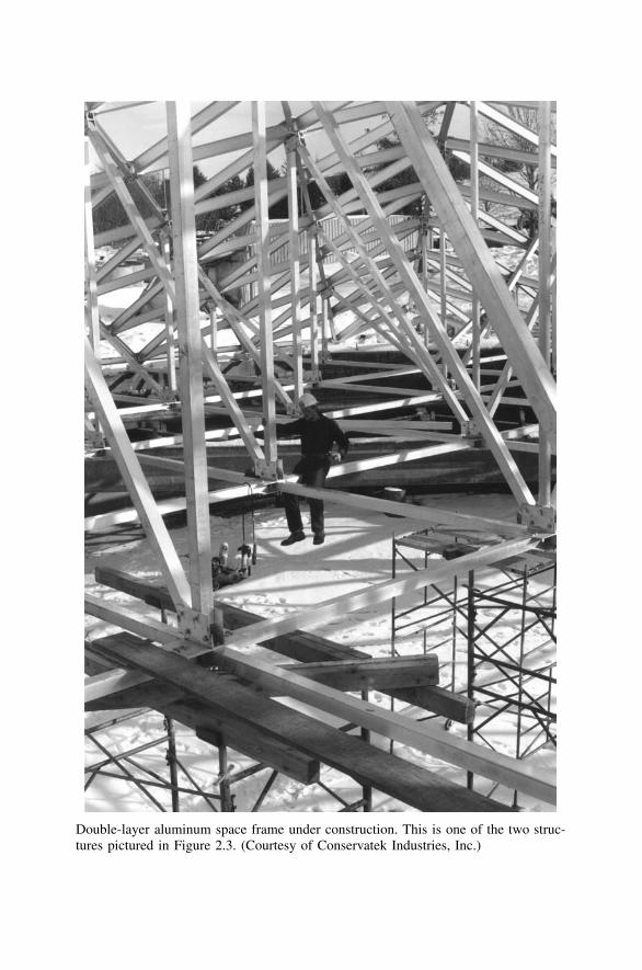
Double-layer aluminum space frame under construction. This is one of the two struc-tures pictured in Figure 2.3. (Courtesy of Conservatek Industries, Inc.)
3
1 What’s in This Book?
Our book is about the use of aluminum as a material of construction forstructural components.
Our major themes are:
• The suitability of aluminum as a structural material,• How to design aluminum structural components in accordance with the
Aluminum Association’s Specification for Aluminum Structures,• How to apply the design methods to actual structures.
We begin by introducing you to aluminum, and we hope that by the endof Part I you are sufficiently well acquainted to be ready to get serious aboutthe relationship. In Part II we explain the design requirements of the 2000edition of the Specification for Aluminum Structures (hereafter called the Alu-minum Specification), published by the Aluminum Association in its Alumi-num Design Manual (4). Those of you who can’t wait to plug and chug maywant to jump right ahead to Part III, and refer back to Part II only when youwant to know ‘‘Where did that come from?’’
We assume that you have already had ample exposure to methods of loaddetermination and structural analysis, so we do not replow that ground. Wedo, however, include in Part II a discussion on local buckling since this is alimit state (i.e., failure mode to you old-timers) that you may have beensheltered from if your design experience has been primarily with hot-rolledsteel.
As we discussed in the Preface, we have keyed the discussion of designrequirements to the Aluminum Specification. In Part II we compare thesedesign provisions to the more familiar requirements for steel buildings pub-lished by the American Institute of Steel Construction (AISC) in the Speci-fication for Structural Steel Buildings (hereafter called the Steel Specification)(38, 39). The Aluminum Specification is primarily intended for building struc-tures; thus, we focus on these applications.
Throughout the book we give attention to those features of aluminum thatdifferentiate it from other structural materials, particularly steel. Perhaps themost significant feature that distinguishes aluminum from steel is its extrud-ability. Extruding is the process of forming a product by pushing it throughan opening called a die. The cross section of the resulting product is deter-mined by the shape of the die. You may simply prepare a drawing of the
4 WHAT’S IN THIS BOOK?
cross section that you desire for a certain application, then have the mill makea die for producing that shape. This is not the case for steel.
We know from personal experience that while custom extrusions enabledesigners to exercise a great deal of creativity, the process of sizing a uniqueshape can be very tedious. When designing with steel, engineers often restricttheir choices to those shapes listed in tables of compact sections, where thesection properties and dimensions are all provided, and the slenderness of thecross-sectional elements have already been checked to confirm that they arenot governed by local buckling. While this approach may be safe, it is notvery creative. When we create our own shape, however, we assume respon-sibility for determining its section properties and checking the slenderness ofthe cross-sectional elements. Furthermore, we may find that our new sectionis not compact, and we must then determine the local buckling stress limits.As mentioned previously, Part II includes a comprehensive explanation of thebehavior of these slender (light gauge) shapes, which is also pertinent to thedesign of cold-formed steel structures. Although your task does become morecomplicated when you venture beyond using off-the-shelf shapes, we willguide you through it.
Your first reaction may be that the chore of performing these additionalcalculations poses too large a cost to pay for obtaining your creative license.We have made it easier, however, by presenting in Part III a straightforwardmethod of performing the design checks required by the Aluminum Specifi-cation. We also provide some simple tables to make the process easier. Thus,if you pay attention, you can achieve maximum design freedom with minimalcomputational burden.
We presented the design checks required for individual structural compo-nents in Part III, and in Part IV we illustrate the application of these designrequirements to actual structures. These include an example of cold-formedconstruction to demonstrate design with slender shapes, and we demonstratethe checks for beams, columns, and combined stresses in the design of atriangulated dome frame.
We present the design requirements and examples in the Allowable StressDesign (ASD) format because it is still the method in widest use. In Part V,however, we remove the shroud of mystery from Load and Resistance FactorDesign (LRFD), so that when you do encounter it, you need not fear it.
Finally, we have compiled useful data in the Appendices, including a cross-reference in Appendix H of the provisions of the Aluminum Specificationindexed to where they are discussed in this book. There is also a glossary oftechnical terms.
5
2 What Is Aluminum?
This chapter does not deal with the origins of aluminum or how it is refinedfrom bauxite, although the ruins at Les Baux de Provence in southern Franceare certainly worth a visit. There is an ingot of aluminum in the museum atLa Citadelle des Baux as a tribute to the metal that is produced from thenearby red rock, which the geologist Berthier dubbed ‘‘bauxite’’ in honor ofthis ancient fortress in 1821 (135). The ruins of the medieval stronghold,though, are the real attraction. We’ll defer to Fodor’s and Frommer’s on thetravel tips, and to Sharp on a discussion of the history, mining, and productionof aluminum (133). Our purpose in this chapter is to discuss aluminum’s placein the families of structural metals.
2.1 METAL IN CONSTRUCTION
We include aluminum with steel and reinforced concrete as a metal-basedmaterial of construction. While our basis for this grouping may not be im-mediately obvious, it becomes more apparent when considered in an historicalcontext (103).
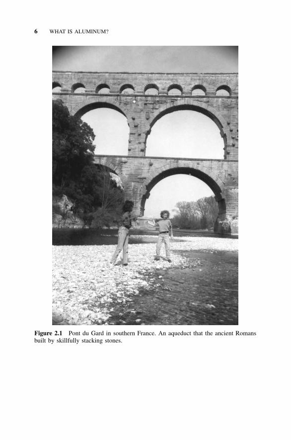
Prior to the development of commercially viable methods of producingiron, almost all construction consisted of gravity structures. From the pyra-mids of the pharoahs to the neoclassical architecture of Napoleonic Europe,builders stacked stones in such a way that the dead load of the stone pilemaintained a compressive state of force on each component of the structure(see Figure 2.1). The development of methods to mass-produce iron, in ad-dition to spawning the Industrial Revolution in the nineteenth century, resultedin iron becoming commercially available as a material of construction. Ar-chitecture was then freed from the limitations of the stone pile by structuralcomponents that could be utilized in tension as well as compression. Amer-ican architect Frank Lloyd Wright observed that with the availability of ironas a construction material, ‘‘the architect is no longer hampered by the stonebeam of the Greeks or the stone arch of the Romans.’’ Early applications ofthis new design freedom were the great iron and glass railway stations of theVictorian era. Builders have been pursuing improvements to the iron beamever since.
An inherent drawback to building with iron as compared to the old stonepile is the propensity of iron to deteriorate by oxidation. Much of the effortto improve the iron beam has focused on this problem. One response has
6 WHAT IS ALUMINUM?
Figure 2.1 Pont du Gard in southern France. An aqueduct that the ancient Romansbuilt by skillfully stacking stones.
2.2 MANY METALS FROM WHICH TO CHOOSE 7
been to cover iron structures with a protective coating. The term coating maybe taken as a reference to paint, but it is really much broader than that. Whatis reinforced concrete, for example, but steel with a very thick and brittlecoating? Because concrete is brittle, it tends to crack and expose the steelreinforcing bars to corrosion. One of the functions served by prestressing orposttensioning is to apply a compressive force to the concrete in order to keepthese cracks from opening.
While one approach has been to apply coatings to prevent metal fromrusting, another has been to develop metals that inherently don’t rust. Rustmay be roughly defined as that dull reddish-brown stuff that shiny steel be-comes as it oxidizes. Thus, the designation of ‘‘stainless’’ to those iron-basedmetals that have sufficient chromium content to prohibit rusting of the basemetal in atmospheric service. The ‘‘stain’’ that is presented is the rust stain.Stainless steel must have been a term that originated in someone’s marketingdepartment. The term confers a quality of having all the positive attributes ofsteel but none of the drawbacks.
If we were to apply a similar marketing strategy to aluminum, we mightcall it ‘‘light stainless steel.’’ After all, it prevents the rust stain as surely asstainless steel does, and it weighs only about one-third as much. Engineerswho regard aluminum as an alien material may be more favorably disposedtoward ‘‘light stainless steel.’’
For the past century and a half, then, structural engineers have relied onmetals to impart tension-carrying capability to structural components. Tech-nical development during that time has included improvement in the prop-erties of the metals available for construction. One of the tasks of designersis to determine which metal best suits a given application.
2.2 MANY METALS FROM WHICH TO CHOOSE
Structural metals are often referred to in the singular sense, such as ‘‘steel,’’‘‘stainless steel,’’ or ‘‘aluminum,’’ but, in fact, each of these labels applies toa family of metals. The label indicates the primary alloying element, andindividual alloys are then defined by the amounts of other elements contained,such as carbon, nickel, chromium, and manganese. The properties of an alloyare determined by the proportions of these alloying elements, just as thecharacteristics of a dessert are dependent on the relative amounts of eachingredient in the recipe. For example, when you mix pumpkin, spices, sugar,salt, eggs, and milk in the proper quantities, you make a pumpkin pie filling.By adding flour and adjusting the proportions, you can make pumpkin bread.Substituting shortening for the pumpkin and molasses for the milk yieldsginger cookies. Each adjustment of the recipe results in a different dessert.Whereas the addition of flour can turn pie filling into bread, adding enoughchromium to steel makes it stainless steel.
8 WHAT IS ALUMINUM?
While this is a somewhat facetious illustration, our point is that just as theterm dessert refers to a group of individual mixtures, so does the term steel.Steel designates a family of iron-based alloys. When the chromium contentof an iron-based alloy is above 10.5%, it is dubbed stainless steel (136). Evenwithin the stainless steel family, dozens of recognized alloys exist, each withdifferent combinations of alloying ingredients. Type 405 stainless steel, forexample, contains 11.5% to 14.5% chromium and 1.0% or less of severalother elements, including carbon, manganese, silicon, and aluminum. Shouldthe alchemist modify the mixture, such as by switching the relative amountsof iron and aluminum, substituting copper for carbon and magnesium formanganese, and then leaving out the chromium, the alloy might match thecomposition of aluminum alloy 2618. As this four-digit label implies, it isbut one of many aluminum alloys. Just as with desserts, there is no one bestmetal mixture, but rather different mixtures are appropriate for different oc-casions. The intent of this text is to add aluminum-based recipes to the rep-ertoire of structural engineers who already know how to cook with steel.
2.3 WHEN TO CHOOSE ALUMINUM
2.3.1 Introduction
Today aluminum suffers from a malady similar to that which afflicted toma-toes in the eighteenth century: many people fail to consider it out of super-stition and ignorance. Whereas Europeans shunned tomatoes for fear that theywere poisonous, engineers seem to avoid aluminum for equally unfoundedreasons today.
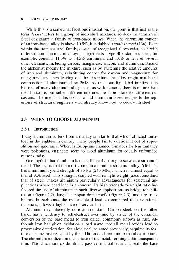
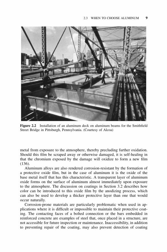
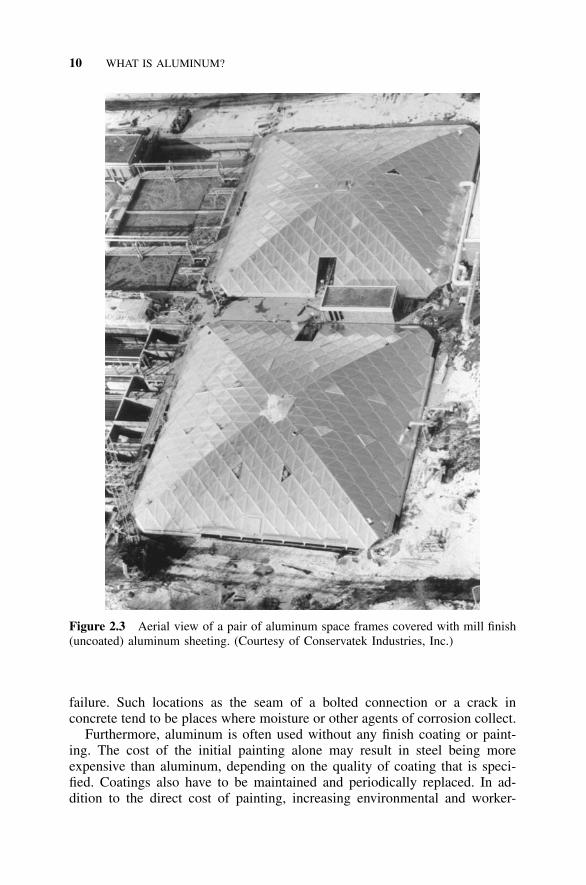
One myth is that aluminum is not sufficiently strong to serve as a structuralmetal. The fact is that the most common aluminum structural alloy, 6061-T6,has a minimum yield strength of 35 ksi [240 MPa], which is almost equal tothat of A36 steel. This strength, coupled with its light weight (about one-thirdthat of steel), makes aluminum particularly advantageous for structural ap-plications where dead load is a concern. Its high strength-to-weight ratio hasfavored the use of aluminum in such diverse applications as bridge rehabili-tation (Figure 2.2), large clear-span dome roofs (Figure 2.3), and fire truckbooms. In each case, the reduced dead load, as compared to conventionalmaterials, allows a higher live or service load.
Aluminum is inherently corrosion-resistant. Carbon steel, on the otherhand, has a tendency to self-destruct over time by virtue of the continualconversion of the base metal to iron oxide, commonly known as rust. Al-though iron has given oxidation a bad name, not all metal oxides lead toprogressive deterioration. Stainless steel, as noted previously, acquires its fea-ture of being rust-resistant by the addition of chromium to the alloy mixture.The chromium oxidizes on the surface of the metal, forming a thin transparentfilm. This chromium oxide film is passive and stable, and it seals the base
2.3 WHEN TO CHOOSE ALUMINUM 9
Figure 2.2 Installation of an aluminum deck on aluminum beams for the SmithfieldStreet Bridge in Pittsburgh, Pennsylvania. (Courtesy of Alcoa)
metal from exposure to the atmosphere, thereby precluding further oxidation.Should this film be scraped away or otherwise damaged, it is self-healing inthat the chromium exposed by the damage will oxidize to form a new film(136).
Aluminum alloys are also rendered corrosion-resistant by the formation ofa protective oxide film, but in the case of aluminum it is the oxide of thebase metal itself that has this characteristic. A transparent layer of aluminumoxide forms on the surface of aluminum almost immediately upon exposureto the atmosphere. The discussion on coatings in Section 3.2 describes howcolor can be introduced to this oxide film by the anodizing process, whichcan also be used to develop a thicker protective layer than one that wouldoccur naturally.
Corrosion-prone materials are particularly problematic when used in ap-plications where it is difficult or impossible to maintain their protective coat-ing. The contacting faces of a bolted connection or the bars embedded inreinforced concrete are examples of steel that, once placed in a structure, arenot accessible for future inspection or maintenance. Inaccessibility, in additionto preventing repair of the coating, may also prevent detection of coating
10 WHAT IS ALUMINUM?
Figure 2.3 Aerial view of a pair of aluminum space frames covered with mill finish(uncoated) aluminum sheeting. (Courtesy of Conservatek Industries, Inc.)
failure. Such locations as the seam of a bolted connection or a crack inconcrete tend to be places where moisture or other agents of corrosion collect.
Furthermore, aluminum is often used without any finish coating or paint-ing. The cost of the initial painting alone may result in steel being moreexpensive than aluminum, depending on the quality of coating that is speci-fied. Coatings also have to be maintained and periodically replaced. In ad-dition to the direct cost of painting, increasing environmental and worker-
2.3 WHEN TO CHOOSE ALUMINUM 11
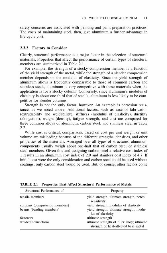
TABLE 2.1 Properties That Affect Structural Performance of Metals
Structural Performance of Property
tensile members yield strength, ultimate strength, notchsensitivity
columns (compression members) yield strength, modulus of elasticitybeams (bending members) yield strength, ultimate strength, modu-
lus of elasticityfasteners ultimate strengthwelded connections ultimate strength of filler alloy; ultimate
strength of heat-affected base metal
safety concerns are associated with painting and paint preparation practices.The costs of maintaining steel, then, give aluminum a further advantage inlife-cycle cost.
2.3.2 Factors to Consider
Clearly, structural performance is a major factor in the selection of structuralmaterials. Properties that affect the performance of certain types of structuralmembers are summarized in Table 2.1.
For example, the strength of a stocky compression member is a functionof the yield strength of the metal, while the strength of a slender compressionmember depends on the modulus of elasticity. Since the yield strength ofaluminum alloys is frequently comparable to those of common carbon andstainless steels, aluminum is very competitive with these materials when theapplication is for a stocky column. Conversely, since aluminum’s modulus ofelasticity is about one-third that of steel’s, aluminum is less likely to be com-petitive for slender columns.
Strength is not the only factor, however. An example is corrosion resis-tance, as we noted above. Additional factors, such as ease of fabrication(extrudability and weldability), stiffness (modulus of elasticity), ductility(elongation), weight (density), fatigue strength, and cost are compared forthree common alloys of aluminum, carbon steel, and stainless steel in Table2.2.
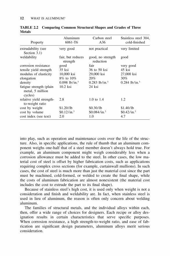
While cost is critical, comparisons based on cost per unit weight or unitvolume are misleading because of the different strengths, densities, and otherproperties of the materials. Averaged over all types of structures, aluminumcomponents usually weigh about one-half that of carbon steel or stainlesssteel members. Given this and assigning carbon steel a relative cost index of1 results in an aluminum cost index of 2.0 and stainless cost index of 4.7. Ifinitial cost were the only consideration and carbon steel could be used withoutcoatings, only carbon steel would be used. But, of course, other factors come
12 WHAT IS ALUMINUM?
TABLE 2.2 Comparing Common Structural Shapes and Grades of ThreeMetals
PropertyAluminum6061-T6
Carbon steelA36
Stainless steel 304,cold-finished
extrudability (seeSection 3.1)
very good not practical very limited
weldability fair, but reducesstrength
good, no strengthreduction
good
corrosion resistance good fair very goodtensile yield strength 35 ksi 36 to 50 ksi 45 ksimodulus of elasticity 10,000 ksi 29,000 ksi 27,000 ksielongation 8% to 10% 20% 30%density 0.098 lb/ in.3 0.283 lb/ in.3 0.284 lb/ in.3
fatigue strength (plainmetal, 5 millioncycles)
10.2 ksi 24 ksi
relative yield strength-to-weight ratio
2.8 1.0 to 1.4 1.2
cost by weight $1.20/ lb $0.30/ lb $1.40/ lbcost by volume $0.12/ in.3 $0.084/ in.3 $0.42/ in.3
cost index (see text) 2.0 1.0 4.7
into play, such as operation and maintenance costs over the life of the struc-ture. Also, in specific applications, the rule of thumb that an aluminum com-ponent weighs one-half that of a steel member doesn’t always hold true. Forexample, an aluminum component might weigh considerably less when acorrosion allowance must be added to the steel. In other cases, the low ma-terial cost of steel is offset by higher fabrication costs, such as applicationsrequiring complex cross sections (for example, curtainwall mullions). In suchcases, the cost of steel is much more than just the material cost since the partmust be machined, cold-formed, or welded to create the final shape, whilethe costs of aluminum fabrication are almost nonexistent (the material costincludes the cost to extrude the part to its final shape).
Because of stainless steel’s high cost, it is used only when weight is not aconsideration and finish and weldability are. In fact, when stainless steel isused in lieu of aluminum, the reason is often only concern about weldingaluminum.
The families of structural metals, and the individual alloys within each,then, offer a wide range of choices for designers. Each recipe or alloy des-ignation results in certain characteristics that serve specific purposes.When corrosion resistance, a high strength-to-weight ratio, and ease of fab-rication are significant design parameters, aluminum alloys merit seriousconsideration.
2.4 ALUMINUM ALLOYS AND TEMPERS 13
2.4 ALUMINUM ALLOYS AND TEMPERS
2.4.1 Introduction
While sometimes it is appropriate to bake flour mixed with nothing but water,such as when one is hurrying out of Egypt with a pharoah in hot pursuit,baked goods are generally improved by the judicious addition of other ingre-dients. Whether the base is bran flour or corn flour, transforming the flourinto muffins requires throwing in a pinch of this or that. So it is for alloys.Whether the base metal is iron or aluminum, it is rarely used in its pure form.Small amounts (often less than 1%) of other elements, which are sometimescalled hardeners, are required to attain more useful properties.
One of the properties of critical interest for structural metals is theirstrength. Unalloyed aluminum has an ultimate tensile strength of about 13kips/in.2 (ksi) [90 MPa]. This value can be increased by more than 30 ksi[200 MPa], however, by adding a dash of zinc, then throwing in a pinch ortwo of copper and magnesium and just a smidgen of chromium. Putting thisrecipe in the oven and heating it at the prescribed temperature and durationcan bring the strength up to more than 80 ksi [550 MPa]. Variations on theingredients and heating instructions can yield alloys to meet almost any en-gineering appetite.
Aluminum alloys are divided into two categories: wrought alloys, thosethat are worked to shape, and cast alloys, those that are poured in a moltenstate into a mold that determines their shape. The Aluminum Associationmaintains an internationally recognized designation system for each category,described in ANSI H35.1, Alloy and Temper Designation Systems for Alu-minum (42). The wrought alloy designation system is discussed in the nextsection and the cast alloy system in Section 3.1.4. While strength and otherproperties of both wrought and cast products are dependent on their ingre-dients, or the selective addition of alloying elements, further variations onthese properties can be achieved by tempering. Tempering refers to the alter-ation of the mechanical properties of a metal by means of either a mechanicalor thermal treatment. Temper can be produced in wrought products by thestrain-hardening that results from cold working. Thermal treatments may beused to obtain temper in cast products, as well as in those wrought alloysidentified as heat-treatable. Conversely, the wrought alloys that can only bestrengthened by cold work are designated non-heat-treatable.
2.4.2 Wrought Alloys
The Aluminum Association’s designation system for aluminum alloys wasintroduced in 1954. Under this system, a four-digit number is assigned toeach alloy registered with the Association. The first number of the alloy des-ignates the primary alloying element, which produces a group of alloys withsimilar properties. The Association sequentially assigns the last two digits.
14 WHAT IS ALUMINUM?
TABLE 2.3 Wrought Alloy Designation System and Characteristics
SeriesNumber
Primary AlloyingElement
RelativeCorrosionResistance
RelativeStrength Heat Treatment
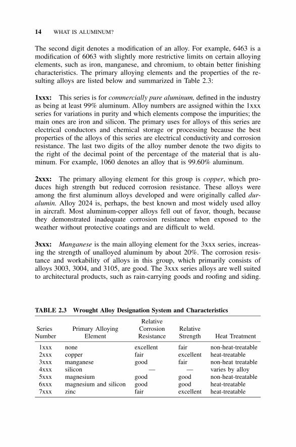
1xxx none excellent fair non-heat-treatable2xxx copper fair excellent heat-treatable3xxx manganese good fair non-heat treatable4xxx silicon — — varies by alloy5xxx magnesium good good non-heat-treatable6xxx magnesium and silicon good good heat-treatable7xxx zinc fair excellent heat-treatable
The second digit denotes a modification of an alloy. For example, 6463 is amodification of 6063 with slightly more restrictive limits on certain alloyingelements, such as iron, manganese, and chromium, to obtain better finishingcharacteristics. The primary alloying elements and the properties of the re-sulting alloys are listed below and summarized in Table 2.3:
1xxx: This series is for commercially pure aluminum, defined in the industryas being at least 99% aluminum. Alloy numbers are assigned within the 1xxxseries for variations in purity and which elements compose the impurities; themain ones are iron and silicon. The primary uses for alloys of this series areelectrical conductors and chemical storage or processing because the bestproperties of the alloys of this series are electrical conductivity and corrosionresistance. The last two digits of the alloy number denote the two digits tothe right of the decimal point of the percentage of the material that is alu-minum. For example, 1060 denotes an alloy that is 99.60% aluminum.
2xxx: The primary alloying element for this group is copper, which pro-duces high strength but reduced corrosion resistance. These alloys wereamong the first aluminum alloys developed and were originally called dur-alumin. Alloy 2024 is, perhaps, the best known and most widely used alloyin aircraft. Most aluminum-copper alloys fell out of favor, though, becausethey demonstrated inadequate corrosion resistance when exposed to theweather without protective coatings and are difficult to weld.
3xxx: Manganese is the main alloying element for the 3xxx series, increas-ing the strength of unalloyed aluminum by about 20%. The corrosion resis-tance and workability of alloys in this group, which primarily consists ofalloys 3003, 3004, and 3105, are good. The 3xxx series alloys are well suitedto architectural products, such as rain-carrying goods and roofing and siding.
2.4 ALUMINUM ALLOYS AND TEMPERS 15
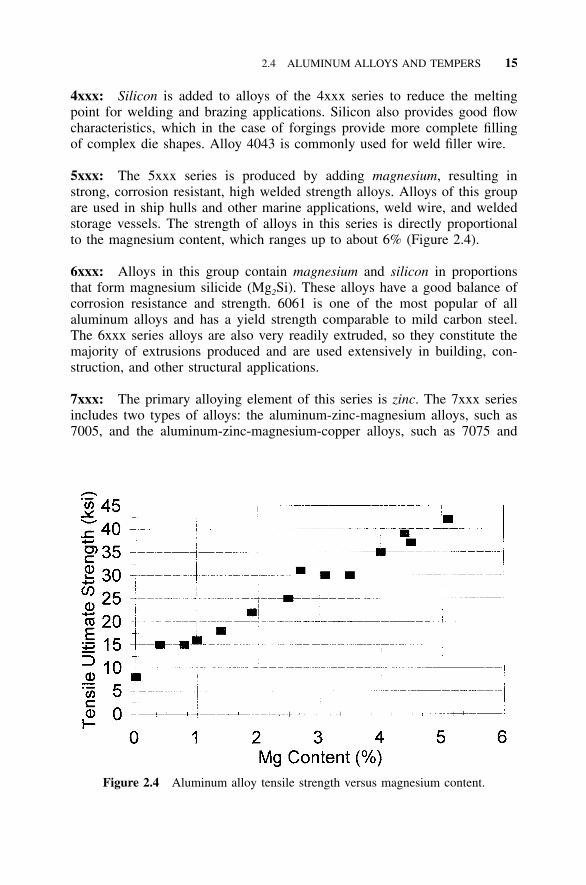
Figure 2.4 Aluminum alloy tensile strength versus magnesium content.
4xxx: Silicon is added to alloys of the 4xxx series to reduce the meltingpoint for welding and brazing applications. Silicon also provides good flowcharacteristics, which in the case of forgings provide more complete fillingof complex die shapes. Alloy 4043 is commonly used for weld filler wire.
5xxx: The 5xxx series is produced by adding magnesium, resulting instrong, corrosion resistant, high welded strength alloys. Alloys of this groupare used in ship hulls and other marine applications, weld wire, and weldedstorage vessels. The strength of alloys in this series is directly proportionalto the magnesium content, which ranges up to about 6% (Figure 2.4).
6xxx: Alloys in this group contain magnesium and silicon in proportionsthat form magnesium silicide (Mg2Si). These alloys have a good balance ofcorrosion resistance and strength. 6061 is one of the most popular of allaluminum alloys and has a yield strength comparable to mild carbon steel.The 6xxx series alloys are also very readily extruded, so they constitute themajority of extrusions produced and are used extensively in building, con-struction, and other structural applications.
7xxx: The primary alloying element of this series is zinc. The 7xxx seriesincludes two types of alloys: the aluminum-zinc-magnesium alloys, such as7005, and the aluminum-zinc-magnesium-copper alloys, such as 7075 and
16 WHAT IS ALUMINUM?
7178. The alloys of this group include the strongest aluminum alloy, 7178,which has a minimum tensile ultimate strength of 84 ksi [580 MPa] in theT6 temper, and are used in aircraft frames and structural components. Thecorrosion resistance of those 7xxx series alloys alloyed with copper is less,however, than the 1xxx, 3xxx, 5xxx, and 6xxx series, while the corrosionresistance of the 7xxx alloys alloyed without copper is fairly good. Some7xxx alloys without copper, such as 7008 and 7072, are used as cladding tocathodically protect less corrosion resistant alloys.
8xxx: The 8xxx series is reserved for alloying elements other than thoseused for series 2xxx through 7xxx. Iron and nickel are used to increasestrength without significant loss in electrical conductivity, and so are usefulin such conductor alloys as 8017. Aluminum-lithium alloy 8090, which hasexceptionally high strength and stiffness, was developed for aerospace appli-cations (see Section 9.3.3).
9xxx: This series is not currently used.
Experimental alloys are designated in accordance with the above system,but with the prefix ‘‘X’’ until they are no longer experimental. Producers mayalso offer proprietary alloys to which they assign their own designationnumbers.
This wrought alloy designation system had 357 registered alloys by 2001(19), but only 81 appear in the Aluminum Association’s Aluminum Standardsand Data 2000 (11) and 22 in the Association’s Specification for AluminumStructures (4), an indication that only a small percentage are commonly used.The signatories to the international accord on the designation system includeorganizations in the U.S., Russia, the United Kingdom, South Africa, Ger-many, Brazil, Belgium, Italy, Australia, Spain, China, Austria, France, Argen-tina, Mexico, Poland, Japan, Peru, Romania, Norway, Netherlands, and Swit-zerland, and the European Aluminum Association, so the system enjoysnearly global recognition. While the international accord has done much tostandardize designations, given the number of signatories, it is perhaps notsurprising the registration of so-called ‘‘national variations’’ has compromiseduniformity. (There were 55 of these at last count in 2001.) Such variationsare assigned a capital letter following the numerical designation (for example,6005A, is used in Europe and is a variation on 6005). The chemical com-position limits for national variations are similar to the Aluminum Associationlimits but vary slightly. Also, old habits die hard, and often the previousdesignations used in various European countries are used informally there.
Don’t be alarmed if you see yet other designations for aluminum alloysthat use the system described above but with a prefix. The Unified NumberingSystem (UNS), which the Society of Automotive Engineers and ASTM inconjunction with other technical societies, U.S. government agencies, and
2.4 ALUMINUM ALLOYS AND TEMPERS 17
trade associations developed to identify metals and alloys, includes aluminumalloys. The UNS number for wrought aluminum alloys uses the same numberas the Aluminum Association designation but precedes it with ‘‘A9’’ (forexample, UNS A95052 for 5052) in order to differentiate aluminum alloysfrom other metal alloys covered by the UNS. The UNS number for castaluminum alloys also uses the same number as the Aluminum Associationdesignation (discussed below) but precedes it with ‘‘A’’ and a number ‘‘0’’ orhigher (for example, UNS A14440 for A444.0).
You can also still come across the pre-1954 designations, usually whensomeone who doesn’t know much about aluminum quotes an old reference.To help in these instances, as well as when you’re confronted with modifyingan historic aluminum structure, a cross reference between the old systemdesignations and the new is given in Appendix A. What’s probably even moreamazing than the fact that these designations still occasionally appear is thatmany of the old alloys, such as 24S (now 2024), 43S (4043), and 61S (6061),are still popular. You’ll also still occasionally hear reference to duralumin,the commercial name given to the original aluminum-copper alloys. Unfor-tunately these alloys proved to be the least durable of aluminum, and use ofthe name has faded.
Informal appellations are also given to aluminum alloy series. The 2xxxand 7xxx series are sometimes referred to as ‘‘aircraft alloys,’’ but they arealso used in other applications, including bolts and screws used in buildings.The 1xxx, 3xxx, and 6xxx series alloys are sometimes referred to as ‘‘soft,’’while the 2xxx, 5xxx, and 7xxx series alloys are called ‘‘hard.’’ This descrip-tion refers to the ease of extruding the alloys: hard alloys are more difficultto extrude, requiring higher-capacity presses, and are, thus, more expensive.
2.4.3 Tempers
Aluminum alloys are tempered by heat treating or strain hardening to furtherincrease strength beyond the strengthening effect of adding alloying elements.Alloys are divided into two groups based on whether or not their strengthscan be increased by heat treating. Both heat treatable and non-heat treatablealloys can be strengthened by strain hardening, which is also called cold-working. The alloys that are not heat-treatable may only be strengthened bycold-working. Whether or not an alloy is heat treatable depends on its alloyingelements. Alloys in which the amount of alloying element in solid solutionin aluminum increases with temperature are heat treatable. In general, the1xxx, 3xxx, 4xxx, and 5xxx series wrought alloys are not heat treatable, whilethe 2xxx, 6xxx, and 7xxx wrought series are, but minor exceptions to thisrule exist.
Non-heat treatable alloys may also undergo a heat treatment, but this heattreatment is used only to stabilize properties so that strengths do not decreaseover time—behavior called age softening—and is required only for alloys
18 WHAT IS ALUMINUM?
with an appreciable amount of magnesium (the 5xxx series). Heating to 225�Fto 350�F [110�C to 180�C] causes all the softening to occur at once and, thus,is used as the stabilization heat treatment.
Before tempering, alloys begin in the annealed condition, the weakest butmost ductile condition. Tempering, while increasing the strength, decreasesductility and, therefore, decreases workability.
Strain hardening is achieved by mechanical deformation of the material atambient temperature. In the case of sheet and plate, this is done by reducingits thickness by rolling. As the material is worked, it becomes resistant tofurther deformation and its strength increases.
Two heat treatments can be applied to annealed condition, heat treatablealloys. First, the material can be solution heat treated. This allows solublealloying elements to enter into solid solution; they are retained in a super-saturated state upon quenching, a controlled rapid cooling usually performedusing air or water. Next, the material may undergo a precipitation heat treat-ment, which is also called artificial aging. Here, constituents are precipitatedfrom solid solution to increase the strength. An example of this process isthe production of 6061-T6 sheet. From its initial condition, 6061-O annealedmaterial is heat treated to 990�F [530�C] as rapidly as possible (solution heattreated), then cooled as rapidly as possible (quenched), which renders thetemper T4. The material is then heated to 320�F [160�C] and held for 18hours (precipitation heat treated); upon cooling to room temperature, the tem-per is T6.
Solution heat treated aluminum may also undergo natural aging. Naturalaging, like artificial aging, is a precipitation of alloying elements from solidsolution, but because it occurs at room temperature, it occurs much moreslowly (over a period of days and months rather than hours) than artificialaging. Both aging processes result in an increase in strength and a corre-sponding decrease in ductility. Material that will be subjected to severe form-ing operations, such as cold heading wire to make rivets or bolts, is oftenpurchased in a T4 temper, formed, and then artificially aged or allowed tonaturally age. Care must be taken to perform the forming operation beforetoo long a period of time elapses, or natural aging of the material will causeit to harden and decrease its workability. Sometimes T4 material is refriger-ated to prevent natural aging if cold forming required for fabrication into aproduct, such as a fastener or a tapered pole, will not be performed shortlyafter solution heat treatment.
The temper designation system is the same for both wrought and castalloys, although cast alloys are only heat treated and not strain hardened, withthe exception of some 85x.0 casting alloys. The temper designation followsthe alloy designation, the two being separated by a hyphen, for example,5052-H32. Basic temper designations are letters. Subdivisions of the basictempers are given by one or more numbers following the letter.
The basic temper designations are:
2.4 ALUMINUM ALLOYS AND TEMPERS 19
F As fabricated. Applies to the products of shaping processes in which nospecial control over thermal conditions or strain hardening is employed. Forwrought products, no mechanical property limits exist.
O Annealed. Applies to wrought products that are annealed to obtain thelowest strength temper, and to cast products that are annealed to improveductility and dimensional stability. The ‘‘O’’ may be followed by a numberother than zero.
H Strain-hardened (wrought products only). Applies to products that havetheir strength increased by strain-hardening, with or without supplementarythermal treatments, to produce some reduction in strength. The ‘‘H’’ is alwaysfollowed by two or more numbers.
W Solution heat-treated. An unstable temper applicable only to alloys thatspontaneously age at room temperature after solution heat-treatment. Thisdesignation is specific only when the period of natural aging is indicated, forexample, W hour.1–2
T Thermally treated to produce stable tempers other than F, O, or H.Applies to products that are thermally treated, with or without supplementarystrain-hardening, to produce stable tempers. The ‘‘T’’ is always followed byone or more numbers.
Strain-Hardened Tempers For strain-hardened tempers, the first digit of thenumber following the ‘‘H’’ denotes:
H1 Strain-hardened only. Applies to products that are strain-hardened toobtain the desired strength without supplementary thermal treatment. Thenumber following this designation indicates the degree of strain-hardening,for example, 1100-H14.
H2 Strain-hardened and partially annealed. Applies to products that arestrain-hardened more than the desired final amount and then reduced instrength to the desired level by partial annealing. For alloys that age-softenat room temperature, the H2 tempers have the same minimum ultimate tensilestrength as the corresponding H3 tempers. For other alloys, the H2 tempershave the same minimum ultimate tensile strength as the corresponding H1tempers and slightly higher elongation. The number following this designationindicates the strain-hardening remaining after the product has been partiallyannealed, for example, 3005-H25.
H3 Strain-hardened and stabilized. Applies to products that are strain-hardened and whose mechanical properties are stabilized either by a low-temperature thermal treatment or as a result of heat introduced during fabri-
20 WHAT IS ALUMINUM?
TABLE 2.4 HX1 through HX9 Temper Example
Temper
Ultimate Tensile Strength
ksi MPa Description
5052-O 25 170 annealed5052-H32 31 215 -hard1–45052-H34 34 235 -hard1–25052-H36 37 255 -hard3–45052-H38 39 270 full-hard5052-H39 41 285
cation. Stabilization usually improves ductility. This designation is applicableonly to those alloys that, unless stabilized, gradually age-soften at room tem-perature. The number following this designation indicates the degree of strain-hardening remaining after the stabilization has occurred, for example, 5005-H34.
H4 Strain-hardened and lacquered or painted. Applies to products thatare strain-hardened and subjected to some thermal operation during subse-quent painting or lacquering. The number following this designation indicatesthe degree of strain-hardening remaining after the product has been thermallytreated as part of the painting or lacquering curing. The corresponding H2Xor H3X mechanical property limits apply.
The digit following the designation H1, H2, H3, or H4 indicates the degreeof strain-hardening. Number 8 is for the tempers with the highest ultimatetensile strength normally produced and is sometimes called full-hard. Number4 is for tempers whose ultimate strength is approximately midway betweenthat of the O temper and the HX8 temper, and so is sometimes called half-hard. Number 2 is for tempers whose ultimate strength is approximately mid-way between that of the O temper and the HX4 temper, which is calledquarter hard. Number 6 is for tempers whose ultimate strength is approxi-mately midway between that of the HX4 temper and the HX8 temper calledthree-quarter hard. Numbers 1, 3, 5, and 7 similarly designate intermediatetempers between those defined above. Number 9 designates tempers whoseminimum ultimate tensile strength exceeds that of the HX8 tempers by 2 ksi[15 MPa] or more. An example of the effect of the second digit is shown inTable 2.4.
The third digit, when used, indicates a variation in the degree of temperor the mechanical properties of a two-digit temper. An example is pattern orembossed sheet made from the H12, H22, or H32 tempers; these are assignedH124, H224, or H324 tempers, respectively, since the additional strain hard-ening from embossing causes a slight change in the mechanical properties.
2.4 ALUMINUM ALLOYS AND TEMPERS 21
Heat-Treated Tempers For heat-treated tempers, the numbers 1 through 10following the ‘‘T’’ denote:
T1 Cooled from an elevated temperature shaping process and naturallyaged to a substantially stable condition. Applies to products that are notcold-worked after cooling from an elevated temperature shaping process, orin which the effect of cold work in flattening or straightening may not berecognized in mechanical property limits, for example, 6005-T1 extrusions.
T2 Cooled from an elevated temperature shaping process, cold-worked,and naturally aged to a substantially stable condition. Applies to prod-ucts that are cold-worked to improve strength after cooling from an elevatedtemperature shaping process, or in which the effect of cold work in flatteningor straightening is recognized in mechanical property limits.
T3 Solution heat-treated, cold-worked, and naturally aged to a substan-tially stable condition. Applies to products that are cold-worked to improvestrength after solution heat treatment, or in which the effect of cold work inflattening or straightening is recognized in mechanical property limits, forexample, 2024-T3 sheet.
T4 Solution heat-treated and naturally aged to a substantially stable con-dition. Applies to products that are not cold-worked after solution heat treat-ment, or in which the effect of cold work in flattening or straightening maynot be recognized in mechanical property limits, for example, 2014-T4 sheet.
T5 Cooled from an elevated temperature shaping process and then arti-ficially aged. Applies to products that are not cold-worked after coolingfrom an elevated temperature shaping process, or in which the effect of coldwork in flattening or straightening may not be recognized in mechanical prop-erty limits, for example, 6063-T5 extrusions.
T6 Solution heat-treated and then artificially aged. Applies to productsthat are not cold-worked after solution heat treatment, or in which the effectof cold work in flattening or straightening may not be recognized in mechan-ical property limits, for example, 6063-T6 extrusions.
T7 Solution heat-treated and then overaged/stabilized. Applies towrought products that are artificially aged after solution heat treatment tocarry them beyond a point of maximum strength to provide control of somesignificant characteristic, for example, 7050-T7 rivet and cold heading wireand rod. Applies to cast products that are artificially aged after solution heattreatment to provide dimensional and strength stability.
22 WHAT IS ALUMINUM?
T8 Solution heat-treated, cold-worked, and then artificially aged.Applies to products that are cold-worked to improve strength, or in which theeffect of cold work in flattening or straightening is recognized in mechanicalproperty limits, for example, 2024-T81 sheet.
T9 Solution heat-treated, artificially aged, and then cold-worked.Applies to products that are cold-worked to improve strength after artificialaging, for example, 6262-T9 nuts.
T10 Cooled from an elevated temperature shaping process, cold-worked,and then artificially aged. Applies to products that are cold-worked toimprove strength, or in which the effect of cold work in flattening or straight-ening is recognized in mechanical property limits.
Additional digits may be added to designations T1 through T10 for vari-ations in treatment. Stress-relieved tempers follow various conventions, whichare described below.
Stress relieved by stretching:
T 51 Applies to plate and rolled or cold-finished rod or bar, die or ringforgings, and rolled rings when stretched after solution heat treatment or aftercooling from an elevated temperature shaping process. The products receiveno further straightening after stretching, for example, 6061-T651.
T 510 Applies to extruded rod, bar, profiles, and tubes, and to drawn tubewhen stretched after solution heat treatment or after cooling from an elevatedtemperature shaping process.
T 511 Applies to extruded rod, bar, profiles, and tubes, and to drawn tubewhen stretched after solution heat treatment or after cooling from an elevatedtemperature shaping process. These products may receive minor straighteningafter stretching to comply with standard tolerances.
These stress-relieved temper products usually have larger tolerances ondimensions than other products of other tempers.
Stress relieved by compressing:
T 52 Applies to products that are stress relieved by compressing aftersolution heat treatment or cooling from an elevated temperature shaping pro-cess to produce a permanent set of 1% to 5%.
Stress relieved by combined stretching and compressing:
T 54 Applies to die forgings that are stress relieved by restriking cold inthe finish die.
For wrought products heat-treated from annealed or F temper (or othertemper when such heat treatments result in the mechanical properties assignedto these tempers):
2.5 STRUCTURAL APPLICATIONS OF ALUMINUM 23
T42 Solution heat-treated from annealed or F temper and naturally aged toa substantially stable condition by the user (as opposed to the producer), forexample, 2024-T42.
T62 Solution heat-treated from annealed or F temper and artificially agedby the user (as opposed to the producer), for example, 6066-T62.
While the temper designations for wrought alloys are grouped accordingto whether the strength level was obtained by strain-hardening or by thermaltreatment, artificial aging is the more important distinction for structural de-sign purposes because it affects the shape of the stress-strain curve. The Alu-minum Specification gives one set of buckling constant formulas for the ar-tificially aged tempers (T5 through T10), and another set of formulas thatapplies to both the non-heat-treated alloys (H), as well as to the heat-treatedalloys that have not been artificially aged (T1 through T4). These bucklingconstants are discussed in detail in Section 5.2.1.
You’ll occasionally encounter tempers that don’t match any of the onesdescribed above, such as 6063-T53. Individual producers register these withthe Aluminum Association, which publishes their properties in Tempers forAluminum and Aluminum Alloy Products (25).
2.5 STRUCTURAL APPLICATIONS OF ALUMINUM
2.5.1 Background
Aluminum’s markets have developed gradually over the 100-year history ofcommercial production of the metal. Its first use was cooking utensils in the1890s, followed by electrical cable shortly after 1900, military uses in the1910s, and aircraft in the 1930s. Aluminum’s use in construction beganaround 1930, when landmark structures, such as the national Botanic GardenConservatory in Washington, DC, and the Chrysler and Empire State Build-ings in New York City were erected with aluminum structural components.Aluminum didn’t really crack the construction market until after World WarII, when aluminum was first used to clad buildings. This was done with theadvent of extrusions and curtainwall technology, discussed further below. The1960s saw the rapid expansion of aluminum’s largest market, packaging. Inthe 1990s, aluminum use in transportation has grown markedly, especially inautomobiles and light trucks.
Aluminum’s most recent markets are its largest—transportation, packaging,and construction, in that order—and together they account for two-thirds ofU.S. aluminum consumption (Table 2.5).
Applications of aluminum can be divided into two classes: structural andnonstructural. Structural applications are those for which the size of the partis driven primarily by the load which it must support; nonstructural applica-tions are the rest. About half the transportation and building and construction
24 WHAT IS ALUMINUM?
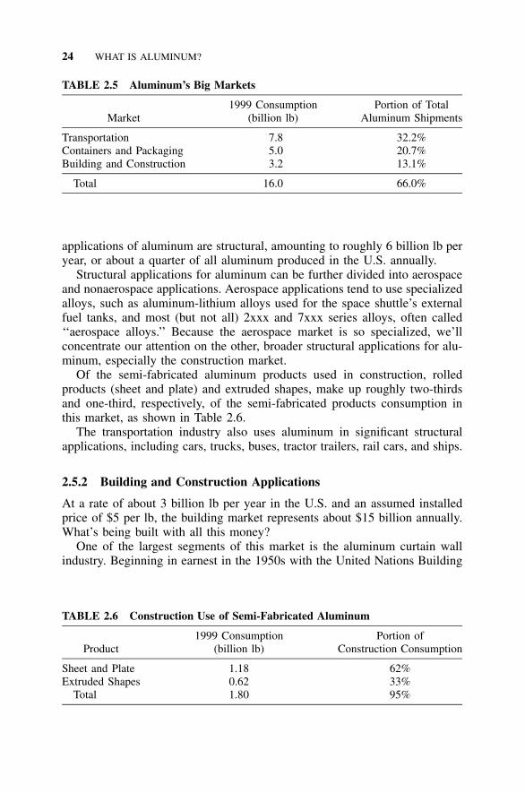
TABLE 2.5 Aluminum’s Big Markets
Market1999 Consumption
(billion lb)Portion of Total
Aluminum Shipments
Transportation 7.8 32.2%Containers and Packaging 5.0 20.7%Building and Construction 3.2 13.1%
Total 16.0 66.0%
TABLE 2.6 Construction Use of Semi-Fabricated Aluminum
Product1999 Consumption
(billion lb)Portion of
Construction Consumption
Sheet and Plate 1.18 62%Extruded Shapes 0.62 33%
Total 1.80 95%
applications of aluminum are structural, amounting to roughly 6 billion lb peryear, or about a quarter of all aluminum produced in the U.S. annually.
Structural applications for aluminum can be further divided into aerospaceand nonaerospace applications. Aerospace applications tend to use specializedalloys, such as aluminum-lithium alloys used for the space shuttle’s externalfuel tanks, and most (but not all) 2xxx and 7xxx series alloys, often called‘‘aerospace alloys.’’ Because the aerospace market is so specialized, we’llconcentrate our attention on the other, broader structural applications for alu-minum, especially the construction market.
Of the semi-fabricated aluminum products used in construction, rolledproducts (sheet and plate) and extruded shapes, make up roughly two-thirdsand one-third, respectively, of the semi-fabricated products consumption inthis market, as shown in Table 2.6.
The transportation industry also uses aluminum in significant structuralapplications, including cars, trucks, buses, tractor trailers, rail cars, and ships.
2.5.2 Building and Construction Applications
At a rate of about 3 billion lb per year in the U.S. and an assumed installedprice of $5 per lb, the building market represents about $15 billion annually.What’s being built with all this money?
One of the largest segments of this market is the aluminum curtain wallindustry. Beginning in earnest in the 1950s with the United Nations Building
2.5 STRUCTURAL APPLICATIONS OF ALUMINUM 25
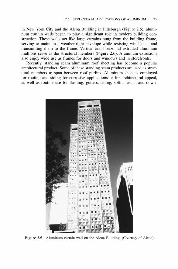
Figure 2.5 Aluminum curtain wall on the Alcoa Building. (Courtesy of Alcoa)
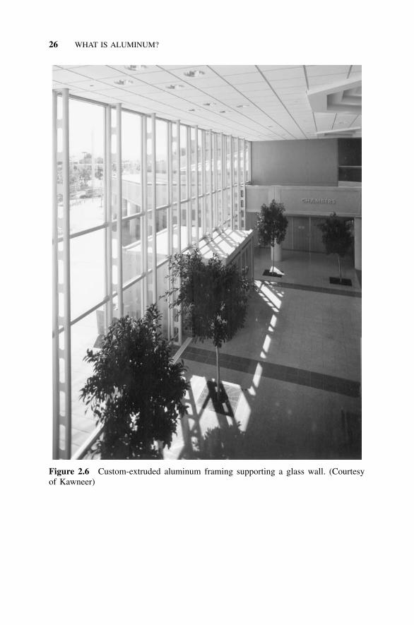
in New York City and the Alcoa Building in Pittsburgh (Figure 2.5), alumi-num curtain walls began to play a significant role in modern building con-struction. These walls act like large curtains hung from the building frame,serving to maintain a weather-tight envelope while resisting wind loads andtransmitting them to the frame. Vertical and horizontal extruded aluminummullions serve as the structural members (Figure 2.6). Aluminum extrusionsalso enjoy wide use as frames for doors and windows and in storefronts.
Recently, standing seam aluminum roof sheeting has become a populararchitectural product. Some of these standing seam products are used as struc-tural members to span between roof purlins. Aluminum sheet is employedfor roofing and siding for corrosive applications or for architectural appeal,as well as routine use for flashing, gutters, siding, soffit, fascia, and down-
26 WHAT IS ALUMINUM?
Figure 2.6 Custom-extruded aluminum framing supporting a glass wall. (Courtesyof Kawneer)
2.5 STRUCTURAL APPLICATIONS OF ALUMINUM 27
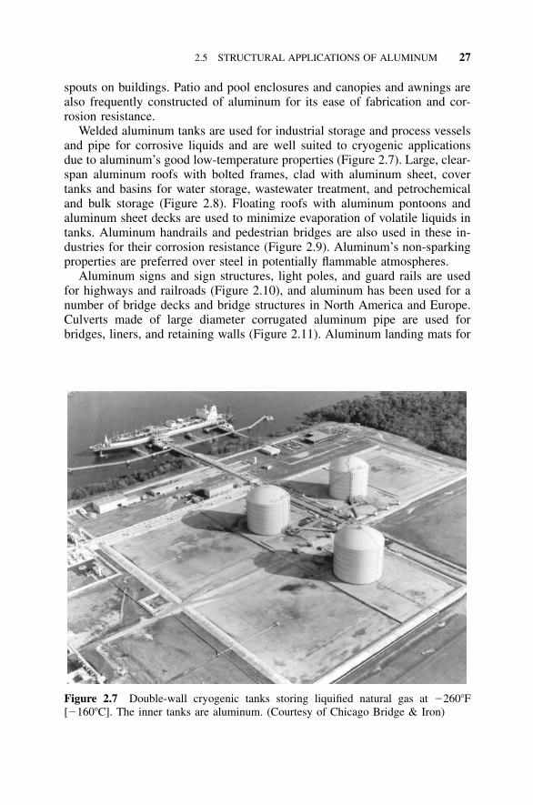
Figure 2.7 Double-wall cryogenic tanks storing liquified natural gas at �260�F[�160�C]. The inner tanks are aluminum. (Courtesy of Chicago Bridge & Iron)
spouts on buildings. Patio and pool enclosures and canopies and awnings arealso frequently constructed of aluminum for its ease of fabrication and cor-rosion resistance.
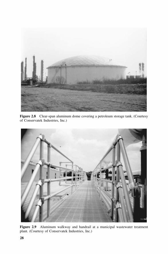
Welded aluminum tanks are used for industrial storage and process vesselsand pipe for corrosive liquids and are well suited to cryogenic applicationsdue to aluminum’s good low-temperature properties (Figure 2.7). Large, clear-span aluminum roofs with bolted frames, clad with aluminum sheet, covertanks and basins for water storage, wastewater treatment, and petrochemicaland bulk storage (Figure 2.8). Floating roofs with aluminum pontoons andaluminum sheet decks are used to minimize evaporation of volatile liquids intanks. Aluminum handrails and pedestrian bridges are also used in these in-dustries for their corrosion resistance (Figure 2.9). Aluminum’s non-sparkingproperties are preferred over steel in potentially flammable atmospheres.
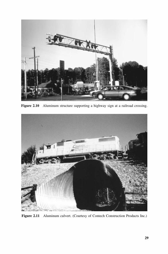
Aluminum signs and sign structures, light poles, and guard rails are usedfor highways and railroads (Figure 2.10), and aluminum has been used for anumber of bridge decks and bridge structures in North America and Europe.Culverts made of large diameter corrugated aluminum pipe are used forbridges, liners, and retaining walls (Figure 2.11). Aluminum landing mats for
28
Figure 2.8 Clear-span aluminum dome covering a petroleum storage tank. (Courtesyof Conservatek Industries, Inc.)
Figure 2.9 Aluminum walkway and handrail at a municipal wastewater treatmentplant. (Courtesy of Conservatek Industries, Inc.)
29
Figure 2.10 Aluminum structure supporting a highway sign at a railroad crossing.
Figure 2.11 Aluminum culvert. (Courtesy of Contech Construction Products Inc.)
30 WHAT IS ALUMINUM?
aircraft are tough and portable. Aluminum is also used for portable bridgesfor military vehicles.
Aluminum’s corrosion resistance lends itself to marine applications, in-cluding gangways and floating docks. To minimize the weight above the wa-terline to enhance stability, aluminum is often used in structures and decksfor offshore oil platforms.
A striking example of aluminum’s use as construction equipment is the 37miles of aluminum pipe used as scaffolding for the renovation of the Wash-ington Monument in 1999. (This seemed only fitting, since a 9 inch tall-aluminum pyramid had been used to cap the structure, then the tallest in theworld, upon its completion in 1884.) Aluminum is also used for ladders,trench shoring, and concrete forms because of its strength, durability, andlight weight.
31
3 Working with Aluminum
Now that you’ve heard about aluminum, you may want to know what it lookslike. We’ll describe it, beginning with the forms in which it is produced, howthese forms are shaped and altered to become structural components, and howthese components can be dressed up with coatings. We will include somecomments on how this process differs from the preparation of steel for dutyand will conclude with a few suggestions on how to put the structural com-ponents into place. This chapter, then, presents the product forms in whichaluminum is most commonly used for structural components, and how theseproduct forms are fabricated and erected.
3.1 PRODUCT FORMS
The forms of aluminum used in structural components include extrusions,flat-rolled products, castings, and forgings. The most widely used of theseforms are extrusions and the flat-rolled products, sheet and plate. Castingstypically have less reliable properties than the wrought product forms, andforgings are often more expensive to produce than other wrought forms. Cast-ings and forgings do, however, lend themselves to more complex shapes thanextrusions and flat-rolled products.
3.1.1 Extrusions
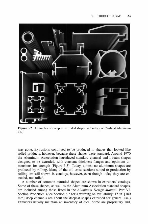
Introduction What do aluminum and Play-Doh have in common? They canboth be extruded, of course (Figure 3.1). Extrusions are produced by pushingsolid material through an opening called a die to form parts with complexcross sections. Aluminum is not the only metal fabricated this way, but it isthe most readily and commonly extruded. (Stainless steel can also be ex-truded, but it requires such great pressures that only small and simple stainlessshapes can be made). The extrusion process makes aluminum an extremelyversatile material for structural design. Rather than being limited to the stan-dard rolled shapes, designers can concoct their own cross sections, puttingmaterial where it is needed. Solid and hollow cross sections, even sectionswith multiple hollows, can be readily extruded (Figure 3.2).
While extrusions dominate applications for parts with a constant cross sec-tion, bar and rod are also produced by rolling, and tubes and wire by drawing,
32 WORKING WITH ALUMINUM
Figure 3.1 Engineer of the future extruding a Play-Doh I-beam. (Play-Doh is aregistered trademark of Kenner.)
a process by which material is pulled (as opposed to pushed) through a dieto change the cross section or harden the material. Cold-finishing may beused to improve surface finish and dimensional tolerances. Sometimes a com-bination of methods is used; for example, tube may be extruded and thendrawn; bar may be rolled and then cold-finished. Products that have beencold-finished or drawn are held to tighter tolerances on cross-sectional di-mensions than extruded products.
Standard Extruded Shapes Before World War II, most aluminum shapeswere produced by rolling, like steel, and so had cross sections similar to thoseof steel. Many of these shapes had sloped flanges that facilitated rolling butcomplicated connection details. Wartime and postwar demand for aluminumproducts prompted better production techniques, especially extrusions, whicheventually displaced much of the rolled production. Since extrusions are notsubject to the limitations of the rolling process, the need for sloped flanges
3.1 PRODUCT FORMS 33
Figure 3.2 Examples of complex extruded shapes. (Courtesy of Cardinal AluminumCo.)
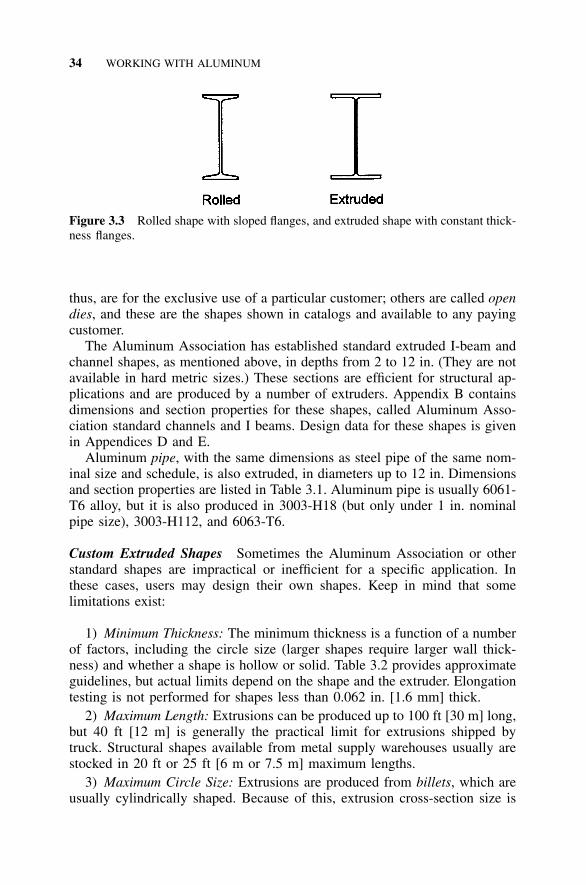
was gone. Extrusions continued to be produced in shapes that looked likerolled products, however, because these shapes were standard. Around 1970the Aluminum Association introduced standard channel and I-beam shapesdesigned to be extruded, with constant thickness flanges and optimum di-mensions for strength (Figure 3.3). Today, almost no aluminum shapes areproduced by rolling. Many of the old cross sections suited to production byrolling are still shown in catalogs, however, even though today they are ex-truded, not rolled.
A number of common extruded shapes are shown in extruders’ catalogs.Some of these shapes, as well as the Aluminum Association standard shapes,are included among those listed in the Aluminum Design Manual, Part VI,Section Properties. (See Section 6.2 for a warning on availability; 15 in. [380mm] deep channels are about the deepest shapes extruded for general use.)Extruders usually maintain an inventory of dies. Some are proprietary and,
34 WORKING WITH ALUMINUM
Figure 3.3 Rolled shape with sloped flanges, and extruded shape with constant thick-ness flanges.
thus, are for the exclusive use of a particular customer; others are called opendies, and these are the shapes shown in catalogs and available to any payingcustomer.
The Aluminum Association has established standard extruded I-beam andchannel shapes, as mentioned above, in depths from 2 to 12 in. (They are notavailable in hard metric sizes.) These sections are efficient for structural ap-plications and are produced by a number of extruders. Appendix B containsdimensions and section properties for these shapes, called Aluminum Asso-ciation standard channels and I beams. Design data for these shapes is givenin Appendices D and E.
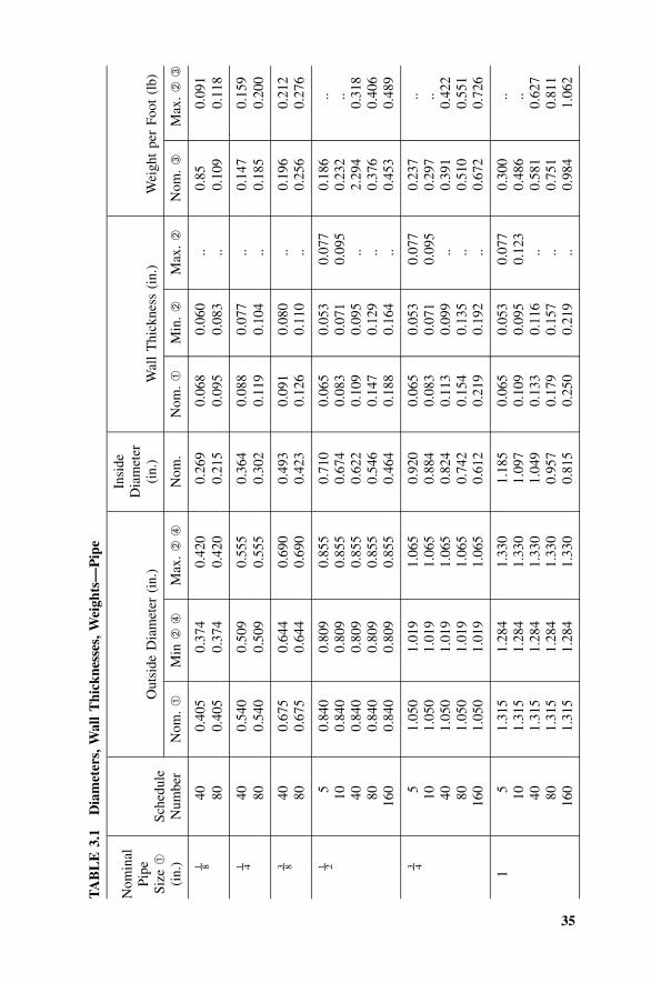
Aluminum pipe, with the same dimensions as steel pipe of the same nom-inal size and schedule, is also extruded, in diameters up to 12 in. Dimensionsand section properties are listed in Table 3.1. Aluminum pipe is usually 6061-T6 alloy, but it is also produced in 3003-H18 (but only under 1 in. nominalpipe size), 3003-H112, and 6063-T6.
Custom Extruded Shapes Sometimes the Aluminum Association or otherstandard shapes are impractical or inefficient for a specific application. Inthese cases, users may design their own shapes. Keep in mind that somelimitations exist:
1) Minimum Thickness: The minimum thickness is a function of a numberof factors, including the circle size (larger shapes require larger wall thick-ness) and whether a shape is hollow or solid. Table 3.2 provides approximateguidelines, but actual limits depend on the shape and the extruder. Elongationtesting is not performed for shapes less than 0.062 in. [1.6 mm] thick.
2) Maximum Length: Extrusions can be produced up to 100 ft [30 m] long,but 40 ft [12 m] is generally the practical limit for extrusions shipped bytruck. Structural shapes available from metal supply warehouses usually arestocked in 20 ft or 25 ft [6 m or 7.5 m] maximum lengths.
3) Maximum Circle Size: Extrusions are produced from billets, which areusually cylindrically shaped. Because of this, extrusion cross-section size is
35
TA
BL
E3.
1D
iam
eter
s,W
all
Thi
ckne
sses
,Wei
ghts
—P
ipe
Nom
inal
Pipe
Size
➀
(in.
)Sc
hedu
leN
umbe
r
Out
side
Dia
met
er(i
n.)
Nom
.➀
Min
➁➃
Max
.➁
➃
Insi
deD
iam
eter
(in.
)
Nom
.
Wal
lT
hick
ness
(in.
)
Nom
.➀
Min
.➁
Max
.➁
Wei
ght
per
Foot
(lb)
Nom
.➂
Max
.➁
➂
1 – 840
0.40
50.
374
0.42
00.
269
0.06
80.
060
..0.
850.
091
800.
405
0.37
40.
420
0.21
50.
095
0.08
3..
0.10
90.
118
1 – 440
0.54
00.
509
0.55
50.
364
0.08
80.
077
..0.
147
0.15
980
0.54
00.
509
0.55
50.
302
0.11
90.
104
..0.
185
0.20
0
3 – 840 80
0.67
50.
675
0.64
40.
644
0.69
00.
690
0.49
30.
423
0.09
10.
126
0.08
00.
110
.. ..0.
196
0.25
60.
212
0.27
6
1 – 25 10 40 80 160
0.84
00.
840
0.84
00.
840
0.84
0
0.80
90.
809
0.80
90.
809
0.80
9
0.85
50.
855
0.85
50.
855
0.85
5
0.71
00.
674
0.62
20.
546
0.46
4
0.06
50.
083
0.10
90.
147
0.18
8
0.05
30.
071
0.09
50.
129
0.16
4
0.07
70.
095
.. .. ..
0.18
60.
232
2.29
40.
376
0.45
3
.. ..0.
318
0.40
60.
489
3 – 45 10 40 80 160
1.05
01.
050
1.05
01.
050
1.05
0
1.01
91.
019
1.01
91.
019
1.01
9
1.06
51.
065
1.06
51.
065
1.06
5
0.92
00.
884
0.82
40.
742
0.61
2
0.06
50.
083
0.11
30.
154
0.21
9
0.05
30.
071
0.09
90.
135
0.19
2
0.07
70.
095
.. .. ..
0.23
70.
297
0.39
10.
510
0.67
2
.. ..0.
422
0.55
10.
726
15 10 40 80 160
1.31
51.
315
1.31
51.
315
1.31
5
1.28
41.
284
1.28
41.
284
1.28
4
1.33
01.
330
1.33
01.
330
1.33
0
1.18
51.
097
1.04
90.
957
0.81
5
0.06
50.
109
0.13
30.
179
0.25
0
0.05
30.
095
0.11
60.
157
0.21
9
0.07
70.
123
.. .. ..
0.30
00.
486
0.58
10.
751
0.98
4
.. ..0.
627
0.81
11.
062

36
TA
BL
E3.
1D
iam
eter
s,W
all
Thi
ckne
sses
,Wei
ghts
—P
ipe
(con
tinue
d)
Nom
inal
Pipe
Size
➀
(in.
)Sc
hedu
leN
umbe
r
Out
side
Dia
met
er(i
n.)
Nom
.➀
Min
➁➃
Max
.➁
➃
Insi
deD
iam
eter
(in.
)
Nom
.
Wal
lT
hick
ness
(in.
)
Nom
.➀
Min
.➁
Max
.➁
Wei
ght
per
Foot
(lb)
Nom
.➂
Max
.➁
➂
11 – 4
5 10 40 80 160
1.66
01.
660
1.66
01.
660
1.66
0
1.62
91.
629
1.62
91.
629
1.62
9
1.67
51.
675
1.67
51.
675
1.67
5
1.53
01.
442
1.38
01.
278
1.16
0
0.06
50.
109
0.14
00.
191
0.25
0
0.05
30.
095
0.12
20.
167
0.21
9
0.07
70.
123
.. .. ..
0.38
30.
625
0.78
61.
037
1.30
2
.. ..0.
849
1.12
01.
407
11 – 2
5 10 40 80 160
1.90
01.
900
1.90
01.
900
1.90
0
1.86
91.
869
1.86
91.
869
1.86
9
1.91
51.
915
1.91
51.
915
1.91
5
1.77
01.
682
1.61
01.
500
1.33
8
0.06
50.
109
0.14
50.
200
0.28
1
0.05
30.
095
0.12
70.
175
0.24
6
0.07
70.
123
.. .. ..
0.44
10.
721
0.94
01.
256
1.68
1
.. ..1.
015
1.35
71.
815
25 10 40 80 160
2.37
52.
375
2.37
52.
375
2.37
5
2.34
42.
344
2.35
12.
351
2.35
1
2.40
62.
406
2.39
92.
399
2.39
9
2.24
52.
157
2.06
71.
939
1.68
7
0.06
50.
109
0.15
40.
218
0.34
4
0.05
30.
095
0.13
50.
191
0.30
1
0.07
70.
123
.. .. ..
0.55
50.
913
1.26
41.
737
2.58
1
.. ..1.
365
1.87
62.
788
21 – 2
5 10 40 80 160
2.87
52.
875
2.87
52.
875
2.87
5
2.84
42.
844
2.84
62.
846
2.84
6
2.90
62.
906
2.90
42.
904
2.90
4
2.70
92.
635
2.46
92.
323
2.12
5
0.08
30.
120
0.20
30.
276
0.37
5
0.07
10.
105
0.17
80.
242
0.32
8
0.09
50.
135
.. .. ..
0.85
61.
221
2.00
42.
650
3.46
4
.. ..2.
164
2.86
23.
741
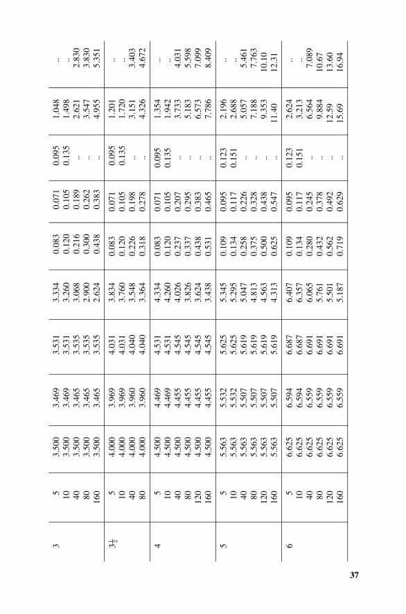
37
35 10 40 80 160
3.50
03.
500
3.50
03.
500
3.50
0
3.46
93.
469
3.46
53.
465
3.46
5
3.53
13.
531
3.53
53.
535
3.53
5
3.33
43.
260
3.06
82.
900
2.62
4
0.08
30.
120
0.21
60.
300
0.43
8
0.07
10.
105
0.18
90.
262
0.38
3
0.09
50.
135
.. .. ..
1.04
81.
498
2.62
13.
547
4.95
5
.. ..2.
830
3.83
05.
351
31 – 2
5 10 40 80
4.00
04.
000
4.00
04.
000
3.96
93.
969
3.96
03.
960
4.03
14.
031
4.04
04.
040
3.83
43.
760
3.54
83.
364
0.08
30.
120
0.22
60.
318
0.07
10.
105
0.19
80.
278
0.09
50.
135
.. ..
1.20
11.
720
3.15
14.
326
.. ..3.
403
4.67
2
45 10 40 80 120
160
4.50
04.
500
4.50
04.
500
4.50
04.
500
4.46
94.
469
4.45
54.
455
4.45
54.
455
4.53
14.
531
4.54
54.
545
4.54
54.
545
4.33
44.
260
4.02
63.
826
3.62
43.
438
0.08
30.
120
0.23
70.
337
0.43
80.
531
0.07
10.
105
0.20
70.
295
0.38
30.
465
0.09
50.
135
.. .. .. ..
1.35
41.
942
3.73
35.
183
6.57
37.
786
.. ..4.
031
5.59
87.
099
8.40
9
55 10 40 80 120
160
5.56
35.
563
5.56
35.
563
5.56
35.
563
5.53
25.
532
5.50
75.
507
5.50
75.
507
5.62
55.
625
5.61
95.
619
5.61
95.
619
5.34
55.
295
5.04
74.
813
4.56
34.
313
0.10
90.
134
0.25
80.
375
0.50
00.
625
0.09
50.
117
0.22
60.
328
0.43
80.
547
0.12
30.
151
.. .. .. ..
2.19
62.
688
5.05
77.
188
9.35
311
.40
.. ..5.
461
7.76
310
.10
12.3
1
65 10 40 80 120
160
6.62
56.
625
6.62
56.
625
6.62
56.
625
6.59
46.
594
6.55
96.
559
6.55
96.
559
6.68
76.
687
6.69
16.
691
6.69
16.
691
6.40
76.
357
6.06
55.
761
5.50
15.
187
0.10
90.
134
0.28
00.
432
0.56
20.
719
0.09
50.
117
0.24
50.
378
0.49
20.
629
0.12
30.
151
.. .. .. ..
2.62
43.
213
6.56
49.
884
12.5
915
.69
.. ..7.
089
10.6
713
.60
16.9
4
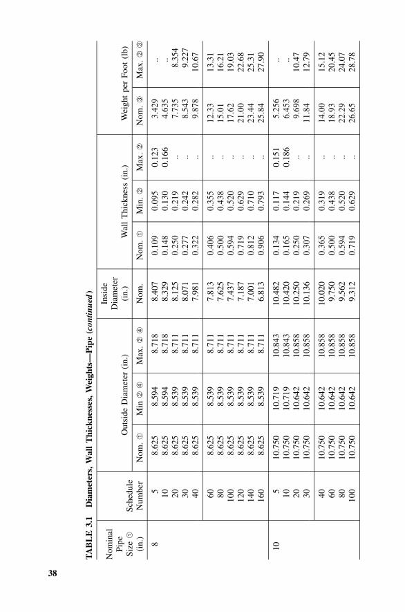
38
TA
BL
E3.
1D
iam
eter
s,W
all
Thi
ckne
sses
,Wei
ghts
—P
ipe
(con
tinue
d)
Nom
inal
Pipe
Size
➀
(in.
)Sc
hedu
leN
umbe
r
Out
side
Dia
met
er(i
n.)
Nom
.➀
Min
➁➃
Max
.➁
➃
Insi
deD
iam
eter
(in.
)
Nom
.
Wal
lT
hick
ness
(in.
)
Nom
.➀
Min
.➁
Max
.➁
Wei
ght
per
Foot
(lb)
Nom
.➂
Max
.➁
➂
85 10 20 30 40
8.62
58.
625
8.62
58.
625
8.62
5
8.59
48.
594
8.53
98.
539
8.53
9
8.71
88.
718
8.71
18.
711
8.71
1
8.40
78.
329
8.12
58.
071
7.98
1
0.10
90.
148
0.25
00.
277
0.32
2
0.09
50.
130
0.21
90.
242
0.28
2
0.12
30.
166
.. .. ..
3.42
94.
635
7.73
58.
543
9.87
8
.. ..8.
354
9.22
710
.67
60 80 100
120
140
160
8.62
58.
625
8.62
58.
625
8.62
58.
625
8.53
98.
539
8.53
98.
539
8.53
98.
539
8.71
18.
711
8.71
18.
711
8.71
18.
711
7.81
37.
625
7.43
77.
187
7.00
16.
813
0.40
60.
500
0.59
40.
719
0.81
20.
906
0.35
50.
438
0.52
00.
629
0.71
00.
793
.. .. .. .. .. ..
12.3
315
.01
17.6
221
.00
23.4
425
.84
13.3
116
.21
19.0
322
.68
25.3
127
.90
105 10 20 30
10.7
5010
.750
10.7
5010
.750
10.7
1910
.719
10.6
4210
.642
10.8
4310
.843
10.8
5810
.858
10.4
8210
.420
10.2
5010
.136
0.13
40.
165
0.25
00.
307
0.11
70.
144
0.21
90.
269
0.15
10.
186
.. ..
5.25
66.
453
9.69
811
.84
.. ..10
.47
12.7
9
40 60 80 100
10.7
5010
.750
10.7
5010
.750
10.6
4210
.642
10.6
4210
.642
10.8
5810
.858
10.8
5810
.858
10.0
209.
750
9.56
29.
312
0.36
50.
500
0.59
40.
719
0.31
90.
438
0.52
00.
629
.. .. .. ..
14.0
018
.93
22.2
926
.65
15.1
220
.45
24.0
728
.78
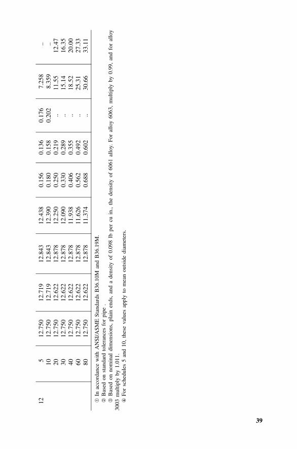
39
125 10 20 30 40 60 80
12.7
5012
.750
12.7
5012
.750
12.7
5012
.750
12.7
50
12.7
1912
.719
12.6
2212
.622
12.6
2212
.622
12.6
22
12.8
4312
.843
12.8
7812
.878
12.8
7812
.878
12.8
78
12.4
3812
.390
12.2
5012
.090
11.9
3811
.626
11.3
74
0.15
60.
180
0.25
00.
330
0.40
60.
562
0.68
8
0.13
60.
158
0.21
90.
289
0.35
50.
492
0.60
2
0.17
60.
202
.. .. .. .. ..
7.25
88.
359
11.5
515
.14
18.5
225
.31
30.6
6
.. ..12
.47
16.3
520
.00
27.3
333
.11
➀In
acco
rdan
cew
ithA
NSI
/ASM
ESt
anda
rds
B36
.10M
and
B36
.19M
.➁
Bas
edon
stan
dard
tole
ranc
esfo
rpi
pe.
➂B
ased
onno
min
aldi
men
sion
s,pl
ain
ends
,an
da
dens
ityof
0.09
8lb
per
cuin
.,th
ede
nsity
of60
61al
loy.
For
allo
y60
63,
mul
tiply
by0.
99,
and
for
allo
y30
03m
ultip
lyby
1.01
1.④
For
sche
dule
s5
and
10,
thes
eva
lues
appl
yto
mea
nou
tsid
edi
amet
ers.
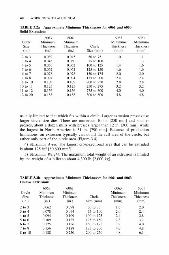
40 WORKING WITH ALUMINUM
TABLE 3.2a Approximate Minimum Thicknesses for 6061 and 6063Solid Extrusions
CircleSize(in.)
6063MinimumThickness
(in.)
6061MinimumThickness
(in.)Circle
Size (mm)
6063MinimumThickness
(mm)
6061MinimumThickness
(mm)
2 to 33 to 44 to 5
0.0390.0450.056
0.0450.0500.062
50 to 7575 to 100
100 to 125
1.01.11.4
1.11.31.6
5 to 6 0.062 0.062 125 to 150 1.6 1.66 to 7 0.078 0.078 150 to 175 2.0 2.07 to 8 0.094 0.094 175 to 200 2.4 2.48 to 10 0.109 0.109 200 to 250 2.8 2.8
10 to 11 0.125 0.125 250 to 275 3.2 3.211 to 12 0.156 0.156 275 to 300 4.0 4.012 to 20 0.188 0.188 300 to 500 4.8 4.8
TABLE 3.2b Approximate Minimum Thicknesses for 6061 and 6063Hollow Extrusions
CircleSize(in.)
6063MinimumThickness
(in.)
6061MinimumThickness
(in.)Circle
Size (mm)
6063MinimumThickness
(mm)
6061MinimumThickness
(mm)
2 to 3 0.062 0.078 50 to 75 1.6 2.03 to 4 0.078 0.094 75 to 100 2.0 2.44 to 5 0.094 0.109 100 to 125 2.4 2.85 to 6 0.109 0.125 125 to 150 2.8 3.26 to 7 0.125 0.156 150 to 175 3.2 4.07 to 8 0.156 0.188 175 to 200 4.0 4.88 to 10 0.188 0.250 200 to 250 4.8 6.3
usually limited to that which fits within a circle. Larger extrusion presses uselarger circle size dies. There are numerous 10 in. [250 mm] and smallerpresses, about a dozen mills with presses larger than 12 in. [300 mm], whilethe largest in North America is 31 in. [790 mm]. Because of productionlimitations, an extrusion typically cannot fill the full area of the circle, butrather only part of the circle area (Figure 3.4).
4) Maximum Area: The largest cross-sectional area that can be extrudedis about 125 in2 [80,600 mm2].
5) Maximum Weight: The maximum total weight of an extrusion is limitedby the weight of a billet to about 4,300 lb [2,000 kg].
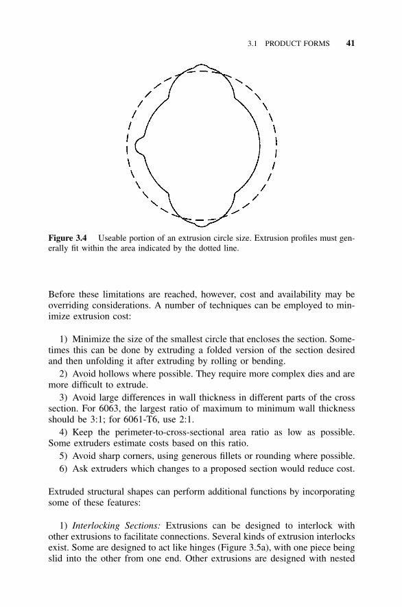
3.1 PRODUCT FORMS 41
Figure 3.4 Useable portion of an extrusion circle size. Extrusion profiles must gen-erally fit within the area indicated by the dotted line.
Before these limitations are reached, however, cost and availability may beoverriding considerations. A number of techniques can be employed to min-imize extrusion cost:
1) Minimize the size of the smallest circle that encloses the section. Some-times this can be done by extruding a folded version of the section desiredand then unfolding it after extruding by rolling or bending.
2) Avoid hollows where possible. They require more complex dies and aremore difficult to extrude.
3) Avoid large differences in wall thickness in different parts of the crosssection. For 6063, the largest ratio of maximum to minimum wall thicknessshould be 3:1; for 6061-T6, use 2:1.
4) Keep the perimeter-to-cross-sectional area ratio as low as possible.Some extruders estimate costs based on this ratio.
5) Avoid sharp corners, using generous fillets or rounding where possible.6) Ask extruders which changes to a proposed section would reduce cost.
Extruded structural shapes can perform additional functions by incorporatingsome of these features:
1) Interlocking Sections: Extrusions can be designed to interlock withother extrusions to facilitate connections. Several kinds of extrusion interlocksexist. Some are designed to act like hinges (Figure 3.5a), with one piece beingslid into the other from one end. Other extrusions are designed with nested
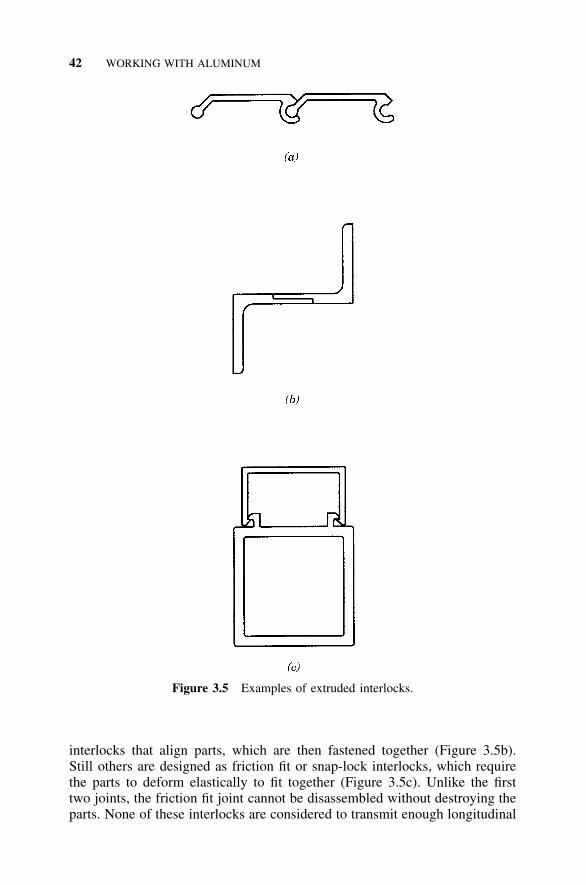
42 WORKING WITH ALUMINUM
Figure 3.5 Examples of extruded interlocks.
interlocks that align parts, which are then fastened together (Figure 3.5b).Still others are designed as friction fit or snap-lock interlocks, which requirethe parts to deform elastically to fit together (Figure 3.5c). Unlike the firsttwo joints, the friction fit joint cannot be disassembled without destroying theparts. None of these interlocks are considered to transmit enough longitudinal
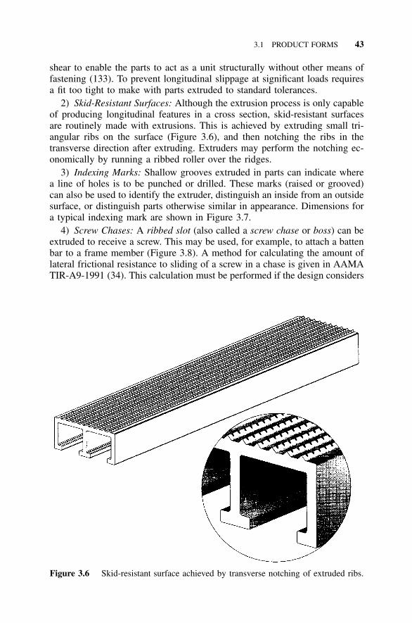
3.1 PRODUCT FORMS 43
Figure 3.6 Skid-resistant surface achieved by transverse notching of extruded ribs.
shear to enable the parts to act as a unit structurally without other means offastening (133). To prevent longitudinal slippage at significant loads requiresa fit too tight to make with parts extruded to standard tolerances.
2) Skid-Resistant Surfaces: Although the extrusion process is only capableof producing longitudinal features in a cross section, skid-resistant surfacesare routinely made with extrusions. This is achieved by extruding small tri-angular ribs on the surface (Figure 3.6), and then notching the ribs in thetransverse direction after extruding. Extruders may perform the notching ec-onomically by running a ribbed roller over the ridges.
3) Indexing Marks: Shallow grooves extruded in parts can indicate wherea line of holes is to be punched or drilled. These marks (raised or grooved)can also be used to identify the extruder, distinguish an inside from an outsidesurface, or distinguish parts otherwise similar in appearance. Dimensions fora typical indexing mark are shown in Figure 3.7.
4) Screw Chases: A ribbed slot (also called a screw chase or boss) can beextruded to receive a screw. This may be used, for example, to attach a battenbar to a frame member (Figure 3.8). A method for calculating the amount oflateral frictional resistance to sliding of a screw in a chase is given in AAMATIR-A9-1991 (34). This calculation must be performed if the design considers
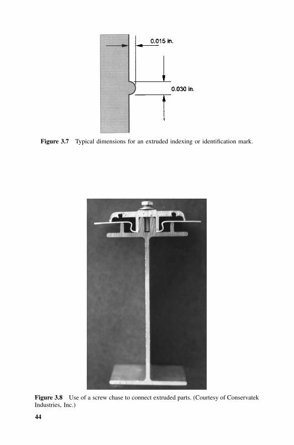
44
Figure 3.7 Typical dimensions for an extruded indexing or identification mark.
Figure 3.8 Use of a screw chase to connect extruded parts. (Courtesy of ConservatekIndustries, Inc.)
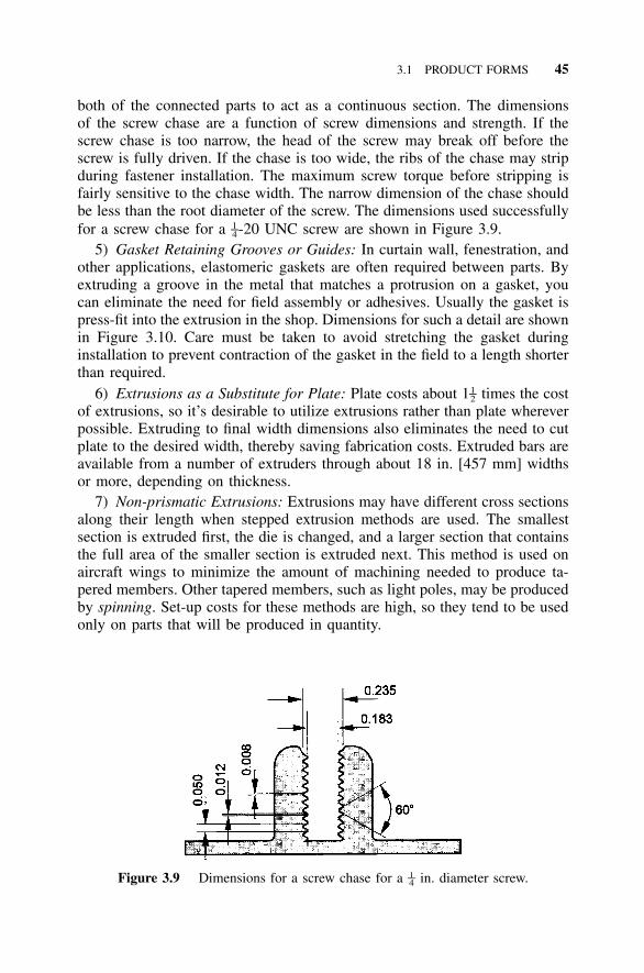
3.1 PRODUCT FORMS 45
Figure 3.9 Dimensions for a screw chase for a in. diameter screw.1–4
both of the connected parts to act as a continuous section. The dimensionsof the screw chase are a function of screw dimensions and strength. If thescrew chase is too narrow, the head of the screw may break off before thescrew is fully driven. If the chase is too wide, the ribs of the chase may stripduring fastener installation. The maximum screw torque before stripping isfairly sensitive to the chase width. The narrow dimension of the chase shouldbe less than the root diameter of the screw. The dimensions used successfullyfor a screw chase for a -20 UNC screw are shown in Figure 3.9.1–4
5) Gasket Retaining Grooves or Guides: In curtain wall, fenestration, andother applications, elastomeric gaskets are often required between parts. Byextruding a groove in the metal that matches a protrusion on a gasket, youcan eliminate the need for field assembly or adhesives. Usually the gasket ispress-fit into the extrusion in the shop. Dimensions for such a detail are shownin Figure 3.10. Care must be taken to avoid stretching the gasket duringinstallation to prevent contraction of the gasket in the field to a length shorterthan required.
6) Extrusions as a Substitute for Plate: Plate costs about 1 times the cost1–2of extrusions, so it’s desirable to utilize extrusions rather than plate whereverpossible. Extruding to final width dimensions also eliminates the need to cutplate to the desired width, thereby saving fabrication costs. Extruded bars areavailable from a number of extruders through about 18 in. [457 mm] widthsor more, depending on thickness.
7) Non-prismatic Extrusions: Extrusions may have different cross sectionsalong their length when stepped extrusion methods are used. The smallestsection is extruded first, the die is changed, and a larger section that containsthe full area of the smaller section is extruded next. This method is used onaircraft wings to minimize the amount of machining needed to produce ta-pered members. Other tapered members, such as light poles, may be producedby spinning. Set-up costs for these methods are high, so they tend to be usedonly on parts that will be produced in quantity.
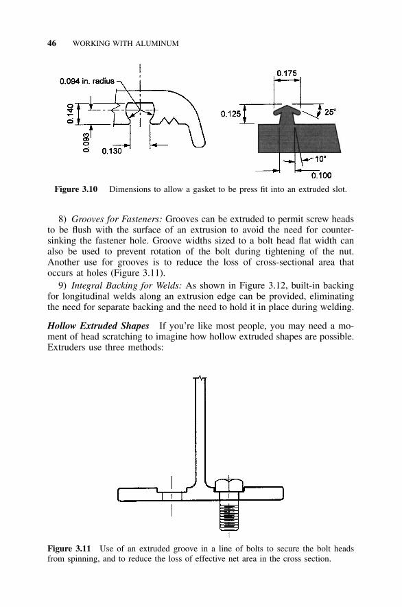
46 WORKING WITH ALUMINUM
Figure 3.10 Dimensions to allow a gasket to be press fit into an extruded slot.
Figure 3.11 Use of an extruded groove in a line of bolts to secure the bolt headsfrom spinning, and to reduce the loss of effective net area in the cross section.
8) Grooves for Fasteners: Grooves can be extruded to permit screw headsto be flush with the surface of an extrusion to avoid the need for counter-sinking the fastener hole. Groove widths sized to a bolt head flat width canalso be used to prevent rotation of the bolt during tightening of the nut.Another use for grooves is to reduce the loss of cross-sectional area thatoccurs at holes (Figure 3.11).
9) Integral Backing for Welds: As shown in Figure 3.12, built-in backingfor longitudinal welds along an extrusion edge can be provided, eliminatingthe need for separate backing and the need to hold it in place during welding.
Hollow Extruded Shapes If you’re like most people, you may need a mo-ment of head scratching to imagine how hollow extruded shapes are possible.Extruders use three methods:
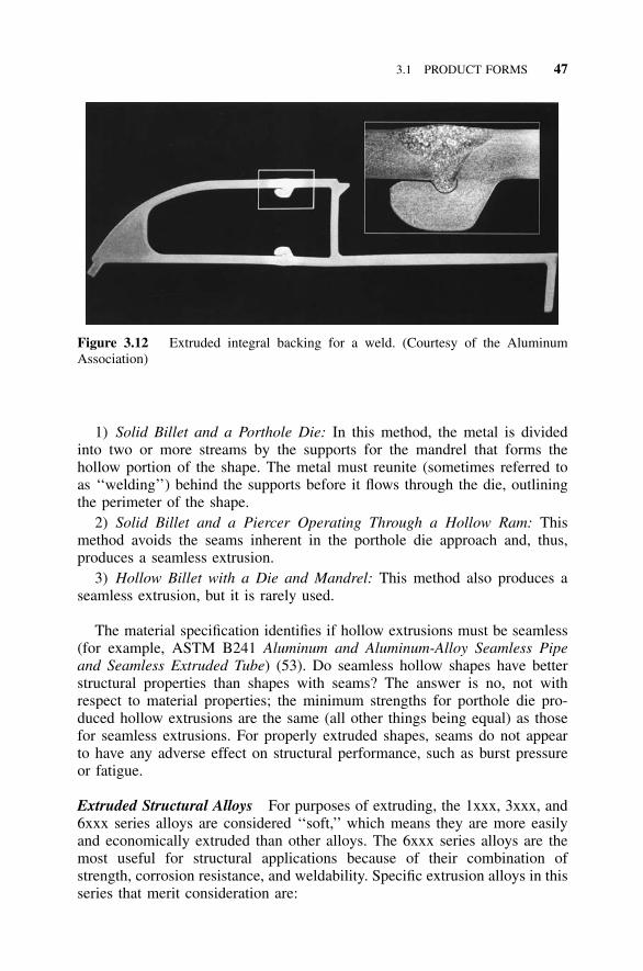
3.1 PRODUCT FORMS 47
Figure 3.12 Extruded integral backing for a weld. (Courtesy of the AluminumAssociation)
1) Solid Billet and a Porthole Die: In this method, the metal is dividedinto two or more streams by the supports for the mandrel that forms thehollow portion of the shape. The metal must reunite (sometimes referred toas ‘‘welding’’) behind the supports before it flows through the die, outliningthe perimeter of the shape.
2) Solid Billet and a Piercer Operating Through a Hollow Ram: Thismethod avoids the seams inherent in the porthole die approach and, thus,produces a seamless extrusion.
3) Hollow Billet with a Die and Mandrel: This method also produces aseamless extrusion, but it is rarely used.
The material specification identifies if hollow extrusions must be seamless(for example, ASTM B241 Aluminum and Aluminum-Alloy Seamless Pipeand Seamless Extruded Tube) (53). Do seamless hollow shapes have betterstructural properties than shapes with seams? The answer is no, not withrespect to material properties; the minimum strengths for porthole die pro-duced hollow extrusions are the same (all other things being equal) as thosefor seamless extrusions. For properly extruded shapes, seams do not appearto have any adverse effect on structural performance, such as burst pressureor fatigue.
Extruded Structural Alloys For purposes of extruding, the 1xxx, 3xxx, and6xxx series alloys are considered ‘‘soft,’’ which means they are more easilyand economically extruded than other alloys. The 6xxx series alloys are themost useful for structural applications because of their combination ofstrength, corrosion resistance, and weldability. Specific extrusion alloys in thisseries that merit consideration are:
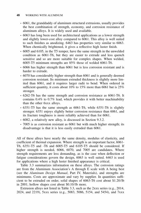
48 WORKING WITH ALUMINUM
• 6061, the granddaddy of aluminum structural extrusions, usually providesthe best combination of strength, economy, and corrosion resistance ofaluminum alloys. It is widely used and available.
• 6063 has long been used for architectural applications as a lower strengthand slightly lower-cost alloy compared to 6061. This alloy is well suitedto such finishes as anodizing. 6463 has properties very similar to 6063.When chemically brightened, it gives a reflective high luster finish.
• 6005 and 6105, in the T5 temper, have the same strength in the unweldedcondition as 6061-T6, but they are easier to extrude and less quenchsensitive and so are more suitable for complex shapes. When welded,6005-T5 minimum strengths are 85% those of welded 6061-T6.
• 6066 has higher strength than 6061 but is less corrosion resistant and isharder to extrude.
• 6070 has considerably higher strength than 6061 and is generally deemedcorrosion resistant. Its minimum extruded thickness is slightly more lim-ited than 6061, and it requires larger radii to bend. When ordered insufficient quantity, it costs about 10% to 15% more than 6061 but is 25%stronger.
• 6262-T6 has the same strength and corrosion resistance as 6061-T6. Itcontains 0.4% to 0.7% lead, which provides it with better machinabilitythan the other 6xxx alloys.
• 6351-T5 has the same strength as 6061-T6, while 6351-T6 is slightlystronger. 6351 enjoys slightly better corrosion resistance than 6061, andits fracture toughness is more reliably achieved than for 6061.
• 6082, a relatively new alloy, is discussed in Section 9.3.2.• 7005 is as corrosion resistant as 6061 but with much higher strength; its
disadvantage is that it is less easily extruded than 6061.
All of these alloys have nearly the same density, modulus of elasticity, andcoefficient of thermal expansion. Where strength is an important factor, 6061-T6, 6351-T5 and -T6 and 6005-T5 and 6105-T5 should be considered. Ifhigher strength is needed, 6066, 6070, and 7005 are candidates. Wherestrength requirements are less demanding, as is the case when deflection orfatigue considerations govern the design, 6063 is well suited. 6463 is usedfor applications where a high luster finished appearance is critical.
Table 3.3 summarizes information on these alloys. The corrosion ratingsare from the Aluminum Association’s A through E scale with A being best(see the Aluminum Design Manual, Part IV, Materials), and strengths areminimums. Costs are approximate and vary by supplier. In quantities suffi-cient to be extruded on order, solid shapes of 6063-T6 cost about $1.20/lbin 2001; hollow shapes cost about $0.10/lb more.
Extrusion alloys not listed in Table 3.3, such as the 2xxx series (e.g., 2014,2024, and 2219), 5xxx series (e.g., 5083, 5086, 5154, and 5454), and 7xxx
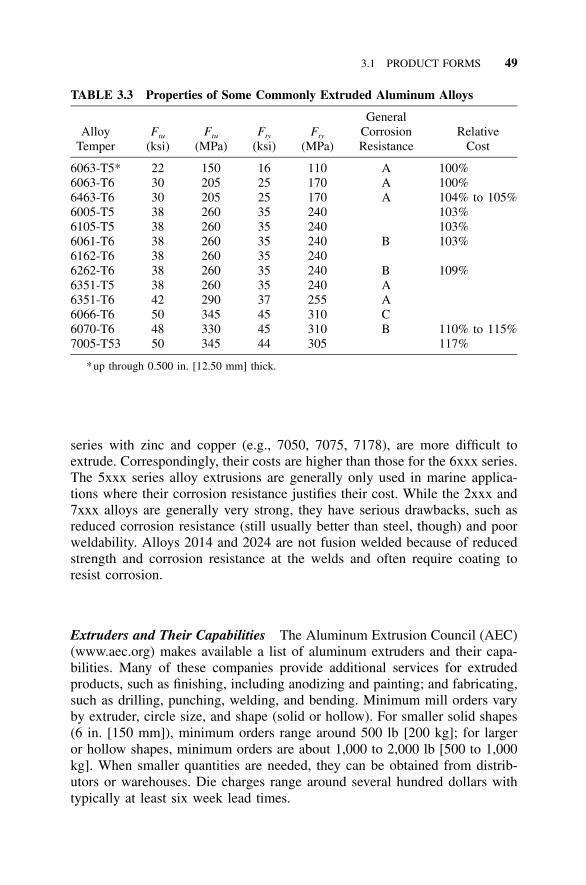
3.1 PRODUCT FORMS 49
TABLE 3.3 Properties of Some Commonly Extruded Aluminum Alloys
AlloyTemper
Ftu
(ksi)Ftu
(MPa)Fty
(ksi)Fty
(MPa)
GeneralCorrosionResistance
RelativeCost
6063-T5* 22 150 16 110 A 100%6063-T6 30 205 25 170 A 100%6463-T6 30 205 25 170 A 104% to 105%6005-T5 38 260 35 240 103%6105-T5 38 260 35 240 103%6061-T6 38 260 35 240 B 103%6162-T6 38 260 35 2406262-T6 38 260 35 240 B 109%6351-T5 38 260 35 240 A6351-T6 42 290 37 255 A6066-T6 50 345 45 310 C6070-T6 48 330 45 310 B 110% to 115%7005-T53 50 345 44 305 117%
*up through 0.500 in. [12.50 mm] thick.
series with zinc and copper (e.g., 7050, 7075, 7178), are more difficult toextrude. Correspondingly, their costs are higher than those for the 6xxx series.The 5xxx series alloy extrusions are generally only used in marine applica-tions where their corrosion resistance justifies their cost. While the 2xxx and7xxx alloys are generally very strong, they have serious drawbacks, such asreduced corrosion resistance (still usually better than steel, though) and poorweldability. Alloys 2014 and 2024 are not fusion welded because of reducedstrength and corrosion resistance at the welds and often require coating toresist corrosion.
Extruders and Their Capabilities The Aluminum Extrusion Council (AEC)(www.aec.org) makes available a list of aluminum extruders and their capa-bilities. Many of these companies provide additional services for extrudedproducts, such as finishing, including anodizing and painting; and fabricating,such as drilling, punching, welding, and bending. Minimum mill orders varyby extruder, circle size, and shape (solid or hollow). For smaller solid shapes(6 in. [150 mm]), minimum orders range around 500 lb [200 kg]; for largeror hollow shapes, minimum orders are about 1,000 to 2,000 lb [500 to 1,000kg]. When smaller quantities are needed, they can be obtained from distrib-utors or warehouses. Die charges range around several hundred dollars withtypically at least six week lead times.
50 WORKING WITH ALUMINUM
Extrusion Tolerances Standard extrusion cross-sectional dimensional tol-erances have been established and are published by the Aluminum Associa-tion. They are given in Table 3.4. For other tolerances (such as length,straightness, twist, flatness of flat surfaces, surface roughness, contour ofcurved surfaces, squareness of cut ends, corner and fillet radii, and angularity)consult Aluminum Standards and Data (11). Determining extrusion tolerancescan be more complicated than you’d think, so you may want to consult yourextruder. Closer tolerances can be held at increased cost; most extrusions canbe ordered to tolerances that are one-half the Aluminum Standards and Datavalues. The 5xxx series alloys have larger tolerances than other extrudedalloys.
Fabrication For many applications, extrusions require little additional fab-rication once they’ve been shipped from the mill. Typical processes involvecutting to length and fabricating holes. Extrusions may also be rolled to takeon curvature for camber or other purposes. However, if strains required bythe rolling process are great enough, they may produce cracking. This situ-ation can sometimes be avoided by rolling before the material is artificiallyaged. For example, 6061 extrusions can be rolled in the -T4 temper and thenartificially aged at the mill to the -T6 temper, which is usually needed forstrength in the finished member. The -T4 temper has a minimum elongationof 16% versus 8% for the -T6 temper, so cracking is more readily avoidedthis way.
Extrusion Quality Assurance Extrusion mills will generally supply certifi-cation meeting Aluminum Association requirements at no additional chargeif this is requested when the material is ordered. The number of samples formechanical tests is determined as follows: for extrusions weighing less than1 lb/ft [1.7 kg/m], one sample is taken for each 1,000 lb. [500 kg], or fractionthereof, in a lot; for extrusions weighing 1 lb/ft [1.7 kg/m] or more, onesample is taken for each 1,000 ft [300 m], or part thereof, in a lot. Tensiontests are made for the longitudinal direction only, unless other prior agreementis made with the supplier. The tensile yield strength, tensile ultimate strength,and elongation are reported and must meet or exceed the minimum valuesfor these properties established in Aluminum Standards and Data.
Purchasers of extrusions ordered in mill quantities for building structuresoften do not require identification marking. (Indexing, or identification, marks[see above] extruded into the shape are, therefore, particularly useful to keeptrack of producer and alloy.) Extruded structural shapes purchased from awarehouse usually have identification marking consisting of the producer andthe alloy and temper. Suppliers may provide either continuous (at intervalsno greater than 40 in. [1,000 mm] along the length) or spot (once per piece)marking.
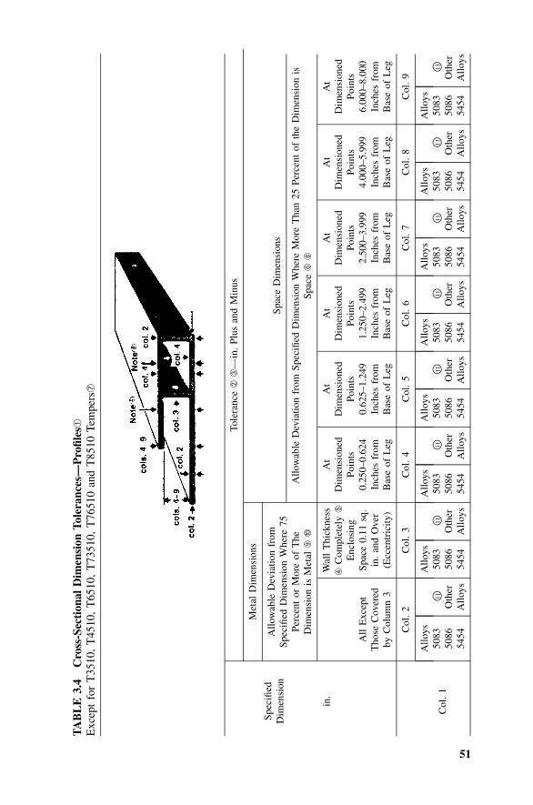
51
TA
BL
E3.
4C
ross
-Sec
tion
alD
imen
sion
Tol
eran
ces—
Pro
files
➀
Exc
ept
for
T35
10,
T45
10,
T65
10,
T73
510,
T76
510
and
T85
10Te
mpe
rs➆
Spec
ified
Dim
ensi
on
Tole
ranc
e➁
➂—
in.
Plus
and
Min
us
Met
alD
imen
sion
s
Allo
wab
leD
evia
tion
from
Spec
ified
Dim
ensi
onW
here
75Pe
rcen
tor
Mor
eof
The
Dim
ensi
onis
Met
al➈
➉
Spac
eD
imen
sion
s
Allo
wab
leD
evia
tion
from
Spec
ified
Dim
ensi
onW
here
Mor
eT
han
25Pe
rcen
tof
the
Dim
ensi
onis
Spac
e➅
➇
in.
All
Exc
ept
Tho
seC
over
edby
Col
umn
3
Wal
lT
hick
ness
➃C
ompl
etel
y➄
Enc
losi
ngSp
ace
0.11
sq.
in.
and
Ove
r(E
ccen
tric
ity)
At
Dim
ensi
oned
Poin
ts0.
250–
0.62
4In
ches
from
Bas
eof
Leg
At
Dim
ensi
oned
Poin
ts0.
625–
1.24
9In
ches
from
Bas
eof
Leg
At
Dim
ensi
oned
Poin
ts1.
250–
2.49
9In
ches
from
Bas
eof
Leg
At
Dim
ensi
oned
Poin
ts2.
500–
3.99
9In
ches
from
Bas
eof
Leg
At
Dim
ensi
oned
Poin
ts4.
000–
5.99
9In
ches
from
Bas
eof
Leg
At
Dim
ensi
oned
Poin
ts6.
000–
8.00
0In
ches
from
Bas
eof
Leg
Col
.2
Col
.3
Col
.4
Col
.5
Col
.6
Col
.7
Col
.8
Col
.9
Col
.1
Allo
ys50
8350
8654
54
�11
Oth
erA
lloys
Allo
ys50
8350
8654
54
�11
Oth
erA
lloys
Allo
ys50
8350
8654
54
�11
Oth
erA
lloys
Allo
ys50
8350
8654
54
�11
Oth
erA
lloys
Allo
ys50
8350
8654
54
�11
Oth
erA
lloys
Allo
ys50
8350
8654
54
�11
Oth
erA
lloys
Allo
ys50
8350
8654
54
�11
Oth
erA
lloys
Allo
ys50
8350
8654
54
�11
Oth
erA
lloys
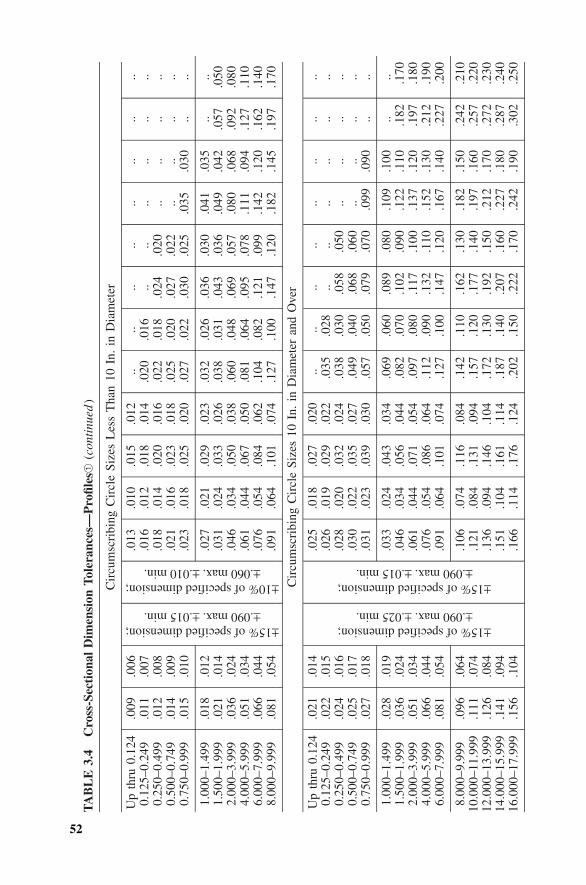
52
TA
BL
E3.
4C
ross
-Sec
tion
alD
imen
sion
Tol
eran
ces—
Pro
files
➀(c
onti
nued
)
Cir
cum
scri
bing
Cir
cle
Size
sL
ess
Tha
n10
In.
inD
iam
eter
Up
thru
0.12
40.
125–
0.24
90.
250–
0.49
90.
500–
0.74
90.
750–
0.99
9
1.00
0–1.
499
1.50
0–1.
999
2.00
0–3.
999
4.00
0–5.
999
6.00
0–7.
999
8.00
0–9.
999
.009
.011
.012
.014
.015
.018
.021
.036
.051
.066
.081
.006
.007
.008
.009
.010
.012
.014
.024
.034
.044
.054
.013
.016
.018
.021
.023
.027
.031
.046
.061
.076
.091
.010
.012
.014
.016
.018
.021
.024
.034
.044
.054
.064
.015
.018
.020
.023
.025
.029
.033
.050
.067
.084
.101
.012
.014
.016
.018
.020
.023
.026
.038
.050
.062
.074
...0
20.0
22.0
25.0
27
.032
.038
.060
.081
.104
.127
...0
16.0
18.0
20.0
22
.026
.031
.048
.064
.082
.100
.. ...0
24.0
27.0
30
.036
.043
.069
.095
.121
.147
.. ...0
20.0
22.0
25
.030
.036
.057
.078
.099
.120
.. .. .. ...0
35
.041
.049
.080
.111
.142
.182
.. .. .. ...0
30
.035
.042
.068
.094
.120
.145
.. .. .. .. .. ...0
57.0
92.1
27.1
62.1
97
.. .. .. .. .. ...0
50.0
80.1
10.1
40.1
70
Cir
cum
scri
bing
Cir
cle
Size
s10
In.
inD
iam
eter
and
Ove
r
Up
thru
0.12
40.
125–
0.24
90.
250–
0.49
90.
500–
0.74
90.
750–
0.99
9
1.00
0–1.
499
1.50
0–1.
999
2.00
0–3.
999
4.00
0–5.
999
6.00
0–7.
999
8.00
0–9.
999
10.0
00–1
1.99
912
.000
–13.
999
14.0
00–1
5.99
916
.000
–17.
999
.021
.022
.024
.025
.027
.028
.036
.051
.066
.081
.096
.111
.126
.141
.156
.014
.015
.016
.017
.018
.019
.024
.034
.044
.054
.064
.074
.084
.094
.104
±15% of specified dimension;±.090 max. ±.025 min.
±15% of specified dimension;±.090 max. ±.015 min.
±15% of specified dimension;±.090 max. ±.015 min.
±10% of specified dimension;±.060 max. ±.010 min.
.025
.026
.028
.030
.031
.033
.046
.061
.076
.091
.106
.121
.136
.151
.166
.018
.019
.020
.022
.023
.024
.034
.044
.054
.064
.074
.084
.094
.104
.114
.027
.029
.032
.035
.039
.043
.056
.071
.086
.101
.116
.131
.146
.161
.176
.020
.022
.024
.027
.030
.034
.044
.054
.064
.074
.084
.094
.104
.114
.124
.. .035
.038
.049
.057
.069
.082
.097
.112
.127
.142
.157
.172
.187
.202
.. .028
.030
.040
.050
.060
.070
.080
.090
.100
.110
.120
.130
.140
.150
.. .. .058
.068
.079
.089
.102
.117
.132
.147
.162
.177
.192
.207
.222
.. .. .050
.060
.070
.080
.090
.100
.110
.120
.130
.140
.150
.160
.170
.. .. .. .. .099
.109
.122
.137
.152
.167
.182
.197
.212
.227
.242
.. .. .. ...0
90
.100
.110
.120
.130
.140
.150
.160
.170
.180
.190
.. .. .. .. .. .. .182
.197
.212
.227
.242
.257
.272
.287
.302
.. .. .. .. .. .. .170
.180
.190
.200
.210
.220
.230
.240
.250
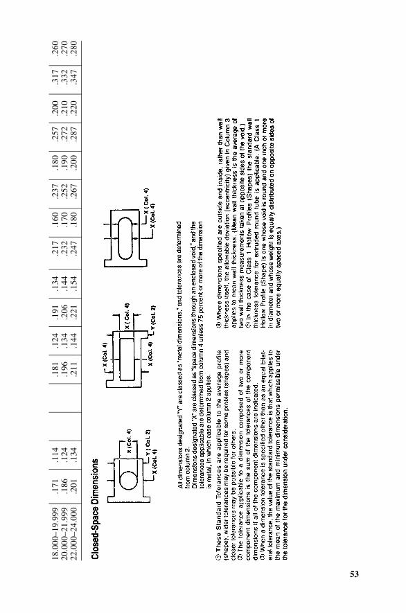
53
18.0
00–1
9.99
920
.000
–21.
999
22.0
00–2
4.00
0
.171
.186
.201
.114
.124
.134
.181
.196
.211
.124
.134
.144
.191
.206
.221
.134
.144
.154
.217
.232
.247
.160
.170
.180
.237
.252
.267
.180
.190
.200
.257
.272
.287
.200
.210
.220
.317
.332
.347
.260
.270
.280
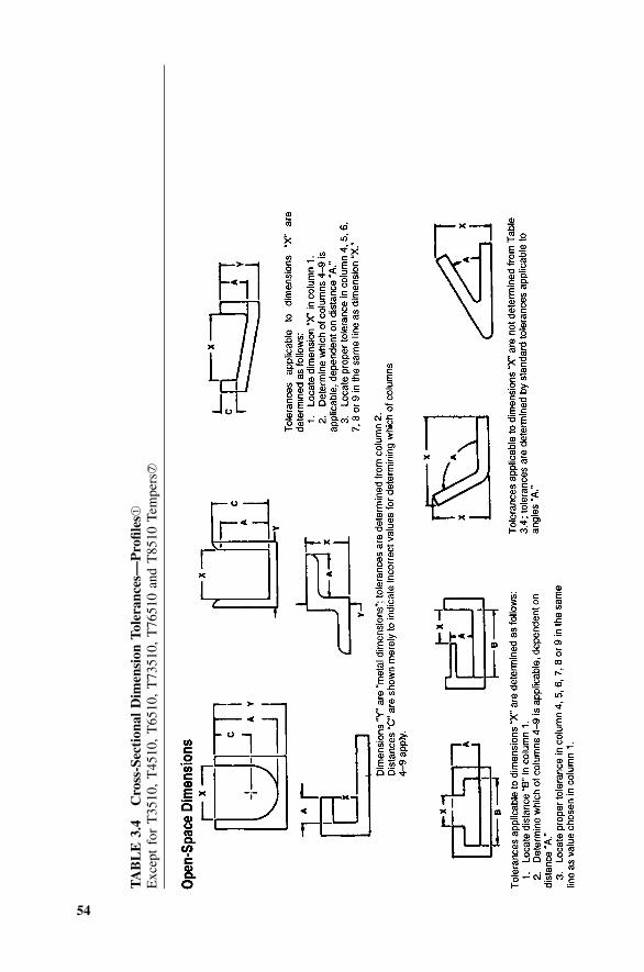
54
TA
BL
E3.
4C
ross
-Sec
tion
alD
imen
sion
Tol
eran
ces—
Pro
files
➀
Exc
ept
for
T35
10,
T45
10,
T65
10,
T73
510,
T76
510
and
T85
10Te
mpe
rs➆
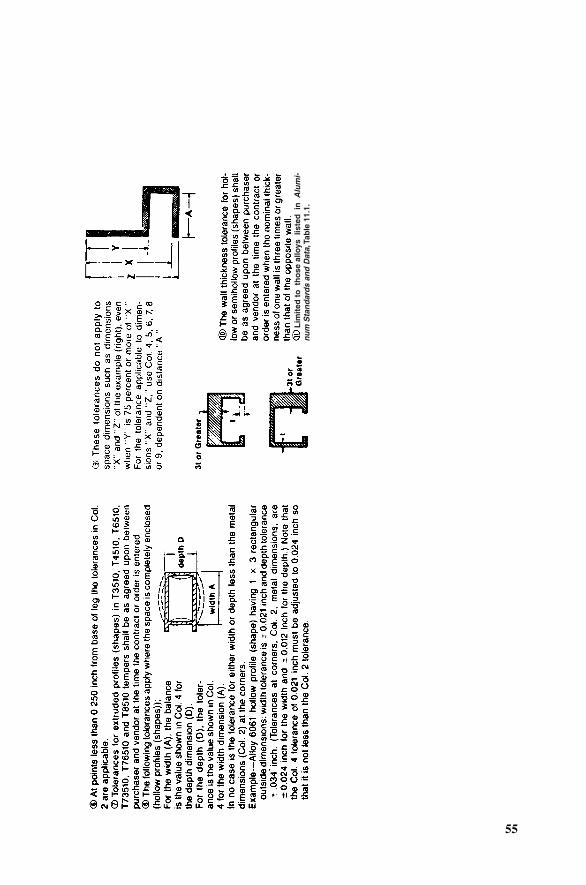
55
Lim
ited
to
th
ose
allo
ys l
iste
d i
n A
lum
i-n
um
Sta
nd
ard
s an
d D
ata,
Tab
le 1
1.1.
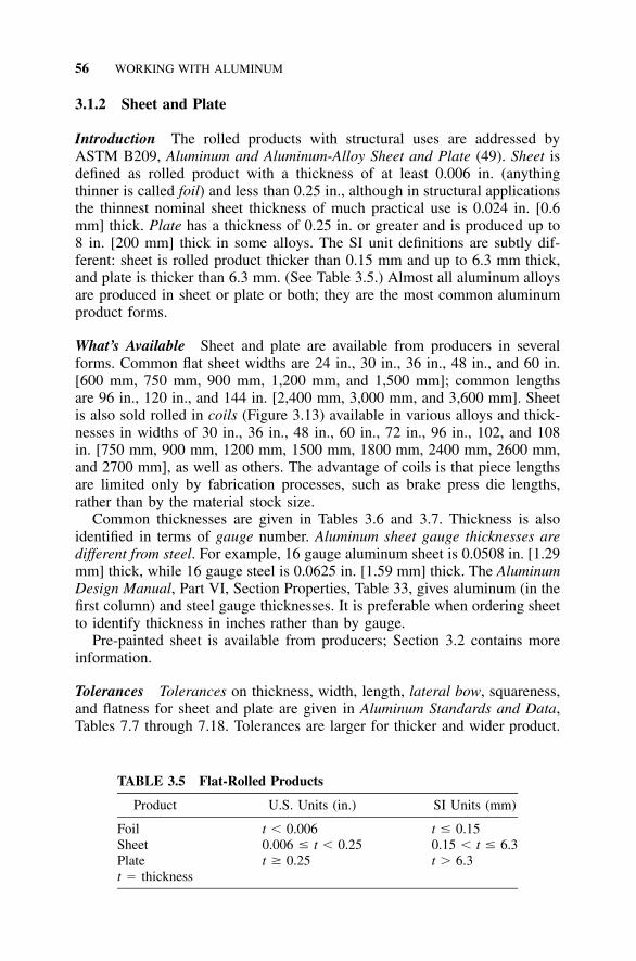
56 WORKING WITH ALUMINUM
TABLE 3.5 Flat-Rolled Products
Product U.S. Units (in.) SI Units (mm)
Foil t � 0.006 t � 0.15Sheet 0.006 � t � 0.25 0.15 � t � 6.3Plate t � 0.25 t � 6.3t � thickness
3.1.2 Sheet and Plate
Introduction The rolled products with structural uses are addressed byASTM B209, Aluminum and Aluminum-Alloy Sheet and Plate (49). Sheet isdefined as rolled product with a thickness of at least 0.006 in. (anythingthinner is called foil) and less than 0.25 in., although in structural applicationsthe thinnest nominal sheet thickness of much practical use is 0.024 in. [0.6mm] thick. Plate has a thickness of 0.25 in. or greater and is produced up to8 in. [200 mm] thick in some alloys. The SI unit definitions are subtly dif-ferent: sheet is rolled product thicker than 0.15 mm and up to 6.3 mm thick,and plate is thicker than 6.3 mm. (See Table 3.5.) Almost all aluminum alloysare produced in sheet or plate or both; they are the most common aluminumproduct forms.
What’s Available Sheet and plate are available from producers in severalforms. Common flat sheet widths are 24 in., 30 in., 36 in., 48 in., and 60 in.[600 mm, 750 mm, 900 mm, 1,200 mm, and 1,500 mm]; common lengthsare 96 in., 120 in., and 144 in. [2,400 mm, 3,000 mm, and 3,600 mm]. Sheetis also sold rolled in coils (Figure 3.13) available in various alloys and thick-nesses in widths of 30 in., 36 in., 48 in., 60 in., 72 in., 96 in., 102, and 108in. [750 mm, 900 mm, 1200 mm, 1500 mm, 1800 mm, 2400 mm, 2600 mm,and 2700 mm], as well as others. The advantage of coils is that piece lengthsare limited only by fabrication processes, such as brake press die lengths,rather than by the material stock size.
Common thicknesses are given in Tables 3.6 and 3.7. Thickness is alsoidentified in terms of gauge number. Aluminum sheet gauge thicknesses aredifferent from steel. For example, 16 gauge aluminum sheet is 0.0508 in. [1.29mm] thick, while 16 gauge steel is 0.0625 in. [1.59 mm] thick. The AluminumDesign Manual, Part VI, Section Properties, Table 33, gives aluminum (in thefirst column) and steel gauge thicknesses. It is preferable when ordering sheetto identify thickness in inches rather than by gauge.
Pre-painted sheet is available from producers; Section 3.2 contains moreinformation.
Tolerances Tolerances on thickness, width, length, lateral bow, squareness,and flatness for sheet and plate are given in Aluminum Standards and Data,Tables 7.7 through 7.18. Tolerances are larger for thicker and wider product.
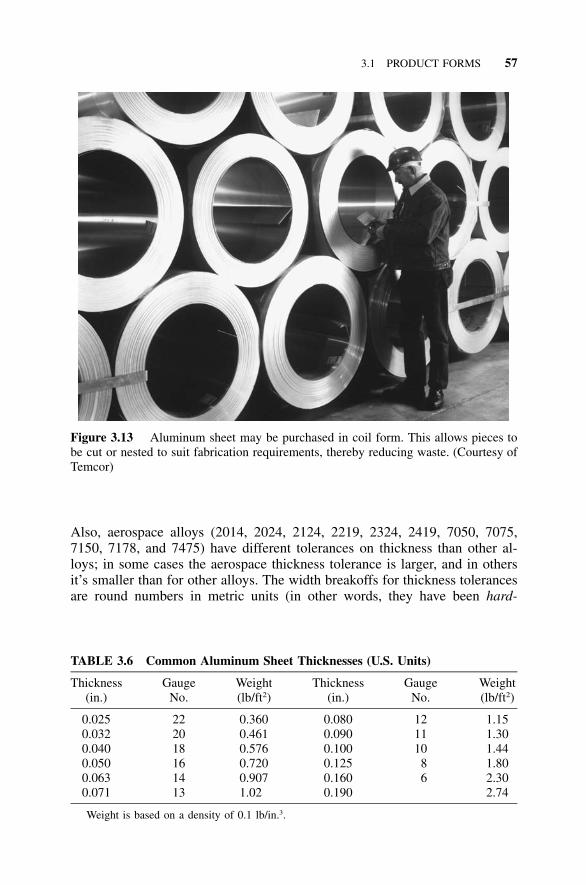
3.1 PRODUCT FORMS 57
Figure 3.13 Aluminum sheet may be purchased in coil form. This allows pieces tobe cut or nested to suit fabrication requirements, thereby reducing waste. (Courtesy ofTemcor)
TABLE 3.6 Common Aluminum Sheet Thicknesses (U.S. Units)
Thickness(in.)
GaugeNo.
Weight(lb/ft2)
Thickness(in.)
GaugeNo.
Weight(lb/ft2)
0.025 22 0.360 0.080 12 1.150.032 20 0.461 0.090 11 1.300.040 18 0.576 0.100 10 1.440.050 16 0.720 0.125 8 1.800.063 14 0.907 0.160 6 2.300.071 13 1.02 0.190 2.74
Weight is based on a density of 0.1 lb/in.3.
Also, aerospace alloys (2014, 2024, 2124, 2219, 2324, 2419, 7050, 7075,7150, 7178, and 7475) have different tolerances on thickness than other al-loys; in some cases the aerospace thickness tolerance is larger, and in othersit’s smaller than for other alloys. The width breakoffs for thickness tolerancesare round numbers in metric units (in other words, they have been hard-
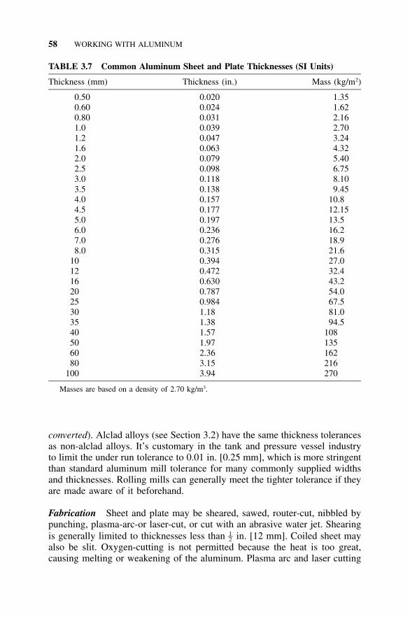
58 WORKING WITH ALUMINUM
TABLE 3.7 Common Aluminum Sheet and Plate Thicknesses (SI Units)
Thickness (mm) Thickness (in.) Mass (kg/m2)
0.50 0.020 1.350.60 0.024 1.620.80 0.031 2.161.0 0.039 2.701.2 0.047 3.241.6 0.063 4.322.0 0.079 5.402.5 0.098 6.753.0 0.118 8.103.5 0.138 9.454.0 0.157 10.84.5 0.177 12.155.0 0.197 13.56.0 0.236 16.27.0 0.276 18.98.0 0.315 21.6
10 0.394 27.012 0.472 32.416 0.630 43.220 0.787 54.025 0.984 67.530 1.18 81.035 1.38 94.540 1.57 10850 1.97 13560 2.36 16280 3.15 216
100 3.94 270
Masses are based on a density of 2.70 kg/m3.
converted). Alclad alloys (see Section 3.2) have the same thickness tolerancesas non-alclad alloys. It’s customary in the tank and pressure vessel industryto limit the under run tolerance to 0.01 in. [0.25 mm], which is more stringentthan standard aluminum mill tolerance for many commonly supplied widthsand thicknesses. Rolling mills can generally meet the tighter tolerance if theyare made aware of it beforehand.
Fabrication Sheet and plate may be sheared, sawed, router-cut, nibbled bypunching, plasma-arc-or laser-cut, or cut with an abrasive water jet. Shearingis generally limited to thicknesses less than in. [12 mm]. Coiled sheet may1–2also be slit. Oxygen-cutting is not permitted because the heat is too great,causing melting or weakening of the aluminum. Plasma arc and laser cutting
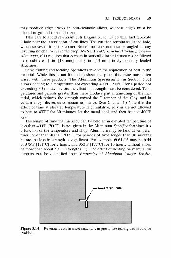
3.1 PRODUCT FORMS 59
Figure 3.14 Re-entrant cuts in sheet material can precipitate tearing and should beavoided.
may produce edge cracks in heat-treatable alloys, so these edges must beplaned or ground to sound metal.
Take care to avoid re-entrant cuts (Figure 3.14). To do this, first fabricatea hole near the intersection of cut lines. The cut then terminates at the hole,which serves to fillet the corner. Sometimes cuts can also be angled so anyresulting notches occur in the drop. AWS D1.2-97, Structural Welding Code—Aluminum, (91) requires that corners in statically loaded structures be filletedto a radius of in. [13 mm] and in. [19 mm] in dynamically loaded1 3– –2 4
structures.Some cutting and forming operations involve the application of heat to the
material. While this is not limited to sheet and plate, this issue most oftenarises with these products. The Aluminum Specification (in Section 6.3a)allows heating to a temperature not exceeding 400�F [200�C] for a period notexceeding 30 minutes before the effect on strength must be considered. Tem-peratures and periods greater than these produce partial annealing of the ma-terial, which reduces the strength toward the O temper of the alloy, and incertain alloys decreases corrosion resistance. (See Chapter 4.) Note that theeffect of time at elevated temperature is cumulative, so you are not allowedto heat to 400�F for 30 minutes, let the metal cool, and then heat to 400�Fagain.
The length of time that an alloy can be held at an elevated temperature ofless than 400�F [200�C] is not given in the Aluminum Specification since it’sa function of the temperature and alloy. Aluminum may be held at tempera-tures lower than 400�F [200�C] for periods of time longer than 30 minutesbefore the loss in strength is significant. For example, 6061-T6 may be heldat 375�F [191�C] for 2 hours, and 350�F [177�C] for 10 hours, without a lossof more than about 5% in strengths (1). The effect of heating on many alloytempers can be quantified from Properties of Aluminum Alloys: Tensile,
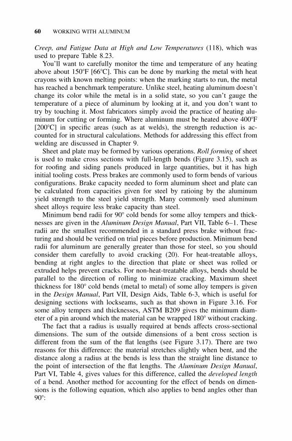
60 WORKING WITH ALUMINUM
Creep, and Fatigue Data at High and Low Temperatures (118), which wasused to prepare Table 8.23.
You’ll want to carefully monitor the time and temperature of any heatingabove about 150�F [66�C]. This can be done by marking the metal with heatcrayons with known melting points: when the marking starts to run, the metalhas reached a benchmark temperature. Unlike steel, heating aluminum doesn’tchange its color while the metal is in a solid state, so you can’t gauge thetemperature of a piece of aluminum by looking at it, and you don’t want totry by touching it. Most fabricators simply avoid the practice of heating alu-minum for cutting or forming. Where aluminum must be heated above 400�F[200�C] in specific areas (such as at welds), the strength reduction is ac-counted for in structural calculations. Methods for addressing this effect fromwelding are discussed in Chapter 9.
Sheet and plate may be formed by various operations. Roll forming of sheetis used to make cross sections with full-length bends (Figure 3.15), such asfor roofing and siding panels produced in large quantities, but it has highinitial tooling costs. Press brakes are commonly used to form bends of variousconfigurations. Brake capacity needed to form aluminum sheet and plate canbe calculated from capacities given for steel by ratioing by the aluminumyield strength to the steel yield strength. Many commonly used aluminumsheet alloys require less brake capacity than steel.
Minimum bend radii for 90� cold bends for some alloy tempers and thick-nesses are given in the Aluminum Design Manual, Part VII, Table 6–1. Theseradii are the smallest recommended in a standard press brake without frac-turing and should be verified on trial pieces before production. Minimum bendradii for aluminum are generally greater than those for steel, so you shouldconsider them carefully to avoid cracking (20). For heat-treatable alloys,bending at right angles to the direction that plate or sheet was rolled orextruded helps prevent cracks. For non-heat-treatable alloys, bends should beparallel to the direction of rolling to minimize cracking. Maximum sheetthickness for 180� cold bends (metal to metal) of some alloy tempers is givenin the Design Manual, Part VII, Design Aids, Table 6-3, which is useful fordesigning sections with lockseams, such as that shown in Figure 3.16. Forsome alloy tempers and thicknesses, ASTM B209 gives the minimum diam-eter of a pin around which the material can be wrapped 180� without cracking.
The fact that a radius is usually required at bends affects cross-sectionaldimensions. The sum of the outside dimensions of a bent cross section isdifferent from the sum of the flat lengths (see Figure 3.17). There are tworeasons for this difference: the material stretches slightly when bent, and thedistance along a radius at the bends is less than the straight line distance tothe point of intersection of the flat lengths. The Aluminum Design Manual,Part VI, Table 4, gives values for this difference, called the developed lengthof a bend. Another method for accounting for the effect of bends on dimen-sions is the following equation, which also applies to bend angles other than90�:
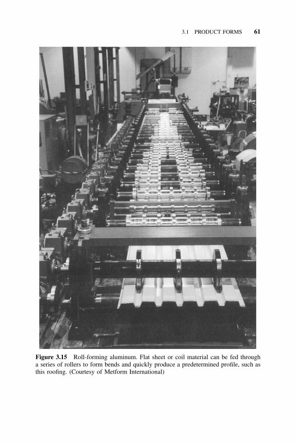
3.1 PRODUCT FORMS 61
Figure 3.15 Roll-forming aluminum. Flat sheet or coil material can be fed througha series of rollers to form bends and quickly produce a predetermined profile, such asthis roofing. (Courtesy of Metform International)
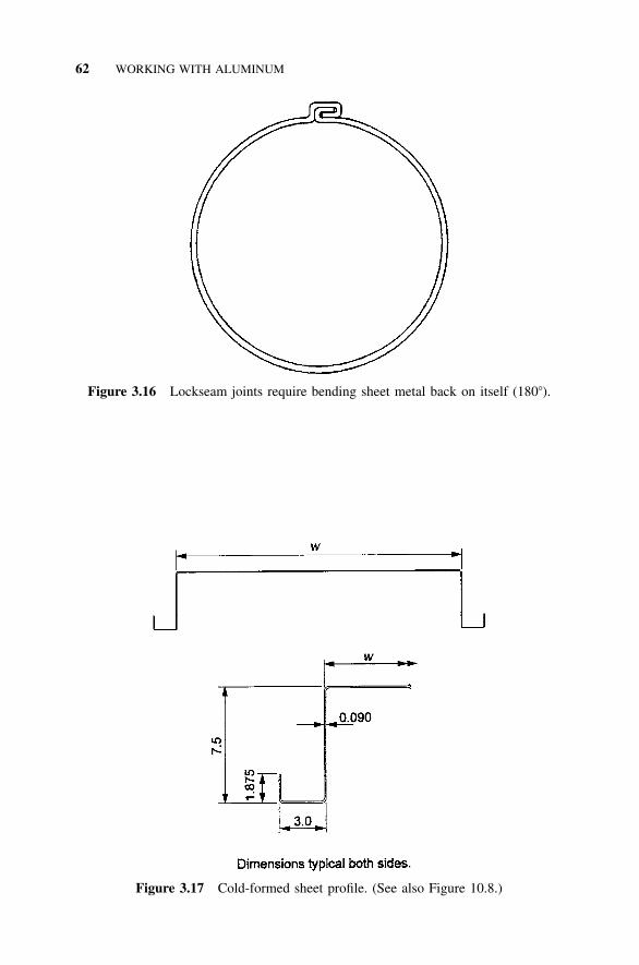
62 WORKING WITH ALUMINUM
Figure 3.16 Lockseam joints require bending sheet metal back on itself (180�).
Figure 3.17 Cold-formed sheet profile. (See also Figure 10.8.)
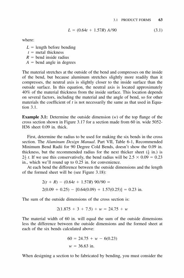
3.1 PRODUCT FORMS 63
L � (0.64t � 1.57R) A /90 (3.1)
where:
L � length before bendingt � metal thickness
R � bend inside radiusA � bend angle in degrees
The material stretches at the outside of the bend and compresses on the insideof the bend, but because aluminum stretches slightly more readily than itcompresses, the neutral axis is slightly closer to the inside surface than theoutside surface. In this equation, the neutral axis is located approximately40% of the material thickness from the inside surface. This location dependson several factors, including the material and the angle of bend, so for othermaterials the coefficient of t is not necessarily the same as that used in Equa-tion 3.1.
Example 3.1: Determine the outside dimension (w) of the top flange of thecross section shown in Figure 3.17 for a section made from 60 in. wide 5052-H36 sheet 0.09 in. thick.
First, determine the radius to be used for making the six bends in the crosssection. The Aluminum Design Manual. Part VII, Table 6-1, RecommendedMinimum Bend Radii for 90 Degree Cold Bends, doesn’t show the 0.09 in.thickness, but the recommended radius for the next thicker sheet ( in.) is1–82 t. If we use this conservatively, the bend radius will be 2.5 � 0.09 � 0.231–2in., which we’ll round up to 0.25 in. for convenience.
At each bend the difference between the outside dimensions and the lengthof the formed sheet will be (see Figure 3.18):
2(t � R) � (0.64t � 1.57R) 90/90 �
2(0.09 � 0.25) � [0.64(0.09) � 1.57(0.25)] � 0.23 in.
The sum of the outside dimensions of the cross section is:
2(1.875 � 3 � 7.5) � w � 24.75 � w
The material width of 60 in. will equal the sum of the outside dimensionsless the difference between the outside dimensions and the formed sheet ateach of the six bends calculated above:
60 � 24.75 � w � 6(0.23)
w � 36.63 in.
When designing a section to be fabricated by bending, you must consider the
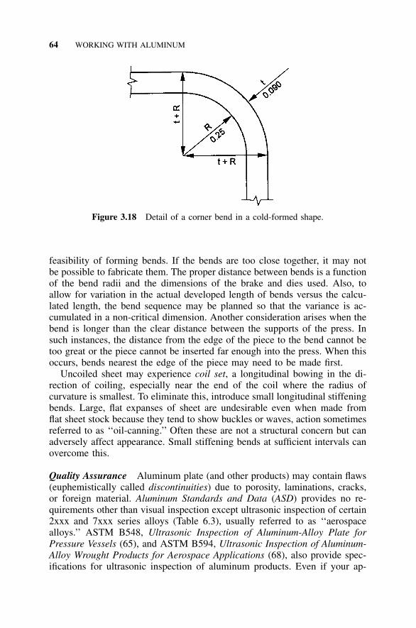
64 WORKING WITH ALUMINUM
Figure 3.18 Detail of a corner bend in a cold-formed shape.
feasibility of forming bends. If the bends are too close together, it may notbe possible to fabricate them. The proper distance between bends is a functionof the bend radii and the dimensions of the brake and dies used. Also, toallow for variation in the actual developed length of bends versus the calcu-lated length, the bend sequence may be planned so that the variance is ac-cumulated in a non-critical dimension. Another consideration arises when thebend is longer than the clear distance between the supports of the press. Insuch instances, the distance from the edge of the piece to the bend cannot betoo great or the piece cannot be inserted far enough into the press. When thisoccurs, bends nearest the edge of the piece may need to be made first.
Uncoiled sheet may experience coil set, a longitudinal bowing in the di-rection of coiling, especially near the end of the coil where the radius ofcurvature is smallest. To eliminate this, introduce small longitudinal stiffeningbends. Large, flat expanses of sheet are undesirable even when made fromflat sheet stock because they tend to show buckles or waves, action sometimesreferred to as ‘‘oil-canning.’’ Often these are not a structural concern but canadversely affect appearance. Small stiffening bends at sufficient intervals canovercome this.
Quality Assurance Aluminum plate (and other products) may contain flaws(euphemistically called discontinuities) due to porosity, laminations, cracks,or foreign material. Aluminum Standards and Data (ASD) provides no re-quirements other than visual inspection except ultrasonic inspection of certain2xxx and 7xxx series alloys (Table 6.3), usually referred to as ‘‘aerospacealloys.’’ ASTM B548, Ultrasonic Inspection of Aluminum-Alloy Plate forPressure Vessels (65), and ASTM B594, Ultrasonic Inspection of Aluminum-Alloy Wrought Products for Aerospace Applications (68), also provide spec-ifications for ultrasonic inspection of aluminum products. Even if your ap-
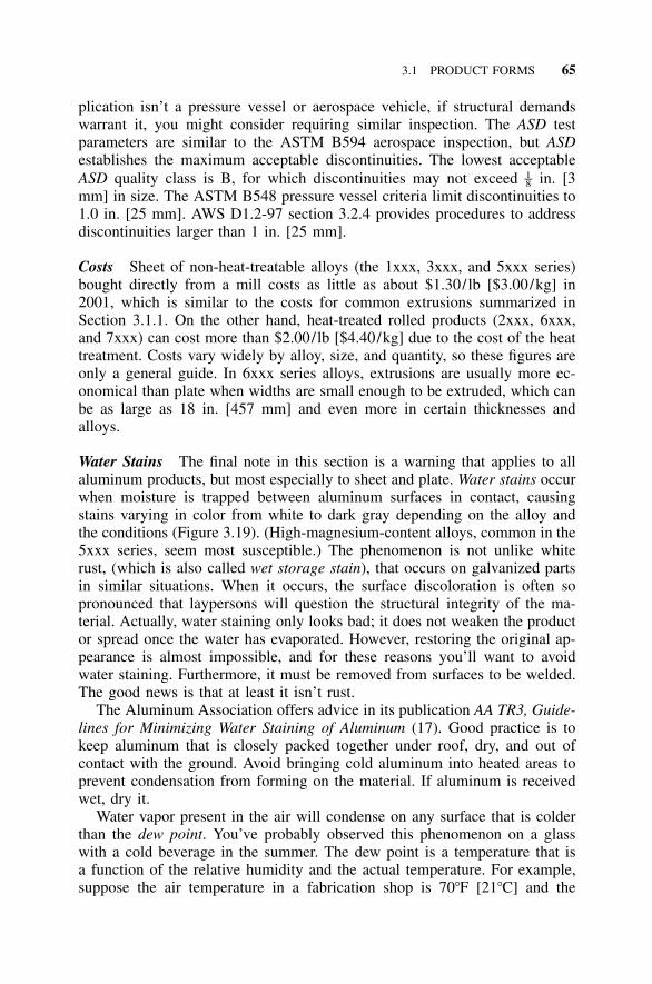
3.1 PRODUCT FORMS 65
plication isn’t a pressure vessel or aerospace vehicle, if structural demandswarrant it, you might consider requiring similar inspection. The ASD testparameters are similar to the ASTM B594 aerospace inspection, but ASDestablishes the maximum acceptable discontinuities. The lowest acceptableASD quality class is B, for which discontinuities may not exceed in. [31–8mm] in size. The ASTM B548 pressure vessel criteria limit discontinuities to1.0 in. [25 mm]. AWS D1.2-97 section 3.2.4 provides procedures to addressdiscontinuities larger than 1 in. [25 mm].
Costs Sheet of non-heat-treatable alloys (the 1xxx, 3xxx, and 5xxx series)bought directly from a mill costs as little as about $1.30/lb [$3.00/kg] in2001, which is similar to the costs for common extrusions summarized inSection 3.1.1. On the other hand, heat-treated rolled products (2xxx, 6xxx,and 7xxx) can cost more than $2.00/lb [$4.40/kg] due to the cost of the heattreatment. Costs vary widely by alloy, size, and quantity, so these figures areonly a general guide. In 6xxx series alloys, extrusions are usually more ec-onomical than plate when widths are small enough to be extruded, which canbe as large as 18 in. [457 mm] and even more in certain thicknesses andalloys.
Water Stains The final note in this section is a warning that applies to allaluminum products, but most especially to sheet and plate. Water stains occurwhen moisture is trapped between aluminum surfaces in contact, causingstains varying in color from white to dark gray depending on the alloy andthe conditions (Figure 3.19). (High-magnesium-content alloys, common in the5xxx series, seem most susceptible.) The phenomenon is not unlike whiterust, (which is also called wet storage stain), that occurs on galvanized partsin similar situations. When it occurs, the surface discoloration is often sopronounced that laypersons will question the structural integrity of the ma-terial. Actually, water staining only looks bad; it does not weaken the productor spread once the water has evaporated. However, restoring the original ap-pearance is almost impossible, and for these reasons you’ll want to avoidwater staining. Furthermore, it must be removed from surfaces to be welded.The good news is that at least it isn’t rust.
The Aluminum Association offers advice in its publication AA TR3, Guide-lines for Minimizing Water Staining of Aluminum (17). Good practice is tokeep aluminum that is closely packed together under roof, dry, and out ofcontact with the ground. Avoid bringing cold aluminum into heated areas toprevent condensation from forming on the material. If aluminum is receivedwet, dry it.
Water vapor present in the air will condense on any surface that is colderthan the dew point. You’ve probably observed this phenomenon on a glasswith a cold beverage in the summer. The dew point is a temperature that isa function of the relative humidity and the actual temperature. For example,suppose the air temperature in a fabrication shop is 70�F [21�C] and the
66 WORKING WITH ALUMINUM
Figure 3.19 Water-stained beams in an aluminum cover. The beams will be coveredby roofing panels, so the water stains pose no detriment to the structure, aesthetic orotherwise.
relative humidity is 50%. The dew point, which can be determined from apsychrometric chart, is 65�F [18�C] for these conditions. If cold metal isbrought in from outside where the temperature is, say, 40�F [4�C], water willcondense on the metal. When the relative humidity is 100%, the dew pointtemperature and the air temperature are the same. Since the dew point tem-perature can never exceed the air temperature, condensation won’t occur aslong as the metal is as warm as the air. For this reason, as well to avoidprecipitation, it’s advisable to store aluminum products indoors, especiallyproducts on which water can stand or become trapped between aluminumparts in contact. Moisture and water stains also wreak havoc with aluminumwelding, so similar cautions apply to parts to be welded.
3.1 PRODUCT FORMS 67
Protective techniques are also used to prevent water stains. The AluminumAssociation provides specifications for protective oil to be applied to alumi-num in Aluminum Standards and Data. Also, producers apply plastic films toaluminum sheet stock; they can be removed after the material is ready to beincorporated in the work in the field. This film should be removed before itis allowed to weather, however, or it degrades and becomes difficult to strip.
3.1.3 Forgings
Introduction Forgings are produced by pounding hot metal into a cavity. Ifyou think this process sounds vaguely primitive, you’re right—forging is oneof the oldest fabrication methods. Modern forging processes, though, canproduce high-strength parts to very accurate dimensions, and are heavily re-lied on for complex, critical members such as aircraft frames (8).
Two general categories of forgings exist: hand forgings (sometimes calledopen die forgings), and die forgings (also called closed die forgings or im-pression die forgings). Hand forgings are produced without lateral confine-ment of the material during the forging operation. Die forgings are morecommon and are produced by pressing the forging stock (made of ingot, plate,or extrusion) between a pair of dies and, thus, are also called closed dieforgings. The complex shapes of parts suited to forgings are similar to thoseof castings. Forgings, however, have more uniform properties and generallybetter ductility, at least in the direction parallel to the grain, and unlike cast-ings, they can be strain hardened by working to improve strength. Closed dieforgings can be produced weighing up to 15,000 lb [6,800 kg]. Minimumthicknesses are a function of width, plan area, and forging method, but theymay be as small as 0.09 in. [2 mm] for a 3 in. [75 mm] width.
Automobile wheels and aircraft structural framing members are good ex-amples of forging applications, but connection plates for some building struc-tures also fall in this category. Forgings are more expensive than castings, butthey may be feasible if enough parts are needed and strength and ductilityare important.
Die forgings are divided into four categories described below, from theleast intricate, lowest quantity, and lowest cost to the most sharply detailed,highest quantity, and highest cost (see Table 3.8). Less intricate forgings areused when quantities are small because it is more economical to machine afew pieces than to incur higher one-time die costs. The most economicalforging for a particular application depends on the dimensional tolerances andquantities required.
Blocker-type forgings have large fillet and corner radii and thick webs andribs, so that only one set of dies is needed; generally, two squeezes of thedies are applied to the stock. Fillets are about 2 times the radius of conven-tional forgings, and corner radii about 1 times that of conventional forgings.1–2Usually, all surfaces must be machined after forging. Blocker-type forgingsmay be selected if tolerances are so tight that machining would be required
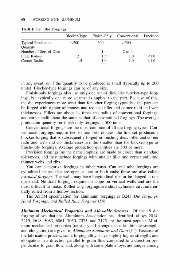
68 WORKING WITH ALUMINUM
TABLE 3.8 Die Forgings
Blocker-Type Finish-Only Conventional Precision
Typical Production �200 500 �500QuantityNumber of Sets of Dies 1 1 2 to 4Fillet Radius 2 1.5 1.0 �1.0Corner Radius 1.5 1.0 1.0 �1.0
in any event, or if the quantity to be produced is small (typically up to 200units). Blocker-type forgings can be of any size.
Finish-only forgings also use only one set of dies, like blocker-type forg-ings, but typically one more squeeze is applied to the part. Because of this,the die experiences more wear than for other forging types, but the part canbe forged with tighter tolerances and reduced fillet and corner radii and webthicknesses. Fillets are about 1 times the radius of conventional forgings,1–2and corner radii about the same as that of conventional forgings. The averageproduction quantity for finish-only forgings is 500 units.
Conventional forgings are the most common of all die forging types. Con-ventional forgings require two to four sets of dies; the first set produces ablocker forging that is subsequently forged in finishing dies. Fillet and cornerradii and web and rib thicknesses are the smaller than for blocker-type orfinish-only forgings. Average production quantities are 500 or more.
Precision forgings, as the name implies, are made to closer than standardtolerances, and they include forgings with smaller fillet and corner radii andthinner webs and ribs.
You can categorize forgings in other ways. Can and tube forgings arecylindrical shapes that are open at one or both ends; these are also calledextruded forgings. The walls may have longitudinal ribs or be flanged at oneopen end. No-draft forgings require no slope on vertical walls and are themost difficult to make. Rolled ring forgings are short cylinders circumferen-tially rolled from a hollow section.
The ASTM specification for aluminum forgings is B247 Die Forgings,Hand Forgings, and Rolled Ring Forgings (54).
Minimum Mechanical Properties and Allowable Stresses Of the 19 dieforging alloys that the Aluminum Association has identified, alloys 2014,2219, 2618, 5083, 6061, 7050, 7075, and 7175 are the most popular. Mini-mum mechanical properties (tensile yield strength, tensile ultimate strength,and elongation) are given in Aluminum Standards and Data (11). Because ofthe fabrication process, some forging alloys have slightly higher strengths andelongation in a direction parallel to grain flow compared to a direction per-pendicular to grain flow, and, along with some plate alloys, are unique among
3.1 PRODUCT FORMS 69
aluminum products in this regard. Forgings produced to the 6061-T6 temper,a good candidate for construction applications, have the same minimumstrengths in both directions, and the same strength as extrusions of this temper.In complex shapes, the grain flow direction may not be obvious, and micro-structural analysis may be needed.
While tensile yield and ultimate strengths are listed in Aluminum Standardsand Data, compressive yield and shear ultimate and yield strengths are not,nor are they given in the Aluminum Specification. If these properties areneeded to perform structural design calculations, you should obtain them fromthe producer.
Quality Assurance for Die Forgings Aluminum Standards and Data re-quires that compliance with minimum mechanical property requirements fordie forgings be demonstrated by testing the following number of samples: (1)for parts weighing up to and including 5 lb [2.5 kg], one sample is taken foreach 2,000 lb [1,000 kg], or part thereof, in a lot; and (2) for parts weighingmore than 5 lb, one sample is taken for each 6,000 lb [3,000 kg], or partthereof, in a lot. Testing is applicable to a direction only when the corre-sponding dimension is more than 2.000 in. [50 mm] thick. ASTM B247requires ultrasonic inspection for discontinuities for certain 2xxx and 7xxxalloys, forging weights, and thicknesses only, so if you want it otherwise youmust specify it. Inspection methods for forgings are the same as for plate, asdiscussed in Section 3.1.2.
Dimensional tolerances are suggested in the Aluminum Forging DesignManual (7). Tolerances for forgings are subject to the same considerations asthose for castings, as discussed in Section 3.1.4.
Identification markings are provided only as required by the forging draw-ing, so call for them there if you want them. As a minimum, it’s a good ideato require identification, including part number, vendor identification, andalloy, and to do so with integrally forged, raised letters on the part.
3.1.4 Castings
Introduction Castings are made by pouring molten metal into a mold. Thisprocess is useful for forming complex three-dimensional shapes, but it sufferssome limitations for structural uses. Most castings have more variation inmechanical properties and less ductility than wrought (that is, worked, suchas forged, extruded, or rolled) aluminum alloys. This is due to defects thatare inherent to the casting process, such as porosity and oxide inclusions, andthe variation in cooling rates within a casting. Casting alloys contain largerproportions of alloying elements than wrought alloys, resulting in a hetero-geneous structure that is generally less ductile than the more homogeneousstructure of wrought alloys. Cast alloys also contain more silicon thanwrought alloys to provide the fluidity necessary to make a casting. On the
70 WORKING WITH ALUMINUM
other hand, with proper inspection and design, castings have been used incritical aerospace parts.
Another point to keep in mind is that for two reasons, castings are rarelyhardened by cold working and so are almost always heat-treated. This isbecause castings are, by definition, already produced in essentially their finalshape and they’re brittle. Where some additional shaping is needed, it’s usu-ally in the form of machining, which doesn’t affect the temper. Consequently,almost all castings are heat-treated and bear the T temper.
Cast Alloy Designation System Cast aluminum alloys and wrought alumi-num alloys have different designation systems. While both systems use fourdigits, most similarities end there. The cast alloy designation system has threedigits, followed by a decimal point, followed by another digit (xxx.x). Thefirst digit indicates the primary alloying element. The second two digits des-ignate the alloy, or in the case of commercially pure aluminum cast alloys,the level of purity. The last digit indicates the product form: 1 or 2 for ingot(depending on impurity levels) and 0 for castings. (So unless you’re a pro-ducer, the only cast designations you’ll be concerned with will end in ‘‘.0.’’)Often, the last digit is dropped (for example, A356-T6); this generally impliesthat you’re talking about a casting and simply didn’t bother to append the‘‘.0.’’ A modification of the original alloy is designated by a letter prefix (A,B, C, etc.) to the alloy number. The series and their primary alloying elementsare:
1xx.x - Commercially Pure Aluminum: These alloys have low strength.An application is cast motor rotors.
2xx.x - Copper: These are the strongest cast alloys and are used for ma-chine tools, aircraft, and engine parts. Alloy 203.0 has the highest strength atelevated temperatures and is suitable for service at 400�F [200�C].
3xx.x - Silicon with Copper and/or Magnesium: The 3xx.x alloys haveexcellent fluidity and strength and are the most widely used aluminum castalloys. Alloy 356.0 and its modifications are very popular and used in manyapplications. High silicon alloys have good wear resistance and are used forautomotive engine blocks and pistons.
4xx.x - Silicon: Silicon provides excellent fluidity as it does for wroughtalloys, so these alloys are well suited to intricate castings, such as typewriterframes, and they have good general corrosion resistance. Alloy A444.0 hasmodest strength but good ductility.
5xx.x - Magnesium: Cast alloys with magnesium have good corrosion re-sistance, especially in marine environments, for example, 514.0; good mach-inability; and have good finishing characteristics. They are more difficult tocast than the 2xx, 3xx, and 4xx series, however.
3.1 PRODUCT FORMS 71
6xx.x - Unused.
7xx.x - Zinc: This series is difficult to cast and so is used where finishingor machinability is important. These alloys have moderate or better strengthsand good general corrosion resistance, but they are not suitable for elevatedtemperatures.
8xx.x - Tin: This series is alloyed with about 6% tin and primarily usedfor bearings, being superior to most other materials for this purpose. Thesealloys are used for large rolling mill bearings and connecting rods and crank-case bearings for diesel engines.
9xx.x - Others: This series is reserved for castings alloyed with elementsother than those used in series 1xx.x through 8.xx.
Before the Aluminum Association’s promulgation of this standard desig-nation system (also called the ANSI system, since the Association is the ANSIregistrar for it), the aluminum industry used other designations. Also, otherorganizations such as the federal government, SAE, the U.S. military, andASTM, assigned still other designations to cast alloys. Even though ASTMfinally gave up in 1974, its designations and others are still used by some, sodon’t be alarmed if you occasionally encounter some strange cast alloy des-ignations. (For example, 535.0 is still sometimes called Almag 35.) A cross-reference to former aluminum industry, federal, ASTM, SAE, and militarydesignations is provided in Standards for Aluminum Sand and PermanentMold Castings (AA-CS-M1-85) (23). ASTM B275, Standard Practice forCodification of Certain Nonferrous Metals and Alloys, Cast and Wrought (55),provides old ASTM designations.
Casting Processes Two kinds of molds are commonly used for castings withconstruction applications, sand and permanent mold. Sand castings are ad-dressed by ASTM B26, Standard Specification for Aluminum-Alloy SandCastings (47), and use sand for the mold, which is usable only once. Thismethod is used for larger castings without intricate shapes and produced insmall quantities. Permanent mold castings (ASTM B108, Standard Specifi-cation for Aluminum-Alloy Permanent Mold Castings (48)) are made by in-troducing molten metal by gravity or low pressure into a mold made of somedurable material, such as iron or steel. Permanent mold castings are moreexpensive but are held to tighter dimensional tolerances than sand castings,and can produce parts with wall thicknesses as little as about 0.09 in. [2 mm].Sand castings as large as 7,000 lb [3,000 kg] and permanent mold castingsas large as 400 lb [180 kg] have been produced in aluminum.
Some casting alloys can be made by only one process (sand or permanentmold), while others can be produced by both methods. Generally, minimummechanical properties for an alloy that is sand cast are less than those of thesame alloy when produced by permanent mold. 356.0 and its higher purityversion A356.0 are by far the most commonly used cast alloys in non-
72 WORKING WITH ALUMINUM
aerospace structural applications. The cost premium for A356.0 is usuallyjustifiable in light of its better properties (strength, ductility, and fluidity)compared to 356.0.
There are a number of other types of castings. Die castings (ASTM B85)are produced by the introduction of molten metal under substantial pressureinto a metal die, producing castings with a high degree of fidelity to the die.Die castings are used for castings produced in large volumes because theycan be produced rapidly within relatively tight dimensional tolerances. In-vestment castings (ASTM B618) are produced by surrounding, or investing,an expendable pattern (usually wax or plastic) with a refractory slurry thatsets at room temperature, after which the pattern is removed by heating andthe resulting cavity is filled with molten metal. ASTM also provides a spec-ification for high-strength aluminum alloy castings (ASTM B686) used inairframe, missile, or other critical applications requiring high strength, duc-tility, and quality.
Dimensional Tolerances Suggested standards for dimensional tolerancesfor castings are given in the Aluminum Association’s publication Standardsfor Aluminum Sand and Permanent Mold Castings. Tolerances are held oncastings only when purchasers specify them with orders. This is unlike thecase for rolled and extruded products, for which standard dimensional toler-ances are held by the mill even when purchasers do not specify them. Thedimensions of castings can be hard to control because of difficulty in pre-dicting shrinkage during solidification and warping due to uneven cooling ofthick and thin regions. Without requirements, castings may be produced withdimensions that deviate more widely than you anticipated.
Minimum Mechanical Properties Minimum mechanical properties for somecast alloys taken from ASTM B26 and B108 are shown in Table 3.9. Unlessshown otherwise in the ASTM specifications and Table 3.9, the values givenare the minimum values for separately cast test bars, not for production cast-ings. Minimum strengths for coupons cut from actual production castingsmust be no less than 75% of the values given in Table 3.9. Elongation valuesof coupons from castings must be no less than 25% of the values in Table3.9; in other words, they may be considerably less than the values in the table.Minimum mechanical properties (tensile ultimate and yield strengths and per-cent elongation in 2 in. [50 mm]) for separately cast test bars of cast alumi-num alloys are also given in Standards for Aluminum Sand and PermanentMold Castings and the Aluminum Design Manual, Part V, Material Properties.All strengths in these tables must be multiplied by 0.75 and all elongationsby 0.25 to obtain values for specimens cut from castings. The ASTM B26and B108 specifications are updated more frequently than the Aluminum As-sociation publications and so may better reflect current industry standards.
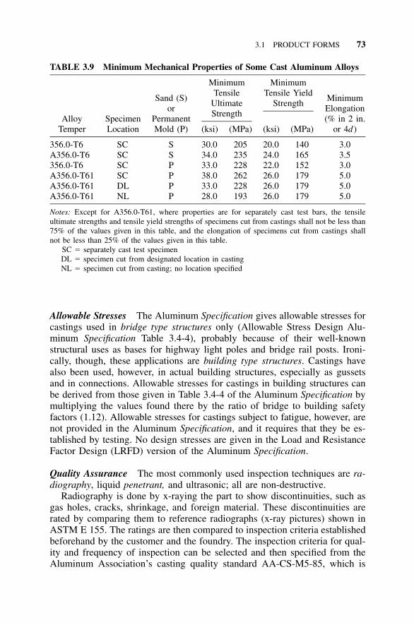
3.1 PRODUCT FORMS 73
TABLE 3.9 Minimum Mechanical Properties of Some Cast Aluminum Alloys
AlloyTemper
SpecimenLocation
Sand (S)or
PermanentMold (P)
MinimumTensile
UltimateStrength
(ksi) (MPa)
MinimumTensile Yield
Strength
(ksi) (MPa)
MinimumElongation(% in 2 in.
or 4d )
356.0-T6 SC S 30.0 205 20.0 140 3.0A356.0-T6 SC S 34.0 235 24.0 165 3.5356.0-T6 SC P 33.0 228 22.0 152 3.0A356.0-T61 SC P 38.0 262 26.0 179 5.0A356.0-T61 DL P 33.0 228 26.0 179 5.0A356.0-T61 NL P 28.0 193 26.0 179 5.0
Notes: Except for A356.0-T61, where properties are for separately cast test bars, the tensileultimate strengths and tensile yield strengths of specimens cut from castings shall not be less than75% of the values given in this table, and the elongation of specimens cut from castings shallnot be less than 25% of the values given in this table.
SC � separately cast test specimenDL � specimen cut from designated location in castingNL � specimen cut from casting; no location specified
Allowable Stresses The Aluminum Specification gives allowable stresses forcastings used in bridge type structures only (Allowable Stress Design Alu-minum Specification Table 3.4-4), probably because of their well-knownstructural uses as bases for highway light poles and bridge rail posts. Ironi-cally, though, these applications are building type structures. Castings havealso been used, however, in actual building structures, especially as gussetsand in connections. Allowable stresses for castings in building structures canbe derived from those given in Table 3.4-4 of the Aluminum Specification bymultiplying the values found there by the ratio of bridge to building safetyfactors (1.12). Allowable stresses for castings subject to fatigue, however, arenot provided in the Aluminum Specification, and it requires that they be es-tablished by testing. No design stresses are given in the Load and ResistanceFactor Design (LRFD) version of the Aluminum Specification.
Quality Assurance The most commonly used inspection techniques are ra-diography, liquid penetrant, and ultrasonic; all are non-destructive.
Radiography is done by x-raying the part to show discontinuities, such asgas holes, cracks, shrinkage, and foreign material. These discontinuities arerated by comparing them to reference radiographs (x-ray pictures) shown inASTM E 155. The ratings are then compared to inspection criteria establishedbeforehand by the customer and the foundry. The inspection criteria for qual-ity and frequency of inspection can be selected and then specified from theAluminum Association’s casting quality standard AA-CS-M5-85, which is
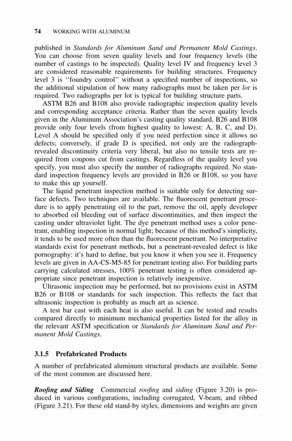
74 WORKING WITH ALUMINUM
published in Standards for Aluminum Sand and Permanent Mold Castings.You can choose from seven quality levels and four frequency levels (thenumber of castings to be inspected). Quality level IV and frequency level 3are considered reasonable requirements for building structures. Frequencylevel 3 is ‘‘foundry control’’ without a specified number of inspections, sothe additional stipulation of how many radiographs must be taken per lot isrequired. Two radiographs per lot is typical for building structure parts.
ASTM B26 and B108 also provide radiographic inspection quality levelsand corresponding acceptance criteria. Rather than the seven quality levelsgiven in the Aluminum Association’s casting quality standard, B26 and B108provide only four levels (from highest quality to lowest: A, B, C, and D).Level A should be specified only if you need perfection since it allows nodefects; conversely, if grade D is specified, not only are the radiograph-revealed discontinuity criteria very liberal, but also no tensile tests are re-quired from coupons cut from castings. Regardless of the quality level youspecify, you must also specify the number of radiographs required. No stan-dard inspection frequency levels are provided in B26 or B108, so you haveto make this up yourself.
The liquid penetrant inspection method is suitable only for detecting sur-face defects. Two techniques are available. The fluorescent penetrant proce-dure is to apply penetrating oil to the part, remove the oil, apply developerto absorbed oil bleeding out of surface discontinuities, and then inspect thecasting under ultraviolet light. The dye penetrant method uses a color pene-trant, enabling inspection in normal light; because of this method’s simplicity,it tends to be used more often than the fluorescent penetrant. No interpretativestandards exist for penetrant methods, but a penetrant-revealed defect is likepornography: it’s hard to define, but you know it when you see it. Frequencylevels are given in AA-CS-M5-85 for penetrant testing also. For building partscarrying calculated stresses, 100% penetrant testing is often considered ap-propriate since penetrant inspection is relatively inexpensive.
Ultrasonic inspection may be performed, but no provisions exist in ASTMB26 or B108 or standards for such inspection. This reflects the fact thatultrasonic inspection is probably as much art as science.
A test bar cast with each heat is also useful. It can be tested and resultscompared directly to minimum mechanical properties listed for the alloy inthe relevant ASTM specification or Standards for Aluminum Sand and Per-manent Mold Castings.
3.1.5 Prefabricated Products
A number of prefabricated aluminum structural products are available. Someof the most common are discussed here.
Roofing and Siding Commercial roofing and siding (Figure 3.20) is pro-duced in various configurations, including corrugated, V-beam, and ribbed(Figure 3.21). For these old stand-by styles, dimensions and weights are given
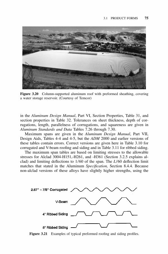
3.1 PRODUCT FORMS 75
Figure 3.20 Column-supported aluminum roof with preformed sheathing, coveringa water storage reservoir. (Courtesy of Temcor)
Figure 3.21 Examples of typical preformed roofing and siding profiles.
in the Aluminum Design Manual, Part VI, Section Properties, Table 31, andsection properties in Table 32. Tolerances on sheet thickness, depth of cor-rugations, length, parallelness of corrugations, and squareness are given inAluminum Standards and Data Tables 7.26 through 7.30.
Maximum spans are given in the Aluminum Design Manual, Part VII,Design Aids, Tables 4-4 and 4-5, but the ADM 2000 and earlier versions ofthese tables contain errors. Correct versions are given here in Table 3.10 forcorrugated and V-beam roofing and siding and in Table 3.11 for ribbed siding.
The maximum span tables are based on limiting stresses to the allowablestresses for Alclad 3004-H151,-H261, and -H361 (Section 3.2.5 explains al-clad) and limiting deflections to 1/60 of the span. The L /60 deflection limitmatches that stated in the Aluminum Specification, Section 8.4.4. Becausenon-alclad versions of these alloys have slightly higher strengths, using the
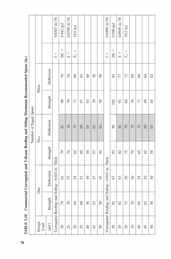
76
TA
BL
E3.
10C
omm
erci
alC
orru
gate
dan
dV
-Bea
mR
oofin
gan
dSi
ding
Max
imum
Rec
omm
ende
dSp
ans
(in.
)
Num
ber
ofE
qual
Span
s
Des
ign
Loa
d
(psf
)
One
Stre
ngth
Defl
ectio
n
Two
Stre
ngth
Defl
ectio
n
Thr
ee
Stre
ngth
Defl
ectio
n
Cor
ruga
ted
Roo
fing
and
Sidi
ng—
0.02
4in
.T
hick
I�
0.03
07in
.4/f
t
2079
6179
8288
76D
L�
0.44
2ps
f
2570
5770
7679
70S
�0.
0708
in.3
/ft
3064
5464
7272
66F
b�
18.6
ksi
3560
5160
6867
63
4056
4956
6563
60
4553
4753
6359
58
5050
4550
6156
56
Cor
ruga
ted
Roo
fing
and
Sidi
ng—
0.03
2in
.T
hick
I�
0.04
09in
.4/f
t
2092
6792
9010
283
DL
�0.
589
psf
2582
6382
8492
77S
�0.
0936
in.3
/ft
3075
5975
7984
73F
b�
19.2
ksi
3570
5670
7578
69
4065
5465
7273
66
4562
5262
6969
64
5058
5058
6765
62
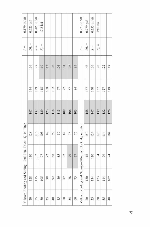
77
V-B
eam
Roo
fing
and
Slid
ing—
0.03
2in
.T
hick
,4
in.
Pitc
h7 – 8
I�
0.17
9in
.4/f
t
2012
811
012
814
714
413
6D
L�
0.62
3ps
f
2511
510
211
513
712
912
7S
�0.
205
in.3
/ft
3010
597
105
129
118
119
Fb
�17
.3ks
i
3598
9298
123
109
113
4092
8892
118
102
108
4586
8586
113
9710
4
5082
8282
109
9210
1
5578
7978
106
8798
6075
7775
103
8495
V-B
eam
Roo
fing
and
Sidi
ng—
0.04
0in
.T
hick
,4
in.
Pitc
h7 – 8
I�
0.22
3in
.4/f
t
2015
011
815
015
816
714
6D
L�
0.77
9ps
f
2513
411
013
414
715
013
6S
�0.
255
in.3
/ft
3012
310
412
313
913
712
8F
b�
19.0
ksi
3511
499
114
132
127
122
4010
794
107
126
119
117
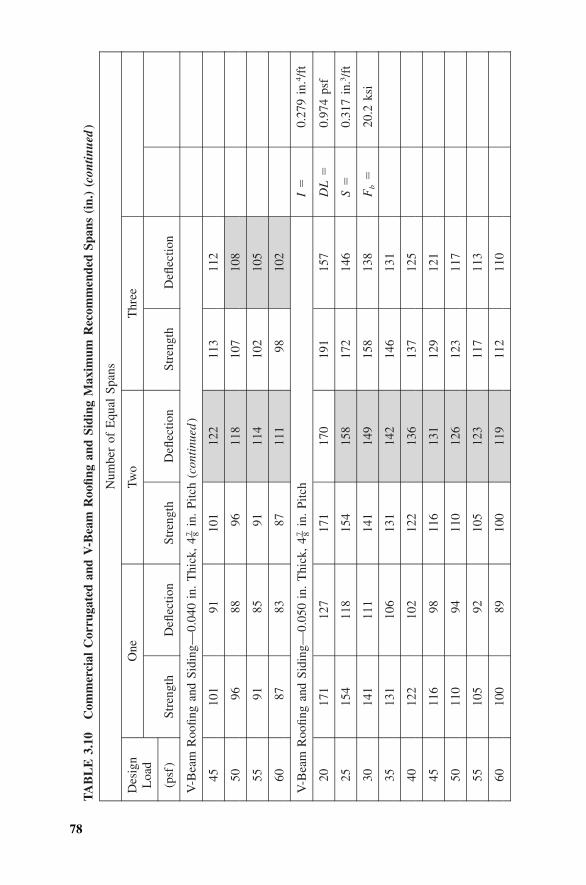
78
TA
BL
E3.
10C
omm
erci
alC
orru
gate
dan
dV
-Bea
mR
oofin
gan
dSi
ding
Max
imum
Rec
omm
ende
dSp
ans
(in.
)(c
ontin
ued
)
Num
ber
ofE
qual
Span
s
Des
ign
Loa
d
(psf
)
One
Stre
ngth
Defl
ectio
n
Two
Stre
ngth
Defl
ectio
n
Thr
ee
Stre
ngth
Defl
ectio
n
V-B
eam
Roo
fing
and
Sidi
ng—
0.04
0in
.T
hick
,4
in.
Pitc
h(c
onti
nued
)7 – 8
4510
191
101
122
113
112
5096
8896
118
107
108
5591
8591
114
102
105
6087
8387
111
9810
2
V-B
eam
Roo
fing
and
Sidi
ng—
0.05
0in
.T
hick
,4
in.
Pitc
h7 – 8
I�
0.27
9in
.4/f
t
2017
112
717
117
019
115
7D
L�
0.97
4ps
f
2515
411
815
415
817
214
6S
�0.
317
in.3
/ft
3014
111
114
114
915
813
8F
b�
20.2
ksi
3513
110
613
114
214
613
1
4012
210
212
213
613
712
5
4511
698
116
131
129
121
5011
094
110
126
123
117
5510
592
105
123
117
113
6010
089
100
119
112
110
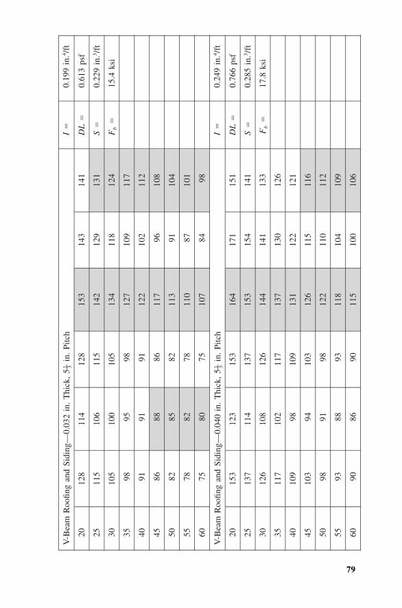
79
V-B
eam
Roo
fing
and
Sidi
ng—
0.03
2in
.T
hick
,5
in.
Pitc
h1 – 3
I�
0.19
9in
.4/f
t
2012
811
412
815
314
314
1D
L�
0.61
3ps
f
2511
510
611
514
212
913
1S
�0.
229
in.3
/ft
3010
510
010
513
411
812
4F
b�
15.4
ksi
3598
9598
127
109
117
4091
9191
122
102
112
4586
8886
117
9610
8
5082
8582
113
9110
4
5578
8278
110
8710
1
6075
8075
107
8498
V-B
eam
Roo
fing
and
Sidi
ng—
0.04
0in
.T
hick
,5
in.
Pitc
h1 – 3
I�
0.24
9in
.4/f
t
2015
312
315
316
417
115
1D
L�
0.76
6ps
f
2513
711
413
715
315
414
1S
�0.
285
in.3
/ft
3012
610
812
614
414
113
3F
b�
17.8
ksi
3511
710
211
713
713
012
6
4010
998
109
131
122
121
4510
394
103
126
115
116
5098
9198
122
110
112
5593
8893
118
104
109
6090
8690
115
100
106
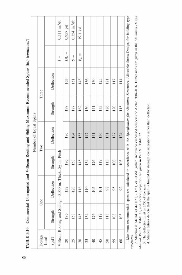
80
TA
BL
E3.
10C
omm
erci
alC
orru
gate
dan
dV
-Bea
mR
oofin
gan
dSi
ding
Max
imum
Rec
omm
ende
dSp
ans
(in.
)(c
ontin
ued
)
Num
ber
ofE
qual
Span
s
Des
ign
Loa
d
(psf
)
One
Stre
ngth
Defl
ectio
n
Two
Stre
ngth
Defl
ectio
n
Thr
ee
Stre
ngth
Defl
ectio
n
V-B
eam
Roo
fing
and
Sidi
ng—
0.05
0in
.T
hick
,5
in.
Pitc
h1 – 3
I�
0.31
1in
.4/f
t
2017
613
217
617
619
716
3D
L�
0.95
7ps
f
2515
812
315
816
417
715
1S
�0.
354
in.3
/ft
3014
511
614
515
516
214
3F
b�
19.1
ksi
3513
411
013
414
715
013
6
4012
610
512
614
114
113
0
4511
910
111
913
613
312
5
5011
398
113
131
126
121
5510
895
108
127
120
117
6010
392
103
124
115
114
1.M
axim
umre
com
men
ded
span
sar
eca
lcul
ated
inac
cord
ance
with
the
Spec
ifica
tion
for
Alu
min
umSt
ruct
ures
,A
llow
able
Stre
ssD
esig
n,fo
rbu
ildin
gty
pest
ruct
ures
.2.
Mat
eria
lis
Alc
lad
3004
-H15
1,-H
261,
or-H
361
(whi
char
est
ucco
embo
ssed
tem
pers
)or
Alc
lad
3004
-H16
.D
imen
sion
sar
egi
ven
inth
eA
lum
inum
Des
ign
Man
ual,
Part
VI,
Tabl
e31
,an
dse
ctio
npr
oper
ties
are
give
nin
Part
VI,
Tabl
e32
.3.
The
defle
ctio
nlim
itis
1/60
ofth
esp
an.
4.Sh
aded
entr
ies
deno
teth
atth
esp
anis
limite
dby
stre
ngth
cons
ider
atio
nsra
ther
than
defle
ctio
n.
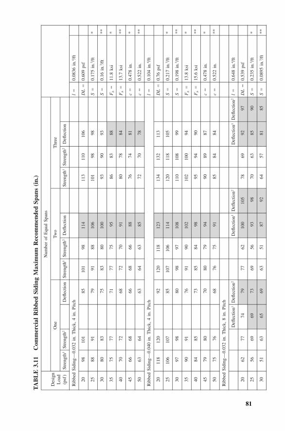
81
TA
BL
E3.
11C
omm
erci
alR
ibbe
dSi
ding
Max
imum
Rec
omm
ende
dSp
ans
(in.
)
Des
ign
Loa
d(p
sf)
Num
ber
ofE
qual
Span
s
One
Stre
ngth
1St
reng
th2
Defl
ectio
n
Two
Stre
ngth
1St
reng
th2
Defl
ectio
n
Thr
ee
Stre
ngth
1St
reng
th2
Defl
ectio
n
Rib
bed
Sidi
ng—
0.03
2in
.T
hick
,4
in.
Pitc
hl
�0.
0836
in.4
/ft
2098
101
8510
198
114
113
110
106
DL
�0.
609
psf
2588
9179
9188
106
101
9898
S�
0.17
5in
.3/f
t*
3080
8375
8380
100
9390
93S
�0.
16in
.3/f
t**
3575
7771
7775
9586
8388
Fb
�11
.8ks
i*
4070
7268
7270
9180
7884
Fb
�13
.7ks
i**
4566
6866
6866
8876
7481
c�
0.47
8in
.*
5063
6463
6463
8572
7078
c�
0.52
2in
.**
Rib
bed
Sidi
ng—
0.04
0in
.T
hick
,4
in.
Pitc
hl
�0.
104
in.4
/ft
2011
812
092
120
118
123
134
132
113
DL
�0.
76ps
f
2510
610
785
107
106
114
120
118
105
S�
0.21
7in
.3/f
t*
3097
9880
9897
108
110
108
99S
�0.
198
in.3
/ft
**
3590
9176
9190
102
102
100
94F
b�
13.8
ksi
*
4084
8573
8584
9895
9490
Fb
�15
.6ks
i**
4579
8070
8079
9490
8987
c�
0.47
8in
.*
5075
7668
7675
9185
8484
c�
0.52
2in
.**
Rib
bed
Sidi
ng—
0.03
2in
.T
hick
,8
in.
Pitc
h
Defl
ectio
n1D
eflec
tion2
Defl
ectio
n1D
eflec
tion2
Defl
ectio
n1D
eflec
tion2
l�
0.64
8in
.4/f
t
2062
7774
7977
6210
010
578
6992
97D
L�
0.53
9ps
f
2556
6969
7369
5693
9870
6385
90S
�0.
235
in.3
/ft
*
3051
6365
6963
5187
9264
5781
85S
�0.
0895
in.3
/ft
**
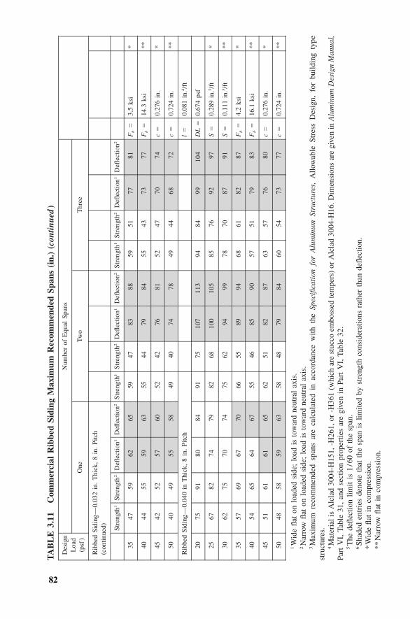
82
TA
BL
E3.
11C
omm
erci
alR
ibbe
dSi
ding
Max
imum
Rec
omm
ende
dSp
ans
(in.
)(c
ontin
ued
)
Des
ign
Loa
d(p
sf)
Num
ber
ofE
qual
Span
s
One
Two
Thr
ee
Rib
bed
Sidi
ng—
0.03
2in
.T
hick
,8
in.
Pitc
h(c
ontin
ued) St
reng
th1
Stre
ngth
2D
eflec
tion1
Defl
ectio
n2St
reng
th1
Stre
ngth
2D
eflec
tion1
Defl
ectio
n2St
reng
th1
Stre
ngth
2D
eflec
tion1
Defl
ectio
n2
3547
5962
6559
4783
8859
5177
81F
b�
3.5
ksi
*
4044
5559
6355
4479
8455
4373
77F
b�
14.3
ksi
**
4542
5257
6052
4276
8152
4770
74c
�0.
276
in.
*
5040
4955
5849
4074
7849
4468
72c
�0.
724
in.
**
Rib
bed
Sidi
ng—
0.04
0in
Thi
ck,
8in
.Pi
tch
l�
0.08
1in
.4/f
t
2075
9180
8491
7510
711
394
8499
104
DL
�0.
674
psf
2567
8274
7982
6810
010
585
7692
97S
�0.
289
in.3
/ft
*
3062
7570
7475
6294
9978
7087
91S
�0.
111
in.3
/ft
**
3557
6967
7066
5589
9468
6182
87F
b�
4.2
ksi
*
4054
6564
6755
4685
9057
5179
83F
b�
16.1
ksi
**
4551
6161
6562
5182
8763
5776
80c
�0.
276
in.
*
5048
5859
6358
4879
8460
5473
77c
�0.
724
in.
**
1W
ide
flat
onlo
aded
side
;lo
adis
tow
ard
neut
ral
axis
.2N
arro
wfla
ton
load
edsi
de;
load
isto
war
dne
utra
lax
is.
3M
axim
umre
com
men
ded
span
sar
eca
lcul
ated
inac
cord
ance
with
the
Spec
ifica
tion
for
Alu
min
umSt
ruct
ures
,A
llow
able
Stre
ssD
esig
n,fo
rbu
ildin
gty
pest
ruct
ures
.4M
ater
ial
isA
lcla
d30
04-H
151,
-H26
1,or
-H36
1(w
hich
are
stuc
coem
boss
edte
mpe
rs)
orA
lcla
d30
04-H
16.D
imen
sion
sar
egi
ven
inA
lum
inum
Des
ign
Man
ual,
Part
VI,
Tabl
e31
,an
dse
ctio
npr
oper
ties
are
give
nin
Part
VI,
Tabl
e32
.5T
hede
flect
ion
limit
is1
/60
ofth
esp
an.
6Sh
aded
entr
ies
deno
teth
atth
esp
anis
limite
dby
stre
ngth
cons
ider
atio
nsra
ther
than
defle
ctio
n.*
Wid
efla
tin
com
pres
sion
.**
Nar
row
flat
inco
mpr
essi
on.
3.1 PRODUCT FORMS 83
maximum span tables is conservative for non-alclad versions of these alloys.The Aluminum Design Manual, Part VIII, Illustrative Example 29 shows howsection moduli, load carrying capacity, and deflections are calculated for 8 in.ribbed siding. Ribbed roofing is not addressed in the Manual. Ribbed sidingis not symmetric about its neutral axis, so its ability to span depends on howit’s oriented with respect to the direction of the load.
Standard finishes available for roofing and siding as purchased from themanufacturer are given in Aluminum Standards and Data, Table 7.20. Theseinclude mill finish, stucco embossed, painted, and low reflectance. Stuccoembossed sheet is an economical way to reduce the effect on appearance ofsmudges and other surface marring. Chances are the manufacturer of yourrefrigerator used this trick. The low reflectance finish is measured in accord-ance with ASTM Method D 523. More information on finishes is given inSection 3.2.
Roofing and siding can be produced in almost any length because they aremade from coil. However, shipping considerations and allowance for thermalexpansion may limit length. Thermal expansion and contraction is discussedfurther in Section 10.1, Cold-Formed Construction.
Some manufacturers produce corrugated, V-beam, and ribbed sheet inthicknesses not given in the Aluminum Association publications. Other stylesthat various manufacturers produce include standing seam types and thosewith attachment fasteners that are concealed from view. Dimensions for pro-prietary styles should be obtained from the manufacturer; allowable spansmay be provided by the manufacturer or calculated using the method fromExample 29. Obtaining load capacities from manufacturers is easier said thandone. A practical guide is: If the manufacturer doesn’t readily provide theinformation necessary to check load capacity (i.e., section modulus per unitwidth), the section probably doesn’t carry enough load to bother calculatingit. Many standing seam sections fall into this category because they are in-tended to be used with a continuous substrate providing support. Some arecapable of spanning a worthwhile distance between purlins, though. A methodfor calculating the bending deflection of a cold-formed sheet member is givenin Section 10.1.
Tread Plate Tread plate, which is also called checkered plate, diamondplate, and floor plate, has a raised diamond pattern providing a slip-resistantsurface on one side. The ASTM specification is B632, Aluminum-Alloy RolledTread Plate (69). A load-span table is given in the Aluminum Design Manual,Part VII, Design Aids, Table 4-3. This table is based on 6061-T6 plate withsimply supported edges and a limiting deflection of L /150, (where L is theshorter of the two dimensions spanned by the plate) for tread plate thicknessesof 0.188 in., 0.25 in., 0.375 in., and 0.5 in. [5 mm, 6 mm, 10 mm, 12 mm].(Tread plate is also available in 0.100 in., 0.125 in., 0.156 in., and 0.625 in.[2.5 mm, 3.2 mm, 4 mm, 8 mm, and 16 mm thicknesses]). Tread plate iscommonly sold in 48 in. [1,220 mm] widths; 60 in. [1,520 mm] and even 72
84 WORKING WITH ALUMINUM
in. [1,830 mm] widths are available in certain thicknesses. Tolerances for treadplate dimensions (thickness, width, length, height of pattern, camber of pat-tern line, lateral bow, and squareness) are given in Aluminum Standards andData, Tables 7.37 through 7.43. Load-span tables for other support conditions,thicknesses, and spans can be calculated from cases given in Roark’s For-mulas for Stress and Strain, Table 26 (140).
The most common alloy for tread plate is 6061, but it is also produced in3003-H231 with a bright finish and 5086-H34 mill finish.
Punches for holes in tread plate should enter the material from the raisedpattern side.
Bar Grating Aluminum grating is sometimes used as a substitute for plate.It is available in a number of configurations, such as rectangular bar and I-beam bar grating, with various strengths. The grating may be either serratedfor skid-resistance or plain (smooth) and is usually made of 6061-T6, 6063-T5, or 6063-T6. Information, including dimensions and load-carrying capac-ity, is available from manufacturers and the National Association of Archi-tectural Metal Manufacturers (NAAMM).
Corrugated Pipe Two types of corrugated aluminum pipe are available:Factory-made corrugated aluminum pipe made of alclad 3004-H34 sheet
is used for storm-water drainage and culverts. ASTM B745, Corrugated Alu-minum Pipe for Sewers and Drains (72), addresses corrugated pipe, which isavailable in two cross-sectional shapes: Type I, which is circular, and TypeII, which is circular on top and approximately flat on bottom and called pipe-arch. Both shapes are also available with an inner liner of smooth (uncorru-gated) sheet. Circular cross sections are also available with perforations (ofseveral styles) to permit water to flow in or out. Two types of seams are used:helical lock seams, which are mechanically staked (indented) and rivetedseams. The nominal sheet thicknesses range from 0.036 in. [0.91 mm] to0.164 in. [4.17 mm], and circular pipes’ nominal inside diameters range from4 in. [100 mm] to 120 in. [3,000 mm]. Installation practices are given inASTM B788, Installing Factory-Made Corrugated Aluminum Culverts andStorm Sewer Pipe (74); structural design practices are given in ASTM B790,Structural Design of Corrugated Aluminum Pipe, Pipe Arches, and Archesfor Culverts, Storm Sewers, and Other Buried Conduits (76).
Corrugated aluminum structural plate pipe (ASTM B746, Corrugated Alu-minum Alloy Structural Plate for Field-Bolted Pipe, Pipe-Arches, and Arches(73) is suitable for more structurally demanding applications. It’s available incircular and pipe-arch shapes and made with 5052-H141 sheet and plate and6061-T6 or 6063-T6 extruded stiffeners. Seams are bolted and stiffening ribsare used; corrugations are 9 in. � 2.5 in. [230 mm � 64 mm]. Nominalthicknesses range from 0.100 in. [2.54 mm] to 0.250 in. [6.35 mm] in 0.025in. [0.64 mm] increments. Nominal diameters for pipe range from 60 in.[1,525 mm] to 312 in. [7,925 mm]. Installation practices are given in ASTM
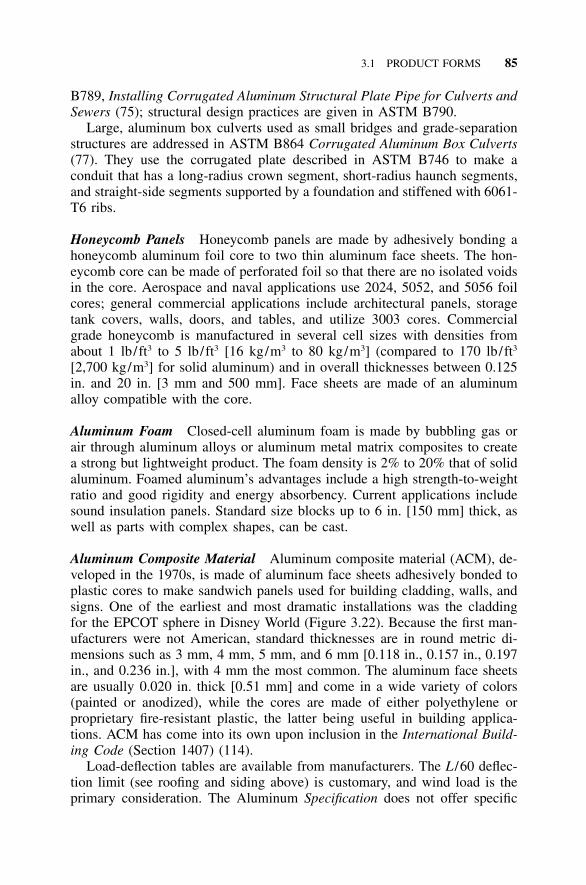
3.1 PRODUCT FORMS 85
B789, Installing Corrugated Aluminum Structural Plate Pipe for Culverts andSewers (75); structural design practices are given in ASTM B790.
Large, aluminum box culverts used as small bridges and grade-separationstructures are addressed in ASTM B864 Corrugated Aluminum Box Culverts(77). They use the corrugated plate described in ASTM B746 to make aconduit that has a long-radius crown segment, short-radius haunch segments,and straight-side segments supported by a foundation and stiffened with 6061-T6 ribs.
Honeycomb Panels Honeycomb panels are made by adhesively bonding ahoneycomb aluminum foil core to two thin aluminum face sheets. The hon-eycomb core can be made of perforated foil so that there are no isolated voidsin the core. Aerospace and naval applications use 2024, 5052, and 5056 foilcores; general commercial applications include architectural panels, storagetank covers, walls, doors, and tables, and utilize 3003 cores. Commercialgrade honeycomb is manufactured in several cell sizes with densities fromabout 1 lb/ft3 to 5 lb/ft3 [16 kg/m3 to 80 kg/m3] (compared to 170 lb/ft3
[2,700 kg/m3] for solid aluminum) and in overall thicknesses between 0.125in. and 20 in. [3 mm and 500 mm]. Face sheets are made of an aluminumalloy compatible with the core.
Aluminum Foam Closed-cell aluminum foam is made by bubbling gas orair through aluminum alloys or aluminum metal matrix composites to createa strong but lightweight product. The foam density is 2% to 20% that of solidaluminum. Foamed aluminum’s advantages include a high strength-to-weightratio and good rigidity and energy absorbency. Current applications includesound insulation panels. Standard size blocks up to 6 in. [150 mm] thick, aswell as parts with complex shapes, can be cast.
Aluminum Composite Material Aluminum composite material (ACM), de-veloped in the 1970s, is made of aluminum face sheets adhesively bonded toplastic cores to make sandwich panels used for building cladding, walls, andsigns. One of the earliest and most dramatic installations was the claddingfor the EPCOT sphere in Disney World (Figure 3.22). Because the first man-ufacturers were not American, standard thicknesses are in round metric di-mensions such as 3 mm, 4 mm, 5 mm, and 6 mm [0.118 in., 0.157 in., 0.197in., and 0.236 in.], with 4 mm the most common. The aluminum face sheetsare usually 0.020 in. thick [0.51 mm] and come in a wide variety of colors(painted or anodized), while the cores are made of either polyethylene orproprietary fire-resistant plastic, the latter being useful in building applica-tions. ACM has come into its own upon inclusion in the International Build-ing Code (Section 1407) (114).
Load-deflection tables are available from manufacturers. The L /60 deflec-tion limit (see roofing and siding above) is customary, and wind load is theprimary consideration. The Aluminum Specification does not offer specific
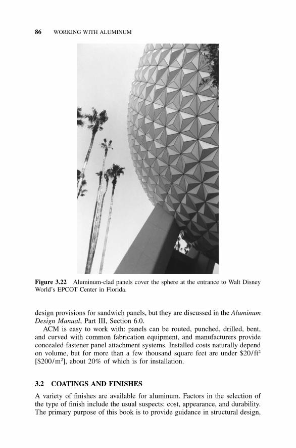
86 WORKING WITH ALUMINUM
Figure 3.22 Aluminum-clad panels cover the sphere at the entrance to Walt DisneyWorld’s EPCOT Center in Florida.
design provisions for sandwich panels, but they are discussed in the AluminumDesign Manual, Part III, Section 6.0.
ACM is easy to work with: panels can be routed, punched, drilled, bent,and curved with common fabrication equipment, and manufacturers provideconcealed fastener panel attachment systems. Installed costs naturally dependon volume, but for more than a few thousand square feet are under $20/ft2
[$200/m2], about 20% of which is for installation.
3.2 COATINGS AND FINISHES
A variety of finishes are available for aluminum. Factors in the selection ofthe type of finish include the usual suspects: cost, appearance, and durability.The primary purpose of this book is to provide guidance in structural design,
3.2 COATINGS AND FINISHES 87
but sometimes design engineers inherit the challenge of specifying a finish,so we’ll give you a little orientation.
Common finishes include mill finish (generally, a fancy way to say ‘‘barealuminum’’), anodizing, painting, and mechanical finishes. Some considera-tions in their use are discussed in this section.
An identification system for aluminum finishes is given in the AluminumAssociation publication Designation System for Aluminum Finishes (14). Thissystem identifies the finish by its mechanical, chemical, and coating charac-teristics, and examples of its use are given below.
3.2.1 Mill Finish
The Aluminum Association publication Specifications for Aluminum SheetMetal Work in Building Construction (21) states:
‘‘One of aluminum’s most useful characteristics is its tendency to develop anextremely thin, tough, invisible oxide coating on its surface immediately onexposure to air. This oxide film, although only 2 to 4 ten-millionths of an inchthick on first forming, is almost completely impermeable and highly resistant toattack by corroding atmospheres.’’
This aluminum-oxide film does not weather away or stain adjacent materials.Whereas most steel must be coated for protection, aluminum is generallycoated only when a certain appearance is desired. When aluminum is left inits natural state, its initial bright appearance will weather through shades ofgray.
When a coating is desired, aluminum may be anodized or painted. Coat-ings, however, may impose a maintenance concern that would not be presentwith mill-finish aluminum since coatings must be maintained. Coatings alsoaffect the price and delivery schedule of aluminum components. Anodizingis limited to pieces that will fit in anodizing tanks and cannot be done in thefield. Tank sizes vary by anodizer, with lengths up to 30 ft [10 m] common-place. Few tanks, however, are deeper than 8 ft [2.5 m], so anodizing limitsshop-assembly sizes. Painting of aluminum is also typically performed in thefactory to take advantage of controlled conditions. This limits the size of anassembly to that which fits in paint booths and ovens. Simply using aluminumin the unadorned state in which it leaves the mill (i.e., mill finish) eliminatesthese limitations on assembly sizes.
Mill finish may be specified under the Aluminum Association system bythe designation ‘‘Mill finish AA-M10 as fabricated.’’
3.2.2 Anodized Finishes
Anodizing is a process that accelerates the formation of the oxide coating onthe surface of aluminum, producing a thicker oxide layer than would occurnaturally. An anodized coating is actually part of the metal, and so has ex-cellent durability. One of the primary advantages of anodizing is its resistance
88 WORKING WITH ALUMINUM
to abrasion. The color, however, depends on the alloying elements and, thus,varies among different alloys and even among parts of the same alloy due tononuniform mixing of alloying elements.
Anodized color tends to be more consistent in some alloys than others.When aluminum is to be anodized, the color match between components ofvarying alloys and fabrications should be considered, but it may result in atrade-off with other considerations, such as price, strength, and corrosion re-sistance. Alloy 3003 is often used for wide sheet, for example, but alloy 5005AQ (anodizing-quality) may be substituted (at a premium price) for improvedcolor consistency. Extrusions of alloys 6463 and 6063 are generally regardedas providing better anodized appearance than 6061, but they are not as strong.When their use is not constrained by price, strength, or availability, 5005sheet material and 6063 extrusion alloy are preferred for color consistency.6463 is used when a bright anodized finish is desired.
Architectural coatings are sometimes specified to tone down the glare frommill finish, as well as to minimize the appearance of handling marks, surfaceimperfections, and minor scratches. A dull gray initial appearance may becost effectively achieved with a Class II clear anodizing of 3003 alloy, fol-lowing an appropriate chemical etch (e.g., C22 medium matte). Over timeClass II clear anodizing might weather unevenly, but it will retain variationsof a dull gray, low-sheen appearance.
Anodizing can also affect at least one structural issue: the selection of weldfiller alloy. As mentioned above, when anodized by the same process, differ-ent alloys will anodize to different colors. Because filler alloys are typicallydifferent than the alloy of the base metal, filler alloys should be selected forgood color match if weldments are to be anodized. An example is weldmentsof 6061, for which the Aluminum Specification (Table 7.2-1) recommend theuse of 4043 filler alloy. However, 4043 anodizes much darker than 6061,resulting in the welds being a distinctly different color than the rest of theanodized assembly. To avoid this two-tone appearance, 5356 filler alloyshould be used. Since anodizing must be removed before welding, assembliesrequiring both welding and anodizing should be welded before anodizing.The size of the completed assembly should, therefore, be limited to that whichwill fit in an anodizing tank.
Specifying an Anodized Finish Designating an anodized finish requires theselection of color, process, and architectural class. The architectural class isan Aluminum Association designation indicating the thickness of the oxidelayer. Class I is the thicker, and more expensive, designation. Some anodizersrecommend Class II as the best value, whereas others believe that Class I willretain a more even appearance over time and is the more suitable choice.Anything thinner than Class II is not recommended for exterior use. Thick-nesses are given in Table 3.12.
Anodizing may be colored or clear. Clear anodizing retains the gray alu-minum color, but it results in a more even appearance than mill finish. The
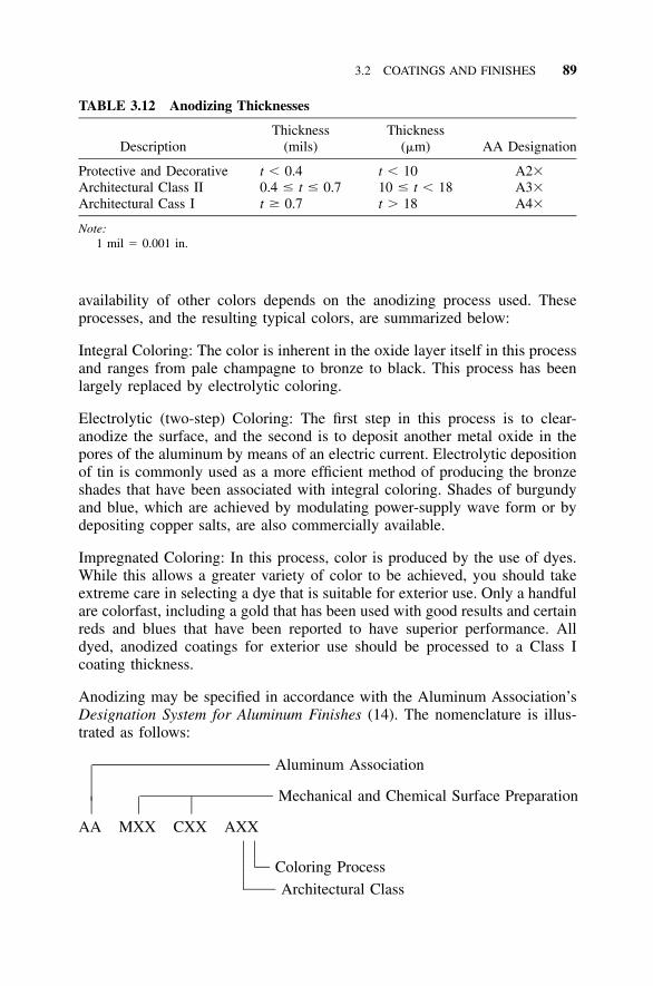
3.2 COATINGS AND FINISHES 89
TABLE 3.12 Anodizing Thicknesses
DescriptionThickness
(mils)Thickness
(�m) AA Designation
Protective and Decorative t � 0.4 t � 10 A2�Architectural Class II 0.4 � t � 0.7 10 � t � 18 A3�Architectural Cass I t � 0.7 t � 18 A4�
Note:1 mil � 0.001 in.
availability of other colors depends on the anodizing process used. Theseprocesses, and the resulting typical colors, are summarized below:
Integral Coloring: The color is inherent in the oxide layer itself in this processand ranges from pale champagne to bronze to black. This process has beenlargely replaced by electrolytic coloring.
Electrolytic (two-step) Coloring: The first step in this process is to clear-anodize the surface, and the second is to deposit another metal oxide in thepores of the aluminum by means of an electric current. Electrolytic depositionof tin is commonly used as a more efficient method of producing the bronzeshades that have been associated with integral coloring. Shades of burgundyand blue, which are achieved by modulating power-supply wave form or bydepositing copper salts, are also commercially available.
Impregnated Coloring: In this process, color is produced by the use of dyes.While this allows a greater variety of color to be achieved, you should takeextreme care in selecting a dye that is suitable for exterior use. Only a handfulare colorfast, including a gold that has been used with good results and certainreds and blues that have been reported to have superior performance. Alldyed, anodized coatings for exterior use should be processed to a Class Icoating thickness.
Anodizing may be specified in accordance with the Aluminum Association’sDesignation System for Aluminum Finishes (14). The nomenclature is illus-trated as follows:
Aluminum Association
Mechanical and Chemical Surface Preparation
AA MXX CXX AXX
Coloring Process
Architectural Class
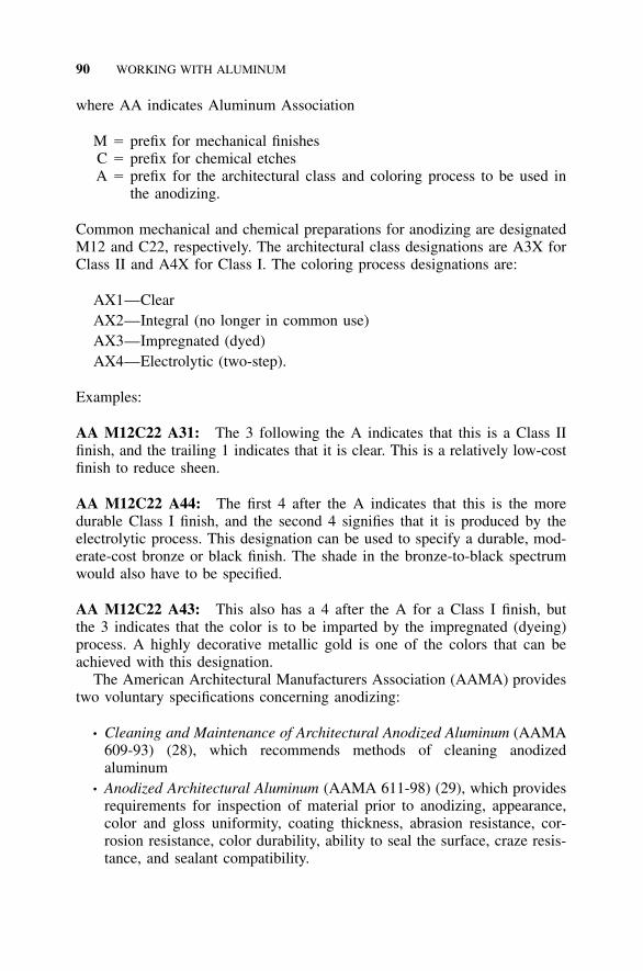
90 WORKING WITH ALUMINUM
where AA indicates Aluminum Association
M � prefix for mechanical finishesC � prefix for chemical etchesA � prefix for the architectural class and coloring process to be used in
the anodizing.
Common mechanical and chemical preparations for anodizing are designatedM12 and C22, respectively. The architectural class designations are A3X forClass II and A4X for Class I. The coloring process designations are:
AX1—ClearAX2—Integral (no longer in common use)AX3—Impregnated (dyed)AX4—Electrolytic (two-step).
Examples:
AA M12C22 A31: The 3 following the A indicates that this is a Class IIfinish, and the trailing 1 indicates that it is clear. This is a relatively low-costfinish to reduce sheen.
AA M12C22 A44: The first 4 after the A indicates that this is the moredurable Class I finish, and the second 4 signifies that it is produced by theelectrolytic process. This designation can be used to specify a durable, mod-erate-cost bronze or black finish. The shade in the bronze-to-black spectrumwould also have to be specified.
AA M12C22 A43: This also has a 4 after the A for a Class I finish, butthe 3 indicates that the color is to be imparted by the impregnated (dyeing)process. A highly decorative metallic gold is one of the colors that can beachieved with this designation.
The American Architectural Manufacturers Association (AAMA) providestwo voluntary specifications concerning anodizing:
• Cleaning and Maintenance of Architectural Anodized Aluminum (AAMA609-93) (28), which recommends methods of cleaning anodizedaluminum
• Anodized Architectural Aluminum (AAMA 611-98) (29), which providesrequirements for inspection of material prior to anodizing, appearance,color and gloss uniformity, coating thickness, abrasion resistance, cor-rosion resistance, color durability, ability to seal the surface, craze resis-tance, and sealant compatibility.
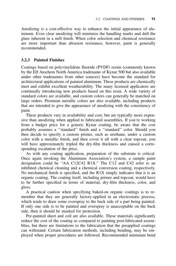
3.2 COATINGS AND FINISHES 91
Anodizing is a cost-effective way to enhance the initial appearance of alu-minum. Even clear anodizing will minimize the handling marks and dull theglare inherent in a mill finish. When color selection and chemical resistanceare more important than abrasion resistance, however, paint is generallyrecommended.
3.2.3 Painted Finishes
Coatings based on polyvinylidene fluoride (PVDF) resins (commonly knownby the Elf Atochem North America tradename of Kynar 500 but also availableunder other tradenames from other sources) have become the standard forarchitectural applications of painted aluminum. These products are chemicallyinert and exhibit excellent weatherability. The many licensed applicators arecontinually introducing new products based on this resin. A wide variety ofstandard colors are available, and custom colors can generally be matched onlarge orders. Premium metallic colors are also available, including productsthat are intended to give the appearance of anodizing with the consistency ofpaint.
These products vary in availability and cost, but are typically more expen-sive than anodizing when applied to fabricated assemblies. If you’re workingfrom a budget price for a generic Kynar coating, be aware that the costprobably assumes a ‘‘standard’’ finish and a ‘‘standard’’ color. Should youthen decide to specify a custom primer, such as urethane, under a customcolor with a metallic finish, and then cover it all with a clear topcoat, youwill have approximately tripled the dry-film thickness and caused a corre-sponding escalation of the price.
As with any coating application, preparation of the substrate is critical.Once again invoking the Aluminum Association’s system, a sample paintdesignation could be ‘‘AA C12C42 R1X.’’ The C12 and C42 refer to aninhibited chemical cleaning and a chemical conversion coating, respectively.No mechanical finish is specified, and the R1X simply indicates that it is anorganic coating. The coating itself, including primer and topcoat, would haveto be further specified in terms of material, dry-film thickness, color, andgloss.
A practical caution when specifying baked-on organic coatings is to re-member that they are generally factory-applied in an electrostatic process,which tends to draw some overspray to the back side of a part being painted.If only one side is to be painted and overspray is unacceptable on the backside, then it should be masked for protection.
Pre-painted sheet and coil are also available. These materials significantlyreduce the cost of the coating as compared to painting post-fabricated assem-blies, but there are limitations to the fabrication that the preapplied coatingscan withstand. Certain fabrication methods, including bending, may be em-ployed when proper procedures are followed. Recommended minimum bend
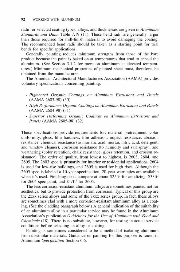
92 WORKING WITH ALUMINUM
radii for selected coating types, alloys, and thicknesses are given in AluminumStandards and Data, Table 7.19 (11). These bend radii are generally largerthan those required for mill-finish material to avoid damaging the coating.The recommended bend radii should be taken as a starting point for trialbends for specific applications.
Generally, painting reduces minimum strengths from those of the bareproduct because the paint is baked on at temperatures that tend to anneal thealuminum. (See Section 3.1.2 for more on aluminum at elevated tempera-tures.) Minimum mechanical properties of painted sheet must, therefore, beobtained from the manufacturer.
The American Architectural Manufacturers Association (AAMA) providesvoluntary specifications concerning painting:
• Pigmented Organic Coatings on Aluminum Extrusions and Panels(AAMA 2603-98) (30)
• High Performance Organic Coatings on Aluminum Extrusions and Panels(AAMA 2604-98) (31)
• Superior Performing Organic Coatings on Aluminum Extrusions andPanels (AAMA 2605-98) (32)
These specifications provide requirements for: material pretreatment, coloruniformity, gloss, film hardness, film adhesion, impact resistance, abrasionresistance, chemical resistance (to muriatic acid, mortar, nitric acid, detergent,and window cleaner), corrosion resistance (to humidity and salt spray), andweathering (color retention, chalk resistance, gloss retention, and erosion re-sistance). The order of quality, from lowest to highest, is 2603, 2604, and2605. The 2603 spec is primarily for interior or residential applications, 2604is used for low-rise buildings, and 2605 is used for high rises. Although the2605 spec is labeled a 10-year-specification, 20-year warranties are availablewhen it’s used. Finishing costs compare at about $2/ft2 for anodizing, $3/ft2
for 2604 spec paint, and $4/ft2 for 2605.The less corrosion-resistant aluminum alloys are sometimes painted not for
aesthetics, but to provide protection from corrosion. Typical of this group arethe 2xxx series alloys and some of the 7xxx series group. In fact, these alloysare sometimes clad with a more corrosion-resistant aluminum alloy as a coat-ing. (See the cladding paragraph below.) A general indication of the suitabilityof an aluminum alloy in a particular service may be found in the AluminumAssociation’s publication Guidelines for the Use of Aluminum with Food andChemicals (18). There is no substitute, however, for testing in actual serviceconditions before selecting an alloy or coating.
Painting is sometimes considered to be a method of isolating aluminumfrom dissimilar materials. Guidance on painting for this purpose is found inAluminum Specification Section 6.6.
3.2 COATINGS AND FINISHES 93
3.2.4 Mechanical Finishes
Mechanical methods, such as abrasion blasting and buffing, may enhance theappearance of aluminum without coatings. These are sometimes called for aseconomical ways to reduce reflectance initially, rather than waiting for naturalweathering to occur. Because abrasion blasting introduces compressive stressto the blasted surface, it tends to curl thin material, and so is limited byAluminum Specification Section 6.7 to material thicker than in. [3 mm]. A1–8floor buffer with a stainless steel pad can be run over flat aluminum sheet toproduce an inexpensive finish and can be used on thinner material.
Both abrasion blasting and buffing have the potential to be performed un-evenly. To achieve a more consistent mechanical finish, run sheet or coilmaterial through a set of textured rollers, thereby producing an embossedfinish. The most common embossed pattern is called stucco, but leather-grainand diamond patterns are also available. These textured patterns tend to hidesmudges, scratches, and other minor surface blemishes. Embossing is readilyavailable on material up to 48 in. [1,220 mm] wide, but finding a facility thatcan handle anything wider is difficult.
3.2.5 Cladding
Some wrought aluminum products (sheet and plate, tube, and wire) may re-ceive a metallurgically bonded coating of high-purity aluminum (such as1230), or corrosion-resistant aluminum alloy, (such as 7008 and 7072), toprovide improved corrosion resistance or certain finish characteristics (likereflectivity), or to facilitate brazing. When such a coating is applied for thispurpose, the product is referred to as alclad (sometimes abbreviated ‘‘alc’’).The thickness of the coating is expressed as a percentage of the total thicknesson a side for sheet and plate, the total wall thickness for tube, and the totalcross-sectional area for wire. Tube is clad on either the inside or the outside,while plate and sheet may be clad on one side or both, but alclad sheet andplate, unless designated otherwise, is clad on both sides. The only tube com-monly clad is of alloy 3003, and the only wire commonly clad is 5056.Among sheet and plate, 2014, 2024, 2219, 3003, 3004, 6061, 7050, 7075,7178, and 7475 are clad. Nominal cladding thicknesses range from 1.5% to10%. More details are given in Aluminum Standards and Data, Table 6.1(11). Alloying elements are often added to the base metal to increase itsstrength, and the cladding typically has lower strength than the base alloybeing clad. This is enough to affect the overall minimum mechanical prop-erties, so alclad material has slightly lower design strengths than non-alcladmaterial of the same alloy and temper. This is accounted for in the minimummechanical properties for alclad sheet; some examples are given in Table 3.13.For all tempers of the 3003 and 3004 alloys, the alclad tensile ultimatestrength is 1 ksi [5 MPa] less than the non-alclad strength.
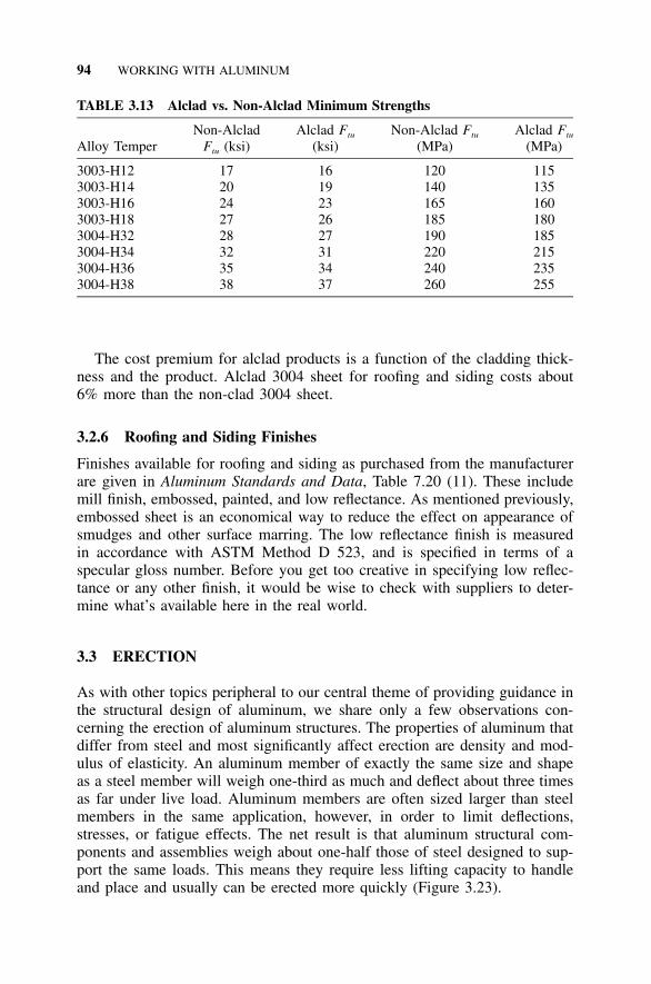
94 WORKING WITH ALUMINUM
TABLE 3.13 Alclad vs. Non-Alclad Minimum Strengths
Alloy TemperNon-Alclad
Ftu (ksi)Alclad Ftu
(ksi)Non-Alclad Ftu
(MPa)Alclad Ftu
(MPa)
3003-H12 17 16 120 1153003-H14 20 19 140 1353003-H16 24 23 165 1603003-H18 27 26 185 1803004-H32 28 27 190 1853004-H34 32 31 220 2153004-H36 35 34 240 2353004-H38 38 37 260 255
The cost premium for alclad products is a function of the cladding thick-ness and the product. Alclad 3004 sheet for roofing and siding costs about6% more than the non-clad 3004 sheet.
3.2.6 Roofing and Siding Finishes
Finishes available for roofing and siding as purchased from the manufacturerare given in Aluminum Standards and Data, Table 7.20 (11). These includemill finish, embossed, painted, and low reflectance. As mentioned previously,embossed sheet is an economical way to reduce the effect on appearance ofsmudges and other surface marring. The low reflectance finish is measuredin accordance with ASTM Method D 523, and is specified in terms of aspecular gloss number. Before you get too creative in specifying low reflec-tance or any other finish, it would be wise to check with suppliers to deter-mine what’s available here in the real world.
3.3 ERECTION
As with other topics peripheral to our central theme of providing guidance inthe structural design of aluminum, we share only a few observations con-cerning the erection of aluminum structures. The properties of aluminum thatdiffer from steel and most significantly affect erection are density and mod-ulus of elasticity. An aluminum member of exactly the same size and shapeas a steel member will weigh one-third as much and deflect about three timesas far under live load. Aluminum members are often sized larger than steelmembers in the same application, however, in order to limit deflections,stresses, or fatigue effects. The net result is that aluminum structural com-ponents and assemblies weigh about one-half those of steel designed to sup-port the same loads. This means they require less lifting capacity to handleand place and usually can be erected more quickly (Figure 3.23).

3.3 ERECTION 95
Figure 3.23 An aluminum dome being set in place with a crane. Aluminum domesas large as 190 ft [58 m] in diameter have been built alongside the structure to becovered, and then set in place in this manner. (Courtesy of Conservatek Industries,Inc.)
Field welding of aluminum should be performed only by companies thatspecialize in this type of construction, such as erectors of welded-aluminumstorage tanks. Even then this work is subject to limitations, including frequentradiographic inspection. The old maxim, ‘‘Cut to fit, paint to match,’’ shouldnever be applied to aluminum. It cannot be cleanly cut with an oxygen-acetylene torch, and even if it could, the application of heat would affect itsstrength. It would be preferable to not have any equipment that can generatetemperatures above 150�F [65�C], such as welding equipment and torches, onsite. (The temptation to try to straighten out that beam they bent while un-loading the truck is just too great for some field crews to resist.) Consequently,most aluminum structures are designed to be field assembled by bolting.
One fastener that can be installed very quickly, even under field conditions,is the lockbolt. This fastener system (see Figure 8.5) requires access to bothsides of the joint and consists of a pin that has ribs and a narrow neck section,as well as a collar that is swaged onto the pin. When the tension force in thepin exceeds the strength of its neck, the neck breaks, resulting in a predictableclamping force between the parts joined. The lockbolt cannot be removedwithout destroying the fastener. This can be readily achieved, if necessary, bysplitting the collar with bolt cutters. The need for involved installation pro-cedures, such as those using torque wrenches or turn-of-the-nut methods, is
96 WORKING WITH ALUMINUM
eliminated, and visual inspection is sufficient. Lockbolts useful in aluminumstructures are available in aluminum alloys and austenitic stainless steel. Theydo, however, require special installation tools, which can be bought or rented.Information on the design of fasteners for aluminum structures is given inSection 8.1.
When aluminum weldments are used, consider inspection after installation,even if the welding was performed in the shop. Shipping and erection stressescan damage weldments of any material, and aluminum is no exception. In-formation on welding and weld inspection can be found in Section 8.2.
Aluminum members and assemblies may be marked in the shop for fieldidentification by stamping, scribing, or marking with paint or ink. Stampingshould not be used on parts subject to fatigue and when used should be placedaway from highly stressed areas. Because the location of marking may bedifficult for the engineer to control, paint or ink marking may be preferred.
Take care storing aluminum on the job site. Aluminum that is allowed tostay wet or in contact with other objects will stain. Once stained, the originalappearance cannot be restored. (See Section 3.1.2 regarding water staining.)No harm is done to the strength or life of the material by surface staining,so it is generally accepted on concealed components. Water staining of ex-posed components, however, can leave the structure ‘‘aesthetically chal-lenged’’ (i.e., quite ugly). If sheet material that is to be used on an exposedsurface is left lying flat, either on the ground or in contact with other sheets,you can expect the owner to develop an attitude. That attitude might be ex-pressed as ‘‘Somebody’s going to pay!’’ On the other hand, this entire scenariocan be avoided by simply storing material properly.
Aluminum should also be protected from splatter from uncured concreteor mortar, as well as muriatic acid used to clean or prepare concrete andmasonry. Once these are allowed to stand on aluminum surfaces, the resultingstains cannot be readily removed.
There is no aluminum equivalent to the AISC’s Code of Standard Practicefor Steel Buildings and Bridges (37), which addresses such erection issues asmethods, conditions, safety, and tolerances. The most frequent question is:which tolerances apply to general aluminum construction? Unless a specificcode, such as ASME B96.1 for welded-aluminum storage tanks (85), applies,the AISC Code of Standard Practice is a good starting point. Some differ-ences apply, however, due to differences in properties of steel and aluminum.For example, thermal expansion and contraction of aluminum is about twicethat of steel, so expect about in. of movement per 100 ft for each 15�F1–4change in an aluminum structure (versus about in. in steel), or 2.4 mm per1–810,000 mm for each 10�C change. Also, don’t expect field tolerances to beany tighter than the cumulative effect of aluminum material and fabricationtolerances.
A final caution: because of to its relatively high scrap value, aluminummay need to be secured against what might be charitably termed ‘‘prematuresalvage.’’
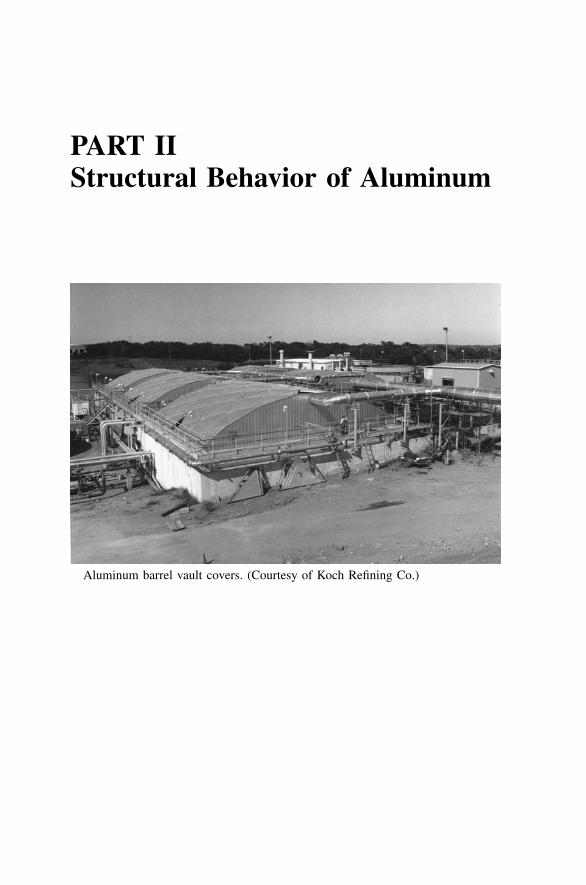
PART IIStructural Behavior of Aluminum
Aluminum barrel vault covers. (Courtesy of Koch Refining Co.)

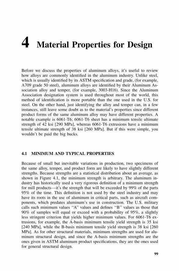
99
4 Material Properties for Design
Before we discuss the properties of aluminum alloys, it’s useful to reviewhow alloys are commonly identified in the aluminum industry. Unlike steel,which is usually identified by its ASTM specification and grade, (for example,A709 grade 50 steel), aluminum alloys are identified by their Aluminum As-sociation alloy and temper, (for example, 3003-H16). Since the AluminumAssociation designation system is used throughout most of the world, thismethod of identification is more portable than the one used in the U.S. forsteel. On the other hand, just identifying the alloy and temper can, in a fewinstances, still leave some doubt as to the material’s properties since differentproduct forms of the same aluminum alloy may have different properties. Anotable example is 6061-T6; 6061-T6 sheet has a minimum tensile ultimatestrength of 42 ksi [290 MPa], whereas 6061-T6 extrusions have a minimumtensile ultimate strength of 38 ksi [260 MPa]. But if this were simple, youwouldn’t be paid the big bucks.
4.1 MINIMUM AND TYPICAL PROPERTIES
Because of small but inevitable variations in production, two specimens ofthe same alloy, temper, and product form are likely to have slightly differentstrengths. Because strengths are a statistical distribution about an average, asshown in Figure 4.1, the minimum strength is arbitrary. The aluminum in-dustry has historically used a very rigorous definition of a minimum strengthfor mill products—it’s the strength that will be exceeded by 99% of the parts95% of the time. This definition is not used by the steel industry and mayhave its roots in the use of aluminum in critical parts, such as aircraft com-ponents, which predates aluminum’s use in construction. The U.S. militarycalls such minimum values ‘‘A’’ values and defines ‘‘B’’ values as those that90% of samples will equal or exceed with a probability of 95%, a slightlyless stringent criterion that yields higher minimum values. For 6061-T6 ex-trusions, for example, the A-basis minimum tensile yield strength is 35 ksi[240 MPa], while the B-basis minimum tensile yield strength is 38 ksi [260MPa]. As for other structural materials, minimum strengths are used for alu-minum structural design, and since the A-basis minimum strengths are theones given in ASTM aluminum product specifications, they are the ones usedfor general structural design.
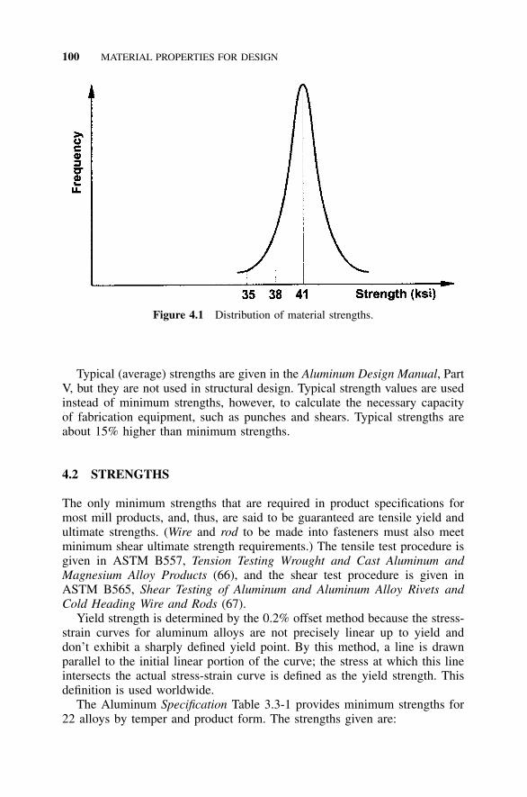
100 MATERIAL PROPERTIES FOR DESIGN
Figure 4.1 Distribution of material strengths.
Typical (average) strengths are given in the Aluminum Design Manual, PartV, but they are not used in structural design. Typical strength values are usedinstead of minimum strengths, however, to calculate the necessary capacityof fabrication equipment, such as punches and shears. Typical strengths areabout 15% higher than minimum strengths.
4.2 STRENGTHS
The only minimum strengths that are required in product specifications formost mill products, and, thus, are said to be guaranteed are tensile yield andultimate strengths. (Wire and rod to be made into fasteners must also meetminimum shear ultimate strength requirements.) The tensile test procedure isgiven in ASTM B557, Tension Testing Wrought and Cast Aluminum andMagnesium Alloy Products (66), and the shear test procedure is given inASTM B565, Shear Testing of Aluminum and Aluminum Alloy Rivets andCold Heading Wire and Rods (67).
Yield strength is determined by the 0.2% offset method because the stress-strain curves for aluminum alloys are not precisely linear up to yield anddon’t exhibit a sharply defined yield point. By this method, a line is drawnparallel to the initial linear portion of the curve; the stress at which this lineintersects the actual stress-strain curve is defined as the yield strength. Thisdefinition is used worldwide.
The Aluminum Specification Table 3.3-1 provides minimum strengths for22 alloys by temper and product form. The strengths given are:
4.3 MODULUS OF ELASTICITY 101
• tensile yield strength (Fty)• tensile ultimate strength (Ftu)• compression yield strength (Fcy)• shear yield strength (Fsy)• shear ultimate strength (Fsu)
The tensile yield and tensile ultimate strengths are the minimum specifiedstrengths from Aluminum Standards and Data (11) (a subset of those in thecorresponding ASTM specifications). Shear ultimate strengths (for materialother than fasteners) and compression yield strengths given in the table arebased on test data since they are not given in product specifications. Theshear yield strengths given were derived by dividing the tensile yield strengthsby (equivalent to multiplying by approximately 0.58 and called the Von�3Mises yield criterion) and rounding the results.
Compressive ultimate strength is not a measured mechanical property foraluminum alloys. For material as ductile as aluminum, compressive ultimatestrength has no meaning; in compressive tests, the metal swells but does notexhibit brittle fracture.
We’ve provided the minimum mechanical properties for the alloys listedin the Aluminum Specification Table 3.3-1, as well as for some additionalalloys, in Appendix C. For other alloys, you must obtain these propertiesfrom the producer, other publications, or approximately derived from theirrelationships with tensile strengths. Approximate relationships between tensileyield and ultimate strengths and other strengths are:
F � 0.9 F For strain-hardened (�H) temperscy ty
F � F For all other temperscy ty
F � 0.6 Fsu tu
F � 0.6 Fsy ty
The strength of thick material tends to be less than for thin material, as shownin Table 4.1 for 5086-H112 plate. The thickness that should be used to de-termine the strength of a product is the original thickness of the material, notthe final fabricated thickness. For example, if a part is machined to a thinnerdimension, the mechanical properties for the original thickness are the properones to be used in structural calculations.
4.3 MODULUS OF ELASTICITY (E), SHEAR MODULUS (G), ANDPOISSON’S RATIO (�)
A material’s modulus of elasticity E (also called Young’s modulus) is the slopeof the elastic portion of the stress-strain curve and is a measure of the ma-
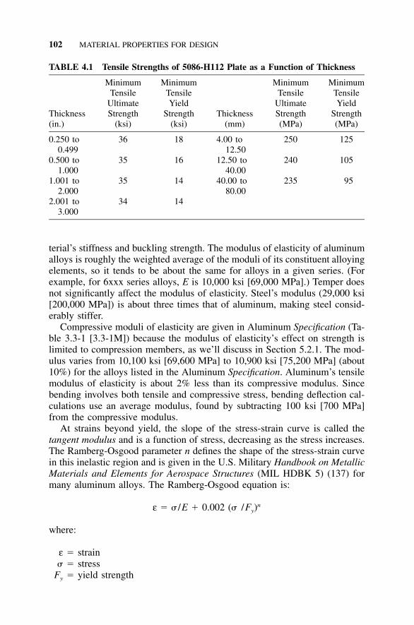
102 MATERIAL PROPERTIES FOR DESIGN
TABLE 4.1 Tensile Strengths of 5086-H112 Plate as a Function of Thickness
Thickness(in.)
MinimumTensile
UltimateStrength
(ksi)
MinimumTensileYield
Strength(ksi)
Thickness(mm)
MinimumTensile
UltimateStrength(MPa)
MinimumTensileYield
Strength(MPa)
0.250 to0.499
36 18 4.00 to12.50
250 125
0.500 to1.000
35 16 12.50 to40.00
240 105
1.001 to2.000
35 14 40.00 to80.00
235 95
2.001 to3.000
34 14
terial’s stiffness and buckling strength. The modulus of elasticity of aluminumalloys is roughly the weighted average of the moduli of its constituent alloyingelements, so it tends to be about the same for alloys in a given series. (Forexample, for 6xxx series alloys, E is 10,000 ksi [69,000 MPa].) Temper doesnot significantly affect the modulus of elasticity. Steel’s modulus (29,000 ksi[200,000 MPa]) is about three times that of aluminum, making steel consid-erably stiffer.
Compressive moduli of elasticity are given in Aluminum Specification (Ta-ble 3.3-1 [3.3-1M]) because the modulus of elasticity’s effect on strength islimited to compression members, as we’ll discuss in Section 5.2.1. The mod-ulus varies from 10,100 ksi [69,600 MPa] to 10,900 ksi [75,200 MPa] (about10%) for the alloys listed in the Aluminum Specification. Aluminum’s tensilemodulus of elasticity is about 2% less than its compressive modulus. Sincebending involves both tensile and compressive stress, bending deflection cal-culations use an average modulus, found by subtracting 100 ksi [700 MPa]from the compressive modulus.
At strains beyond yield, the slope of the stress-strain curve is called thetangent modulus and is a function of stress, decreasing as the stress increases.The Ramberg-Osgood parameter n defines the shape of the stress-strain curvein this inelastic region and is given in the U.S. Military Handbook on MetallicMaterials and Elements for Aerospace Structures (MIL HDBK 5) (137) formany aluminum alloys. The Ramberg-Osgood equation is:
nε � � /E � 0.002 (� /F )y
where:
ε � strain� � stress
Fy � yield strength
4.4 FRACTURE PROPERTIES 103
For example, for 6061-T6 extrusions in longitudinal compression, the typicalRamberg-Osgood parameter n is 38. The parameter varies widely by alloy,temper, product, type of stress, and direction of stress with respect to productdimensions.
The shear modulus of aluminum (also called the modulus of rigidity) isgenerally calculated from its relationship with the modulus of elasticity andPoisson’s ratio (�) for aluminum. Poisson’s ratio (�) is the negative of theratio of transverse strain that accompanies longitudinal strain caused by axialload in the elastic range. Poisson’s ratio is approximately for aluminum1–3alloys, similar to the ratio for steel. While the ratio varies slightly by alloyand decreases slightly as temperature decreases, such variations are insignif-icant for most applications. For a modulus of elasticity of 10,000 ksi [70,000MPa], the shear modulus G is:
1–G � E / [2(1 � �)] � E / [2(1 � )] � 3E /8 � 3,800 ksi [26,000 MPa]3
4.4 FRACTURE PROPERTIES
Ductility is the ability of a material to withstand plastic strain before fracture.Material that is not ductile may fracture at a lower tensile stress than itsminimum ultimate tensile strength because it is unable to deform plasticallyat local stress concentrations that inevitably arise in the real world, even ifthey don’t in machined laboratory-test specimens. Instead, brittle fracture mayoccur at a stress raiser. Since this is premature failure of the part, it’s importantto have a way to measure the ductility of structural alloys. Unfortunately,that’s not so easy.
Fracture toughness is a measure of a material’s resistance to the extensionof a crack. Aluminum has a face-centered cubic crystal structure, so unlikesteel, it does not exhibit a transition temperature below which the materialsuffers a significant loss in fracture toughness. Furthermore, alloys of the1xxx, 3xxx, 4xxx, 5xxx, and 6xxx series are so tough that their fracturetoughness cannot be readily measured by the methods commonly used forless tough materials and is rarely of concern. Alloys of the 2xxx and 7xxxseries are less tough, and when they are used in such fracture critical appli-cations as aircraft, their fracture toughness is of interest to designers. How-ever, the notched bar impact tests that were developed for steel to determinea transition temperature, such as Charpy and Izod tests, don’t work on alu-minum alloys because they don’t have a transition temperature to determine(26).
Instead, the plane-strain fracture toughness (KIc) can be measured byASTM B645 (70). For those products whose fracture toughness cannot bemeasured by this method—such as sheet, which is too thin to apply B645—nonplane-strain fracture toughness (Kc) may be measured by ASTM B646.Fracture toughness is measured in units of ksi [MPa ] and is a�in. �mfunction of thickness (thicker material has lower fracture toughness). Fracture
104 MATERIAL PROPERTIES FOR DESIGN
toughness limits established by the Aluminum Association are given in Alu-minum Standards and Data (11) for certain tempers of several plate and sheetalloys (2124, 7050, and 7475), but none of these alloys are included in theAluminum Specification. Fracture toughness is a function of the orientationof the specimen and the notch relative to the part, so toughness is identifiedby three letters: L for the length direction, T for the width (long transverse)direction, and S for the thickness (short transverse) direction. The first letterdenotes the specimen direction perpendicular to the crack; the second letter,the direction of the notch.
Elongation is defined as the percentage increase in the distance betweentwo gauge marks of a specimen tested to tensile failure. Typical elongationvalues for some aluminum alloys are given in the Aluminum Design Manual,Part V, Table 5. Minimum elongation values for most alloys and product formsare given in Aluminum Standards and Data and ASTM specifications. Theyare dependent on the original gauge length (2 in. [50 mm] is standard forwrought products) and original dimensions, such as thickness, of the speci-men. Elongation values are greater for thicker specimens. For example, typicalelongation values for 1100-O material are 35% for a in. [1.6 mm] thick1––16
specimen, and 45% for a in. [12.5 mm] diameter specimen. Elongation is1–2also very dependent on temperature, being lowest at room temperature andincreasing at both lower and higher temperatures.
The elongation of aluminum alloys tends to be less than mild carbon steels.For example, while A36 steel has a minimum elongation of 20%, the com-parable aluminum alloy, 6061-T6, has a minimum elongation requirement of8% or 10%, depending on the product form. The elongation of annealedtempers is greater than that of strain-hardened or heat-treated tempers, whilethe strength of annealed tempers is less. Therefore, annealed material is moreworkable and has the capacity to undergo more severe forming operationswithout cracking.
All other things being equal, the greater the elongation, the greater theductility. Unfortunately, other things usually aren’t equal for different alloys,so elongation isn’t a very useful indicator of ductility. The percentage reduc-tion in area caused by necking in a tensile specimen tested to failure is similarto elongation in this regard. Unlike elongation, however, the reduction in areais not usually reported for aluminum tensile tests and is not generally availableto designers.
Probably the most accurate measure of ductility (we saved the best for last)is the ratio of the tensile strength of a notched specimen to the tensile yieldstrength, called the notch-yield ratio (119, 120). Various standard notched-specimen specifications are available, but 60� notches with a sharp (0.0005in. [0.01 mm] radius) tip seem to provide good discrimination between var-ious alloys. The notched-specimen strength alone is not very useful sincestress raisers in actual structures aren’t likely to match the test specimen’snotch. But if the notched strength is less than the yield strength of the ma-
4.5 THE EFFECT OF WELDING ON MECHANICAL PROPERTIES 105
terial, then not much yielding can take place before fracture, a condition tobe avoided. Of the alloys in the Aluminum Specification, only 2014-T6 and6070-T6 suffer this fate. Therefore, these alloys (and 6066-T6, which is sim-ilar to 6070-T6) are considered to be notch-sensitive. The effect this has ondesign is discussed in Section 5.1.1.
4.5 THE EFFECT OF WELDING ONMECHANICAL PROPERTIES
Although alloying aluminum with elements like copper or magnesium in-creases the strength of aluminum, much of aluminum alloys’ strength comesfrom precipitation-heat treatments (all tempers beginning with T5, T6, T7,T8, T9, or T10) or strain-hardening (all tempers beginning with H1, H2, H3,or H4). Heating the material tends to erase the effect of precipitation-heattreatments and strain-hardening, so arc welding, which brings a localizedportion of the metal to the melting point, decreases the material’s strength atthe weld. For non-heat-treatable alloys (the ones that are strengthened bystrain-hardening, that is, the 1xxx, 3xxx, and 5xxx series), the heat-affectedzone’s strength is reduced to the annealed strength. For heat-treatable alloys(the 2xxx, 6xxx, and 7xxx series), the heat-affected zone’s strength is reducedto slightly below the solution-heat-treated strength (T4 temper), wiping outthe effect of precipitation-heat treatment. Since the strength of mild carbonsteel is not reduced by welding, welding’s effect on aluminum can be anunpleasant surprise to some structural engineers. Welding does not, however,affect the modulus of elasticity (E) of the metal.
The effect of welding on strength varies by alloy. The reduction in strengthis smallest for some of the 5xxx series alloys designed to be especially suit-able for welding. For example, the unwelded tensile ultimate strength of 5086-H112 plate under 0.500 in. [12.5 mm] thick is 36 ksi [250 MPa]; its weldedstrength is 35 ksi [240 MPa]. At the other extreme, most alloys containingappreciable amounts of copper (these tend to be the highest strength alumi-num alloys and include all of the 2xxx series and many alloys of the 7xxxseries) are difficult to weld at all.
The effect of welding depends on many factors, including how much heatis applied during welding. This can vary by welding process (gas tungsten orgas metal arc welding), thickness of the parts welded, welding speed, andpreheating. It also depends on the filler alloy used. All these effects are av-eraged to establish the minimum welded strengths given in Aluminum Spec-ification Table 3.3-2, and are distinguished from the unwelded strengths byadding w to the subscript. (For example, the minimum welded tensile yieldstrength is Ftyw.) Two warnings should be heeded in using this table:
1) The welded tensile ultimate strengths (Ftuw) must be multiplied by 0.9before they may be used in formulas for member strength in the Specification.
106 MATERIAL PROPERTIES FOR DESIGN
This factor is intended to account for the possibility that welds might receiveonly visual inspection, so their strengths might not be as reliably attained asthat of the AWS qualification welds from which welded tensile ultimatestrengths are established.
2) The welded yield strengths (Ftyw and Fcyw) for tempers other than an-nealed material (�O) must be multiplied by 0.75 before they may be used informulas for member strength in the Specification. This multiplication hasbeen performed, and the results tabulated in Appendix C. This factor effec-tively adjusts the yield strength from a 10 in. [250 mm] to a 2 in. [50 mm]gauge length, which is more representative of weld-affected material. This isbecause the 10 in. gauge length yield strengths were obtained from specimenswith a transverse groove weld that affected only approximately 2 in. [50 mm]of the base metal (1 in. [25 mm] to either side of the weld centerline).
The ultimate tensile strengths for welded aluminum alloys given in Alu-minum Specification Table 3.3-2 are defined there as the AWS D1.2 StructuralWelding Code–Aluminum (91) weld qualification test values. This means thatthese are the strengths that must be attained in a tensile test of a groove weldin order for the weld procedure to be qualified according to AWS require-ments. These same values are also required by the American Society of Me-chanical Engineers (ASME) Boiler and Pressure Vessel Code to qualify aweld procedure. Table 4.2 of AWS D1.2-97 gives values of minimum tensileultimate strength for thicknesses not included in Aluminum Specification Ta-ble 3.3-2, as well as for additional alloys, including several cast alloys.
Section 9.1 explains the structural design of welded members.
4.6 THE EFFECT OF TEMPERATURE ONALUMINUM PROPERTIES
As temperature decreases from room temperature, the tensile strengths andelongation values of aluminum alloys increase, and unlike steel, aluminumsuffers no transition temperature below which the risk of brittle fracture in-creases markedly. This makes aluminum an excellent choice for low-temperature structural applications (2). (This low-temperature ductility is apleasant surprise to engineers familiar with steel.)
On the other hand, aluminum has a considerably lower melting point thansteel (about 1,220�F [660�C]), and the decrease in aluminum strengths is fairlysignificant for most alloys above 200�F [95�C]. Figure 4.2 shows the variationin typical tensile ultimate strength with respect to temperature for variousaluminum alloys. (See Aluminum Design Manual, Part V, for typical tensilestrength and elongation values of alloys at temperatures from �320 to 700�F[�195 to 370�C].) Generally, the longer the alloy is held at an elevated tem-perature, the lower the strength. Under a constant stress, the deformation ofan aluminum part may increase over time; this behavior is known as creep.
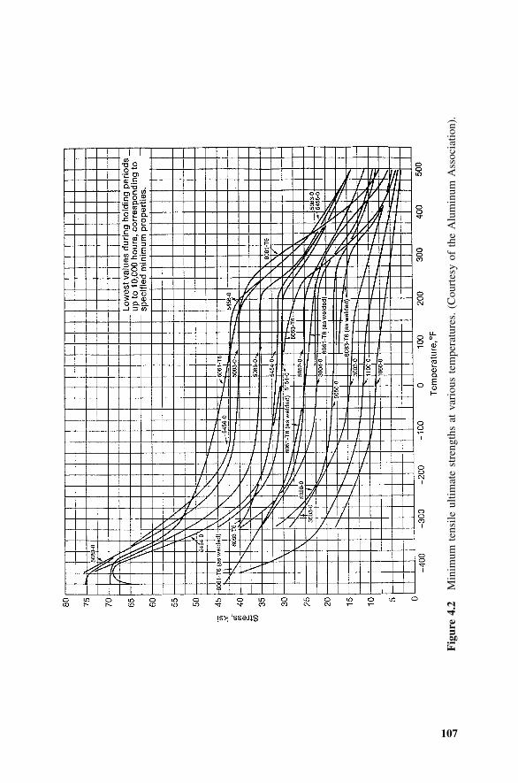
107
Fig
ure
4.2
Min
imum
tens
ileul
timat
est
reng
ths
atva
riou
ste
mpe
ratu
res.
(Cou
rtes
yof
the
Alu
min
umA
ssoc
iatio
n).
108 MATERIAL PROPERTIES FOR DESIGN
Creep effects increase as the temperature increases. At room temperature, verylittle creep occurs unless stresses are near the tensile strength. Creep usuallyis not a factor unless stresses are sustained at temperatures more than about200�F [95�C]. Properties of aluminum alloys at high and low temperaturesare given in Kaufman’s Properties of Aluminum Alloys—Tensile, Creep, andFatigue Data at High and Low Temperatures (118).
For most alloys, the minimum mechanical properties given in the Alumi-num Specification are used for service temperatures up to 200�F [95�C], butabove this are decreased to account for reduced strength. An example of howallowable stresses at elevated temperatures are decreased is given in ASMEB96.1, Welded Aluminum-Alloy Storage Tanks (85). Aluminum alloys are usedin structural applications to 400�F [200�C] with appropriately reduced designstrengths.
Alloys that have more than 3% magnesium content (such as 5083, 5086,5154, and 5456, as well as filler alloys 5183, 5356, 5556, and 5654) shouldnot be held above 150�F [65�C] because these elevated temperatures makethem sensitive to exfoliation corrosion. Exfoliation is a delamination or peel-ing of layers of the metal in planes approximately parallel to the metal sur-face. Unfortunately, magnesium content is directly related to strength, so thisleaves only modest-strength 5xxx alloys available for elevated-temperatureapplications.
4.7 FIRE RESISTANCE
When it comes to fire resistance, aluminum can be confusing (16). On onehand, finely divided aluminum powder burns so explosively that it’s used asrocket fuel; on the other hand, aluminum is routinely melted (every time it’swelded) without any concern regarding combustion. Because of the relativelylow melting point of aluminum alloys (around 1,100�F [600�C]), however,aluminum is not suitable when exposed to high temperatures, such as infireplaces, where it quickly turns to mush. In fires, thin-gauge aluminum sheetcan melt so fast that it appears to be burning. But in reality, semi-fabricatedaluminum products, such as extrusions, sheet, plate, castings, and forgings,are not combustible under ordinary conditions.
Building codes classify a material as noncombustible if it passes ASTME136. In this test, solid pieces of material 1 in. � 1 in. � 2 in. [38 mm �1 1– –2 2
38 mm � 50 mm] are placed in an oven and heated to 1,382�F [750�C];unless flames are produced, the material is called noncombustible. Aluminumalloys subjected to this test have been classified noncombustible since noflames result even though aluminum’s melting point is lower than the testtemperature. Other fire performance tests, such as ASTM E108 for exteriorfire resistance and ASTM E119 for interior fire endurance, exist. These testa building assembly (for example, an insulated metal roofing assembly) andmust be evaluated for specific designs because they are dependent on thedimensions and combination of materials of the assembly being tested.
4.9 PHYSICAL PROPERTIES 109
TABLE 4.2 Typical Hardness Values
Alloy TemperTypical Brinnell Hardness(500 kg load 10 mm ball)
1100-H14 322014-T6 1353003-H16 475005-H34 415052-H32 605454-H32 736061-T6 956063-T5 606063-T6 736101-T6 71
4.8 HARDNESS
The hardness of aluminum alloys isn’t used directly in structural design, butsince it’s relatively easy to measure, it’s frequently reported. Hardness can bemeasured by several methods, including Webster hardness (ASTM B647),Barcol hardness (ASTM B648), Newage hardness (ASTM B724), Vickershardness, and Rockwell hardness (ASTM E18). The Brinnell hardness(ASTM E10) for a 500 kg load on a 10 mm ball is used most often and isgiven in the Aluminum Design Manual, Part V, Table 5 [5M]. Hardness mea-surements are sometimes used for quality-assurance purposes on temper. TheBrinnell hardness number (BHN) multiplied by 0.56 is approximately equalto the ultimate tensile strength (Ftu) in ksi; this relationship can be useful tohelp identify material or estimate its strength based on a simple hardness test.The relationship between hardness and strength, however, is not as dependablefor aluminum as for steel. Hardness measurements are sometimes used tomeasure the effect on strength at various points in the heat-affected zoneacross a weld.
Typical hardness values for some common alloy tempers are given in Table4.2.
4.9 PHYSICAL PROPERTIES
Properties other than mechanical properties are usually referred to under thecatch-all heading of ‘‘physical properties.’’ The significant ones for structuralengineers include density and coefficient of thermal expansion. These prop-erties vary among aluminum alloys; they’re given to three significant figureaccuracy in the Aluminum Design Manual, Part V. Often, however, the vari-ations between alloys aren’t large enough to matter for structural engineeringpurposes.
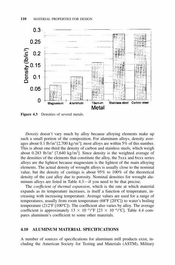
110 MATERIAL PROPERTIES FOR DESIGN
Figure 4.3 Densities of several metals.
Density doesn’t vary much by alloy because alloying elements make upsuch a small portion of the composition. For aluminum alloys, density aver-ages about 0.1 lb/in3 [2,700 kg/m3]; most alloys are within 5% of this number.This is about one-third the density of carbon and stainless steels, which weighabout 0.283 lb/in3 [7,640 kg/m3]. Since density is the weighted average ofthe densities of the elements that constitute the alloy, the 5xxx and 6xxx seriesalloys are the lightest because magnesium is the lightest of the main alloyingelements. The actual density of wrought alloys is usually close to the nominalvalue, but the density of castings is about 95% to 100% of the theoreticaldensity of the cast alloy due to porosity. Nominal densities for wrought alu-minum alloys are listed in Table 4.3—if you need to be that precise.
The coefficient of thermal expansion, which is the rate at which materialexpands as its temperature increases, is itself a function of temperature, in-creasing with increasing temperature. Average values are used for a range oftemperatures, usually from room temperature (68�F [20�C]) to water’s boilingtemperature (212�F [100�C]). The coefficient also varies by alloy. The averagecoefficient is approximately 13 � 10�6 /�F [23 � 10�6 /�C]. Table 4.4 com-pares aluminum’s coefficient to some other materials.
4.10 ALUMINUM MATERIAL SPECIFICATIONS
A number of sources of specifications for aluminum mill products exist, in-cluding the American Society for Testing and Materials (ASTM), Military
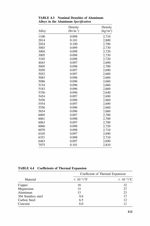
111
TABLE 4.3 Nominal Densities of AluminumAlloys in the Aluminum Specification
AlloyDensity(lb / in.3)
Density(kg/m3)
1100 0.098 2,7102014 0.101 2,8002024 0.100 2,7803003 0.099 2,7303004 0.098 2,7203005 0.098 2,7303105 0.098 2,7204043 0.097 2,6905005 0.098 2,7005050 0.097 2,6905052 0.097 2,6805083 0.096 2,6605086 0.096 2,6605154 0.096 2,6605183 0.096 2,6605356 0.096 2,6405454 0.097 2,6905456 0.096 2,6605554 0.097 2,6905556 0.096 2,6605654 0.096 2,6606005 0.097 2,7006061 0.098 2,7006063 0.097 2,7006066 0.098 2,7206070 0.098 2,7106105 0.097 2,6906351 0.098 2,7106463 0.097 2,6907075 0.101 2,810
TABLE 4.4 Coefficients of Thermal Expansion
Material
Coefficient of Thermal Expansion
� 10�6 / �F � 10�6 / �C
Copper 18 32Magnesium 15 27Aluminum 13 23304 Stainless steel 9.6 17Carbon Steel 6.5 12Concrete 6.0 11
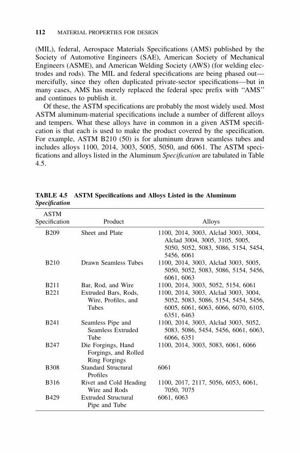
112 MATERIAL PROPERTIES FOR DESIGN
TABLE 4.5 ASTM Specifications and Alloys Listed in the AluminumSpecification
ASTMSpecification Product Alloys
B209 Sheet and Plate 1100, 2014, 3003, Alclad 3003, 3004,Alclad 3004, 3005, 3105, 5005,5050, 5052, 5083, 5086, 5154, 5454,5456, 6061
B210 Drawn Seamless Tubes 1100, 2014, 3003, Alclad 3003, 5005,5050, 5052, 5083, 5086, 5154, 5456,6061, 6063
B211 Bar, Rod, and Wire 1100, 2014, 3003, 5052, 5154, 6061B221 Extruded Bars, Rods,
Wire, Profiles, andTubes
1100, 2014, 3003, Alclad 3003, 3004,5052, 5083, 5086, 5154, 5454, 5456,6005, 6061, 6063, 6066, 6070, 6105,6351, 6463
B241 Seamless Pipe andSeamless ExtrudedTube
1100, 2014, 3003, Alclad 3003, 5052,5083, 5086, 5454, 5456, 6061, 6063,6066, 6351
B247 Die Forgings, HandForgings, and RolledRing Forgings
1100, 2014, 3003, 5083, 6061, 6066
B308 Standard StructuralProfiles
6061
B316 Rivet and Cold HeadingWire and Rods
1100, 2017, 2117, 5056, 6053, 6061,7050, 7075
B429 Extruded StructuralPipe and Tube
6061, 6063
(MIL), federal, Aerospace Materials Specifications (AMS) published by theSociety of Automotive Engineers (SAE), American Society of MechanicalEngineers (ASME), and American Welding Society (AWS) (for welding elec-trodes and rods). The MIL and federal specifications are being phased out—mercifully, since they often duplicated private-sector specifications—but inmany cases, AMS has merely replaced the federal spec prefix with ‘‘AMS’’and continues to publish it.
Of these, the ASTM specifications are probably the most widely used. MostASTM aluminum-material specifications include a number of different alloysand tempers. What these alloys have in common in a given ASTM specifi-cation is that each is used to make the product covered by the specification.For example, ASTM B210 (50) is for aluminum drawn seamless tubes andincludes alloys 1100, 2014, 3003, 5005, 5050, and 6061. The ASTM speci-fications and alloys listed in the Aluminum Specification are tabulated in Table4.5.
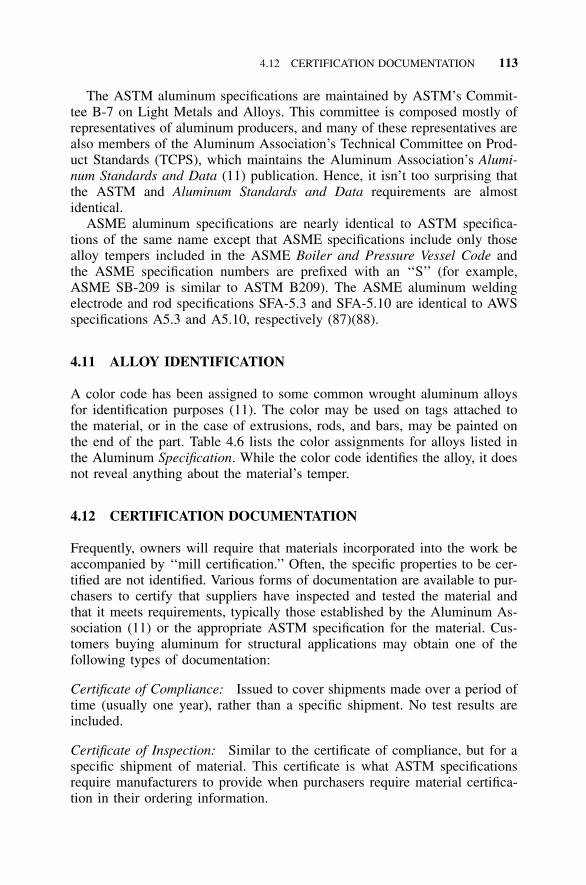
4.12 CERTIFICATION DOCUMENTATION 113
The ASTM aluminum specifications are maintained by ASTM’s Commit-tee B-7 on Light Metals and Alloys. This committee is composed mostly ofrepresentatives of aluminum producers, and many of these representatives arealso members of the Aluminum Association’s Technical Committee on Prod-uct Standards (TCPS), which maintains the Aluminum Association’s Alumi-num Standards and Data (11) publication. Hence, it isn’t too surprising thatthe ASTM and Aluminum Standards and Data requirements are almostidentical.
ASME aluminum specifications are nearly identical to ASTM specifica-tions of the same name except that ASME specifications include only thosealloy tempers included in the ASME Boiler and Pressure Vessel Code andthe ASME specification numbers are prefixed with an ‘‘S’’ (for example,ASME SB-209 is similar to ASTM B209). The ASME aluminum weldingelectrode and rod specifications SFA-5.3 and SFA-5.10 are identical to AWSspecifications A5.3 and A5.10, respectively (87)(88).
4.11 ALLOY IDENTIFICATION
A color code has been assigned to some common wrought aluminum alloysfor identification purposes (11). The color may be used on tags attached tothe material, or in the case of extrusions, rods, and bars, may be painted onthe end of the part. Table 4.6 lists the color assignments for alloys listed inthe Aluminum Specification. While the color code identifies the alloy, it doesnot reveal anything about the material’s temper.
4.12 CERTIFICATION DOCUMENTATION
Frequently, owners will require that materials incorporated into the work beaccompanied by ‘‘mill certification.’’ Often, the specific properties to be cer-tified are not identified. Various forms of documentation are available to pur-chasers to certify that suppliers have inspected and tested the material andthat it meets requirements, typically those established by the Aluminum As-sociation (11) or the appropriate ASTM specification for the material. Cus-tomers buying aluminum for structural applications may obtain one of thefollowing types of documentation:
Certificate of Compliance: Issued to cover shipments made over a period oftime (usually one year), rather than a specific shipment. No test results areincluded.
Certificate of Inspection: Similar to the certificate of compliance, but for aspecific shipment of material. This certificate is what ASTM specificationsrequire manufacturers to provide when purchasers require material certifica-tion in their ordering information.
114 MATERIAL PROPERTIES FOR DESIGN
TABLE 4.6 Color Code for AluminumSpecification Alloys
Alloy Color
1100 White2014 Gray2024 Red3003 Green3004 —3005 —3105 —5005 —5050 —5052 Purple5083 Red and Gray5086 Red and Orange5154 Blue and Green5454 —5456 Gray and Purple6005 —6061 Blue6063 Yellow and Green6066 Red and Green6070 Blue and Gray6105 —6351 Purple and Orange7075 Black
Certificate of Inspection and Test Results: Gives minimum and maximummechanical properties obtained from testing each lot and lists the applicablechemical-composition limits (not the actual chemical-composition).
Certificate of Inspection and Test Results including Chemical Analysis:Gives minimum and maximum mechanical properties and chemical analysisobtained from testing each lot.
These certificates are listed in ascending order of cost. For most routinestructural applications, a certificate of compliance or inspection is usuallysufficient.
115
5 Explanation of theAluminum Specification
This chapter could also have been titled ‘‘Structural Design with Metals’’because it covers a range of metal behavior beyond that covered by the metalspecification we all learned in school (the AISC Specification [38, 39]). In anumber of ways, hot-rolled steel design is just a special case of metal design,while the Aluminum Specification offers a more panoramic view. Ironically,learning about aluminum can actually give you better insight into steel design;in college, most of us studiously avoided any metal but hot-rolled steel.
Design with hot-rolled steel is typically limited to the so-called ‘‘compactsections.’’ These shapes have sufficiently stocky cross-sectional elements solocal buckling is not a concern. In the real world, many metal structures aremade of lighter gauge components instead, whose capacities may be influ-enced by local buckling. We’ll lead you into the land of postbuckling strength,where no compact section has ever gone. If you master this concept, you’llnot only be able to deal with the wide range of shapes available in aluminum,you will also gain some insight into the design of light-gauge steel structures.While the Aluminum Specification addresses the full spectrum of elementslenderness, in steel you have to leave the comfort of the Steel Manual andwade into the complex provisions of the AISI cold-formed steel specification(40) to design members that have very slender elements. Although the Alu-minum Specification and the cold-formed steel specification use entirely dif-ferent methods to address slender elements, they both deal with the samefundamental behavior.
We’ll discuss the Aluminum Specification’s approach to metal design inthis chapter, giving examples and highlighting sections of the Specificationas we cover them. For the plug-and-chug oriented, you can skip to Chapter7, where we’ll keep the discussion to a minimum and provide the step-by-step procedures for applying the Aluminum Specification. Finally, for achecklist of the applicable provisions of the Specification for each mode ofbehavior, refer to Appendix G.
5.1 TENSION MEMBERS
If you’re like most engineers, you appreciate the simplicity of tensile stresses.After all, tensile stresses and strengths are so much easier to calculate than
116 EXPLANATION OF THE ALUMINUM SPECIFICATION
other types of stress. Tensile stresses can cause fracture, however, which is afailure mode that’s sudden and, therefore, usually catastrophic. This is justabout the worst thing that can happen to your structure.
Tensile stresses may also cause yielding, but the consequences are, perhaps,not quite as disastrous as fracture. Some yielding occurs in many structures,whether in a bolt torqued to installation requirements or in a member at astress riser, without robbing the structure of its usefulness. It’s only when theyielding is excessive that failure has occurred.
We’ll keep these limit states in mind as we discuss the Aluminum Speci-fication’s requirements. Identifying the limit of a structure’s usefulness andthen providing an adequate safeguard against reaching that limit are whatdesign specifications are all about.
5.1.1 Tensile Strength
Aluminum Specification Section 3.4.1 effectively defines axial tensile strengthas:
1) Yield strength on the gross area2) Ultimate strength on the net area.
Each of these strengths is factored by its respective safety factor in allow-able stress design. (The strengths are factored by a resistance factor in loadand resistance factor design [LRFD]. We’ll stick to allowable stress designfor now.) The resulting allowable strength of a member is:
F A F Aty g tu nF � min , (5.1)� �t n k ny t u
where:
A � gross area of the memberg
A � net area of the membern
F � tensile yield strengthty
F � tensile ultimate strengthtu
k � coefficient for tension members (see Aluminum Specificationt
Table 3.4-2)n � factor of safety on yieldy
n � factor of safety on ultimate strengthu
This Specification section is highlighted in Aluminum Specification Table 3.4-3 reproduced here as Figure 5.1. The general equations are evaluated forvarious alloys in the Aluminum Design Manual, Part VII, Tables 2-2 through2-23, with 6061-T6 being found on Table 2-21 (reproduced here as Figure5.2).
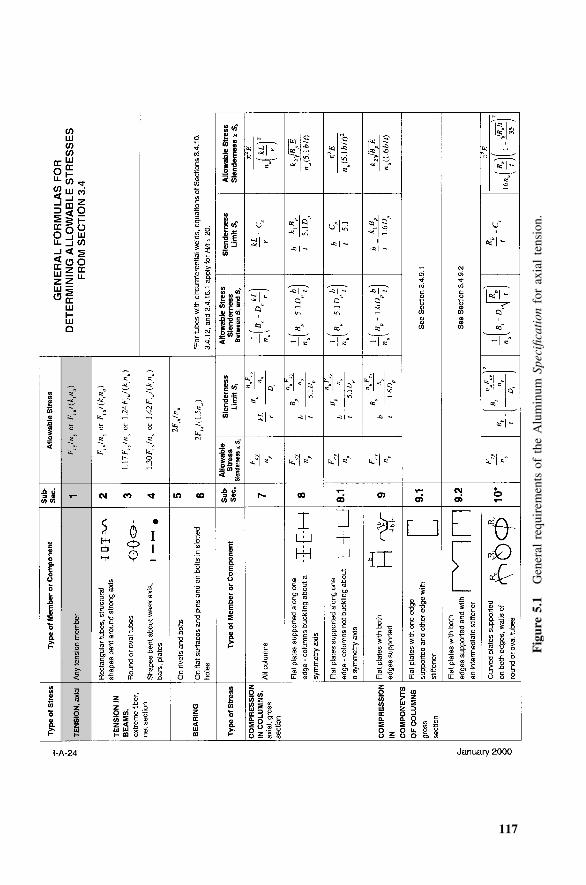
117
Fig
ure
5.1
Gen
eral
requ
irem
ents
ofth
eA
lum
inum
Spec
ifica
tion
for
axia
lte
nsio
n.
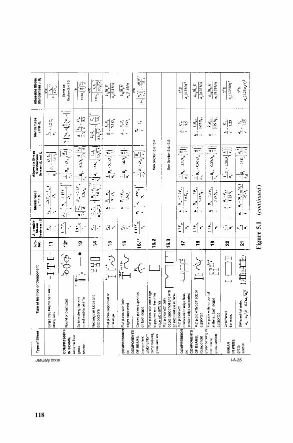
118
Fig
ure
5.1
(con
tinu
ed)
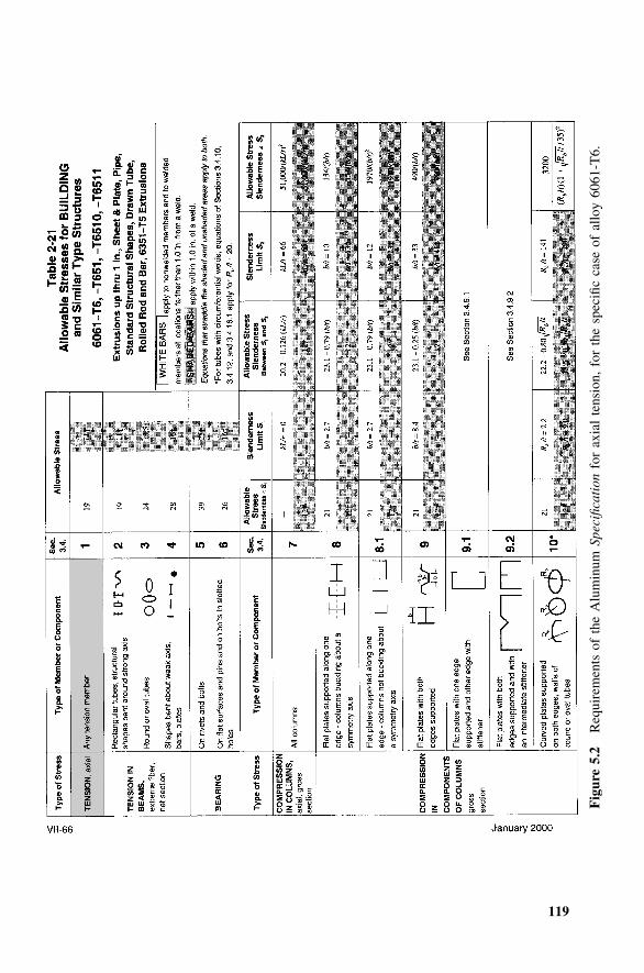
119
Fig
ure
5.2
Req
uire
men
tsof
the
Alu
min
umSp
ecifi
cati
onfo
rax
ial
tens
ion,
for
the
spec
ific
case
ofal
loy
6061
-T6.
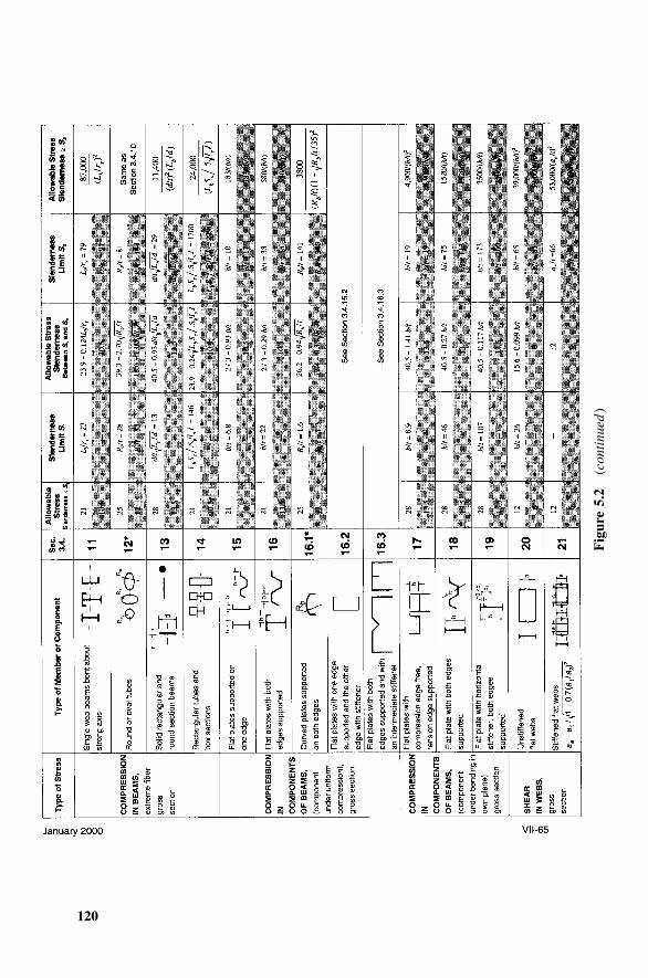
120
Fig
ure
5.2
(con
tinu
ed)
5.1 TENSION MEMBERS 121
Substituting for the factors of safety ny and nu for building structures (fromthe Aluminum Specification Table 3.4-1), the tensile stress checks become:
F A F Aty g tu nF � min , (5.2)� �t 1.65 1.95 kt
Yielding on the net section is not considered a limit state because it’s assumedthat the net section exists over only a small portion of the total length of themember. Therefore, yielding on the net section will result in very little elon-gation of the member in relation to its overall length. Since the gross areausually equals or exceeds the net area and kt is 1 in most cases, fracture willgovern the allowable tensile strength if Fty � 0.85 Ftu. An example is 6061-T6 where Fty /1.65 � (35 ksi) /1.65 � 21.2 ksi and Ftu / [(kt)1.95] � (38 ksi)/[(1.0)(1.95)] � 19.5 ksi. Since the stress on the gross area is always lessthan or equal to the stress on the net area and the allowable stress on thegross area is higher than on the net area, the fracture strength on the net areaalways governs. The Aluminum Design Manual, Part VII, allowable stressdesign aid tables are of limited usefulness because they give only the lesserof the allowable stress based on yield and that based on fracture, even thoughthe stresses these allowable stresses are compared to differ.
The tension coefficient kt is 1.0 for all alloys that appear in the AluminumSpecification except 2014-T6, for which kt is 1.25, and 6066-T6 and 6070-T6, for which it is 1.1. These alloys are notch-sensitive and, thus, require, ineffect, an additional factor of safety against fracture. Notch-sensitive meansthat the ultimate stress on the net section attained in standard tests of speci-mens with sharp notches is less than the specified minimum tensile yieldstrength. For alloys not listed in the Aluminum Specification, users must de-termine the kt factor. (See Section 4.4 of this book for more on this.)
The Aluminum Specification’s provisions for allowable stresses for tensionmembers are actually very similar to those in the Steel Specification. Thesimilarities may be obscured, however, because the aluminum allowablestresses are determined by dividing aluminum strengths by a factor of safety,while the Steel Specification requires multiplying steel strengths by the recip-rocal of the safety factor. The steel allowable tensile strength is:
0.60F (� F /1.67) on the gross area (5.3)ty ty
0.50F (� F /2.00) on the effective net area (5.4)tu tu
The steel safety factors, then, are 1.67 on yield strength (versus 1.65 foraluminum) and 2.0 on ultimate strength (versus 1.95 for aluminum).
At room temperature, not all aluminum alloys exhibit the ability to sustainstresses well above yield, a property some structural designers may take forgranted with A36 steel. This is demonstrated by examining their stress-straincurves up to failure (see Figure 5.3). For example, at a minimum, A36 steel
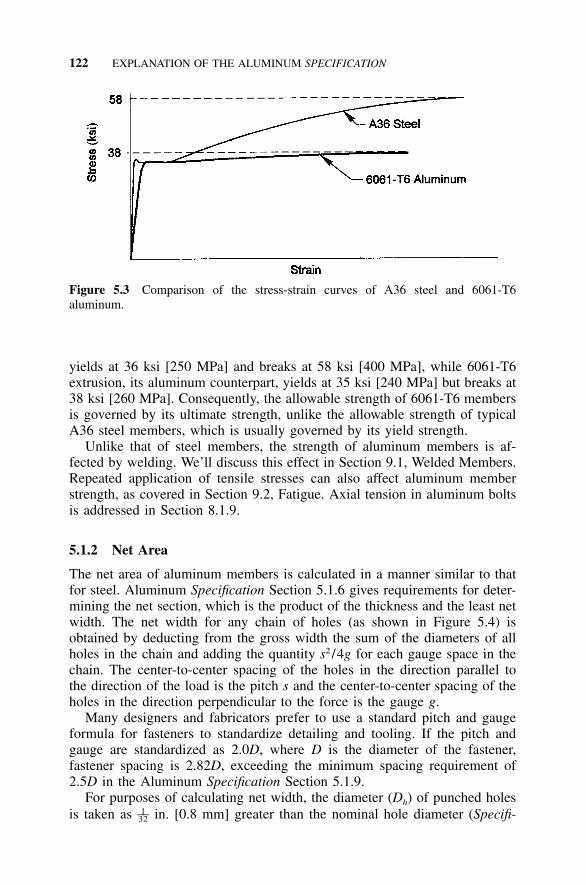
122 EXPLANATION OF THE ALUMINUM SPECIFICATION
Figure 5.3 Comparison of the stress-strain curves of A36 steel and 6061-T6aluminum.
yields at 36 ksi [250 MPa] and breaks at 58 ksi [400 MPa], while 6061-T6extrusion, its aluminum counterpart, yields at 35 ksi [240 MPa] but breaks at38 ksi [260 MPa]. Consequently, the allowable strength of 6061-T6 membersis governed by its ultimate strength, unlike the allowable strength of typicalA36 steel members, which is usually governed by its yield strength.
Unlike that of steel members, the strength of aluminum members is af-fected by welding. We’ll discuss this effect in Section 9.1, Welded Members.Repeated application of tensile stresses can also affect aluminum memberstrength, as covered in Section 9.2, Fatigue. Axial tension in aluminum boltsis addressed in Section 8.1.9.
5.1.2 Net Area
The net area of aluminum members is calculated in a manner similar to thatfor steel. Aluminum Specification Section 5.1.6 gives requirements for deter-mining the net section, which is the product of the thickness and the least netwidth. The net width for any chain of holes (as shown in Figure 5.4) isobtained by deducting from the gross width the sum of the diameters of allholes in the chain and adding the quantity s2 /4g for each gauge space in thechain. The center-to-center spacing of the holes in the direction parallel tothe direction of the load is the pitch s and the center-to-center spacing of theholes in the direction perpendicular to the force is the gauge g.
Many designers and fabricators prefer to use a standard pitch and gaugeformula for fasteners to standardize detailing and tooling. If the pitch andgauge are standardized as 2.0D, where D is the diameter of the fastener,fastener spacing is 2.82D, exceeding the minimum spacing requirement of2.5D in the Aluminum Specification Section 5.1.9.
For purposes of calculating net width, the diameter (Dh) of punched holesis taken as in. [0.8 mm] greater than the nominal hole diameter (Specifi-1––32
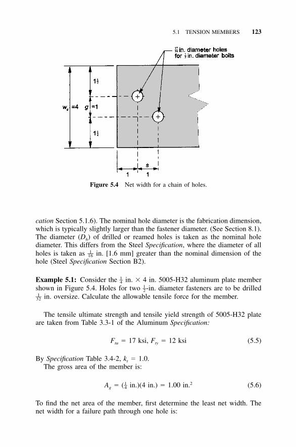
5.1 TENSION MEMBERS 123
+
+
Figure 5.4 Net width for a chain of holes.
cation Section 5.1.6). The nominal hole diameter is the fabrication dimension,which is typically slightly larger than the fastener diameter. (See Section 8.1).The diameter (Dh) of drilled or reamed holes is taken as the nominal holediameter. This differs from the Steel Specification, where the diameter of allholes is taken as in. [1.6 mm] greater than the nominal dimension of the1––16
hole (Steel Specification Section B2).
Example 5.1: Consider the in. � 4 in. 5005-H32 aluminum plate member1–4shown in Figure 5.4. Holes for two -in. diameter fasteners are to be drilled1–2
in. oversize. Calculate the allowable tensile force for the member.1––32
The tensile ultimate strength and tensile yield strength of 5005-H32 plateare taken from Table 3.3-1 of the Aluminum Specification:
F � 17 ksi, F � 12 ksi (5.5)tu ty
By Specification Table 3.4-2, kt � 1.0.The gross area of the member is:
1 2–A � ( in.)(4 in.) � 1.00 in. (5.6)g 4
To find the net area of the member, first determine the least net width. Thenet width for a failure path through one hole is:
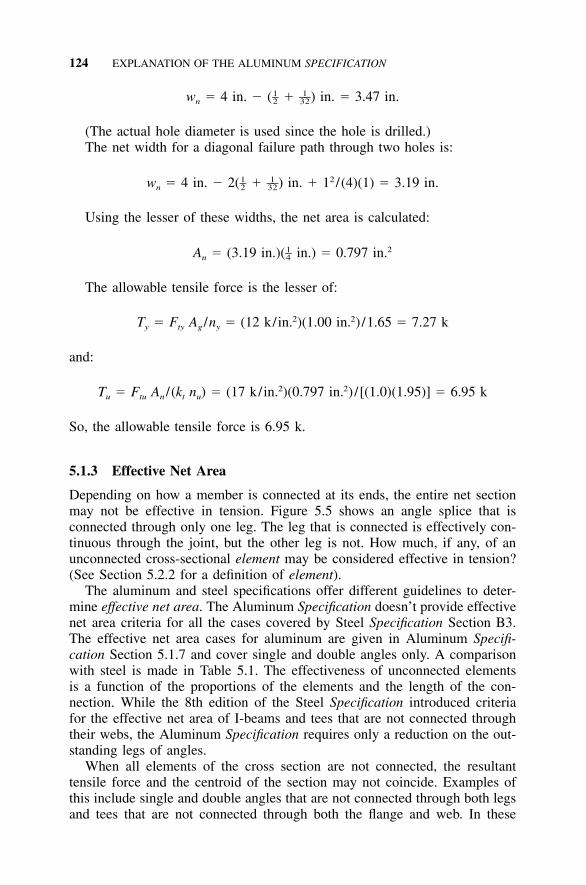
124 EXPLANATION OF THE ALUMINUM SPECIFICATION
1 1– ––w � 4 in. � ( � ) in. � 3.47 in.n 2 32
(The actual hole diameter is used since the hole is drilled.)The net width for a diagonal failure path through two holes is:
1 1 2– ––w � 4 in. � 2( � ) in. � 1 /(4)(1) � 3.19 in.n 2 32
Using the lesser of these widths, the net area is calculated:
1 2–A � (3.19 in.)( in.) � 0.797 in.n 4
The allowable tensile force is the lesser of:
2 2T � F A /n � (12 k/in. )(1.00 in. ) /1.65 � 7.27 ky ty g y
and:
2 2T � F A / (k n ) � (17 k/in. )(0.797 in. ) /[(1.0)(1.95)] � 6.95 ku tu n t u
So, the allowable tensile force is 6.95 k.
5.1.3 Effective Net Area
Depending on how a member is connected at its ends, the entire net sectionmay not be effective in tension. Figure 5.5 shows an angle splice that isconnected through only one leg. The leg that is connected is effectively con-tinuous through the joint, but the other leg is not. How much, if any, of anunconnected cross-sectional element may be considered effective in tension?(See Section 5.2.2 for a definition of element).
The aluminum and steel specifications offer different guidelines to deter-mine effective net area. The Aluminum Specification doesn’t provide effectivenet area criteria for all the cases covered by Steel Specification Section B3.The effective net area cases for aluminum are given in Aluminum Specifi-cation Section 5.1.7 and cover single and double angles only. A comparisonwith steel is made in Table 5.1. The effectiveness of unconnected elementsis a function of the proportions of the elements and the length of the con-nection. While the 8th edition of the Steel Specification introduced criteriafor the effective net area of I-beams and tees that are not connected throughtheir webs, the Aluminum Specification requires only a reduction on the out-standing legs of angles.
When all elements of the cross section are not connected, the resultanttensile force and the centroid of the section may not coincide. Examples ofthis include single and double angles that are not connected through both legsand tees that are not connected through both the flange and web. In these
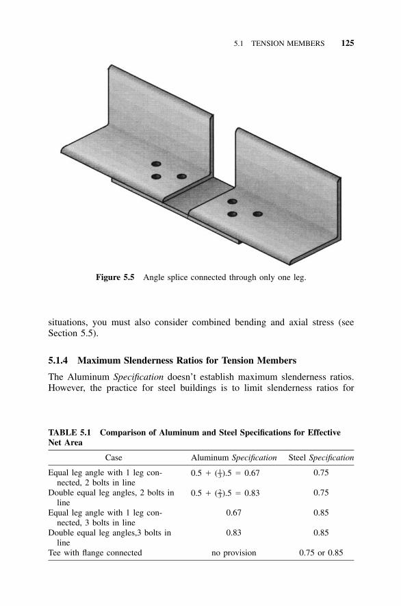
5.1 TENSION MEMBERS 125
Figure 5.5 Angle splice connected through only one leg.
TABLE 5.1 Comparison of Aluminum and Steel Specifications for EffectiveNet Area
Case Aluminum Specification Steel Specification
Equal leg angle with 1 leg con-nected, 2 bolts in line
0.5 � ( ).5 � 0.671–3 0.75
Double equal leg angles, 2 bolts inline
0.5 � ( ).5 � 0.832–3 0.75
Equal leg angle with 1 leg con-nected, 3 bolts in line
0.67 0.85
Double equal leg angles,3 bolts inline
0.83 0.85
Tee with flange connected no provision 0.75 or 0.85
situations, you must also consider combined bending and axial stress (seeSection 5.5).
5.1.4 Maximum Slenderness Ratios for Tension Members
The Aluminum Specification doesn’t establish maximum slenderness ratios.However, the practice for steel buildings is to limit slenderness ratios for

126 EXPLANATION OF THE ALUMINUM SPECIFICATION
tension members to 240 for main members and to 300 for secondary membersor bracing, except rods. This is to limit vibrations and protect against inci-dental loads, such as the weight of workers for which stress calculations maynot be computed. Including such considerations result in a more robust struc-ture; this can be applied to aluminum also. Such a structure is also capableof resisting loads that have the audacity to be slightly different from the loadschosen for structural checks.
5.2 COMPRESSION MEMBERS
In this section, we address members in axial compression. The shorthand termin the Aluminum Specification for such members is columns. This term is notlimited to members actually serving as vertical columns in a building, butrather applies to any member subject to axial compression regardless of itslocation or orientation in a structure.
Wherever compression occurs, buckling lurks as a consideration. Bucklingis strongly influenced by a member’s dimensions, especially cross-sectionalwidths, thicknesses, and configuration. The configuration of aluminum shapesthat can readily be fabricated by such methods as cold-forming and extrudingis almost unlimited, and the Aluminum Specification places no limits on theproportions of members. Consequently, no buckling modes can be dismissedwithout consideration. It’s not that aluminum buckles in ways no self-respecting piece of steel would; any metal produced in the variety of shapesthat aluminum is would require similar buckling checks. This discussion is,thus, an explanation of the buckling behavior of metal columns in general.
First, let’s deal with a matter of terminology. Each structural shape is con-sidered to consist of one or more elements. (In the Aluminum Specification,elements of shapes are also called components of shapes.) Elements are de-fined as plates either rectangular or curved in cross section and connectedonly along their edges to other elements (Figure 5.6). For example, an I-beamconsists of five elements: two rectangular plate elements in each of the twoflanges, and one rectangular plate element called the web. Examples ofshapes, called profiles in the aluminum industry, and their component ele-ments are shown in Figure 5.7. An angle is an example of a shape with onlytwo elements; one element for each leg. Other shapes may be considerablymore complex, but all are treated as assemblies of elements, each of whichare approximated by a rectangular plate or by a curved plate of a single radius.
It is helpful to first list all the ways that buckling can occur in a member,called buckling modes, and then deal with them one at a time. Buckling maybe divided into two types: overall buckling, which occurs over the length ofthe member (the way a yardstick buckles), and local buckling, which is con-fined to an element of a cross section over a length about equal to the widthof the element. Figure 5.8 illustrates an example of overall buckling, which
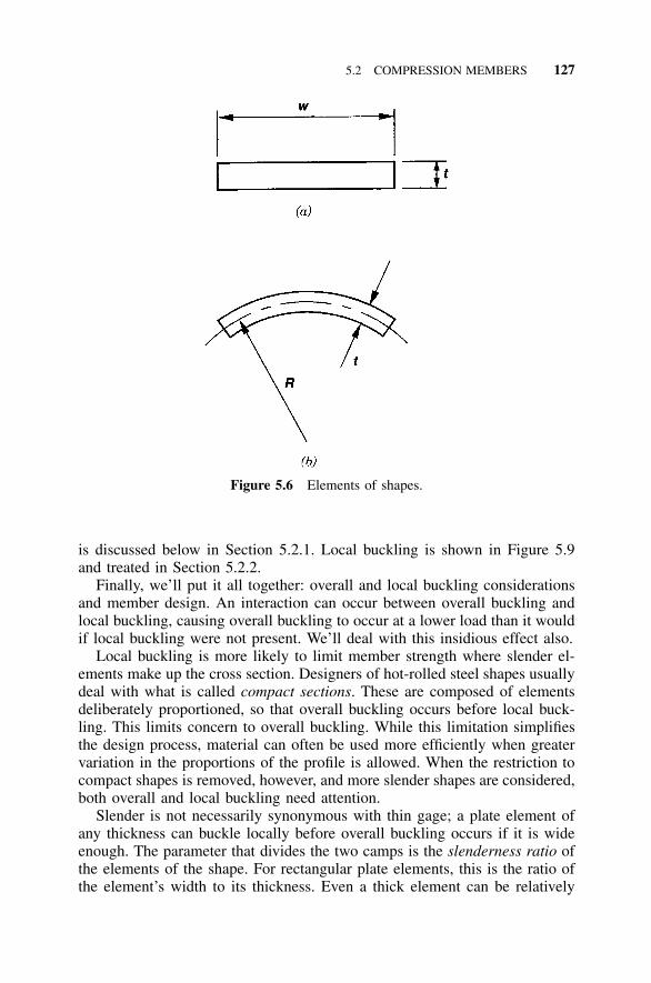
5.2 COMPRESSION MEMBERS 127
Figure 5.6 Elements of shapes.
is discussed below in Section 5.2.1. Local buckling is shown in Figure 5.9and treated in Section 5.2.2.
Finally, we’ll put it all together: overall and local buckling considerationsand member design. An interaction can occur between overall buckling andlocal buckling, causing overall buckling to occur at a lower load than it wouldif local buckling were not present. We’ll deal with this insidious effect also.
Local buckling is more likely to limit member strength where slender el-ements make up the cross section. Designers of hot-rolled steel shapes usuallydeal with what is called compact sections. These are composed of elementsdeliberately proportioned, so that overall buckling occurs before local buck-ling. This limits concern to overall buckling. While this limitation simplifiesthe design process, material can often be used more efficiently when greatervariation in the proportions of the profile is allowed. When the restriction tocompact shapes is removed, however, and more slender shapes are considered,both overall and local buckling need attention.
Slender is not necessarily synonymous with thin gage; a plate element ofany thickness can buckle locally before overall buckling occurs if it is wideenough. The parameter that divides the two camps is the slenderness ratio ofthe elements of the shape. For rectangular plate elements, this is the ratio ofthe element’s width to its thickness. Even a thick element can be relatively
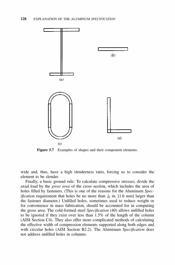
128 EXPLANATION OF THE ALUMINUM SPECIFICATION
Figure 5.7 Examples of shapes and their component elements.
wide and, thus, have a high slenderness ratio, forcing us to consider theelement to be slender.
Finally, a basic ground rule: To calculate compressive stresses, divide theaxial load by the gross area of the cross section, which includes the area ofholes filled by fasteners. (This is one of the reasons for the Aluminum Spec-ification requirement that holes be no more than in. [1.6 mm] larger than1––16
the fastener diameter.) Unfilled holes, sometimes used to reduce weight orfor convenience in mass fabrication, should be accounted for in computingthe gross area. The cold-formed steel Specification (40) allows unfilled holesto be ignored if they exist over less than 1.5% of the length of the column(AISI Section C4). They also offer more complicated methods of calculatingthe effective width of compression elements supported along both edges andwith circular holes (AISI Section B2.2). The Aluminum Specification doesnot address unfilled holes in columns.
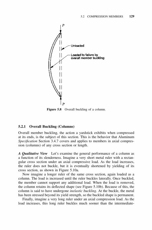
5.2 COMPRESSION MEMBERS 129
Figure 5.8 Overall buckling of a column.
5.2.1 Overall Buckling (Columns)
Overall member buckling, the action a yardstick exhibits when compressedat its ends, is the subject of this section. This is the behavior that AluminumSpecification Section 3.4.7 covers and applies to members in axial compres-sion (columns) of any cross section or length.
A Qualitative View Let’s examine the general performance of a column asa function of its slenderness. Imagine a very short metal ruler with a rectan-gular cross section under an axial compressive load. As the load increases,the ruler does not buckle, but it is eventually shortened by yielding of itscross section, as shown in Figure 5.10a.
Now imagine a longer ruler of the same cross section, again loaded as acolumn. The load is increased until the ruler buckles laterally. Once buckled,the member cannot support any additional load. When the load is removed,the column retains its deflected shape (see Figure 5.10b). Because of this, thecolumn is said to have undergone inelastic buckling. At the buckle, the metalhas been stressed beyond its yield strength, so the buckled shape is permanent.
Finally, imagine a very long ruler under an axial compression load. As theload increases, this long ruler buckles much sooner than the intermediate-
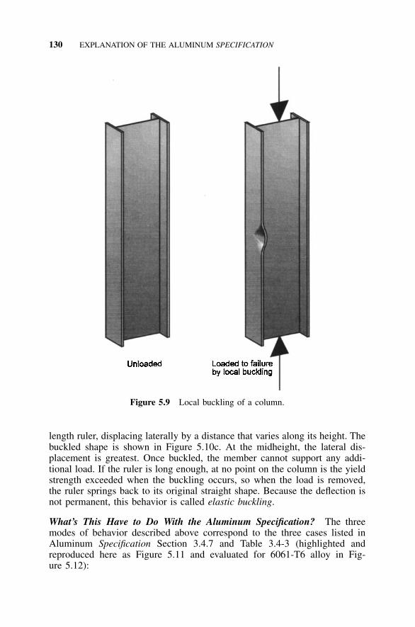
130 EXPLANATION OF THE ALUMINUM SPECIFICATION
Figure 5.9 Local buckling of a column.
length ruler, displacing laterally by a distance that varies along its height. Thebuckled shape is shown in Figure 5.10c. At the midheight, the lateral dis-placement is greatest. Once buckled, the member cannot support any addi-tional load. If the ruler is long enough, at no point on the column is the yieldstrength exceeded when the buckling occurs, so when the load is removed,the ruler springs back to its original straight shape. Because the deflection isnot permanent, this behavior is called elastic buckling.
What’s This Have to Do With the Aluminum Specification? The threemodes of behavior described above correspond to the three cases listed inAluminum Specification Section 3.4.7 and Table 3.4-3 (highlighted andreproduced here as Figure 5.11 and evaluated for 6061-T6 alloy in Fig-ure 5.12):
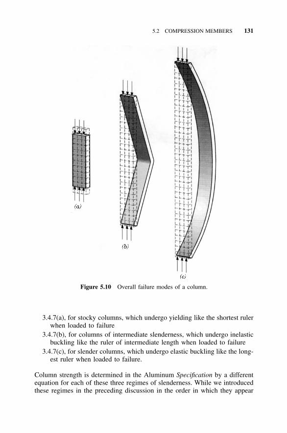
5.2 COMPRESSION MEMBERS 131
Figure 5.10 Overall failure modes of a column.
3.4.7(a), for stocky columns, which undergo yielding like the shortest rulerwhen loaded to failure
3.4.7(b), for columns of intermediate slenderness, which undergo inelasticbuckling like the ruler of intermediate length when loaded to failure
3.4.7(c), for slender columns, which undergo elastic buckling like the long-est ruler when loaded to failure.
Column strength is determined in the Aluminum Specification by a differentequation for each of these three regimes of slenderness. While we introducedthese regimes in the preceding discussion in the order in which they appear
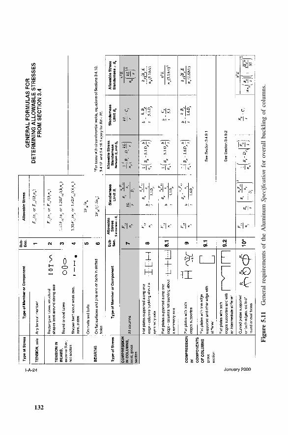
132
Fig
ure
5.11
Gen
eral
requ
irem
ents
ofth
eA
lum
inum
Spec
ifica
tion
for
over
all
buck
ling
ofco
lum
ns.
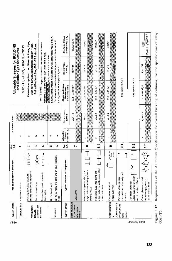
133
Fig
ure
5.12
Req
uire
men
tsof
the
Alu
min
umSp
ecifi
cati
onfo
rov
eral
lbu
cklin
gof
colu
mns
,fo
rth
esp
ecifi
cca
seof
allo
y60
61-T
6.
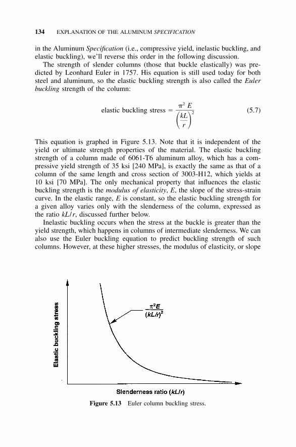
134 EXPLANATION OF THE ALUMINUM SPECIFICATION
Figure 5.13 Euler column buckling stress.
in the Aluminum Specification (i.e., compressive yield, inelastic buckling, andelastic buckling), we’ll reverse this order in the following discussion.
The strength of slender columns (those that buckle elastically) was pre-dicted by Leonhard Euler in 1757. His equation is still used today for bothsteel and aluminum, so the elastic buckling strength is also called the Eulerbuckling strength of the column:
2� Eelastic buckling stress � (5.7)2kL� �r
This equation is graphed in Figure 5.13. Note that it is independent of theyield or ultimate strength properties of the material. The elastic bucklingstrength of a column made of 6061-T6 aluminum alloy, which has a com-pressive yield strength of 35 ksi [240 MPa], is exactly the same as that of acolumn of the same length and cross section of 3003-H12, which yields at10 ksi [70 MPa]. The only mechanical property that influences the elasticbuckling strength is the modulus of elasticity, E, the slope of the stress-straincurve. In the elastic range, E is constant, so the elastic buckling strength fora given alloy varies only with the slenderness of the column, expressed asthe ratio kL /r, discussed further below.
Inelastic buckling occurs when the stress at the buckle is greater than theyield strength, which happens in columns of intermediate slenderness. We canalso use the Euler buckling equation to predict buckling strength of suchcolumns. However, at these higher stresses, the modulus of elasticity, or slope
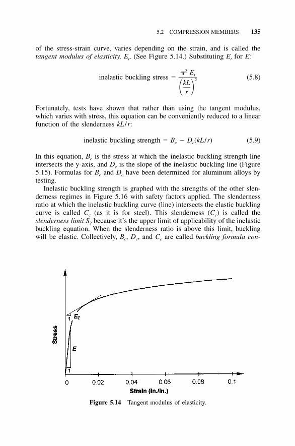
5.2 COMPRESSION MEMBERS 135
Figure 5.14 Tangent modulus of elasticity.
of the stress-strain curve, varies depending on the strain, and is called thetangent modulus of elasticity, Et. (See Figure 5.14.) Substituting Et for E:
2� Etinelastic buckling stress � (5.8)2kL� �r
Fortunately, tests have shown that rather than using the tangent modulus,which varies with stress, this equation can be conveniently reduced to a linearfunction of the slenderness kL /r:
inelastic buckling strength � B � D (kL /r) (5.9)c c
In this equation, Bc is the stress at which the inelastic buckling strength lineintersects the y-axis, and Dc is the slope of the inelastic buckling line (Figure5.15). Formulas for Bc and Dc have been determined for aluminum alloys bytesting.
Inelastic buckling strength is graphed with the strengths of the other slen-derness regimes in Figure 5.16 with safety factors applied. The slendernessratio at which the inelastic buckling curve (line) intersects the elastic bucklingcurve is called Cc (as it is for steel). This slenderness (Cc) is called theslenderness limit S2 because it’s the upper limit of applicability of the inelasticbuckling equation. When the slenderness ratio is above this limit, bucklingwill be elastic. Collectively, Bc, Dc, and Cc are called buckling formula con-
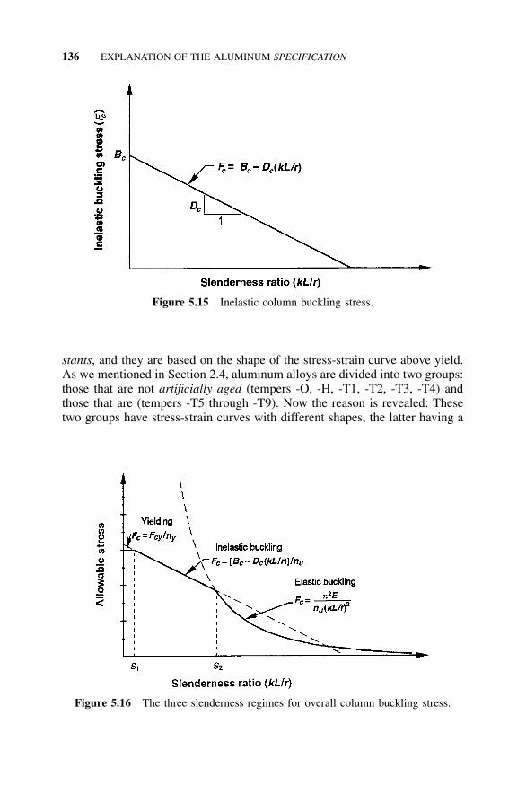
136 EXPLANATION OF THE ALUMINUM SPECIFICATION
Figure 5.15 Inelastic column buckling stress.
Figure 5.16 The three slenderness regimes for overall column buckling stress.
stants, and they are based on the shape of the stress-strain curve above yield.As we mentioned in Section 2.4, aluminum alloys are divided into two groups:those that are not artificially aged (tempers -O, -H, -T1, -T2, -T3, -T4) andthose that are (tempers -T5 through -T9). Now the reason is revealed: Thesetwo groups have stress-strain curves with different shapes, the latter having a
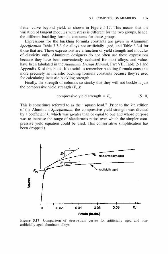
5.2 COMPRESSION MEMBERS 137
Figure 5.17 Comparison of stress-strain curves for artificially aged and non-artificially aged aluminum alloys.
flatter curve beyond yield, as shown in Figure 5.17. This means that thevariation of tangent modulus with stress is different for the two groups, hence,the different buckling formula constants for these groups.
Expressions for the buckling formula constants are given in AluminumSpecification Table 3.3-3 for alloys not artificially aged, and Table 3.3-4 forthose that are. These expressions are a function of yield strength and modulusof elasticity only. Aluminum designers do not often use these expressionsbecause they have been conveniently evaluated for most alloys, and valueshave been tabulated in the Aluminum Design Manual, Part VII, Table 2-1 andAppendix K of this book. It’s useful to remember buckling formula constantsmore precisely as inelastic buckling formula constants because they’re usedfor calculating inelastic buckling strength.
Finally, the strength of columns so stocky that they will not buckle is justthe compressive yield strength (Fcy):
compressive yield strength � F (5.10)cy
This is sometimes referred to as the ‘‘squash load.’’ (Prior to the 7th editionof the Aluminum Specification, the compressive yield strength was dividedby a coefficient kc which was greater than or equal to one and whose purposewas to increase the range of slenderness ratios over which the simpler com-pressive yield equation could be used. This conservative simplification hasbeen dropped.)
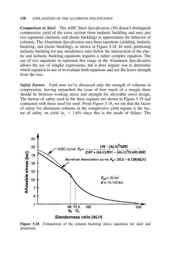
138 EXPLANATION OF THE ALUMINUM SPECIFICATION
Figure 5.18 Comparison of the column buckling stress equations for steel andaluminum.
Comparison to Steel The AISC Steel Specification (39) doesn’t distinguishcompressive yield of the cross section from inelastic buckling and uses justtwo equations (inelastic and elastic buckling) to approximate the behavior ofcolumns. The Aluminum Specification uses three equations (yielding, inelasticbuckling, and elastic buckling), as shown in Figure 5.18. In steel, predictinginelastic buckling for any slenderness ratio below the intersection of the elas-tic and inelastic buckling equations requires a rather complex equation. Theuse of two equations to represent this range in the Aluminum Specificationallows the use of simpler expressions, but it does require you to determinewhich equation to use or to evaluate both equations and use the lesser strengthfrom the two.
Safety Factors Until now we’ve discussed only the strength of columns incompression, leaving untouched the issue of how much of a margin thereshould be between working stress and strength for allowable stress design.The factors of safety used in the three regimes are shown in Figure 5.19 andcontrasted with those used for steel. From Figure 5.19, we see that the factorof safety for aluminum columns in the compressive yield regime is the fac-tor of safety on yield (ny � 1.65) since this is the mode of failure. The
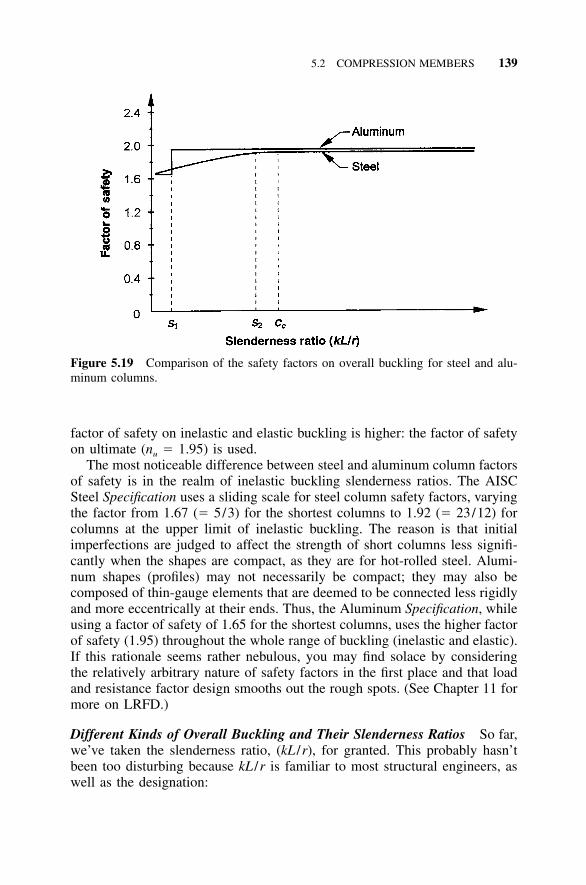
5.2 COMPRESSION MEMBERS 139
Figure 5.19 Comparison of the safety factors on overall buckling for steel and alu-minum columns.
factor of safety on inelastic and elastic buckling is higher: the factor of safetyon ultimate (nu � 1.95) is used.
The most noticeable difference between steel and aluminum column factorsof safety is in the realm of inelastic buckling slenderness ratios. The AISCSteel Specification uses a sliding scale for steel column safety factors, varyingthe factor from 1.67 (� 5/3) for the shortest columns to 1.92 (� 23/12) forcolumns at the upper limit of inelastic buckling. The reason is that initialimperfections are judged to affect the strength of short columns less signifi-cantly when the shapes are compact, as they are for hot-rolled steel. Alumi-num shapes (profiles) may not necessarily be compact; they may also becomposed of thin-gauge elements that are deemed to be connected less rigidlyand more eccentrically at their ends. Thus, the Aluminum Specification, whileusing a factor of safety of 1.65 for the shortest columns, uses the higher factorof safety (1.95) throughout the whole range of buckling (inelastic and elastic).If this rationale seems rather nebulous, you may find solace by consideringthe relatively arbitrary nature of safety factors in the first place and that loadand resistance factor design smooths out the rough spots. (See Chapter 11 formore on LRFD.)
Different Kinds of Overall Buckling and Their Slenderness Ratios So far,we’ve taken the slenderness ratio, (kL /r), for granted. This probably hasn’tbeen too disturbing because kL /r is familiar to most structural engineers, aswell as the designation:
140 EXPLANATION OF THE ALUMINUM SPECIFICATION
� � kL /r (5.11)
where:
k � effective length factor (more on this below)L � length of the column between points of restraint against buckling
(unbraced length)r � radius of gyration of the column about the axis of buckling.
But what is ‘‘the axis of buckling’’ referred to in the definition of r? Here’sa hint: It’s a function of the kind of overall buckling.
Up to this point, we’ve described only one kind of overall buckling, thekind called flexural buckling, demonstrated by the ruler discussed above. Useof the term ‘‘flexural’’ when we’re talking about columns can be confusing,so let’s clarify this. Flexural buckling refers to the lateral bowing of the ruleras it buckles, taking a shape as if it were being bent, even though only anaxial force is applied to the member. This kind of buckling is covered inAluminum Specification Section 3.4.7.1. The axis of buckling is the cross-sectional bending axis about which the flexure occurs, which will be the axiswith the greater slenderness ratio. Because the effective length factor (k) andthe radius of gyration may be different for the two principal axes, designersmust calculate the slenderness ratio for each axis to determine which isgreater. Many engineers are familiar only with this kind of overall buckling,which is sufficient for typical closed shapes (i.e., round and rectangular tube).
How else can columns buckle? Another kind of overall buckling is tor-sional buckling, which is a twisting or corkscrewing of the column. Equal legcruciform sections, which are point symmetric, tend to buckle this way. Nolateral displacement takes place along the member length during buckling,only twisting. The axis of buckling is the longitudinal axis of the member fortorsional buckling. Last, shapes that are not doubly symmetric may buckle inthe overall buckling mode called torsional-flexural buckling, a combinationof twisting and lateral deflection.
A way to treat these buckling modes involving torsion is to replace kL /rwith an ‘‘effective’’ kL /r. A method for determining the effective slendernessratio (kL /r)e for both torsional or torsional-flexural buckling for doubly orsingly symmetric sections is given in Aluminum Specification Section 3.4.7.2.However, the Specification doesn’t provide a method for determining the ef-fective radius of gyration for unsymmetric shapes. Also, designers must al-ready know if a shape is subject to torsional or torsional-flexural buckling inorder to choose which Aluminum Specification Section (3.4.7.1 or 3.4.7.2)applies.
To clear these hurdles, consult Table 5.2, it shows which shapes are subjectto which modes of overall buckling.
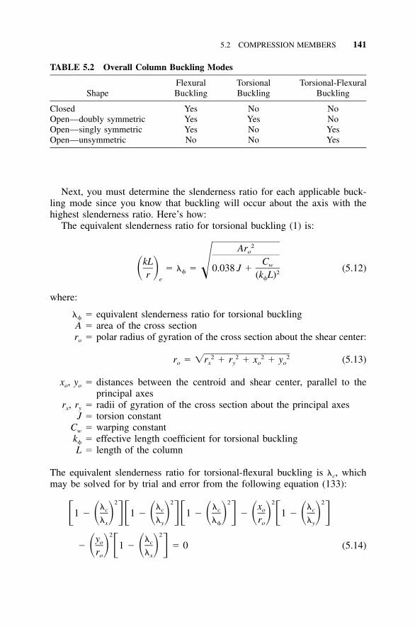
5.2 COMPRESSION MEMBERS 141
TABLE 5.2 Overall Column Buckling Modes
ShapeFlexuralBuckling
TorsionalBuckling
Torsional-FlexuralBuckling
Closed Yes No NoOpen—doubly symmetric Yes Yes NoOpen—singly symmetric Yes No YesOpen—unsymmetric No No Yes
Next, you must determine the slenderness ratio for each applicable buck-ling mode since you know that buckling will occur about the axis with thehighest slenderness ratio. Here’s how:
The equivalent slenderness ratio for torsional buckling (1) is:
2Aro
kL Cw� � � 0.038 J � (5.12)� � � 2r (k L)e
where:
� � equivalent slenderness ratio for torsional bucklingA � area of the cross sectionro � polar radius of gyration of the cross section about the shear center:
2 2 2 2r � �r � r � x � y (5.13)o x y o o
xo, yo � distances between the centroid and shear center, parallel to theprincipal axes
rx, ry � radii of gyration of the cross section about the principal axesJ � torsion constant
Cw � warping constantk � effective length coefficient for torsional bucklingL � length of the column
The equivalent slenderness ratio for torsional-flexural buckling is �c, whichmay be solved for by trial and error from the following equation (133):
2 2 2 2 2� � � x �c c c o c1 � 1 � 1 � � 1 �� � � �� � � �� � � � � � � � � �� � � r �x y o y
2 2y �o c� 1 � � 0 (5.14)� � � � � �r �o x
142 EXPLANATION OF THE ALUMINUM SPECIFICATION
where:
�c � equivalent slenderness ratio for torsional-flexural buckling�x, �y � effective slenderness ratios for flexural buckling about the x and
y axes, respectively� � equivalent slenderness ratio for torsional bucklingro � polar radius of gyration of the cross section about the shear center
(see Equation 5.13)xo, yo � distances between the centroid and shear center, parallel to the
principal axes.
Formulas for the torsion constant (J) and the warping constant (Cw) for severalkinds of shapes are given in the Aluminum Design Manual, Part VI, Table29. Calculated values for the torsion and warping constants for the AluminumAssociation standard I-beams and channels are not given in the AluminumDesign Manual, but we have calculated them. You can find them in Appen-dix B.
The Effective Length Factor (k) The effective length factor (k) is multipliedby the actual unbraced column length (L) to obtain the length between pointsof inflection, or the length of Euler’s pin-ended column. The k factor is ameasure of the restraint against rotation and the resistance to lateral deflectionat the ends of the unbraced length. Figure 5.20 gives k values for variouscases. Aluminum Specification Section 3.2, Nomenclature, requires that k betaken as larger than or equal to 1 ‘‘unless rational analysis justifies a smallervalue.’’
The effective length factor is determined for each kind of overall buckling(flexural or torsional), based on the restraint to rotation about the axis ofbuckling rotation. If the mode of buckling is flexural, k is based on the re-straint placed on the column ends against bending rotation. If the mode ofbuckling is torsional, k is based on the restraint on the column ends againstrotation about the member’s longitudinal axis (twisting and warping).
Deviation from Straight The tests (133) used to establish aluminum columnbuckling strengths limited the initial crookedness of the columns to less thanL /1000. For this degree of crookedness, the column strength is 80% of thatof a perfectly straight column. The Aluminum Association allows a mill tol-erance of L /960 for most prismatic member products in Aluminum Standardsand Data (11), and AWS D1.2 Structural Welding Code—Aluminum (91) hasthe same tolerance on straightness of welded members. This slight unconser-vatism was justified by recognizing that in practice columns idealized as pin-ended have an effective k of less than 1 due to partial restraint against rotationat end connections, even though columns idealized as having ends fixedagainst rotation are not completely fixed in practice. Beware that Aluminum
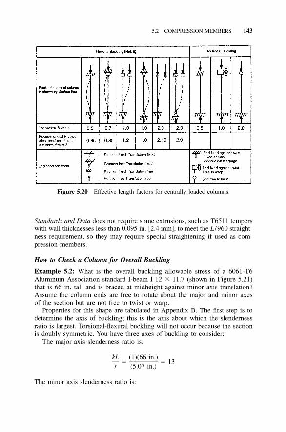
5.2 COMPRESSION MEMBERS 143
Figure 5.20 Effective length factors for centrally loaded columns.
Standards and Data does not require some extrusions, such as T6511 temperswith wall thicknesses less than 0.095 in. [2.4 mm], to meet the L /960 straight-ness requirement, so they may require special straightening if used as com-pression members.
How to Check a Column for Overall Buckling
Example 5.2: What is the overall buckling allowable stress of a 6061-T6Aluminum Association standard I-beam I 12 � 11.7 (shown in Figure 5.21)that is 66 in. tall and is braced at midheight against minor axis translation?Assume the column ends are free to rotate about the major and minor axesof the section but are not free to twist or warp.
Properties for this shape are tabulated in Appendix B. The first step is todetermine the axis of buckling; this is the axis about which the slendernessratio is largest. Torsional-flexural buckling will not occur because the sectionis doubly symmetric. You have three axes of buckling to consider:
The major axis slenderness ratio is:
kL (1)(66 in.)� � 13
r (5.07 in.)
The minor axis slenderness ratio is:
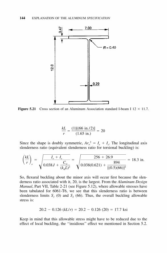
144 EXPLANATION OF THE ALUMINUM SPECIFICATION
Figure 5.21 Cross section of an Aluminum Association standard I-beam I 12 � 11.7.
kL (1)[(66 in. /2)]� � 20
r (1.65 in.)
Since the shape is doubly symmetric, Aro2 � Ix � Iy. The longitudinal axis
slenderness ratio (equivalent slenderness ratio for torsional buckling) is:
kL I � I 256 � 26.9x y� � � 18.3 in.� �r C 894we 0.038J � 0.038(0.621) �� �2 2(k L) [(0.5)(66)]
So, flexural buckling about the minor axis will occur first because the slen-derness ratio associated with it, 20, is the largest. From the Aluminum DesignManual, Part VII, Table 2-21 (see Figure 5.12), where allowable stresses havebeen tabulated for 6061-T6, we see that this slenderness ratio is betweenslenderness limits S1 (0) and S2 (66). Thus, the overall buckling allowablestress is:
20.2 � 0.126 (kL /r) � 20.2 � 0.126 (20) � 17.7 ksi
Keep in mind that this allowable stress might have to be reduced due to theeffect of local buckling, the ‘‘insidious’’ effect we mentioned in Section 5.2.
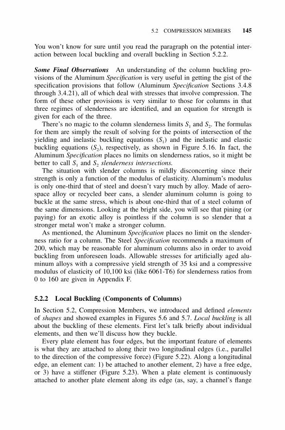
5.2 COMPRESSION MEMBERS 145
You won’t know for sure until you read the paragraph on the potential inter-action between local buckling and overall buckling in Section 5.2.2.
Some Final Observations An understanding of the column buckling pro-visions of the Aluminum Specification is very useful in getting the gist of thespecification provisions that follow (Aluminum Specification Sections 3.4.8through 3.4.21), all of which deal with stresses that involve compression. Theform of these other provisions is very similar to those for columns in thatthree regimes of slenderness are identified, and an equation for strength isgiven for each of the three.
There’s no magic to the column slenderness limits S1 and S2. The formulasfor them are simply the result of solving for the points of intersection of theyielding and inelastic buckling equations (S1) and the inelastic and elasticbuckling equations (S2), respectively, as shown in Figure 5.16. In fact, theAluminum Specification places no limits on slenderness ratios, so it might bebetter to call S1 and S2 slenderness intersections.
The situation with slender columns is mildly disconcerting since theirstrength is only a function of the modulus of elasticity. Aluminum’s modulusis only one-third that of steel and doesn’t vary much by alloy. Made of aero-space alloy or recycled beer cans, a slender aluminum column is going tobuckle at the same stress, which is about one-third that of a steel column ofthe same dimensions. Looking at the bright side, you will see that pining (orpaying) for an exotic alloy is pointless if the column is so slender that astronger metal won’t make a stronger column.
As mentioned, the Aluminum Specification places no limit on the slender-ness ratio for a column. The Steel Specification recommends a maximum of200, which may be reasonable for aluminum columns also in order to avoidbuckling from unforeseen loads. Allowable stresses for artificially aged alu-minum alloys with a compressive yield strength of 35 ksi and a compressivemodulus of elasticity of 10,100 ksi (like 6061-T6) for slenderness ratios from0 to 160 are given in Appendix F.
5.2.2 Local Buckling (Components of Columns)
In Section 5.2, Compression Members, we introduced and defined elementsof shapes and showed examples in Figures 5.6 and 5.7. Local buckling is allabout the buckling of these elements. First let’s talk briefly about individualelements, and then we’ll discuss how they buckle.
Every plate element has four edges, but the important feature of elementsis what they are attached to along their two longitudinal edges (i.e., parallelto the direction of the compressive force) (Figure 5.22). Along a longitudinaledge, an element can: 1) be attached to another element, 2) have a free edge,or 3) have a stiffener (Figure 5.23). When a plate element is continuouslyattached to another plate element along its edge (as, say, a channel’s flange
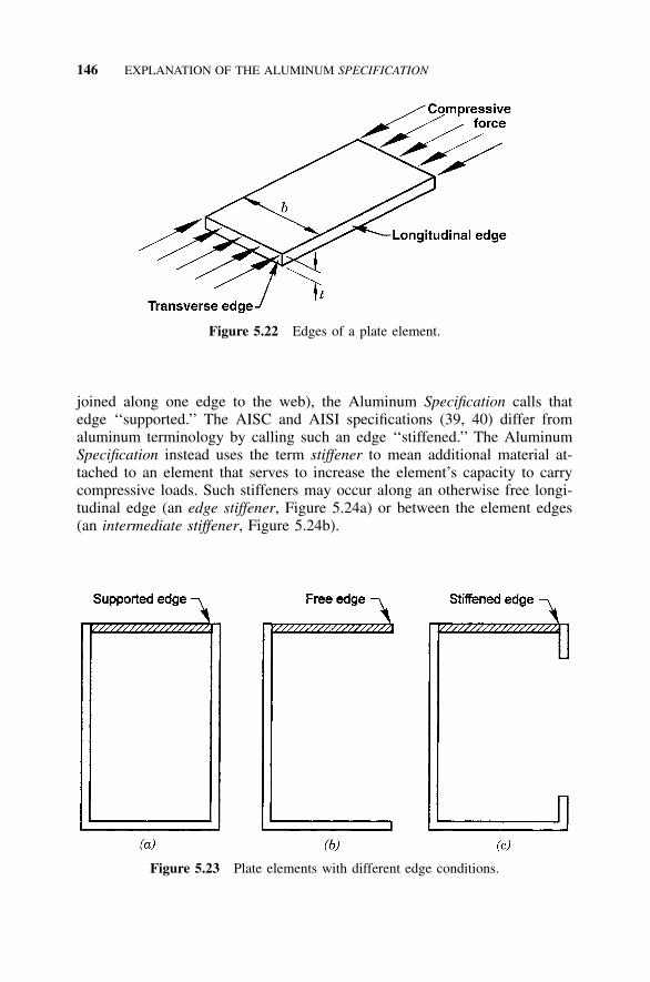
146 EXPLANATION OF THE ALUMINUM SPECIFICATION
Figure 5.22 Edges of a plate element.
Figure 5.23 Plate elements with different edge conditions.
joined along one edge to the web), the Aluminum Specification calls thatedge ‘‘supported.’’ The AISC and AISI specifications (39, 40) differ fromaluminum terminology by calling such an edge ‘‘stiffened.’’ The AluminumSpecification instead uses the term stiffener to mean additional material at-tached to an element that serves to increase the element’s capacity to carrycompressive loads. Such stiffeners may occur along an otherwise free longi-tudinal edge (an edge stiffener, Figure 5.24a) or between the element edges(an intermediate stiffener, Figure 5.24b).
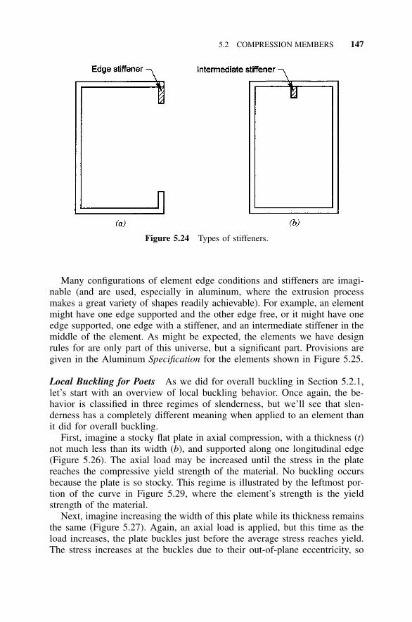
5.2 COMPRESSION MEMBERS 147
Figure 5.24 Types of stiffeners.
Many configurations of element edge conditions and stiffeners are imagi-nable (and are used, especially in aluminum, where the extrusion processmakes a great variety of shapes readily achievable). For example, an elementmight have one edge supported and the other edge free, or it might have oneedge supported, one edge with a stiffener, and an intermediate stiffener in themiddle of the element. As might be expected, the elements we have designrules for are only part of this universe, but a significant part. Provisions aregiven in the Aluminum Specification for the elements shown in Figure 5.25.
Local Buckling for Poets As we did for overall buckling in Section 5.2.1,let’s start with an overview of local buckling behavior. Once again, the be-havior is classified in three regimes of slenderness, but we’ll see that slen-derness has a completely different meaning when applied to an element thanit did for overall buckling.
First, imagine a stocky flat plate in axial compression, with a thickness (t)not much less than its width (b), and supported along one longitudinal edge(Figure 5.26). The axial load may be increased until the stress in the platereaches the compressive yield strength of the material. No buckling occursbecause the plate is so stocky. This regime is illustrated by the leftmost por-tion of the curve in Figure 5.29, where the element’s strength is the yieldstrength of the material.
Next, imagine increasing the width of this plate while its thickness remainsthe same (Figure 5.27). Again, an axial load is applied, but this time as theload increases, the plate buckles just before the average stress reaches yield.The stress increases at the buckles due to their out-of-plane eccentricity, so
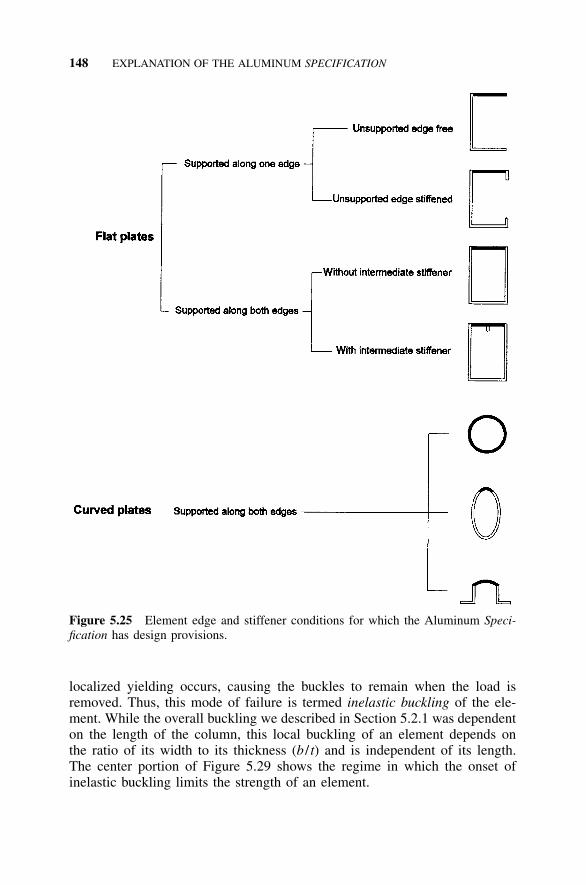
148 EXPLANATION OF THE ALUMINUM SPECIFICATION
Figure 5.25 Element edge and stiffener conditions for which the Aluminum Speci-fication has design provisions.
localized yielding occurs, causing the buckles to remain when the load isremoved. Thus, this mode of failure is termed inelastic buckling of the ele-ment. While the overall buckling we described in Section 5.2.1 was dependenton the length of the column, this local buckling of an element depends onthe ratio of its width to its thickness (b / t) and is independent of its length.The center portion of Figure 5.29 shows the regime in which the onset ofinelastic buckling limits the strength of an element.
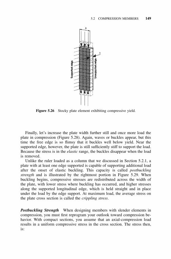
5.2 COMPRESSION MEMBERS 149
Figure 5.26 Stocky plate element exhibiting compressive yield.
Finally, let’s increase the plate width further still and once more load theplate in compression (Figure 5.28). Again, waves or buckles appear, but thistime the free edge is so flimsy that it buckles well below yield. Near thesupported edge, however, the plate is still sufficiently stiff to support the load.Because the stress is in the elastic range, the buckles disappear when the loadis removed.
Unlike the ruler loaded as a column that we discussed in Section 5.2.1, aplate with at least one edge supported is capable of supporting additional loadafter the onset of elastic buckling. This capacity is called postbucklingstrength and is illustrated by the rightmost portion in Figure 5.29. Whenbuckling begins, compressive stresses are redistributed across the width ofthe plate, with lower stress where buckling has occurred, and higher stressesalong the supported longitudinal edge, which is held straight and in placeunder the load by the edge support. At maximum load, the average stress onthe plate cross section is called the crippling stress.
Postbuckling Strength When designing members with slender elements incompression, you must first reprogram your outlook toward compression be-havior. With compact sections, you assume that an axial-compression loadresults in a uniform compressive stress in the cross section. The stress then,is:
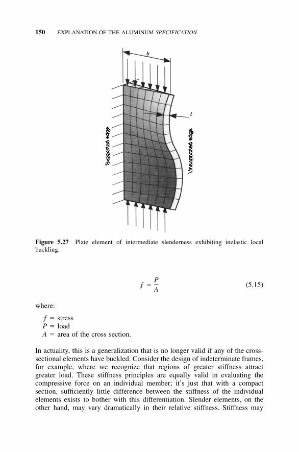
150 EXPLANATION OF THE ALUMINUM SPECIFICATION
Figure 5.27 Plate element of intermediate slenderness exhibiting inelastic localbuckling.
Pƒ � (5.15)
A
where:
ƒ � stressP � loadA � area of the cross section.
In actuality, this is a generalization that is no longer valid if any of the cross-sectional elements have buckled. Consider the design of indeterminate frames,for example, where we recognize that regions of greater stiffness attractgreater load. These stiffness principles are equally valid in evaluating thecompressive force on an individual member; it’s just that with a compactsection, sufficiently little difference between the stiffness of the individualelements exists to bother with this differentiation. Slender elements, on theother hand, may vary dramatically in their relative stiffness. Stiffness may
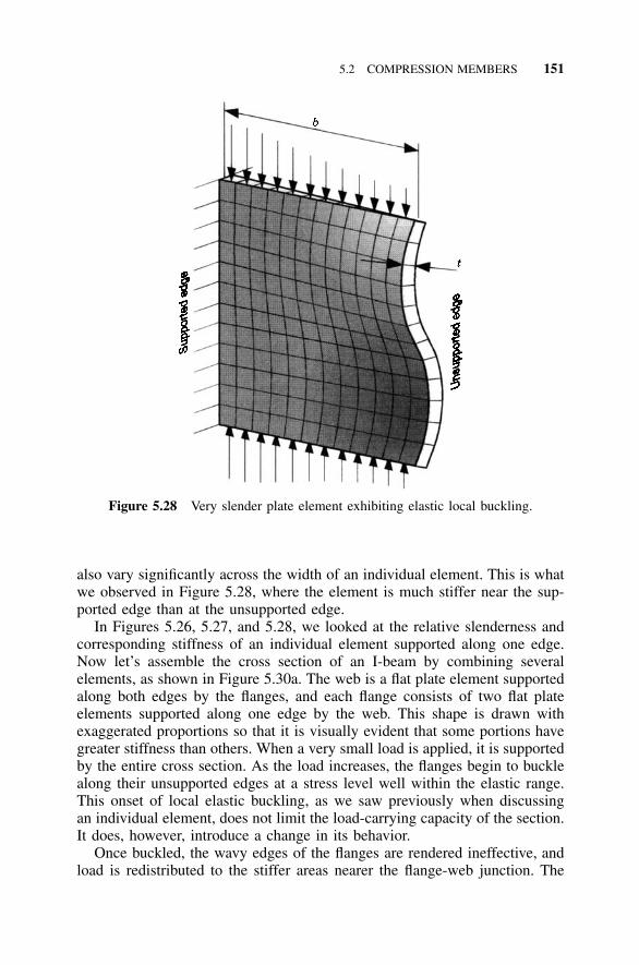
5.2 COMPRESSION MEMBERS 151
Figure 5.28 Very slender plate element exhibiting elastic local buckling.
also vary significantly across the width of an individual element. This is whatwe observed in Figure 5.28, where the element is much stiffer near the sup-ported edge than at the unsupported edge.
In Figures 5.26, 5.27, and 5.28, we looked at the relative slenderness andcorresponding stiffness of an individual element supported along one edge.Now let’s assemble the cross section of an I-beam by combining severalelements, as shown in Figure 5.30a. The web is a flat plate element supportedalong both edges by the flanges, and each flange consists of two flat plateelements supported along one edge by the web. This shape is drawn withexaggerated proportions so that it is visually evident that some portions havegreater stiffness than others. When a very small load is applied, it is supportedby the entire cross section. As the load increases, the flanges begin to bucklealong their unsupported edges at a stress level well within the elastic range.This onset of local elastic buckling, as we saw previously when discussingan individual element, does not limit the load-carrying capacity of the section.It does, however, introduce a change in its behavior.
Once buckled, the wavy edges of the flanges are rendered ineffective, andload is redistributed to the stiffer areas nearer the flange-web junction. The
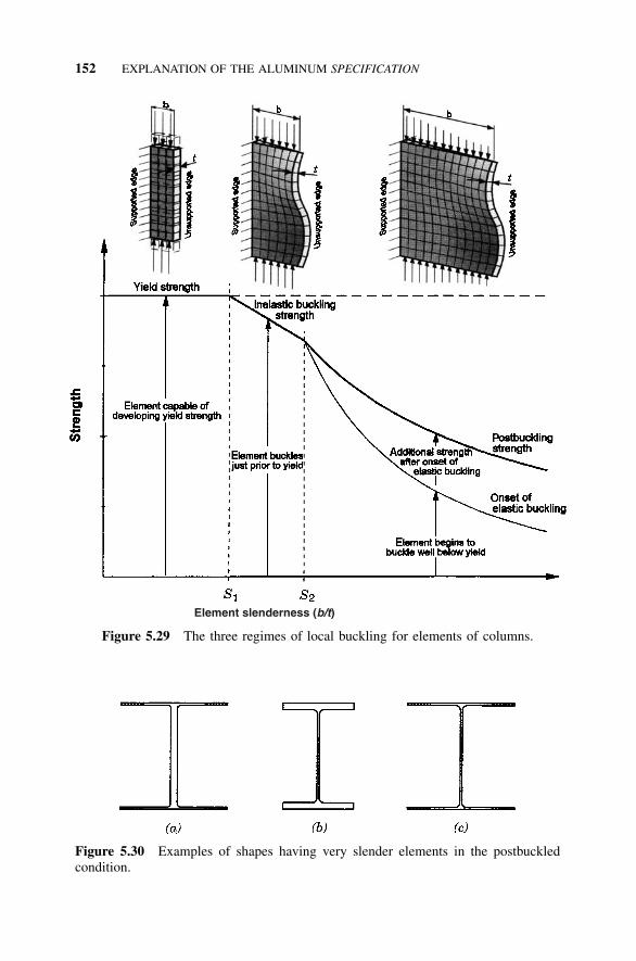
152 EXPLANATION OF THE ALUMINUM SPECIFICATION
Element slenderness (b/t)
Figure 5.29 The three regimes of local buckling for elements of columns.
Figure 5.30 Examples of shapes having very slender elements in the postbuckledcondition.
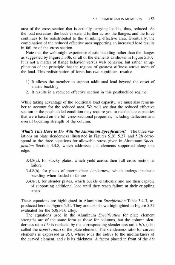
5.2 COMPRESSION MEMBERS 153
area of the cross section that is actually carrying load is, thus, reduced. Asthe load increases, the buckles extend further across the flanges, and the forcecontinues to be redistributed to the shrinking effective area. Eventually, thecombination of the reduced effective area supporting an increased load resultsin failure of the cross section.
Note that the web might experience elastic buckling rather than the flangesas suggested by Figure 5.30b, or all of the elements as shown in Figure 5.30c.It is not a matter of flange behavior versus web behavior, but rather an ap-plication of the principle that the regions of greatest stiffness attract more ofthe load. This redistribution of force has two significant results:
1) It allows the member to support additional load beyond the onset ofelastic buckling
2) It results in a reduced effective section in this postbuckled regime.
While taking advantage of the additional load capacity, we must also remem-ber to account for the reduced area. We will see that the reduced effectivesection in the postbuckled condition may require you to recalculate capacitiesthat were based on the full cross-sectional properties, including deflection andoverall buckling strength of the column.
What’s This Have to Do With the Aluminum Specification? The three var-iations on plate slenderness illustrated in Figures 5.26, 5.27, and 5.28 corre-spond to the three equations for allowable stress given in Aluminum Speci-fication Section 3.4.8, which addresses flat elements supported along oneedge:
3.4.8(a), for stocky plates, which yield across their full cross section atfailure
3.4.8(b), for plates of intermediate slenderness, which undergo inelasticbuckling when loaded to failure
3.4.8(c), for slender plates, which buckle elastically and are then capableof supporting additional load until they reach failure at their cripplingstress.
These equations are highlighted in Aluminum Specification Table 3.4-3, re-produced here as Figure 5.31. They are also shown highlighted in Figure 5.32evaluated for the 6061-T6 alloy.
The equations used in the Aluminum Specification for plate elementstrengths are of the same form as those for columns, but the column slen-derness ratio L /r is replaced by the corresponding slenderness ratio, b / t, (alsocalled the aspect ratio) of the plate element. The slenderness ratio for curvedelements is expressed as R / t, where R is the radius to the midthickness ofthe curved element, and t is its thickness. A factor placed in front of the b / t
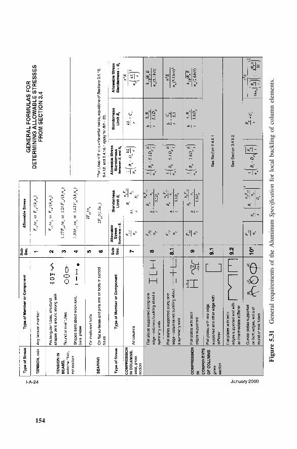
154
Fig
ure
5.31
Gen
eral
requ
irem
ents
ofth
eA
lum
inum
Spec
ifica
tion
for
loca
lbu
cklin
gof
colu
mn
elem
ents
.
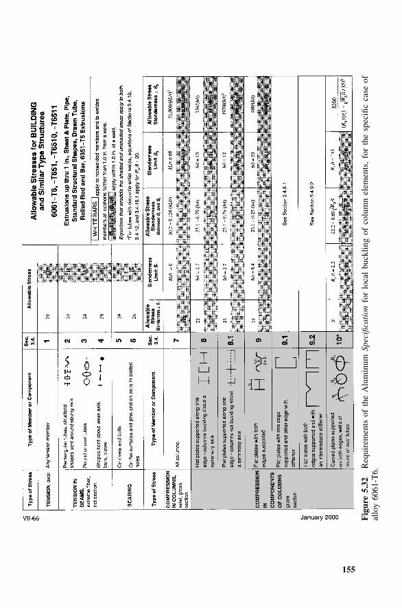
155
Fig
ure
5.32
Req
uire
men
tsof
the
Alu
min
umSp
ecifi
cati
onfo
rlo
cal
buck
ling
ofco
lum
nel
emen
ts,
for
the
spec
ific
case
ofal
loy
6061
-T6.
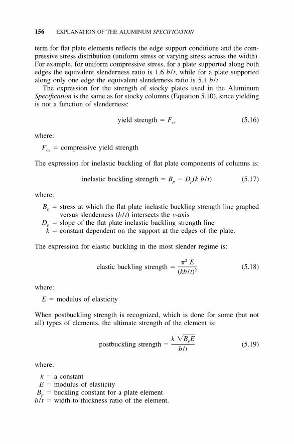
156 EXPLANATION OF THE ALUMINUM SPECIFICATION
term for flat plate elements reflects the edge support conditions and the com-pressive stress distribution (uniform stress or varying stress across the width).For example, for uniform compressive stress, for a plate supported along bothedges the equivalent slenderness ratio is 1.6 b / t, while for a plate supportedalong only one edge the equivalent slenderness ratio is 5.1 b / t.
The expression for the strength of stocky plates used in the AluminumSpecification is the same as for stocky columns (Equation 5.10), since yieldingis not a function of slenderness:
yield strength � F (5.16)cy
where:
Fcy � compressive yield strength
The expression for inelastic buckling of flat plate components of columns is:
inelastic buckling strength � B � D (k b / t) (5.17)p p
where:
Bp � stress at which the flat plate inelastic buckling strength line graphedversus slenderness (b / t) intersects the y-axis
Dp � slope of the flat plate inelastic buckling strength linek � constant dependent on the support at the edges of the plate.
The expression for elastic buckling in the most slender regime is:
2� Eelastic buckling strength � (5.18)2(kb / t)
where:
E � modulus of elasticity
When postbuckling strength is recognized, which is done for some (but notall) types of elements, the ultimate strength of the element is:
k �B Eppostbuckling strength � (5.19)
b / t
where:
k � a constantE � modulus of elasticity
Bp � buckling constant for a plate elementb / t � width-to-thickness ratio of the element.
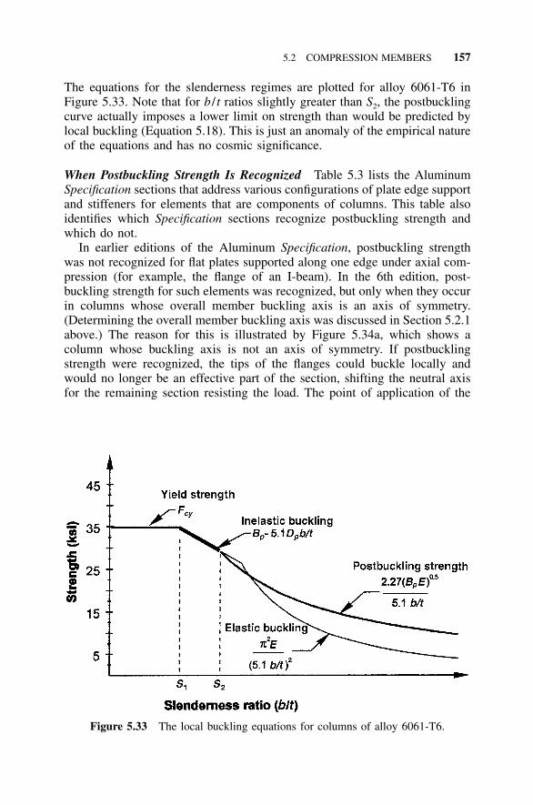
5.2 COMPRESSION MEMBERS 157
Figure 5.33 The local buckling equations for columns of alloy 6061-T6.
The equations for the slenderness regimes are plotted for alloy 6061-T6 inFigure 5.33. Note that for b / t ratios slightly greater than S2, the postbucklingcurve actually imposes a lower limit on strength than would be predicted bylocal buckling (Equation 5.18). This is just an anomaly of the empirical natureof the equations and has no cosmic significance.
When Postbuckling Strength Is Recognized Table 5.3 lists the AluminumSpecification sections that address various configurations of plate edge supportand stiffeners for elements that are components of columns. This table alsoidentifies which Specification sections recognize postbuckling strength andwhich do not.
In earlier editions of the Aluminum Specification, postbuckling strengthwas not recognized for flat plates supported along one edge under axial com-pression (for example, the flange of an I-beam). In the 6th edition, post-buckling strength for such elements was recognized, but only when they occurin columns whose overall member buckling axis is an axis of symmetry.(Determining the overall member buckling axis was discussed in Section 5.2.1above.) The reason for this is illustrated by Figure 5.34a, which shows acolumn whose buckling axis is not an axis of symmetry. If postbucklingstrength were recognized, the tips of the flanges could buckle locally andwould no longer be an effective part of the section, shifting the neutral axisfor the remaining section resisting the load. The point of application of the
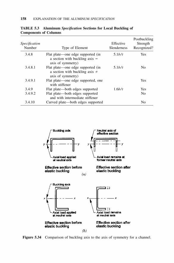
158 EXPLANATION OF THE ALUMINUM SPECIFICATION
TABLE 5.3 Aluminum Specification Sections for Local Buckling ofComponents of Columns
SpecificationNumber Type of Element
EffectiveSlenderness
PostbucklingStrength
Recognized?
3.4.8 Flat plate—one edge supported (ina section with buckling axis �axis of symmetry)
5.1b/ t Yes
3.4.8.1 Flat plate—one edge supported (ina section with buckling axis �axis of symmetry)
5.1b/ t No
3.4.9.1 Flat plate—one edge supported, onewith stiffener
Yes
3.4.9 Flat plate—both edges supported 1.6b/ t Yes3.4.9.2 Flat plate—both edges supported
and with intermediate stiffenerNo
3.4.10 Curved plate—both edges supported No
Figure 5.34 Comparison of buckling axis to the axis of symmetry for a channel.
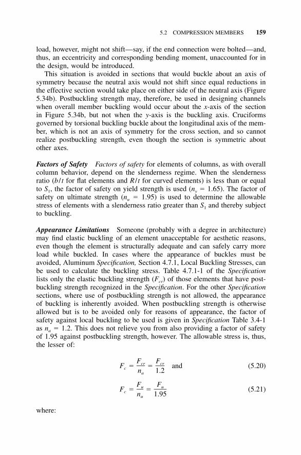
5.2 COMPRESSION MEMBERS 159
load, however, might not shift—say, if the end connection were bolted—and,thus, an eccentricity and corresponding bending moment, unaccounted for inthe design, would be introduced.
This situation is avoided in sections that would buckle about an axis ofsymmetry because the neutral axis would not shift since equal reductions inthe effective section would take place on either side of the neutral axis (Figure5.34b). Postbuckling strength may, therefore, be used in designing channelswhen overall member buckling would occur about the x-axis of the sectionin Figure 5.34b, but not when the y-axis is the buckling axis. Cruciformsgoverned by torsional buckling buckle about the longitudinal axis of the mem-ber, which is not an axis of symmetry for the cross section, and so cannotrealize postbuckling strength, even though the section is symmetric aboutother axes.
Factors of Safety Factors of safety for elements of columns, as with overallcolumn behavior, depend on the slenderness regime. When the slendernessratio (b / t for flat elements and R / t for curved elements) is less than or equalto S1, the factor of safety on yield strength is used (ny � 1.65). The factor ofsafety on ultimate strength (nu � 1.95) is used to determine the allowablestress of elements with a slenderness ratio greater than S1 and thereby subjectto buckling.
Appearance Limitations Someone (probably with a degree in architecture)may find elastic buckling of an element unacceptable for aesthetic reasons,even though the element is structurally adequate and can safely carry moreload while buckled. In cases where the appearance of buckles must beavoided, Aluminum Specification, Section 4.7.1, Local Buckling Stresses, canbe used to calculate the buckling stress. Table 4.7.1-1 of the Specificationlists only the elastic buckling strength (Fcr) of those elements that have post-buckling strength recognized in the Specification. For the other Specificationsections, where use of postbuckling strength is not allowed, the appearanceof buckling is inherently avoided. When postbuckling strength is otherwiseallowed but is to be avoided only for reasons of appearance, the factor ofsafety against local buckling to be used is given in Specification Table 3.4-1as na � 1.2. This does not relieve you from also providing a factor of safetyof 1.95 against postbuckling strength, however. The allowable stress is, thus,the lesser of:
F Fcr crF � � and (5.20)c n 1.2a
F Fu uF � � (5.21)c n 1.95u
where:
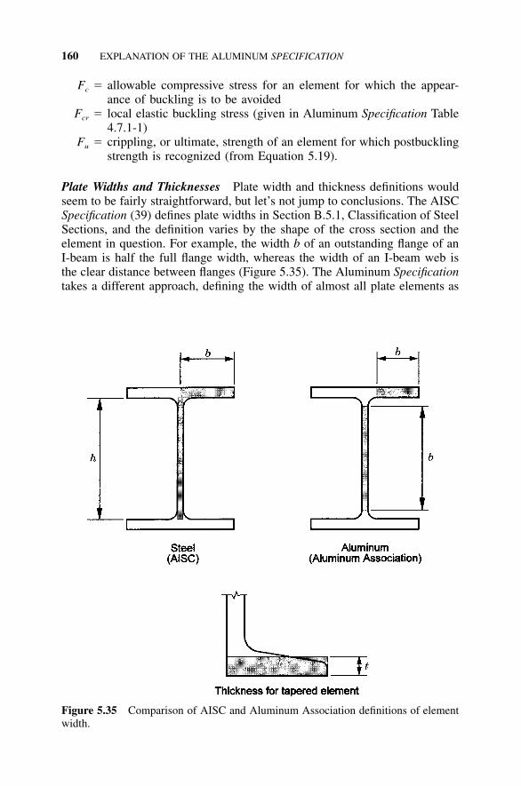
160 EXPLANATION OF THE ALUMINUM SPECIFICATION
Figure 5.35 Comparison of AISC and Aluminum Association definitions of elementwidth.
Fc � allowable compressive stress for an element for which the appear-ance of buckling is to be avoided
Fcr � local elastic buckling stress (given in Aluminum Specification Table4.7.1-1)
Fu � crippling, or ultimate, strength of an element for which postbucklingstrength is recognized (from Equation 5.19).
Plate Widths and Thicknesses Plate width and thickness definitions wouldseem to be fairly straightforward, but let’s not jump to conclusions. The AISCSpecification (39) defines plate widths in Section B.5.1, Classification of SteelSections, and the definition varies by the shape of the cross section and theelement in question. For example, the width b of an outstanding flange of anI-beam is half the full flange width, whereas the width of an I-beam web isthe clear distance between flanges (Figure 5.35). The Aluminum Specificationtakes a different approach, defining the width of almost all plate elements as
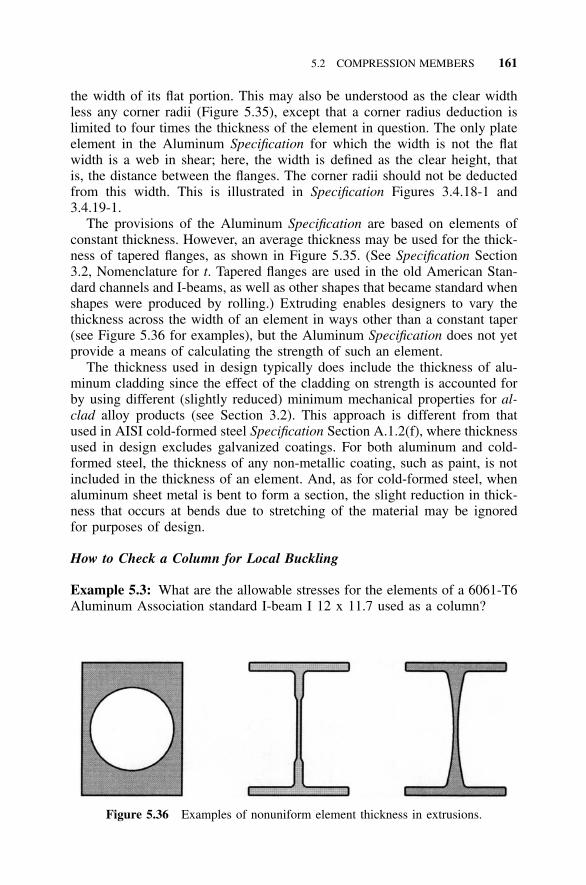
5.2 COMPRESSION MEMBERS 161
Figure 5.36 Examples of nonuniform element thickness in extrusions.
the width of its flat portion. This may also be understood as the clear widthless any corner radii (Figure 5.35), except that a corner radius deduction islimited to four times the thickness of the element in question. The only plateelement in the Aluminum Specification for which the width is not the flatwidth is a web in shear; here, the width is defined as the clear height, thatis, the distance between the flanges. The corner radii should not be deductedfrom this width. This is illustrated in Specification Figures 3.4.18-1 and3.4.19-1.
The provisions of the Aluminum Specification are based on elements ofconstant thickness. However, an average thickness may be used for the thick-ness of tapered flanges, as shown in Figure 5.35. (See Specification Section3.2, Nomenclature for t. Tapered flanges are used in the old American Stan-dard channels and I-beams, as well as other shapes that became standard whenshapes were produced by rolling.) Extruding enables designers to vary thethickness across the width of an element in ways other than a constant taper(see Figure 5.36 for examples), but the Aluminum Specification does not yetprovide a means of calculating the strength of such an element.
The thickness used in design typically does include the thickness of alu-minum cladding since the effect of the cladding on strength is accounted forby using different (slightly reduced) minimum mechanical properties for al-clad alloy products (see Section 3.2). This approach is different from thatused in AISI cold-formed steel Specification Section A.1.2(f), where thicknessused in design excludes galvanized coatings. For both aluminum and cold-formed steel, the thickness of any non-metallic coating, such as paint, is notincluded in the thickness of an element. And, as for cold-formed steel, whenaluminum sheet metal is bent to form a section, the slight reduction in thick-ness that occurs at bends due to stretching of the material may be ignoredfor purposes of design.
How to Check a Column for Local Buckling
Example 5.3: What are the allowable stresses for the elements of a 6061-T6Aluminum Association standard I-beam I 12 x 11.7 used as a column?
162 EXPLANATION OF THE ALUMINUM SPECIFICATION
Dimensions for this shape are given in Aluminum Design Manual, Part VI,Table 11, and shown on Figure 5.21 here. You can divide the cross sectionof this I-beam into 5 elements: two for each of the two flanges, and one beingthe web. The flange elements are all the same: flat plates supported along oneedge (where they join to the web); these are addressed in Aluminum Speci-fication Section 3.4.8. The web is a flat plate with both edges supported(where it joins to the flanges) and addressed in Aluminum Specification Sec-tion 3.4.9. Thus, you have two unique elements to investigate: flange andweb.
The flat width of each flange element is:
[(7 in.) � (0.29 in.) � 2(0.4 in.)]� 2.955 in.
2
The flange-to-web fillet radius is 0.4 in. � 4t � 4(0.47 in.) � 1.88 in., so theentire radius may be deducted from the width. The width-to-thickness, orslenderness, ratio is:
b 2.955 in.� � 6.29
t 0.47 in.
Referencing the Aluminum Design Manual, Part VII, Design Aids Table 2-21(Figure 5.32), which gives allowable stresses for 6061-T6 aluminum, we find,for Specification Section 3.4.8, that this slenderness ratio is between the slen-derness limits S1 (2.7) and S2 (10). (This means the flange strength is basedon inelastic buckling.) The allowable stress for the flanges can be determinedfrom the equation found in Figure 5.32:
23.1 � 0.79(b / t) � 23.1 � 0.79(6.29) � 18.1 ksi.
The flat width of the web is:
(12 in.) � 2[(0.4 in.) � (0.47 in.)] � 10.26 in.
The flange-to-web fillet radius is 0.4 in. � 4t � 4(0.29 in.) � 1.16 in., so theentire radius may be deducted from the width. The width-to-thickness, orslenderness, ratio is:
b 10.26 in.� � 35.38
t 0.29 in.
Referring again to Figure 5.32, we find that, for Specification Section 3.4.9,35.38 � 33 � S2, so the allowable stress for the web is:
5.2 COMPRESSION MEMBERS 163
490� 13.8 ksi
b / t
From Table 5.3, we see that postbuckling strength is recognized in Section3.4.9, and since the web’s slenderness ratio is greater than S2, the web strengthis a postbuckling strength.
The local buckling allowable stress of the cross section could be conser-vatively taken as the lesser of the allowable stresses for the flange (18.1) andweb (13.8), or 13.8 ksi. However, a less conservative approach for determin-ing the allowable stress of the elements of the column, called the weightedaverage allowable stress method, is permitted by the Aluminum Specification.
Weighted Average Allowable Compressive Stress Aluminum SpecificationSection 4.7.2, Weighted Average Allowable Compressive Stress, permits analternate calculation of local buckling strength, recognizing the nonuniformdistribution of stress in the cross section. This method determines the localbuckling allowable stress as the weighted average allowable stress for theindividual elements, where the allowable stress for each element is weightedin accordance with the ratio of the area of the element to the total area of thesection. Perhaps a simpler way of understanding this is to consider it to be amethod by which the strength of each element is calculated, and the strengthof the section is taken as the sum of the strength of the elements.
The weighted average allowable stress is determined by the followingequation:
A F � A F � ��� � A F1 c1 2 c2 n cnF � (5.22)ca A
where:
Ai � area of element iFci � allowable stress of element iA � area of the cross section (� A1 � A2 � ��� � An),
Fca � the weighted average allowable stress.
The weighted average method may be applied to elements of any slendernessand is illustrated as a continuation of Example 5.3.
Example 5.4: What is the weighted average allowable stress for the I-beamof Example 5.3 above?
The allowable stress for the flange was determined in Example 5.3 to be18.1 ksi, and the allowable stress for the web was 13.8 ksi. The area of theflanges is:
164 EXPLANATION OF THE ALUMINUM SPECIFICATION
22(7 in.)(0.47 in.) � 6.58 in
The area of the web is:
2(0.29 in.)[12 � 2(.47)] in. � 3.21 in
The weighted average allowable stress is:
(18.1)(6.58) � (13.8)(3.21)F � � 16.7 ksica 6.58 � 3.21
This value is 21% higher than the 13.8 ksi stress obtained by using theminimum of the flange and web allowable stresses.
As we mentioned previously and the above examples illustrate, the localbuckling strengths are only a function of the dimensions of the member crosssection, not its length or end supports. Therefore, you can determine localbuckling strengths for cross sections and tabulate them for convenience.We’ve done this for you in Appendix D for Aluminum Association StandardI-beams and Aluminum Association Standard channels.
Effective Width Another approach for determining the postbuckling strengthof sections is the effective width method. Aluminum Specification Section4.7.6 employs only the effective width method to compute the deflections ofsections with very slender elements. We’ll see that this usually is not a con-cern with extrusions.
The effective width method is required in the AISI’s cold-formed steelSpecification to determine both stresses and deflections for light-gauge steeldesign, whereas the Aluminum Specification uses the much simpler weightedaverage approach to calculate allowable stress. The steel approach requiresthat you know the stress in an element to calculate its effective width. Toknow the stress, however, you must already know the effective width of eachelement in order to calculate the section’s properties. Consequently, the pro-cedure is iterative.
While the weighted average method is simpler and gives results for strengthsimilar to those of the effective width method, it does not afford a way tocalculate deflections in the postbuckled regime. The effective width methodmust, therefore, be used to calculate deflections of members with elements inthe postbuckled condition, but the Aluminum Specification avoids the iterativeprocess because the stress at design loads is already given by the weightedaverage method. Aluminum Specification Section 4.7.6 obtains the effectivewidth of an element by solving in terms of the calculated stress:
b � b �F /ƒ (5.23)e cr c
where:
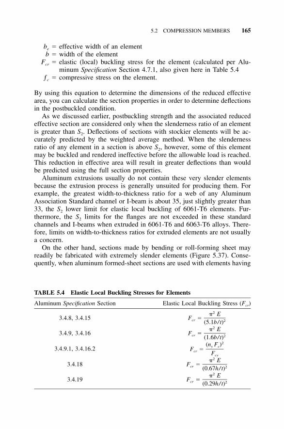
5.2 COMPRESSION MEMBERS 165
TABLE 5.4 Elastic Local Buckling Stresses for Elements
Aluminum Specification Section Elastic Local Buckling Stress (Fcr)
3.4.8, 3.4.152� E
F �cr 2(5.1b/ t)
3.4.9, 3.4.162� E
F �cr 2(1.6b/ t)
3.4.9.1, 3.4.16.22(n F )y c
F �cr Fcy
3.4.182� E
F �cr 2(0.67h/ t)
3.4.192� E
F �cr 2(0.29h/ t)
be � effective width of an elementb � width of the element
Fcr � elastic (local) buckling stress for the element (calculated per Alu-minum Specification Section 4.7.1, also given here in Table 5.4
ƒc � compressive stress on the element.
By using this equation to determine the dimensions of the reduced effectivearea, you can calculate the section properties in order to determine deflectionsin the postbuckled condition.
As we discussed earlier, postbuckling strength and the associated reducedeffective section are considered only when the slenderness ratio of an elementis greater than S2. Deflections of sections with stockier elements will be ac-curately predicted by the weighted average method. When the slendernessratio of any element in a section is above S2, however, some of this elementmay be buckled and rendered ineffective before the allowable load is reached.This reduction in effective area will result in greater deflections than wouldbe predicted using the full section properties.
Aluminum extrusions usually do not contain these very slender elementsbecause the extrusion process is generally unsuited for producing them. Forexample, the greatest width-to-thickness ratio for a web of any AluminumAssociation Standard channel or I-beam is about 35, just slightly greater than33, the S2 lower limit for elastic local buckling of 6061-T6 elements. Fur-thermore, the S2 limits for the flanges are not exceeded in these standardchannels and I-beams when extruded in 6061-T6 and 6063-T6 alloys. There-fore, limits on width-to-thickness ratios for extruded elements are not usuallya concern.
On the other hand, sections made by bending or roll-forming sheet mayreadily be fabricated with extremely slender elements (Figure 5.37). Conse-quently, when aluminum formed-sheet sections are used with elements having
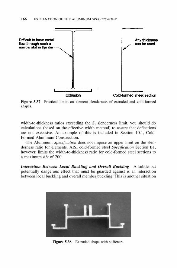
166 EXPLANATION OF THE ALUMINUM SPECIFICATION
Figure 5.37 Practical limits on element slenderness of extruded and cold-formedshapes.
Figure 5.38 Extruded shape with stiffeners.
width-to-thickness ratios exceeding the S2 slenderness limit, you should docalculations (based on the effective width method) to assure that deflectionsare not excessive. An example of this is included in Section 10.1, Cold-Formed Aluminum Construction.
The Aluminum Specification does not impose an upper limit on the slen-derness ratio for elements. AISI cold-formed steel Specification Section B1,however, limits the width-to-thickness ratio for cold-formed steel sections toa maximum b / t of 200.
Interaction Between Local Buckling and Overall Buckling A subtle butpotentially dangerous effect that must be guarded against is an interactionbetween local buckling and overall member buckling. This is another situation
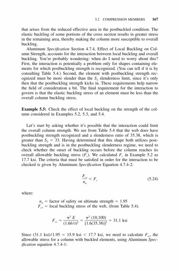
5.2 COMPRESSION MEMBERS 167
that arises from the reduced effective area in the postbuckled condition. Theelastic buckling of some portions of the cross section results in greater stressin the remaining area, thereby making the column more susceptible to overallbuckling.
Aluminum Specification Section 4.7.4, Effect of Local Buckling on Col-umn Strength, accounts for the interaction between local buckling and overallbuckling. You’re probably wondering: when do I need to worry about this?First, the interaction is potentially a problem only for shapes containing ele-ments for which postbuckling strength is recognized. (You can tell if it is byconsulting Table 5.4.) Second, the element with postbuckling strength rec-ognized must be more slender than the S2 slenderness limit, since it’s onlythen that the postbuckling strength kicks in. These requirements help narrowthe field of consideration a bit. The final requirement for the interaction togovern is that the elastic buckling stress of an element must be less than theoverall column buckling stress.
Example 5.5: Check the effect of local buckling on the strength of the col-umn considered in Examples 5.2, 5.3, and 5.4.
Let’s start by asking whether it’s possible that the interaction could limitthe overall column strength. We see from Table 5.4 that the web does havepostbuckling strength recognized and a slenderness ratio of 35.38, which isgreater than S2 � 33. Having determined that this shape both utilizes post-buckling strength and is in the postbuckling slenderness regime, we need tocheck whether the onset of buckling occurs before the column reaches itsoverall allowable buckling stress (Fc). We calculated Fc in Example 5.2 as17.7 ksi. The criteria that must be satisfied in order for the interaction to bechecked is given by Aluminum Specification Equation 4.7.4-2:
Fcr � F (5.24)cnu
where:
nu � factor of safety on ultimate strength � 1.95Fcr � local buckling stress of the web, (from Table 5.4).
2 2� E � (10,100)F � � � 31.1 ksicr 2 2(1.6b / t) [1.6(35.38)]
Since (31.1 ksi) /1.95 � 15.9 ksi � 17.7 ksi, we need to calculate Frc, theallowable stress for a column with buckled elements, using Aluminum Spec-ification equation 4.7.4-1:
168 EXPLANATION OF THE ALUMINUM SPECIFICATION
1 / 3 2 / 3(F ) (F )ec crF �rc nu
2 2� E � (10,100)F � � � 249 ksiwhere: ec 2 2(kL /r) 20
So:
1 / 3 2 / 3(249) (31.1)F � � 31.9 ksirc 1.95
Since Frc � 31.9 ksi � 17.7 ksi � Fc, the interaction does not govern andthe overall column allowable compressive stress is 17.7 ksi. We can nowcompare the overall allowable stress (17.7 ksi) to the allowable stress of theelements (by the weighted average method used in Example 5.4, 16.7 ksi)and use the lesser of these (16.7 ksi) as the allowable stress for the column.
Stiffeners In Table 5.3, we listed Aluminum Specification Sections 3.4.9.1and 3.4.9.2 that deal with stiffeners. You can just plug and chug on theseprovisions with no further thought if you prefer. If you’re curious about howthey work, the next two paragraphs are for you.
Specification Section 3.4.9.1 addresses flat plates with one edge supportedand the other with a stiffener (Figure 5.23c). The allowable compressive stressFc is the lesser of:
FcyF � and F � F � (F � F )c c UT ST UT STny
where:
Fcy � compressive yield strengthFUT � allowable stress for the element calculated according to Specifica-
tion Section 3.4.8 as if no stiffener were presentFST � allowable stress for the element calculated according to Specifica-
tion Section 3.4.9 as if the element were supported along both lon-gitudinal edges
ST � ratio dependent on the radius of gyration of the stiffener and theslenderness ratio of the element stiffened, determined as:
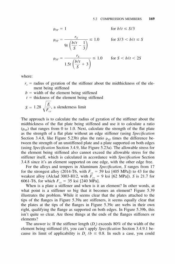
5.2 COMPRESSION MEMBERS 169
� 1 for b / t � S /3ST
rS � � 1.0 for S /3 � b / t � SST b / t 19t �� �S 3
rS � � 1.0 for S � b / t � 2SST b / t1.5t � 3� �S
where:
rs � radius of gyration of the stiffener about the midthickness of the ele-ment being stiffened
b � width of the element being stiffenedt � thickness of the element being stiffened
S � 1.28 a slenderness limitE
,�Fcy
The approach is to calculate the radius of gyration of the stiffener about themidthickness of the flat plate being stiffened and use it to calculate a ratio(ST) that ranges from 0 to 1.0. Next, calculate the strength of the flat plateas the strength of a flat plate without an edge stiffener (using SpecificationSection 3.4.8, like Figure 5.23b) plus the ratio ST times the difference be-tween the strength of an unstiffened plate and a plate supported on both edges(using Specification Section 3.4.9, like Figure 5.23a). The allowable stress forthe element being stiffened also cannot exceed the allowable stress for thestiffener itself, which is calculated in accordance with Specification Section3.4.8 since it’s an element supported on one edge, with the other edge free.
For the alloys and tempers in Aluminum Specification, S ranges from 17for the strongest alloy (2014-T6, with Fcy � 59 ksi [405 MPa]) to 43 for theweakest alloy (Alclad 3003-H12, with Fcy � 9 ksi [62 MPa]). S is 21.7 for6061-T6, for which Fcy � 35 ksi [240 MPa].
When is a plate a stiffener and when is it an element? In other words, atwhat point is a stiffener so big that it becomes an element? Figure 5.39illustrates the problem. While it seems clear that the plates attached to thetips of the flanges in Figure 5.39a are stiffeners, it seems equally clear thatthe plates at the tips of the flanges in Figure 5.39c are webs in their ownright, qualifying the flange as supported on both edges. In Figure 5.39b, thisisn’t quite so clear. Are those things at the ends of the flanges stiffeners orelements?
The answer is: If the stiffener length (Ds) exceeds 80% of the width of theelement being stiffened (b), you can’t apply Specification Section 3.4.9.1 be-cause its limit of applicability is Ds /b � 0.8. In such a case, you could
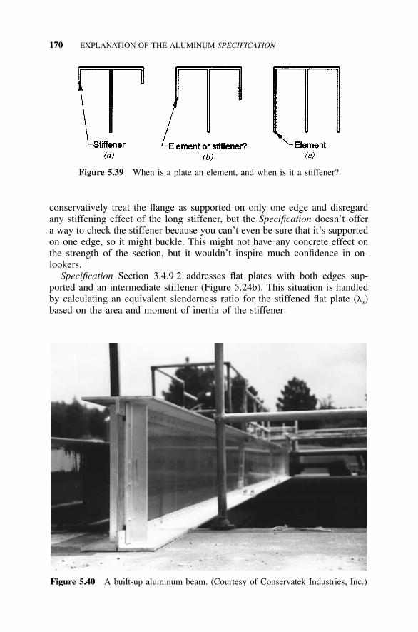
170 EXPLANATION OF THE ALUMINUM SPECIFICATION
Figure 5.39 When is a plate an element, and when is it a stiffener?
Figure 5.40 A built-up aluminum beam. (Courtesy of Conservatek Industries, Inc.)
conservatively treat the flange as supported on only one edge and disregardany stiffening effect of the long stiffener, but the Specification doesn’t offera way to check the stiffener because you can’t even be sure that it’s supportedon one edge, so it might buckle. This might not have any concrete effect onthe strength of the section, but it wouldn’t inspire much confidence in on-lookers.
Specification Section 3.4.9.2 addresses flat plates with both edges sup-ported and an intermediate stiffener (Figure 5.24b). This situation is handledby calculating an equivalent slenderness ratio for the stiffened flat plate (�s)based on the area and moment of inertia of the stiffener:
5.3 MEMBERS IN BENDING 171
1 � A /bts� � 4.62(b / t)s � 31 � �1 � 10.67 I /bto
where:
As � area of the stiffenerIo � moment of inertia of a section composed of the stiffener and one-
half the width of the adjacent plate sub-elements, taken about itsneutral axis
b � one-half of the width of the element being stiffenedt � thickness of the element being stiffened.
Notice that the area of the stiffener is defined differently in the determinationof Io than it is in calculating As and that b is half the width of the elementbeing stiffened, the distance from the stiffener to a supported edge. Also, asthe area of the stiffener approaches zero, Io approaches bt3 /12, which resultsin �s � 3.0b / t. This is reassuring since the slenderness of an element with awidth 2b and supported on both edges is 2(1.6b/t) � 3.2b/t.
A Final Observation If only one thing stands out from this section, it shouldbe that while columns cannot support additional load once they experienceoverall buckling, they can have additional strength after elements of theircross section have undergone local buckling. The reason is that elements aresupported along at least one edge by virtue of their being a part of a section,and this support remains even when a portion of the element buckles. Takingadvantage of the postbuckling strength of elements requires designers to ex-pend considerable additional effort, but it can yield the reward of higherdesign strengths.
5.3 MEMBERS IN BENDING
Just as the term column was used as shorthand for any member in axialcompression, beam is the term used as an abbreviation for a member in bend-ing. Used in this sense, a beam need not necessarily be a horizontal memberbetween columns in a building frame; it can be any member subjected toloads acting transverse to its longitudinal axis.
Bending is associated with three different types of stress in a beam: tensionon one side of the neutral axis, compression on the other, and shear. Sincewe’ve already discussed axial tension and compression in previous sections,we’ve already established some understanding of how aluminum beams aredesigned. So armed, let’s tackle each of these stresses as they act on beams.
5.3.1 Bending Yielding and Fracture
The limit states for bending tension are the same as those for axial tension:fracture and yielding. In other words, we don’t want the beam to break or
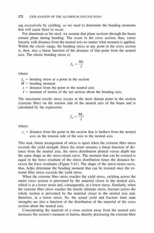
172 EXPLANATION OF THE ALUMINUM SPECIFICATION
sag excessively by yielding, so we need to determine the bending momentsthat will cause these to occur.
For aluminum as for steel, we assume that plane sections through the beamremain plane during bending. The strain in the cross section, thus, varieslinearly with distance from the neutral axis no matter what moment is applied.Within the elastic range, the bending stress at any point in the cross sectionis, then, also a linear function of the distance of that point from the neutralaxis. The elastic bending stress is:
Mxƒ �b I
where:
ƒb � bending stress at a point in the sectionM � bending momentx � distance from the point to the neutral axisI � moment of inertia of the net section about the bending axis.
The maximum tensile stress occurs at the most distant point in the section(extreme fiber) on the tension side of the neutral axis of the beam and iscalculated by the expression:
Mctƒ �b I
where:
ct � distance from the point in the section that is farthest from the neutralaxis on the tension side of the axis to the neutral axis.
This neat, linear arrangement of stress is upset when the extreme fiber stressexceeds the yield strength. Since the strain remains a linear function of dis-tance from the neutral axis, the stress distribution plotted versus depth hasthe same shape as the stress-strain curve. The moment that can be resisted isequal to the force resultant of the stress distribution times the distance be-tween the force resultants (Figure 5.41). The shape of the stress-strain curve,thus, helps determine the bending moment that can be resisted once the ex-treme fiber stress exceeds the yield stress.
When the extreme fiber stress reaches the yield stress, yielding across theentire cross section is prevented by the material closer to the neutral axis,which is at a lower strain and, consequently, at a lower stress. Similarly, whenthe extreme fiber stress reaches the tensile ultimate stress, fracture across thewhole section is prevented by the material closer to the neutral axis and,therefore, at a lower stress. So, the actual yield and fracture limit statestrengths are also a function of the distribution of the material of the crosssection about the neutral axis.
Concentrating the material of a cross section away from the neutral axisincreases the section’s moment of inertia, thereby decreasing the extreme fiber
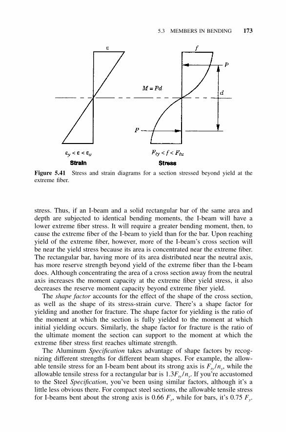
5.3 MEMBERS IN BENDING 173
Figure 5.41 Stress and strain diagrams for a section stressed beyond yield at theextreme fiber.
stress. Thus, if an I-beam and a solid rectangular bar of the same area anddepth are subjected to identical bending moments, the I-beam will have alower extreme fiber stress. It will require a greater bending moment, then, tocause the extreme fiber of the I-beam to yield than for the bar. Upon reachingyield of the extreme fiber, however, more of the I-beam’s cross section willbe near the yield stress because its area is concentrated near the extreme fiber.The rectangular bar, having more of its area distributed near the neutral axis,has more reserve strength beyond yield of the extreme fiber than the I-beamdoes. Although concentrating the area of a cross section away from the neutralaxis increases the moment capacity at the extreme fiber yield stress, it alsodecreases the reserve moment capacity beyond extreme fiber yield.
The shape factor accounts for the effect of the shape of the cross section,as well as the shape of its stress-strain curve. There’s a shape factor foryielding and another for fracture. The shape factor for yielding is the ratio ofthe moment at which the section is fully yielded to the moment at whichinitial yielding occurs. Similarly, the shape factor for fracture is the ratio ofthe ultimate moment the section can support to the moment at which theextreme fiber stress first reaches ultimate strength.
The Aluminum Specification takes advantage of shape factors by recog-nizing different strengths for different beam shapes. For example, the allow-able tensile stress for an I-beam bent about its strong axis is Fty /ny, while theallowable tensile stress for a rectangular bar is 1.3Fty /ny. If you’re accustomedto the Steel Specification, you’ve been using similar factors, although it’s alittle less obvious there. For compact steel sections, the allowable tensile stressfor I-beams bent about the strong axis is 0.66 Fy, while for bars, it’s 0.75 Fy.
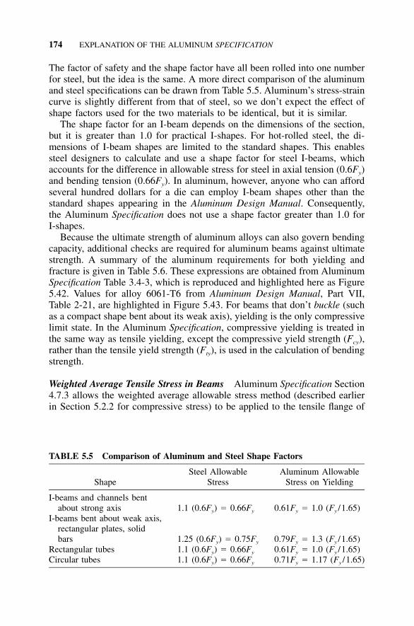
174 EXPLANATION OF THE ALUMINUM SPECIFICATION
TABLE 5.5 Comparison of Aluminum and Steel Shape Factors
ShapeSteel Allowable
StressAluminum Allowable
Stress on Yielding
I-beams and channels bentabout strong axis 1.1 (0.6Fy) � 0.66Fy 0.61Fy � 1.0 (Fy /1.65)
I-beams bent about weak axis,rectangular plates, solidbars 1.25 (0.6Fy) � 0.75Fy 0.79Fy � 1.3 (Fy /1.65)
Rectangular tubes 1.1 (0.6Fy) � 0.66Fy 0.61Fy � 1.0 (Fy /1.65)Circular tubes 1.1 (0.6Fy) � 0.66Fy 0.71Fy � 1.17 (Fy /1.65)
The factor of safety and the shape factor have all been rolled into one numberfor steel, but the idea is the same. A more direct comparison of the aluminumand steel specifications can be drawn from Table 5.5. Aluminum’s stress-straincurve is slightly different from that of steel, so we don’t expect the effect ofshape factors used for the two materials to be identical, but it is similar.
The shape factor for an I-beam depends on the dimensions of the section,but it is greater than 1.0 for practical I-shapes. For hot-rolled steel, the di-mensions of I-beam shapes are limited to the standard shapes. This enablessteel designers to calculate and use a shape factor for steel I-beams, whichaccounts for the difference in allowable stress for steel in axial tension (0.6Fy)and bending tension (0.66Fy). In aluminum, however, anyone who can affordseveral hundred dollars for a die can employ I-beam shapes other than thestandard shapes appearing in the Aluminum Design Manual. Consequently,the Aluminum Specification does not use a shape factor greater than 1.0 forI-shapes.
Because the ultimate strength of aluminum alloys can also govern bendingcapacity, additional checks are required for aluminum beams against ultimatestrength. A summary of the aluminum requirements for both yielding andfracture is given in Table 5.6. These expressions are obtained from AluminumSpecification Table 3.4-3, which is reproduced and highlighted here as Figure5.42. Values for alloy 6061-T6 from Aluminum Design Manual, Part VII,Table 2-21, are highlighted in Figure 5.43. For beams that don’t buckle (suchas a compact shape bent about its weak axis), yielding is the only compressivelimit state. In the Aluminum Specification, compressive yielding is treated inthe same way as tensile yielding, except the compressive yield strength (Fcy),rather than the tensile yield strength (Fty), is used in the calculation of bendingstrength.
Weighted Average Tensile Stress in Beams Aluminum Specification Section4.7.3 allows the weighted average allowable stress method (described earlierin Section 5.2.2 for compressive stress) to be applied to the tensile flange of
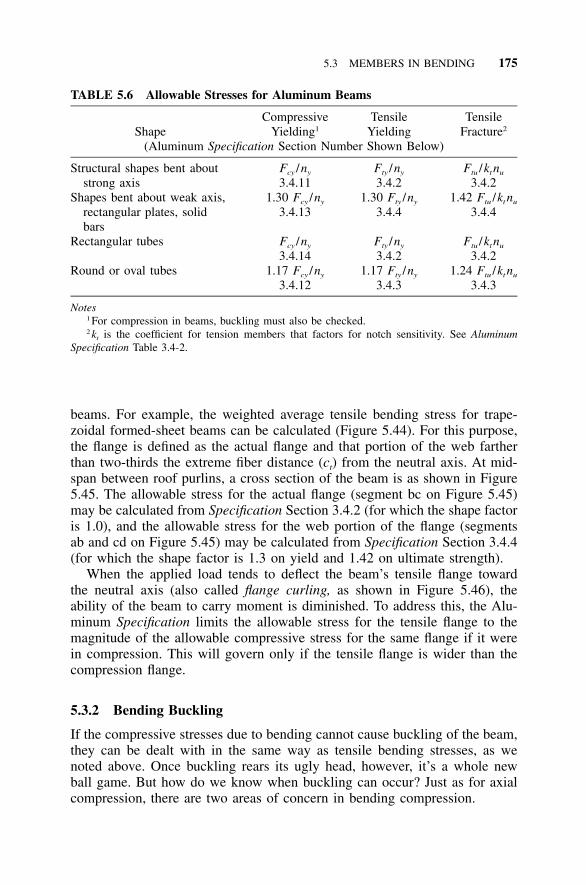
5.3 MEMBERS IN BENDING 175
TABLE 5.6 Allowable Stresses for Aluminum Beams
ShapeCompressive
Yielding1
TensileYielding
TensileFracture2
(Aluminum Specification Section Number Shown Below)
Structural shapes bent aboutstrong axis
Fcy /ny
3.4.11Fty /ny
3.4.2Ftu /kt nu
3.4.2Shapes bent about weak axis,
rectangular plates, solidbars
1.30 Fcy /ny
3.4.131.30 Fty /ny
3.4.41.42 Ftu /kt nu
3.4.4
Rectangular tubes Fcy /ny
3.4.14Fty /ny
3.4.2Ftu /kt nu
3.4.2Round or oval tubes 1.17 Fcy /ny
3.4.121.17 Fty /ny
3.4.31.24 Ftu /kt nu
3.4.3
Notes1 For compression in beams, buckling must also be checked.2 kt is the coefficient for tension members that factors for notch sensitivity. See Aluminum
Specification Table 3.4-2.
beams. For example, the weighted average tensile bending stress for trape-zoidal formed-sheet beams can be calculated (Figure 5.44). For this purpose,the flange is defined as the actual flange and that portion of the web fartherthan two-thirds the extreme fiber distance (ct) from the neutral axis. At mid-span between roof purlins, a cross section of the beam is as shown in Figure5.45. The allowable stress for the actual flange (segment bc on Figure 5.45)may be calculated from Specification Section 3.4.2 (for which the shape factoris 1.0), and the allowable stress for the web portion of the flange (segmentsab and cd on Figure 5.45) may be calculated from Specification Section 3.4.4(for which the shape factor is 1.3 on yield and 1.42 on ultimate strength).
When the applied load tends to deflect the beam’s tensile flange towardthe neutral axis (also called flange curling, as shown in Figure 5.46), theability of the beam to carry moment is diminished. To address this, the Alu-minum Specification limits the allowable stress for the tensile flange to themagnitude of the allowable compressive stress for the same flange if it werein compression. This will govern only if the tensile flange is wider than thecompression flange.
5.3.2 Bending Buckling
If the compressive stresses due to bending cannot cause buckling of the beam,they can be dealt with in the same way as tensile bending stresses, as wenoted above. Once buckling rears its ugly head, however, it’s a whole newball game. But how do we know when buckling can occur? Just as for axialcompression, there are two areas of concern in bending compression.
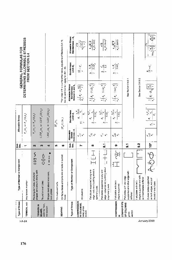
176
5.42
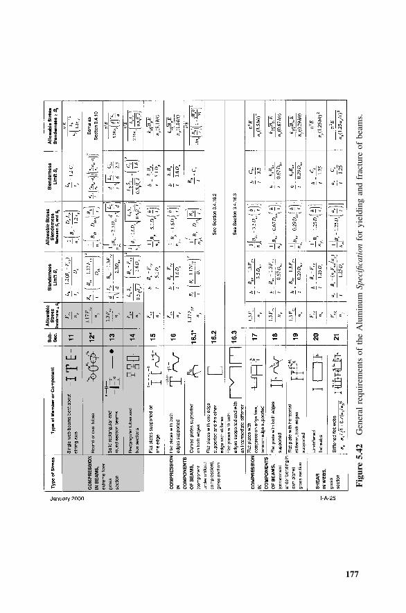
177
Fig
ure
5.42
Gen
eral
requ
irem
ents
ofth
eA
lum
inum
Spec
ifica
tion
for
yiel
ding
and
frac
ture
ofbe
ams.
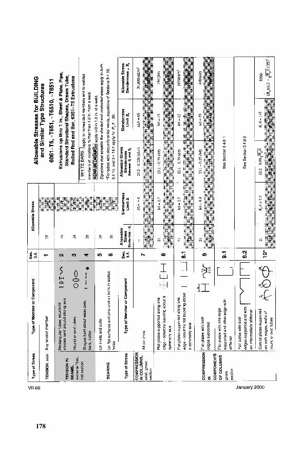
178
Fig
. 5.4
3
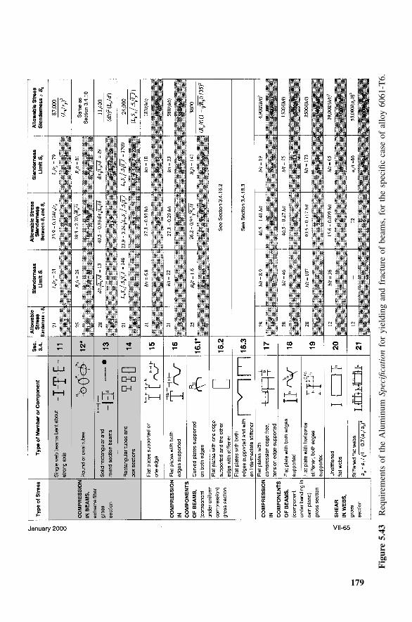
179
Fig
ure
5.43
Req
uire
men
tsof
the
Alu
min
umSp
ecifi
cati
onfo
ryi
eldi
ngan
dfr
actu
reof
beam
s,fo
rth
esp
ecifi
cca
seof
allo
y60
61-T
6.
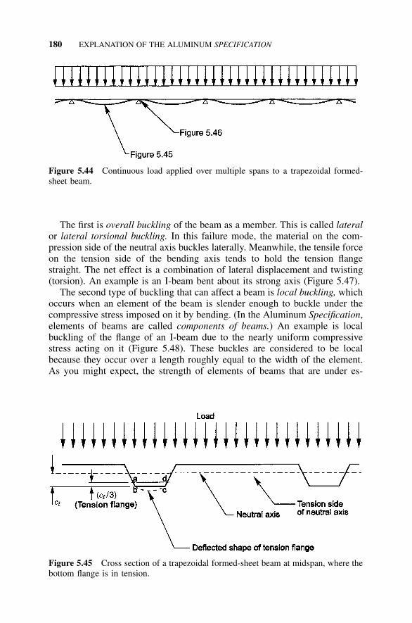
180 EXPLANATION OF THE ALUMINUM SPECIFICATION
Figure 5.44 Continuous load applied over multiple spans to a trapezoidal formed-sheet beam.
Figure 5.45 Cross section of a trapezoidal formed-sheet beam at midspan, where thebottom flange is in tension.
The first is overall buckling of the beam as a member. This is called lateralor lateral torsional buckling. In this failure mode, the material on the com-pression side of the neutral axis buckles laterally. Meanwhile, the tensile forceon the tension side of the bending axis tends to hold the tension flangestraight. The net effect is a combination of lateral displacement and twisting(torsion). An example is an I-beam bent about its strong axis (Figure 5.47).
The second type of buckling that can affect a beam is local buckling, whichoccurs when an element of the beam is slender enough to buckle under thecompressive stress imposed on it by bending. (In the Aluminum Specification,elements of beams are called components of beams.) An example is localbuckling of the flange of an I-beam due to the nearly uniform compressivestress acting on it (Figure 5.48). These buckles are considered to be localbecause they occur over a length roughly equal to the width of the element.As you might expect, the strength of elements of beams that are under es-
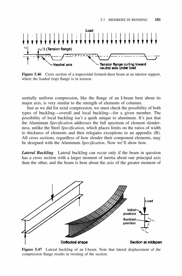
5.3 MEMBERS IN BENDING 181
Figure 5.46 Cross section of a trapezoidal formed-sheet beam at an interior support,where the loaded (top) flange is in tension.
Figure 5.47 Lateral buckling of an I-beam. Note that lateral displacement of thecompression flange results in twisting of the section.
sentially uniform compression, like the flange of an I-beam bent about itsmajor axis, is very similar to the strength of elements of columns.
Just as we did for axial compression, we must check the possibility of bothtypes of buckling—overall and local buckling—for a given member. Thepossibility of local buckling isn’t a quirk unique to aluminum. It’s just thatthe Aluminum Specification addresses the full spectrum of element slender-ness, unlike the Steel Specification, which places limits on the ratios of widthto thickness of elements and then relegates exceptions to an appendix (B).All cross sections, regardless of how slender their component elements, maybe designed with the Aluminum Specification. Now we’ll show how.
Lateral Buckling Lateral buckling can occur only if the beam in questionhas a cross section with a larger moment of inertia about one principal axisthan the other, and the beam is bent about the axis of the greater moment of
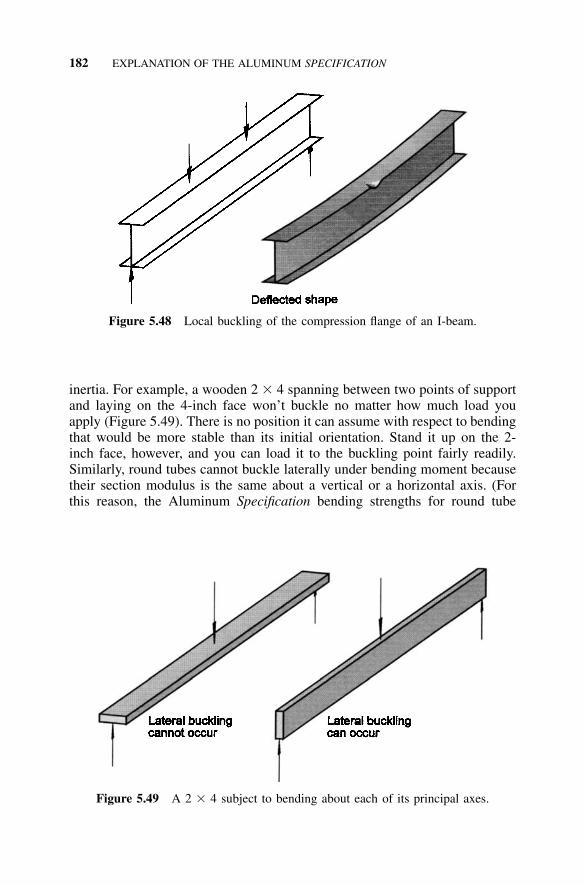
182 EXPLANATION OF THE ALUMINUM SPECIFICATION
Figure 5.48 Local buckling of the compression flange of an I-beam.
Figure 5.49 A 2 � 4 subject to bending about each of its principal axes.
inertia. For example, a wooden 2 � 4 spanning between two points of supportand laying on the 4-inch face won’t buckle no matter how much load youapply (Figure 5.49). There is no position it can assume with respect to bendingthat would be more stable than its initial orientation. Stand it up on the 2-inch face, however, and you can load it to the buckling point fairly readily.Similarly, round tubes cannot buckle laterally under bending moment becausetheir section modulus is the same about a vertical or a horizontal axis. (Forthis reason, the Aluminum Specification bending strengths for round tube
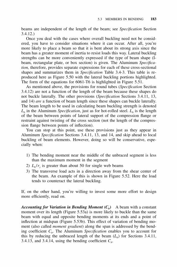
5.3 MEMBERS IN BENDING 183
beams are independent of the length of the beam; see Specification Section3.4.12.)
Once you deal with the cases where overall buckling need not be consid-ered, you have to consider situations where it can occur. After all, you’remore likely to place a beam so that it is bent about its strong axis since thebeam has a greater moment of inertia to resist loads this way. Lateral bucklingstrengths can be more conveniently expressed if the type of beam shape (I-beam, rectangular plate, or box section) is given. The Aluminum Specifica-tion, therefore, provides separate expressions for each of these cross-sectionalshapes and summarizes them in Specification Table 3.4-3. This table is re-produced here as Figure 5.50 with the lateral buckling portions highlighted.The form of the equations for 6061-T6 is highlighted in Figure 5.51.
As mentioned above, the provisions for round tubes (Specification Section3.4.12) are not a function of the length of the beam because these shapes donot buckle laterally. The other provisions (Specification Sections 3.4.11, 13,and 14) are a function of beam length since these shapes can buckle laterally.The beam length to be used in calculating beam buckling strength is denotedLb in the Aluminum Specification, just as for hot-rolled steel. Lb is the lengthof the beam between points of lateral support of the compression flange orrestraint against twisting of the cross section (not the length of the compres-sion flange between points of inflection).
You can stop at this point, use these provisions just as they appear inAluminum Specification Sections 3.4.11, 13, and 14, and skip ahead to localbuckling of beam elements. However, doing so will be conservative, espe-cially when:
1) The bending moment near the middle of the unbraced segment is lessthan the maximum moment in the segment
2) Lb /ry is greater than about 50 for single web beams3) The transverse load acts in a direction away from the shear center of
the beam. An example of this is shown in Figure 5.52. Here the loadtends to counteract the lateral buckling.
If, on the other hand, you’re willing to invest some more effort to designmore efficiently, read on.
Accounting for Variation in Bending Moment (Cb) A beam with a constantmoment over its length (Figure 5.53a) is more likely to buckle than the samebeam with equal and opposite bending moments at its ends and a point ofinflection at midspan (Figure 5.53b). This effect of variation of bending mo-ment (also called moment gradient) along the span is addressed by the bend-ing coefficient Cb. The Aluminum Specification enables you to account forthis by reducing the unbraced length of the beam (Lb) for Sections 3.4.11,3.4.13, and 3.4.14, using the bending coefficient Cb.
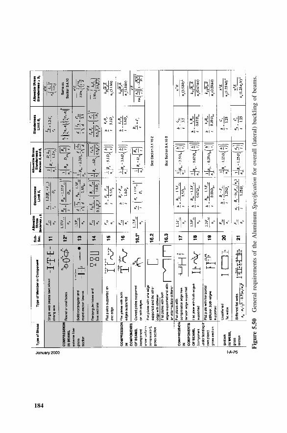
184
Fig
ure
5.50
Gen
eral
requ
irem
ents
ofth
eA
lum
inum
Spec
ifica
tion
for
over
all
(lat
eral
)bu
cklin
gof
beam
s.
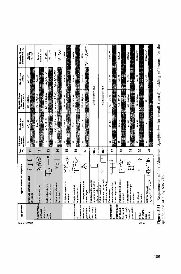
185
Fig
ure
5.51
Req
uire
men
tsof
the
Alu
min
umSp
ecifi
cati
onfo
rov
eral
l(l
ater
al)
buck
ling
ofbe
ams,
for
the
spec
ific
case
ofal
loy
6061
-T6.
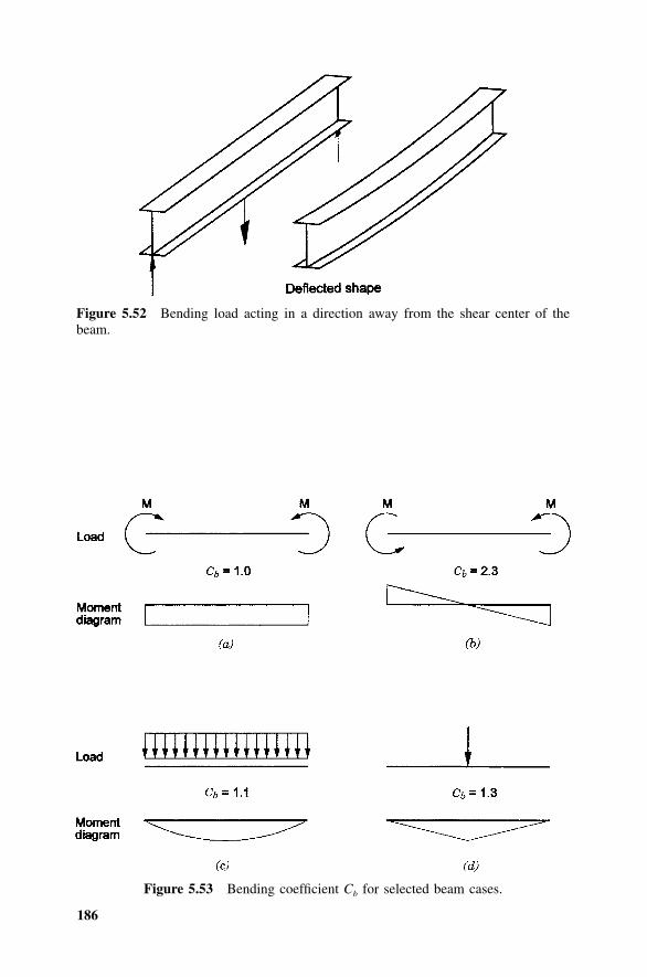
186
Figure 5.52 Bending load acting in a direction away from the shear center of thebeam.
Figure 5.53 Bending coefficient Cb for selected beam cases.
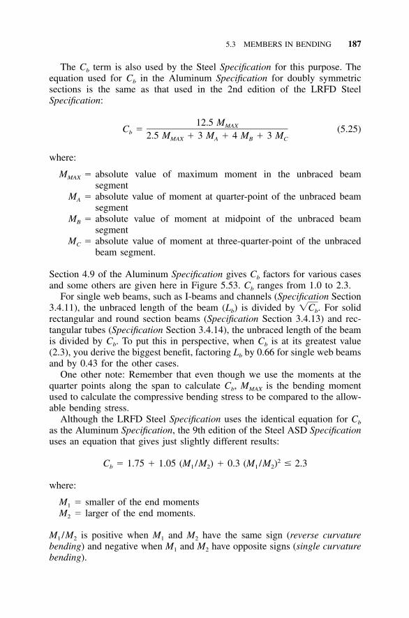
5.3 MEMBERS IN BENDING 187
The Cb term is also used by the Steel Specification for this purpose. Theequation used for Cb in the Aluminum Specification for doubly symmetricsections is the same as that used in the 2nd edition of the LRFD SteelSpecification:
12.5 MMAXC � (5.25)b 2.5 M � 3 M � 4 M � 3 MMAX A B C
where:
MMAX � absolute value of maximum moment in the unbraced beamsegment
MA � absolute value of moment at quarter-point of the unbraced beamsegment
MB � absolute value of moment at midpoint of the unbraced beamsegment
MC � absolute value of moment at three-quarter-point of the unbracedbeam segment.
Section 4.9 of the Aluminum Specification gives Cb factors for various casesand some others are given here in Figure 5.53. Cb ranges from 1.0 to 2.3.
For single web beams, such as I-beams and channels (Specification Section3.4.11), the unbraced length of the beam (Lb) is divided by For solid�C .b
rectangular and round section beams (Specification Section 3.4.13) and rec-tangular tubes (Specification Section 3.4.14), the unbraced length of the beamis divided by Cb. To put this in perspective, when Cb is at its greatest value(2.3), you derive the biggest benefit, factoring Lb by 0.66 for single web beamsand by 0.43 for the other cases.
One other note: Remember that even though we use the moments at thequarter points along the span to calculate Cb, MMAX is the bending momentused to calculate the compressive bending stress to be compared to the allow-able bending stress.
Although the LRFD Steel Specification uses the identical equation for Cb
as the Aluminum Specification, the 9th edition of the Steel ASD Specificationuses an equation that gives just slightly different results:
2C � 1.75 � 1.05 (M /M ) � 0.3 (M /M ) � 2.3b 1 2 1 2
where:
M1 � smaller of the end momentsM2 � larger of the end moments.
M1 /M2 is positive when M1 and M2 have the same sign (reverse curvaturebending) and negative when M1 and M2 have opposite signs (single curvaturebending).
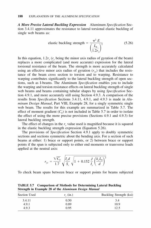
188 EXPLANATION OF THE ALUMINUM SPECIFICATION
TABLE 5.7 Comparison of Methods for Determining Lateral BucklingStrength in Example 28 of the Aluminum Design Manual
Section Used ry (in.) Buckling Strength (ksi)
3.4.11 0.50 3.44.9.1 0.89 10.94.9.3 0.95 12.5
A More Precise Lateral Buckling Expression Aluminum Specification Sec-tion 3.4.11 approximates the resistance to lateral torsional elastic buckling ofsingle web beams as:
2� Eelastic buckling strength � (5.26)2Lb� �1.2ry
In this equation, 1.2ry (ry being the minor axis radius of gyration of the beam)replaces a more complicated (and more accurate) expression for the lateraltorsional resistance of the beam. The strength is more accurately calculatedusing an effective minor axis radius of gyration (rye) that includes the resis-tance of the beam cross section to torsion and to warping. Resistance towarping contributes significantly to the lateral buckling strength of open sec-tions, such as I-beams. The Aluminum Specification enables you to includethe warping and torsion resistance effects on lateral buckling strength of singleweb beams and beams containing tubular shapes by using Specification Sec-tion 4.9.1, and more accurately still using Section 4.9.3. A comparison of theresults from Specification Sections 3.4.11, 4.9.1, and 4.9.3 is made in Alu-minum Design Manual, Part VIII, Example 28, for a singly symmetric singleweb beam. The results for this example are summarized in Table 5.7. Theeffect of moment gradient (Cb) is not included in Table 5.7 in order to isolatethe effect of using the more precise provisions (Sections 4.9.1 and 4.9.3) forlateral buckling strength.
The effect of changes in the ry value used is magnified because it is squaredin the elastic buckling strength expression (Equation 5.26).
The provisions of Specification Section 4.9.1 apply to doubly symmetricsections and sections symmetric about the bending axis. For a section of suchbeams at either: 1) brace or support points, or 2) between brace or supportpoints if the span is subjected only to either end moments or transverse loadsapplied at the neutral axis:
2�C I d k LJb y y br � 1 � 0.152 � �ye ��1.7 S I dc y
To check beam spans between brace or support points for beams subjected
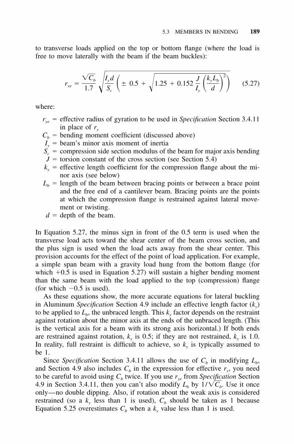
5.3 MEMBERS IN BENDING 189
to transverse loads applied on the top or bottom flange (where the load isfree to move laterally with the beam if the beam buckles):
2�C I d k LJb y y br � � 0.5 � 1.25 � 0.152 (5.27)� � � �ye ��1.7 S I dc y
where:
rye � effective radius of gyration to be used in Specification Section 3.4.11in place of ry
Cb � bending moment coefficient (discussed above)Iy � beam’s minor axis moment of inertiaSc � compression side section modulus of the beam for major axis bendingJ � torsion constant of the cross section (see Section 5.4)
ky � effective length coefficient for the compression flange about the mi-nor axis (see below)
Lb � length of the beam between bracing points or between a brace pointand the free end of a cantilever beam. Bracing points are the pointsat which the compression flange is restrained against lateral move-ment or twisting.
d � depth of the beam.
In Equation 5.27, the minus sign in front of the 0.5 term is used when thetransverse load acts toward the shear center of the beam cross section, andthe plus sign is used when the load acts away from the shear center. Thisprovision accounts for the effect of the point of load application. For example,a simple span beam with a gravity load hung from the bottom flange (forwhich �0.5 is used in Equation 5.27) will sustain a higher bending momentthan the same beam with the load applied to the top (compression) flange(for which �0.5 is used).
As these equations show, the more accurate equations for lateral bucklingin Aluminum Specification Section 4.9 include an effective length factor (ky)to be applied to Lb, the unbraced length. This ky factor depends on the restraintagainst rotation about the minor axis at the ends of the unbraced length. (Thisis the vertical axis for a beam with its strong axis horizontal.) If both endsare restrained against rotation, ky is 0.5; if they are not restrained, ky is 1.0.In reality, full restraint is difficult to achieve, so ky is typically assumed tobe 1.
Since Specification Section 3.4.11 allows the use of Cb in modifying Lb,and Section 4.9 also includes Cb in the expression for effective ry, you needto be careful to avoid using Cb twice. If you use rye from Specification Section4.9 in Section 3.4.11, then you can’t also modify Lb by . Use it once1/�Cb
only—no double dipping. Also, if rotation about the weak axis is consideredrestrained (so a ky less than 1 is used), Cb should be taken as 1 becauseEquation 5.25 overestimates Cb when a ky value less than 1 is used.
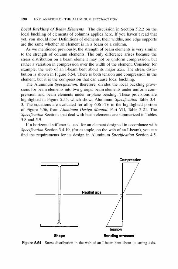
190 EXPLANATION OF THE ALUMINUM SPECIFICATION
Figure 5.54 Stress distribution in the web of an I-beam bent about its strong axis.
Local Buckling of Beam Elements The discussion in Section 5.2.2 on thelocal buckling of elements of columns applies here. If you haven’t read thatyet, you should now. Definitions of elements, their widths, and edge supportsare the same whether an element is in a beam or a column.
As we mentioned previously, the strength of beam elements is very similarto the strength of column elements. The only difference arises because thestress distribution on a beam element may not be uniform compression, butrather a variation in compression over the width of the element. Consider, forexample, the web of an I-beam bent about its major axis. The stress distri-bution is shown in Figure 5.54. There is both tension and compression in theelement, but it is the compression that can cause local buckling.
The Aluminum Specification, therefore, divides the local buckling provi-sions for beam elements into two groups: beam elements under uniform com-pression, and beam elements under in-plane bending. These provisions arehighlighted in Figure 5.55, which shows Aluminum Specification Table 3.4-3. The equations are evaluated for alloy 6061-T6 in the highlighted portionof Figure 5.56, from Aluminum Design Manual, Part VII, Table 2-21. TheSpecification Sections that deal with beam elements are summarized in Tables5.8 and 5.9.
If a horizontal stiffener is used for an element designed in accordance withSpecification Section 3.4.19, (for example, on the web of an I-beam), you canfind the requirements for its design in Aluminum Specification Section 4.5.
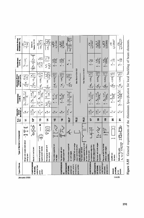
191
Fig
ure
5.55
Gen
eral
requ
irem
ents
ofth
eA
lum
inum
Spec
ifica
tion
for
loca
lbu
cklin
gof
beam
elem
ents
.
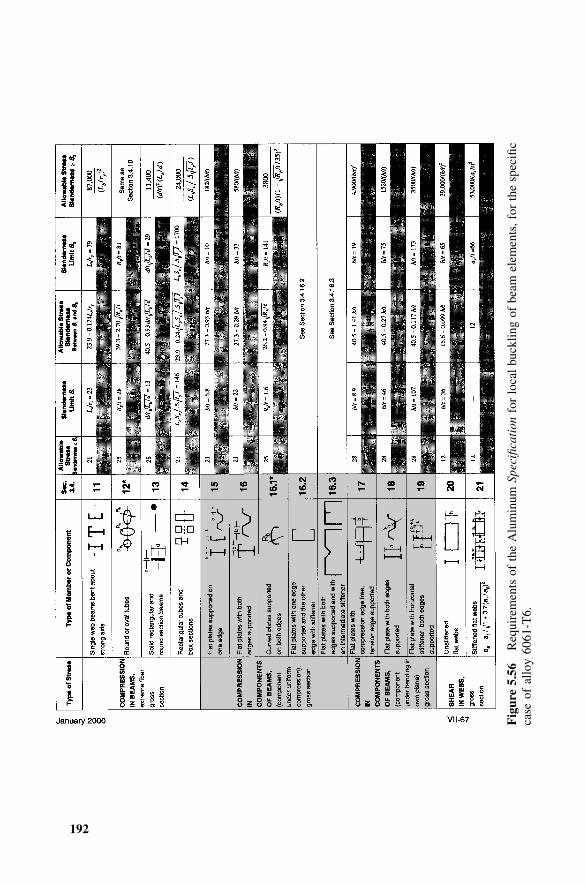
192
Fig
ure
5.56
Req
uire
men
tsof
the
Alu
min
umSp
ecifi
cati
onfo
rlo
cal
buck
ling
ofbe
amel
emen
ts,f
orth
esp
ecifi
cca
seof
allo
y60
61-T
6.
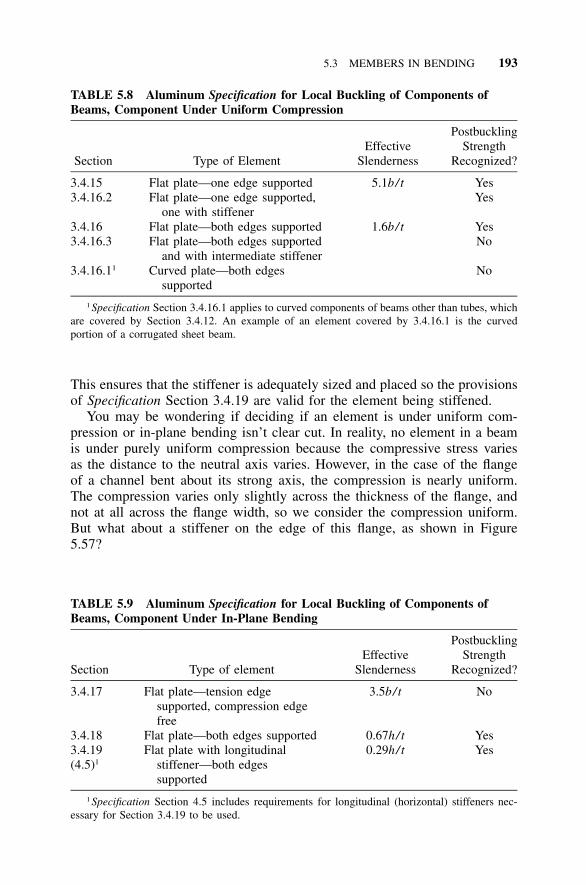
5.3 MEMBERS IN BENDING 193
TABLE 5.8 Aluminum Specification for Local Buckling of Components ofBeams, Component Under Uniform Compression
Section Type of ElementEffective
Slenderness
PostbucklingStrength
Recognized?
3.4.15 Flat plate—one edge supported 5.1b/ t Yes3.4.16.2 Flat plate—one edge supported,
one with stiffenerYes
3.4.16 Flat plate—both edges supported 1.6b/ t Yes3.4.16.3 Flat plate—both edges supported
and with intermediate stiffenerNo
3.4.16.11 Curved plate—both edgessupported
No
1 Specification Section 3.4.16.1 applies to curved components of beams other than tubes, whichare covered by Section 3.4.12. An example of an element covered by 3.4.16.1 is the curvedportion of a corrugated sheet beam.
TABLE 5.9 Aluminum Specification for Local Buckling of Components ofBeams, Component Under In-Plane Bending
Section Type of elementEffective
Slenderness
PostbucklingStrength
Recognized?
3.4.17 Flat plate—tension edgesupported, compression edgefree
3.5b/ t No
3.4.18 Flat plate—both edges supported 0.67h/ t Yes3.4.19(4.5)1
Flat plate with longitudinalstiffener—both edgessupported
0.29h/ t Yes
1 Specification Section 4.5 includes requirements for longitudinal (horizontal) stiffeners nec-essary for Section 3.4.19 to be used.
This ensures that the stiffener is adequately sized and placed so the provisionsof Specification Section 3.4.19 are valid for the element being stiffened.
You may be wondering if deciding if an element is under uniform com-pression or in-plane bending isn’t clear cut. In reality, no element in a beamis under purely uniform compression because the compressive stress variesas the distance to the neutral axis varies. However, in the case of the flangeof a channel bent about its strong axis, the compression is nearly uniform.The compression varies only slightly across the thickness of the flange, andnot at all across the flange width, so we consider the compression uniform.But what about a stiffener on the edge of this flange, as shown in Figure5.57?
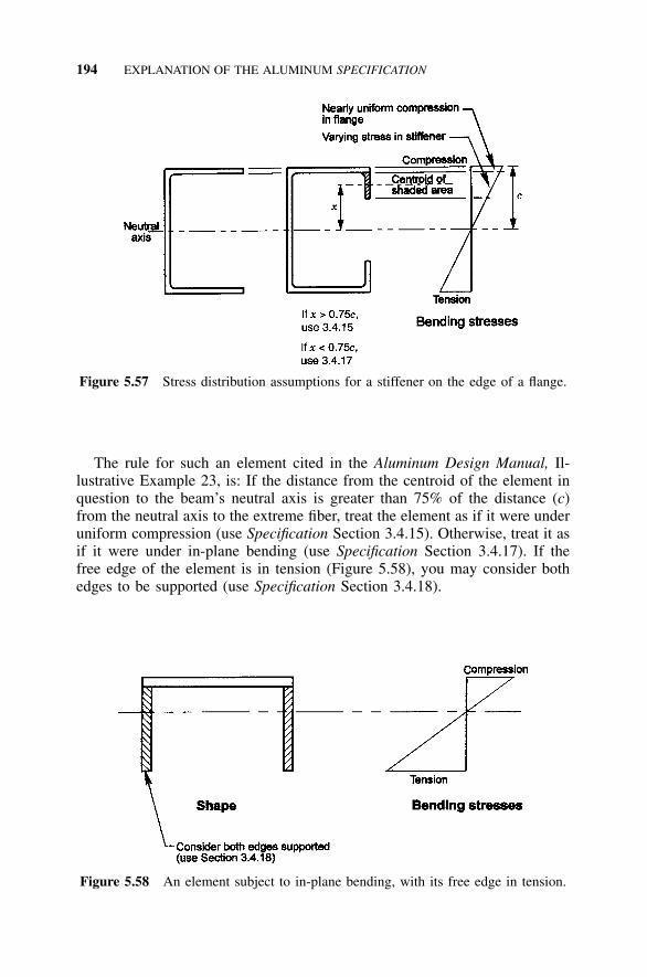
194 EXPLANATION OF THE ALUMINUM SPECIFICATION
Figure 5.57 Stress distribution assumptions for a stiffener on the edge of a flange.
Figure 5.58 An element subject to in-plane bending, with its free edge in tension.
The rule for such an element cited in the Aluminum Design Manual, Il-lustrative Example 23, is: If the distance from the centroid of the element inquestion to the beam’s neutral axis is greater than 75% of the distance (c)from the neutral axis to the extreme fiber, treat the element as if it were underuniform compression (use Specification Section 3.4.15). Otherwise, treat it asif it were under in-plane bending (use Specification Section 3.4.17). If thefree edge of the element is in tension (Figure 5.58), you may consider bothedges to be supported (use Specification Section 3.4.18).
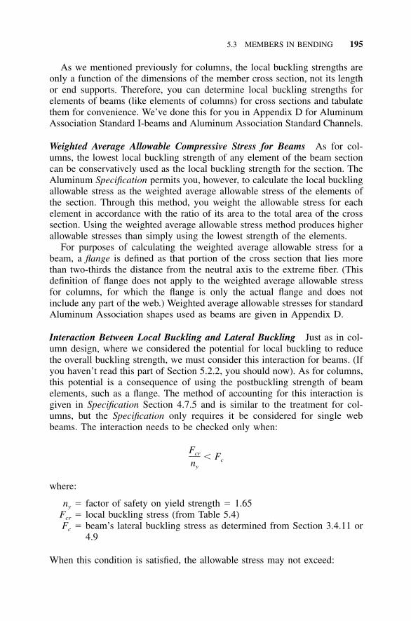
5.3 MEMBERS IN BENDING 195
As we mentioned previously for columns, the local buckling strengths areonly a function of the dimensions of the member cross section, not its lengthor end supports. Therefore, you can determine local buckling strengths forelements of beams (like elements of columns) for cross sections and tabulatethem for convenience. We’ve done this for you in Appendix D for AluminumAssociation Standard I-beams and Aluminum Association Standard Channels.
Weighted Average Allowable Compressive Stress for Beams As for col-umns, the lowest local buckling strength of any element of the beam sectioncan be conservatively used as the local buckling strength for the section. TheAluminum Specification permits you, however, to calculate the local bucklingallowable stress as the weighted average allowable stress of the elements ofthe section. Through this method, you weight the allowable stress for eachelement in accordance with the ratio of its area to the total area of the crosssection. Using the weighted average allowable stress method produces higherallowable stresses than simply using the lowest strength of the elements.
For purposes of calculating the weighted average allowable stress for abeam, a flange is defined as that portion of the cross section that lies morethan two-thirds the distance from the neutral axis to the extreme fiber. (Thisdefinition of flange does not apply to the weighted average allowable stressfor columns, for which the flange is only the actual flange and does notinclude any part of the web.) Weighted average allowable stresses for standardAluminum Association shapes used as beams are given in Appendix D.
Interaction Between Local Buckling and Lateral Buckling Just as in col-umn design, where we considered the potential for local buckling to reducethe overall buckling strength, we must consider this interaction for beams. (Ifyou haven’t read this part of Section 5.2.2, you should now). As for columns,this potential is a consequence of using the postbuckling strength of beamelements, such as a flange. The method of accounting for this interaction isgiven in Specification Section 4.7.5 and is similar to the treatment for col-umns, but the Specification only requires it be considered for single webbeams. The interaction needs to be checked only when:
Fcr � Fcny
where:
ny � factor of safety on yield strength � 1.65Fcr � local buckling stress (from Table 5.4)Fc � beam’s lateral buckling stress as determined from Section 3.4.11 or
4.9
When this condition is satisfied, the allowable stress may not exceed:
196 EXPLANATION OF THE ALUMINUM SPECIFICATION
1 / 3 2 / 3(F ) (F )eb crF �rb ny
where:
Feb � elastic lateral buckling stress of the beam, which is:
�Feb
2� E2Lb� �1.2ry
Plastic Design Plastic design is a design method that utilizes members withthe ability to maintain a full plastic moment through large rotations, so thata hinge mechanism can develop, thereby allowing moment redistribution inthe structure. Because the members must be able to undergo large rotationswithout failing by local buckling, they must be compact (that is, composedof stocky elements [flanges and webs]). Also, on the tensile side of the neutralaxis, the members must be able to sustain large rotations without fracturing,so the material must be ductile.
AISC specifications (38, 39) have compactness requirements to ensure this,but the cold-formed steel (40) and aluminum specifications do not. Since cold-formed steel members are typically composed of slender elements made ofsheet, they are generally incapable of developing plastic hinges without localbuckling. Members covered by the Aluminum Specification may be composedof stocky elements (for example, extrusions having webs and flanges that arethick in relation to their width), or slender elements, which is typical of cold-formed aluminum sheet. Therefore, certain types of aluminum members coulddevelop plastic hinges, but the criteria for their proportions have not beenestablished. Clark (109, Section 10-12) suggests slenderness ratio limits forelements of I, channel, tube, and other shapes for plastic bending that wouldpreclude local buckling, but this has not been incorporated into the AluminumSpecification. Eurocode 9 (102) provides criteria for classifying sections ca-pable of forming a plastic hinge in its Annex G.
Web Crippling Web crippling is a local buckling phenomenon that occursat a point of concentrated transverse load on a beam (Figure 5.59). The dif-ference between the local buckling of a flat plate element of a beam, such asthe flange, and local buckling of a web due to web crippling is that webcrippling results from transverse loading along just a short portion of the edgeof the element. The Aluminum Specification gives provisions for web crip-pling in Section 4.7.7. The equations given in Specification Section 4.7.7 aregeneral and may be applied, for example, to sections formed from bent sheetor to extruded I-beams or channels. A common example is an I-beam web ata beam support. For this case (an extrusion with a single web parallel to theapplied transverse load and a fillet at the web-flange juncture [e.g., Figure5.21]), the equation boils down to:
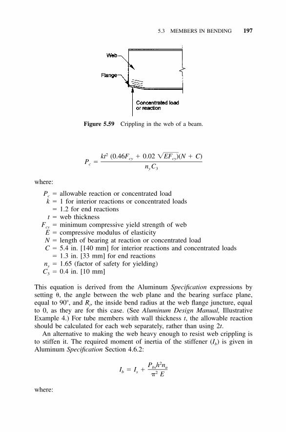
5.3 MEMBERS IN BENDING 197
Figure 5.59 Crippling in the web of a beam.
2kt (0.46F � 0.02 �EF )(N � C)cy cyP �c n Cy 3
where:
Pc � allowable reaction or concentrated loadk � 1 for interior reactions or concentrated loads
� 1.2 for end reactionst � web thickness
Fcy � minimum compressive yield strength of webE � compressive modulus of elasticityN � length of bearing at reaction or concentrated loadC � 5.4 in. [140 mm] for interior reactions and concentrated loads
� 1.3 in. [33 mm] for end reactionsny � 1.65 (factor of safety for yielding)C3 � 0.4 in. [10 mm]
This equation is derived from the Aluminum Specification expressions bysetting �, the angle between the web plane and the bearing surface plane,equal to 90�, and Ri, the inside bend radius at the web flange juncture, equalto 0, as they are for this case. (See Aluminum Design Manual, IllustrativeExample 4.) For tube members with wall thickness t, the allowable reactionshould be calculated for each web separately, rather than using 2t.
An alternative to making the web heavy enough to resist web crippling isto stiffen it. The required moment of inertia of the stiffener (Ib) is given inAluminum Specification Section 4.6.2:
2P h nbs uI � I �b s 2� E
where:
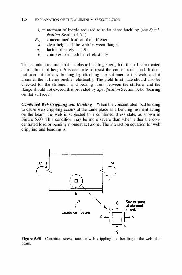
198 EXPLANATION OF THE ALUMINUM SPECIFICATION
Figure 5.60 Combined stress state for web crippling and bending in the web of abeam.
Is � moment of inertia required to resist shear buckling (see Speci-fication Section 4.6.1)
Pbs � concentrated load on the stiffenerh � clear height of the web between flanges
nu � factor of safety � 1.95E � compressive modulus of elasticity
This equation requires that the elastic buckling strength of the stiffener treatedas a column of height h is adequate to resist the concentrated load. It doesnot account for any bracing by attaching the stiffener to the web, and itassumes the stiffener buckles elastically. The yield limit state should also bechecked for the stiffeners, and bearing stress between the stiffener and theflange should not exceed that provided by Specification Section 3.4.6 (bearingon flat surfaces).
Combined Web Crippling and Bending When the concentrated load tendingto cause web crippling occurs at the same place as a bending moment actingon the beam, the web is subjected to a combined stress state, as shown inFigure 5.60. This condition may be more severe than when either the con-centrated load or bending moment act alone. The interaction equation for webcrippling and bending is:
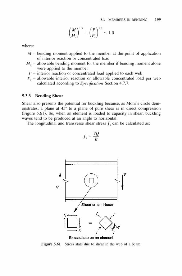
5.3 MEMBERS IN BENDING 199
Figure 5.61 Stress state due to shear in the web of a beam.
1.5 1.5M P� � 1.0� � � �M Pa c
where:
M � bending moment applied to the member at the point of applicationof interior reaction or concentrated load
Ma � allowable bending moment for the member if bending moment alonewere applied to the member
P � interior reaction or concentrated load applied to each webPc � allowable interior reaction or allowable concentrated load per web
calculated according to Specification Section 4.7.7.
5.3.3 Bending Shear
Shear also presents the potential for buckling because, as Mohr’s circle dem-onstrates, a plane at 45� to a plane of pure shear is in direct compression(Figure 5.61). So, when an element is loaded to capacity in shear, bucklingwaves tend to be produced at an angle to horizontal.
The longitudinal and transverse shear stress ƒs can be calculated as:
VQƒ �s It
200 EXPLANATION OF THE ALUMINUM SPECIFICATION
where:
V � shear forceQ � first moment of the cross-sectional area farther from the neutral axis
than the point at which shear stress is calculatedI � moment of inertia of the entire cross-sectional area about the neutral
axist � thickness of the section at the point at which shear stress is calculated.
In an I-beam, shear stresses are small in the flanges, larger in the web, anda maximum at the neutral axis. The maximum shear stress is often approxi-mated as:
Vƒ �s Aw
where:
V � shear forceAw � area of the web � htw
h � clear height of the web with no deductions for web-flange fillets (Fig-ure 5.35)
tw � thickness of the web
Flat Plate Elements in Shear The Aluminum Specification includes twoprovisions for determining allowable shear stress: one for flat plate unstiffenedwebs (Specification Section 3.4.20), and another for flat plate stiffened webs(Specification Section 3.4.21). These are highlighted in Figure 5.62, repro-duced from Aluminum Specification Table 3.4-3. Figure 5.63 is reprinted fromAluminum Design Manual, Part VII, Table 2-21, showing the form of theseequations for alloy 6061-T6. The slenderness ratio of a flat plate web is h/t,where h is the clear height of the web between the flanges with no deductionfor fillets (see Figure 5.35), and t is the thickness of the web.
In order for the web to be considered stiffened so that the provisions ofSpecification Section 3.4.21 can be used, the stiffeners must meet the require-ments of Section 4.6.1, Stiffeners for Web Shear. (These stiffeners aren’tvertical unless the beam is horizontal. They’re more accurately called trans-verse stiffeners in the Steel Specification, Section F4.)
Neither Specification Sections 3.4.20 nor 3.4.21 has postbuckling strengthdirectly included. However, the buckling strength of stiffened webs (3.4.21)indirectly recognizes postbuckling strength by use of a lower factor of safety(1.2 versus 1.65) on the elastic buckling strength. True postbuckling behaviorof webs is also called tension field action, where the beam is considered toact like a truss (Figure 5.64). The buckled portions of the web are disregarded,
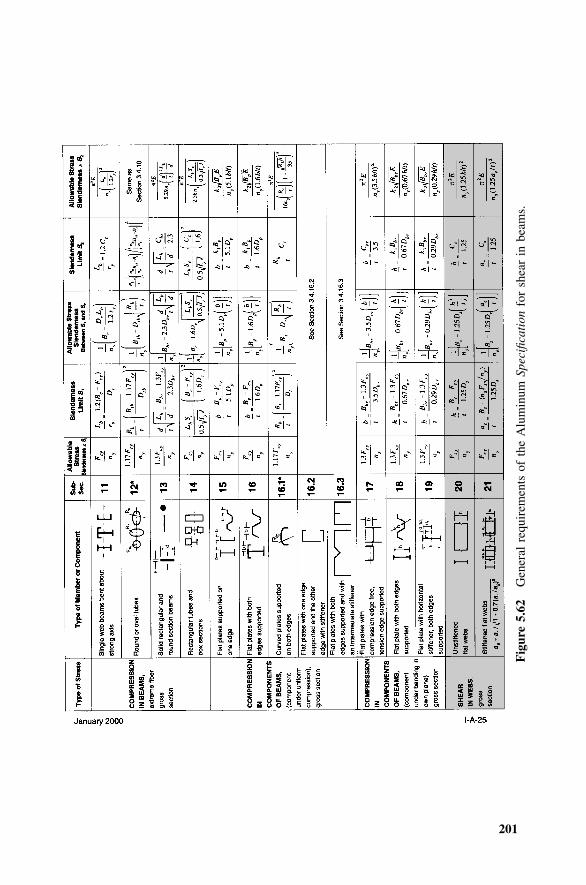
201
Fig
ure
5.62
Gen
eral
requ
irem
ents
ofth
eA
lum
inum
Spec
ifica
tion
for
shea
rin
beam
s.
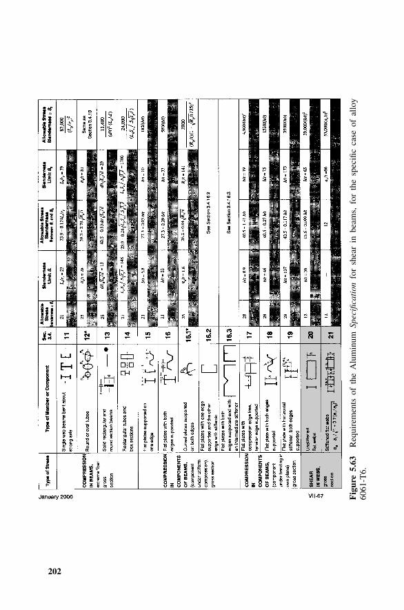
202
Fig
ure
5.63
Req
uire
men
tsof
the
Alu
min
umSp
ecifi
cati
onfo
rsh
ear
inbe
ams,
for
the
spec
ific
case
ofal
loy
6061
-T6.
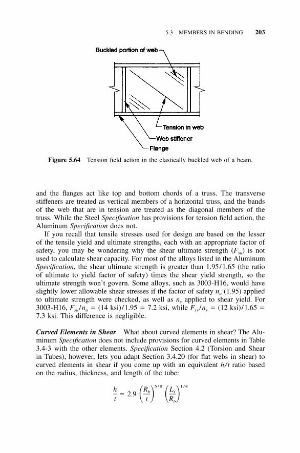
5.3 MEMBERS IN BENDING 203
Figure 5.64 Tension field action in the elastically buckled web of a beam.
and the flanges act like top and bottom chords of a truss. The transversestiffeners are treated as vertical members of a horizontal truss, and the bandsof the web that are in tension are treated as the diagonal members of thetruss. While the Steel Specification has provisions for tension field action, theAluminum Specification does not.
If you recall that tensile stresses used for design are based on the lesserof the tensile yield and ultimate strengths, each with an appropriate factor ofsafety, you may be wondering why the shear ultimate strength (Fsu) is notused to calculate shear capacity. For most of the alloys listed in the AluminumSpecification, the shear ultimate strength is greater than 1.95/1.65 (the ratioof ultimate to yield factor of safety) times the shear yield strength, so theultimate strength won’t govern. Some alloys, such as 3003-H16, would haveslightly lower allowable shear stresses if the factor of safety nu (1.95) appliedto ultimate strength were checked, as well as ny applied to shear yield. For3003-H16, Fsu /nu � (14 ksi) /1.95 � 7.2 ksi, while Fsy /ny � (12 ksi) /1.65 �7.3 ksi. This difference is negligible.
Curved Elements in Shear What about curved elements in shear? The Alu-minum Specification does not include provisions for curved elements in Table3.4-3 with the other elements. Specification Section 4.2 (Torsion and Shearin Tubes), however, lets you adapt Section 3.4.20 (for flat webs in shear) tocurved elements in shear if you come up with an equivalent h/t ratio basedon the radius, thickness, and length of the tube:
5 / 8 1 / 4h R Lb s� 2.9 � � � �t t Rb
204 EXPLANATION OF THE ALUMINUM SPECIFICATION
TABLE 5.10 Shear Stress Provisions in the Aluminum Specification
SpecificationSection Element Description
3.4.20 Flat plate element3.4.21 (4.6.1)1 Flat plate element with transverse stiffener
(Requirements for transverse stiffeners)4.2 Curved element
1 Specification Section 4.6.1 includes requirements for transverse (vertical) stiffeners necessaryfor Section 3.4.21 to be used.
where:
Rb � mid-thickness radius of round tube or maximum mid-thickness radiusof an oval tube
t � tube thicknessLs � length of tube between circumferential stiffeners or overall length if
no circumferential stiffeners are present.
This equation is a simplification that is up to 40% conservative for thin-walledtubes and 20% unconservative for thick-walled tubes. A more precise ap-proach is given in ‘‘Design of Aluminum Tubular Members’’ by Clark andRolf (97).
Table 5.10 is a summary table of bending shear requirements in the Alu-minum Specification.
5.4 TORSION
Torsion occurs in a member when an applied transverse load does not actthrough the cross section’s shear center or when a torque is applied to themember’s longitudinal axis. When the cross section is circular, such as a solidround bar or round tube, or when the member is not restrained from warping,the torsion is called St. Venant torsion, and the torsional stresses are shearstresses only (illustrated by the free end of the cantilever beam; Figure 5.65c).When the member is restrained from warping, such as the fixed end of thecantilever beam in Figure 5.65b, the resulting torsion at the point of warpingrestraint is called warping torsion. The warping stresses are shear (differentfrom the St. Venant shear stresses) and longitudinal stresses (Figure 5.65b).These longitudinal stresses will directly add to bending stresses if the memberis also subjected to major or minor axis bending moments, as AluminumSpecification Section 4.3 reminds us. Along the length of the cantilever beam,both St. Venant and warping torsional stresses are present.
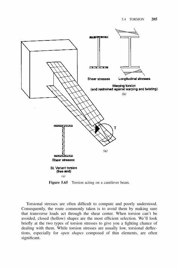
5.4 TORSION 205
Figure 5.65 Torsion acting on a cantilever beam.
Torsional stresses are often difficult to compute and poorly understood.Consequently, the route commonly taken is to avoid them by making surethat transverse loads act through the shear center. When torsion can’t beavoided, closed (hollow) shapes are the most efficient selection. We’ll lookbriefly at the two types of torsion stresses to give you a fighting chance ofdealing with them. While torsion stresses are usually low, torsional deflec-tions, especially for open shapes composed of thin elements, are oftensignificant.
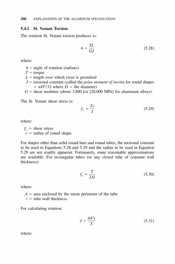
206 EXPLANATION OF THE ALUMINUM SPECIFICATION
5.4.1 St. Venant Torsion
The rotation St. Venant torsion produces is:
TL� � (5.28)
GJ
where:
� � angle of rotation (radians)T � torqueL � length over which twist is permittedJ � torsional constant (called the polar moment of inertia for round shapes
� �D4 /32 where D � the diameter)G � shear modulus (about 3,800 ksi [26,000 MPa] for aluminum alloys).
The St. Venant shear stress is:Tr
ƒ � (5.29)s J
where:
ƒs � shear stressr � radius of round shape.
For shapes other than solid round bars and round tubes, the torsional constantto be used in Equations 5.28 and 5.29 and the radius to be used in Equation5.29 are not readily apparent. Fortunately, some reasonable approximationsare available. For rectangular tubes (or any closed tube of constant wallthickness):
Tƒ � (5.30)s 2At
where:
A � area enclosed by the mean perimeter of the tubet � tube wall thickness.
For calculating rotation:
24A tJ � (5.31)
S
where:
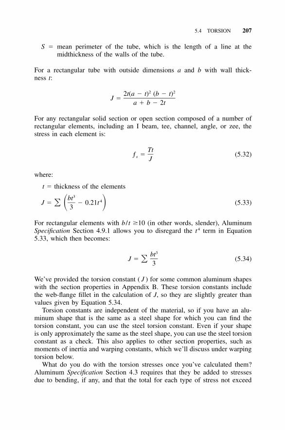
5.4 TORSION 207
S � mean perimeter of the tube, which is the length of a line at themidthickness of the walls of the tube.
For a rectangular tube with outside dimensions a and b with wall thick-ness t:
2 22t(a � t) (b � t)J �
a � b � 2t
For any rectangular solid section or open section composed of a number ofrectangular elements, including an I beam, tee, channel, angle, or zee, thestress in each element is:
Ttƒ � (5.32)s J
where:
t � thickness of the elements3bt 4J � � 0.21t (5.33)� � �3
For rectangular elements with b / t �10 (in other words, slender), AluminumSpecification Section 4.9.1 allows you to disregard the t4 term in Equation5.33, which then becomes:
3btJ � (5.34)�
3
We’ve provided the torsion constant ( J ) for some common aluminum shapeswith the section properties in Appendix B. These torsion constants includethe web-flange fillet in the calculation of J, so they are slightly greater thanvalues given by Equation 5.34.
Torsion constants are independent of the material, so if you have an alu-minum shape that is the same as a steel shape for which you can find thetorsion constant, you can use the steel torsion constant. Even if your shapeis only approximately the same as the steel shape, you can use the steel torsionconstant as a check. This also applies to other section properties, such asmoments of inertia and warping constants, which we’ll discuss under warpingtorsion below.
What do you do with the torsion stresses once you’ve calculated them?Aluminum Specification Section 4.3 requires that they be added to stressesdue to bending, if any, and that the total for each type of stress not exceed
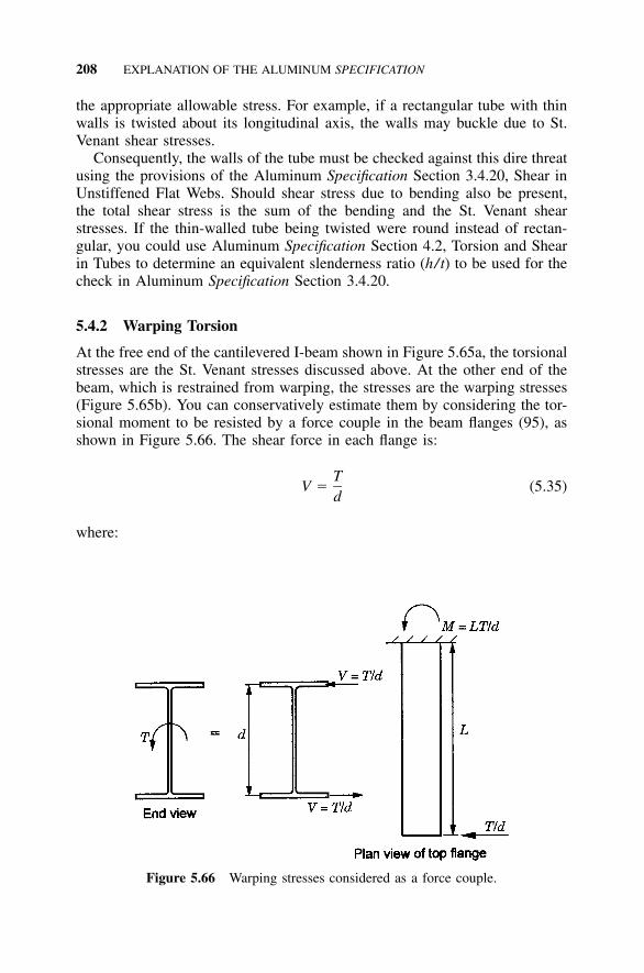
208 EXPLANATION OF THE ALUMINUM SPECIFICATION
Figure 5.66 Warping stresses considered as a force couple.
the appropriate allowable stress. For example, if a rectangular tube with thinwalls is twisted about its longitudinal axis, the walls may buckle due to St.Venant shear stresses.
Consequently, the walls of the tube must be checked against this dire threatusing the provisions of the Aluminum Specification Section 3.4.20, Shear inUnstiffened Flat Webs. Should shear stress due to bending also be present,the total shear stress is the sum of the bending and the St. Venant shearstresses. If the thin-walled tube being twisted were round instead of rectan-gular, you could use Aluminum Specification Section 4.2, Torsion and Shearin Tubes to determine an equivalent slenderness ratio (h/t) to be used for thecheck in Aluminum Specification Section 3.4.20.
5.4.2 Warping Torsion
At the free end of the cantilevered I-beam shown in Figure 5.65a, the torsionalstresses are the St. Venant stresses discussed above. At the other end of thebeam, which is restrained from warping, the stresses are the warping stresses(Figure 5.65b). You can conservatively estimate them by considering the tor-sional moment to be resisted by a force couple in the beam flanges (95), asshown in Figure 5.66. The shear force in each flange is:
TV � (5.35)
d
where:
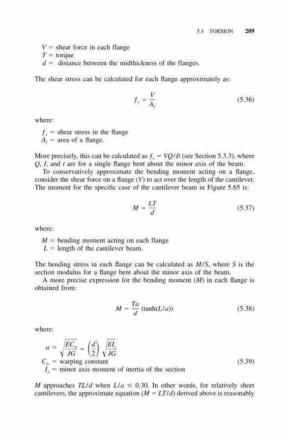
5.4 TORSION 209
V � shear force in each flangeT � torqued � distance between the midthickness of the flanges.
The shear stress can be calculated for each flange approximately as:
Vƒ � (5.36)s Af
where:
ƒs � shear stress in the flangeAf � area of a flange.
More precisely, this can be calculated as ƒs � VQ /It (see Section 5.3.3), whereQ, I, and t are for a single flange bent about the minor axis of the beam.
To conservatively approximate the bending moment acting on a flange,consider the shear force on a flange (V) to act over the length of the cantilever.The moment for the specific case of the cantilever beam in Figure 5.65 is:
LTM � (5.37)
d
where:
M � bending moment acting on each flangeL � length of the cantilever beam.
The bending stress in each flange can be calculated as M/S, where S is thesection modulus for a flange bent about the minor axis of the beam.
A more precise expression for the bending moment (M) in each flange isobtained from:
TaM � (tanh(L /a)) (5.38)
d
where:
a � EC d EIw y� � �� �JG 2 JGCw � warping constant (5.39)Iy � minor axis moment of inertia of the section
M approaches TL /d when L /a � 0.30. In other words, for relatively shortcantilevers, the approximate equation (M � LT /d) derived above is reasonably
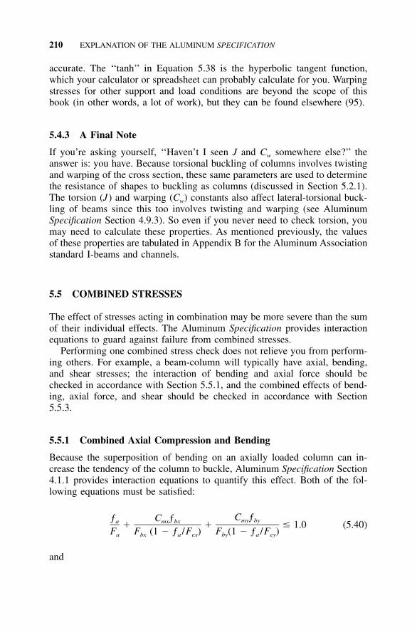
210 EXPLANATION OF THE ALUMINUM SPECIFICATION
accurate. The ‘‘tanh’’ in Equation 5.38 is the hyperbolic tangent function,which your calculator or spreadsheet can probably calculate for you. Warpingstresses for other support and load conditions are beyond the scope of thisbook (in other words, a lot of work), but they can be found elsewhere (95).
5.4.3 A Final Note
If you’re asking yourself, ‘‘Haven’t I seen J and Cw somewhere else?’’ theanswer is: you have. Because torsional buckling of columns involves twistingand warping of the cross section, these same parameters are used to determinethe resistance of shapes to buckling as columns (discussed in Section 5.2.1).The torsion (J) and warping (Cw) constants also affect lateral-torsional buck-ling of beams since this too involves twisting and warping (see AluminumSpecification Section 4.9.3). So even if you never need to check torsion, youmay need to calculate these properties. As mentioned previously, the valuesof these properties are tabulated in Appendix B for the Aluminum Associationstandard I-beams and channels.
5.5 COMBINED STRESSES
The effect of stresses acting in combination may be more severe than the sumof their individual effects. The Aluminum Specification provides interactionequations to guard against failure from combined stresses.
Performing one combined stress check does not relieve you from perform-ing others. For example, a beam-column will typically have axial, bending,and shear stresses; the interaction of bending and axial force should bechecked in accordance with Section 5.5.1, and the combined effects of bend-ing, axial force, and shear should be checked in accordance with Section5.5.3.
5.5.1 Combined Axial Compression and Bending
Because the superposition of bending on an axially loaded column can in-crease the tendency of the column to buckle, Aluminum Specification Section4.1.1 provides interaction equations to quantify this effect. Both of the fol-lowing equations must be satisfied:
C ƒƒ C ƒ my bya mx bx� � � 1.0 (5.40)F F (1 � ƒ /F ) F (1 � ƒ /F )a bx a ex by a ey
and
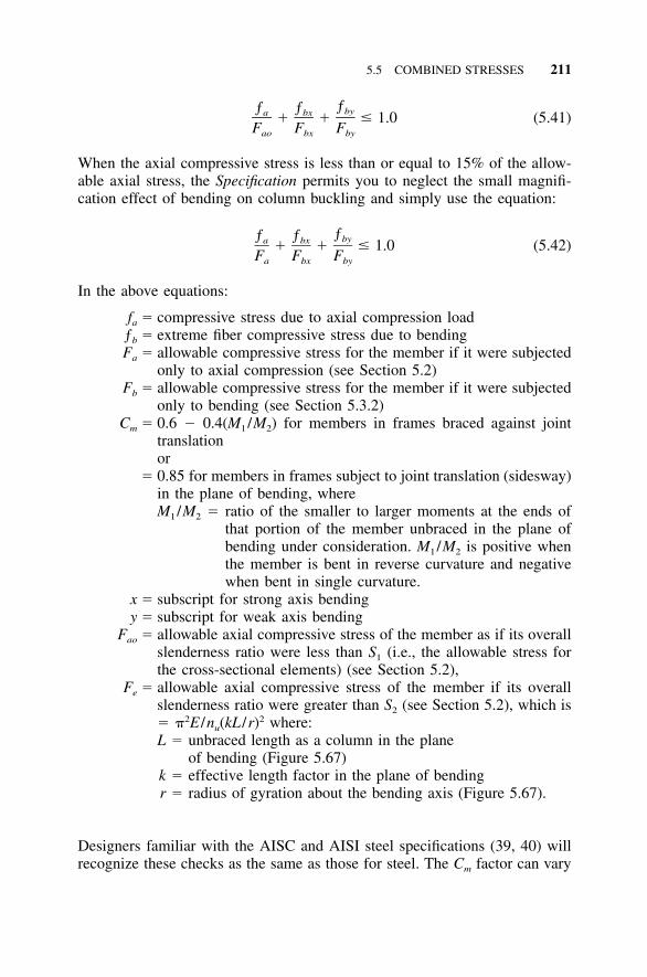
5.5 COMBINED STRESSES 211
ƒƒ ƒ bya bx� � � 1.0 (5.41)F F Fao bx by
When the axial compressive stress is less than or equal to 15% of the allow-able axial stress, the Specification permits you to neglect the small magnifi-cation effect of bending on column buckling and simply use the equation:
ƒƒ ƒ bya bx� � � 1.0 (5.42)F F Fa bx by
In the above equations:
fa � compressive stress due to axial compression loadƒb � extreme fiber compressive stress due to bendingFa � allowable compressive stress for the member if it were subjected
only to axial compression (see Section 5.2)Fb � allowable compressive stress for the member if it were subjected
only to bending (see Section 5.3.2)Cm � 0.6 � 0.4(M1 /M2) for members in frames braced against joint
translationor
� 0.85 for members in frames subject to joint translation (sidesway)in the plane of bending, whereM1 /M2 � ratio of the smaller to larger moments at the ends of
that portion of the member unbraced in the plane ofbending under consideration. M1 /M2 is positive whenthe member is bent in reverse curvature and negativewhen bent in single curvature.
x � subscript for strong axis bendingy � subscript for weak axis bending
Fao � allowable axial compressive stress of the member as if its overallslenderness ratio were less than S1 (i.e., the allowable stress forthe cross-sectional elements) (see Section 5.2),
Fe � allowable axial compressive stress of the member if its overallslenderness ratio were greater than S2 (see Section 5.2), which is� �2E /nu(kL /r)2 where:L � unbraced length as a column in the plane
of bending (Figure 5.67)k � effective length factor in the plane of bendingr � radius of gyration about the bending axis (Figure 5.67).
Designers familiar with the AISC and AISI steel specifications (39, 40) willrecognize these checks as the same as those for steel. The Cm factor can vary
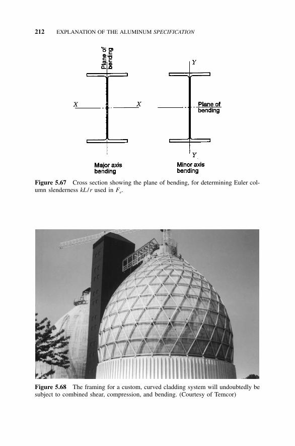
212 EXPLANATION OF THE ALUMINUM SPECIFICATION
Figure 5.67 Cross section showing the plane of bending, for determining Euler col-umn slenderness kL /r used in Fe.
Figure 5.68 The framing for a custom, curved cladding system will undoubtedly besubject to combined shear, compression, and bending. (Courtesy of Temcor)
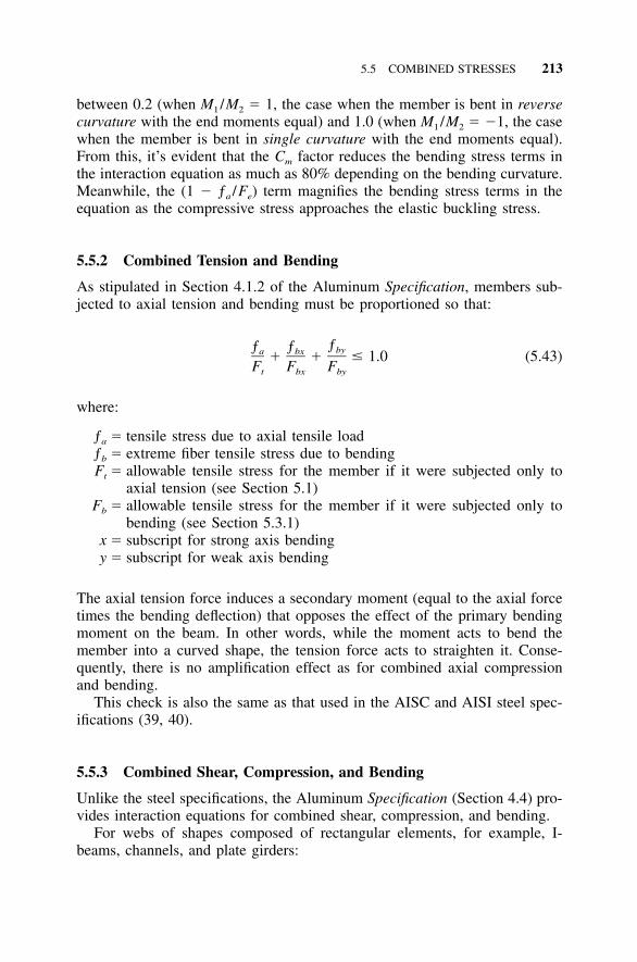
5.5 COMBINED STRESSES 213
between 0.2 (when M1 /M2 � 1, the case when the member is bent in reversecurvature with the end moments equal) and 1.0 (when M1 /M2 � �1, the casewhen the member is bent in single curvature with the end moments equal).From this, it’s evident that the Cm factor reduces the bending stress terms inthe interaction equation as much as 80% depending on the bending curvature.Meanwhile, the (1 � ƒa /Fe) term magnifies the bending stress terms in theequation as the compressive stress approaches the elastic buckling stress.
5.5.2 Combined Tension and Bending
As stipulated in Section 4.1.2 of the Aluminum Specification, members sub-jected to axial tension and bending must be proportioned so that:
ƒƒ ƒ bya bx� � � 1.0 (5.43)F F Ft bx by
where:
ƒa � tensile stress due to axial tensile loadƒb � extreme fiber tensile stress due to bendingFt � allowable tensile stress for the member if it were subjected only to
axial tension (see Section 5.1)Fb � allowable tensile stress for the member if it were subjected only to
bending (see Section 5.3.1)x � subscript for strong axis bendingy � subscript for weak axis bending
The axial tension force induces a secondary moment (equal to the axial forcetimes the bending deflection) that opposes the effect of the primary bendingmoment on the beam. In other words, while the moment acts to bend themember into a curved shape, the tension force acts to straighten it. Conse-quently, there is no amplification effect as for combined axial compressionand bending.
This check is also the same as that used in the AISC and AISI steel spec-ifications (39, 40).
5.5.3 Combined Shear, Compression, and Bending
Unlike the steel specifications, the Aluminum Specification (Section 4.4) pro-vides interaction equations for combined shear, compression, and bending.
For webs of shapes composed of rectangular elements, for example, I-beams, channels, and plate girders:
214 EXPLANATION OF THE ALUMINUM SPECIFICATION
2 2ƒ ƒ ƒa b s� � � 1.0 (5.44)� � � �F F Fa b s
For shapes composed of curved elements, such as round tubes:
2ƒ ƒ ƒa b s� � � 1.0 (5.45)� �F F Fa b s
where:
ƒa � compressive stress due to axial compression loadFa � allowable compressive stress for the member if it were subjected only
to axial compression (see Section 5.2)ƒb � extreme fiber compressive stress due to bendingFb � allowable compressive stress for the member if it were subjected only
to bending (see Section 5.3.2)ƒs � maximum shear stressFs � allowable shear stress for the member if it were subjected only to shear
(see Section 5.3.3).
The combined shear, compression, and bending check will only govern thedesign of members subject to high shear stresses, such as deep beams. Whenno axial compression occurs, Equation 5.44 is the same as the combinedbending and shear interaction equation in the cold-formed steel specification(40). That equation should be used for checking combined bending and sheareven when no axial compression is present. Combined web crippling andshear (see Section 5.3.2) may also need to be checked in this case.
Remember that the interaction equations of Section 5.5.1 (combined axialcompression and bending) must also be satisfied, whether or not shear ispresent.
5.5.4 Biaxial and Triaxial Stresses
The stresses and stress combinations addressed by the Aluminum Specifica-tion and discussed above are generally for longitudinal, uniaxial stress statesin prismatic members such as columns. This is partly because the Specifica-tion predates finite element analysis (FEA) and doesn’t directly address issuesthat arise from such analyses. FEA, on the other hand, can provide triaxialstresses by reporting, in addition to longitudinal stresses, transverse andthrough-thickness stresses. Many FEA programs calculate a von Mises stress(explained below) from the triaxial stresses at a given element. If you’rewondering what to do in situations such as this, read on.
Yielding occurs in ductile materials, such as aluminum, when:
5.5 COMBINED STRESSES 215
2 2 2 2(ƒ � ƒ ) � (ƒ � ƒ ) � (ƒ � ƒ ) � 2 F1 2 2 3 3 1 y
where:
ƒ1, ƒ2, ƒ3 � principal stresses (the normal stress on each of three orthogonalsurfaces such that the shear stresses on the surfaces are zero)
Fy � yield stress
This equation is called the von Mises criterion or distortion energy criterion.It predicts that yielding occurs when the distortion energy equals the distortionenergy in an axially loaded member at yield. The above equation is for thegeneral triaxial stress state. If stresses are biaxial, ƒ3 � 0, and the equationabove predicts yielding when:
2 2 2 2(ƒ � ƒ ) � ƒ � ƒ � 2 F1 2 2 1 ty
The von Mises stress is defined from the von Mises criterion as:
2 2 2(ƒ � ƒ ) � (ƒ � ƒ ) � (ƒ � ƒ )1 2 2 3 3 1Triaxial von Mises stress � � 2
so that it may be compared directly to the yield stress to determine if yieldingoccurs. In the biaxial stress state, the von Mises stress becomes:
2 2Biaxial von Mises stress � �ƒ � ƒ ƒ �ƒ1 1 2 2
The von Mises criterion isn’t just an exotic concept without relevance to theAluminum Specification: it’s used in the Specification to determine the shearyield strength of aluminum alloys, since there is no established test methodto measure shear yield strength. In the case of pure shear, the shear stressesin a biaxial stress element are � and ��. Mohr’s circle can be used to showthat the principal stresses ƒ1 and ƒ2 are, then, also � and ��, so the von Misesstress is:
2 2�� � �(��) � � � � �3
When the von Mises stress equals Fty, yielding occurs, so shear yield �y is:
Fty� �y
�3
This is the relationship used in the Specification’s minimum mechanical prop-erty tables as discussed in Section 4.2 of this book.
216 EXPLANATION OF THE ALUMINUM SPECIFICATION
The von Mises criterion only predicts yielding, and doesn’t address fractureor instability. Furthermore, Roark (140) notes that yielding ‘‘may occur lo-cally in a member and do no real damage if the volume of material affectedis so small or so located as to have only negligible influence on the form andstrength of the member as a whole.’’ So just because the von Mises stress hasbeen exceeded at a given point in the structural component doesn’t mean thepart has reached the limit of its structural usefulness. Also, just because thevon Mises stress hasn’t exceeded the yield strength doesn’t mean the parthasn’t buckled. But yielding causing significant distortion of the part is a limitstate, so knowing when yielding occurs is useful. This can be summarizedas:
Stresses that cause distortion that prevents a member from performing itsintended function shall be limited by:
2 2 2 F(ƒ � ƒ ) � (ƒ � ƒ ) � (ƒ � ƒ ) y1 2 2 3 3 1 �� 2 ny
where:
ƒ1, ƒ2, ƒ3 � principal stressesFy � yield strengthny � safety factor on yield
217
6 Orientation to theAluminum Specification
Aluminum has a much briefer commercial history than steel, with the firstsignificant aluminum production in the U.S. in the 1890s and the first alu-minum structural applications around 1930. As you might expect, the historyof aluminum structural specifications is also shorter than that of steel. Thefirst AISC steel manual was published in 1923; its aluminum counterpart, in1967. This chapter provides the background of U.S. aluminum structural de-sign specifications.
6.1 BACKGROUND
The earliest design rules for aluminum structures were developed at Alcoaaround 1930 and were used to design the aluminum deck and floor beamsinstalled on the Smithfield Street Bridge in Pittsburgh in 1933. In May 1952,the American Society of Civil Engineers (ASCE), which celebrated its cen-tennial that year, published an article titled, ‘‘Specifications for Structures ofa Moderate Strength Aluminum Alloy of High Resistance to Corrosion.’’ Thisspecification, and similar ones that followed in 1956 and 1962 (130), werethe work of the Task Committee on Lightweight Alloys, Committee on Met-als, of the Structural Division of the ASCE. At the same time, each of themajor producers of aluminum, including Alcoa (1), followed by Reynolds andKaiser (both of whom began production in the 1940s), developed structuraldesign handbooks for their products.
The Specifications for Aluminum Structures was first published in 1967 bythe Aluminum Association, the nationally recognized trade organization forthe aluminum industry, based on the ASCE work. The Aluminum Specifica-tions supplanted the design specifications of the ASCE and the various pro-ducers and became part of a five-volume construction-manual series thatincluded:
• Section 1: Specifications for Aluminum Structures• Section 1A: Commentary on Specifications for Aluminum Structures• Section 2: Illustrative Examples of Design
218 ORIENTATION TO THE ALUMINUM SPECIFICATION
• Section 3: Engineering Data for Aluminum Structures• Section 5: Specifications for Aluminum Sheet Metal Work in Building
Construction
Section 3, Engineering Data for Aluminum Structures, contained tables ofsection properties for common aluminum shapes, such as channels, I-beams,angles, and tees, and other useful information for structural design in alu-minum. (Whatever was intended for Section 4 has been lost to the ages.)Taken together, the various sections of the construction manual series werean aluminum equivalent of the AISC Manual of Steel Construction (39).
Unlike the AISC steel specification, the Aluminum Specifications containedtwo sets of safety factors: one set for buildings, and one for bridges. TheAluminum Specifications’ safety factors for buildings were roughly consistentwith the safety factors used for steel buildings—about for yielding and 25–3for ultimate strength. A number of aluminum bridges had been designed andbuilt just before the first publication of the Aluminum Specifications, so pro-visions were made for design of such structures with higher safety factorsthan those for buildings. This, too, was consistent with the philosophy usedfor steel bridge design.
The Aluminum Specifications were revised in 1971, 1976, 1982, and 1986,but most of the provisions remained unchanged. In the fifth edition (1986),fatigue provisions were significantly expanded to define stress categories sim-ilar to those used for steel. A substantial rewrite of the Specifications wasundertaken for the sixth edition (1994). Changes included:
• Postbuckling strength in flat plate elements of sections supported alongone edge was recognized.
• Provisions for edge stiffeners were refined, and new provisions for in-termediate stiffeners were added.
• Sections on lateral buckling of beams and web crippling were improved.• Fatigue strengths were revised based on new data, and provisions were
added to address variable amplitude loads.• Provisions were added for columns subject to torsional or torsional-
flexural buckling, and the effective length factor k was introduced.• Design criteria for self-tapping screws in shear and tension were greatly
expanded.• Yield strengths for longitudinally welded members were revised.• Two types of testing were identified: tests for determining mechanical
properties and tests for determining structural performance, and new pro-cedures for the application of their results were given.
Perhaps even more significantly, the first U.S. aluminum load and resistancefactor design (LRFD) specification was added. (Canada, which publishedStrength Design in Aluminum in 1983, (96) already had one.) The Aluminum
6.2 THE ALUMINUM DESIGN MANUAL 219
Association’s LRFD Specification applies only to building type structures. TheAmerican Association of State Highway and Transportation Officials LRFDBridge Design Specifications governs LRFD for aluminum bridge members;the aluminum section in this specification was developed with the cooperationof the Aluminum Association (35). The LRFD Aluminum Specification isdiscussed in Chapter 11.
The Aluminum Specification was revised again in 2000, including a cos-metic change in the title from the plural to the singular. The significantchanges were:
• 5052-O, 5083-O, 5086-O, 5454-O, 5456-O, 6066-T6, 6070-T6, and6463-T6 were added to the minimum mechanical property tables; 3006-H391, 5083-H323, and 5083-H343 were dropped; and metric versions ofthese tables were added.
• Fatigue provisions for mechanically fastened connections were revised.• Design strengths were increased for yielding compression limit states by
about 10% by eliminating the kc factor.• Yielding on the net section was eliminated as a limit state for tension
members.• Bearing design strengths were substantially increased.• Provisions for slip-critical bolted connections were added.• Block shear design provisions similar to those for hot-rolled steel were
added.• Screw pull-out strengths were revised in light of additional test data.
The Aluminum Specification provisions for member design are explained inChapter 5.
6.2 THE ALUMINUM DESIGN MANUAL
The publishing format of the old construction manual series was changed in1994 to incorporate most of the aluminum construction manual series materialand some new information in the Aluminum Design Manual, which contains:
Part IA—Specification for Aluminum Structures—Allowable Stress Design
Part IB—Specification for Aluminum Structures—Load and Resistance FactorDesign of Buildings and Similar Type Structures See the comments in Sec-tion 6.1 and Chapter 11 regarding LRFD.
Part IIA—Commentary on Specification for Aluminum Structures AllowableStress Design The commentary provides background information and citesreferences for provisions in the allowable stress design Specification (Part IA).
220 ORIENTATION TO THE ALUMINUM SPECIFICATION
This information (except for discussion of safety factors) also applies to theLRFD Specification (Part IB).
Part IIB—Commentary on Specification for Aluminum Structures Load andResistance Factor Design This commentary documents the resistance factorsin the LRFD Specification (Part IB).
Part III—Design Guide This part gives general information on the designof aluminum structural members that may be useful in any industry, not justbuilding or bridge construction. The intent is to provide designers of alumi-num transportation structures, for example, rail cars, with information aboutthe strength of aluminum structural components. Users may then apply what-ever factors of safety are appropriate to the application, which may be dif-ferent from those used for buildings or bridges.
Part IV—Materials General information on aluminum alloys is given here,including tables of comparative characteristics and typical applications.
Part V—Material Properties Minimum and typical mechanical propertiesare given for a number of commonly used aluminum alloys in this part. Allof the provisions of the Aluminum Specification are based on using minimummechanical properties. For structural design, consider typical properties to befor general information and amusement only! Also, don’t despair if the alloyyou need isn’t listed in this section: some minimum mechanical propertiesfor other aluminum alloys can be found in the Aluminum Association pub-lication Aluminum Standards and Data. See also Chapter 4 of this book,‘‘Material Properties for Design,’’ for more information.
Part VI—Section Properties Section properties, such as area, moments ofinertia, and section moduli are given for various aluminum shapes. A rela-tively new feature is the introduction of a designation system for aluminumshapes; this system hasn’t caught on yet commercially. While all of the shapeslisted here are theoretically possible to produce in aluminum, not all areavailable. For example, the 12 in. � 20 in. rectangular tube shown is notlisted in any extruder’s current catalog, and would be difficult and expensiveto manufacture. Such shapes were included under the if-you’ve-got-the-money-we’ve-got-the-time theory. Consequently, users would be well advisedto check the availability of a particular section with suppliers before investingtoo much time on design.
This part also gives formulas for calculating section properties, as well assome information useful in determining dimensions of parts fabricated bybending.
6.2 THE ALUMINUM DESIGN MANUAL 221
Part VII—Design Aids This section contains:
• graphs of allowable stresses• buckling constants for the alloys and tempers included in the Aluminum
Specification• allowable stress tables for common aluminum alloys and some allowable
load tables• beam formulas
The allowable stress tables (Tables 2-2 through 2-23) are extremely usefulbecause they can spare you a lot of number crunching. You should, however,heed some warnings when using them. Many of the tables are groupings ofseveral alloys, such as 6061-T6 and 6351-T5, or product forms, such as ex-trusions and plate. When this is done, the tables use the lowest minimumstrengths of any alloy or product form in the grouping to determine allowablestresses. Consequently, the tables give lower allowable stresses for some al-loys than would be calculated from the direct application of the specificationprovisions. For example, Table 2-21 lists the allowable axial tensile stress for6061-T6 extrusions and plate both as 19 ksi (Specification Section 3.4.1).This is based on the strengths for extrusions, which are less than those ofplate, and are:
F � 35 ksi and F � 38 ksity tu
from which the allowable axial tensile stress is calculated as the lesser of:
F � (35 ksi) /1.65 � 21.2 ksi and
F � (38 ksi) /1.95 � 19.5 ksi
which is rounded to 19 ksi in the table. However, the strength of 6061-T6sheet and plate 0.01 in. through 4.00 in. thick is:
F � 35 ksi and F � 42 ksity tu
from which the allowable axial tensile stress is calculated as the lesser of:
F � (35 ksi) /1.65 � 21.2 ksi and
F � (42 ksi) /1.95 � 21.5 ksi.
The allowable stress for the plate is, therefore, 21.2 ksi, which is about 12%(� 21.2/19) higher than the value given in the table. This example showshow the tables are conservative; they may be too conservative for your taste.
222 ORIENTATION TO THE ALUMINUM SPECIFICATION
If so, you can calculate the allowable stresses for your particular case. SeeChapter 5 for help.
You should note one other item in the Aluminum Design Manual allowablestress tables for the various alloys in Part VII. Slenderness limits S1 and S2
in the tables differ from the values that are calculated for S1 and S2 using theexpressions in the Aluminum Specification. For example, for 1100-H14, inTable 2-2 Section 3.4.11 (beams), S1 as calculated from the buckling constantsin Table 2-1 and its expression in Part IA, Table 3.4-3, is:
1.2(B � F ) 1.2(14.5 � 13)c cyS � � � 271 D 0.067c
This makes the S1 value of 24 given in Table 2-2 appear to be in error.However, if S1 is calculated as the intersection of the expressions given inTable 2-2 for allowable stress for slendernesses less than S1 and allowablestress for slendernesses between S1 and S2:
8.0 � 8.8 � 0.034(S )1
8.8 � 8.0S � � 241 0.034
This is the value for S1 given in Table 2-2, demonstrating that this secondmethod is the one used to calculate slenderness limits in these tables. Don’tbe alarmed by the difference, however; the difference in allowable stress cal-culated for a slenderness equal to S1 between these two methods is only 0.1ksi:
8.8 � 0.034(27) � 7.9 ksi
8.8 � 0.034(24) � 8.0 ksi
This is another reason, however, not to carry too many significant figures inyour calculations (see Section 6.4 below).
Part VIII—Illustrative Examples This part provides 30 examples showinghow the provisions of the Aluminum Specification are applied.
Part IX—Guidelines for Aluminum Sheet Metal Work in Building Construc-tion The final part of the Design Manual is a revised version of the 3rd
edition (1980) of the Specifications for Aluminum Sheet Metal Work in Build-ing Construction. Changes are slight: the title was changed to a guideline (asopposed to a specification) to reflect that it is non-mandatory, the documenthas been metricated, and commentary has been separated from the text.
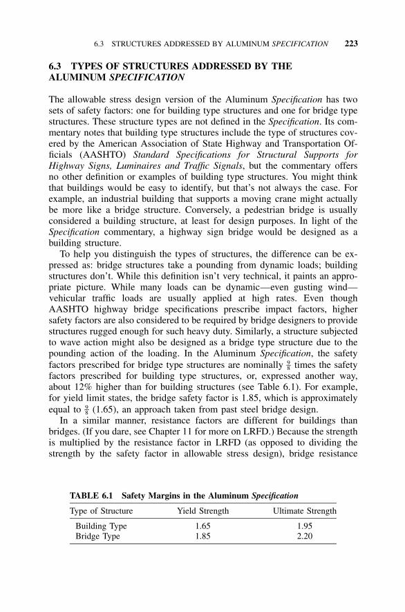
6.3 STRUCTURES ADDRESSED BY ALUMINUM SPECIFICATION 223
TABLE 6.1 Safety Margins in the Aluminum Specification
Type of Structure Yield Strength Ultimate Strength
Building Type 1.65 1.95Bridge Type 1.85 2.20
6.3 TYPES OF STRUCTURES ADDRESSED BY THEALUMINUM SPECIFICATION
The allowable stress design version of the Aluminum Specification has twosets of safety factors: one for building type structures and one for bridge typestructures. These structure types are not defined in the Specification. Its com-mentary notes that building type structures include the type of structures cov-ered by the American Association of State Highway and Transportation Of-ficials (AASHTO) Standard Specifications for Structural Supports forHighway Signs, Luminaires and Traffic Signals, but the commentary offersno other definition or examples of building type structures. You might thinkthat buildings would be easy to identify, but that’s not always the case. Forexample, an industrial building that supports a moving crane might actuallybe more like a bridge structure. Conversely, a pedestrian bridge is usuallyconsidered a building structure, at least for design purposes. In light of theSpecification commentary, a highway sign bridge would be designed as abuilding structure.
To help you distinguish the types of structures, the difference can be ex-pressed as: bridge structures take a pounding from dynamic loads; buildingstructures don’t. While this definition isn’t very technical, it paints an appro-priate picture. While many loads can be dynamic—even gusting wind—vehicular traffic loads are usually applied at high rates. Even thoughAASHTO highway bridge specifications prescribe impact factors, highersafety factors are also considered to be required by bridge designers to providestructures rugged enough for such heavy duty. Similarly, a structure subjectedto wave action might also be designed as a bridge type structure due to thepounding action of the loading. In the Aluminum Specification, the safetyfactors prescribed for bridge type structures are nominally times the safety9–8factors prescribed for building type structures, or, expressed another way,about 12% higher than for building structures (see Table 6.1). For example,for yield limit states, the bridge safety factor is 1.85, which is approximatelyequal to (1.65), an approach taken from past steel bridge design.9–8
In a similar manner, resistance factors are different for buildings thanbridges. (If you dare, see Chapter 11 for more on LRFD.) Because the strengthis multiplied by the resistance factor in LRFD (as opposed to dividing thestrength by the safety factor in allowable stress design), bridge resistance
224 ORIENTATION TO THE ALUMINUM SPECIFICATION
TABLE 6.2 Resistance Factors in the Aluminum Specification andAASHTO LRFD Bridge Design Specifications
Type of Structure Yield Strength Ultimate Strength
Building Type 0.95 0.85Bridge Type 0.90 0.75
factors are lower than building structure resistance factors. So the resistancefactor on axial tension fracture for buildings is 0.85, while the same resistancefactor for bridges is 0.75. (See Table 6.2.)
Fatigue design may also be required for bridges, but this is an entirelyadditional category of design. (See Section 9.2.) Fatigue design is triggeredby the number of times the loads are applied (usually taken as more than100,000), rather than the rate of application of the loads.
Other classes of structures are designed with different sets of safety factors.For example, lifting devices have traditionally been designed with a safetyfactor of 5, while pressure vessels and piping use 3.5. (This was recentlyrevised from 4, and the industry is still feeling slightly self-conscious aboutit, so it’s referred to as a change in the ‘‘design’’ factor rather than as areduction in the safety factor.) The Aluminum Specification allowable stressdesign version Section 1.3.3 lets designers use whatever safety factor theydeem appropriate.
All of the above assumes that the stresses remain elastic with the exceptionof some local yielding. When stresses exceed yield and considerable energyabsorption and deformation occur under the design loads, you’re in a wholenew kind of design. These situations arise, for example, when you designautomobiles or guardrails for crashworthiness and building structures forearthquakes. Although these examples demonstrate the significance of thistype of design to the aluminum industry, the Aluminum Specification is silenton this issue. More information can be found in the Aluminum Association’sAutomotive Aluminum Crash Energy Management Manual (12).
6.4 SIGNIFICANT FIGURES AND THEALUMINUM SPECIFICATION
A word on the precision of design calculations is in order here. Strengths ofaluminum alloys are stated in Aluminum Standards and Data (11) to no morethan three significant figures—for example, for 3003-H16 sheet, the minimumtensile ultimate strength listed is 24.0 ksi—and the modulus of elasticity ofthe various alloys is given to three figures in Aluminum Specification Table3.3-1. Tolerances on fabricating processes also generally limit the proper ex-pression of typical member dimensions, such as the width of an extrusion, to
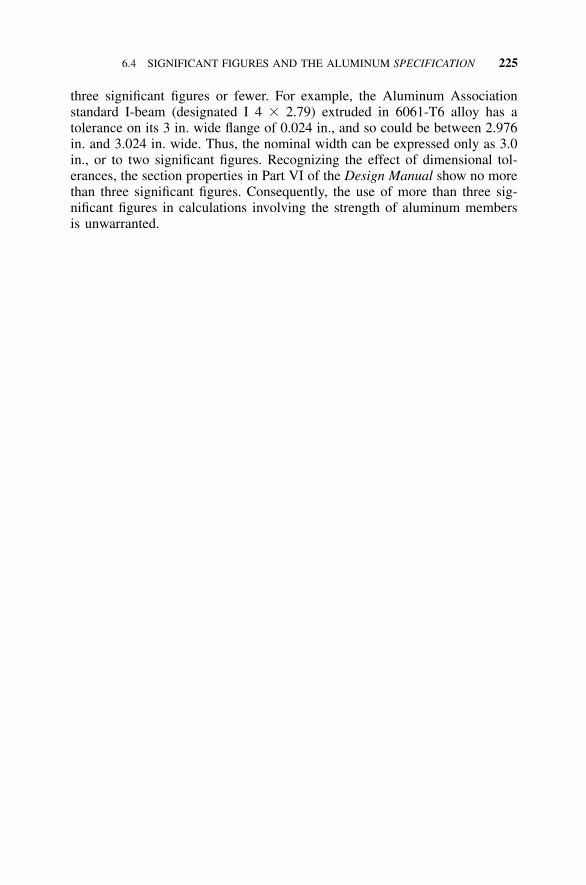
6.4 SIGNIFICANT FIGURES AND THE ALUMINUM SPECIFICATION 225
three significant figures or fewer. For example, the Aluminum Associationstandard I-beam (designated I 4 � 2.79) extruded in 6061-T6 alloy has atolerance on its 3 in. wide flange of 0.024 in., and so could be between 2.976in. and 3.024 in. wide. Thus, the nominal width can be expressed only as 3.0in., or to two significant figures. Recognizing the effect of dimensional tol-erances, the section properties in Part VI of the Design Manual show no morethan three significant figures. Consequently, the use of more than three sig-nificant figures in calculations involving the strength of aluminum membersis unwarranted.

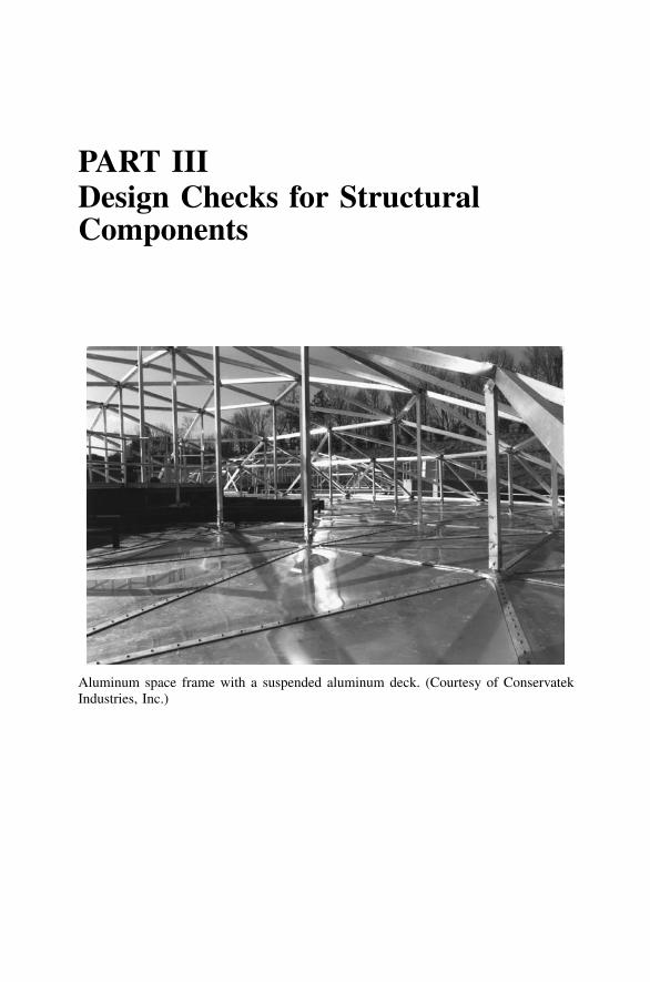
PART IIIDesign Checks for StructuralComponents
Aluminum space frame with a suspended aluminum deck. (Courtesy of ConservatekIndustries, Inc.)

229
7 Structural Members
Structural design specifications have evolved over the years into rather by-zantine formats. Unless you were intimately familiar with them, you mayhave felt you needed a guide dog to find your way to all of the provisionsapplicable to a given case. Complication seems to be the inevitable price ofthe improved precision and wider applicability specification writers and usersseek.
On the other hand, it seems that for a given mode of behavior (e.g., com-pression, tension, bending) and shape, it would be extremely useful to go toone place and find all of the required design checks listed. This would saveusers from having to sift through a general listing of provisions, most of whichdon’t apply to the case at hand.
In 1976, Galambos presented a paper at the American Society of CivilEngineers (ASCE) Annual Convention titled ‘‘History of Steel Beam Design’’(105), in which he traced the development of the steel specifications for beamsand suggested a reorganization of what he called ‘‘a patchwork of manyrevisions.’’ The 1986 Steel LRFD Specification (and 1989 Steel AllowableStress Design Specification) were based on such a reorganized format in aneffort to streamline the design process. If you want to check a beam, forexample, you go to the section on beams. There, a brief introduction identifiesthe special cases for which provisions are found elsewhere, and then thedesign checks applicable to the more typical beam problems are presented.This chapter is structured in a similar format for aluminum design.
The procedures given in this chapter are for allowable stress design; forload and resistance factor design (LRFD), follow the same approach butsubstitute design stress for allowable stress and compare to stresses producedby factored loads. (See Chapter 11 for more on LRFD.)
7.1 TENSION MEMBER DESIGN PROCEDURE
This section applies to prismatic members without welds subject to axialtension caused by forces acting through the centroidal axis. Special conditionsdiscussed elsewhere include:
Members subject to combined axial tension and bending (see Section 7.4.2)Threaded members (see Section 8.1)
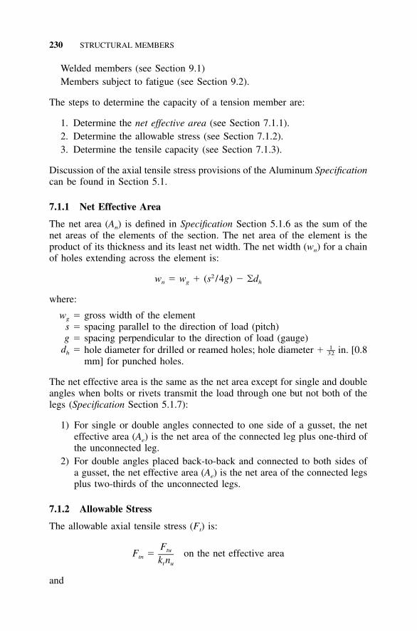
230 STRUCTURAL MEMBERS
Welded members (see Section 9.1)Members subject to fatigue (see Section 9.2).
The steps to determine the capacity of a tension member are:
1. Determine the net effective area (see Section 7.1.1).2. Determine the allowable stress (see Section 7.1.2).3. Determine the tensile capacity (see Section 7.1.3).
Discussion of the axial tensile stress provisions of the Aluminum Specificationcan be found in Section 5.1.
7.1.1 Net Effective Area
The net area (An) is defined in Specification Section 5.1.6 as the sum of thenet areas of the elements of the section. The net area of the element is theproduct of its thickness and its least net width. The net width (wn) for a chainof holes extending across the element is:
2w � w � (s /4g) � �dn g h
where:
wg � gross width of the elements � spacing parallel to the direction of load (pitch)g � spacing perpendicular to the direction of load (gauge)
dh � hole diameter for drilled or reamed holes; hole diameter � in. [0.81––32
mm] for punched holes.
The net effective area is the same as the net area except for single and doubleangles when bolts or rivets transmit the load through one but not both of thelegs (Specification Section 5.1.7):
1) For single or double angles connected to one side of a gusset, the neteffective area (Ae) is the net area of the connected leg plus one-third ofthe unconnected leg.
2) For double angles placed back-to-back and connected to both sides ofa gusset, the net effective area (Ae) is the net area of the connected legsplus two-thirds of the unconnected legs.
7.1.2 Allowable Stress
The allowable axial tensile stress (Ft) is:
FtuF � on the net effective areatn k nt u
and
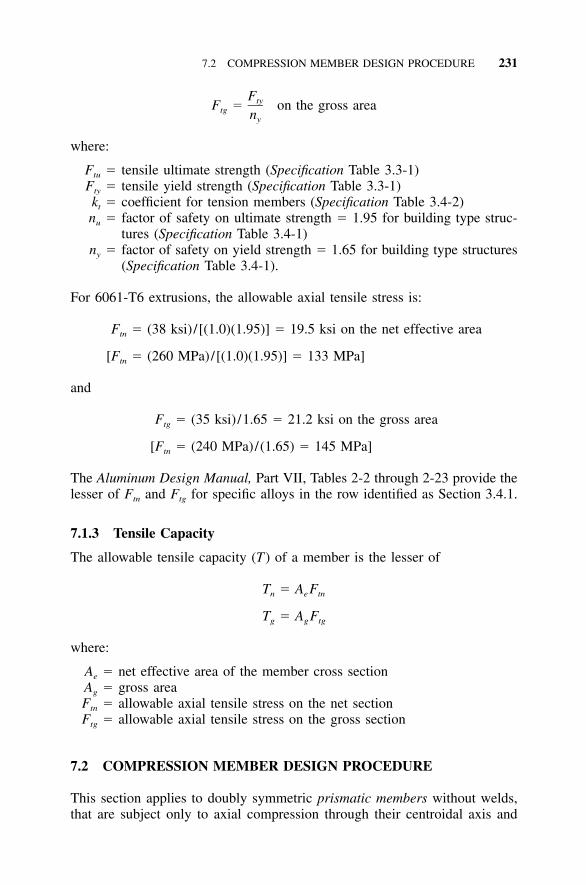
7.2 COMPRESSION MEMBER DESIGN PROCEDURE 231
FtyF � on the gross areatg ny
where:
Ftu � tensile ultimate strength (Specification Table 3.3-1)Fty � tensile yield strength (Specification Table 3.3-1)kt � coefficient for tension members (Specification Table 3.4-2)nu � factor of safety on ultimate strength � 1.95 for building type struc-
tures (Specification Table 3.4-1)ny � factor of safety on yield strength � 1.65 for building type structures
(Specification Table 3.4-1).
For 6061-T6 extrusions, the allowable axial tensile stress is:
F � (38 ksi) /[(1.0)(1.95)] � 19.5 ksi on the net effective areatn
[F � (260 MPa)/[(1.0)(1.95)] � 133 MPa]tn
and
F � (35 ksi) /1.65 � 21.2 ksi on the gross areatg
[F � (240 MPa)/(1.65) � 145 MPa]tn
The Aluminum Design Manual, Part VII, Tables 2-2 through 2-23 provide thelesser of Ftn and Ftg for specific alloys in the row identified as Section 3.4.1.
7.1.3 Tensile Capacity
The allowable tensile capacity (T) of a member is the lesser of
T � A Fn e tn
T � A Fg g tg
where:
Ae � net effective area of the member cross sectionAg � gross areaFtn � allowable axial tensile stress on the net sectionFtg � allowable axial tensile stress on the gross section
7.2 COMPRESSION MEMBER DESIGN PROCEDURE
This section applies to doubly symmetric prismatic members without welds,that are subject only to axial compression through their centroidal axis and
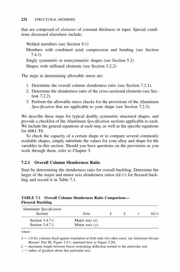
232 STRUCTURAL MEMBERS
TABLE 7.1 Overall Column Slenderness Ratio Comparison—Flexural Buckling
Aluminum SpecificationSection Axis k L r kL /r
Section 3.4.7.1 Major axis (x)Section 3.4.7.1 Minor axis (y)
where:
k � 1.0 for columns fixed against translation at both ends (for other cases, see Aluminum DesignManual. Part III, Figure 3.4-1, reprinted here as Figure 5.20).
L � maximum length between braces restraining deflection normal to the particular axisr � radius of gyration about that particular axis.
that are composed of elements of constant thickness or taper. Special condi-tions discussed elsewhere include:
Welded members (see Section 9.1)Members with combined axial compression and bending (see Section
7.4.1)Singly symmetric or nonsymmetric shapes (see Section 5.2)Shapes with stiffened elements (see Section 5.2.2)
The steps in determining allowable stress are:
1. Determine the overall column slenderness ratio (see Section 7.2.1).2. Determine the slenderness ratio of the cross-sectional elements (see Sec-
tion 7.2.2).3. Perform the allowable stress checks for the provisions of the Aluminum
Specification that are applicable to your shape (see Section 7.2.3).
We describe these steps for typical doubly symmetric structural shapes, andprovide a checklist of the Aluminum Specification sections applicable to each.We include the general equations at each step, as well as the specific equationsfor 6061-T6.
To check the capacity of a certain shape or to compare several commonlyavailable shapes, simply substitute the values for your alloy and shape for thevariables in this section. Should you have questions on the provisions as youwork through them, refer to Chapter 5.
7.2.1 Overall Column Slenderness Ratio
Start by determining the slenderness ratio for overall buckling. Determine thelarger of the major and minor axis slenderness ratios (kL /r) for flexural buck-ling and record it in Table 7.1.
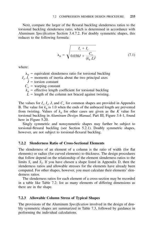
7.2 COMPRESSION MEMBER DESIGN PROCEDURE 233
Next, compare the larger of the flexural buckling slenderness ratios to thetorsional buckling slenderness ratio, which is determined in accordance withAluminum Specification Section 3.4.7.2. For doubly symmetric shapes, thisreduces to the following formula:
I � Ix y
Cw� � (7.1)� 0.038J � 2(k L)
where:
� � equivalent slenderness ratio for torsional bucklingIx, Iy � moments of inertia about the two principal axes
J � torsion constantCw � warping constantk � effective length coefficient for torsional bucklingL � length of the column not braced against twisting.
The values for Ix, Iy, J, and Cw for common shapes are provided in AppendixB. The value for k is 1.0 when the ends of the unbraced length are preventedfrom twisting. Values of k for other cases are given as the K value fortorsional buckling in Aluminum Design Manual, Part III, Figure 3.4-1, foundhere in Figure 5.20.
Singly symmetric and nonsymmetric shapes may further be subject totorsional-flexural buckling (see Section 5.2.1). Doubly symmetric shapes,however, are not subject to torsional-flexural buckling.
7.2.2 Slenderness Ratio of Cross-Sectional Elements
The slenderness of an element of a column is the ratio of width (for flatelements) or radius (for curved elements) to thickness. The design proceduresthat follow depend on the relationship of the element slenderness ratios to thelimits S1 and S2. If you have chosen a shape listed in Appendix D, then theslenderness ratios and allowable stresses for the elements have already beencomputed. For other shapes, however, you must calculate their elements’ slen-derness ratios.
The slenderness ratios for each element of a cross-section may be recordedin a table like Table 7.2; list as many elements of differing dimensions asthere are in the shape.
7.2.3 Allowable Column Stress of Typical Shapes
The provisions of the Aluminum Specification involved in the design of dou-bly symmetric shapes are summarized in Table 7.3, followed by guidance inperforming the individual calculations.
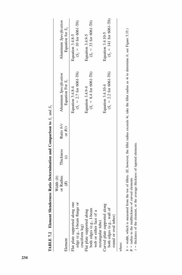
234
TA
BL
E7.
2E
lem
ent
Slen
dern
ess
Rat
ioD
eter
min
atio
nan
dC
ompa
riso
nto
S 1an
dS 2
Ele
men
t
Wid
th(b
)or
Rad
ius
(R)
Thi
ckne
ss(t
)R
atio
b/t
orR
/tA
lum
inum
Spec
ifica
tion
Equ
atio
nFo
rS 1
Alu
min
umSp
ecifi
cati
onE
quat
ion
for
S 2
Flat
plat
esu
ppor
ted
alon
gon
eed
ge(e
.g.,
I-be
amfla
nge
orcr
ucif
orm
leg)
Equ
atio
n3.
4.8-
4(S
1�
2.7
for
6061
-T6)
Equ
atio
n3.
4.8-
5(S
2�
10fo
r60
61-T
6)
Flat
plat
esu
ppor
ted
alon
gbo
thed
ges
(e.g
.,I-
beam
web
orei
ther
face
ofa
rect
angu
lar
tube
)
Equ
atio
n3.
4.9-
4(S
1�
8.4
for
6061
-T6)
Equ
atio
n3.
4.9-
5(S
2�
33fo
r60
61-T
6)
Cur
ved
plat
esu
ppor
ted
alon
gbo
thed
ges
(e.g
.,w
all
ofro
und
orov
altu
bes)
Equ
atio
n3.
4.10
-4(S
1�
2.2
for
6061
-T6)
Equ
atio
n3.
4.10
-5(S
2�
141
for
6061
-T6)
whe
re:
b�
wid
th,
whi
chis
mea
sure
dfr
omth
eto
eof
fille
ts.
(If,
how
ever
,th
efil
let
radi
usex
ceed
s4t
,ta
keth
efil
let
radi
usas
4tto
dete
rmin
eb;
see
Figu
re5.
35.)
R�
radi
usto
the
mid
thic
knes
sof
curv
edel
emen
tst
�th
ickn
ess
ofth
eel
emen
t,or
the
aver
age
thic
knes
sof
tape
red
elem
ents
.
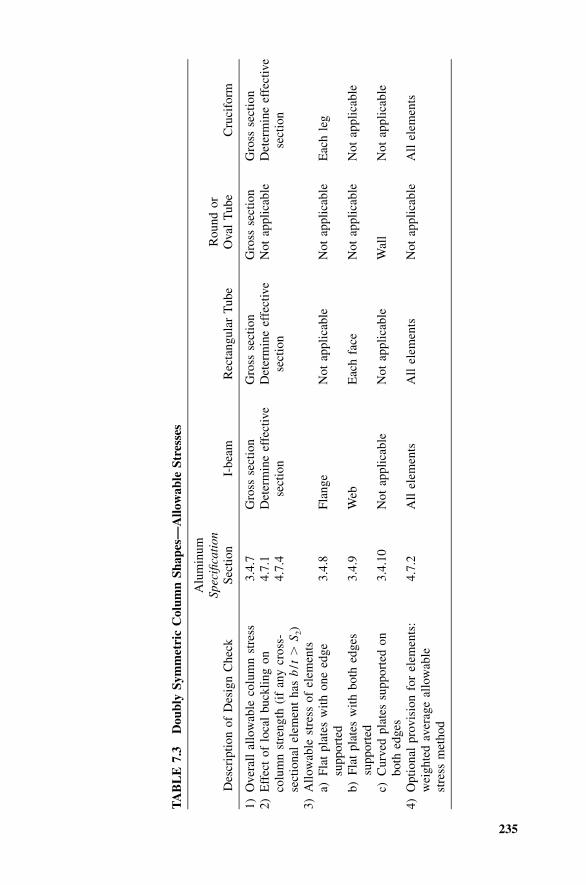
235
TA
BL
E7.
3D
oubl
ySy
mm
etri
cC
olum
nSh
apes
—A
llow
able
Stre
sses
Des
crip
tion
ofD
esig
nC
heck
Alu
min
umSp
ecifi
cati
onSe
ctio
nI-
beam
Rec
tang
ular
Tub
eR
ound
orO
val
Tub
eC
ruci
form
1)O
vera
llal
low
able
colu
mn
stre
ss3.
4.7
Gro
ssse
ctio
nG
ross
sect
ion
Gro
ssse
ctio
nG
ross
sect
ion
2)E
ffec
tof
loca
lbu
cklin
gon
colu
mn
stre
ngth
(if
any
cros
s-se
ctio
nal
elem
ent
has
b/t
�S 2
)
4.7.
14.
7.4
Det
erm
ine
effe
ctiv
ese
ctio
nD
eter
min
eef
fect
ive
sect
ion
Not
appl
icab
leD
eter
min
eef
fect
ive
sect
ion
3)A
llow
able
stre
ssof
elem
ents
a)Fl
atpl
ates
with
one
edge
supp
orte
d3.
4.8
Flan
geN
otap
plic
able
Not
appl
icab
leE
ach
leg
b)Fl
atpl
ates
with
both
edge
ssu
ppor
ted
3.4.
9W
ebE
ach
face
Not
appl
icab
leN
otap
plic
able
c)C
urve
dpl
ates
supp
orte
don
both
edge
s3.
4.10
Not
appl
icab
leN
otap
plic
able
Wal
lN
otap
plic
able
4)O
ptio
nal
prov
isio
nfo
rel
emen
ts:
wei
ghte
dav
erag
eal
low
able
stre
ssm
etho
d
4.7.
2A
llel
emen
tsA
llel
emen
tsN
otap
plic
able
All
elem
ents
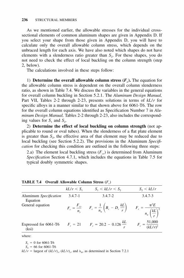
236 STRUCTURAL MEMBERS
TABLE 7.4 Overall Allowable Column Stress (Fc)
kL /r � S1 S1 � kL /r � S2 S2 � kL /r
Aluminum SpecificationEquation
3.4.7-1 3.4.7-2 3.4.7-3
General equation FcyF �c ny
1 kLF � B � D� �c c cn ru
2� EF �c 2kL
n � �u r
Expressed for 6061-T6(ksi)
Fc � 21kL
F � 20.2 � 0.126c r51,000
F �c 2(kL /r)
where:
S1 � 0 for 6061-T6S2 � 66 for 6061-T6
kL /r � largest of (kL /r)x, (kL /r)y, and �, as determined in Section 7.2.1
As we mentioned earlier, the allowable stresses for the individual cross-sectional elements of common aluminum shapes are given in Appendix D. Ifyou select your shape from those given in Appendix D, you will have tocalculate only the overall allowable column stress, which depends on theunbraced length for each axis. We have also noted which shapes do not haveelements with a slenderness ratio greater than S2. For these shapes, you donot need to check the effect of local buckling on the column strength (step2, below).
The calculations involved in these steps follow:
1) Determine the overall allowable column stress (Fc). The equation forthe allowable column stress is dependent on the overall column slendernessratio, as shown in Table 7.4. We discuss the variables in the general equationsfor overall column buckling in Section 5.2.1. The Aluminum Design Manual,Part VII, Tables 2-2 through 2-23, presents solutions in terms of kL /r forspecific alloys in a manner similar to that shown above for 6061-T6. The rowfor the overall column equations identified as Specification Number 7 in Alu-minum Design Manual, Tables 2-2 through 2-23, also includes the correspond-ing values for S1 and S2.
2) Determine the effect of local buckling on column strength (not ap-plicable to round or oval tubes). When the slenderness of a flat plate elementis greater than S2, the effective area of that element may be reduced due tolocal buckling (see Section 5.2.2). The provisions in the Aluminum Specifi-cation for checking this condition are outlined in the following three steps:
2.a) The element local buckling stress (Fcr) is determined from AluminumSpecification Section 4.7.1, which includes the equations in Table 7.5 fortypical doubly symmetric shapes.
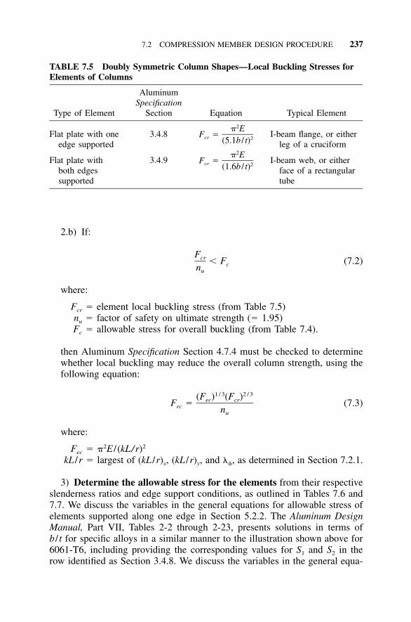
7.2 COMPRESSION MEMBER DESIGN PROCEDURE 237
TABLE 7.5 Doubly Symmetric Column Shapes—Local Buckling Stresses forElements of Columns
Type of Element
AluminumSpecification
Section Equation Typical Element
Flat plate with oneedge supported
3.4.82� E
F �cr 2(5.1b / t)I-beam flange, or either
leg of a cruciform
Flat plate withboth edgessupported
3.4.92� E
F �cr 2(1.6b / t)I-beam web, or either
face of a rectangulartube
2.b) If:
Fcr � F (7.2)cnu
where:
Fcr � element local buckling stress (from Table 7.5)nu � factor of safety on ultimate strength (� 1.95)Fc � allowable stress for overall buckling (from Table 7.4).
then Aluminum Specification Section 4.7.4 must be checked to determinewhether local buckling may reduce the overall column strength, using thefollowing equation:
1 / 3 2 / 3(F ) (F )ec crF � (7.3)rc nu
where:
Fec � �2E / (kL/r)2
kL /r � largest of (kL /r)x, (kL /r)y, and �, as determined in Section 7.2.1.
3) Determine the allowable stress for the elements from their respectiveslenderness ratios and edge support conditions, as outlined in Tables 7.6 and7.7. We discuss the variables in the general equations for allowable stress ofelements supported along one edge in Section 5.2.2. The Aluminum DesignManual, Part VII, Tables 2-2 through 2-23, presents solutions in terms ofb / t for specific alloys in a similar manner to the illustration shown above for6061-T6, including providing the corresponding values for S1 and S2 in therow identified as Section 3.4.8. We discuss the variables in the general equa-
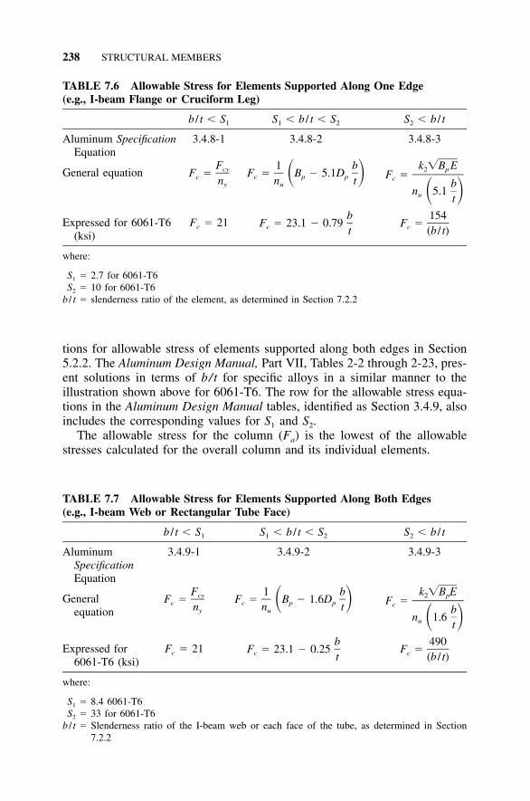
238 STRUCTURAL MEMBERS
TABLE 7.6 Allowable Stress for Elements Supported Along One Edge(e.g., I-beam Flange or Cruciform Leg)
b / t � S1 S1 � b / t � S2 S2 � b / t
Aluminum SpecificationEquation
3.4.8-1 3.4.8-2 3.4.8-3
General equationFcyF �c ny
1 bF � B � 5.1D� �c p pn tu
k �B E2 pF �c
bn 5.1� �u t
Expressed for 6061-T6(ksi)
Fc � 21b
F � 23.1 � 0.79c t154
F �c (b / t)
where:
S1 � 2.7 for 6061-T6S2 � 10 for 6061-T6
b / t � slenderness ratio of the element, as determined in Section 7.2.2
TABLE 7.7 Allowable Stress for Elements Supported Along Both Edges(e.g., I-beam Web or Rectangular Tube Face)
b / t � S1 S1 � b / t � S2 S2 � b / t
AluminumSpecificationEquation
3.4.9-1 3.4.9-2 3.4.9-3
Generalequation
FcyF �c ny
1 bF � B � 1.6D� �c p pn tu
k �B E2 pF �c
bn 1.6� �u t
Expressed for6061-T6 (ksi)
Fc � 21b
F � 23.1 � 0.25c t490
F �c (b / t)
where:
S1 � 8.4 6061-T6S2 � 33 for 6061-T6
b / t � Slenderness ratio of the I-beam web or each face of the tube, as determined in Section7.2.2
tions for allowable stress of elements supported along both edges in Section5.2.2. The Aluminum Design Manual, Part VII, Tables 2-2 through 2-23, pres-ent solutions in terms of b/t for specific alloys in a similar manner to theillustration shown above for 6061-T6. The row for the allowable stress equa-tions in the Aluminum Design Manual tables, identified as Section 3.4.9, alsoincludes the corresponding values for S1 and S2.
The allowable stress for the column (Fa) is the lowest of the allowablestresses calculated for the overall column and its individual elements.
7.3 BENDING MEMBER DESIGN PROCEDURE 239
4) Weighted average allowable stress. When the allowable stress of oneelement is significantly lower than those of other elements and is controllingthe design of the column, it may be beneficial to employ the weighted methodof averaging the allowable stresses for the individual cross-sectional elements.
The weighted average allowable stress method was discussed in Section5.2.2, and summarized in Equation 5.22. For easy reference, it is repeatedbelow as Equation 7.4:
A F � A F � ��� � A F1 c1 2 c2 n cnF � (7.4)ca A
where:
Fca � weighted average allowable compressive stressAi � the area of element i
Fci � local buckling allowable stress of element iA � area of the section (A1 � A2 � ��� � An).
7.2.4 Summary of Allowable Column Stress
Table 7.8 provides a format for comparing the allowable stresses calculatedfor the overall column and its individual elements. As you work through theprocedure of Section 7.2.3, you can enter the value of each allowable stressinto the appropriate cell in Table 7.8.
After you record the values for each of the applicable provisions, you canreadily select the allowable column stress (Fa) by inspection. If you havecalculated the weighted average allowable stress, take it as the element allow-able stress. Otherwise, select the lowest allowable stress calculated for anindividual element as the element allowable stress. Compare the element al-lowable stress to the reduced allowable column stress, if applicable, or to theoverall allowable column stress. The allowable column stress (Fa) to be usedfor design is the lower of the individual element allowable stress and theoverall allowable column stress.
7.3 BENDING MEMBER DESIGN PROCEDURE
This section applies to single web and box beams bent about their major axis,without welds, that are composed of elements of constant thickness or taper.Special conditions discussed elsewhere include:
Members subject to combined axial compression and bending (see Section7.4.1)
Members subject to combined axial tension and bending (see Section 7.4.2)Welded members (see Section 9.1)Members subject to fatigue (see Section 9.2).
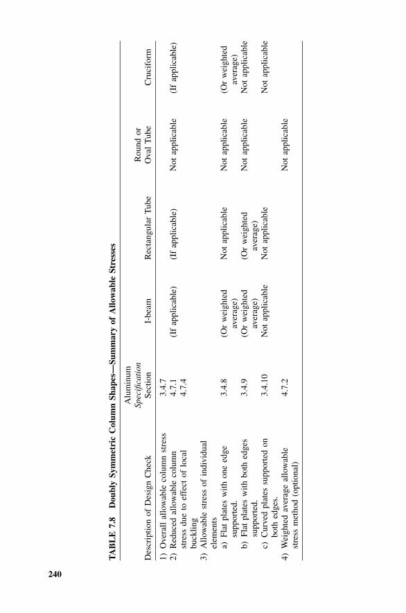
240
TA
BL
E7.
8D
oubl
ySy
mm
etri
cC
olum
nSh
apes
—Su
mm
ary
ofA
llow
able
Stre
sses
Des
crip
tion
ofD
esig
nC
heck
Alu
min
umSp
ecifi
cati
onSe
ctio
nI-
beam
Rec
tang
ular
Tub
eR
ound
orO
val
Tub
eC
ruci
form
1)O
vera
llal
low
able
colu
mn
stre
ss3.
4.7
2)R
educ
edal
low
able
colu
mn
stre
ssdu
eto
effe
ctof
loca
lbu
cklin
g
4.7.
14.
7.4
(If
appl
icab
le)
(If
appl
icab
le)
Not
appl
icab
le(I
fap
plic
able
)
3)A
llow
able
stre
ssof
indi
vidu
alel
emen
tsa)
Flat
plat
esw
ithon
eed
gesu
ppor
ted.
3.4.
8(O
rw
eigh
ted
aver
age)
Not
appl
icab
leN
otap
plic
able
(Or
wei
ghte
dav
erag
e)b)
Flat
plat
esw
ithbo
thed
ges
supp
orte
d.3.
4.9
(Or
wei
ghte
dav
erag
e)(O
rw
eigh
ted
aver
age)
Not
appl
icab
leN
otap
plic
able
c)C
urve
dpl
ates
supp
orte
don
both
edge
s.3.
4.10
Not
appl
icab
leN
otap
plic
able
Not
appl
icab
le
4)W
eigh
ted
aver
age
allo
wab
lest
ress
met
hod
(opt
iona
l)4.
7.2
Not
appl
icab
le
7.3 BENDING MEMBER DESIGN PROCEDURE 241
The steps to determine the allowable stresses for a beam are:
1. Determine the allowable bending tensile stress (see Section 7.3.1).2. Determine the allowable bending compressive stress (see Section 7.3.2).3. Determine the allowable shear stress (see Section 7.3.3).
Discussion of the beam design provisions of the Aluminum Specification canbe found in Section 5.3.
7.3.1 Bending Tension
The allowable bending tensile stress (Fbt) for structural shapes bent about thestrong axis and rectangular tubes is:
F � min[F / (k n ) and F /n ] (7.5)bt tu t u ty y
For 6061-T6 extrusions, the allowable bending tensile stress is
F � min[(38 ksi) /[(1.0)(1.95)] and (35 ksi)/(1.65)]bt
F � min[19.5 ksi and 21.2 ksi] � 19.5 ksi on the net areabt
[F � min[(260 MPa)/[(1.0)(1.95)] and (240 MPa)/(1.65)]bt
F � min[133 MPa and 145 MPa] � 133 MPa on the net area]bt
where:
Ftu � tensile ultimate strength (Specification Table 3.3-1)Fty � tensile yield strength (Specification Table 3.3-1)kt � coefficient for tension members (Specification Table 3.4-2)nu � factor of safety on ultimate strength � 1.95 for building type struc-
tures (Specification Table 3.4-1)ny � factor of safety on yield strength � 1.65 for building type structures
(Specification Table 3.4-1)
The Aluminum Design Manual, Part VII, Tables 2-2 through 2-23, presentsallowable bending tensile stresses for specific alloys in the rows identified asSection 3.4.2, 3.4.3, and 3.4.4.
7.3.2 Bending Compression
To determine the allowable bending compression stress:
1) Determine the lateral buckling allowable stress. The lateral bucklingallowable stress is determined from the shape of the beam section in accord-
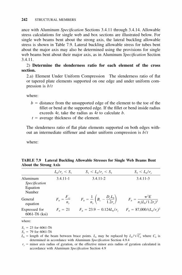
242 STRUCTURAL MEMBERS
TABLE 7.9 Lateral Buckling Allowable Stresses for Single Web Beams BentAbout the Strong Axis
Lb /ry � S1 S1 � Lb /ry � S2 S2 � Lb /ry
AluminumSpecificationEquationNumber
3.4.11-1 3.4.11-2 3.4.11-3
Generalequation
FcyF �b ny
1 D Lc bF � B �� �b cn 1.2ry y
2� EF �b 2n (L /1.2r )y b y
Expressed for6061-T6 (ksi)
Fb � 21 F � 23.9 � 0.124L /rb b y2F � 87,000/(L /r )b b y
where:
S1 � 23 for 6061-T6S2 � 79 for 6061-T6Lb � length of the beam between brace points. Lb may be replaced by Lb / where Cb is�Cb
determined in accordance with Aluminum Specification Section 4.9.4ry � minor axis radius of gyration, or the effective minor axis radius of gyration calculated in
accordance with Aluminum Specification Section 4.9
ance with Aluminum Specification Sections 3.4.11 through 3.4.14. Allowablestress calculations for single web and box sections are illustrated below. Forsingle web beams bent about the strong axis, the lateral buckling allowablestress is shown in Table 7.9. Lateral buckling allowable stress for tubes bentabout the major axis may also be determined using the provisions for singleweb beams bent about their major axis, as in Aluminum Specification Section3.4.11.
2) Determine the slenderness ratio for each element of the crosssection.
2.a) Element Under Uniform Compression The slenderness ratio of flator tapered plate elements supported on one edge and under uniform com-pression is b / t
where:
b � distance from the unsupported edge of the element to the toe of thefillet or bend at the supported edge. If the fillet or bend inside radiusexceeds 4t, take the radius as 4t to calculate b.
t � average thickness of the element.
The slenderness ratio of flat plate elements supported on both edges with-out an intermediate stiffener and under uniform compression is b / t
where:
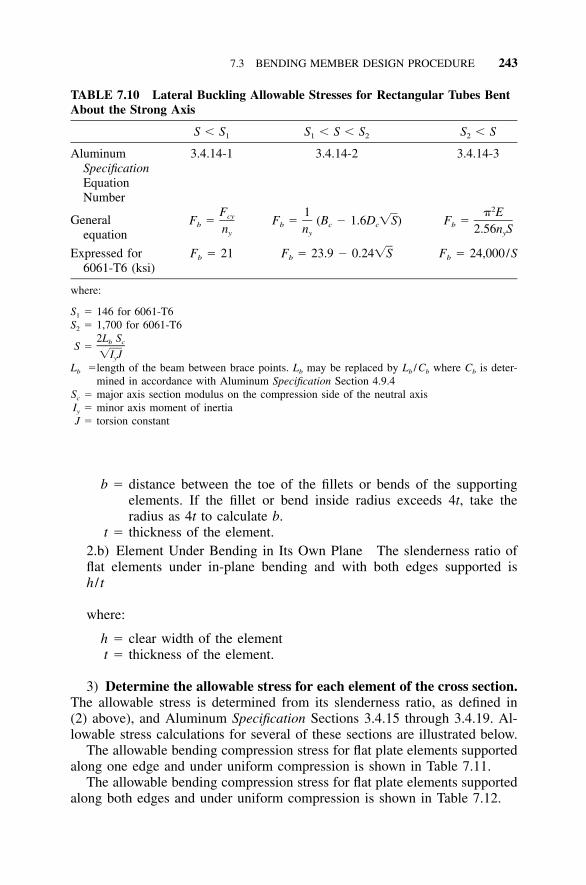
7.3 BENDING MEMBER DESIGN PROCEDURE 243
TABLE 7.10 Lateral Buckling Allowable Stresses for Rectangular Tubes BentAbout the Strong Axis
S � S1 S1 � S � S2 S2 � S
AluminumSpecificationEquationNumber
3.4.14-1 3.4.14-2 3.4.14-3
Generalequation
FcyF �b ny
1F � (B � 1.6D �S)b c cny
2� EF �b 2.56n Sy
Expressed for6061-T6 (ksi)
Fb � 21 F � 23.9 � 0.24�Sb Fb � 24,000/S
where:
S1 � 146 for 6061-T6S2 � 1,700 for 6061-T6
S �2L Sb c
�I Jy
Lb �length of the beam between brace points. Lb may be replaced by Lb /Cb where Cb is deter-mined in accordance with Aluminum Specification Section 4.9.4
Sc � major axis section modulus on the compression side of the neutral axisIy � minor axis moment of inertiaJ � torsion constant
b � distance between the toe of the fillets or bends of the supportingelements. If the fillet or bend inside radius exceeds 4t, take theradius as 4t to calculate b.
t � thickness of the element.2.b) Element Under Bending in Its Own Plane The slenderness ratio offlat elements under in-plane bending and with both edges supported ish / t
where:
h � clear width of the elementt � thickness of the element.
3) Determine the allowable stress for each element of the cross section.The allowable stress is determined from its slenderness ratio, as defined in(2) above), and Aluminum Specification Sections 3.4.15 through 3.4.19. Al-lowable stress calculations for several of these sections are illustrated below.
The allowable bending compression stress for flat plate elements supportedalong one edge and under uniform compression is shown in Table 7.11.
The allowable bending compression stress for flat plate elements supportedalong both edges and under uniform compression is shown in Table 7.12.
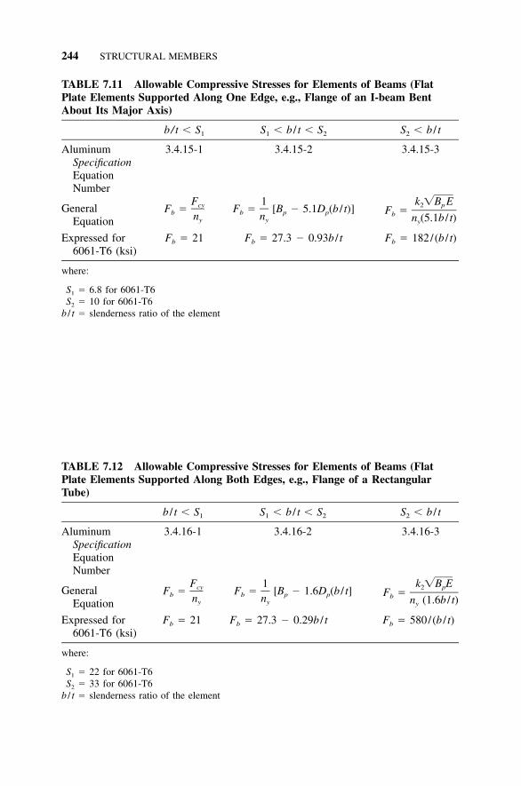
244 STRUCTURAL MEMBERS
TABLE 7.11 Allowable Compressive Stresses for Elements of Beams (FlatPlate Elements Supported Along One Edge, e.g., Flange of an I-beam BentAbout Its Major Axis)
b/ t � S1 S1 � b / t � S2 S2 � b / t
AluminumSpecificationEquationNumber
3.4.15-1 3.4.15-2 3.4.15-3
GeneralEquation
FcyF �b ny
1F � [B � 5.1D (b / t)]b p pny
k �B E2 pF �b n (5.1b / t)y
Expressed for6061-T6 (ksi)
Fb � 21 Fb � 27.3 � 0.93b / t Fb � 182/(b / t)
where:
S1 � 6.8 for 6061-T6S2 � 10 for 6061-T6
b / t � slenderness ratio of the element
TABLE 7.12 Allowable Compressive Stresses for Elements of Beams (FlatPlate Elements Supported Along Both Edges, e.g., Flange of a RectangularTube)
b / t � S1 S1 � b / t � S2 S2 � b / t
AluminumSpecificationEquationNumber
3.4.16-1 3.4.16-2 3.4.16-3
GeneralEquation
FcyF �b ny
1F � [B � 1.6D (b / t]b p pny
k �B E2 pF �b n (1.6b / t)y
Expressed for6061-T6 (ksi)
Fb � 21 Fb � 27.3 � 0.29b / t Fb � 580/(b / t)
where:
S1 � 22 for 6061-T6S2 � 33 for 6061-T6
b / t � slenderness ratio of the element
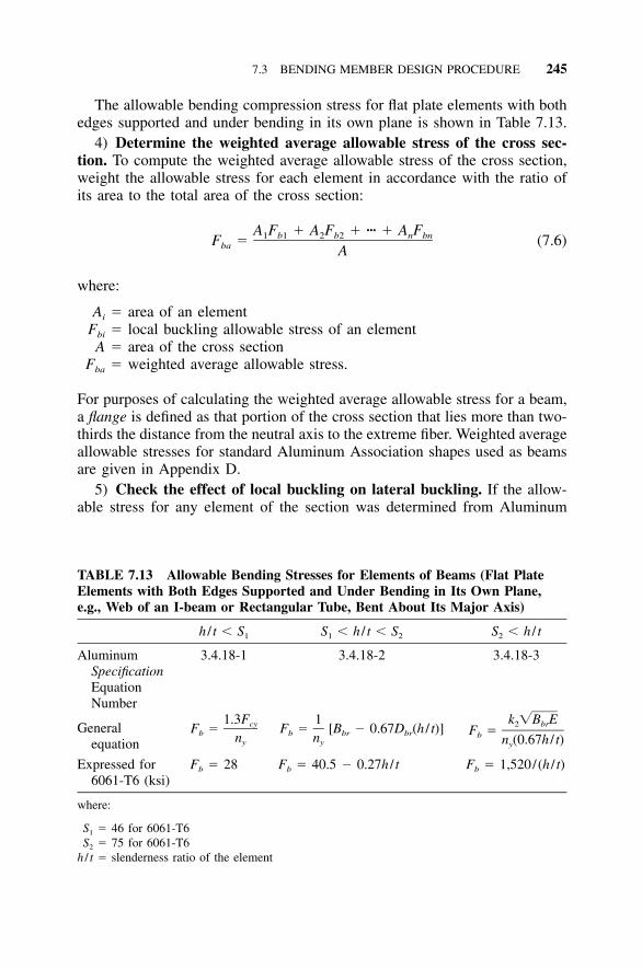
7.3 BENDING MEMBER DESIGN PROCEDURE 245
TABLE 7.13 Allowable Bending Stresses for Elements of Beams (Flat PlateElements with Both Edges Supported and Under Bending in Its Own Plane,e.g., Web of an I-beam or Rectangular Tube, Bent About Its Major Axis)
h / t � S1 S1 � h / t � S2 S2 � h / t
AluminumSpecificationEquationNumber
3.4.18-1 3.4.18-2 3.4.18-3
Generalequation
1.3FcyF �b ny
1F � [B � 0.67D (h / t)]b br brny
k �B E2 brF �b n (0.67h / t)y
Expressed for6061-T6 (ksi)
Fb � 28 Fb � 40.5 � 0.27h / t Fb � 1,520/(h / t)
where:
S1 � 46 for 6061-T6S2 � 75 for 6061-T6
h / t � slenderness ratio of the element
The allowable bending compression stress for flat plate elements with bothedges supported and under bending in its own plane is shown in Table 7.13.
4) Determine the weighted average allowable stress of the cross sec-tion. To compute the weighted average allowable stress of the cross section,weight the allowable stress for each element in accordance with the ratio ofits area to the total area of the cross section:
A F � A F � ��� � A F1 b1 2 b2 n bnF � (7.6)ba A
where:
Ai � area of an elementFbi � local buckling allowable stress of an element
A � area of the cross sectionFba � weighted average allowable stress.
For purposes of calculating the weighted average allowable stress for a beam,a flange is defined as that portion of the cross section that lies more than two-thirds the distance from the neutral axis to the extreme fiber. Weighted averageallowable stresses for standard Aluminum Association shapes used as beamsare given in Appendix D.
5) Check the effect of local buckling on lateral buckling. If the allow-able stress for any element of the section was determined from Aluminum
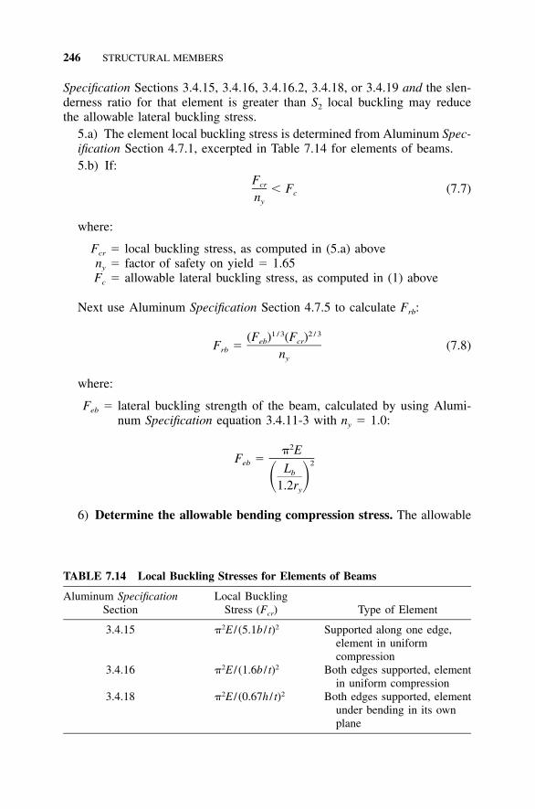
246 STRUCTURAL MEMBERS
TABLE 7.14 Local Buckling Stresses for Elements of Beams
Aluminum SpecificationSection
Local BucklingStress (Fcr) Type of Element
3.4.15 �2E / (5.1b / t)2 Supported along one edge,element in uniformcompression
3.4.16 �2E / (1.6b / t)2 Both edges supported, elementin uniform compression
3.4.18 �2E / (0.67h / t)2 Both edges supported, elementunder bending in its ownplane
Specification Sections 3.4.15, 3.4.16, 3.4.16.2, 3.4.18, or 3.4.19 and the slen-derness ratio for that element is greater than S2 local buckling may reducethe allowable lateral buckling stress.
5.a) The element local buckling stress is determined from Aluminum Spec-ification Section 4.7.1, excerpted in Table 7.14 for elements of beams.5.b) If:
Fcr � F (7.7)cny
where:
Fcr � local buckling stress, as computed in (5.a) aboveny � factor of safety on yield � 1.65Fc � allowable lateral buckling stress, as computed in (1) above
Next use Aluminum Specification Section 4.7.5 to calculate Frb:
1 / 3 2 / 3(F ) (F )eb crF � (7.8)rb ny
where:
Feb � lateral buckling strength of the beam, calculated by using Alumi-num Specification equation 3.4.11-3 with ny � 1.0:
2� EF �eb 2Lb� �1.2ry
6) Determine the allowable bending compression stress. The allowable
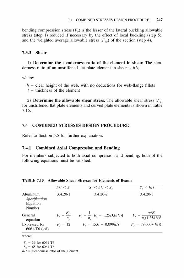
7.4 COMBINED STRESSES DESIGN PROCEDURE 247
TABLE 7.15 Allowable Shear Stresses for Elements of Beams
h / t � S1 S1 � h / t � S2 S2 � h / t
AluminumSpecificationEquationNumber
3.4.20-1 3.4.20-2 3.4.20-3
Generalequation
FsyF �s ny
1F � [B � 1.25D (h / t)]s s sny
2� EF �s 2n (1.25h / t)y
Expressed for6061-T6 (ksi)
Fs � 12 Fs � 15.6 � 0.099h / t Fs � 39,000/(h / t)2
where:
S1 � 36 for 6061-T6S2 � 65 for 6061-T6
h / t � slenderness ratio of the element.
bending compression stress (Fb) is the lesser of the lateral buckling allowablestress (step 1) reduced if necessary by the effect of local buckling (step 5),and the weighted average allowable stress (Fba) of the section (step 4).
7.3.3 Shear
1) Determine the slenderness ratio of the element in shear. The slen-derness ratio of an unstiffened flat plate element in shear is h / t,
where:
h � clear height of the web, with no deductions for web-flange filletst � thickness of the element
2) Determine the allowable shear stress. The allowable shear stress (Fs)for unstiffened flat plate elements and curved plate elements is shown in Table7.15.
7.4 COMBINED STRESSES DESIGN PROCEDURE
Refer to Section 5.5 for further explanation.
7.4.1 Combined Axial Compression and Bending
For members subjected to both axial compression and bending, both of thefollowing equations must be satisfied:
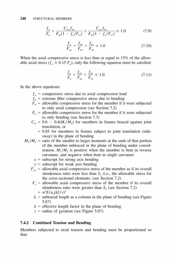
248 STRUCTURAL MEMBERS
ƒ C ƒ C ƒa mx bx my by� � � 1.0 (7.9)F F (1 � ƒ /F ) F (1 � ƒ /F )a bx a ex by a ev
ƒ ƒ ƒa bx by� � � 1.0 (7.10)F F Fao bx by
When the axial compressive stress is less than or equal to 15% of the allow-able axial stress (ƒa � 0.15 Fa), only the following equation must be satisfied:
ƒ ƒ ƒa bx by� � � 1.0 (7.11)F F Fa bx by
In the above equations:
ƒa � compressive stress due to axial compression loadƒb � extreme fiber compressive stress due to bendingFa � allowable compressive stress for the member if it were subjected
to only axial compression (see Section 7.2)Fb � allowable compressive stress for the member if it were subjected
to only bending (see Section 7.3)Cm � 0.6 � 0.4(M1 /M2) for members in frames braced against joint
translation, or� 0.85 for members in frames subject to joint translation (side-
sway) in the plane of bendingM1 /M2 � ratio of the smaller to larger moments at the ends of that portion
of the member unbraced in the plane of bending under consid-eration. M1 /M2 is positive when the member is bent in reversecurvature, and negative when bent in single curvature
x � subscript for strong axis bendingy � subscript for weak axis bending
Fao � allowable axial compressive stress of the member as if its overallslenderness ratio were less than S1 (i.e., the allowable stress forthe cross-sectional elements; (see Section 7.2)
Fe � allowable axial compressive stress of the member if its overallslenderness ratio were greater than S2 (see Section 7.2)
� �2E /nu(kL /r)2
L � unbraced length as a column in the plane of bending (see Figure5.67)
k � effective length factor in the plane of bendingr � radius of gyration (see Figure 5.67).
7.4.2 Combined Tension and Bending
Members subjected to axial tension and bending must be proportioned sothat:
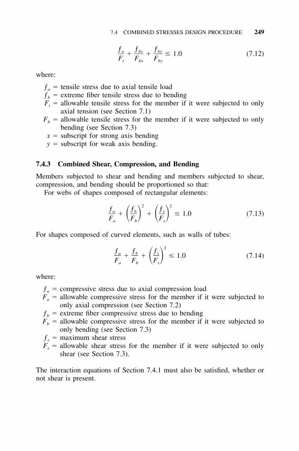
7.4 COMBINED STRESSES DESIGN PROCEDURE 249
ƒ ƒ ƒa bx by� � � 1.0 (7.12)F F Ft bx by
where:
ƒa � tensile stress due to axial tensile loadƒb � extreme fiber tensile stress due to bendingFt � allowable tensile stress for the member if it were subjected to only
axial tension (see Section 7.1)Fb � allowable tensile stress for the member if it were subjected to only
bending (see Section 7.3)x � subscript for strong axis bendingy � subscript for weak axis bending.
7.4.3 Combined Shear, Compression, and Bending
Members subjected to shear and bending and members subjected to shear,compression, and bending should be proportioned so that:
For webs of shapes composed of rectangular elements:
2 2ƒ ƒ ƒa b s� � � 1.0 (7.13)� � � �F F Fa b s
For shapes composed of curved elements, such as walls of tubes:
2ƒ ƒ ƒa b s� � � 1.0 (7.14)� �F F Fa b s
where:
ƒa � compressive stress due to axial compression loadFa � allowable compressive stress for the member if it were subjected to
only axial compression (see Section 7.2)ƒb � extreme fiber compressive stress due to bendingFb � allowable compressive stress for the member if it were subjected to
only bending (see Section 7.3)ƒs � maximum shear stressFs � allowable shear stress for the member if it were subjected to only
shear (see Section 7.3).
The interaction equations of Section 7.4.1 must also be satisfied, whether ornot shear is present.

251
8 Connections
Just when you were starting to get the hang of aluminum structural design,having sized a few members, you realize you have yet to figure out how toconnect them. What kind of fasteners are used for aluminum, and what aretheir design strengths? Can’t we just avoid the issue and call for all joints tobe full penetration welds and be done with it?
Not so fast. After all, airplanes that log 50 years of service don’t havewelded frames. We’ll consider the benefits and disadvantages of mechanicaland welded connections in aluminum and offer some guidelines for their uses.Both aluminum bolting and welding differ from their counterparts in steel,which we’ll explain.
We won’t discuss the third alternative, adhesives, even though adhesivesare used in a number of aluminum applications. Adhesives are not commonlyused for primary structural connections in construction, and standards for theirstructural design have not yet been developed. Silicone, polysulfide, and othersealants can adhere well to aluminum, however, and should be considered inplace of nonstructural seal welds when it is desirable to keep air or moistureout of joints.
Connections are critical to the integrity of structures, but they tend to bethe most imperfectly analyzed component. Also, failure at a connection ismore catastrophic than some other failure modes, such as local buckling.Consequently, metal design specifications require greater reliability for con-nections. This translates into higher factors of safety (20% higher in allowablestress design) and lower resistance factors (in load and resistance factor design[LRFD]) for connections than for members. This is summarized in Table 8.1.No safety margin is given for yielding of connections because such yieldingisn’t considered a limit state.
8.1 MECHANICAL CONNECTIONS
8.1.1 Introduction
Mechanical connections are the most reliable way to join aluminum structuralmembers, so we’ll begin with them. The mechanically fastened joints we’lldiscuss include those that are connected with rivets, bolts, pins, or screws.Rules for these joints are given in Section 5 of the Aluminum Specification.
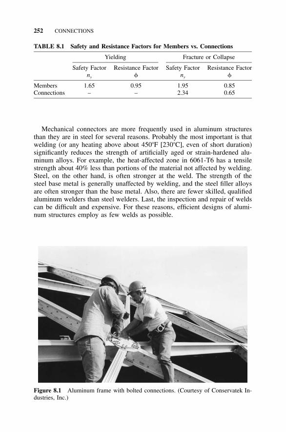
252 CONNECTIONS
TABLE 8.1 Safety and Resistance Factors for Members vs. Connections
Yielding
Safety Factorny
Resistance Factor
Fracture or Collapse
Safety Factorny
Resistance Factor
Members 1.65 0.95 1.95 0.85Connections – – 2.34 0.65
Figure 8.1 Aluminum frame with bolted connections. (Courtesy of Conservatek In-dustries, Inc.)
Mechanical connectors are more frequently used in aluminum structuresthan they are in steel for several reasons. Probably the most important is thatwelding (or any heating above about 450�F [230�C], even of short duration)significantly reduces the strength of artificially aged or strain-hardened alu-minum alloys. For example, the heat-affected zone in 6061-T6 has a tensilestrength about 40% less than portions of the material not affected by welding.Steel, on the other hand, is often stronger at the weld. The strength of thesteel base metal is generally unaffected by welding, and the steel filler alloysare often stronger than the base metal. Also, there are fewer skilled, qualifiedaluminum welders than steel welders. Last, the inspection and repair of weldscan be difficult and expensive. For these reasons, efficient designs of alumi-num structures employ as few welds as possible.
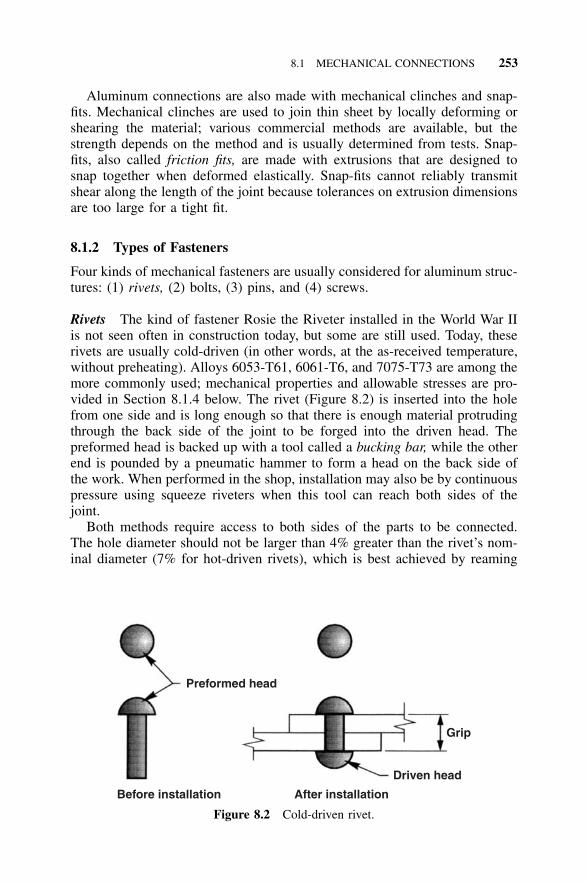
8.1 MECHANICAL CONNECTIONS 253
Preformed head
Before installation After installation
Driven head
Grip
Figure 8.2 Cold-driven rivet.
Aluminum connections are also made with mechanical clinches and snap-fits. Mechanical clinches are used to join thin sheet by locally deforming orshearing the material; various commercial methods are available, but thestrength depends on the method and is usually determined from tests. Snap-fits, also called friction fits, are made with extrusions that are designed tosnap together when deformed elastically. Snap-fits cannot reliably transmitshear along the length of the joint because tolerances on extrusion dimensionsare too large for a tight fit.
8.1.2 Types of Fasteners
Four kinds of mechanical fasteners are usually considered for aluminum struc-tures: (1) rivets, (2) bolts, (3) pins, and (4) screws.
Rivets The kind of fastener Rosie the Riveter installed in the World War IIis not seen often in construction today, but some are still used. Today, theserivets are usually cold-driven (in other words, at the as-received temperature,without preheating). Alloys 6053-T61, 6061-T6, and 7075-T73 are among themore commonly used; mechanical properties and allowable stresses are pro-vided in Section 8.1.4 below. The rivet (Figure 8.2) is inserted into the holefrom one side and is long enough so that there is enough material protrudingthrough the back side of the joint to be forged into the driven head. Thepreformed head is backed up with a tool called a bucking bar, while the otherend is pounded by a pneumatic hammer to form a head on the back side ofthe work. When performed in the shop, installation may also be by continuouspressure using squeeze riveters when this tool can reach both sides of thejoint.
Both methods require access to both sides of the parts to be connected.The hole diameter should not be larger than 4% greater than the rivet’s nom-inal diameter (7% for hot-driven rivets), which is best achieved by reaming
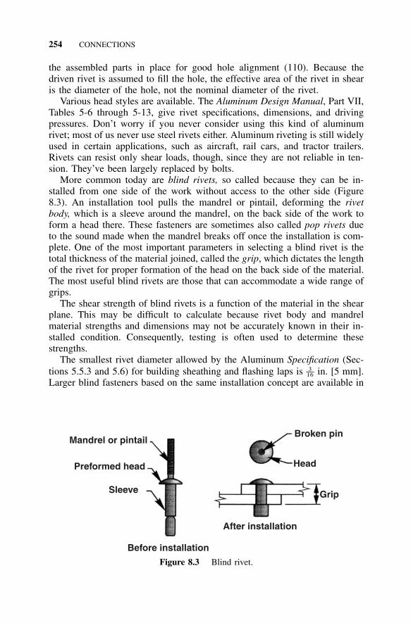
254 CONNECTIONS
Broken pin
Head
Grip
After installation
Before installation
Mandrel or pintail
Preformed head
Sleeve
Figure 8.3 Blind rivet.
the assembled parts in place for good hole alignment (110). Because thedriven rivet is assumed to fill the hole, the effective area of the rivet in shearis the diameter of the hole, not the nominal diameter of the rivet.
Various head styles are available. The Aluminum Design Manual, Part VII,Tables 5-6 through 5-13, give rivet specifications, dimensions, and drivingpressures. Don’t worry if you never consider using this kind of aluminumrivet; most of us never use steel rivets either. Aluminum riveting is still widelyused in certain applications, such as aircraft, rail cars, and tractor trailers.Rivets can resist only shear loads, though, since they are not reliable in ten-sion. They’ve been largely replaced by bolts.
More common today are blind rivets, so called because they can be in-stalled from one side of the work without access to the other side (Figure8.3). An installation tool pulls the mandrel or pintail, deforming the rivetbody, which is a sleeve around the mandrel, on the back side of the work toform a head there. These fasteners are sometimes also called pop rivets dueto the sound made when the mandrel breaks off once the installation is com-plete. One of the most important parameters in selecting a blind rivet is thetotal thickness of the material joined, called the grip, which dictates the lengthof the rivet for proper formation of the head on the back side of the material.The most useful blind rivets are those that can accommodate a wide range ofgrips.
The shear strength of blind rivets is a function of the material in the shearplane. This may be difficult to calculate because rivet body and mandrelmaterial strengths and dimensions may not be accurately known in their in-stalled condition. Consequently, testing is often used to determine thesestrengths.
The smallest rivet diameter allowed by the Aluminum Specification (Sec-tions 5.5.3 and 5.6) for building sheathing and flashing laps is in. [5 mm].3––16
Larger blind fasteners based on the same installation concept are available in
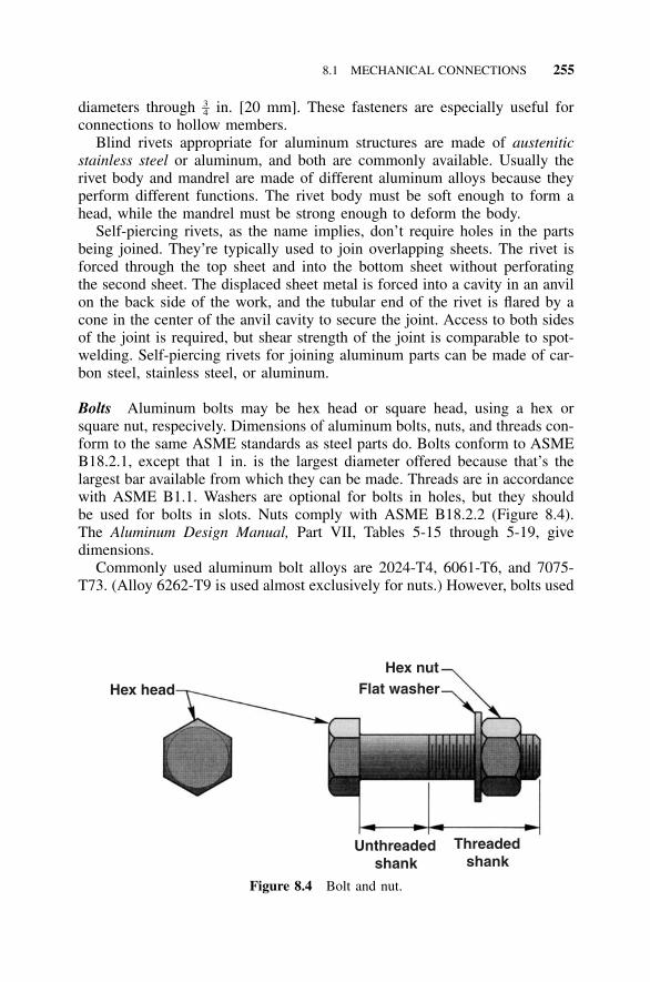
8.1 MECHANICAL CONNECTIONS 255
Hex head
Hex nutFlat washer
Unthreaded shank
Threaded shank
Figure 8.4 Bolt and nut.
diameters through in. [20 mm]. These fasteners are especially useful for3–4connections to hollow members.
Blind rivets appropriate for aluminum structures are made of austeniticstainless steel or aluminum, and both are commonly available. Usually therivet body and mandrel are made of different aluminum alloys because theyperform different functions. The rivet body must be soft enough to form ahead, while the mandrel must be strong enough to deform the body.
Self-piercing rivets, as the name implies, don’t require holes in the partsbeing joined. They’re typically used to join overlapping sheets. The rivet isforced through the top sheet and into the bottom sheet without perforatingthe second sheet. The displaced sheet metal is forced into a cavity in an anvilon the back side of the work, and the tubular end of the rivet is flared by acone in the center of the anvil cavity to secure the joint. Access to both sidesof the joint is required, but shear strength of the joint is comparable to spot-welding. Self-piercing rivets for joining aluminum parts can be made of car-bon steel, stainless steel, or aluminum.
Bolts Aluminum bolts may be hex head or square head, using a hex orsquare nut, respecively. Dimensions of aluminum bolts, nuts, and threads con-form to the same ASME standards as steel parts do. Bolts conform to ASMEB18.2.1, except that 1 in. is the largest diameter offered because that’s thelargest bar available from which they can be made. Threads are in accordancewith ASME B1.1. Washers are optional for bolts in holes, but they shouldbe used for bolts in slots. Nuts comply with ASME B18.2.2 (Figure 8.4).The Aluminum Design Manual, Part VII, Tables 5-15 through 5-19, givedimensions.
Commonly used aluminum bolt alloys are 2024-T4, 6061-T6, and 7075-T73. (Alloy 6262-T9 is used almost exclusively for nuts.) However, bolts used
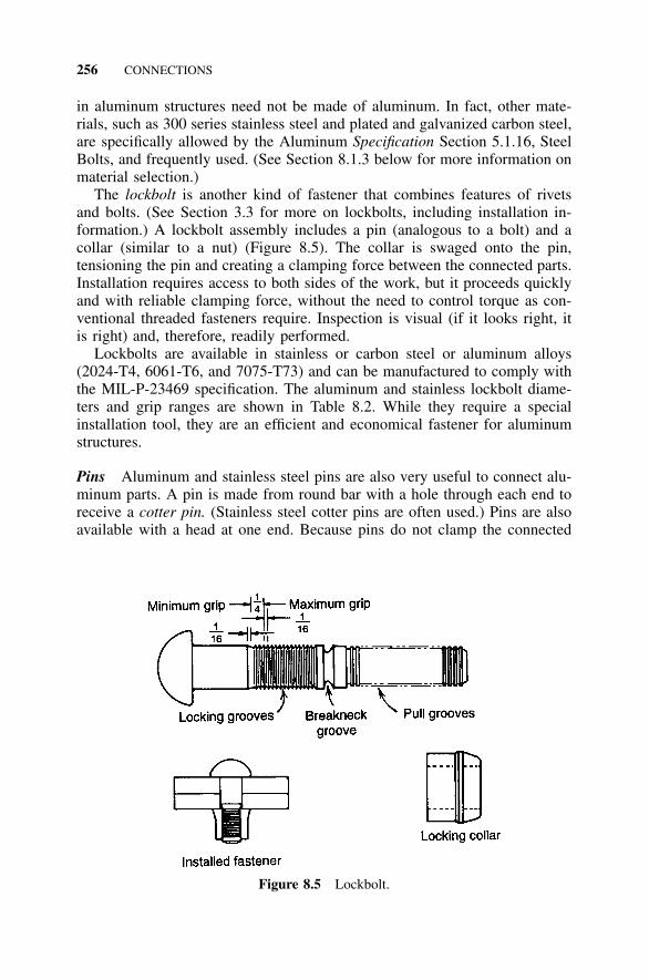
256 CONNECTIONS
Figure 8.5 Lockbolt.
in aluminum structures need not be made of aluminum. In fact, other mate-rials, such as 300 series stainless steel and plated and galvanized carbon steel,are specifically allowed by the Aluminum Specification Section 5.1.16, SteelBolts, and frequently used. (See Section 8.1.3 below for more information onmaterial selection.)
The lockbolt is another kind of fastener that combines features of rivetsand bolts. (See Section 3.3 for more on lockbolts, including installation in-formation.) A lockbolt assembly includes a pin (analogous to a bolt) and acollar (similar to a nut) (Figure 8.5). The collar is swaged onto the pin,tensioning the pin and creating a clamping force between the connected parts.Installation requires access to both sides of the work, but it proceeds quicklyand with reliable clamping force, without the need to control torque as con-ventional threaded fasteners require. Inspection is visual (if it looks right, itis right) and, therefore, readily performed.
Lockbolts are available in stainless or carbon steel or aluminum alloys(2024-T4, 6061-T6, and 7075-T73) and can be manufactured to comply withthe MIL-P-23469 specification. The aluminum and stainless lockbolt diame-ters and grip ranges are shown in Table 8.2. While they require a specialinstallation tool, they are an efficient and economical fastener for aluminumstructures.
Pins Aluminum and stainless steel pins are also very useful to connect alu-minum parts. A pin is made from round bar with a hole through each end toreceive a cotter pin. (Stainless steel cotter pins are often used.) Pins are alsoavailable with a head at one end. Because pins do not clamp the connected
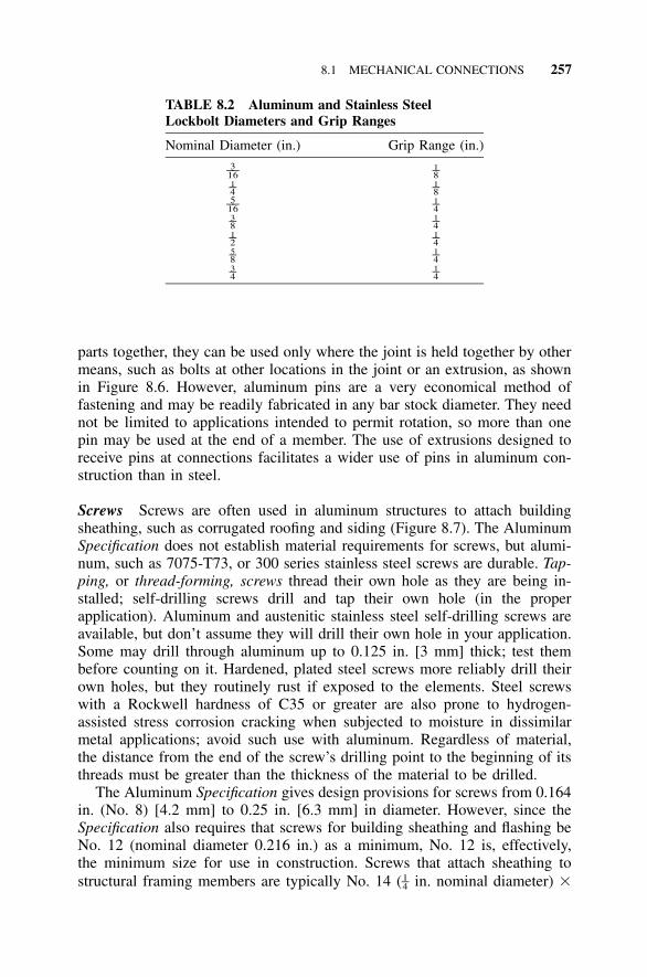
8.1 MECHANICAL CONNECTIONS 257
TABLE 8.2 Aluminum and Stainless SteelLockbolt Diameters and Grip Ranges
Nominal Diameter (in.) Grip Range (in.)3––16
1–81–4 1–85––16
1–43–8 1–41–2 1–45–8 1–43–4 1–4
parts together, they can be used only where the joint is held together by othermeans, such as bolts at other locations in the joint or an extrusion, as shownin Figure 8.6. However, aluminum pins are a very economical method offastening and may be readily fabricated in any bar stock diameter. They neednot be limited to applications intended to permit rotation, so more than onepin may be used at the end of a member. The use of extrusions designed toreceive pins at connections facilitates a wider use of pins in aluminum con-struction than in steel.
Screws Screws are often used in aluminum structures to attach buildingsheathing, such as corrugated roofing and siding (Figure 8.7). The AluminumSpecification does not establish material requirements for screws, but alumi-num, such as 7075-T73, or 300 series stainless steel screws are durable. Tap-ping, or thread-forming, screws thread their own hole as they are being in-stalled; self-drilling screws drill and tap their own hole (in the properapplication). Aluminum and austenitic stainless steel self-drilling screws areavailable, but don’t assume they will drill their own hole in your application.Some may drill through aluminum up to 0.125 in. [3 mm] thick; test thembefore counting on it. Hardened, plated steel screws more reliably drill theirown holes, but they routinely rust if exposed to the elements. Steel screwswith a Rockwell hardness of C35 or greater are also prone to hydrogen-assisted stress corrosion cracking when subjected to moisture in dissimilarmetal applications; avoid such use with aluminum. Regardless of material,the distance from the end of the screw’s drilling point to the beginning of itsthreads must be greater than the thickness of the material to be drilled.
The Aluminum Specification gives design provisions for screws from 0.164in. (No. 8) [4.2 mm] to 0.25 in. [6.3 mm] in diameter. However, since theSpecification also requires that screws for building sheathing and flashing beNo. 12 (nominal diameter 0.216 in.) as a minimum, No. 12 is, effectively,the minimum size for use in construction. Screws that attach sheathing tostructural framing members are typically No. 14 ( in. nominal diameter) �1–4
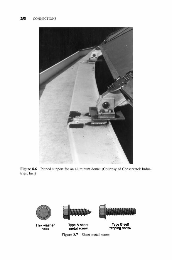
258 CONNECTIONS
Figure 8.6 Pinned support for an aluminum dome. (Courtesy of Conservatek Indus-tries, Inc.)
Figure 8.7 Sheet metal screw.
8.1 MECHANICAL CONNECTIONS 259
1 in. long type B 300 series stainless steel tapping screws. Screws used tojoin roofing or siding sheets to each other at laps are typically No. 14 � 3–4in. long type A 300 series stainless steel sheet-metal screws. The type A andtype B designations are for types of points and threads most suitable for theseapplications and both require a predrilled hole. Section 10.1 contains moreinformation on screws for building sheathing.
Washers—either part of the head or separate—are used under the screwhead to decrease the likelihood of failure under tensile load by means of thesheet pulling over the head of the screw (see Section 8.1.17 below). Metalwashers with neoprene gaskets (called combination washers) also seal thejoint against leakage and are effective on properly driven screws.
Aluminum nails are also available. Aluminum nails produced to ASTMF1667, Driven Fasteners: Nails, Spikes, and Staples, are made of 2024, 5056,6061, or 6110 alloy and all have a minimum tensile strength of 60 ksi [415MPa].
Dimensions and other information about many fasteners are available fromthe Industrial Fastener Institute (IFI) publication Fastener Standards (in bothEnglish and metric unit versions). A great variety of other types of fasteners,such as turnbuckles, clevises, and eyebolts, are available in materials suitablefor use in aluminum structures, including, in many cases, aluminum and 300series stainless steel. Availability is a function of quality, quantity, and leadtime, so you’ll have to consult fastener suppliers.
8.1.3 Fastener Material Selection
In steel design, engineers usually give little consideration to fastener material:steel fasteners are used in steel structures. In aluminum, the choice is lessobvious. This is probably because more options exist, as well as becausealuminum structures are often provided without protective coatings and incorrosive environments unsuitable for steel alloys. Corrosion of fasteners is acritical concern since fasteners are much smaller than the material they join.Corrosion of fasteners tends to result in a greater decrease in the strength ofthe structure than the same depth of corrosion in a larger member.
When different materials are used for fasteners and the members they join,galvanic corrosion may occur. Different materials, even different alloys ofaluminum, have different electrical potential, and in the presence of an elec-trolyte, such as a wet industrial atmosphere, electric current flows from onematerial to another. This current tends to corrode the anode and protect thecathode—the principle used in cathodic protection. The greater the differencein electrical potential, the more severe the corrosion; conversely, you canprevent galvanic corrosion by using a fastener with about the same electricalpotential as the base metal. Galvanic corrosion can also be thwarted if therelative surface area of the anode is much larger than that of the cathode,which is the case when the fastener is the cathode. There is also the issue ofthe corrosion resistance of the fastener itself in the service environment, in-
260 CONNECTIONS
dependent of the metal being joined. In light of these considerations, here’show the various materials stack up for use in connecting aluminum parts:
Aluminum Fasteners Higher strength aluminum alloys 2024 and 7075 areless corrosion resistant than 6061, but they are acceptable for most applica-tions. Sometimes, higher strength alloys are anodized for additional protec-tion. Aluminum Specification Section 5.1 specifies a 0.2 mil [0.005 mm] thickanodized coating for 2024 bolts when specified by the designer, and it’s agood idea to do so if they will be exposed to moisture. Because the electrical-potential difference between aluminum alloys is small, aluminum bolts don’tsuffer significant galvanic corrosion when used in aluminum members. Thefull list of aluminum alloys produced in wire and rod suitable for manufac-turing fasteners is given in Table 8.4.
Stainless Steel Fasteners Whoever came up with the name ‘‘stainless steel’’was a marketing genius—the alliteration and the image it conjures up aremasterful. The problem is, stainless steel stains sometimes. While it’s is oftenreferred to as if it were one material, the American Iron and Steel Institute(AISI) actually recognizes dozens of stainless steel alloys. Furthermore, mostalloys are available in different conditions that have different strengths. Threebroad categories of stainless steel exist. From lowest to highest regardingcorrosion resistance, they are: martensitic, ferritic, and austenitic; about allthey have in common is that they all have at least 10.5% chromium. Chro-mium is what differentiates stainless steel from rust; nickel helps, too, andboth are the reason stainless steel is so much more expensive than plain steel.Carbon increases strength, but it decreases the corrosion resistance effect ofchromium.
The martensitic stainless steels, the least corrosion resistant of the group,are iron-chromium alloys with 12% to 17% chromium. They also have enoughcarbon to be heat-treatable, so they can be provided in high strengths, butthat’s also why they aren’t very corrosion resistant. Type 410 is a popularexample; with only 12.5% nominal chromium content, it’s one of the leastexpensive stainless steels. The ferritic stainless steels are also iron-chromiumalloys, but without carbon. They are not heat-treatable, so they don’t comein high strengths. Type 430 is the most popular ferritic stainless steel alloy;it has a nominal chromium content of 16%. The austenitic stainless steels(200 and 300 series) have about 18% chromium and 8% nickel; as such, theyare very corrosion resistant. They’re not heat-treatable, but they are strength-ened by cold-working.
The austenitic stainless steels are the most suitable for use with aluminumand constitute about 80% of all stainless steel fasteners made. If you don’tspecify which austenitic stainless steel alloy you require, so-called 18-8 istypically furnished. A number of alloys fit this description, so any one ofthem might be supplied. For example, type 303 is among the least expensiveand machines well, but it has the lowest corrosion resistance among the 300
8.1 MECHANICAL CONNECTIONS 261
series stainless alloys. Type 304 is more corrosion resistant, and type 316 isbetter still (at a 50% cost premium), especially in marine environments.Which alloy do you suppose will be supplied on your job if you don’t specifyone?
The point is that you should specify exactly which alloy you want. Type304 works well in most industrial atmospheres; the corrosion resistance oftype 316 in marine environments can justify its cost premium. Any materialsubmerged in liquid should be subject to special investigation and then testedin that environment. Once the alloy is selected, its condition, which estab-lishes its strength, should be chosen. We’ll discuss this further under the topicof fastener strengths below.
It’s only a matter of time before plated steel and ferritic and martensiticstainless steel screws rust when exposed to the elements. The heads ofthrough-fastened screws used to attach the cladding of a structure are exposedto the weather, so they rust right out there for everyone to see. Fortunately,plated steel and ferritic and martensitic stainless steels are magnetic, whilethe preferred aluminum and austenitic stainless steel screws are not. Thus, amagnet offers an easy way to identify an offending fastener. For locations notexposed to the elements, the proposed North American Fenestration standard,which is similar to AAMA/NWWDA 101, allows the use of both non-austenitic stainless steel with a nominal content of 16% or more chromiumand coated carbon steel fasteners. This allows 430 stainless but excludes 410stainless.
Carbon Steel Fasteners Plated or galvanized carbon steel bolts may be use-ful in less exposed or corrosive applications. Coated A307 and A325 boltsmay be used, but A490 bolts are not allowed by the Aluminum Specificationbecause they become brittle when galvanized (122). This is no great loss,however, since A490 bolts are most profitably used with high strength steelmembers, and aluminum alloy strengths this high are not generally used inconstruction. Because A449 bolts have less stringent quality control provi-sions than A325 bolts, A449 bolts are permitted only by the Steel Specifi-cation (38, 39) for diameters not available in A325, which is above 1 in.1–2diameter. Bolts of this size are not often needed in either steel buildings oraluminum construction. Steel rivets are prohibited by the Aluminum Specifi-cation unless corrosion is of no concern.
8.1.4 Fastener Mechanical Properties
The minimum mechanical properties of concern (shear and tensile ultimatestrengths) for aluminum bolts are listed in Aluminum Specification Table5.1.1.1-1. Specifications for aluminum bolts are also contained in ASTMF468, Nonferrous Bolts, Hex Cap Screws, and Studs for General Use (80);and in ASTM F467, Nonferrous Nuts for General Use (79), for aluminumnuts. (However, see the clarifying note below in the paragraph regarding ten-
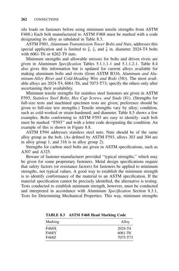
262 CONNECTIONS
TABLE 8.3 ASTM F468 Head Marking Code
Marking Alloy
F468X 2024-T4F468Y 6061-T6F468Z 7075-T73
sile loads on fasteners before using minimum tensile strengths from ASTMF468.) Each bolt manufactured to ASTM F468 must be marked with a codedesignating its alloy as tabulated in Table 8.3.
ASTM F901, Aluminum Transmission Tower Bolts and Nuts, addresses thisspecial application and is limited to , , and in. diameter 2024-T4 bolts5 3 7– – –8 4 8
with 6061-T6 or 6262-T9 nuts.Minimum strengths and allowable stresses for bolts and driven rivets are
given in Aluminum Specification Tables 5.1.1.1-1 and 5.1.1.2-1. Table 8.4also gives this information but is updated for current alloys available formaking aluminum bolts and rivets (from ASTM B316, Aluminum and Alu-minum-Alloy Rivet and Cold-Heading Wire and Rods (58)). The most avail-able alloys are 2024-T4, 6061-T6, and 7073-T73; specify the others only afterascertaining their availability.
Minimum tensile strengths for stainless steel fasteners are given in ASTMF593, Stainless Steel Bolts, Hex Cap Screws, and Studs (81). (Strengths forfull-size tests and machined specimen tests are given; preference should begiven to full-size test strengths.) Tensile strengths vary by alloy; condition,such as cold-worked or strain-hardened; and diameter. Table 8.5 shows a fewexamples. Bolts conforming to ASTM F593 are easy to identify: each boltmust be marked ‘‘F593’’ and with a letter code designating the condition. Anexample of this is shown in Figure 8.8.
ASTM F594 addresses stainless steel nuts. Nuts should be of the samealloy group as the bolt. (As defined by ASTM F593, alloys 303 and 304 arein alloy group 1, and 316 is in alloy group 2).
Strengths for carbon steel bolts are given in ASTM specifications, such asA307 and A325.
Beware of fastener-manufacturer provided ‘‘typical strengths,’’ which maybe given for some proprietary fasteners. Metal design specifications requirethat safety factors (or resistance factors) for fasteners be applied to minimumstrengths, not typical values. A good way to establish the minimum strengthis to identify conformance of the material to an ASTM specification. If thematerial specification cannot be precisely identified, the alternative is testing.Tests conducted to establish minimum strength, however, must be conductedand interpreted in accordance with Aluminum Specification Section 8.3.1,Tests for Determining Mechanical Properties. This way, minimum strengths
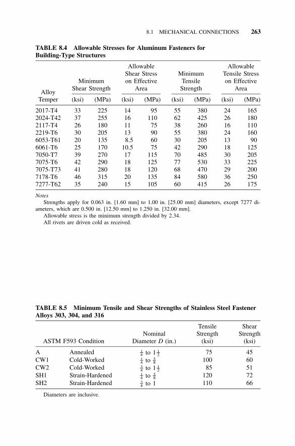
8.1 MECHANICAL CONNECTIONS 263
TABLE 8.4 Allowable Stresses for Aluminum Fasteners forBuilding-Type Structures
AlloyTemper
MinimumShear Strength
(ksi) (MPa)
AllowableShear Stresson Effective
Area
(ksi) (MPa)
MinimumTensile
Strength
(ksi) (MPa)
AllowableTensile Stresson Effective
Area
(ksi) (MPa)
2017-T4 33 225 14 95 55 380 24 1652024-T42 37 255 16 110 62 425 26 1802117-T4 26 180 11 75 38 260 16 1102219-T6 30 205 13 90 55 380 24 1606053-T61 20 135 8.5 60 30 205 13 906061-T6 25 170 10.5 75 42 290 18 1257050-T7 39 270 17 115 70 485 30 2057075-T6 42 290 18 125 77 530 33 2257075-T73 41 280 18 120 68 470 29 2007178-T6 46 315 20 135 84 580 36 2507277-T62 35 240 15 105 60 415 26 175
NotesStrengths apply for 0.063 in. [1.60 mm] to 1.00 in. [25.00 mm] diameters, except 7277 di-
ameters, which are 0.500 in. [12.50 mm] to 1.250 in. [32.00 mm].Allowable stress is the minimum strength divided by 2.34.All rivets are driven cold as received.
TABLE 8.5 Minimum Tensile and Shear Strengths of Stainless Steel FastenerAlloys 303, 304, and 316
ASTM F593 ConditionNominal
Diameter D (in.)
TensileStrength
(ksi)
ShearStrength
(ksi)
A Annealed to 11 1– –4 2 75 45CW1 Cold-Worked to1 5– –4 8 100 60CW2 Cold-Worked to 13 1– –4 2 85 51SH1 Strain-Hardened to1 5– –4 8 120 72SH2 Strain-Hardened to 13–4 110 66
Diameters are inclusive.
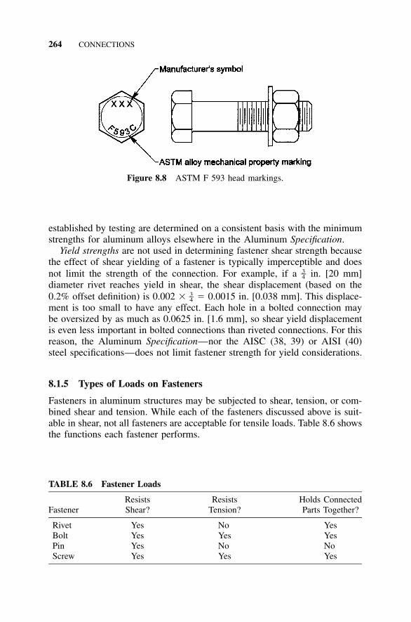
264 CONNECTIONS
Figure 8.8 ASTM F 593 head markings.
TABLE 8.6 Fastener Loads
FastenerResistsShear?
ResistsTension?
Holds ConnectedParts Together?
Rivet Yes No YesBolt Yes Yes YesPin Yes No NoScrew Yes Yes Yes
established by testing are determined on a consistent basis with the minimumstrengths for aluminum alloys elsewhere in the Aluminum Specification.
Yield strengths are not used in determining fastener shear strength becausethe effect of shear yielding of a fastener is typically imperceptible and doesnot limit the strength of the connection. For example, if a in. [20 mm]3–4diameter rivet reaches yield in shear, the shear displacement (based on the0.2% offset definition) is 0.002 � � 0.0015 in. [0.038 mm]. This displace-3–4ment is too small to have any effect. Each hole in a bolted connection maybe oversized by as much as 0.0625 in. [1.6 mm], so shear yield displacementis even less important in bolted connections than riveted connections. For thisreason, the Aluminum Specification—nor the AISC (38, 39) or AISI (40)steel specifications—does not limit fastener strength for yield considerations.
8.1.5 Types of Loads on Fasteners
Fasteners in aluminum structures may be subjected to shear, tension, or com-bined shear and tension. While each of the fasteners discussed above is suit-able in shear, not all fasteners are acceptable for tensile loads. Table 8.6 showsthe functions each fastener performs.
8.1 MECHANICAL CONNECTIONS 265
8.1.6 Types of Bolted Connections
Rivets were the first kind of fastener devised for both steel and aluminumstructures. They were labor-intensive to install and tolerated almost no holemismatch, but were simple and permanent. Another drawback, though, wasthat they were unsuitable for any appreciable tensile loads. Bolts, too, wereunreliable under cyclic tensile loads because the nuts could loosen, and sowere confined to temporary use during erection. The introduction of high-strength steel bolts in the 1950s overcame this problem in steel construction.They were strong enough to be tightened sufficiently that there was no dangerof the nuts coming off. These bolts could, if needed, use friction between thefaying surfaces to prevent the connected parts from slipping in relation toeach other, although at a reduced design strength. In the AISC Steel Speci-fication (38, 39), the connections designed for no slippage are called slip-critical connections (formerly called friction connections).
Aluminum Friction Connections Friction connections (or slip-critical con-nections; call them what you will), however, are a much more recent devel-opment in aluminum structures, being introduced to the Aluminum Specifi-cation in Section 5.1.17 only in 2000. Even so, the circumstances under whichthey can be used are relatively limited: the aluminum faying surfaces mustbe abrasion-blasted with coal slag to an average substrate profile of 2.0 mils[0.05 mm], for which a slip coefficient of 0.50 is given (121). Such aluminumsurfaces may be used in contact with similarly treated aluminum surfaces ora steel surface with a 4 mil [0.1 mm] maximum thickness zinc-rich paint.Only zinc-coated A325 bolts may be used; this is to prevent galvanic corro-sion between the steel bolt and the aluminum parts. The connected aluminumparts must have a tensile yield strength of at least 15 ksi [105 MPa] to keepthe bolt from crushing the connected parts. Given these limitations and thefact that the smallest A325 bolt diameter is in. (and in. is much more1 3– –2 4
common), aluminum slip-critical connections are only for the stronger alu-minum alloys in heavy duty structural uses.
Because aluminum and steel have different coefficients of thermal expan-sion, some have speculated that aluminum friction connections could loosenif the temperature changed from the installation temperature. For example, ifthe temperature drops after tightening, the aluminum parts in the grip of thebolt should contract more than the steel bolt. This could cause relaxation ofthe bolt tension. Logical as this sounds, tests conducted in the U.S. and Can-ada (104, 123) have not been able to consistently demonstrate such an effect,and no one has been able to explain why.
Tests (124) were also conducted to determine the proper turn-of-nut tight-ening method for aluminum friction connections. Since aluminum has a lowermodulus of elasticity than steel, investigators expected it might take moreturns to achieve the same bolt tension with aluminum parts in the bolt gripversus steel parts. In the tests, however, it took nearly identical turns after the
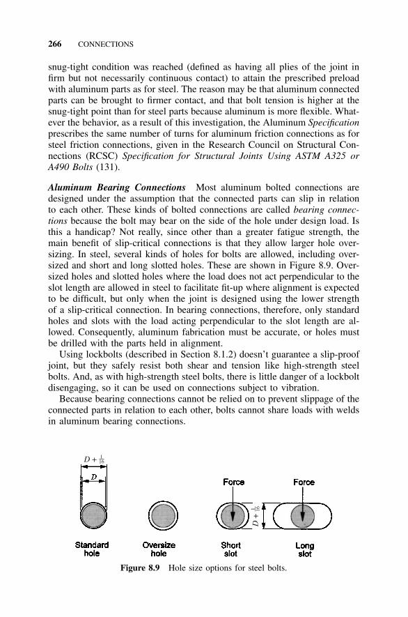
266 CONNECTIONS
D + 116
D +
1 16
Figure 8.9 Hole size options for steel bolts.
snug-tight condition was reached (defined as having all plies of the joint infirm but not necessarily continuous contact) to attain the prescribed preloadwith aluminum parts as for steel. The reason may be that aluminum connectedparts can be brought to firmer contact, and that bolt tension is higher at thesnug-tight point than for steel parts because aluminum is more flexible. What-ever the behavior, as a result of this investigation, the Aluminum Specificationprescribes the same number of turns for aluminum friction connections as forsteel friction connections, given in the Research Council on Structural Con-nections (RCSC) Specification for Structural Joints Using ASTM A325 orA490 Bolts (131).
Aluminum Bearing Connections Most aluminum bolted connections aredesigned under the assumption that the connected parts can slip in relationto each other. These kinds of bolted connections are called bearing connec-tions because the bolt may bear on the side of the hole under design load. Isthis a handicap? Not really, since other than a greater fatigue strength, themain benefit of slip-critical connections is that they allow larger hole over-sizing. In steel, several kinds of holes for bolts are allowed, including over-sized and short and long slotted holes. These are shown in Figure 8.9. Over-sized holes and slotted holes where the load does not act perpendicular to theslot length are allowed in steel to facilitate fit-up where alignment is expectedto be difficult, but only when the joint is designed using the lower strengthof a slip-critical connection. In bearing connections, therefore, only standardholes and slots with the load acting perpendicular to the slot length are al-lowed. Consequently, aluminum fabrication must be accurate, or holes mustbe drilled with the parts held in alignment.
Using lockbolts (described in Section 8.1.2) doesn’t guarantee a slip-proofjoint, but they safely resist both shear and tension like high-strength steelbolts. And, as with high-strength steel bolts, there is little danger of a lockboltdisengaging, so it can be used on connections subject to vibration.
Because bearing connections cannot be relied on to prevent slippage of theconnected parts in relation to each other, bolts cannot share loads with weldsin aluminum bearing connections.
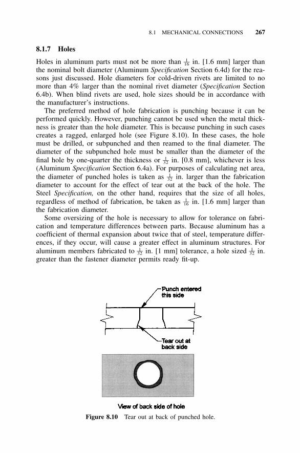
8.1 MECHANICAL CONNECTIONS 267
Figure 8.10 Tear out at back of punched hole.
8.1.7 Holes
Holes in aluminum parts must not be more than in. [1.6 mm] larger than1––16
the nominal bolt diameter (Aluminum Specification Section 6.4d) for the rea-sons just discussed. Hole diameters for cold-driven rivets are limited to nomore than 4% larger than the nominal rivet diameter (Specification Section6.4b). When blind rivets are used, hole sizes should be in accordance withthe manufacturer’s instructions.
The preferred method of hole fabrication is punching because it can beperformed quickly. However, punching cannot be used when the metal thick-ness is greater than the hole diameter. This is because punching in such casescreates a ragged, enlarged hole (see Figure 8.10). In these cases, the holemust be drilled, or subpunched and then reamed to the final diameter. Thediameter of the subpunched hole must be smaller than the diameter of thefinal hole by one-quarter the thickness or in. [0.8 mm], whichever is less1––32
(Aluminum Specification Section 6.4a). For purposes of calculating net area,the diameter of punched holes is taken as in. larger than the fabrication1––32
diameter to account for the effect of tear out at the back of the hole. TheSteel Specification, on the other hand, requires that the size of all holes,regardless of method of fabrication, be taken as in. [1.6 mm] larger than1––16
the fabrication diameter.Some oversizing of the hole is necessary to allow for tolerance on fabri-
cation and temperature differences between parts. Because aluminum has acoefficient of thermal expansion about twice that of steel, temperature differ-ences, if they occur, will cause a greater effect in aluminum structures. Foraluminum members fabricated to in. [1 mm] tolerance, a hole sized in.1 1–– ––32 32
greater than the fastener diameter permits ready fit-up.
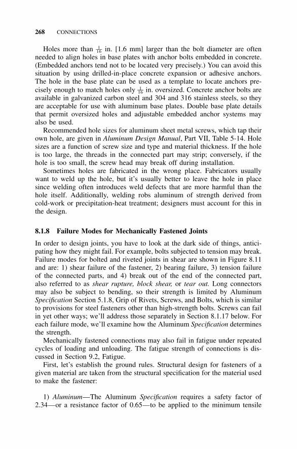
268 CONNECTIONS
Holes more than in. [1.6 mm] larger than the bolt diameter are often1––16
needed to align holes in base plates with anchor bolts embedded in concrete.(Embedded anchors tend not to be located very precisely.) You can avoid thissituation by using drilled-in-place concrete expansion or adhesive anchors.The hole in the base plate can be used as a template to locate anchors pre-cisely enough to match holes only in. oversized. Concrete anchor bolts are1––16
available in galvanized carbon steel and 304 and 316 stainless steels, so theyare acceptable for use with aluminum base plates. Double base plate detailsthat permit oversized holes and adjustable embedded anchor systems mayalso be used.
Recommended hole sizes for aluminum sheet metal screws, which tap theirown hole, are given in Aluminum Design Manual, Part VII, Table 5-14. Holesizes are a function of screw size and type and material thickness. If the holeis too large, the threads in the connected part may strip; conversely, if thehole is too small, the screw head may break off during installation.
Sometimes holes are fabricated in the wrong place. Fabricators usuallywant to weld up the hole, but it’s usually better to leave the hole in placesince welding often introduces weld defects that are more harmful than thehole itself. Additionally, welding robs aluminum of strength derived fromcold-work or precipitation-heat treatment; designers must account for this inthe design.
8.1.8 Failure Modes for Mechanically Fastened Joints
In order to design joints, you have to look at the dark side of things, antici-pating how they might fail. For example, bolts subjected to tension may break.Failure modes for bolted and riveted joints in shear are shown in Figure 8.11and are: 1) shear failure of the fastener, 2) bearing failure, 3) tension failureof the connected parts, and 4) break out of the end of the connected part,also referred to as shear rupture, block shear, or tear out. Long connectorsmay also be subject to bending, so their strength is limited by AluminumSpecification Section 5.1.8, Grip of Rivets, Screws, and Bolts, which is similarto provisions for steel fasteners other than high-strength bolts. Screws can failin yet other ways; we’ll address those separately in Section 8.1.17 below. Foreach failure mode, we’ll examine how the Aluminum Specification determinesthe strength.
Mechanically fastened connections may also fail in fatigue under repeatedcycles of loading and unloading. The fatigue strength of connections is dis-cussed in Section 9.2, Fatigue.
First, let’s establish the ground rules. Structural design for fasteners of agiven material are taken from the structural specification for the material usedto make the fastener:
1) Aluminum—The Aluminum Specification requires a safety factor of2.34—or a resistance factor of 0.65—to be applied to the minimum tensile
8.1 MECHANICAL CONNECTIONS 269
Figure 8.11 Failure modes of bolted connections.
and shear ultimate strengths of aluminum bolts and rivets for building struc-tures. (See Specification Section 5.1.1.) For screws, a safety factor of 3.0, ora resistance factor of 0.50, is used.
2) Stainless Steel—ASCE 8-90, Specification for the Design of Cold-Formed Stainless Steel Structural Members (82), governs the design of stain-less steel fasteners used in aluminum structures. In that specification, TableE requires factors of safety on minimum strengths of 3.0 for bolt shear and3.0 for bolt tensile strength. (Minimum strengths are given in ASTM F593as discussed above.) Table 6 of ASCE 8-90 gives resistance factors if LRFDis used. Because stainless steel material specifications do not provide a min-imum shear strength (unlike the Aluminum Specification), ASCE 8-90 pro-vides the relationship that shear strength is 60% of tensile strength. (See itsSection 5.3.4 commentary.)
3) Carbon Steel—The AISC Specification for Structural Steel Buildingsgoverns the design of carbon steel bolts in buildings. Strengths for designmay be taken from Steel Specification Table J3.2, but only bearing connec-tions may be used unless the faying surfaces are prepared in accordance withAluminum Specification Section 5.1.17. As we discussed above, bearing con-nections have higher design strengths than slip-critical connections, so froma strength standpoint, this is not a disadvantage. The AAMA Metal CurtainWall Fasteners report (34) offers guidance on design of steel fasteners notincluded in the AISC Specification.
270 CONNECTIONS
8.1.9 Tensile Loads on Fasteners
Aluminum differs from steel when it comes to the definition of the effectivearea of a bolt in tension. For steel bolts, the tensile effective area is the tensilestress area:
20.9743tensile stress area � A � 0.7854 D �� �s n
where:
D � nominal size (basic major diameter)n � number of threads per in.
The tensile stress area is an empirically determined area used for comput-ing the tensile strength of externally threaded fasteners. It has been selectedso that when the fastener strength (in units of force) is divided by the tensilestress area (in units of area), the resulting calculated stress equals the tensilestrength of the material (in units of force per unit area). The diameter onwhich the tensile stress area is based is between the outside diameter of thefastener and the diameter at the root of the threads, and it accounts for thenotch and helix effect of the threads. Tensile stress areas are tabulated in theSteel Manual (39), page 4-147, for coarse threads, and the same equation isused for stainless steel fasteners and tabulated in ASTM F593, Table 4, forboth coarse and fine thread series. (Coarse threaded bolts are typically usedin construction.)
The effective area of aluminum bolts in tension is defined as the root areain Aluminum Specification Section 5.1.1.1. The root area is not defined inthe Specification, nor in the IFI Fastener Standards (112), but Fastener Stan-dards defines the root diameter as the non-preferred term for the minor di-ameter of external thread for which it defines the area as:
21.3A � 0.7854 D �� �r n
Comparing the equations for As and Ar, you can see that the area used tocalculate tensile stress on an aluminum bolt (Ar) is less than the area used tocalculate tensile stress area on a steel bolt (As). Table 8.7 gives effective tensileareas for coarse-thread series for steel and aluminum bolts. The effective areasused for steel are 10% to 18% greater than the effective tensile areas usedfor aluminum. There is no physical difference in size for bolts of the twomaterials; their definitions of effective tensile area are simply different. Be-cause ASTM F468 uses the steel definition for effective tensile area, minimumtensile strengths for aluminum alloys in ASTM F468 have been factored downto give the same tensile force as the Aluminum Specification when area ismultiplied by strength.
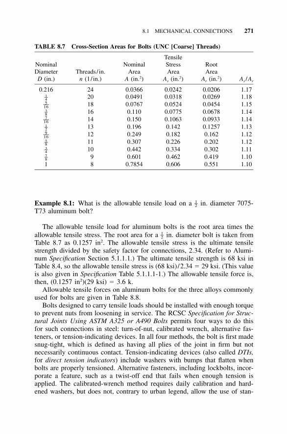
8.1 MECHANICAL CONNECTIONS 271
TABLE 8.7 Cross-Section Areas for Bolts (UNC [Coarse] Threads)
NominalDiameterD (in.)
Threads/ in.n (1 / in.)
NominalArea
A (in.2)
TensileStressArea
As (in.2)
RootArea
Ar (in.2) As /Ar
0.216 24 0.0366 0.0242 0.0206 1.171–4 20 0.0491 0.0318 0.0269 1.185––16 18 0.0767 0.0524 0.0454 1.153–8 16 0.110 0.0775 0.0678 1.147––16 14 0.150 0.1063 0.0933 1.141–2 13 0.196 0.142 0.1257 1.139––16 12 0.249 0.182 0.162 1.125–8 11 0.307 0.226 0.202 1.123–4 10 0.442 0.334 0.302 1.117–8 9 0.601 0.462 0.419 1.101 8 0.7854 0.606 0.551 1.10
Example 8.1: What is the allowable tensile load on a in. diameter 7075-1–2T73 aluminum bolt?
The allowable tensile load for aluminum bolts is the root area times theallowable tensile stress. The root area for a in. diameter bolt is taken from1–2Table 8.7 as 0.1257 in2. The allowable tensile stress is the ultimate tensilestrength divided by the safety factor for connections, 2.34. (Refer to Alumi-num Specification Section 5.1.1.1.) The ultimate tensile strength is 68 ksi inTable 8.4, so the allowable tensile stress is (68 ksi) /2.34 � 29 ksi. (This valueis also given in Specification Table 5.1.1.1-1.) The allowable tensile force is,then, (0.1257 in2)(29 ksi) � 3.6 k.
Allowable tensile forces on aluminum bolts for the three alloys commonlyused for bolts are given in Table 8.8.
Bolts designed to carry tensile loads should be installed with enough torqueto prevent nuts from loosening in service. The RCSC Specification for Struc-tural Joints Using ASTM A325 or A490 Bolts permits four ways to do thisfor such connections in steel: turn-of-nut, calibrated wrench, alternative fas-teners, or tension-indicating devices. In all four methods, the bolt is first madesnug-tight, which is defined as having all plies of the joint in firm but notnecessarily continuous contact. Tension-indicating devices (also called DTIs,for direct tension indicators) include washers with bumps that flatten whenbolts are properly tensioned. Alternative fasteners, including lockbolts, incor-porate a feature, such as a twist-off end that fails when enough tension isapplied. The calibrated-wrench method requires daily calibration and hard-ened washers, but does not, contrary to urban legend, allow the use of stan-

272 CONNECTIONS
TABLE 8.8 Allowable Tensile Force in Aluminum Bolts
NominalDiameterD (in.)
EffectiveTensileArea Ar
(in.2)
Allowable Tensile Force (k) (for building-type structures)
2024-T4Allowable
Stress � 26 ksi
6061-T6Allowable
Stress � 18 ksi
7075-T73Allowable
Stress � 29 ksi
1–4 0.0269 0.70 0.48 0.785––16 0.0454 1.2 0.82 1.33–8 0.0678 1.8 1.2 2.07––16 0.0933 2.4 1.7 2.71–2 0.1257 3.3 2.3 3.69––16 0.162 4.2 2.9 4.75–8 0.202 5.3 3.6 5.93–4 0.302 7.9 5.4 8.87–8 0.419 11 7.5 121 0.551 14 10 16
NoteAllowable tensile forces in Table 8.8 are calculated using the rounded off allowable stresses
for aluminum alloys from Aluminum Specification Table 5.1.1.1-1 for building-type structuresand aluminum stress areas from Table 8.7.
dard torques from tables or formulas. Turn-of-nut tightening is much morecommonly used than any other. In this method, after the bolt is made snug-tight, the nut is turned an additional specified portion of a turn, usually witha long-handled wrench. As noted in Section 8.1.6 above, tests have shownthat for A325 bolts in aluminum parts, using the same number of turns as forsteel assemblies will reliably produce the proper bolt tension. It might seemthat aluminum, with one-third the modulus of elasticity of steel, would requiremore turns than steel, but apparently aluminum’s flexibility enables bolts toreach greater tension at the snug-tight condition than stiffer steel parts.
Tightening aluminum bolts is another matter. The Aluminum Specificationoffers no guidance on this, but since aluminum bolts have not been demon-strated as suitable for slip-critical connections, they would be applied only tobearing connections and, thus, require only snug-tight installation.
8.1.10 Shear Loads on Fasteners
Aluminum and steel specifications also differ in their accounting methods forfastener shear area. The steel specifications (39, 82) base all shear stresscomputations on the nominal area of the fastener and adjust allowable stressesdownward when the threaded portion of the bolt extends into the shear plane.(For A307 steel bolts, code writers assumed the threads will be in the shear
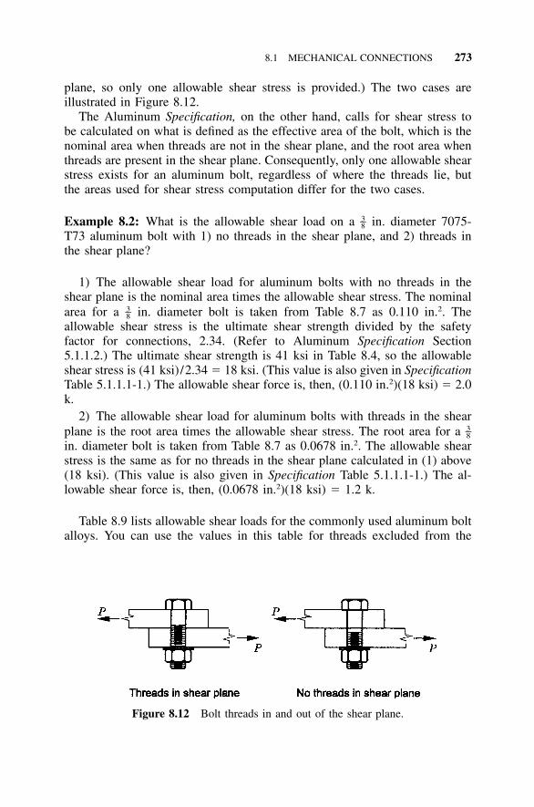
8.1 MECHANICAL CONNECTIONS 273
Figure 8.12 Bolt threads in and out of the shear plane.
plane, so only one allowable shear stress is provided.) The two cases areillustrated in Figure 8.12.
The Aluminum Specification, on the other hand, calls for shear stress tobe calculated on what is defined as the effective area of the bolt, which is thenominal area when threads are not in the shear plane, and the root area whenthreads are present in the shear plane. Consequently, only one allowable shearstress exists for an aluminum bolt, regardless of where the threads lie, butthe areas used for shear stress computation differ for the two cases.
Example 8.2: What is the allowable shear load on a in. diameter 7075-3–8T73 aluminum bolt with 1) no threads in the shear plane, and 2) threads inthe shear plane?
1) The allowable shear load for aluminum bolts with no threads in theshear plane is the nominal area times the allowable shear stress. The nominalarea for a in. diameter bolt is taken from Table 8.7 as 0.110 in.2. The3–8allowable shear stress is the ultimate shear strength divided by the safetyfactor for connections, 2.34. (Refer to Aluminum Specification Section5.1.1.2.) The ultimate shear strength is 41 ksi in Table 8.4, so the allowableshear stress is (41 ksi) /2.34 � 18 ksi. (This value is also given in SpecificationTable 5.1.1.1-1.) The allowable shear force is, then, (0.110 in.2)(18 ksi) � 2.0k.
2) The allowable shear load for aluminum bolts with threads in the shearplane is the root area times the allowable shear stress. The root area for a 3–8in. diameter bolt is taken from Table 8.7 as 0.0678 in.2. The allowable shearstress is the same as for no threads in the shear plane calculated in (1) above(18 ksi). (This value is also given in Specification Table 5.1.1.1-1.) The al-lowable shear force is, then, (0.0678 in.2)(18 ksi) � 1.2 k.
Table 8.9 lists allowable shear loads for the commonly used aluminum boltalloys. You can use the values in this table for threads excluded from the
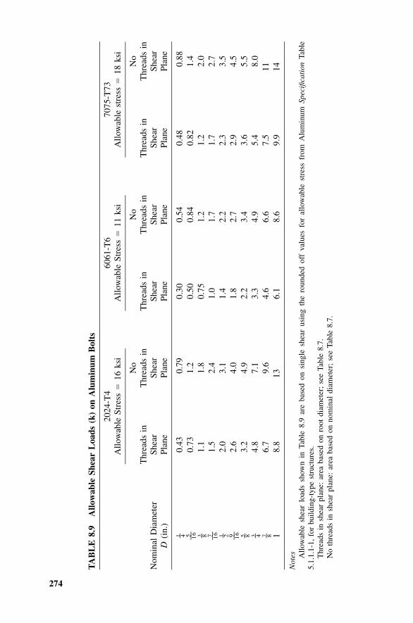
274
TA
BL
E8.
9A
llow
able
Shea
rL
oads
(k)
onA
lum
inum
Bol
ts
Nom
inal
Dia
met
erD
(in.
)
2024
-T4
Allo
wab
leSt
ress
�16
ksi
Thr
eads
inSh
ear
Plan
e
No
Thr
eads
inSh
ear
Plan
e
6061
-T6
Allo
wab
leSt
ress
�11
ksi
Thr
eads
inSh
ear
Plan
e
No
Thr
eads
inSh
ear
Plan
e
7075
-T73
Allo
wab
lest
ress
�18
ksi
Thr
eads
inSh
ear
Plan
e
No
Thr
eads
inSh
ear
Plan
e
1 – 40.
430.
790.
300.
540.
480.
885 –– 16
0.73
1.2
0.50
0.84
0.82
1.4
3 – 81.
11.
80.
751.
21.
22.
07 –– 16
1.5
2.4
1.0
1.7
1.7
2.7
1 – 22.
03.
11.
42.
22.
33.
59 –– 16
2.6
4.0
1.8
2.7
2.9
4.5
5 – 83.
24.
92.
23.
43.
65.
53 – 4
4.8
7.1
3.3
4.9
5.4
8.0
7 – 86.
79.
64.
66.
67.
511
18.
813
6.1
8.6
9.9
14
Not
es Allo
wab
lesh
ear
load
ssh
own
inTa
ble
8.9
are
base
don
sing
lesh
ear
usin
gth
ero
unde
dof
fva
lues
for
allo
wab
lest
ress
from
Alu
min
umSp
ecifi
cati
onTa
ble
5.1.
1.1-
1,fo
rbu
ildin
g-ty
pest
ruct
ures
.T
hrea
dsin
shea
rpl
ane:
area
base
don
root
diam
eter
;se
eTa
ble
8.7.
No
thre
ads
insh
ear
plan
e:ar
eaba
sed
onno
min
aldi
amet
er;
see
Tabl
e8.
7.
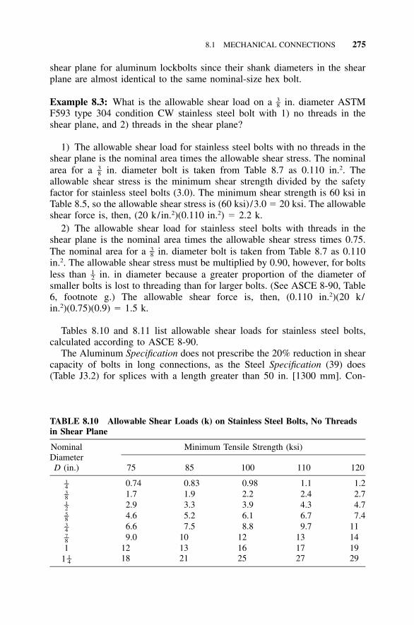
8.1 MECHANICAL CONNECTIONS 275
TABLE 8.10 Allowable Shear Loads (k) on Stainless Steel Bolts, No Threadsin Shear Plane
NominalDiameterD (in.)
Minimum Tensile Strength (ksi)
75 85 100 110 120
1–4 0.74 0.83 0.98 1.1 1.23–8 1.7 1.9 2.2 2.4 2.71–2 2.9 3.3 3.9 4.3 4.75–8 4.6 5.2 6.1 6.7 7.43–4 6.6 7.5 8.8 9.7 117–8 9.0 10 12 13 141 12 13 16 17 19
1 1–4 18 21 25 27 29
shear plane for aluminum lockbolts since their shank diameters in the shearplane are almost identical to the same nominal-size hex bolt.
Example 8.3: What is the allowable shear load on a in. diameter ASTM3–8F593 type 304 condition CW stainless steel bolt with 1) no threads in theshear plane, and 2) threads in the shear plane?
1) The allowable shear load for stainless steel bolts with no threads in theshear plane is the nominal area times the allowable shear stress. The nominalarea for a in. diameter bolt is taken from Table 8.7 as 0.110 in.2. The3–8allowable shear stress is the minimum shear strength divided by the safetyfactor for stainless steel bolts (3.0). The minimum shear strength is 60 ksi inTable 8.5, so the allowable shear stress is (60 ksi) /3.0 � 20 ksi. The allowableshear force is, then, (20 k/in.2)(0.110 in.2) � 2.2 k.
2) The allowable shear load for stainless steel bolts with threads in theshear plane is the nominal area times the allowable shear stress times 0.75.The nominal area for a in. diameter bolt is taken from Table 8.7 as 0.1103–8in.2. The allowable shear stress must be multiplied by 0.90, however, for boltsless than in. in diameter because a greater proportion of the diameter of1–2smaller bolts is lost to threading than for larger bolts. (See ASCE 8-90, Table6, footnote g.) The allowable shear force is, then, (0.110 in.2)(20 k/in.2)(0.75)(0.9) � 1.5 k.
Tables 8.10 and 8.11 list allowable shear loads for stainless steel bolts,calculated according to ASCE 8-90.
The Aluminum Specification does not prescribe the 20% reduction in shearcapacity of bolts in long connections, as the Steel Specification (39) does(Table J3.2) for splices with a length greater than 50 in. [1300 mm]. Con-
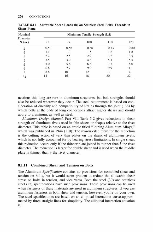
276 CONNECTIONS
TABLE 8.11 Allowable Shear Loads (k) on Stainless Steel Bolts, Threads inShear Plane
NominalDiameterD (in.)
Minimum Tensile Strength (ksi)
75 85 100 110 120
1–4 0.50 0.56 0.66 0.73 0.803–8 1.1 1.3 1.5 1.6 1.81–2 2.2 2.5 2.9 3.2 3.55–8 3.5 3.9 4.6 5.1 5.53–4 5.0 5.6 6.6 7.3 8.07–8 6.8 7.7 9.0 9.9 111 8.8 10 12 13 14
1 1–4 14 16 18 20 22
nections this long are rare in aluminum structures, but bolt strengths shouldalso be reduced wherever they occur. The steel requirement is based on con-sideration of ductility and compatibility of strains through the joint (138) bywhich bolts at the ends of long connections attract higher shears and shouldapply to aluminum, as well as steel.
Aluminum Design Manual, Part VII, Table 5-2 gives reductions in shearstrength of aluminum rivets used in thin sheets or shapes relative to the rivetdiameter. This table is based on an article titled ‘‘Joining Aluminum Alloys,’’which was published in 1944 (110). The reason cited there for the reductionis the cutting action of very thin plates on the shank of aluminum rivets,which is not fully accounted for by bearing stress limitations. In single shear,this reduction occurs only if the thinner plate joined is thinner than the rivet1–3diameter. The reduction is larger for double shear and is used when the middleplate is thinner than the rivet diameter.2–3
8.1.11 Combined Shear and Tension on Bolts
The Aluminum Specification contains no provisions for combined shear andtension on bolts, but it would seem prudent to reduce the allowable shearstress on bolts in tension, and vice versa. Both the steel (39) and stainlesssteel (82) specifications have such provisions. These provisions can be usedwhen fasteners of these materials are used in aluminum structures. If you usealuminum fasteners in both shear and tension, however, you’re on your own.The steel specifications are based on an elliptical interaction curve approxi-mated by three straight lines for simplicity. The elliptical interaction equationis:
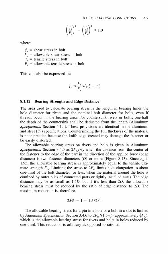
8.1 MECHANICAL CONNECTIONS 277
2 2ƒ ƒs t� � 1.0� � � �F Fs t
where:
ƒs � shear stress in boltFs � allowable shear stress in boltƒt � tensile stress in boltFt � allowable tensile stress in bolt
This can also be expressed as:
Ft 2 2ƒ � �F � ƒt s sFs
8.1.12 Bearing Strength and Edge Distance
The area used to calculate bearing stress is the length in bearing times thehole diameter for rivets and the nominal bolt diameter for bolts, even ifthreads occur in the bearing area. For countersunk rivets or bolts, one-halfthe depth of the countersink shall be deducted from the length (AluminumSpecification Section 5.1.4). These provisions are identical in the aluminumand steel (39) specifications. Countersinking the full thickness of the materialis poor practice because the knife edge created may damage the fastener orbe easily distorted.
The allowable bearing stress on rivets and bolts is given in AluminumSpecification Section 3.4.5 as 2Ftu /nu, when the distance from the center ofthe fastener to the edge of the part in the direction of the applied force (edgedistance) is two fastener diameters (D) or more (Figure 8.13). Since nu is1.95, the allowable bearing stress is approximately equal to the tensile ulti-mate strength Ftu. Limiting the stress to 2Ftu limits hole elongation to aboutone-third of the bolt diameter (or less, when the material around the hole isconfined by outer plies of connected parts or tightly installed nuts). The edgedistance may be as small as 1.5D, but if it’s less than 2D, the allowablebearing stress must be reduced by the ratio of edge distance to 2D. Themaximum reduction is, therefore,
25% � 1 � 1.5/2.0.
The allowable bearing stress for a pin in a hole or a bolt in a slot is limitedby Aluminum Specification Section 3.4.6 to 2Ftu / (1.5nu) (approximately Ftu),
2–3which is the allowable bearing stress for rivets and bolts in holes reduced byone-third. This reduction is arbitrary as opposed to rational.
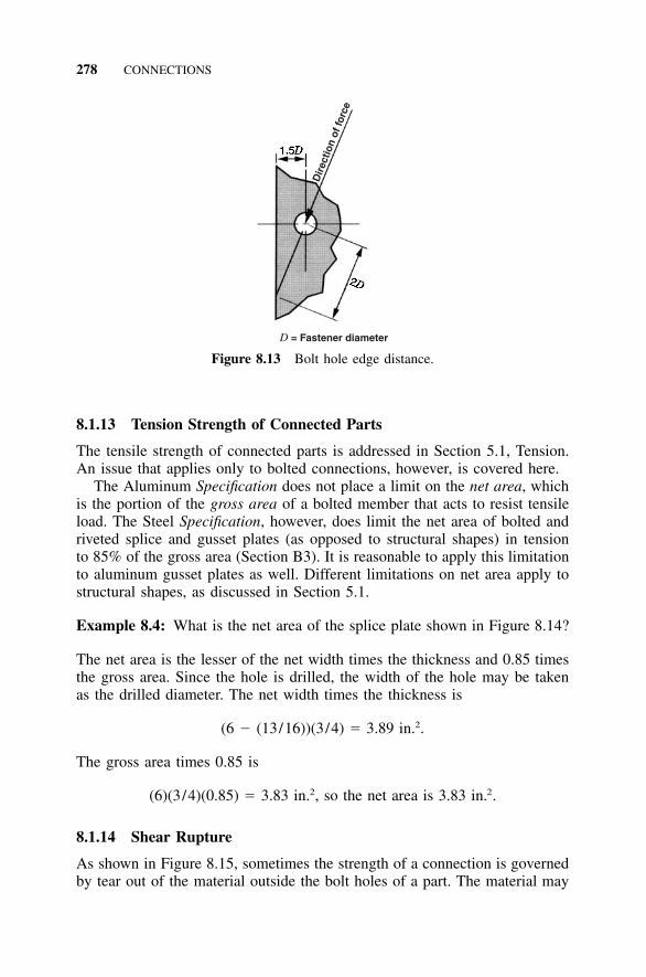
278 CONNECTIONS
Dir
ectio
n of
forc
eD = Fastener diameter
Figure 8.13 Bolt hole edge distance.
8.1.13 Tension Strength of Connected Parts
The tensile strength of connected parts is addressed in Section 5.1, Tension.An issue that applies only to bolted connections, however, is covered here.
The Aluminum Specification does not place a limit on the net area, whichis the portion of the gross area of a bolted member that acts to resist tensileload. The Steel Specification, however, does limit the net area of bolted andriveted splice and gusset plates (as opposed to structural shapes) in tensionto 85% of the gross area (Section B3). It is reasonable to apply this limitationto aluminum gusset plates as well. Different limitations on net area apply tostructural shapes, as discussed in Section 5.1.
Example 8.4: What is the net area of the splice plate shown in Figure 8.14?
The net area is the lesser of the net width times the thickness and 0.85 timesthe gross area. Since the hole is drilled, the width of the hole may be takenas the drilled diameter. The net width times the thickness is
2(6 � (13/16))(3/4) � 3.89 in. .
The gross area times 0.85 is
2 2(6)(3/4)(0.85) � 3.83 in. , so the net area is 3.83 in. .
8.1.14 Shear Rupture
As shown in Figure 8.15, sometimes the strength of a connection is governedby tear out of the material outside the bolt holes of a part. The material may
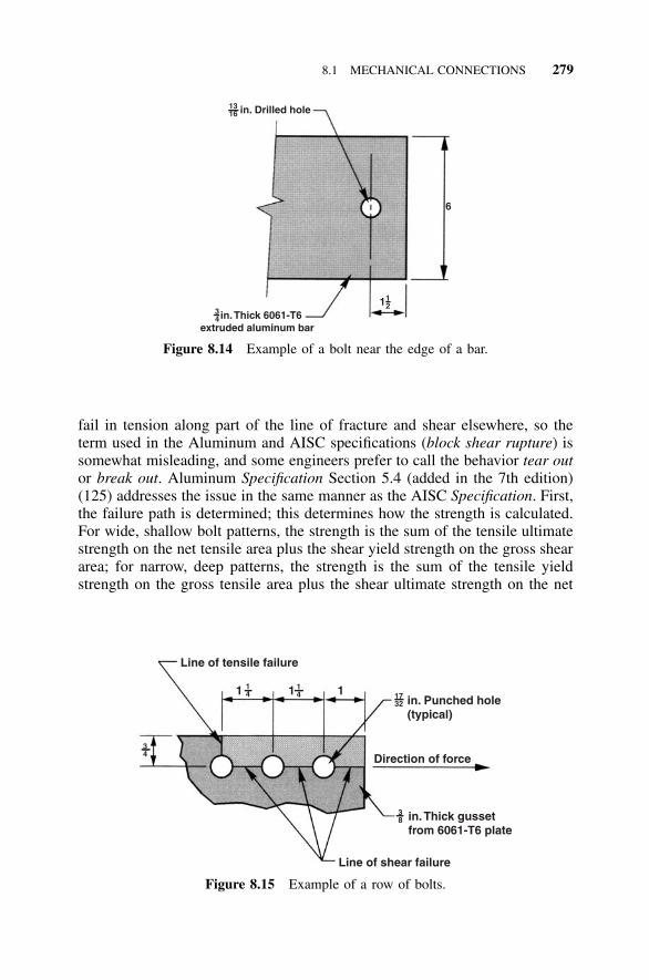
8.1 MECHANICAL CONNECTIONS 279
in. Thick 6061-T6extruded aluminum bar
in. Drilled hole
6
1316
34
121
Figure 8.14 Example of a bolt near the edge of a bar.
Line of tensile failure
in. Punched hole(typical)
Direction of force
in. Thick gussetfrom 6061-T6 plate
Line of shear failure
1 1 1
34
14
14 17
32
38
Figure 8.15 Example of a row of bolts.
fail in tension along part of the line of fracture and shear elsewhere, so theterm used in the Aluminum and AISC specifications (block shear rupture) issomewhat misleading, and some engineers prefer to call the behavior tear outor break out. Aluminum Specification Section 5.4 (added in the 7th edition)(125) addresses the issue in the same manner as the AISC Specification. First,the failure path is determined; this determines how the strength is calculated.For wide, shallow bolt patterns, the strength is the sum of the tensile ultimatestrength on the net tensile area plus the shear yield strength on the gross sheararea; for narrow, deep patterns, the strength is the sum of the tensile yieldstrength on the gross tensile area plus the shear ultimate strength on the net
280 CONNECTIONS
shear area. The Aluminum Specification tear out provisions also apply towelded connections.
Example 8.5: What is the allowable tear out force on the 6061-T6 gussetplate in the direction shown in Figure 8.15?
Since the hole is punched, the effective width of the hole is the nominalhole diameter plus 1 17 1 9–– –– –– ––in. � � � in.32 32 32 16
3 3 2– –gross tensile area � A � ( )( ) � 0.281 in.gt 4 8
3 1 9 3 2– – –– –net tensile area � A � ( � ( ) )( ) � 0.176 in.nt 4 2 16 8
1 1 3 2– – –gross shear area � A � (1 � 1 � 1)( ) � 1.312 in.gv 4 4 8
1 1 9 3 2– – –– –net shear area � A � (1 � 1 � 1 � 2.5( ))( ) � 0.785 in.nv 4 4 16 8
2 2F A � (42 k/in. )(0.176 in. ) � 7.4 k � F Atu nt su nv
2 2� (27 k/in. )(0.785 in. ) � 21.2 k, so
allowable tear out force
� P � (F A � F A ) /nsr su nv ty gt u
2 2 2 2� [((27 k/in. )(0.785 in. ) � (35 k/in. )(0.281 in. )] /1.95
� 15.9 k
For a single bolt connection (Figure 8.11), the Specification break outstrength is always greater than the Specification bearing strength, so you don’tneed to check tear out. This can be demonstrated by calculating bearing andtear out strengths for an edge distance of 1.5D and 2D:
For an edge distance of 1.5D, the bearing strength is:
F � (1.5D /2D)2F Dt � 1.5F Dtbrg tu tu
and the tear out strength is:
F � 2(1.5D)0.6F t � 1.8F Dtbo tu tu
For an edge distance of 2D, the bearing strength is:
F � 2F Dtbrg tu
8.1 MECHANICAL CONNECTIONS 281
and the tear out strength is:
F � 2(2D)0.6F t � 2.4F Dtbo tu tu
For greater edge distances, the tear out strength increases while the bearingstrength remains 2FtuDt.
8.1.15 Minimum Spacing and Edge Distance
For spacing and edge distances, all distances are measured from the centerof the hole in the Aluminum Specification. The Specification allows a mini-mum spacing between bolts of 2 times the bolt diameter and 3 diameters1–2for rivets (see Section 5.1.9), compared to 2 or 3 diameters that the AISC2–3requires, depending on how bearing stresses are limited. While the steel pro-visions are more precise and relate such factors as edge distance and spacingto bearing strength, the Aluminum Specification gives fairly similar results tosteel and are simple to apply. Using the Aluminum Association spacing of2 diameters does not place bolts so close together that adjacent bolts hamper1–2installation. As discussed above with respect to bearing, the minimum edgedistance for aluminum is two fastener diameters unless allowable bearingstresses are reduced. Bolt and rivet edge distances and spacings are given inTable 8.12 for common fastener diameters.
Some specifications refer to distances from the fastener to the edge of themember in a direction perpendicular to the force direction as edge distance,and to distances from the fastener to the edge of the member in the directionof force as end distance (Figure 8.16).
Example 8.6: What is the allowable bearing stress on the rightmost boltshown in Figure 8.15?
The allowable bearing stress for bolts is
2F /n � 2 (42 ksi)/1.95 � 43 ksi.tu u
This value need not be reduced for edge distance since the edge distance is
1.0 in. � 2 ( in.) � 2 (bolt diameter).1–2
8.1.16 Maximum Edge Distance and Spacing
In built-up compression members, the Aluminum Specification dictates max-imum fastener spacing to prevent buckling between fasteners (see Figure8.17). Material between fasteners should be treated as a flat plate supportedalong both edges. As a result, it can be checked for local buckling using the
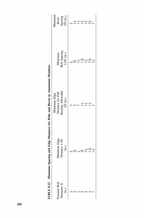
282
TA
BL
E8.
12M
inim
umSp
acin
gan
dE
dge
Dis
tanc
esfo
rB
olts
and
Riv
ets
inA
lum
inum
Mem
bers
Nom
inal
Bol
tD
iam
eter
D(i
n.)
Min
imum
Edg
eD
ista
nce
1.5D
(in.
)
Min
imum
Edg
eD
ista
nce
for
Full
Bea
ring
Allo
wab
le2D
(in.
)
Min
imum
Bol
tSp
acin
g2.
5D(i
n.)
Min
imum
Riv
etSp
acin
g3D
(in.
)
1 – 43 – 8
1 – 25 – 8
3 – 43 – 8
9 –– 163 – 4
15 –– 1 6
11 – 8
1 – 23 – 4
11
1 – 41
1 – 25 – 8
15 –– 1 6
11 – 4
19 –– 16
17 – 8
3 – 41
1 – 81
1 – 21
7 – 82
1 – 47 – 8
15 –– 16
13 – 4
23 –– 16
25 – 8
11
1 – 22
21 – 2
3
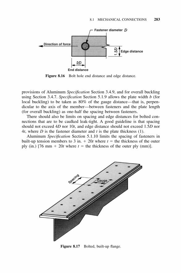
8.1 MECHANICAL CONNECTIONS 283
Fastener diameter
Direction of force
Edge distance
End distance
Figure 8.16 Bolt hole end distance and edge distance.
GaugeSpacing
Figure 8.17 Bolted, built-up flange.
provisions of Aluminum Specification Section 3.4.9, and for overall bucklingusing Section 3.4.7. Specification Section 5.1.9 allows the plate width b (forlocal buckling) to be taken as 80% of the gauge distance—that is, perpen-dicular to the axis of the member—between fasteners and the plate length(for overall buckling) as one-half the spacing between fasteners.
There should also be limits on spacing and edge distances for bolted con-nections that are to be caulked leak-tight. A good guideline is that spacingshould not exceed 4D nor 10t, and edge distance should not exceed 1.5D nor4t, where D is the fastener diameter and t is the plate thickness (1).
Aluminum Specification Section 5.1.10 limits the spacing of fasteners inbuilt-up tension members to 3 in. � 20t where t � the thickness of the outerply (in.) [76 mm � 20t where t � the thickness of the outer ply (mm)].
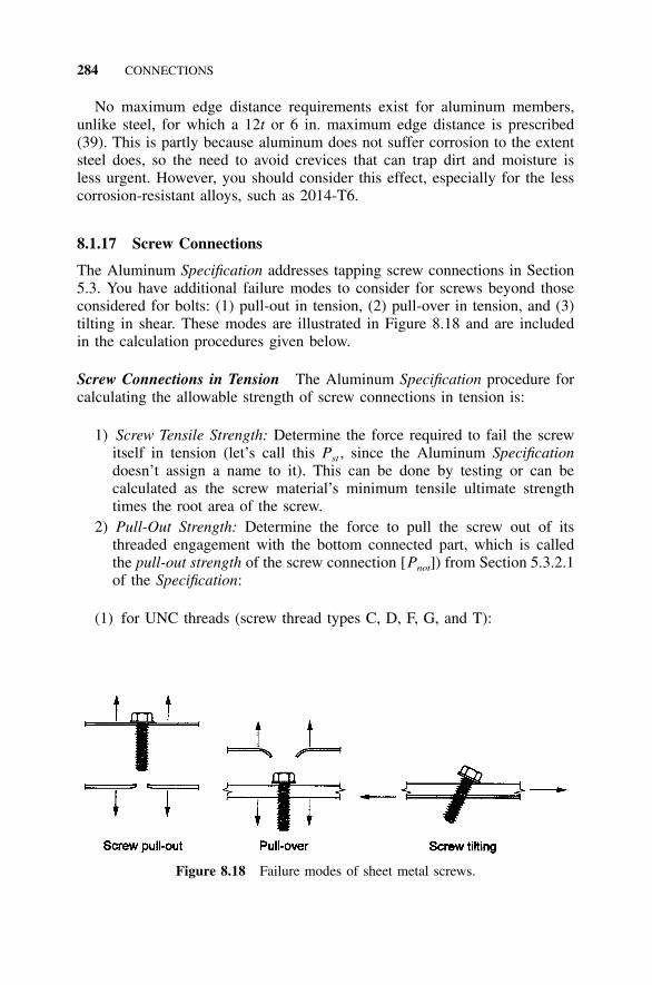
284 CONNECTIONS
Figure 8.18 Failure modes of sheet metal screws.
No maximum edge distance requirements exist for aluminum members,unlike steel, for which a 12t or 6 in. maximum edge distance is prescribed(39). This is partly because aluminum does not suffer corrosion to the extentsteel does, so the need to avoid crevices that can trap dirt and moisture isless urgent. However, you should consider this effect, especially for the lesscorrosion-resistant alloys, such as 2014-T6.
8.1.17 Screw Connections
The Aluminum Specification addresses tapping screw connections in Section5.3. You have additional failure modes to consider for screws beyond thoseconsidered for bolts: (1) pull-out in tension, (2) pull-over in tension, and (3)tilting in shear. These modes are illustrated in Figure 8.18 and are includedin the calculation procedures given below.
Screw Connections in Tension The Aluminum Specification procedure forcalculating the allowable strength of screw connections in tension is:
1) Screw Tensile Strength: Determine the force required to fail the screwitself in tension (let’s call this Pst , since the Aluminum Specificationdoesn’t assign a name to it). This can be done by testing or can becalculated as the screw material’s minimum tensile ultimate strengthtimes the root area of the screw.
2) Pull-Out Strength: Determine the force to pull the screw out of itsthreaded engagement with the bottom connected part, which is calledthe pull-out strength of the screw connection [Pnot]) from Section 5.3.2.1of the Specification:
(1) for UNC threads (screw thread types C, D, F, G, and T):
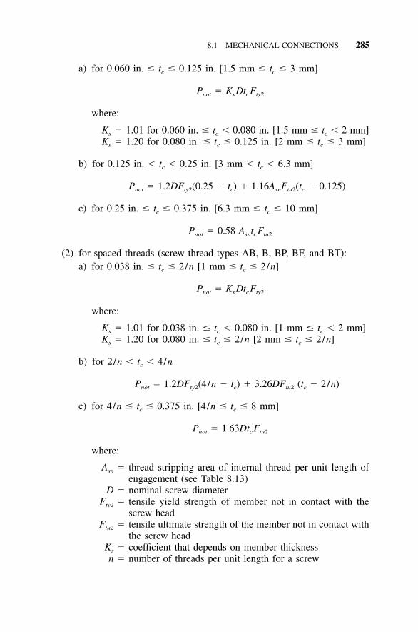
8.1 MECHANICAL CONNECTIONS 285
a) for 0.060 in. � tc � 0.125 in. [1.5 mm � tc � 3 mm]
P � K Dt Fnot s c ty2
where:
Ks � 1.01 for 0.060 in. � tc � 0.080 in. [1.5 mm � tc � 2 mm]Ks � 1.20 for 0.080 in. � tc � 0.125 in. [2 mm � tc � 3 mm]
b) for 0.125 in. � tc � 0.25 in. [3 mm � tc � 6.3 mm]
P � 1.2DF (0.25 � t ) � 1.16A F (t � 0.125)not ty2 c sn tu2 c
c) for 0.25 in. � tc � 0.375 in. [6.3 mm � tc � 10 mm]
P � 0.58 A t Fnot sn c tu2
(2) for spaced threads (screw thread types AB, B, BP, BF, and BT):a) for 0.038 in. � tc � 2/n [1 mm � tc � 2/n]
P � K Dt Fnot s c ty2
where:
Ks � 1.01 for 0.038 in. � tc � 0.080 in. [1 mm � tc � 2 mm]Ks � 1.20 for 0.080 in. � tc � 2/n [2 mm � tc � 2/n]
b) for 2/n � tc � 4/n
P � 1.2DF (4/n � t ) � 3.26DF (t � 2/n)not ty2 c tu2 c
c) for 4/n � tc � 0.375 in. [4/n � tc � 8 mm]
P � 1.63Dt Fnot c tu2
where:
Asn � thread stripping area of internal thread per unit length ofengagement (see Table 8.13)
D � nominal screw diameterFty2 � tensile yield strength of member not in contact with the
screw headFtu2 � tensile ultimate strength of the member not in contact with
the screw headKs � coefficient that depends on member thicknessn � number of threads per unit length for a screw
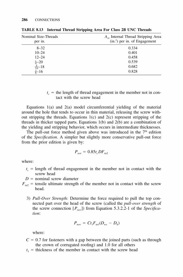
286 CONNECTIONS
TABLE 8.13 Internal Thread Stripping Area For Class 2B UNC Threads
Nominal Size-Threadsper in.
Asn Internal Thread Stripping Area(in.2) per in. of Engagement
8–32 0.33410–24 0.40112–24 0.458
–201–4 0.539–185––16 0.682
–163–8 0.828
tc � the length of thread engagement in the member not in con-tact with the screw head
Equations 1(a) and 2(a) model circumferential yielding of the materialaround the hole that tends to occur in thin material, releasing the screw with-out stripping the threads. Equations 1(c) and 2(c) represent stripping of thethreads in thicker tapped parts. Equations 1(b) and 2(b) are a combination ofthe yielding and stripping behavior, which occurs in intermediate thicknesses.
The pull-out force method given above was introduced in the 7th editionof the Specification. A simpler but slightly more conservative pull-out forcefrom the prior edition is given by:
P � 0.85t DFnot c tu2
where:
tc � length of thread engagement in the member not in contact with thescrew head
D � nominal screw diameterFtu2 � tensile ultimate strength of the member not in contact with the screw
head.
3) Pull-Over Strength: Determine the force required to pull the top con-nected part over the head of the screw (called the pull-over strength ofthe screw connection [Pnov]) from Equation 5.3.2.2-1 of the Specifica-tion:
P � Ct F (D � D )nov 1 tu1 ws h
where:
C � 0.7 for fasteners with a gap between the joined parts (such as throughthe crown of corrugated roofing) and 1.0 for all others
t1 � thickness of the member in contact with the screw head
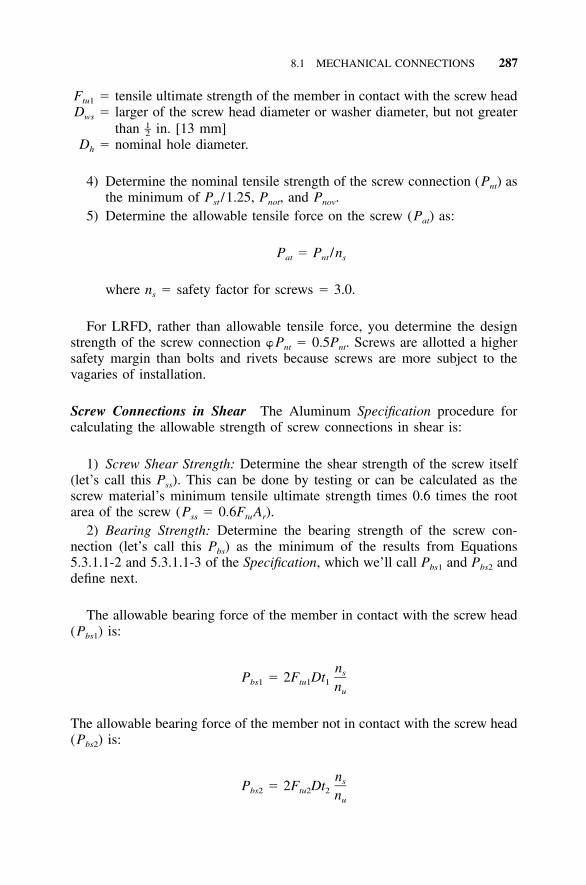
8.1 MECHANICAL CONNECTIONS 287
Ftu1 � tensile ultimate strength of the member in contact with the screw headDws � larger of the screw head diameter or washer diameter, but not greater
than in. [13 mm]1–2Dh � nominal hole diameter.
4) Determine the nominal tensile strength of the screw connection (Pnt) asthe minimum of Pst /1.25, Pnot, and Pnov.
5) Determine the allowable tensile force on the screw (Pat) as:
P � P /nat nt s
where ns � safety factor for screws � 3.0.
For LRFD, rather than allowable tensile force, you determine the designstrength of the screw connection Pnt � 0.5Pnt. Screws are allotted a highersafety margin than bolts and rivets because screws are more subject to thevagaries of installation.
Screw Connections in Shear The Aluminum Specification procedure forcalculating the allowable strength of screw connections in shear is:
1) Screw Shear Strength: Determine the shear strength of the screw itself(let’s call this Pss). This can be done by testing or can be calculated as thescrew material’s minimum tensile ultimate strength times 0.6 times the rootarea of the screw (Pss � 0.6FtuAr).
2) Bearing Strength: Determine the bearing strength of the screw con-nection (let’s call this Pbs) as the minimum of the results from Equations5.3.1.1-2 and 5.3.1.1-3 of the Specification, which we’ll call Pbs1 and Pbs2 anddefine next.
The allowable bearing force of the member in contact with the screw head(Pbs1) is:
nsP � 2F Dtbs1 tu1 1 nu
The allowable bearing force of the member not in contact with the screw head(Pbs2) is:
nsP � 2F Dtbs2 tu2 2 nu
288 CONNECTIONS
where:
ns � safety factor for screw connections � 3.0nu � safety factor for fracture � 1.95D � nominal screw diameter
Ftu1 � tension ultimate strength of the member in contact with the screwhead
Ftu2 � tension ultimate strength of the member not in contact with the screwhead
t1 � thickness of the member in contact with the screw headt2 � thickness of the member not in contact with the screw head
3) Screw Tilting: If the thicker of the two members joined is in contactwith the screw head—in other words, t1 � t2, meaning the top material isthicker than the bottom material, an unlikely situation if you’re screwing sheetto a structural member—determine the tilting strength of the screw connection(let’s call this Pts) from Equation 5.3.1.1-4 of the Specification:
3 1 / 2P � 4.2(t D) Fts 2 tu2
where Ftu2 � tensile ultimate strength of the member not in contact with thescrew head.
4) Determine the nominal shear strength of the screw connection (Pns) asthe minimum of Pss /1.25, Pbs, and Pts.
5) Determine the allowable shear force on the screw (Pas) as:
P � P /nas ns s
where ns � safety factor for screws � 3.0.For LRFD, rather than allowable shear force, determine the design strength
of the screw connection, which is
P � 0.5P .ns ns
8.1.18 Minimum Requirements for Connections
The Aluminum Specification, unlike the Steel Specification, does not requireminimum connection strengths. (See the AISC Section J1.6 (38), which re-quires that connections carrying calculated stresses be designed to supportnot less than 6 k.) Because the Aluminum Specification covers a wide varietyof structures, some of which might be designed for only light loads, this isnot altogether surprising. However, when aluminum structures are designedfor building-type structures, it’s appropriate to consider certain size connec-tions as a minimum, even if smaller fasteners could be demonstrated to workon paper. As a practical matter, the smaller and fewer the fasteners, the more
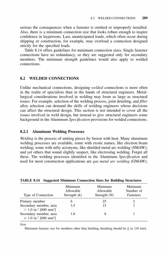
8.2 WELDED CONNECTIONS 289
TABLE 8.14 Suggested Minimum Connection Sizes for Building Structures
Type of Connection
MinimumAllowable
Strength (k)
MinimumAllowable
Strength (N)
MinimumNumber ofFasteners
Primary member 6 25 2Secondary member, area
� 1.0 in.2 [600 mm2]3.5 15 1
Secondary member, area� 1.0 in.2 [600 mm2]
1.8 8 1
NoteMinimum fastener size for members other than building sheathing should be in. [10 mm].3–8
serious the consequences when a fastener is omitted or improperly installed.Also, there is a minimum connection size that looks robust enough to inspireconfidence in laypersons. Last, unanticipated loads, which often occur duringshipping or construction, for example, may overload a connection designedstrictly for the specified loads.
Table 8.14 offers guidelines for minimum connection sizes. Single fastenerconnections have no redundancy, so they are suggested only for secondarymembers. The minimum strength guidelines would also apply to weldedconnections.
8.2 WELDED CONNECTIONS
Unlike mechanical connections, designing welded connections is more oftenin the realm of specialists than in the hands of structural engineers. Metal-lurgical considerations involved in welding may loom as large as structuralissues. For example, selection of the welding process, joint detailing, and filleralloy selection can demand the skills of welding engineers whose decisionscan affect the structural design. This section is not intended to cover all theissues involved in weld design, but instead to give structural engineers somebackground in the Aluminum Specification provisions for welded connections.
8.2.1 Aluminum Welding Processes
Welding is the process of uniting pieces by fusion with heat. Many aluminumwelding processes are available, some with exotic names, like electron beamwelding; some with nifty acronyms, like shielded metal arc welding (SMAW);and yet others that sound slightly suspect, like electroslag welding. Forget allthese. The welding processes identified in the Aluminum Specification andused for most construction applications are gas metal arc welding (GMAW),
290 CONNECTIONS
commonly called MIG (for metal inert gas); and gas tungsten arc welding(GTAW), referred to as TIG (tungsten inert gas). These are the processes forwhich minimum welded mechanical properties are given in the SpecificationTable 3.3-2. For other processes, you’re on your own—and that can be alonely place.
As a structural engineer, you don’t need to know how MIG and TIG weldsare made. You can leave that to the fabricator’s welding engineer, but it mightbe helpful to have a rough idea of what these weld processes are. MIG weld-ing uses an electric arc within a shield of inert gas between the base metaland an electrode filler wire. The electrode wire is pulled from a spool by awire-feed mechanism and delivered to the arc through a gun. In TIG welding,the base metal and, if used, filler metal are melted by an arc between thebase metal and a nonconsumable tungsten electrode in a holder. Tungsten isused because it has the highest melting point of any metal (6,170�F [3,410�C])and reasonably good conductivity: about one-third that of copper. Inert gasthat flows from a nozzle on the holder shields the weld metal and the elec-trode. In both MIG and TIG welding, the inert gas (usually argon, sometimeshelium, or some of each) protects the molten metal from oxidation, allowingcoalescence of the base and filler metals.
TIG welding was developed before MIG and was originally used for allmetal thicknesses. TIG welding, however, is slower and doesn’t penetrate aswell as MIG welding. With the development of MIG welding, TIG has beengenerally limited to welding thin material (up to about in. [6 mm] thick).1–4In MIG welding, the welding machine controls the electrode wire speed, andonce it is adjusted to a particular welding procedure, doesn’t require read-justment. As a result, even manual MIG welding is considered to be semi-automatic. MIG welding is suitable for all aluminum material thicknesses andcosts about $5 /ft [$16/m] once all labor, consumable, and material costs areincluded.
Before 1983, the ASME Boiler and Pressure Vessel Code, Section IX,Welding and Brazing Qualifications was the only widely available standardfor aluminum welding. Many aluminum structures other than pressure vesselswere welded in accordance with the provisions of the Boiler and PressureVessel Code because no other standards existed. In 1983, the American Weld-ing Society’s (AWS) D1.2 Structural Welding Code—Aluminum (91) was in-troduced as a standard for general-purpose structural MIG and TIG welding(in other words, everything except aerospace or pressure vessel applications).In addition to rules for qualifying aluminum welders and weld procedures,D1.2 includes design, fabrication, and inspection requirements. The require-ments in D1.2 and the Boiler and Pressure Vessel Code are similar, but D1.2’sformat roughly parallels the AWS structural steel welding code (D1.1) for theconvenience of users since most of them are familiar with steel welding.Unlike D1.1, though, D1.2 does not include design stresses for aluminumwelds; for that, it refers to the Aluminum Specification.
8.2 WELDED CONNECTIONS 291
8.2.2 Selecting a Filler Alloy
The material specification for MIG and TIG filler alloys is AWS A5.10, Spec-ification for Bare Aluminum and Aluminum-Alloy Welding Electrodes andRods (88). The term bare differentiates these fillers from shielded metal arc-welding fillers that come with a crusty flux cover and were used before inert-gas shielding methods were developed in the 1940s.
The structural design of welded connections is a function of the filler wireused in the weld. Table 7.2-1 of the Aluminum Specification dictates the filleralloy based on the parent metal alloy(s). In many cases, several filler alloysmay be used. You have many factors to consider in addition to strength,including ductility, color match after anodizing, corrosion resistance, hot-cracking tendency, MIG wire feedability, and elevated temperature perform-ance. In spite of this, the vast majority of applications use 4043 or 5356 filler,which costs $2.50 to $3.25/lb [$5.50 to $7.00/kg]. (4043 is slightly lessexpensive than 5356, but not enough to override other factors in decidingwhich to use.) Other fillers can cost as much as $10 to $12/lb [$22 to $26/kg] and are not as available, so you need a good reason before using them.
Filler alloys 5356, 5183, and 5556 were developed to weld the 5xxx seriesalloys, but they have also become useful for welding 6xxx and 7xxx alloys.Alloy 5356 is the most commonly used filler due to its good strength, com-patibility with many base metals, and good MIG electrode wire feedability.Alloy 5356 also is used to weld 6xxx series alloys because it provides a bettercolor match with the base metal than 4043 when anodized. (4043 tends toturn black when anodized, a look the architect might not have had in mind.)Alloy 5183 has slightly higher strength than 5356, and 5556 higher still. Themost notable example of where the higher strength of 5556 is needed is forwelding 5083 or 5456. Because 5356, 5183, and 5556 contain more than 3%magnesium and are not heat-treatable, however, they are not suitable for el-evated temperature service or post weld heat treating. Alloy 5554 was devel-oped to weld alloy 5454; both contain less than 3% magnesium so as to besuitable for service more than 150�F [66�C].
Alloy 5654 was developed as a high-purity, corrosion-resistant alloy forwelding 5652, 5154, and 5254 components used for hydrogen peroxideservice. Its magnesium content exceeds 3% so it is not used at elevatedtemperatures.
Alloy 4043 was developed for welding the heat-treatable alloys, especiallythose of the 6xxx series. Its has a lower melting point than the 5xxx fillers,so it flows better and is less sensitive to cracking. Alloy 4643 is for welding6xxx base-metal parts more than 0.375 in. [10 mm] to 0.5 in. [13 mm] thickthat will be heat-treated after welding. Although filler alloys 4047 and 4145are listed for some parent metal combinations in Specification Table 7.2-1,they are primarily used for brazing. Brazing is the process of joining metalsby fusion using filler metals with a melting point above 840�F [450�C], butlower than the melting point of the base metals being joined. Brazing is not
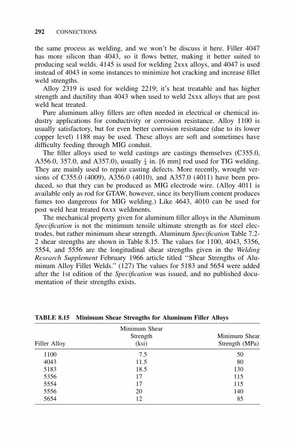
292 CONNECTIONS
TABLE 8.15 Minimum Shear Strengths for Aluminum Filler Alloys
Filler Alloy
Minimum ShearStrength
(ksi)Minimum ShearStrength (MPa)
1100 7.5 504043 11.5 805183 18.5 1305356 17 1155554 17 1155556 20 1405654 12 85
the same process as welding, and we won’t be discuss it here. Filler 4047has more silicon than 4043, so it flows better, making it better suited toproducing seal welds. 4145 is used for welding 2xxx alloys, and 4047 is usedinstead of 4043 in some instances to minimize hot cracking and increase filletweld strengths.
Alloy 2319 is used for welding 2219; it’s heat treatable and has higherstrength and ductility than 4043 when used to weld 2xxx alloys that are postweld heat treated.
Pure aluminum alloy fillers are often needed in electrical or chemical in-dustry applications for conductivity or corrosion resistance. Alloy 1100 isusually satisfactory, but for even better corrosion resistance (due to its lowercopper level) 1188 may be used. These alloys are soft and sometimes havedifficulty feeding through MIG conduit.
The filler alloys used to weld castings are castings themselves (C355.0,A356.0, 357.0, and A357.0), usually in. [6 mm] rod used for TIG welding.1–4They are mainly used to repair casting defects. More recently, wrought ver-sions of C355.0 (4009), A356.0 (4010), and A357.0 (4011) have been pro-duced, so that they can be produced as MIG electrode wire. (Alloy 4011 isavailable only as rod for GTAW, however, since its beryllium content producesfumes too dangerous for MIG welding.) Like 4643, 4010 can be used forpost weld heat treated 6xxx weldments.
The mechanical property given for aluminum filler alloys in the AluminumSpecification is not the minimum tensile ultimate strength as for steel elec-trodes, but rather minimum shear strength. Aluminum Specification Table 7.2-2 shear strengths are shown in Table 8.15. The values for 1100, 4043, 5356,5554, and 5556 are the longitudinal shear strengths given in the WeldingResearch Supplement February 1966 article titled ‘‘Shear Strengths of Alu-minum Alloy Fillet Welds.’’ (127) The values for 5183 and 5654 were addedafter the 1st edition of the Specification was issued, and no published docu-mentation of their strengths exists.
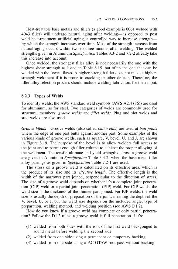
8.2 WELDED CONNECTIONS 293
Heat-treatable base metals and fillers (a good example is 6061 welded with4043 filler) will undergo natural aging after welding—as opposed to postweld heat-treatment artificial aging, a controlled way to increase strength—by which the strength increases over time. Most of the strength increase fromnatural aging occurs within two to three months after welding. The weldedstrengths given in Aluminum Specification Tables 3.3-2 and 7.2-2 already takethis increase into account.
Once welded, the strongest filler alloy is not necessarily the one with thehighest shear strength as listed in Table 8.15, but often the one that can bewelded with the fewest flaws. A higher-strength filler does not make a higher-strength weldment if it is prone to cracking or other defects. Therefore, thefiller alloy selection process should include welding fabricators for their input.
8.2.3 Types of Welds
To identify welds, the AWS standard weld symbols (AWS A2.4 (86)) are usedfor aluminum, as for steel. Two categories of welds are commonly used forstructural members: groove welds and fillet welds. Plug and slot welds andstud welds are also used.
Groove Welds Groove welds (also called butt welds) are used at butt jointswhere the edge of one part butts against another part. Some examples of thevarious kinds of groove welds, such as square, V, bevel, U, and J, are shownin Figure 8.19. The purpose of the bevel is to allow welders full access tothe joint and to permit enough filler volume to achieve the proper alloying ofthe weldment. The tensile ultimate and yield strengths across a groove weldare given in Aluminum Specification Table 3.3-2, when the base metal-filleralloy pairings as given in Specification Table 7.2-1 are used.
The stress on a groove weld is calculated on its effective area, which isthe product of its size and its effective length. The effective length is thewidth of the narrower part joined, perpendicular to the direction of stress.The size of a groove weld depends on whether it’s a complete joint penetra-tion (CJP) weld or a partial joint penetration (PJP) weld. For CJP welds, theweld size is the thickness of the thinner part joined. For PJP welds, the weldsize is usually the depth of preparation of the joint, meaning the depth of theV, bevel, U, or J, but the weld size depends on the included angle, type ofpreparation, welding method, and welding position (see AWS D1.2).
How do you know if a groove weld has complete or only partial penetra-tion? Follow the D1.2 rules: a groove weld is full penetration if it’s:
(1) welded from both sides with the root of the first weld backgouged tosound metal before welding the second side
(2) welded from one side using a permanent or temporary backing(3) welded from one side using a AC-GTAW root pass without backing
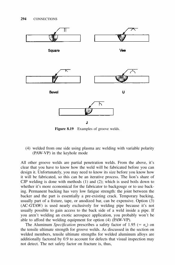
294 CONNECTIONS
Figure 8.19 Examples of groove welds.
(4) welded from one side using plasma arc welding with variable polarity(PAW-VP) in the keyhole mode
All other groove welds are partial penetration welds. From the above, it’sclear that you have to know how the weld will be fabricated before you candesign it. Unfortunately, you may need to know its size before you know howit will be fabricated, so this can be an iterative process. The lion’s share ofCJP welding is done with methods (1) and (2); which is used boils down towhether it’s more economical for the fabricator to backgouge or to use back-ing. Permanent backing has very low fatigue strength: the joint between thebacker and the part is essentially a pre-existing crack. Temporary backing,usually part of a fixture, tape, or anodized bar, can be expensive. Option (3)(AC-GTAW) is used nearly exclusively for welding pipe because it’s notusually possible to gain access to the back side of a weld inside a pipe. Ifyou aren’t welding an exotic aerospace application, you probably won’t beable to afford the welding equipment for option (4) (PAW-VP).
The Aluminum Specification prescribes a safety factor of 1.95 (� nu) onthe tensile ultimate strength for groove welds. As discussed in the section onwelded members, tensile ultimate strengths for welded aluminum alloys areadditionally factored by 0.9 to account for defects that visual inspection maynot detect. The net safety factor on fracture is, thus,
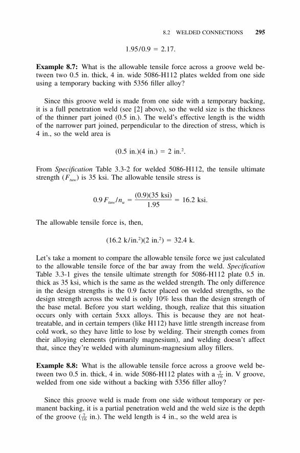
8.2 WELDED CONNECTIONS 295
1.95/0.9 � 2.17.
Example 8.7: What is the allowable tensile force across a groove weld be-tween two 0.5 in. thick, 4 in. wide 5086-H112 plates welded from one sideusing a temporary backing with 5356 filler alloy?
Since this groove weld is made from one side with a temporary backing,it is a full penetration weld (see [2] above), so the weld size is the thicknessof the thinner part joined (0.5 in.). The weld’s effective length is the widthof the narrower part joined, perpendicular to the direction of stress, which is4 in., so the weld area is
2(0.5 in.)(4 in.) � 2 in. .
From Specification Table 3.3-2 for welded 5086-H112, the tensile ultimatestrength (Ftuw) is 35 ksi. The allowable tensile stress is
(0.9)(35 ksi)0.9 F /n � � 16.2 ksi.tuw u 1.95
The allowable tensile force is, then,
2 2(16.2 k/in. )(2 in. ) � 32.4 k.
Let’s take a moment to compare the allowable tensile force we just calculatedto the allowable tensile force of the bar away from the weld. SpecificationTable 3.3-1 gives the tensile ultimate strength for 5086-H112 plate 0.5 in.thick as 35 ksi, which is the same as the welded strength. The only differencein the design strengths is the 0.9 factor placed on welded strengths, so thedesign strength across the weld is only 10% less than the design strength ofthe base metal. Before you start welding, though, realize that this situationoccurs only with certain 5xxx alloys. This is because they are not heat-treatable, and in certain tempers (like H112) have little strength increase fromcold work, so they have little to lose by welding. Their strength comes fromtheir alloying elements (primarily magnesium), and welding doesn’t affectthat, since they’re welded with aluminum-magnesium alloy fillers.
Example 8.8: What is the allowable tensile force across a groove weld be-tween two 0.5 in. thick, 4 in. wide 5086-H112 plates with a in. V groove,7––16
welded from one side without a backing with 5356 filler alloy?
Since this groove weld is made from one side without temporary or per-manent backing, it is a partial penetration weld and the weld size is the depthof the groove ( in.). The weld length is 4 in., so the weld area is7––16
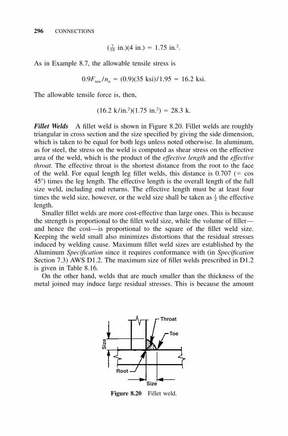
296 CONNECTIONS
Throat
Toe
Siz
e
Root
Size
Figure 8.20 Fillet weld.
7 2––( in.)(4 in.) � 1.75 in. .16
As in Example 8.7, the allowable tensile stress is
0.9F /n � (0.9)(35 ksi) /1.95 � 16.2 ksi.tuw u
The allowable tensile force is, then,
2 2(16.2 k/in. )(1.75 in. ) � 28.3 k.
Fillet Welds A fillet weld is shown in Figure 8.20. Fillet welds are roughlytriangular in cross section and the size specified by giving the side dimension,which is taken to be equal for both legs unless noted otherwise. In aluminum,as for steel, the stress on the weld is computed as shear stress on the effectivearea of the weld, which is the product of the effective length and the effectivethroat. The effective throat is the shortest distance from the root to the faceof the weld. For equal length leg fillet welds, this distance is 0.707 (� cos45�) times the leg length. The effective length is the overall length of the fullsize weld, including end returns. The effective length must be at least fourtimes the weld size, however, or the weld size shall be taken as the effective1–4length.
Smaller fillet welds are more cost-effective than large ones. This is becausethe strength is proportional to the fillet weld size, while the volume of filler—and hence the cost—is proportional to the square of the fillet weld size.Keeping the weld small also minimizes distortions that the residual stressesinduced by welding cause. Maximum fillet weld sizes are established by theAluminum Specification since it requires conformance with (in SpecificationSection 7.3) AWS D1.2. The maximum size of fillet welds prescribed in D1.2is given in Table 8.16.
On the other hand, welds that are much smaller than the thickness of themetal joined may induce large residual stresses. This is because the amount
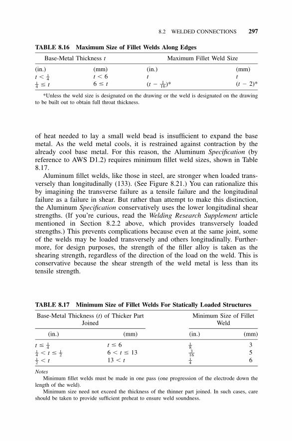
8.2 WELDED CONNECTIONS 297
TABLE 8.16 Maximum Size of Fillet Welds Along Edges
Base-Metal Thickness t Maximum Fillet Weld Size
(in.)t � 1–4
� t1–4
(mm)t � 66 � t
(in.)t(t � )*1––16
(mm)t(t � 2)*
*Unless the weld size is designated on the drawing or the weld is designated on the drawingto be built out to obtain full throat thickness.
TABLE 8.17 Minimum Size of Fillet Welds For Statically Loaded Structures
Base-Metal Thickness (t) of Thicker PartJoined
(in.) (mm)
Minimum Size of FilletWeld
(in.) (mm)
t � 1–4 t � 6 1–8 3� t �1 1– –4 2 6 � t � 13 3––16 5� t1–2 13 � t 1–4 6
NotesMinimum fillet welds must be made in one pass (one progression of the electrode down the
length of the weld).Minimum size need not exceed the thickness of the thinner part joined. In such cases, care
should be taken to provide sufficient preheat to ensure weld soundness.
of heat needed to lay a small weld bead is insufficient to expand the basemetal. As the weld metal cools, it is restrained against contraction by thealready cool base metal. For this reason, the Aluminum Specification (byreference to AWS D1.2) requires minimum fillet weld sizes, shown in Table8.17.
Aluminum fillet welds, like those in steel, are stronger when loaded trans-versely than longitudinally (133). (See Figure 8.21.) You can rationalize thisby imagining the transverse failure as a tensile failure and the longitudinalfailure as a failure in shear. But rather than attempt to make this distinction,the Aluminum Specification conservatively uses the lower longitudinal shearstrengths. (If you’re curious, read the Welding Research Supplement articlementioned in Section 8.2.2 above, which provides transversely loadedstrengths.) This prevents complications because even at the same joint, someof the welds may be loaded transversely and others longitudinally. Further-more, for design purposes, the strength of the filler alloy is taken as theshearing strength, regardless of the direction of the load on the weld. This isconservative because the shear strength of the weld metal is less than itstensile strength.
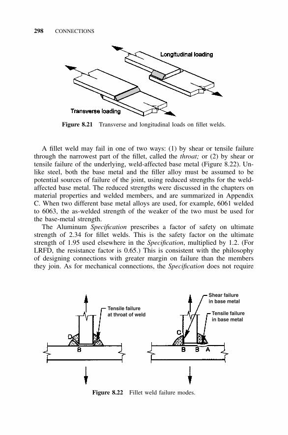
298 CONNECTIONS
Figure 8.21 Transverse and longitudinal loads on fillet welds.
Tensile failureat throat of weld
Shear failurein base metal
Tensile failurein base metal
Figure 8.22 Fillet weld failure modes.
A fillet weld may fail in one of two ways: (1) by shear or tensile failurethrough the narrowest part of the fillet, called the throat; or (2) by shear ortensile failure of the underlying, weld-affected base metal (Figure 8.22). Un-like steel, both the base metal and the filler alloy must be assumed to bepotential sources of failure of the joint, using reduced strengths for the weld-affected base metal. The reduced strengths were discussed in the chapters onmaterial properties and welded members, and are summarized in AppendixC. When two different base metal alloys are used, for example, 6061 weldedto 6063, the as-welded strength of the weaker of the two must be used forthe base-metal strength.
The Aluminum Specification prescribes a factor of safety on ultimatestrength of 2.34 for fillet welds. This is the safety factor on the ultimatestrength of 1.95 used elsewhere in the Specification, multiplied by 1.2. (ForLRFD, the resistance factor is 0.65.) This is consistent with the philosophyof designing connections with greater margin on failure than the membersthey join. As for mechanical connections, the Specification does not require
8.2 WELDED CONNECTIONS 299
a check on yielding at the welded connection since it does not typicallyconstitute a limit state. The small amount of elongation that would take placedue to yielding at the weld is insignificant compared to the length of thewelded member, except for very short members.
Example 8.9: What is the allowable stress on the fillet weld shown in Figure8.22 and made with 4043 filler alloy on 6061-T6 base metal?
First, let’s consider the shear strength of the filler alloy. The failure planeis along line BD. From Table 8.15, the minimum shear strength of the 4043filler is 11.5 ksi. The allowable shear stress in the filler alloy is, then,
(11.5 ksi) /2.34 � 4.9 ksi.
Next, consider the base metal. One mode of failure is that the base metal canfail in tension along line AB, which is 1.41 times the length of line BD. Theminimum welded tensile ultimate strength of the 6061-T6 base metal is foundin Aluminum Specification Table 3.3-2 as
F � 24 ksi.tuw
The allowable stress on the base metal, adjusting for the longer failure linecompared to the throat, is
1.41(F )(0.9)/1.2n k � 1.41(24 ksi)(0.9)/(2.34)(1.0) � 13 ksi.tuw u t
(Note that for all welded alloys, kt is 1.0 per Specification Table 3.4-2.)The base metal can also fail in shear along line BC, which also is 1.41
times longer than line BD. The minimum welded shear ultimate strength ofthe 6061-T6 base metal is found in Aluminum Specification Table 3.3-2 as
F � 15 ksi.suw
The allowable stress is
1.41(F ) /1.2n � 1.41(15 ksi)/2.34 � 9.0 ksi.suw u
For equal leg fillets, shear failure in the base metal (failure on line BC) willalways govern over tension failure in the base metal (line AB) since the shearstrength is less than the tensile strength.
The least of 4.9 ksi, 13 ksi, and 9.0 ksi is 4.9 ksi, which is rounded to 5ksi, as used for the allowable shear stress for 4043 filler and 6061 base metalin Aluminum Specification Table 7.2-2, Allowable Shear Stresses in FilletWelds for Building Type Structures. For most filler-base metal combinations,the filler alloy shear strength is the weak link and, thus, governs the strengthof the fillet weld.
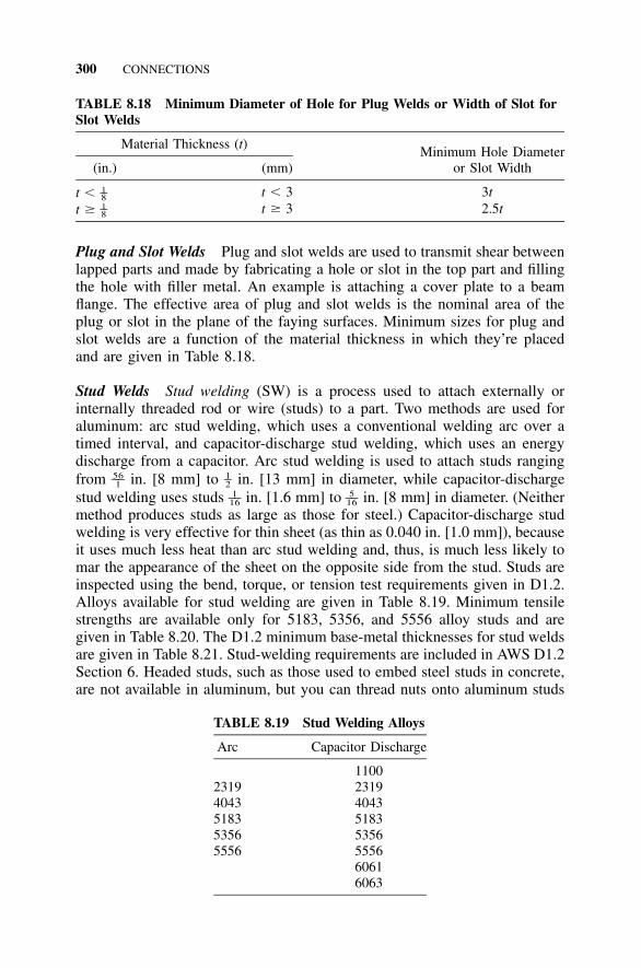
300 CONNECTIONS
TABLE 8.18 Minimum Diameter of Hole for Plug Welds or Width of Slot forSlot Welds
Material Thickness (t)
(in.) (mm)Minimum Hole Diameter
or Slot Width
t � 1–8 t � 3 3tt � 1–8 t � 3 2.5t
Plug and Slot Welds Plug and slot welds are used to transmit shear betweenlapped parts and made by fabricating a hole or slot in the top part and fillingthe hole with filler metal. An example is attaching a cover plate to a beamflange. The effective area of plug and slot welds is the nominal area of theplug or slot in the plane of the faying surfaces. Minimum sizes for plug andslot welds are a function of the material thickness in which they’re placedand are given in Table 8.18.
Stud Welds Stud welding (SW) is a process used to attach externally orinternally threaded rod or wire (studs) to a part. Two methods are used foraluminum: arc stud welding, which uses a conventional welding arc over atimed interval, and capacitor-discharge stud welding, which uses an energydischarge from a capacitor. Arc stud welding is used to attach studs rangingfrom in. [8 mm] to in. [13 mm] in diameter, while capacitor-discharge56 1–– –1 2
stud welding uses studs in. [1.6 mm] to in. [8 mm] in diameter. (Neither1 5–– ––16 16
method produces studs as large as those for steel.) Capacitor-discharge studwelding is very effective for thin sheet (as thin as 0.040 in. [1.0 mm]), becauseit uses much less heat than arc stud welding and, thus, is much less likely tomar the appearance of the sheet on the opposite side from the stud. Studs areinspected using the bend, torque, or tension test requirements given in D1.2.Alloys available for stud welding are given in Table 8.19. Minimum tensilestrengths are available only for 5183, 5356, and 5556 alloy studs and aregiven in Table 8.20. The D1.2 minimum base-metal thicknesses for stud weldsare given in Table 8.21. Stud-welding requirements are included in AWS D1.2Section 6. Headed studs, such as those used to embed steel studs in concrete,are not available in aluminum, but you can thread nuts onto aluminum studs
TABLE 8.19 Stud Welding Alloys
Arc Capacitor Discharge
11002319 23194043 40435183 51835356 53565556 5556
60616063
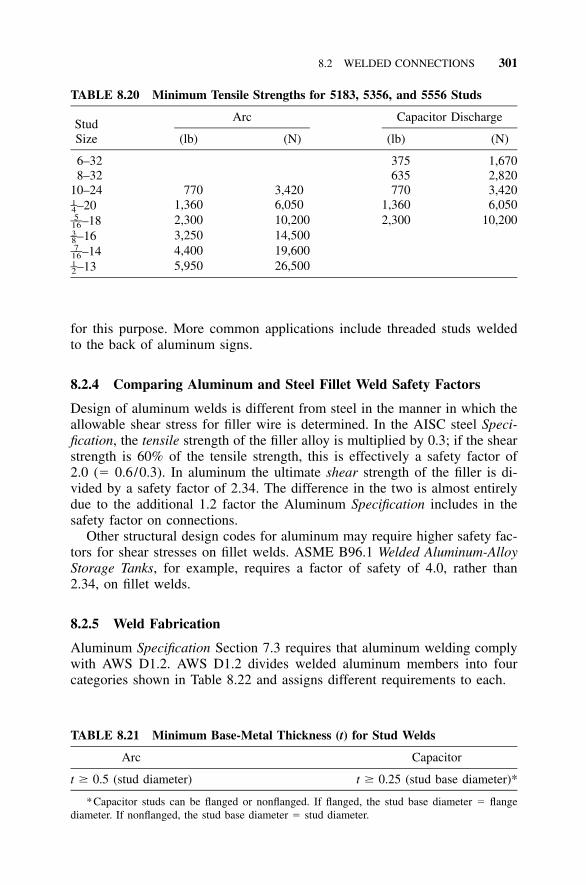
8.2 WELDED CONNECTIONS 301
TABLE 8.20 Minimum Tensile Strengths for 5183, 5356, and 5556 Studs
StudSize
Arc
(lb) (N)
Capacitor Discharge
(lb) (N)
6–32 375 1,6708–32 635 2,820
10–24 770 3,420 770 3,420–201–4 1,360 6,050 1,360 6,050–185––16 2,300 10,200 2,300 10,200
–163–8 3,250 14,500–147––16 4,400 19,600
–131–2 5,950 26,500
TABLE 8.21 Minimum Base-Metal Thickness (t) for Stud Welds
Arc Capacitor
t � 0.5 (stud diameter) t � 0.25 (stud base diameter)*
*Capacitor studs can be flanged or nonflanged. If flanged, the stud base diameter � flangediameter. If nonflanged, the stud base diameter � stud diameter.
for this purpose. More common applications include threaded studs weldedto the back of aluminum signs.
8.2.4 Comparing Aluminum and Steel Fillet Weld Safety Factors
Design of aluminum welds is different from steel in the manner in which theallowable shear stress for filler wire is determined. In the AISC steel Speci-fication, the tensile strength of the filler alloy is multiplied by 0.3; if the shearstrength is 60% of the tensile strength, this is effectively a safety factor of2.0 (� 0.6/0.3). In aluminum the ultimate shear strength of the filler is di-vided by a safety factor of 2.34. The difference in the two is almost entirelydue to the additional 1.2 factor the Aluminum Specification includes in thesafety factor on connections.
Other structural design codes for aluminum may require higher safety fac-tors for shear stresses on fillet welds. ASME B96.1 Welded Aluminum-AlloyStorage Tanks, for example, requires a factor of safety of 4.0, rather than2.34, on fillet welds.
8.2.5 Weld Fabrication
Aluminum Specification Section 7.3 requires that aluminum welding complywith AWS D1.2. AWS D1.2 divides welded aluminum members into fourcategories shown in Table 8.22 and assigns different requirements to each.
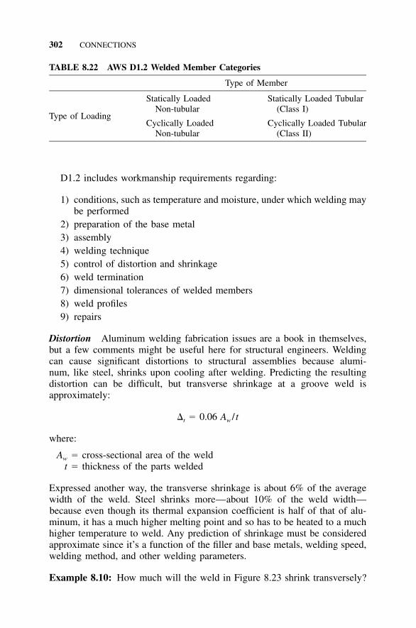
302 CONNECTIONS
TABLE 8.22 AWS D1.2 Welded Member Categories
Type of Member
Type of Loading
Statically LoadedNon-tubular
Cyclically LoadedNon-tubular
Statically Loaded Tubular(Class I)
Cyclically Loaded Tubular(Class II)
D1.2 includes workmanship requirements regarding:
1) conditions, such as temperature and moisture, under which welding maybe performed
2) preparation of the base metal3) assembly4) welding technique5) control of distortion and shrinkage6) weld termination7) dimensional tolerances of welded members8) weld profiles9) repairs
Distortion Aluminum welding fabrication issues are a book in themselves,but a few comments might be useful here for structural engineers. Weldingcan cause significant distortions to structural assemblies because alumi-num, like steel, shrinks upon cooling after welding. Predicting the resultingdistortion can be difficult, but transverse shrinkage at a groove weld isapproximately:
� � 0.06 A / tt w
where:
Aw � cross-sectional area of the weldt � thickness of the parts welded
Expressed another way, the transverse shrinkage is about 6% of the averagewidth of the weld. Steel shrinks more—about 10% of the weld width—because even though its thermal expansion coefficient is half of that of alu-minum, it has a much higher melting point and so has to be heated to a muchhigher temperature to weld. Any prediction of shrinkage must be consideredapproximate since it’s a function of the filler and base metals, welding speed,welding method, and other welding parameters.
Example 8.10: How much will the weld in Figure 8.23 shrink transversely?
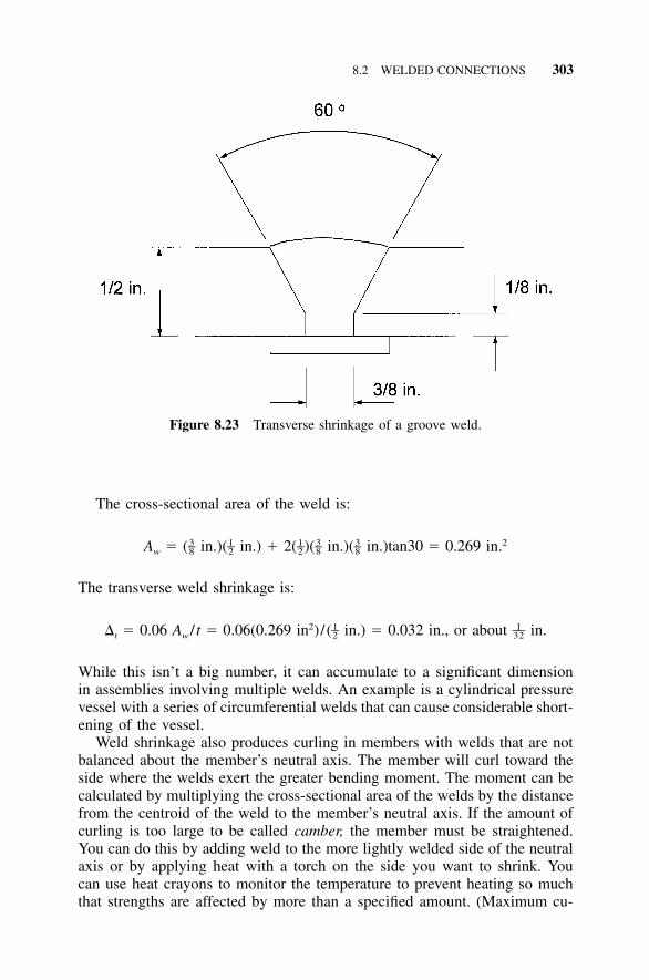
8.2 WELDED CONNECTIONS 303
Figure 8.23 Transverse shrinkage of a groove weld.
The cross-sectional area of the weld is:
3 1 1 3 3 2– – – – –A � ( in.)( in.) � 2( )( in.)( in.)tan30 � 0.269 in.w 8 2 2 8 8
The transverse weld shrinkage is:
2 1 1– ––� � 0.06 A / t � 0.06(0.269 in )/( in.) � 0.032 in., or about in.t w 2 32
While this isn’t a big number, it can accumulate to a significant dimensionin assemblies involving multiple welds. An example is a cylindrical pressurevessel with a series of circumferential welds that can cause considerable short-ening of the vessel.
Weld shrinkage also produces curling in members with welds that are notbalanced about the member’s neutral axis. The member will curl toward theside where the welds exert the greater bending moment. The moment can becalculated by multiplying the cross-sectional area of the welds by the distancefrom the centroid of the weld to the member’s neutral axis. If the amount ofcurling is too large to be called camber, the member must be straightened.You can do this by adding weld to the more lightly welded side of the neutralaxis or by applying heat with a torch on the side you want to shrink. Youcan use heat crayons to monitor the temperature to prevent heating so muchthat strengths are affected by more than a specified amount. (Maximum cu-
304 CONNECTIONS
mulative times at elevated temperatures for some common alloys shown inTable 8.23 will result in no more than a 5% loss in strength.) Because weldingon the opposite side will affect strengths, you must account for this in thedesign. You can perform either of these methods while loading or constrainingthe member.
8.2.6 Weld Quality Assurance
Long before quality became the latest business fad, quality assurance was animportant issue in welding. It still is. This is because the strength of weld-ments is subject to such great variability depending on the care taken in theirproduction. In this sense, weldments are like concrete. The strength of con-crete in place can vary greatly depending on how it was installed. For ex-ample, too much water added to the mix can render the best concrete designflawed. Mill-produced shapes of steel and aluminum, on the other hand, typ-ically exceed minimum strength requirements quite consistently. Furthermore,while careful visual inspection of weldments is useful, visual inspection aloneis very limited in the kinds of defects (euphemistically called discontinuities)that it detects.
AWS D1.2 requires, for each type of weld, that the fabricator:
1) Prepare a written welding procedure specification.2) Qualify this procedure.3) Qualify the welders by testing their work before they are allowed to do
any production welding.4) Maintain records of each of these steps.
Aluminum and steel welding differ significantly in that AWS D1.2 does notallow prequalified joint details and welding procedures for aluminum. This isbecause of the wide range of aluminum welding conditions and alloys allowedunder the D1.2 code. Therefore, all aluminum joint details and welding pro-cedures must be individually qualified. AWS D1.2 Annex B includes somerecommended aluminum joint details for partial and complete joint penetra-tion groove welds. D1.2 Annex E includes sample forms for welding proce-dure specifications (WPS), procedure qualification records (PQR), and man-ufacturers’ records of welder qualification tests. An example of a WPS isAWS B2.1.015, a standard welding procedure specification for TIG welding10 through 18 gauge aluminum sheet (89).
Inspection Methods and Acceptance Criteria It may surprise you to learnthat neither the Aluminum Specification nor the AWS D1.2 code it referencesrequires any inspection of production welds other than visual. Other than therequirements on procedure and welder qualification, workmanship, and visual
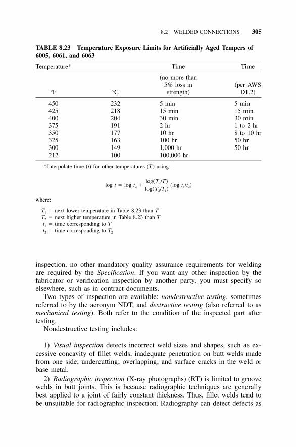
8.2 WELDED CONNECTIONS 305
TABLE 8.23 Temperature Exposure Limits for Artificially Aged Tempers of6005, 6061, and 6063
Temperature* Time Time
�F �C
(no more than5% loss instrength)
(per AWSD1.2)
450 232 5 min 5 min425 218 15 min 15 min400 204 30 min 30 min375 191 2 hr 1 to 2 hr350 177 10 hr 8 to 10 hr325 163 100 hr 50 hr300 149 1,000 hr 50 hr212 100 100,000 hr
*Interpolate time (t) for other temperatures (T ) using:
log(T /T )2log t � log t � (log t /t )2 1 2log(T /T )2 1
where:
T1 � next lower temperature in Table 8.23 than TT2 � next higher temperature in Table 8.23 than Tt1 � time corresponding to T1
t2 � time corresponding to T2
inspection, no other mandatory quality assurance requirements for weldingare required by the Specification. If you want any other inspection by thefabricator or verification inspection by another party, you must specify soelsewhere, such as in contract documents.
Two types of inspection are available: nondestructive testing, sometimesreferred to by the acronym NDT, and destructive testing (also referred to asmechanical testing). Both refer to the condition of the inspected part aftertesting.
Nondestructive testing includes:
1) Visual inspection detects incorrect weld sizes and shapes, such as ex-cessive concavity of fillet welds, inadequate penetration on butt welds madefrom one side; undercutting; overlapping; and surface cracks in the weld orbase metal.
2) Radiographic inspection (X-ray photographs) (RT) is limited to groovewelds in butt joints. This is because radiographic techniques are generallybest applied to a joint of fairly constant thickness. Thus, fillet welds tend tobe unsuitable for radiographic inspection. Radiography can detect defects as
306 CONNECTIONS
small as 2% of the thickness of the weldment, including porosity, internalcracks, lack of fusion, inadequate penetration, and inclusions.
3) Dye-penetrant inspection (PT) may be performed on all types of weldsand joints. The procedure is to apply a penetrating dye, wait 5 to 10 minutes,and then clean the surface. A developer is then applied, and the surface isinspected for evidence of discontinuities revealed by die that has penetratedthem. This method will show only discontinuities that have access to thesurface of the weld. Care should be taken to fully remove any dye or devel-oper before repair welding.
4) Ultrasonic inspection (UT) uses high-frequency sound waves to detectsimilar flaws, but it is expensive and requires trained personnel to interpretthe results. Its advantage over radiography is that it is better suited to detectingthin planar defects parallel to the X-ray beam. Ultrasonic inspection is limitedto groove welds, and D1.2 does not include ultrasonic inspection methods oracceptance criteria. Therefore, when ultrasonic testing is required, the pro-cedure, such as ASTM E164, Standard Recommended Practice for UltrasonicContact Examination of Weldments, and acceptance criteria must be specified.
Destructive testing, such as bend tests, tension tests, and fracture tests, areusually reserved for qualifying welders or weld procedures. They can also beused on production weldments if you don’t mind making a few extra.
307
9 Special Topics
9.1 WELDED MEMBERS
Welding aluminum members introduces a consideration that doesn’t get muchthought for steel: the effect of welding on the strength of the base metal. (Inhindsight, after the cracking of welded steel frames in the Northridge earth-quake, we realized we probably should have been giving this more thought.)Sometimes it’s just too easy to call for joints to be welded to the hilt to avoidthe need to design and detail bolted connections. But the ‘‘less is more’’maxim applies to aluminum welding. Not only does welding tend to causedistortions, it significantly reduces the strength of the aluminum base metal.
The prerequisite for this section is an understanding of the behavior ofaluminum that’s not welded. Once you’re comfortable with that, you’re readyto see what welding changes. This section covers only the design of weldedaluminum members. Section 8.2 addresses the structural design of weldedaluminum connections.
9.1.1 What Welding Does to Aluminum
The heat of welding reduces yield and ultimate strengths of aluminum alloysthat get their strength from artificial aging and those that derive their strengthfrom cold-working. (That just about covers all of the tempers you’re everlikely to use.) In other words, welding offsets the strength the producersworked so hard, by one means or the other, to get into the metal. How muchthe strength is reduced depends on whether the alloy was artificially aged orcold-worked. Cold-worked alloys—(those with an -H in the suffix)—are re-duced to the annealed condition (-O temper), their weakest state. Heat-treatedalloys—(those with a -T in the suffix)—fare a little better, but not by much:their post-welded strength is slightly greater than their solution-heat-treatedstrength (-T4 temper). The effect is illustrated in Figure 9.1 for one alloyfrom each of these two groups. On the other hand, welding does not affectthe modulus of elasticity (E).
This reduction in strength is apart from any effect from the strength of thefiller weld alloy; even a filler stronger than the base metal, as is common insteel, doesn’t help. That’s because the heat of welding is the culprit. Ofcourse, if the filler metal in the weld is weaker than the reduced strength basemetal, the strength of the weld will be reduced even further. But if you selectyour filler from the ones in Aluminum Specification Table 7.2-1 (and not an
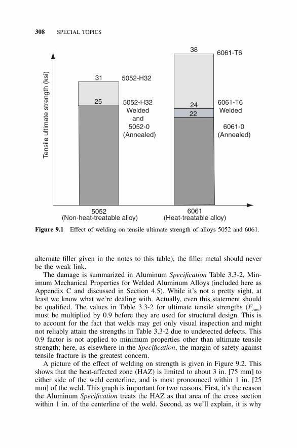
308 SPECIAL TOPICS
5052(Non-heat-treatable alloy)
6061(Heat-treatable alloy)
5052-H32 Welded and 5052-0(Annealed)
6061-T6 Welded
6061-0(Annealed)
6061-T638
5052-H3231
25 2422
Tens
ile u
ltim
ate
stre
ngth
(ks
i)
Figure 9.1 Effect of welding on tensile ultimate strength of alloys 5052 and 6061.
alternate filler given in the notes to this table), the filler metal should neverbe the weak link.
The damage is summarized in Aluminum Specification Table 3.3-2, Min-imum Mechanical Properties for Welded Aluminum Alloys (included here asAppendix C and discussed in Section 4.5). While it’s not a pretty sight, atleast we know what we’re dealing with. Actually, even this statement shouldbe qualified. The values in Table 3.3-2 for ultimate tensile strengths (Ftuw)must be multiplied by 0.9 before they are used for structural design. This isto account for the fact that welds may get only visual inspection and mightnot reliably attain the strengths in Table 3.3-2 due to undetected defects. This0.9 factor is not applied to minimum properties other than ultimate tensilestrength; here, as elsewhere in the Specification, the margin of safety againsttensile fracture is the greatest concern.
A picture of the effect of welding on strength is given in Figure 9.2. Thisshows that the heat-affected zone (HAZ) is limited to about 3 in. [75 mm] toeither side of the weld centerline, and is most pronounced within 1 in. [25mm] of the weld. This graph is important for two reasons. First, it’s the reasonthe Aluminum Specification treats the HAZ as that area of the cross sectionwithin 1 in. of the centerline of the weld. Second, as we’ll explain, it is why
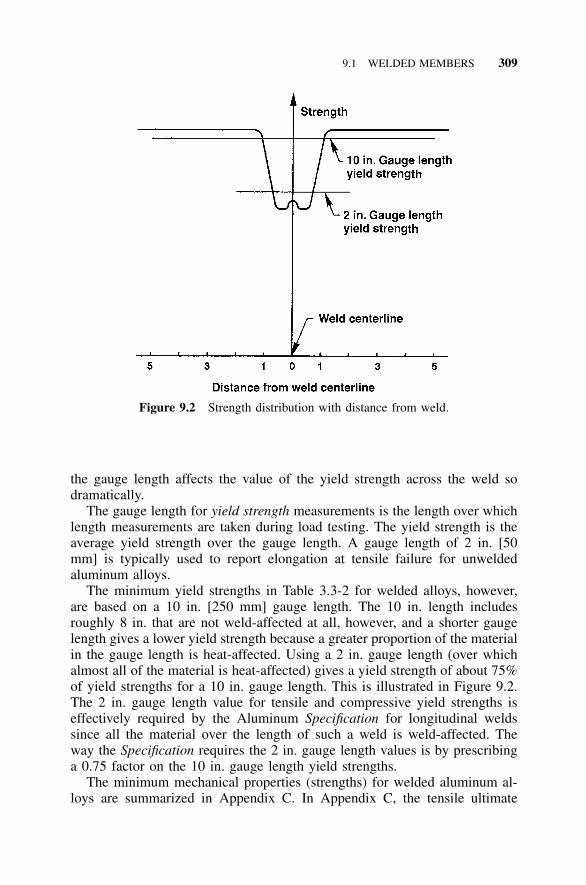
9.1 WELDED MEMBERS 309
Figure 9.2 Strength distribution with distance from weld.
the gauge length affects the value of the yield strength across the weld sodramatically.
The gauge length for yield strength measurements is the length over whichlength measurements are taken during load testing. The yield strength is theaverage yield strength over the gauge length. A gauge length of 2 in. [50mm] is typically used to report elongation at tensile failure for unweldedaluminum alloys.
The minimum yield strengths in Table 3.3-2 for welded alloys, however,are based on a 10 in. [250 mm] gauge length. The 10 in. length includesroughly 8 in. that are not weld-affected at all, however, and a shorter gaugelength gives a lower yield strength because a greater proportion of the materialin the gauge length is heat-affected. Using a 2 in. gauge length (over whichalmost all of the material is heat-affected) gives a yield strength of about 75%of yield strengths for a 10 in. gauge length. This is illustrated in Figure 9.2.The 2 in. gauge length value for tensile and compressive yield strengths iseffectively required by the Aluminum Specification for longitudinal weldssince all the material over the length of such a weld is weld-affected. Theway the Specification requires the 2 in. gauge length values is by prescribinga 0.75 factor on the 10 in. gauge length yield strengths.
The minimum mechanical properties (strengths) for welded aluminum al-loys are summarized in Appendix C. In Appendix C, the tensile ultimate

310 SPECIAL TOPICS
Figure 9.3 Transverse weld.
strengths have been factored by 0.9 from those given in Aluminum Specifi-cation Table 3.3-2, and the tensile and compressive yield strengths have beenfactored by 0.75 from those given in Table 3.3-2 for the reasons cited aboveso that they may be used directly for structural calculations. One more sub-tlety: if the welded compressive yield strength (Fcyw) exceeds 90% of theunwelded compressive yield strength (Fcy), then the unwelded compressiveyield strength may be used to compute allowable compressive stresses in theweld-affected area. In this case, the welded material has properties closeenough to the unwelded material that the Specification allows you to ignorethe slight difference in strength. Other than annealed tempers, this rule windsup applying only to 5086-H111 and 5454-H111 extrusions (which are rarelyused), so it doesn’t warrant a lot of attention. If you’re starting with annealed(-O temper) base metal before welding, of course, then the welded strengthsare the same as the unwelded strengths, and welding has no effect on design.Aluminum structures that are going to be heavily welded, such as pressurevessels, are often made of annealed material because for design purposes, thematerial is going to wind up annealed at the end of fabrication anyway.
9.1.2 Types of Welded Members
The effect of welding on member strength depends, in part, on the orientationof the weld with respect to the length of the member. Welds, therefore, aredivided into two types for the purpose of divining their influence on memberstrength: transverse welds and longitudinal welds.
Transverse welds are those lying in a plane transverse to the long axis ofthe member. Examples of transverse welds are a groove weld at a splice inthe length of a member, and the weld attaching a base plate to a column(Figure 9.3). Welds made at connections are often transverse welds.
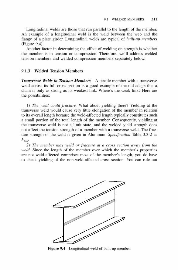
9.1 WELDED MEMBERS 311
Figure 9.4 Longitudinal weld of built-up member.
Longitudinal welds are those that run parallel to the length of the member.An example of a longitudinal weld is the weld between the web and theflange of a plate girder. Longitudinal welds are typical of built-up members(Figure 9.4).
Another factor in determining the effect of welding on strength is whetherthe member is in tension or compression. Therefore, we’ll address weldedtension members and welded compression members separately below.
9.1.3 Welded Tension Members
Transverse Welds in Tension Members A tensile member with a transverseweld across its full cross section is a good example of the old adage that achain is only as strong as its weakest link. Where’s the weak link? Here arethe possibilities:
1) The weld could fracture. What about yielding there? Yielding at thetransverse weld would cause very little elongation of the member in relationto its overall length because the weld-affected length typically constitutes sucha small portion of the total length of the member. Consequently, yielding atthe transverse weld is not a limit state, and the welded yield strength doesnot affect the tension strength of a member with a transverse weld. The frac-ture strength of the weld is given in Aluminum Specification Table 3.3-2 asFtuw.
2) The member may yield or fracture at a cross section away from theweld. Since the length of the member over which the member’s propertiesare not weld-affected comprises most of the member’s length, you do haveto check yielding of the non-weld-affected cross section. You can rule out
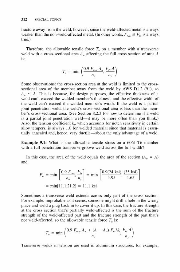
312 SPECIAL TOPICS
fracture away from the weld, however, since the weld-affected metal is alwaysweaker than the non-weld-affected metal. (In other words, Ftuw � Ftu is alwaystrue.)
Therefore, the allowable tensile force Ta on a member with a transverseweld with a cross-sectional area Aw affecting the full cross section of area Ais:
F A0.9 F A tytuw wT � min ,� �a n nu y
Some observations: the cross-section area at the weld is limited to the cross-sectional area of the member away from the weld by AWS D1.2 (91), soAw � A. This is because, for design purposes, the effective thickness of aweld can’t exceed the welded member’s thickness, and the effective width ofthe weld can’t exceed the welded member’s width. If the weld is a partialjoint penetration weld, the weld’s cross-sectional area is less than the mem-ber’s cross-sectional area. (See Section 8.2.3 for how to determine if a weldis a partial joint penetration weld—it may be more often than you think.)Also, the tension coefficient kt, which accounts for notch sensitivity in certainalloy tempers, is always 1.0 for welded material since that material is essen-tially annealed and, hence, very ductile—about the only advantage of a weld.
Example 9.1: What is the allowable tensile stress on a 6061-T6 memberwith a full penetration transverse groove weld across the full width?
In this case, the area of the weld equals the area of the section (Aw � A)and
F0.9 F 0.9(24 ksi) (35 ksi)tytuwF � min , � min ,� � � �w n n 1.95 1.65u y
� min[11.1,21.2] � 11.1 ksi
Sometimes a transverse weld extends across only part of the cross section.For example, improbable as it seems, someone might drill a hole in the wrongplace and weld a plug back in to cover it up. In this case, the fracture strengthat the cross section that’s partially weld-affected is the sum of the fracturestrength of the weld-affected part and the fracture strength of the part that’snot weld-affected, so the allowable tensile force Ta is:
F A0.9 F A � (A � A ) F /k tytuw w w tu tT � min ,� �a n nu y
Transverse welds in tension are used in aluminum structures, for example,
9.1 WELDED MEMBERS 313
the vertical welds on cylindrical tanks storing liquids, but such structures areusually subject to special inspection methods as discussed briefly in Section3.3. Because the integrity of these welded structures are so dependent on thereliability of these welds, special standards have typically been developed ineach industry that uses this type of construction. ASME Standard B96.1,Welded Aluminum-Alloy Storage Tanks (85), as one example, requires a jointfactor less than 1.0 be applied to such welds that have not been fully radio-graphed. Additional requirements apply to the certification of the welder andthe weld and weld repair procedures. You’ll need to consult the appropriatecodes for additional design considerations for structures that rely on trans-verse welds in tension.
Longitudinal Welds in Tension Members Longitudinal welds in tensilemembers (in axial tension or bending tension) are treated with a weighted-average approach. The formula for allowable stress is, therefore,
F � F � (A /A)(F � F ) (9.1)pw n w n w
where: Fpw � allowable stress on a cross section, part of whose area lieswithin 1.0 in. [25 mm] of a weld
Fn � allowable stress for the cross section if none of it were weld-affected
Fw � allowable stress for the cross section if the entire cross sectionwere weld-affected. For ultimate tensile strength, use 0.9Ftuw
and for tensile yield strength use 0.75Ftyw to calculate Fw.Aw � portion of the area of the cross section lying within 1.0 in. [25
mm] of the centerline of a groove weld or the heel of a filletweld
A � net area of the cross section (for axial tension) or the tensionflange (for beams). For this purpose, the flange is that portionof the section farther than 2c /3 from the neutral axis, wherec � the distance from the neutral axis to the extreme fiber.
The weighted-average approach means that the strengths of the unaffectedportion of the section and the weld-affected portion of the section areweighted in proportion to their share of the full cross section. One simplifi-cation is used: If the weld-affected portion of the cross section is less than15%, the strength reduction from welding is deemed too small to worry about,and the effect of welding can be neglected. (See Aluminum SpecificationSection 7.1.2.) The inaccuracy introduced by this simplification is on the orderof 5%.
Example 9.2: What is the allowable axial tensile stress for the member withthe cross section shown in Figure 9.5? The member is 6061-T6 welded with4043 filler alloy.
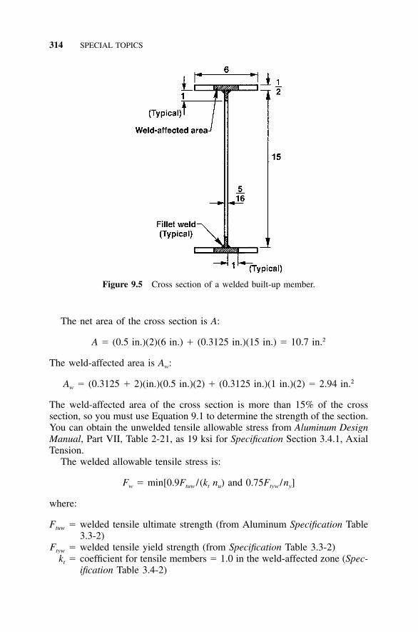
314 SPECIAL TOPICS
Figure 9.5 Cross section of a welded built-up member.
The net area of the cross section is A:
2A � (0.5 in.)(2)(6 in.) � (0.3125 in.)(15 in.) � 10.7 in.
The weld-affected area is Aw:
2A � (0.3125 � 2)(in.)(0.5 in.)(2) � (0.3125 in.)(1 in.)(2) � 2.94 in.w
The weld-affected area of the cross section is more than 15% of the crosssection, so you must use Equation 9.1 to determine the strength of the section.You can obtain the unwelded tensile allowable stress from Aluminum DesignManual, Part VII, Table 2-21, as 19 ksi for Specification Section 3.4.1, AxialTension.
The welded allowable tensile stress is:
F � min[0.9F / (k n ) and 0.75F /n ]w tuw t u tyw y
where:
Ftuw � welded tensile ultimate strength (from Aluminum Specification Table3.3-2)
Ftyw � welded tensile yield strength (from Specification Table 3.3-2)kt � coefficient for tensile members � 1.0 in the weld-affected zone (Spec-
ification Table 3.4-2)
9.1 WELDED MEMBERS 315
nu � safety factor on ultimate � 1.95ny � safety factor on yield � 1.65.
Note that Ftyw is 15 ksi rather than 20 ksi because the flange plate thicknessis greater than 0.375 in. and 4043 filler alloy is used. This gives:
F � min[0.9(24 ksi) /[(1.0)(1.95)] and 0.75(15 ksi)/1.65]w
F � min[11.1 ksi, 6.8 ksi] � 6.8 ksiw
Calculating the allowable stress for the partially weld-affected section (Fpw)using Equation 9.1:
F � 19 � (2.94/10.7)(19 � 6.8) � 15.6 ksipw
9.1.4 Welded Compression Members
Transverse Welds in Compression Members For beams or columns sup-ported at both ends and with a transverse weld within 5% of the length ofthe member from an end, Aluminum Specification Section 7.1.1 allows youto neglect the effect of welding on the member as long as you consider themember to be pin-ended. An example is a column in a building frame witha welded base plate.
For all other beams and columns with transverse welds, the AluminumSpecification requires that the member be designed as if the entire memberwere weld-affected, even if the transverse weld is only at one point along themember length. You calculate the strength by substituting 0.75Fcyw for Fcy inthe equations for strength (in Aluminum Specification Table 3.4-3), and inthe equations for the buckling constants (B, D, and C). As discussed above,the equations to be used for buckling constants are those for non-artificiallyaged alloys (Specification Table 3.3-3, not Table 3.3-4), even if the weldedalloy in question was artificially aged before welding.
Example 9.3: What is the allowable compressive stress for the cross sectionof Example 9.2 as an axially loaded column with a transverse weld at itsmidheight and a slenderness ratio (kL/r) of 30?
In accordance with Aluminum Specification Section 7.1.3, since the weldis farther than 5% of the member length from the member ends, the columnis to be treated as if the entire column were weld-affected. The compressiveyield strength is 0.75(15 ksi) � 11 ksi (see Table 3.3-2). The allowable stressfor columns with a slenderness ratio less than slenderness limit S1 is:
316 SPECIAL TOPICS
F � F /n � (11 ksi) /1.65 � 6.7 ksi (9.2)w cy y
The allowable stress for columns with a slenderness ratio between slendernesslimits S1 and S2 is:
F � (B � D (kL/r)) /n (9.3)w c c u
where Bc, Dc � buckling constants calculated from Table 3.3-3 using 11 ksifor Fcy.
Calculation of the buckling constants for the welded column requires theuse of Table 3.3-3, which is for unwelded tempers -T1 through -T4 and allwelded alloys, rather than Table 3.3-4, which is for unwelded tempers -T5through -T9, even though the alloy is of -T6 temper:
1 / 2 1 / 2F 11cyB � F 1 � � 11 1 � � 12.2 ksi� � � � � � � �c cy 1000 10001 / 2 1 / 2B 6B 12.2 6(12.2)c cD � � � 0.052 ksi� � � �c 20 E 20 10,100
So, the allowable stress is:
F � 12.2/1.95 � (0.052/1.95)(kL/r) � 6.3 � 0.027 (kL/r)w
The allowable stress for columns with a slenderness ratio greater than S2 is:
2 2 2 2 2F � � E / [(n )(kL/r) ] � � (10,100)/(1.95)(kL/r) � 51,100/(kL/r)w u
(9.4)
To determine which of Equations 9.2, 9.3, and 9.4 to use for this member,we need to determine the slenderness limit S2:
2B 2(12.2)cS � C � � � 1572 c 3D 3(0.052)c
Since the slenderness ratio is 30, which is less than S2 � 157, the allowablestress is given by the inelastic buckling equation (Equation 9.3):
F � 6.3 � 0.027(30) � 5.5 ksi.w
This example illustrates how tedious it is to calculate the strength of weldedcompression members. Most of the work lies in calculating the welded buck-ling constants. For non-welded members, the buckling constants are given inAluminum Design Manual, Part VII, Table 2-1, but buckling constants for
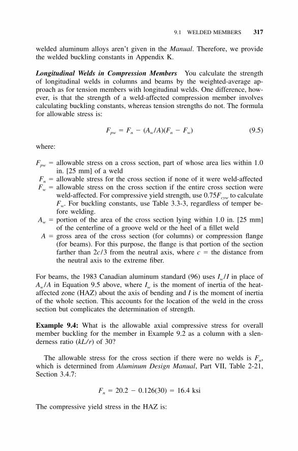
9.1 WELDED MEMBERS 317
welded aluminum alloys aren’t given in the Manual. Therefore, we providethe welded buckling constants in Appendix K.
Longitudinal Welds in Compression Members You calculate the strengthof longitudinal welds in columns and beams by the weighted-average ap-proach as for tension members with longitudinal welds. One difference, how-ever, is that the strength of a weld-affected compression member involvescalculating buckling constants, whereas tension strengths do not. The formulafor allowable stress is:
F � F � (A /A)(F � F ) (9.5)pw n w n w
where:
Fpw � allowable stress on a cross section, part of whose area lies within 1.0in. [25 mm] of a weld
Fn � allowable stress for the cross section if none of it were weld-affectedFw � allowable stress on the cross section if the entire cross section were
weld-affected. For compressive yield strength, use 0.75Fcyw to calculateFw. For buckling constants, use Table 3.3-3, regardless of temper be-fore welding.
Aw � portion of the area of the cross section lying within 1.0 in. [25 mm]of the centerline of a groove weld or the heel of a fillet weld
A � gross area of the cross section (for columns) or compression flange(for beams). For this purpose, the flange is that portion of the sectionfarther than 2c /3 from the neutral axis, where c � the distance fromthe neutral axis to the extreme fiber.
For beams, the 1983 Canadian aluminum standard (96) uses Iw /I in place ofAw /A in Equation 9.5 above, where Iw is the moment of inertia of the heat-affected zone (HAZ) about the axis of bending and I is the moment of inertiaof the whole section. This accounts for the location of the weld in the crosssection but complicates the determination of strength.
Example 9.4: What is the allowable axial compressive stress for overallmember buckling for the member in Example 9.2 as a column with a slen-derness ratio (kL/r) of 30?
The allowable stress for the cross section if there were no welds is Fn,which is determined from Aluminum Design Manual, Part VII, Table 2-21,Section 3.4.7:
F � 20.2 � 0.126(30) � 16.4 ksin
The compressive yield stress in the HAZ is:
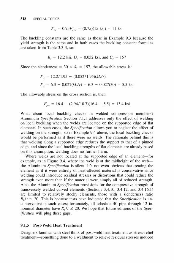
318 SPECIAL TOPICS
F � 0.75F � (0.75)(15 ksi) � 11 ksicy cyw
The buckling constants are the same as those in Example 9.3 because theyield strength is the same and in both cases the buckling constant formulasare taken from Table 3.3-3, so:
B � 12.2 ksi, D � 0.052 ksi, and C � 157c c c
Since the slenderness � 30 � S2 � 157, the allowable stress is:
F � 12.2/1.95 � (0.052/1.95)(kL/r)w
F � 6.3 � 0.027(kL/r) � 6.3 � 0.027(30) � 5.5 ksiw
The allowable stress on the cross section is, then:
F � 16.4 � (2.94/10.7)(16.4 � 5.5) � 13.4 ksipw
What about local buckling checks in welded compression members?Aluminum Specification Section 7.1.1 addresses only the effect of weldingon local buckling when the welds are located on the supported edge of flatelements. In such cases, the Specification allows you to neglect the effect ofwelding on the strength, so in Example 9.4 above, the local buckling checkswould be performed as if there were no welds. The rationale behind this isthat welding along a supported edge reduces the support to that of a pinnededge, and since the local buckling strengths of flat elements are already basedon this assumption, welding does no further harm.
Where welds are not located at the supported edge of an element—forexample, as in Figure 9.4, where the weld is at the midheight of the web—the Aluminum Specification is silent. It’s not even obvious that treating theelement as if it were entirely of heat-affected material is conservative sincewelding could introduce residual stresses or distortions that could reduce thestrength even more than if the material were simply all of reduced strength.Also, the Aluminum Specification provisions for the compressive strength oftransversely welded curved elements (Sections 3.4.10, 3.4.12, and 3.4.16.1)are limited to relatively stocky elements, those with a slenderness ratioRb / t � 20. This is because tests have indicated that the Specification is un-conservative in such cases; fortunately, all schedule 40 pipe through 12 in.nominal diameter have Rb / t � 20. We hope that future editions of the Spec-ification will plug these gaps.
9.1.5 Post-Weld Heat Treatment
Designers familiar with steel think of post-weld heat treatment as stress-relieftreatment—something done to a weldment to relieve residual stresses induced
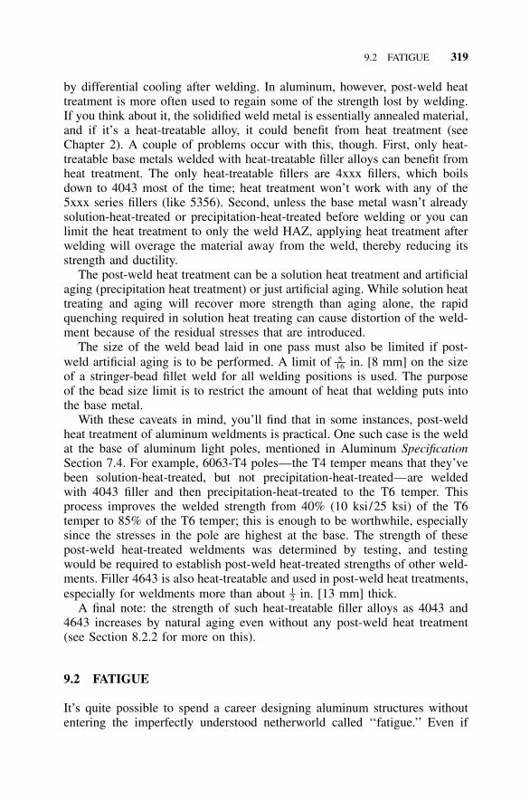
9.2 FATIGUE 319
by differential cooling after welding. In aluminum, however, post-weld heattreatment is more often used to regain some of the strength lost by welding.If you think about it, the solidified weld metal is essentially annealed material,and if it’s a heat-treatable alloy, it could benefit from heat treatment (seeChapter 2). A couple of problems occur with this, though. First, only heat-treatable base metals welded with heat-treatable filler alloys can benefit fromheat treatment. The only heat-treatable fillers are 4xxx fillers, which boilsdown to 4043 most of the time; heat treatment won’t work with any of the5xxx series fillers (like 5356). Second, unless the base metal wasn’t alreadysolution-heat-treated or precipitation-heat-treated before welding or you canlimit the heat treatment to only the weld HAZ, applying heat treatment afterwelding will overage the material away from the weld, thereby reducing itsstrength and ductility.
The post-weld heat treatment can be a solution heat treatment and artificialaging (precipitation heat treatment) or just artificial aging. While solution heattreating and aging will recover more strength than aging alone, the rapidquenching required in solution heat treating can cause distortion of the weld-ment because of the residual stresses that are introduced.
The size of the weld bead laid in one pass must also be limited if post-weld artificial aging is to be performed. A limit of in. [8 mm] on the size5––16
of a stringer-bead fillet weld for all welding positions is used. The purposeof the bead size limit is to restrict the amount of heat that welding puts intothe base metal.
With these caveats in mind, you’ll find that in some instances, post-weldheat treatment of aluminum weldments is practical. One such case is the weldat the base of aluminum light poles, mentioned in Aluminum SpecificationSection 7.4. For example, 6063-T4 poles—the T4 temper means that they’vebeen solution-heat-treated, but not precipitation-heat-treated—are weldedwith 4043 filler and then precipitation-heat-treated to the T6 temper. Thisprocess improves the welded strength from 40% (10 ksi/25 ksi) of the T6temper to 85% of the T6 temper; this is enough to be worthwhile, especiallysince the stresses in the pole are highest at the base. The strength of thesepost-weld heat-treated weldments was determined by testing, and testingwould be required to establish post-weld heat-treated strengths of other weld-ments. Filler 4643 is also heat-treatable and used in post-weld heat treatments,especially for weldments more than about in. [13 mm] thick.1–2
A final note: the strength of such heat-treatable filler alloys as 4043 and4643 increases by natural aging even without any post-weld heat treatment(see Section 8.2.2 for more on this).
9.2 FATIGUE
It’s quite possible to spend a career designing aluminum structures withoutentering the imperfectly understood netherworld called ‘‘fatigue.’’ Even if
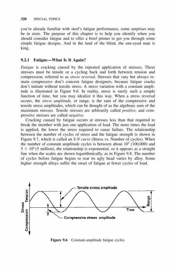
320 SPECIAL TOPICS
Figure 9.6 Constant-amplitude fatigue cycles.
you’re already familiar with steel’s fatigue performance, some surprises maybe in store. The purpose of this chapter is to help you identify when youshould consider fatigue and to offer a brief primer to get you through somesimple fatigue designs. And in the land of the blind, the one-eyed man isking.
9.2.1 Fatigue—What Is It Again?
Fatigue is cracking caused by the repeated application of stresses. Thesestresses must be tensile or a cycling back and forth between tension andcompression, referred to as stress reversal. Stresses that vary but always re-main compressive don’t concern fatigue designers, because fatigue cracksdon’t initiate without tensile stress. A stress variation with a constant ampli-tude is illustrated in Figure 9.6. In reality, stress is rarely such a simplefunction of time, but you may idealize it this way. When a stress reversaloccurs, the stress amplitude, or range, is the sum of the compressive andtensile stress amplitudes, which can be thought of as the algebraic sum of themaximum stresses. Tensile stresses are arbitrarily called positive, and com-pressive stresses are called negative.
Cracking caused by fatigue occurs at stresses less than that required tobreak the member with just one application of load. The more times the loadis applied, the lower the stress required to cause failure. The relationshipbetween the number of cycles of stress and the fatigue strength is shown inFigure 9.7, which is called an S-N curve (Stress vs. Number of cycles). Whenthe number of constant amplitude cycles is between about 105 (100,000) and5 � 106 (5 million), the relationship is exponential, so it appears as a straightline when the scales are shown logarithmically, as in Figure 9.8. The numberof cycles before fatigue begins to rear its ugly head varies by alloy. Somehigher strength alloys suffer the onset of fatigue at fewer cycles of load.
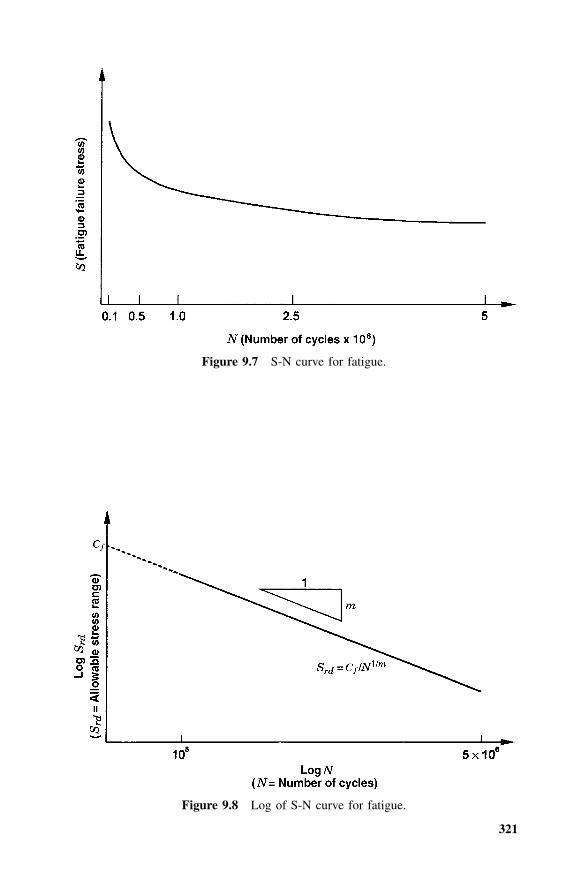
321
Figure 9.7 S-N curve for fatigue.
Figure 9.8 Log of S-N curve for fatigue.
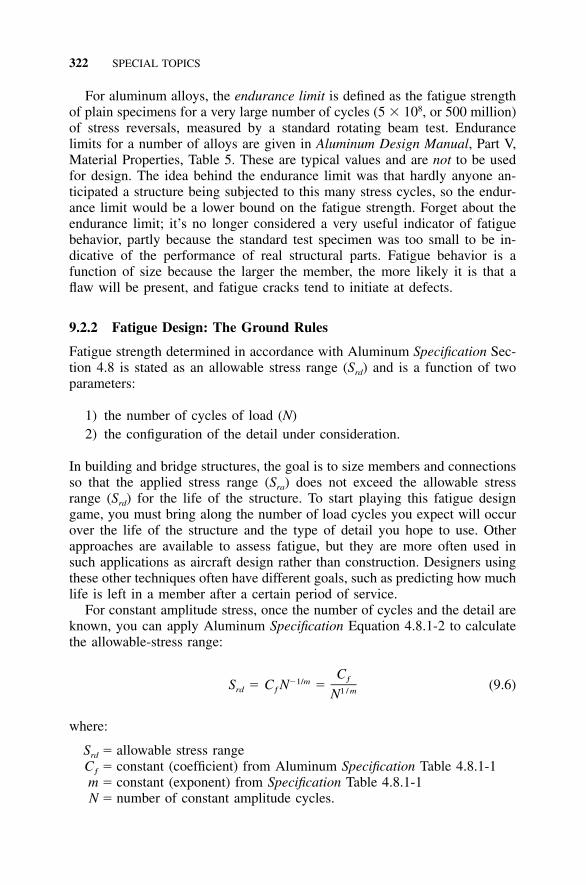
322 SPECIAL TOPICS
For aluminum alloys, the endurance limit is defined as the fatigue strengthof plain specimens for a very large number of cycles (5 � 108, or 500 million)of stress reversals, measured by a standard rotating beam test. Endurancelimits for a number of alloys are given in Aluminum Design Manual, Part V,Material Properties, Table 5. These are typical values and are not to be usedfor design. The idea behind the endurance limit was that hardly anyone an-ticipated a structure being subjected to this many stress cycles, so the endur-ance limit would be a lower bound on the fatigue strength. Forget about theendurance limit; it’s no longer considered a very useful indicator of fatiguebehavior, partly because the standard test specimen was too small to be in-dicative of the performance of real structural parts. Fatigue behavior is afunction of size because the larger the member, the more likely it is that aflaw will be present, and fatigue cracks tend to initiate at defects.
9.2.2 Fatigue Design: The Ground Rules
Fatigue strength determined in accordance with Aluminum Specification Sec-tion 4.8 is stated as an allowable stress range (Srd) and is a function of twoparameters:
1) the number of cycles of load (N)2) the configuration of the detail under consideration.
In building and bridge structures, the goal is to size members and connectionsso that the applied stress range (Sra) does not exceed the allowable stressrange (Srd) for the life of the structure. To start playing this fatigue designgame, you must bring along the number of load cycles you expect will occurover the life of the structure and the type of detail you hope to use. Otherapproaches are available to assess fatigue, but they are more often used insuch applications as aircraft design rather than construction. Designers usingthese other techniques often have different goals, such as predicting how muchlife is left in a member after a certain period of service.
For constant amplitude stress, once the number of cycles and the detail areknown, you can apply Aluminum Specification Equation 4.8.1-2 to calculatethe allowable-stress range:
Cƒ�1/mS � C N � (9.6)rd ƒ 1 / mN
where:
Srd � allowable stress rangeCƒ � constant (coefficient) from Aluminum Specification Table 4.8.1-1m � constant (exponent) from Specification Table 4.8.1-1N � number of constant amplitude cycles.
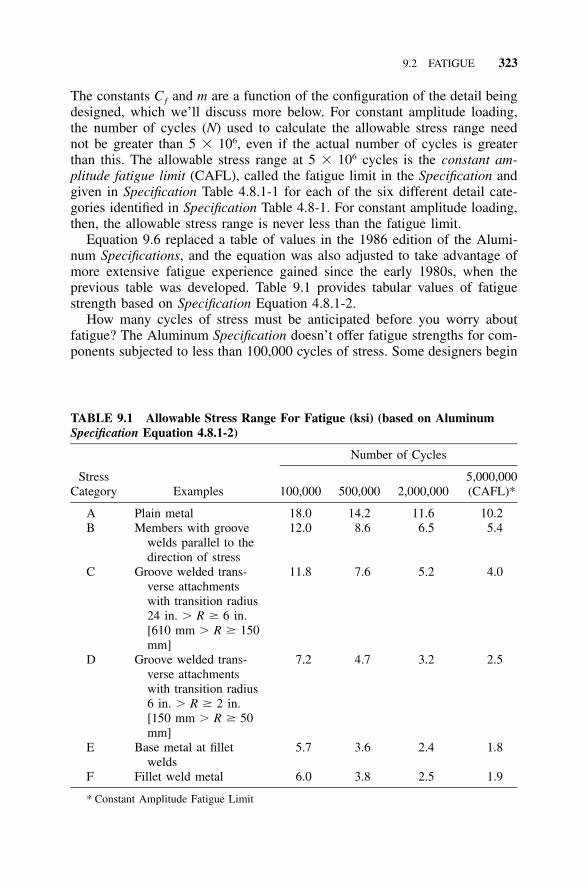
9.2 FATIGUE 323
TABLE 9.1 Allowable Stress Range For Fatigue (ksi) (based on AluminumSpecification Equation 4.8.1-2)
StressCategory Examples
Number of Cycles
100,000 500,000 2,000,0005,000,000(CAFL)*
A Plain metal 18.0 14.2 11.6 10.2B Members with groove
welds parallel to thedirection of stress
12.0 8.6 6.5 5.4
C Groove welded trans-verse attachmentswith transition radius24 in. � R � 6 in.[610 mm � R � 150mm]
11.8 7.6 5.2 4.0
D Groove welded trans-verse attachmentswith transition radius6 in. � R � 2 in.[150 mm � R � 50mm]
7.2 4.7 3.2 2.5
E Base metal at filletwelds
5.7 3.6 2.4 1.8
F Fillet weld metal 6.0 3.8 2.5 1.9
* Constant Amplitude Fatigue Limit
The constants Cƒ and m are a function of the configuration of the detail beingdesigned, which we’ll discuss more below. For constant amplitude loading,the number of cycles (N) used to calculate the allowable stress range neednot be greater than 5 � 106, even if the actual number of cycles is greaterthan this. The allowable stress range at 5 � 106 cycles is the constant am-plitude fatigue limit (CAFL), called the fatigue limit in the Specification andgiven in Specification Table 4.8.1-1 for each of the six different detail cate-gories identified in Specification Table 4.8-1. For constant amplitude loading,then, the allowable stress range is never less than the fatigue limit.
Equation 9.6 replaced a table of values in the 1986 edition of the Alumi-num Specifications, and the equation was also adjusted to take advantage ofmore extensive fatigue experience gained since the early 1980s, when theprevious table was developed. Table 9.1 provides tabular values of fatiguestrength based on Specification Equation 4.8.1-2.
How many cycles of stress must be anticipated before you worry aboutfatigue? The Aluminum Specification doesn’t offer fatigue strengths for com-ponents subjected to less than 100,000 cycles of stress. Some designers begin
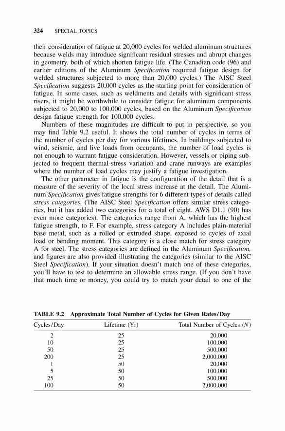
324 SPECIAL TOPICS
TABLE 9.2 Approximate Total Number of Cycles for Given Rates/Day
Cycles /Day Lifetime (Yr) Total Number of Cycles (N )
2 25 20,00010 25 100,00050 25 500,000
200 25 2,000,0001 50 20,0005 50 100,000
25 50 500,000100 50 2,000,000
their consideration of fatigue at 20,000 cycles for welded aluminum structuresbecause welds may introduce significant residual stresses and abrupt changesin geometry, both of which shorten fatigue life. (The Canadian code (96) andearlier editions of the Aluminum Specification required fatigue design forwelded structures subjected to more than 20,000 cycles.) The AISC SteelSpecification suggests 20,000 cycles as the starting point for consideration offatigue. In some cases, such as weldments and details with significant stressrisers, it might be worthwhile to consider fatigue for aluminum componentssubjected to 20,000 to 100,000 cycles, based on the Aluminum Specificationdesign fatigue strength for 100,000 cycles.
Numbers of these magnitudes are difficult to put in perspective, so youmay find Table 9.2 useful. It shows the total number of cycles in terms ofthe number of cycles per day for various lifetimes. In buildings subjected towind, seismic, and live loads from occupants, the number of load cycles isnot enough to warrant fatigue consideration. However, vessels or piping sub-jected to frequent thermal-stress variation and crane runways are exampleswhere the number of load cycles may justify a fatigue investigation.
The other parameter in fatigue is the configuration of the detail that is ameasure of the severity of the local stress increase at the detail. The Alumi-num Specification gives fatigue strengths for 6 different types of details calledstress categories. (The AISC Steel Specification offers similar stress catego-ries, but it has added two categories for a total of eight. AWS D1.1 (90) haseven more categories). The categories range from A, which has the highestfatigue strength, to F. For example, stress category A includes plain-materialbase metal, such as a rolled or extruded shape, exposed to cycles of axialload or bending moment. This category is a close match for stress categoryA for steel. The stress categories are defined in the Aluminum Specification,and figures are also provided illustrating the categories (similar to the AISCSteel Specification). If your situation doesn’t match one of these categories,you’ll have to test to determine an allowable stress range. (If you don’t havethat much time or money, you could try to match your detail to one of the
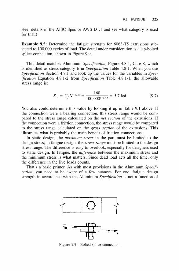
9.2 FATIGUE 325
Figure 9.9 Bolted splice connection.
steel details in the AISC Spec or AWS D1.1 and see what category is usedfor that.)
Example 9.5: Determine the fatigue strength for 6063-T5 extrusions sub-jected to 100,000 cycles of load. The detail under consideration is a lap-boltedsplice connection, shown in Figure 9.9.
This detail matches Aluminum Specification, Figure 4.8-1, Case 8, whichis identified as stress category E in Specification Table 4.8-1. When you useSpecification Section 4.8.1 and look up the values for the variables in Spec-ification Equation 4.8.1-2 from Specification Table 4.8.1-1, the allowablestress range is:
160�1 / mS � C N � � 5.7 ksi (9.7)rd ƒ 1 / 3.45100,000
You also could determine this value by looking it up in Table 9.1 above. Ifthe connection were a bearing connection, this stress range would be com-pared to the stress range calculated on the net section of the extrusions. Ifthe connection were a friction connection, the stress range would be comparedto the stress range calculated on the gross section of the extrusions. Thisillustrates what is probably the main benefit of friction connections.
In static design, the maximum stress in the part must be limited to thedesign stress; in fatigue design, the stress range must be limited to the designstress range. The difference is easy to overlook, especially for designers usedto static design. In fatigue, the difference between the maximum stress andthe minimum stress is what matters. Since dead load acts all the time, onlythe difference in the live loads counts.
That’s a basic primer. As with most provisions in the Aluminum Specifi-cation, you need to be aware of a few nuances. For one, fatigue designstrength in accordance with the Aluminum Specification is not a function of
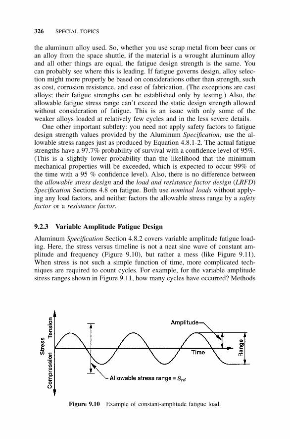
326 SPECIAL TOPICS
Figure 9.10 Example of constant-amplitude fatigue load.
the aluminum alloy used. So, whether you use scrap metal from beer cans oran alloy from the space shuttle, if the material is a wrought aluminum alloyand all other things are equal, the fatigue design strength is the same. Youcan probably see where this is leading. If fatigue governs design, alloy selec-tion might more properly be based on considerations other than strength, suchas cost, corrosion resistance, and ease of fabrication. (The exceptions are castalloys; their fatigue strengths can be established only by testing.) Also, theallowable fatigue stress range can’t exceed the static design strength allowedwithout consideration of fatigue. This is an issue with only some of theweaker alloys loaded at relatively few cycles and in the less severe details.
One other important subtlety: you need not apply safety factors to fatiguedesign strength values provided by the Aluminum Specification; use the al-lowable stress ranges just as produced by Equation 4.8.1-2. The actual fatiguestrengths have a 97.7% probability of survival with a confidence level of 95%.(This is a slightly lower probability than the likelihood that the minimummechanical properties will be exceeded, which is expected to occur 99% ofthe time with a 95 % confidence level). Also, there is no difference betweenthe allowable stress design and the load and resistance factor design (LRFD)Specification Sections 4.8 on fatigue. Both use nominal loads without apply-ing any load factors, and neither factors the allowable stress range by a safetyfactor or a resistance factor.
9.2.3 Variable Amplitude Fatigue Design
Aluminum Specification Section 4.8.2 covers variable amplitude fatigue load-ing. Here, the stress versus timeline is not a neat sine wave of constant am-plitude and frequency (Figure 9.10), but rather a mess (like Figure 9.11).When stress is not such a simple function of time, more complicated tech-niques are required to count cycles. For example, for the variable amplitudestress ranges shown in Figure 9.11, how many cycles have occurred? Methods
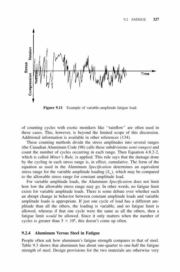
9.2 FATIGUE 327
Figure 9.11 Example of variable-amplitude fatigue load.
of counting cycles with exotic monikers like ‘‘rainflow’’ are often used inthese cases. This, however, is beyond the limited scope of this discussion.Additional information is available in other references (134).
These counting methods divide the stress amplitudes into several ranges(the Canadian Aluminum Code (96) calls these subdivisions semi-ranges) andcount the number of cycles occurring in each range. Then Equation 4.8.2-2,which is called Miner’s Rule, is applied. This rule says that the damage doneby the cycling in each stress range is, in effect, cumulative. The form of theequation as used in the Aluminum Specification determines an equivalentstress range for the variable amplitude loading (Sre), which may be comparedto the allowable stress range for constant amplitude load.
For variable amplitude loads, the Aluminum Specification does not limithow low the allowable stress range may go. In other words, no fatigue limitexists for variable amplitude loads. There is some debate over whether suchan abrupt change in behavior between constant amplitude loads and variableamplitude loads is appropriate. If just one cycle of load has a different am-plitude than all the others, the loading is variable, and no fatigue limit isallowed, whereas if that one cycle were the same as all the others, then afatigue limit would be allowed. Since it only matters when the number ofcycles is greater than 5 � 106, this doesn’t come up often.
9.2.4 Aluminum Versus Steel in Fatigue
People often ask how aluminum’s fatigue strength compares to that of steel.Table 9.3 shows that aluminum has about one-quarter to one-half the fatiguestrength of steel. Design provisions for the two materials are otherwise very

328 SPECIAL TOPICS
TABLE 9.3 Ratio of Aluminum to Steel Fatigue Strengths
StressCategory
Number of Cycles
100,000 500,000 2,000,000 5,000,000
A 0.29 0.38 0.48 0.42B 0.25 0.30 0.36 0.34C 0.34 0.36 0.40 0.40D 0.26 0.29 0.32 0.36E 0.26 0.27 0.30 0.37F 0.40 0.31 0.28 0.24
similar. Specifications for both materials consider fatigue strength to be in-dependent of minimum material strength and use the detail classificationmethod to assign fatigue strength categories.
9.2.5 Other Factors in Fatigue
Additional factors—other than number of cycles, stress range, and type ofdetail—affect fatigue strength. These factors include service temperature, thecorrosiveness of the environment, and weld quality (133). At extremely lowtemperatures (�320�F [�200�C]), aluminum’s fatigue strength is on the orderof one to two times the fatigue strength at room temperature. Conversely, atelevated temperatures, aluminum’s fatigue strength is diminished. Corrosiveenvironments, such as marine atmospheres, also decrease the fatigue strengthby as much as two-thirds, depending on alloy. Corrosion causes flaws, suchas pits, that act as crack-initiation sites, thereby decreasing fatigue strength.Anodizing also decreases fatigue strength because it creates a brittle surfacethat is more prone to cracking.
These factors are not included in the Aluminum Specification fatigue pro-visions. Its predictions of fatigue strength are founded on an assumption ofambient temperature service and a normal environment, so different condi-tions should be considered when they are present. Enough information is notavailable to formulate design rules that include these factors.
Fatigue problems can be encountered in structures with resonant frequen-cies close to the frequency of a varying load, most often the gusting effectof wind. This effect is called aerodynamic or aeroelastic response and canbe important in the design of flexible structures subjected to wind, such aslight poles and signs. You can best address this situation not by proportioningthe members large enough to resist the stresses caused by such loads, butrather by damping the structure to change its resonant frequency. This topicis beyond our scope here, so we refer you to other sources (134).
9.3 RECENT DEVELOPMENTS IN ALUMINUM STRUCTURES 329
9.2.6 A Final Word
Even if you never use fatigue design provisions, it’s wise to consider theirlessons. Stress risers and uninspected welds that may have undetected flawscan be weak points in a structure. Avoid these situations whenever possible.Even relatively benign looking scratches can serve as crack-initiation sites,so careful workmanship and handling not only improve appearance, but alsoenhance fatigue life.
9.3 RECENT DEVELOPMENTS IN ALUMINUM STRUCTURES
Although it may seem the industry moves so slowly you have to line it upwith a post to see if it’s moving, sometimes change does occur. While not allthe topics discussed below will ultimately affect non-aerospace structural ap-plications, it’s useful to be aware of them so you can decide which are worthmonitoring. Go ahead—you deserve some light reading after wading throughall the hard parts of the book.
9.3.1 Friction Stir Welding
One of aluminum’s main disadvantages is the limitation imposed by its weld-ing technology compared to that of steel. Several reasons for this exist: alu-minum requires more joint preparation prior to welding than steel, and theheat of welding reduces the strength of aluminum while it does not do so forsteel. Traditional arc welding used for joints made between butting aluminumparts usually requires that material first be removed from the joint, therebycreating a groove into which special filler material is redeposited under aninert shielding gas with an electric arc. This is especially inefficient for alu-minum because aluminum production is so energy-intensive and arc weldingrequires most of the material in the joint be produced twice.
Welding limitations are also particularly disadvantageous for aluminumsince the largest commonly produced aluminum structural shapes are smaller(12 in. [300 mm]) than those for carbon steel (44 in. [1,100 mm]). Whenlarger structural shapes are needed, built-up shapes must be made by weldingtogether plates or smaller shapes.
A new process, however, shows promise in helping to overcome thesehurdles. The story goes that a technician at The Welding Institute (TWI) inEngland was cutting plastic pipe with a dull saber saw and noticed that thepipe tended to melt back together behind the blade due to friction-generatedheat. True or not, in 1991 TWI filed a patent for friction stir welding (FSW),which uses frictional heat produced by a rotating, nonconsumable tool that isplunged into the interface between two closely abutted parts. The heat plas-ticizes the material and bonds it, producing welds with low heat input and,hence, little distortion and good properties in the heat affected zone. The
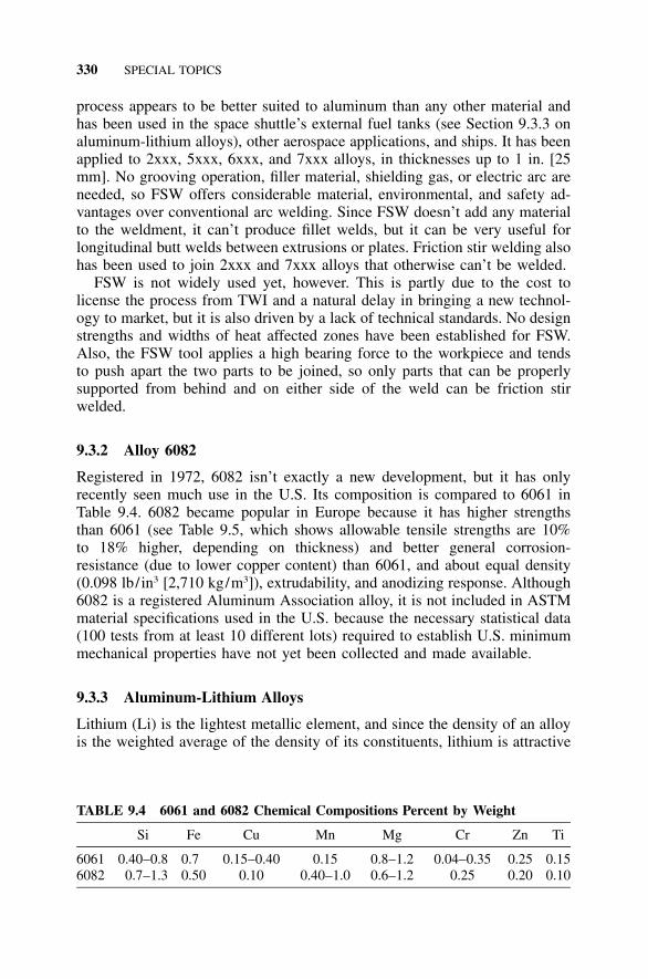
330 SPECIAL TOPICS
TABLE 9.4 6061 and 6082 Chemical Compositions Percent by Weight
Si Fe Cu Mn Mg Cr Zn Ti
6061 0.40–0.8 0.7 0.15–0.40 0.15 0.8–1.2 0.04–0.35 0.25 0.156082 0.7–1.3 0.50 0.10 0.40–1.0 0.6–1.2 0.25 0.20 0.10
process appears to be better suited to aluminum than any other material andhas been used in the space shuttle’s external fuel tanks (see Section 9.3.3 onaluminum-lithium alloys), other aerospace applications, and ships. It has beenapplied to 2xxx, 5xxx, 6xxx, and 7xxx alloys, in thicknesses up to 1 in. [25mm]. No grooving operation, filler material, shielding gas, or electric arc areneeded, so FSW offers considerable material, environmental, and safety ad-vantages over conventional arc welding. Since FSW doesn’t add any materialto the weldment, it can’t produce fillet welds, but it can be very useful forlongitudinal butt welds between extrusions or plates. Friction stir welding alsohas been used to join 2xxx and 7xxx alloys that otherwise can’t be welded.
FSW is not widely used yet, however. This is partly due to the cost tolicense the process from TWI and a natural delay in bringing a new technol-ogy to market, but it is also driven by a lack of technical standards. No designstrengths and widths of heat affected zones have been established for FSW.Also, the FSW tool applies a high bearing force to the workpiece and tendsto push apart the two parts to be joined, so only parts that can be properlysupported from behind and on either side of the weld can be friction stirwelded.
9.3.2 Alloy 6082
Registered in 1972, 6082 isn’t exactly a new development, but it has onlyrecently seen much use in the U.S. Its composition is compared to 6061 inTable 9.4. 6082 became popular in Europe because it has higher strengthsthan 6061 (see Table 9.5, which shows allowable tensile strengths are 10%to 18% higher, depending on thickness) and better general corrosion-resistance (due to lower copper content) than 6061, and about equal density(0.098 lb/in3 [2,710 kg/m3]), extrudability, and anodizing response. Although6082 is a registered Aluminum Association alloy, it is not included in ASTMmaterial specifications used in the U.S. because the necessary statistical data(100 tests from at least 10 different lots) required to establish U.S. minimummechanical properties have not yet been collected and made available.
9.3.3 Aluminum-Lithium Alloys
Lithium (Li) is the lightest metallic element, and since the density of an alloyis the weighted average of the density of its constituents, lithium is attractive
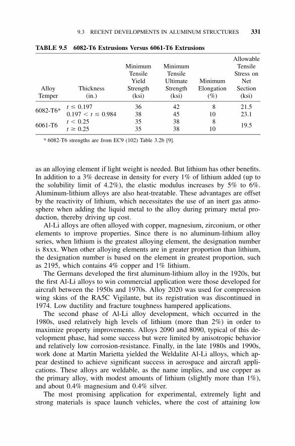
9.3 RECENT DEVELOPMENTS IN ALUMINUM STRUCTURES 331
TABLE 9.5 6082-T6 Extrusions Versus 6061-T6 Extrusions
AlloyTemper
Thickness(in.)
MinimumTensileYield
Strength(ksi)
MinimumTensile
UltimateStrength
(ksi)
MinimumElongation
(%)
AllowableTensile
Stress onNet
Section(ksi)
6082-T6*t � 0.1970.197 � t � 0.984
3638
4245
810
21.523.1
6061-T6t � 0.25t � 0.25
3535
3838
810
19.5
* 6082-T6 strengths are from EC9 (102) Table 3.2b [9].
as an alloying element if light weight is needed. But lithium has other benefits.In addition to a 3% decrease in density for every 1% of lithium added (up tothe solubility limit of 4.2%), the elastic modulus increases by 5% to 6%.Aluminum-lithium alloys are also heat-treatable. These advantages are offsetby the reactivity of lithium, which necessitates the use of an inert gas atmo-sphere when adding the liquid metal to the alloy during primary metal pro-duction, thereby driving up cost.
Al-Li alloys are often alloyed with copper, magnesium, zirconium, or otherelements to improve properties. Since there is no aluminum-lithium alloyseries, when lithium is the greatest alloying element, the designation numberis 8xxx. When other alloying elements are in greater proportion than lithium,the designation number is based on the element in greatest proportion, suchas 2195, which contains 4% copper and 1% lithium.
The Germans developed the first aluminum-lithium alloy in the 1920s, butthe first Al-Li alloys to win commercial application were those developed foraircraft between the 1950s and 1970s. Alloy 2020 was used for compressionwing skins of the RA5C Vigilante, but its registration was discontinued in1974. Low ductility and fracture toughness hampered applications.
The second phase of Al-Li alloy development, which occurred in the1980s, used relatively high levels of lithium (more than 2%) in order tomaximize property improvements. Alloys 2090 and 8090, typical of this de-velopment phase, had some success but were limited by anisotropic behaviorand relatively low corrosion-resistance. Finally, in the late 1980s and 1990s,work done at Martin Marietta yielded the Weldalite Al-Li alloys, which ap-pear destined to achieve significant success in aerospace and aircraft appli-cations. These alloys are weldable, as the name implies, and use copper asthe primary alloy, with modest amounts of lithium (slightly more than 1%),and about 0.4% magnesium and 0.4% silver.
The most promising application for experimental, extremely light andstrong materials is space launch vehicles, where the cost of attaining low
332 SPECIAL TOPICS
earth orbit is about $8,000 per kg and the number of reuses is limited. TheU.S. Space Shuttle external fuel tank is a good example. The first applicationof the Weldalite type alloys was the use of 2195 to replace 2219, a weldablealuminum-copper alloy, for the shuttle’s liquid hydrogen and liquid oxygentanks, producing a weight savings of 3,500 kg. Alloy 2197 is now being usedto refurbish F-16 fighter-jet bulkheads, improving the range and performanceof the aircraft. Commercial aircraft applications are anticipated next. As con-sumption has increased, Al-Li alloy material costs have fallen from a premiumof 20 times that of common alloys to less than 4 times. It’s unlikely, however,that Al-Li alloys will see any significant use outside aerospace applications.
9.3.4 The New Aluminum Automotive Alloys
The need to reduce emissions while enhancing performance and adding fea-tures has driven manufacturers to use more aluminum in automobiles andlight trucks. This effort has been accompanied by the development of newaluminum alloys specifically tailored for these applications. Many of thesealloys are too new to be listed in ASTM specifications or Aluminum Standardsand Data, so detailed information is given here.
Since automobiles and light trucks undergo a paint-bake cycle at temper-atures high enough to affect the temper of both heat-treatable and non-heat-treatable aluminum alloys, the automotive alloys are provided in the -T4(solution-heat-treated) and -O (annealed) tempers, respectively. Both have thebest formability in these tempers for the cold-working they undergo in theprocess of being formed into body panels (6). The forming operation increasesstrengths through cold-working. The subsequent paint bake artificially agesthe heat-treatable alloys, which can additionally increase their strength, butre-anneals the non-heat-treatable alloys, erasing any strength increase due tocold work. High strength is not necessarily important in this application,however.
The automotive alloys fall in three groups:
• 2xxx series (aluminum-copper alloys), including 2008, 2010, and 2036.Alloys 2008 and 2010 were developed to provide improved formabilityover 2036. Alloy 2036 has more copper than 2008 and 2010, giving itabout 40% higher strength but less corrosion resistance. These alloys areheat-treatable.
• 5xxx series (aluminum-magnesium alloys), including 5182 and 5754.5182 was developed for the ends of beverage cans. It has a high mag-nesium content, providing high strength but also sensitivity to corrosionwhen exposed to temperatures above 150�F for extended periods. 5754is a variant on 5454, with slightly more magnesium (3.1% versus 2.7%)and lower strength, but better formability.
• 6xxx series (aluminum-magnesium-silicon alloys), including 6009, 6111,and 6022. These alloys are heat-treatable and can attain fairly high
9.3 RECENT DEVELOPMENTS IN ALUMINUM STRUCTURES 333
strengths during the paint-bake cycle. The newest of these alloys, 6022,is used in the Plymouth Prowler body panels.
Extrusions have not seen significant automotive use, but some alloys, such as7029, have been used in bumpers for some time (3).
9.3.5 Aluminum Metal Matrix Composites
A relatively new product, aluminum metal matrix composites (MMCs) consistof an aluminum alloy matrix with carbon, metallic, or, most commonly, ce-ramic reinforcement. Of all metals, aluminum is the most commonly usedmatrix material in MMCs. MMCs combine the low density of aluminum withthe benefits of ceramics, such as strength, stiffness (by increasing the modulusof elasticity), wear resistance, and high-temperature properties. MMCs can beformed from both solid and molten states into forgings, extrusions, sheet andplate, and castings. Disadvantages include decreased ductility and higher cost;MMCs cost about three times more than conventional aluminum alloys. Yeteven though they’re still being developed, MMCs have been applied in suchautomotive parts as diesel engine pistons, cylinder liners, and drive shafts,and such brake components as rotors.
Reinforcements are characterized as continuous or discontinuous, depend-ing on their shape and make up 10% to 70% of the composite by volume.Continuous fiber or filament reinforcements (designated f) include graphite,silicon carbide (SiC), boron, and aluminum oxide (Al2O3). Discontinuous re-inforcements include SiC whiskers (designated w), SiC, or Al2O3 particles(designated p), or short or chopped (designated c) Al2O3 or graphite fibers.The Aluminum Association standard designation system for aluminum MMCsidentifies each as:
matrix material/reinforcement material/reinforcement volume %, form
For example, 2124/SiC/25w is aluminum alloy 2124 reinforced with 25%by volume of silicon carbide whiskers; 6061/Al2O3/10p is aluminum alloy6061 reinforced with 10% by volume of aluminum oxide particles.

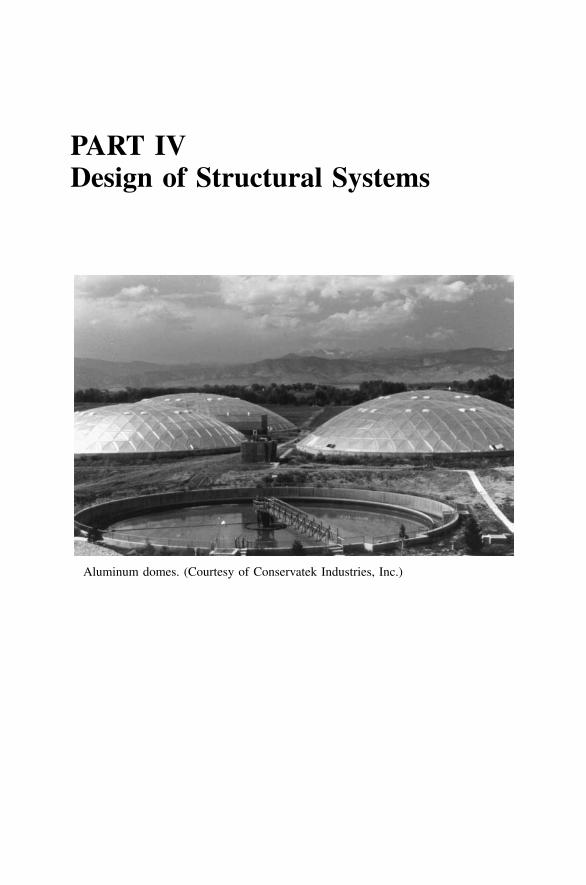
PART IVDesign of Structural Systems
Aluminum domes. (Courtesy of Conservatek Industries, Inc.)

337
10 Structural Systems Builtwith Aluminum
In previous chapters, we discussed the design of various kinds of structuralmembers, for example, columns, welded members, and beams, and failuremodes, such as fracture and fatigue. In this chapter, we’ll demonstrate someof these provisions in the design of aluminum structural systems. Section 10.1deals with cold-formed sections; a latticed dome is presented in Section 10.2to illustrate frame design; structural systems using aluminum with other ma-terials (composite members) are addressed in Section 10.3; and Section 10.4covers pressure piping.
10.1 COLD-FORMED ALUMINUM CONSTRUCTION
Aluminum sheet may be formed by various processes into structural members.We refer to these members as formed-sheet or cold-formed construction, andthey have much in common with cold-formed steel. In fact, many of the issuesin cold-formed metal design have been visited by steel researchers, as wellas aluminum investigators. A popular kind of formed-sheet construction isbuilding sheathing, such as corrugated siding, but sheet can also be used tofabricate structural frame members, such as channels and angles.
10.1.1 Building Sheathing
As we discussed in Section 3.1.5, many pre-formed aluminum products areuseful in construction, especially building sheathing, which includes roofingand siding. Information on dimensions of profiles, load-span tables, and fin-ishes is given in Section 3.1.5. You might have hoped that load-span tableswould solve all your problems, but you knew it wasn’t going to be that easy.Here are some additional considerations.
Thermal Expansion and Contraction The 5th edition of the AluminumSpecifications recommended (in Appendix B, Aluminum Formed-SheetBuilding Sheathing Design Guide) that sheets with lengths in excess of 30 ft[10 m] should not be used unless provision was made to accommodate ex-pansion and contraction. Changes in temperature caused the expansion andcontraction of concern in this recommendation. Exposure to sunlight can pro-
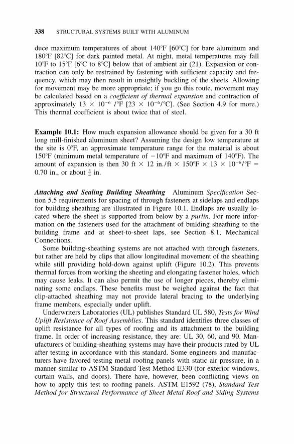
338 STRUCTURAL SYSTEMS BUILT WITH ALUMINUM
duce maximum temperatures of about 140�F [60�C] for bare aluminum and180�F [82�C] for dark painted metal. At night, metal temperatures may fall10�F to 15�F [6�C to 8�C] below that of ambient air (21). Expansion or con-traction can only be restrained by fastening with sufficient capacity and fre-quency, which may then result in unsightly buckling of the sheets. Allowingfor movement may be more appropriate; if you go this route, movement maybe calculated based on a coefficient of thermal expansion and contraction ofapproximately 13 � 10�6 /�F [23 � 10�6 /�C]. (See Section 4.9 for more.)This thermal coefficient is about twice that of steel.
Example 10.1: How much expansion allowance should be given for a 30 ftlong mill-finished aluminum sheet? Assuming the design low temperature atthe site is 0�F, an approximate temperature range for the material is about150�F (minimum metal temperature of �10�F and maximum of 140�F). Theamount of expansion is then 30 ft � 12 in./ft � 150�F � 13 � 10�6 / �F �0.70 in., or about in.3–4
Attaching and Sealing Building Sheathing Aluminum Specification Sec-tion 5.5 requirements for spacing of through fasteners at sidelaps and endlapsfor building sheathing are illustrated in Figure 10.1. Endlaps are usually lo-cated where the sheet is supported from below by a purlin. For more infor-mation on the fasteners used for the attachment of building sheathing to thebuilding frame and at sheet-to-sheet laps, see Section 8.1, MechanicalConnections.
Some building-sheathing systems are not attached with through fasteners,but rather are held by clips that allow longitudinal movement of the sheathingwhile still providing hold-down against uplift (Figure 10.2). This preventsthermal forces from working the sheeting and elongating fastener holes, whichmay cause leaks. It can also permit the use of longer pieces, thereby elimi-nating some endlaps. These benefits must be weighed against the fact thatclip-attached sheathing may not provide lateral bracing to the underlyingframe members, especially under uplift.
Underwriters Laboratories (UL) publishes Standard UL 580, Tests for WindUplift Resistance of Roof Assemblies. This standard identifies three classes ofuplift resistance for all types of roofing and its attachment to the buildingframe. In order of increasing resistance, they are: UL 30, 60, and 90. Man-ufacturers of building-sheathing systems may have their products rated by ULafter testing in accordance with this standard. Some engineers and manufac-turers have favored testing metal roofing panels with static air pressure, in amanner similar to ASTM Standard Test Method E330 (for exterior windows,curtain walls, and doors). There have, however, been conflicting views onhow to apply this test to roofing panels. ASTM E1592 (78), Standard TestMethod for Structural Performance of Sheet Metal Roof and Siding Systems
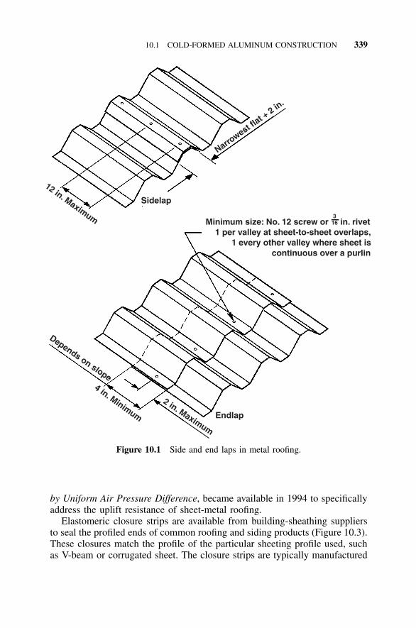
10.1 COLD-FORMED ALUMINUM CONSTRUCTION 339
Narrowest fl
at + 2 in
.
Sidelap
12 in. Maximum Minimum size: No. 12 screw or in. rivet 1 per valley at sheet-to-sheet overlaps, 1 every other valley where sheet is continuous over a purlin
316
Endlap
2 in. Maximum
Depends on slope4 in. Minimum
Figure 10.1 Side and end laps in metal roofing.
by Uniform Air Pressure Difference, became available in 1994 to specificallyaddress the uplift resistance of sheet-metal roofing.
Elastomeric closure strips are available from building-sheathing suppliersto seal the profiled ends of common roofing and siding products (Figure 10.3).These closures match the profile of the particular sheeting profile used, suchas V-beam or corrugated sheet. The closure strips are typically manufactured
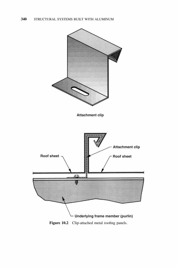
340 STRUCTURAL SYSTEMS BUILT WITH ALUMINUM
Attachment clip
Roof sheet
Attachment clip
Roof sheet
Underlying frame member (purlin)
Figure 10.2 Clip-attached metal roofing panels.
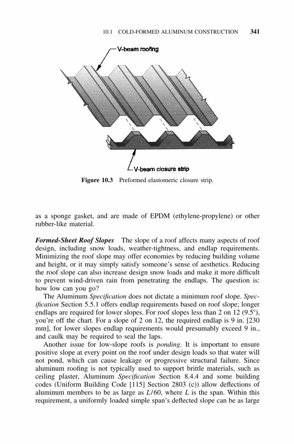
10.1 COLD-FORMED ALUMINUM CONSTRUCTION 341
Figure 10.3 Preformed elastomeric closure strip.
as a sponge gasket, and are made of EPDM (ethylene-propylene) or otherrubber-like material.
Formed-Sheet Roof Slopes The slope of a roof affects many aspects of roofdesign, including snow loads, weather-tightness, and endlap requirements.Minimizing the roof slope may offer economies by reducing building volumeand height, or it may simply satisfy someone’s sense of aesthetics. Reducingthe roof slope can also increase design snow loads and make it more difficultto prevent wind-driven rain from penetrating the endlaps. The question is:how low can you go?
The Aluminum Specification does not dictate a minimum roof slope. Spec-ification Section 5.5.1 offers endlap requirements based on roof slope; longerendlaps are required for lower slopes. For roof slopes less than 2 on 12 (9.5�),you’re off the chart. For a slope of 2 on 12, the required endlap is 9 in. [230mm], for lower slopes endlap requirements would presumably exceed 9 in.,and caulk may be required to seal the laps.
Another issue for low-slope roofs is ponding. It is important to ensurepositive slope at every point on the roof under design loads so that water willnot pond, which can cause leakage or progressive structural failure. Sincealuminum roofing is not typically used to support brittle materials, such asceiling plaster, Aluminum Specification Section 8.4.4 and some buildingcodes (Uniform Building Code [115] Section 2803 (c)) allow deflections ofaluminum members to be as large as L /60, where L is the span. Within thisrequirement, a uniformly loaded simple span’s deflected slope can be as large
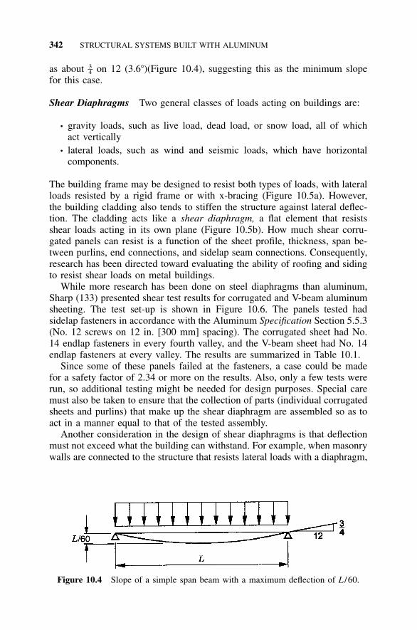
342 STRUCTURAL SYSTEMS BUILT WITH ALUMINUM
Figure 10.4 Slope of a simple span beam with a maximum deflection of L /60.
as about on 12 (3.6�)(Figure 10.4), suggesting this as the minimum slope3–4for this case.
Shear Diaphragms Two general classes of loads acting on buildings are:
• gravity loads, such as live load, dead load, or snow load, all of whichact vertically
• lateral loads, such as wind and seismic loads, which have horizontalcomponents.
The building frame may be designed to resist both types of loads, with lateralloads resisted by a rigid frame or with x-bracing (Figure 10.5a). However,the building cladding also tends to stiffen the structure against lateral deflec-tion. The cladding acts like a shear diaphragm, a flat element that resistsshear loads acting in its own plane (Figure 10.5b). How much shear corru-gated panels can resist is a function of the sheet profile, thickness, span be-tween purlins, end connections, and sidelap seam connections. Consequently,research has been directed toward evaluating the ability of roofing and sidingto resist shear loads on metal buildings.
While more research has been done on steel diaphragms than aluminum,Sharp (133) presented shear test results for corrugated and V-beam aluminumsheeting. The test set-up is shown in Figure 10.6. The panels tested hadsidelap fasteners in accordance with the Aluminum Specification Section 5.5.3(No. 12 screws on 12 in. [300 mm] spacing). The corrugated sheet had No.14 endlap fasteners in every fourth valley, and the V-beam sheet had No. 14endlap fasteners at every valley. The results are summarized in Table 10.1.
Since some of these panels failed at the fasteners, a case could be madefor a safety factor of 2.34 or more on the results. Also, only a few tests wererun, so additional testing might be needed for design purposes. Special caremust also be taken to ensure that the collection of parts (individual corrugatedsheets and purlins) that make up the shear diaphragm are assembled so as toact in a manner equal to that of the tested assembly.
Another consideration in the design of shear diaphragms is that deflectionmust not exceed what the building can withstand. For example, when masonrywalls are connected to the structure that resists lateral loads with a diaphragm,
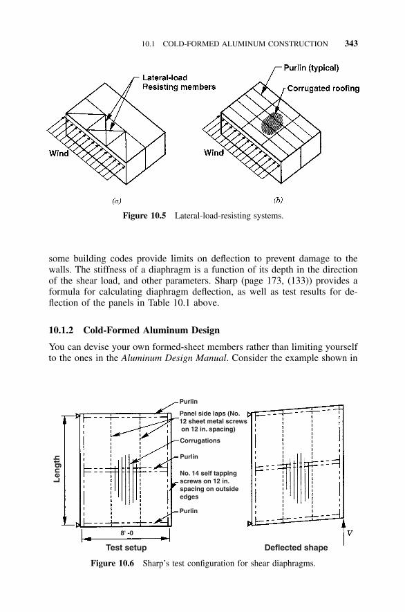
10.1 COLD-FORMED ALUMINUM CONSTRUCTION 343
Figure 10.5 Lateral-load-resisting systems.
Purlin
Panel side laps (No. 12 sheet metal screws on 12 in. spacing)
Corrugations
Purlin
No. 14 self tapping screws on 12 in. spacing on outsideedges
Purlin
8' -0
Test setup
Len
gth
Deflected shape
Figure 10.6 Sharp’s test configuration for shear diaphragms.
some building codes provide limits on deflection to prevent damage to thewalls. The stiffness of a diaphragm is a function of its depth in the directionof the shear load, and other parameters. Sharp (page 173, (133)) provides aformula for calculating diaphragm deflection, as well as test results for de-flection of the panels in Table 10.1 above.
10.1.2 Cold-Formed Aluminum Design
You can devise your own formed-sheet members rather than limiting yourselfto the ones in the Aluminum Design Manual. Consider the example shown in
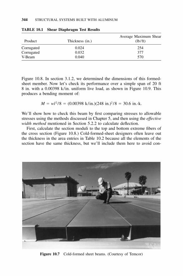
344 STRUCTURAL SYSTEMS BUILT WITH ALUMINUM
TABLE 10.1 Shear Diaphragm Test Results
Product Thickness (in.)Average Maximum Shear
(lb / ft)
Corrugated 0.024 254Corrugated 0.032 377V-Beam 0.040 570
Figure 10.7 Cold-formed sheet beams. (Courtesy of Temcor)
Figure 10.8. In section 3.1.2, we determined the dimensions of this formed-sheet member. Now let’s check its performance over a simple span of 20 ft8 in. with a 0.00398 k/in. uniform live load, as shown in Figure 10.9. Thisproduces a bending moment of:
2 2M � wl /8 � (0.00398 k/in.)(248 in.) /8 � 30.6 in.-k.
We’ll show how to check this beam by first comparing stresses to allowablestresses using the methods discussed in Chapter 5, and then using the effectivewidth method mentioned in Section 5.2.2 to calculate deflection.
First, calculate the section moduli to the top and bottom extreme fibers ofthe cross section (Figure 10.8.) Cold-formed-sheet designers often leave outthe thickness in the area entries in Table 10.2 because all the elements of thesection have the same thickness, but we’ll include them here to avoid con-
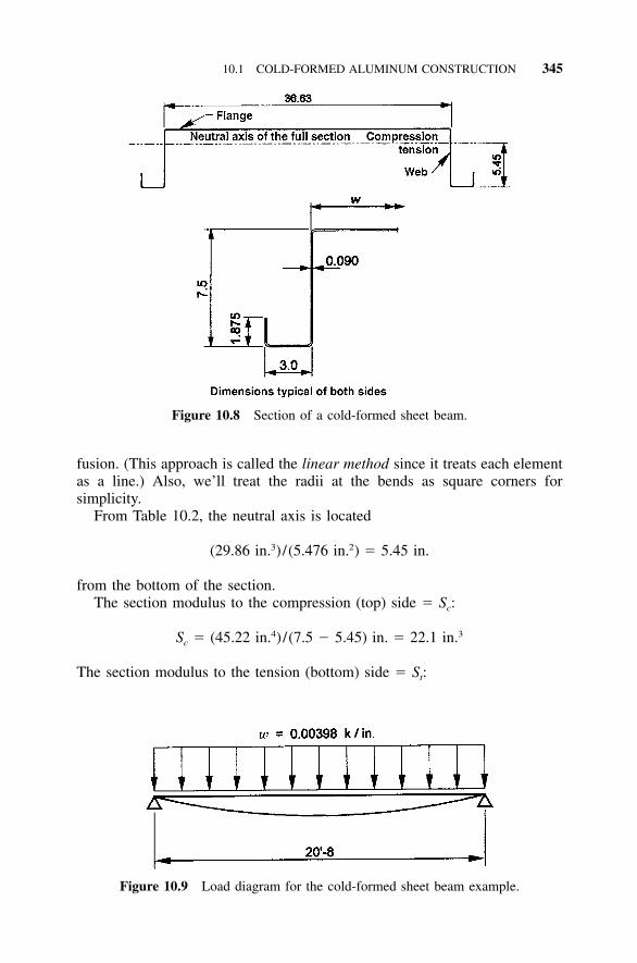
10.1 COLD-FORMED ALUMINUM CONSTRUCTION 345
Figure 10.8 Section of a cold-formed sheet beam.
Figure 10.9 Load diagram for the cold-formed sheet beam example.
fusion. (This approach is called the linear method since it treats each elementas a line.) Also, we’ll treat the radii at the bends as square corners forsimplicity.
From Table 10.2, the neutral axis is located
3 2(29.86 in. ) /(5.476 in. ) � 5.45 in.
from the bottom of the section.The section modulus to the compression (top) side � Sc:
4 3S � (45.22 in. ) /(7.5 � 5.45) in. � 22.1 in.c
The section modulus to the tension (bottom) side � St:
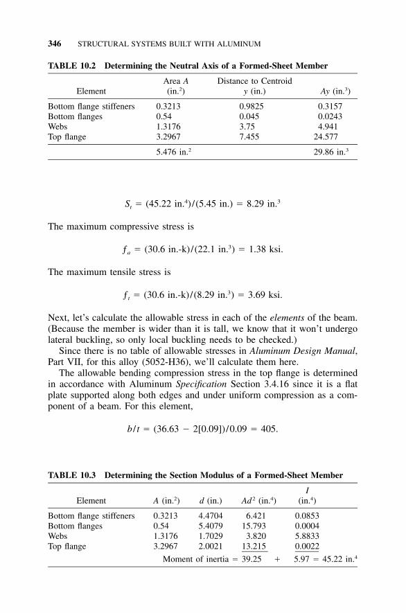
346 STRUCTURAL SYSTEMS BUILT WITH ALUMINUM
TABLE 10.2 Determining the Neutral Axis of a Formed-Sheet Member
ElementArea A(in.2)
Distance to Centroidy (in.) Ay (in.3)
Bottom flange stiffeners 0.3213 0.9825 0.3157Bottom flanges 0.54 0.045 0.0243Webs 1.3176 3.75 4.941Top flange 3.2967 7.455 24.577
5.476 in.2 29.86 in.3
TABLE 10.3 Determining the Section Modulus of a Formed-Sheet Member
Element A (in.2) d (in.) Ad 2 (in.4)I
(in.4)
Bottom flange stiffeners 0.3213 4.4704 6.421 0.0853Bottom flanges 0.54 5.4079 15.793 0.0004Webs 1.3176 1.7029 3.820 5.8833Top flange 3.2967 2.0021 13.215 0.0022
Moment of inertia � 39.25 � 5.97 � 45.22 in.4
4 3S � (45.22 in. ) /(5.45 in.) � 8.29 in.t
The maximum compressive stress is
3ƒ � (30.6 in.-k)/(22.1 in. ) � 1.38 ksi.a
The maximum tensile stress is
3ƒ � (30.6 in.-k)/(8.29 in. ) � 3.69 ksi.t
Next, let’s calculate the allowable stress in each of the elements of the beam.(Because the member is wider than it is tall, we know that it won’t undergolateral buckling, so only local buckling needs to be checked.)
Since there is no table of allowable stresses in Aluminum Design Manual,Part VII, for this alloy (5052-H36), we’ll calculate them here.
The allowable bending compression stress in the top flange is determinedin accordance with Aluminum Specification Section 3.4.16 since it is a flatplate supported along both edges and under uniform compression as a com-ponent of a beam. For this element,
b / t � (36.63 � 2[0.09])/0.09 � 405.
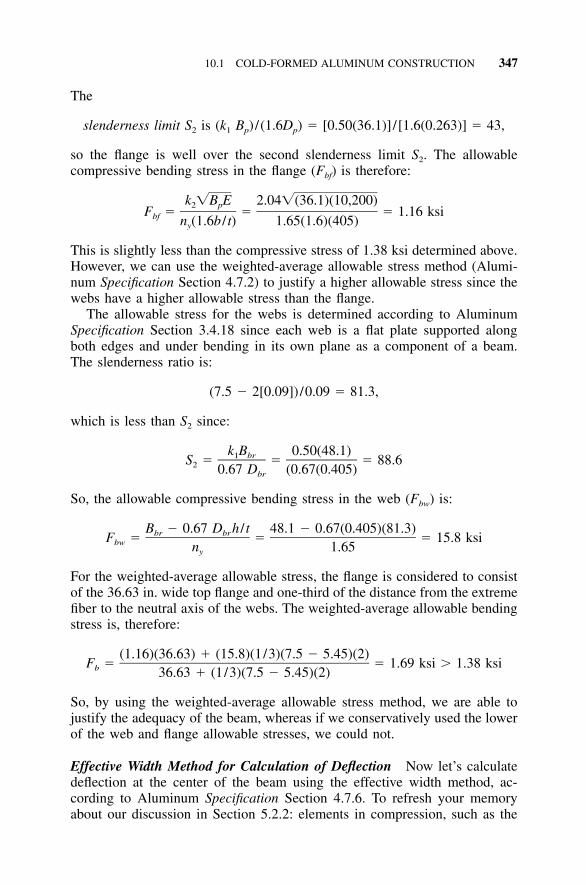
10.1 COLD-FORMED ALUMINUM CONSTRUCTION 347
The
slenderness limit S is (k B ) /(1.6D ) � [0.50(36.1)]/[1.6(0.263)] � 43,2 1 p p
so the flange is well over the second slenderness limit S2. The allowablecompressive bending stress in the flange (Fbf) is therefore:
k �B E 2.04�(36.1)(10,200)2 pF � � � 1.16 ksibf n (1.6b / t) 1.65(1.6)(405)y
This is slightly less than the compressive stress of 1.38 ksi determined above.However, we can use the weighted-average allowable stress method (Alumi-num Specification Section 4.7.2) to justify a higher allowable stress since thewebs have a higher allowable stress than the flange.
The allowable stress for the webs is determined according to AluminumSpecification Section 3.4.18 since each web is a flat plate supported alongboth edges and under bending in its own plane as a component of a beam.The slenderness ratio is:
(7.5 � 2[0.09])/0.09 � 81.3,
which is less than S2 since:
k B 0.50(48.1)1 brS � � � 88.62 0.67 D (0.67(0.405)br
So, the allowable compressive bending stress in the web (Fbw) is:
B � 0.67 D h / t 48.1 � 0.67(0.405)(81.3)br brF � � � 15.8 ksibw n 1.65y
For the weighted-average allowable stress, the flange is considered to consistof the 36.63 in. wide top flange and one-third of the distance from the extremefiber to the neutral axis of the webs. The weighted-average allowable bendingstress is, therefore:
(1.16)(36.63) � (15.8)(1/3)(7.5 � 5.45)(2)F � � 1.69 ksi � 1.38 ksib 36.63 � (1/3)(7.5 � 5.45)(2)
So, by using the weighted-average allowable stress method, we are able tojustify the adequacy of the beam, whereas if we conservatively used the lowerof the web and flange allowable stresses, we could not.
Effective Width Method for Calculation of Deflection Now let’s calculatedeflection at the center of the beam using the effective width method, ac-cording to Aluminum Specification Section 4.7.6. To refresh your memoryabout our discussion in Section 5.2.2: elements in compression, such as the
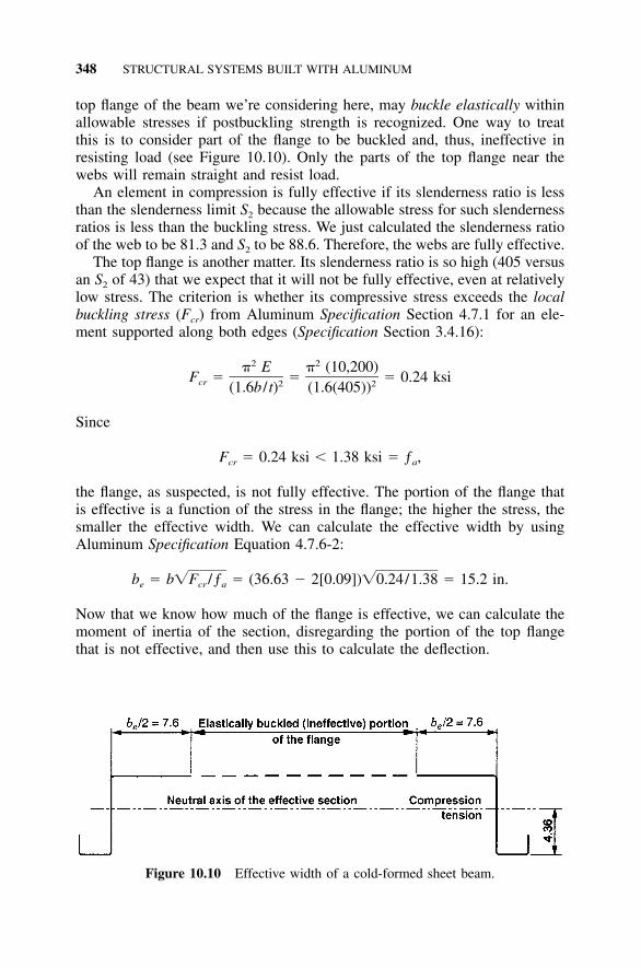
348 STRUCTURAL SYSTEMS BUILT WITH ALUMINUM
Figure 10.10 Effective width of a cold-formed sheet beam.
top flange of the beam we’re considering here, may buckle elastically withinallowable stresses if postbuckling strength is recognized. One way to treatthis is to consider part of the flange to be buckled and, thus, ineffective inresisting load (see Figure 10.10). Only the parts of the top flange near thewebs will remain straight and resist load.
An element in compression is fully effective if its slenderness ratio is lessthan the slenderness limit S2 because the allowable stress for such slendernessratios is less than the buckling stress. We just calculated the slenderness ratioof the web to be 81.3 and S2 to be 88.6. Therefore, the webs are fully effective.
The top flange is another matter. Its slenderness ratio is so high (405 versusan S2 of 43) that we expect that it will not be fully effective, even at relativelylow stress. The criterion is whether its compressive stress exceeds the localbuckling stress (Fcr) from Aluminum Specification Section 4.7.1 for an ele-ment supported along both edges (Specification Section 3.4.16):
2 2� E � (10,200)F � � � 0.24 ksicr 2 2(1.6b / t) (1.6(405))
Since
F � 0.24 ksi � 1.38 ksi � ƒ ,cr a
the flange, as suspected, is not fully effective. The portion of the flange thatis effective is a function of the stress in the flange; the higher the stress, thesmaller the effective width. We can calculate the effective width by usingAluminum Specification Equation 4.7.6-2:
b � b�F /ƒ � (36.63 � 2[0.09])�0.24/1.38 � 15.2 in.e cr a
Now that we know how much of the flange is effective, we can calculate themoment of inertia of the section, disregarding the portion of the top flangethat is not effective, and then use this to calculate the deflection.
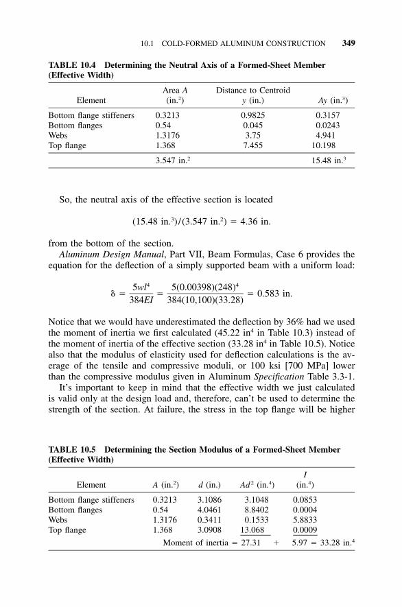
10.1 COLD-FORMED ALUMINUM CONSTRUCTION 349
TABLE 10.4 Determining the Neutral Axis of a Formed-Sheet Member(Effective Width)
ElementArea A(in.2)
Distance to Centroidy (in.) Ay (in.3)
Bottom flange stiffeners 0.3213 0.9825 0.3157Bottom flanges 0.54 0.045 0.0243Webs 1.3176 3.75 4.941Top flange 1.368 7.455 10.198
3.547 in.2 15.48 in.3
TABLE 10.5 Determining the Section Modulus of a Formed-Sheet Member(Effective Width)
Element A (in.2) d (in.) Ad 2 (in.4)I
(in.4)
Bottom flange stiffeners 0.3213 3.1086 3.1048 0.0853Bottom flanges 0.54 4.0461 8.8402 0.0004Webs 1.3176 0.3411 0.1533 5.8833Top flange 1.368 3.0908 13.068 0.0009
Moment of inertia � 27.31 � 5.97 � 33.28 in.4
So, the neutral axis of the effective section is located
3 2(15.48 in. ) /(3.547 in. ) � 4.36 in.
from the bottom of the section.Aluminum Design Manual, Part VII, Beam Formulas, Case 6 provides the
equation for the deflection of a simply supported beam with a uniform load:
4 45wl 5(0.00398)(248)� � � � 0.583 in.
384EI 384(10,100)(33.28)
Notice that we would have underestimated the deflection by 36% had we usedthe moment of inertia we first calculated (45.22 in4 in Table 10.3) instead ofthe moment of inertia of the effective section (33.28 in4 in Table 10.5). Noticealso that the modulus of elasticity used for deflection calculations is the av-erage of the tensile and compressive moduli, or 100 ksi [700 MPa] lowerthan the compressive modulus given in Aluminum Specification Table 3.3-1.
It’s important to keep in mind that the effective width we just calculatedis valid only at the design load and, therefore, can’t be used to determine thestrength of the section. At failure, the stress in the top flange will be higher
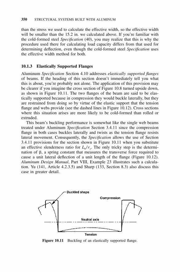
350 STRUCTURAL SYSTEMS BUILT WITH ALUMINUM
Figure 10.11 Buckling of an elastically supported flange.
than the stress we used to calculate the effective width, so the effective widthwill be smaller than the 15.2 in. we calculated above. If you’re familiar withthe cold-formed steel Specification (40), you may realize that this is why theprocedure used there for calculating load capacity differs from that used fordetermining deflection, even though the cold-formed steel Specification usesthe effective width method for both.
10.1.3 Elastically Supported Flanges
Aluminum Specification Section 4.10 addresses elastically supported flangesof beams. If the heading of this section doesn’t immediately tell you whatthis is about, you’re probably not alone. The application of this provision maybe clearer if you imagine the cross section of Figure 10.8 turned upside down,as shown in Figure 10.11. The two flanges of the beam are said to be elas-tically supported because in compression they would buckle laterally, but theyare restrained from doing so by virtue of the elastic support that the tensionflange and webs provide (see the dashed lines in Figure 10.12). Cross sectionswhere this situation arises are more likely to be cold-formed than rolled orextruded.
This beam’s buckling performance is somewhat like the single web beamstreated under Aluminum Specification Section 3.4.11 since the compressionflange in both cases buckles laterally and twists as the tension flange resistslateral movement. Consequently, the Specification allows the use of Section3.4.11 provisions for the section shown in Figure 10.11 when you substitutean effective slenderness ratio for Lb /ry. The only tricky step is the determi-nation of �, a spring constant that measures the transverse force required tocause a unit lateral deflection of a unit length of the flange (Figure 10.12).Aluminum Design Manual, Part VIII, Example 23 illustrates such a calcula-tion. Yu (141, Article 4.2.3.5) and Sharp (133, Section 8.3) also discuss thiscase in greater detail.
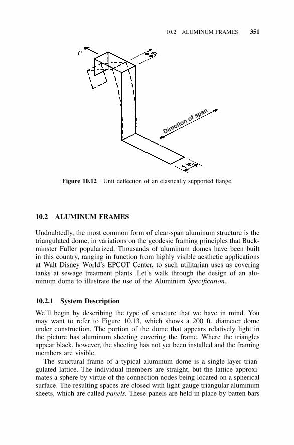
10.2 ALUMINUM FRAMES 351
Direction of span
Figure 10.12 Unit deflection of an elastically supported flange.
10.2 ALUMINUM FRAMES
Undoubtedly, the most common form of clear-span aluminum structure is thetriangulated dome, in variations on the geodesic framing principles that Buck-minster Fuller popularized. Thousands of aluminum domes have been builtin this country, ranging in function from highly visible aesthetic applicationsat Walt Disney World’s EPCOT Center, to such utilitarian uses as coveringtanks at sewage treatment plants. Let’s walk through the design of an alu-minum dome to illustrate the use of the Aluminum Specification.
10.2.1 System Description
We’ll begin by describing the type of structure that we have in mind. Youmay want to refer to Figure 10.13, which shows a 200 ft. diameter domeunder construction. The portion of the dome that appears relatively light inthe picture has aluminum sheeting covering the frame. Where the trianglesappear black, however, the sheeting has not yet been installed and the framingmembers are visible.
The structural frame of a typical aluminum dome is a single-layer trian-gulated lattice. The individual members are straight, but the lattice approxi-mates a sphere by virtue of the connection nodes being located on a sphericalsurface. The resulting spaces are closed with light-gauge triangular aluminumsheets, which are called panels. These panels are held in place by batten bars
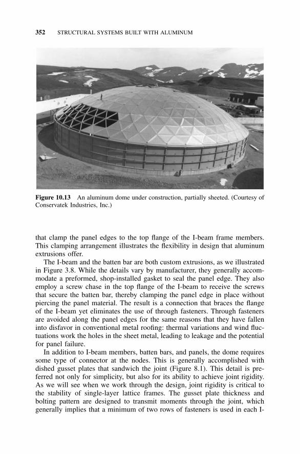
352 STRUCTURAL SYSTEMS BUILT WITH ALUMINUM
Figure 10.13 An aluminum dome under construction, partially sheeted. (Courtesy ofConservatek Industries, Inc.)
that clamp the panel edges to the top flange of the I-beam frame members.This clamping arrangement illustrates the flexibility in design that aluminumextrusions offer.
The I-beam and the batten bar are both custom extrusions, as we illustratedin Figure 3.8. While the details vary by manufacturer, they generally accom-modate a preformed, shop-installed gasket to seal the panel edge. They alsoemploy a screw chase in the top flange of the I-beam to receive the screwsthat secure the batten bar, thereby clamping the panel edge in place withoutpiercing the panel material. The result is a connection that braces the flangeof the I-beam yet eliminates the use of through fasteners. Through fastenersare avoided along the panel edges for the same reasons that they have falleninto disfavor in conventional metal roofing: thermal variations and wind fluc-tuations work the holes in the sheet metal, leading to leakage and the potentialfor panel failure.
In addition to I-beam members, batten bars, and panels, the dome requiressome type of connector at the nodes. This is generally accomplished withdished gusset plates that sandwich the joint (Figure 8.1). This detail is pre-ferred not only for simplicity, but also for its ability to achieve joint rigidity.As we will see when we work through the design, joint rigidity is critical tothe stability of single-layer lattice frames. The gusset plate thickness andbolting pattern are designed to transmit moments through the joint, whichgenerally implies that a minimum of two rows of fasteners is used in each I-
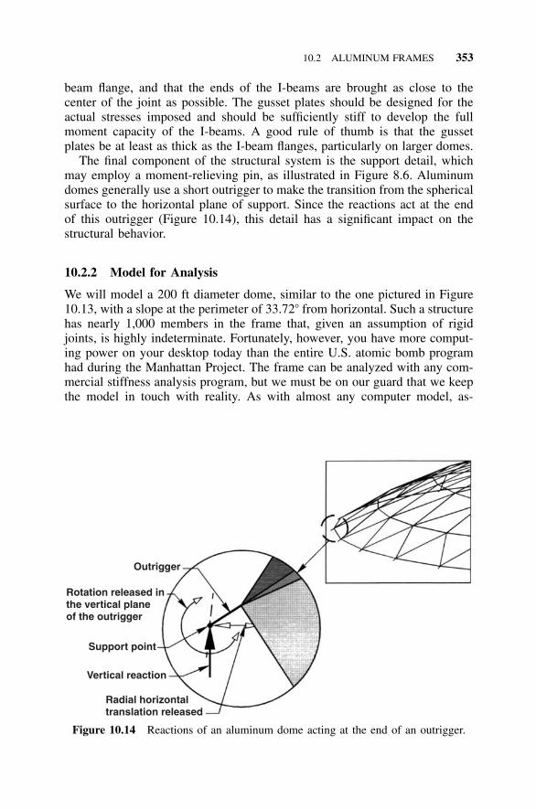
10.2 ALUMINUM FRAMES 353
Outrigger
Rotation released in the vertical planeof the outrigger
Support point
Vertical reaction
Radial horizontaltranslation released
Figure 10.14 Reactions of an aluminum dome acting at the end of an outrigger.
beam flange, and that the ends of the I-beams are brought as close to thecenter of the joint as possible. The gusset plates should be designed for theactual stresses imposed and should be sufficiently stiff to develop the fullmoment capacity of the I-beams. A good rule of thumb is that the gussetplates be at least as thick as the I-beam flanges, particularly on larger domes.
The final component of the structural system is the support detail, whichmay employ a moment-relieving pin, as illustrated in Figure 8.6. Aluminumdomes generally use a short outrigger to make the transition from the sphericalsurface to the horizontal plane of support. Since the reactions act at the endof this outrigger (Figure 10.14), this detail has a significant impact on thestructural behavior.
10.2.2 Model for Analysis
We will model a 200 ft diameter dome, similar to the one pictured in Figure10.13, with a slope at the perimeter of 33.72� from horizontal. Such a structurehas nearly 1,000 members in the frame that, given an assumption of rigidjoints, is highly indeterminate. Fortunately, however, you have more comput-ing power on your desktop today than the entire U.S. atomic bomb programhad during the Manhattan Project. The frame can be analyzed with any com-mercial stiffness analysis program, but we must be on our guard that we keepthe model in touch with reality. As with almost any computer model, as-
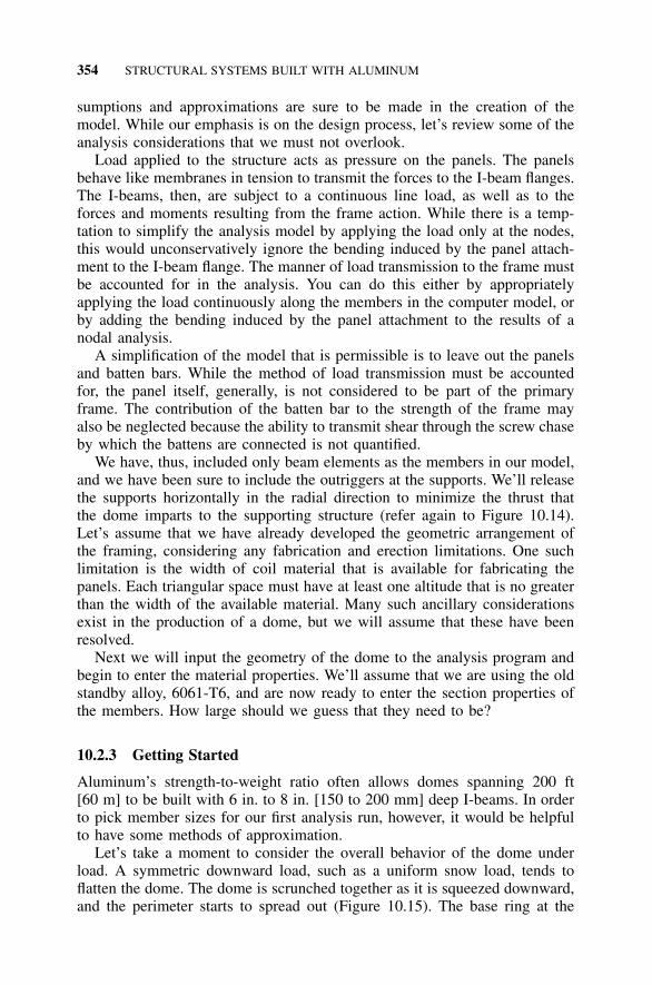
354 STRUCTURAL SYSTEMS BUILT WITH ALUMINUM
sumptions and approximations are sure to be made in the creation of themodel. While our emphasis is on the design process, let’s review some of theanalysis considerations that we must not overlook.
Load applied to the structure acts as pressure on the panels. The panelsbehave like membranes in tension to transmit the forces to the I-beam flanges.The I-beams, then, are subject to a continuous line load, as well as to theforces and moments resulting from the frame action. While there is a temp-tation to simplify the analysis model by applying the load only at the nodes,this would unconservatively ignore the bending induced by the panel attach-ment to the I-beam flange. The manner of load transmission to the frame mustbe accounted for in the analysis. You can do this either by appropriatelyapplying the load continuously along the members in the computer model, orby adding the bending induced by the panel attachment to the results of anodal analysis.
A simplification of the model that is permissible is to leave out the panelsand batten bars. While the method of load transmission must be accountedfor, the panel itself, generally, is not considered to be part of the primaryframe. The contribution of the batten bar to the strength of the frame mayalso be neglected because the ability to transmit shear through the screw chaseby which the battens are connected is not quantified.
We have, thus, included only beam elements as the members in our model,and we have been sure to include the outriggers at the supports. We’ll releasethe supports horizontally in the radial direction to minimize the thrust thatthe dome imparts to the supporting structure (refer again to Figure 10.14).Let’s assume that we have already developed the geometric arrangement ofthe framing, considering any fabrication and erection limitations. One suchlimitation is the width of coil material that is available for fabricating thepanels. Each triangular space must have at least one altitude that is no greaterthan the width of the available material. Many such ancillary considerationsexist in the production of a dome, but we will assume that these have beenresolved.
Next we will input the geometry of the dome to the analysis program andbegin to enter the material properties. We’ll assume that we are using the oldstandby alloy, 6061-T6, and are now ready to enter the section properties ofthe members. How large should we guess that they need to be?
10.2.3 Getting Started
Aluminum’s strength-to-weight ratio often allows domes spanning 200 ft[60 m] to be built with 6 in. to 8 in. [150 to 200 mm] deep I-beams. In orderto pick member sizes for our first analysis run, however, it would be helpfulto have some methods of approximation.
Let’s take a moment to consider the overall behavior of the dome underload. A symmetric downward load, such as a uniform snow load, tends toflatten the dome. The dome is scrunched together as it is squeezed downward,and the perimeter starts to spread out (Figure 10.15). The base ring at the
10.2 ALUMINUM FRAMES 355
Figure 10.15 Behavior of a clear-span dome under uniform downward load.
perimeter of the dome acts as a big hoop in tension to keep the dome fromflattening out. If we momentarily consider the joints to be pinned, we canderive an expression for the force in the base ring.
For a symmetrical load on a dome with evenly spaced supports, the verticalreaction (V) at each support is approximately:
V � P /n (10.1)s
where:
V � vertical reaction at a supportP � total vertical load applied to the domens � number of supports.
If we apply this vertical force to the nodes of the base ring, it must be carriedby those members that are not in a horizontal plane (see Figure 10.16). Sincethese members lie in the slope of the dome at its perimeter, which we set at33.72�, equilibrium requires that they also have a horizontal component offorce. This horizontal component R is equal to:
R � V / tan � (10.2)
where:
R � radial horizontal force at a base-ring node� � angle to horizontal of the dome at its base-ring node
Combining these two equations we have:
R � P / (n tan �) (10.3)s
Now let’s resolve these forces in the horizontal plane (Figure 10.17). The
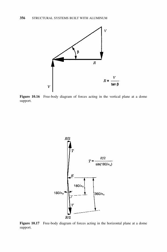
356 STRUCTURAL SYSTEMS BUILT WITH ALUMINUM
Figure 10.16 Free-body diagram of forces acting in the vertical plane at a domesupport.
Figure 10.17 Free-body diagram of forces acting in the horizontal plane at a domesupport.
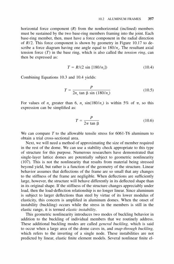
10.2 ALUMINUM FRAMES 357
horizontal force component (R) from the nonhorizontal (inclined) membersmust be sustained by the two base-ring members framing into the joint. Eachbase-ring member, then, must have a force component in the radial directionof R /2. This force component is shown by geometry in Figure 10.17 to de-scribe a force diagram having one angle equal to 180/ns. The resultant axialtension force (T) in the base ring, which is also called the tension ring, canthen be expressed as:
T � R / (2 sin [180/n ]) (10.4)s
Combining Equations 10.3 and 10.4 yields:
PT � (10.5)
2n tan � sin (180/n )s s
For values of ns greater than 6, ns sin(180/ns) is within 5% of �, so thisexpression can be simplified as:
PT � (10.6)
2� tan �
We can compare T to the allowable tensile stress for 6061-T6 aluminum toobtain a trial cross-sectional area.
Next, we will need a method of approximating the size of member requiredin the rest of the dome. We can use a stability check appropriate to this typeof structure for this purpose. Numerous researchers have demonstrated thatsingle-layer lattice domes are potentially subject to geometric nonlinearity(107). This is not the nonlinearity that results from material being stressedbeyond yield, but rather is a function of the geometry of the structure. Linearbehavior assumes that deflections of the frame are so small that any changesto the stiffness of the frame are negligible. When deflections are sufficientlylarge, however, the structure will behave differently in its deflected shape thanin its original shape. If the stiffness of the structure changes appreciably underload, then the load-deflection relationship is no longer linear. Since aluminumis subject to larger deflections than steel by virtue of its lower modulus ofelasticity, this concern is amplified in aluminum domes. When the onset ofinstability (buckling) occurs while the stress in the members is still in theelastic range, it is termed elastic instability.
This geometric nonlinearity introduces two modes of buckling behavior inaddition to the buckling of individual members that we routinely address.These additional buckling modes are called general buckling, which is saidto occur when a large area of the dome caves in, and snap-through buckling,which refers to the inverting of a single node. These instabilities are notpredicted by linear, elastic finite element models. Several nonlinear finite el-
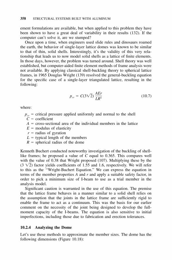
358 STRUCTURAL SYSTEMS BUILT WITH ALUMINUM
ement formulations are available, but when applied to this problem they havebeen shown to have a great deal of variability in their results (132). If thecomputer can’t solve it, are we stumped?
Once upon a time, when engineers used slide rules and dinosaurs roamedthe earth, the behavior of single-layer lattice domes was known to be similarto that of thin, solid shells. Interestingly, it’s the validity of this very rela-tionship that leads us to now model solid shells as a lattice of finite elements.In those days, however, the problem was turned around. Shell theory was wellestablished, but computer-aided finite element methods of frame analysis werenot available. By applying classical shell-buckling theory to spherical latticeframes, in 1965 Douglas Wright (139) resolved the general-buckling equationfor the specific case of a single-layer triangulated lattice, resulting in thefollowing:
AErp � C(3�2) (10.7)cr 2LR
where:
pcr � critical pressure applied uniformly and normal to the shellC � coefficientA � cross-sectional area of the individual members in the latticeE � modulus of elasticityr � radius of gyrationL � typical length of the membersR � spherical radius of the dome
Kenneth Buchert conducted noteworthy investigation of the buckling of shell-like frames; he proposed a value of C equal to 0.365. This compares wellwith the value of 0.38 that Wright proposed (107). Multiplying these by the(3 factor yields coefficients of 1.55 and 1.6, respectively. We will refer�2)to this as the ‘‘Wright-Buchert Equation.’’ We can express the equation interms of the member properties A and r and apply a suitable safety factor, inorder to pick a minimum size of I-beam to use as a trial member in theanalysis model.
Significant caution is warranted in the use of this equation. The premisethat the lattice frame behaves in a manner similar to a solid shell relies onthe assumption that the joints in the lattice frame are sufficiently rigid toenable the frame to act as a continuum. This was the basis for our earliercomment on the necessity of the joint being designed to develop the full-moment capacity of the I-beams. The equation is also sensitive to initialimperfections, including those due to fabrication and erection tolerances.
10.2.4 Analyzing the Dome
Let’s use these methods to approximate the member sizes. The dome has thefollowing dimensions (Figure 10.18):
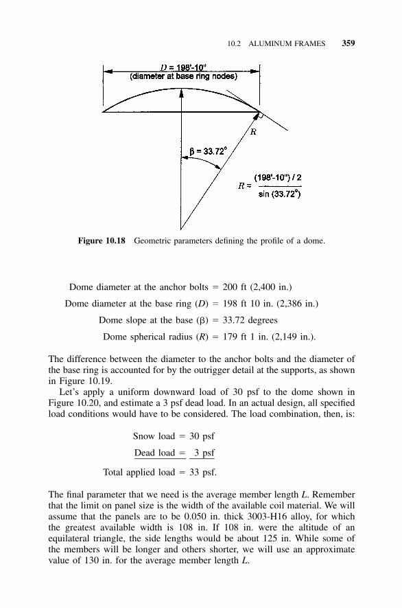
10.2 ALUMINUM FRAMES 359
Figure 10.18 Geometric parameters defining the profile of a dome.
Dome diameter at the anchor bolts � 200 ft (2,400 in.)
Dome diameter at the base ring (D) � 198 ft 10 in. (2,386 in.)
Dome slope at the base (�) � 33.72 degrees
Dome spherical radius (R) � 179 ft 1 in. (2,149 in.).
The difference between the diameter to the anchor bolts and the diameter ofthe base ring is accounted for by the outrigger detail at the supports, as shownin Figure 10.19.
Let’s apply a uniform downward load of 30 psf to the dome shown inFigure 10.20, and estimate a 3 psf dead load. In an actual design, all specifiedload conditions would have to be considered. The load combination, then, is:
Snow load � 30 psf
Dead load � 3 psf
Total applied load � 33 psf.
The final parameter that we need is the average member length L. Rememberthat the limit on panel size is the width of the available coil material. We willassume that the panels are to be 0.050 in. thick 3003-H16 alloy, for whichthe greatest available width is 108 in. If 108 in. were the altitude of anequilateral triangle, the side lengths would be about 125 in. While some ofthe members will be longer and others shorter, we will use an approximatevalue of 130 in. for the average member length L.
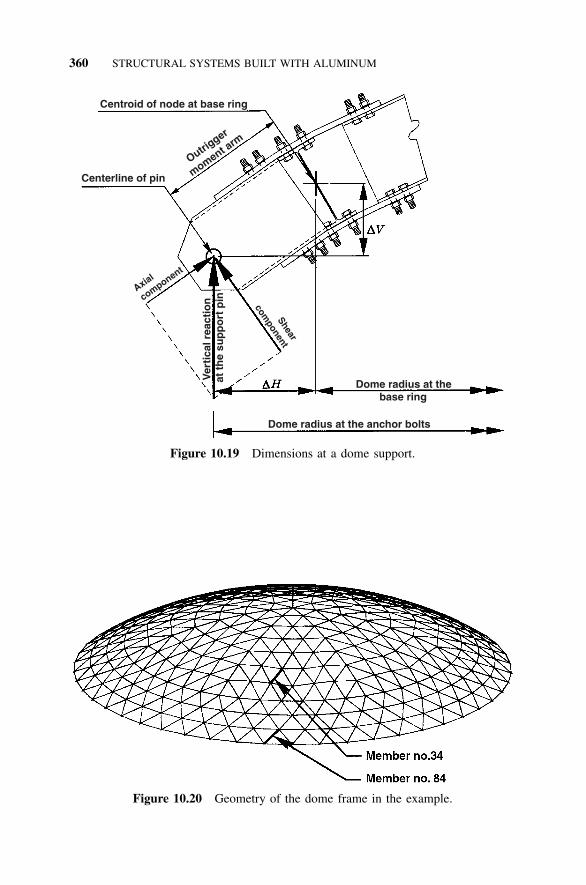
360 STRUCTURAL SYSTEMS BUILT WITH ALUMINUM
Centroid of node at base ring
Centerline of pin O
utrigger
moment arm
Axial
component
Ver
tica
l rea
ctio
nat
th
e su
pp
ort
pin Shear
component
Dome radius at the base ring
Dome radius at the anchor bolts
Figure 10.19 Dimensions at a dome support.
Figure 10.20 Geometry of the dome frame in the example.
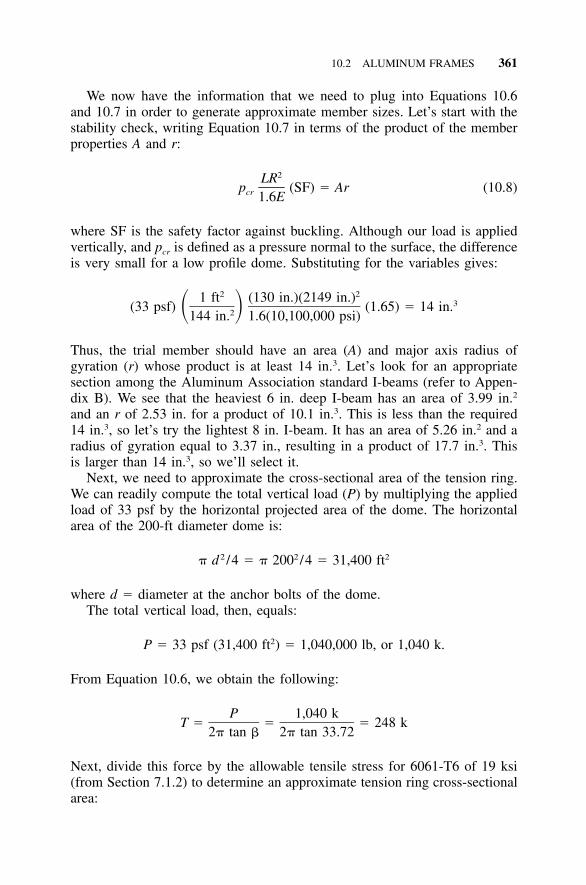
10.2 ALUMINUM FRAMES 361
We now have the information that we need to plug into Equations 10.6and 10.7 in order to generate approximate member sizes. Let’s start with thestability check, writing Equation 10.7 in terms of the product of the memberproperties A and r:
2LRp (SF) � Ar (10.8)cr 1.6E
where SF is the safety factor against buckling. Although our load is appliedvertically, and pcr is defined as a pressure normal to the surface, the differenceis very small for a low profile dome. Substituting for the variables gives:
2 21 ft (130 in.)(2149 in.) 3(33 psf) (1.65) � 14 in.� �2144 in. 1.6(10,100,000 psi)
Thus, the trial member should have an area (A) and major axis radius ofgyration (r) whose product is at least 14 in.3. Let’s look for an appropriatesection among the Aluminum Association standard I-beams (refer to Appen-dix B). We see that the heaviest 6 in. deep I-beam has an area of 3.99 in.2
and an r of 2.53 in. for a product of 10.1 in.3. This is less than the required14 in.3, so let’s try the lightest 8 in. I-beam. It has an area of 5.26 in.2 and aradius of gyration equal to 3.37 in., resulting in a product of 17.7 in.3. Thisis larger than 14 in.3, so we’ll select it.
Next, we need to approximate the cross-sectional area of the tension ring.We can readily compute the total vertical load (P) by multiplying the appliedload of 33 psf by the horizontal projected area of the dome. The horizontalarea of the 200-ft diameter dome is:
2 2 2� d /4 � � 200 /4 � 31,400 ft
where d � diameter at the anchor bolts of the dome.The total vertical load, then, equals:
2P � 33 psf (31,400 ft ) � 1,040,000 lb, or 1,040 k.
From Equation 10.6, we obtain the following:
P 1,040 kT � � � 248 k
2� tan � 2� tan 33.72
Next, divide this force by the allowable tensile stress for 6061-T6 of 19 ksi(from Section 7.1.2) to determine an approximate tension ring cross-sectionalarea:
362 STRUCTURAL SYSTEMS BUILT WITH ALUMINUM
TABLE 10.6 Forces and Moments in Member No. 34
Member No. 34L � 135 in.
CompressiveAxial Force (k)
Major AxisMoment (in.-k)
Minor AxisMoment (in.-k)
Shear(k)
Top end 21.4 13.6 �0.19 0.55Mid span 21.6 �5.49 0.09 0.01Bottom end 21.8 11.7 0.37 �0.52
2Required area (A) � 248 k/19 ksi � 13 in.
We won’t select an I-beam this large; instead, we’ll use a smaller I-beam andadd reinforcement. To simplify the model, we can use the same size I-beamas that selected for the other members, but increase the area from 5.26 in.2
to 13 in.2. We’ll add the reinforcement symmetrically about the centroid ofthe tension ring, so that we don’t have to model in any eccentricity.
10.2.5 Design Checks
Although the frame has 980 members, symmetry allows us to check fewerthan 100 of them for this uniform vertical load case. That is still far moremember checks than we will grind through in this example. We will selecttwo members to illustrate the design steps. As shown in Figure 10.20, thesemembers have been identified as no. 34 and no. 84. No. 34 is one of the moreheavily loaded members other than those in the bottom bay or the tensionring. We’ll then demonstrate with member no. 84 that the bottom bay ofdiagonal members is subject to moments that differ significantly from thosein members farther from the supports.
Check Member No. 34 The forces and moments for member no. 34 aresummarized in Table 10.6 below.
Member No. 34—Axial Compression Referring to Section 7.2, we need tocheck the member as a column for both overall and local buckling. The firststep is to determine the overall column slenderness ratio. The panels providecontinuous bracing against minor axis buckling, but the full length of themember is unbraced for major axis buckling. Recalling Table 7.1 (Section7.2.1) and obtaining r from the summary of section properties in AppendixB, we can summarize the flexural buckling slenderness ratios as follows andshown in Table 10.7.
Torsional buckling is not a concern because the continuous panel attach-ments brace the members against twisting. The overall slenderness ratio, then,is 40.1. The next step is to calculate the slenderness ratios of the cross-sectional elements, which we can skip because we already have them sum-marized in Appendix D for common shapes.
10.2 ALUMINUM FRAMES 363
TABLE 10.7 Overall Column Slenderness Ratio Comparison for Member No.34—Flexural Buckling
Axis k L r kL /r
Major axis (x) 1.0 135 in. 3.37 in. 40.1Minor axis (y) 1.0 0 in. 1.18 in. 0
The overall slenderness ratio of 40.1 is between S1 and S2, so from Table7.4 (Section 7.2.3) we determine the overall column allowable stress:
20.2 � 0.126 kL /r � 20.2 � 0.126 (40.1) � 15.1 ksi
Comparing this value to the allowable stress for the elements from AppendixD:
Overall column allowable stress � 15.1 ksi
Element allowable stress � 17.6 ksi
Column allowable axial stress (Fa) � 15.1 ksi
Appendix D also indicates that none of the element slenderness ratios aregreater than S2, so we do not have to reduce the overall column allowablestress for the effect of local buckling.
We now compute the axial compressive stress (ƒa). The maximum axialforce is 21.8 k (Table 10.6), and the cross-sectional area is 5.26 in. (AppendixB). The axial compressive stress is:
ƒ � 21.8 k/5.26 in. � 4.1 ksia
Member No. 34—Major Axis Bending Having taken care of the axial load,we can check bending. Referring to Section 7.3, we’ll begin by checkingtension due to bending. For an I-beam bent about its strong axis, the allowabletensile bending stress (from Section 7.3.1) is 19 ksi.
As with all tension considerations, the calculated stresses are based on thenet area (refer to Section 5.1 for calculating the net area). When tension iscaused by bending, it occurs in only one flange while compression is inducedin the other. The net section for tension bending, then, needs only to have thebolt hole deductions applied to the tension flange. To simplify the calcula-tions, however, we will deduct holes from both flanges to compute a netsection. Assuming two in. diameter bolts in each row of bolts, the I 8 �1–26.18 trial member has a net section modulus of 11.8 in.3. The tensile bendingstress (ƒbtx) is then:
3ƒ � 13.6 in.-k/11.8 in. � 1.15 ksibtx
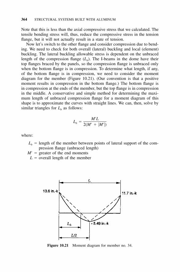
364 STRUCTURAL SYSTEMS BUILT WITH ALUMINUM
Figure 10.21 Moment diagram for member no. 34.
Note that this is less than the axial compressive stress that we calculated. Thetensile bending stress will, thus, reduce the compressive stress in the tensionflange, but it will not actually result in a state of tension.
Now let’s switch to the other flange and consider compression due to bend-ing. We need to check for both overall (lateral) buckling and local (element)buckling. The lateral buckling allowable stress is dependent on the unbracedlength of the compression flange (Lb). The I-beams in the dome have theirtop flanges braced by the panels, so the compression flange is unbraced onlywhen the bottom flange is in compression. To determine what length, if any,of the bottom flange is in compression, we need to consider the momentdiagram for the member (Figure 10.21). (Our convention is that a positivemoment results in compression in the bottom flange.) The bottom flange isin compression at the ends of the member, but the top flange is in compressionin the middle. A conservative and simple method for determining the maxi-mum length of unbraced compression flange for a moment diagram of thisshape is to approximate the curves with straight lines. We can, then, solve bysimilar triangles for Lb as follows:
M�LL �b 2(M� � M�)
where:
Lb � length of the member between points of lateral support of the com-pression flange (unbraced length)
M� � greater of the end momentsL � overall length of the member
10.2 ALUMINUM FRAMES 365
M� � absolute value of the moment at the midspan of the member.
For member no. 34:
13.6 in.-k(135 in.)L � � 48.1 in.b 2(13.6 in.-k � 5.49 in.-k)
A cautionary note is in order here. In this example, the inflection point de-termines the unbraced length because one of the flanges is continuouslybraced and the other is not. If neither flange were braced, then the inflectionpoint would not be deemed a brace point. It would indicate a change in whichflange is subject to compression, but the member would still have an unbracedcompression flange on either side of the inflection point.
The value of ry for an I 8 � 6.18 I-beam is given in Appendix B as 1.18in. The ratio Lb /ry is, then:
L /r � 48.1 in. /1.18 in. � 40.8b y
From Table 7.9 (Section 7.3.2), we see that this is between S1 and S2, and theallowable stress for lateral buckling is:
23.9 � 0.124 (L /r ) � 18.8 ksib y
Since this is 90% of the maximum allowable compressive stress (21 ksi fromTable 7.9), we won’t pursue a more precise value, even though the AluminumSpecification provides a way to do so (Section 5.3.2). Comparing to the al-lowable stress for the elements of beams from Appendix D:
Lateral buckling allowable stress � 18.8 ksi
Local buckling allowable stress � 22.7 ksi
Allowable compressive bending stress � 18.8 ksi � Fbx
We calculate the compressive bending stress (ƒbx) by dividing the major axismoment from Table 10.6 by the gross section modulus from Appendix B:
3ƒ � 13.6 in.-k/14.9 in. � 0.91 ksibx
Member No. 34—Minor Axis Bending As shown in Table 10.6, member no.34 has minor axis bending, as well as major axis bending. The allowabletensile bending stress for an I-beam bent about its weak axis is obtained fromFigure 5.43 as 28 ksi.
366 STRUCTURAL SYSTEMS BUILT WITH ALUMINUM
To determine the tensile bending stress (ƒbty), we must calculate the minoraxis section modulus using the net section. Once again, we will deduct thebolt holes from both flanges as a conservative simplification, resulting in aminor axis net section modulus of 2.8 in.3. Referring to Table 10.6, the greaterminor axis end moment occurs at the opposite end of the member from thegreater major axis end moment. Although we could check each end separatelyfor combined stresses, the moments are relatively small and we don’t wantto have to check both ends. We’ll conservatively use the larger value regard-less of where it occurs. The minor axis tensile bending stress (ƒbty) is, then:
3ƒ � 0.37 in.-k/2.8 in. � 0.13 ksibty
Combining this with the major axis tensile bending stress of 1.15 ksi producesa maximum bending tensile stress of 1.28 ksi. This is still less than the axialcompressive stress of 4.1 ksi, so the entire cross section is in a state of(nonuniform) compression.
For minor axis bending compression, we note that a beam bent about itsweak axis is not subject to lateral buckling. Furthermore, the web lies on theneutral axis, so it need not be checked for local buckling. Appendix D doesnot have values for minor axis bending allowable stresses, so we will haveto calculate the allowable local buckling stress for the flanges. We can turnto Appendix D to find that the b / t ratio of the flanges is 5.96. From Figure5.56, we see that this is less than S1, and the allowable minor axis localbuckling stress (Fby) is 28 ksi. Dividing the minor axis moment (Table 10.6)by the minor axis gross section modulus (from Appendix B), we calculate aminor axis bending stress (ƒby):
3ƒ � 0.37 in.-k/2.92 in. � 0.13 ksiby
Member No. 34—Shear Finally, let’s address shear stress. The allowableshear stress in the web is a function of its h/t ratio, which for shear in flatplate webs is based on the clear height between the flanges. From the di-mensions provided in Appendix B, we can calculate h / t as follows:
h / t � [8 in. � 2 (0.35 in.)] /0.23 in. � 31.74
Note that this is slightly greater than the b / t ratio of 29.13 given in AppendixD for the web in compression, where the fillets were deducted from the heightof the web. We see from Table 7.15 that 31.74 is less than S1, and the allow-able shear stress (Fs) is 12 ksi. The calculated shear stress is obtained fromthe approximation
ƒ � shear/(area of the web) � 0.55 k/[(7.3 in.)(0.23 in.)] � 0.33 ksis
10.2 ALUMINUM FRAMES 367
Member No. 34—Combined Stresses We’ve calculated a bunch of numbers,so let’s summarize them before moving on.
Because the member has both axial force and bending, we must check itfor combined stresses. From Section 7.4, we see that there are two cases tocheck for combined compression and bending, and another case to check forcombined shear, compression, and bending. We’ll begin with Equation 7.9:
C ƒƒ C ƒ my bya mx bx� � � 1.0F F (1 � ƒ /F ) F (1 � ƒ /F )a bx a ex by a ey
Values for all of the variables except Cm and Fe are given in Table 10.8. Allof the members that frame into a given node of a single-layer spherical latticeare within a few degrees of lying in the same plane, so we will consider thejoint to be permitted to sway (i.e., allowed to translate in the plane of bend-ing). The value of Cm is, thus, taken as 0.85, and all that remains to becalculated are Fex and Fey, given:
2� EF �e 2n (kL /r)u
where:E � modulus of elasticity (10,100 ksi)nu � safety factor on ultimate strength (1.95)
kL /r � slenderness ratio of the unsupported length in the plane of bending.Remember that this is the slenderness ratio for the member as acolumn.
Retrieving the values for (kL /r) from Table 10.7, we determine the followingvalues for Fex and Fey:
2 2F � [� (10,100 ksi)] /[1.95 (40.1) ] � 31.8 ksiex
and
2 2F � [� (10,100 ksi)] /[1.95 (0) ] � (51,100 ksi/0)ey
We’ve left Fey expressed as a ratio, so we can follow the effect of the zeroin the combined stress equation, which is now expressed as follows:
4.1 0.85(0.91) 0.85(0.13)� �
15.1 18.8(1 � 4.1/31.8) 28(1 � 4.1(0/51,100)
4.1 0.85(0.91) 0.85(0.13)� � �
15.1 18.8(0.87) 28(1)
� 0.27 � 0.047 � 0.004 � 0.32 � 1.0
The stresses in member no. 34 satisfy this first check on combined compres-sion and bending, so let’s perform the second check. Repeating Equation 7.10:
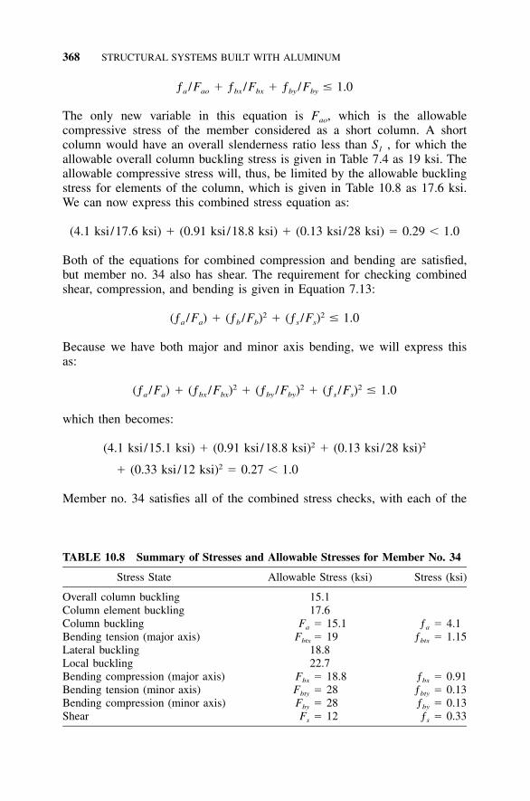
368 STRUCTURAL SYSTEMS BUILT WITH ALUMINUM
TABLE 10.8 Summary of Stresses and Allowable Stresses for Member No. 34
Stress State Allowable Stress (ksi) Stress (ksi)
Overall column buckling 15.1Column element buckling 17.6Column buckling Fa � 15.1 ƒa � 4.1Bending tension (major axis) Fbtx � 19 ƒbtx � 1.15Lateral buckling 18.8Local buckling 22.7Bending compression (major axis) Fbx � 18.8 ƒbx � 0.91Bending tension (minor axis) Fbty � 28 ƒbty � 0.13Bending compression (minor axis) Fby � 28 ƒby � 0.13Shear Fs � 12 ƒs � 0.33
ƒ /F � ƒ /F � ƒ /F � 1.0a ao bx bx by by
The only new variable in this equation is Fao, which is the allowablecompressive stress of the member considered as a short column. A shortcolumn would have an overall slenderness ratio less than S1 , for which theallowable overall column buckling stress is given in Table 7.4 as 19 ksi. Theallowable compressive stress will, thus, be limited by the allowable bucklingstress for elements of the column, which is given in Table 10.8 as 17.6 ksi.We can now express this combined stress equation as:
(4.1 ksi/17.6 ksi) � (0.91 ksi/18.8 ksi) � (0.13 ksi/28 ksi) � 0.29 � 1.0
Both of the equations for combined compression and bending are satisfied,but member no. 34 also has shear. The requirement for checking combinedshear, compression, and bending is given in Equation 7.13:
2 2(ƒ /F ) � (ƒ /F ) � (ƒ /F ) � 1.0a a b b s s
Because we have both major and minor axis bending, we will express thisas:
2 2 2(ƒ /F ) � (ƒ /F ) � (ƒ /F ) � (ƒ /F ) � 1.0a a bx bx by by s s
which then becomes:
2 2(4.1 ksi/15.1 ksi) � (0.91 ksi/18.8 ksi) � (0.13 ksi/28 ksi)2� (0.33 ksi/12 ksi) � 0.27 � 1.0
Member no. 34 satisfies all of the combined stress checks, with each of the
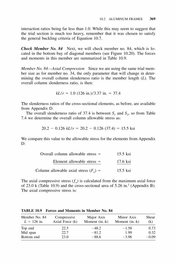
10.2 ALUMINUM FRAMES 369
TABLE 10.9 Forces and Moments in Member No. 84
Member No. 84L � 126 in.
CompressiveAxial Force (k)
Major AxisMoment (in.-k)
Minor AxisMoment (in.-k)
Shear(k)
Top end 22.5 �48.2 �1.58 0.73Mid span 22.7 �81.2 1.99 0.32Bottom end 23.0 �88.6 �3.96 �0.09
interaction ratios being far less than 1.0. While this may seem to suggest thatthe trial section is much too heavy, remember that it was chosen to satisfythe general buckling criteria of Equation 10.7.
Check Member No. 84 Next, we will check member no. 84, which is lo-cated in the bottom bay of diagonal members (see Figure 10.20). The forcesand moments in this member are summarized in Table 10.9.
Member No. 84—Axial Compression Since we are using the same trial mem-ber size as for member no. 34, the only parameter that will change in deter-mining the overall column slenderness ratio is the member length (L). Theoverall column slenderness ratio, is then:
kL /r � 1.0 (126 in.) /3.37 in. � 37.4
The slenderness ratios of the cross-sectional elements, as before, are availablefrom Appendix D.
The overall slenderness ratio of 37.4 is between S1 and S2, so from Table7.4 we determine the overall column allowable stress as:
20.2 � 0.126 kL /r � 20.2 � 0.126 (37.4) � 15.5 ksi
We compare this value to the allowable stress for the elements from AppendixD:
Overall column allowable stress � 15.5 ksi
Element allowable stress � 17.6 ksi
Column allowable axial stress (Fa) � 15.5 ksi
The axial compressive stress (ƒa) is calculated from the maximum axial forceof 23.0 k (Table 10.9) and the cross-sectional area of 5.26 in.2 (Appendix B).The axial compressive stress is:
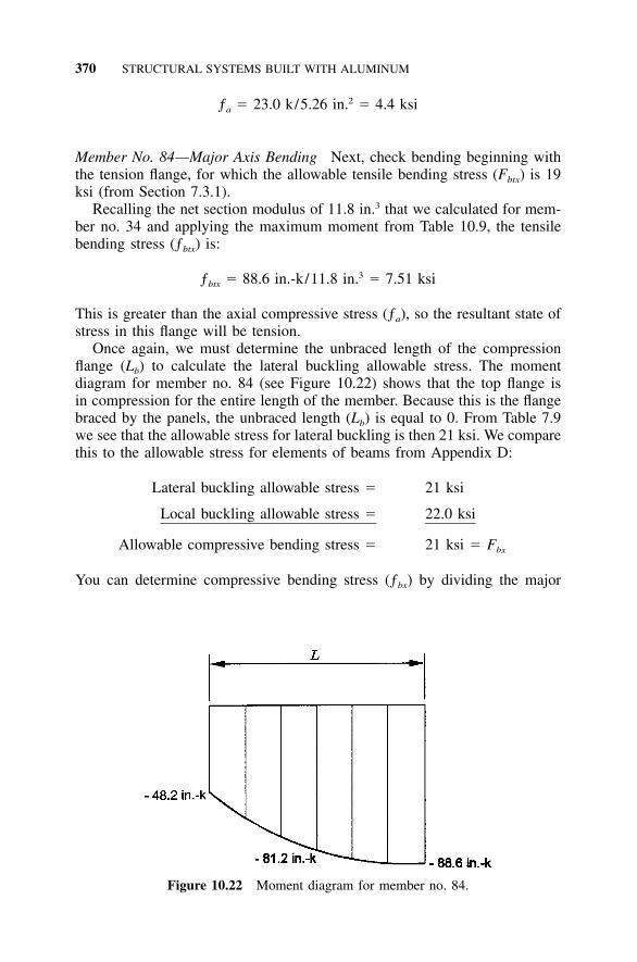
370 STRUCTURAL SYSTEMS BUILT WITH ALUMINUM
Figure 10.22 Moment diagram for member no. 84.
2ƒ � 23.0 k/5.26 in. � 4.4 ksia
Member No. 84—Major Axis Bending Next, check bending beginning withthe tension flange, for which the allowable tensile bending stress (Fbtx) is 19ksi (from Section 7.3.1).
Recalling the net section modulus of 11.8 in.3 that we calculated for mem-ber no. 34 and applying the maximum moment from Table 10.9, the tensilebending stress (ƒbtx) is:
3ƒ � 88.6 in.-k/11.8 in. � 7.51 ksibtx
This is greater than the axial compressive stress (ƒa), so the resultant state ofstress in this flange will be tension.
Once again, we must determine the unbraced length of the compressionflange (Lb) to calculate the lateral buckling allowable stress. The momentdiagram for member no. 84 (see Figure 10.22) shows that the top flange isin compression for the entire length of the member. Because this is the flangebraced by the panels, the unbraced length (Lb) is equal to 0. From Table 7.9we see that the allowable stress for lateral buckling is then 21 ksi. We comparethis to the allowable stress for elements of beams from Appendix D:
Lateral buckling allowable stress � 21 ksi
Local buckling allowable stress � 22.0 ksi
Allowable compressive bending stress � 21 ksi � Fbx
You can determine compressive bending stress (ƒbx) by dividing the major
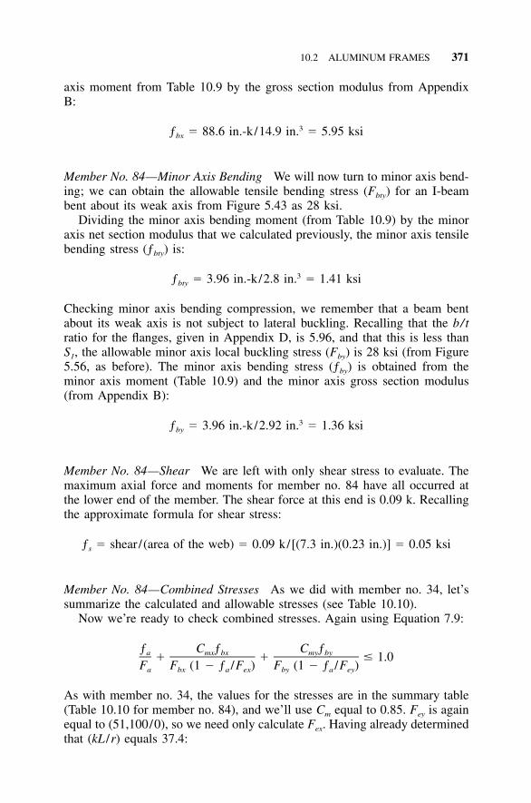
10.2 ALUMINUM FRAMES 371
axis moment from Table 10.9 by the gross section modulus from AppendixB:
3ƒ � 88.6 in.-k/14.9 in. � 5.95 ksibx
Member No. 84—Minor Axis Bending We will now turn to minor axis bend-ing; we can obtain the allowable tensile bending stress (Fbty) for an I-beambent about its weak axis from Figure 5.43 as 28 ksi.
Dividing the minor axis bending moment (from Table 10.9) by the minoraxis net section modulus that we calculated previously, the minor axis tensilebending stress (ƒbty) is:
3ƒ � 3.96 in.-k/2.8 in. � 1.41 ksibty
Checking minor axis bending compression, we remember that a beam bentabout its weak axis is not subject to lateral buckling. Recalling that the b/tratio for the flanges, given in Appendix D, is 5.96, and that this is less thanS1, the allowable minor axis local buckling stress (Fby) is 28 ksi (from Figure5.56, as before). The minor axis bending stress (ƒby) is obtained from theminor axis moment (Table 10.9) and the minor axis gross section modulus(from Appendix B):
3ƒ � 3.96 in.-k/2.92 in. � 1.36 ksiby
Member No. 84—Shear We are left with only shear stress to evaluate. Themaximum axial force and moments for member no. 84 have all occurred atthe lower end of the member. The shear force at this end is 0.09 k. Recallingthe approximate formula for shear stress:
ƒ � shear/(area of the web) � 0.09 k/[(7.3 in.)(0.23 in.)] � 0.05 ksis
Member No. 84—Combined Stresses As we did with member no. 34, let’ssummarize the calculated and allowable stresses (see Table 10.10).
Now we’re ready to check combined stresses. Again using Equation 7.9:
ƒ C ƒ C ƒa mx bx my by� � � 1.0F F (1 � ƒ /F ) F (1 � ƒ /F )a bx a ex by a ey
As with member no. 34, the values for the stresses are in the summary table(Table 10.10 for member no. 84), and we’ll use Cm equal to 0.85. Fey is againequal to (51,100/0), so we need only calculate Fex. Having already determinedthat (kL /r) equals 37.4:
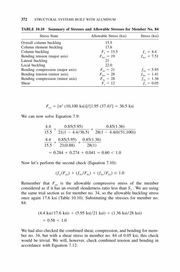
372 STRUCTURAL SYSTEMS BUILT WITH ALUMINUM
TABLE 10.10 Summary of Stresses and Allowable Stresses for Member No. 84
Stress State Allowable Stress (ksi) Stress (ksi)
Overall column buckling 15.5Column element buckling 17.6Column buckling Fa � 15.5 ƒa � 4.4Bending tension (major axis) Fbtx � 19 ƒbtx � 7.51Lateral buckling 21Local buckling 22.0Bending compression (major axis) Fbx � 21 ƒbx � 5.95Bending tension (minor axis) Fbty � 28 ƒbty � 1.41Bending compression (minor axis) Fby � 28 ƒby � 1.36Shear Fs � 12 ƒs � 0.05
2 2F � [� (10,100 ksi)] /[1.95 (37.4) ] � 36.5 ksiex
We can now solve Equation 7.9:
4.4 0.85(5.95) 0.85(1.36)� �
15.5 21(1 � 4.4/36.5) 28(1 � 4.4(0/51,100))
4.4 0.85(5.95) 0.85(1.36)� �
15.5 21(0.88) 28(1)
� 0.284 � 0.274 � 0.041 � 0.60 � 1.0
Now let’s perform the second check (Equation 7.10):
(ƒ /F ) � (ƒ /F ) � (ƒ /F ) � 1.0a ao bx bx by by
Remember that Fao is the allowable compressive stress of the memberconsidered as if it has an overall slenderness ratio less than S1 . We are usingthe same trial section as for member no. 34, so the allowable buckling stressonce again 17.6 ksi (Table 10.10). Substituting the stresses for member no.84:
(4.4 ksi/17.6 ksi) � (5.95 ksi/21 ksi) � (1.36 ksi/28 ksi)
� 0.58 � 1.0
We had also checked the combined shear, compression, and bending for mem-ber no. 34, but with a shear stress in member no. 84 of 0.05 ksi, this checkwould be trivial. We will, however, check combined tension and bending inaccordance with Equation 7.12:
10.3 ALUMINUM COMPOSITE MEMBERS 373
(ƒ /F ) � (ƒ /F ) � (ƒ /F ) � 1.0t t btx btx bty bty
We will take the ratio (ƒt /Ft) as 0 since the axial load is compression. Thisis quite conservative because the axial compression would act to reduce thetensile stresses. Our tensile bending stresses are not large, however, so wecan stand a conservative simplification. Applying the values from Table 10.10,we have:
(7.51 ksi/19 ksi) � (1.41 ksi/28 ksi) � 0.45 � 1.0
Although member no. 84 satisfies all of the combined stress checks, the in-teraction ratios are about twice those for member no. 34. The larger stressesin member no. 84 are due to the moment induced by the outrigger detail atthe support. Alternate support details could minimize this boundary condition.
Note also that even the higher interaction ratios of member no. 84 are stillwell below 1.0. The general buckling criteria of Equation 10.7 govern thesizing of these two members for this load case. These members were selectedas representing the more highly stressed members in the dome, so it appearsthat general buckling is a more critical limit state than the calculated stresses,for all members other than those in the tension ring.
While we selected a standard I-beam for our design checks, recall that theproduct of its area (A) and radius of gyration (r) was 17.7 in.3 and the re-quirement for resisting general buckling was 14 in.3. The standard I-beam,therefore, has more than 25% excess material, and it does not have the specialribs on the top flange to engage the panel and batten bar. Real-world designengineers would modify the section to make it more efficient, add the ribs tothe top flange, and order it as a custom extrusion.
This example is intended to demonstrate the application of the design re-quirements of the Aluminum Specification—it should not be considered acomprehensive review of the design requirements of aluminum domes. As-sumptions made for the sake of the illustration do not apply to every memberin the dome nor to every load case that may be applied to it.
10.3 ALUMINUM COMPOSITE MEMBERS
Aluminum is often used in combination with other materials, for example, analuminum I-beam might be reinforced with a steel cover plate, or an alumi-num bar might be used to reinforce a wood member. You have to addresspotential corrosion issues that dissimilar material contact can cause (see Sec-tion 10.3.3), but once that’s done you have to do what you’re really paidfor—the structural design. This section provides some examples. Once youhave determined the forces and moments in the various materials, use theappropriate design standard for each material to determine if it’s adequatelysized.
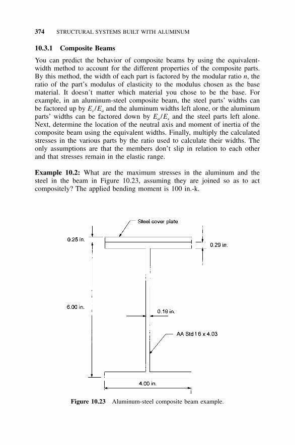
374 STRUCTURAL SYSTEMS BUILT WITH ALUMINUM
Figure 10.23 Aluminum-steel composite beam example.
10.3.1 Composite Beams
You can predict the behavior of composite beams by using the equivalent-width method to account for the different properties of the composite parts.By this method, the width of each part is factored by the modular ratio n, theratio of the part’s modulus of elasticity to the modulus chosen as the basematerial. It doesn’t matter which material you chose to be the base. Forexample, in an aluminum-steel composite beam, the steel parts’ widths canbe factored up by Es /Ea and the aluminum widths left alone, or the aluminumparts’ widths can be factored down by Ea /Es and the steel parts left alone.Next, determine the location of the neutral axis and moment of inertia of thecomposite beam using the equivalent widths. Finally, multiply the calculatedstresses in the various parts by the ratio used to calculate their widths. Theonly assumptions are that the members don’t slip in relation to each otherand that stresses remain in the elastic range.
Example 10.2: What are the maximum stresses in the aluminum and thesteel in the beam in Figure 10.23, assuming they are joined so as to actcompositely? The applied bending moment is 100 in.-k.
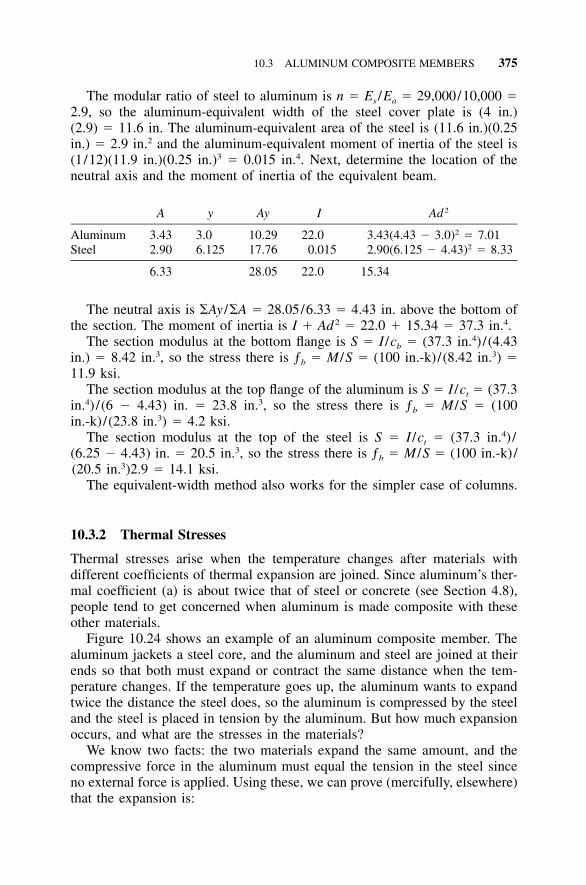
10.3 ALUMINUM COMPOSITE MEMBERS 375
The modular ratio of steel to aluminum is n � Es /Ea � 29,000/10,000 �2.9, so the aluminum-equivalent width of the steel cover plate is (4 in.)(2.9) � 11.6 in. The aluminum-equivalent area of the steel is (11.6 in.)(0.25in.) � 2.9 in.2 and the aluminum-equivalent moment of inertia of the steel is(1/12)(11.9 in.)(0.25 in.)3 � 0.015 in.4. Next, determine the location of theneutral axis and the moment of inertia of the equivalent beam.
A y Ay I Ad 2
Aluminum 3.43 3.0 10.29 22.0 3.43(4.43 � 3.0)2 � 7.01Steel 2.90 6.125 17.76 0.015 2.90(6.125 � 4.43)2 � 8.33
6.33 28.05 22.0 15.34
The neutral axis is �Ay /�A � 28.05/6.33 � 4.43 in. above the bottom ofthe section. The moment of inertia is I � Ad2 � 22.0 � 15.34 � 37.3 in.4.
The section modulus at the bottom flange is S � I /cb � (37.3 in.4) /(4.43in.) � 8.42 in.3, so the stress there is ƒb � M /S � (100 in.-k)/(8.42 in.3) �11.9 ksi.
The section modulus at the top flange of the aluminum is S � I /ct � (37.3in.4) /(6 � 4.43) in. � 23.8 in.3, so the stress there is ƒb � M /S � (100in.-k)/(23.8 in.3) � 4.2 ksi.
The section modulus at the top of the steel is S � I /ct � (37.3 in.4) /(6.25 � 4.43) in. � 20.5 in.3, so the stress there is ƒb � M /S � (100 in.-k)/(20.5 in.3)2.9 � 14.1 ksi.
The equivalent-width method also works for the simpler case of columns.
10.3.2 Thermal Stresses
Thermal stresses arise when the temperature changes after materials withdifferent coefficients of thermal expansion are joined. Since aluminum’s ther-mal coefficient (a) is about twice that of steel or concrete (see Section 4.8),people tend to get concerned when aluminum is made composite with theseother materials.
Figure 10.24 shows an example of an aluminum composite member. Thealuminum jackets a steel core, and the aluminum and steel are joined at theirends so that both must expand or contract the same distance when the tem-perature changes. If the temperature goes up, the aluminum wants to expandtwice the distance the steel does, so the aluminum is compressed by the steeland the steel is placed in tension by the aluminum. But how much expansionoccurs, and what are the stresses in the materials?
We know two facts: the two materials expand the same amount, and thecompressive force in the aluminum must equal the tension in the steel sinceno external force is applied. Using these, we can prove (mercifully, elsewhere)that the expansion is:
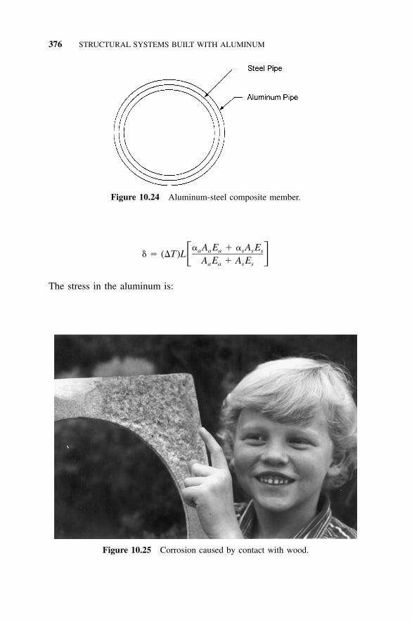
376 STRUCTURAL SYSTEMS BUILT WITH ALUMINUM
Figure 10.24 Aluminum-steel composite member.
Figure 10.25 Corrosion caused by contact with wood.
� A E � � A Ea a a s s s� � (�T)L� �A E � A Ea a s s
The stress in the aluminum is:
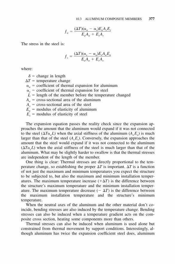
10.3 ALUMINUM COMPOSITE MEMBERS 377
(�T)(� � � )E A Ea s a s sƒ �a E A � E Aa a s s
The stress in the steel is:
(�T)(� � � )E A Es a s a aƒ �s E A � E Aa a s s
where:
� � change in length�T � temperature change�a � coefficient of thermal expansion for aluminum�s � coefficient of thermal expansion for steelL � length of the member before the temperature changed
Aa � cross-sectional area of the aluminumAs � cross-sectional area of the steelEa � modulus of elasticity of aluminumEs � modulus of elasticity of steel
The expansion equation passes the reality check since the expansion ap-proaches the amount that the aluminum would expand if it was not connectedto the steel (�T�aL) when the axial stiffness of the aluminum (AaEa) is muchlarger than that of the steel (AsEs). Conversely, the expansion approaches theamount that the steel would expand if it was not connected to the aluminum(�T�sL) when the axial stiffness of the steel is much larger than that of thealuminum. What may be slightly harder to swallow is that the thermal stressesare independent of the length of the member.
One thing is clear: Thermal stresses are directly proportional to the tem-perature change, so establishing the proper �T is important. �T is a functionof not just the maximum and minimum temperatures you expect the structureto be subjected to, but also the maximum and minimum installation temper-atures. The maximum temperature increase (��T) is the difference betweenthe structure’s maximum temperature and the minimum installation temper-ature. The maximum temperature decrease (� �T) is the difference betweenthe maximum installation temperature and the structure’s minimumtemperature.
When the neutral axes of the aluminum and the other material don’t co-incide, bending stresses are also induced by the temperature change. Bendingstresses can also be induced when a temperature gradient acts on the com-posite cross section, heating some components more than others.
Thermal stresses can also be induced when aluminum is used alone butconstrained from thermal movement by support conditions. Interestingly, al-though aluminum has twice the expansion coefficient steel does, aluminum
378 STRUCTURAL SYSTEMS BUILT WITH ALUMINUM
stresses will be two-thirds that of steel in the same restraint since aluminum’smodulus of elasticity is one-third that of steel.
Thermal stresses are self-limiting because if they exceed the yield strength,the force is relieved by the resulting deformation. The Aluminum Specifica-tion doesn’t address this by providing different allowable stresses for thermalloads, but ASCE 7’s load and resistance factor design (LRFD) combinationsprescribe a low load factor (1.2) on self-straining forces (T), which includethermal loads.
10.3.3 Dissimilar Material Contact
Dissimilar material contact is one of the most talked about and least under-stood aspects of using aluminum. We mentioned it in Section 8.1.3 on fas-teners, but the situation arises in a different manner in composite membersand wherever aluminum is placed immediately adjacent to other materials. Inthese situations, contact isn’t limited to a small area as for fasteners.
Dissimilar materials can cause corrosion of the aluminum in several ways.If the material is cathodic to aluminum and moisture is present, galvaniccorrosion of the aluminum will occur. Other materials, such as wood or con-crete, can cause corrosion of aluminum by holding moisture against the alu-minum. Galvanic corrosion occurs when materials of different electrical po-tential are in contact through an electrolyte, which can be provided bymoisture. Most metals other than zinc, magnesium, and cadmium are cathodicto aluminum, although austenitic stainless steels tend to have little galvaniceffect on aluminum despite their position on the galvanic series. Contact withbrass, bronze, and copper should be especially avoided as they cause vigorousgalvanic attack of aluminum. Some practical guidelines for contact with var-ious materials are listed below. Aluminum Specification Sections 6.6 and 6.7also address this issue. In all cases, you can improve the corrosion resistanceby sealing the contact area from moisture. Silicone, polysulfide, or butyl seal-ants can be used with aluminum; the choice depends on the intended service.
Carbon Steel Prevent contact with carbon steel by coating the steel with azinc-based primer. Zinc provides cathodic protection for both the aluminumand the steel. Other paints suitable for steel in the intended service are alsoused.
Concrete and Masonry Where aluminum is in contact with concrete, ma-sonry, plaster, or other alkaline material and the assembly is exposed to mois-ture, the aluminum should be coated. You can use zinc-based paint, clearlacquer, or bituminous paint. Bituminous paint is relatively inexpensive, so athick coating can be economically applied. Some concrete additives, such aschlorides, are corrosive to aluminum and should be avoided. Products, suchas magnesium phosphate grout, that are designed to remain at a relatively lowpH during and after curing are compatible with uncoated aluminum.
10.4 ALUMINUM PRESSURE PIPING 379
Wood Aluminum can be corroded by the moisture in wood or chemicalpreservatives in treated wood and can be protected by painting the aluminumwith any of the paints used for aluminum or a bituminous paint.
Soil In many cases, aluminum may be used in direct contact with soil with-out protection. While the 2xxx series alloys are not suitable for this, suchalloys as Alclad 3004, 5052, 6061 and 6063 are used in the ground withoutcoatings and generally suffer only slight pitting corrosion whose rate de-creases over time. Aluminum light poles have been driven directly into theground, buried aluminum pipe has been used in the oil industry, and corru-gated aluminum pipe and culvert are common (see Section 3.1.5). The Alu-minum Association Drainage Products Manual(s) recommends the followingconditions be met to minimize corrosion in soils:
1) Soil and water pH should be between 4 and 9.2) Soil and water resistivities should be 500 ohm-cm or greater.3) Aluminum should not be in electrical contact with dissimilar metals.4) Aluminum should not be used in clay-muck soils containing organic
materials.5) Aluminum should be isolated from stray electrical currents.
Runoff from Heavy Metals Heavy metals, such as copper and lead, arecorrosive to aluminum, so aluminum should not be exposed to rain waterrunoff from copper or terne-coated steel, which has a lead and tin coating.
10.4 ALUMINUM PRESSURE PIPING
Aluminum pressure piping used in: petroleum refineries; chemical, pharma-ceutical, textile, paper, semiconductor, and cryogenic plants; and related proc-essing plants and terminals is addressed by ASME B31.3, Process Piping,the ASME code for piping with internal gage pressures of 15 psi [105 kPa]or greater (84). This code uses the allowable stress method for structuraldesign and includes certain aluminum alloys and tempers in certain productforms.
For straight pipe under internal pressure and with a design wall thicknessless than one-sixth the outside diameter (t � D /6), B31.3 establishes thedesign wall thickness as the greater of:
PDt �
2(SE � PY)
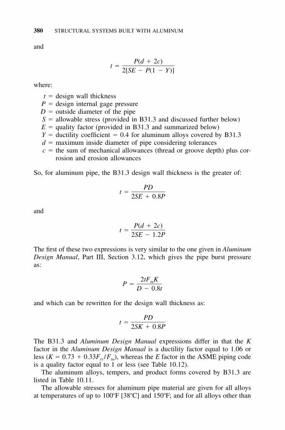
380 STRUCTURAL SYSTEMS BUILT WITH ALUMINUM
and
P(d � 2c)t �
2[SE � P(1 � Y)]
where:
t � design wall thicknessP � design internal gage pressureD � outside diameter of the pipeS � allowable stress (provided in B31.3 and discussed further below)E � quality factor (provided in B31.3 and summarized below)Y � ductility coefficient � 0.4 for aluminum alloys covered by B31.3d � maximum inside diameter of pipe considering tolerancesc � the sum of mechanical allowances (thread or groove depth) plus cor-
rosion and erosion allowances
So, for aluminum pipe, the B31.3 design wall thickness is the greater of:
PDt �
2SE � 0.8P
and
P(d � 2c)t �
2SE � 1.2P
The first of these two expressions is very similar to the one given in AluminumDesign Manual, Part III, Section 3.12, which gives the pipe burst pressureas:
2tF KtuP �D � 0.8t
and which can be rewritten for the design wall thickness as:
PDt �
2SK � 0.8P
The B31.3 and Aluminum Design Manual expressions differ in that the Kfactor in the Aluminum Design Manual is a ductility factor equal to 1.06 orless (K � 0.73 � 0.33Fty /Ftu), whereas the E factor in the ASME piping codeis a quality factor equal to 1 or less (see Table 10.12).
The aluminum alloys, tempers, and product forms covered by B31.3 arelisted in Table 10.11.
The allowable stresses for aluminum pipe material are given for all alloysat temperatures of up to 100�F [38�C] and 150�F; and for all alloys other than
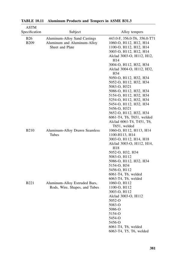
381
TABLE 10.11 Aluminum Products and Tempers in ASME B31.3
ASTMSpecification Subject Alloy tempers
B26 Aluminum-Alloy Sand Castings 443.0-F, 356.0-T6, 356.0-T71B209 Aluminum and Aluminum-Alloy
Sheet and Plate1060-O, H112, H12, H141100-O, H112, H12, H143003-O, H112, H12, H14Alclad 3003-O, H112, H12,
H143004-O, H112, H32, H34Alclad 3004-O, H112, H32,
H345050-O, H112, H32, H345052-O, H112, H32, H345083-O, H3215086-O, H112, H32, H345154-O, H112, H32, H345254-O, H112, H32, H345454-O, H112, H32, H345456-O, H3215652-O, H112, H32, H346061-T4, T6, T651, weldedAlclad 6061-T4, T451, T6,
T651, weldedB210 Aluminum-Alloy Drawn Seamless
Tubes1060-O, H112, H113, H141100-H113, H143003-O, H112, H14, H18Alclad 3003-O, H112, H14,
H185052-O, H32, H345083-O, H1125086-O, H112, H32, H345154-O, H345456-O, H1126061-T4, T6, welded6063-T4, T6, welded
B221 Aluminum-Alloy Extruded Bars,Rods, Wire, Shapes, and Tubes
1060-O, H1121100-O, H1123003-O, H112Alclad 3003-O, H1125052-O5083-O5086-O5154-O5454-O5456-O6061-T4, T6, welded6063-T4, T5, T6, welded
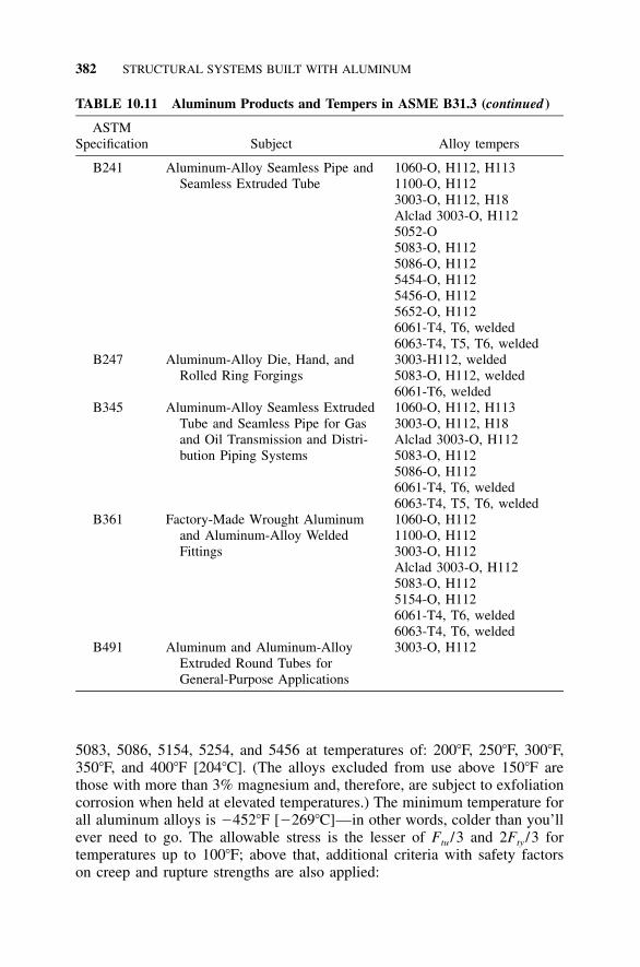
382 STRUCTURAL SYSTEMS BUILT WITH ALUMINUM
TABLE 10.11 Aluminum Products and Tempers in ASME B31.3 (continued )
ASTMSpecification Subject Alloy tempers
B241 Aluminum-Alloy Seamless Pipe andSeamless Extruded Tube
1060-O, H112, H1131100-O, H1123003-O, H112, H18Alclad 3003-O, H1125052-O5083-O, H1125086-O, H1125454-O, H1125456-O, H1125652-O, H1126061-T4, T6, welded6063-T4, T5, T6, welded
B247 Aluminum-Alloy Die, Hand, andRolled Ring Forgings
3003-H112, welded5083-O, H112, welded6061-T6, welded
B345 Aluminum-Alloy Seamless ExtrudedTube and Seamless Pipe for Gasand Oil Transmission and Distri-bution Piping Systems
1060-O, H112, H1133003-O, H112, H18Alclad 3003-O, H1125083-O, H1125086-O, H1126061-T4, T6, welded6063-T4, T5, T6, welded
B361 Factory-Made Wrought Aluminumand Aluminum-Alloy WeldedFittings
1060-O, H1121100-O, H1123003-O, H112Alclad 3003-O, H1125083-O, H1125154-O, H1126061-T4, T6, welded6063-T4, T6, welded
B491 Aluminum and Aluminum-AlloyExtruded Round Tubes forGeneral-Purpose Applications
3003-O, H112
5083, 5086, 5154, 5254, and 5456 at temperatures of: 200�F, 250�F, 300�F,350�F, and 400�F [204�C]. (The alloys excluded from use above 150�F arethose with more than 3% magnesium and, therefore, are subject to exfoliationcorrosion when held at elevated temperatures.) The minimum temperature forall aluminum alloys is �452�F [�269�C]—in other words, colder than you’llever need to go. The allowable stress is the lesser of Ftu /3 and 2Fty /3 fortemperatures up to 100�F; above that, additional criteria with safety factorson creep and rupture strengths are also applied:
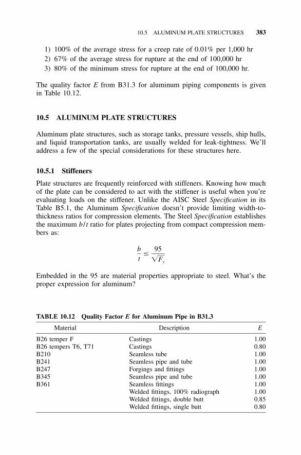
10.5 ALUMINUM PLATE STRUCTURES 383
TABLE 10.12 Quality Factor E for Aluminum Pipe in B31.3
Material Description E
B26 temper F Castings 1.00B26 tempers T6, T71 Castings 0.80B210 Seamless tube 1.00B241 Seamless pipe and tube 1.00B247 Forgings and fittings 1.00B345 Seamless pipe and tube 1.00B361 Seamless fittings 1.00
Welded fittings, 100% radiograph 1.00Welded fittings, double butt 0.85Welded fittings, single butt 0.80
1) 100% of the average stress for a creep rate of 0.01% per 1,000 hr2) 67% of the average stress for rupture at the end of 100,000 hr3) 80% of the minimum stress for rupture at the end of 100,000 hr.
The quality factor E from B31.3 for aluminum piping components is givenin Table 10.12.
10.5 ALUMINUM PLATE STRUCTURES
Aluminum plate structures, such as storage tanks, pressure vessels, ship hulls,and liquid transportation tanks, are usually welded for leak-tightness. We’lladdress a few of the special considerations for these structures here.
10.5.1 Stiffeners
Plate structures are frequently reinforced with stiffeners. Knowing how muchof the plate can be considered to act with the stiffener is useful when you’reevaluating loads on the stiffener. Unlike the AISC Steel Specification in itsTable B5.1, the Aluminum Specification doesn’t provide limiting width-to-thickness ratios for compression elements. The Steel Specification establishesthe maximum b / t ratio for plates projecting from compact compression mem-bers as:
b 95�
t �Fy
Embedded in the 95 are material properties appropriate to steel. What’s theproper expression for aluminum?
384 STRUCTURAL SYSTEMS BUILT WITH ALUMINUM
The buckling strength of a plate is:
2k� EF �cr 2 212(1 � v )(b / t)
Setting the buckling strength of the plate equal to the yield strength willprevent buckling of the plate, which means the member is compact. Doingthis, setting
95b / t � ,
�Fy
and using the appropriate material properties for steel (E � 29,000 ksi andv � 0.3) gives:
2k� (29,000)F �y 2 212(1 � 0.3 )95 /Fy
Solving this expression for k:
2 212(1 � 0.3 )95k � � 0.3442� (29,000)
Next, evaluating the buckling strength equation for aluminum with k � 0.344and setting the buckling strength equal to the yield strength:
2 2k� E 0.344� (10,000)F � �y 2 2 2 212(1 � v )(b / t) 12(1 � 0.3 )(b / t)
gives the expression for b / t:
b 0.344(10,000) 56� � � for aluminum.2�t 12(1 � 0.3 )F �Fy y
For 6061-T6 with a yield strength Fy � 35 ksi, the length of the plate oneither side of the stiffener attachment point that can be considered to act withthe stiffener is:
56t 56tb � � � 9.5t
�F �35y
compared to:
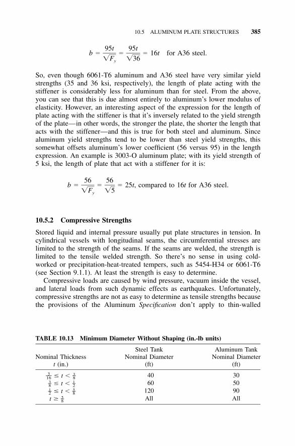
10.5 ALUMINUM PLATE STRUCTURES 385
TABLE 10.13 Minimum Diameter Without Shaping (in.-lb units)
Nominal Thicknesst (in.)
Steel TankNominal Diameter
(ft)
Aluminum TankNominal Diameter
(ft)
� t �3 3–– –16 8 40 30� t �3 1– –8 2 60 50� t �1 5– –2 8 120 90
t � 5–8 All All
95t 95tb � � � 16t for A36 steel.
�F �36y
So, even though 6061-T6 aluminum and A36 steel have very similar yieldstrengths (35 and 36 ksi, respectively), the length of plate acting with thestiffener is considerably less for aluminum than for steel. From the above,you can see that this is due almost entirely to aluminum’s lower modulus ofelasticity. However, an interesting aspect of the expression for the length ofplate acting with the stiffener is that it’s inversely related to the yield strengthof the plate—in other words, the stronger the plate, the shorter the length thatacts with the stiffener—and this is true for both steel and aluminum. Sincealuminum yield strengths tend to be lower than steel yield strengths, thissomewhat offsets aluminum’s lower coefficient (56 versus 95) in the lengthexpression. An example is 3003-O aluminum plate; with its yield strength of5 ksi, the length of plate that act with a stiffener for it is:
56 56b � � � 25t, compared to 16t for A36 steel.
�F �5y
10.5.2 Compressive Strengths
Stored liquid and internal pressure usually put plate structures in tension. Incylindrical vessels with longitudinal seams, the circumferential stresses arelimited to the strength of the seams. If the seams are welded, the strength islimited to the tensile welded strength. So there’s no sense in using cold-worked or precipitation-heat-treated tempers, such as 5454-H34 or 6061-T6(see Section 9.1.1). At least the strength is easy to determine.
Compressive loads are caused by wind pressure, vacuum inside the vessel,and lateral loads from such dynamic effects as earthquakes. Unfortunately,compressive strengths are not as easy to determine as tensile strengths becausethe provisions of the Aluminum Specification don’t apply to thin-walled
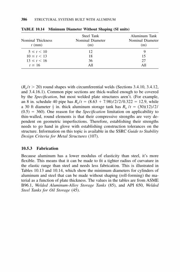
386 STRUCTURAL SYSTEMS BUILT WITH ALUMINUM
TABLE 10.14 Minimum Diameter Without Shaping (SI units)
Nominal Thicknesst (mm)
Steel TankNominal Diameter
(m)
Aluminum TankNominal Diameter
(m)
5 � t � 10 12 910 � t � 13 18 1513 � t � 16 36 27
t � 16 All All
(Rb / t � 20) round shapes with circumferential welds (Sections 3.4.10, 3.4.12,and 3.4.16.1). Common pipe sections are thick-walled enough to be coveredby the Specification, but most welded plate structures aren’t. (For example,an 8 in. schedule 40 pipe has Rb / t � (8.63 � 7.98)/2/2/0.322 � 12.9, whilea 30 ft diameter in. thick aluminum storage tank has Rb / t � (30)(12)/2/1–2(0.5) � 360). One reason for the Specification limitation on applicability tothin-walled, round elements is that their compressive strengths are very de-pendent on geometric imperfections. Therefore, establishing their strengthsneeds to go hand in glove with establishing construction tolerances on thestructure. Information on this topic is available in the SSRC Guide to StabilityDesign Criteria for Metal Structures (107).
10.5.3 Fabrication
Because aluminum has a lower modulus of elasticity than steel, it’s moreflexible. This means that it can be made to fit a tighter radius of curvature inthe elastic range than steel and needs less fabrication. This is illustrated inTables 10.13 and 10.14, which show the minimum diameters for cylinders ofaluminum and steel that can be made without shaping (roll-forming) the ma-terial as a function of plate thickness. The values in the tables are from ASMEB96.1, Welded Aluminum-Alloy Storage Tanks (85), and API 650, WeldedSteel Tanks for Oil Storage (45).
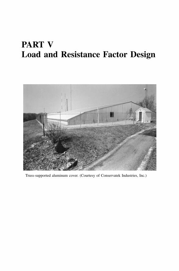
PART VLoad and Resistance Factor Design
Truss-supported aluminum cover. (Courtesy of Conservatek Industries, Inc.)

389
11 Load and ResistanceFactor Design
11.1 NEW TRICKS FOR OLD DOGS
By now you’ve undoubtedly heard of load and resistance factor design(LRFD), and you’re probably either already using it with steel or else you’rehoping that if you ignore it, it will go away. (After all, that seems to haveworked so far for converting to metric.) The whole subject was largely a mootpoint for aluminum designers, however, since no aluminum LRFD code wasavailable in the U.S. up until 1994. Now that there’s an aluminum LRFDspecification, those of you who have been able to avoid it may be eyeing thegathering cloud uneasily.
Actually, it isn’t all that bad. You really don’t need to relearn structuralengineering to use LRFD. If you’re still skeptical, give us a chance to provethis to you. You may, in fact, have already learned the fundamentals of LRFDunder its alias when used for concrete: strength design. It may be comfortingto know that load and resistance factor design is simply the metal equivalentto strength design, taught in most engineering colleges since around 1970 forconcrete.
In the beginning, designers in all materials used allowable stress design(ASD), a method of proportioning structural components in order to limitstresses under nominal loads to the yield or ultimate strength divided by asafety factor. Strength design, or LRFD, started in the 1960s in concretewhere dead load is a significant part of the total load. Concrete designersseeking more efficient structures reasoned that there should to be a way tojustify lower safety factors for well-known loads, such as that big dead load,versus the margins required for the more variable live load. They also foundit inconvenient to calculate stresses in concrete, with its nonlinear stress-straincurve and low tensile strength. Instead, they preferred to determine the ca-pacity of concrete members in terms of the ultimate force or moment(strength) that the members were able to sustain.
While strength design replaced the working stress method for concretedesign, steel designers resisted the new philosophy. The benefits were not aspotentially great for them due to the lower dead loads of steel structures.Slowly, hot-rolled steel came around, however, and the first LRFD version ofthe AISC Steel Specification was published in 1986. The lightest materials,such as cold-formed steel, wood, and aluminum, followed suit last. Their
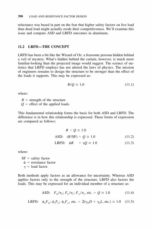
390 LOAD AND RESISTANCE FACTOR DESIGN
reluctance was based in part on the fear that higher safety factors on live loadthan dead load might actually erode their competitiveness. We’ll examine thisissue and compare ASD and LRFD outcomes in aluminum.
11.2 LRFD—THE CONCEPT
LRFD has been a bit like the Wizard of Oz: a fearsome persona hidden behinda veil of mystery. What’s hidden behind the curtain, however, is much morefamiliar-looking than the projected image would suggest. The science of sta-tistics that LRFD employs has not altered the laws of physics. The missionof engineers remains to design the structure to be stronger than the effect ofthe loads it supports. This may be expressed as:
R /Q � 1.0 (11.1)
where:
R � strength of the structureQ � effect of the applied loads.
This fundamental relationship forms the basis for both ASD and LRFD. Thedifference is in how this relationship is expressed. These forms of expressionare compared as follows:
R Q � 1.0
ASD: (R /SF) Q � 1.0 (11.2)
LRFD: R �Q � 1.0 (11.3)
where:
SF � safety factor � resistance factor� � load factor.
Both methods apply factors as an allowance for uncertainty. Whereas ASDapplies factors only to the strength of the structure, LRFD also factors theloads. This may be expressed for an individual member of a structure as:
ASD: F /n ; F /n ; F /n , etc. Q � 1.0 (11.4)tu u ty y cy y
LRFD: F ; F ; F , etc. �(� D � � L, etc.) � 1.0 (11.5)u tu y ty y cy D L
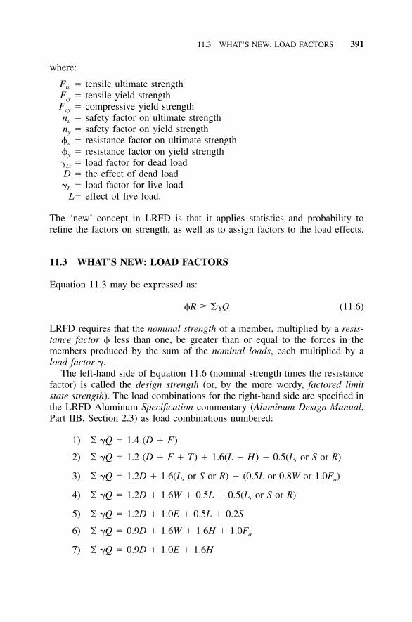
11.3 WHAT’S NEW: LOAD FACTORS 391
where:
Ftu � tensile ultimate strengthFty � tensile yield strengthFcy � compressive yield strengthnu � safety factor on ultimate strengthny � safety factor on yield strengthu � resistance factor on ultimate strengthy � resistance factor on yield strength�D � load factor for dead loadD � the effect of dead load�L � load factor for live load
L� effect of live load.
The ‘new’ concept in LRFD is that it applies statistics and probability torefine the factors on strength, as well as to assign factors to the load effects.
11.3 WHAT’S NEW: LOAD FACTORS
Equation 11.3 may be expressed as:
R � ��Q (11.6)
LRFD requires that the nominal strength of a member, multiplied by a resis-tance factor less than one, be greater than or equal to the forces in themembers produced by the sum of the nominal loads, each multiplied by aload factor �.
The left-hand side of Equation 11.6 (nominal strength times the resistancefactor) is called the design strength (or, by the more wordy, factored limitstate strength). The load combinations for the right-hand side are specified inthe LRFD Aluminum Specification commentary (Aluminum Design Manual,Part IIB, Section 2.3) as load combinations numbered:
1) � �Q � 1.4 (D � F)
2) � �Q � 1.2 (D � F � T) � 1.6(L � H) � 0.5(L or S or R)r
3) � �Q � 1.2D � 1.6(L or S or R) � (0.5L or 0.8W or 1.0F )r a
4) � �Q � 1.2D � 1.6W � 0.5L � 0.5(L or S or R)r
5) � �Q � 1.2D � 1.0E � 0.5L � 0.2S
6) � �Q � 0.9D � 1.6W � 1.6H � 1.0Fa
7) � �Q � 0.9D � 1.0E � 1.6H
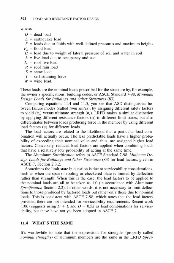
392 LOAD AND RESISTANCE FACTOR DESIGN
where:
D � dead loadE � earthquake loadF � loads due to fluids with well-defined pressures and maximum heights
Fa � flood loadH � load due to weight of lateral pressure of soil and water in soilL � live load due to occupancy and use
Lr � roof live loadR � roof rain loadS � snow loadT � self-straining force
W � wind load.
These loads are the nominal loads prescribed for the structure by, for example,the owner’s specifications, building codes, or ASCE Standard 7-98, MinimumDesign Loads for Buildings and Other Structures (83).
Comparing equations 11.4 and 11.5, you see that ASD distinguishes be-tween failure modes (called limit states), by assigning different safety factorsto yield (ny) versus ultimate strength (nu). LRFD makes a similar distinctionby applying different resistance factors () to different limit states, but alsodifferentiates between loads producing force in the member by using differentload factors (�) for different loads.
The load factors are related to the likelihood that a particular load com-bination will actually occur. The less predictable loads have a higher proba-bility of exceeding their nominal value and, thus, are assigned higher loadfactors. Conversely, reduced load factors are applied when combining loadsthat have a relatively low probability of acting at the same time.
The Aluminum Specification refers to ASCE Standard 7-98, Minimum De-sign Loads for Buildings and Other Structures (83) for load factors, given inASCE 7, Section 2.3.2.
Sometimes the limit state in question is due to serviceability considerations,such as when the span of roofing or checkered plate is limited by deflectionrather than strength. When this is the case, the load factors to be applied tothe nominal loads are all to be taken as 1.0 (in accordance with AluminumSpecification Section 2.2). In other words, it is not necessary to limit deflec-tions to those produced by factored loads but rather only those due to nominalloads. This is consistent with ASCE 7-98, which notes that the load factorsprovided there are not intended for serviceability requirements. Recent work(106) suggests using D � L and D � 0.5S as load combinations for service-ability, but these have not yet been adopted in ASCE 7.
11.4 WHAT’S THE SAME
It’s worthwhile to note that the expressions for strengths (properly callednominal strengths) of aluminum members are the same in the LRFD Speci-
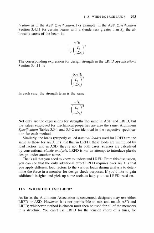
11.5 WHEN DO I USE LRFD? 393
fication as in the ASD Specification. For example, in the ASD SpecificationSection 3.4.11 for certain beams with a slenderness greater than S2, the al-lowable stress of the beam is:
2� E2Lbn � �y 1.2ry
The corresponding expression for design strength in the LRFD SpecificationsSection 3.4.11 is:
2 � Eb2Lb� �1.2ry
In each case, the strength term is the same:
2� E2Lb� �1.2ry
Not only are the expressions for strengths the same in ASD and LRFD, butthe values employed for mechanical properties are also the same. AluminumSpecification Tables 3.3-1 and 3.3-2 are identical in the respective specifica-tion for each method.
Similarly, the loads (properly called nominal loads) used for LRFD are thesame as those for ASD. It’s just that in LRFD, these loads are multiplied byload factors, and in ASD, they’re not. In both cases, stresses are calculatedby conventional elastic analysis. LRFD is not an attempt to introduce plasticdesign under another name.
That’s all that you need to know to understand LRFD. From this discussion,you can see that the only additional effort LRFD requires over ASD is thatyou apply different load factors to the various loads during analysis to deter-mine the force in a member for design check purposes. If you’d like to gainadditional insights and pick up some tools to help you use LRFD, read on.
11.5 WHEN DO I USE LRFD?
As far as the Aluminum Association is concerned, designers may use eitherLRFD or ASD. However, it is not permissible to mix and match ASD andLRFD; whichever method is chosen must then be used for all of the membersin a structure. You can’t use LRFD for the tension chord of a truss, for
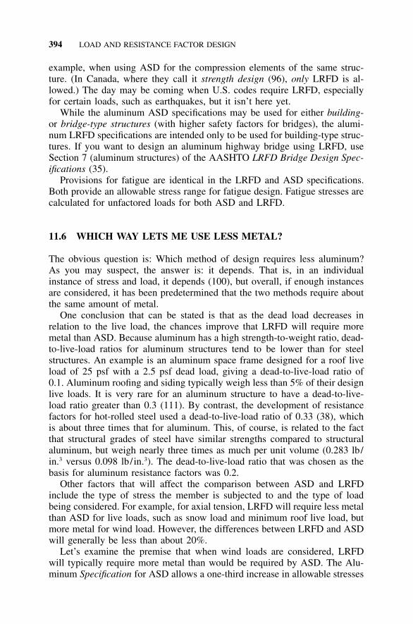
394 LOAD AND RESISTANCE FACTOR DESIGN
example, when using ASD for the compression elements of the same struc-ture. (In Canada, where they call it strength design (96), only LRFD is al-lowed.) The day may be coming when U.S. codes require LRFD, especiallyfor certain loads, such as earthquakes, but it isn’t here yet.
While the aluminum ASD specifications may be used for either building-or bridge-type structures (with higher safety factors for bridges), the alumi-num LRFD specifications are intended only to be used for building-type struc-tures. If you want to design an aluminum highway bridge using LRFD, useSection 7 (aluminum structures) of the AASHTO LRFD Bridge Design Spec-ifications (35).
Provisions for fatigue are identical in the LRFD and ASD specifications.Both provide an allowable stress range for fatigue design. Fatigue stresses arecalculated for unfactored loads for both ASD and LRFD.
11.6 WHICH WAY LETS ME USE LESS METAL?
The obvious question is: Which method of design requires less aluminum?As you may suspect, the answer is: it depends. That is, in an individualinstance of stress and load, it depends (100), but overall, if enough instancesare considered, it has been predetermined that the two methods require aboutthe same amount of metal.
One conclusion that can be stated is that as the dead load decreases inrelation to the live load, the chances improve that LRFD will require moremetal than ASD. Because aluminum has a high strength-to-weight ratio, dead-to-live-load ratios for aluminum structures tend to be lower than for steelstructures. An example is an aluminum space frame designed for a roof liveload of 25 psf with a 2.5 psf dead load, giving a dead-to-live-load ratio of0.1. Aluminum roofing and siding typically weigh less than 5% of their designlive loads. It is very rare for an aluminum structure to have a dead-to-live-load ratio greater than 0.3 (111). By contrast, the development of resistancefactors for hot-rolled steel used a dead-to-live-load ratio of 0.33 (38), whichis about three times that for aluminum. This, of course, is related to the factthat structural grades of steel have similar strengths compared to structuralaluminum, but weigh nearly three times as much per unit volume (0.283 lb/in.3 versus 0.098 lb/in.3). The dead-to-live-load ratio that was chosen as thebasis for aluminum resistance factors was 0.2.
Other factors that will affect the comparison between ASD and LRFDinclude the type of stress the member is subjected to and the type of loadbeing considered. For example, for axial tension, LRFD will require less metalthan ASD for live loads, such as snow load and minimum roof live load, butmore metal for wind load. However, the differences between LRFD and ASDwill generally be less than about 20%.
Let’s examine the premise that when wind loads are considered, LRFDwill typically require more metal than would be required by ASD. The Alu-minum Specification for ASD allows a one-third increase in allowable stresses
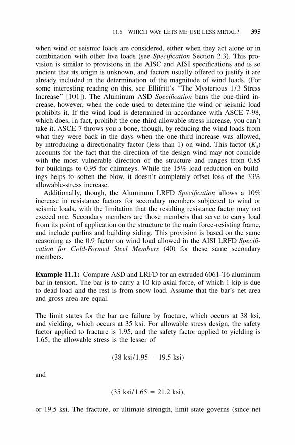
11.6 WHICH WAY LETS ME USE LESS METAL? 395
when wind or seismic loads are considered, either when they act alone or incombination with other live loads (see Specification Section 2.3). This pro-vision is similar to provisions in the AISC and AISI specifications and is soancient that its origin is unknown, and factors usually offered to justify it arealready included in the determination of the magnitude of wind loads. (Forsome interesting reading on this, see Ellifritt’s ‘‘The Mysterious 1/3 StressIncrease’’ [101]). The Aluminum ASD Specification bans the one-third in-crease, however, when the code used to determine the wind or seismic loadprohibits it. If the wind load is determined in accordance with ASCE 7-98,which does, in fact, prohibit the one-third allowable stress increase, you can’ttake it. ASCE 7 throws you a bone, though, by reducing the wind loads fromwhat they were back in the days when the one-third increase was allowed,by introducing a directionality factor (less than 1) on wind. This factor (Kd)accounts for the fact that the direction of the design wind may not coincidewith the most vulnerable direction of the structure and ranges from 0.85for buildings to 0.95 for chimneys. While the 15% load reduction on build-ings helps to soften the blow, it doesn’t completely offset loss of the 33%allowable-stress increase.
Additionally, though, the Aluminum LRFD Specification allows a 10%increase in resistance factors for secondary members subjected to wind orseismic loads, with the limitation that the resulting resistance factor may notexceed one. Secondary members are those members that serve to carry loadfrom its point of application on the structure to the main force-resisting frame,and include purlins and building siding. This provision is based on the samereasoning as the 0.9 factor on wind load allowed in the AISI LRFD Specifi-cation for Cold-Formed Steel Members (40) for these same secondarymembers.
Example 11.1: Compare ASD and LRFD for an extruded 6061-T6 aluminumbar in tension. The bar is to carry a 10 kip axial force, of which 1 kip is dueto dead load and the rest is from snow load. Assume that the bar’s net areaand gross area are equal.
The limit states for the bar are failure by fracture, which occurs at 38 ksi,and yielding, which occurs at 35 ksi. For allowable stress design, the safetyfactor applied to fracture is 1.95, and the safety factor applied to yielding is1.65; the allowable stress is the lesser of
(38 ksi/1.95 � 19.5 ksi)
and
(35 ksi/1.65 � 21.2 ksi),
or 19.5 ksi. The fracture, or ultimate strength, limit state governs (since net
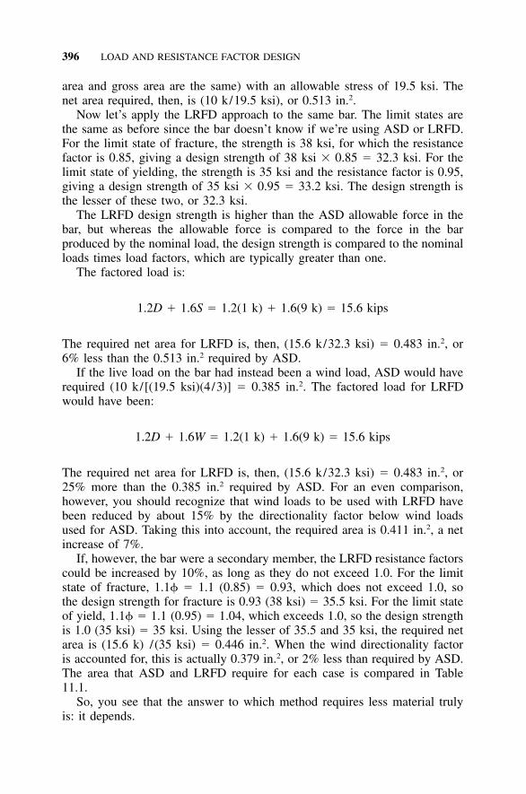
396 LOAD AND RESISTANCE FACTOR DESIGN
area and gross area are the same) with an allowable stress of 19.5 ksi. Thenet area required, then, is (10 k/19.5 ksi), or 0.513 in.2.
Now let’s apply the LRFD approach to the same bar. The limit states arethe same as before since the bar doesn’t know if we’re using ASD or LRFD.For the limit state of fracture, the strength is 38 ksi, for which the resistancefactor is 0.85, giving a design strength of 38 ksi � 0.85 � 32.3 ksi. For thelimit state of yielding, the strength is 35 ksi and the resistance factor is 0.95,giving a design strength of 35 ksi � 0.95 � 33.2 ksi. The design strength isthe lesser of these two, or 32.3 ksi.
The LRFD design strength is higher than the ASD allowable force in thebar, but whereas the allowable force is compared to the force in the barproduced by the nominal load, the design strength is compared to the nominalloads times load factors, which are typically greater than one.
The factored load is:
1.2D � 1.6S � 1.2(1 k) � 1.6(9 k) � 15.6 kips
The required net area for LRFD is, then, (15.6 k/32.3 ksi) � 0.483 in.2, or6% less than the 0.513 in.2 required by ASD.
If the live load on the bar had instead been a wind load, ASD would haverequired (10 k/[(19.5 ksi)(4/3)] � 0.385 in.2. The factored load for LRFDwould have been:
1.2D � 1.6W � 1.2(1 k) � 1.6(9 k) � 15.6 kips
The required net area for LRFD is, then, (15.6 k/32.3 ksi) � 0.483 in.2, or25% more than the 0.385 in.2 required by ASD. For an even comparison,however, you should recognize that wind loads to be used with LRFD havebeen reduced by about 15% by the directionality factor below wind loadsused for ASD. Taking this into account, the required area is 0.411 in.2, a netincrease of 7%.
If, however, the bar were a secondary member, the LRFD resistance factorscould be increased by 10%, as long as they do not exceed 1.0. For the limitstate of fracture, 1.1 � 1.1 (0.85) � 0.93, which does not exceed 1.0, sothe design strength for fracture is 0.93 (38 ksi) � 35.5 ksi. For the limit stateof yield, 1.1 � 1.1 (0.95) � 1.04, which exceeds 1.0, so the design strengthis 1.0 (35 ksi) � 35 ksi. Using the lesser of 35.5 and 35 ksi, the required netarea is (15.6 k) /(35 ksi) � 0.446 in.2. When the wind directionality factoris accounted for, this is actually 0.379 in.2, or 2% less than required by ASD.The area that ASD and LRFD require for each case is compared in Table11.1.
So, you see that the answer to which method requires less material trulyis: it depends.
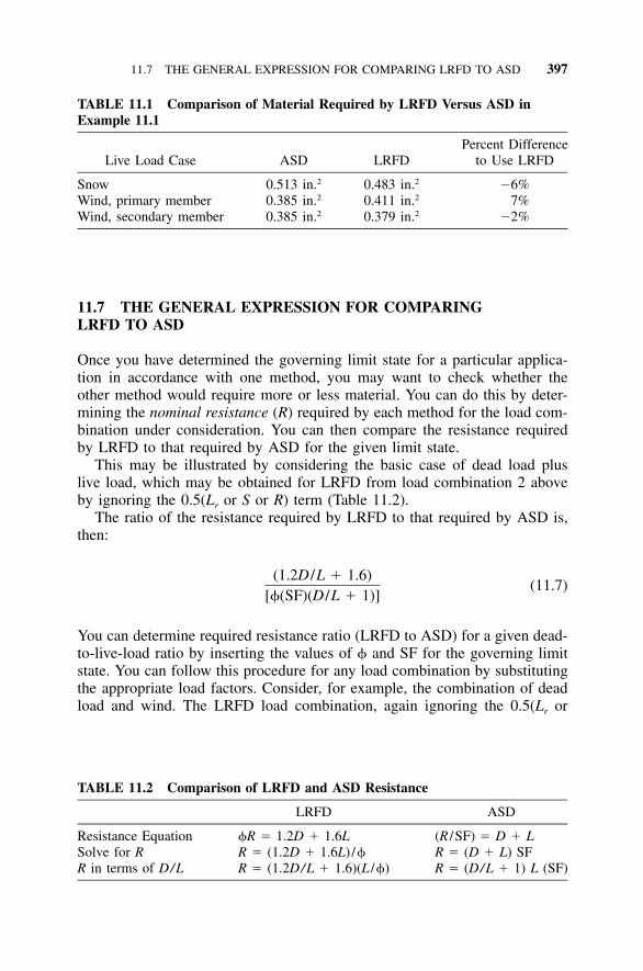
11.7 THE GENERAL EXPRESSION FOR COMPARING LRFD TO ASD 397
TABLE 11.1 Comparison of Material Required by LRFD Versus ASD inExample 11.1
Live Load Case ASD LRFDPercent Difference
to Use LRFD
Snow 0.513 in.2 0.483 in.2 �6%Wind, primary member 0.385 in.2 0.411 in.2 7%Wind, secondary member 0.385 in.2 0.379 in.2 �2%
TABLE 11.2 Comparison of LRFD and ASD Resistance
LRFD ASD
Resistance Equation R � 1.2D � 1.6L (R /SF) � D � LSolve for R R � (1.2D � 1.6L) / R � (D � L) SFR in terms of D/L R � (1.2D/L � 1.6)(L /) R � (D/L � 1) L (SF)
11.7 THE GENERAL EXPRESSION FOR COMPARINGLRFD TO ASD
Once you have determined the governing limit state for a particular applica-tion in accordance with one method, you may want to check whether theother method would require more or less material. You can do this by deter-mining the nominal resistance (R) required by each method for the load com-bination under consideration. You can then compare the resistance requiredby LRFD to that required by ASD for the given limit state.
This may be illustrated by considering the basic case of dead load pluslive load, which may be obtained for LRFD from load combination 2 aboveby ignoring the 0.5(Lr or S or R) term (Table 11.2).
The ratio of the resistance required by LRFD to that required by ASD is,then:
(1.2D /L � 1.6)(11.7)
[(SF)(D /L � 1)]
You can determine required resistance ratio (LRFD to ASD) for a given dead-to-live-load ratio by inserting the values of and SF for the governing limitstate. You can follow this procedure for any load combination by substitutingthe appropriate load factors. Consider, for example, the combination of deadload and wind. The LRFD load combination, again ignoring the 0.5(Lr or
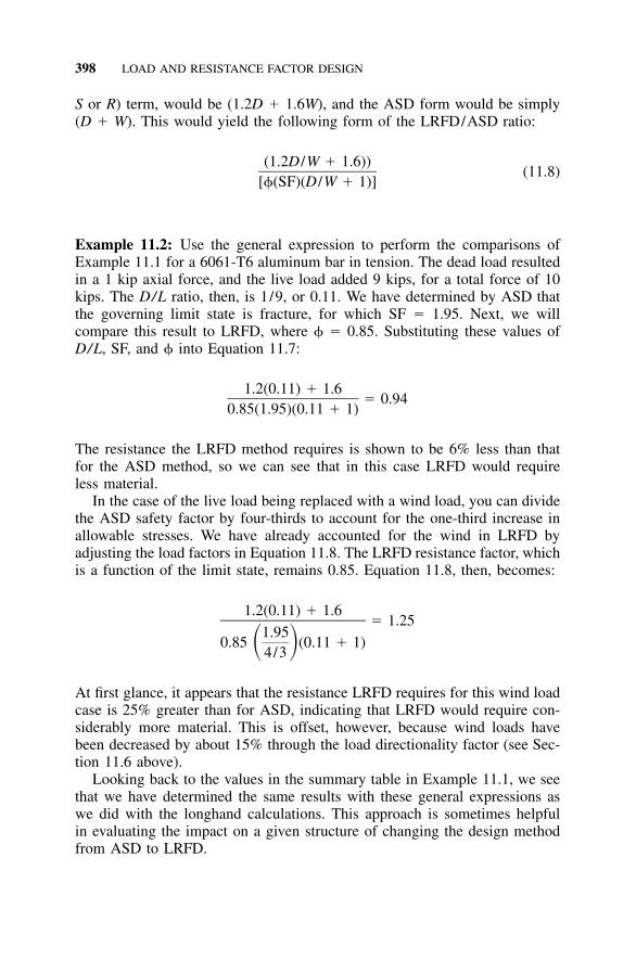
398 LOAD AND RESISTANCE FACTOR DESIGN
S or R) term, would be (1.2D � 1.6W), and the ASD form would be simply(D � W). This would yield the following form of the LRFD/ASD ratio:
(1.2D /W � 1.6))(11.8)
[(SF)(D /W � 1)]
Example 11.2: Use the general expression to perform the comparisons ofExample 11.1 for a 6061-T6 aluminum bar in tension. The dead load resultedin a 1 kip axial force, and the live load added 9 kips, for a total force of 10kips. The D/L ratio, then, is 1/9, or 0.11. We have determined by ASD thatthe governing limit state is fracture, for which SF � 1.95. Next, we willcompare this result to LRFD, where � 0.85. Substituting these values ofD/L, SF, and into Equation 11.7:
1.2(0.11) � 1.6� 0.94
0.85(1.95)(0.11 � 1)
The resistance the LRFD method requires is shown to be 6% less than thatfor the ASD method, so we can see that in this case LRFD would requireless material.
In the case of the live load being replaced with a wind load, you can dividethe ASD safety factor by four-thirds to account for the one-third increase inallowable stresses. We have already accounted for the wind in LRFD byadjusting the load factors in Equation 11.8. The LRFD resistance factor, whichis a function of the limit state, remains 0.85. Equation 11.8, then, becomes:
1.2(0.11) � 1.6� 1.25
1.950.85 (0.11 � 1)� �4/3
At first glance, it appears that the resistance LRFD requires for this wind loadcase is 25% greater than for ASD, indicating that LRFD would require con-siderably more material. This is offset, however, because wind loads havebeen decreased by about 15% through the load directionality factor (see Sec-tion 11.6 above).
Looking back to the values in the summary table in Example 11.1, we seethat we have determined the same results with these general expressions aswe did with the longhand calculations. This approach is sometimes helpfulin evaluating the impact on a given structure of changing the design methodfrom ASD to LRFD.
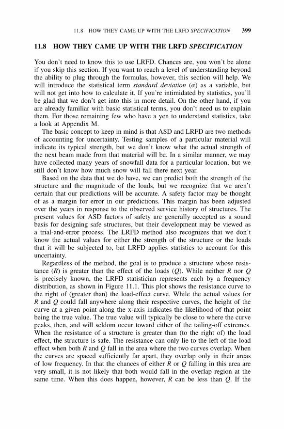
11.8 HOW THEY CAME UP WITH THE LRFD SPECIFICATION 399
11.8 HOW THEY CAME UP WITH THE LRFD SPECIFICATION
You don’t need to know this to use LRFD. Chances are, you won’t be aloneif you skip this section. If you want to reach a level of understanding beyondthe ability to plug through the formulas, however, this section will help. Wewill introduce the statistical term standard deviation (�) as a variable, butwill not get into how to calculate it. If you’re intimidated by statistics, you’llbe glad that we don’t get into this in more detail. On the other hand, if youare already familiar with basic statistical terms, you don’t need us to explainthem. For those remaining few who have a yen to understand statistics, takea look at Appendix M.
The basic concept to keep in mind is that ASD and LRFD are two methodsof accounting for uncertainty. Testing samples of a particular material willindicate its typical strength, but we don’t know what the actual strength ofthe next beam made from that material will be. In a similar manner, we mayhave collected many years of snowfall data for a particular location, but westill don’t know how much snow will fall there next year.
Based on the data that we do have, we can predict both the strength of thestructure and the magnitude of the loads, but we recognize that we aren’tcertain that our predictions will be accurate. A safety factor may be thoughtof as a margin for error in our predictions. This margin has been adjustedover the years in response to the observed service history of structures. Thepresent values for ASD factors of safety are generally accepted as a soundbasis for designing safe structures, but their development may be viewed asa trial-and-error process. The LRFD method also recognizes that we don’tknow the actual values for either the strength of the structure or the loadsthat it will be subjected to, but LRFD applies statistics to account for thisuncertainty.
Regardless of the method, the goal is to produce a structure whose resis-tance (R) is greater than the effect of the loads (Q). While neither R nor Qis precisely known, the LRFD statistician represents each by a frequencydistribution, as shown in Figure 11.1. This plot shows the resistance curve tothe right of (greater than) the load-effect curve. While the actual values forR and Q could fall anywhere along their respective curves, the height of thecurve at a given point along the x-axis indicates the likelihood of that pointbeing the true value. The true value will typically be close to where the curvepeaks, then, and will seldom occur toward either of the tailing-off extremes.When the resistance of a structure is greater than (to the right of) the loadeffect, the structure is safe. The resistance can only lie to the left of the loadeffect when both R and Q fall in the area where the two curves overlap. Whenthe curves are spaced sufficiently far apart, they overlap only in their areasof low frequency. In that the chances of either R or Q falling in this area arevery small, it is not likely that both would fall in the overlap region at thesame time. When this does happen, however, R can be less than Q. If the
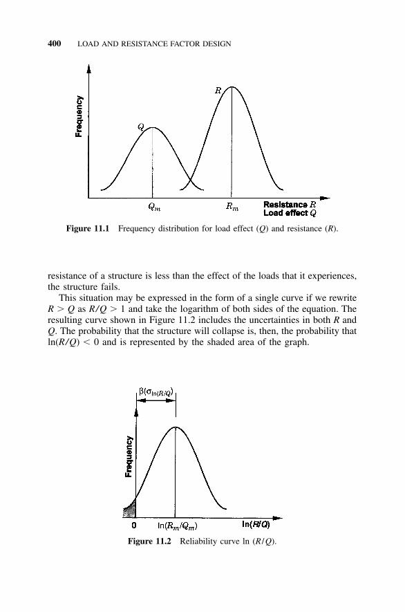
400 LOAD AND RESISTANCE FACTOR DESIGN
Figure 11.1 Frequency distribution for load effect (Q) and resistance (R).
Figure 11.2 Reliability curve ln (R /Q).
resistance of a structure is less than the effect of the loads that it experiences,the structure fails.
This situation may be expressed in the form of a single curve if we rewriteR � Q as R/Q � 1 and take the logarithm of both sides of the equation. Theresulting curve shown in Figure 11.2 includes the uncertainties in both R andQ. The probability that the structure will collapse is, then, the probability thatln(R/Q) � 0 and is represented by the shaded area of the graph.
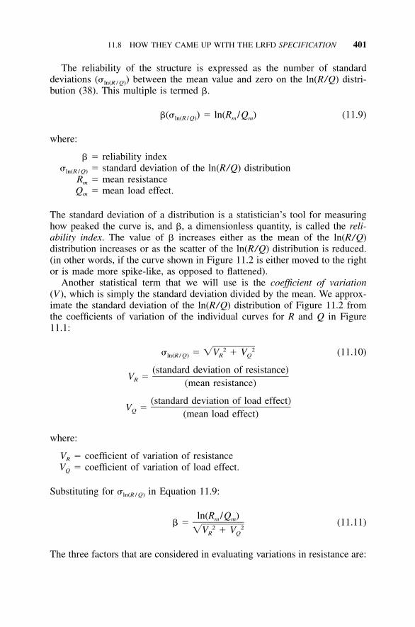
11.8 HOW THEY CAME UP WITH THE LRFD SPECIFICATION 401
The reliability of the structure is expressed as the number of standarddeviations (�ln(R / Q)) between the mean value and zero on the ln(R/Q) distri-bution (38). This multiple is termed �.
�(� ) � ln(R /Q ) (11.9)ln(R / Q) m m
where:
� � reliability index�ln(R / Q) � standard deviation of the ln(R/Q) distribution
Rm � mean resistanceQm � mean load effect.
The standard deviation of a distribution is a statistician’s tool for measuringhow peaked the curve is, and �, a dimensionless quantity, is called the reli-ability index. The value of � increases either as the mean of the ln(R/Q)distribution increases or as the scatter of the ln(R/Q) distribution is reduced.(in other words, if the curve shown in Figure 11.2 is either moved to the rightor is made more spike-like, as opposed to flattened).
Another statistical term that we will use is the coefficient of variation(V), which is simply the standard deviation divided by the mean. We approx-imate the standard deviation of the ln(R/Q) distribution of Figure 11.2 fromthe coefficients of variation of the individual curves for R and Q in Figure11.1:
2 2� � �V � V (11.10)ln(R / Q) R Q
(standard deviation of resistance)V �R (mean resistance)
(standard deviation of load effect)V �Q (mean load effect)
where:
VR � coefficient of variation of resistanceVQ � coefficient of variation of load effect.
Substituting for �ln(R / Q) in Equation 11.9:
ln(R /Q )m m� � (11.11)2 2�V � VR Q
The three factors that are considered in evaluating variations in resistance are:
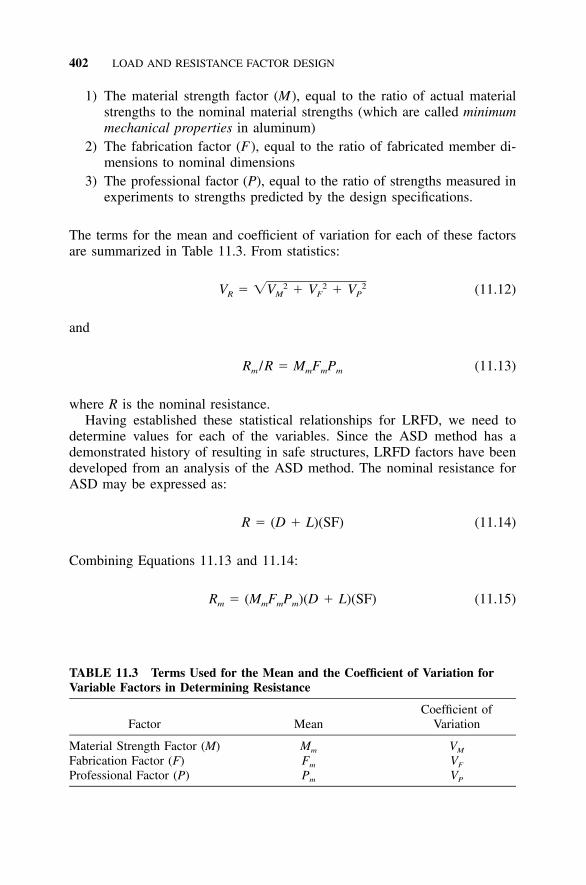
402 LOAD AND RESISTANCE FACTOR DESIGN
TABLE 11.3 Terms Used for the Mean and the Coefficient of Variation forVariable Factors in Determining Resistance
Factor MeanCoefficient of
Variation
Material Strength Factor (M) Mm VM
Fabrication Factor (F) Fm VF
Professional Factor (P) Pm VP
1) The material strength factor (M), equal to the ratio of actual materialstrengths to the nominal material strengths (which are called minimummechanical properties in aluminum)
2) The fabrication factor (F), equal to the ratio of fabricated member di-mensions to nominal dimensions
3) The professional factor (P), equal to the ratio of strengths measured inexperiments to strengths predicted by the design specifications.
The terms for the mean and coefficient of variation for each of these factorsare summarized in Table 11.3. From statistics:
2 2 2V � �V � V � V (11.12)R M F P
and
R /R � M F P (11.13)m m m m
where R is the nominal resistance.Having established these statistical relationships for LRFD, we need to
determine values for each of the variables. Since the ASD method has ademonstrated history of resulting in safe structures, LRFD factors have beendeveloped from an analysis of the ASD method. The nominal resistance forASD may be expressed as:
R � (D � L)(SF) (11.14)
Combining Equations 11.13 and 11.14:
R � (M F P )(D � L)(SF) (11.15)m m m m
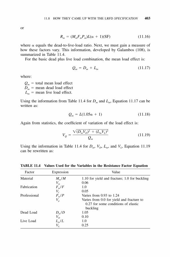
11.8 HOW THEY CAME UP WITH THE LRFD SPECIFICATION 403
TABLE 11.4 Values Used for the Variables in the Resistance Factor Equation
Factor Expression Value
Material Mm /MVm
1.10 for yield and fracture; 1.0 for buckling0.06
Fabrication Fm /FVf
1.00.05
Professional Pm /PVp
Varies from 0.93 to 1.24Varies from 0.0 for yield and fracture to
0.27 for some conditions of elasticbuckling
Dead Load Dm /DVD
1.050.10
Live Load Lm /LVL
1.00.25
or
R � (M F P )L(� � 1)(SF) (11.16)m m m m
where � equals the dead-to-live-load ratio. Next, we must gain a measure ofhow these factors vary. This information, developed by Galambos (108), issummarized in Table 11.4.
For the basic dead plus live load combination, the mean load effect is:
Q � D � L (11.17)m m m
where:
Qm � total mean load effectDm � mean dead load effectLm � mean live load effect.
Using the information from Table 11.4 for Dm and Lm, Equation 11.17 can bewritten as:
Q � L(1.05� � 1) (11.18)m
Again from statistics, the coefficient of variation of the load effect is:
2 2�(D V ) � (L V )m D m LV � (11.19)Q Qm
Using the information in Table 11.4 for Dm, VD, Lm, and VL, Equation 11.19can be rewritten as:
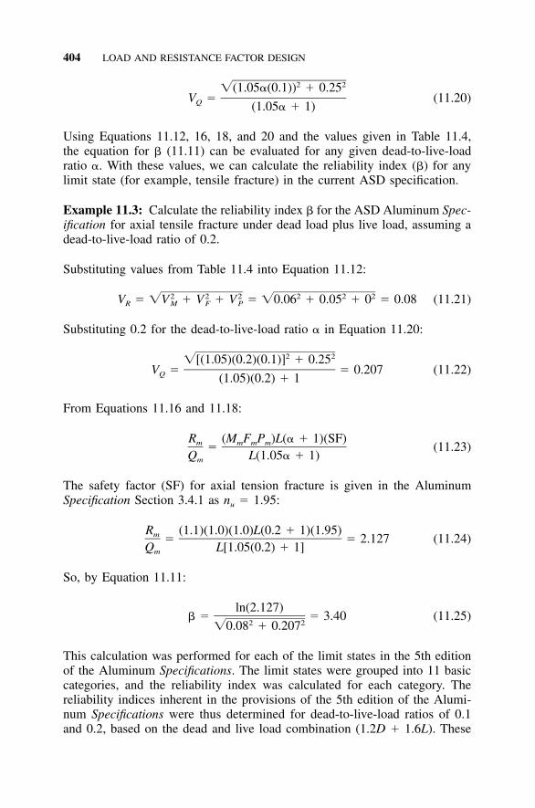
404 LOAD AND RESISTANCE FACTOR DESIGN
2 2�(1.05�(0.1)) � 0.25V � (11.20)Q (1.05� � 1)
Using Equations 11.12, 16, 18, and 20 and the values given in Table 11.4,the equation for � (11.11) can be evaluated for any given dead-to-live-loadratio �. With these values, we can calculate the reliability index (�) for anylimit state (for example, tensile fracture) in the current ASD specification.
Example 11.3: Calculate the reliability index � for the ASD Aluminum Spec-ification for axial tensile fracture under dead load plus live load, assuming adead-to-live-load ratio of 0.2.
Substituting values from Table 11.4 into Equation 11.12:
2 2 2 2 2 2V � �V � V � V � �0.06 � 0.05 � 0 � 0.08 (11.21)R M F P
Substituting 0.2 for the dead-to-live-load ratio � in Equation 11.20:
2 2�[(1.05)(0.2)(0.1)] � 0.25V � � 0.207 (11.22)Q (1.05)(0.2) � 1
From Equations 11.16 and 11.18:
R (M F P )L(� � 1)(SF)m m m m� (11.23)Q L(1.05� � 1)m
The safety factor (SF) for axial tension fracture is given in the AluminumSpecification Section 3.4.1 as nu � 1.95:
R (1.1)(1.0)(1.0)L(0.2 � 1)(1.95)m � � 2.127 (11.24)Q L[1.05(0.2) � 1]m
So, by Equation 11.11:
ln(2.127)� � � 3.40 (11.25)
2 2�0.08 � 0.207
This calculation was performed for each of the limit states in the 5th editionof the Aluminum Specifications. The limit states were grouped into 11 basiccategories, and the reliability index was calculated for each category. Thereliability indices inherent in the provisions of the 5th edition of the Alumi-num Specifications were thus determined for dead-to-live-load ratios of 0.1and 0.2, based on the dead and live load combination (1.2D � 1.6L). These
11.9 HOW DO I ACTUALLY START USING LRFD? 405
calculations thereby took into account the ASD factors of safety and thematerial, fabrication, professional, and load effect factors described above.The resulting reliability indices ranged from 1.65 to 3.16 for a dead-to-live-load ratio of 0.1, and 1.75 to 3.40 for a D /L ratio of 0.2.
Based on these results, target reliability indices of 2.5 for yielding andbuckling limit states and 3.0 for fracture limit states were judged to be rep-resentative of current aluminum practice and selected to give similar (butmore uniform) reliabilities for the LRFD Specification. Equation 11.9 wasreformulated with �T set equal to the appropriate target (2.5 or 3.0, dependingon the limit state in question) and the nominal resistance expressed as:
R � (1.2D � 1.6L) / (11.26)
The only unknown variable in the equation was , which is solved for as:
(R /R)(1.2� � 1.6)m ��1 2 2(1.05� � 1)ln (� �V � V )T R Q
where �T � the target reliability index.The resistance factors () were thus calculated for each of the 11 categories
of limit states, rounded to the nearest 0.05, and used for the LRFD Specifi-cation. This process of developing values for LRFD from current ASD prac-tice is referred to as calibrating the resistance factors.
Reliability indices of 2.0 and 2.5 were chosen for secondary memberssubjected to wind or seismic loads, which is achieved by multiplying resis-tance factors by 1.1 for these cases, as noted previously in this chapter.
If you followed this somewhat tortuous process, you’ll see that the basicpremise used in setting up LRFD is that the overall reliability of structuresdesigned to ASD specifications has been acceptable. So why tinker withASD? Because the reliability in ASD specifications is not uniform for thevarious failure modes, and the LRFD approach can be more so. Some peoplecare about that.
11.9 HOW DO I ACTUALLY START USING LRFD?
It’s evident that quite a lot of effort has gone into the development of LRFD.While the development of the LRFD method may be complicated, the use ofit in practice need not be any more difficult than that of ASD. The designsteps may be summarized as:
1) Analyze the structure in the same manner as with ASD, but factor theapplied loads.
2) Perform all the design checks that ASD requires, but use the LRFDdesign stresses rather than the ASD allowable stresses.
406 LOAD AND RESISTANCE FACTOR DESIGN
The Aluminum Design Manual, however, while including handy allowablestress tables for ASD, offers no corresponding design stress tables for LRFD.To remedy this, Appendix I contains design stress tables for some commonaluminum alloys, similar to the allowable stress tables in Aluminum DesignManual, Part VII, Design Aids, Tables 2-2 through 2-23. We have also pro-vided the LRFD design stresses for local buckling of Aluminum Associationstandard channels and I-beams in Appendix E. With these tools, LRFD canbe undertaken just as readily as ASD.
11.10 THE FUTURE OF THE ASD AND LRFD ALUMINUMSPECIFICATIONS
The AISC stopped updating the ASD Steel Specification after the 9th editionwas issued in 1989 while continuing to update the LRFD specification. It nowappears the AISC is moving toward a unified specification allowing both ASDand LRFD, to be published around 2005. The Aluminum Association, how-ever, has chosen a different approach, and plans to continue to present boththe ASD and LRFD specifications in the Aluminum Design Manual.
While this might seem to represent a fundamental difference in philosophy,it isn’t. The AISC Specification for Structural Steel Buildings is, as its titlesays, exclusively for designing buildings, for which load factors have beendeveloped and which are designed by structural engineers almost exclusively.The ASD Aluminum Specification, on the other hand, is used to design allsorts of structural components in addition to building structures, such as pip-ing, crane hoists, automotive parts, and concrete forms, for which load factorshaven’t been developed. These components are often designed by mechanicalengineers who never heard of LRFD and were taught by professors whoprobably never will. This isn’t too surprising, considering that dead loads areusually negligible for such components and a single overriding service loadis often the sole criterion for their design. For these uses, an ASD AluminumSpecification will be both necessary and useful for the foreseeable future.Although it may have that effect, maintenance of the ASD Aluminum Spec-ification is not intended to discourage transition to LRFD for buildingstructures.
Maintenance of the parallel ASD and LRFD specifications, however, doesresult in one anomaly. In order to keep the specifications as parallel as pos-sible, the LRFD Specification has been written so that the strength of membersis expressed in terms of stress (the ‘‘factored limit state stress’’), rather thanin terms of force and moment (the ‘‘design strength’’), the way the steel andCanadian and European aluminum design specifications are expressed.
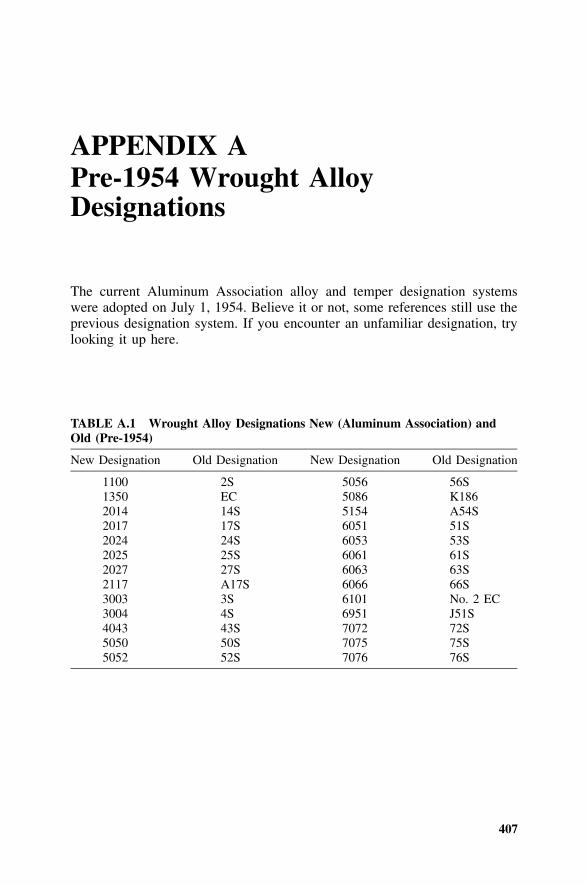
407
APPENDIX APre-1954 Wrought AlloyDesignations
The current Aluminum Association alloy and temper designation systemswere adopted on July 1, 1954. Believe it or not, some references still use theprevious designation system. If you encounter an unfamiliar designation, trylooking it up here.
TABLE A.1 Wrought Alloy Designations New (Aluminum Association) andOld (Pre-1954)
New Designation Old Designation New Designation Old Designation
1100 2S 5056 56S1350 EC 5086 K1862014 14S 5154 A54S2017 17S 6051 51S2024 24S 6053 53S2025 25S 6061 61S2027 27S 6063 63S2117 A17S 6066 66S3003 3S 6101 No. 2 EC3004 4S 6951 J51S4043 43S 7072 72S5050 50S 7075 75S5052 52S 7076 76S
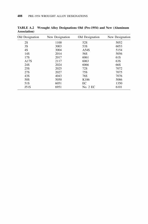
408 PRE-1954 WROUGHT ALLOY DESIGNATIONS
TABLE A.2 Wrought Alloy Designations Old (Pre-1954) and New (AluminumAssociation)
Old Designation New Designation Old Designation New Designation
2S 1100 52S 50523S 3003 53S 60534S 3004 A54S 515414S 2014 56S 505617S 2017 6061 61SA17S 2117 6063 63S24S 2024 6066 66S25S 2025 72S 707227S 2027 75S 707543S 4043 76S 707650S 5050 K186 508651S 6051 EC 1350J51S 6951 No. 2 EC 6101

409
APPENDIX BSection Properties of CommonAluminum Shapes
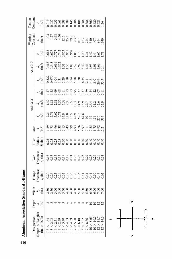
410
Alu
min
umA
ssoc
iati
onSt
anda
rdI-
Bea
ms
Des
igna
tion
Dep
thW
idth
Flan
geW
ebFi
llet
Are
aA
xis
X-X
Axi
sY
-YW
arpi
ngC
onst
ant
Tors
ion
Con
stan
t(D
epth
�W
eigh
t)(i
n.�
lb/f
t)d
(in.
)b f (in.
)T
hick
ness
t f(i
n.)
Thi
ckne
sst w
(in.
)R
adiu
sR
(in.
)A
(in.
2)
I x(i
n.4)
S x(i
n.3)
r x (in.
)I y
(in.
4)
S y(i
n.3)
r y (in.
)C
w
(in.
6)
J(i
n.4)
I3
�1.
643
2.50
0.20
0.13
0.25
1.39
2.24
1.49
1.27
0.52
20.
418
0.61
31.
020.
019
I3
�2.
033
2.50
0.26
0.15
0.25
1.73
2.71
1.81
1.25
0.67
90.
543
0.62
71.
270.
037
I4
�2.
314
3.00
0.23
0.15
0.25
1.96
5.62
2.81
1.69
1.04
0.69
10.
727
3.68
0.03
3I
4�
2.79
43.
000.
290.
170.
252.
386.
713.
361.
681.
310.
872
0.74
24.
500.
061
I5
�3.
705
3.50
0.32
0.19
0.30
3.15
13.9
5.58
2.11
2.29
1.31
0.85
312
.50.
098
I6
�4.
036
4.00
0.29
0.19
0.30
3.43
22.0
7.33
2.53
3.10
1.55
0.95
125
.30.
089
I6
�4.
696
4.00
0.35
0.21
0.30
3.99
25.5
8.50
2.53
3.74
1.87
0.96
829
.80.
145
I7
�5.
807
4.50
0.38
0.23
0.30
4.93
42.9
12.3
2.95
5.78
2.57
1.08
63.3
0.20
6I
8�
6.18
85.
000.
350.
230.
305.
2659
.714
.93.
377.
302.
921.
1810
70.
188
I8
�7.
028
5.00
0.41
0.25
0.30
5.97
67.8
16.9
3.37
8.55
3.42
1.20
123
0.28
6I
9�
8.36
95.
500.
440.
270.
307.
1110
222
.73.
7912
.24.
441.
3122
40.
386
I10
�8.
6510
6.00
0.41
0.25
0.40
7.35
132
26.4
4.24
14.8
4.93
1.42
340
0.36
0I
10�
10.3
106.
000.
500.
290.
408.
7515
631
.24.
2218
.06.
011.
4440
70.
620
I12
�11
.712
7.00
0.47
0.29
0.40
9.92
256
42.6
5.07
26.9
7.69
1.65
894
0.62
1I
12�
14.3
127.
000.
620.
310.
4012
.231
752
.95.
1135
.510
.11.
7111
491.
26
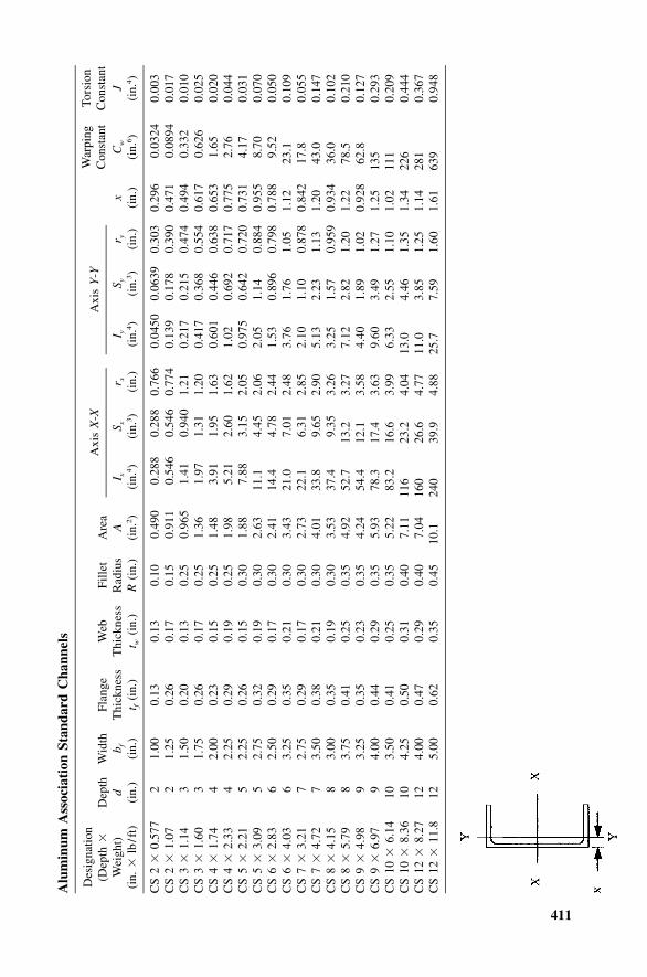
411
Alu
min
umA
ssoc
iati
onSt
anda
rdC
hann
els
Des
igna
tion
(Dep
th�
Dep
thW
idth
Flan
geW
ebFi
llet
Are
aA
xis
X-X
Axi
sY
-YW
arpi
ngC
onst
ant
Tors
ion
Con
stan
tW
eigh
t)(i
n.�
lb/f
t)d
(in.
)b f (in.
)T
hick
ness
t f(i
n.)
Thi
ckne
sst w
(in.
)R
adiu
sR
(in.
)A
(in.
2)
I x(i
n.4)
S x(i
n.3)
r x (in.
)I y
(in.
4)
S y(i
n.3)
r y (in.
)x
(in.
)C
w
(in.
6)
J(i
n.4)
CS
2�
0.57
72
1.00
0.13
0.13
0.10
0.49
00.
288
0.28
80.
766
0.04
500.
0639
0.30
30.
296
0.03
240.
003
CS
2�
1.07
21.
250.
260.
170.
150.
911
0.54
60.
546
0.77
40.
139
0.17
80.
390
0.47
10.
0894
0.01
7C
S3
�1.
143
1.50
0.20
0.13
0.25
0.96
51.
410.
940
1.21
0.21
70.
215
0.47
40.
494
0.33
20.
010
CS
3�
1.60
31.
750.
260.
170.
251.
361.
971.
311.
200.
417
0.36
80.
554
0.61
70.
626
0.02
5C
S4
�1.
744
2.00
0.23
0.15
0.25
1.48
3.91
1.95
1.63
0.60
10.
446
0.63
80.
653
1.65
0.02
0C
S4
�2.
334
2.25
0.29
0.19
0.25
1.98
5.21
2.60
1.62
1.02
0.69
20.
717
0.77
52.
760.
044
CS
5�
2.21
52.
250.
260.
150.
301.
887.
883.
152.
050.
975
0.64
20.
720
0.73
14.
170.
031
CS
5�
3.09
52.
750.
320.
190.
302.
6311
.14.
452.
062.
051.
140.
884
0.95
58.
700.
070
CS
6�
2.83
62.
500.
290.
170.
302.
4114
.44.
782.
441.
530.
896
0.79
80.
788
9.52
0.05
0C
S6
�4.
036
3.25
0.35
0.21
0.30
3.43
21.0
7.01
2.48
3.76
1.76
1.05
1.12
23.1
0.10
9C
S7
�3.
217
2.75
0.29
0.17
0.30
2.73
22.1
6.31
2.85
2.10
1.10
0.87
80.
842
17.8
0.05
5C
S7
�4.
727
3.50
0.38
0.21
0.30
4.01
33.8
9.65
2.90
5.13
2.23
1.13
1.20
43.0
0.14
7C
S8
�4.
158
3.00
0.35
0.19
0.30
3.53
37.4
9.35
3.26
3.25
1.57
0.95
90.
934
36.0
0.10
2C
S8
�5.
798
3.75
0.41
0.25
0.35
4.92
52.7
13.2
3.27
7.12
2.82
1.20
1.22
78.5
0.21
0C
S9
�4.
989
3.25
0.35
0.23
0.35
4.24
54.4
12.1
3.58
4.40
1.89
1.02
0.92
862
.80.
127
CS
9�
6.97
94.
000.
440.
290.
355.
9378
.317
.43.
639.
603.
491.
271.
2513
50.
293
CS
10�
6.14
103.
500.
410.
250.
355.
2283
.216
.63.
996.
332.
551.
101.
0211
10.
209
CS
10�
8.36
104.
250.
500.
310.
407.
1111
623
.24.
0413
.04.
461.
351.
3422
60.
444
CS
12�
8.27
124.
000.
470.
290.
407.
0416
026
.64.
7711
.03.
851.
251.
1428
10.
367
CS
12�
11.8
125.
000.
620.
350.
4510
.124
039
.94.
8825
.77.
591.
601.
6163
90.
948


413
APPENDIX CMinimum Mechanical Properties ofAluminum Alloys
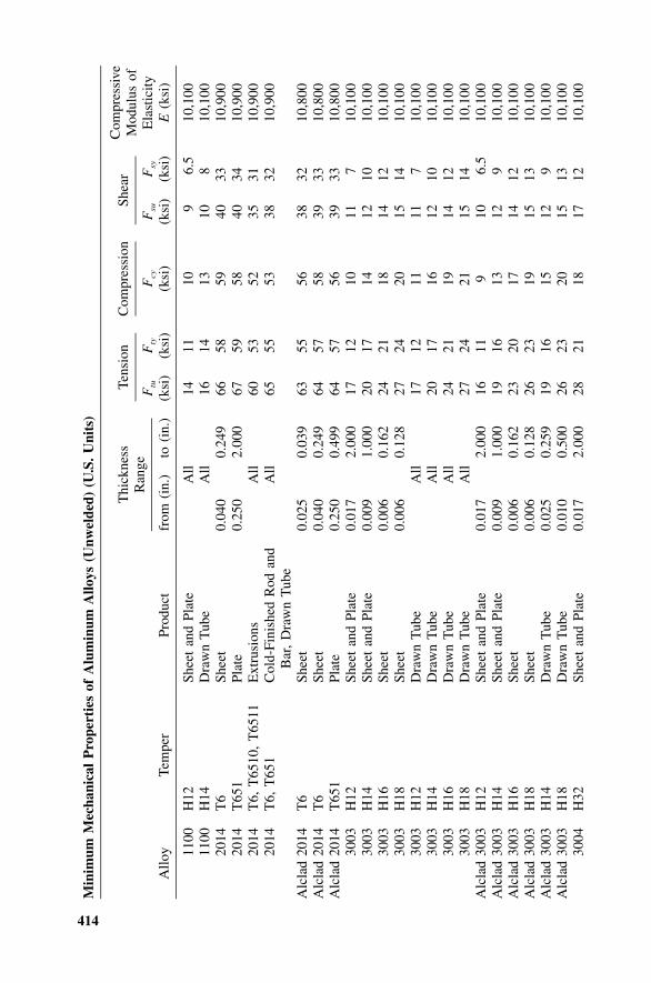
414
Min
imum
Mec
hani
cal
Pro
pert
ies
ofA
lum
inum
Allo
ys(U
nwel
ded)
(U.S
.U
nits
)
Allo
yTe
mpe
rPr
oduc
t
Thi
ckne
ssR
ange
from
(in.
)to
(in.
)
Tens
ion
Ftu
(ksi
)F
ty
(ksi
)
Com
pres
sion
Fcy
(ksi
)
Shea
r
Fsu
(ksi
)F
sy
(ksi
)
Com
pres
sive
Mod
ulus
ofE
last
icity
E(k
si)
1100
H12
Shee
tan
dPl
ate
All
1411
109
6.5
10,1
0011
00H
14D
raw
nT
ube
All
1614
1310
810
,100
2014
T6
Shee
t0.
040
0.24
966
5859
4033
10,9
0020
14T
651
Plat
e0.
250
2.00
067
5958
4034
10,9
0020
14T
6,T
6510
,T
6511
Ext
rusi
ons
All
6053
5235
3110
,900
2014
T6,
T65
1C
old-
Fini
shed
Rod
and
Bar
,D
raw
nT
ube
All
6555
5338
3210
,900
Alc
lad
2014
T6
Shee
t0.
025
0.03
963
5556
3832
10,8
00A
lcla
d20
14T
6Sh
eet
0.04
00.
249
6457
5839
3310
,800
Alc
lad
2014
T65
1Pl
ate
0.25
00.
499
6457
5639
3310
,800
3003
H12
Shee
tan
dPl
ate
0.01
72.
000
1712
1011
710
,100
3003
H14
Shee
tan
dPl
ate
0.00
91.
000
2017
1412
1010
,100
3003
H16
Shee
t0.
006
0.16
224
2118
1412
10,1
0030
03H
18Sh
eet
0.00
60.
128
2724
2015
1410
,100
3003
H12
Dra
wn
Tub
eA
ll17
1211
117
10,1
0030
03H
14D
raw
nT
ube
All
2017
1612
1010
,100
3003
H16
Dra
wn
Tub
eA
ll24
2119
1412
10,1
0030
03H
18D
raw
nT
ube
All
2724
2115
1410
,100
Alc
lad
3003
H12
Shee
tan
dPl
ate
0.01
72.
000
1611
910
6.5
10,1
00A
lcla
d30
03H
14Sh
eet
and
Plat
e0.
009
1.00
019
1613
129
10,1
00A
lcla
d30
03H
16Sh
eet
0.00
60.
162
2320
1714
1210
,100
Alc
lad
3003
H18
Shee
t0.
006
0.12
826
2319
1513
10,1
00A
lcla
d30
03H
14D
raw
nT
ube
0.02
50.
259
1916
1512
910
,100
Alc
lad
3003
H18
Dra
wn
Tub
e0.
010
0.50
026
2320
1513
10,1
0030
04H
32Sh
eet
and
Plat
e0.
017
2.00
028
2118
1712
10,1
00
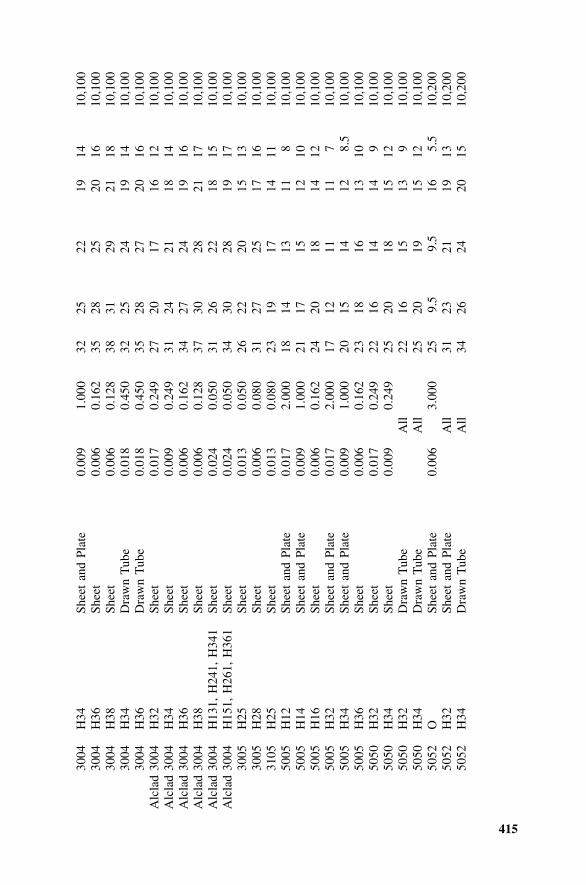
415
3004
H34
Shee
tan
dPl
ate
0.00
91.
000
3225
2219
1410
,100
3004
H36
Shee
t0.
006
0.16
235
2825
2016
10,1
0030
04H
38Sh
eet
0.00
60.
128
3831
2921
1810
,100
3004
H34
Dra
wn
Tub
e0.
018
0.45
032
2524
1914
10,1
0030
04H
36D
raw
nT
ube
0.01
80.
450
3528
2720
1610
,100
Alc
lad
3004
H32
Shee
t0.
017
0.24
927
2017
1612
10,1
00A
lcla
d30
04H
34Sh
eet
0.00
90.
249
3124
2118
1410
,100
Alc
lad
3004
H36
Shee
t0.
006
0.16
234
2724
1916
10,1
00A
lcla
d30
04H
38Sh
eet
0.00
60.
128
3730
2821
1710
,100
Alc
lad
3004
H13
1,H
241,
H34
1Sh
eet
0.02
40.
050
3126
2218
1510
,100
Alc
lad
3004
H15
1,H
261,
H36
1Sh
eet
0.02
40.
050
3430
2819
1710
,100
3005
H25
Shee
t0.
013
0.05
026
2220
1513
10,1
0030
05H
28Sh
eet
0.00
60.
080
3127
2517
1610
,100
3105
H25
Shee
t0.
013
0.08
023
1917
1411
10,1
0050
05H
12Sh
eet
and
Plat
e0.
017
2.00
018
1413
118
10,1
0050
05H
14Sh
eet
and
Plat
e0.
009
1.00
021
1715
1210
10,1
0050
05H
16Sh
eet
0.00
60.
162
2420
1814
1210
,100
5005
H32
Shee
tan
dPl
ate
0.01
72.
000
1712
1111
710
,100
5005
H34
Shee
tan
dPl
ate
0.00
91.
000
2015
1412
8.5
10,1
0050
05H
36Sh
eet
0.00
60.
162
2318
1613
1010
,100
5050
H32
Shee
t0.
017
0.24
922
1614
149
10,1
0050
50H
34Sh
eet
0.00
90.
249
2520
1815
1210
,100
5050
H32
Dra
wn
Tub
eA
ll22
1615
139
10,1
0050
50H
34D
raw
nT
ube
All
2520
1915
1210
,100
5052
OSh
eet
and
Plat
e0.
006
3.00
025
9.5
9.5
165.
510
,200
5052
H32
Shee
tan
dPl
ate
All
3123
2119
1310
,200
5052
H34
Dra
wn
Tub
eA
ll34
2624
2015
10,2
00
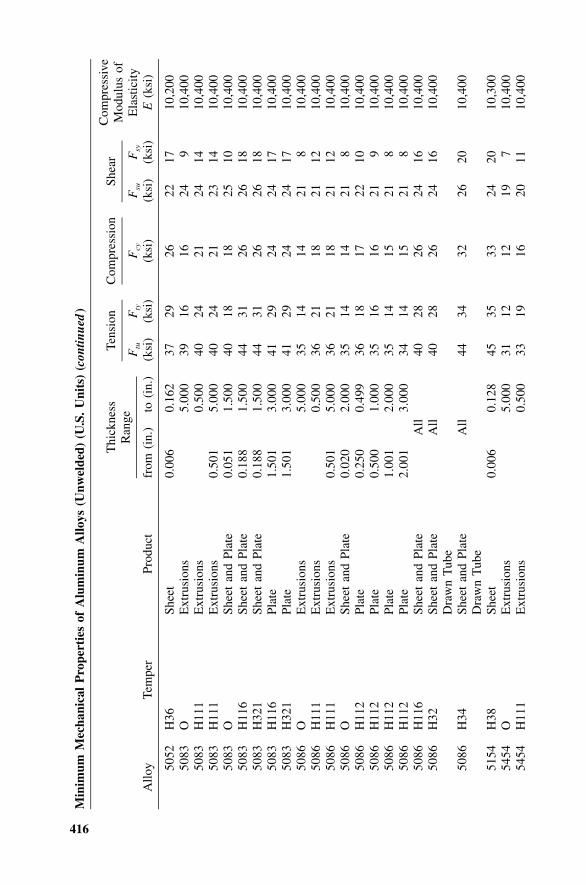
416
Min
imum
Mec
hani
cal
Pro
pert
ies
ofA
lum
inum
Allo
ys(U
nwel
ded)
(U.S
.U
nits
)(c
ontin
ued
)
Allo
yTe
mpe
rPr
oduc
t
Thi
ckne
ssR
ange
from
(in.
)to
(in.
)
Tens
ion
Ftu
(ksi
)F
ty
(ksi
)
Com
pres
sion
Fcy
(ksi
)
Shea
r
Fsu
(ksi
)F
sy
(ksi
)
Com
pres
sive
Mod
ulus
ofE
last
icity
E(k
si)
5052
H36
Shee
t0.
006
0.16
237
2926
2217
10,2
0050
83O
Ext
rusi
ons
5.00
039
1616
249
10,4
0050
83H
111
Ext
rusi
ons
0.50
040
2421
2414
10,4
0050
83H
111
Ext
rusi
ons
0.50
15.
000
4024
2123
1410
,400
5083
OSh
eet
and
Plat
e0.
051
1.50
040
1818
2510
10,4
0050
83H
116
Shee
tan
dPl
ate
0.18
81.
500
4431
2626
1810
,400
5083
H32
1Sh
eet
and
Plat
e0.
188
1.50
044
3126
2618
10,4
0050
83H
116
Plat
e1.
501
3.00
041
2924
2417
10,4
0050
83H
321
Plat
e1.
501
3.00
041
2924
2417
10,4
0050
86O
Ext
rusi
ons
5.00
035
1414
218
10,4
0050
86H
111
Ext
rusi
ons
0.50
036
2118
2112
10,4
0050
86H
111
Ext
rusi
ons
0.50
15.
000
3621
1821
1210
,400
5086
OSh
eet
and
Plat
e0.
020
2.00
035
1414
218
10,4
0050
86H
112
Plat
e0.
250
0.49
936
1817
2210
10,4
0050
86H
112
Plat
e0.
500
1.00
035
1616
219
10,4
0050
86H
112
Plat
e1.
001
2.00
035
1415
218
10,4
0050
86H
112
Plat
e2.
001
3.00
034
1415
218
10,4
0050
86H
116
Shee
tan
dPl
ate
All
4028
2624
1610
,400
5086
H32
Shee
tan
dPl
ate
Dra
wn
Tub
eA
ll40
2826
2416
10,4
00
5086
H34
Shee
tan
dPl
ate
Dra
wn
Tub
eA
ll44
3432
2620
10,4
00
5154
H38
Shee
t0.
006
0.12
845
3533
2420
10,3
0054
54O
Ext
rusi
ons
5.00
031
1212
197
10,4
0054
54H
111
Ext
rusi
ons
0.50
033
1916
2011
10,4
00
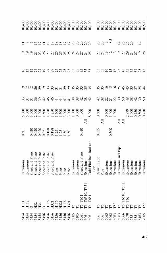
417
5454
H11
1E
xtru
sion
s0.
501
5.00
033
1916
1911
10,4
0054
54H
112
Ext
rusi
ons
5.00
031
1213
197
10,4
0054
54O
Shee
tan
dPl
ate
0.02
03.
000
3112
1219
710
,400
5454
H32
Shee
tan
dPl
ate
0.02
02.
000
3626
2421
1510
,400
5454
H34
Shee
tan
dPl
ate
0.02
01.
000
3929
2723
1710
,400
5456
OSh
eet
and
Plat
e0.
051
1.50
042
1919
2611
10,4
0054
56H
116
Shee
tan
dPl
ate
0.18
81.
250
4633
2727
1910
,400
5456
H32
1Sh
eet
and
Plat
e0.
188
1.25
046
3327
2719
10,4
0054
56H
116
Plat
e1.
251
1.50
044
3125
2518
10,4
0054
56H
321
Plat
e1.
251
1.50
044
3125
2518
10,4
0054
56H
116
Plat
e1.
501
3.00
041
2925
2517
10,4
0054
56H
321
Plat
e1.
501
3.00
041
2925
2517
10,4
0060
05T
5E
xtru
sion
s1.
000
3835
3524
2010
,100
6105
T5
Ext
rusi
ons
0.50
038
3535
2420
10,1
0060
61T
6,T
651
Shee
tan
dPl
ate
0.01
04.
000
4235
3527
2010
,100
6061
T6,
T65
10,
T65
11E
xtru
sion
sA
ll38
3535
2420
10,1
0060
61T
6,T
651
Col
d-Fi
nish
edR
odan
dB
ar8.
000
4235
3525
2010
,100
6061
T6
Dra
wn
Tub
e0.
025
0.50
042
3535
2720
10,1
0060
61T
6Pi
peA
ll38
3535
2420
10,1
0060
63T
5E
xtru
sion
s0.
500
2216
1613
910
,100
6063
T5
Ext
rusi
ons
0.50
01.
000
2115
1512
8.5
10,1
0060
63T
52E
xtru
sion
s1.
000
2216
1613
10,1
0060
63T
6E
xtru
sion
san
dPi
peA
ll30
2525
1914
10,1
0060
66T
6,T
6510
,T
6511
Ext
rusi
ons
All
5045
4527
2610
,100
6070
T6,
T62
Ext
rusi
ons
2.99
948
4545
2926
10,1
0063
51T
5E
xtru
sion
s1.
000
3835
3524
2010
,100
6351
T6
Ext
rusi
ons
0.75
042
3737
2710
,100
6463
T6
Ext
rusi
ons
0.50
030
2525
1914
10,1
0070
05T
53E
xtru
sion
s0.
750
5044
4328
10,5
00
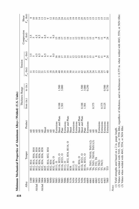
418
Min
imum
Mec
hani
cal
Pro
pert
ies
ofA
lum
inum
Allo
ys(W
elde
d)(U
.S.
Uni
ts)
Allo
yTe
mpe
rPr
oduc
t
Thi
ckne
ssR
ange
from
(in.
)to
(in.
)
Tens
ion
Ftu
(ksi
)F
ty(k
si)
Com
pres
sion
Fcy
(ksi
)Sh
ear
Fsu
(ksi
)
1100
H12
,H
14A
ll11
3.5
3.5
830
03H
12,
H14
,H
16,
H18
All
145
510
Alc
lad
3003
H12
,H
14,
H16
,H
18A
ll13
4.5
4.5
1030
04H
32,
H34
,H
36,
H38
All
228.
58.
514
Alc
lad
3004
H32
,H
34,
H36
,H
38A
ll21
88
1330
05H
25Sh
eet
176.
56.
512
5005
H12
,H
14,
H32
,H
34A
ll15
55
950
50H
32,
H34
All
186
612
5052
H32
,H
34,
OA
ll25
9.5
9.5
1650
83H
111,
OE
xtru
sion
s39
1615
2350
83H
116,
H32
1,O
Shee
tan
dPl
ate
0.18
81.
500
4018
1824
5083
H11
6,H
321,
OPl
ate
1.50
13.
000
3917
1724
5086
H11
1,O
Ext
rusi
ons
3514
1321
5086
H11
2,H
32,
H34
,H
116,
OSh
eet
and
Plat
e35
1414
2151
54H
38Sh
eet
3011
1119
5454
H11
1,O
Ext
rusi
ons
3112
1119
5454
H11
2E
xtru
sion
s31
1212
1954
54H
32,
H34
,O
Shee
tan
dPl
ate
3112
1219
5456
H11
6,H
321,
OSh
eet
and
Plat
e0.
188
1.50
042
1918
2554
56H
116,
H32
1,O
Plat
e1.
501
3.00
041
1817
2560
05T
5E
xtru
sion
s0.
250
2413
1315
6061
T6,
T65
1,T
6510
,T
6511
(2)
All
2415
1515
6061
T6,
T65
1,T
6510
,T
6511
(3)
All
0.37
524
1111
1560
63T
5,T
52,
T6
All
178
811
6351
T5,
T6(
2)E
xtru
sion
s24
1515
1563
51T
5,T
6(3)
Ext
rusi
ons
0.37
524
1111
1564
63T
6E
xtru
sion
s0.
125
0.50
017
88
1170
05T
53E
xtru
sion
s0.
750
4024
2422
Not
es (1)
Yie
ldst
reng
ths
ared
base
don
a2
in.
gaug
ele
ngth
.(2
)V
alue
sw
hen
wel
ded
with
5183
,53
56,
or55
56fil
ler,
rega
rdle
ssof
thic
knes
s,an
dto
thic
knes
ses
�0.
375
in.
whe
nw
elde
dw
ith40
43,
5554
,or
5654
fille
r.(3
)V
alue
sw
hen
wel
ded
with
4043
,55
54,
or56
54fil
ler.
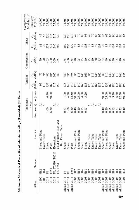
419
Min
imum
Mec
hani
cal
Pro
pert
ies
ofA
lum
inum
Allo
ys(U
nwel
ded)
(SI
Uni
ts)
Allo
yTe
mpe
rPr
oduc
t
Thi
ckne
ssR
ange
from
(mm
)to
(mm
)
Tens
ion
Ftu
(MPa
)F
ty
(MPa
)
Com
pres
sion
Fcy
(MPa
)
Shea
r
Fsu
(MPa
)F
sy
(MPa
)
Com
pres
sive
Mod
ulus
ofE
last
icity
E(M
Pa)
1100
H12
Shee
tan
dPl
ate
All
9575
7062
4569
,600
1100
H14
Dra
wn
Tub
eA
ll11
095
9070
5569
,600
2014
T6
Shee
t1.
006.
3045
540
040
527
523
075
,200
2014
T65
1Pl
ate
6.30
50.0
046
040
540
027
523
575
,200
2014
T6,
T65
10,
T65
11E
xtru
sion
sA
ll41
536
536
024
021
575
,200
2014
T6,
T65
1C
old-
Fini
shed
Rod
and
Bar
,D
raw
nT
ube
All
450
380
365
260
220
75,2
00
Alc
lad
2014
T6
Shee
t0.
631.
0043
538
038
526
022
074
,500
Alc
lad
2014
T6
Shee
t1.
006.
3044
039
540
027
023
074
,500
Alc
lad
2014
T65
1Pl
ate
6.30
12.5
044
039
538
527
023
074
,500
3003
H12
Shee
tan
dPl
ate
0.40
50.0
012
085
7075
4869
,600
3003
H14
Shee
tan
dPl
ate
0.20
25.0
014
011
595
8570
69,6
0030
03H
16Sh
eet
0.15
4.00
165
145
125
9585
69,6
0030
03H
18Sh
eet
0.15
3.20
185
165
140
105
9569
,600
3003
H12
Dra
wn
Tub
eA
ll12
085
7575
4869
,600
3003
H14
Dra
wn
Tub
eA
ll14
011
511
085
7069
,600
3003
H16
Dra
wn
Tub
eA
ll16
514
513
095
8569
,600
3003
H18
Dra
wn
Tub
eA
ll18
516
514
510
595
69,6
00A
lcla
d30
03H
12Sh
eet
and
Plat
e0.
4050
.00
115
8062
7045
69,6
00A
lcla
d30
03H
14Sh
eet
and
Plat
e0.
2025
.00
135
110
9085
6269
,600
Alc
lad
3003
H16
Shee
t0.
154.
0016
014
011
595
8569
,600
Alc
lad
3003
H18
Shee
t0.
153.
2018
016
013
010
590
69,6
00A
lcla
d30
03H
14D
raw
nT
ube
0.63
6.30
135
110
105
8562
69,6
00A
lcla
d30
03H
18D
raw
nT
ube
0.25
12.5
018
016
014
010
590
69,6
0030
04H
32Sh
eet
and
Plat
e0.
4050
.00
190
145
125
115
8569
,600
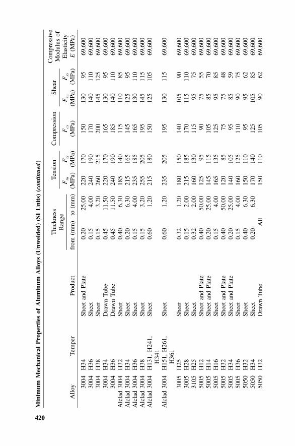
420
Min
imum
Mec
hani
cal
Pro
pert
ies
ofA
lum
inum
Allo
ys(U
nwel
ded)
(SI
Uni
ts)
(con
tinue
d)
Allo
yTe
mpe
rPr
oduc
t
Thi
ckne
ssR
ange
from
(mm
)to
(mm
)
Tens
ion
Ftu
(MPa
)F
ty
(MPa
)
Com
pres
sion
Fcy
(MPa
)
Shea
r
Fsu
(MPa
)F
sy
(MPa
)
Com
pres
sive
Mod
ulus
ofE
last
icity
E(M
Pa)
3004
H34
Shee
tan
dPl
ate
0.20
25.0
022
017
015
013
095
69,6
0030
04H
36Sh
eet
0.15
4.00
240
190
170
140
110
69,6
0030
04H
38Sh
eet
0.15
3.20
260
215
200
145
125
69,6
0030
04H
34D
raw
nT
ube
0.45
11.5
022
017
016
513
095
69,6
0030
04H
36D
raw
nT
ube
0.45
11.5
024
019
018
514
011
069
,600
Alc
lad
3004
H32
Shee
t0.
406.
3018
514
011
511
085
69,6
00A
lcla
d30
04H
34Sh
eet
0.20
6.30
215
165
145
125
9569
,600
Alc
lad
3004
H36
Shee
t0.
154.
0023
518
516
513
011
069
,600
Alc
lad
3004
H38
Shee
t0.
153.
2025
520
519
514
511
569
,600
Alc
lad
3004
H13
1,H
241,
H34
1Sh
eet
0.60
1.20
215
180
150
125
105
69,6
00
Alc
lad
3004
H15
1,H
261,
H36
1Sh
eet
0.60
1.20
235
205
195
130
115
69,6
00
3005
H25
Shee
t0.
321.
2018
015
014
010
590
69,6
0030
05H
28Sh
eet
0.15
2.00
215
185
170
115
110
69,6
0031
05H
25Sh
eet
0.32
2.00
160
130
115
9575
69,6
0050
05H
12Sh
eet
and
Plat
e0.
4050
.00
125
9590
7555
69,6
0050
05H
14Sh
eet
and
Plat
e0.
2025
.00
145
115
105
8570
69,6
0050
05H
16Sh
eet
0.15
4.00
165
135
125
9585
69,6
0050
05H
32Sh
eet
and
Plat
e0.
4050
.00
120
8575
7548
69,6
0050
05H
34Sh
eet
and
Plat
e0.
2025
.00
140
105
9585
5969
,600
5005
H36
Shee
t0.
154.
0016
012
511
090
7569
,600
5050
H32
Shee
t0.
406.
3015
011
095
9562
69,6
0050
50H
34Sh
eet
0.20
6.30
170
140
125
105
8569
,600
5050
H32
Dra
wn
Tub
eA
ll15
011
010
590
6269
,600
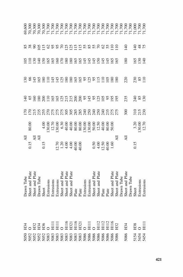
421
5050
H34
Dra
wn
Tub
eA
ll17
014
013
010
585
69,6
0050
52O
Shee
tan
dPl
ate
0.15
80.0
017
065
6611
038
70,3
0050
52H
32Sh
eet
and
Plat
eA
ll21
516
014
513
090
70,3
0050
52H
34D
raw
nT
ube
All
235
180
165
140
105
70,3
0050
52H
36Sh
eet
0.15
4.00
255
200
180
150
115
70,3
0050
83O
Ext
rusi
ons
130.
0027
011
011
016
562
71,7
0050
83H
111
Ext
rusi
ons
12.7
027
516
514
516
595
71,7
0050
83H
111
Ext
rusi
ons
12.7
013
0.00
275
165
145
160
9571
,700
5083
OSh
eet
and
Plat
e1.
206.
3027
512
512
517
070
71,7
0050
83H
116
Shee
tan
dPl
ate
4.00
40.0
030
521
518
018
012
571
,700
5083
H32
1Sh
eet
and
Plat
e4.
0040
.00
305
215
180
180
125
71,7
0050
83H
116
Plat
e40
.00
80.0
028
520
016
516
511
571
,700
5083
H32
1Pl
ate
40.0
080
.00
285
200
165
165
115
71,7
0050
86O
Ext
rusi
ons
130.
0024
095
9514
555
71,7
0050
86H
111
Ext
rusi
ons
130.
0025
014
512
514
585
71,7
0050
86O
Shee
tan
dPl
ate
0.50
50.0
024
095
9514
555
71,7
0050
86H
112
Shee
tan
dPl
ate
4.00
12.5
025
012
511
515
070
71,7
0050
86H
112
Plat
e12
.50
40.0
024
010
511
014
562
71,7
0050
86H
112
Plat
e40
.00
80.0
023
595
105
145
5571
,700
5086
H11
6Sh
eet
and
Plat
e1.
6050
.00
275
195
180
165
110
71,7
0050
86H
32Sh
eet
and
Plat
eA
ll27
519
518
016
511
071
,700
Dra
wn
Tub
e71
,700
5086
H34
Shee
tan
dPl
ate
All
300
235
220
180
140
71,7
00D
raw
nT
ube
71,7
0051
54H
38Sh
eet
0.15
3.20
310
240
230
165
140
71,0
0054
54O
Ext
rusi
ons
130.
0021
585
8513
048
71,7
0054
54H
111
Ext
rusi
ons
12.7
023
013
011
014
075
71,7
00
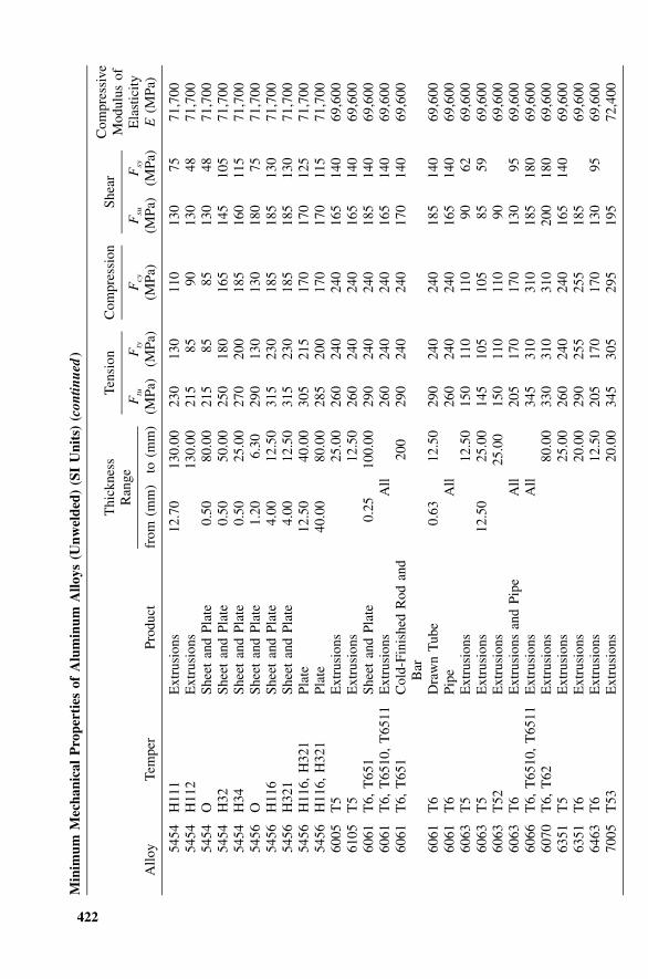
422
Min
imum
Mec
hani
cal
Pro
pert
ies
ofA
lum
inum
Allo
ys(U
nwel
ded)
(SI
Uni
ts)
(con
tinue
d)
Allo
yTe
mpe
rPr
oduc
t
Thi
ckne
ssR
ange
from
(mm
)to
(mm
)
Tens
ion
Ftu
(MPa
)F
ty
(MPa
)
Com
pres
sion
Fcy
(MPa
)
Shea
r
Fsu
(MPa
)F
sy
(MPa
)
Com
pres
sive
Mod
ulus
ofE
last
icity
E(M
Pa)
5454
H11
1E
xtru
sion
s12
.70
130.
0023
013
011
013
075
71,7
0054
54H
112
Ext
rusi
ons
130.
0021
585
9013
048
71,7
0054
54O
Shee
tan
dPl
ate
0.50
80.0
021
585
8513
048
71,7
0054
54H
32Sh
eet
and
Plat
e0.
5050
.00
250
180
165
145
105
71,7
0054
54H
34Sh
eet
and
Plat
e0.
5025
.00
270
200
185
160
115
71,7
0054
56O
Shee
tan
dPl
ate
1.20
6.30
290
130
130
180
7571
,700
5456
H11
6Sh
eet
and
Plat
e4.
0012
.50
315
230
185
185
130
71,7
0054
56H
321
Shee
tan
dPl
ate
4.00
12.5
031
523
018
518
513
071
,700
5456
H11
6,H
321
Plat
e12
.50
40.0
030
521
517
017
012
571
,700
5456
H11
6,H
321
Plat
e40
.00
80.0
028
520
017
017
011
571
,700
6005
T5
Ext
rusi
ons
25.0
026
024
024
016
514
069
,600
6105
T5
Ext
rusi
ons
12.5
026
024
024
016
514
069
,600
6061
T6,
T65
1Sh
eet
and
Plat
e0.
2510
0.00
290
240
240
185
140
69,6
0060
61T
6,T
6510
,T
6511
Ext
rusi
ons
All
260
240
240
165
140
69,6
0060
61T
6,T
651
Col
d-Fi
nish
edR
odan
dB
ar20
029
024
024
017
014
069
,600
6061
T6
Dra
wn
Tub
e0.
6312
.50
290
240
240
185
140
69,6
0060
61T
6Pi
peA
ll26
024
024
016
514
069
,600
6063
T5
Ext
rusi
ons
12.5
015
011
011
090
6269
,600
6063
T5
Ext
rusi
ons
12.5
025
.00
145
105
105
8559
69,6
0060
63T
52E
xtru
sion
s25
.00
150
110
110
9069
,600
6063
T6
Ext
rusi
ons
and
Pipe
All
205
170
170
130
9569
,600
6066
T6,
T65
10,
T65
11E
xtru
sion
sA
ll34
531
031
018
518
069
,600
6070
T6,
T62
Ext
rusi
ons
80.0
033
031
031
020
018
069
,600
6351
T5
Ext
rusi
ons
25.0
026
024
024
016
514
069
,600
6351
T6
Ext
rusi
ons
20.0
029
025
525
518
569
,600
6463
T6
Ext
rusi
ons
12.5
020
517
017
013
095
69,6
0070
05T
53E
xtru
sion
s20
.00
345
305
295
195
72,4
00
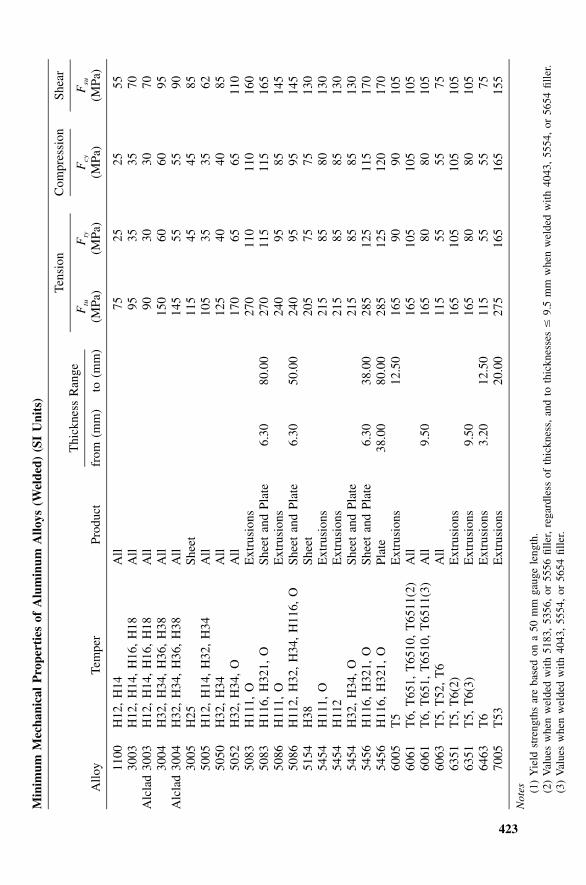
423
Min
imum
Mec
hani
cal
Pro
pert
ies
ofA
lum
inum
Allo
ys(W
elde
d)(S
IU
nits
)
Allo
yTe
mpe
rPr
oduc
t
Thi
ckne
ssR
ange
from
(mm
)to
(mm
)
Tens
ion
Ftu
(MPa
)F
ty
(MPa
)
Com
pres
sion
Fcy
(MPa
)
Shea
r
Fsu
(MPa
)
1100
H12
,H
14A
ll75
2525
5530
03H
12,
H14
,H
16,
H18
All
9535
3570
Alc
lad
3003
H12
,H
14,
H16
,H
18A
ll90
3030
7030
04H
32,
H34
,H
36,
H38
All
150
6060
95A
lcla
d30
04H
32,
H34
,H
36,
H38
All
145
5555
9030
05H
25Sh
eet
115
4545
8550
05H
12,
H14
,H
32,
H34
All
105
3535
6250
50H
32,
H34
All
125
4040
8550
52H
32,
H34
,O
All
170
6565
110
5083
H11
1,O
Ext
rusi
ons
270
110
110
160
5083
H11
6,H
321,
OSh
eet
and
Plat
e6.
3080
.00
270
115
115
165
5086
H11
1,O
Ext
rusi
ons
240
9585
145
5086
H11
2,H
32,
H34
,H
116,
OSh
eet
and
Plat
e6.
3050
.00
240
9595
145
5154
H38
Shee
t20
575
7513
054
54H
111,
OE
xtru
sion
s21
585
8013
054
54H
112
Ext
rusi
ons
215
8585
130
5454
H32
,H
34,
OSh
eet
and
Plat
e21
585
8513
054
56H
116,
H32
1,O
Shee
tan
dPl
ate
6.30
38.0
028
512
511
517
054
56H
116,
H32
1,O
Plat
e38
.00
80.0
028
512
512
017
060
05T
5E
xtru
sion
s12
.50
165
9090
105
6061
T6,
T65
1,T
6510
,T
6511
(2)
All
165
105
105
105
6061
T6,
T65
1,T
6510
,T
6511
(3)
All
9.50
165
8080
105
6063
T5,
T52
,T
6A
ll11
555
5575
6351
T5,
T6(
2)E
xtru
sion
s16
510
510
510
563
51T
5,T
6(3)
Ext
rusi
ons
9.50
165
8080
105
6463
T6
Ext
rusi
ons
3.20
12.5
011
555
5575
7005
T53
Ext
rusi
ons
20.0
027
516
516
515
5
Not
es (1)
Yie
ldst
reng
ths
are
base
don
a50
mm
gaug
ele
ngth
.(2
)V
alue
sw
hen
wel
ded
with
5183
,53
56,
or55
56fil
ler,
rega
rdle
ssof
thic
knes
s,an
dto
thic
knes
ses
�9.
5m
mw
hen
wel
ded
with
4043
,55
54,
or56
54fil
ler.
(3)
Val
ues
whe
nw
elde
dw
ith40
43,
5554
,or
5654
fille
r.

425
APPENDIX DAllowable Stresses for Elements ofCommon Aluminum Shapes
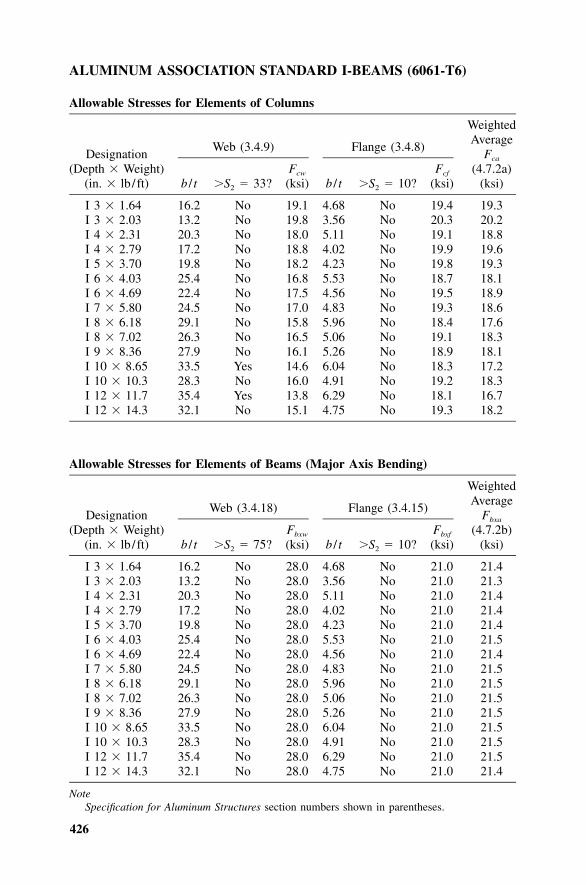
426
ALUMINUM ASSOCIATION STANDARD I-BEAMS (6061-T6)
Allowable Stresses for Elements of Columns
Designation(Depth � Weight)
(in. � lb / ft)
Web (3.4.9)
b / t �S2 � 33?Fcw
(ksi)
Flange (3.4.8)
b / t �S2 � 10?Fcf
(ksi)
WeightedAverage
Fca
(4.7.2a)(ksi)
I 3 � 1.64 16.2 No 19.1 4.68 No 19.4 19.3I 3 � 2.03 13.2 No 19.8 3.56 No 20.3 20.2I 4 � 2.31 20.3 No 18.0 5.11 No 19.1 18.8I 4 � 2.79 17.2 No 18.8 4.02 No 19.9 19.6I 5 � 3.70 19.8 No 18.2 4.23 No 19.8 19.3I 6 � 4.03 25.4 No 16.8 5.53 No 18.7 18.1I 6 � 4.69 22.4 No 17.5 4.56 No 19.5 18.9I 7 � 5.80 24.5 No 17.0 4.83 No 19.3 18.6I 8 � 6.18 29.1 No 15.8 5.96 No 18.4 17.6I 8 � 7.02 26.3 No 16.5 5.06 No 19.1 18.3I 9 � 8.36 27.9 No 16.1 5.26 No 18.9 18.1I 10 � 8.65 33.5 Yes 14.6 6.04 No 18.3 17.2I 10 � 10.3 28.3 No 16.0 4.91 No 19.2 18.3I 12 � 11.7 35.4 Yes 13.8 6.29 No 18.1 16.7I 12 � 14.3 32.1 No 15.1 4.75 No 19.3 18.2
Allowable Stresses for Elements of Beams (Major Axis Bending)
Designation(Depth � Weight)
(in. � lb / ft)
Web (3.4.18)
b / t �S2 � 75?Fbxw
(ksi)
Flange (3.4.15)
b / t �S2 � 10?Fbxf
(ksi)
WeightedAverage
Fbxa
(4.7.2b)(ksi)
I 3 � 1.64 16.2 No 28.0 4.68 No 21.0 21.4I 3 � 2.03 13.2 No 28.0 3.56 No 21.0 21.3I 4 � 2.31 20.3 No 28.0 5.11 No 21.0 21.4I 4 � 2.79 17.2 No 28.0 4.02 No 21.0 21.4I 5 � 3.70 19.8 No 28.0 4.23 No 21.0 21.4I 6 � 4.03 25.4 No 28.0 5.53 No 21.0 21.5I 6 � 4.69 22.4 No 28.0 4.56 No 21.0 21.4I 7 � 5.80 24.5 No 28.0 4.83 No 21.0 21.5I 8 � 6.18 29.1 No 28.0 5.96 No 21.0 21.5I 8 � 7.02 26.3 No 28.0 5.06 No 21.0 21.5I 9 � 8.36 27.9 No 28.0 5.26 No 21.0 21.5I 10 � 8.65 33.5 No 28.0 6.04 No 21.0 21.5I 10 � 10.3 28.3 No 28.0 4.91 No 21.0 21.5I 12 � 11.7 35.4 No 28.0 6.29 No 21.0 21.5I 12 � 14.3 32.1 No 28.0 4.75 No 21.0 21.4
NoteSpecification for Aluminum Structures section numbers shown in parentheses.
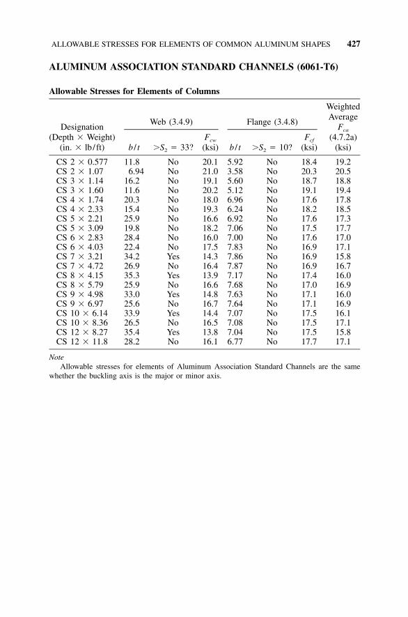
ALLOWABLE STRESSES FOR ELEMENTS OF COMMON ALUMINUM SHAPES 427
ALUMINUM ASSOCIATION STANDARD CHANNELS (6061-T6)
Allowable Stresses for Elements of Columns
Designation(Depth � Weight)
(in. � lb / ft)
Web (3.4.9)
b / t �S2 � 33?Fcw
(ksi)
Flange (3.4.8)
b / t �S2 � 10?Fcf
(ksi)
WeightedAverage
Fca
(4.7.2a)(ksi)
CS 2 � 0.577 11.8 No 20.1 5.92 No 18.4 19.2CS 2 � 1.07 6.94 No 21.0 3.58 No 20.3 20.5CS 3 � 1.14 16.2 No 19.1 5.60 No 18.7 18.8CS 3 � 1.60 11.6 No 20.2 5.12 No 19.1 19.4CS 4 � 1.74 20.3 No 18.0 6.96 No 17.6 17.8CS 4 � 2.33 15.4 No 19.3 6.24 No 18.2 18.5CS 5 � 2.21 25.9 No 16.6 6.92 No 17.6 17.3CS 5 � 3.09 19.8 No 18.2 7.06 No 17.5 17.7CS 6 � 2.83 28.4 No 16.0 7.00 No 17.6 17.0CS 6 � 4.03 22.4 No 17.5 7.83 No 16.9 17.1CS 7 � 3.21 34.2 Yes 14.3 7.86 No 16.9 15.8CS 7 � 4.72 26.9 No 16.4 7.87 No 16.9 16.7CS 8 � 4.15 35.3 Yes 13.9 7.17 No 17.4 16.0CS 8 � 5.79 25.9 No 16.6 7.68 No 17.0 16.9CS 9 � 4.98 33.0 Yes 14.8 7.63 No 17.1 16.0CS 9 � 6.97 25.6 No 16.7 7.64 No 17.1 16.9CS 10 � 6.14 33.9 Yes 14.4 7.07 No 17.5 16.1CS 10 � 8.36 26.5 No 16.5 7.08 No 17.5 17.1CS 12 � 8.27 35.4 Yes 13.8 7.04 No 17.5 15.8CS 12 � 11.8 28.2 No 16.1 6.77 No 17.7 17.1
NoteAllowable stresses for elements of Aluminum Association Standard Channels are the same
whether the buckling axis is the major or minor axis.
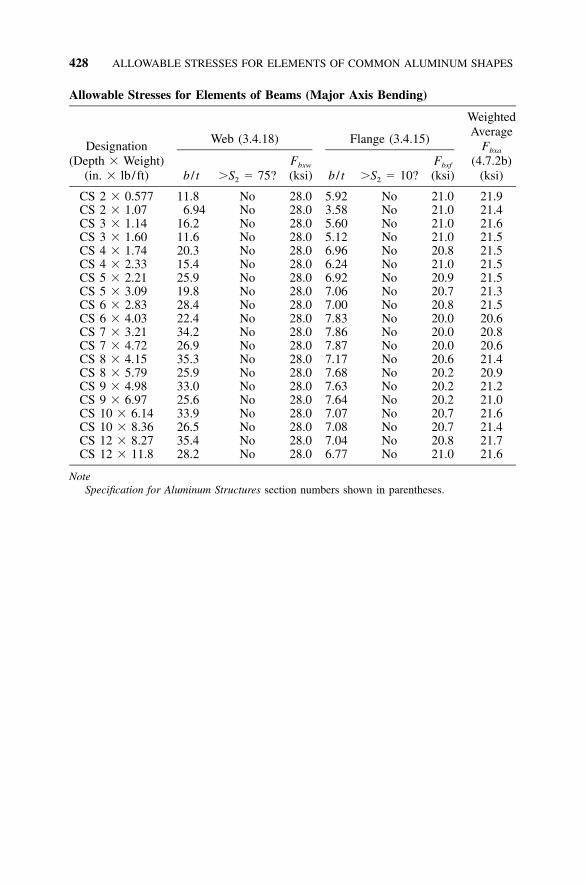
428 ALLOWABLE STRESSES FOR ELEMENTS OF COMMON ALUMINUM SHAPES
Allowable Stresses for Elements of Beams (Major Axis Bending)
Designation(Depth � Weight)
(in. � lb / ft)
Web (3.4.18)
b / t �S2 � 75?Fbxw
(ksi)
Flange (3.4.15)
b / t �S2 � 10?Fbxf
(ksi)
WeightedAverage
Fbxa
(4.7.2b)(ksi)
CS 2 � 0.577 11.8 No 28.0 5.92 No 21.0 21.9CS 2 � 1.07 6.94 No 28.0 3.58 No 21.0 21.4CS 3 � 1.14 16.2 No 28.0 5.60 No 21.0 21.6CS 3 � 1.60 11.6 No 28.0 5.12 No 21.0 21.5CS 4 � 1.74 20.3 No 28.0 6.96 No 20.8 21.5CS 4 � 2.33 15.4 No 28.0 6.24 No 21.0 21.5CS 5 � 2.21 25.9 No 28.0 6.92 No 20.9 21.5CS 5 � 3.09 19.8 No 28.0 7.06 No 20.7 21.3CS 6 � 2.83 28.4 No 28.0 7.00 No 20.8 21.5CS 6 � 4.03 22.4 No 28.0 7.83 No 20.0 20.6CS 7 � 3.21 34.2 No 28.0 7.86 No 20.0 20.8CS 7 � 4.72 26.9 No 28.0 7.87 No 20.0 20.6CS 8 � 4.15 35.3 No 28.0 7.17 No 20.6 21.4CS 8 � 5.79 25.9 No 28.0 7.68 No 20.2 20.9CS 9 � 4.98 33.0 No 28.0 7.63 No 20.2 21.2CS 9 � 6.97 25.6 No 28.0 7.64 No 20.2 21.0CS 10 � 6.14 33.9 No 28.0 7.07 No 20.7 21.6CS 10 � 8.36 26.5 No 28.0 7.08 No 20.7 21.4CS 12 � 8.27 35.4 No 28.0 7.04 No 20.8 21.7CS 12 � 11.8 28.2 No 28.0 6.77 No 21.0 21.6
NoteSpecification for Aluminum Structures section numbers shown in parentheses.
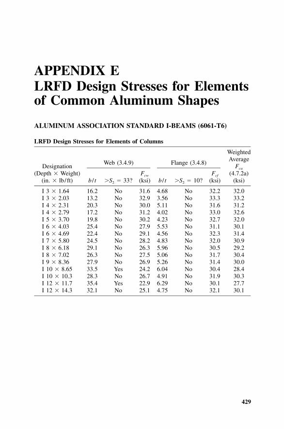
429
APPENDIX ELRFD Design Stresses for Elementsof Common Aluminum Shapes
ALUMINUM ASSOCIATION STANDARD I-BEAMS (6061-T6)
LRFD Design Stresses for Elements of Columns
Designation(Depth � Weight)
(in. � lb / ft)
Web (3.4.9)
b / t �S2 � 33?Fcw
(ksi)
Flange (3.4.8)
b / t �S2 � 10?Fcf
(ksi)
WeightedAverage
Fca
(4.7.2a)(ksi)
I 3 � 1.64 16.2 No 31.6 4.68 No 32.2 32.0I 3 � 2.03 13.2 No 32.9 3.56 No 33.3 33.2I 4 � 2.31 20.3 No 30.0 5.11 No 31.6 31.2I 4 � 2.79 17.2 No 31.2 4.02 No 33.0 32.6I 5 � 3.70 19.8 No 30.2 4.23 No 32.7 32.0I 6 � 4.03 25.4 No 27.9 5.53 No 31.1 30.1I 6 � 4.69 22.4 No 29.1 4.56 No 32.3 31.4I 7 � 5.80 24.5 No 28.2 4.83 No 32.0 30.9I 8 � 6.18 29.1 No 26.3 5.96 No 30.5 29.2I 8 � 7.02 26.3 No 27.5 5.06 No 31.7 30.4I 9 � 8.36 27.9 No 26.9 5.26 No 31.4 30.0I 10 � 8.65 33.5 Yes 24.2 6.04 No 30.4 28.4I 10 � 10.3 28.3 No 26.7 4.91 No 31.9 30.3I 12 � 11.7 35.4 Yes 22.9 6.29 No 30.1 27.7I 12 � 14.3 32.1 No 25.1 4.75 No 32.1 30.1
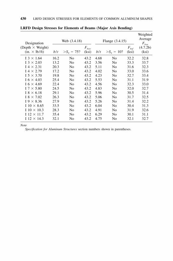
430 LRFD DESIGN STRESSES FOR ELEMENTS OF COMMON ALUMINUM SHAPES
LRFD Design Stresses for Elements of Beams (Major Axis Bending)
Designation(Depth � Weight)
(in. � lb / ft)
Web (3.4.18)
b / t �S2 � 75?Fbxw
(ksi)
Flange (3.4.15)
b / t �S2 � 10?Fbxf
(ksi)
WeightedAverage
Fbxa
(4.7.2b)(ksi)
I 3 � 1.64 16.2 No 43.2 4.68 No 32.2 32.8I 3 � 2.03 13.2 No 43.2 3.56 No 33.3 33.7I 4 � 2.31 20.3 No 43.2 5.11 No 31.6 32.3I 4 � 2.79 17.2 No 43.2 4.02 No 33.0 33.6I 5 � 3.70 19.8 No 43.2 4.23 No 32.7 33.4I 6 � 4.03 25.4 No 43.2 5.53 No 31.1 31.9I 6 � 4.69 22.4 No 43.2 4.56 No 32.3 33.0I 7 � 5.80 24.5 No 43.2 4.83 No 32.0 32.7I 8 � 6.18 29.1 No 43.2 5.96 No 30.5 31.4I 8 � 7.02 26.3 No 43.2 5.06 No 31.7 32.5I 9 � 8.36 27.9 No 43.2 5.26 No 31.4 32.2I 10 � 8.65 33.5 No 43.2 6.04 No 30.4 31.3I 10 � 10.3 28.3 No 43.2 4.91 No 31.9 32.6I 12 � 11.7 35.4 No 43.2 6.29 No 30.1 31.1I 12 � 14.3 32.1 No 43.2 4.75 No 32.1 32.7
NoteSpecification for Aluminum Structures section numbers shown in parentheses.
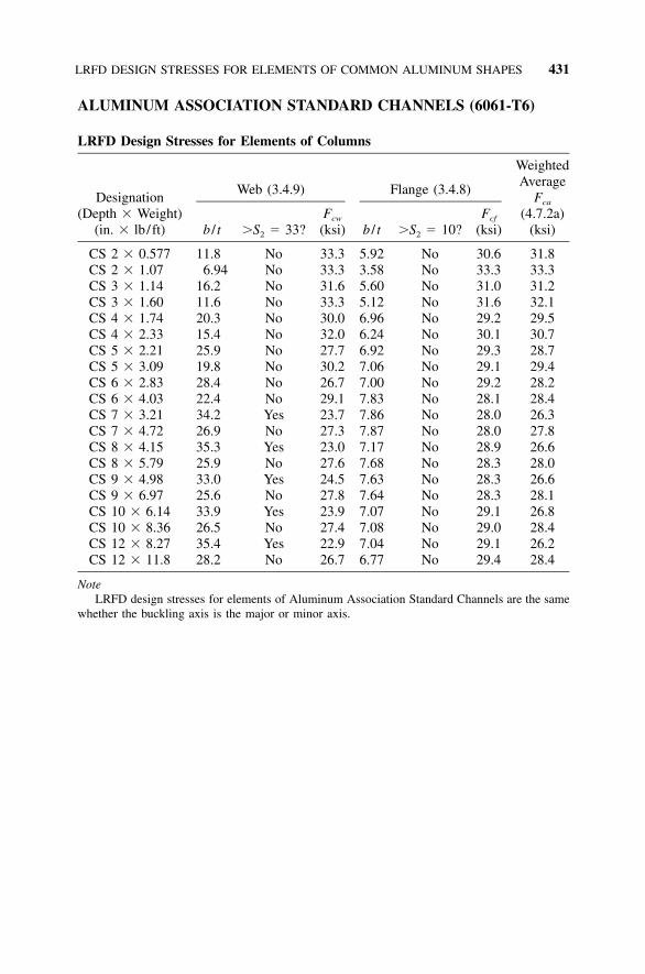
LRFD DESIGN STRESSES FOR ELEMENTS OF COMMON ALUMINUM SHAPES 431
ALUMINUM ASSOCIATION STANDARD CHANNELS (6061-T6)
LRFD Design Stresses for Elements of Columns
Designation(Depth � Weight)
(in. � lb / ft)
Web (3.4.9)
b / t �S2 � 33?Fcw
(ksi)
Flange (3.4.8)
b / t �S2 � 10?Fcf
(ksi)
WeightedAverage
Fca
(4.7.2a)(ksi)
CS 2 � 0.577 11.8 No 33.3 5.92 No 30.6 31.8CS 2 � 1.07 6.94 No 33.3 3.58 No 33.3 33.3CS 3 � 1.14 16.2 No 31.6 5.60 No 31.0 31.2CS 3 � 1.60 11.6 No 33.3 5.12 No 31.6 32.1CS 4 � 1.74 20.3 No 30.0 6.96 No 29.2 29.5CS 4 � 2.33 15.4 No 32.0 6.24 No 30.1 30.7CS 5 � 2.21 25.9 No 27.7 6.92 No 29.3 28.7CS 5 � 3.09 19.8 No 30.2 7.06 No 29.1 29.4CS 6 � 2.83 28.4 No 26.7 7.00 No 29.2 28.2CS 6 � 4.03 22.4 No 29.1 7.83 No 28.1 28.4CS 7 � 3.21 34.2 Yes 23.7 7.86 No 28.0 26.3CS 7 � 4.72 26.9 No 27.3 7.87 No 28.0 27.8CS 8 � 4.15 35.3 Yes 23.0 7.17 No 28.9 26.6CS 8 � 5.79 25.9 No 27.6 7.68 No 28.3 28.0CS 9 � 4.98 33.0 Yes 24.5 7.63 No 28.3 26.6CS 9 � 6.97 25.6 No 27.8 7.64 No 28.3 28.1CS 10 � 6.14 33.9 Yes 23.9 7.07 No 29.1 26.8CS 10 � 8.36 26.5 No 27.4 7.08 No 29.0 28.4CS 12 � 8.27 35.4 Yes 22.9 7.04 No 29.1 26.2CS 12 � 11.8 28.2 No 26.7 6.77 No 29.4 28.4
NoteLRFD design stresses for elements of Aluminum Association Standard Channels are the same
whether the buckling axis is the major or minor axis.
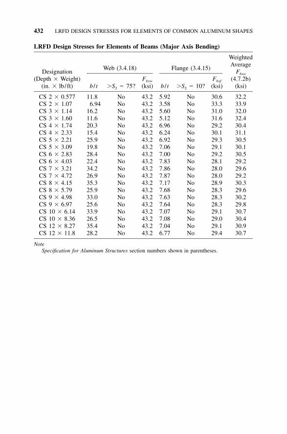
432 LRFD DESIGN STRESSES FOR ELEMENTS OF COMMON ALUMINUM SHAPES
LRFD Design Stresses for Elements of Beams (Major Axis Bending)
Designation(Depth � Weight)
(in. � lb / ft)
Web (3.4.18)
b / t �S2 � 75?Fbxw
(ksi)
Flange (3.4.15)
b / t �S2 � 10?Fbxf
(ksi)
WeightedAverage
Fbxa
(4.7.2b)(ksi)
CS 2 � 0.577 11.8 No 43.2 5.92 No 30.6 32.2CS 2 � 1.07 6.94 No 43.2 3.58 No 33.3 33.9CS 3 � 1.14 16.2 No 43.2 5.60 No 31.0 32.0CS 3 � 1.60 11.6 No 43.2 5.12 No 31.6 32.4CS 4 � 1.74 20.3 No 43.2 6.96 No 29.2 30.4CS 4 � 2.33 15.4 No 43.2 6.24 No 30.1 31.1CS 5 � 2.21 25.9 No 43.2 6.92 No 29.3 30.5CS 5 � 3.09 19.8 No 43.2 7.06 No 29.1 30.1CS 6 � 2.83 28.4 No 43.2 7.00 No 29.2 30.5CS 6 � 4.03 22.4 No 43.2 7.83 No 28.1 29.2CS 7 � 3.21 34.2 No 43.2 7.86 No 28.0 29.6CS 7 � 4.72 26.9 No 43.2 7.87 No 28.0 29.2CS 8 � 4.15 35.3 No 43.2 7.17 No 28.9 30.3CS 8 � 5.79 25.9 No 43.2 7.68 No 28.3 29.6CS 9 � 4.98 33.0 No 43.2 7.63 No 28.3 30.2CS 9 � 6.97 25.6 No 43.2 7.64 No 28.3 29.8CS 10 � 6.14 33.9 No 43.2 7.07 No 29.1 30.7CS 10 � 8.36 26.5 No 43.2 7.08 No 29.0 30.4CS 12 � 8.27 35.4 No 43.2 7.04 No 29.1 30.9CS 12 � 11.8 28.2 No 43.2 6.77 No 29.4 30.7
NoteSpecification for Aluminum Structures section numbers shown in parentheses.
433
APPENDIX FColumn Buckling Allowable Stress
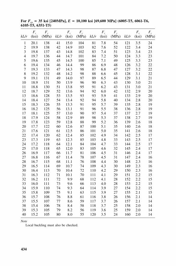
434
For Fcy � 35 ksi [240MPa], E � 10,100 ksi [69,600 MPa] (6005-T5, 6061-T6,6105-T5, 6351-T5)
kL/rFc
(ksi)Fc
(MPa) kL/rFc
(ksi)Fc
(MPa) kL/rFc
(ksi)Fc
(MPa) kL/rFc
(ksi)Fc
(MPa)
1 20.1 138 41 15.0 104 81 7.8 54 121 3.5 242 19.9 138 42 14.9 103 82 7.6 52 122 3.4 243 19.8 137 43 14.8 102 83 7.4 51 123 3.4 234 19.7 136 44 14.7 101 84 7.2 50 124 3.3 235 19.6 135 45 14.5 100 85 7.1 49 125 3.3 236 19.4 134 46 14.4 99 86 6.9 48 126 3.2 227 19.3 133 47 14.3 98 87 6.8 47 127 3.2 228 19.2 132 48 14.2 98 88 6.6 45 128 3.1 229 19.1 131 49 14.0 97 89 6.5 44 129 3.1 21
10 18.9 131 50 13.9 96 90 6.3 43 130 3.0 2111 18.8 130 51 13.8 95 91 6.2 43 131 3.0 2112 18.7 129 52 13.6 94 92 6.0 42 132 2.9 2013 18.6 128 53 13.5 93 93 5.9 41 133 2.9 2014 18.4 127 54 13.4 92 94 5.8 40 134 2.8 2015 18.3 126 55 13.3 91 95 5.7 39 135 2.8 1916 18.2 125 56 13.1 91 96 5.5 38 136 2.8 1917 18.1 125 57 13.0 90 97 5.4 37 137 2.7 1918 17.9 124 58 12.9 89 98 5.3 37 138 2.7 1919 17.8 123 59 12.8 88 99 5.2 36 139 2.6 1820 17.7 122 60 12.6 87 100 5.1 35 140 2.6 1821 17.6 121 61 12.5 86 101 5.0 35 141 2.6 1822 17.4 120 62 12.4 85 102 4.9 34 142 2.5 1723 17.3 119 63 12.3 85 103 4.8 33 143 2.5 1724 17.2 118 64 12.1 84 104 4.7 33 144 2.5 1725 17.0 118 65 12.0 83 105 4.6 32 145 2.4 1726 16.9 117 66 11.7 81 106 4.5 31 146 2.4 1727 16.8 116 67 11.4 78 107 4.5 31 147 2.4 1628 16.7 115 68 11.1 76 108 4.4 30 148 2.3 1629 16.5 114 69 10.7 74 109 4.3 30 149 2.3 1630 16.4 113 70 10.4 72 110 4.2 29 150 2.3 1631 16.3 112 71 10.1 70 111 4.1 29 151 2.2 1532 16.2 111 72 9.9 68 112 4.1 28 152 2.2 1533 16.0 111 73 9.6 66 113 4.0 28 153 2.2 1534 15.9 110 74 9.3 64 114 3.9 27 154 2.2 1535 15.8 109 75 9.1 63 115 3.9 27 155 2.1 1536 15.7 108 76 8.8 61 116 3.8 26 156 2.1 1437 15.5 107 77 8.6 59 117 3.7 26 157 2.1 1438 15.4 106 78 8.4 58 118 3.7 25 158 2.0 1439 15.3 105 79 8.2 56 119 3.6 25 159 2.0 1440 15.2 105 80 8.0 55 120 3.5 24 160 2.0 14
NoteLocal buckling must also be checked.
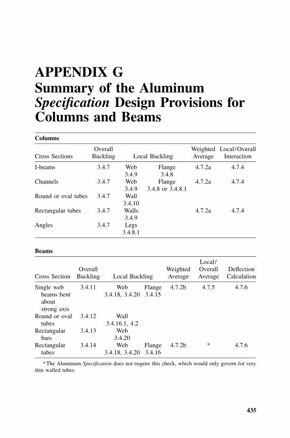
435
APPENDIX GSummary of the AluminumSpecification Design Provisions forColumns and BeamsColumns
Cross SectionsOverall
Buckling Local BucklingWeightedAverage
Local /OverallInteraction
I-beams 3.4.7 Web3.4.9
Flange3.4.8
4.7.2a 4.7.4
Channels 3.4.7 Web3.4.9
Flange3.4.8 or 3.4.8.1
4.7.2a 4.7.4
Round or oval tubes 3.4.7 Wall3.4.10
Rectangular tubes 3.4.7 Walls3.4.9
4.7.2a 4.7.4
Angles 3.4.7 Legs3.4.8.1
Beams
Cross SectionOverall
Buckling Local BucklingWeightedAverage
Local /OverallAverage
DeflectionCalculation
Single webbeams bentaboutstrong axis
3.4.11 Web3.4.18, 3.4.20
Flange3.4.15
4.7.2b 4.7.5 4.7.6
Round or ovaltubes
3.4.12 Wall3.4.16.1, 4.2
Rectangularbars
3.4.13 Web3.4.20
Rectangulartubes
3.4.14 Web3.4.18, 3.4.20
Flange3.4.16
4.7.2b * 4.7.6
*The Aluminum Specification does not require this check, which would only govern for verythin walled tubes.

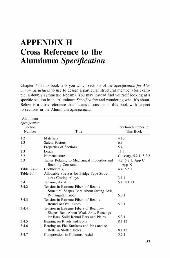
437
APPENDIX HCross Reference to theAluminum Specification
Chapter 7 of this book tells you which sections of the Specification for Alu-minum Structures to use to design a particular structural member (for exam-ple, a doubly symmetric I-beam). You may instead find yourself looking at aspecific section in the Aluminum Specification and wondering what it’s about.Below is a cross reference that locates discussion in this book with respectto sections in the Aluminum Specification.
AluminumSpecification
SectionNumber Title
Section Number inThis Book
1.2 Materials 4.101.3 Safety Factors 6.32.1 Properties of Sections 5.42.3 Loads 11.33.2 Nomenclature Glossary, 5.2.1, 5.2.23.3 Tables Relating to Mechanical Properties and
Buckling Constants4.2, 5.2.1, App C,
App KTable 3.4-2 Coefficient kt 4.4, 5.5.1Table 3.4-4 Allowable Stresses for Bridge Type Struc-
tures Casting Alloys 3.1.43.4.1 Tension, Axial 5.1, 8.1.133.4.2 Tension in Extreme Fibers of Beams—
Structural Shapes Bent About Strong Axis,Rectangular Tubes 5.3.1
3.4.3 Tension in Extreme Fibers of Beams—Round or Oval Tubes 5.3.1
3.4.4 Tension in Extreme Fibers of Beams—Shapes Bent About Weak Axis, Rectangu-lar Bars, Solid Round Bars and Plates 5.3.1
3.4.5 Bearing on Rivets and Bolts 8.1.123.4.6 Bearing on Flat Surfaces and Pins and on
Bolts in Slotted Holes 8.1.123.4.7 Compression in Columns, Axial 5.2.1
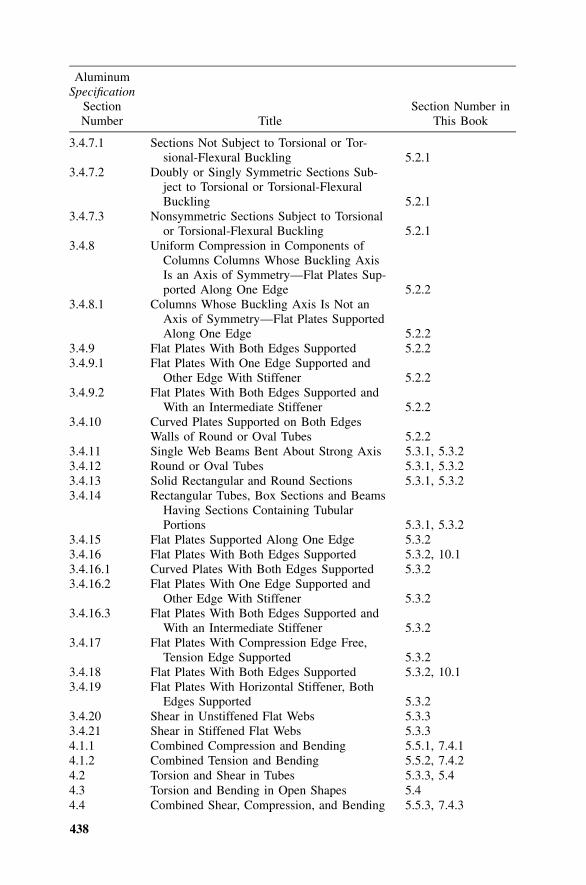
438
AluminumSpecification
SectionNumber Title
Section Number inThis Book
3.4.7.1 Sections Not Subject to Torsional or Tor-sional-Flexural Buckling 5.2.1
3.4.7.2 Doubly or Singly Symmetric Sections Sub-ject to Torsional or Torsional-FlexuralBuckling 5.2.1
3.4.7.3 Nonsymmetric Sections Subject to Torsionalor Torsional-Flexural Buckling 5.2.1
3.4.8 Uniform Compression in Components ofColumns Columns Whose Buckling AxisIs an Axis of Symmetry—Flat Plates Sup-ported Along One Edge 5.2.2
3.4.8.1 Columns Whose Buckling Axis Is Not anAxis of Symmetry—Flat Plates SupportedAlong One Edge 5.2.2
3.4.9 Flat Plates With Both Edges Supported 5.2.23.4.9.1 Flat Plates With One Edge Supported and
Other Edge With Stiffener 5.2.23.4.9.2 Flat Plates With Both Edges Supported and
With an Intermediate Stiffener 5.2.23.4.10 Curved Plates Supported on Both Edges
Walls of Round or Oval Tubes 5.2.23.4.11 Single Web Beams Bent About Strong Axis 5.3.1, 5.3.23.4.12 Round or Oval Tubes 5.3.1, 5.3.23.4.13 Solid Rectangular and Round Sections 5.3.1, 5.3.23.4.14 Rectangular Tubes, Box Sections and Beams
Having Sections Containing TubularPortions 5.3.1, 5.3.2
3.4.15 Flat Plates Supported Along One Edge 5.3.23.4.16 Flat Plates With Both Edges Supported 5.3.2, 10.13.4.16.1 Curved Plates With Both Edges Supported 5.3.23.4.16.2 Flat Plates With One Edge Supported and
Other Edge With Stiffener 5.3.23.4.16.3 Flat Plates With Both Edges Supported and
With an Intermediate Stiffener 5.3.23.4.17 Flat Plates With Compression Edge Free,
Tension Edge Supported 5.3.23.4.18 Flat Plates With Both Edges Supported 5.3.2, 10.13.4.19 Flat Plates With Horizontal Stiffener, Both
Edges Supported 5.3.23.4.20 Shear in Unstiffened Flat Webs 5.3.33.4.21 Shear in Stiffened Flat Webs 5.3.34.1.1 Combined Compression and Bending 5.5.1, 7.4.14.1.2 Combined Tension and Bending 5.5.2, 7.4.24.2 Torsion and Shear in Tubes 5.3.3, 5.44.3 Torsion and Bending in Open Shapes 5.44.4 Combined Shear, Compression, and Bending 5.5.3, 7.4.3
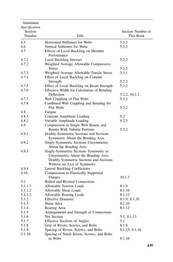
439
AluminumSpecification
SectionNumber Title
Section Number inThis Book
4.5 Horizontal Stiffeners for Webs 5.3.24.6 Vertical Stiffeners for Webs 5.3.24.7 Effects of Local Buckling on Member
Performance4.7.1 Local Buckling Stresses 5.2.24.7.2 Weighted Average Allowable Compressive
Stress 5.2.24.7.3 Weighted Average Allowable Tensile Stress 5.3.14.7.4 Effect of Local Buckling on Column
Strength 5.2.24.7.5 Effect of Local Buckling on Beam Strength 5.3.24.7.6 Effective Width for Calculation of Bending
Deflection 5.2.2, 10.1.24.7.7 Web Crippling of Flat Webs 5.3.24.7.8 Combined Web Crippling and Bending for
Flat Webs 5.3.24.8 Fatigue4.8.1 Constant Amplitude Loading 9.24.8.2 Variable Amplitude Loading 9.2.34.9 Compression in Single Web Beams and
Beams With Tubular Portions 5.3.24.9.1 Doubly-Symmetric Sections and Sections
Symmetric About the Bending Axis4.9.2 Singly-Symmetric Sections Unsymmetric
About the Bending Axis4.9.3 Singly-Symmetric Sections Symmetric or
Unsymmetric About the Bending Axis,Doubly-Symmetric Sections and SectionsWithout an Axis of Symmetry
4.9.4 Lateral Buckling Coefficients4.10 Compression in Elastically Supported
Flanges 10.1.35.1 Bolted and Riveted Connections5.1.1.1 Allowable Tension Loads 8.1.95.1.1.2 Allowable Shear Loads 8.1.105.1.1.3 Allowable Bearing Loads 8.1.125.1.2 Effective Diameter 8.1.9, 8.1.105.1.3 Shear Area 8.1.105.1.4 Bearing Area 8.1.125.1.5 Arrangements and Strength of Connections5.1.6 Net Section 5.1, 8.1.135.1.7 Effective Sections of Angles 5.15.1.8 Grip of Rivets, Screws, and Bolts 8.1.85.1.9 Spacing of Rivets, Screws, and Bolts 8.1.15, 8.1.165.1.10 Spacing of Stitch Rivets, Screws, and Bolts
in Webs 8.1.16

440
AluminumSpecification
SectionNumber Title
Section Number inThis Book
5.1.11 Edge Distance of Rivets, Screws, or Bolts 8.1.12, 8.1.155.1.12 Blind Rivets 8.1.25.1.13 Hollow-End (Semi-Tubular) Rivets5.1.14 Steel Rivets 8.1.35.1.15 Lockbolts 3.3, 8.1.25.1.16 Steel Bolts 8.1.2, 8.1.35.1.17 Slip-Critical Connections 8.1.65.2 Metal Stitching Staples5.3 Tapping Screw Connections 8.1.175.3.1 Shear 8.1.175.3.2 Tension 8.1.175.4 Block Shear Rupture 8.1.145.5 Laps in Building Sheathing5.5.1 Endlaps 10.1.15.5.2 Sidelaps 10.1.15.5.3 Fasteners in Laps 10.1.15.6 Flashing and Closures6.1 Laying Out 3.3, 4.96.2 Cutting 3.1.26.3 Heating 3.1.2, 4.6, 8.2.56.4 Punching, Drilling, and Reaming 8.1.76.5 Riveting 8.1.26.6 Painting 3.2.3, 10.3.36.7 Cleaning and Treatment of Metal Surfaces 3.2.47.1 Allowable Stresses for Welded Members 9.17.1.1 General 9.17.1.2 Members With Part of the Cross Section
Weld-Affected 9.17.1.3 Columns or Beams with Transverse Welds
Away from Supports and Cantilevers withTransverse Welds 9.1
7.2 Filler Wire 8.2.27.3 Welding Fabrication 8.2.57.4 Post-Weld Heat Treating 9.1.58.3.1 Tests for Determining Mechanical Properties Appendix M8.4.4 Allowable Deflections 3.1.5, 10.1.1
441
APPENDIX ILRFD Design Stresses for VariousAlloys
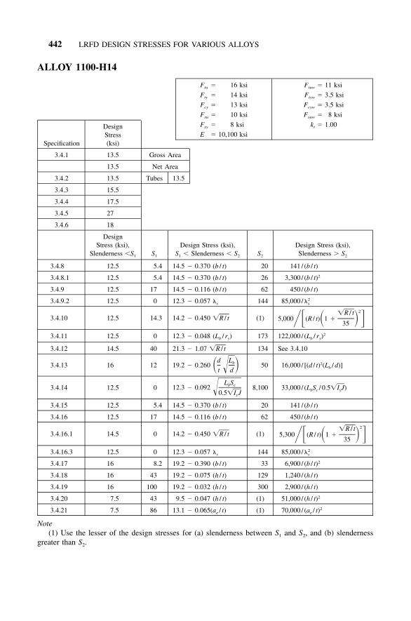
442 LRFD DESIGN STRESSES FOR VARIOUS ALLOYS
ALLOY 1100-H14
F � 16 ksitu
F � 14 ksity
F � 13 ksicy
F � 10 ksisu
F � 8 ksisy
E � 10,100 ksi
F � 11 ksituw
F � 3.5 ksityw
F � 3.5 ksicyw
F � 8 ksisuw
k � 1.00t
Specification
DesignStress(ksi)
3.4.1 13.5 Gross Area
13.5 Net Area
3.4.2 13.5 Tubes 13.5
3.4.3 15.5
3.4.4 17.5
3.4.5 27
3.4.6 18
DesignStress (ksi),
Slenderness �S1 S1
Design Stress (ksi),S1 � Slenderness � S2 S2
Design Stress (ksi),Slenderness � S2
3.4.8 12.5 5.4 14.5 � 0.370 (b / t) 20 141 / (b / t)
3.4.8.1 12.5 5.4 14.5 � 0.370 (b / t) 26 3,300 / (b / t)2
3.4.9 12.5 17 14.5 � 0.116 (b / t) 62 450 / (b / t)
3.4.9.2 12.5 0 12.3 � 0.057 �s 144 85,000 / 2�s
3.4.10 12.5 14.3 14.2 � 0.450 �R / t (1)2�R / t
5,000 (R / t) 1 �� � � �35
3.4.11 12.5 0 12.3 � 0.048 (Lb / ry) 173 122,000 / (Lb / ry)2
3.4.12 14.5 40 21.3 � 1.07 �R / t 134 See 3.4.10
3.4.13 16 12 19.2 � 0.260d Lb� ��t d
50 16,000 / [(d / t)2(Lb / d)]
3.4.14 12.5 0 12.3 � 0.092L Sb c�0.5�I Jy
8,100 33,000 / (LbSc / 0.5�I J)y
3.4.15 12.5 5.4 14.5 � 0.370 (b / t) 20 141 / (b / t)
3.4.16 12.5 17 14.5 � 0.116 (b / t) 62 450 / (b / t)
3.4.16.1 14.5 0 14.2 � 0.450 �R / t (1)2�R / t
5,300 (R / t) 1 �� � � �35
3.4.16.3 12.5 0 12.3 � 0.057 �s 144 85,000 / 2�s
3.4.17 16 8.2 19.2 � 0.390 (b / t) 33 6,900 / (b / t)2
3.4.18 16 43 19.2 � 0.075 (h / t) 129 1,240 / (h / t)
3.4.19 16 100 19.2 � 0.032 (h / t) 300 2,900 / (h / t)
3.4.20 7.5 43 9.5 � 0.047 (h / t) (1) 51,000 / (h / t)2
3.4.21 7.5 86 13.1 � 0.065(ae / t) (1) 70,000 / (ae / t)2
Note(1) Use the lesser of the design stresses for (a) slenderness between S1 and S2, and (b) slenderness
greater than S2.
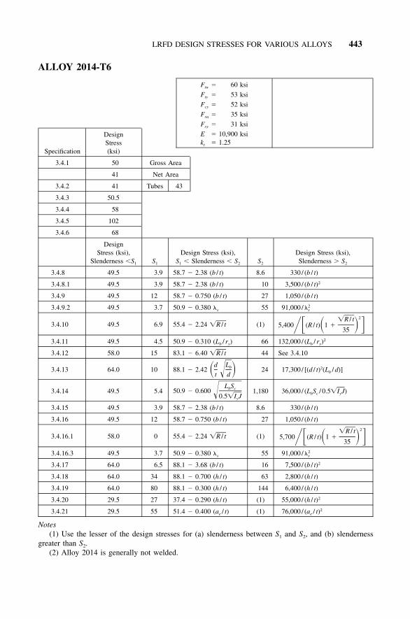
LRFD DESIGN STRESSES FOR VARIOUS ALLOYS 443
ALLOY 2014-T6
F � 60 ksitu
F � 53 ksity
F � 52 ksicy
F � 35 ksisu
F � 31 ksisy
E � 10,900 ksik � 1.25t
Specification
DesignStress(ksi)
3.4.1 50 Gross Area
41 Net Area
3.4.2 41 Tubes 43
3.4.3 50.5
3.4.4 58
3.4.5 102
3.4.6 68
DesignStress (ksi),
Slenderness �S1 S1
Design Stress (ksi),S1 � Slenderness � S2 S2
Design Stress (ksi),Slenderness � S2
3.4.8 49.5 3.9 58.7 � 2.38 (b / t) 8.6 330 / (b / t)
3.4.8.1 49.5 3.9 58.7 � 2.38 (b / t) 10 3,500 / (b / t)2
3.4.9 49.5 12 58.7 � 0.750 (b / t) 27 1,050 / (b / t)
3.4.9.2 49.5 3.7 50.9 � 0.380 �s 55 91,000 / 2�s
3.4.10 49.5 6.9 55.4 � 2.24 �R / t (1)2�R / t
5,400 (R / t) 1 �� � � �35
3.4.11 49.5 4.5 50.9 � 0.310 (Lb / ry) 66 132,000 / (Lb / ry)2
3.4.12 58.0 15 83.1 � 6.40 �R / t 44 See 3.4.10
3.4.13 64.0 10 88.1 � 2.42d Lb� ��t d
24 17,300 / [(d / t)2(Lb / d)]
3.4.14 49.5 5.4 50.9 � 0.600L Sb c�0.5�I Jy
1,180 36,000 / (LbSc / 0.5�I J)y
3.4.15 49.5 3.9 58.7 � 2.38 (b / t) 8.6 330 / (b / t)
3.4.16 49.5 12 58.7 � 0.750 (b / t) 27 1,050 / (b / t)
3.4.16.1 58.0 0 55.4 � 2.24 �R / t (1)2�R / t
5,700 (R / t) 1 �� � � �35
3.4.16.3 49.5 3.7 50.9 � 0.380 �s 55 91,000 / 2�s
3.4.17 64.0 6.5 88.1 � 3.68 (b / t) 16 7,500 / (b / t)2
3.4.18 64.0 34 88.1 � 0.700 (h / t) 63 2,800 / (h / t)
3.4.19 64.0 80 88.1 � 0.300 (h / t) 144 6,400 / (h / t)
3.4.20 29.5 27 37.4 � 0.290 (h / t) (1) 55,000 / (h / t)2
3.4.21 29.5 55 51.4 � 0.400 (ae / t) (1) 76,000 / (ae / t)2
Notes(1) Use the lesser of the design stresses for (a) slenderness between S1 and S2, and (b) slenderness
greater than S2.(2) Alloy 2014 is generally not welded.
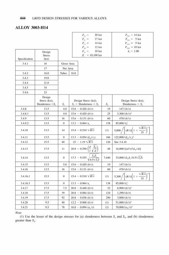
444 LRFD DESIGN STRESSES FOR VARIOUS ALLOYS
ALLOY 3003-H14
F � 20 ksitu
F � 17 ksity
F � 14 ksicy
F � 12 ksisu
F � 10 ksisy
E � 10,100 ksi
F � 14 ksituw
F � 5 ksityw
F � 5 ksicyw
F � 10 ksisuw
k � 1.00t
Specification
DesignStress(ksi)
3.4.1 16 Gross Area
17 Net Area
3.4.2 16.0 Tubes 16.0
3.4.3 19.0
3.4.4 21.0
3.4.5 34
3.4.6 23
DesignStress (ksi),
Slenderness �S1 S1
Design Stress (ksi),S1 � Slenderness � S2 S2
Design Stress (ksi),Slenderness � S2
3.4.8 13.5 4.0 15.6 � 0.420 (b / t) 19 147 / (b / t)
3.4.8.1 13.5 4.0 15.6 � 0.420 (b / t) 25 3,300 / (b / t)2
3.4.9 13.5 16 15.6 � 0.131 (b / t) 60 470 / (b / t)
3.4.9.2 13.5 0 13.3 � 0.064 �s 138 85,000 / 2�s
3.4.10 13.5 14 15.4 � 0.510 �R / t (1)2�R / t
5,000 (R / t) 1 �� � � �35
3.4.11 13.5 0 13.3 � 0.054 (Lb / ry) 166 122,000 / (Lb / ry)2
3.4.12 15.5 40 23 � 1.19 �R / t 126 See 3.4.10
3.4.13 17.5 11 20.8 � 0.290d Lb� ��t d
48 16,000 / [(d / t)2(Lb / d)]
3.4.14 13.5 0 13.3 � 0.103L Sb c�0.5�I Jy
7,440 33,000 / (LbSc / 0.5�I J)y
3.4.15 13.5 5.0 15.6 � 0.420 (b / t) 19 147 / (b / t)
3.4.16 13.5 16 15.6 � 0.131 (b / t) 60 470 / (b / t)
3.4.16.1 15.5 0 15.4 � 0.510 �R / t (1)2�R / t
5,300 (R / t) 1 �� � � �35
3.4.16.3 13.5 0 13.3 � 0.064 �s 138 85,000 / 2�s
3.4.17 17.5 7.5 20.8 � 0.440 (b / t) 32 6,900 / (b / t)2
3.4.18 17.5 39 20.8 � 0.084 (h / t) 124 1,290 / (h / t)
3.4.19 17.5 92 20.8 � 0.036 (h / t) 290 3,000 / (h / t)
3.4.20 9.5 40 12.2 � 0.068 (h / t) (1) 51,000 / (h / t)2
3.4.21 9.5 78 16.8 � 0.094 (ae / t) (1) 70,000 / (ae / t)2
Note(1) Use the lesser of the design stresses for (a) slenderness between S1 and S2, and (b) slenderness
greater than S2.
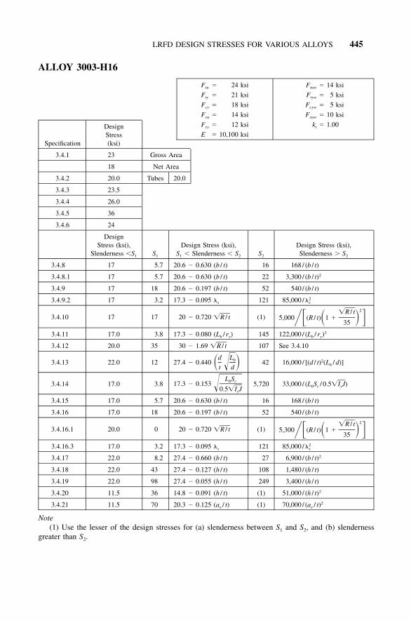
LRFD DESIGN STRESSES FOR VARIOUS ALLOYS 445
ALLOY 3003-H16
F � 24 ksitu
F � 21 ksity
F � 18 ksicy
F � 14 ksisu
F � 12 ksisy
E � 10,100 ksi
F � 14 ksituw
F � 5 ksityw
F � 5 ksicyw
F � 10 ksisuw
k � 1.00t
Specification
DesignStress(ksi)
3.4.1 23 Gross Area
18 Net Area
3.4.2 20.0 Tubes 20.0
3.4.3 23.5
3.4.4 26.0
3.4.5 36
3.4.6 24
DesignStress (ksi),
Slenderness �S1 S1
Design Stress (ksi),S1 � Slenderness � S2 S2
Design Stress (ksi),Slenderness � S2
3.4.8 17 5.7 20.6 � 0.630 (b / t) 16 168 / (b / t)
3.4.8.1 17 5.7 20.6 � 0.630 (b / t) 22 3,300 / (b / t)2
3.4.9 17 18 20.6 � 0.197 (b / t) 52 540 / (b / t)
3.4.9.2 17 3.2 17.3 � 0.095 �s 121 85,000 / 2�s
3.4.10 17 17 20 � 0.720 �R / t (1)2�R / t
5,000 (R / t) 1 �� � � �35
3.4.11 17.0 3.8 17.3 � 0.080 (Lb / ry) 145 122,000 / (Lb / ry)2
3.4.12 20.0 35 30 � 1.69 �R / t 107 See 3.4.10
3.4.13 22.0 12 27.4 � 0.440d Lb� ��t d
42 16,000 / [(d / t)2(Lb / d)]
3.4.14 17.0 3.8 17.3 � 0.153L Sb c�0.5�I Jy
5,720 33,000 / (LbSc / 0.5�I J)y
3.4.15 17.0 5.7 20.6 � 0.630 (b / t) 16 168 / (b / t)
3.4.16 17.0 18 20.6 � 0.197 (b / t) 52 540 / (b / t)
3.4.16.1 20.0 0 20 � 0.720 �R / t (1)2�R / t
5,300 (R / t) 1 �� � � �35
3.4.16.3 17.0 3.2 17.3 � 0.095 �s 121 85,000 / 2�s
3.4.17 22.0 8.2 27.4 � 0.660 (b / t) 27 6,900 / (b / t)2
3.4.18 22.0 43 27.4 � 0.127 (h / t) 108 1,480 / (h / t)
3.4.19 22.0 98 27.4 � 0.055 (h / t) 249 3,400 / (h / t)
3.4.20 11.5 36 14.8 � 0.091 (h / t) (1) 51,000 / (h / t)2
3.4.21 11.5 70 20.3 � 0.125 (ae / t) (1) 70,000 / (ae / t)2
Note(1) Use the lesser of the design stresses for (a) slenderness between S1 and S2, and (b) slenderness
greater than S2.

446 LRFD DESIGN STRESSES FOR VARIOUS ALLOYS
ALLOY 3004-H16 Alclad
F � 35 ksitu
F � 30 ksity
F � 28 ksicy
F � 20 ksisu
F � 17 ksisy
E � 10,100 ksi
F � 21 ksituw
F � 8 ksityw
F � 8 ksicyw
F � 13 ksisuw
k � 1.00t
Specification
DesignStress(ksi)
3.4.1 29 Gross Area
30 Net Area
3.4.2 28.5 Tubes 28.5
3.4.3 33.5
3.4.4 37.0
3.4.5 60
3.4.6 40
Design Stress(ksi),
Slenderness �S1 S1
Design Stress (ksi),S1 � Slenderness � S2 S2
Design Stress (ksi),Slenderness � S2
3.4.8 26.5 5.2 33.3 � 1.300 (b / t) 13 210 / (b / t)
3.4.8.1 26.5 5.2 33.3 � 1.30 (b / t) 17 3,300 / (b / t)2
3.4.9 26.5 17 33.3 � 0.410 (b / t) 41 680 / (b / t)
3.4.9.2 26.5 6.2 27.8 � 0.194 �s 96 85,000 / 2�s
3.4.10 26.5 16 31.8 � 1.33 �R / t (1)2�R / t
5,000 (R / t) 1 �� � � �35
3.4.11 26.5 8.1 27.8 � 0.161 (Lb / ry) 115 122,000 / (Lb / ry)2
3.4.12 31.0 28 47.7 � 3.13 �R / t 78 See 3.4.10
3.4.13 34.5 11 44.4 � 0.900d Lb� ��t d
33 16,000 / [(d / t)2(Lb / d)]
3.4.14 26.5 18 27.8 � 0.310L Sb c�0.5�I Jy
3,600 33,000 / (LbSc / 0.5�I J)y
3.4.15 26.5 5.2 33.3 � 1.30 (b / t) 13 210 / (b / t)
3.4.16 26.5 17 33.3 � 0.410 (b / t) 41 680 / (b / t)
3.4.16.1 31.0 0.4 31.8 � 1.33 �R / t (1)2�R / t
5,300 (R / t) 1 �� � � �35
3.4.16.3 26.5 6.7 27.8 � 0.194 �s 96 85,000 / 2�s
3.4.17 34.5 7.2 44.4 � 1.37 (b / t) 22 6,900 / (b / t)2
3.4.18 34.5 38 44.4 � 0.260 (h / t) 85 1,880 / (h / t)
3.4.19 34.5 88 44.4 � 0.113 (h / t) 196 4,300 / (h / t)
3.4.20 16.0 35 21.7 � 0.162 (h / t) (1) 51,000 / (h / t)2
3.4.21 16.0 63 29.8 � 0.220 (ae / t) (1) 70,000 / (ae / t)2
Note(1) Use the lesser of the design stresses for (a) slenderness between S1 and S2 and (b) slenderness
greater than S2.

LRFD DESIGN STRESSES FOR VARIOUS ALLOYS 447
ALLOY 3004-H34 Alclad
F � 31 ksitu
F � 24 ksity
F � 21 ksicy
F � 18 ksisu
F � 14 ksisy
E � 10,100 ksi
F � 21 ksituw
F � 8 ksityw
F � 8 ksicyw
F � 13 ksisuw
k � 1.00t
Specification
DesignStress(ksi)
3.4.1 23 Gross Area
26 Net Area
3.4.2 23.0 Tubes 23.0
3.4.3 26.5
3.4.4 29.5
3.4.5 53
3.4.6 35
Design Stress(ksi),
Slenderness �S1 S1
Design Stress (ksi),S1 � Slenderness � S2 S2
Design Stress (ksi),Slenderness � S2
3.4.8 20 5.3 24.3 � 0.810 (b / t) 15 183 / (b / t)
3.4.8.1 20 5.3 24.3 � 0.810 (b / t) 20 3,300 / (b / t)2
3.4.9 20 17 24.3 � 0.250 (b / t) 48 580 / (b / t)
3.4.9.2 20 3.3 20.4 � 0.122 �s 112 85,000 / 2�s
3.4.10 20 15 23.5 � 0.890 �R / t (1)2�R / t
5,000 (R / t) 1 �� � � �35
3.4.11 20.0 4 20.4 � 0.101 (Lb / ry) 134 122,000 / (Lb / ry)2
3.4.12 23.5 32 35.3 � 2.09 �R / t 95 See 3.4.10
3.4.13 26.0 11 32.4 � 0.560d Lb� ��t d
39 16,000 / [(d / t)2(Lb / d)]
3.4.14 20.0 4.2 20.4 � 0.195L Sb c�0.5�I Jy
4,900 33,000 / (LbSc / 0.5�I J)y
3.4.15 20.0 5.3 24.3 � 0.810 (b / t) 15 183 / (b / t)
3.4.16 20.0 17 24.3 � 0.250 (b / t) 48 580 / (b / t)
3.4.16.1 23.5 0 23.5 � 0.890 �R / t (1)2�R / t
5,300 (R / t) 1 �� � � �35
3.4.16.3 20.0 3.3 20.4 � 0.122 �s 112 85,000 / 2�s
3.4.17 26.0 7.5 32.4 � 0.850 (b / t) 25 6,900 / (b / t)2
3.4.18 26.0 39 32.4 � 0.163 (h / t) 99 1,610 / (h / t)
3.4.19 26.0 90 32.4 � 0.071 (h / t) 229 3,700 / (h / t)
3.4.20 13.5 34 17.5 � 0.117 (h / t) (1) 51,000 / (h / t)2
3.4.21 13.5 66 24.1 � 0.161(ae / t) (1) 70,000 / (ae / t)2
Note(1) Use the lesser of the design stresses for (a) slenderness between S1 and S2, and (b) slenderness
greater than S2.

448 LRFD DESIGN STRESSES FOR VARIOUS ALLOYS
ALLOY 5005-H14
F � 21 ksitu
F � 17 ksity
F � 15 ksicy
F � 12 ksisu
F � 10 ksisy
E � 10,100 ksi
F � 15 ksituw
F � 5 ksityw
F � 5 ksicyw
F � 9 ksisuw
k � 1.00t
Specification
DesignStress(ksi)
3.4.1 16 Gross Area
18 Net Area
3.4.2 16.0 Tubes 16.0
3.4.3 19.0
3.4.4 21.0
3.4.5 36
3.4.6 24
DesignStress (ksi),
Slenderness �S1 S1
Design Stress (ksi),S1 � Slenderness � S2 S2
Design Stress (ksi),Slenderness � S2
3.4.8 14 6.2 16.9 � 0.470 (b / t) 18 152 / (b / t)
3.4.8.1 14 6.2 16.9 � 0.470 (b / t) 24 3,300 / (b / t)2
3.4.9 14 20 16.9 � 0.147 (b / t) 57 490 / (b / t)
3.4.9.2 14 4.2 14.3 � 0.071 �s 133 85,000 / 2�s
3.4.10 14 21 16.5 � 0.550 �R / t (1)2�R / t
5,000 (R / t) 1 �� � � �35
3.4.11 14.0 5.1 14.3 � 0.059 (Lb / ry) 160 122,000 / (Lb / ry)2
3.4.12 16.5 40 24.8 � 1.31 �R / t 122 See 3.4.10
3.4.13 18.5 12 22.4 � 0.320d Lb� ��t d
46 16,000 / [(d / t)2(Lb / d)]
3.4.14 14.0 6.9 14.3 � 0.114L Sb c�0.5�I Jy
6,910 33,000 / (LbSc / 0.5�I J)y
3.4.15 14.0 6.2 16.9 � 0.470 (b / t) 18 152 / (b / t)
3.4.16 14.0 20 16.9 � 0.147 (b / t) 57 490 / (b / t)
3.4.16.1 16.5 0 16.5 � 0.550 �R / t (1)2�R / t
5,300 (R / t) 1 �� � � �35
3.4.16.3 14.0 4.2 14.3 � 0.071 �s 133 85,000 / 2�s
3.4.17 18.5 8.0 22.4 � 0.490 (b / t) 30 6,900 / (b / t)2
3.4.18 18.5 41 22.4 � 0.094 (h / t) 119 1,340 / (h / t)
3.4.19 18.5 95 22.4 � 0.041 (h / t) 280 3,100 / (h / t)
3.4.20 9.5 40 12.2 � 0.068 (h / t) (1) 51,000 / (h / t)2
3.4.21 9.5 78 16.8 � 0.094 (ae / t) (1) 70,000 / (ae / t)2
Note(1) Use the lesser of the design stresses for (a) slenderness between S1 and S2, and (b) slenderness
greater than S2.

LRFD DESIGN STRESSES FOR VARIOUS ALLOYS 449
ALLOY 5050-H34
F � 25 ksitu
F � 20 ksity
F � 18 ksicy
F � 15 ksisu
F � 12 ksisy
E � 10,100 ksi
F � 18 ksituw
F � 6 ksityw
F � 6 ksicyw
F � 12 ksisuw
k � 1.00t
Specification
DesignStress(ksi)
3.4.1 19 Gross Area
21 Net Area
3.4.2 19.0 Tubes 19.0
3.4.3 22.0
3.4.4 24.5
3.4.5 43
3.4.6 28
DesignStress (ksi),
Slenderness �S1 S1
Design Stress (ksi),S1 � Slenderness � S2 S2
Design Stress (ksi),Slenderness � S2
3.4.8 17 5.7 20.6 � 0.630 (b / t) 16 168 / (b / t)
3.4.8.1 17 5.7 20.6 � 0.630 (b / t) 22 3,300 / (b / t)2
3.4.9 17 18 20.6 � 0.197 (b / t) 52 540 / (b / t)
3.4.9.2 17 3.2 17.3 � 0.095 �s 121 85,000 / 2�s
3.4.10 17 17 20 � 0.720 �R / t (1)2�R / t
5,000 (R / t) 1 �� � � �35
3.4.11 17.0 3.8 17.3 � 0.080 (Lb / ry) 145 122,000 / (Lb / ry)2
3.4.12 20.0 35 30 � 1.69 �R / t 107 See 3.4.10
3.4.13 22.0 12 27.4 � 0.440d Lb� ��t d
42 16,000 / [(d / t)2(Lb / d)]
3.4.14 17.0 3.8 17.3 � 0.153L Sb c�0.5�I Jy
5,720 33,000 / (LbSc / 0.5�I J)y
3.4.15 17.0 5.7 20.6 � 0.630 (b / t) 16 168 / (b / t)
3.4.16 17.0 18 20.6 � 0.197 (b / t) 52 540 / (b / t)
3.4.16.1 20.0 0 20 � 0.720 �R / t (1)2�R / t
5,300 (R / t) 1 �� � � �35
3.4.16.3 17.0 3.2 17.3 � 0.095 �s 121 85,000 / 2�s
3.4.17 22.0 8.2 27.4 � 0.660 (b / t) 27 6.900 / (b / t)2
3.4.18 22.0 43 27.4 � 0.127 (h / t) 108 1,480 / (h / t)
3.4.19 22.0 98 27.4 � 0.055 (h / t) 249 3,400 / (h / t)
3.4.20 11.5 36 14.8 � 0.091 (h / t) (1) 51,000 / (h / t)2
3.4.21 11.5 70 20.3 � 0.125 (ae / t) (1) 70,000 / (ae / t)2
Note(1) Use the lesser of the design stresses for (a) slenderness between S1 and S2, and (b) slenderness
greater than S2.

450 LRFD DESIGN STRESSES FOR VARIOUS ALLOYS
ALLOY 5052-H34
F � 34 ksitu
F � 26 ksity
F � 24 ksicy
F � 20 ksisu
F � 15 ksisy
E � 10,200 ksi
F � 25 ksituw
F � 9.5 ksityw
F � 9.5 ksicyw
F � 16 ksisuw
k � 1.00t
Specification
DesignStress(ksi)
3.4.1 25 Gross Area
29 Net Area
3.4.2 24.5 Tubes 24.5
3.4.3 29.0
3.4.4 32.0
3.4.5 58
3.4.6 39
DesignStress (ksi),
Slenderness �S1 S1
Design Stress (ksi),S1 � Slenderness � S2 S2
Design Stress (ksi),Slenderness � S2
3.4.8 23 5.1 28.1 � 1.00 (b / t) 14 198 / (b / t)
3.4.8.1 23 5.1 28.1 � 1.00 (b / t) 19 3,300 / (b / t)2
3.4.9 23 16 28.1 � 0.310 (b / t) 45 630 / (b / t)
3.4.9.2 23 3.3 23.5 � 0.150 �s 104 86,000 / 2�s
3.4.10 23 14 27 � 1.07 �R / t (1)2�R / t
5,000 (R / t) 1 �� � � �35
3.4.11 23.0 4.0 23.5 � 0.125 (Lb / ry) 125 123,000 / (Lb / ry)2
3.4.12 26.5 31 40.5 � 2.51 �R / t 88 See 3.4.10
3.4.13 29.5 12 37.5 � 0.690d Lb� ��t d
36 16,200 / [(d / t)2(Lb / d)]
3.4.14 23.0 4.3 23.5 � 0.240L Sb c�0.5�I Jy
4,230 33,000 / (LbSc / 0.5�I J)y
3.4.15 23.0 5.1 28.1 � 1.00 (b / t) 14 198 / (b / t)
3.4.16 23.0 16 28.1 � 0.310 (b / t) 45 630 / (b / t)
3.4.16.1 26.5 0.2 27 � 1.07 �R / t (1)2�R / t
5,300 (R / t) 1 �� � � �35
3.4.16.3 23.0 3.3 23.5 � 0.150 �s 104 86,000 / 2�s
3.4.17 29.5 7.5 37.5 � 1.06 (b / t) 24 7,000 / (b / t)2
3.4.18 29.5 40 37.5 � 0.200 (h / t) 93 1,740 / (h / t)
3.4.19 29.5 91 37.5 � 0.088 (h / t) 214 4,000 / (h / t)
3.4.20 14.0 37 18.9 � 0.131 (h / t) (1) 52,000 / (h / t)2
3.4.21 14.0 66 26.0 � 0.181 (ae / t) (1) 71,000 / (ae / t)2
Note(1) Use the lesser of the design stresses for (a) slenderness between S1 and S2, and (b) slenderness
greater than S2.

LRFD DESIGN STRESSES FOR VARIOUS ALLOYS 451
ALLOY 5083-H111
F � 40 ksitu
F � 24 ksity
F � 21 ksicy
F � 23 ksisu
F � 14 ksisy
E � 10,400 ksi
F � 39 ksituw
F � 16 ksityw
F � 15 ksicyw
F � 23 ksisuw
k � 1.00t
Specification
DesignStress(ksi)
3.4.1 23 Gross Area
34 Net Area
3.4.2 23.0 Tubes 23.0
3.4.3 26.5
3.4.4 29.5
3.4.5 68
3.4.6 45
DesignStress (ksi),
Slenderness �S1 S1
Design Stress (ksi),S1 � Slenderness � S2 S2
Design Stress (ksi),Slenderness � S2
3.4.8 20 5.4 24.3 � 0.800 (b / t) 15 185 / (b / t)
3.4.8.1 20 5.4 24.3 � 0.800 (b / t) 20 3,400 / (b / t)2
3.4.9 20 17 24.3 � 0.250 (b / t) 49 590 / (b / t)
3.4.9.2 20 3.3 20.4 � 0.120 �s 113 87,000 / 2�s
3.4.10 20 16 23.5 � 0.880 �R / t (1)2�R / t
5,100 (R / t) 1 �� � � �35
3.4.11 20.0 4.0 20.4 � 0.100 (Lb / ry) 136 126,000 / (Lb / ry)2
3.4.12 23.5 32 35.3 � 2.07 �R / t 97 See 3.4.10
3.4.13 26.0 12 32.4 � 0.550d Lb� ��t d
39 16,500 / [(d / t)2(Lb / d)]
3.4.14 20.0 4.3 20.4 � 0.192L Sb c�0.5�I Jy
4,990 34,000 / (LbSc / 0.5�I J)y
3.4.15 20.0 5.4 24.3 � 0.800 (b / t) 15 185 / (b / t)
3.4.16 20.0 17 24.3 � 0.250 (b / t) 49 590 / (b / t)
3.4.16.1 23.5 0 23.5 � 0.880 �R / t (1)2�R / t
5,500 (R / t) 1 �� � � �35
3.4.16.3 20.0 3.3 20.4 � 0.120 �s 113 87,000 / 2�s
3.4.17 26.0 7.6 32.4 � 0.840 (b / t) 26 7,100 / (b / t)2
3.4.18 26.0 40 32.4 � 0.161 (h / t) 101 1,630 / (h / t)
3.4.19 26.0 91 32.4 � 0.070 (h / t) 233 3,800 / (h / t)
3.4.20 13.5 35 17.5 � 0.115 (h / t) (1) 53,000 / (h / t)2
3.4.21 13.5 67 24.1 � 0.159 (ae / t) (1) 72,000 / (ae / t)2
Note(1) Use the lesser of the design stresses for (a) slenderness between S1 and S2, and (b) slenderness
greater than S2.
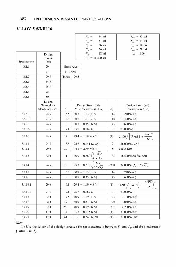
452 LRFD DESIGN STRESSES FOR VARIOUS ALLOYS
ALLOY 5083-H116
F � 44 ksitu
F � 31 ksity
F � 26 ksicy
F � 26 ksisu
F � 18 ksisy
E � 10,400 ksi
F � 40 ksituw
F � 14 ksityw
F � 14 ksicyw
F � 21 ksisuw
k � 1.00t
Specification
DesignStress(ksi)
3.4.1 29 Gross Area
37 Net Area
3.4.2 29.5 Tubes 29.5
3.4.3 34.5
3.4.4 38.5
3.4.5 75
3.4.6 50
DesignStress (ksi),
Slenderness �S1 S1
Design Stress (ksi),S1 � Slenderness � S2 S2
Design Stress (ksi),Slenderness � S2
3.4.8 24.5 5.5 30.7 � 1.13 (b / t) 14 210 / (b / t)
3.4.8.1 24.5 5.5 30.7 � 1.13 (b / t) 18 3,400 / (b / t)2
3.4.9 24.5 18 30.7 � 0.350 (b / t) 43 660 / (b / t)
3.4.9.2 24.5 7.1 25.7 � 0.169 �s 101 87,000 / 2�s
3.4.10 24.5 17 29.4 � 1.19 �R / t (1)2�R / t
5,100 (R / t) 1 �� � � �35
3.4.11 24.5 8.5 25.7 � 0.141 (Lb / ry) 121 126,000 / (Lb / ry)2
3.4.12 29.0 29 44.1 � 2.79 �R / t 84 See 3.4.10
3.4.13 32.0 11 40.9 � 0.780d Lb� ��t d
35 16,500 / [(d / t)2(Lb / d)]
3.4.14 24.5 20 25.7 � 0.270L Sb c�0.5�I Jy
3,980 34,000 / (LbSc / 0.5�I J)y
3.4.15 24.5 5.5 30.7 � 1.13 (b / t) 14 210 / (b / t)
3.4.16 24.5 18 30.7 � 0.350 (b / t) 43 660 / (b / t)
3.4.16.1 29.0 0.1 29.4 � 1.19 �R / t (1)2�R / t
5,500 (R / t) 1 �� � � �35
3.4.16.3 24.5 7.1 25.7 � 0.169 �s 101 87,000 / 2�s
3.4.17 32.0 7.5 40.9 � 1.19 (b / t) 23 7,100 / (b / t)2
3.4.18 32.0 39 40.9 � 0.230 (h / t) 90 1,830 / (h / t)
3.4.19 32.0 90 40.9 � 0.099 (h / t) 207 4,200 / (h / t)
3.4.20 17.0 34 23 � 0.175 (h / t) (1) 53,000 / (h / t)2
3.4.21 17.0 61 31.6 � 0.240 (ae / t) (1) 72,000 / (ae / t)2
Note(1) Use the lesser of the design stresses for (a) slenderness between S1 and S2, and (b) slenderness
greater than S2.
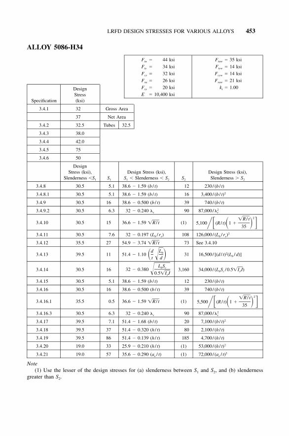
LRFD DESIGN STRESSES FOR VARIOUS ALLOYS 453
ALLOY 5086-H34
F � 44 ksitu
F � 34 ksity
F � 32 ksicy
F � 26 ksisu
F � 20 ksisy
E � 10,400 ksi
F � 35 ksituw
F � 14 ksityw
F � 14 ksicyw
F � 21 ksisuw
k � 1.00t
Specification
DesignStress(ksi)
3.4.1 32 Gross Area
37 Net Area
3.4.2 32.5 Tubes 32.5
3.4.3 38.0
3.4.4 42.0
3.4.5 75
3.4.6 50
DesignStress (ksi),
Slenderness �S1 S1
Design Stress (ksi),S1 � Slenderness � S2 S2
Design Stress (ksi),Slenderness � S2
3.4.8 30.5 5.1 38.6 � 1.59 (b / t) 12 230 / (b / t)
3.4.8.1 30.5 5.1 38.6 � 1.59 (b / t) 16 3,400 / (b / t)2
3.4.9 30.5 16 38.6 � 0.500 (b / t) 39 740 / (b / t)
3.4.9.2 30.5 6.3 32 � 0.240 �s 90 87,000 / 2�s
3.4.10 30.5 15 36.6 � 1.59 �R / t (1)2�R / t
5,100 (R / t) 1 �� � � �35
3.4.11 30.5 7.6 32 � 0.197 (Lb / ry) 108 126,000 / (Lb / ry)2
3.4.12 35.5 27 54.9 � 3.74 �R / t 73 See 3.4.10
3.4.13 39.5 11 51.4 � 1.10d Lb� ��t d
31 16,500 / [(d / t)2(Lb / d)]
3.4.14 30.5 16 32 � 0.380L Sb c�0.5�I Jy
3,160 34,000 / (LbSc / 0.5�I J)y
3.4.15 30.5 5.1 38.6 � 1.59 (b / t) 12 230 / (b / t)
3.4.16 30.5 16 38.6 � 0.500 (b / t) 39 740 / (b / t)
3.4.16.1 35.5 0.5 36.6 � 1.59 �R / t (1)2�R / t
5,500 (R / t) 1 �� � � �35
3.4.16.3 30.5 6.3 32 � 0.240 �s 90 87,000 / 2�s
3.4.17 39.5 7.1 51.4 � 1.68 (b / t) 20 7,100 / (b / t)2
3.4.18 39.5 37 51.4 � 0.320 (h / t) 80 2,100 / (h / t)
3.4.19 39.5 86 51.4 � 0.139 (h / t) 185 4,700 / (h / t)
3.4.20 19.0 33 25.9 � 0.210 (h / t) (1) 53,000 / (h / t)2
3.4.21 19.0 57 35.6 � 0.290 (ae / t) (1) 72,000 / (ae / t)2
Note(1) Use the lesser of the design stresses for (a) slenderness between S1 and S2, and (b) slenderness
greater than S2.

454 LRFD DESIGN STRESSES FOR VARIOUS ALLOYS
ALLOY 5086-H111
F � 36 ksitu
F � 21 ksity
F � 18 ksicy
F � 21 ksisu
F � 12 ksisy
E � 10,400 ksi
F � 35 ksituw
F � 14 ksityw
F � 13 ksicyw
F � 21 ksisuw
k � 1.00t
Specification
DesignStress(ksi)
3.4.1 20 Gross Area
31 Net Area
3.4.2 20.0 Tubes 20.0
3.4.3 23.5
3.4.4 26.0
3.4.5 61
3.4.6 41
DesignStress (ksi),
Slenderness �S1 S1
Design Stress (ksi),S1 � Slenderness � S2 S2
Design Stress (ksi),Slenderness � S2
3.4.8 17 5.8 20.6 � 0.620 (b / t) 17 171 / (b / t)
3.4.8.1 17 5.8 20.6 � 0.620 (b / t) 22 3,400 / (b / t)2
3.4.9 17 19 20.6 � 0.194 (b / t) 53 540 / (b / t)
3.4.9.2 17 3.2 17.3 � 0.094 �s 123 87,000 / 2�s
3.4.10 17 18 20 � 0.710 �R / t (1)2�R / t
5,100 (R / t) 1 �� � � �35
3.4.11 17.0 3.8 17.3 � 0.078 (Lb / ry) 148 126,000 / (Lb / ry)2
3.4.12 20.0 36 30 � 1.67 �R / t 109 See 3.4.10
3.4.13 22.0 13 27.4 � 0.430d Lb� ��t d
43 16,500 / [(d / t)2(Lb / d)]
3.4.14 17.0 4.0 17.3 � 0.150L Sb c�0.5�I Jy
5,910 34,000 / (LbSc / 0.5�I J)y
3.4.15 17.0 5.8 20.6 � 0.620 (b / t) 17 171 / (b / t)
3.4.16 17.0 19 20.6 � 0.194 (b / t) 53 540 / (b / t)
3.4.16.1 20.0 0 20 � 0.710 �R / t (1)2�R / t
5,500 (R / t) 1 �� � � �35
3.4.16.3 17.0 3.2 17.3 � 0.094 �s 123 87,000 / 2�s
3.4.17 22.0 8.3 27.4 � 0.650 (b / t) 28 7,100 / (b / t)2
3.4.18 22.0 43 27.4 � 0.125 (h / t) 110 1,500 / (h / t)
3.4.19 22.0 100 27.4 � 0.054 (h / t) 250 3,500 / (h / t)
3.4.20 11.5 37 14.8 � 0.090 (h / t) (1) 53,000 / (h / t)2
3.4.21 11.5 72 20.3 � 0.123 (ae / t) (1) 72,000 / (ae / t)2
Note(1) Use the lesser of the design stresses for (a) slenderness between S1 and S2, and (b) slenderness
greater than S2.

LRFD DESIGN STRESSES FOR VARIOUS ALLOYS 455
ALLOY 5086-H116
F � 40 ksitu
F � 28 ksity
F � 26 ksicy
F � 24 ksisu
F � 16 ksisy
E � 10,400 ksi
F � 35 ksituw
F � 14 ksityw
F � 14 ksicyw
F � 21 ksisuw
k � 1.00t
Specification
DesignStress(ksi)
3.4.1 27 Gross Area
34 Net Area
3.4.2 26.5 Tubes 26.5
3.4.3 31.0
3.4.4 34.5
3.4.5 68
3.4.6 45
DesignStress (ksi),
Slenderness �S1 S1
Design Stress (ksi),S1 � Slenderness � S2 S2
Design Stress (ksi),Slenderness � S2
3.4.8 24.5 5.5 30.7 � 1.13 (b / t) 14 210 / (b / t)
3.4.8.1 24.5 5.5 30.7 � 1.13 (b / t) 18 3,400 / (b / t)2
3.4.9 24.5 18 30.7 � 0.350 (b / t) 43 660 / (b / t)
3.4.9.2 24.5 7.1 25.7 � 0.169 �s 101 87,000 / 2�s
3.4.10 24.5 17 29.4 � 1.19 �R / t (1)2�R / t
5,100 (R / t) 1 �� � � �35
3.4.11 24.5 8.5 25.7 � 0.141 (Lb / ry) 121 126,000 / (Lb / ry)2
3.4.12 29.0 29 44.1 � 2.79 �R / t 84 See 3.4.10
3.4.13 32.0 11 40.9 � 0.780d Lb� ��t d
35 16,500 / [(d / t)2(Lb / d)]
3.4.14 24.5 20 25.7 � 0.270L Sb c�0.5�I Jy
3,980 34,000 / (LbSc / 0.5�I J)y
3.4.15 24.5 5.5 30.7 � 1.13 (b / t) 14 210 / (b / t)
3.4.16 24.5 18 30.7 � 0.350 (b / t) 43 660 / (b / t)
3.4.16.1 29.0 0.1 29.4 � 1.19 �R / t (1)2�R / t
5,500 (R / t) 1 �� � � �35
3.4.16.3 24.5 7.1 25.7 � 0.169 �s 101 87,000 / 2�s
3.4.17 32.0 7.5 40.9 � 1.19 (b / t) 23 7,100 / (b / t)2
3.4.18 32.0 39 40.9 � 0.230 (h / t) 90 1,830 / (h / t)
3.4.19 32.0 90 40.9 � 0.099 (h / t) 207 4,200 / (h / t)
3.4.20 15.0 37 20.3 � 0.144 (h / t) (1) 53,000 / (h / t)2
3.4.21 15.0 65 27.9 � 0.198 (ae / t) (1) 72,000 / (ae / t)2
Note(1) Use the lesser of the design stresses for (a) slenderness between S1 and S2, and (b) slenderness
greater than S2.
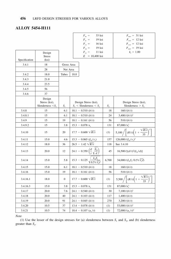
456 LRFD DESIGN STRESSES FOR VARIOUS ALLOYS
ALLOY 5454-H111
F � 33 ksitu
F � 19 ksity
F � 16 ksicy
F � 19 ksisu
F � 11 ksisy
E � 10,400 ksi
F � 31 ksituw
F � 12 ksityw
F � 12 ksicyw
F � 19 ksisuw
k � 1.00t
Specification
DesignStress(ksi)
3.4.1 18 Gross Area
28 Net Area
3.4.2 18.0 Tubes 18.0
3.4.3 21.0
3.4.4 23.5
3.4.5 56
3.4.6 37
DesignStress (ksi),
Slenderness �S1 S1
Design Stress (ksi),S1 � Slenderness � S2 S2
Design Stress (ksi),Slenderness � S2
3.4.8 15 6.1 18.1 � 0.510 (b / t) 18 160 / (b / t)
3.4.8.1 15 6.1 18.1 � 0.510 (b / t) 24 3,400 / (b / t)2
3.4.9 15 19 18.1 � 0.161 (b / t) 56 510 / (b / t)
3.4.9.2 15 3.8 15.3 � 0.078 �s 131 87,000 / 2�s
3.4.10 15 20 17.7 � 0.600 �R / t (1)2�R / t
5,100 (R / t) 1 �� � � �35
3.4.11 15.0 4.6 15.3 � 0.065 (Lb / ry) 157 126,000 / (Lb / ry)2
3.4.12 18.0 36 26.5 � 1.42 �R / t 118 See 3.4.10
3.4.13 20.0 12 24.1 � 0.350d Lb� ��t d
45 16,500 / [(d / t)2(Lb / d)]
3.4.14 15.0 5.8 15.3 � 0.125L Sb c�0.5�I Jy
6,700 34,000 / (LbSc / 0.5�I J)y
3.4.15 15.0 6.1 18.1 � 0.510 (b / t) 18 160 / (b / t)
3.4.16 15.0 19 18.1 � 0.161 (b / t) 56 510 / (b / t)
3.4.16.1 18.0 0 17.7 � 0.600 �R / t (1)2�R / t
5,500 (R / t) 1 �� � � �35
3.4.16.3 15.0 3.8 15.3 � 0.078 �s 131 87,000 / 2�s
3.4.17 20.0 7.6 24.1 � 0.540 (b / t) 30 7,100 / (b / t)2
3.4.18 20.0 40 24.1 � 0.103 (h / t) 117 1,400 / (h / t)
3.4.19 20.0 91 24.1 � 0.045 (h / t) 270 3,200 / (h / t)
3.4.20 10.5 37 13.4 � 0.078 (h / t) (1) 53,000 / (h / t)2
3.4.21 10.5 74 18.4 � 0.107 (ae / t) (1) 72,000 / (ae / t)2
Note(1) Use the lesser of the design stresses for (a) slenderness between S1 and S2, and (b) slenderness
greater than S2.
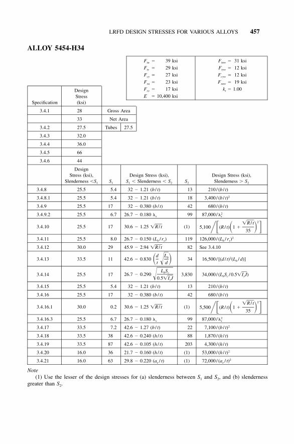
LRFD DESIGN STRESSES FOR VARIOUS ALLOYS 457
ALLOY 5454-H34
F � 39 ksitu
F � 29 ksity
F � 27 ksicy
F � 23 ksisu
F � 17 ksisy
E � 10,400 ksi
F � 31 ksituw
F � 12 ksityw
F � 12 ksicyw
F � 19 ksisuw
k � 1.00t
Specification
DesignStress(ksi)
3.4.1 28 Gross Area
33 Net Area
3.4.2 27.5 Tubes 27.5
3.4.3 32.0
3.4.4 36.0
3.4.5 66
3.4.6 44
DesignStress (ksi),
Slenderness �S1 S1
Design Stress (ksi),S1 � Slenderness � S2 S2
Design Stress (ksi),Slenderness � S2
3.4.8 25.5 5.4 32 � 1.21 (b / t) 13 210 / (b / t)
3.4.8.1 25.5 5.4 32 � 1.21 (b / t) 18 3,400 / (b / t)2
3.4.9 25.5 17 32 � 0.380 (b / t) 42 680 / (b / t)
3.4.9.2 25.5 6.7 26.7 � 0.180 �s 99 87,000 / 2�s
3.4.10 25.5 17 30.6 � 1.25 �R / t (1)2�R / t
5,100 (R / t) 1 �� � � �35
3.4.11 25.5 8.0 26.7 � 0.150 (Lb / ry) 119 126,000 / (Lb / ry)2
3.4.12 30.0 29 45.9 � 2.94 �R / t 82 See 3.4.10
3.4.13 33.5 11 42.6 � 0.830d Lb� ��t d
34 16,500 / [(d / t)2(Lb / d)]
3.4.14 25.5 17 26.7 � 0.290L Sb c�0.5�I Jy
3,830 34,000 / (LbSc / 0.5�I J)y
3.4.15 25.5 5.4 32 � 1.21 (b / t) 13 210 / (b / t)
3.4.16 25.5 17 32 � 0.380 (b / t) 42 680 / (b / t)
3.4.16.1 30.0 0.2 30.6 � 1.25 �R / t (1)2�R / t
5,500 (R / t) 1 �� � � �35
3.4.16.3 25.5 6.7 26.7 � 0.180 �s 99 87,000 / 2�s
3.4.17 33.5 7.2 42.6 � 1.27 (b / t) 22 7,100 / (b / t)2
3.4.18 33.5 38 42.6 � 0.240 (h / t) 88 1,870 / (h / t)
3.4.19 33.5 87 42.6 � 0.105 (h / t) 203 4,300 / (h / t)
3.4.20 16.0 36 21.7 � 0.160 (h / t) (1) 53,000 / (h / t)2
3.4.21 16.0 63 29.8 � 0.220 (ae / t) (1) 72,000 / (ae / t)2
Note(1) Use the lesser of the design stresses for (a) slenderness between S1 and S2, and (b) slenderness
greater than S2.

458 LRFD DESIGN STRESSES FOR VARIOUS ALLOYS
ALLOY 5456-H116
F � 46 ksitu
F � 33 ksity
F � 27 ksicy
F � 27 ksisu
F � 19 ksisy
E � 10,400 ksi
F � 42 ksituw
F � 19 ksityw
F � 19 ksicyw
F � 25 ksisuw
k � 1.00t
Specification
DesignStress(ksi)
3.4.1 31 Gross Area
39 Net Area
3.4.2 31.5 Tubes 31.5
3.4.3 36.5
3.4.4 41.0
3.4.5 78
3.4.6 52
DesignStress (ksi),
Slenderness �S1 S1
Design Stress (ksi),S1 � Slenderness � S2 S2
Design Stress (ksi),Slenderness � S2
3.4.8 25.5 5.4 32 � 1.21 (b / t) 13 210 / (b / t)
3.4.8.1 25.5 5.4 32 � 1.21 (b / t) 18 3,400 / (b / t)2
3.4.9 25.5 17 32 � 0.380 (b / t) 42 680 / (b / t)
3.4.9.2 25.5 6.7 26.7 � 0.180 �s 99 87,000 / 2�s
3.4.10 25.5 17 30.6 � 1.25 �R / t (1)2�R / t
5,100 (R / t) 1 �� � � �35
3.4.11 25.5 8.0 26.7 � 0.150 (Lb / ry) 119 126,000 / (Lb / ry)2
3.4.12 30.0 29 45.9 � 2.94 �R / t 82 See 3.4.10
3.4.13 33.5 11 42.6 � 0.830d Lb� ��t d
34 16,500 / [(d / t)2(Lb / d)]
3.4.14 25.5 17 26.7 � 0.290L Sb c�0.5�I Jy
3,830 34,000 / (LbSc / 0.5�I J)y
3.4.15 25.5 5.4 32 � 1.21 (b / t) 13 210 / (b / t)
3.4.16 25.5 17 32 � 0.380 (b / t) 42 680 / (b / t)
3.4.16.1 30.0 0.2 30.6 � 1.25 �R / t (1)2�R / t
5,500 (R / t) 1 �� � � �35
3.4.16.3 25.5 6.7 26.7 � 0.180 �s 99 87,000 / 2�s
3.4.17 33.5 7.2 42.6 � 1.27 (b / t) 22 7,100 / (b / t)2
3.4.18 33.5 38 42.6 � 0.240 (h / t) 88 1,870 / (h / t)
3.4.19 33.5 87 42.6 � 0.105 (h / t) 203 4,300 / (h / t)
3.4.20 18.0 34 24.5 � 0.192 (h / t) (1) 53,000 / (h / t)2
3.4.21 18.0 60 33.7 � 0.260 (ae / t) (1) 72,000 / (ae / t)2
Note(1) Use the lesser of the design stresses for (a) slenderness between S1 and S2, and (b) slenderness
greater than S2.
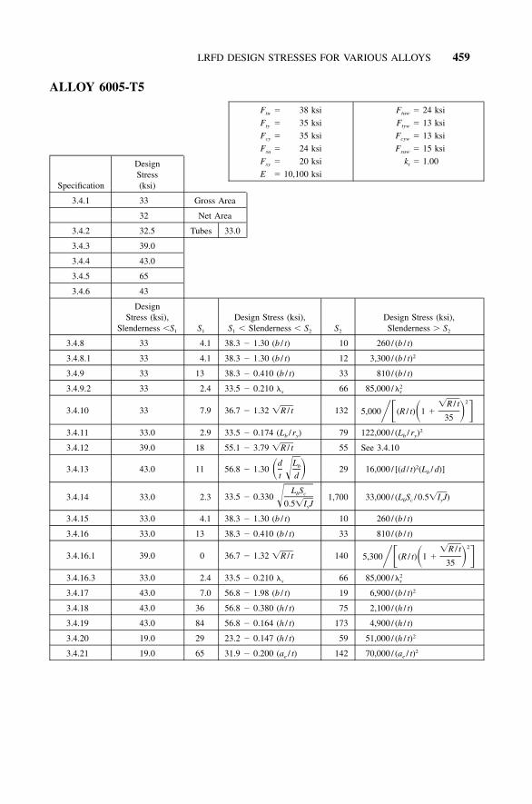
LRFD DESIGN STRESSES FOR VARIOUS ALLOYS 459
ALLOY 6005-T5
F � 38 ksitu
F � 35 ksity
F � 35 ksicy
F � 24 ksisu
F � 20 ksisy
E � 10,100 ksi
F � 24 ksituw
F � 13 ksityw
F � 13 ksicyw
F � 15 ksisuw
k � 1.00t
Specification
DesignStress(ksi)
3.4.1 33 Gross Area
32 Net Area
3.4.2 32.5 Tubes 33.0
3.4.3 39.0
3.4.4 43.0
3.4.5 65
3.4.6 43
DesignStress (ksi),
Slenderness �S1 S1
Design Stress (ksi),S1 � Slenderness � S2 S2
Design Stress (ksi),Slenderness � S2
3.4.8 33 4.1 38.3 � 1.30 (b / t) 10 260 / (b / t)
3.4.8.1 33 4.1 38.3 � 1.30 (b / t) 12 3,300 / (b / t)2
3.4.9 33 13 38.3 � 0.410 (b / t) 33 810 / (b / t)
3.4.9.2 33 2.4 33.5 � 0.210 �s 66 85,000 / 2�s
3.4.10 33 7.9 36.7 � 1.32 �R / t 1322�R / t
5,000 (R / t) 1 �� � � �35
3.4.11 33.0 2.9 33.5 � 0.174 (Lb / ry) 79 122,000 / (Lb / ry)2
3.4.12 39.0 18 55.1 � 3.79 �R / t 55 See 3.4.10
3.4.13 43.0 11 56.8 � 1.30d Lb� ��t d
29 16,000 / [(d / t)2(Lb / d)]
3.4.14 33.0 2.3 33.5 � 0.330L Sb c�0.5�I Jy
1,700 33,000 / (LbSc / 0.5�I J)y
3.4.15 33.0 4.1 38.3 � 1.30 (b / t) 10 260 / (b / t)
3.4.16 33.0 13 38.3 � 0.410 (b / t) 33 810 / (b / t)
3.4.16.1 39.0 0 36.7 � 1.32 �R / t 1402�R / t
5,300 (R / t) 1 �� � � �35
3.4.16.3 33.0 2.4 33.5 � 0.210 �s 66 85,000 / 2�s
3.4.17 43.0 7.0 56.8 � 1.98 (b / t) 19 6,900 / (b / t)2
3.4.18 43.0 36 56.8 � 0.380 (h / t) 75 2,100 / (h / t)
3.4.19 43.0 84 56.8 � 0.164 (h / t) 173 4,900 / (h / t)
3.4.20 19.0 29 23.2 � 0.147 (h / t) 59 51,000 / (h / t)2
3.4.21 19.0 65 31.9 � 0.200 (ae / t) 142 70,000 / (ae / t)2
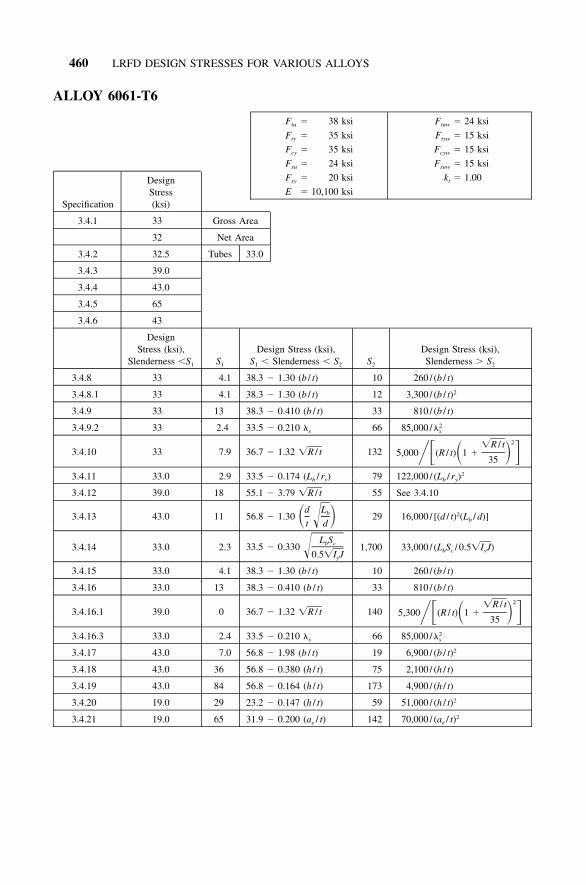
460 LRFD DESIGN STRESSES FOR VARIOUS ALLOYS
ALLOY 6061-T6
F � 38 ksitu
F � 35 ksity
F � 35 ksicy
F � 24 ksisu
F � 20 ksisy
E � 10,100 ksi
F � 24 ksituw
F � 15 ksityw
F � 15 ksicyw
F � 15 ksisuw
k � 1.00t
Specification
DesignStress(ksi)
3.4.1 33 Gross Area
32 Net Area
3.4.2 32.5 Tubes 33.0
3.4.3 39.0
3.4.4 43.0
3.4.5 65
3.4.6 43
DesignStress (ksi),
Slenderness �S1 S1
Design Stress (ksi),S1 � Slenderness � S2 S2
Design Stress (ksi),Slenderness � S2
3.4.8 33 4.1 38.3 � 1.30 (b / t) 10 260 / (b / t)
3.4.8.1 33 4.1 38.3 � 1.30 (b / t) 12 3,300 / (b / t)2
3.4.9 33 13 38.3 � 0.410 (b / t) 33 810 / (b / t)
3.4.9.2 33 2.4 33.5 � 0.210 �s 66 85,000 / 2�s
3.4.10 33 7.9 36.7 � 1.32 �R / t 1322�R / t
5,000 (R / t) 1 �� � � �35
3.4.11 33.0 2.9 33.5 � 0.174 (Lb / ry) 79 122,000 / (Lb / ry)2
3.4.12 39.0 18 55.1 � 3.79 �R / t 55 See 3.4.10
3.4.13 43.0 11 56.8 � 1.30d Lb� ��t d
29 16,000 / [(d / t)2(Lb / d)]
3.4.14 33.0 2.3 33.5 � 0.330L Sb c�0.5�I Jy
1,700 33,000 / (LbSc / 0.5�I J)y
3.4.15 33.0 4.1 38.3 � 1.30 (b / t) 10 260 / (b / t)
3.4.16 33.0 13 38.3 � 0.410 (b / t) 33 810 / (b / t)
3.4.16.1 39.0 0 36.7 � 1.32 �R / t 1402�R / t
5,300 (R / t) 1 �� � � �35
3.4.16.3 33.0 2.4 33.5 � 0.210 �s 66 85,000 / 2�s
3.4.17 43.0 7.0 56.8 � 1.98 (b / t) 19 6,900 / (b / t)2
3.4.18 43.0 36 56.8 � 0.380 (h / t) 75 2,100 / (h / t)
3.4.19 43.0 84 56.8 � 0.164 (h / t) 173 4,900 / (h / t)
3.4.20 19.0 29 23.2 � 0.147 (h / t) 59 51,000 / (h / t)2
3.4.21 19.0 65 31.9 � 0.200 (ae / t) 142 70,000 / (ae / t)2

LRFD DESIGN STRESSES FOR VARIOUS ALLOYS 461
ALLOY 6063-T5
F � 22 ksitu
F � 16 ksity
F � 16 ksicy
F � 13 ksisu
F � 9 ksisy
E � 10,100 ksi
F � 17 ksituw
F � 8 ksityw
F � 8 ksicyw
F � 11 ksisuw
k � 1.00t
Specification
DesignStress(ksi)
3.4.1 15 Gross Area
19 Net Area
3.4.2 15.0 Tubes 15.0
3.4.3 18.0
3.4.4 20.0
3.4.5 37
3.4.6 25
DesignStress (ksi),
Slenderness �S1 S1
Design Stress (ksi),S1 � Slenderness � S2 S2
Design Stress (ksi),Slenderness � S2
3.4.8 15 4.3 16.6 � 0.370 (b / t) 16 168 / (b / t)
3.4.8.1 15 4.3 16.6 � 0.370 (b / t) 18 3,300 / (b / t)2
3.4.9 15 14 16.6 � 0.117 (b / t) 50 540 / (b / t)
3.4.9.2 15 0 14.7 � 0.061 �s 99 85,000 / 2�s
3.4.10 15 8.3 16.3 � 0.450 �R / t (1)2�R / t
5,000 (R / t) 1 �� � � �35
3.4.11 15.0 0 14.7 � 0.051 (Lb / ry) 119 122,000 / (Lb / ry)2
3.4.12 18.0 25 24.5 � 1.29 �R / t 95 See 3.4.10
3.4.13 20.0 11 24.1 � 0.360d Lb� ��t d
45 16,000 / [(d / t)2(Lb / d)]
3.4.14 15.0 0 14.7 � 0.097L Sb c�0.5�I Jy
3,830 33,000 / (LbSc / 0.5�I J)y
3.4.15 15.0 4.3 16.6 � 0.370 (b / t) 16 168 / (b / t)
3.4.16 15.0 14 16.6 � 0.117 (b / t) 50 540 / (b / t)
3.4.16.1 18.0 0 16.3 � 0.450 �R / t (1)2�R / t
5,300 (R / t) 1 �� � � �35
3.4.16.3 15.0 0 14.7 � 0.061 �s 99 85,000 / 2�s
3.4.17 20.0 7.5 24.1 � 0.550 (b / t) 29 6,900 / (b / t)2
3.4.18 20.0 39 24.1 � 0.104 (h / t) 115 1,380 / (h / t)
3.4.19 20.0 91 24.1 � 0.045 (h / t) 270 3,200 / (h / t)
3.4.20 8.5 34 9.9 � 0.041 (h / t) (1) 51,000 / (h / t)2
3.4.21 8.5 91 13.6 � 0.056 (ae / t) (1) 70,000 / (ae / t)2
Note(1) Use the lesser of the design stresses for (a) slenderness between S1 and S2, and (b) slenderness
greater than S2.

462 LRFD DESIGN STRESSES FOR VARIOUS ALLOYS
ALLOY 6063-T6
F � 30 ksitu
F � 25 ksity
F � 25 ksicy
F � 19 ksisu
F � 14 ksisy
E � 10,100 ksi
F � 17 ksituw
F � 8 ksityw
F � 8 ksicyw
F � 11 ksisuw
k � 1.00t
Specification
DesignStress(ksi)
3.4.1 24 Gross Area
26 Net Area
3.4.2 24.0 Tubes 24.0
3.4.3 28.0
3.4.4 31.0
3.4.5 51
3.4.6 34
DesignStress (ksi),
Slenderness �S1 S1
Design Stress (ksi),S1 � Slenderness � S2 S2
Design Stress (ksi),Slenderness � S2
3.4.8 24 3.6 26.7 � 0.760 (b / t) 12 210 / (b / t)
3.4.8.1 24 3.6 26.7 � 0.760 (b / t) 15 3,300 / (b / t)2
3.4.9 24 11 26.7 � 0.240 (b / t) 39 680 / (b / t)
3.4.9.2 24 0 23.5 � 0.123 �s 78 85,000 / 2�s
3.4.10 24 5.2 25.9 � 0.830 �R / t (1)2�R / t
5,000 (R / t) 1 �� � � �35
3.4.11 24.0 0 23.5 � 0.102 (Lb / ry) 94 122,000 / (Lb / ry)2
3.4.12 28.0 21 38.8 � 2.38 �R / t 70 See 3.4.10
3.4.13 31.0 11 39.2 � 0.750d Lb� ��t d
35 16,000 / [(d / t)2(Lb / d)]
3.4.14 24.0 0 23.5 � 0.196L Sb c�0.5�I Jy
2,380 33,000 / (LbSc / 0.5�I J)y
3.4.15 24.0 3.6 26.7 � 0.760 (b / t) 12 210 / (b / t)
3.4.16 24.0 11 26.7 � 0.240 (b / t) 39 680 / (b / t)
3.4.16.1 28.0 0 25.9 � 0.830 �R / t (1)2�R / t
5,300 (R / t) 1 �� � � �35
3.4.16.3 24.0 0 23.5 � 0.123 �s 78 85,000 / 2�s
3.4.17 31.0 7.3 39.2 � 1.13 (b / t) 23 6,900 / (b / t)2
3.4.18 31.0 37 39.2 � 0.220 (h / t) 90 1,770 / (h / t)
3.4.19 31.0 87 39.2 � 0.094 (h / t) 208 4,100 / (h / t)
3.4.20 13.5 28 15.8 � 0.083 (h / t) (1) 51,000 / (h / t)2
3.4.21 13.5 72 21.7 � 0.114 (ae / t) (1) 70,000 / (ae / t)2
Note(1) Use the lesser of the design stresses for (a) slenderness between S1 and S2, and (b) slenderness
greater than S2.
463
APPENDIX JOther Aluminum StructuralDesign Specifications
The Aluminum Association’s Specification for Aluminum Structures isn’t theonly design standard for aluminum, although it does form the basis for manyof the others. These other standards can be divided into two categories: gen-eral standards (like the Specification for Aluminum Structures, hereafter calledthe Aluminum Specification), and application-specific standards, which pro-vide design rules for particular aluminum structural applications, such as pres-sure vessels. The important thing to remember is that all the U.S. specifica-tions are based on the Aluminum Specification, which means they’re the sameas some part of some edition of the Aluminum Specification, or at least theirauthors thought so.
J.1 GENERAL DESIGN SPECIFICATIONS
J.1.1 International Standards
While the Aluminum Specification is the only general design specificationused in the U.S., other nations have their own. The following list isn’t all-inclusive, but it covers much of the English-speaking world:
Australia: The standards-writing body Australia Standards has producedAS 1664, Aluminium Structures, which is based on the Aluminum Specifi-cation with the exception of Section 8, Testing.
Canada: CSA CAN3-S157-M83, Strength Design in Aluminum (96), is anLRFD specification different from the LRFD Aluminum Specification. Pub-lished in 1983 by the Canadian Standards Association (CSA), an update hasbeen drafted but not yet issued.
United Kingdom: British Standard BS 8118, Structural Use of Aluminum,Part I, Code of Practice for Design is also a limit state design specification.
Europe: Eurocode 9, Design of Aluminium Structures CEN/TC250/SC9(102) is a limit state specification issued in 1997 as a prestandard by CEN,the European Committee for Standardization. (The CEN acronym is based onthe French name for this committee, which is Comite Europeen de Normal-isation.) CEN members are the national standards bodies of Austria, Belgium,
464 OTHER ALUMINUM STRUCTURAL DESIGN SPECIFICATIONS
the Czech Republic, Denmark, Finland, France, Germany, Greece, Iceland,Ireland, Italy, Luxembourg, the Netherlands, Norway, Portugal, Spain, Swe-den, Switzerland, and the United Kingdom. Eurocode 9 will be consideredfor adoption as a standard, but in the meantime, these nations may maintaintheir individual national standards.
Eurocode 9 includes:
Part 1.1 Members (including connections)Part 1.2 Structural Fire DesignPart 2 Fatigue
Part 1.2 (Structural Fire Design) is the only code that addresses this issue.International Organization for Standardization: ISO/TR 11069 Alu-
minium Structures—Material and Design—Ultimate Limit State under StaticLoading (116) includes limit state design rules and a commentary. This doc-ument is a technical report rather than an international standard and wasprepared by the ISO technical committee TC167, Steel and Aluminium Struc-tures subcommittee SC 3, Aluminium Structures.
J.1.2 U.S. Building Codes
Three model building code organizations operate in the U.S. Of these, onlythe International Conference of Building Officials (ICBO) based in Whittier,CA, printed its own aluminum design specification as part of its model code,the Uniform Building Code (UBC) (115). (The ‘‘International’’ part of ICBOis something of an overstatement since the UBC hasn’t even been adoptedthroughout the U.S.) The ICBO’s aluminum specification was, however, onlya regurgitation of parts of various previous editions of the Aluminum Speci-fication and included no new or (intentionally) contradictory requirements.
Dealing with the U.S. model building codes appeared to be getting muchsimpler when all three codes of these were merged into the International CodeCouncil’s (ICC) International Building Code (IBC) in 2000, which adoptedthe Aluminum Specification by reference in Chapter 20. Then the NationalFire Protection Association (NFPA) felt the need to promote a competingbuilding code (NFPA 5000). As of this writing, NFPA 5000 is available indraft form only; Chapter 41 is intended for aluminum.
J.2 APPLICATION-SPECIFIC STANDARDS
When aluminum is used in structural applications, design rules unique to thatapplication have often been codified by industry associations. Because steelis also used to make these products, aluminum and steel rules are often foundside by side in the standards.
OTHER ALUMINUM STRUCTURAL DESIGN SPECIFICATIONS 465
J.2.1 Piping
Aluminum’s corrosion-resistance and good mechanical properties at low tem-peratures have led to its use in piping. The standard governing this applicationis the American Society of Mechanical Engineers (ASME) standard B31.3Process Piping (84), formerly called Chemical Plant and Petroleum RefineryPiping. Its scope is piping in petroleum refineries, chemical, pharmaceutical,textile, paper, semiconductor, and cryogenic plants and terminals. Allowablestresses for aluminum piping alloys are given to 400�F.
A nonferrous flange standard (ASME B16.31), which addressed three alu-minum alloys and other nonferrous materials, was published in 1971 but with-drawn in 1981 to avoid conflict with a nickel alloy flange standard (B16.5)published that year. ASME has drafted B16.46, Aluminum Alloy Pipe Flanges,but it has not been approved yet. Aluminum flanges are currently covered inAppendix L to B31.3.
J.2.2 Tanks and Pressure Vessels
For liquefied natural gas (LNG) storage tanks, a cryogenic application, alu-minum is addressed in the American Petroleum Institute (API) Standard 620,Design and Construction of Large, Welded, Low-Pressure Storage Tanks (44),Appendix Q, Low-Pressure Storage Tanks for Liquefied Hydrocarbon Gases.Because this appendix includes steel alloys, its scope limits design metaltemperatures to �270�F or above, but aluminum can also be used at lowertemperatures.
For storage tanks with design temperatures up to 400�F, a more generaldesign standard is ASME B96.1 Welded Aluminum-Alloy Storage Tanks (85).Its scope is vertical, cylindrical, flat-bottom tanks storing liquids at pressuresat or below 1 psi. Design rules in B96.1 are consistent with the AluminumSpecification except that some safety factors are higher to account for thevagaries of field welding. B96.1 also accounts for creep effects at elevatedtemperatures. Used appropriately, this standard provides some allowablestresses for general structural applications of aluminum at elevated tempera-tures, which are otherwise hard to find.
Fixed aluminum dome roofs (as discussed in Section 10.2) and aluminuminternal floating roofs are common on steel storage tanks. The design of theseroofs is addressed in API Standard 650, Welded Steel Tanks for Oil Storage(45), Appendix G, Structurally Supported Aluminum Dome Roofs and Ap-pendix H, Internal Floating Roofs, respectively. These applications are limitedto design temperatures of 200�F or less.
Aluminum dome roofs are also used on steel water-storage tanks; structuraldesign of these roofs is addressed in the American Water Works Association(AWWA) standard D100-96, Welded Steel Tanks for Water Storage, Section15, Structurally Supported Aluminum Dome Roofs. A useful provision of thisstandard is a formula for determining an overall buckling external pressure
466 OTHER ALUMINUM STRUCTURAL DESIGN SPECIFICATIONS
for such domes. This formula gives the same results as we did in Section10.2.3 and the example there. AWWA standard D103-87, Factory-CoatedBolted Steel Tanks for Water Storage, Appendix A, also addresses aluminumdome roofs.
J.2.3 Highway Bridges
The American Association of State Highway and Transportation Officials(AASHTO) maintains standard specifications for highway structures. Statesusually don’t adopt these specifications word for word, but use them as mod-els. For allowable stress design, AASHTO offers Guide Specifications forAluminum Highway Bridges (1991) (36), based on the ASD Aluminum Spec-ification provisions with the safety factors for bridges. Additional considera-tions unique to bridges, such as deflection and slenderness limits and mini-mum thicknesses, are provided. Fatigue provisions are in tabular form, ratherthan presented as equations. For redundant load path structures, allowablefatigue stresses are based on the 5th edition of the Aluminum Specifications(22); for nonredundant load path structures, allowable fatigue stresses arereduced by calculating them for a higher number of cycles than are actuallyanticipated.
For load and resistance factor design, AASHTO provides LRFD BridgeDesign Specifications (1994) (35), Section 7, aluminum structures. This stan-dard has lower resistance factors than those appearing in the LRFD versionof the Aluminum Specification because bridges are designed to have greaterreliability than building structures. The fatigue provisions are based on the5th (1986) edition of the Aluminum Specifications, but they are in the formof an equation rather than a table and are slightly different from the currentAluminum Specification. The AASHTO LRFD Specifications also account forthe variable amplitude loads experienced on bridges by providing a floor onallowable fatigue stresses for variable amplitude loads equal to one-half ofthe constant amplitude fatigue thresholds.
J.2.4 Supports for Highway Signs, Luminaires, and Traffic Signals
AASHTO also publishes Standard Specifications for Structural Supports forHighway Signs, Luminaires, and Traffic Signals. (Everyone else calls lumi-naires light poles.) Section 5, Aluminum Design, uses the Aluminum Speci-fication allowable-stress design. A revised version of this standard has beendrafted; it uses allowable stress design and covers static design of aluminumin Section 6 and fatigue design in Section 11. Fatigue details in Section 11address situations beyond those shown in the Aluminum Specification, butthey are rather conservative for aluminum.
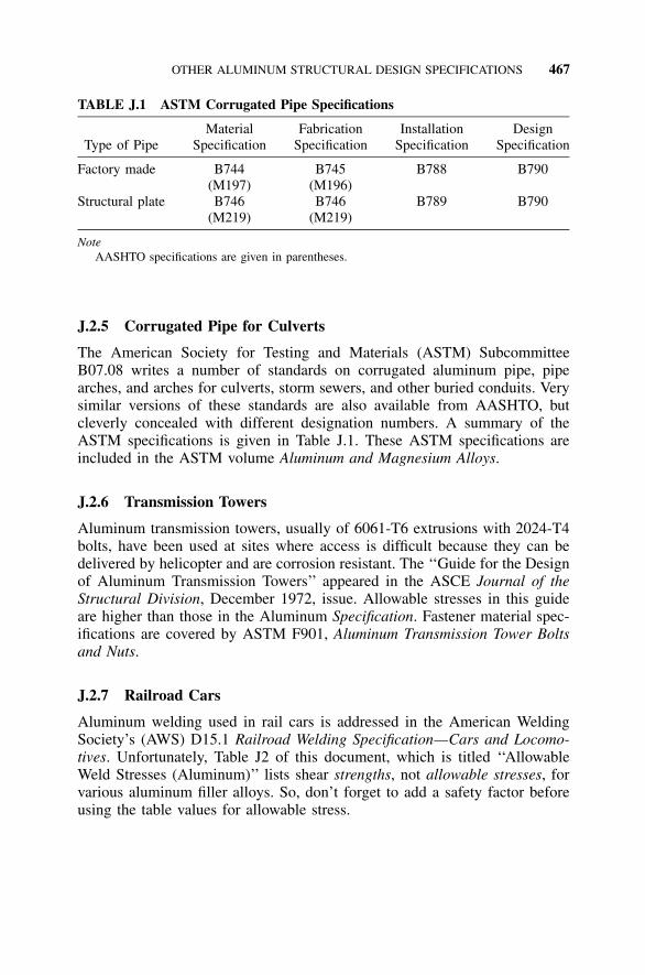
OTHER ALUMINUM STRUCTURAL DESIGN SPECIFICATIONS 467
TABLE J.1 ASTM Corrugated Pipe Specifications
Type of PipeMaterial
SpecificationFabrication
SpecificationInstallation
SpecificationDesign
Specification
Factory made B744 B745 B788 B790(M197) (M196)
Structural plate B746 B746 B789 B790(M219) (M219)
NoteAASHTO specifications are given in parentheses.
J.2.5 Corrugated Pipe for Culverts
The American Society for Testing and Materials (ASTM) SubcommitteeB07.08 writes a number of standards on corrugated aluminum pipe, pipearches, and arches for culverts, storm sewers, and other buried conduits. Verysimilar versions of these standards are also available from AASHTO, butcleverly concealed with different designation numbers. A summary of theASTM specifications is given in Table J.1. These ASTM specifications areincluded in the ASTM volume Aluminum and Magnesium Alloys.
J.2.6 Transmission Towers
Aluminum transmission towers, usually of 6061-T6 extrusions with 2024-T4bolts, have been used at sites where access is difficult because they can bedelivered by helicopter and are corrosion resistant. The ‘‘Guide for the Designof Aluminum Transmission Towers’’ appeared in the ASCE Journal of theStructural Division, December 1972, issue. Allowable stresses in this guideare higher than those in the Aluminum Specification. Fastener material spec-ifications are covered by ASTM F901, Aluminum Transmission Tower Boltsand Nuts.
J.2.7 Railroad Cars
Aluminum welding used in rail cars is addressed in the American WeldingSociety’s (AWS) D15.1 Railroad Welding Specification—Cars and Locomo-tives. Unfortunately, Table J2 of this document, which is titled ‘‘AllowableWeld Stresses (Aluminum)’’ lists shear strengths, not allowable stresses, forvarious aluminum filler alloys. So, don’t forget to add a safety factor beforeusing the table values for allowable stress.

469
APPENDIX KBuckling Constants
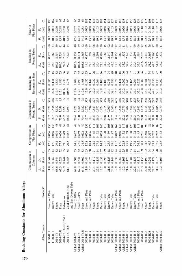
470
Buc
klin
gC
onst
ants
for
Alu
min
umA
lloys
Com
pres
sion
inC
olum
nsC
ompr
essi
onin
Flat
Plat
esC
ompr
essi
onin
Rou
ndT
ubes
Ben
ding
inR
ecta
ngul
arB
ars
Ben
ding
inR
ound
Tub
esSh
ear
inFl
atPl
ates
Allo
yTe
mpe
rPr
oduc
t*B
c
(ksi
)D
c
(ksi
)C
c
Bp
(ksi
)D
p
(ksi
)C
p
Bt
(ksi
)D
t
(ksi
)C
t
Bb
r
(ksi
)D
br
(ksi
)C
br
Btb
(ksi
)D
tb
(ksi
)C
tb
Bs
(ksi
)D
s
(ksi
)C
s
1100
-H12
Shee
tan
dPl
ate
11.0
0.04
416
512
.80.
056
153
12.7
0.37
257
317
.00.
085
133
19.1
0.87
516
08.
20.
029
190
1100
-H14
Dra
wn
Tub
e14
.50.
067
144
17.0
0.08
613
316
.70.
536
446
22.6
0.13
111
525
.11.
260
133
10.7
0.04
316
720
14-T
6Sh
eet
68.6
0.54
452
79.1
0.67
448
74.3
3.13
294
119.
41.
530
5210
9.5
8.75
439
45.1
0.29
064
2014
-T65
1Pl
ate
67.3
0.52
952
77.7
0.65
649
73.0
3.05
995
117.
11.
486
5310
9.5
8.75
441
45.9
0.29
863
2014
-T6,
T65
10,T
6511
Ext
rusi
ons
59.9
0.44
455
69.0
0.54
952
65.2
2.62
910
510
3.6
1.23
856
97.8
7.52
344
40.9
0.25
067
2014
-T6,
T65
1C
old-
Fini
shed
Rod
61.1
0.45
855
70.5
0.56
751
66.5
2.69
910
310
5.9
1.27
855
99.7
7.72
444
42.6
0.26
666
and
Bar
,D
raw
nT
ube
Alc
lad
2014
-T6
Shee
t(0
.039
)64
.80.
502
5374
.80.
622
4970
.42.
922
9811
2.6
1.40
853
103.
68.
157
4042
.60.
267
65A
lcla
d20
14-T
6Sh
eet
(0.2
49)
67.3
0.53
152
77.7
0.65
948
73.0
3.06
894
117.
11.
493
5210
7.6
8.57
139
44.2
0.28
364
Alc
lad
2014
-T65
1Pl
ate
64.8
0.50
253
74.8
0.62
249
70.4
2.92
298
112.
61.
408
5310
5.6
8.36
342
44.2
0.28
364
3003
-H12
Shee
tan
dPl
ate
11.0
0.04
416
512
.80.
056
153
12.7
0.37
257
317
.00.
085
133
19.1
0.87
516
09.
10.
033
182
3003
-H14
Shee
tan
dPl
ate
15.7
0.07
513
818
.40.
096
127
18.1
0.59
441
624
.50.
147
111
27.1
1.39
712
713
.20.
058
151
3003
-H16
Shee
t20
.40.
112
121
24.2
0.14
511
123
.50.
843
327
32.2
0.22
296
35.3
1.98
410
616
.60.
083
134
3003
-H18
Shee
t22
.80.
133
114
27.1
0.17
210
526
.30.
977
295
36.1
0.26
491
39.4
2.29
899
19.2
0.10
312
530
03-H
12D
raw
nT
ube
12.2
0.05
215
714
.20.
065
145
14.1
0.42
452
318
.80.
100
126
21.1
0.99
915
09.
10.
033
182
3003
-H14
Dra
wn
Tub
e18
.00.
093
129
21.3
0.12
011
920
.80.
715
366
28.3
0.18
310
331
.21.
683
115
13.2
0.05
815
130
03-H
16D
raw
nT
ube
21.6
0.12
311
825
.70.
159
108
24.9
0.90
931
034
.10.
243
9437
.42.
140
102
16.6
0.08
313
430
03-H
18D
raw
nT
ube
24.0
0.14
411
228
.60.
187
102
27.7
1.04
628
238
.10.
286
8941
.52.
461
9619
.20.
103
125
Alc
lad
3003
-H12
Shee
tan
dPl
ate
9.9
0.03
817
411
.50.
047
162
11.4
0.32
163
515
.20.
072
140
17.1
0.75
617
28.
20.
029
190
Alc
lad
3003
-H14
Shee
tan
dPl
ate
14.5
0.06
714
417
.00.
086
133
16.7
0.53
644
622
.60.
131
115
25.1
1.26
013
312
.40.
053
156
Alc
lad
3003
-H16
Shee
t19
.20.
103
125
22.8
0.13
211
522
.20.
779
345
30.2
0.20
210
033
.21.
832
111
15.8
0.07
613
8A
lcla
d30
03-H
18Sh
eet
21.6
0.12
311
825
.70.
159
108
24.9
0.90
931
034
.10.
243
9437
.42.
140
102
18.4
0.09
612
8A
lcla
d30
03-H
14D
raw
nT
ube
16.8
0.08
413
319
.90.
108
123
19.4
0.65
438
926
.40.
165
107
29.2
1.53
812
112
.40.
053
156
Alc
lad
3003
-H18
Dra
wn
Tub
e22
.80.
133
114
27.1
0.17
210
526
.30.
977
295
36.1
0.26
491
39.4
2.29
899
18.4
0.09
612
830
04-H
32Sh
eet
and
Plat
e20
.40.
112
121
24.2
0.14
511
123
.50.
843
327
32.2
0.22
296
35.3
1.98
410
616
.60.
083
134
3004
-H34
Shee
tan
dPl
ate
25.3
0.15
510
930
.10.
201
100
29.0
1.11
626
940
.00.
309
8643
.62.
626
9220
.10.
110
122
3004
-H36
Shee
t29
.00.
190
102
34.6
0.24
893
33.2
1.33
423
846
.10.
381
8149
.83.
140
8522
.80.
132
115
3004
-H38
Shee
t33
.90.
241
9440
.70.
317
8638
.81.
643
206
54.2
0.48
774
58.2
3.86
576
25.4
0.15
610
830
04-H
34D
raw
nT
ube
27.7
0.17
810
433
.10.
232
9531
.81.
260
247
44.1
0.35
682
47.7
2.96
687
20.1
0.11
012
230
04-H
36D
raw
nT
ube
31.4
0.21
598
37.7
0.28
289
36.0
1.48
622
050
.10.
433
7754
.03.
497
8022
.80.
132
115
Alc
lad
3004
-H32
Shee
t19
.20.
103
125
22.8
0.13
211
522
.20.
779
345
30.2
0.20
210
033
.21.
832
111
15.8
0.07
613
8
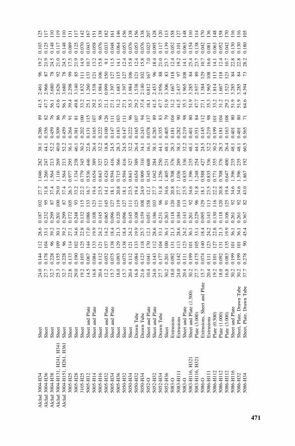
471
Alc
lad
3004
-H34
Shee
t24
.00.
144
112
28.6
0.18
710
227
.71.
046
282
38.1
0.28
689
41.5
2.46
196
19.2
0.10
312
5A
lcla
d30
04-H
36Sh
eet
27.7
0.17
810
433
.10.
232
9531
.81.
260
247
44.1
0.35
682
47.7
2.96
687
21.9
0.12
511
7A
lcla
d30
04-H
38Sh
eet
32.7
0.22
896
39.2
0.29
987
37.4
1.56
421
352
.20.
459
7656
.13.
680
7824
.50.
148
110
Alc
lad
3004
-H13
1,H
241,
H34
1Sh
eet
25.3
0.15
510
930
.10.
201
100
29.0
1.11
626
940
.00.
309
8643
.62.
626
9221
.00.
117
119
Alc
lad
3004
-H15
1,H
261,
H36
1Sh
eet
32.7
0.22
896
39.2
0.29
987
37.4
1.56
421
352
.20.
459
7656
.13.
680
7824
.50.
148
110
3005
-H25
Shee
t22
.80.
133
114
27.1
0.17
210
526
.30.
977
295
36.1
0.26
491
39.4
2.29
899
17.5
0.08
913
130
05-H
28Sh
eet
29.0
0.19
010
234
.60.
248
9333
.21.
334
238
46.1
0.38
181
49.8
3.14
085
21.9
0.12
511
731
05-H
25Sh
eet
19.2
0.10
312
522
.80.
132
115
22.2
0.77
934
530
.20.
202
100
33.2
1.83
211
114
.90.
070
142
5005
-H12
Shee
tan
dPl
ate
14.5
0.06
714
417
.00.
086
133
16.7
0.53
644
622
.60.
131
115
25.1
1.26
013
310
.70.
043
167
5005
-H14
Shee
tan
dPl
ate
16.8
0.08
413
319
.90.
108
123
19.4
0.65
438
926
.40.
165
107
29.2
1.53
812
113
.20.
058
151
5005
-H16
Shee
t20
.40.
112
121
24.2
0.14
511
123
.50.
843
327
32.2
0.22
296
35.3
1.98
410
615
.80.
076
138
5005
-H32
Shee
tan
dPl
ate
12.2
0.05
215
714
.20.
065
145
14.1
0.42
452
318
.80.
100
126
21.1
0.99
915
09.
10.
033
182
5005
-H34
Shee
tan
dPl
ate
15.7
0.07
513
818
.40.
096
127
18.1
0.59
441
624
.50.
147
111
27.1
1.39
712
711
.50.
048
161
5005
-H36
Shee
t18
.00.
093
129
21.3
0.12
011
920
.80.
715
366
28.3
0.18
310
331
.21.
683
115
14.1
0.06
414
650
50-H
32Sh
eet
15.7
0.07
513
818
.40.
096
127
18.1
0.59
441
624
.50.
147
111
27.1
1.39
712
712
.40.
053
156
5050
-H34
Shee
t20
.40.
112
121
24.2
0.14
511
123
.50.
843
327
32.2
0.22
296
35.3
1.98
410
615
.80.
076
138
5050
-H32
Dra
wn
Tub
e16
.80.
084
133
19.9
0.10
812
319
.40.
654
389
26.4
0.16
510
729
.21.
538
121
12.4
0.05
315
650
50-H
34D
raw
nT
ube
21.6
0.12
311
825
.70.
159
108
24.9
0.90
931
034
.10.
243
9437
.42.
140
102
15.8
0.07
613
850
52-O
Shee
tan
dPl
ate
10.4
0.04
117
012
.10.
051
158
12.1
0.34
560
816
.10.
078
137
18.1
0.81
216
77.
00.
023
207
5052
-H32
Shee
tan
dPl
ate
24.0
0.14
311
228
.60.
186
103
27.7
1.04
228
438
.10.
285
8941
.52.
453
9618
.40.
095
128
5052
-H34
Dra
wn
Tub
e27
.70.
177
104
33.1
0.23
196
31.8
1.25
625
044
.10.
355
8347
.72.
956
8821
.00.
117
120
5052
-H36
Shee
t30
.20.
201
100
36.1
0.26
391
34.6
1.40
523
148
.10.
405
7951
.93.
306
8323
.70.
139
113
5083
-OE
xtru
sion
s18
.00.
092
131
21.3
0.11
812
020
.80.
708
376
28.3
0.18
110
431
.21.
667
118
12.4
0.05
215
850
83-H
111
Ext
rusi
ons
24.0
0.14
211
328
.60.
184
104
27.7
1.03
628
938
.10.
282
9041
.52.
437
9719
.20.
101
127
5083
-OSh
eet
and
Plat
e20
.40.
111
123
24.2
0.14
311
323
.50.
835
336
32.2
0.21
998
35.3
1.96
510
814
.10.
063
148
5083
-H11
6,H
321
Shee
tan
dPl
ate
(1.5
00)
30.2
0.19
910
136
.10.
261
9234
.61.
396
235
48.1
0.40
180
51.9
3.28
584
25.4
0.15
411
050
83-H
116,
H32
1Pl
ate
(3.0
00)
27.7
0.17
510
533
.10.
229
9631
.81.
248
254
44.1
0.35
184
47.7
2.93
789
23.7
0.13
811
450
86-O
Ext
rusi
ons,
Shee
tan
dPl
ate
15.7
0.07
414
018
.40.
095
129
18.1
0.58
842
724
.50.
145
112
27.1
1.38
412
910
.70.
042
170
5086
-H11
1E
xtru
sion
s20
.40.
111
123
24.2
0.14
311
323
.50.
835
336
32.2
0.21
998
35.3
1.96
510
816
.60.
081
136
5086
-H11
2Pl
ate
(0.5
00)
19.2
0.10
112
722
.80.
130
116
22.2
0.77
135
530
.20.
199
101
33.2
1.81
411
314
.10.
063
148
5086
-H11
2Pl
ate
(1.0
00)
18.0
0.09
213
121
.30.
118
120
20.8
0.70
837
628
.30.
181
104
31.2
1.66
711
812
.40.
052
158
5086
-H11
2Pl
ate
(3.0
00)
16.8
0.08
313
519
.90.
106
125
19.4
0.64
740
026
.40.
163
108
29.2
1.52
312
310
.70.
042
170
5086
-H11
6Sh
eet
and
Plat
e30
.20.
199
101
36.1
0.26
192
34.6
1.39
623
548
.10.
401
8051
.93.
285
8422
.80.
130
116
5086
-H32
Shee
t,Pl
ate,
Dra
wn
Tub
e30
.20.
199
101
36.1
0.26
192
34.6
1.39
623
548
.10.
401
8051
.93.
285
8422
.80.
130
116
5086
-H34
Shee
t,Pl
ate,
Dra
wn
Tub
e37
.70.
278
9045
.40.
367
8243
.01.
867
192
60.5
0.56
571
64.6
4.39
473
28.2
0.18
010
5
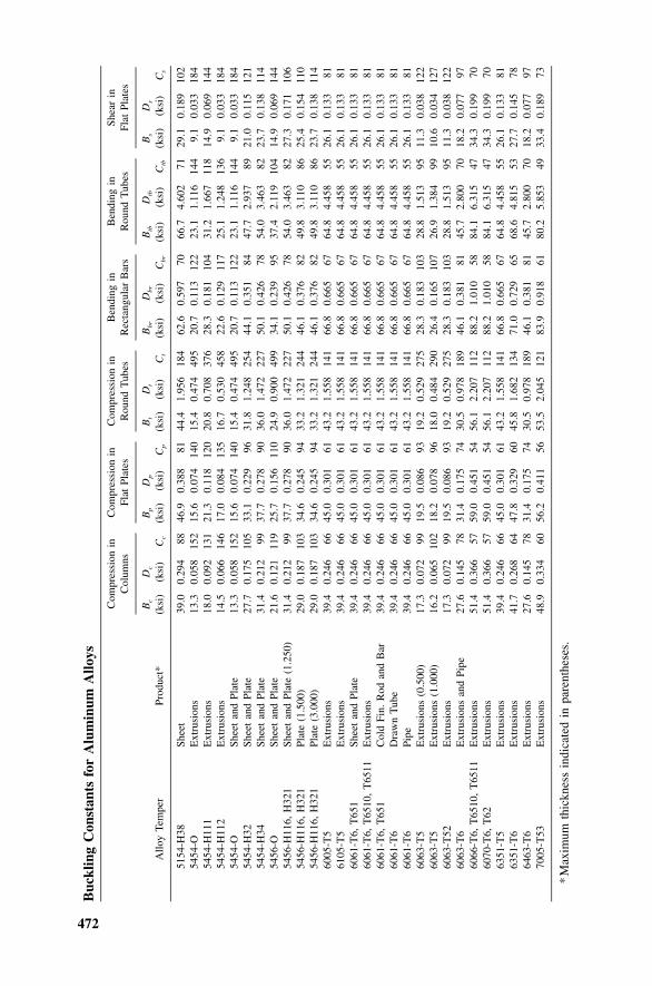
472
Buc
klin
gC
onst
ants
for
Alu
min
umA
lloys
Com
pres
sion
inC
olum
nsC
ompr
essi
onin
Flat
Plat
esC
ompr
essi
onin
Rou
ndT
ubes
Ben
ding
inR
ecta
ngul
arB
ars
Ben
ding
inR
ound
Tub
esSh
ear
inFl
atPl
ates
Allo
yTe
mpe
rPr
oduc
t*B
c
(ksi
)D
c
(ksi
)C
c
Bp
(ksi
)D
p
(ksi
)C
p
Bt
(ksi
)D
t
(ksi
)C
t
Bb
r
(ksi
)D
br
(ksi
)C
br
Btb
(ksi
)D
tb
(ksi
)C
tb
Bs
(ksi
)D
s
(ksi
)C
s
5154
-H38
Shee
t39
.00.
294
8846
.90.
388
8144
.41.
956
184
62.6
0.59
770
66.7
4.60
271
29.1
0.18
910
254
54-O
Ext
rusi
ons
13.3
0.05
815
215
.60.
074
140
15.4
0.47
449
520
.70.
113
122
23.1
1.11
614
49.
10.
033
184
5454
-H11
1E
xtru
sion
s18
.00.
092
131
21.3
0.11
812
020
.80.
708
376
28.3
0.18
110
431
.21.
667
118
14.9
0.06
914
454
54-H
112
Ext
rusi
ons
14.5
0.06
614
617
.00.
084
135
16.7
0.53
045
822
.60.
129
117
25.1
1.24
813
69.
10.
033
184
5454
-OSh
eet
and
Plat
e13
.30.
058
152
15.6
0.07
414
015
.40.
474
495
20.7
0.11
312
223
.11.
116
144
9.1
0.03
318
454
54-H
32Sh
eet
and
Plat
e27
.70.
175
105
33.1
0.22
996
31.8
1.24
825
444
.10.
351
8447
.72.
937
8921
.00.
115
121
5454
-H34
Shee
tan
dPl
ate
31.4
0.21
299
37.7
0.27
890
36.0
1.47
222
750
.10.
426
7854
.03.
463
8223
.70.
138
114
5456
-OSh
eet
and
Plat
e21
.60.
121
119
25.7
0.15
611
024
.90.
900
499
34.1
0.23
995
37.4
2.11
910
414
.90.
069
144
5456
-H11
6,H
321
Shee
tan
dPl
ate
(1.2
50)
31.4
0.21
299
37.7
0.27
890
36.0
1.47
222
750
.10.
426
7854
.03.
463
8227
.30.
171
106
5456
-H11
6,H
321
Plat
e(1
.500
)29
.00.
187
103
34.6
0.24
594
33.2
1.32
124
446
.10.
376
8249
.83.
110
8625
.40.
154
110
5456
-H11
6,H
321
Plat
e(3
.000
)29
.00.
187
103
34.6
0.24
594
33.2
1.32
124
446
.10.
376
8249
.83.
110
8623
.70.
138
114
6005
-T5
Ext
rusi
ons
39.4
0.24
666
45.0
0.30
161
43.2
1.55
814
166
.80.
665
6764
.84.
458
5526
.10.
133
8161
05-T
5E
xtru
sion
s39
.40.
246
6645
.00.
301
6143
.21.
558
141
66.8
0.66
567
64.8
4.45
855
26.1
0.13
381
6061
-T6,
T65
1Sh
eet
and
Plat
e39
.40.
246
6645
.00.
301
6143
.21.
558
141
66.8
0.66
567
64.8
4.45
855
26.1
0.13
381
6061
-T6,
T65
10,
T65
11E
xtru
sion
s39
.40.
246
6645
.00.
301
6143
.21.
558
141
66.8
0.66
567
64.8
4.45
855
26.1
0.13
381
6061
-T6,
T65
1C
old
Fin.
Rod
and
Bar
39.4
0.24
666
45.0
0.30
161
43.2
1.55
814
166
.80.
665
6764
.84.
458
5526
.10.
133
8160
61-T
6D
raw
nT
ube
39.4
0.24
666
45.0
0.30
161
43.2
1.55
814
166
.80.
665
6764
.84.
458
5526
.10.
133
8160
61-T
6Pi
pe39
.40.
246
6645
.00.
301
6143
.21.
558
141
66.8
0.66
567
64.8
4.45
855
26.1
0.13
381
6063
-T5
Ext
rusi
ons
(0.5
00)
17.3
0.07
299
19.5
0.08
693
19.2
0.52
927
528
.30.
183
103
28.8
1.51
395
11.3
0.03
812
260
63-T
5E
xtru
sion
s(1
.000
)16
.20.
065
102
18.2
0.07
896
18.0
0.48
429
026
.40.
165
107
26.9
1.38
499
10.6
0.03
412
760
63-T
52E
xtru
sion
s17
.30.
072
9919
.50.
086
9319
.20.
529
275
28.3
0.18
310
328
.81.
513
9511
.30.
038
122
6063
-T6
Ext
rusi
ons
and
Pipe
27.6
0.14
578
31.4
0.17
574
30.5
0.97
818
946
.10.
381
8145
.72.
800
7018
.20.
077
9760
66-T
6,T
6510
,T
6511
Ext
rusi
ons
51.4
0.36
657
59.0
0.45
154
56.1
2.20
711
288
.21.
010
5884
.16.
315
4734
.30.
199
7060
70-T
6,T
62E
xtru
sion
s51
.40.
366
5759
.00.
451
5456
.12.
207
112
88.2
1.01
058
84.1
6.31
547
34.3
0.19
970
6351
-T5
Ext
rusi
ons
39.4
0.24
666
45.0
0.30
161
43.2
1.55
814
166
.80.
665
6764
.84.
458
5526
.10.
133
8163
51-T
6E
xtru
sion
s41
.70.
268
6447
.80.
329
6045
.81.
682
134
71.0
0.72
965
68.6
4.81
553
27.7
0.14
578
6463
-T6
Ext
rusi
ons
27.6
0.14
578
31.4
0.17
574
30.5
0.97
818
946
.10.
381
8145
.72.
800
7018
.20.
077
9770
05-T
53E
xtru
sion
s48
.90.
334
6056
.20.
411
5653
.52.
045
121
83.9
0.91
861
80.2
5.85
349
33.4
0.18
973
*M
axim
umth
ickn
ess
indi
cate
din
pare
nthe
ses.
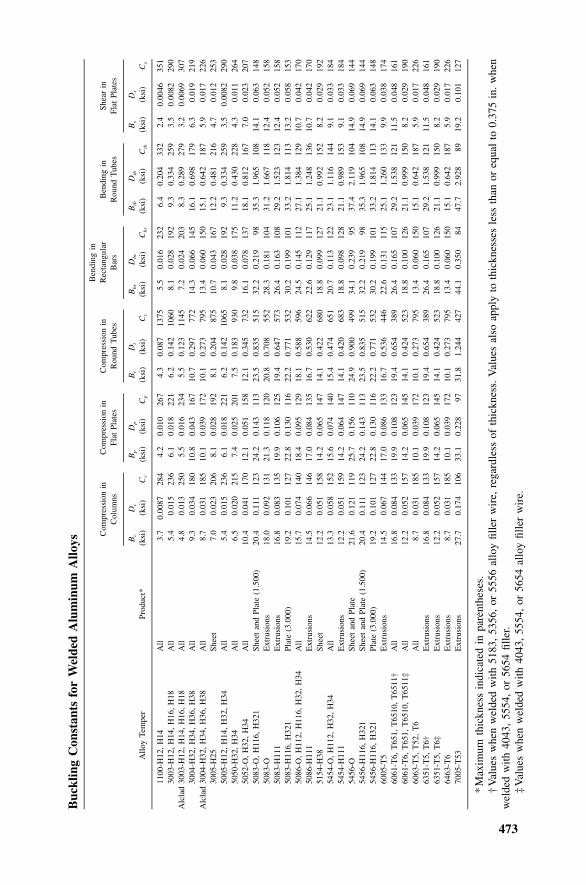
473
Buc
klin
gC
onst
ants
for
Wel
ded
Alu
min
umA
lloys
Com
pres
sion
inC
olum
nsC
ompr
essi
onin
Flat
Plat
esC
ompr
essi
onin
Rou
ndT
ubes
Ben
ding
inR
ecta
ngul
arB
ars
Ben
ding
inR
ound
Tub
esSh
ear
inFl
atPl
ates
Allo
yTe
mpe
rPr
oduc
t*B
c
(ksi
)D
c
(ksi
)C
c
Bp
(ksi
)D
p
(ksi
)C
p
Bt
(ksi
)D
t
(ksi
)C
t
Bb
r
(ksi
)D
br
(ksi
)C
br
Btb
(ksi
)D
tb
(ksi
)C
tb
Bs
(ksi
)D
s
(ksi
)C
s
1100
-H12
,H
14A
ll3.
70.
0087
284
4.2
0.01
026
74.
30.
087
1375
5.5
0.01
623
26.
40.
204
332
2.4
0.00
4635
130
03-H
12,
H14
,H
16,
H18
All
5.4
0.01
523
66.
10.
018
221
6.2
0.14
210
608.
10.
028
192
9.3
0.33
425
93.
50.
0082
290
Alc
lad
3003
-H12
,H
14,
H16
,H
18A
ll4.
80.
013
250
5.5
0.01
623
45.
50.
123
1145
7.2
0.02
420
38.
30.
289
279
3.2
0.00
6930
730
04-H
32,
H34
,H
36,
H38
All
9.3
0.03
418
010
.80.
043
167
10.7
0.29
777
214
.30.
066
145
16.1
0.69
817
96.
30.
019
219
Alc
lad
3004
-H32
,H
34,
H36
,H
38A
ll8.
70.
031
185
10.1
0.03
917
210
.10.
273
795
13.4
0.06
015
015
.10.
642
187
5.9
0.01
722
630
05-H
25Sh
eet
7.0
0.02
320
68.
10.
028
192
8.1
0.20
487
510
.70.
043
167
12.2
0.48
121
64.
70.
012
253
5005
-H12
,H
14,
H32
,H
34A
ll5.
40.
015
236
6.1
0.01
822
16.
20.
142
1065
8.1
0.02
819
29.
30.
334
259
3.5
0.00
8229
050
50-H
32,
H34
All
6.5
0.02
021
57.
40.
025
201
7.5
0.18
393
09.
80.
038
175
11.2
0.43
022
84.
30.
011
264
5052
-O,
H32
,H
34A
ll10
.40.
041
170
12.1
0.05
115
812
.10.
345
732
16.1
0.07
813
718
.10.
812
167
7.0
0.02
320
750
83-O
,H
116,
H32
1Sh
eet
and
Plat
e(1
.500
)20
.40.
111
123
24.2
0.14
311
323
.50.
835
515
32.2
0.21
998
35.3
1.96
510
814
.10.
063
148
5083
-OE
xtru
sion
s18
.00.
092
131
21.3
0.11
812
020
.80.
708
552
28.3
0.18
110
431
.21.
667
118
12.4
0.05
215
850
83-H
111
Ext
rusi
ons
16.8
0.08
313
519
.90.
106
125
19.4
0.64
757
326
.40.
163
108
29.2
1.52
312
312
.40.
052
158
5083
-H11
6,H
321
Plat
e(3
.000
)19
.20.
101
127
22.8
0.13
011
622
.20.
771
532
30.2
0.19
910
133
.21.
814
113
13.2
0.05
815
350
86-O
,H
112,
H11
6,H
32,
H34
All
15.7
0.07
414
018
.40.
095
129
18.1
0.58
859
624
.50.
145
112
27.1
1.38
412
910
.70.
042
170
5086
-H11
1E
xtru
sion
s14
.50.
066
146
17.0
0.08
413
516
.70.
530
622
22.6
0.12
911
725
.11.
248
136
10.7
0.04
217
051
54-H
38Sh
eet
12.2
0.05
115
814
.20.
065
147
14.1
0.42
268
018
.80.
099
127
21.1
0.99
215
28.
20.
029
192
5454
-O,
H11
2,H
32,
H34
All
13.3
0.05
815
215
.60.
074
140
15.4
0.47
465
120
.70.
113
122
23.1
1.11
614
49.
10.
033
184
5454
-H11
1E
xtru
sion
s12
.20.
051
159
14.2
0.06
414
714
.10.
420
683
18.8
0.09
812
821
.10.
989
153
9.1
0.03
318
454
56-O
Shee
tan
dPl
ate
21.6
0.12
111
925
.70.
156
110
24.9
0.90
049
934
.10.
239
9537
.42.
119
104
14.9
0.06
914
454
56-H
116,
H32
1Sh
eet
and
Plat
e(1
.500
)20
.40.
111
123
24.2
0.14
311
323
.50.
835
515
32.2
0.21
998
35.3
1.96
510
814
.90.
069
144
5456
-H11
6,H
321
Plat
e(3
.000
)19
.20.
101
127
22.8
0.13
011
622
.20.
771
532
30.2
0.19
910
133
.21.
814
113
14.1
0.06
314
860
05-T
5E
xtru
sion
s14
.50.
067
144
17.0
0.08
613
316
.70.
536
446
22.6
0.13
111
525
.11.
260
133
9.9
0.03
817
460
61-T
6,T
651,
T65
10,
T65
11†
All
16.8
0.08
413
319
.90.
108
123
19.4
0.65
438
926
.40.
165
107
29.2
1.53
812
111
.50.
048
161
6061
-T6,
T65
1,T
6510
,T
6511
‡A
ll12
.20.
052
157
14.2
0.06
514
514
.10.
424
523
18.8
0.10
012
621
.10.
999
150
8.2
0.02
919
060
63-T
5,T
52,
T6
All
8.7
0.03
118
510
.10.
039
172
10.1
0.27
379
513
.40.
060
150
15.1
0.64
218
75.
90.
017
226
6351
-T5,
T6†
Ext
rusi
ons
16.8
0.08
413
319
.90.
108
123
19.4
0.65
438
926
.40.
165
107
29.2
1.53
812
111
.50.
048
161
6351
-T5,
T6‡
Ext
rusi
ons
12.2
0.05
215
714
.20.
065
145
14.1
0.42
452
318
.80.
100
126
21.1
0.99
915
08.
20.
029
190
6463
-T6
Ext
rusi
ons
8.7
0.03
118
510
.10.
039
172
10.1
0.27
379
513
.40.
060
150
15.1
0.64
218
75.
90.
017
226
7005
-T53
Ext
rusi
ons
27.7
0.17
410
633
.10.
228
9731
.81.
244
427
44.1
0.35
084
47.7
2.92
889
19.2
0.10
112
7
*M
axim
umth
ickn
ess
indi
cate
din
pare
nthe
ses.
†V
alue
sw
hen
wel
ded
with
5183
,53
56,
or55
56al
loy
fille
rw
ire,
rega
rdle
ssof
thic
knes
s.V
alue
sal
soap
ply
toth
ickn
esse
sle
ssth
anor
equa
lto
0.37
5in
.whe
nw
elde
dw
ith40
43,
5554
,or
5654
fille
r.‡
Val
ues
whe
nw
elde
dw
ith40
43,
5554
,or
5654
allo
yfil
ler
wir
e.

475
APPENDIX LMetric Conversions
If you’re like us, your problem with metric conversion charts is that theyprovide too much information. In structural design, you don’t need to knowhow many becquerels are in a curie; you’re just trying to remember if anewton is a measure of force or some kind of junk food. The conversionsgiven here are what you need—but first a few comments.
No topic—other than LRFD, perhaps—elicits so many opinions from en-gineers besides metrication. That’s probably because most people figure thatyou don’t have to know much to comment on the topic. That might be worthrethinking. Before questioning conversions, let’s review. There are two typesof conversions from the foot-pound system (commonly referred to as the‘‘U.S. customary units’’; ironic considering that it’s from England) to SI (theInternational System of Units, known by its French acronym and commonlycalled the metric system):
Soft conversion is conversion of foot-pound units to metric units withoutmodifying the result to an even, convenient round number in metric units.For example, converting 1 in. to 25.4 mm is a soft conversion.
Hard conversion is conversion of foot-pound units to metric units andmodifying the result to an even, convenient round number in metric units.Converting 1 in. to 25 mm is a hard conversion.
Most U.S. standards, such as ASTM material specifications, use hard con-versions. For example, ASTM B221M lists the tensile ultimate strength of6061 extrusion as 260 MPa, even though ASTM B221 shows it as 38 ksi,which is actually 262.0024 . . . MPa. Just as most aluminum strengths arerounded to the nearest 1 ksi in the foot-pound system, most strengths arerounded to the nearest 5 MPa in the SI system. In this book, where quantitiesare taken from standards, we’ve used the SI version of the standard for theSI quantity. The round-off usually is less than the accuracy in the foot-poundquantity; if you think it’s worth worrying about, consider how accurate moststructural design is. We have not given SI dimensions for fastener and pipesizes because the schedules of available sizes for these are completely dif-ferent from the U.S. schedules and, frankly, we don’t often deal with them.
For simplicity’s sake, you might want to try this in your calculations: con-vert in. to mm, lb to N, and ksi to MPa. That should take care of 80% of theconversions in common structural design. This approach works well becausethe resulting SI quantities are generally convenient numbers (not too large,
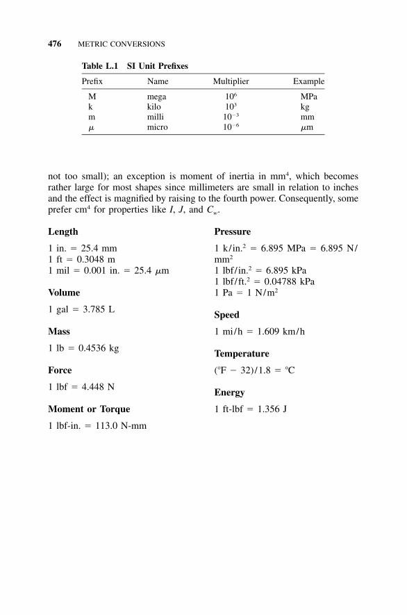
476 METRIC CONVERSIONS
Table L.1 SI Unit Prefixes
Prefix Name Multiplier Example
M mega 106 MPak kilo 103 kgm milli 10�3 mm� micro 10�6 �m
not too small); an exception is moment of inertia in mm4, which becomesrather large for most shapes since millimeters are small in relation to inchesand the effect is magnified by raising to the fourth power. Consequently, someprefer cm4 for properties like I, J, and Cw.
Length
1 in. � 25.4 mm1 ft � 0.3048 m1 mil � 0.001 in. � 25.4 �m
Volume
1 gal � 3.785 L
Mass
1 lb � 0.4536 kg
Force
1 lbf � 4.448 N
Moment or Torque
1 lbf-in. � 113.0 N-mm
Pressure
1 k/in.2 � 6.895 MPa � 6.895 N/mm2
1 lbf/ in.2 � 6.895 kPa1 lbf/ft.2 � 0.04788 kPa1 Pa � 1 N/m2
Speed
1 mi/h � 1.609 km/h
Temperature
(�F � 32)/1.8 � �C
Energy
1 ft-lbf � 1.356 J
477
APPENDIX MStatistics
We increasingly find ourselves facing statistical expressions that we are ex-pected to decipher. For many of us, however, our recall with respect to sta-tistics is limited to the adage, ‘‘There are liars, damned liars, and statisticians.’’Another adage proclaims, ‘‘If you torture data long enough, it will confess toanything.’’ While it is useful to invoke these sayings as reminders that weshould regard statistical claims with a healthy dose of skepticism, they do nothelp us come to an understanding of the statistical issue at hand.
The statistical questions that we most frequently encounter as engineersdeal in one way or another with the evaluation of test results. We love tocollect data and make some assertions. In order for the validity of our asser-tions to be quantified in some way, however, we are obligated to assign somestatistical measure to our results.
We may use statistics to describe a characteristic of a population by a singlevalue when, in reality, values for this characteristic vary within the population.For example, the actual height of trees within a population varies from treeto tree, but we may wish to characterize the entire population in terms of theaverage height of the individual trees. Similarly, we may wish to characterizeall production of a given aluminum alloy in terms of a specified minimumstrength. Statisticians have developed their own jargon for discussing theseissues, so let’s begin by learning to talk the talk.
TALK THE TALK
Distribution refers to the relationship of individuals within a population tothe average for that population. Some individuals will be above average, andothers will be below average. The characteristic of the population that ismeasured or observed is the variable. We plot the distribution with the x-axisshowing the measured values of our variable, and the y-axis showing theportion of the population that is observed to match a given value. The distri-bution may be described by means of two parameters. The plot of the dis-tribution is located along the x-axis by its mean, and the spread of the dis-tribution may be described by either its variance or its standard deviation.
Mean is the arithmetic average of the values determined for each individualwithin the population for the variable in question. When the distribution is
478 STATISTICS
plotted, the mean determines its location along the x-axis. It is considered aparameter of the distribution.
Normal distribution refers to a class of distribution that meets certain cri-teria, including symmetry of the distribution about the mean. A plot of thenormal distribution resembles the familiar bell curve. It is routinely describedin terms of two parameters, the mean and the standard deviation.
Parameter refers to some measure of the distribution of the variable. Pa-ameters may be estimates of specified points, such as the mean or a minimumexpected value. Parameters may also be used to describe the spread of thedistribution, in terms of its variance or its standard deviation.
Population refers to the entire universe of individuals that may fit ourcategory. For example, when we are evaluating the response of medical pa-tients to a given drug, the population is every patient who may ever take thatdrug. Similarly, when we are determining the growth rate of a given speciesof tree, the population is every tree of that species that may ever exist. Cor-respondingly, when we are determining the strength of a given aluminumalloy, the population includes every ingot of that alloy that might ever beproduced.
Standard deviation is the square root of the variance and is a preferredmeasure of the spread of the distribution in that it is expressed in the sameunits as the variable.
Variable refers to the characteristic of the population that we measure orobserve, such as the height of the tree or the strength of the metal.
Variance is a measure of the spread of the distribution. This refers to theextent to which individual values deviate from the average, or mean, value.The spread is also referred to as the variability of the data.
WALK THE TALK
Let’s use the measured speed of the vehicles passing a highway checkpointto illustrate the concept of distribution. Our hypothetical checkpoint measuredthe speed of 100 vehicles, and recorded the following results:
Speed (miles per hour) Number of Vehicles Portion of the Population
62 4 0.0464 11 0.1166 22 0.2268 26 0.2670 22 0.2272 11 0.1174 4 0.04
100
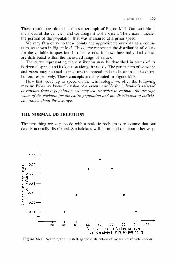
STATISTICS 479
Figure M-1 Scattergraph illustrating the distribution of measured vehicle speeds.
These results are plotted in the scattergraph of Figure M-1. Our variable isthe speed of the vehicles, and we assign it to the x-axis. The y-axis indicatesthe portion of the population that was measured at a given speed.
We may fit a curve to these points and approximate our data as a contin-uum, as shown in Figure M-2. This curve represents the distribution of valuesfor the variable in question. In other words, it shows how individual valuesare distributed within the measured range of values.
The curve representing the distribution may be described in terms of itshorizontal spread and its location along the x-axis. The parameters of varianceand mean may be used to measure the spread and the location of the distri-bution, respectively. These concepts are illustrated in Figure M-3.
Now that we’re up to speed on the terminology, we offer the followingmaxim: When we know the value of a given variable for individuals selectedat random from a population, we may use statistics to estimate the averagevalue of the variable for the entire population and the distribution of individ-ual values about the average.
THE NORMAL DISTRIBUTION
The first thing we want to do with a real-life problem is to assume that ourdata is normally distributed. Statisticians will go on and on about other ways
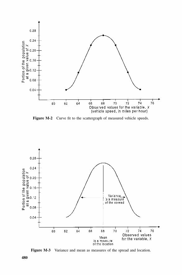
480
Figure M-2 Curve fit to the scattergraph of measured vehicle speeds.
Figure M-3 Variance and mean as measures of the spread and location.
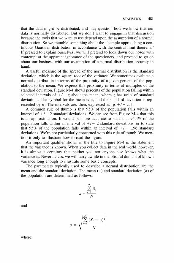
STATISTICS 481
that the data might be distributed, and may question how we know that ourdata is normally distributed. But we don’t want to engage in that discussionbecause the tools that we want to use depend upon the assumption of a normaldistribution. So we mumble something about the ‘‘sample approaching a con-tinuous Gaussian distribution in accordance with the central limit theorem.’’If pressed to explain ourselves, we will pretend to look down our noses withcontempt at the apparent ignorance of the questioners, and proceed to go onabout our business with our assumption of a normal distribution securely inhand.
A useful measure of the spread of the normal distribution is the standarddeviation, which is the square root of the variance. We sometimes evaluate anormal distribution in terms of the proximity of a given percent of the pop-ulation to the mean. We express this proximity in terms of multiples of thestandard deviation. Figure M-4 shows percents of the population falling withinselected intervals of � /� z about the mean, where z has units of standarddeviations. The symbol for the mean is �, and the standard deviation is rep-resented by �. The intervals are, then, expressed as [� � /� z�].
A common rule of thumb is that 95% of the population falls within aninterval of � /� 2 standard deviations. We can see from Figure M-4 that thisis an approximation. It would be more accurate to state that 95.4% of thepopulation falls within an interval of � /� 2 standard deviations, or to statethat 95% of the population falls within an interval of � /� 1.96 standarddeviations. We’re not particularly concerned with this rule of thumb. We men-tion it only to illustrate how to read the figure.
An important qualifier shown in the title to Figure M-4 is the statementthat the variance is known. When you collect data in the real world, however,it is almost a certainty that neither you nor anyone else knows what thevariance is. Nevertheless, we will tarry awhile in the blissful domain of knownvariance long enough to illustrate some basic concepts.
The parameters typically used to describe a normal distribution are themean and the standard deviation. The mean (�) and standard deviation (�) ofthe population are determined as follows:
N
X� ii�1� �
N
and
N2(X � �)� i
i�1� � � N
where:
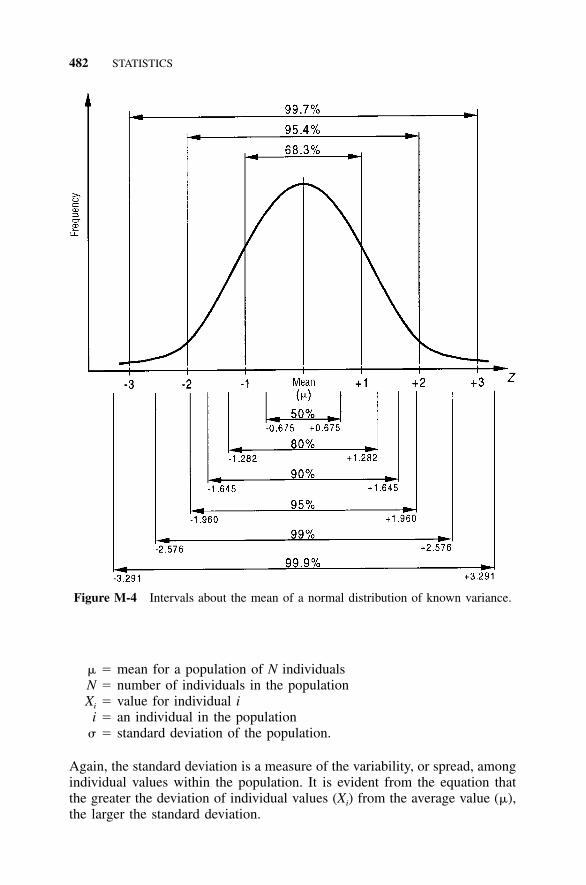
482 STATISTICS
Figure M-4 Intervals about the mean of a normal distribution of known variance.
� � mean for a population of N individualsN � number of individuals in the populationXi � value for individual i
i � an individual in the population� � standard deviation of the population.
Again, the standard deviation is a measure of the variability, or spread, amongindividual values within the population. It is evident from the equation thatthe greater the deviation of individual values (Xi) from the average value (�),the larger the standard deviation.
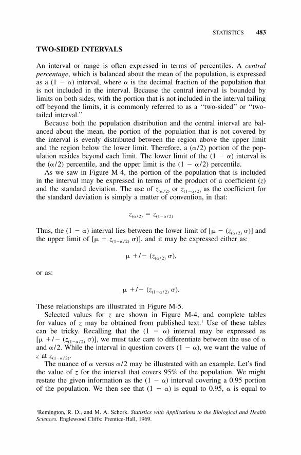
STATISTICS 483
TWO-SIDED INTERVALS
An interval or range is often expressed in terms of percentiles. A centralpercentage, which is balanced about the mean of the population, is expressedas a (1 � �) interval, where � is the decimal fraction of the population thatis not included in the interval. Because the central interval is bounded bylimits on both sides, with the portion that is not included in the interval tailingoff beyond the limits, it is commonly referred to as a ‘‘two-sided’’ or ‘‘two-tailed interval.’’
Because both the population distribution and the central interval are bal-anced about the mean, the portion of the population that is not covered bythe interval is evenly distributed between the region above the upper limitand the region below the lower limit. Therefore, a (� /2) portion of the pop-ulation resides beyond each limit. The lower limit of the (1 � �) interval isthe (� /2) percentile, and the upper limit is the (1 � � /2) percentile.
As we saw in Figure M-4, the portion of the population that is includedin the interval may be expressed in terms of the product of a coefficient (z)and the standard deviation. The use of z(� / 2) or z(1�� / 2) as the coefficient forthe standard deviation is simply a matter of convention, in that:
z � z(� / 2) (1�� / 2)
Thus, the (1 � �) interval lies between the lower limit of [� � (z(� / 2) �)] andthe upper limit of [� � z(1�� / 2) �)], and it may be expressed either as:
� � /� (z �),(� / 2)
or as:
� � /� (z �).(1�� / 2)
These relationships are illustrated in Figure M-5.Selected values for z are shown in Figure M-4, and complete tables
for values of z may be obtained from published text.1 Use of these tablescan be tricky. Recalling that the (1 � �) interval may be expressed as[� � /� (z(1�� / 2) �)], we must take care to differentiate between the use of �and � /2. While the interval in question covers (1 � �), we want the value ofz at z(1�� / 2).
The nuance of � versus � /2 may be illustrated with an example. Let’s findthe value of z for the interval that covers 95% of the population. We mightrestate the given information as the (1 � �) interval covering a 0.95 portionof the population. We then see that (1 � �) is equal to 0.95, � is equal to
1Remington, R. D., and M. A. Schork. Statistics with Applications to the Biological and HealthSciences. Englewood Cliffs: Prentice-Hall, 1969.
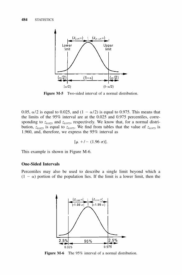
484 STATISTICS
Figure M-5 Two-sided interval of a normal distribution.
Figure M-6 The 95% interval of a normal distribution.
0.05, � /2 is equal to 0.025, and (1 � � /2) is equal to 0.975. This means thatthe limits of the 95% interval are at the 0.025 and 0.975 percentiles, corre-sponding to z0.025 and z0.975, respectively. We know that, for a normal distri-bution, z0.025 is equal to z0.975. We find from tables that the value of z0.975 is1.960, and, therefore, we express the 95% interval as
[� � /� (1.96 �)].
This example is shown in Figure M-6.
One-Sided Intervals
Percentiles may also be used to describe a single limit beyond which a(1 � �) portion of the population lies. If the limit is a lower limit, then the
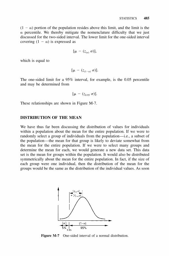
STATISTICS 485
Figure M-7 One-sided interval of a normal distribution.
(1 � �) portion of the population resides above this limit, and the limit is the� percentile. We thereby mitigate the nomenclature difficulty that we justdiscussed for the two-sided interval. The lower limit for the one-sided intervalcovering (1 � �) is expressed as
[� � (z �)],(�)
which is equal to
[� � (z �)].(1��)
The one-sided limit for a 95% interval, for example, is the 0.05 percentileand may be determined from
[� � (z �)].0.95
These relationships are shown in Figure M-7.
DISTRIBUTION OF THE MEAN
We have thus far been discussing the distribution of values for individualswithin a population about the mean for the entire population. If we were torandomly select a group of individuals from the population—i.e., a subset ofthe population—the mean for that group is likely to deviate somewhat fromthe mean for the entire population. If we were to select many groups anddetermine the mean for each, we would generate a new data set. This dataset is the mean for groups within the population. It would also be distributedsymmetrically about the mean for the entire population. In fact, if the size ofeach group were one individual, then the distribution of the mean for thegroups would be the same as the distribution of the individual values. As soon
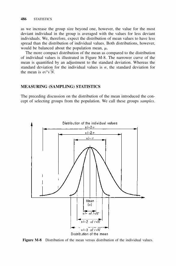
486 STATISTICS
Figure M-8 Distribution of the mean versus distribution of the individual values.
as we increase the group size beyond one, however, the value for the mostdeviant individual in the group is averaged with the values for less deviantindividuals. We, therefore, expect the distribution of mean values to have lessspread than the distribution of individual values. Both distributions, however,would be balanced about the population mean, �.
The more compact distribution of the mean as compared to the distributionof individual values is illustrated in Figure M-8. The narrower curve of themean is quantified by an adjustment to the standard deviation. Whereas thestandard deviation for the individual values is �, the standard deviation forthe mean is � /�N.
MEASURING (SAMPLING) STATISTICS
The preceding discussion on the distribution of the mean introduced the con-cept of selecting groups from the population. We call these groups samples.

STATISTICS 487
In the real world, we never know the true characteristics of the entire theo-retically possible population. We may generate a limited amount of data byperforming tests on a sample of the population. Next, we apply statistics toestimate the characteristics of the entire population from our sample data.This process of attempting to infer the characteristics of a population frommeasurements of a portion (sample) of that population is referred to as sta-tistical inference.
We may think of statistical inference as a systematic method for expressingnot only what we know, but also how well we know it. We estimate valuesfor the parameters in question, and we additionally calculate the level ofconfidence that we have in our estimates.
We will see that this concept of confidence is critical to our application ofstatistics to real-world problems. We felt it best to keep it out of sight, how-ever, until after we had introduced you to the basic concepts of a normaldistribution. Since we have neglected it for this long, let’s ignore it a little bitlonger while we wrap up our presentation of the mean and the standarddeviation.
The best estimates of the true values of the parameters of the populationare the values that we measure from our sample. Thus, we will estimate thatthe population mean (�) is the same as the sample mean and that the(x),population standard deviation (�) is the same as the sample standard deviation(s). Values for and s are obtained from the test data as follows:x
n
x� ii�1x �
n
n2(x � x)� i
i�1s � � n � 1
where:
�x mean for a sample of n individualsn � number of individuals in the samplexi � value for individual ii � an individual in the samples � standard deviation of the sample.
As with the population parameters, the standard deviation of the mean isrelated to the standard deviation of the individual values by a factor of(1/�n).
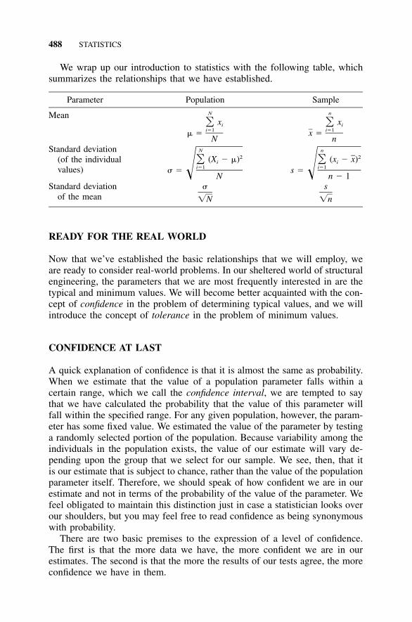
488 STATISTICS
We wrap up our introduction to statistics with the following table, whichsummarizes the relationships that we have established.
Parameter Population Sample
Mean N
x� ii�1� �
N
n
x� ii�1x �
nStandard deviation
(of the individualvalues)
N2(X � �)� i
i�1� � � N
n2(x � x)� i
i�1s � � n � 1Standard deviation
of the mean�
�N
s
�n
READY FOR THE REAL WORLD
Now that we’ve established the basic relationships that we will employ, weare ready to consider real-world problems. In our sheltered world of structuralengineering, the parameters that we are most frequently interested in are thetypical and minimum values. We will become better acquainted with the con-cept of confidence in the problem of determining typical values, and we willintroduce the concept of tolerance in the problem of minimum values.
CONFIDENCE AT LAST
A quick explanation of confidence is that it is almost the same as probability.When we estimate that the value of a population parameter falls within acertain range, which we call the confidence interval, we are tempted to saythat we have calculated the probability that the value of this parameter willfall within the specified range. For any given population, however, the param-eter has some fixed value. We estimated the value of the parameter by testinga randomly selected portion of the population. Because variability among theindividuals in the population exists, the value of our estimate will vary de-pending upon the group that we select for our sample. We see, then, that itis our estimate that is subject to chance, rather than the value of the populationparameter itself. Therefore, we should speak of how confident we are in ourestimate and not in terms of the probability of the value of the parameter. Wefeel obligated to maintain this distinction just in case a statistician looks overour shoulders, but you may feel free to read confidence as being synonymouswith probability.
There are two basic premises to the expression of a level of confidence.The first is that the more data we have, the more confident we are in ourestimates. The second is that the more the results of our tests agree, the moreconfidence we have in them.
STATISTICS 489
DETERMINATION OF TYPICAL VALUES
When we speak of the typical value of a variable, we are referring to theaverage. Our parameter, then, is the mean. The sample mean is our estimateof the population mean, and the confidence interval is a range around thesample mean that we predict will include the population mean.
We discussed earlier that we may describe an interval in terms of multiplesof the standard deviation about the mean. In the hypothetical scenario ofknown variance, we have presented the following expression to describe aninterval about the mean for the distribution of the individual values:
� � /� z �(1�� / 2)
For the discussion of the mean, we adjust the standard deviation by thefactor, and an interval about the mean may be written as follows:(1/�N)
�� � /� z(1�� / 2) �N
We replace the population parameters �, �, and N with the sample parameterss, and n, respectively, to apply this expression to our sample data. Wex,
recall, however, that in our real-world problem the variance is not known, andthe sample mean and sample standard deviation (s) are only estimates of(x)the population mean (�) and population standard deviation (�). The coeffi-cient z must, therefore, be replaced with a multiplier that incorporates theadditional uncertainty accruing from the unknown variance.
A very clever person who worked for a beer company figured out whatthe distribution for this modified coefficient should be. He wrote his findingsunder the pseudonym ‘‘Student’’ and, although it is now known that his namewas W. S. Gossett and he worked for the Guinness brewery, we still refer tothis distribution by the quirky moniker ‘‘Student’s t.’’ We will, then, replacez with the Student’s t-distribution (or just t-distribution, for brevity). Theconfidence interval for the sample mean may then be written as follows:
sx � /� t(1�� / 2) �n
TROUBLES WITH THE t-DISTRIBUTION
We would be ready now to express the confidence interval for our estimateof the mean, or typical, value if only we could read the t-distribution chart.Both the rows and the columns can be tricky to navigate.
The difficulty with the columns is that they are often labeled in terms ofthe percentile. As we mentioned when we introduced the concept of intervals,
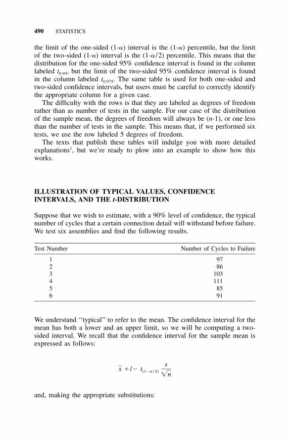
490 STATISTICS
the limit of the one-sided (1-�) interval is the (1-�) percentile, but the limitof the two-sided (1-�) interval is the (1-� /2) percentile. This means that thedistribution for the one-sided 95% confidence interval is found in the columnlabeled t0.95, but the limit of the two-sided 95% confidence interval is foundin the column labeled t0.975. The same table is used for both one-sided andtwo-sided confidence intervals, but users must be careful to correctly identifythe appropriate column for a given case.
The difficulty with the rows is that they are labeled as degrees of freedomrather than as number of tests in the sample. For our case of the distributionof the sample mean, the degrees of freedom will always be (n-1), or one lessthan the number of tests in the sample. This means that, if we performed sixtests, we use the row labeled 5 degrees of freedom.
The texts that publish these tables will indulge you with more detailedexplanations1, but we’re ready to plow into an example to show how thisworks.
ILLUSTRATION OF TYPICAL VALUES, CONFIDENCEINTERVALS, AND THE t-DISTRIBUTION
Suppose that we wish to estimate, with a 90% level of confidence, the typicalnumber of cycles that a certain connection detail will withstand before failure.We test six assemblies and find the following results.
Test Number Number of Cycles to Failure
1 972 863 1034 1115 856 91
We understand ‘‘typical’’ to refer to the mean. The confidence interval for themean has both a lower and an upper limit, so we will be computing a two-sided interval. We recall that the confidence interval for the sample mean isexpressed as follows:
sx � /� t(1�� / 2) �n
and, making the appropriate substitutions:
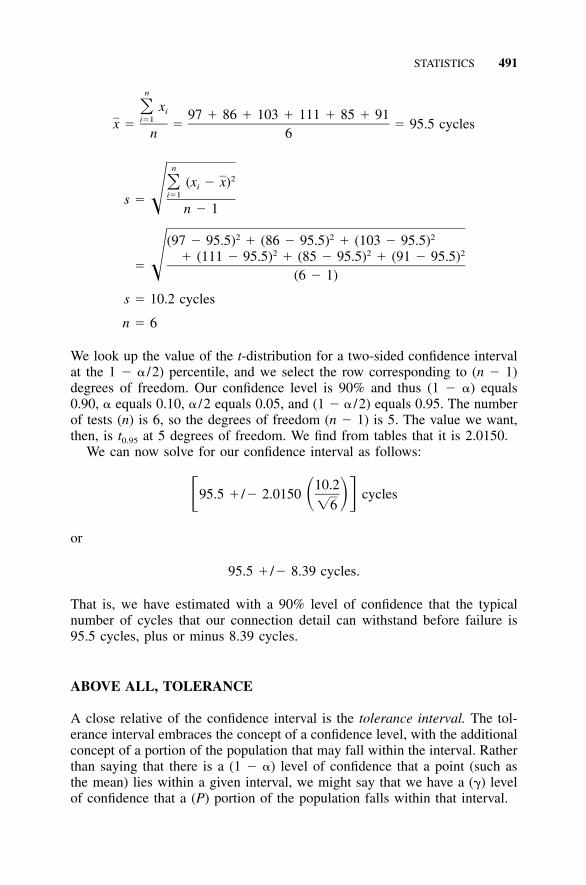
STATISTICS 491
n
x� i 97 � 86 � 103 � 111 � 85 � 91i�1x � � � 95.5 cyclesn 6
n2(x � x)� i
i�1s � � n � 1
2 2 2(97 � 95.5) � (86 � 95.5) � (103 � 95.5)2 2 2� (111 � 95.5) � (85 � 95.5) � (91 � 95.5)
� � (6 � 1)
s � 10.2 cycles
n � 6
We look up the value of the t-distribution for a two-sided confidence intervalat the 1 � � /2) percentile, and we select the row corresponding to (n � 1)degrees of freedom. Our confidence level is 90% and thus (1 � �) equals0.90, � equals 0.10, � /2 equals 0.05, and (1 � � /2) equals 0.95. The numberof tests (n) is 6, so the degrees of freedom (n � 1) is 5. The value we want,then, is t0.95 at 5 degrees of freedom. We find from tables that it is 2.0150.
We can now solve for our confidence interval as follows:
10.295.5 � /� 2.0150 cycles� � ���6
or
95.5 � /� 8.39 cycles.
That is, we have estimated with a 90% level of confidence that the typicalnumber of cycles that our connection detail can withstand before failure is95.5 cycles, plus or minus 8.39 cycles.
ABOVE ALL, TOLERANCE
A close relative of the confidence interval is the tolerance interval. The tol-erance interval embraces the concept of a confidence level, with the additionalconcept of a portion of the population that may fall within the interval. Ratherthan saying that there is a (1 � �) level of confidence that a point (such asthe mean) lies within a given interval, we might say that we have a (�) levelof confidence that a (P) portion of the population falls within that interval.
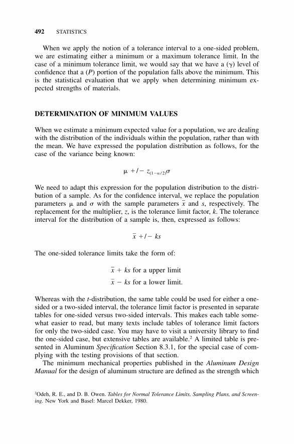
492 STATISTICS
When we apply the notion of a tolerance interval to a one-sided problem,we are estimating either a minimum or a maximum tolerance limit. In thecase of a minimum tolerance limit, we would say that we have a (�) level ofconfidence that a (P) portion of the population falls above the minimum. Thisis the statistical evaluation that we apply when determining minimum ex-pected strengths of materials.
DETERMINATION OF MINIMUM VALUES
When we estimate a minimum expected value for a population, we are dealingwith the distribution of the individuals within the population, rather than withthe mean. We have expressed the population distribution as follows, for thecase of the variance being known:
� � /� z �(1�� / 2)
We need to adapt this expression for the population distribution to the distri-bution of a sample. As for the confidence interval, we replace the populationparameters � and � with the sample parameters and s, respectively. Thexreplacement for the multiplier, z, is the tolerance limit factor, k. The toleranceinterval for the distribution of a sample is, then, expressed as follows:
x � /� ks
The one-sided tolerance limits take the form of:
x � ks for a upper limit
x � ks for a lower limit.
Whereas with the t-distribution, the same table could be used for either a one-sided or a two-sided interval, the tolerance limit factor is presented in separatetables for one-sided versus two-sided intervals. This makes each table some-what easier to read, but many texts include tables of tolerance limit factorsfor only the two-sided case. You may have to visit a university library to findthe one-sided case, but extensive tables are available.2 A limited table is pre-sented in Aluminum Specification Section 8.3.1, for the special case of com-plying with the testing provisions of that section.
The minimum mechanical properties published in the Aluminum DesignManual for the design of aluminum structure are defined as the strength which
2Odeh, R. E., and D. B. Owen. Tables for Normal Tolerance Limits, Sampling Plans, and Screen-ing. New York and Basel: Marcel Dekker, 1980.
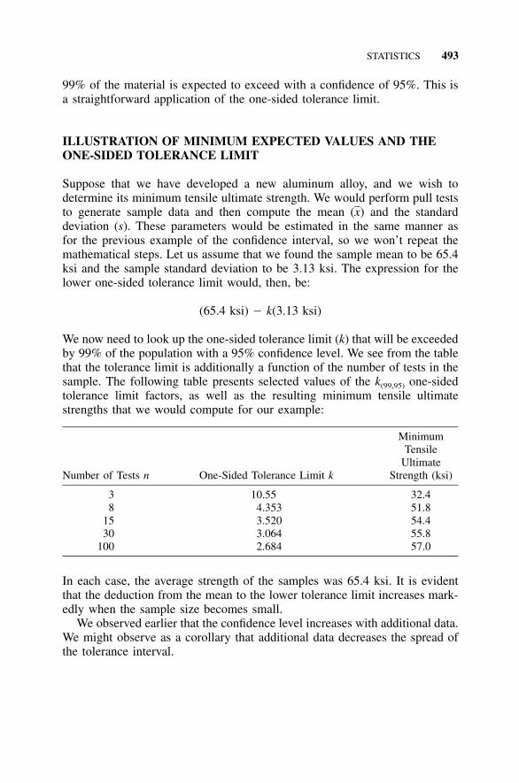
STATISTICS 493
99% of the material is expected to exceed with a confidence of 95%. This isa straightforward application of the one-sided tolerance limit.
ILLUSTRATION OF MINIMUM EXPECTED VALUES AND THEONE-SIDED TOLERANCE LIMIT
Suppose that we have developed a new aluminum alloy, and we wish todetermine its minimum tensile ultimate strength. We would perform pull teststo generate sample data and then compute the mean ) and the standard(xdeviation (s). These parameters would be estimated in the same manner asfor the previous example of the confidence interval, so we won’t repeat themathematical steps. Let us assume that we found the sample mean to be 65.4ksi and the sample standard deviation to be 3.13 ksi. The expression for thelower one-sided tolerance limit would, then, be:
(65.4 ksi) � k(3.13 ksi)
We now need to look up the one-sided tolerance limit (k) that will be exceededby 99% of the population with a 95% confidence level. We see from the tablethat the tolerance limit is additionally a function of the number of tests in thesample. The following table presents selected values of the k(99,95) one-sidedtolerance limit factors, as well as the resulting minimum tensile ultimatestrengths that we would compute for our example:
Number of Tests n One-Sided Tolerance Limit k
MinimumTensile
UltimateStrength (ksi)
3 10.55 32.48 4.353 51.8
15 3.520 54.430 3.064 55.8
100 2.684 57.0
In each case, the average strength of the samples was 65.4 ksi. It is evidentthat the deduction from the mean to the lower tolerance limit increases mark-edly when the sample size becomes small.
We observed earlier that the confidence level increases with additional data.We might observe as a corollary that additional data decreases the spread ofthe tolerance interval.

495
APPENDIX NTechnical Organizations
Aluminum Association (AA)900 19th Street, N.W., Suite 300Washington, DC 20006202-862-5100, 301-645-0756 (publications)202-862-5164 (fax)www.aluminum.orgThe Aluminum Association, founded in 1933, represents aluminum primaryproducers, recyclers, and producers of semi-fabricated products. The Alumi-num Association is the main source of information, standards, and statisticsconcerning the U.S. aluminum industry.
Aluminum Association of Florida (AAF)Association Headquarters1650 S. Dixie Highway, Suite 500Boca Raton, FL 33432561-362-9019561-395-8557 (fax)www.aaof.orgThe Aluminum Association of Florida is a trade association for aluminumconstruction contractors and fabricators and their suppliers.
Aluminum Extruders’ Council (AEC)1000 N. Rand Road, Suite 214Wauconda, IL 60084847-526-2010847-526-3993 (fax)www.aec.orgThe Aluminum Extruders Council, founded in 1950, is an international as-sociation of aluminum extruders. Most North American extruders are mem-bers, representing nearly 200 plants and nearly 100 companies.
American Architectural Manufacturers Association (AAMA)1827 Walden Office Square, Suite 104Schaumberg, IL 60173-4268847-303-5664
496 TECHNICAL ORGANIZATIONS
847-303-5774 (fax)www.aamanet.orgThe American Architectural Manufacturers Association is a trade associationfor the windows, doors, and skylights industry.
American Association of State Highway and Transportation Officials(AASHTO)444 North Capital Street, N.W., Suite 249Washington, DC 20001202-624-5800, 800-231-3475 (publications)202-624-5806 (fax)www.transportation.org
American Concrete Institute (ACI)P.O. Box 9094Farmington Hills, MI 48333-9094248-848-3800248-848-3801 (fax)www.aci-int.orgThe American Concrete Institute is a technical and educational society ded-icated to improving the design, construction, manufacture, and maintenanceof concrete structures.
American Galvanizers Association (AGA)6881 South Holly Circle, Suite 108Englewood, CO 80112800-468-7732720-554-0909 (fax)www.galvanizeit.orgThe American Galvanizers Association is a not-for-profit trade associationwhose members represent the after-fabrication, hot-dip galvanizing industrythroughout the U.S., Canada, and Mexico.
American Institute of Steel Construction (AISC)One East Wacker Drive, Suite 3100Chicago, IL 60601-2001312-670-2400, 800-644-2400 (publications)312-670-5403 (fax)www.aisc.orgThe American Institute of Steel Construction serves the structural steel in-dustry in the U.S. Its purpose is to expand the use of fabricated structuralsteel through research, education, technical assistance, standardization, andquality control.
American Iron and Steel Institute (AISI)1101 17th Street, N.W., Suite 1300
TECHNICAL ORGANIZATIONS 497
Washington, DC 20036202-452-7100, 800-277-3850 (publications)www.steel.org
American National Standards Institute (ANSI)1819 L Street, NW, 6th FloorWashington, DC, 20036202-293-8020202-293-9287 (fax)www.ansi.org
American Petroleum Institute (API)1220 L Street, N.W.Washington, DC 20005202-682-8000www.api.org
American Society of Civil Engineers (ASCE)1801 Alexander Bell DriveReston, VA 20191-4400800-548-2723www.asce.org
American Society of Mechanical Engineers (ASME)Three Park AvenueNew York, NY 10016-5990212-591-7722, 800-843-2763 (publications)212-591-7674 (fax)www.asme.org
American Society for Testing and Materials (ASTM)100 Barr Harbor DriveWest Conshohocken, PA 19428-2959610-832-9585610-832-9555 (fax)www.astm.org
American Welding Society (AWS)550 N.W. LeJeune RoadMiami, FL 33126800-443-9353 or 305-443-9353305-443-7559 (fax)www.amweld.org
ASM InternationalMaterials Park, OH 44073-0002
498 TECHNICAL ORGANIZATIONS
800-336-5152440-338-4634 (fax)www.asminternational.orgASM International serves the technical interests of metals and materialsprofessionals.
Building Officials and Code Administrators (BOCA)4051 West Flossmoor RoadCountry Club Hills, IL 60478708-799-2300708-799-4981 (fax)www.bocai.orgBuilding Officials and Code Administrators developed the model buildingcodes used primarily in the northeastern part of the U.S. prior to the devel-opment of the International Building Code.
Canadian Standards Association (CSA)178 Rexdale Boulevard.Toronto, Ontario, Canada M9W 1R3416-747-4000, 800-463-6727416-747-4149 (fax)www.csa.ca
Industrial Fastener Institute (IFI)1717 East Ninth Street, Suite 1105Cleveland, OH 44114-2879216-241-1482216-241-5901 (fax)www.industrial-fasteners.org
International Code Council (ICC)5203 Leesburg Pike, Suite 600Falls Church, VA 22041703-931-4533703-379-1546 (fax)www.intlcode.orgThe International Code Council was established in 1994 as a nonprofit or-ganization dedicated to developing a single set of comprehensive and co-ordinated national model construction codes. The founders of the ICC areBuilding Officials and Code Administrators International, Inc. (BOCA), In-ternational Conference of Building Officials (ICBO), and Southern BuildingCode Congress International, Inc. (SBCCI).
International Conference of Building Officials (ICBO)5360 Workman Mill RoadWhittier, CA 90601
TECHNICAL ORGANIZATIONS 499
310-699-0541310-692-3853 (fax)www.icbo.orgThe International Conference of Building Officials developed the model build-ing codes used primarily in the western part of the U.S. prior to the devel-opment of the International Building Code.
Metal Building Manufacturers Association (MBMA)1300 Sumner AvenueCleveland, OH 44115-2851216-241-7333216-241-0105 (fax)www.mbma.com
Metal Construction Association (MCA)104 South Michigan Avenue, Suite 1500Chicago, IL 60603312-201-0193www.mca1.orgFounded in 1983, the MCA seeks to expand the use of metal in constructionthrough marketing, technology, and education.
National Association of Aluminum Distributors (NAAD)1900 Arch StreetPhiladelphia, PA 19103-1498215-564-3484215-963-9784 (fax)www.naad.orgThe National Association of Aluminum Distributors is a trade association ofthe North American Service Centers and principal suppliers engaged in mar-keting aluminum products.
National Association of Architectural Metal Manufacturers (NAAMM)8 South Michigan Avenue, Suite 1000Chicago, IL 60603312-332-0405312-332-0706 (fax)www.naamm.orgThe National Association of Architectual Metal Manufacturers is a trade as-sociation representing manufacturers of metal products used chiefly in com-mercial and industrial building construction. These products include metalstairs and railings, flagpoles, expanded metal, hollow metal doors and frames,steel and aluminum bar grating, and metal lathing and furring.
National Association of Corrosion Engineers (NACE)1440 S. Creek Drive
500 TECHNICAL ORGANIZATIONS
Houston, TX 77084-4906281-228-6200www.nace.org
National Fire Protection Association (NFPA)1 Batterymarch ParkP.O. Box 9101Quincy, MA 02269-9101617-770-3000, 800-344-3555 (publications)617-770-0700 (fax)www.nfpacatalog.org
Non-Ferrous Founders’ Society (NFFS)1480 Renaissance Drive, Suite 310Park Ridge, IL 60068847-299-0950www.nffs.orgThe Non-Ferrous Founders’ Society represents the non-ferrous metal castingindustry.
Research Council on Structural Connections (RCSC)www.boltcouncil.orgThe Research Council on Structural Connections’ purpose is to support in-vestigations of the suitability and strength of structural connections, to pro-mote the knowledge of economical and efficient practices relating to suchstructural connections, and to publish standards and other documents neces-sary to achieving its purpose. The primary document the Council publishesis the Specification for Structural Joints Using ASTM A325 or A490 Bolts.
Society of Automotive Engineers (SAE)400 Commonwealth DriveWarrendale, PA 15096-0001724-776-4841, 877-606-7323724-776-5760 (fax)www.sae.org
The Society for Protective Coatings (SSPC)40 24th Street, 6th FloorPittsburgh, PA 15222-4656877-281-7772412-281-9992 (fax)www.sspc.orgThe Society for Protective Coatings was founded in 1950 as the Steel Struc-tures Painting Council, a professional society concerned with the use of coat-ings to protect industrial steel structures.
TECHNICAL ORGANIZATIONS 501
Southern Building Codes Congress International (SBCCI)900 Montclair RoadBirmingham, AL 35213205-591-1853205-592-7001 (fax)www.sbcci.orgThe Southern Building Codes Congress International developed the modelbuilding codes used primarily in the southeastern part of the U.S. prior to thedevelopment of the International Building Code.
Specialty Steel Industry of North America (SSINA)3050 K Street, N. W.Washington, DC 20007202-342-8630, 800-982-0355202-342-8631 (fax)www.ssina.comThe Specialty Steel Industry of North America is a voluntary trade associationrepresenting almost all the producers of specialty steel in North America.Members make a variety of products, including bar, rod, wire, angles, plate,sheet and strip, in stainless steel and other specialty steels.
Structural Stability Research Council (SSRC)University of FloridaDepartment of Civil EngineeringP.O. Box 116580Gainesville, FL 32611-6580352-846-3874352-846-3978 (fax)www.ce.ufl.eduThe Structural Stability Research Council, formerly the Column ResearchCouncil, publishes the Guide to Stability Design Criteria for Metal Structures.

503
GLOSSARY
The definitions in this glossary are based on usage common in the aluminumindustry. Terms italicized in the text and in these definitions are defined here.
alclad: an adjective applied to aluminum alloys given a thin aluminum oraluminum alloy coating metallurgically bonded to the surface. This coatingelectrolytically protects the core alloy against corrosion in a manner similarto the way zinc galvanizing protects steel.
allowable stress: a stress to which stresses produced by nominal loads arelimited in allowable stress design.
allowable stress design (ASD): a method of proportioning structural com-ponents that limits stresses under nominal loads to the yield or ultimatestrength divided by a safety factor.
alloy: a material with metallic properties and composed of two or more el-ements, at least one of which is a metal.
aluminum: a silvery, lightweight, easily worked metallic element resistant tocorrosion and abundant in nature; its atomic number is 13. Commerciallypure aluminum (99% or greater) is designated by an alloy number of 1xxx.
Aluminum Specification: the 7th edition of the Specification for AluminumStructures published by the Aluminum Association (AA).
anchor bolt: a bolt used to anchor members to a foundation.annealing: a thermal treatment that reduces the yield strength and softens a
metal by relieving stresses induced by cold work or by coalescing precip-itates from solid solution.
anodizing: forming an oxide coating on a metal by electrochemical treatment.artificial aging: a rapid precipitation from solid solution at elevated temper-
atures to produce a change in mechanical properties. Tempers T5 throughT10 are artificially aged.
ASD: see allowable stress design.aspect ratio: the ratio of width to thickness for a rectangular plate element.austenitic stainless steel: AISI 200 Series (chromium, nickel, and manganese
alloys) and AISI 300 Series (chromium and nickel) stainless steels. Thesesteels are nonmagnetic.
bar: a solid wrought product with a cross-section square or rectangular or aregular hexagon or octagon and which may have rounded corners, and withat least one perpendicular distance between parallel faces of 0.375 in. ormore [more than 10 mm]. See Table G.1.
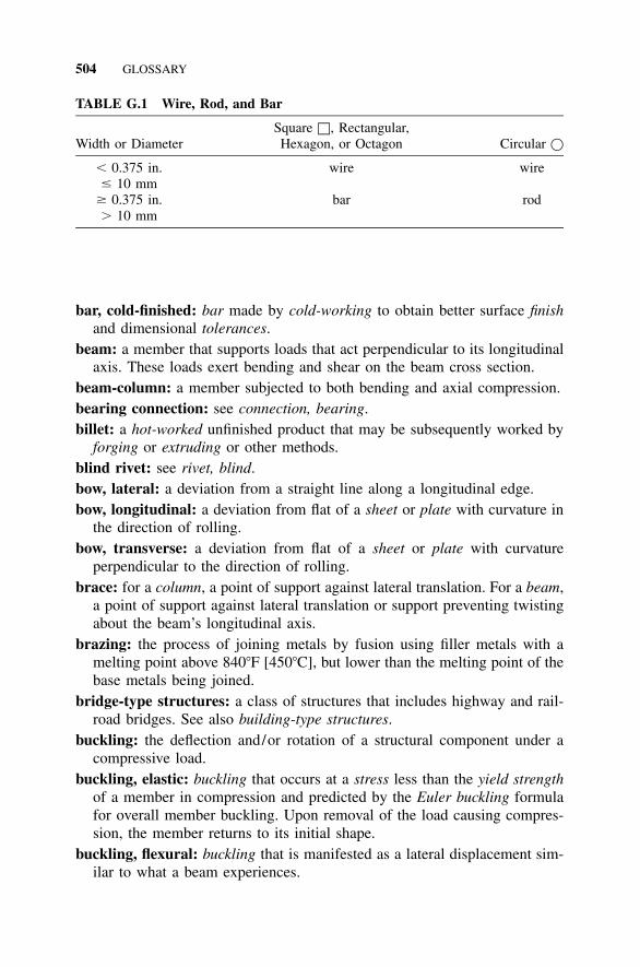
504 GLOSSARY
TABLE G.1 Wire, Rod, and Bar
Width or DiameterSquare □, Rectangular,Hexagon, or Octagon Circular �
� 0.375 in.� 10 mm
wire wire
� 0.375 in.� 10 mm
bar rod
bar, cold-finished: bar made by cold-working to obtain better surface finishand dimensional tolerances.
beam: a member that supports loads that act perpendicular to its longitudinalaxis. These loads exert bending and shear on the beam cross section.
beam-column: a member subjected to both bending and axial compression.bearing connection: see connection, bearing.billet: a hot-worked unfinished product that may be subsequently worked by
forging or extruding or other methods.blind rivet: see rivet, blind.bow, lateral: a deviation from a straight line along a longitudinal edge.bow, longitudinal: a deviation from flat of a sheet or plate with curvature in
the direction of rolling.bow, transverse: a deviation from flat of a sheet or plate with curvature
perpendicular to the direction of rolling.brace: for a column, a point of support against lateral translation. For a beam,
a point of support against lateral translation or support preventing twistingabout the beam’s longitudinal axis.
brazing: the process of joining metals by fusion using filler metals with amelting point above 840�F [450�C], but lower than the melting point of thebase metals being joined.
bridge-type structures: a class of structures that includes highway and rail-road bridges. See also building-type structures.
buckling: the deflection and/or rotation of a structural component under acompressive load.
buckling, elastic: buckling that occurs at a stress less than the yield strengthof a member in compression and predicted by the Euler buckling formulafor overall member buckling. Upon removal of the load causing compres-sion, the member returns to its initial shape.
buckling, flexural: buckling that is manifested as a lateral displacement sim-ilar to what a beam experiences.
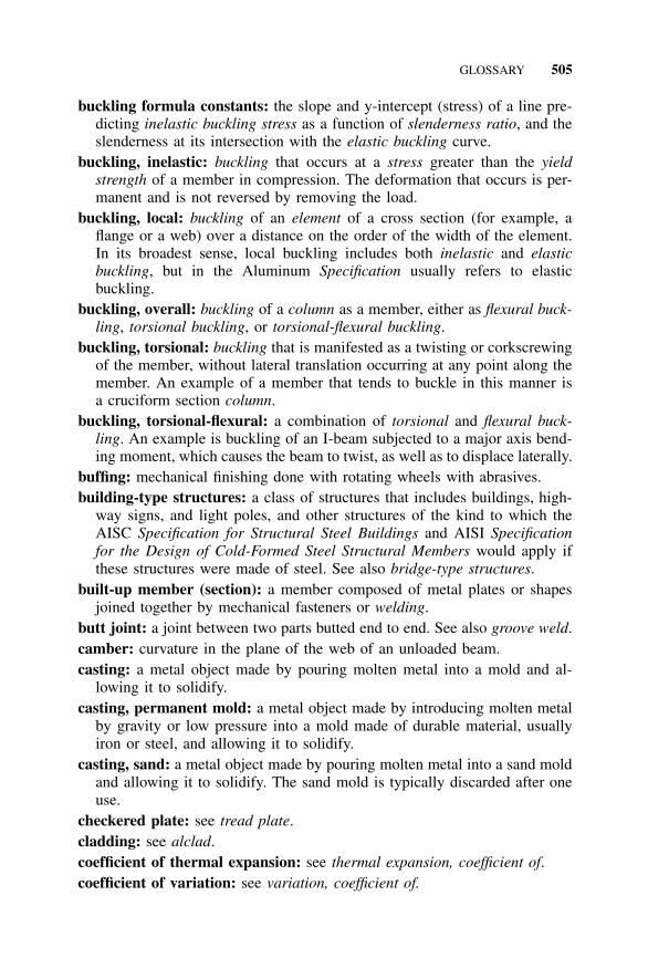
GLOSSARY 505
buckling formula constants: the slope and y-intercept (stress) of a line pre-dicting inelastic buckling stress as a function of slenderness ratio, and theslenderness at its intersection with the elastic buckling curve.
buckling, inelastic: buckling that occurs at a stress greater than the yieldstrength of a member in compression. The deformation that occurs is per-manent and is not reversed by removing the load.
buckling, local: buckling of an element of a cross section (for example, aflange or a web) over a distance on the order of the width of the element.In its broadest sense, local buckling includes both inelastic and elasticbuckling, but in the Aluminum Specification usually refers to elasticbuckling.
buckling, overall: buckling of a column as a member, either as flexural buck-ling, torsional buckling, or torsional-flexural buckling.
buckling, torsional: buckling that is manifested as a twisting or corkscrewingof the member, without lateral translation occurring at any point along themember. An example of a member that tends to buckle in this manner isa cruciform section column.
buckling, torsional-flexural: a combination of torsional and flexural buck-ling. An example is buckling of an I-beam subjected to a major axis bend-ing moment, which causes the beam to twist, as well as to displace laterally.
buffing: mechanical finishing done with rotating wheels with abrasives.building-type structures: a class of structures that includes buildings, high-
way signs, and light poles, and other structures of the kind to which theAISC Specification for Structural Steel Buildings and AISI Specificationfor the Design of Cold-Formed Steel Structural Members would apply ifthese structures were made of steel. See also bridge-type structures.
built-up member (section): a member composed of metal plates or shapesjoined together by mechanical fasteners or welding.
butt joint: a joint between two parts butted end to end. See also groove weld.camber: curvature in the plane of the web of an unloaded beam.casting: a metal object made by pouring molten metal into a mold and al-
lowing it to solidify.casting, permanent mold: a metal object made by introducing molten metal
by gravity or low pressure into a mold made of durable material, usuallyiron or steel, and allowing it to solidify.
casting, sand: a metal object made by pouring molten metal into a sand moldand allowing it to solidify. The sand mold is typically discarded after oneuse.
checkered plate: see tread plate.cladding: see alclad.coefficient of thermal expansion: see thermal expansion, coefficient of.coefficient of variation: see variation, coefficient of.
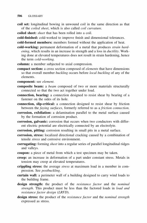
506 GLOSSARY
coil set: longitudinal bowing in unwound coil in the same direction as thatof the coiled sheet, which is also called coil curvature.
coiled sheet: sheet that has been rolled into a coil.cold-finished: cold-worked to improve finish and dimensional tolerances.cold-formed members: members formed without the application of heat.cold-working: permanent deformation of a metal that produces strain hard-
ening, which results in an increase in strength and a loss in ductility. Work-ing done at elevated temperatures does not result in strain hardening, hencethe term cold-working.
column: a member subjected to axial compression.compact section: a cross section composed of elements that have dimensions
so that overall member buckling occurs before local buckling of any of theelements.
component: see element.composite beam: a beam composed of two or more materials structurally
connected so that the two act together under load.connection, bearing: a connection designed to resist shear by bearing of a
fastener on the sides of its hole.connection, slip-critical: a connection designed to resist shear by friction
between the faying surfaces, formerly referred to as a friction connection.corrosion, exfoliation: a delamination parallel to the metal surface caused
by the formation of corrosion product.corrosion, galvanic: corrosion that occurs when two conductors with differ-
ent electric potential are electrically connected by an electrolyte.corrosion, pitting: corrosion resulting in small pits in a metal surface.corrosion, stress: localized directional cracking caused by a combination of
tensile stress and corrosive environment.corrugating: forming sheet into a regular series of parallel longitudinal ridges
and valleys.coupon: a piece of metal from which a test specimen may be taken.creep: an increase in deformation of a part under constant stress. Metals in
tension may creep at elevated temperatures.crippling stress: the average stress at maximum load in a member in com-
pression. See postbuckling.curtain wall: a perimeter wall of a building designed to carry wind loads to
the building frame.design strength: the product of the resistance factor and the nominal
strength. This product must be less than the factored loads in load andresistance factor design (LRFD).
design stress: the product of the resistance factor and the nominal strengthexpressed as stress.
GLOSSARY 507
diaphragm: a flat element that resists shear loads acting in its own plane.doubly symmetric section: a cross section that is symmetric about each of
two and only two perpendicular axes, for example, an Aluminum Associ-ation standard I-beam.
draft: taper on the sides of a die or mold to allow removal of forgings,castings, or patterns from the die or mold.
drawing: pulling material through a die to reduce its size, change its crosssection, or harden it.
ductility: the ability of a material to withstand plastic strain before rupture.A comparison of the modulus of resilience to the modulus of toughness isa measure of ductility.
duralumin: name used for the early aluminum-copper alloys that turned outto be not very durable.
dye penetrant testing: an inspection method that uses a penetrating dye oroil for the detection of surface cracks or defects.
edge stiffener: see stiffener, edge.effective length: see length, effective.effective net area: see net area, effective.effective width: see width, effective.elastic: pertaining to the behavior of material under load at stresses below
the proportional limit, where deformations under load are not permanent.elastic analysis: determination of the effects of loads on members based on
the assumption that the member behavior is elastic.elastic buckling: see buckling, elastic.elastically supported flange: see flange, elastically supported.element: a plate, either rectangular or curved in cross section and connected
to other elements only along its longitudinal edges to other elements. SeeFigure 5.6 for examples. In the Aluminum Specification, elements ofshapes are also called components of shapes.
elongation: the percentage increase in the distance between two gauge marksof a specimen tensile-tested to rupture. The elongation is dependent on theoriginal gauge length (2 in. [50 mm] is often used), and original dimen-sions, such as thickness, of the specimen. Elongation is considered to givea general indication of ductility.
embossing: a raised relief pattern on a surface, typically used on aluminumsheet to enhance appearance, also called patterned sheet.
endurance limit: the fatigue strength of a plain specimen for a very largenumber of cycles (500,000,000) of stress reversals, measured by a standardtest. For this constant amplitude loading, the fatigue strength will be noless than the endurance limit, even at a greater number of cycles. See alsofatigue limit.
508 GLOSSARY
Euler buckling stress: the elastic buckling stress of a column predicted byEuler’s formula �2E / (L /r)2. See also buckling, elastic.
exfoliation: see corrosion, exfoliation.extrusion: a product made by pushing material through an opening called a
die.extrusion billet: a solid or hollow stock, commonly cylindrical, charged into
an extrusion press.failure mode: see limit state.fatigue: fracture caused by the repeated application of stresses.fatigue limit: the allowable stress range for a structural component subjected
to 5 million cycles of constant amplitude cyclic load, as calculated byEquation 4.8.1-2 in the Aluminum Specification. See also endurance limit.
faying surface: either of the adjacent surfaces held closely together in a joint.filler wire: see weld filler wire.fillet: a rounded corner.finish: the characteristics of a surface.first order analysis: analysis based on satisfying equilibrium conditions on
the undeflected structure.flange: (1) general use: a plate element of a shape, oriented parallel to the
bending axis and near the extreme fiber; (2) specific use in some provisionsof the Aluminum Specification: that portion of the cross section that liesmore than two-thirds the distance from the neutral axis to the extreme fiber.
flange, elastically supported: the flange that lies on the compression side ofthe neutral axis of a beam bent about its minor axis. An example is shownin Figure 10.11. The flange is said to be elastically supported because itstendency to buckle can be measured by a spring constant. A method forcalculating the strength of an elastically supported flange is given in theAluminum Specification Section 4.10.
flexural buckling: see buckling, flexural.flexure: bending.forging: a product worked to a predetermined shape using one or more pro-
cesses, such as hammering, upsetting, pressing, rolling, etc.fracture: a rupture or break due to the application of tension.fracture toughness: the ability to resist cracking at a notch or crack. See
also modulus of toughness and notch-sensitive.friction connection: see connection, slip-critical.galvanic corrosion: see corrosion, galvanic.gauge: a number designating the thickness of sheet, plate, or wire. Alter-
nately, the spacing between fasteners in a direction perpendicular to thedirection of force.
grip: the total thickness of parts joined by a fastener.
GLOSSARY 509
groove weld: a weld made at a butt joint and sometimes referred to as a buttweld. There are several kinds of groove welds, such as bevel, vee, J, andU welds; they may be the full depth or only a partial penetration of thethickness.
gross section or area: the full cross-sectional area less the area of holes notfilled with fasteners.
hard metric conversion: see metric conversion, hard.heat affected zone (HAZ): the region with reduced strength in the vicinity
of a weld, taken as 1 in. [25 mm] from the centerline of a groove weld orthe heel of a fillet weld according to the Aluminum Specification.
heat treating: obtaining desired properties by heating or cooling an alloyunder controlled conditions. This does not include heating solely to allowhot-working.
heat-treatable alloy: an alloy that may be heat-treated to increase strength.hot-rolled shapes: shapes formed by rolling when the metal is in a semi-
molten state.hot-working: plastic deformation at a temperature high enough that prevents
strain-hardening.inelastic: without return to original shape upon removal of load.inelastic buckling: see buckling, inelastic.intermediate stiffener: see stiffener, intermediate.lateral bow: deviation from straight of a longitudinal edge.length, effective: the length, equal to kL, over which a member would buckle
if it were pin-ended about the axis of buckling rotation.limit, proportional: see proportional limit.limit state: a design condition at which a structure or component becomes
unfit for service because it no longer performs its intended function (i.e.,it has reached its serviceability limit state), or it is unable to support loads(i.e., it has reached its strength limit state). Also referred to as a failuremode.
load and resistance factor design (LRFD): a method of proportioning struc-tural components using load factors and resistance factors so that no limitstate is exceeded when the structure is subjected to all appropriate loadcombinations. LRFD is also called strength design.
load factor (�): a factor applied to a nominal load to account for uncertaintiesin predicting it accurately.
local buckling: see buckling, local.lockbolt: a fastener composed of a pin and a collar, which is swaged onto a
series of concentric ridges on the pin during installation. (See Figure 8.5.)lot, heat-treat: material of the same mill form, alloy, temper, section, and
size traceable to one heat-treated furnace load or 8-hour period for contin-uous furnaces.
510 GLOSSARY
lot, inspection: an identifiable quantity of material submitted for inspectionat one time.
LRFD: see load and resistance factor design.mechanical properties: properties related to the behavior of material when
subjected to force, including modulus of elasticity, yield strength, ultimatestrength, and others.
mechanical properties, minimum: the mechanical properties which 99% ofthe material is expected to exceed at a confidence level of 0.95.
metric conversion, hard: conversion of foot-pound units to metric units andmodifying the result to an even, convenient round number in metric units.See metric conversion, soft.
metric conversion, soft: conversion of foot-pound units to metric units with-out modifying the result to an even, convenient round number in metricunits. See metric conversion, hard.
mill finish: the finish on material as produced by the mill without any addi-tional treatment.
minimum mechanical properties: see mechanical properties, minimum.modulus of elasticity (E): the slope of the stress-strain curve up to the pro-
portional limit, which is the linear part of the curve. The modulus, alsocalled Young’s Modulus, may be measured for tension or compression. Thecompressive modulus for various aluminum alloys is given in AluminumSpecification Table 3.3-1 and averages about 10,000 ksi [70,000 MPa].
modulus of resilience: the area under the linear portion of the stress-straincurve, considered to be a measure of the elastic strain energy of the ma-terial. See ductility and modulus of toughness.
modulus of rigidity (G): the ratio of shear stress in a torsion test to shearstrain in the elastic range, also called the shear modulus. An approximateaverage value for aluminum alloys is 3,800 ksi [26,000 MPa]. It can becalculated from the modulus of elasticity (E) and Poisson’s ratio by theformula G � E / (2[1 � v]).
modulus of toughness: the entire area under the stress-strain curve up torupture, considered to be a measure of the total strain energy the materialcan withstand before rupture. See ductility and modulus of resilience.
moment gradient: the variation of bending moment over the length of thebeam, a graph of which is called the moment diagram.
natural aging: the change in mechanical properties that takes place in heat-treatable aluminum alloys at ambient temperature over time due to theprecipitation of alloying elements from solid solution.
NDT: see nondestructive testing.net area: the area of a cross section exclusive of holes.net area, effective: the portion of the net area that may be used in calculating
tensile stress for a member in tension. Elements of the section that are not
GLOSSARY 511
connected at joints may not be fully effective in carrying tensile stress, sosuch elements may not be fully included in the net effective area.
neutral axis: the line of zero fiber stress in a section of a member in bending.nominal loads: the magnitude of loads as given in applicable codes before
any factors are applied.nominal strength: the load-carrying capacity of a structure or component as
determined by calculations using the minimum mechanical properties andrational analysis or by testing conducted in accordance with the AluminumSpecification.
non-compact section: a cross section with an element of dimensions so thatthe element’s strength is limited by inelastic buckling. In aluminum, suchan element has a slenderness ratio between slenderness limits S1 and S2.See also compact and slender element section.
nondestructive testing (NDT): tests that do not alter the mechanical prop-erties of the material inspected, sometimes referred to as nondestructiveexamination (NDE).
non-heat-treatable alloy: an alloy that can be strengthened only by cold-working.
notch-sensitive: a condition characterized by the ultimate stress on the netsection attained in tests of specimens with sufficiently sharp notches beingless than the specified minimum tensile yield strength. See also fracturetoughness.
open die: a die, usually for an extrusion, that is available for use by anycustomer without a die charge.
open section: a cross section that can be drawn by a single continuous line,such as a wide flange, channel, tee, zee, or angle.
overall buckling: see buckling, overall.penetrant testing: see dye penetrant testing.permanent mold casting: see casting, permanent mold.physical properties: properties of a material other than mechanical proper-
ties, such as density or electrical conductivity.pin: a fastener about whose axis connected parts are not substantially re-
strained from rotation.pipe: tube in standardized diameters and wall thicknesses given in an ANSI
standard by nominal diameter and schedule number.pitting: see corrosion, pitting.plastic: pertaining to behavior of aluminum under load at stresses above the
proportional limit, where deformations under load are permanent. Alsoreferred to as inelastic.
plastic design: a design method based on members having the ability tomaintain a full plastic moment through large rotations so that a mechanismcan develop, allowing moment redistribution.
512 GLOSSARY
plate: a rolled product with a rectangular cross section and thickness of atleast 0.25 in. [more than 6.3 mm] with sheared or sawed edges. The re-quirement for sheared or sawed edges distinguishes the product from anextrusion. See also sheet.
point symmetric section: a cross section that is symmetric about any axis inthe cross section drawn through a common point, for example, a cruciformor zee section with equal length legs.
Poisson’s ratio (�): the negative of the ratio of the transverse strain to thelongitudinal strain of a member subjected to axial force within the pro-portional limit. Poisson’s ratio for aluminum alloys is approximately 0.33.
ponding: the collecting of water in low areas on a roof.postbuckling: pertaining to behavior of an element in compression after elas-
tic buckling has occurred, referring to the ability of some structural com-ponents to sustain loads greater than the elastic buckling load. See crip-pling stress.
precipitation-heat treatment: artificial aging.prismatic: having a constant cross section with respect to length.profile: a wrought product much longer than its width other than sheet, plate,
rod, bar, tube, or wire. The term profile is preferred over ‘‘shape,’’ but theterms are synonymous.
profile, structural: a profile in standard alloys, tempers, sections, and di-mensions, such as angles, channels, I-beams, H-beams, tees, and zees, com-monly used for structural purposes. These are shown in Aluminum DesignManual, Part VI, Section Properties.
proportional limit: the stress at which the stress-strain curve begins to de-viate from a straight line.
pull-out force (Pnot): the force in the direction of the axis of a screw requiredto pull a screw out of the material into which it is threaded. See Figure8.18.
pull-over force (Pnov): the force in the direction of the axis of a screw requiredto pull the connected part under the head of the screw over the head. SeeFigure 8.18.
punching: forming a hole in metal by pushing a male die through the ma-terial, which is supported below by a female die of slightly largerdimensions.
purlin: a horizontal structural member that supports roofing.radiography: X-ray pictures.radius of gyration (r): the square root of the quantity obtained by dividing
the moment of inertia by the area of a cross section. The radius of gyrationis identified with respect to the axis about which the moment of inertia istaken.
GLOSSARY 513
radius of gyration, effective (rye): a distance that may be used instead ofradius of gyration to calculate the moment carrying capacity of a beam, orthe buckling load of a column.
rational analysis: prediction of load-carrying capacity using accepted prin-ciples of structural mechanics.
reaming: fabricating a hole to final size by enlarging a smaller hole.re-entrant cut: a cut into material similar to that shown in Figure 3.14.reliability index: a measure of the reliability of a structure equal to the
number (�) of standard deviations of the natural log of the R /Q distributionbetween the mean and zero (where R is the resistance and Q is the loadeffect).
residual stress: stress in an unloaded member after it has been formed. Re-sidual stresses may arise in aluminum members from welding, cold bend-ing, differential cooling after heating, finishing, and other fabricationmethods.
resilience, modulus of: see modulus of resilience.resistance factor: a factor less than one accounting for variations in material
properties, fabrication, and design, and the consequences of failure appliedto the nominal strength for load and resistance factor design.
ribbed siding: siding with a particular trapezoidal cross section with dimen-sions shown in Aluminum Design Manual, Part VI, Table 31.
rigidity, modulus of: see modulus of rigidity.rivet: a one-piece fastener that is deformed during installation to acquire its
final configuration.rivet, blind: a rivet that can be installed with access to only one side of the
parts being joined.rod: a solid wrought product circular in cross section with a diameter not
less than 0.375 in. [more than 10 mm]. See Table G.1.roll-forming: a fabrication method of forming parts with a constant cross
section and longitudinal bends using a series of cylindrical dies in male-female pairs to progressively form a sheet or plate to a final shape in acontinuous operation. For example, a corrugated sheet.
roofing: corrugated or folded sheet used to clad the roofs of buildings.rust: a form of corrosion product common to iron bearing materials. Rust
never sleeps.safety factor: a factor greater than one by which nominal strength is divided
to calculate allowable stress. Safety factors vary depending on the type ofaluminum structure (bridge or building), as well as the type of limit state(yielding or ultimate strength).
sand casting: see casting, sand.sandwich panel: a panel assembly consisting of an insulating core material
with aluminum skins on both sides. Also called aluminum composite ma-terial (ACM). See Section 3.1.5.
514 GLOSSARY
second-order analysis: analysis based on satisfying equilibrium conditionson the deflected structure.
self-drilling screw: a screw that drills and taps its own hole as it is beingdriven.
shape: see profile.shape factor: for bending, the ratio of the moment carried by a continuously
braced beam with the full section yielded to the moment carried by thebeam when yielding first occurs. The shape factor is a function of the shapeof the cross section, being higher for cross sections with more materialconcentrated near the neutral axis than for those sections with materialdispersed farther away from the neutral axis.
shear center: that point in the plane of a cross section through which trans-verse (shear) load must act to produce no twisting of the cross section.The shear center is also called the flexural center.
shear modulus: see modulus of rigidity.shear ultimate strength (Fsu): the maximum stress sustainable in shear.sheet: a rolled product with a rectangular cross section and a thickness less
than 0.25 in. and at least 0.006 in. [more than 0.15 mm through 6.3 mm]with slit, sheared, or sawed edges. The edge requirement is to distinguishthis product from extrusions. See also plate.
siding: corrugated or folded sheet used to clad building walls.singly symmetric section: a cross section that is symmetric about one and
only one axis. For example, an Aluminum Association standard channel.slender element section: a cross section with an element of dimensions so
that the element will undergo elastic buckling. In aluminum, such an ele-ment has a slenderness ratio greater than the S2 slenderness limit. See alsocompact and non-compact section.
slenderness limit (S1, S2): a slenderness ratio below which the compression-carrying capacity is predicted by one equation and above which the ca-pacity is predicted by another equation.
slenderness ratio: a measure of the tendency of a compression member tobuckle. For overall member buckling, this is the ratio of the effective lengthto radius of gyration, both with respect to the same axis. For local buckling,this is the ratio of width (or midthickness radius, for curved elements) ofan element to its thickness. See also aspect ratio.
soft metric conversion: see metric conversion, soft.space frame: a three-dimensional structural frame.spinning: a fabrication method of shaping material into a piece with an axis
of revolution in a spinning lathe with a mandrel.SSRC: see Structural Stability Research Council.stabilizing: a low-temperature heat treatment used to prevent age-softening
of certain strain-hardened aluminum alloys containing magnesium.
GLOSSARY 515
stainless steel: alloys of iron containing 10.5% or more chromium. Standardsfor the design of stainless steel structural members are provided in ASCEStandard 8-90, Specification for the Design of Cold-Formed Stainless SteelStructural Members (82). See also austenitic stainless steel.
standard deviation: in statistics, a measure of variability equal to the squareroot of the arithmetic average of the squares of the deviations from themean in a frequency distribution.
standing seam: a seam, usually between roofing sheets, made by fitting to-gether the upturned legs of two adjacent pieces. See Figure 10.2.
steel: an alloy of iron with a small quantity of carbon and other elements.Synonym: an archaic metal that rusts.
Steel Manual: the 9th edition (1989) of the Manual of Steel Constructionpublished by the AISC and which includes the Specification for StructuralSteel Buildings, Allowable Stress Design (39).
stiffener: material added to a flat element of a cross section to increase itscapacity to carry compression.
stiffener, edge: a stiffener along the free edge of an element.stiffener, intermediate: a stiffener not located along the edge of an element.strain (�): the deformation of a member under load, referred to its original
dimensions. For example, the elongation per unit length is a tensile strain.strain hardening: cold-working that results in an increase in strength and
loss of ductility.strength design: see load and resistance factor design.strength, nominal: see nominal strength.stress (ƒ): force divided by area.Structural Stability Research Council (SSRC): Formerly the Column Re-
search Council, this organization fosters research on the behavior of com-pressive components of metal structures and writes the Guide to StabilityDesign Criteria for Metal Structures (107). In the 4th edition of the Guide,Section 3.9 discusses aluminum columns.
stub column: a full cross-section compression test specimen short enough sothat it will not buckle elastically or inelastically as a column.
supported: for plate elements, the condition of an edge that is continuouslyattached to another plate element. For members, the condition at the endof the member that prevents transverse displacement but permits rotationand longitudinal displacement.
tangent modulus of elasticity (Et): the slope of the stress-strain curve beyondthe proportional limit. This slope varies depending on the strain.
tapping screw: a screw that taps a predrilled hole as it is being driven.temper: a condition produced by mechanical or thermal treatment.tensile ultimate strength: see ultimate strength.
516 GLOSSARY
tensile yield strength: see yield strength.tension field action: postbuckling behavior of an element in shear, such as
the web of a beam, that demonstrates diagonal buckling waves, and bywhich tension is carried by diagonal bands and compression by verticalstiffeners, like a truss.
thermal expansion, coefficient of (�): the measure of the change in strainin a material caused by a change in temperature. This physical property isa function of alloy and temperature range, and is approximately 13 � 10�6
per �F [23 � 10�6 per �C] for aluminum alloys.tolerance: an allowable deviation from a nominal or specified dimension or
property.torsion constant (J): a measure of the stiffness of a section in pure twisting,
in units of length to the fourth power.torsional buckling: see buckling, torsional.torsional-flexural buckling: see buckling, torsional-flexural.toughness, modulus of: see modulus of toughness.trapezoidal sheet: sheet that has been formed by bending to have a cross
section similar to that shown in Figure 10.1. Aluminum Design Manual,Part VI, Table 31 shows examples of trapezoidal sheet called ribbed sidingand V-beam roofing and siding.
tread plate: sheet or plate with a raised diamond pattern on one side for slip-resistance. Also called checkered plate or diamond plate. See Section 3.1.5.
tube: a hollow wrought product that is longer than its width, is symmetricaland round, hexagonal, octagonal, elliptical, square, or rectangular, and hasuniform wall thickness.
ultimate strength: the maximum strength a material can withstand beforerupture. Two ultimate strengths exist for each alloy and temper: tension(Ftu) and shear (Fsu).
V-beam: roofing or siding with a particular trapezoidal cross section withdimensions shown in Aluminum Design Manual, Part VI, Table 31.
variation, coefficient of: in statistics, the ratio of the standard deviation tothe mean.
warping: distortion of a member’s cross section from a flat plane.warping constant (Cw): a measure of the resistance to rotation that arises
because of restraint of warping of the cross section, in units of length tothe sixth power. Formulas for warping constants for various cross sectionscan be found in Sharp (Table 5.6) (133) and the Aluminum Design Manual,Part VI, Table 29.
water staining: oxidation of an aluminum surface in the presence of waterbetween two closely held metal surfaces.
web: a connecting element between flanges.web crippling: local buckling of a web at a point of support or concentrated
load.
GLOSSARY 517
weld filler wire: wire used as filler metal in welds, also called weld wire.Recommended filler alloys for various combinations of alloys to be weldedtogether are given in Aluminum Specification Table 7.2-1.
welded tube: tube produced by longitudinally forming and seam-weldingsheet.
welding: joining pieces by applying heat, with or without filler metal, to unitethe pieces by fusion.
width, effective (be): that portion of the width of an element in compressionover which an assumed uniform stress will predict the same behavior (suchas deflection and strength) as produced by the actual nonuniform stressdistribution. The portion of the element not included in the effective widthmay be considered to be buckled and supporting no load.
wire: a solid wrought product whose diameter or greatest perpendicular dis-tance between parallel faces is less than 0.375 in. [less than or equal to 10mm], with a round, square, rectangular, or regular octagon or hexagon crosssection. See Table G.1.
working: deforming a metal by mechanical action, such as rolling, extruding,or forging.
working load: a load, such as snow load or wind load, as given by theappropriate code or specification, without any factors applied.
wrought products: products that have been mechanically worked by a pro-cess, such as rolling, extruding, forging, or drawing.
yield strength: the stress at and above which loading causes permanent de-formation. In aluminum, this is measured by the 0.2% offset method: Aline is drawn parallel to the linear portion of the stress-strain curve andthrough 0.2% strain, and the yield strength is taken as the stress at theintersection of this line and the stress-strain curve. Three yield strengthsexist for each alloy and temper: one for each type of stress (compression(Fcy), tension (Fty), and shear (Fsy)).
yielding: deforming permanently.Young’s modulus: See modulus of elasticity.

519
REFERENCES
1. Alcoa, Alcoa Structural Handbook, Pittsburgh, PA, 1960.2. Aluminum Association, Aluminum Alloys for Cryogenic Applications, Washing-
ton, DC, 1999.3. Aluminum Association, Aluminum Automotive Extrusion Manual AT6, Washing-
ton, DC, 1998.4. Aluminum Association, Aluminum Design Manual, Washington, DC, 2000.5. Aluminum Association, Aluminum Drainage Products Manual, Washington, DC,
1983.6. Aluminum Association, Aluminum for Automotive Body Sheet Panels AT3, Wash-
ington, DC, 1996.7. Aluminum Association, Aluminum Forging Design Manual, 2nd edition, Wash-
ington, DC, October 1995.8. Aluminum Association, Aluminum Forgings Application Guide, Washington, DC,
1st edition, November 1975.9. Aluminum Association, Aluminum in Building and Construction, Washington,
DC, undated.10. Aluminum Association, Aluminum Standards and Data 1998 Metric SI, Wash-
ington, DC, April 1998.11. Aluminum Association, Aluminum Standards and Data 2000, Washington, DC,
June 2000.12. Aluminum Association, Automotive Aluminum Crash Energy Management Man-
ual AT5, Washington, DC, 1998.13. Aluminum Association, Commentary on Specifications for Aluminum Structures,
2nd edition, Washington, DC, December 1982.14. Aluminum Association, Designation System for Aluminum Finishes, 7th edition,
Washington, DC, September 1980; reaffirmed 1993.15. Aluminum Association, Engineering Data for Aluminum Structures, 5th edition,
Washington, DC, December 1986.16. Aluminum Association, Fire Resistance and Flame Spread Performance of Alu-
minum and Aluminum Alloys, Washington, DC, 1997.17. Aluminum Association, Guidelines for Minimizing Water Staining of Aluminum,
AA TR3, 3rd edition, Washington, DC, 1990.18. Aluminum Association, Guidelines for the Use of Aluminum with Food and
Chemicals, Washington, DC, 1994.19. Aluminum Association, International Alloy Designations and Chemical Com-
position Limits for Wrought Aluminum and Wrought Aluminum Alloys, Washing-ton, DC, 2001.
520 REFERENCES
20. Aluminum Association, Metalworking with Aluminum, 2nd edition, Washington,DC, December 1975.
21. Aluminum Association, Specifications for Aluminum Sheet Metal Work in Build-ing Construction, 4th edition, Washington, DC, October 2000.
22. Aluminum Association, Specifications for Aluminum Structures, 5th edition,Washington, DC, December 1986.
23. Aluminum Association, Standards for Aluminum Sand and Permanent MoldCastings, 14th edition, Washington, DC, March 2000.
24. Aluminum Association, Structural Design with Aluminum, 1st edition, Washing-ton, DC, May 1987.
25. Aluminum Association, Tempers for Aluminum and Aluminum Alloy Products,Washington, DC, 2001.
26. Aluminum Association, The Aluminum Association Position on Fracture Tough-ness Requirements and Quality Control Testing, AA T-5, Washington, DC, 1987.
27. Aluminum Association, Welding Aluminum: Theory and Practice, 3rd edition,Washington, DC, November 1997.
28. American Architectural Manufacturers Association, AAMA 609-93 VoluntaryGuide Specification for Cleaning and Maintenance of Architectural AnodizedAluminum, Schaumberg, IL, 1993.
29. American Architectural Manufacturers Association, AAMA 611-98 VoluntarySpecification for Anodized Architectural Aluminum, Schaumberg, IL, 1998.
30. American Architectural Manufacturers Association, AAMA 2603-98 VoluntarySpecification, Performance Requirements, and Test Procedures for Pigmented Or-ganic Coatings on Aluminum Extrusions and Panels, Schaumberg, IL, 1998.
31. American Architectural Manufacturers Association, AAMA 2604-98 VoluntarySpecification, Performance Requirements, and Test Procedures for High Perform-ance Organic Coatings on Aluminum Extrusions and Panels, Schaumberg, IL,1998.
32. American Architectural Manufacturers Association, AAMA 2605-98 VoluntarySpecification, Performance Requirements, and Test Procedures for Superior Per-forming Organic Coatings on Aluminum Extrusions and Panels, Schaumberg, IL,1998.
33. American Architectural Manufacturers Association, Aluminum Curtain Wall De-sign Guide Manual, Palatine, IL, 1979.
34. American Architectural Manufacturers Association, Metal Curtain Wall Fasten-ers, AAMA TIR-A9-1991, Palatine, IL, 1991.
35. American Association of State Highway and Transportation Officials, LRFDBridge Design Specifications, Washington, DC, 1994.
36. American Association of State Highway and Transportation Officials, GuideSpecifications for Aluminum Highway Bridges, Washington, DC, 1991.
37. American Institute of Steel Construction, Code of Standard Practice for SteelBuildings and Bridges, Chicago, IL, 2000.
38. American Institute of Steel Construction, Load and Resistance Factor DesignSpecification for Structural Steel Buildings, 2nd edition, Chicago, IL, December1993.
REFERENCES 521
39. American Institute of Steel Construction, Manual of Steel Construction, Allow-able Stress Design, 9th edition, Chicago, IL, 1989.
40. American Iron and Steel Institute, Cold-Formed Steel Design Manual, Specifi-cation for the Design of Cold-Formed Steel Structural Members, August 1986edition with December 1989 addendum, Washington, DC, 1991.
41. American Iron and Steel Institute, Load and Resistance Factor Design Specifi-cation for Cold-Formed Steel Structural Members, Washington, DC, August1991.
42. American National Standards Institute, ANSI H35.1-1997, Alloy and Temper Des-ignation Systems for Aluminum, New York, 1997.
43. American National Standards Institute, ANSI H35.2-1997, Dimensional Toler-ances for Aluminum Mill Products, New York, 1997.
44. American Petroleum Institute, API Standard 620, Design and Construction ofLarge, Welded, Low-Pressure Storage Tanks, 9th edition, Washington, DC, Feb-ruary 1996.
45. American Petroleum Institute, API Standard 650, Welded Steel Tanks for OilStorage, 10th edition, Washington, DC, November 1998.
46. American Society for Testing and Materials, A36 Standard Specification forStructural Steel, Philadelphia, 1991.
47. American Society for Testing and Materials, B26 Specification for Aluminum-Alloy Sand Castings, West Conshohocken, PA, 1998.
48. American Society for Testing and Materials, B108 Specification for Aluminum-Alloy Permanent Mold Castings, West Conshohocken, PA, 1998.
49. American Society for Testing and Materials, B209 Specification for Aluminumand Aluminum-Alloy Sheet and Plate, West Conshohocken, PA, 1996.
50. American Society for Testing and Materials, B210 Specification for Aluminumand Aluminum-Alloy Drawn Seamless Tubes, West Conshohocken, PA, 1995.
51. American Society for Testing and Materials, B211 Specification for Aluminumand Aluminum-Alloy Bar, Rod, and Wire, West Conshohocken, PA, 1995.
52. American Society for Testing and Materials, B221 Specification for Aluminumand Aluminum-Alloy Extruded Bars, Rods, Wire, Profiles, and Tubes, West Con-shohocken, PA, 1996.
53. American Society for Testing and Materials, B241 Specification for Aluminumand Aluminum-Alloy Seamless Pipe and Seamless Extruded Tube, West Con-shohocken, PA, 1996.
54. American Society for Testing and Materials, B247 Specification for Aluminumand Aluminum-Alloy Die Forgings, Hand Forgings, and Rolled Ring Forgings,West Conshohocken, PA, 1995.
55. American Society for Testing and Materials, B275 Standard Practice for Codi-fication of Certain Nonferrous Metals and Alloys, Cast and Wrought, West Con-shohocken, PA, 1996.
56. American Society for Testing and Materials, B308 Specification for Aluminum-Alloy 6061-T6 Standard Structural Profiles, West Conshohocken, PA, 1996.
57. American Society for Testing and Materials, B313 Specification for Aluminumand Aluminum-Alloy Round Welded Tubes, West Conshohocken, PA, 1995.
522 REFERENCES
58. American Society for Testing and Materials, B316 Specification for Aluminumand Aluminum-Alloy Rivet and Cold-Heading Wire and Rods, West Consho-hocken, PA, 1996.
59. American Society for Testing and Materials, B345 Specification for Aluminumand Aluminum-Alloy Seamless Pipe and Seamless Extruded Tube for Gas andOil Transmission and Distribution Piping Systems, West Conshohocken, PA,1996.
60. American Society for Testing and Materials, B361 Specification for Factory-Made Aluminum and Aluminum-Alloy Welding Fittings, West Conshohocken, PA,1995.
61. American Society for Testing and Materials, B429 Specification for Aluminum-Alloy Extruded Structural Pipe and Tube, West Conshohocken, PA, 1995.
62. American Society for Testing and Materials, B483 Specification for Aluminumand Aluminum-Alloy Drawn Tubes for General Purpose Applications, West Con-shohocken, PA, 1995.
63. American Society for Testing and Materials, B491 Specification for Aluminumand Aluminum-Alloy Extruded Round Tubes for General Purpose Applications,West Conshohocken, PA, 1995.
64. American Society for Testing and Materials, B547 Specification for Aluminumand Aluminum-Alloy Formed and Arc-Welded Round Tube, West Conshohocken,PA, 1995.
65. American Society for Testing and Materials, B548 Method for Ultrasonic In-spection of Aluminum-Alloy Plate for Pressure Vessels, West Conshohocken, PA,1997.
66. American Society for Testing and Materials, B557 Test Methods of Tension Test-ing Wrought and Cast Aluminum- and Magnesium-Alloy Products, West Con-shohocken, PA, 1994.
67. American Society for Testing and Materials, B565 Test Method for Shear Testingof Aluminum and Aluminum-Alloy Rivets and Cold-Heading Wire and Rods, WestConshohocken, PA, 1994.
68. American Society for Testing and Materials, B594 Practice for Ultrasonic In-spection of Aluminum-Alloy Wrought Products for Aerospace Applications, WestConshohocken, PA, 1997.
69. American Society for Testing and Materials, B632 Specification for Aluminumand Aluminum-Alloy Rolled Tread Plate, West Conshohocken, PA, 1995.
70. American Society for Testing and Materials, B645 Practice for Plane StrainFracture Toughness Testing of Aluminum Alloys, West Conshohocken, PA, 1998.
71. American Society for Testing and Materials, B744 Specification for AluminumAlloy Sheet for Corrugated Aluminum Pipe, West Conshohocken, PA, 1995.
72. American Society for Testing and Materials, B745 Specification for CorrugatedAluminum Pipe for Sewers and Drains, West Conshohocken, PA, 1997.
73. American Society for Testing and Materials, B746 Specification for CorrugatedAluminum Alloy Structural Plate for Field-Bolted Pipe, Pipe-Arches, and Arches,West Conshohocken, PA, 1995.
74. American Society for Testing and Materials, B788 Practice for Installing Fac-tory-Made Corrugated Aluminum Culverts and Storm Sewers Pipe, West Con-shohocken, PA, 1997.
REFERENCES 523
75. American Society for Testing and Materials, B789 Practice for Installing Cor-rugated Aluminum Structural Plate Pipe for Culverts and Sewers, West Con-shohocken, PA, 1997.
76. American Society for Testing and Materials, B790 Practice for Structural Designof Corrugated Aluminum Pipe, Pipe Arches and Arches for Culverts, Storm Sew-ers and Other Buried Conduits, West Conshohocken, PA, 1997.
77. American Society for Testing and Materials, B864 Specification for CorrugatedAluminum Box Culverts, West Conshohocken, PA, 1995.
78. American Society for Testing and Materials, E1592 Standard Test Method forStructural Performance of Sheet Metal Roof and Siding Systems by UniformStatic Air Pressure Difference, Philadelphia, 1994.
79. American Society for Testing and Materials, F467 Nonferrous Nuts General Use,West Conshohocken, PA, 2001.
80. American Society for Testing and Materials, F468 Nonferrous Bolts, Hex CapScrews, and Studs for General Use, West Conshohocken, PA, 2001.
81. American Society for Testing and Materials, F593 Stainless Steel Bolts, Hex CapScrews, and Studs, West Conshohocken, PA, 1998.
82. American Society of Civil Engineers, ANSI/ASCE-8-90, Specification for theDesign of Cold-Formed Stainless Steel Structural Members, New York, 1991.
83. American Society of Civil Engineers, ASCE 7-98, Minimum Design Loads forBuildings and Other Structures, New York, 2000.
84. American Society of Mechanical Engineers, ASME B31.3-1999 edition with2000 addenda, Process Piping, New York, 1999.
85. American Society of Mechanical Engineers, ASME/ANSI B96.1-1999, WeldedAluminum-Alloy Storage Tanks, New York, 2000.
86. American Welding Society, AWS A2.4-98, Standard Symbols for Welding, Braz-ing, and Nondestructive Examination, Miami, FL, 1998.
87. American Welding Society, AWS A5.3/A5.3M: 1999, Specification for Alumi-num and Aluminum-Alloy Electrodes for Shielded Metal Arc Welding, Miami,FL, 1999.
88. American Welding Society, AWS A5.10/A5.10M: 1999, Specification for BareAluminum and Aluminum-Alloy Welding Electrodes and Rods, Miami, FL, 2000.
89. American Welding Society, AWS B2.1.015-91, Standard Welding ProcedureSpecification for Gas Tungsten Arc Welding of Aluminum, (M-22 or P-22), 10through 18 Gauge, in the As-Welded Condition, With or Without Backing, Miami,FL, 1991.
90. American Welding Society, AWS D1.1:2000, Structural Welding Code—Steel,Miami, FL, 2000.
91. American Welding Society, AWS D1.2-97, Structural Welding Code—Aluminum,Miami, FL, 1997.
92. American Welding Society, AWS D3.7-90, Guide for Aluminum Hull Welding,Miami, FL, 1990.
93. American Welding Society, AWS D8.14M/D8.14:2000, Specification for Auto-motive and Light Truck Components Weld Quality—Aluminum Arc Welding, Mi-ami, FL, 2000.
524 REFERENCES
94. American Welding Society, AWS D10.7-86R, Recommended Practices for GasShielded Arc Welding of Aluminum and Aluminum Alloy Pipe, Miami, FL, 1986.
95. Brockenbrough, R. L. and Johnston, B. G., Steel Design Manual, United StatesSteel Corp., Pittsburgh, PA, 1974.
96. Canadian Standards Association, Strength Design in Aluminum, CAN3-S157-M83, Rexdale, Ontario, December 1983.
97. Clark, John W., and Rolf, Richard L., ‘‘Design of Aluminum Tubular Members,’’ASCE Journal of the Structural Division, New York, December 1964.
98. Crawley, S. W., and Dillon, R. M., Steel Buildings Analysis and Design, 4thedition, John Wiley & Sons, New York, 1993.
99. Davis, J. R., and Associates, ed., Aluminum and Aluminum Alloys, ASM Inter-national, Materials Park, OH, 1993.
100. Ducotey, Steve, and Larsen, Curtis, ‘‘Comparison of ASD vs. LRFD for an Alu-minum Clear Span Roof Structure,’’ ASCE Structures Congress XV, Portland,OR, 1997.
101. Ellifritt, D. S., ‘‘The Mysterious 1/3 Stress Increase,’’ Engineering Journal, 4thQuarter, 1977, American Institute of Steel Construction.
102. European Committee for Standardization (CEN), ENV 1999-1-1 Eurocode 9:Design of aluminium structures, Brussels, 1998.
103. Ferry, Robert L., and Kissell, J. Randolph, ‘‘The Aesthetics of Triangulated Lat-ticed Structures,’’ Structures Congress ’92 Compact Papers, April 1992.
104. Fortin, Beaulieu, and Bastien, ‘‘Experimental Investigation of Aluminum Fric-tion-Type Connections,’’ INALCO 9 Proceedings, Munich, 2001.
105. Galambos, T. V., ‘‘History of Steel Beam Design,’’ Engineering Journal, 4thQuarter, 1977, American Institute of Steel Construction.
106. Galambos, T. V., and Ellingwood, B., ‘‘Serviceability Limit States: Deflections,’’Journal of the Structural Division, ASCE, Vol. 112, January 1986.
107. Galambos, T. V., ed., Guide to Stability Design Criteria for Metal Structures,4th edition, John Wiley & Sons, New York, 1988.
108. Galambos, T. V., Load and Resistance Factor Design For Aluminum Structures,Washington University Report No. 54, St. Louis, MO, May 1979.
109. Gaylord, E. H., and C. N. Gaylord, Structural Engineering Handbook, 2nd edi-tion, McGraw-Hill, New York, 1979.
110. Hartmann, E. C., G. O. Hoglund, and H. A. Miller, ‘‘Joining Aluminum Alloys,’’Steel, August 7–September 11, 1944.
111. Hinkle, A. J., and M. L. Sharp, Load and Resistance Factor Design of AluminumStructures, Alcoa Report No. 89-57-03, Alcoa Center, PA, February 1989.
112. Industrial Fasteners Institute, Fastener Standards, 6th edition, Cleveland, OH,1988.
113. Industrial Fasteners Institute, Metric Fastener Standards, 2nd edition, Cleveland,OH, 1983.
114. International Code Council, International Building Code, Falls Church, VA,2000.
115. International Conference of Building Officials, Uniform Building Code, 1991edition, Whittier, CA, 1991.
REFERENCES 525
116. International Organization for Standardization (ISO), ISO TR 11069 AluminiumStructures—Material and design—Ultimate limit state under static loading, Ge-neva, Switzerland, 1995.
117. Kaiser Aluminum, Welding Kaiser Aluminum, 2nd edition, Oakland, CA, 1978.
118. Kaufman, J. Gilbert, ed., Properties of Aluminum Alloys: Tensile, Creep, andFatigue Data at High and Low Temperatures, ASM International, Materials Park,OH, 1999.
119. Kaufman, J. Gilbert, Fracture Resistance of Aluminum Alloys, ASM International,Materials Park, OH, 2001.
120. Kaufman, J. G., and Marshall Holt, Fracture Characteristics of Aluminum Alloys,Alcoa Research Laboratories Technical Paper No. 18, Alcoa, Pittsburgh, PA,1965.
121. Kissell, J. R., and R. L. Ferry, ‘‘Aluminum Friction Connections,’’ ASCE Struc-tures Congress XV, Portland, OR, 1997.
122. Kulak, G. L., J. W. Fisher, and J. H. A. Struik, Guide to Design Criteria forBolted and Riveted Joints, 2nd edition, John Wiley & Sons, New York, 1987.
123. Luttrell, C. R., ‘‘Thermal Cycling of Slip-Critical Aluminum Joints,’’ ASCEStructures Congress XVII, New Orleans, 1999.
124. Luttrell, C. R., ‘‘Turn-of-Nut Method for Aluminum Joints,’’ ASCE StructuresCongress XVII, New Orleans, 1999.
125. Menzemer, Craig, ‘‘Failure of Bolted Connections in an Aluminum Alloy,’’ Jour-nal of Materials Engineering and Performance, ASM, Vol. 8, No. 2, April 1999.
126. Metal Building Manufacturers Association, Low Rise Building Systems Manual,Cleveland, OH, 1986.
127. Nelson, F. G., and R. L. Rolf, ‘‘Shear Strengths of Aluminum Alloy FilletWelds,’’ Welding Research Supplement, February 1966.
128. Nuernberger, H. H., Alcoa Aluminum Alloys 6070 (Extrusions), Pittsburgh, PA,July 1982.
129. Pezze, F., J. Tang, and G. Fu, Aluminum Bridges Versus Steel Bridges, Report64, Engineering Research and Development Bureau, New York State Departmentof Transportation, Albany, NY, 1992.
130. Report of the Task Committee on Lightweight Alloys, ‘‘Suggested Specificationsfor Structures of Aluminum Alloys 6061-T6 and 6062-T6,’’ Journal of the Struc-tural Division, ASCE, December 1962.
131. Research Council on Structural Connections, Specification for Structural JointsUsing ASTM A325 or A490 Bolts, Chicago, IL, 2000.
132. Richter, D. L., ‘‘Temcor Space Structure Development,’’ Proceedings of the ThirdInternational Conference on Space Structures, p. 1019, New York, 1984.
133. Sharp, M. L., Behavior and Design of Aluminum Structures, McGraw-Hill, NewYork, 1993.
134. Sharp, Maurice L., Glenn E. Nordmark, and Craig C. Menzemer, Fatigue Designof Aluminum Components and Structures, McGraw-Hill, Inc., New York, 1996.
135. Societe de Sauvegarde de la Citadelle des Baux, Visite of the Baux de ProvenceCitadel, Les Baux de Provence, France.

526 REFERENCES
136. Specialty Steel Industry of the United States, Design Guidelines for the Selectionand Use of Stainless Steel, Washington, DC, undated.
137. U.S. Department of Defense, MIL HDBK-5H, Metallic Materials and Elementsfor Aerospace Vehicle Structures, 2001.
138. White, R. N., P. Gergely, and R. G. Sexsmith, Structural Engineering, Vol. 3,Behavior of Members and Systems, John Wiley & Sons, New York, 1974.
139. Wright, D. T., ‘‘Membrane Forces and Buckling in Reticulated Shells,’’ Journalof the Structural Division, ASCE, February 1965.
140. Young, W. C., Roark’s Formulas for Stress and Strain, 6th edition, McGraw-Hill, New York, 1989.
141. Yu, W. W. Cold-Formed Steel Design, 2nd edition, John Wiley & Sons, NewYork, 1991.
527
INDEX
Abrasion blasting, 93Adhesives, 251Aerospace applications, 14, 17, 23, 57, 64, 67, 331Age softening, 17Aircraft, see Aerospace applicationsAISI Specification, 128Alclad, 75, 93, 161Allowable stress design, 223, 389, 406Allowable stresses
for Aluminum Association standard shapes, 425–428
for columns, tabulated, 433tables by alloy, 221weighted average compressive, 163, 239weighted average compressive bending, 195, 347weighted average tensile bending, 174
Aluminumcorrosion resistance, 9product forms, 31pure, 14
Aluminum alloys1100, 104, 292, 4422014, 105, 121, 169, 284, 4432024, 14, 255, 260, 2742195, 3322197, 3322219, 292, 3322319, 2923003, 14, 34, 88, 169, 203, 359, 385, 444, 4453004, 14, 446, 4473105, 144043, 15, 88, 294, 298, 3194643, 291, 292, 3195005, 88, 4485050, 4495052, 20, 346, 4505083, 451, 4525086, 101, 295, 310, 453–4555356, 88, 291, 3195454, 456, 4575456, 456, 4576005, 16, 48, 4596061, 8, 12, 15, 18, 22, 48, 50, 99, 104, 116, 121,
130, 143, 153, 161, 165, 169, 174, 190, 200,221, 231, 236, 238, 241–245, 247, 252, 255,260, 274, 292, 298, 312, 313, 330, 354, 384,395, 460
6063, 14, 48, 88, 165, 319, 325, 461, 4626066, 48, 105, 1216070, 48, 105, 1216082, 3306262, 486351, 48, 2556463, 14, 887005, 15, 487008, 16
7072, 167075, 15, 255, 257, 260, 371, 273, 2747178, 168017, 168090, 16, 331with copper, 14designation system, 13designation system for cast alloys, 70designation system for wrought alloys, 13experimental, 16identification code, 113introduced, 13with lithium, 16, 330with magnesium, 15with magnesium-silicide, 15with manganese, 14national variations, 16pre–1954 designation system, 17, 407with silicon, 15with zinc, 15
Aluminum Association, 495Aluminum Association standard shapes, 33, 34, 143,
165, 210, 406, 410–411Aluminum composite material (ACM), 85Aluminum Design Manual, 219Aluminum foam, 85Aluminum Specification, 3, 115, 217, 219, 437Aluminum Standards and Data, 16, 50, 56, 64, 113,
142American Architectural Manufacturers Association,
495American Society of Civil Engineers, 217, 394, 497Anchor bolts, see Bolts, anchorAngles, 124, 230Annealing, 18, 19, 105, 307Anodizing,
alloy selection, 88colors, 88defined, 87fasteners, 260specifying, 88thickness, 89weldments, 88
Area, net, 122, 230, 278Area, net effective, 124, 230Artificial aging, 18, 21, 23, 50, 136, 307ASD, see Allowable stress designASME Boiler and Pressure Vessel Code, 106, 113,
290ASME B31.3, 379, 465ASME B96.1, 96, 108, 300, 313, 386, 465Aspect ratios, 153Australia, 463Automotive applications, 332AWS D1.1, 324AWS D1.2, 59, 65, 106, 142, 290, 296, 300, 305
528 INDEX
Bar, 504Bauxite, 5Beam-columns, see Combined stresses, axial
compression and bendingBeams, 171. See also BendingBearing connections, see Connections, bearingBearing stresses, 277Bending
accounting for moment gradient, 183fracture, 172interaction between local and overall buckling,
195, 245local buckling, 190, 243member design, 171, 239overall buckling, 175, 241plastic design, 196shape factors, 174single web beams, 183, 188tension, 172, 241tubes, 183unbraced length, 189weighted average allowable compressive stress,
195, 245weighted average allowable tensile stress, 174yielding, 172
Bending sheetbrake capacities, 60dimensions, 40example, 63minimum bend radii, 60
Billets, 40, 47Blind rivets, see Rivets, blindBlock shear, see Shear ruptureBolts
anchor, 268combined shear and tension, 276examples, 271, 273, 275materials, 255mechanical properties, aluminum, 261mechanical properties, stainless steel, 262root area, 270sharing loads with welds, 266shear stress area, 272tensile stress area, 270tightening, 265, 271–272see also Fasteners
Brazing, 93Bridges, 28, 217, 218, 394, 466Bridge type structures
load and resistance factor design of, 394safety factors, 223see also Building type structures
Buchert, Kenneth, P., 358Buckling
appearance of, 159constants, 23, 135, 315, 469–473elastic, 130, 134, 149elastic local, 165Euler, 134example, 143flexural, 140inelastic, 129, 148interaction between local and overall, 166, 237lateral, 180local, 145, 180, 190, 236local, for Aluminum Association standard shapes,
425–432local, example, 161modes, 126overall, 129
safety factors, 138torsional, 140, 233torsional-flexural, 140
Buffing, 93Building codes, 341, 343, 464Building sheathing
attaching, 338finishes, 83load-span tables, 76roofing and siding, 14, 74thermal expansion and contraction of, 337
Building type structuresload and resistance factor design of, 394safety factors for, 223see also Bridge type structures
Built-up members, 283, 311Butt joints, see Welds, groove
Camber, 303Canadian aluminum design, 218, 317, 324, 327, 394,
463Cantilevers, 204Castings
allowable stresses, 73alloys, 73defined, 69designation system, 70die castings, 72fatigue design of, 326heat treating, 70high strength castings, 72inspection methods, 73mechanical properties, 72permanent mold, 71sand, 71tempers, 18tolerances, 72welding, 292
Channels, 158, 411Checkered plate, see Tread plateChemical analysis, 114Cladding, see AlcladClark, John W., 196, 204Closed shapes, 141Coatings, 91Coefficients of thermal expansion, 110, 338Coefficients of variation, 401Coiled sheet, 56Coil set, 64Cold finishing, 32Cold-formed member design, 337, 343Cold working, 17, 21, 307Color code for alloys, 113Columns
allowable stresses, 132, 233crookedness tolerances, 142defined, 126design procedure, 231example, 143maximum slenderness ratios, 145summary of design, 435
Combined stressesaxial compression and bending, 210, 247axial tension and bending, 213, 248shear, compression, and bending, 213, 249
Combustibility, 108Compact sections, 4, 127Components, 126. See also Elements of shapesComposite members, 373
design, 374
INDEX 529
thermal stresses, 375Compression members, see ColumnsConnections
bearing, 266failure modes, 268long, 275slip-critical, 265slotted, 266
Construction applications of aluminum, 23Corrosion
exfoliation, 108, 382of extruded alloys, 48of fasteners, 249galvanic, 259, 378of metals, 5
Corrugated pipe, see Pipe, corrugatedCosts of metals compared, 12Creep, 108Crippling stress, 149. See also Postbuckling behaviorCruciforms, 140Cryogenic applications, 25, 27, 465Culvert, 29, 467Curtain walls, 24, 269Cutting aluminum, 58
Damping, 328Dead loads, 389, 394Deflections
effective width, 347limits, 341load and resistance factor design, 392modulus of elasticity for, 102roofing and siding, 75
Density, 110Design stresses, see Load and resistance factor
designDiamond plate, see Tread plateDiaphragms, shear, 342Dissimilar material contact, 378–379Domes
analysis, 353–357buckling, 357connections, 352design example, 351–373picture, 28supports, 353
Doubly symmetric sections, 141, 235Drawing, 31Drilling, 267Ductility, 103Duralumin, 14Dye penetrant testing, see Inspection, penetrant
Edge stiffeners, see Stiffeners, edgeEffective length, see Length, effectiveEffective net area, see Area, net effectiveEffective width, see Width, effectiveElastically supported flanges, see Flanges, elastically
supportedElastic analysis, 393Elastic buckling, see Buckling, elasticElements of shapes, 126, 145, 160Ellifrit, Duane S., 395Elongation, 104Embossing, 20, 93, 94Empire State Building, 23Endurance limit, 322. See also Fatigue, limitEnergy absorption, 224Erection, 94
tolerances, 96Euler buckling, see Buckling, EulerEurocode, 196, 463Examples, 222Exfoliation, see Corrosion, exfoliationExtruders, 49Extrusions
alloys, 47availability, 33bending, 60circle size, 34construction use, 24cost, 41defined, 3, 31ease of, 17fabrication, 50gasket grooves, 45hollow shapes, 46identification marking, 50indexing marks, 43integral backing, 46interlocking, 41lengths, 34quality assurance, 50skid-resistant surfaces, 43stepped, 45thickness, 34, 40, 41tolerances, 50weight, 40
Fabrication, 50, 58Factors of safety, see Safety factorsFasteners
allowable stresses for aluminum, 263countersunk, 277edge distance, 277, 281holes for, 267loads on, 264materials, 259mechanical properties, 261minimum sizes, 288safety factors for, 268shear loads on, 268, 272spacing, 281standards, 259steel, 261tensile loads on, 270types, 253yielding, 264
Fatiguealuminum vs steel, 327of castings, 326constant amplitude, 322defined, 320design for, 224, 319environmental factors, 328example, 325limit, 323number of cycles, 324variable amplitude, 326
Faying surface, 265Filler wire, see Welds, fillerFillets, 41, 161Fillet welds, see Welds, filletFinishes
designation system, 87mechanical, 93roofing and siding, 94see also Alclad; Anodizing; Buffing; Embossing;
Mill finish
530 INDEX
Finite element analysis, 214Fire resistance, 108Flanges
defined, 195elastically supported, 350for pipes, 465
Flexural buckling, see Buckling, flexuralFoil, 56Forgings
alloys, 68blocker-type forgings, 67defined, 67finish-only forgings, 68hand forgings, 67mechanical properties, 68precision forgings, 68quality assurance, 69rolled ring forgings, 68stress relieving, 22tolerances, 69
Fracture toughness, 103. See also Notch sensitivityFrames, 351Friction connections, see Connections, slip-criticalFriction stir welding, see Welding, friction stir
Galambos, Theodore V., 229Galvanic corrosion, see Corrosion, galvanicGlossary, 503Grating, 84Groove welds, see Welds, grooveGross section or area 128
Hardness, 109Heating aluminum, 59, 303Heat-treatable alloys, 17Heat treating
overaging, 21precipitation heat treating, 18solution heat treating, 18, 21stabilization, 17, 19tempers, 20after welding, 318
Holes, 122, 128, 230, 267Honeycomb, 85Hot-rolled shapes, 32
I-beams, 410Identification marking, 96Inelastic buckling, see Buckling, inelasticInspection
penetrant, 74, 306radiographic, 73, 306ultrasonic, 64, 74, 306visual, 305, 308
Intermediate stiffeners, see Stiffeners, intermediateInternational standard for aluminum design, 464
Kynar, 91
Length, effective, 142Light poles, 223, 319, 328, 466Load combinations, 391Load factors, 391Load and resistance factor design (LRFD), 251, 389
of bridges, 394comparison to allowable stress design, 223, 394,
397derivation of, 399
design stress tables by alloy, 406, 441–462design stresses for Aluminum Association
standard shapes, 429–432example, 395first US aluminum specification, 218future of, 406introduction to, 390
Local buckling, see Buckling, localLockbolts, 95, 256, 266Lockseams, 60Lot, inspection, 50, 69LRFD, see Load and resistance factor design
Magnesium contenteffect on elevated temperature exposure, 108effect on strength, 15of filler wire, 291and water staining, 65
Marine applications, 27, 49Material certification, 113Material specifications, 110Mechanical properties
certification, 113minimum, 99, 414–423temperature effects on, 106typical, 100welded, 105, 418, 423
Melting point, 106, 108Metal matrix composites, 333Metric units, 475–476Mill finish, 87Miner’s rule, 327Minimum mechanical properties, see Mechanical
properties, minimumModular ratio, 374Modulus of elasticity, 101, 134, 145
compressive, 102tensile, 102
Modulus of rigidity, 103Mohr’s circle, 199Moment gradient, 183
Nails, 259National Botanic Garden Conservatory, 23Natural aging, 18, 21Net area, 122Net area, effective, 124Nominal loads, 391Nominal strength, 392Non-compact sections, see Compact sectionsNon-destructive testing, 305Non-heat-treatable alloys, 17Nonlinear effects, 357Notch-sensitivity, 104. See also Fracture toughness
Open dies, 34Open shapes, 205Overall buckling, see Buckling, overall
Painting, 20, 91specifying, 92surface preparation, 91
Penetrant inspection, see Inspection, penetrantPermanent mold castings, see Castings, permanent
moldPhysical properties, 109Pins, 256, 277Pipe, 34, 35
INDEX 531
corrugated, 84, 467for pressure applications, 379, 465seamless, 47
Plastic design, 196, 393Plate
bending, 60cost, 45, 65definition, 56fabrication, 58, 386inspection, 64quality assurance, 64structures, 383tolerances, 56see also Sheet; Elements of shapes
Point symmetric sections, 140Poisson’s ratio, 103Ponding, 341Porthole dies, 47Postbuckling behavior, 149, 171Post-weld heat treatment, 318Pressure vessels, 64, 383, 465Prismatic sections, 45Profiles, 126, 220Punching, 267
Quenching, 18
Radiographic inspection, see Inspection, radiographicRadius of gyration, 140, 188Radius of gyration, effective, 188Rail cars, 467Ramberg-Osgood parameter, 102Reaming, 267References, 519Reliability index, 401Resistance factors, 251, 390Ribbed siding, 74Rivets
blind, 254cold-driven, 253material, 255mechanical properties, 263self-piercing, 255use in thin sheets, 276see also Fasteners
Rod, 504Roll forming, 60, 165Roofing, see Building sheathingRust, 7
Safety factorsfor aluminum structures, 223for building structures, 218columns, 138fasteners, 251fillet welds, 300local buckling of columns, 159shear, 203tension members, 121
St. Venant stresses, see TorsionSand castings, see Castings, sandSandwich panels, 86Screws
bearing, 287chases, 43hardness, 257holes for, 268pull-out, 284pull-over, 286
self-drilling, 257shear, 287size, 257tension, 284tilting, 288washers, 259
Serviceability, 392Shape factors, 174Shapes, see ProfilesSharp, Maurice L., 5, 342, 350Shear
design for, 199, 247in I beams, 200safety factors for, 203tubes, 203ultimate strength, 101in webs, 200yield strength, 101
Shear center, 204Shear diaphragms, see Diaphragms, shearShear modulus, 103, 206Shear rupture, 268, 278Sheet
availability, 56bending, 60construction use, 24, 222cost, 65definition, 56fabrication, 58roll-forming, 60thicknesses, 56tolerances, 56widths, 56see also Plate
Ships, 383Siding, see Building sheathingSign structures, 27, 29, 467Significant figures, 224Singly symmetric sections, 141Slenderness limits, 135, 145, 166Slenderness ratios
columns, 139, 232elements, 127, 153, 233see also Aspect ratios
Slots, 277Specification for Aluminum Structures, see
Aluminum SpecificationSpinning, 45Stainless steel
austenitic, 260bolts, 256, 262corrosion resistance, 8cost, 12defined, 7, 8, 260design standards, 269extrusions, 31fastener strengths, 263ferritic, 260lockbolts, 256martensitic, 260properties, 12type 303, 260type 304, 261type 316, 261type 405, 8type 410, 260type 430, 260
Standard deviation, 478Standing seam, 25, 83Statistics, 477
532 INDEX
Steeldefined, 8properties, 12
Steel Specification, 3, 115, 121, 123, 124, 138, 139,145, 217, 269, 275, 279, 288, 300, 324, 406
Stiffenersallowable stresses, 168bearing, 197edge, 146, 168horizontal (for webs), 190intermediate, 146, 171for sheet and plate, 383vertical (for webs), 200
Straightness, 142Strain hardening, 18, 19Strength design, see Load and resistance factor
designStrengths
A values, 99B values, 99compressive, 101, 137effect of welding on, 105nominal, 392shear, 100shear yield, 215statistical basis, 99tensile, 100yield, 100
Stressesbiaxial, 214principal, 215triaxial, 214Von Mises, 215
Stress relievingby compressing, 22by stretching, 22after welding, 318
Stress-strain curve, 100–102
Tangent modulus of elasticity, 102, 135Tanks, 383, 465Tapered flanges, 161Technical organizations, 495Temper
designation system, 18methods, 17
Tensile ultimate strength, see StrengthsTensile yield strength, see StrengthsTension coefficient, 121Tension field action, 200Tension members, 115, 229
design, 116, 230example, 123holes, 122maximum slenderness, 125welded, 311
Testing, 493. See also InspectionThermal expansion, coefficient of, see Coefficient of
thermal expansionThermal stresses, 375Threads, 255, 270Tolerances, 224Torsion, 204
constants, 142, 206St. Venant stresses, 206
of tubes, 208warping stresses, 208
Torsional buckling, see Buckling, torsionalTransmission towers, 262, 467Transportation applications, 24Tread plate, 83
alloys, 84deflection, 83load-span tables, 83
Tubular members, 304
Unified Numbering System, 16United Kingdom, 463Unsymmetric sections, 141
Variation, coefficient of, see Coefficient of variationV-beams, 74Von Mises stress, see Stress, Von Mises
Warping, 204Warping constants, 142Warping stresses, see TorsionWashington Monument, 30Water staining, 65, 96Web crippling, 196Web crippling and bending, 198Weighted average allowable stress, see Allowable
stress, weighted averageWelded member design, 307
compression members, 315examples, 312–318tension members, 311
Weldscomplete joint penetration, 293cost, 290on curved elements, 318, 385distortions, 301effect on strength, 105, 307fabrication standards, 300in the field, 95fillers, 88, 291, 307fillet, 295friction stir, 329groove, 293heat affected zone, 308, 319inspection, 305longitudinal, 311, 313, 317partial joint penetration, 293plug, 299processes, 289quality assurance, 304safety factors for, 294, 297, 300slot, 299stud, 299transverse, 310, 311, 315yield strength, 309
Width, effective, 164. See also DeflectionsWind loads, 394Wire, 504Wright, Douglas T., 358Wrought products, 31
Yield strength, 100, 309Young’s modulus, see Modulus of elasticity