anlage zur betriebsanleitung annex to operating ... · cei/en 60079-10-1 et cei/en 60079-10-2. pour...
TRANSCRIPT

Explosionsgeschützte SteuergeräteGHG 44. aus Aluminium
Explosion protected control unitsGHG 44. made of aluminium
Boites de commande GHG 44. enaluminium pour atmosphères explosives
GHG 440 7008 P0002 D/E/F/ (B)
���������� ��������������������� ����� ��� ����������������������������� �������������������������!��!����"#���$�%&'� �� ��������(�
)*���+��,� ������,������ �!�-�������!��%."��!�,��,�!�� �!�!��� ���)�!�������!��!����"#���$�%&'��� �!��/!�
%���%�����������!������!���������!������!��!�����������!��!����"#���$�%&'�������!�������������! ��������!��������������.���%�!�����
%0����0������������ ��������!��,������� 1����2���������!��,������ ������������������!��!����"#����$�%&'���������(�
345�����! �������6�6��6�7� �����667������� �������������%.���������6�����6�����!��!����"#���$�%&'�"������������
'8����������9�: �(����� ������������������������������� �����9�:��������� ������ ����� �������� ��������!��!����"#���$�%&'�
#���&����������;���<���������!���,��� ���������!��!����"#���$�%&'���, �������� ��������,���� �����,(�
4���0��������!������!���������������������!�� �����=��!����,���������������>%�!����������!�� ����!������ ��!�!���!�����������!��!����"#���$�%&'�
?���@���������������!�������9��� �!������A���,���������B�9�,�������!��������������,���������!��!����"#���$�%&'����� �B������ �������(
?C���@������������������!������� ����� ����� �!������!��������� ������B����,���������!�!����"#���$�%&'���!�� ����B�(�
+��A��,�������B�������"��D���E��"��,D�����������,� �����,�����!"!���!�����F������!��!�����#���$�%&'�EF������ ��(
5?���4���������������������� �!���,� ������,�B!������!�������������!��%."���D�!�����,� !��,��B���.D������!��!����"#���$�%&'�"� �!�,�D��!��,�,�
G���0��E�!�������!�����!���HI���������!�H1���������!�HI����!����!�����������.�I��%�!�����9�������������"�������������!��!�����������!��!����"#���$�%&'�
G?��5���������!����J��B� �,��D�����D������D�!�����!����D�����������<D�"�D�!�����D������D���E�!��������!"�!����"#���$�%&'��������!��(
0���%�7 �!�6�,�� ��������,�"��� ��7�����!������������%.�"���!K����� ��B� � �B��6�����E!K�%!������!��!����"#���$�%&'"�!��!�����
0*�������� ������B��� ��C��� ��C����!����������������������;�������������������!��!����"#���$�%&'� ��C������!����(�
0?L���5� ������������!�B�� �C������������� ����� � ����!���!�������������� ��������������!��!����"#���$�%&'� �C����!�� �(�
Anlage zur BetriebsanleitungAnnex to operatinginstructionsAnnexe au mode d’emploiGHG 440 7008 P0001
COOPER Crouse-Hinds GmbHCOOPER Crouse-Hinds GmbHCOOPER Crouse-Hinds GmbHCOOPER Crouse-Hinds GmbHCOOPER Crouse-Hinds GmbH
Neuer Weg - Nord 49D 69412 Eberbach / GermanyFone +49 (0) 6271/806 - 500Fax +49 (0) 6271/806 - 476Internet: http://www.CEAG.deE-Mail: [email protected]

Cooper Crouse-Hinds GmbH22222
1 Sicherheitshinweise
Achtung! Diese Anlage zur Betriebsanleitung darf nur
zusammen mit der Originalanleitung
" GHG 440 7008 P0001 "
verwendet werden.
Die Steuergeräte GHG 44. aus Aluminiumsind nicht für Zone 0 geeignet.
Beachten Sie die nationalen Sicherheits-und Unfallverhütungsvorschriften.
Anlage zur Betriebsanleitung GHG 440 7008 P0001Annex to operating instructions GHG 440 7008 P0001Annexe au mode d’emploi GHG 440 7008 P0001
2 Verwendungsbereich
Die Aluminiumsteuergeräte GHG 44. mit denEinbaukomponenten (siehe "TechnischeDaten"), sind zum Einsatz in explosions-gefährdeten Bereichen der Zonen 1, 2 und21, 22 gemäß EN/IEC 60079-10-1 undEN/IEC 60079-10-2 geeignet!
Die eingesetzten Gehäusematerialien ein-schließlich der außenliegenden Metallteilebestehen aus hochwertigen Werkstoffen, dieeinen anwendungsgerechten Korrosions-schutz und Chemikalienresistenz in "normalerIndustrieatmosphäre" gewährleisten:
-Aluminium- schlagfestes Polyamid- Edelstahl AISI 316 L.
3 Verwendung / Eigenschaften Eigenschaften Eigenschaften Eigenschaften Eigenschaften
Die Steuergeräte GHG 44. aus Aluminiumdienen zur Vor-Ort-Steuerung elektrischerAnlagen in explosionsgefährdeten Bereichen.
44444 MontageMontageMontageMontageMontage
Zur Montage der Aluminium Steuergerätemuss der Gehäusedeckel entfernt werden.
Die Steuergeräte dürfen bei der Direktmontagean der Wand nur an den vorgesehenen Be-festigungspunkten eben aufliegen und mussmit mindestens zwei Schrauben diagonalbefestigt werden.Die gewählte Schraube muss der Befesti-gungsöffnung angepasst sein (siehe Maßbild).
4 Mounting
The enclosure cover must be removed tomount the aluminium control units.
When being mounted directly onto a wall, thecontrol units shall rest evenly only at thefastening points provided for them and shallbe fixed with minimum two screws diagonally.
The chosen screw shall match the fasteninghole (see dimensional drawing).
11111 Safety instructionsSafety instructionsSafety instructionsSafety instructionsSafety instructions
Attention! This "Annex to operating instructions" is only
for use with the original operating instructions
" GHG 440 7008 P0001 "
The aluminium control units GHG 44. arenot suitable for zone 0 hazardous areas.
Observe the national safety rules and re-gulations for prevention of accidents.
22222 Field of applicationField of applicationField of applicationField of applicationField of application
The aluminium control units GHG 44. aresuitable for use in zone 1, 2 and 21, 22hazardous areas acc. to IEC/EN 60079-10-1and IEC/EN 60079-10-2.
The enclosure materials employed, includingthe exterior metal parts, are made of high-quality materials which ensure a corrosionprotection and resistance to chemicalsubstances corresponding to therequirements in a “normal industrialatmosphere”:
- aluminium- impact resistant polyamide- special steel AISI 316 L.
33333 Application / PrApplication / PrApplication / PrApplication / PrApplication / Propertiesopertiesopertiesopertiesoperties
The aluminium control units GHG 44. aredesigned for the local control of electricalinstallations in explosive atmospheres.
44444 MontageMontageMontageMontageMontage
Pour monter les boites de commande enaluminium, le couvercle doit être retiré.
En cas de montage directement au mur, lesboites de commande ne doivent reposer auniveau du mur que les points de fixationprévus. La boite de commande doit être fixéepar au moins 2 vis en diagonale.
La vis choisie doit être en rapport avec le troude fixation (voir plan coté).
2 Domaine d’utilisation
Les boites de commande en aluminium GHG44. conviennent à l’emploi en les zones 1, 2et 21, 22 d’une atmosphère explosive selonCEI/EN 60079-10-1 et CEI/EN 60079-10-2.
Pour l’enveloppe et les pièces métalliquesextérieures, des matières de qualitésupérieure ont été employées qui assurentune protection appropriée contre la corrosionet une résistance contre des agentschimiques en “atmosphère industriellenormale”:
- aluminium- polyamide anti-choc- acier spécial AISI 316 L.
3 Utilisation / Propriétés
Les boites de commande en aluminium GHG44. servent à la commande sur placed’installations électriques en atmosphèreexplosive.
1 Consignes de sécurité
Attention! Cette annexe au mode d’emploi ne doit être utilisée
qu’avec le mode d’emploi original.
" GHG 440 7008 P0001 "
Les boites de commande GHG 44. enaluminium ne conviennent pas à l’emploi enzone 0.
Respectez les prescriptions nationales desécurité et de prévoyance contre lesaccidents.

Cooper Crouse-Hinds GmbH 33333
5 Technische Angaben
1.1 Komplette Aluminiumsteuergeräte
ATEX EG-Baumusterprüfbescheinigung: PTB 01 ATEX 1115Gerätekennzeichnung nach 94/9EG / und Norm:
EN 60079-0 II 2 G Ex de ia/ib [ia/ib] m IIC T6 II 2 D Ex tD A21 IP66 T80°C
IECEx Konformitätsbescheinigung: IECEx BKI 07.0023Gerätekennzeichnung:
IEC60079-0 Ex de ia/ib [ia/ib] m IIC T6Ex tD A21 IP66 T80°C
Bemessunsspannung: bis max.690 VBemessunsstrom: max 40 AZulässige Umgebungstemperatur: -20° C bis +40° CAbweichende Temperaturen sind bei Sonderversionen möglich)
Zul. Lagertemperatur in Originalverpackung: -50° C bis +80° CSchutzart nach EN/IEC 60529: IP 66
IP 65 mit Messinstrument, DoppeldrucktasterSchutzklasse nach EN/IEC 60598: II - wird von den Steuergeräten erfüllt.PE - Anschlussklemmen: 2 x 4 mm²Leitungseinführung: laut Auftrag, im Rahmen der BescheinigungLeergewicht:Steuergerät GHG 443 ..43 ca. 2,3 kg
Maßbilder / Dimensions / Dimensions
Anlage zur Betriebsanleitung GHG 440 7008 P0001Annex to operating instructions GHG 440 7008 P0001Annexe au mode d’emploi GHG 440 7008 P0001
5 Technical data
1.1 Control unit assemblies, aluminium
ATEX type examination certificate: PTB 01 ATEX 1115Marking acc. to 94/9/EG and standard:
EN 60079-0 II 2 G Ex de ia/ib [ia/ib] m IIC T6 II 2 D Ex tD A21 IP66 T80°C
IECEx type examination certificate: IECEx BKI 07.0023Category of application:
IEC60079-0 Ex de ia/ib [ia/ib] m IIC T6Ex tD A21 IP66 T80°C
Rated voltage: up to 690 VRated current: max. 40 APermissible ambient temperature: -20° C to +40° CDeviating temperatures possible with special versions.
Perm.storage temperature in original packing: -50° C to +80° CProtection category acc. to IEC/EN 60529: IP 66
IP 65 Measuring instrument,double push button
Insulation class acc. to IEC/EN 60598: II - control units fulfil this requirementPE- terminal: 2 x 4 mm²Cable entries: acc. to customer´s specification and as certifiedWeight when empty:Control unit GHG 443 ..43/44 approx 2.3 kg
Aluminiumsteuergeräte / control units,aluminium / boites de commande
en aluminiumGHG 443 . . 43
X = BefestigungsmaßeX = BefestigungsmaßeX = BefestigungsmaßeX = BefestigungsmaßeX = BefestigungsmaßeX = Fixing dimensions
X = dimensions de fixation
GH
G 4
40 7
008
P00
02 D
/EF/
(A)
10.0
1 S
MC
Eb
erb
ach
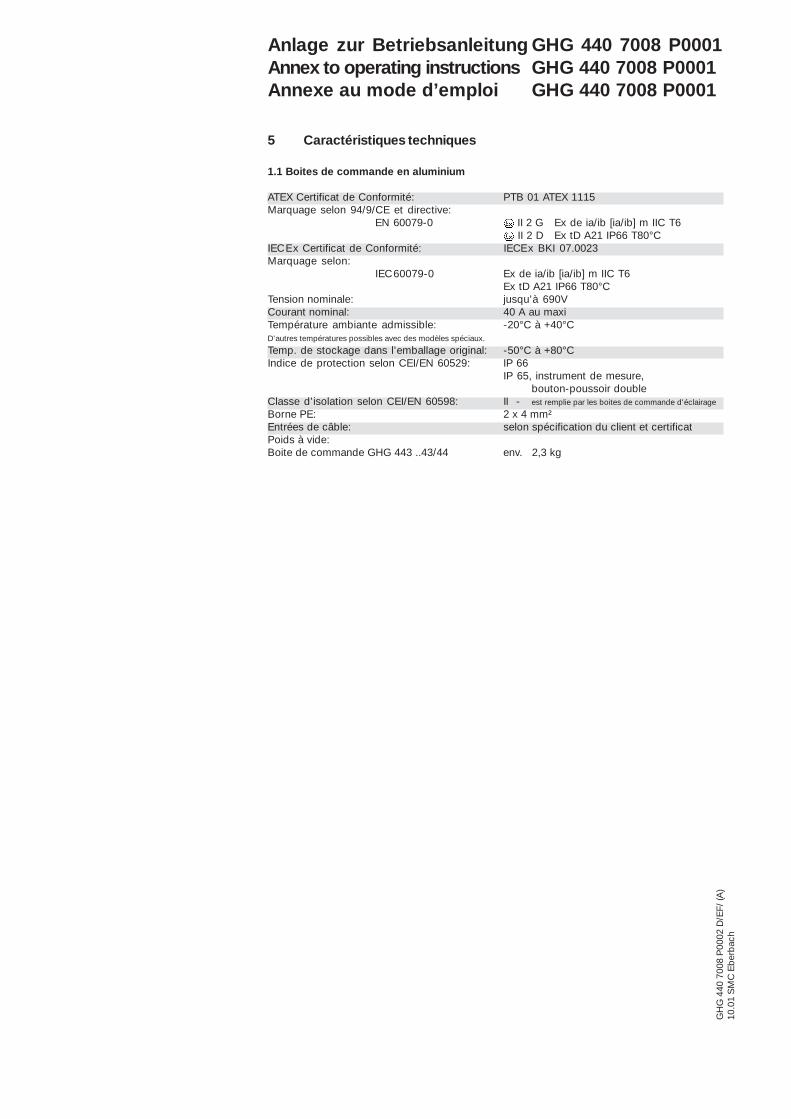
5 Caractéristiques techniques
1.1 Boites de commande en aluminium
ATEX Certificat de Conformité: PTB 01 ATEX 1115Marquage selon 94/9/CE et directive:
EN 60079-0 II 2 G Ex de ia/ib [ia/ib] m IIC T6 II 2 D Ex tD A21 IP66 T80°C
IECEx Certificat de Conformité: IECEx BKI 07.0023Marquage selon:
IEC60079-0 Ex de ia/ib [ia/ib] m IIC T6Ex tD A21 IP66 T80°C
Tension nominale: jusqu’à 690VCourant nominal: 40 A au maxiTempérature ambiante admissible: -20°C à +40°CD’autres températures possibles avec des modèles spéciaux.
Temp. de stockage dans l’emballage original: -50°C à +80°CIndice de protection selon CEI/EN 60529: IP 66
IP 65, instrument de mesure,bouton-poussoir double
Classe d’isolation selon CEI/EN 60598: II - est remplie par les boites de commande d'éclairage
Borne PE: 2 x 4 mm²Entrées de câble: selon spécification du client et certificatPoids à vide:Boite de commande GHG 443 ..43/44 env. 2,3 kg
Anlage zur Betriebsanleitung GHG 440 7008 P0001Annex to operating instructions GHG 440 7008 P0001Annexe au mode d’emploi GHG 440 7008 P0001

Explosion protected control units madeof plastic or stainless steel GHG 44.
Explosionsgeschützte Steuergeräte ausKunststoff oder Edelstahl GHG 44.
Boites de commande GHG 44. enplastique on en acier inoxydable pouratmosphères explosives
GHG 440 7008 P0001 D/E/F/ (L)
Betriebsanleitung
Operating instructions
Mode d’emploi
COOPER Crouse-Hinds GmbHCOOPER Crouse-Hinds GmbHCOOPER Crouse-Hinds GmbHCOOPER Crouse-Hinds GmbHCOOPER Crouse-Hinds GmbH
Neuer Weg - Nord 49D 69412 Eberbach / GermanyFone +49 (0) 6271/806 - 500Fax +49 (0) 6271/806 - 476Internet: http://www.CEAG.deE-Mail: [email protected]
GHG 448 25
GHG 448 35
���������� ��������������������� ����� ��� ����������������������������� �������������������������!��!����"#���$�%&'� �� ��������(�
)*���+��,� ������,������ �!�-�������!��%."��!�,��,�!�� �!�!��� ���)�!�������!��!����"#���$�%&'��� �!��/!�
%���%�����������!������!���������!������!��!�����������!��!����"#���$�%&'�������!�������������! ��������!��������������.���%�!�����
%0����0������������ ��������!��,������� 1����2���������!��,������ ������������������!��!����"#����$�%&'���������(�
345�����! �������6�6��6�7� �����667������� �������������%.���������6�����6�����!��!����"#���$�%&'�"������������
'8����������9�: �(����� ������������������������������� �����9�:��������� ������ ����� �������� ��������!��!����"#���$�%&'�
#���&����������;���<���������!���,��� ���������!��!����"#���$�%&'���, �������� ��������,���� �����,(�
4���0��������!������!���������������������!�� �����=��!����,���������������>%�!����������!�� ����!������ ��!�!���!�����������!��!����"#���$�%&'�
?���@���������������!�������9��� �!������A���,���������B�9�,�������!��������������,���������!��!����"#���$�%&'����� �B������ �������(
?C���@������������������!������� ����� ����� �!������!��������� ������B����,���������!�!����"#���$�%&'���!�� ����B�(�
+��A��,�������B�������"��D���E��"��,D�����������,� �����,�����!"!���!�����F������!��!�����#���$�%&'�EF������ ��(
5?���4���������������������� �!���,� ������,�B!������!�������������!��%."���D�!�����,� !��,��B���.D������!��!����"#���$�%&'�"� �!�,�D��!��,�,�
G���0��E�!�������!�����!���HI���������!�H1���������!�HI����!����!�����������.�I��%�!�����9�������������"�������������!��!�����������!��!����"#���$�%&'�
G?��5���������!����J��B� �,��D�����D������D�!�����!����D�����������<D�"�D�!�����D������D���E�!��������!"�!����"#���$�%&'��������!��(
0���%�7 �!�6�,�� ��������,�"��� ��7�����!������������%.�"���!K����� ��B� � �B��6�����E!K�%!������!��!����"#���$�%&'"�!��!�����
0*�������� ������B��� ��C��� ��C����!����������������������;�������������������!��!����"#���$�%&'� ��C������!����(�
0?L���5� ������������!�B�� �C������������� ����� � ����!���!�������������� ��������������!��!����"#���$�%&'� �C����!�� �(�

Cooper Crouse-Hinds GmbH22222
Inhalt:Inhalt:Inhalt:Inhalt:Inhalt:
Inhalt ...................................... 2Maßbild .................................. 3-5Anschlussbilder .................... 6-8
1 Technische Angaben ............ 31.1 Komplette Steuergeräte
Kunststoff .............................. 31.2 Komplette Steuergeräte
Edelstahl ................................ 31.3 Drucktaster + Schalter ......... 41.4 Signallampe ........................... 41.5 Potentiometer ........................ 41.6 Klemmenblock ....................... 41.7 Messinstrument .................... 51.8 Steuerschalter Ex 23 ............ 51.8.1 Steuerschalter Ex 28 ............ 51.9 Steuerschalter Ex 29 ............ 52 Sicherheitshinweise .............. 53 Normenkonformität ............... 64 Verwendungsbereich ............ 65 Verwendung/
Eigenschaften ........................ 6-76 Installation .............................. 76.1 Montage ................................ 76.2 Öffnen des Gerätes/
Elektrischer Anschluss ......... 7-86.3 Kabel- und Leitungs-
einführung; Verschluss-stopfen ................................... 8
6.4 Flansch-u. Metallplatten ........ 86.5 Schließen des Gerätes ......... 86.6 Inbetriebnahme ..................... 87 Instandhaltung / Wartung ..... 98 Reparatur / Instand-
setzung/ Änderungen ........... 99 Entsorgung / Wieder-
verwertung ............................ 9Verdrahtungstabelle .............. 24-25
10 Anzugsprüfdrehmomentefür Reihenklemmen ............... 26
11 PrüfdrehmomenteMetalleinführungen ................ 26-27
Konformitätserklärungseparat beigelegt
Contents:Contents:Contents:Contents:Contents:
Contents ................................ 2Dimensional drawings ........... 10-12Contact arrangement ............ 13-15
1 Technical Data ....................... 101.1 Control unit assemblies
plastic .................................... 101.2 Control unit assemblies
stainless steel ........................ 101.3 Push- button and switch ....... 111.4 Signal lamp ............................ 111.5 Potentiometer ........................ 111.6 Terminal block ....................... 111.7 Measuring instrument ........... 121.8 Control switch Ex 23 ............. 121.8.1 Control switch Ex 28 ............. 121.9 Control switch Ex 29 ............. 122 Safety instructions ................ 133 Conformity with standards ... 134 Field of application ................ 135 Application/ Properties ......... 13-146 Installation .............................. 146.1 Mounting ................................ 146.2 Opening the device /
Electrical connection ............. 14-156.3 Cable entry (KLE);
blanking plug ......................... 156.4 Flange and metal plates ........ 156.5 Closing the device ................ 156.6 Taking into operation ............. 157 Maintenance/Servicing ......... 168 Repairs/Modification ............ 169 Disposal/Recycling ............... 16
Wiring table ............................ 24-2510 Test torques
for terminal rows .................... 2611 Test torques
metal cable glands ................ 26-27
Declaration of conformity,enclosed separately.
Contenu:Contenu:Contenu:Contenu:Contenu:
Contenu ................................. 2Plans cotés ............................ 18-19Schéma desconnexions ............................ 20-21
1 Caractéristiquestechnique ............................... 17
1.1 Boites de commandecomplètes plastique ............. 17
1.2 Boites de commandecomplètes acier inoxydabl ... 17
1.3 Bouton-poussoir etinterrupteur ............................ 18
1.4 Lampe de signalisation ......... 181.5 Potentiomètre ........................ 181.6 Bornier ................................... 191.7 Instrument de mesure .......... 191.8 Commutateur de
commande Ex 23 .................. 191.8.1 Commutateur de
commande Ex 23 .................. 191.9 Commutateur de
commande Ex 29 .................. 192 Consignes de sécurité .......... 203 Conformité avec les
normes ................................... 204 Domaine d’utilisation ............. 205 Utilisation/Propriétés ............. 20-216 Installation .............................. 216.1 Montage ................................ 216.2 Ouverture de la boîte /
Raccordement électrique ..... 21-226.3 Entrées de câble (KLE)
bouchons de fermeture ........ 226.4 Plaques à brides ................... 226.5 Fermeture de la boîte /
Fermeture du couvercle ....... 226.6 Mise en service ..................... 227 Maintien/Entretien ................. 238 Réparation/Remise
en état .................................... 239 Évacuation des déchets/
Recyclage ............................. 23Table de câblage ................... 24-25
10 Couple de serrage testés ..... 2611 Couple de serrage testés
de connexion des bornes .... 26-27
Déclaration de conformité,jointe séparément.

Cooper Crouse-Hinds GmbH 33333
Explosionsgeschützte Steuergeräte aus Kunststoffoder Edelstahl GHG 44.
1 Technische Angaben
1.1 Komplette Kunststoffsteuergeräte
Gerätekennzeichnung nach 94/9/EG: II 2 G Ex d e ia/ib m [ia/ib] II C T4-T6 II 2 D Ex tD A21 IP66/IP65 T80°C, T95°C
EG-Baumusterprüfbescheinigung: PTB 99 ATEX 1044Bemessungsspannung: bis max.690 VBemessungsstrom: max 40 AZulässige Umgebungstemperatur: -20° C bis +40° C (Listenausführung)Abweichende Temperaturen sind bei Sonderversionen möglich)
Zul. Lagertemperatur in Originalverpackung: -50° C bis +80° CSchutzart nach EN/IEC 60529: IP 66 (Listenausführung)
IP 65 mit DoppeldrucktasterSchutzklasse nach EN/IEC 61140: I - wird von den Kunststoffsteuergeräten erfüllt.
II - mit MetallflanschPE - Anschlussklemmen: 2 x 4 mm²Anschlussklemmen: Anzahl - im Rahmen der BescheinigungLeitungseinführung: laut Auftrag, im Rahmen der BescheinigungLeergewicht:Steuergerät GHG 444 25 ca. 1,5 kgSteuergerät GHG 448 25 ca. 2,5 kgSteuergerät GHG 449 25 ca. 4,5 kgSteuergerät GHG 447 25 ca. 5,5 kgPrüfdrehmomente:Deckelschrauben / Anschlussklemmen 2,50 NmDruckschraube der KLE M12 1,65 NmDruckschraube der KLE M16 - M20 2,50 NmDruckschraube der KLE M25 3,50 NmDruckschraube der KLE M32 - M 63 5,00 Nm
1.2 Komplette Edelstahlsteuergeräte
Gerätekennzeichnung nach 94/9/EG: II 2 G Ex d e ia/ib m [ia/ib] II C T4-T6 II 2 D Ex tD A21 IP66/IP65 T80°C, T95°C
EG-Baumusterprüfbescheinigung: PTB 99 ATEX 1044Bemessungsspannung: bis 690 VBemessungsstrom: max. 40AZulässige Umgebungstemperatur: -20° C bis +40° C (Listenausführung)Abweichende Temperaturen sind bei Sonderversionen möglich)
Zul. Lagertemperatur in Originalverpackung: -50° C bis +80° CSchutzart nach EN/IEC 60529: IP 66 (Listenausführung)
IP 65 mit DoppeldrucktasterSchutzklasse nach EN/IEC 61140: II - wird von den Steuergeräten erfüllt.PE - Anschlussklemmen: 2 x 4mm²Anschlussklemmen: Anzahl - im Rahmen der BescheinigungLeitungseinführung: laut Auftrag, im Rahmen der BescheinigungLeergewicht:Steuergerät GHG 444 35 ca. 3,5 kgSteuergerät GHG 448 35 ca. 7,5 kgSteuergerät GHG 449 35 ca. 11,5 kgSteuergerät GHG 447 35 ca. 16,5 kgPrüfdrehmomente:Deckelschrauben / Anschlussklemmen 2,5 NmDruckschraube der Metall Ex- e KLE M16 7,5 Nm Typ E1WF/e, (Ex-e)Druckschraube der Metall Ex- e KLE M20 10,0 Nm Typ E1WF/e, (Ex-e)Druckschraube der Metall Ex- e KLE M25 15,0 Nm Typ E1WF/e, (Ex-e)Druckschraube der Metall Ex- e KLE M32 25,0 Nm Typ E1WF/e, (Ex-e)Druckschraube der Metall Ex- e KLE M40 30,0 Nm Typ E1WF/e, (Ex-e)Druckschraube der Metall Ex- e KLE M50 45,0 Nm Typ E1WF/e, (Ex-e)
Maßbilder Kunststoffsteuergeräte
GHG 444 2
GHG 448 2
GHG 449 2
GHG 447 2
X = BefestigungsmaßeX = BefestigungsmaßeX = BefestigungsmaßeX = BefestigungsmaßeX = Befestigungsmaße

Cooper Crouse-Hinds GmbH44444
Maßbilder Edelstahlsteuergeräte
GHG 444 3
GHG 448 3
GHG 449 3
GHG 447 3
Explosionsgeschützte Steuergeräte aus Kunststoffoder Edelstahl GHG 44.
1.3 Drucktastersockel 2 polig fürDrucktaster, Schlagtaster, Schalter und Schlüsseltaster
EG-Baumusterprüfbescheinigung: PTB 97 ATEX 1081 UNennspannung: bis max.500 V
Bemessungsstrom Bemessungsanschluss- Umgebungstemperaturmaximal querschnitt maximal
14 A 2,5 mm² 40 °C16 A 4,0 mm² starr 40 °C12 A 2,5 mm² 50 °C15 A 4,0 mm² starr 50 °C
Schaltvermögen AC 15: 250V / 6 A 500V / 4,0 ASchaltvermögen DC 13: 24V / 6 A 60V / 0,8 A 110V / 0,5 Amit Goldspitzkontakten: max. 400 mAAnschlussklemmen: 2 x 1,0 - 2,5 mm²; 1 x 4,0 mm² starrGewicht: ca. 0,15 kg
1.4 SignallampeEG-Baumusterprüfbescheinigung: PTB 98 ATEX 1040 UBemessungsspannung:
Ex ed IIC (LED) 20 V bis 250 V AC/DCEx ed IIC 12 V bis 24 V AC/DCEx d ia IIC 18 V bis 30 V DC
Bemessungsstrom:Ex ed IIC 20 V bis 250 V AC/DC (LED) 4 bis 15 mAEx ed IIC 12 V bis 24 V AC/DC max. 24 mAEx d ia IIC 18 V bis 30 V DC max. 25 mA
Anschlussklemme: 2 x 1,0 - 2,5 mm²Gewicht: ca. 0,15 kg
1.5 PotentiometerEG-Baumusterprüfbescheinigung: PTB 97 ATEX 1081 UBemessungsspannung: bis 250VLeistung: 1 WDrehbereich: 270°Skalierung: 0 - 100%Anschlussklemme: 2 x 2,5 mm² 2,5 NmGewicht: ca. 0,15 kg
1.6 KlemmenblockKonformitätsbescheinigung: PTB 99 ATEX 3132 UKlemmentyp: 6 x MXK 4Bemessungsspannung: bis 400VAnschlussquerschnitt: 2 x 0,2 - 4,0 mm²Gewicht: ca. 0,08 kg
X = Befestigungsmaße
1.3.1 Drucktastersockel 4 polig fürDrucktaster, Schlagtaster, Schalter und Schlüsseltaster
EG-Baumusterprüfbescheinigung: PTB 97 ATEX 1081 UBemessungsspannung: bis max.500 V
Bemessungsstrom Bemessungsanschluss- Umgebungstemperaturmaximal querschnitt maximal
14 A 2,5 mm² 40 °C16 A 4,0 mm² starr 40 °C12 A 2,5 mm² 50 °C15 A 4,0 mm² starr 50 °C
Schaltvermögen AC 15: 250V / 6 A 500V / 4,0 ASchaltvermögen DC 13: 24V / 6 A 60V / 0,8 A 110V / 0,5 Amit Goldspitzkontakten: max. 400 mAAnschlussklemmen: 2 x 2,5 mm²; 1 x 4,0 mm² starrPrüdrehmoment Anschlussklemmen 2,5 NmGewicht: ca. 0,17 kg

Cooper Crouse-Hinds GmbH 55555
2 Sicherheitshinweise
Die Steuergeräte GHG 44. aus Edelstahl oder Kunststoff
sind nicht für Zone 0 undZone 20 geeignet.Die auf den Steuergeräten angegebeneTemperaturklasse und Explosionsgruppeist zu beachten.Umbauten oder Veränderungen an den Steu-ergeräten sind nicht gestattet.Sie sind bestimmungsgemäß in unbeschä-digtem und einwandfreiem Zustand zu be-treiben.Als Ersatz und zur Reparatur dürfen nurOriginalteile von CEAG / Cooper Crouse-Hinds verwendet werden.Reparaturen, die den Explosionsschutz
Drucktaster Doppeldrucktaster
Maßangaben Vorsätze in mm
Schlagtaster NOT-AUS Schlagtaster
Schlagtaster NOT-AUS Schlüsseltaster mit Schlüssel
Messinstrument
Signalleuchte Steuerschalter
Steuerschalter Ex 23
Steuerschalter Ex 29
Explosionsgeschützte Steuergeräte ausKunststoffoder Edelstahl GHG 44.
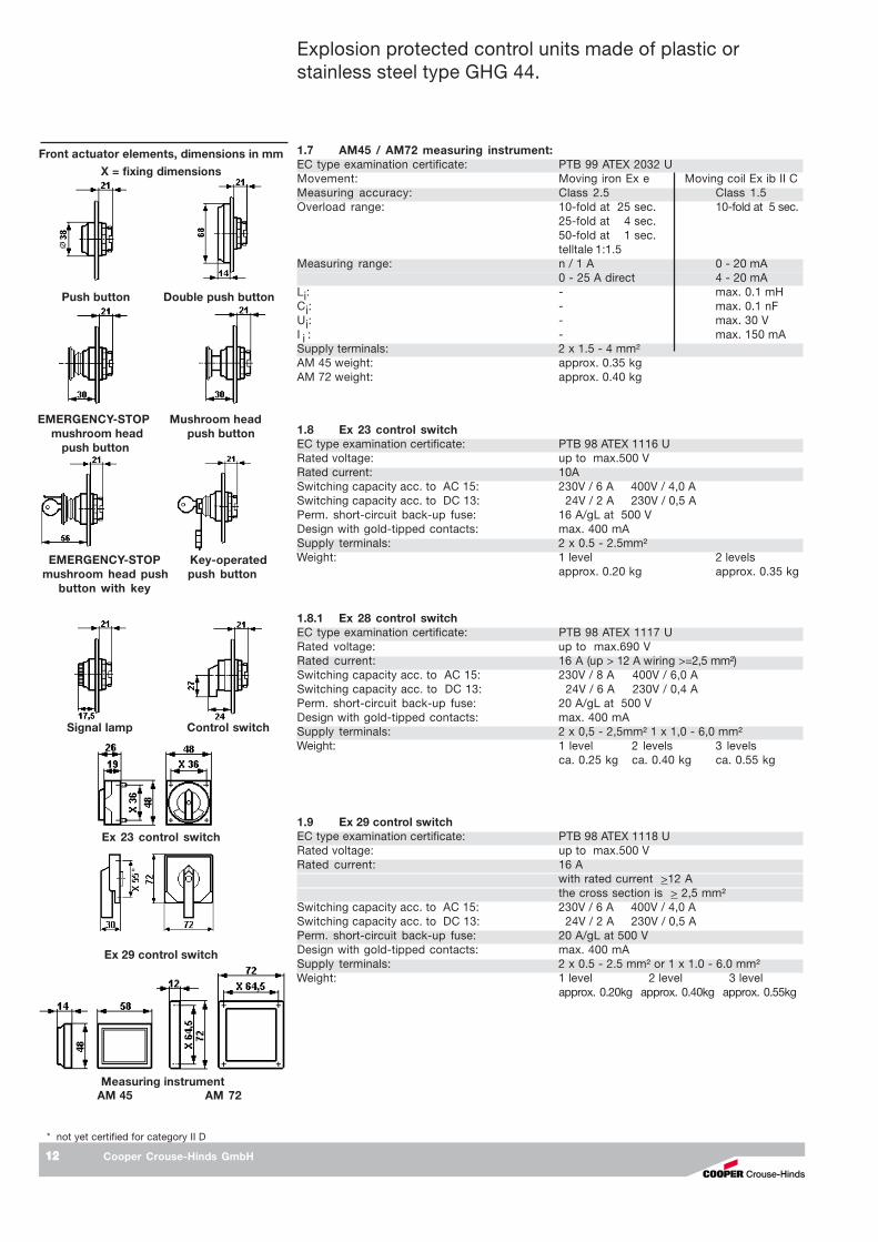
1.9 Steuerschalter Ex 29EG-Baumusterprüfbescheinigung: PTB 98 ATEX 1118 UBemessungsspannung: bis max.500 VMax. Bemessungsstrom: 16 A
Bei Nennstrom >12A ist der Querschnitt derAnschlussleitungen > 2,5mm² auszulegen
Schaltvermögen AC 15: 230V / 6 A 400V / 4,0 ASchaltvermögen DC 13: 24V / 2 A 230V / 0,5 AZul. Kurzschlussvorsicherung: 20 A/gL bei 500 VAusführung mit Goldspitzkontakten: max. 400 mAAnschlussklemmen: 2 x 0,5 - 2,5mm² oder 1 x 1,0 - 6,0mm²Gewicht: 1 Etage 2 Etagen 3 Etagen
ca. 0,25 kg ca. 0,40 kg ca. 0,55 kg
AM 45 AM 72
X = Befestigungsmaße
* z.Zt. nicht bescheinigt für Kategorie II D
1.7 Messinstrument AM45 /AM72EG-Baumusterprüfbescheinigung: PTB 99 ATEX 2032 UMesswerk: Dreheisen Ex -e Drehspule Ex ib IIGenauigkeit: Klasse 2,5 Klasse 1,5Überlastbereich: 10-fach - 25 sek. 10-fach - 5 sek.
25-fach - 4 sek.50-fach - 1 sekanzeigend 1:1,5
Messbereiche: n / 1A 0 - 20 mA0 - 25 A direkt 4 - 20 mA
Li: - max. 0,1 mHCi: - max. 0,1 nFUi: - max. 30 VI i : - max. 150 mAAnschlussklemme: 2 x 1,5 - 4 mm²Gewicht, AM 45: 0,35 kgGewicht, AM 72: 0,40 kg
1.8 Steuerschalter Ex 23EG-Baumusterprüfbescheinigung: PTB 98 ATEX 1116 UBemessungsspannung: bis max.500 VMax. Bemessungsstrom: 10 ASchaltvermögen AC 15: 230V / 6 A 400V / 4,0 ASchaltvermögen DC 13: 24V / 2 A 230V / 0,5 AZul. Kurzschlussvorsicherung: 16A/gL bei 500VAusführung mit Goldspitzkontakten: max. 400 mAAnschlussklemmen: 2 x 0,5 - 2,5mm²Gewicht: 1 Etage 2 Etagen
ca. 0,20 kg ca. 0,35 kg
betreffen, dürfen nur von CEAG / CooperCrouse-Hinds oder einer qualifiziertenElektrofachkraft in Übereinstimmung mitnational geltenden Regeln durchgeführtwerden.Vor Inbetriebnahme müssen die Steuerge-räte entsprechend der im Abschnitt 6 ge-nannten Anweisung geprüft werden.
Die Anforderungen der EN 61241-0 und -1,u.a. in Bezug auf übermäßige Staubab-lagerungen und Temperatur, sind vomAnwender zu beachten.
Beachten Sie die nationalen Sicherheits-und Unfallverhütungsvorschriften und dienachfolgenden Sicherheitshinweise in die-ser Betriebsanleitung, die wie dieser Textin Kursivschrift gefasst sind!
1.8.1 Steuerschalter Ex 28EG-Baumusterprüfbescheinigung: PTB 98 ATEX 1117 UBemessungsspannung: bis max.690 VMax. Bemessungsstrom: 16 A (ab > 12 A Anschlussleitung >=2,5 mm²)Schaltvermögen AC 15: 230V / 8 A 400V / 6,0 ASchaltvermögen DC 13: 24V / 6 A 230V / 0,4 AZul. Kurzschlussvorsicherung: 20A/gL bei 500VAusführung mit Goldspitzkontakten: max. 400 mAAnschlussklemmen: 2 x 0,5 - 2,5mm² 1 x 1,0 - 6,0 mm²Gewicht: 1 Etage 2 Etagen 3 Etagen
ca. 0,25 kg ca. 0,40 kg ca. 0,55 kg

Cooper Crouse-Hinds GmbH66666
Explosionsgeschützte Steuergeräte aus Kunststoffoder Edelstahl GHG 44.
21
22 44
43
R1
34
3311
12
44
43
R2
34
33
24
23
14
13
21
22
R3
11
12
41
42
31
32
44
43
R4
34
33
24
2311
12
21
22
R5
11
12
31
32 44
43
S 1
S 2S 4
S 3
S 2S 4
S 3
S2 S3S1
S4
S4
Drucktastersockel 2 x 2 polig
Drucktastersockel 1 x 4 polig
S 1
21
22 44
43
R1
34
3311
12
44
43
R2
34
33
24
23
14
13
21
22
R3
11
12
41
42
31
32
44
43
R4
34
33
24
2311
12
21
22
R5
11
12
31
32 44
43
S2 S3S1
Schlagtaster mit verstärkter VerrastungGHG 410 1437R....
SchlagscheibeROT
Einlegeplättchenschwarz
Unterteilgelb
5 Verwendung / Eigenschaften Eigenschaften Eigenschaften Eigenschaften Eigenschaften
Die Steuergeräte GHG 44. aus Kunststoff oderEdelstahl dienen zur Vor-Ort-Steuerungelektrischer Anlagen in explosionsgefährdetenBereichen. Diese Geräte sind, abhängig vomEinzelfall, je nach Bedarf mit den verschiede-nen Einbaukomponenten ausgerüstet.
Die Steuergeräte können optional mit Anreih-klemmen bis 2,5 mm² unter dem Einbauklapp-gerüst ausgestattet und komplett für denkundenseitigen Anschluss verdrahtet sein.Speziell gekennzeichnete Sonderausführun-gen der Steuergeräte können in "eigen-sicheren Stromkreisen" eingesetzt werden.Die für die "Eigensicherheit" maßgebendenelektrischen Grenzwerte sind zu beachten.
Die Angaben der elektrischen Kontakt-bestückung befinden sich auf denKomponentensockeln. Die Ausführung mitGoldkontakten ist mit "G" gekennzeichnet(max. Strombelastung siehe "TechnischeDaten").
Um eine sichere Trennung zu gewährleisten, sinddie Öffnerkontakte als Zwangsöffner ausgeführt.Die Sockel sind je nach Bedarf auch mit0,6 W Widerständen, Feinsicherungen undDioden bestückt (max. Verlustleistung 1W).
Die Messinstrumente AM 72 und AM 45dienen zur Vor-Ort-Anzeige von elektrischenGrößen. (Ausführung des Messwerkes, derGenauigkeit sowie Anschlussversion - siehe"Technische Daten").
Die Kleinsteuerschalter können durch Aus-schneiden des Schaltkragens an der jeweili-gen Abschließposition über ein Vorhänge-schloss abgeschlossen werden ( ∅ Schloß-bügel bis 5 mm). Steuerschaltervorsätze Ex23sind am Schaltkragen an der entsprechendenAbschließposition mit einer Bohrung ∅ 5,5mmzu versehen und somit über oben genanntesVorhängeschloss abschließbar.
Der 4 polige Drucktastersockel benötigt indiesen Gehäusen zwei Einbaufelder einesnormalen Drucktastersockels.Der Bedienvorsätzen liegt dann in der Mitteder beiden Einbaufelder.
Der 4 polige Drucktastersockel kann mit denStandart CCH Bedienvorsätzen betriebenwerden.Soll der 4 polige Drucktastersockel mit einemSchlagtaster Not-AUS Vorsatz mit Verrastungbetrieben werden, so muss dieser Vorsatzmit einer verstärkten Verrastung ausgestattetsein. Dieser Vorsatz ist an der roten Schlag-scheibe mit schwarzen Einlegeplättchenerkennbar und z. B. unter der CCH Artikel-nummer GHG 410 143737373737R.... erhältlich.
3 Normenkonformität
Die Geräte sind von Cooper Crouse-Hinds(nachfolgend mit CCHCCHCCHCCHCCH abgekürzt) gemäßDIN EN ISO 9001 entwickelt, gefertigt undgeprüft worden.
Die Geräte entsprechen den aufgeführtenNormen, in der separat beigelegtenKonformitätserklärung.
94/9 EWG: Geräte und Schutzsysteme zurbestimmungsgemäßen Verwendung inexplosionsgefährdeten Bereichen. WeitereAnforderungen wie die EG Richtlinie Elektro-magnetische Verträglichkeit (2004/108/EG)werden von den Steuergeräten erfüllt.
4 Verwendungsbereich
Die Kunststoff- oder Edelstahlsteuergeräte mitden Einbaukomponenten (siehe "TechnischeDaten"), sind zum Einsatz in explosions-gefährdeten Bereichen der Zonen 1, 2 undZone 21, 22 gemäß EN 60079-10-1 und -2geeignet!
Die eingesetzten Gehäusematerialien ein-schließlich der außenliegenden Metallteilebestehen aus hochwertigen Werkstoffen, dieeinen anwendungsgerechten Korrosionsschutzund Chemikalienresistenz in "normalerIndustrieatmosphäre" gewährleisten:
- glasfaserverstärktes Polyester- schlagfestes Polyamid- Edelstahl AISI 316 L
Bei einem Einsatz in extrem aggressiverAtmosphäre, können Sie zusätzliche Informa-tionen über die Chemikalienbeständigkeit dereingesetzten Materialien, bei Ihrer zuständi-gen Cooper Crouse-Hinds Niederlassungerfragen.

Cooper Crouse-Hinds GmbH 77777
Anschlussbilder SchaltungSteuerschalter Ex 23/Ex 28/Ex 29
6011
6019
6060
6062
6065
6033
6170
. 021
. 023
. 024
. 061
. 063
. 066
. 067
2
1
Bild 1
6 Installation
Für das Errichten / Betreiben sind die relevan-ten nationalen Vorschriften (z.B. Betr.Si.V,Gerätesicherheitsgesetz in Deutschland) sowiedie allgemein anerkannten Regeln der Technikmaßgebend.
6.16.16.16.16.1 Montage / DemontageMontage / DemontageMontage / DemontageMontage / DemontageMontage / Demontage
Die Montage der Kunststoff- oder Edelstahl-steuergeräte kann ohne Öffnen der Gehäuseerfolgen.
Die Steuergeräte dürfen bei der Direktmontagean der Wand nur an den vorgesehenenBefestigungspunkten eben aufliegen. Diegewählte Schraube muss der Befestigungs-öffnung angepasst sein (siehe Maßbilder Seite3 + 4 sowie Bild 2 + 3, Seite 8).
Sie dürfen die Öffnung nicht beschädigen (z.B.Verwendung einer Unterlegscheibe).
Bei übermäßigem Anziehen können dieKunststoffsteuergeräte beschädigt werden.
Die Kunststoffsteuergeräte GHG 444 2,GHG 448 2, GHG 449 2 und GHG 447 2 sindzur Befestigung auf den CEAG - Geräte-haltern mittels Form- oder selbstschneidendenSchrauben geeignet (siehe Bild 4 - 8, Seite 9).
Die betreffende Montageanleitung ist zubeachten.
Die Montage der Wandbefestigungslaschenan den Edelstahlsteuergeräten GHG 444 3,GHG 448 3, GHG 449 3 und GHG 447 3erfolgt, wie in Bild 2 + 3 Seite 8 dargestelt.
Auf die Mindestanzahl der Laschen achten!
Explosionsgeschützte Steuergeräte aus Kunststoffoder Edelstahl GHG 44.
6.2 Öffnen des Gerätes/Elektrischer Anschluss
Der elektrische Anschluss des Betriebsmittelsdarf nur durch Fachpersonal erfolgen.Das Schaltbild der Einbaukomponenten ist aufden Komponenten angegeben, dem Schalt-gerät beigelegt oder aus der Betriebsanleitungzu entnehmen.Bei verdrahteten Steuergeräten ist der demGerät beigelegte Anschlussplan zu beachten.
!!!!! Die maximale Anzahl der verwendetenLeiter und internen Verbindungsleiterkann aus den Verdrahtungstabellen abSeite 24 entnommen werden.
Nach dem Ausklappen des Klappgerüsteszur leichteren Einführung der Kabel undLeitungen bzw. zum Verdrahten auf die unterdem Klappgerüst eingebauten Anreihklem-men muss das Klappgerüst wieder ord-nungsgemäß befestigt werden.
Werden die Einbaukomponenten (MessinstrumentAM 72 und AM 45, Drucktastersockel,Signalleuchtensockel, Steuerschaltersockel,Potentiometersockel usw.) zur leichterenVerdrahtung aus der Hutprofilschiene des inden Steuergeräten montierten Klappgerüstesausgeschnappt, sind die Komponentenhiernach wieder vorschriftsmäßig in dieentsprechende Einrastposition auf derHutprofilschiene des Klappgerüstes einzuset-zen.Zum Ausschnappen der Komponenten (u.a.auch die Messinstrumente AM72 + AM45),werden die Rasthaken zum entriegeln nachaußen gezogen.
Achtung: Die Einrastpositionen der Einbau-komponenten müssen mit den Einkerbun-gen der Hutprofilschiene übereinstimmen !
Zur Aufrechterhaltung der Zündschutzart istder Leiteranschluss mit besonderer Sorgfaltdurchzuführen.
Die Isolation muss bis an die Klemmeheranreichen. Der Leiter selbst darf nichtbeschädigt sein.
Die minimal und maximal anschließbarenLeiterquerschnitte sind zu beachten (siehetechnische Daten).Alle Schrauben und / oder Muttern derAnschlussklemmen, auch die der nichtbenutzten, sind fest anzuziehen.Die optional eingebauten Standardklemmensind zum Direktanschluss von Leitern mitKupferadern ausgelegt.
Ein Schalten an der Achse der Steuer-schaltersockel Ex 23 und Ex 29 beigeöffnetem Gehäuse ist nicht zulässig(um die Schalter wieder korrekt schließenzu können).
Schaltwerk
4 5 6
Sonder- schaltwerk
7 8 9
Die Steuerschalter Ex 29 sind optional mit einermontierten Abschließvorrichtung versehen undebenso mit einem Vorhängeschloss abschließbar.
Angaben aus Punkt 3 und 4 sind bei derVerwendung zu berücksichtigen.Andere als die beschriebenen Anwendun-gen sind ohne schriftliche Erklärung derFa. CEAG / Cooper Crouse-Hinds nichtzulässig.Beim Betrieb sind die in der Betriebsanlei-tung unter Punkt 7 genannten Anweisun-gen zu beachten.

Cooper Crouse-Hinds GmbH88888
Anschlußbilder SchaltungSteuerschalter Ex 23/Ex 28/Ex 29
. 049
. 037
. 191
6.3 Kabel-und Leitungs-einführungen (KLE);Verschlussstopfen
Es dürfen generell nur bescheinigte KLE´sund Verschlussstopfen verwendet werden.Für bewegliche Leitungen sind Trompeten-verschraubungen oder andere geeigneteEinführungen mit zusätzlicher Zug-entlastung zu verwenden.
Beim Einsatz von KLE mit einer niedrigeren alsder für das Gerät zutreffenden IP-Schutzart(siehe Seite 3) wird die IP-Schutzart desgesamten Gerätes reduziert.
Die für die eingesetzten KLE maßgebendenMontagerichtlinien sind zu beachten.
Nicht benutzte Einführungsöffnungen sind miteinem bescheinigten Verschlussstopfen zuverschließen, um die Mindestschutzartherzustellen.Es ist darauf zu achten, daß bei der Installati-on der KLE´s die für den Leitungsdurchmessergeeigneten Dichtungseinsätze verwendetwerden. Bei ausschneidbaren Dichtungs-einsätzen ist sicherzustellen,daß der Einsatzordnungsgemäß dem Leitungsdurchmesserangepasst wird.Zur Sicherstellung der erforderlichen Mindest-schutzart sind die KLE´s fest anzuziehen.
Bei übermäßigem Anziehen kann dieSchutzart beeinträchtigt werden.
Achtung: Beim Anziehen der Hutmutter derMetall - KLE (Typ ADE) ist die Verschrau-bung mit einem geeigneten Werkzeuggegen Verdrehen zu sichern.
Alle nicht benutzten metrischen CEAG /Cooper Crouse-Hinds KLE sind mit dembescheinigten Verschluss für metrische KLEzu verschließen.
Explosionsgeschützte Steuergeräte aus Kunststoffoder Edelstahl GHG 44.
Schraube M6 x 16 Wandbefestigungs- Federring lasche
Bild 2 Wandbefestigungslasche
Montage rechts
Montage unten
Bild 3 Montage der Wand-befestigungslasche
6.4 Kunststoff*-, Metallflanscheund Metallplatten
Müssen Flanschplatten demontiert werden(z.B. zum Bohren von Einführungsöffnungen),ist bei der Montage zur Aufrechterhaltung derMindestschutzart auf den korrekten Sitz derFlanschplatte und den Sitz des Befestigungs-bügels zu achten.Die Flanschplatten der Edelstahlklemmenkästensind so zu montieren, daß die IP-Schutzart gewähr-leistet bleibt. Dabei ist auf den exakten Sitz desDichtungselementes zu achten.
Von aussen herangeführte PE-Leitungensind auf die dafür vorgesehene PE-Klemmeam Flansch anzuschließen. Der maximaleAnschlussquerschnitt beträgt 50 mm²Achtung: Metallflansche, Metallplatten undMetallverschraubungen müssen in denPotentialausgleich miteinbezogen werden.* z.Zt. nicht bescheinigt für Kategorie II D
6.5 Schließen des Gerätes /Deckelverschluss
Beim Aufsetzen der Gehäusedeckel istdarauf zu achten, daß die Vorsätze korrektmit den Einbaukomponenten übereinstim-men und der zum Gehäuseunterteilgehörige Deckel verwendet wird.
Die Schaltgriffe der Steuerschalter Ex 23 undEx 29 müssen in der Stellung stehen, die siebeim Öffnen des Steuergerätes innehatten.Beim Aufsetzen des Deckels ist darauf zu ach-ten, daß die Achse der Steuerschalter Ex 23 undEx 29 in die Mitnehmeröffnung des Schaltgriffeseingreift.Alle Fremdkörper sind aus dem Gerät zu ent-fernen.Zur Sicherstellung der erforderlichen Mindest-schutzart sind die Deckelschrauben fest anzu-ziehen.
Bei übermäßigem Anziehen kann dieSchutzart beeinträchtigt werden.
6.6 InbetriebnahmeVor Inbetriebnahme des Betriebsmittels sind die inden einzelnen nationalen Bestimmungen genann-ten Prüfungen durchzuführen. Ausserdem ist vorder Inbetriebnahme die korrekte Funktion und In-stallation des Betriebsmittels und der Einbau-komponenten (Messinstrument, Signalleuchte, Tas-ter usw.) in Übereinstimmung mit dieser Betriebs-anleitung und anderen anwendbaren Bestimmun-gen zu überprüfen.Die Nullpunkteinstellung des Messinstrumentezeigersist vor der Inbetriebnahme zu überprüfen.Gegebenenfalls mit der Justierschraube denMessgerätezeiger auf den Nullpunkt einjustieren.
Unsachgemäße Installation und Betrieb derSteuergeräte kann zum Verlust der Garantieführen.
Schaltwerk
4 5 6
Sonder- schaltwerk
7 8 9
Bei Messinstrumenten für Wandleranschlussn/1A (Bild1 , Pos 2, Seite 6) können über eineoben am Messinstrument angebrachteKlappe die Wechselskalen (Bild 1, Pos 1,Seite 6) ausgetauscht werden.
Die Errichtungshinweise für eigensichereelektrische Betriebsmittel sind zu beachten.Es ist sicherzustellen, daß die für denspeziellen, eigensicheren Stromkreiszulässige äussere Kapazität und Induktivitätnicht überschritten wird.
Wird das Betriebsmittel in der Ausführung"Schutzisoliert" ausgeführt, kann dasentsprechendeKlebeschild ( ) GHG 905 1002 P0005beim Hersteller angefordert werden.Wird die eingebaute Klemmentragschienenicht komplett mit Reihenklemmen bestückt,muss die Klemmentragschiene in denPotentialausgleich mit einbezogen werden.

Cooper Crouse-Hinds GmbH 99999
Explosionsgeschützte Steuergeräte aus Kunststoffoder Edelstahl GHG 44.
Gerätehalter Größe 3 fürRohrbefestigung,horizontal
Gerätehalter Größe 3 für Gitterrinnen- undWandbefestigung, horizontal
Befestigungslöcher für KunststoffSteuergerät GHG 444 25
E
Bild 7 Gerätehalter Größe 3 für Gitter-rinnen- undWand-befestigung,vertikal
Bild 6 Gerätehalter Größe 3 für Rohr-befestigung,vertikal
Befestigungs-löcher fürKunststoffSteuergerätGHG 444 2
C
B
Bild 8 2 x Gerätehalter Größe 3 für Rohrbefestigung, horizontal
A = Befestigungslöcher für:Kunststoffsteuergerät GHG 448 27 (Maß X = 0 mm)Kunststoffsteuergerät GHG 449 27 nur vertikal (Maß X = 267mm)Kunststoffsteuergerät GHG 447 27 nur vertikal (Maß X = 540mm)
A
Reparaturen, die den Explosionsschutzbetreffen, dürfen nur von CEAG / CooperCrouse-Hinds oder einer qualifiziertenElektrofachkraft in Übereinstimmung mitnational geltenden Regeln durchgeführtwerden (z.B. EN 60079-19).
Umbauten oder Änderungen am Betriebsmittelsind nicht gestattet; ausgenommen ist dasAnbringen von zusätzlichen KLE´s und dasMontieren von Anschlussklemmen im Rahmender Zulassung des Betriebsmittels oder nachAngaben des Herstellers.
Bei Austausch einzelner Einbaukomponenten(Messinstrument, Taster usw.) ist Pkt. 6.2"Öffnen des Gerätes /Elektrischer Anschluss"zu beachten.
9 Entsorgung /Wiederverwertung
Bei der Entsorgung des Betriebsmittels undder Einbaukomponenten (Meßinstrument,Signalleuchte, Taster usw.) sind die jeweilsgeltenden nationalen Abfallbeseitigungsvor-schriften zu beachten.
Zur Erleichterung der Wiederverwertbarkeitvon Einzelteilen sind Kunststoffteile mit demKennzeichen des verwendeten Kunststoffesversehen.
Programmänderungen und -ergänzungen sindvorbehalten.
88888 Reparatur / Instandsetzung /Reparatur / Instandsetzung /Reparatur / Instandsetzung /Reparatur / Instandsetzung /Reparatur / Instandsetzung /ÄnderungÄnderungÄnderungÄnderungÄnderung
Instandsetzungsarbeiten / Reparaturen dürfennur mit CEAG / Cooper Crouse-HindsOriginalersatzteilen vorgenommen werden.Bei Schäden an der druckfesten Kapselung istnur ein Austausch zulässig. Im Zweifelsfalle istdas betroffene Betriebsmittel an CEAG /Cooper Crouse-Hinds zur Reparaturzurückzugeben.
7 Instandhaltung / Wartung
Die für die Wartung / Instandhaltung vonelektrischen Betriebsmitteln in explosions-gefährdeten Bereichen geltenden nationa-len Bestimmungen sind einzuhalten(z.B. EN 60079-17).
Vor Öffnen des Gehäuses Spannungs-freiheit sicherstellen bzw. geeigneteSchutzmaßnahmen ergreifen.
Bei eigensicheren Stromkreisen ist dasArbeiten unter Spannung zulässig.
Die erforderlichen Wartungsintervalle sindanwendungsspezifisch und daher in Abhän-gigkeit von den Einsatzbedingungen vomBetreiber festzulegen.Im Rahmen der Wartung sind vor allem dieTeile, von denen die Zündschutzart abhängt,zu prüfen (z.B. Unversehrtheit der druckfestenKomponenten, des Gehäuses, der Dichtungenund der Kabel- und Leitungseinführungen),sowie die Schaltwerksfunktion.Sollte bei einer Wartung festgestellt werden,daß Instandsetzungsarbeiten erforderlich sind,ist Abschnitt 8 dieser Betriebsanleitung zubeachten.
Bild 4
ABefestigungslöcher für Kunststoff
Steuergerät GHG 444 2
Bild 5
Befestigungs-löcher fürKunststoffSteuergerätGHG 444 2

Cooper Crouse-Hinds GmbH1010101010
Explosion protected control units made of plastic orstainless steel type GHG 44.
1 Technical data
1.1 Control unit assemblies, plastic
Marking acc. to 94/9/EC: II 2 G Ex d e ia/ib m [ia/ib] II C T4-T6 II 2 D Ex tD A21 IP66/IP65 T80°C, T95°C
EC type examination certificate: PTB 99 ATEX 1044Rated voltage: up to 690 VRated current: max. 40 APermissible ambient temperature: -20° C to +40° C (catalogue version)Deviating temperatures possible with special versions.
Perm.storage temperature in original packing: -50° C to +80° CProtection category acc. to EN/IEC 60529: IP 66 (catalogue version)
IP 65 with double push buttonInsulation class acc. to EN/IEC 61140: I - plastic terminal boxes fulfil this requirement
II - with metal flangePE- terminal: 2 x 4 mm²Terminals: acc. to customer´s specification and as certifiedCable entries: acc. to customer´s specification and as certifiedWeight when empty: (catalogue version)GHG 444 25 control unit approx 1.5 kgGHG 448 25 control unit approx 2.5 kgGHG 449 25 control unit approx 4.5 kgGHG 447 25 control unit approx 5.5 kgTest torques:Cover screws/ Terminal cross-section 2.50 NmCap nut of the plastic cable entry M12 1.65 NmCap nut of the plastic cable entry M16 - M20 2.50 NmCap nut of the plastic cable entry M25 3.50 NmCap nut of the plastic cable entry M32 - M 63 5.00 Nm
1.2 Control unit assemblies, stainless steel
Marking acc. to 94/9/EC: II 2 G Ex d e ia/ib m [ia/ib] II C T4-T6 II 2 D Ex tD A21 IP66/IP65 T80°C, T95°C
EC type examination certificate: PTB 99 ATEX 1044Rated voltage: up to 690 VRated current: max. 40 APermissible ambient temperature: -20° C to +40° C (catalogue version)Deviating temperatures possible with special versions.
Perm.storage temperature in original packing: -50° C to +80° CProtection category acc. to EN/IEC60529: IP 66 (catalogue version)
IP 65 with double push buttonInsulation class acc. to EN/IEC 61140: II - metal terminal boxes fulfil this requirementPE- terminal: 2 x 4 mm²Terminals: acc. to customer´s specification and as certifiedCable entries: acc. to customer´s specification and as certifiedWeight when empty: (catalogue version)GHG 444 35 control unit approx. 3.5 kgGHG 448 35 control unit approx. 7.5 kgGHG 449 35 control unit approx. 11.5 kgGHG 447 35 control unit approx. 16.5 kgTest torques:Cover screws/ Terminal cross-section 2.5 NmCap nut of the Ex-e metal cable entry M16 7.5 Nm type, E1WF/e (Ex-e)Cap nut of the Ex-e metal cable entry M20 10.0 Nm type, E1WF/e (Ex-e)Cap nut of the Ex-e metal cable entry M25 15.0 Nm type, E1WF/e (Ex-e)Cap nut of the Ex-e metal cable entry M32 25.0 Nm type, E1WF/e (Ex-e)Cap nut of the Ex-e metal cable entry M40 30.0 Nm type, E1WF/e (Ex-e)Cap nut of the Ex-e metal cable entry M50 45.0 Nm type, E1WF/e (Ex-e)
Dimensions control units, plastic
GHG 444 2
GHG 448 2
GHG 449 2
GHG 447 2
X = Fixing dimensions

Cooper Crouse-Hinds GmbH 1111111111
Explosion protected control units made of plastic orstainless steel type GHG 44.
1.3 Actuator 2 pole forpush button, Mushroom head p.b., switch and Key-operated pushbutton
EC type examination certificate: PTB 97 ATEX 1081 URated voltage: up to max.500 V
rated current rated supply terminal Permissible ambientmax. temperature max.14 A 2,5 mm² 40 °C16 A 4,0 mm² single wire 40 °C12 A 2,5 mm² 50 °C15 A 4,0 mm² single wire 50 °C
Switching capacity acc. to AC 15: 250V / 6 A 500V / 4,0 ASwitching capacity acc. to DC 13: 24V / 6 A 60V / 0,8 A 110V / 0,5 Awith gold-tipped contacts: max. 400 mASupply terminal: 2 x 1.0 - 2.5mm²; 1 x 4,0 mm² single wireWeight: approx. 0.15 kg
1.4 Signal lampEC type examination certificate: PTB 98 ATEX 1040 URated voltage
Ex ed IIC (LED) 20 V to 250 V AC/DCEx ed IIC 12 V to 24 V AC/DCEx d ia IIC 18 V to 30 V DC
Rated current:Ex ed IIC 20 V to 250 V AC/DC (LED) 4 to 15 mAEx ed IIC 12 V to 24 V AC/DC max. 24 mAEx d ia IIC 18 V to 30 V DC max. 25 mA
Supply terminal: 2 x 1.0 - 2.5 mm²Weight: approx. 0.15 kg
1.5 PotentiometerEC type examination certificate: PTB 97 ATEX 1081 URated voltage: up to 250VRating: 1 WTurning range: 270°Scale: 0 - 100%Supply terminal: 2 x 1.0 - 2.5 mm²Weight: approx. 0.15 kg
1.6 Terminal blockCertificate of conformity: PTB 99 ATEX 3132 UType of terminal: 6 x MXK 4Rated voltage: up to 400VConductor cross-section: 2 x 0.2 - 4.0 mm²Weight: approx. 0.08 kg
Dimensions control units stainless steel
GHG 444 3
GHG 448 3
GHG 449 3
GHG 447 3
X = Fixing dimensions
1.3.1 Actuator 4 pole forpush button, Mushroom head p.b., switch and Key-operated pushbutton
EC type examination certificate: PTB 97 ATEX 1081 URated voltage: to max.500 V
rated current rated supply terminal Permissible ambientmax. temperature max.14 A 2,5 mm² 40 °C16 A 4,0 mm² single wire 40 °C12 A 2,5 mm² 50 °C15 A 4,0 mm² single wire 50 °C
Switching capacity acc. to AC 15: 250V / 6 A 500V / 4,0 ASwitching capacity acc. to DC 13: 24V / 6 A 60V / 0,8 A 110V / 0,5 Awith gold-tipped contacts: max. 400 mASupply terminal: 2 x 1,0 - 2,5 mm²; 1 x 4,0 mm² single wireTest torques: 2,5 NmWeight: approx 0,17 kg
Cooper Crouse-Hinds GmbH1212121212
Explosion protected control units made of plastic orstainless steel type GHG 44.
Front actuator elements, dimensions in mm
Push button Double push button
EMERGENCY-STOP Mushroom head mushroom head push button push button
EMERGENCY-STOP Key-operated mushroom head push push button
button with key
Measuring instrument
Signal lamp Control switch
Ex 23 control switch
Ex 29 control switch
AM 45 AM 72
X = fixing dimensions
1.9 Ex 29 control switchEC type examination certificate: PTB 98 ATEX 1118 URated voltage: up to max.500 VRated current: 16 A
with rated current >12 Athe cross section is > 2,5 mm²
Switching capacity acc. to AC 15: 230V / 6 A 400V / 4,0 ASwitching capacity acc. to DC 13: 24V / 2 A 230V / 0,5 APerm. short-circuit back-up fuse: 20 A/gL at 500 VDesign with gold-tipped contacts: max. 400 mASupply terminals: 2 x 0.5 - 2.5 mm² or 1 x 1.0 - 6.0 mm²Weight: 1 level 2 level 3 level
approx. 0.20kg approx. 0.40kg approx. 0.55kg
* not yet certified for category II D
1.7 AM45 / AM72 measuring instrument:EC type examination certificate: PTB 99 ATEX 2032 UMovement: Moving iron Ex e Moving coil Ex ib II CMeasuring accuracy: Class 2.5 Class 1.5Overload range: 10-fold at 25 sec. 10-fold at 5 sec.
25-fold at 4 sec.50-fold at 1 sec.telltale 1:1.5
Measuring range: n / 1 A 0 - 20 mA0 - 25 A direct 4 - 20 mA
Li: - max. 0.1 mHCi: - max. 0.1 nFUi: - max. 30 VI i : - max. 150 mASupply terminals: 2 x 1.5 - 4 mm²AM 45 weight: approx. 0.35 kgAM 72 weight: approx. 0.40 kg
1.8 Ex 23 control switchEC type examination certificate: PTB 98 ATEX 1116 URated voltage: up to max.500 VRated current: 10ASwitching capacity acc. to AC 15: 230V / 6 A 400V / 4,0 ASwitching capacity acc. to DC 13: 24V / 2 A 230V / 0,5 APerm. short-circuit back-up fuse: 16 A/gL at 500 VDesign with gold-tipped contacts: max. 400 mASupply terminals: 2 x 0.5 - 2.5mm²Weight: 1 level 2 levels
approx. 0.20 kg approx. 0.35 kg
1.8.1 Ex 28 control switchEC type examination certificate: PTB 98 ATEX 1117 URated voltage: up to max.690 VRated current: 16 A (up > 12 A wiring >=2,5 mm²)Switching capacity acc. to AC 15: 230V / 8 A 400V / 6,0 ASwitching capacity acc. to DC 13: 24V / 6 A 230V / 0,4 APerm. short-circuit back-up fuse: 20 A/gL at 500 VDesign with gold-tipped contacts: max. 400 mASupply terminals: 2 x 0,5 - 2,5mm² 1 x 1,0 - 6,0 mm²Weight: 1 level 2 levels 3 levels
ca. 0.25 kg ca. 0.40 kg ca. 0.55 kg

Cooper Crouse-Hinds GmbH 1313131313
Explosion protected control units made of plastic orstainless steel type GHG 44.
Contact arrangement CircuitryEx 23/ Ex 28/ EX 29 control switch
Code
6011
6019
6060
6062
6065
6033
6170
. 021
. 023
. 024
. 061
. 063
. 066
. 067
2
1
Fig. 1
Switch mechanism
4 5 6
Special switch mechanism
7 8 9
22222 Safety instructionsSafety instructionsSafety instructionsSafety instructionsSafety instructions
The plastic or stainless steelcontrol units GHG 44. are not
suitable for zone 0 and zone 20hazardous areas.
The temperature class and explosiongroup marked on the control units shallbe observed.
Modifications to the control units orchanges of their design are not permitted.They shall be used for their intendedpurpose and in perfect and cleancondition.
For replacement and repair only genuineCEAG / Cooper Crouse-Hinds spare partsshall be used.
Repairs that affect the explosionprotection, may only be carried out byCEAG / Cooper Crouse-Hinds or aqualified electrician in compliance withthe respective national regulations.
Prior to their taking into operation, thecontrol units will have to be checked inaccordance with the instructions as persection 6.
The requirements of the EN 61241-0 and -1regarding excessive dust deposits andtemperature to be considered from theuser.
Observe the national safety rules andregulations for prevention ofaccidents as well as the safety instructionsincluded in these operating instructions setin italics the same as this text!
33333 Conformity with standardsConformity with standardsConformity with standardsConformity with standardsConformity with standardsThe control units have been designed,manufactured and tested by Cooper Crouse-Hinds (CCH), according to the state of the artand to DIN EN ISO 9001.
The contro is conform to the standardsspecified in the EC-Declaration of conformity,enclosed separately.
94/9 EC: Equipment and protective systemsintended for use in potentially explosive
atmospheres.
The control units fulfil further requirementssuch as those of the ECdirective onelectromagnetic compatibility (2004/108/EEC).
44444 Field of applicationField of applicationField of applicationField of applicationField of application
The plastic or stainless steel control unitsGHG 44. are suitable for use in zone 1, 2 and21, 22 hazardous areas acc. toIEC 60079-10-1 and -2.
The enclosure materials employed, includingthe exterior metal parts, are made of high-quality materials which ensure a corrosionprotection and resistance to chemicalsubstances corresponding to the requirementsin a “normal industrial atmosphere”:
- glass-fibre reinforced polyester- impact resistant polyamide- special steel AISI 316 L
In case of use in an extremely aggresiveatmosphere, please refer to manufacturer
55555 Application / PropertiesApplication / PropertiesApplication / PropertiesApplication / PropertiesApplication / Properties
The plastic or stainless steel control unitsGHG 44. are designed for the control in situ ofelectrical installations in explosiveatmospheres. The devices are individuallyfitted with built-in components that meet theirspecific application.
The control units can, at option, be deliveredfitted with series terminals up to 2,5mm²under the hinged framework and wired readyfor connection by the customer.
Adequately marked special versions of thecontrol units can be operated in „intrinsicallysafe circuits“. The electric limiting valuesapplicable to „intrinsic safety“ shall beobserved.
The respective details on the equipment withelectrical contacts are given on thecomponent bases.
The version fitted with gold-tipped contacts ismarked with a „G“ (for max. current load seeTechnical data).
In order to achieve a reliable isolation, thenormally closed contacts are designed asforced break contacts. Where required, thebases are fitted with 0.6 W resistors, fine-wirefuses and diodes (max. dissipated energy 1 W).
The measuring instrument serves for theindication in situ of electrical values. For thetype of measuring mechanism, accuracy andconnected version, see „Technical data“).
When the switching collar on small controlswitches is cut out at the respective lockingposition, they can be padlocked (lockingshackle Ø up to 5 mm).Ex 23 control switch actuator elements shallbe provided with a drilled hole of 5.5 mm Ø atthe respective locking position on theirswitching collar and can thus be padlockedas described before.

Cooper Crouse-Hinds GmbH1414141414
21
22 44
43
R1
34
3311
12
44
43
R2
34
33
24
23
14
13
21
22
R3
11
12
41
42
31
32
44
43
R4
34
33
24
2311
12
21
22
R5
11
12
31
32 44
43
S 1
S 2S 4
S 3
S 2S 4
S 3
S2 S3S1
S4
S4
Actuator 2 x 2 pole
Actuator 1 x 4 pole
S 1
21
22 44
43
R1
34
3311
12
44
43
R2
34
33
24
23
14
13
21
22
R3
11
12
41
42
31
32
44
43
R4
34
33
24
2311
12
21
22
R5
11
12
31
32 44
43
S2 S3S1
thrust washerred
inserting signblack
baseyellow
Mushroom-head pushbutton actuator"EMERGENCY STOP"
GHG 410 1437R....
6.1 Mounting
The plastic and stainless steel control unitscan be mounted without opening theirenclosure.When being mounted directly onto the wall,the control units shall rest evenly only at thefastening points provided for them. Thechosen screw shall match the fastening hole(see dimensional drawing, page 10 + 11 andFig. 2, page 15).
They shall not damage the hole (e.g. use of awasher).
If the screws are overtightened, the plasticcontrol units may be damaged.
The plastic control units GHG 444 2, 448 2,449 2 and GHG 447 2. are suitable forfastening onto CEAG / Cooper Crouse-Hindsapparatus holders by means of self-cuttingscrews (see fig. 4-8, page 16).
The respective mounting instructions will haveto be observed.
Mounting the wall mounting brackets onto thestainless steel control units GHG 444 3, 448 3,449 3 and GHG 447 3 is done as per fig. 2 + 3in page 15.
Observe the min. No. of wall mountingbrackets!
6.26.26.26.26.2 Opening the device/Opening the device/Opening the device/Opening the device/Opening the device/Electrical connectionElectrical connectionElectrical connectionElectrical connectionElectrical connection
The electrical connection of the apparatus mayonly be carried out by skilled staff. The circuitdiagram of the built-in components is eithershown on these components or attached tothem or shown in the operating instructions. Asto wired control units, the circuit diagramattached to the device is to be observed.
After the hinged framework has been foldedout in order to facilitate the introduction ofcables or the connection to the terminalsarranged under the hinged framework, it shallagain be fitted properly in place.
If, for the sake of an easier wiring, the built-incomponents (AM 72 and AM 45 measuringinstrument, push-button base, signal lampbase, control switch base, potentiometer baseetc.) are snapped off the top hat rail fitted inthe hinged framework, the components will,thereafter, have to be properly re-inserted inthe lock-in position on the top hat rail of thehinged framework.
! ! ! ! ! The total number of used conductors andinternal wiring conductors, can be found outin the wiring table page 24.
In order to snap off the components(including measuring instruments AM 72 andAM 45), the snap-in hooks are unlocked bypulling them outwards.
Mind: The lock-in positions of the built-incomponents shall match the notches onthe top hat rail!
In order to maintain the explosion category,the conductors will have to be connected withspecial care.
The insulation shall reach up to the terminal.The conductor itself must not be damaged.
The connectible min. and max. conductorcross-sections will have to be observed (seetechnical data).All screws and/or nuts of the supply terminals,also of those remaining vacant, shall betightened down.
The fitted optional standard terminals aredesigned for direct connection of conductorswith copper cores.
Switching on the axis of the Ex 23 andEx 29 control switch base whilst theenclosure is open, is not permitted (inorder to be able to properly close theswitch again).
On measuring instruments for c.t. connection n/1A (fig. 1, item 2, page 13) the interchangeablescales can be changed via a flap arranged onthe upper part of the measuring instrument (fig. 1,item 1, page 13).
6 Installation
For the mounting and operation, therespective national regulations (e. g. Betr.Si.V,equipment safety act) as well as the generalrules of engineering will have to be observed.
At option, the Ex 29 control switches areprovided with a fitted locking device so thatthey can also be padlocked.
The 4 pole pushbutton contact can be addedwith the standard CCH actuators. If the 4pole pushbutton contact is added with anEmergency STOP Mushroom-headpushbutton actuator, then you have to usethe actuators with CCH order numberGHG 410 143737373737R.....This actuators can be recognize by the redthrust washer and black inserting sign.
The data as per point 3 and 4 will have tobe taken into account with the use.Applications other than described are notpermitted without CEAG / Cooper Crouse-Hinds’s prior written consent.For the operation, the instructions statedin section 7 of the operating instructionswill have to be observed.
Explosion protected control units made of plastic orstainless steel type GHG 44.

Cooper Crouse-Hinds GmbH 1515151515
Explosion protected control units made of plastic orstainless steel type GHG 44.
6.5 Closing the device /Cover closure
When placing the enclosure cover care hasto be taken that the front actuator elementsexactly correspond to the built-incomponents and that the cover pertainingto the bottom part of the enclosure is used.
The switching handles of the Ex 23 and Ex 29control switches shall have the same positionas they had when the apparatus was opened.
When putting on the cover care has to betaken that the axis of the Ex 23 and Ex 29control switches engages in the driving hole ofthe switching handle.
Any foreign matter shall be removed from theapparatus.
In order to ensure the required minimumprotection category, the cover screws are tobe tightened down.
Overtightening might impair the protectioncategory.
6.6 Taking into operation
Prior to taking the apparatus into operation,the tests specified in the relevant nationalregulations will have to be carried out. Apartfrom that, the correct functioning andinstallation of the apparatus in accordancewith these operating instructions and otherapplicable regulations will have to bechecked.
Prior to taking into operation, the zero pointadjustment of the measuring instrument indexhas to be checked. Where necessary, themeasuring instrument index is to be adjustedto the zero point by means of the adjustingscrew.
Incorrect installation and use of the controlunits can invalidate the guarantee.
Contact arrangement CircuitryEx 23/Ex 28/EX 29 control switch
Code
. 049
. 037
. 191
Screw M6 x 16 Wall mounting Lock washer bracket
Fig. 2 Wall mounting bracket
Mounting at right side
Mounting at bottom
Fig. 3 Mounting the wallmounting bracket
Switch mechanism
4 5 6
Special switch mechanism
7 8 9
6.36.36.36.36.3 Cable entries (KLE);Cable entries (KLE);Cable entries (KLE);Cable entries (KLE);Cable entries (KLE);blanking plugsblanking plugsblanking plugsblanking plugsblanking plugs
Generally, only certified cable entries andblanking plugs may be used. Flexiblecables shall be used with trumpet-shapedcable glands or other suitable entries withadditional pull-relief.
When using cable entries with a lower IPprotection than that which applies to thedevice (see page 11), the IP protection of thewhole device will be reduced.The mounting directives applicable to thecable entries fitted shall be observed.
In order to establish the minimum protectioncategory, unused holes shall be closed with acertified blanking plug.Care has to be taken that when fitting thecable entries, sealing inserts appropriate tothe cable diameter be used.In case of sealing inserts that are cut out, itwill have to be ensured that the insert isproperly adapted to the cable diameter.In order to ensure the required minimumprotection category, the cable entries will haveto be tightened down.
Overtightening might impair the protectioncategory.Attention: When tightening the cap nut ofthe type ADE metal cable entry, thescrewing is to be protected againsttwisting by means of a suitable tool.
All vacant metric CEAG / Cooper Crouse-Hinds cable entries shall be closed with thecertified blanking plug for metric cable entries.
6.4 Flange and metal plates
If flange plates have to be removed in case ofplastic terminal boxes (e.g. for drilling entryholes), attention will have to be paid to theproper fit of the flange plate and of the clampclip when mounting them in order to maintainthe minimum protection category.
The instructions for the installation of intrinsicallysafe electrical apparatus are to be observed.It has to be ensured that the externalcapacitance and inductance permitted for thespecific intrinsically safe circuit are not exceeded.
In the case of building up the electrical
equipment in the "protective insulation"version, appropriate sticker( ) GHG 905 1002 P0005 can berequested by the manufacturer.
If the inserted terminal rail is not equipped
completely with line-up terminals, the terminalrail must be included in the equipotentialearth connection also.
Flange plates for stainless steel terminal boxesshall be fitted so that the IP protection inmaintained. Pay attention to the proper seat ofthe sealing element.
PE conductors fed from outside are to beconnected to the PE terminal provided onthe flange. The maximum cross-section is50mm².Attention: Metal flanges, metal plates andmetal cable glands shall be included in theequipotential earth connection.

Cooper Crouse-Hinds GmbH1616161616
Fig. 6 Apparatusholder size 3for pipemounting,vertically
Explosion protected control units made of plastic orstainless steel type GHG 44.
Fig. 8 2 x Apparatus holder size 3 for pipe mounting, horizontally
A = Fastening holes for:control unit GHG 448 27 (Dimensions X = 0 mm)control unit GHG 449 27 only vertically (Dimensions X = 267mm)control unit GHG 447 27 only vertically (Dimensions X = 540mm)
A
7 Maintenance / Servicing
The relevant national regulations whichapply to the maintenance/repair ofelectrical apparatus in explosiveatmospheres, will have to be observed(EN 60079-17).
Before opening the enclosure make surethat the terminal box is disconnected fromthe voltage, or take the appropriateprotective measures.
In case of intrinsically safe circuits, working ispermitted while voltage applies.
The required maintenance intervals depend onthe respective application and will thereforehave to be determined by the user dependenton the conditions of use.
When servicing the apparatus, particularlythose parts that are decisive for the type ofprotection against explosion, will have to bechecked (e. g. intactness of flameproofenclosed components, enclosure, cableglands, efficacy of the cover gaskets) and thefunctioning of the switch mechanism.
If during servicing repairs prove to benecessary, section 8 of these operatinginstructions will have to be observed.
8 Repairs / Overhaul /ModificationModificationModificationModificationModification
Repairs may only be carried out with genuineCEAG / Cooper Crouse-Hinds spare parts.In case of a damaged flameproof enclosure,only its replacement is permitted. In case ofdoubt, the respective apparatus will have tobe returned for repair to CEAG / CooperCrouse-Hinds.
Repairs that affect the explosionprotection, may only be carried out byCEAG / Cooper Crouse-Hinds or aqualified electrician in compliance withthe applicable national rules(EN 60079-19).
Modifications to the apparatus or changes ofits design are not permitted, except for themounting of additional cable entries and theinstallation of supply terminals in accordancewith the approval of the apparatus or acc. toinstructions of the manufacturer.
When replacing individual components(measuring instrument, push-button etc.),para. 6.2 „Opening the device/Electricalconnection“ is to be observed.
9 Disposal / Recycling
When the apparatus is disposed of, therespective national regulations on wastedisposal will have to be observed.
In order to facilitate the recycling of individualcomponents, plastic parts have been providedwith the identification mark of the plasticmaterial used.
Subject to modifications or supplement of theproduct range.
Apparatus holder size 3 for pipe mounting,horizontally
Apparatus holder size 3 for channel andwall mounting, horizontally
Fastening holes for control unitGHG 444 25
E
Fig. 7 Apparatusholder forchannel andwall mounting,vertically
Fasteningholes forcontrol unitGHG 444 25
Fasteningholes forcontrol unitGHG 444 25
C
B
Fig. 4
AFastening holes for control unit
GHG 444 25
Fig 5

Cooper Crouse-Hinds GmbH 1717171717
Boites de commande GHG 44. en plastique on en acierinoxydable pour atmosphères explosives
1 Caractéristiques techniques
1.1 Boites de commande en plastique
Marquage selon 94/9/CE et directive: II 2 G Ex d e ia/ib m [ia/ib] II C T4-T6 II 2 D Ex tD A21 IP66/IP65 T80°C, T95°C
Attestation d’examen CE de type: PTB 99 ATEX 1044Tension nominale: jusqu’à 690VCourant nominal: 40 A au maxiTempérature ambiante admissible: -20°C à +40°C (modèles de liste)D’autres températures possibles avec des modèles spéciaux.
Temp. de stockage dans l’emballage original: -50°C à +80°CIndice de protection selon EN/CEI 60529: IP 66 (modèles de liste)
IP 65 bouton-poussoir doubleClasse d’isolation selon EN/CEI 61140: I - est remplie par les boites de bornes d'éclairage
II - avec plaque métalique
Borne PE: 2 x 4 mm²Bornes de connexion: selon spécification du client et certificatEntrées de câble: selon spécification du client et certificatPoids à vide: (modèles de liste)Boite de commande GHG 444 25 env. 1,5 kgBoite de commande GHG 448 25 env. 2,5 kgBoite de commande GHG 449 25 env. 4,5 kgBoite de commande GHG 447 25 env. 5,5 kgCouples de serrage testés:Vis du couvercle / Borne de raccordement 2,50 NmEcrou borgne bas de l’entrée plastique M12 1,65 NmEcrou borgne bas de l’entrée plastique M16-M20 2,50 NmEcrou borgne bas de l’entrée plastique M25 3,50 NmEcrou borgne bas de l’entrée plastique M32-M50 5,00 Nm
1.2 Boites de commande en acier inoxydable
Marquage selon 94/9/CE et directive: II 2 G Ex d e ia/ib m [ia/ib] II C T4-T6 II 2 D Ex tD A21 IP66/IP65 T80°C, T95°C
Attestation d’examen CE de type: PTB 99 ATEX 1044Tension nominale: jusqu’à 690VCourant nominal: 40 A au maxiTempérature ambiante admissible: -20°C à +40°C (modèles de liste)D’autres températures possibles avec des modèles spéciaux.
Temp. de stockage dans l’emballage original: -50°C à +80°CIndice de protection selon EN/CEI 60529: IP 66,(modèles de liste)
IP 65,bouton-poussoir doubleClasse d’isolation selon EN/CEI 61140: II - est remplie par les boites de bornes d'éclairage métalique
Borne PE: 2 x 4 mm²Bornes: selon spécification du client et certificatEntrées de câble: selon spécification du client et certificatPoids à vide: (modèles de liste)Boite de commande GHG 444 35 env. 3,5 kgBoite de commande GHG 448 35 env. 7,5 kgBoite de commande GHG 449 35 env. 11,5 kgBoite de commande GHG 447 35 env. 16,5 kgCouples de serrage testés:Vis du couvercle / Borne de raccordement 2,5 NmEcrou borgne bas de l’entrée métallique M 16 7,5 Nm type, E1WF/e (Ex-e)Ecrou borgne bas de l’entrée métallique M 20 10,0 Nm type, E1WF/e (Ex-e)Ecrou borgne bas de l’entrée métallique M 25 15,0 Nm type, E1WF/e (Ex-e)Ecrou borgne bas de l’entrée métallique M 32 25,0 Nm type, E1WF/e (Ex-e)Ecrou borgne bas de l’entrée métallique M 40 30,0 Nm type, E1WF/e (Ex-e)Ecrou borgne bas de l’entrée métallique M 50 45,0 Nm type, E1WF/e (Ex-e)
Dimensions boites de commandeen plastique
GHG 444 2
GHG 448 2
GHG 449 2
GHG 447 2
X = dimensions de fixation

Cooper Crouse-Hinds GmbH1818181818
Boites de commande GHG 44. en plastique on en acierinoxydable pour atmosphères explosives
1.3 Bouton-poussoir 2 pole et interrupteurAttestation d’examen CE de type: PTB 97 ATEX 1081 UTension nominale: jusqu’à 500 V
Courant nominal Borne de connexion Température ambiantemaxi admissible maxi14 A 2,5 mm² 40 °C16 A 4,0 mm² rigide 40 °C12 A 2,5 mm² 50 °C15 A 4,0 mm² rigide 50 °C
Puissance de coupure AC15: 250V / 6 A 500V / 4,0 APuissance de coupure DC 13: 24V / 6 A 60V / 0,8 A 110V / 0,5 AModèle à pointes de contact d’or: 400 mA au maxiBorne de connexion: 2 x 1,0 - 2,5mm²; 1 x 4,0 mm²Poids: env. 0,15 kg
1.4 Lampe de signalisationAttestation d’examen CE de type: PTB 98 ATEX 1040 UTension nominale:
Ex ed IIC (LED) 20 V - 250 V AC/DCEx ed IIC 12 V - 24 V AC/DCEx d ia IIC 18 V - 30 V DC
Courant nominale:Ex ed IIC 20 V - 250 V AC/DC (LED) 4 - 15 mAEx ed IIC 12 V - 24 V AC/DC max. 24 mAEx d ia IIC 18 V - 30 V DC max. 25 mA
Borne de raccordement: 2 x 1,0 - 2,5 mm²Poids: env. 0,15 kg
1.5 PotentiomètreAttestation d’examen CE de type: PTB 97 ATEX 1081 UTension nominale: jusqu’à 250 VPuissance: 1 WDomaine de rotation: 270°Echelle: 0 - 100%Borne de raccordement: 2 x 1,0 - 2,5 mm²Poids: env. 0,15 kg
Dimensions boites de commande enacier inoxydable
GHG 444 3
GHG 448 3
GHG 449 3
GHG 447 3
X = dimensions de fixation
1.3.1 Bouton-poussoir 4 pole et interrupteurAttestation d’examen CE de type: PTB 97 ATEX 1081 UTension nominale: jusqu’à. 500 V
Courant nominal Borne de connexion Température ambiantemaxi admissible maxi14 A 2,5 mm² 40 °C16 A 4,0 mm² rigide 40 °C12 A 2,5 mm² 50 °C15 A 4,0 mm² rigide 50 °C
Schaltvermögen AC 15: 250V / 6 A 500V / 4,0 ASchaltvermögen DC 13: 24V / 6 A 60V / 0,8 A 110V / 0,5 Amit Goldspitzkontakten: max. 400 mAAnschlussklemmen: 2 x 1,0 - 2,5 mm²; 1 x 4,0 mm²Prüdrehmoment Anschlussklemmen 2,5 NmGewicht: ca. 0,17 kg

Cooper Crouse-Hinds GmbH 1919191919
Boites de commande GHG 44. en plastique on en acierinoxydable pour atmosphères explosives
Dimensions des têtes de commande en mm
Bouton-poussoir Bouton-poussoirdouble
Bouton-poussoir Bouton-poussoir à frapper à frapper SECOURS-STOP
Bouton-poussoir à frapper Bouton- SECOURS-STOP poussoir avec clé à clé amovible
Instrument de mesure
Lampe de signalisation Commutateur de commande
Commutateur de commande Ex 23
Commutateur de commande Ex 29
AM 45 AM 72
X = dimensions de fixation
1.9 Commutateur de commande Ex 29Attestation d’examen CE de type: PTB 98 ATEX 1118 UTension nominale: jusqu’à 500 VCourant nominal: 16A
A un courant nominal supérieur à 12A -section transversale > 2,5mm²
Puissance de coupure AC 15: 230V / 6 A 400V / 4,0 APuissance de coupure DC 13: 24V / 2 A 230V / 0,5 AFusible de court-circuit adm. placé en amont: 20A/gL à 500VModèle à pointes de contact d’or: 400 mA au maxiBornes de raccordement: 2 x 0,5 - 2,5 mm² ou en 1 x 1,0 - 6 mm²Poids: 1 étage 2 étages 3 étages
env. 0,20kg env. 0,40kg env. 0,55kg
* pour le moment, pas encore certifié Catégorie II D
1.6 BornierCertificat de conformité: PTB 99 ATEX 3132 UType de borne: 6 x MXK 4Tension nominale: jusqu’à 400 VSection transversale du conducteur: 2 x 0,2 - 4,0 mm²Poids: env. 0,08 kg
1.7 Instrument de mesure AM45 / AM72Attestation d’examen CE de type: PTB 99 ATEX 2032 U Ex ib II CMécanisme de mesure: ferromagnétique magnéto-électrique
Ex e Ex ib II CJustesse: Classe 2,5 Classe 1,5Gamme de surcharge: 10 fois à 25 sec. 10 fois à 5 sec.
25 fois à 4 sec.50 fois à 1 sec.lecture 1:1,5
Etendue de mesure: n / 1A 0 - 20 mA0 - 25 A directe 4 - 20 mA
Li: - 0,1 mH au maxiCi: - 0,1 nF au maxiUi: - 30 V au maxiI i : - 150 mA au maxiBorne de raccordement: 2 x 1.5 - 4 mm²Poids AM 45 env. 0,35 kgPoids AM 72 env. 0,40 kg
1.8 Commutateur de commande Ex 23Attestation d’examen CE de type: PTB 98 ATEX 1116 UTension nominale: jusqu’à 500VCourant nominal maximum: 10APuissance de coupure AC 15: 230V / 6 A 400V / 4,0 APuissance de coupure DC 13: 24V / 2 A 230V / 0,5 AFusible de court-circuit adm. placé en amont: 16A/gL à 500VModèle à pointes de contact d’or: 400 mA au maxiBorne de raccordement: 2 x 0,5 - 2,5mm²Poids: 1 étage 2 étages
env. 0,20 kg env. 0,35 kg
1.8.1 Commutateur de commande Ex 28Attestation d’examen CE de type: PTB 98 ATEX 1117 UTension nominale: jusqu’à 690VCourant nominal maximum: 16A ( > 12 A -> >=2,5 mm²)Puissance de coupure AC 15: 230V / 8 A 400V / 6,0 APuissance de coupure DC 13: 24V / 6 A 230V / 0,4 AFusible de court-circuit adm. placé en amont: 20A/gL à 500VModèle à pointes de contact d’or: 400 mA au maxiBorne de raccordement: 2 x 0,5 - 2,5mm² 1 x 1,0 - 6,0 mm²Poids: 1 étage 2 étages 3 étages
ca. 0.25 kg ca. 0.40 kg ca. 0.55 kg

Cooper Crouse-Hinds GmbH2020202020
Boites de commande GHG 44. en plastique on en acierinoxydable pour atmosphères explosives
Schémas des connexions CouplageCommutateur decommande Ex 23 / Ex 28 / Ex 29
6011
6019
6060
6062
6065
6033
6170
. 021
. 023
. 024
. 061
. 063
. 066
. 067
2
1
Fig. 1
Mécanisme decommutation
4 5 6 Mécanisme de
commutation spécial
7 8 9
4 Domaine d’utilisationLes boites de commande conviennent àl’emploi en les zones 1, 2 et 21, 22 d’uneatmosphère explosive selonCEI 60079-10-1 et -2!
Pour l’enveloppe, y compris les piècesmétalliques extérieures, des matières dequalité supérieure ont été employées quiassurent une protection appropriée contre lacorrosion et une résistance contre des agentschimiques en “atmosphère industriellenormale”:
- polyester chargé verre- polyamide anti-choc- acier spécial AISI 316 L
En cas d‘utilisation en atmosphèreextrèmement corrosive, vous pouvez obtenirdes informations complémentaires sur larésistance chimique des matériel utilisés chezla succursale Cooper Crouse-Hinds de votrerégion.
5 Utilisation / PropriétésLes boites de commande en plastique on enacier inoxydable GHG 44. servent à lacommande sur place d’installationsélectriques en atmosphère explosive.Dépendant de l’emploi spécifique et suivantle cas, les appareils sont dotés descomposants encastrés appropriés.
Au choix, les boites de commande peuventou être équipées des bornes jusqu’à 2,5mm² au-dessous du cadre d’encastrementou être complètement câblees pour leraccordement par le client.
Des exécutions spéciales de la boite decommande avec repère appropriée peuventêtre exploitées dans des „circuits à sécuritéintrinsèque“.Les valeurs limites valables pour la „sécuritéintrinsèque“ doivent être respectées.
L’équipement en contacts électriques setrouve sur les socles de composants. L’exé-cution à pointes de contact d’or porte larepère "G" (intensité max. admissible selonles caractéristiques techniques).
Afin d’obten une déconnexion fiable, descontacts de rupture forcée ont été montéscomme contacts normaux.Suivant le cas, les socles sont aussi dotés desrésistances de 0,6 W, des fusibles pour faibleintensité et des diodes (puissance dissipée de 1W au maxi).L’instrument de mesure AM 72 et AM 45 sert àl’indication sur place des grandeurs électriques.Le type du mécanisme de mesure, la justesse etle type de raccordement sont indiqués dans lescaractéristiques techniques.
Si le collet de commutation des manipulateurs estdécoupé à la position de verrouillage respective,il est possible de les cadenasser dans cetteposition (Ø de l’étrier jusqu’à 5 mm).
3 Conformité avec les normes
Les boites de commande, fabriquées etcontrôlées par Cooper Crouse-Hinds(abrégé ci-dessous par CCHCCHCCHCCHCCH) conformémentà DIN EN ISO 9001.
Les boites de commande sont conformesaux normes reprises dans la déclaration deconformité, jointe séparément.
94/9 CE: Appareils et systèmes deprotection destinés à être utilisés enatmosphère explosible.
De plus, les boites de commande répondent àd’autres exigences comme par exemple, cellesde la directive CE “Compatibilitéélectromagnétique” (2004/108/CEE).
2 Consignes de sécurité
Les boites de commande enplastique on en acier inoxydable
neconviennent pas à l’emploien zone 0 et zone 20.
Le groupe d’explosion et la classe detempérature marqués sur les appareilsdevront être respectés.
Il n’est pas permis de transformer ou demodifier les boites de commande.
Seuls des boites de commande intactes etparfaites devront être employées pour lafonction qui leur est dévolue.
Seules des pièces de rechangehomologuées d’origine CEAG / CooperCrouse-Hinds devront être utiliséescomme remplacement et pour desréparations.
Des réparations qui portent sur laprotection contre l’explosion, ne devrontêtre exécutées que par CEAG / CooperCrouse-Hinds ou par un électricienqualifié en conformité avec larèglementation nationale en vigueur.
Avant la mise en service, les boites decommande doivent être vérifiées selonl’instruction donnée dans la section 6.
Les exigences des EN 61241-0 et -1 en cequi concerne des dépôts de poussièredémesurés et une température doiventêtre considérées par I’utilisateur.
Respectez les prescriptions nationales desécurité et de prévoyance contre lesaccidents ainsi que les consignes desécurité qui suivent dans ce mode d’emploiet qui sont mises en italique comme ce texte!

Cooper Crouse-Hinds GmbH 2121212121
66666 InstallationInstallationInstallationInstallationInstallationPour l’installation et l’exploitation de cesappareils, la règlementation nationale envigueur ainsi que les règles de la techniquegénéralement reconnues devront êtrerespectées.
6.16.16.16.16.1 MontageMontageMontageMontageMontageLe montage des boites de commande enplastique on en acier inoxydable peut se fairesans ouvrir l’enveloppe.En cas de montage directement au mur, lesboites de commande ne doivent reposer auniveau du mur que dans les points de fixationprévus. La vis choisie doit être en rapportavec le trou de fixation (voir plan coté, page17-18 et fig. 2+3, page 22) et elle ne doit pasavarier le trou (par ex. emploi d’une rondelle).
Si les vis sont forcées, l’appareil en plastiquepeut être avarié.
Les boites de commande en plastiqueGHG 444 2, GHG 448 2, GHG 449 2 et GHG447 2 peuvent être montées sur des porte-appareils CEAG / Cooper Crouse-Hinds aumoyen des vis autotaraudeuses, voir fig. 5 à 9,page 23).Les instructions respectives pour le montagedevront être respectées.Le montage des pattes de fixation sur lesboites en acier inoxydable GHG 444 3,GHG 448 3, GHG 449 3 et GHG 447 3 se faitselon les fig. 2 et 3 sur page 22.
Faites attention au nombre minimum despattes.
6.26.26.26.26.2 Ouverture de l’appareil /Ouverture de l’appareil /Ouverture de l’appareil /Ouverture de l’appareil /Ouverture de l’appareil /Raccordement électriqueRaccordement électriqueRaccordement électriqueRaccordement électriqueRaccordement électrique
Le raccordement électrique de l’appareil nedoit se faire que par du personnel qualifié. Leschéma des connexions des composantsencastrés est ou indiqué sur ces composants,ou joint à l’appareil ou montré dans le moded’emploi. En cas de boîtes de commandecâblées, le schéma des connexions joint àl’appareil doit être respecté.
Si le cadre d’encastrement a été escamotépour faciliter l’introduction des câbles ou leraccordement aux bornes de connexion au-dessous du cadre, celui-ci devra êtreproprement rattaché.
!!!!! Tout le nombre conducteurs utilisés etconducteurs internes de câblage, de depouvoir d'être découvert dans la page 24 detable de câblage.
Si, pour faciliter le câblage, les composantsencastrés (instrument de mesure AM 72 et AM45, socle de bouton-poussoir, socle de lampede signalisation, socle de commutateur decommande, socle de potentiomètre etc.) sontdécliquetés du profilé chapeau sur le cadred’encastrement monté dans les boites decommande, les composants devront êtreproprement remis dans la positiond’encliquetage correspondante sur le profiléchapeau du cadre d’encastrement.
Afin de faire décliqueter les composants (lesinstruments de mesure AM72 et AM 45 yinclus), les crochets à crans sont tirés versl’extérieur pour les déverrouiller.
Attention: Les positions d’encliquetage descomposants encastrés doiventcorrespondre aux encoches du profiléchapeau!
Afin de maintenir le mode de protection, laconnexion des conducteurs doit se faire trèssoigneusement.
L’isolation doit couvrir le conducteurjusqu’à la borne. Le conducteur lui-mêmene doit pas être endommagé.
Les sections minimales et maximalesadmissibles des conducteurs doivent êtrerespectées (voir caractéristiques techniques).Toutes les vis et/ou écrous des bornes deconnexion, aussi celles des bornes nonutilisées, doivent être serrées à fond.
La borne standard installée au choix estprévue pour raccordement direct desconducteurs en cuivre.
ll n’est pas permis de faire uneopération de commutation sur l’axe dusocle d’interrupteurs Ex 23 et Ex 29lorsque l’enveloppe est ouverte (afin depouvoir refermer le commutateurcorrectement).
21
22 44
43
R1
34
3311
12
44
43
R2
34
33
24
23
14
13
21
22
R3
11
12
41
42
31
32
44
43
R4
34
33
24
2311
12
21
22
R5
11
12
31
32 44
43
S 1
S 2S 4
S 3
S 2S 4
S 3
S2 S3S1
S4
S4
Schémas de connexion 2 x 2 pole
Schémas de connexion 1 x 4 pole
S 1
21
22 44
43
R1
34
3311
12
44
43
R2
34
33
24
23
14
13
21
22
R3
11
12
41
42
31
32
44
43
R4
34
33
24
2311
12
21
22
R5
11
12
31
32 44
43
S2 S3S1
Têtede bouton-poussoir à frapperGHG 410 1437R....
Glaced’impactROUGE
Panneauxd’insertion
noir
basejaune
On peut actionner 4 bases de traceur depression polige avec le type d'état CCHrésolutions de contrôle. Si 4 bases de traceurde pression polige avec un traceur d'impactla résolution doit être actionnée avec desVerrastung, cette résolution doit être équipéeavec un Verrastung renforcée. Cetterésolution est à la glace d'impact rouge avecdes panneaux d'insertion noirs de manièreperceptible et p. ex. sous le CCH un numérod'article GHG 410 1437R….
Les têtes du commutateur de commande Ex23doivent être munies d’un perçage de5,5 mmØ sur leur collet de commutation etpeuvent ainsi être bloquées avec un cadenascomme cité ci-dessus.Les commutateurs de commande Ex29 peuventêtre dotés d'un dispositiv de verrouillage etpeuvent aussi être bloqués par un cadenas.
Pour l’emploi, les consignes des sections 3et 4 devront être respectées.Des emplois autres que ceux décrits ne sontadmis qu’avec le consentement par écrit dela part de CEAG / Cooper Crouse-Hinds. Lorsde l’exploitation, les instructions selon point7 de ce mode d’emploi doivent êtrerespectées.
Boites de commande GHG 44. en plastique on en acierinoxydable pour atmosphères explosives

Cooper Crouse-Hinds GmbH2222222222
Boites de commande GHG 44. en plastique on en acierinoxydable pour atmosphères explosives
6.4 Plaques à bridesde plastique et métalliques
Si les plaques à brides doivent être démontées(pour percage d’entrées de câble, parexemple) il faudra veiller lors du montage aumaintien de l’indice de protection en replacantcorrectement la plaque ainsi que les brides deserrage.Les plaques à brides des boites en acierinoxydable sont montées de telle facon quel’indice de protection IP soit respecté. Il fautégalement veiller au bon logement du jointd’étanchéité.
Des conducteurs PE amenés de l’extérieurdoivent être connectés à la borne PE prévueà cet effet sur la bride. La section maximaleest de 50 mm²Attention: les brides métalliques, lesplaques de fond métalliques et les presse-étoupe métalliques doivent être reliés aumême potentiel.
6.56.56.56.56.5 FermeturFermeturFermeturFermeturFermeture de l’appare de l’appare de l’appare de l’appare de l’appareil /eil /eil /eil /eil /FermeturFermeturFermeturFermeturFermeture à couvere à couvere à couvere à couvere à couvercleclecleclecle
Lorsque le couvercle est posé surl’enveloppe, il faut veiller à ce que les têtesde commande soient en concordanceexacte avec les composants encastrés etque seul le couvercle appartenant à la partieinférieure de l’enveloppe soit utilisé.
Le garrot du commutateur de commandeEx 23 et Ex 29 doit être dans la même positionqu’il avait lorsque l’appareil fut ouvert.
Lorsque le couvercle est posé, il faut veiller àce que l’axe des commutateurs de commandeEx23 et Ex 29 s’engage dans le troud’entraînement du garrot du commutateur.Tout corps étranger doit être ôté de l’appareil.
Les vis de couvercle doivent être serrées à fondafin de maintenir l’indice de protection minimum.
Si les vis sont forcées, cela peut êtrenuisible à l’indice de protection.
6.6 Mise en service
Avant la mise en service de l’appareil, lesvérifications spécifiées dans les règlementsnationaux individuels devront être exécutées.De plus, il faudra vérifier son fonctionnement etinstallation corrects en conformité avec ce moded’emploi et avec d’autres règlements yapplicables.Avant la mise en service, le réglage de zero del’aiguille de l’instrument de mesure devra êtrevérifié. Si nécessaire, l’aiguille doit être réglé aupoint de zéro au moyen de la vis de réglage.
L’installation ou l’utilisation incorrecte deces boites à bornes peut annuler la garantie.
Schémas des connexions CouplageCommutateur decommande Ex 23 / Ex 28 / Ex 29
. 049
. 037
. 191
Vis M6 x 16 Patte de fixation Rondelle à éventail murale
Fig. 2 Patte de fixation murale
Montage à droite
Montage faceinférieure
Fig. 3 Montage de patte de fixationmurale
Mécanisme decommutation
4 5 6 Mécanisme de commutation spécial
7 8 9 6.3 Entrées de câble (KLE) /Bouchons de fermetureGénéralement, seuls des bouchons defermeture et des entrées de câble certifiésdoivent être utilisés. Pour des câblesflexibles il faudra utiliser des presse-étoupes en forme de trompette oud’autres entrées appropriées avecdécharge de traction supplémentaire.
Lorsque des entrées de câble avec un indicede protection IP inférieur à celui de la boîte àbornes sont employées (voir page 3), l’indicede protection IP de l’ensemble sera réduit.Les directives pour le montage quis’appliquent aux entrées de câble utilisées,doivent être respectées.Des ouvertures d’entrée non utilisées doiventêtre fermées avec un bouchon de fermeturecertifié pour établir l’indice de protectionminimum.
Lors du montage des entrées de câble ilfaudra veiller à ce que des garnituresd’étanchéité correspondant au diamètre ducâble soient utilisées.En cas de garnitures qui doivent être coupéessur mesure, il faudra faire attention à ce que lagarniture soit adaptée au diamètre du câble.Les entrées de câble doivent être serrées àfond pour maintenir l’indice de protectionminimum.
Au cas où elles seraient forcées, celapourrait être nuisible à l’indice deprotection.Attention: Lors de serrer l'écrou borgnede l'entrée de câble métallique du typeADE, il faut protéger le vissage d'êtretordu à l'aide d'un outil approprié.
Toutes les entrées de câble métriques CEAG/ Cooper Crouse-Hinds non utilisées doiventêtre fermées avec un bouchon de fermeturecertifié pour des entrées de câble métriques.
En cas d’instruments de mesure pourconnexion au transformateur d’intensité n/1A(fig. 1, pos. 2, page 17), un volet disposé surla partie supérieure de l’instrument demesure permet d’échanger les cadransinterchangeables (fig. 1, pos. 1, page 17)
Les instructions pour le montage du matérielélectrique à sécurité intrinsèque doivent êtrerespectées.Il faut assurer que la capacitance etl’inductance extérieures admissibles pour lecircuit spécifique à sécurité intrinsèque nesoient pas dépassées.
Si le moyen d’exploitation est réalisé dans
l’exécution „double isolation“, l’autocollantcorrespondant ( ) GHG 905 1002 P0005peut être demandé au fabricant.
Si le profilé support de bornes n’est pas
complètement équipés de barrettes dejonction, le profilé support de bornes doit êtreintégré dans l’équipotentialité.

Cooper Crouse-Hinds GmbH 2323232323
Fig 9 Porte-appareils 2 x taille 3 pour fixation aux tubes, horizontalement
A
77777 Maintien/EntrMaintien/EntrMaintien/EntrMaintien/EntrMaintien/Entretienetienetienetienetien
La règlementation nationale en vigueurpour le maintien et l’entretien du matérielélectrique pour atmosphère explosive doitêtre respectée (EN 60079-17).
Avant d’ouvrir l’enveloppe, débrancherl’appareil de la tension ou prendre desmesures préventives appropriées.
En cas de circuits à sécurité intrinsèque, destravaux sont permis sous tension.
Les intervalles de service requis dépendent del’emploi spécifique et devront donc être fixéspar l’utilisateur en tenant compte desconditions d’utilisation.
Lors de l’entretien des commutateurs, surtoutles composants qui sont essentiels à leurmode de protection contre l’explosion, doiventêtre vérifiés (par ex. intégrité des composantsantidéflagrants et du boitier, efficacité desjoints de couvercle et resserrement desentrées de câble) ainsi que le fonctionnementdu mécanisme de commutation.
Si, lors d’un entretien, on constate que destravaux d’entretien sont nécessaires, il faudrasuivre le point 8 de ce mode d’emploi.
8 Réparations / Remise en état Remise en état Remise en état Remise en état Remise en état
Des réparations ne doivent être exécutéesqu’à l’aide des pièces de rechange d’origineCEAG / Cooper Crouse-Hinds.En cas de défauts sur l’enveloppe antidéfla-grante, seul un remplacement est admissible.Dans le doute, l’appareil défectueux devraêtre renvoyé à CEAG / Cooper Crouse-Hindspour être réparé.
Des réparations qui portent sur laprotection contre l’explosion, ne devrontêtre exécutées que par CEAG / CooperCrouse-Hinds ou par un électricienqualifié en conformité avec larèglementation nationale en vigueur(EN 60079-19).
Il n’est pas permis de transformer ou demodifier ces appareils, sauf pour le montagedes entrées de câble supplémentaires enconformité avec leur homologation.
En cas de remplacer des composants encastrésindividuels (instrument de mesure, bouton-poussoir etc.), l’alinéa 6.2 „Ouverture de l’appareil/Raccordement électrique“ devra être respecté.
99999 Évacuation des déchets/Évacuation des déchets/Évacuation des déchets/Évacuation des déchets/Évacuation des déchets/RecyclageRecyclageRecyclageRecyclageRecyclage
Lors de l’évacuation de ce matériel électrique,la règlementation nationale respective envigueur devra être respectée.Pour faciliter la réutilisation des composantsindividuels, des pièces en matière plastiqueont été repérées de la marque distinctive de lamatière plastique employée.
Sous réserve de modification oud’informations supplémentaires.
Boites de commande GHG 44. en plastique on en acierinoxydable pour atmosphères explosives
Fig. 5 Porte-appareils taille 3 pour fixation aux
Trous de fixation pour boite decommande GHG 444 2
C
Fig 6 Porte-appareils taille 3 pour fixation au mur et au conduit de grille, horizontalement
Trous de fixation pour boite decommande GHG 444 2
E
Fig. 8 Porte-appareils taille 3 pourfixation aumur etau conduit degrille,
Fig. 7 Porte-appareils taille 3 pourfixation auxtubes,verticalement
Trous defixation pourboite decommandeGHG 444 2
Trous defixation pourboite decommandeGHG 444 2
C
B
A= Trous de fixation pour:Boite de commande GHG 448 2 (Dim. X = 0 mm)Boite de commande GHG 449 2 seulement verticalement (Dim. X = 267 mm)Boite de commande GHG 447 2 seulement verticalement (Dim. X = 540 mm)

Cooper Crouse-Hinds GmbH2424242424
GHG 444 GHG 448
Beispiel für die Anzahl der verwendetenLeiter
1 Leiter von außen 1,5 mm²2 Interner Verbindungsleiter 1,5 mm²3 Interner Verbindungsleiter 1,5 mm²4 Interner Verbindungsleiter 1,5 mm²5 Leiter nach außen 1,5 mm²
für die Berechnung müssen5 Leiter5 Leiter5 Leiter5 Leiter5 Leiterberücksichtigt werden
1
2
3
4
5
GHG444
Example of the number of the usedconductors
Exemple de nombre de conducteur
1 conductor coming in 1,5 mm²2 internal wire connections 1,5 mm²3 internal wire connections 1,5 mm²4 internal wire connections 1,5 mm²5 conductor coming out 1,5 mm²
for calculation note5 conductors5 conductors5 conductors5 conductors5 conductors
1 conducteur introduit 1,5 mm²2 conducteur de liaison interne 1,5 mm²3 conducteur de liaison interne 1,5 mm²4 conducteur de liaison interne 1,5 mm²5 conducteur sortir 1,5 mm²
pour le calcul, 5 conducteurs5 conducteurs5 conducteurs5 conducteurs5 conducteurs doivent être pris en considération
GHG 449
I / A in mm² in mm² in mm² in mm² in mm²
1,5 2,5 4 6 10 16 25 35
3
6 62 1)1)1)1)1)
10 62 62
16 7 26 62
20 10 34 48
25 12 46
35 10 48
50 36 46
63 7 30 30
80 12 30 73
100 14 19 3)3)3)3)3)
125 2)2)2)2)2)
160
200
GHG 447
I / A in mm² in mm² in mm² in mm² in mm²
1,5 2,5 4 6 10 16 25 35
3
6 76 1)1)1)1)1)
10 76 76
16 10 30 76
20 10 36 58
25 12 32 58
35 8 58 46
50 8 42 32
63 6 32 30
80 10 30
100 3)3)3)3)3)
125 2)2)2)2)2)
160
200
I / A in mm² in mm² in mm² in mm² in mm²
1,5 2,5 4 6 10 16 25 35
3
6 314 1)1)1)1)1)
10 86 260
16 10 72 200
20 33 64 20
25 30 70 200
35 28 68 160
50 10 50 114
63 14 60 106
80 18 18
100 3)3)3)3)3)
125 2)2)2)2)2)
160
200
Verdrahtungstabelle wiring table table de câblage
I / A in mm² in mm² in mm² in mm² in mm²
1,5 2,5 4 6 10 16 25 35
3
6 304 1)1)1)1)1)
10 140 204
16 14 36 180
20 14 64 240
25 28 108 240
35 28 90 96
50 10 34 70
63 14 60 64
80 18 20
100 3)3)3)3)3)
125 2)2)2)2)2)
160
Cooper Crouse-Hinds GmbH 2525252525
Remarques
1) nombre max. de bornes en fonction dutype de boîtier mentionné ci-dessus etde la borne 2 fils intégrée.
2) nombre max. de bornes en fonction dutype de boîtier mentionné ci-dessus etdu nombre max. de conducteurs.
3) nombre max. de conducteurs enfonction de la section et du courantpermanent admissible pour le type deboîtier précité. Est compté commeconducteur tout conducteur introduit ettout conducteur de liaison interne.Les ponts et conducteurs de protectionne sont pas comptés.
Lors de la sélection des courantspermanents admissibles pour lessections, on doit tenir compte descourants de charge max., des bornesutilisées et des câbles et lignesraccordés. Les lignes à l’intérieur desboîtiers équipés selon le tableau ci-dessusdoivent convenir pour une température de70 - 80 °C. Les équipements mixtes decircuits électriques de sections et courantsdifférents sont possibles moyennantl’application correspondante des valeursdu tableau.
Exemple pour le tableauExemple pour le tableauExemple pour le tableauExemple pour le tableauExemple pour le tableauGHG 448:GHG 448:GHG 448:GHG 448:GHG 448:
Lors de l’application de ces valeurs detableau, les facteurs de simultanéité oules facteurs d’utilisation dedimensionnement suivant CEI 60439peuvent être pris en compte. La valeurdu tableau est prévue pour unetempérature ambiante de 40 °C.Réduction en cas de température plusélevée, voir instructions de service.
4) Dans cette zone, on peut prévoir unéquipement supplémentaire à volonté àcondition de tenir compte des indicationset des dimensions de montage définiesdans le boîtier.
5) Les équipements dans cette zoneexigent une preuve séparéed’échauffement.
Les variantes d’équipement avec dessections plus petites ou plus grandes quementionnées dans ces tableaux n’ont pasété mesurées. En liaison avec les courantspermanents admissibles, elles doivent êtreconsidérées séparément et exigent dans denombreux cas une mesure (preuved’échauffement).
Note:
1) max. number of terminals depending onthe above mentioned apparatus typeand the built-in 2 wire terminals.
2) max. number of terminals depending onthe above mentioned apparatus typeand the amx. number of conductors
3) max. number of conductors dependingon the cross-section and allowedcontinuous current for the mentionedapparatus type. The number ofconductors is the sum of all incomingconductors and internal wireconnections.Bridge links and earth conductors do notcount.
To determine the permissible continuouscurrent for the selected conductorcross-section, the max. rated current forthe terminal used and the connectedconductors must be observed.Conductors used within the enclosuremust be suitable for a temperature of 70– 80°C. Mixed circuits of different cross-sections and currents are possible byusing the table values in the respectiveproportions.
Example to GHG 448:Example to GHG 448:Example to GHG 448:Example to GHG 448:Example to GHG 448:
When using this table the simultaneousfactor or the rated load factor inaccordance with IEC 60439 may betaken into consideration. The tablevalues are given for an ambienttemperature of 40°C. Reductions forhigher temperatures see operatinginstructions.
4) In this range as many terminals canbe added as physically fit the availablemounting dimension and according to theinstructions.
5) The terminal content in this rangerequires a power dissipation test reportfrom the manufacturer.
Smaller or larger cross sections not given inthe table have not been measured.These are to observer with respect totheir permissible continuous currentsand require in many cases a powerdissipation test.
Querschnitt / mm² Strom / A Anzahl AuslastungCross section / mm² Current / A Quantity Quantity UtilisationSection / mm² Courant / A Nombre Charge
1,5 10 38 (von 76) = 50,0 %2,5 16 8 (von 30) = 26,6 %4,0 20 4 (von 36) = 11,1 %
Summe = 87,7 % <100% Total Somme
Anmerkungen
1) max. Klemmenzahl in Abhängigkeit vonobengenannter Gehäusetype und dereingebauten 2-Leiter-Klemme.
2) max. Klemmenzahl in Abhängigkeit vonobengenannter Gehäusetype und dermax. Anzahl der Leiter.
3) max. Anzahl der Leiter in Abhängigkeitvom Querschnitt und dem zulässigenDauerstrom für vorgenannte Gehäuse-type. Als Leiter zählt jeder eingeführteLeiter und jeder interne Verbindungs-leiter.Brücken und Schutzleiter werden nichtgezählt.
Bei der Auswahl der zulässigen Dauer-ströme für die Querschnitte sind diemax. Belastungsströme, der verwende-ten Klemmen und der angeschlossenenKabel- und Leitungen zu beachten.Leitungen, im Inneren der nach obigerTabelle bestückten Gehäuse, müssen füreine Temperatur von 70 - 80 °C geeignetsein. Mischbestückungen von Stromkrei-sen unterschiedlicher Querschnitte undStröme sind durch anteilige Ausnutzungder Tabellenwerte möglich.
Beispiel zu TBeispiel zu TBeispiel zu TBeispiel zu TBeispiel zu Tabelle GHG 448:abelle GHG 448:abelle GHG 448:abelle GHG 448:abelle GHG 448:
Bei der Anwendung dieser Tabellen-werte, dürfen Gleichzeitigkeitsfaktorenoder Bemessungsbelastungsfaktorenentsprechend der IEC 60439 berück-sichtigt werden. Der Tabellenwert ist füreine Umgebungstemperatur von 40 °Cbemessen. Reduktion bei höherenTemperaturen siehe Betriebvorschrift.
4) In diesem Bereich kann unter Beachtungder Hinweise und der festgelegtenEinbaumaße im Gehäuse beliebigzusätzlich bestückt werden.
5) Bestückungen in diesem Bereicherfordern einen gesondertenErwärmungsnachweis.
Bestückungsvarianten mit kleineren odergrößeren Querschnitten als in diesenTabellen aufgeführt, wurden nicht gemessen.Sie sind in Verbindung mit den zulässigenDauerströmen gesondert zu betrachten underfordern in vielen Fällen eine Messung(Erwärmungsnachweis).
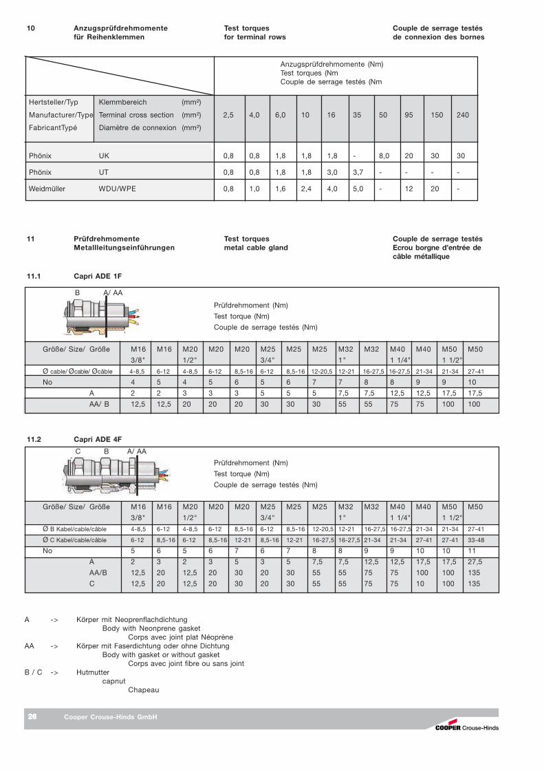
Cooper Crouse-Hinds GmbH2626262626
10 Anzugsprüfdrehmomente Test torques Couple de serrage testésfür Reihenklemmen for terminal rows de connexion des bornes
11 Prüfdrehmomente Test torques Couple de serrage testésMetallleitungseinführungen metal cable gland Ecrou borgne d’entrée de
câble métallique
Prüfdrehmoment (Nm)
Test torque (Nm)
Couple de serrage testés (Nm)
Größe/ Size/ Größe M16 M16 M20 M20 M20 M25 M25 M25 M32 M32 M40 M40 M50 M50
3/8" 1/2" 3/4" 1" 1 1/4" 1 1/2"
Ø B Kabel/cable/câble 4-8,5 6-12 4-8,5 6-12 8,5-16 6-12 8,5-16 12-20,5 12-21 16-27,5 16-27,5 21-34 21-34 27-41
Ø C Kabel/cable/câble 6-12 8,5-16 6-12 8,5-16 12-21 8,5-16 12-21 16-27,5 16-27,5 21-34 21-34 27-41 27-41 33-48
No 5 6 5 6 7 6 7 8 8 9 9 10 10 11
A 2 3 2 3 5 3 5 7,5 7,5 12,5 12,5 17,5 17,5 27,5
AA/B 12,5 20 12,5 20 30 20 30 55 55 75 75 100 100 135
C 12,5 20 12,5 20 30 20 30 55 55 75 75 10 100 135
11.2 Capri ADE 4F
A -> Körper mit NeoprenflachdichtungBody with Neonprene gasket
Corps avec joint plat NéoprèneAA -> Körper mit Faserdichtung oder ohne Dichtung
Body with gasket or without gasketCorps avec joint fibre ou sans joint
B / C -> Hutmuttercapnut
Chapeau
C B A/ AA
Prüfdrehmoment (Nm)
Test torque (Nm)
Couple de serrage testés (Nm)
Größe/ Size/ Größe M16 M16 M20 M20 M20 M25 M25 M25 M32 M32 M40 M40 M50 M50
3/8" 1/2" 3/4" 1" 1 1/4" 1 1/2"
Ø cable/ Øcable/ Øcâble 4-8,5 6-12 4-8,5 6-12 8,5-16 6-12 8,5-16 12-20,5 12-21 16-27,5 16-27,5 21-34 21-34 27-41
No 4 5 4 5 6 5 6 7 7 8 8 9 9 10
A 2 2 3 3 3 5 5 5 7,5 7,5 12,5 12,5 17,5 17,5
AA/ B 12,5 12,5 20 20 20 30 30 30 55 55 75 75 100 100
11.1 Capri ADE 1F
B A/ AA
Anzugsprüfdrehmomente (Nm)Test torques (NmCouple de serrage testés (Nm
Hertsteller/Typ Klemmbereich (mm²)
Manufacturer/Type Terminal cross section (mm²) 2,5 4,0 6,0 10 16 35 50 95 150 240
FabricantTypé Diamètre de connexion (mm²)
Phönix UK 0,8 0,8 1,8 1,8 1,8 - 8,0 20 30 30
Phönix UT 0,8 0,8 1,8 1,8 3,0 3,7 - - - -
Weidmüller WDU/WPE 0,8 1,0 1,6 2,4 4,0 5,0 - 12 20 -

Cooper Crouse-Hinds GmbH 2727272727
11.4 Capri CMDL
Prüfdrehmoment (Nm)
Test torque (Nm)
Couple de serrage testés (Nm)
Größe/ Size/ Größe M10 M12 M16 M20 M25 M32 M40 M50 M63 1/2" 3/4" 1"
Ø Kabel/Øcable/ Øcâble 1,5-5 4-8 6-11 7,5-13 12,5-18 17,5-25 24,5-33,5 33-43 42,5-55 7,5-13 12,5-18 17,5-25
No 3 4 5 6 7 8 9 10 11 6 7 8
A 2,5 3 5 6 10 17,5 27,5 40 7,5 6 10 17,5
AA/ B 10 15 25 27,5 45 85 135 200 55 27,5 45 85
Prüfdrehmoment (Nm)
Test torque (Nm)
Couple de serrage testés (Nm)
Größe/ Size/ Größe M20 M20 M20 M20 M20 M25 M32 M32 M50
Ø B Kabel/cable/câble 6,5-10,5 3-8 11,5-15 7-12 3-8 11-16,5 22-27,5 16-23 30-38
Ø C Kabel/cable/câble 10,5-17 5-11 13-21 13-21 7,5-14 18-27,5 23,5-33,5 23,5-33,5 40-53
No 5 5 6 6 6 7 8 8 10
A 7,5 7,5 10 10 10 15 27,5 27,5 50
B 25 25 35 35 35 55 90 90 175
C 7,5 7,5 10 10 10 15 27,5 27,5 50
11.3 Capri ADL 1F/4F
B A/ AA
A -> Körper mit NeoprenflachdichtungBody with Neonprene gasket
Corps avec joint plat NéoprèneAA -> Körper mit Faserdichtung oder ohne Dichtung
Body with gasket or without gasketCorps avec joint fibre ou sans joint
B / C -> Hutmuttercapnut
Chapeau
C B A
11 Prüfdrehmomente Test torques Couple de serrage testésMetallleitungseinführungen metal cable gland Ecrou borgne d’entrée de
câble métallique

GH
G 4
40 7
008
P00
01 D
/E/F
/ (L)
Auf
lage
/45.
11/Z
I
COOPER Crouse-Hinds GmbHCOOPER Crouse-Hinds GmbHCOOPER Crouse-Hinds GmbHCOOPER Crouse-Hinds GmbHCOOPER Crouse-Hinds GmbH
Neuer Weg - Nord 49D 69412 Eberbach / GermanyFone +49 (0 )6271 / 806-500Fax +49 (0 )6271 / 806-476Internet: www.CEAG.deE-Mail: [email protected]