application-oriented protocols for wireless sensor networks
TRANSCRIPT
Università degli Studi di PaviaScuola di Dottorato in Scienze dell’Ingegneria
Corso in Ingegneria Informatica, Elettronica ed Elettrica - XXIII Ciclo
Application-oriented Protocolsfor Wireless Sensor Networks
Emanuele Goldoni
Supervised byProf. Paolo Gamba


a Flavia


Questo lavoro non sarebbe stato possibile senza il generso sostegno della FondazioneUniversità di Mantova e della Fondazione Cariverona, che hanno rispettivamenteospitato le mie attività di ricerca nel laboratorio Elettronica e Telecomunicazionipresente presso la sede mantovana e finanziato il mio dottorato con una borsa sulle“Reti di sensori wireless per il monitoraggio, il controllo e la sicurezza”.
Contents
Contents v
Abstract 1
1 Wireless Sensor Networks 21.1 Introduction . . . . . . . . . . . . . . . . . . . . . . . . . . . . . . . . 21.2 MAC Protocols for WSNs . . . . . . . . . . . . . . . . . . . . . . . . 4
1.2.1 Traditional protocols . . . . . . . . . . . . . . . . . . . . . . . 51.2.2 Preamble sampling methods . . . . . . . . . . . . . . . . . . . 71.2.3 Common active periods techniques . . . . . . . . . . . . . . . 91.2.4 Scheduled protocols . . . . . . . . . . . . . . . . . . . . . . . 101.2.5 Hybrid protocols . . . . . . . . . . . . . . . . . . . . . . . . . 131.2.6 Real-time protocols . . . . . . . . . . . . . . . . . . . . . . . . 14
1.3 Interconnecting Wireless Sensor Networks . . . . . . . . . . . . . . . 181.4 Contribution of the Thesis . . . . . . . . . . . . . . . . . . . . . . . . 20
2 Real-time Structural Monitoring 222.1 Introduction . . . . . . . . . . . . . . . . . . . . . . . . . . . . . . . . 222.2 WSNs for Structural Monitoring . . . . . . . . . . . . . . . . . . . . 232.3 An Overview of the PRISM Protocol . . . . . . . . . . . . . . . . . . 24
2.3.1 TDMA Scheduling . . . . . . . . . . . . . . . . . . . . . . . . 252.3.2 Bursty Transmission . . . . . . . . . . . . . . . . . . . . . . . 252.3.3 Network Synchronization . . . . . . . . . . . . . . . . . . . . 25
2.4 PRISM in Single-Hop Networks . . . . . . . . . . . . . . . . . . . . . 262.4.1 Theoretical Analysis . . . . . . . . . . . . . . . . . . . . . . . 262.4.2 Synchronization issues . . . . . . . . . . . . . . . . . . . . . . 27
2.5 PRISM in Multi-hop Networks . . . . . . . . . . . . . . . . . . . . . 272.5.1 Theoretical Analysis . . . . . . . . . . . . . . . . . . . . . . . 282.5.2 Synchronization issues . . . . . . . . . . . . . . . . . . . . . . 30
2.6 Numerical Experiments . . . . . . . . . . . . . . . . . . . . . . . . . 312.7 Experimental Evaluation . . . . . . . . . . . . . . . . . . . . . . . . . 31
2.7.1 The W-TREMORS system . . . . . . . . . . . . . . . . . . . 332.7.2 Testbed Results . . . . . . . . . . . . . . . . . . . . . . . . . . 35
2.8 Conclusions . . . . . . . . . . . . . . . . . . . . . . . . . . . . . . . . 37
v
CONTENTS vi
3 Cross-layer Environmental Monitoring 383.1 Introduction . . . . . . . . . . . . . . . . . . . . . . . . . . . . . . . . 383.2 The CERTO Protocol . . . . . . . . . . . . . . . . . . . . . . . . . . 39
3.2.1 Structure of the CERTO Superframe . . . . . . . . . . . . . . 403.2.2 Routing in CERTO . . . . . . . . . . . . . . . . . . . . . . . 41
3.3 Configuration of CERTO . . . . . . . . . . . . . . . . . . . . . . . . 453.3.1 Tree-topology thresholds . . . . . . . . . . . . . . . . . . . . . 453.3.2 Reconnection attempts . . . . . . . . . . . . . . . . . . . . . . 453.3.3 Superframe duration . . . . . . . . . . . . . . . . . . . . . . . 45
3.4 Experimental evaluation . . . . . . . . . . . . . . . . . . . . . . . . . 473.4.1 Network configuration parameters . . . . . . . . . . . . . . . 483.4.2 Nodes placement strategies . . . . . . . . . . . . . . . . . . . 493.4.3 Network deployment . . . . . . . . . . . . . . . . . . . . . . . 50
3.5 Conclusions . . . . . . . . . . . . . . . . . . . . . . . . . . . . . . . . 51
4 A RESTful Interface for WSNs 534.1 Introduction . . . . . . . . . . . . . . . . . . . . . . . . . . . . . . . . 534.2 REST for Environmental Monitoring . . . . . . . . . . . . . . . . . . 54
4.2.1 The Environmental Database . . . . . . . . . . . . . . . . . . 554.2.2 The RESTful interface . . . . . . . . . . . . . . . . . . . . . . 554.2.3 The integration with CERTO protocol . . . . . . . . . . . . . 584.2.4 Preliminary Results and Lessons Learned . . . . . . . . . . . 60
4.3 REST for Structural Monitoring . . . . . . . . . . . . . . . . . . . . 614.4 Conclusions . . . . . . . . . . . . . . . . . . . . . . . . . . . . . . . . 63
5 Conclusions 64
Bibliography 66
Abstract
Initially motivated by military applications, Wireless Sensor Networks (WSNs)are now applied to a number of different domains, such as environmental andstructural monitoring, healthcare, production, emergency rescue operation and homeautomation. This wide variety of possible applications results in vastly varyingrequirements and characteristics, and raises a number of critical issues which haveto be addressed during the design of a sensor network – cost, power consumption,scalability, fault tolerance, etc.
Each of these issues has an influence on the design of the hardware and softwareparts of new sensing platforms, and drives the research in telecommunications withrespect to these systems. Specifically, to meet the general trend towards diversification,in recent years several different Medium Access Control, routing, power managementand data gathering protocols have been designed for each possible WSN application.However, despite the existence of several solutions for reliable real-time data deliveryin sensor networks, most of the existing works require the optimization of one ormore network parameters, failing to heed the realistic requirements and constraintsof the target domain. Moreover, most of past works have neglected a flexible yetrobust way to interconnect heterogeneous WSNs and expose them to the users.
The aim of this thesis is threefold: first, to propose a new protocol for real-timesynchronous acquisitions in multi-hop wireless sensor networks which is able toaccommodate for different types of acquisitions, and therefore of applications. Thisnovel protocol is suitable for critical applications – it can define the maximumnumber of nodes and the data-rate in a flexible manner, ensuring that the timeconstraints and the delivery of data are satisfied within a given deadline.
Second, the thesis proposes a cross-layer protocol for slow data reporting inenvironmental applications. This solution combines new ideas with features inspiredby existing protocols, and integrates the routing layer with the MAC mechanism ina flexible and energy-wise scheduled rendez-vous mechanism.
Finally, effective guidelines are provided for designing a novel interface for wirelesssensor networks based on standard protocols and a lightweight software architecturalstyle. A RESTful web service is designed in order to expose the data acquired fromone or more sensor networks using the HTTP protocol and the principles of REST.The resulting solution has been not only analyzed theoretically, but also tested inreal WSN implementations. Specifically, the system has been used for presentingthe result gathered by the sensor network for real-time monitoring of structures andbuildings described previously. In addition, the same RESTful interface has beencoupled with the second proposed protocol to assist in continuous monitoring ofenvironmental, slowly varying parameters.
1
Chapter 1
Wireless Sensor Networks
1.1 IntroductionThe concept of Wireless Sensor Network (WSN) usually refers to a network which ismade of hundreds or thousands of sensor nodes, densely deployed in an unattendedenvironment. These nodes have the capabilities of sensing, wireless communicating,collecting and disseminating data [1]. Typically, a sensor node consists of sensing,computing, communication, actuation, and power components. These componentsare integrated and packaged in a small board, usually no larger than a few cubiccentimeters. They are also supposed to employ low-power networking and electronictechnologies to last for years with a low duty cycle working mode. Hence, such anetwork comes from the combination of sensing technologies, embedded techniques,distributed information processing, and communication mechanisms [2].
Initially motivated by military applications, WSNs are applied nowadays to anumber of different domains. For example, WSNs have been deployed on a widescale for environmental monitoring and habitat study [3, 4], in wild environments forsupporting emergency operations [5], in buildings for structural health monitoring[6, 7], in battlefields for security surveillance [8, 9], in houses to realize smart homes[10], in hospitals — or even over bodies — for patient monitoring [11, 2]. Although theso-called “smartdust” is still far from reality, a number of wireless sensor platformsare now commercially available – the recent advances in energy harvesting, MEMSsensors, and low-power design techniques have boosted the miniaturization of sensornodes and decreased significantly their production cost [12].
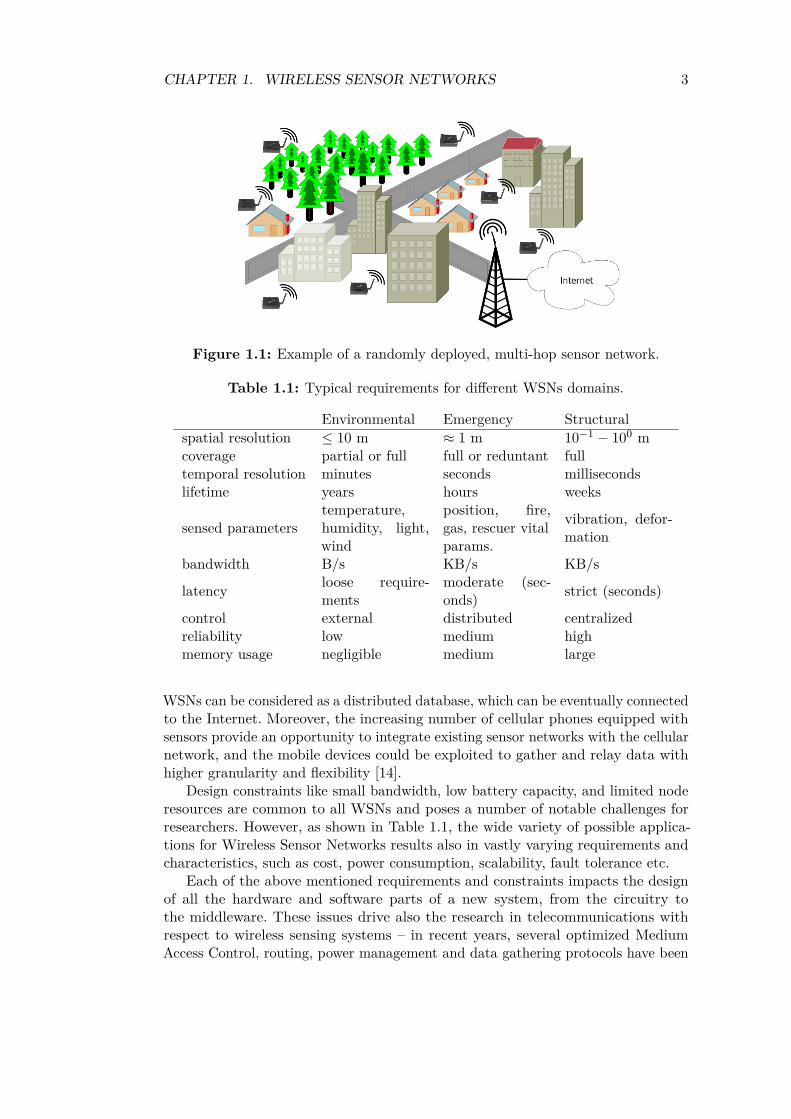
After the initial deployment, either random or ad-hoc, sensor nodes self-organizeinto an appropriate network infrastructure, often with multi-hop connections betweendevices similar to the one shown in Figure 1.1.
Then, the sensors start collecting information from the environment, using eithercontinuous or event-driven sampling modes. Time synchronization between nodescan be achieved using distributed or centralized methods [13]. Similarly, a node canalso obtain positioning information through the global positioning system (GPS) orlocal algorithms. The acquired data can be gathered from across the network, andthen appropriately processed in order to construct a global view of the monitoredphenomena [1]. In a typical scenario, users can retrieve information of interest froma WSN by injecting queries and gathering results from the so-called base stations (orsink nodes), which behave as an interface between users and the network. In this way,
2
CHAPTER 1. WIRELESS SENSOR NETWORKS 3
Figure 1.1: Example of a randomly deployed, multi-hop sensor network.
Table 1.1: Typical requirements for different WSNs domains.
Environmental Emergency Structuralspatial resolution ≤ 10 m ≈ 1 m 10−1 − 100 mcoverage partial or full full or reduntant fulltemporal resolution minutes seconds millisecondslifetime years hours weeks
sensed parameterstemperature,humidity, light,wind
position, fire,gas, rescuer vitalparams.
vibration, defor-mation
bandwidth B/s KB/s KB/s
latency loose require-ments
moderate (sec-onds) strict (seconds)
control external distributed centralizedreliability low medium highmemory usage negligible medium large
WSNs can be considered as a distributed database, which can be eventually connectedto the Internet. Moreover, the increasing number of cellular phones equipped withsensors provide an opportunity to integrate existing sensor networks with the cellularnetwork, and the mobile devices could be exploited to gather and relay data withhigher granularity and flexibility [14].
Design constraints like small bandwidth, low battery capacity, and limited noderesources are common to all WSNs and poses a number of notable challenges forresearchers. However, as shown in Table 1.1, the wide variety of possible applica-tions for Wireless Sensor Networks results also in vastly varying requirements andcharacteristics, such as cost, power consumption, scalability, fault tolerance etc.
Each of the above mentioned requirements and constraints impacts the designof all the hardware and software parts of a new system, from the circuitry tothe middleware. These issues drive also the research in telecommunications withrespect to wireless sensing systems – in recent years, several optimized MediumAccess Control, routing, power management and data gathering protocols have been

CHAPTER 1. WIRELESS SENSOR NETWORKS 4
designed for the WSN domain [15].Specifically to the aims of our research, in the last years there has been a growing
attention to Medium Access Control protocols. These protocols rule how nodesaccess the shared radio channel in order to communicate with neighbours, and theireffectiveness in minimizing interferences and collisions deeply impacts the efficiencyof the whole sensor network. Although a number of well-established mechanismsare available nowadays, the design of embedded, large-scale distributed, dense, andbattery-powered wireless sensor nodes challenges traditional MAC approaches andcalls for new solutions.
Obviously, an efficient MAC protocol is not sufficient by itself, and must becoupled with an appropriate physical layer and an optimized routing protocol. Finally,there must exist a flexible yet robust way to interconnect heterogeneous WSNs andexpose them to the users – a wireless sensor network is mostly useless if the dataand the nodes are not accessible from the outside. Hence, another crucial challengein the quest for a successful Wireless Sensor Network is the design of an effectiveinterface for fast, reliable external access.
1.2 MAC Protocols for WSNsA number of aspects drive the design of a MAC protocol for WSNs, among which theenergy constraint, the low computational power and the memory of the nodes standout. Hence, an effective MAC protocol for wireless sensor networks must be powerefficient, minimize collisions, be implementable with a small code footprint andlimited memory requirements, be efficient for the target application, and be tolerantto changing radio frequency and networking condition. Moreover, the protocol mustalso take into account that the network traffic is generally in one direction, frommultiple nodes to a sink, and may have sporadic or periodic transmissions.
The energy dissipation of a MAC protocol depends on the ability to avoid threemain potential unwanted events: collisions, overhearing, and overhead [16, 17]. Sincethese factors are common to most of wireless systems, a few of the traditionalapproaches used in wireless networks have also been proposed for WSNs with minoror no variations. However, wireless sensing applications often require dedicatedprotocols highly optimized and tailored for the given task.
Ye et al [18] presented MAC protocols for Wireless Sensor Networks dividing theminto two classes: time division and contention-based protocols. A similar approachis used also in [19]: the protocols are divided in three classes, namely collision-free,sleep-scheduled, and asynchronous, depending on the general methods they use toachieve energy efficiency. In [20] a general taxonomy is used to classify the MACtechniques into a bi-dimensional matrix, according to their layering and channelaccess method: cross-layer and solitary on one side, contention-based, hybrid, andscheduled on the other. Similarly, an other possible categorization criteria couldrelate to the network topology, which can be either hierarchical or meshed [20]. Thetarget application is used instead by Bachir et al. in [16] to divide the protocols intothree main classes depending on the traffic profile: scheduled protocols for periodichigh-load traffic, common active periods mechanism for medium-load traffic scenarios,and preamble sampling protocols for rare reporting events. Moreover, a special classis devoted to hybrid techniques, which combine the benefits of different protocols
CHAPTER 1. WIRELESS SENSOR NETWORKS 5
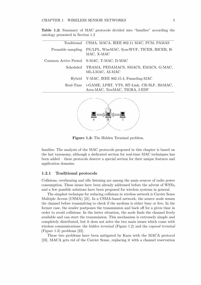
Table 1.2: Summary of MAC protocols divided into “families” according theontology presented in Section 1.2
Traditional CSMA, MACA, IEEE 802.11 MAC, PCM, PAMAS
Preamble sampling PS/LPL, WiseMAC, SyncWUF, TICER, RICER, B-MAC, X-MAC
Common Active Period S-MAC, T-MAC, D-MAC
Scheduled TRAMA, PEDAMACS, SMACS, EMACS, G-MAC,ML-LMAC, AI-MAC
Hybrid Y-MAC, IEEE 802.15.4, Funneling-MAC
Real-Time i-GAME, LPRT, VTS, RT-Link, CR-SLF, BitMAC,Area-MAC, TreeMAC, TIGRA, I-EDF
Figure 1.2: The Hidden Terminal problem.
families. The analysis of the MAC protocols proposed in this chapter is based onthe last taxonomy, although a dedicated section for real-time MAC techniques hasbeen added – these protocols deserve a special section for their unique features andapplication domains.
1.2.1 Traditional protocols
Collisions, overhearing and idle listening are among the main sources of radio powerconsumption. These issues have been already addressed before the advent of WSNs,and a few possible solutions have been proposed for wireless systems in general.
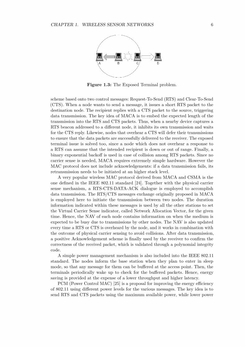
The simplest technique for reducing collisions in wireless network is Carrier SenseMultiple Access (CSMA) [21]. In a CSMA-based network, the source node sensesthe channel before transmitting to check if the medium is either busy or free. In theformer case, the sender postpones the transmission and back off for a given time inorder to avoid collisions. In the latter situation, the node finds the channel freelyavailable and can start the transmission. This mechanism is extremely simple andcompletely distributed, but it does not solve the two main issues which come withwireless communications: the hidden terminal (Figure 1.2) and the exposed terminal(Figure 1.3) problems [22].
These two problems have been mitigated by Karn with the MACA protocol[23]. MACA gets rid of the Carrier Sense, replacing it with a channel reservation
CHAPTER 1. WIRELESS SENSOR NETWORKS 6
Figure 1.3: The Exposed Terminal problem.
scheme based onto two control messages: Request-To-Send (RTS) and Clear-To-Send(CTS). When a node wants to send a message, it issues a short RTS packet to thedestination node. The recipient replies with a CTS packet to the source, triggeringdata transmission. The key idea of MACA is to embed the expected length of thetransmission into the RTS and CTS packets. Thus, when a nearby device captures aRTS beacon addressed to a different node, it inhibits its own transmission and waitsfor the CTS reply. Likewise, nodes that overhear a CTS will defer their transmissionsto ensure that the data packets are successfully delivered to the receiver. The exposedterminal issue is solved too, since a node which does not overhear a response toa RTS can assume that the intended recipient is down or out of range. Finally, abinary exponential backoff is used in case of collision among RTS packets. Since nocarrier sense is needed, MACA requires extremely simple hardware. However theMAC protocol does not include acknowledgements: if a data transmission fails, itsretransmission needs to be initiated at an higher stack level.
A very popular wireless MAC protocol derived from MACA and CSMA is theone defined in the IEEE 802.11 standard [24]. Together with the physical carriersense mechanism, a RTS-CTS-DATA-ACK dialogue is employed to accomplishdata transmission. The RTS/CTS messages exchange originally proposed in MACAis employed here to initiate the transmission between two nodes. The durationinformation indicated within these messages is used by all the other stations to setthe Virtual Carrier Sense indicator, called Network Allocation Vector, for the giventime. Hence, the NAV of each node contains information on when the medium isexpected to be busy due to transmissions by other nodes. The NAV is also updatedevery time a RTS or CTS is overheard by the node, and it works in combination withthe outcome of physical carrier sensing to avoid collisions. After data transmission,a positive Acknowledgement scheme is finally used by the receiver to confirm thecorrectness of the received packet, which is validated through a polynomial integritycode.
A simple power management mechanism is also included into the IEEE 802.11standard. The nodes inform the base station when they plan to enter in sleepmode, so that any message for them can be buffered at the access point. Then, theterminals periodically wake up to check for the buffered packets. Hence, energysaving is provided at the expense of a lower throughput and higher latency.
PCM (Power Control MAC) [25] is a proposal for improving the energy efficiencyof 802.11 using different power levels for the various messages. The key idea is tosend RTS and CTS packets using the maximum available power, while lower power

CHAPTER 1. WIRELESS SENSOR NETWORKS 7
Figure 1.4: The basic working principle of Preamble Sampling / LPL (from [19]).
levels are employed to send the data and the acknowledgements. The minimumpower required to communicate between the sender and receiver is chosen accordingto the received signal strength of the RTS/CTS packets. The real problem withPCM is the significant impact of fading phenomena over low-power transmissions,which makes quite hard to obtain an accurate estimation of actual signal strength.
The MACA idea has been extended in Power Aware Multi-Access protocol withSignaling (PAMAS) [26], where the RTS/CTS signaling is carried out on a dedicatedchannel, separated from the radio channel used for data exchange. While a node isreceiving a data packet, it broadcasts control signals onto the secondary channel toindicate the length of the ongoing transmission. The other nodes go to sleep wheneverthey can neither receive nor transmit successfully. Moreover, if a transmission isstarted while a node is in sleep mode, the secondary channel is used to determinehow long it can go back again to sleep.
While all these canonical solutions provide ways to save energy on overhearing,further energy efficiency is possible by reducing idle receptions. The key challengehere is to allow receivers to sleep for the majority of their time, while still ensuringthat they will be awake and ready for reception when a packet intended for themwill be transmitted. According to the methods used to solve this problem and to thetraffic generated by the system, there are essentially three classes of MAC protocolsspecifically designed for sensor networks, as discussed in the following sections.
1.2.2 Preamble sampling methods
One of the possible tasks of a WSN is the reporting of rare or aperiodic events.Intrusion detection applications fall in this category: the sensor node must detectspecific events, and does not communicate unless an specific action is detected.Similarly, nodes used for metering applications operate at very low duty cyclesand report measurements to the central station sporadically. In all these scenariosPreamble Sampling [27], sometimes also called Low Power Listening (LPL) [28], isan efficient way of managing the channel access.
Differently from the other techniques, the nodes in a network based on preamblesampling do not share a common wake-up schedule. Looking at the big picture,each node is in sleep state most of the time and sometimes, independently from theother sensors, it wakes up for a short period of time to receive or transmit data.Since the nodes are not synchronized, a preamble signal is used to inform the otherdevices that a transmission is going to happen – as a matter of facts, the preambleneeds to last enough to make sure that all potential receivers detect the preamble.A streamlined diagram of this wake up mechanism is shown in Figure 1.4.
CHAPTER 1. WIRELESS SENSOR NETWORKS 8
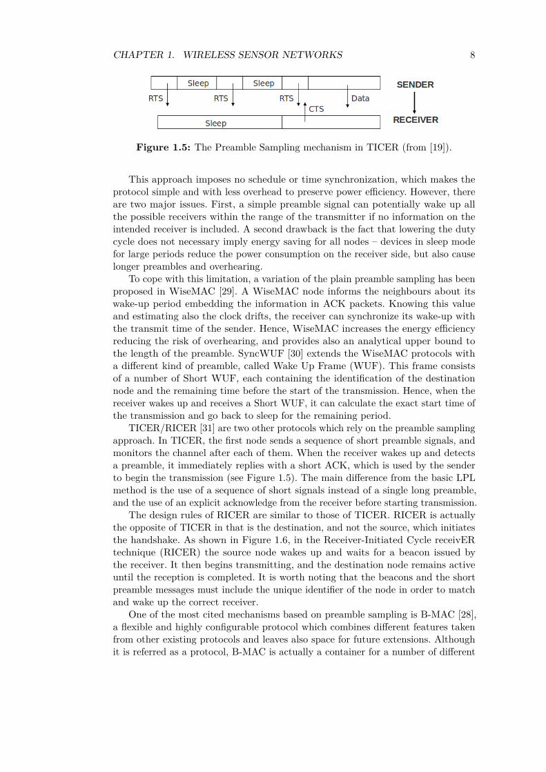
Figure 1.5: The Preamble Sampling mechanism in TICER (from [19]).
This approach imposes no schedule or time synchronization, which makes theprotocol simple and with less overhead to preserve power efficiency. However, thereare two major issues. First, a simple preamble signal can potentially wake up allthe possible receivers within the range of the transmitter if no information on theintended receiver is included. A second drawback is the fact that lowering the dutycycle does not necessary imply energy saving for all nodes – devices in sleep modefor large periods reduce the power consumption on the receiver side, but also causelonger preambles and overhearing.
To cope with this limitation, a variation of the plain preamble sampling has beenproposed in WiseMAC [29]. A WiseMAC node informs the neighbours about itswake-up period embedding the information in ACK packets. Knowing this valueand estimating also the clock drifts, the receiver can synchronize its wake-up withthe transmit time of the sender. Hence, WiseMAC increases the energy efficiencyreducing the risk of overhearing, and provides also an analytical upper bound tothe length of the preamble. SyncWUF [30] extends the WiseMAC protocols witha different kind of preamble, called Wake Up Frame (WUF). This frame consistsof a number of Short WUF, each containing the identification of the destinationnode and the remaining time before the start of the transmission. Hence, when thereceiver wakes up and receives a Short WUF, it can calculate the exact start time ofthe transmission and go back to sleep for the remaining period.
TICER/RICER [31] are two other protocols which rely on the preamble samplingapproach. In TICER, the first node sends a sequence of short preamble signals, andmonitors the channel after each of them. When the receiver wakes up and detectsa preamble, it immediately replies with a short ACK, which is used by the senderto begin the transmission (see Figure 1.5). The main difference from the basic LPLmethod is the use of a sequence of short signals instead of a single long preamble,and the use of an explicit acknowledge from the receiver before starting transmission.
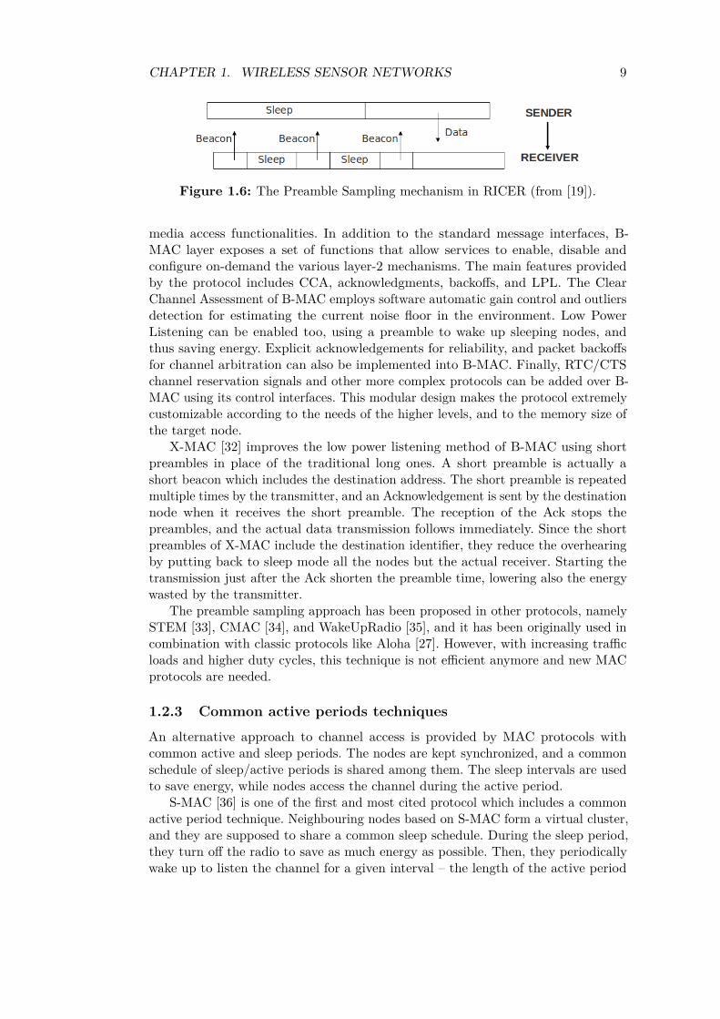
The design rules of RICER are similar to those of TICER. RICER is actuallythe opposite of TICER in that is the destination, and not the source, which initiatesthe handshake. As shown in Figure 1.6, in the Receiver-Initiated Cycle receivERtechnique (RICER) the source node wakes up and waits for a beacon issued bythe receiver. It then begins transmitting, and the destination node remains activeuntil the reception is completed. It is worth noting that the beacons and the shortpreamble messages must include the unique identifier of the node in order to matchand wake up the correct receiver.
One of the most cited mechanisms based on preamble sampling is B-MAC [28],a flexible and highly configurable protocol which combines different features takenfrom other existing protocols and leaves also space for future extensions. Althoughit is referred as a protocol, B-MAC is actually a container for a number of different
CHAPTER 1. WIRELESS SENSOR NETWORKS 9
Figure 1.6: The Preamble Sampling mechanism in RICER (from [19]).
media access functionalities. In addition to the standard message interfaces, B-MAC layer exposes a set of functions that allow services to enable, disable andconfigure on-demand the various layer-2 mechanisms. The main features providedby the protocol includes CCA, acknowledgments, backoffs, and LPL. The ClearChannel Assessment of B-MAC employs software automatic gain control and outliersdetection for estimating the current noise floor in the environment. Low PowerListening can be enabled too, using a preamble to wake up sleeping nodes, andthus saving energy. Explicit acknowledgements for reliability, and packet backoffsfor channel arbitration can also be implemented into B-MAC. Finally, RTC/CTSchannel reservation signals and other more complex protocols can be added over B-MAC using its control interfaces. This modular design makes the protocol extremelycustomizable according to the needs of the higher levels, and to the memory size ofthe target node.
X-MAC [32] improves the low power listening method of B-MAC using shortpreambles in place of the traditional long ones. A short preamble is actually ashort beacon which includes the destination address. The short preamble is repeatedmultiple times by the transmitter, and an Acknowledgement is sent by the destinationnode when it receives the short preamble. The reception of the Ack stops thepreambles, and the actual data transmission follows immediately. Since the shortpreambles of X-MAC include the destination identifier, they reduce the overhearingby putting back to sleep mode all the nodes but the actual receiver. Starting thetransmission just after the Ack shorten the preamble time, lowering also the energywasted by the transmitter.
The preamble sampling approach has been proposed in other protocols, namelySTEM [33], CMAC [34], and WakeUpRadio [35], and it has been originally used incombination with classic protocols like Aloha [27]. However, with increasing trafficloads and higher duty cycles, this technique is not efficient anymore and new MACprotocols are needed.
1.2.3 Common active periods techniques
An alternative approach to channel access is provided by MAC protocols withcommon active and sleep periods. The nodes are kept synchronized, and a commonschedule of sleep/active periods is shared among them. The sleep intervals are usedto save energy, while nodes access the channel during the active period.
S-MAC [36] is one of the first and most cited protocol which includes a commonactive period technique. Neighbouring nodes based on S-MAC form a virtual cluster,and they are supposed to share a common sleep schedule. During the sleep period,they turn off the radio to save as much energy as possible. Then, they periodicallywake up to listen the channel for a given interval – the length of the active period
CHAPTER 1. WIRELESS SENSOR NETWORKS 10
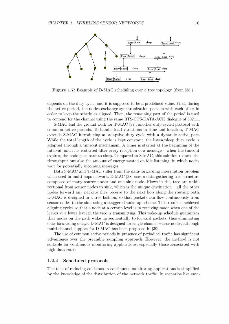
Figure 1.7: Example of D-MAC scheduling over a tree topology (from [38]).
depends on the duty cycle, and it is supposed to be a predefined value. First, duringthe active period, the nodes exchange synchronization packets with each other inorder to keep the schedules aligned. Then, the remaining part of the period is usedto contend for the channel using the same RTS-CTS-DATA-ACK dialogue of 802.11.
S-MAC laid the ground work for T-MAC [37], another duty-cycled protocol withcommon active periods. To handle load variations in time and location, T-MACextends S-MAC introducing an adaptive duty cycle with a dynamic active part.While the total length of the cycle is kept constant, the listen/sleep duty cycle isadapted through a timeout mechanism. A timer is started at the beginning of theinterval, and it is restarted after every reception of a message – when the timeoutexpires, the node goes back to sleep. Compared to S-MAC, this solution reduces thethroughput but also the amount of energy wasted on idle listening, in which nodeswait for potentially incoming messages.
Both S-MAC and T-MAC suffer from the data-forwarding interruption problemwhen used in multi-hops network. D-MAC [38] uses a data gathering tree structurecomposed of many source nodes and one sink node. Flows in this tree are unidi-rectional from sensor nodes to sink, which is the unique destination – all the othernodes forward any packets they receive to the next hop along the routing path.D-MAC is designed in a tree fashion, so that packets can flow continuously fromsensor nodes to the sink using a staggered wake-up scheme. This result is achievedaligning cycles so that a node at a certain level is in receiving mode when one of theleaves at a lower level in the tree is transmitting. This wake-up schedule guaranteesthat nodes on the path wake up sequentially to forward packets, thus eliminatingdata-forwarding delays. D-MAC is designed for single-channel sensor nodes, althoughmulti-channel support for D-MAC has been proposed in [39].
The use of common active periods in presence of periodical traffic has significantadvantages over the preamble sampling approach. However, the method is notsuitable for continuous monitoring applications, especially those associated withhigh-data rates.
1.2.4 Scheduled protocols
The task of reducing collisions in continuous-monitoring applications is simplifiedby the knowledge of the distribution of the network traffic. In scenarios like envi-
CHAPTER 1. WIRELESS SENSOR NETWORKS 11
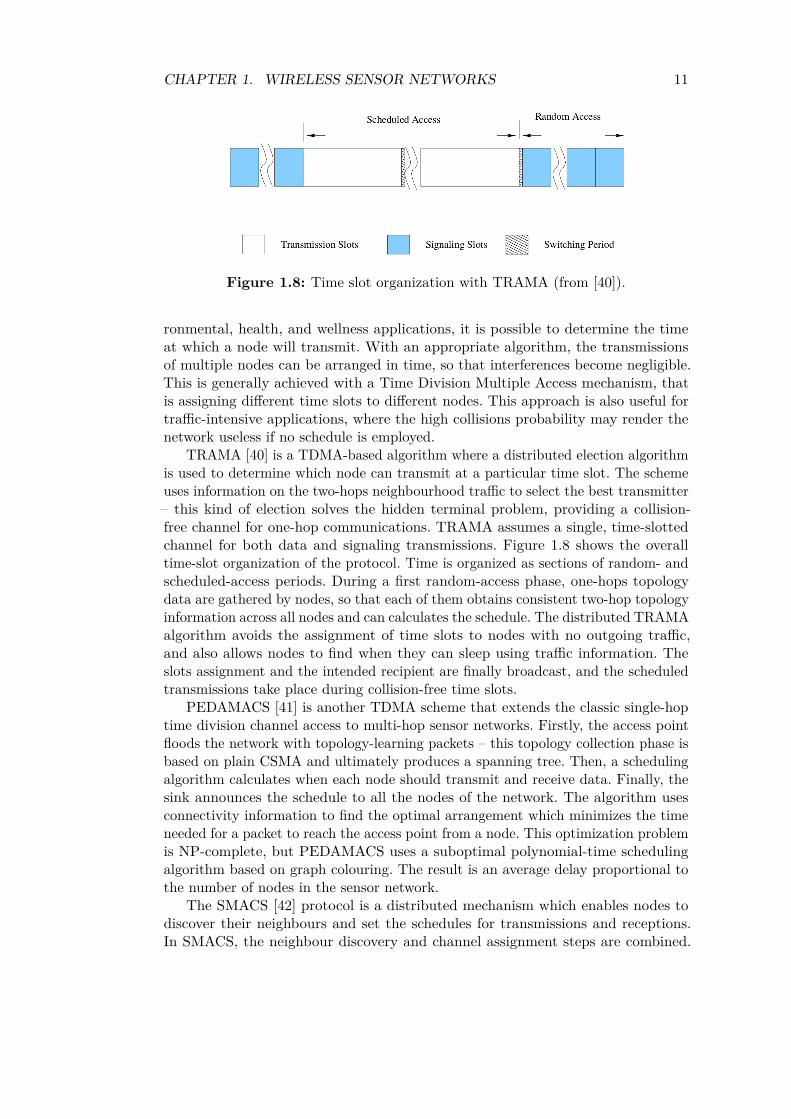
Figure 1.8: Time slot organization with TRAMA (from [40]).
ronmental, health, and wellness applications, it is possible to determine the timeat which a node will transmit. With an appropriate algorithm, the transmissionsof multiple nodes can be arranged in time, so that interferences become negligible.This is generally achieved with a Time Division Multiple Access mechanism, thatis assigning different time slots to different nodes. This approach is also useful fortraffic-intensive applications, where the high collisions probability may render thenetwork useless if no schedule is employed.
TRAMA [40] is a TDMA-based algorithm where a distributed election algorithmis used to determine which node can transmit at a particular time slot. The schemeuses information on the two-hops neighbourhood traffic to select the best transmitter– this kind of election solves the hidden terminal problem, providing a collision-free channel for one-hop communications. TRAMA assumes a single, time-slottedchannel for both data and signaling transmissions. Figure 1.8 shows the overalltime-slot organization of the protocol. Time is organized as sections of random- andscheduled-access periods. During a first random-access phase, one-hops topologydata are gathered by nodes, so that each of them obtains consistent two-hop topologyinformation across all nodes and can calculates the schedule. The distributed TRAMAalgorithm avoids the assignment of time slots to nodes with no outgoing traffic,and also allows nodes to find when they can sleep using traffic information. Theslots assignment and the intended recipient are finally broadcast, and the scheduledtransmissions take place during collision-free time slots.
PEDAMACS [41] is another TDMA scheme that extends the classic single-hoptime division channel access to multi-hop sensor networks. Firstly, the access pointfloods the network with topology-learning packets – this topology collection phase isbased on plain CSMA and ultimately produces a spanning tree. Then, a schedulingalgorithm calculates when each node should transmit and receive data. Finally, thesink announces the schedule to all the nodes of the network. The algorithm usesconnectivity information to find the optimal arrangement which minimizes the timeneeded for a packet to reach the access point from a node. This optimization problemis NP-complete, but PEDAMACS uses a suboptimal polynomial-time schedulingalgorithm based on graph colouring. The result is an average delay proportional tothe number of nodes in the sensor network.
The SMACS [42] protocol is a distributed mechanism which enables nodes todiscover their neighbours and set the schedules for transmissions and receptions.In SMACS, the neighbour discovery and channel assignment steps are combined.

CHAPTER 1. WIRELESS SENSOR NETWORKS 12
Figure 1.9: Structure of a G-MAC frame (from [44]).
Nodes which can hear each other establish a so-called “communication link”, whichconsists of two time slots at a randomly chosen frequency. Such a scheme avoidsthe requirement for network-wide synchronization, although a local synchronizationbetween neighbours is still needed. Like other mentioned protocols, the nodes canbe put in sleep mode during idle time slots to save power.
A different TDMA based MAC scheme is EMACS [43]. EMACS divides time intoframes, frames into time slots, and each slot contains three sections: communicationrequest (CR), traffic control (TC), and data section. Each time slot can be assignedto only one network node – the other nodes can ask for data or notify the availabilityof packets for the owner of the time slot in the CR section. The owner of the slot,which finally decides which communication should take place in its slot, uses thetraffic control phase both to broadcast the schedule for its data section and to publishthe other sections it is going to listening. After this step, the transmission of theactual data packet follows. As expected, power saving is achieved putting in sleepmode the node when no transmissions are expected.
G-MAC [44] operates on large sensor networks organized into smaller cluster,and eliminates cluster-wide idle listening to obtain significant energy savings. Thefirst phase of a TDMA frame cycle in a cluster is the collection period, when thecluster coordinator (gateway) collects both local and non-local network traffic. Afterall transactions have been completed, the gateway attempts to forward all traffic outof the cluster and then moves to sleep state. Then, the distribution period begins,with all nodes waking up and receiving a synchronization message from the gateway.This message embeds information about the current time, the next collection period,the next distribution period, and the schedule of messages transactions betweencluster nodes. At the end of the schedule, the gateway will wake up and use theremaining distribution period to exchange inter-network traffic with other gateways.When the contention/collection period begins again, only nodes with awaiting trafficwake up and request a scheduled cycle. The structure of a cyclic G-MAC frame isshown in Figure 1.9.
Other scheduled protocols take advantage of interference-free and contention-freeparallel transmissions on different channels to increase throughput in high-data rateapplication. For example, MC-LMAC [45] coordinates transmissions in time and overmultiple frequency channels – time is slotted, and each node is assigned the controlover a time slot to transmit on a particular channel. Similarly, other protocols like
CHAPTER 1. WIRELESS SENSOR NETWORKS 13
LMAC [46] and AI-LMAC [47] are examples of other time and channel-scheduledprotocols which introduce additional mechanisms to adapt the assignments withvarying network traffics or loads.
However, looking at the big picture, the scalability and convergence time ofthe scheduling algorithms pose severe issues with an increasing number of nodes.Moreover, the problem is critical in fully-meshed network, where the lack of a centralnode burden the sensors with the computation for the scheduling.
1.2.5 Hybrid protocols
Although the taxonomy adopted above is quite general, not all protocols for WSNscan be clearly classified in one of the three previous classes. The main reason isthat some protocols combine the main features of different approaches into a singlemethod. The resulting solutions are hybrid protocols which can adapt their behaviouraccording to the scenario and the current status of the network.
Y-MAC [48] is an example of hybrid protocol which combines preamble samplingand scheduling of transmissions. The basic channel access is based on time-division,with the time frame composed of time slots long enough to transmit one datamessage. However, time slots are not assigned to the senders but to the receivers –at the beginning of each time slot, potential senders for the same receiver contendfor the channel. In Y-MAC, this medium access contention is based on low powerlistening. A contention window is started, and the nodes wishing to send a packetrandomly backoff within the contention window. The first node which goes backand finds the channel clear transmits a preamble until the end of the contentionwindow to suppress competing transmissions. Then, the receiver associated to thetime slot wakes up at the end of the contention window to receive data from thecontention winner. Unicast messages are initially exchanged on the base channel.This is energy efficient under light traffic conditions, since every node polls themedium only during the broadcast time slots and its own unicast receive time slot.However, many unicast messages may have to wait in the queue, or be dropped inheavy traffic scenarios. If multiple packets need to be transmitted, then the receiverand all the potential senders hop to a new channel according to a pre-determinedfrequency-hopping sequence.
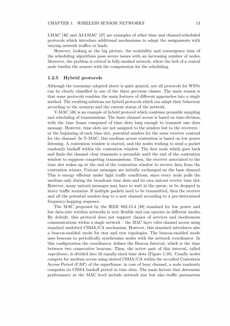
The MAC proposed by the IEEE 802.15.4 [49] standard for low power andlow data-rate wireless networks is very flexible and can operate in different modes.By default, this protocol does not support classes of services and isochronouscommunications within a single network – the MAC layer rules channel access usingstandard unslotted CSMA/CA mechanism. However, this standard introduces alsoa beacon-enabled mode for star and tree topologies. The beacon-enabled modeuses beacons to periodically synchronize nodes with the network coordinator. Inthis configuration the coordinator defines the Beacon Interval, which is the timebetween two consecutive beacons. Then, the active part of this interval, calledsuperframe, is divided into 16 equally-sized time slots (Figure 1.10). Usually nodescompete for medium access using slotted CSMA/CA within the so-called ContentionAccess Period (CAP) of the superframe: in case of busy channel, a node randomlycomputes its CSMA backoff period in time slots. The main factors that determineperformance at the MAC level include network size but also traffic parameters
CHAPTER 1. WIRELESS SENSOR NETWORKS 14
Figure 1.10: IEEE 802.15.4 superframe structure (from [49]).
such as packet arrival rates and duration of sleep periods. The Beacon Interval andSuperframe Duration values have a large impact on the network performance, and thevalues should be adaptively adjusted too, according to the network traffic conditions.Moreover, the standard allows a Contention-Free Period (CFP) within the superframe.This option is activated upon request to the coordinator for allocating time slotsdepending on the node’s requirements. The PAN coordinator checks whether thereare sufficient resources, and it is responsible for allocating the requested GuaranteedTime Slots (GTSs) for a maximum of 16 slots. Hence, this slot allocation mechanismhas some limits in terms of utilization efficiency; in addition, it is not a viable solutionwhen a large number of nodes in the same network want to communicate. A detaileddescription of both GTS management and the slotted CSMA/CA mechanism ispresented in [49].
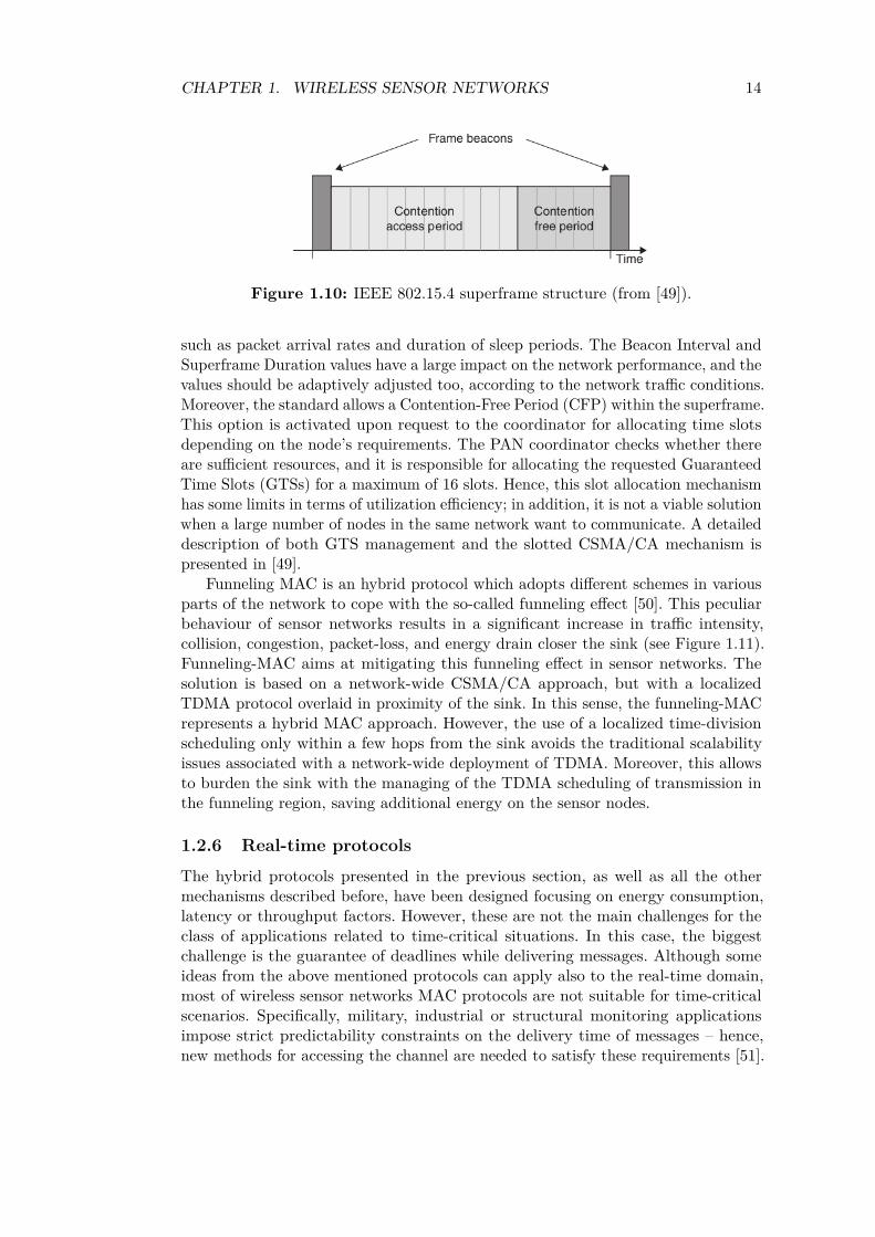
Funneling MAC is an hybrid protocol which adopts different schemes in variousparts of the network to cope with the so-called funneling effect [50]. This peculiarbehaviour of sensor networks results in a significant increase in traffic intensity,collision, congestion, packet-loss, and energy drain closer the sink (see Figure 1.11).Funneling-MAC aims at mitigating this funneling effect in sensor networks. Thesolution is based on a network-wide CSMA/CA approach, but with a localizedTDMA protocol overlaid in proximity of the sink. In this sense, the funneling-MACrepresents a hybrid MAC approach. However, the use of a localized time-divisionscheduling only within a few hops from the sink avoids the traditional scalabilityissues associated with a network-wide deployment of TDMA. Moreover, this allowsto burden the sink with the managing of the TDMA scheduling of transmission inthe funneling region, saving additional energy on the sensor nodes.
1.2.6 Real-time protocols
The hybrid protocols presented in the previous section, as well as all the othermechanisms described before, have been designed focusing on energy consumption,latency or throughput factors. However, these are not the main challenges for theclass of applications related to time-critical situations. In this case, the biggestchallenge is the guarantee of deadlines while delivering messages. Although someideas from the above mentioned protocols can apply also to the real-time domain,most of wireless sensor networks MAC protocols are not suitable for time-criticalscenarios. Specifically, military, industrial or structural monitoring applicationsimpose strict predictability constraints on the delivery time of messages – hence,new methods for accessing the channel are needed to satisfy these requirements [51].
CHAPTER 1. WIRELESS SENSOR NETWORKS 15
Figure 1.11: Funneling effect in WSN (from [50]).
Generally speaking, a real-time protocol should guarantee an upper bound forend-to-end delay of wireless transmissions. Real-time MAC-layer protocols can bedivided into two main classes, according to the way they consider time constraintswhile scheduling transmissions. A first class of mechanisms, sometimes addressed as“soft”, aims at minimizing the travel time of packets from each node of the network.These protocols calculate a schedule for the network and then derive an upper boundfor the transmissions’ delay.
For example, in [52] the issues related to energy consumption in sensor networksare addressed for varying spatio-temporal sampling rates of a physical phenomena.The authors propose a collision-free access protocol and investigate the tradeoffsbetween sensor density, energy consumption and spatial sampling rate. The paperalso investigates the relationship between delay and spatial sampling, given thesensors have always data to send.
A different algorithm for maximizing the lifetime of a sensor network whileguaranteeing an upper bound for the end-to-end delay is presented in [53]. Theauthors of this work include in the analysis both the information on the wake-upfrequency of a sensor and its location in a routing path, but they consider onlysporadic alarm-driven data transmissions.
The TIGRA (Timely Sensor Data Collection using Distributed Graph Coloring)protocol [54] ensures that no interference occurs and spatial channel reuse is max-imized by assigning a specific time slot for each node. TIGRA uses a distributedheuristic for graph colouring to guarantee a deterministic delay on sensor datacollection. The end-to-end delay incurred by sensor data collection largely dependson a specific topology, platform, and application, and TIGRA informs the applicationof the best possible delay it can provide.
RT-Link [55] is a protocol for industrial applications which provides reliablecollision-free operation and bounded end-to-end delay across multiple hops. Theprotocol requires a dedicated hardware for providing global time synchronizationwith an out-of-band mechanism. RT-Link schedules communications basing on thenetwork topology. This firstly requires a topology-gathering phase, followed by a
CHAPTER 1. WIRELESS SENSOR NETWORKS 16
scheduling phase. The gateway aggregates the list of neighbours from each node,and then constructs a connectivity graph and schedule nodes. Likewise the TIGRAprotocol, RT-Link generates a minimum delay schedule using an heuristic to solvethe distance-k node colouring problem.
The Low-power Real-Time Protocol (LPRT) [56] is a hybrid technique basedon dynamic TDMA and CSMA/CA. The protocol extends the GTS mechanism ofIEEE 802.15.4 defining a superframe, each consisting of 1024 mini-slots enclosed bytwo beacon messages. In the first part, the Contention Period allows the stations toassociate with the base station and to request mini-slots for transmissions during theContention Free Period (CFP). The CFP is composed of an optional retransmissionperiod (RP) and a normal transmission period (NTP). The RP is placed before theNTP to allow the retransmission of messages corrupted by channel errors before newdata are supposed to be transmitted.
BitMAC [57] builds a spanning tree rooted at the sink, where each node actsas an access point for its directly-connected children. Within each of these stars,time-division multiplexing is used to avoid interference between active children. Agraph-colouring algorithm is used to assign different channels to neighbouring stars,thus avoiding interferences. The nodes also exploit a bitwise “OR” of the heardtransmissions to distinguish data coming from multiple synchronized senders. Theprotocol provides deterministic bounds on the execution time of all its elements,while the total delay is not fixed – time slots are allocated on demand to nodes thatactually need to send data.
The TreeMAC protocol [58] works instead over ternary trees, and divides atime cycle into frames and each frame into slots. A parent node calculates thechildren’s frame assignment using their bandwidth demand, and each node findits own slot assignment using information about its hop-count to the sink. Thisscheduling algorithm provides a lower bound for data throughput to the gateway,and reduces buffering on intermediate nodes. However, every node uses a roundrobin method to assign frames to its children based on their proportional bandwidthdemand. This means that timeliness is guaranteed in presence of low-rate streams,while high channel demand can cause starvation for some nodes.
AREA-MAC [59] is a different protocol with which deals with time and energycritical applications, while maintaining reasonable system fairness. The mechanismcan be applied to grid topologies, where the density of nodes is high enough that anode can directly communicate with multiple neighbours. The idea is that targetnodes can adapt their duty cycles according to the requests of the sources. Thesimulation results show that AREA-MAC can maintain an acceptable system fairnessand trade-off between timeliness and energy efficiency.
For the sake of completeness, the literature analysis ends by considering [60]. Inthis paper, the authors work on a real-time scenario for applications where the datagathering must be performed within a specified latency constraint. However, thelatency constraints are derived from the routing paths of the considered network,and this value is then used to minimize energy consumption.
The problem with all the above real-time protocol is that a delay bound iscalculated assuming a specific network scenario, and there are no a-priori guaranteeddelays. Similarly, when new nodes enter the network or bandwidth requirementschanges, no admission control is performed. Instead, the new flows are always

CHAPTER 1. WIRELESS SENSOR NETWORKS 17
accepted and the protocols reschedule the transmissions aiming at providing fairness.To alleviate the problem, a second class of real-time protocol may be designed, oftenlabeled as “hard”. In this class of algorithm a maximum bandwidth requirement forsensors is used to validate the schedulability of a transmission, and new nodes canenter the network only if the deadlines of the other nodes are still satisfied.
Among examples of hard protocols we can list i-GAME [61], a new approach toIEEE 802.15.4 GTSs allocation which provides significant improvements in terms ofbandwidth utilization efficiency compared with the explicit allocation mechanism.The basic idea consists of sharing the same GTS among multiple nodes, instead ofstatically allocate it to a single node in all the superframes. With i-GAME, nodeswishing to enter the network, ask for a certain real-time service to the networkcoordinator. The admission control algorithm combines the bandwidth and delayrequirements of the new request with information on the available GTS resources.Then, the new allocation request is accepted if the algorithm finds a schedulewhich satisfies its requirements without affecting all those previously admitted. Theimplementation of i-GAME only requires minor add-ons to IEEE 802.15.4, but theproposed protocol is suitable only for flows with low rates and in single-hop networks.
Another hard real-time protocol is RRMAC [62], a TDMA mechanism for multi-hop networks. Sensors in a RRMAC network are organized in clusters, and clusterheads collect and aggregate data from the sensor nodes. Messages are then deliveredto the central node along a hierarchical tree structure. The protocol uses a basicsuperframe based on 802.15.4 to arrange transmissions from cluster heads to thegateway, and dedicated time slots for transmissions are assigned according to servicerequirements.
Channel Reuse-based Smallest Latest start time First (CR-SLF) [63] is a real-timecentralized scheduler which can provide timeliness guarantees for multi-hop messagetransmissions. The protocol uses an heuristic to arrange transmissions according toLatest transmission Start Time (LST) of messages, that is the time by which themessage must be scheduled to meet its end-to-end effective deadline constraints. Thebasic idea of the CR-SLF algorithm is to partition the set of packet transmissionsinto disjoint sets, such that communications in each set do not interfere with othersets and can be executed at the same time. Then, sets are ordered sequentially.
I-EDF (Implicit EDF) [64] is an adaptation of the classic real-time EarliestDeadline First scheduler to Wireless Sensor Network. The protocol is suitable forhard real-time applications, but it assumes a cellular network infrastructure andmulti-channel radios – thus, its applicability to traditional WSNs is limited.
Finally, Virtual TDMA for Sensors (VTS) [65] is a dynamic TDMA MAC protocol.VTS adaptively creates a TDMA arrangement with a number of timeslots equal tothe actual number of nodes in the range of the gateway. The duty cycle of sensornodes is increased or decreased in order to keep latency constant below a givendeadline. The main limit of the protocol is its applicability to single-hop networkonly.
In summary, many of the existing real-time protocols are suitable for soft ap-plication only. A few hard solutions for critical applications have been proposedtoo, but their applicability is limited to single-hop networks or applications withlimited bandwidth requirements. Looking at the big picture, there is still roomfor improvements, especially towards the design of solutions for multi-hop, high

CHAPTER 1. WIRELESS SENSOR NETWORKS 18
data-rates wireless sensor networks. Even more important, new real-time protocolsshould be able to guarantee a deterministic delay on transmissions taking intoaccount both the data acquisition frequency used to monitor the phenomena andthe validity deadlines of the acquired data.
1.3 Interconnecting Wireless Sensor NetworksBesides a number of small and energy constrained sensor nodes, a wireless sensornetwork usually includes one or more central nodes, also called gateways or sinks.These nodes are supposed to be less energy constrained, have more computationalpower and better storage capabilities. These features make these nodes suitable fornetwork management at different levels. For example, as described in the previoussection, some MAC protocols rely on a central node for computing the channelaccess scheduling, managing the transmissions within a cluster, or keeping the nodessynchronized through beacon signals. Other basic functions of gateways are querydistribution and data collections from the sensors. Finally, a gateway acts as a bridgebetween the sensor network and user applications, enabling the users to gatherinformation on the network from the outside [66, 67].
Different WSNs are based on different communication protocols, such as ZigBee[49], 6LoWPAN [68] or other proprietary technologies [69]. However, users anddevelopers are not interested in how the sensor nodes communicates – ideally, thegateway should hide the complexity of the WSN behind. Furthermore, the interfaceprovided by the gateway should be based on standard technologies and protocols tosimplify the interconnection to the Internet [70, 71].
The first real-world WSN which faced the problem of data access through Internetis represented by the Great Duck Island monitoring experiment – Mainwaring et al.deployed a network of 32 nodes on a small island to study seabird nesting habitatwhile streaming data onto the web [3]. Similarly, a fully-functioning sensor networkhas been deployed in a glacial environment to provide evaluations of global warming[72]. More recently, another solution for glacier monitoring has been developed anddeployed on the Alps by the Swiss EPFL institute of technology [4].
Integrating different objects is not a problem related to WSNs only, and it has beenalready faced by software engineers in the past. A possible solution is Service-OrientedArchitectures (SOA), a general style for building software applications based on theconcept of service. A service is an implementation of a well-defined functionality,and such services can be described, discovered, and invoked by heterogeneous clientsfrom anywhere, irrespectively of the network and the platforms used. The notion ofSOA can be easily mapped to the WSN domain, providing a service architecturefor modeling sensors as resources that can be discovered, queried, configured andmanaged remotely. For example, in [73] the authors introduced the concept of aSensor Network Common Interface for granting access to the sensors from any hostusing a service-oriented architecture. In this paper, the basis of the architecture iswell described: an example of a SOA for sensor networks is presented, with explicitcharacterization of three layers, from the sensor nodes to the host. Moreover, theauthors present the basics of an environmental monitoring system and how the datacoming from various WSNs should be exchanged and managed.
CHAPTER 1. WIRELESS SENSOR NETWORKS 19
Web services have taken the concept of Service Oriented technology and imple-mented it as services delivered over the Internet using Web-related technologies.This approach provides a transparent interaction through an interface accessiblefrom the Web. The interface of the service provider is formalized in a dedicatemachine-readable file called Web Services Description Language (WSDL). The othersystems interact with the Web service according to this description and using SOAPmessages, typically conveyed using HTTP with an XML serialization in conjunctionwith other Web-related standards [74].
As shown in [75], Web Services can be used as a foundation for communicatingwith sensors on one side, and exposing the processed data on the other end. More-over, publication and discovery mechanisms, together with security extensions, areexamples of additional features which can be enabled on a gateway based on thistechnology. The most notable system architecture for sensor network data collectionand fusion through the Web is probably SenseWeb [76]. This project, developedby Microsoft Research, is a unified system aiming to provide an open architectureto collect, share, process, and query sensory data provided by contributors acrossthe globe. This system provides an interactive tool to query sensors and visualizehistorical data through an open Web Service API.
The main criticism to traditional Web Services is that they are too complexand based upon large software vendors or integrators, rather than typical opensource implementations [77]. Moreover, they introduce considerable performancecosts related to the use of stateful connections, and the exchange and parsing oflarge XML files [78]. Recently, Representation State Transfer (REST) has emergedas a lightweight alternative to classic Web Services, since it does not require SOAPor WSDL definitions. This solution is not actually new: it relies on the samearchitectural and functioning principles of the World Wide Web. A REST-compliant(or “RESTful”) architecture focuses on the interaction with stateful resources, ratherthan messages or operations. The key idea is to describe the interface of a serviceusing a limited set of well-known, standard operations, such as GET, POST, PUT,DELETE for HTTP.
A first use of REST for WSNs is presented in [79], where a 6LoWPAN networkfor smart building has been provided with a RESTful programming interface forthe access to the resources. In the same work, all the data structures have beenrepresented using the JSON format, a lightweight text-based data interchange formatwhich is suitable as an XML alternative in bandwidth-constrained environments[80].
Another work regarding the application of RESTful interfaces in WSNs ispresented in [81]. The authors describ TinyREST, an architecture composed bywireless sensors or actuators which communicate wirelessly with a HTTP RESTfulgateway. Client terminals perform requests by querying the gateway, which interfacesthe network and the users. Guinard e Trifa in [82] present a similar architecture basedon a RESTful interaction between the sensor nodes of the WSN and a web-orientedsystem, where sensor nodes are viewed as RESTful resources. Using HTTP canonicalrequests to interact with sensor nodes, it is possible to obtain data mashups fromdifferent sensors located in different networks. Moreover, the visualization of themonitored parameters has been implemented using AJAX (Asynchronous JavaScriptand XML) web pages.
CHAPTER 1. WIRELESS SENSOR NETWORKS 20
The REST approach represents a viable solution for interfacing and commu-nicating with wireless sensor networks: it is lightweight, is based on reliable andwidespread standards, and can exchange data over stateless connections. Furtherinvestigations efforts could be put to formalize the way to expose the elements of asensor network using standard HTTP requests. Moreover, a REST interface can besmoothly integrated in an IP-based sensor network, while an appropriate translatorlayer must be run on the gateway to integrate other WSNs. In the latter case, theproblem of how to expose the acquired samples when they are stored in a structureddatabase has not yet been addressed.
1.4 Contribution of the ThesisAs mentioned above, the range of possible application fields for wireless sensornetworks is wide and extremely heterogeneous. As a consequence, it is becomingincreasingly difficult to discuss typical requirements regarding hardware and softwareelements without considering the context and the application field.
However, most of existing protocols have been validated through simulationsonly, and their performance on the field is still unknown. Moreover, the designof a protocol often starts from some initial assumptions which do not overlapthe actual requirements of the end user. In addition, most solutions are link andenvironment agnostic, ignoring the issues and peculiar characteristics of the nodesor the environment in which the wireless sensor network will operate.
This thesis aims at dealing with such issues, and presents new MAC protocolsfor environmental or structural monitoring which can provide some advantages withrespect to the existing solutions.
Second, the thesis proposes a cross-layer protocol for slow data reporting inenvironmental applications. This solution combines new ideas with features inspiredby existing protocols, and integrates the routing layer with the MAC mechanism ina flexible and energy-wise scheduled rendez-vous mechanism.
Finally, effective guidelines are provided for designing a novel interface for wirelesssensor networks based on standard protocols and a lightweight software architecturalstyle. A RESTful web service is designed in order to expose the data acquired fromone or more sensor networks using the HTTP protocol and the principles of REST.The resulting solution has been not only analyzed theoretically, but also tested inreal WSN implementations – a sample open-source implementation is described toprovide a reference starting point for further development. Specifically, the systemhas been used for presenting the result gathered by the sensor network for real-timemonitoring of structures and buildings described previously. In addition, the sameRESTful interface has been coupled with the second proposed protocol to assist incontinuous monitoring of environmental, slowly varying parameters.
The remainder of the thesis is therefore organized in three main chapters, followingthe three main research areas described above. Chapter 2 presents the features ofthe newly developed protocol for real-time acquisition, and shows the experimentalresults obtained from a realistic structural monitoring testbed. Then, Chapter 3describes the details of a cross-layer protocol for environmental monitoring and itsperformance when deployed on the field. Chapter 4 outlines the main features and theimplementation details of out RESTful interface for interfacing and managing either

CHAPTER 1. WIRELESS SENSOR NETWORKS 21
the environmental or structural monitoring systems. Finally, Chapter 5 concludes thethesis and suggests directions for the future research in the areas of MAC protocolsand interfaces for real-time wireless monitoring.

Chapter 2
PRISM, a novel real-time WSNMAC protocol for structuralmonitoring
2.1 IntroductionStructural monitoring is gaining momentum with the recent increasing interestin preservation of historical buildings, critical infrastructure monitoring, and inpost-earthquake damage detection. In these fields, Wireless Sensor Networks (WSNs)are a promising technology which could enable dense and distributed monitoring.Compared to other existing solutions, a WSN can significantly reduce the cost andthe time needed to setup a data acquisition system without the need for wires andcomplex hardware. However, Structural Health Monitoring (SHM) applications haveunique features, such as high-frequency sensing, strict clock synchronization andhigh data-rates. Moreover, critical measurements are often needed in near real-time –if data are received after a certain delay, they are not useful anymore.
As shown in Section 1.2, current WSNs are not suited for high-rate real-timeprocessing, as the majority of existing transmission and channel allocation protocolsare tailored to low sampling rates and loose latency constraints. Similarly, manydata processing algorithms are aimed at reducing the data-rate to save bandwidthand to reduce power consumption, against the need for timely transmissions, whichis a requirement of real-time monitoring applications.
The limited number of real-time protocols is reflected by the existing workingstructural monitoring systems, which start from the idea that acquisitions mustbe synchronous, but transmissions usually are not. Next section proposes a moredetailed analysis of current existing works for structural monitoring. Looking at thebig picture, latency is a fundamental scaling limitation for past researches: samplesare buffered by each node, and data are collected from every node one by one whenthe storage memory is filled up. Hence, the duration of a sampling test is usuallybounded by the amount of node memory to a maximum of a few hours. Moreover,data gathering takes a lot of time: in [83] and [84] the data collection phase for the
Partially published as: E. Goldoni and P. Gamba, “W-TREMORS, a Wireless MonitoringSystem for Earthquake Engineering,” IEEE EESMS Workshop 2010, pp. 50-56, Sep. 2010.
22
CHAPTER 2. REAL-TIME STRUCTURAL MONITORING 23
whole network takes about 6 times the duration of the sampling phase. A second issuewith these systems is their limited sampling bandwidth, which allows acquisitionfrequencies only below 100 Hz. Subsequently, these approaches are really valuablefor studying and preserving the long-term stability of buildings, but offer limitedvalidity for rapid structural damage response.
The solution proposed in this chapter is PRISM (Protocol for Real-tIme Syn-chronous Monitoring), a novel protocol for real-time and high data-rate synchronousacquisitions. This protocol can be implemented both in single-hop topologies andin multi-hop networks, whereas routing paths are logically organized on a binarytree. Unlike the standard 802.15.4 Medium Access Control, PRISM uses a deter-ministic temporal scheduling of transmissions. To be more precise, the protocoladaptively creates off-line a scheduling starting from the process sampling frequency;the scheduling of transmissions is then broadcast into the network before startingthe acquisition process.
The performance of the protocol has been studied theoretically, investigatingthe relationship among number of nodes, channel capacity and data-rate in bothsingle-hop and multi-hop networks. In addition, the protocol was implemented andtested in a low-cost, fully-functioning wireless monitoring system. The results confirmthe validity of PRISM, and the developed system is the first working WSN whichcan provide 1 KHz sampling rate and real-time data delivery using nodes which costless than 80 Euro each.
2.2 WSNs for Structural MonitoringRelated work on using WSNs for structural monitor includes notable experimentslike Wisden [7], Tenet [84] and the Golden Gate Bridge deployment [83]. Wisdenis a multi-hop wireless system for structural-response data acquisition designed atthe University of Southern California [7]. It incorporates a reliable multi-hop datatransport mechanism and a data time-stamping system which does not require globalsynchronization. A first implementation of the wireless network acquired data at50 Hz, and used a simple run-length encoding technique to detect and compressperiod of inactivity. The deployment experiences on a seismic test structure droveto a re-design of parts of the system [84]. In order to preserve the fidelity of thestructure’s frequency response, the sampling frequency was increased to 200 Hz,and an onset detection scheme was introduced during the compression phase. Thedelivery protocol of Wisden proved to be reliable and robust to data losses, achieving100% success in packet delivery during tests. However, latency is a fundamentalscaling limitation for this system: a continuous 1-minute shake requires about 6minutes to completely transmit corresponding data.
Similarly, Mechitov et al. [85] developed a wireless sensing system for structuralmonitoring based on Crossbow Technology Mica2 motes. Their implementation firststores sensor data in flash memories; then, values are delivered to the processingstation when the acquisition stops. Memory limitations on the sensor nodes allowedfor recording no more than 90 seconds of single-axes acceleration values of 250 KHzsampling frequency. Clock synchronization was also achieved adapting the FSTPtime synchronization service to the sensor network, ensuring proper synchronizationfor the target application.
CHAPTER 2. REAL-TIME STRUCTURAL MONITORING 24
The Golden Gate Bridge (GGB) deployment [83, 6] is one of the largest ex-perimental WSNs for structural monitoring. An integrated hardware and softwaresystem for a scalable SHM wireless network has been designed and implementedusing a dedicated accelerometer board, Mica-Z sensor nodes and the TinyOS oper-ating system. Additional software components have been implemented, includinga protocol for reliable command dissemination and data collection, and softwarefunctions for data pipelining, jitter control and high-frequency sampling. In theexperimental GGB deployment 64 nodes were distributed over the main span of thestructure, collecting vibrations synchronously over a 46-hop network. The nominalsampling was performed at 1 KHz, but the digitalized signal was downsampled to50 Hz by averaging. The network layer of this system is able to reliably delivermeasurements to the central station, although data gathering from the networkis performed off-line: about 250,000 samples are buffered by each node, and whenthe storage memory is filled up data are collected from every node one by one. Acomplete cycle of sampling and data collection for the full network would take about9-12 hours [83].
Finally, two additional recent experiments have been presented in [86, 87]. Inthe first work [86], researchers used low-cost hardware to developed a WSN forreal-time SHM. The resulting sensor network supports real-time acquisition fromup to 20 wireless units with negligible data losses; however the bandwidth of thefinal estimation is limited below 128 Hz. In the second work, a fully-working customsystem has been deployed in Torre Aquila, a medieval tower in Trento, Italy. Basingon 4 months of operation, the authors showed the effectiveness of the designedWSN for assessing the tower’s stability, as it proved to deliver data with loss ratios< 0.01% and an estimated lifetime beyond one year [87].
Despite a number of notable efforts, it is clear that there is room for improvementsin the design of a cheap and real-time wireless sensing systems. Specifically, thereis a clear need for a MAC and data delivery protocol able to support distributed,time-synchronized acquisitions with over-100 Hz sampling frequencies. This protocolshould also enable real-time and reliable data delivery, eliminating collisions amongtransmissions and providing guarantees on timeliness.
2.3 An Overview of the PRISM ProtocolThe newly proposed PRISM protocol is specifically tailored for high data-rateand real-time WSNs. This protocol overcomes the above mentioned limitations ofcurrently available sensor networks using a TDMA-like channel access mechanismand organizing transmissions in an efficient way. Furthermore, the approach employsa simple in-band synchronization mechanism which does not require dedicatedhardware, avoiding to tie the protocol to a specific platform. The protocol canbe implemented both in single-hop topologies and in multi-hop networks, whereasrouting paths are logically organized on a perfect binary tree. The remainder of thissection describes these main features of PRISM in detail.
CHAPTER 2. REAL-TIME STRUCTURAL MONITORING 25
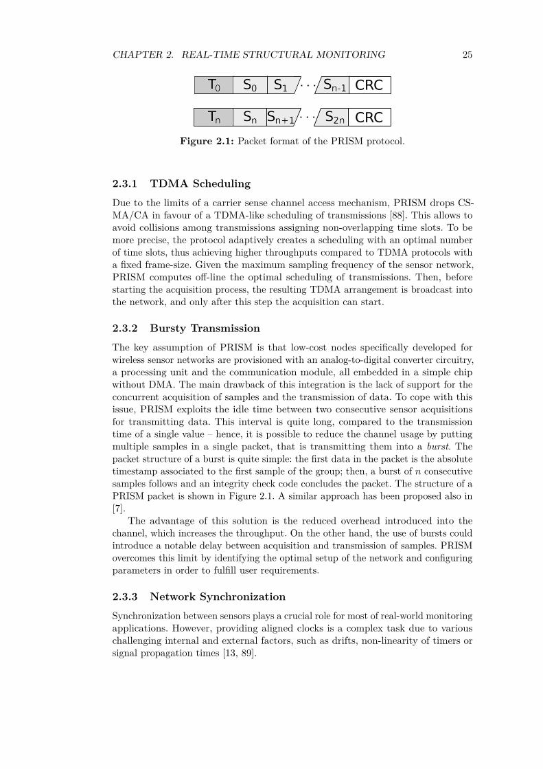
T0 S0 S1 Sn-1 CRC
Tn Sn Sn+1 S2n CRC
Figure 2.1: Packet format of the PRISM protocol.
2.3.1 TDMA Scheduling
Due to the limits of a carrier sense channel access mechanism, PRISM drops CS-MA/CA in favour of a TDMA-like scheduling of transmissions [88]. This allows toavoid collisions among transmissions assigning non-overlapping time slots. To bemore precise, the protocol adaptively creates a scheduling with an optimal numberof time slots, thus achieving higher throughputs compared to TDMA protocols witha fixed frame-size. Given the maximum sampling frequency of the sensor network,PRISM computes off-line the optimal scheduling of transmissions. Then, beforestarting the acquisition process, the resulting TDMA arrangement is broadcast intothe network, and only after this step the acquisition can start.
2.3.2 Bursty Transmission
The key assumption of PRISM is that low-cost nodes specifically developed forwireless sensor networks are provisioned with an analog-to-digital converter circuitry,a processing unit and the communication module, all embedded in a simple chipwithout DMA. The main drawback of this integration is the lack of support for theconcurrent acquisition of samples and the transmission of data. To cope with thisissue, PRISM exploits the idle time between two consecutive sensor acquisitionsfor transmitting data. This interval is quite long, compared to the transmissiontime of a single value – hence, it is possible to reduce the channel usage by puttingmultiple samples in a single packet, that is transmitting them into a burst. Thepacket structure of a burst is quite simple: the first data in the packet is the absolutetimestamp associated to the first sample of the group; then, a burst of 𝑛 consecutivesamples follows and an integrity check code concludes the packet. The structure of aPRISM packet is shown in Figure 2.1. A similar approach has been proposed also in[7].
The advantage of this solution is the reduced overhead introduced into thechannel, which increases the throughput. On the other hand, the use of bursts couldintroduce a notable delay between acquisition and transmission of samples. PRISMovercomes this limit by identifying the optimal setup of the network and configuringparameters in order to fulfill user requirements.
2.3.3 Network Synchronization
Synchronization between sensors plays a crucial role for most of real-world monitoringapplications. However, providing aligned clocks is a complex task due to variouschallenging internal and external factors, such as drifts, non-linearity of timers orsignal propagation times [13, 89].

CHAPTER 2. REAL-TIME STRUCTURAL MONITORING 26
PRISM adopts a flexible, in-band approach to keep nodes synchronized. Insingle-hop networks, the gateway periodically broadcasts a clock signal to all thesensor nodes during a dedicated time slot. On the other hand, in larger networksother existing distributed synchronization algorithms can be used during one ormore dedicated time slots.
The details of the various synchronization solutions which can be implemented instar and multi-hop topologies are better described in the following sections, devotedto single-hop and multi-hop networks respectively.
2.4 PRISM in Single-Hop NetworksThe considered single-hop network is organized into a simple star topology coordi-nated by a central gateway. This device is responsible for the initial configuration ofthe network, the scheduling of transmissions and the collection of all the measure-ments acquired by sensors. Therefore, the gateway is supposed to be less energy andcomputationally constrained than the other nodes of the network.
2.4.1 Theoretical Analysis
We know that the transmission of data and the acquisition of samples at a givenfrequency 𝑓𝑠 are mutually exclusive. Therefore, the duration 𝑇𝑠𝑙𝑜𝑡 of the time slotassigned to a node can not exceed the interval between two consecutive acquisitions:
1𝑓𝑠≥ 𝑇𝑠𝑙𝑜𝑡 (2.1)
and the transmission of the burst (𝑇𝑏𝑢𝑟𝑠𝑡) must fit inside the time slot:
𝑇𝑠𝑙𝑜𝑡 ≥ 𝑇𝑏𝑢𝑟𝑠𝑡. (2.2)
Combining (2.1) and (2.2) we get:
1𝑓𝑠≥ 𝑇𝑏𝑢𝑟𝑠𝑡 = 𝑃𝑏𝑢𝑟𝑠𝑡(𝑆)
𝐶, (2.3)
where 𝑃𝑏𝑢𝑟𝑠𝑡(𝑆) is the size of the burst data unit sent by the node and 𝐶 the channelcapacity. Since a burst contains 𝑆 sample of size 𝑃𝑠𝑎𝑚𝑝𝑙𝑒 and an optional header of𝑃ℎ𝑒𝑎𝑑𝑒𝑟 byte, we have:
𝑃𝑏𝑢𝑟𝑠𝑡(𝑆) = 𝑆 · 𝑃𝑠𝑎𝑚𝑝𝑙𝑒 + 𝑃ℎ𝑒𝑎𝑑𝑒𝑟 (2.4)
and we can rewrite (2.3) as
1𝑓𝑠≥ 𝑆 · 𝑃𝑠𝑎𝑚𝑝𝑙𝑒 + 𝑃ℎ𝑒𝑎𝑑𝑒𝑟
𝐶(2.5)
According to (2.5), the maximum number of samples in a single data unit sent byPRISM may be:
𝑆𝑚𝑎𝑥 =⌊︃
1𝑃𝑠𝑎𝑚𝑝𝑙𝑒
·(︂
𝐶
𝑓𝑠− 𝑃ℎ𝑒𝑎𝑑𝑒𝑟
)︂⌋︃(2.6)
CHAPTER 2. REAL-TIME STRUCTURAL MONITORING 27
Since a burst is made of 𝑆 samples acquired at frequency 𝑓𝑠, a node will senddata to the gateway every 𝐻 seconds, where
𝐻 = 𝑆 · 1𝑓𝑠
(2.7)
This periodic transmission must be performed by all nodes in the wireless sensornetwork: during this interval each node must transmit at least once. Hence, 𝐻 canbe considered the hyper-period of the transmission cycle in a PRISM network.
Therefore, the maximum number 𝑁 of devices in the network when using a slotper node per hyper-period can be calculated as:
𝑁 = 𝐻
𝑇𝑠𝑙𝑜𝑡=
𝑆𝑚𝑎𝑥 · 1𝑓𝑠
𝑇𝑠𝑙𝑜𝑡≤
𝑆𝑚𝑎𝑥 · 1𝑓𝑠
𝑓𝑠= 𝑆𝑚𝑎𝑥 (2.8)
Hence, if we put in a burst the maximum allowed number of samples 𝑆𝑚𝑎𝑥,acquired at a given frequency 𝑓𝑠, the biggest network we can build is made up of𝑁𝑚𝑎𝑥 = 𝑆𝑚𝑎𝑥 nodes.
Finally, since measurements are sent periodically by the nodes after an hyper-period, the maximum delay 𝐷 experienced by values is
𝐷 = 𝐻. (2.9)
2.4.2 Synchronization issues
As foreshadowed in Section 2.3, PRISM adopts a centralized in-band synchronizationmechanism in order to compensate clock discrepancy among sensor nodes withoutrequiring dedicated hardware. In a star topology, either a reference node or thegateway itself periodically broadcasts a clock signal to all the sensor nodes during adedicated time slot. Given the reference node sends the a message every hyper-period,the remaining 𝑁 − 1 slots remain free. Hence, the actual maximum number of nodesin a WSN based on PRISM is reduced to 𝑁−1. Moreover, the maximum length 𝑇𝑠𝑦𝑛𝑐
of the synchronization signal is equal to 𝑇𝑠𝑙𝑜𝑡 while the re-synchronization frequencyis 𝐻. However, should the specific mechanism take longer to calibrate all clocks,𝑋 consecutive time slots could be used for this tasks, leaving 𝑁 −𝑋 intervals freefor sensor nodes. Similarly, various non-consecutive slots in the same hyper-periodcould be used instead to repeat the process, hence increasing the synchronizationfrequency without affecting the sensor sampling period.
This solution features low execution time, low traffic overhead, and it also providesaccurate synchronization for most practical uses. Nevertheless, the approach is flexibleand it could be easily extended using other well-established algorithms during thededicated time slot in place of a single reference signal, such as [89, 90] or [91].
2.5 PRISM in Multi-hop NetworksIt is possile to extended PRISM from the single-hop case to multi-hop networkslogically organized as a binary tree. This is not an oversimplifying hypothesis: manyrouting protocols designed for the WSN domain calculate network paths so thattransmissions are routed and forwarded along such a hierarchical topology (see, forinstance, [38, 92]).
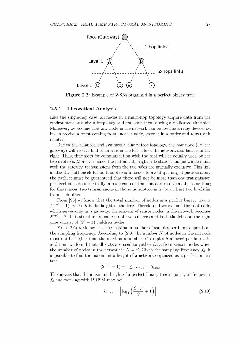
CHAPTER 2. REAL-TIME STRUCTURAL MONITORING 28
Figure 2.2: Example of WSNs organized in a perfect binary tree.
2.5.1 Theoretical Analysis
Like the single-hop case, all nodes in a multi-hop topology acquire data from theenvironment at a given frequency and transmit them during a dedicated time slot.Moreover, we assume that any node in the network can be used as a relay device, i.e.it can receive a burst coming from another node, store it in a buffer and retransmitit later.
Due to the balanced and symmetric binary tree topology, the root node (i.e. thegateway) will receive half of data from the left side of the network and half from theright. Thus, time slots for communication with the root will be equally used by thetwo subtrees. Moreover, since the left and the right side share a unique wireless linkwith the gateway, transmissions from the two sides are mutually exclusive. This linkis also the bottleneck for both subtrees: in order to avoid queuing of packets alongthe path, it must be guaranteed that there will not be more than one transmissionper level in each side. Finally, a node can not transmit and receive at the same time;for this reason, two transmissions in the same subtree must be at least two levels farfrom each other.
From [93] we know that the total number of nodes in a perfect binary tree is(2ℎ+1 − 1), where ℎ is the height of the tree. Therefore, if we exclude the root node,which serves only as a gateway, the amount of sensor nodes in the network becomes2ℎ+1 − 2. This structure is made up of two subtrees and both the left and the rightones consist of (2ℎ − 1) children nodes.
From (2.6) we know that the maximum number of samples per burst depends onthe sampling frequency. According to (2.8) the number 𝑁 of nodes in the networkmust not be higher than the maximum number of samples 𝑆 allowed per burst. Inaddition, we found that all slots are used to gather data from sensor nodes whenthe number of nodes in the network is 𝑁 = 𝑆. Given the sampling frequency 𝑓𝑠, itis possible to find the maximum ℎ height of a network organized as a perfect binarytree:
(2ℎ+1 − 1)− 1 ≤ 𝑁𝑚𝑎𝑥 = 𝑆𝑚𝑎𝑥
This means that the maximum height of a perfect binary tree acquiring at frequency𝑓𝑠 and working with PRISM may be:
ℎ𝑚𝑎𝑥 =⌊︂log2
(︂𝑆𝑚𝑎𝑥
2 + 1)︂⌋︂
(2.10)
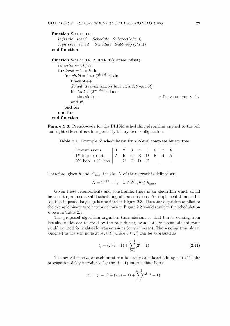
CHAPTER 2. REAL-TIME STRUCTURAL MONITORING 29
function Scheduler𝑙𝑒𝑓𝑡𝑠𝑖𝑑𝑒_𝑠𝑐ℎ𝑒𝑑 = 𝑆𝑐ℎ𝑒𝑑𝑢𝑙𝑒_𝑆𝑢𝑏𝑡𝑟𝑒𝑒(𝑙𝑒𝑓𝑡, 0)𝑟𝑖𝑔ℎ𝑡𝑠𝑖𝑑𝑒_𝑠𝑐ℎ𝑒𝑑 = 𝑆𝑐ℎ𝑒𝑑𝑢𝑙𝑒_𝑆𝑢𝑏𝑡𝑟𝑒𝑒(𝑟𝑖𝑔ℎ𝑡, 1)
end function
function Schedule_Subtree(subtree, offset)𝑡𝑖𝑚𝑒𝑠𝑙𝑜𝑡← 𝑜𝑓𝑓𝑠𝑒𝑡for 𝑙𝑒𝑣𝑒𝑙 = 1 to ℎ do
for 𝑐ℎ𝑖𝑙𝑑 = 1 to (2𝑙𝑒𝑣𝑒𝑙−1) dotimeslot++𝑆𝑐ℎ𝑒𝑑_𝑇𝑟𝑎𝑛𝑠𝑚𝑖𝑠𝑠𝑖𝑜𝑛(𝑙𝑒𝑣𝑒𝑙, 𝑐ℎ𝑖𝑙𝑑, 𝑡𝑖𝑚𝑒𝑠𝑙𝑜𝑡)if 𝑐ℎ𝑖𝑙𝑑 ̸= (2𝑙𝑒𝑣𝑒𝑙−1) then
timeslot++ ◁ Leave an empty slotend if
end forend for
end function
Figure 2.3: Pseudo-code for the PRISM scheduling algorithm applied to the leftand right-side subtrees in a perfectly binary tree configuration.
Table 2.1: Example of schedulation for a 2-level complete binary tree
Transmissions 1 2 3 4 5 6 7 81𝑠𝑡 hop → root A B C E D F A B2𝑛𝑑 hop → 1𝑠𝑡 hop C E D F ..
Therefore, given ℎ and 𝑆𝑚𝑎𝑥, the size 𝑁 of the network is defined as:
𝑁 = 2ℎ+1 − 1, ℎ ∈ 𝑁+, ℎ ≤ ℎ𝑚𝑎𝑥
Given these requirements and constraints, there is an algorithm which couldbe used to produce a valid scheduling of transmissions. An implementation of thissolution in psudo-language is described in Figure 2.3. The same algorithm applied tothe example binary tree network shown in Figure 2.2 would result in the schedulationshown in Table 2.1.
The proposed algorithm organizes transmissions so that bursts coming fromleft-side nodes are received by the root during even slots, whereas odd intervalswould be used for right-side transmissions (or vice versa). The sending time slot 𝑡𝑖
assigned to the 𝑖-th node at level 𝑙 (where 𝑖 ≤ 2𝑙) can be expressed as
𝑡𝑖 = (2 · 𝑖− 1) +𝑥−1∑︁𝑙=1
(2𝑙 − 1) (2.11)
The arrival time 𝑎𝑖 of each burst can be easily calculated adding to (2.11) thepropagation delay introduced by the (𝑙 − 1) intermediate hops:
𝑎𝑖 = (𝑙 − 1) + (2 · 𝑖− 1) +𝑥−1∑︁𝑙=1
(2𝑙−1 − 1)

CHAPTER 2. REAL-TIME STRUCTURAL MONITORING 30
which can be rewritten as:
𝑎𝑖 = (2 · 𝑖− 2) + 𝑙 +𝑥−1∑︁𝑙=1
(2𝑙 − 1) (2.12)
According to this equation, 𝑎𝑖 will always be odd: hence, the arrival time of burst onthe root node would always coincide with odd time slots. Moreover, the empty slotbetween two burst guarantees that there will never be a two consecutive levels onthe same side. In addition, such a scheduling for the left or right subtree is able tofill exactly half of the slots. Finally, the arrival time of the last child 𝑐 at the deepestlevel ℎ of the tree is:
𝑎𝑐 = (ℎ− 1) +ℎ∑︁
𝑙=1(2𝑙 − 1)
This results can be also rewritten using the properties of geometric series as:
𝑎𝑐 = (2ℎ+1 − 2)− 1
But we also know that the total number 𝑁 of sensor nodes in the tree is 2ℎ+1 − 2.Combining the two equations above, we can calculate that the last time slot used todeliver data acquired by the nodes in one subtree is the (𝑁 − 1)th.
The same algorithm described in Figure 2.3 applies also to the right-side, sincethe two subtrees are symmetric. Hence, a phase displacement by one slot wouldresult in transmissions to the root node only during even slots. Therefore, the rootnode will never experience collisions: odd slots unused by one subtree would beused by the other and vice versa. Moreover, this scheduling is able to fill all the 𝑁time slots of an hyper-period: 𝑁/2 acquired from the sensors of one subtree and theremaining 𝑁/2 from the other subtree. Hence, the hyper-period H is composed of2 · 𝑁
2 = 𝑁 = 𝑆 slots and we have:
𝐻 = 𝑆 · 1𝑓𝑠
= 𝑁 · 1𝑓𝑠
(2.13)
which is exactly the result for the single-hop case in (2.7).There is however a change in the maximum delay experienced by data in a burst,
since the effects introduced by intermediate nodes should be considered, too. Thefirst sample in a burst must wait 𝐻 time slot before being sent; then, it may have tocross one or more intermediate hops before arriving to the root node. Hence, themaximum delay experienced by data from a level-𝑙 node will be
𝐷 = 𝐻 + (𝑙 − 1) (2.14)
It is interesting to note that, like in (2.9) for the single-hop case, the delay fornodes directly connected to the gateway is exactly 𝐷 = 𝐻 . This is reasonable, sincea star network with two sensor device is also a binary tree with level-1 nodes only.
2.5.2 Synchronization issues
Node synchronization in a multi-hop network based on PRISM can be achievedusing different approaches. The most straightforward is that of a reference node
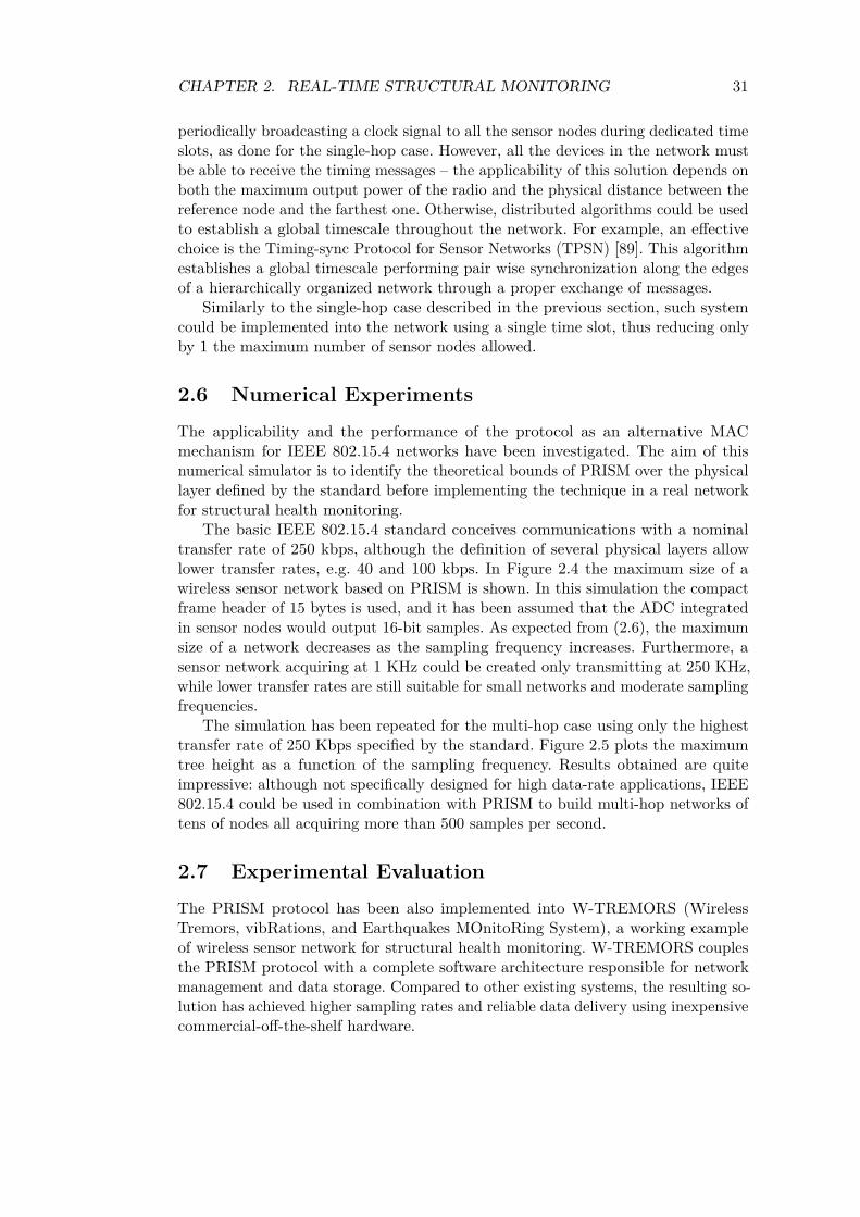
CHAPTER 2. REAL-TIME STRUCTURAL MONITORING 31
periodically broadcasting a clock signal to all the sensor nodes during dedicated timeslots, as done for the single-hop case. However, all the devices in the network mustbe able to receive the timing messages – the applicability of this solution depends onboth the maximum output power of the radio and the physical distance between thereference node and the farthest one. Otherwise, distributed algorithms could be usedto establish a global timescale throughout the network. For example, an effectivechoice is the Timing-sync Protocol for Sensor Networks (TPSN) [89]. This algorithmestablishes a global timescale performing pair wise synchronization along the edgesof a hierarchically organized network through a proper exchange of messages.
Similarly to the single-hop case described in the previous section, such systemcould be implemented into the network using a single time slot, thus reducing onlyby 1 the maximum number of sensor nodes allowed.
2.6 Numerical ExperimentsThe applicability and the performance of the protocol as an alternative MACmechanism for IEEE 802.15.4 networks have been investigated. The aim of thisnumerical simulator is to identify the theoretical bounds of PRISM over the physicallayer defined by the standard before implementing the technique in a real networkfor structural health monitoring.
The basic IEEE 802.15.4 standard conceives communications with a nominaltransfer rate of 250 kbps, although the definition of several physical layers allowlower transfer rates, e.g. 40 and 100 kbps. In Figure 2.4 the maximum size of awireless sensor network based on PRISM is shown. In this simulation the compactframe header of 15 bytes is used, and it has been assumed that the ADC integratedin sensor nodes would output 16-bit samples. As expected from (2.6), the maximumsize of a network decreases as the sampling frequency increases. Furthermore, asensor network acquiring at 1 KHz could be created only transmitting at 250 KHz,while lower transfer rates are still suitable for small networks and moderate samplingfrequencies.
The simulation has been repeated for the multi-hop case using only the highesttransfer rate of 250 Kbps specified by the standard. Figure 2.5 plots the maximumtree height as a function of the sampling frequency. Results obtained are quiteimpressive: although not specifically designed for high data-rate applications, IEEE802.15.4 could be used in combination with PRISM to build multi-hop networks oftens of nodes all acquiring more than 500 samples per second.
2.7 Experimental EvaluationThe PRISM protocol has been also implemented into W-TREMORS (WirelessTremors, vibRations, and Earthquakes MOnitoRing System), a working exampleof wireless sensor network for structural health monitoring. W-TREMORS couplesthe PRISM protocol with a complete software architecture responsible for networkmanagement and data storage. Compared to other existing systems, the resulting so-lution has achieved higher sampling rates and reliable data delivery using inexpensivecommercial-off-the-shelf hardware.
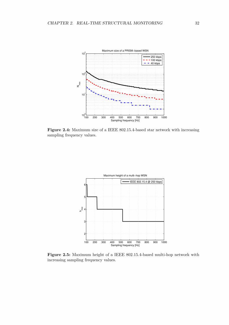
CHAPTER 2. REAL-TIME STRUCTURAL MONITORING 32
100 200 300 400 500 600 700 800 900 100010
0
101
102
103
Sampling frequency [Hz]
Nm
ax
Maximum size of a PRISM−based WSN
250 kbps
100 kbps
40 kbps
Figure 2.4: Maximum size of a IEEE 802.15.4-based star network with increasingsampling frequency values.
100 200 300 400 500 600 700 800 900 1000
2
3
4
5
6
Sampling frequency [Hz]
hm
ax
Maximum height of a multi−hop WSN
IEEE 802.15.4 @ 250 kbps
Figure 2.5: Maximum height of a IEEE 802.15.4-based multi-hop network withincreasing sampling frequency values.
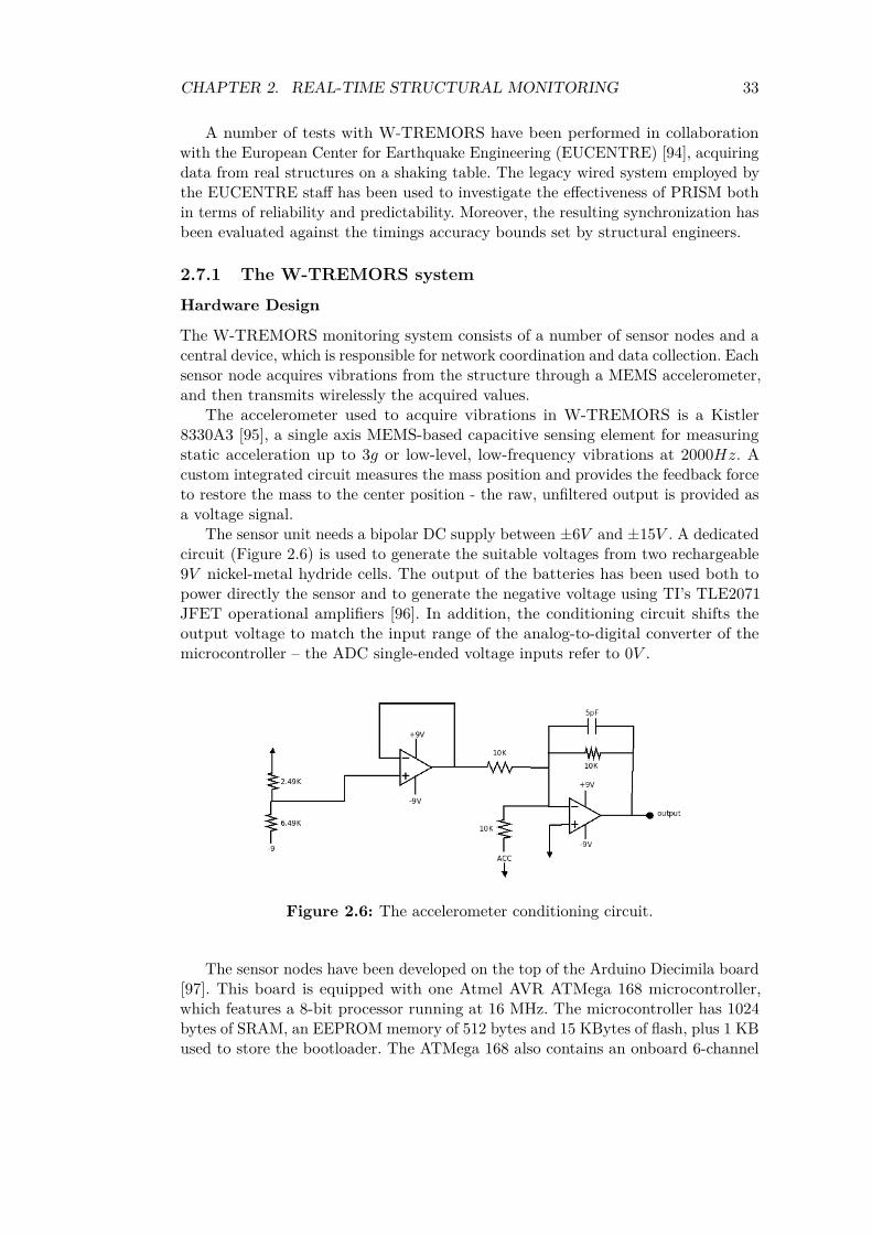
CHAPTER 2. REAL-TIME STRUCTURAL MONITORING 33
A number of tests with W-TREMORS have been performed in collaborationwith the European Center for Earthquake Engineering (EUCENTRE) [94], acquiringdata from real structures on a shaking table. The legacy wired system employed bythe EUCENTRE staff has been used to investigate the effectiveness of PRISM bothin terms of reliability and predictability. Moreover, the resulting synchronization hasbeen evaluated against the timings accuracy bounds set by structural engineers.
2.7.1 The W-TREMORS system
Hardware Design
The W-TREMORS monitoring system consists of a number of sensor nodes and acentral device, which is responsible for network coordination and data collection. Eachsensor node acquires vibrations from the structure through a MEMS accelerometer,and then transmits wirelessly the acquired values.
The accelerometer used to acquire vibrations in W-TREMORS is a Kistler8330A3 [95], a single axis MEMS-based capacitive sensing element for measuringstatic acceleration up to 3𝑔 or low-level, low-frequency vibrations at 2000𝐻𝑧. Acustom integrated circuit measures the mass position and provides the feedback forceto restore the mass to the center position - the raw, unfiltered output is provided asa voltage signal.
The sensor unit needs a bipolar DC supply between ±6𝑉 and ±15𝑉 . A dedicatedcircuit (Figure 2.6) is used to generate the suitable voltages from two rechargeable9𝑉 nickel-metal hydride cells. The output of the batteries has been used both topower directly the sensor and to generate the negative voltage using TI’s TLE2071JFET operational amplifiers [96]. In addition, the conditioning circuit shifts theoutput voltage to match the input range of the analog-to-digital converter of themicrocontroller – the ADC single-ended voltage inputs refer to 0𝑉 .
Figure 2.6: The accelerometer conditioning circuit.
The sensor nodes have been developed on the top of the Arduino Diecimila board[97]. This board is equipped with one Atmel AVR ATMega 168 microcontroller,which features a 8-bit processor running at 16 MHz. The microcontroller has 1024bytes of SRAM, an EEPROM memory of 512 bytes and 15 KBytes of flash, plus 1 KBused to store the bootloader. The ATMega 168 also contains an onboard 6-channel
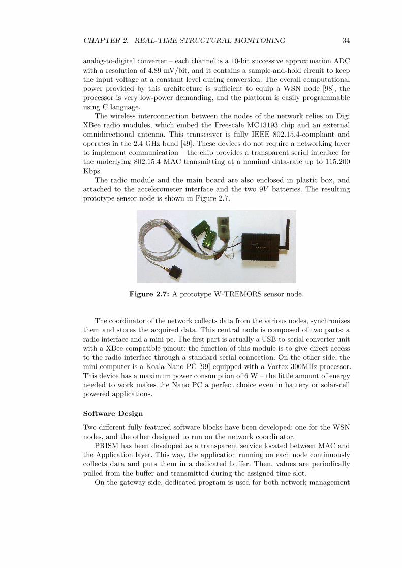
CHAPTER 2. REAL-TIME STRUCTURAL MONITORING 34
analog-to-digital converter – each channel is a 10-bit successive approximation ADCwith a resolution of 4.89 mV/bit, and it contains a sample-and-hold circuit to keepthe input voltage at a constant level during conversion. The overall computationalpower provided by this architecture is sufficient to equip a WSN node [98], theprocessor is very low-power demanding, and the platform is easily programmableusing C language.
The wireless interconnection between the nodes of the network relies on DigiXBee radio modules, which embed the Freescale MC13193 chip and an externalomnidirectional antenna. This transceiver is fully IEEE 802.15.4-compliant andoperates in the 2.4 GHz band [49]. These devices do not require a networking layerto implement communication – the chip provides a transparent serial interface forthe underlying 802.15.4 MAC transmitting at a nominal data-rate up to 115.200Kbps.
The radio module and the main board are also enclosed in plastic box, andattached to the accelerometer interface and the two 9𝑉 batteries. The resultingprototype sensor node is shown in Figure 2.7.
Figure 2.7: A prototype W-TREMORS sensor node.
The coordinator of the network collects data from the various nodes, synchronizesthem and stores the acquired data. This central node is composed of two parts: aradio interface and a mini-pc. The first part is actually a USB-to-serial converter unitwith a XBee-compatible pinout: the function of this module is to give direct accessto the radio interface through a standard serial connection. On the other side, themini computer is a Koala Nano PC [99] equipped with a Vortex 300MHz processor.This device has a maximum power consumption of 6 W – the little amount of energyneeded to work makes the Nano PC a perfect choice even in battery or solar-cellpowered applications.
Software Design
Two different fully-featured software blocks have been developed: one for the WSNnodes, and the other designed to run on the network coordinator.
PRISM has been developed as a transparent service located between MAC andthe Application layer. This way, the application running on each node continuouslycollects data and puts them in a dedicated buffer. Then, values are periodicallypulled from the buffer and transmitted during the assigned time slot.
On the gateway side, dedicated program is used for both network management
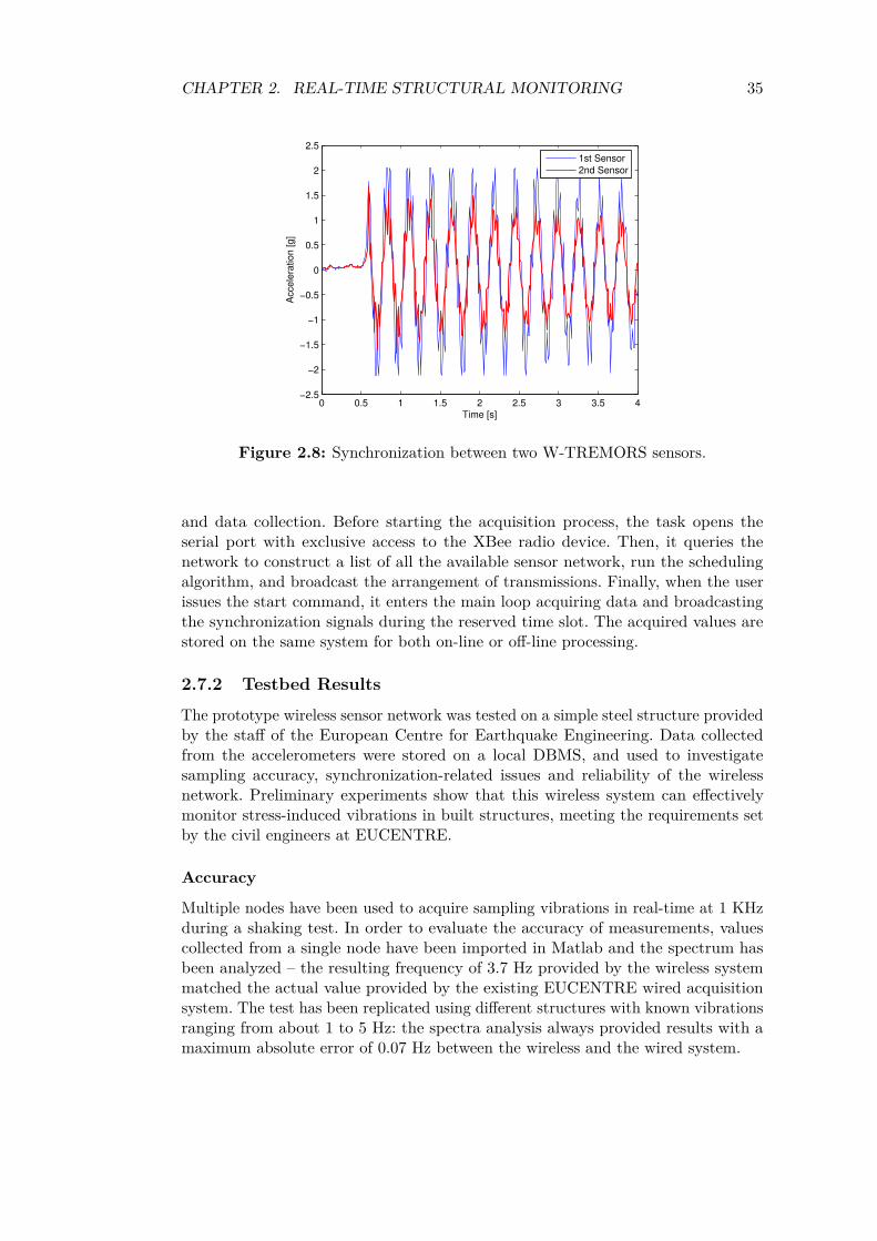
CHAPTER 2. REAL-TIME STRUCTURAL MONITORING 35
0 0.5 1 1.5 2 2.5 3 3.5 4−2.5
−2
−1.5
−1
−0.5
0
0.5
1
1.5
2
2.5
Time [s]
Acce
lera
tio
n [
g]
1st Sensor
2nd Sensor
Figure 2.8: Synchronization between two W-TREMORS sensors.
and data collection. Before starting the acquisition process, the task opens theserial port with exclusive access to the XBee radio device. Then, it queries thenetwork to construct a list of all the available sensor network, run the schedulingalgorithm, and broadcast the arrangement of transmissions. Finally, when the userissues the start command, it enters the main loop acquiring data and broadcastingthe synchronization signals during the reserved time slot. The acquired values arestored on the same system for both on-line or off-line processing.
2.7.2 Testbed Results
The prototype wireless sensor network was tested on a simple steel structure providedby the staff of the European Centre for Earthquake Engineering. Data collectedfrom the accelerometers were stored on a local DBMS, and used to investigatesampling accuracy, synchronization-related issues and reliability of the wirelessnetwork. Preliminary experiments show that this wireless system can effectivelymonitor stress-induced vibrations in built structures, meeting the requirements setby the civil engineers at EUCENTRE.
Accuracy
Multiple nodes have been used to acquire sampling vibrations in real-time at 1 KHzduring a shaking test. In order to evaluate the accuracy of measurements, valuescollected from a single node have been imported in Matlab and the spectrum hasbeen analyzed – the resulting frequency of 3.7 Hz provided by the wireless systemmatched the actual value provided by the existing EUCENTRE wired acquisitionsystem. The test has been replicated using different structures with known vibrationsranging from about 1 to 5 Hz: the spectra analysis always provided results with amaximum absolute error of 0.07 Hz between the wireless and the wired system.
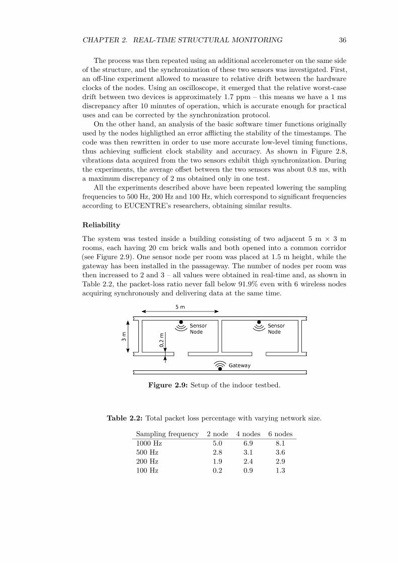
CHAPTER 2. REAL-TIME STRUCTURAL MONITORING 36
The process was then repeated using an additional accelerometer on the same sideof the structure, and the synchronization of these two sensors was investigated. First,an off-line experiment allowed to measure to relative drift between the hardwareclocks of the nodes. Using an oscilloscope, it emerged that the relative worst-casedrift between two devices is approximately 1.7 ppm – this means we have a 1 msdiscrepancy after 10 minutes of operation, which is accurate enough for practicaluses and can be corrected by the synchronization protocol.
On the other hand, an analysis of the basic software timer functions originallyused by the nodes highligthed an error afflicting the stability of the timestamps. Thecode was then rewritten in order to use more accurate low-level timing functions,thus achieving sufficient clock stability and accuracy. As shown in Figure 2.8,vibrations data acquired from the two sensors exhibit thigh synchronization. Duringthe experiments, the average offset between the two sensors was about 0.8 ms, witha maximum discrepancy of 2 ms obtained only in one test.
All the experiments described above have been repeated lowering the samplingfrequencies to 500 Hz, 200 Hz and 100 Hz, which correspond to significant frequenciesaccording to EUCENTRE’s researchers, obtaining similar results.
Reliability
The system was tested inside a building consisting of two adjacent 5 m × 3 mrooms, each having 20 cm brick walls and both opened into a common corridor(see Figure 2.9). One sensor node per room was placed at 1.5 m height, while thegateway has been installed in the passageway. The number of nodes per room wasthen increased to 2 and 3 – all values were obtained in real-time and, as shown inTable 2.2, the packet-loss ratio never fall below 91.9% even with 6 wireless nodesacquiring synchronously and delivering data at the same time.
Figure 2.9: Setup of the indoor testbed.
Table 2.2: Total packet loss percentage with varying network size.
Sampling frequency 2 node 4 nodes 6 nodes1000 Hz 5.0 6.9 8.1500 Hz 2.8 3.1 3.6200 Hz 1.9 2.4 2.9100 Hz 0.2 0.9 1.3
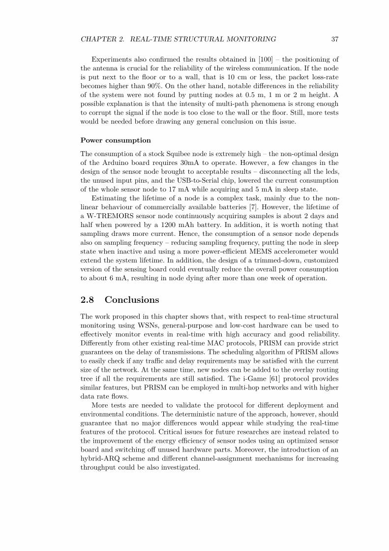
CHAPTER 2. REAL-TIME STRUCTURAL MONITORING 37
Experiments also confirmed the results obtained in [100] – the positioning ofthe antenna is crucial for the reliability of the wireless communication. If the nodeis put next to the floor or to a wall, that is 10 cm or less, the packet loss-ratebecomes higher than 90%. On the other hand, notable differences in the reliabilityof the system were not found by putting nodes at 0.5 m, 1 m or 2 m height. Apossible explanation is that the intensity of multi-path phenomena is strong enoughto corrupt the signal if the node is too close to the wall or the floor. Still, more testswould be needed before drawing any general conclusion on this issue.
Power consumption
The consumption of a stock Squibee node is extremely high – the non-optimal designof the Arduino board requires 30mA to operate. However, a few changes in thedesign of the sensor node brought to acceptable results – disconnecting all the leds,the unused input pins, and the USB-to-Serial chip, lowered the current consumptionof the whole sensor node to 17 mA while acquiring and 5 mA in sleep state.
Estimating the lifetime of a node is a complex task, mainly due to the non-linear behaviour of commercially available batteries [7]. However, the lifetime ofa W-TREMORS sensor node continuously acquiring samples is about 2 days andhalf when powered by a 1200 mAh battery. In addition, it is worth noting thatsampling draws more current. Hence, the consumption of a sensor node dependsalso on sampling frequency – reducing sampling frequency, putting the node in sleepstate when inactive and using a more power-efficient MEMS accelerometer wouldextend the system lifetime. In addition, the design of a trimmed-down, customizedversion of the sensing board could eventually reduce the overall power consumptionto about 6 mA, resulting in node dying after more than one week of operation.
2.8 ConclusionsThe work proposed in this chapter shows that, with respect to real-time structuralmonitoring using WSNs, general-purpose and low-cost hardware can be used toeffectively monitor events in real-time with high accuracy and good reliability.Differently from other existing real-time MAC protocols, PRISM can provide strictguarantees on the delay of transmissions. The scheduling algorithm of PRISM allowsto easily check if any traffic and delay requirements may be satisfied with the currentsize of the network. At the same time, new nodes can be added to the overlay routingtree if all the requirements are still satisfied. The i-Game [61] protocol providessimilar features, but PRISM can be employed in multi-hop networks and with higherdata rate flows.
More tests are needed to validate the protocol for different deployment andenvironmental conditions. The deterministic nature of the approach, however, shouldguarantee that no major differences would appear while studying the real-timefeatures of the protocol. Critical issues for future researches are instead related tothe improvement of the energy efficiency of sensor nodes using an optimized sensorboard and switching off unused hardware parts. Moreover, the introduction of anhybrid-ARQ scheme and different channel-assignment mechanisms for increasingthroughput could be also investigated.
Chapter 3
A cross-layer environmentalapproach to monitoring withWSNs
3.1 IntroductionThe PRISM protocol described in the previous chapter is a viable solution forreal-time structural monitoring of structures. For example, one of its foreseeableapplications is the monitoring of the vibrations produced in a power plant whenthe generators start or stop. Their switch-on instant is known, and it is possibleto determine also when one or more elements will stop, for example for periodicmaintenance or due to a reduction in the network load. In this scenario, continuousmonitoring is not required – structural engineers are not interested in the vibrationsproduced during normal operation, and they need the data acquired during specificevents only.
However, this is not the case for other scenarios, such as home automation,agricultural monitoring, and environmental preservation. In these contexts, the datarates involved are limited, the hard real-time constraints may be relaxed, and newsamples can be acquired after minutes instead of seconds or less [3, 4]. On the otherside, such a system is supposed to acquire samples continuously during time. Inaddition, compared to the scenarios considered for PRISM, typical environmentalapplications are much more dynamic: nodes can enter or leave the network after theinitial deployment, and the routing algorithm should be able to survive the suddenloss of one or more sensors.
In other words, a more efficient solution is needed for ruling both channelaccess and data delivery. As far as the MAC layer is concerned, the scheduledapproaches previously described in Section 1.2 are those best suited for environmentalapplications, although some preamble sampling methods might be applied too.Obviously, the selected channel access technique should be coupled with a properrouting layer and an efficient node activation protocol.
According to the traditional design principles of communication networks, theprotocols running at different levels in the stack are independent and interact throughstatic interfaces. However, the traditional layered design approach is not well suited
38
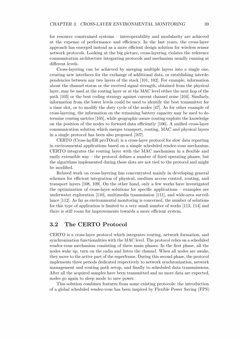
CHAPTER 3. CROSS-LAYER ENVIRONMENTAL MONITORING 39
for resource constrained systems – interoperability and modularity are achievedat the expense of performance and efficiency. In the last years, the cross-layerapproach has emerged instead as a more efficient design solution for wireless sensornetwork protocols. Looking at the big picture, cross-layering violates the referencecommunication architecture integrating protocols and mechanism usually running atdifferent levels.
Cross-layering can be achieved by merging multiple layers into a single one,creating new interfaces for the exchange of additional data, or establishing interde-pendencies between any two layers of the stack [101, 102]. For example, informationabout the channel status or the received signal strength, obtained from the physicallayer, may be used at the routing layer or at the MAC level either the next hop of thepath [103] or the best coding strategy against current channel noise [104]. Similarly,information from the lower levels could be used to identify the best transmitter fora time slot, or to modify the duty cycle of the nodes [47]. As for other example ofcross-layering, the information on the remaining battery capacity may be used to de-termine routing metrics [105], while geographic-aware routing exploits the knowledgeon the position of the nodes to forward data efficiently [106]. A unified cross-layercommunication solution which merges transport, routing, MAC and physical layersin a single protocol has been also proposed [107].
CERTO (Cross-layER proTOcol) is a cross-layer protocol for slow data reportingin environmental applications based on a simple scheduled rendez-vous mechanism.CERTO integrates the routing layer with the MAC mechanism in a flexible andeasily extensible way – the protocol defines a number of fixed operating phases, butthe algorithms implemented during these slots are not tied to the protocol and mightbe modified.
Related work on cross-layering has concentrated mainly in developing generalschemes for efficient integration of physical, medium access control, routing, andtransport layers [108, 109]. On the other hand, only a few works have investigatedthe optimization of cross-layer solutions for specific applications – examples areunderwater exploration [110], multimedia transmission [111], and wide-area surveil-lance [112]. As far as environmental monitoring is concerned, the number of solutionsfor this type of application is limited to a very small number of works [113, 114] andthere is still room for improvements towards a more efficient system.
3.2 The CERTO ProtocolCERTO is a cross-layer protocol which integrates routing, network formation, andsynchronization functionalities with the MAC level. The protocol relies on a scheduledrendez-vous mechanism consisting of three main phases. In the first phase, all thenodes wake up, turn on the radio and listen the channel. When all nodes are awake,they move to the active part of the superframe. During this second phase, the protocolimplements three periods dedicated respectively to network synchronization, networkmanagement and routing path setup, and finally to scheduled data transmissions.After all the acquired samples have been transmitted and no more data are expected,nodes go again to sleep mode to save power.
This solution combines features from some existing protocols: the introductionof a global scheduled rendez-vous has been inspired by Flexible Power Saving (FPS)
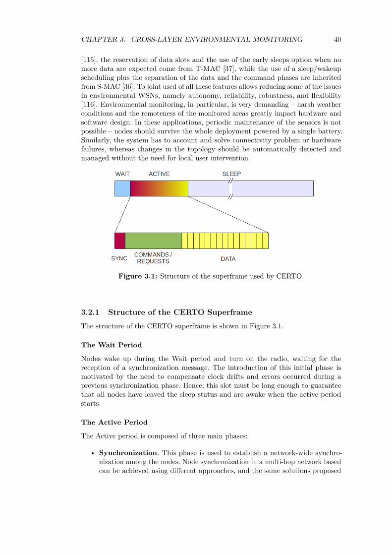
CHAPTER 3. CROSS-LAYER ENVIRONMENTAL MONITORING 40
[115], the reservation of data slots and the use of the early sleeps option when nomore data are expected come from T-MAC [37], while the use of a sleep/wakeupscheduling plus the separation of the data and the command phases are inheritedfrom S-MAC [36]. To joint used of all these features allows reducing some of the issuesin environmental WSNs, namely autonomy, reliability, robustness, and flexibility[116]. Environmental monitoring, in particular, is very demanding – harsh weatherconditions and the remoteness of the monitored areas greatly impact hardware andsoftware design. In these applications, periodic maintenance of the sensors is notpossible – nodes should survive the whole deployment powered by a single battery.Similarly, the system has to account and solve connectivity problem or hardwarefailures, whereas changes in the topology should be automatically detected andmanaged without the need for local user intervention.
Figure 3.1: Structure of the superframe used by CERTO.
3.2.1 Structure of the CERTO Superframe
The structure of the CERTO superframe is shown in Figure 3.1.
The Wait Period
Nodes wake up during the Wait period and turn on the radio, waiting for thereception of a synchronization message. The introduction of this initial phase ismotivated by the need to compensate clock drifts and errors occurred during aprevious synchronization phase. Hence, this slot must be long enough to guaranteethat all nodes have leaved the sleep status and are awake when the active periodstarts.
The Active Period
The Active period is composed of three main phases:
• Synchronization. This phase is used to establish a network-wide synchro-nization among the nodes. Node synchronization in a multi-hop network basedcan be achieved using different approaches, and the same solutions proposed
CHAPTER 3. CROSS-LAYER ENVIRONMENTAL MONITORING 41
for PRISM in Section 2.5 may be applied also to CERTO. Specifically, adistributed algorithms like the Timing-sync Protocol for Sensor Networks(TPSN) [89] might be the best choice for the hierarchical network structurebuild during the network setup phase. After having synchronized its children,each parent node broadcast a short beacon containing its identifier, the amountof connected nodes and its distance in hops from the gateway. As describedlater, the information contained in this beacon is used by new nodes whenjoining the network.
• Command. The Command phase is used to deliver messages issued by thegateway, for example to inform the nodes about a variation in the globalschedule or about a new data slot assigned to a node. Moreover, during thisphase new sensors can request to join to network, existing nodes can leave, andchanges in the routing topology can take place. The channel access is ruled byCSMA/CA, and unsent messages are postponed to the successive cycle.
• Data. The Data phase is divided into slots, and each node is assigned adedicated time slot for transmitting the acquired samples. During a certaindata slot, the source node and all the intermediate nodes of the routing pathare required to be awake, while the remaining nodes of the network can turnoff the radio and save energy.
The Sleep Period
During the Sleep period, nodes enter in power-save mode until the end of thesuperframe. This phase is crucial for saving energy: the longer it is, the lower theduty cycle will be. However, during the sleep period no commands can be issued tothe network and new nodes can not enter – a trade-off is needed between systemresponsiveness and power saving. In addition, since a longer sleep period implies lessfrequent resynchronizations, the impact of clock drifts should be taken into accountwhen configuring the network.
3.2.2 Routing in CERTO
The choice of the routing mechanism for the CERTO protocol has based on afew considerations on the functional requirements, the dynamic of the monitoredenvironment, and the economical and energetic constraints of the target application.
A classical taxonomy of routing protocols for WSNs divides them into three mainclasses: flat-based, hierarchical-based and location-based [106]. In the last case, thepositions of the nodes are exploited to design routing paths. The distance betweenneighbouring nodes and their relative location can be estimated using either a GlobalPositioning System (GPS) signal or local techniques, such as those based on thereceived signal strength, the angle of the received signal or the signal travel time.However, the use of GPS signals requires a dedicated and energy-demanding receiver,whereas the other techniques are affected by multipath noise and their accuracy isextremely variable [117].
Similarly, flat routing protocols based on gossiping or flooding schemes [118]have been discarded too – they waste energy and bandwidth sending multiple non-necessary copies of data in overlapping areas, and they can introduce significant
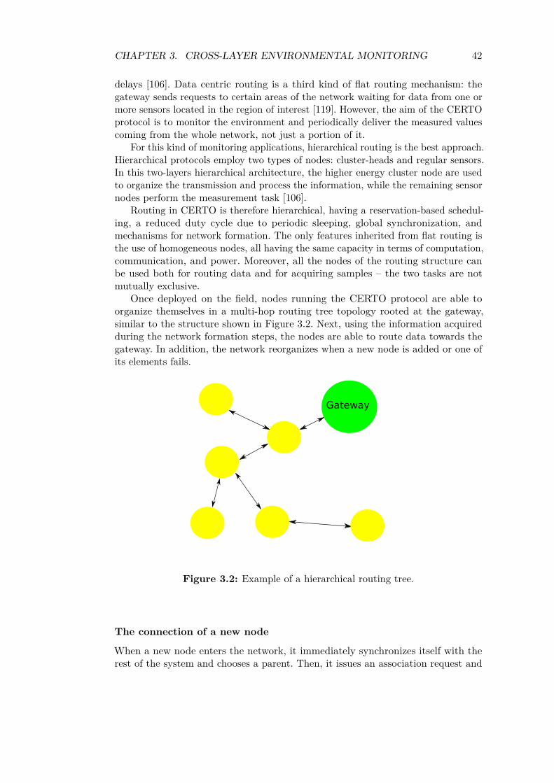
CHAPTER 3. CROSS-LAYER ENVIRONMENTAL MONITORING 42
delays [106]. Data centric routing is a third kind of flat routing mechanism: thegateway sends requests to certain areas of the network waiting for data from one ormore sensors located in the region of interest [119]. However, the aim of the CERTOprotocol is to monitor the environment and periodically deliver the measured valuescoming from the whole network, not just a portion of it.
For this kind of monitoring applications, hierarchical routing is the best approach.Hierarchical protocols employ two types of nodes: cluster-heads and regular sensors.In this two-layers hierarchical architecture, the higher energy cluster node are usedto organize the transmission and process the information, while the remaining sensornodes perform the measurement task [106].
Routing in CERTO is therefore hierarchical, having a reservation-based schedul-ing, a reduced duty cycle due to periodic sleeping, global synchronization, andmechanisms for network formation. The only features inherited from flat routing isthe use of homogeneous nodes, all having the same capacity in terms of computation,communication, and power. Moreover, all the nodes of the routing structure canbe used both for routing data and for acquiring samples – the two tasks are notmutually exclusive.
Once deployed on the field, nodes running the CERTO protocol are able toorganize themselves in a multi-hop routing tree topology rooted at the gateway,similar to the structure shown in Figure 3.2. Next, using the information acquiredduring the network formation steps, the nodes are able to route data towards thegateway. In addition, the network reorganizes when a new node is added or one ofits elements fails.
Figure 3.2: Example of a hierarchical routing tree.
The connection of a new node
When a new node enters the network, it immediately synchronizes itself with therest of the system and chooses a parent. Then, it issues an association request and

CHAPTER 3. CROSS-LAYER ENVIRONMENTAL MONITORING 43
waits for the assigned schedule from the gateway. A detailed description of the stepsperformed during this connection process follows.
1. First, a node enters the Beacon Scan phase, and listens the channel waitingfor one or more beacons issued by the parent nodes in its range.
2. Then, the node wishing to enter chooses its parent according to the informationcontained in the received beacon.
The basic rule adopted by the protocol is to choose the node with the leastnumber of associated children. However, if one the potential parents has morechildren but is also at an higher level in the routing path, it is elected as the newcandidate parent. The adoption of this simple heuristic increases fairness and aimsat building a balanced routing tree, but more complex algorithm for generating thespanning-tree could be implemented here without loss of generality.
3. Once the node has identified the potential parent, it goes back to sleep waitingfor the next wake-up cycle – the remaining time is calculated from the valuepreviously indicated in the beacon. At the end of the sleep period, the nodewakes up and waits for a random backoff delay before sending the join requestto the chosen parent node 𝑃 .
The random backoff interval has been introduced to reduce the probability ofcollisions among multiple nodes in the same range. The join request received by theparent contains the physical unique identifier of the new node, the ID of the chosenparent 𝑃 and the temporary ID of the child.
4. If the receiver node can not accept the request for some reason, it discardsthe request. Otherwise, it forwards the request to its parent node (the reasonfor ignoring the request could be that the packet has been corrupted, or theparent has already reached either the maximum number of allowed children𝑊 or the maximum hops distance 𝐻 from the gateway).
5. In its turn, this node buffers the IDs of both the candidate parent 𝑃 and theprevious hop in the routing path. Then, it forwards the request to the nexthop towards the gateway. The buffered information will be used later by theintermediate nodes to forward back the association reply. This step is repeatedby the various nodes of the path, until the message reaches the gateway.
6. Once the message is received by the gateway, the scheduling algorithm runningon it assigns a new ID to the requesting node.
7. Then, the new identifier assigned to the requesting node, together with itsphysical unique identifier and the ID of its parent 𝑃 , are sent back along thepath towards 𝑃 .
8. When 𝑃 receives the answer of the gateway, it broadcasts the message to allits listener.
CHAPTER 3. CROSS-LAYER ENVIRONMENTAL MONITORING 44
9. The actual destination receives this message, recognizes itself as the recipientfrom the unique identifier included into the message, and so acquires the newID assigned by the gateway.
10. Finally, the new node waits for the successive superframe cycle to synchronizeitself with the parent node and to begin transmitting samples.
If the request message or the answer get lost and a reply is not received withina certain timeout, the joining node issues again the request. If no reply is receivedafter 𝑛 consecutive attempts, the node moves to the next candidate in the list of thepotential father nodes. In addition, random backoffs of one or more cycles can beoptionally activated by the child to separate two retransmissions of the join request.
Delivery of Data and Commands
During the Data phase, each node acquires samples during the assigned time slotand then transmits the data packet to its parent. In turn, the parent node forwardsthe packet to its parent. The process is repeated along the path, until the messageis finally delivered to the gateway. During each time slot, the nodes involved in theforwarding path must be awake, whereas the other nodes can turn off the radio andsave energy during this interval.
Within the Command phase, the exchange of messages can be local or global,and packets can travel both to and from the gateway. The delivery of a requestfrom a node to the gateway does not differ significantly from the data transmissionprocess described above. All the nodes which hear the message discard the messageif they are not part of the path, while the next hop towards the gateway storesand forwards the packet. Similarly, a packet sent by the gateway to a specific nodeis forwarded only by the nodes along the path and discarded by the others. Theforwarding mechanism is a destination based one, with the intermediate nodes whichchoose the next hop using the information buffered during the network formationsteps. Finally, if a message is broadcast only locally, it is received and processed bythe neighbor nodes but it is not forwarded.
Node failure or exit
During normal operation, temporary failures of links may happen, for example dueto a sudden loss of connectivity produced by moving obstacle passing between twonodes, fading effects, or noise introduced by external electronic devices. Since thelink is supposed to be restored quickly, there is no reason to modify the routing path– children can ignore the problem and reschedule transmissions in the successiveperiods.
However, if the link remains down for more than 𝑛 consecutive cycles, the childrencan safely assume that the failure has become permanent, for example because theenvironment has changed or the parent node died. In this case, each child disconnectsfrom the unreachable parent and looks for a new parent, repeating the connectionprocess described in the previous section. After the node has found a new parent, theintermediate elements of the path is notified of the change in the routing structure.Moreover, they remain awake all the time during the first active phase – observingthe passing packets, they learn the IDs and the transmission slots of the new nodes.
CHAPTER 3. CROSS-LAYER ENVIRONMENTAL MONITORING 45
It is also possible that a node knows when it is going to die, namely becauseof the low battery level. If this is the case, it can inform its neighbors about itsstatus, broadcasting a specific message during the Command phase. At this point,the recipients will be able to disconnect immediately from the dying node and lookfor new fathers as soon as possible.
3.3 Configuration of CERTOThe performance of the CERTO protocol depends on the parameters set by the userwhile configuring the network, namely the three-topology thresholds, the maximumamount of reconnection attempts, or the duration of the various superframe phases.However, there are a number of aspects which need to be considered, and differentoptions may be selected depending on the number and the density of sensor nodes, thedesired network coverage, the characteristics of the environment, and the constraintson the energy budget of the nodes.
3.3.1 Tree-topology thresholds
As mentioned in the previous section, the size of the routing tree created by CERTOis bounded by two thresholds: a first value 𝐻 bounds the maximum number ofchildren per parent, while a second parameters 𝑊 limits the height of the tree.
Increasing the maximum height 𝐻 of the tree means that the information can bedelivered over more hops, allowing the system to cover longer distances. On the otherside, an increased number of hops implies larger delays in the propagation of messagesand data. On the contrary, a wider network reduces delays but requires shorterdistances among nodes or higher transmission powers. In addition, the more thechildren per node are, the higher will be the traffic load and the power consumptionof the nodes in the upper levels of the tree.
In addition, the thresholds must not be too strict – otherwise, some sensors couldnot join the network if all the neighbour nodes have already reached their childrenmaximum amount.
3.3.2 Reconnection attempts
The value 𝑛 is used by the routing functions to manage possible communicationerrors, for example when a parent can not accept requests to join from a new sensoror when it dies and is not reachable anymore. If these cases, if beacons are notreceived after 𝑛 consecutive cycles, the child chooses another parent node. A smallvalue of 𝑛 means that the network will react faster in case of a permanent nodefailure. On the other hand, this could also bring to frequent changes or instability inthe routing paths in presence of unreliable links subject to temporary failures.
3.3.3 Superframe duration
The duration of the superframe is not fixed, and depends on the length of its variousphases. Similarly, the duration of each of the phases is related to a number of factors,among which the network size, the accuracy of hardware clocks and the desiredlifetime stand out.

CHAPTER 3. CROSS-LAYER ENVIRONMENTAL MONITORING 46
Wait phase duration
The Wait phase is used to compensate clock drifts and other inaccuracies in thealignment among the clocks of the sensor nodes. Given the maximum absolute error𝜖 of the synchronization mechanism and the drift Δ of the physical clocks mountedon the sensor boards, the maximum clock error for a node is:
𝜖 + Δ · 𝑇𝑠𝑢𝑝𝑒𝑟𝑓𝑟𝑎𝑚𝑒 (3.1)
In the worst case, the discrepancy between the slowest and the fastest clocks willbe twice the absolute error defined in Equation 3.1. Hence, this means that also theminimum duration of the Wait phase should be:
𝑇𝑤𝑎𝑖𝑡 = 2(𝜖 + Δ · 𝑇𝑠𝑢𝑝𝑒𝑟𝑓𝑟𝑎𝑚𝑒) (3.2)
This minimum value can guarantee that all nodes will be awake when theactive period starts. Longer slots might be used for increasing the reliability ofthe mechanism, but at the cost of an increased energy consumption – once awake,the nodes turn on the radio and overhear the channel all the time, waiting for thesynchronization signal.
Synchronization phase duration
The length of the synchronization phase is strictly related to the network size andthe implemented synchronization mechanism. If a single reference signal is broadcastfrom the root node, its duration plus the processing time is the minimum length ofthe phase. If a different protocol is used instead, this value changes as well.
For example, the TPSN protocol performs synchronization in rounds along thetree – each round is initiated by the parent node, which aligns each of its childrenthrough round-trip measurements. In this case, given the duration 𝑇𝑆 of a singlechild-parent measurement, the worst-case duration 𝑇𝑠𝑦𝑛𝑐ℎ of the synchronizationprocess for the whole network depends on the height 𝐻 and width 𝑊 of the routingtree:
𝑇𝑠𝑦𝑛𝑐ℎ = 𝑇𝑆 ·𝐻𝑚𝑎𝑥 ·𝑊𝑚𝑎𝑥 (3.3)
Command phase length
The duration of this phase is related the network management activities. Ideally, itshould last enough to guarantee that all configurations and routing commands areexchanged successfully – if the interval is too short, an important message may bedelayed or could even starve in the output queue. However, since all the nodes mustlisten the channel during this phase, longer periods increase energy consumption aswell.
Data phase size
The part of the superframe devoted to the transmissions of samples consists of atleast 𝑋 equally sized time slots, where 𝑋 is the number of active sensor nodes inthe network:
𝑇𝑑𝑎𝑡𝑎 = 𝑋 · 𝑇𝑠𝑙𝑜𝑡 (3.4)

CHAPTER 3. CROSS-LAYER ENVIRONMENTAL MONITORING 47
Moreover, each slot must be large enough to guarantee that even the farthest nodeof the network can deliver samples in time. Hence, given the time 𝑇𝑎𝑐𝑞 taken by anode to acquire sample and the one hop propagation time 𝑇𝑝𝑟𝑜𝑝, the total durationof the Data phase can be calculated as:
𝑇𝑑𝑎𝑡𝑎 = 𝑋 · 𝑇𝑠𝑙𝑜𝑡 = 𝑋 · (𝑇𝑎𝑐𝑞 + 𝐻𝑚𝑎𝑥 · 𝑇𝑝𝑟𝑜𝑝) (3.5)
Sleep and duty cycle
Energy saving in this network is achieved by putting the sensor nodes in sleep modeas much as possible. While the length of the active part of the frame is more or lessfixed, the duration 𝑇𝑠𝑙𝑒𝑒𝑝 of the sleep phase can be adjusted to match the desiredefficiency. As shown in Equation 3.6, the duty cycle 𝛿 will decrease with a longersleep phase:
𝛿 = 𝑇𝑠𝑙𝑒𝑒𝑝
𝑇𝑠𝑢𝑝𝑒𝑟𝑓𝑟𝑎𝑚𝑒= 𝑇𝑠𝑙𝑒𝑒𝑝
𝑇𝑎𝑐𝑡𝑖𝑣𝑒 + 𝑇𝑠𝑙𝑒𝑒𝑝(3.6)
However, each node transmits data once in every cycle – the delay between twoconsecutive packets from the same sensor is therefore 𝑇𝑠𝑢𝑝𝑒𝑟𝑓𝑟𝑎𝑚𝑒.
This means that an increased duration of sleep phase can improve the energyefficiency and the lifetime of the sensor network but, at the same time, can limit thetimeliness and responsiveness of the system.
3.4 Experimental evaluationThe CERTO protocol has been implemented with the purpose of evaluating itssuitability for low-power and memory constrained sensor node. Then, this prototypeimplementation of the CERTO stack has been compiled and run in a simple networkof Libelium’s SquidBee devices [98]. Squibee is a wireless sensing platform based onthe Atmel ATMega168 microcontroller, an 8-bit processor running at 16 MHz andfeaturing 1024 bytes of SRAM, an EEPROM memory of 512 bytes, and 15 KBytesof programmable flash plus 1 KB used to store the bootloader. The wireless part ofthis development platform is powered by an IEEE 802.15.4-compliant MaxStreamXBee radio module [120].
A working implementation of CERTO written in C language fits in 325 lines ofsource code, coupled with a library of about 1200 lines containing basic input/outputand wireless communication functions. This resulted also in an executable with alimited footprint: the binary version of stack produced by the gcc-avr cross-compilerfor the ATMega168 processor requires just 8 Kbytes of ROM.
A number of experiments have been carried out both in indoor and outdoor sce-narios in order to find an adequate configuration for the various network parameters.Similarly, an investigation of the main challenges related to radio signal propagationhas suggested some node placement strategies for increasing the reliability of thewireless links. Using the results obtained from these tests, a small network was finallyconfigured, deployed, and used to collected environmental parameters for hours.

CHAPTER 3. CROSS-LAYER ENVIRONMENTAL MONITORING 48
Table 3.1: Forwarding time with different hop distances.
Distance Time (𝑠)1 hop 49.8± 9.32 hops 153.3± 16.03 hops 257.0± 17.74 hops 360.0± 19.2
3.4.1 Network configuration parameters
A preliminary evaluation of the working protocol was made in a controlled laboratoryenvironment, using four Squidbee devices. The network was a static one, and thenodes were forced to self-organize in a star topology. The system ran successfully forthree hours, delivering samples periodically without losing any packets.
The test was repeated configuring the network in a line topology with the gatewayas the first node, as shown in Figure 3.3. The protocol proved to be reliable, deliveringall the packets in this multi-hop configuration. Moreover, this experiment provideduseful information for determining the correct configuration values of the CERTOparameters described in the previous section
Figure 3.3: Example of line topology.
During this last test, the gateway collected also the time taken by each nodeto deliver the packets during the assigned slot. The average values obtained fromthe testbed are shown in Table 3.1. The generation of a packet and its transmissiontook about 50 𝑚𝑠 on the source node, whereas each intermediate node introducedan additional delay of about 100 𝑚𝑠 for processing the packet and forwarding it tothe next hop of the path towards the gateway. These values are useful to determinethe minimum duration of the data slots, given the maximum depth in hops of therouting tree.
According to the experimental values obtained from the controlled testbed, this
CHAPTER 3. CROSS-LAYER ENVIRONMENTAL MONITORING 49
would allow to assign time slots of 0.5 𝑠 to each node. Similarly, the synchronizationprotocol implemented on the nodes requires about 500 ms per hop, and the processprovides a clock alignment with a maximum error of 2 𝑚𝑠. However, the testsrevealed that the radio module can take up to 300-400 𝑚𝑠 to completely wake upand get ready to receive or transmit packets. For this reason, the minimum durationof the Wait phase must be at least 500 𝑚𝑠. Finally, the duration of the Commandphase depends on the estimated average amount of topology changes, requests tojoin by new nodes or configuration command issued by users: a slot length of about4 𝑠 can guarantee the correct delivery of 4-5 messages. This value might be sufficientfor static networks of tens of nodes, while a wider network would require a longerCommand phase.
These values, together with the network size, can be used to estimate the lifespanof the whole network. For example, let’s consider 20 nodes deployed on the field andorganized on a routing tree of 4 hops. According to the experimental values obtainedfrom the controlled testbed, this would allow to assign time slots of 0.5 𝑠 to eachnode, for a total of a 10 𝑠 superframe data transmission slot. Adding other 0.5 𝑠 forthe wait phase, 2 𝑠 for the synchronization mechanism and a command period of 4 𝑠,we get an active part of the superframe lasting for 16.5 𝑠. If the network is supposedto acquire and send data every 5 minutes, the resulting duty cycle is 0.055%. Asnoted in Section 2.7, the maximum lifetime of an optimized Squidbee node in activestate is about 10 days - therefore, the achievable lifespan of this network can beestimated in 180 days, that is 6 months of operation.
3.4.2 Nodes placement strategies
Radio propagation is a key element for the success of an environmental wirelesssensor network, and node placement is a crucial task for achieving an adequatecoverage and quality of links. In this context, the height of a node over the terrain, aswell as environmental factors may influence the reliability of the wireless connectionsand the maximum allowable distance.
In order to identify sensor placement strategies to increase the reliability ofwireless links, a number of experiments have been carried out in four differentenvironments. The first considered scenario is an indoor one, that is the Departmentof Electronics of the University of Pavia. It can be considered as an harsh environmentdue to the presence of walls, long passageways, a 4 𝑚 ceiling, active WiFi accesspoints, and a lot of moving obstacles (people). Other tests have been carried outoutdoor in the University campus, characterized by grass fields, concrete pavements,sparse trees, and again walking people crossing the scene. The same experiments havebeen then repeated in a crop field, with two nodes in line of sight and without notableobstacles in the surrounding environment. Finally, the last considered scenario is asmall woodland in the Vernavola city park, just outside the town of Pavia.
In all the scenarios described above, the sender and the receiver nodes were put inline of sight 25 meters far from each other – this can be considered a realistic distancefor wide-scale environmental application. The nodes were deployed randomly in fourdifferent positions in each scenario, and for each configuration 100 packets weretransmitted from the source device to the recipient sensor node. A first batch oftests was performed putting the two nodes at ground level, but all the experiments
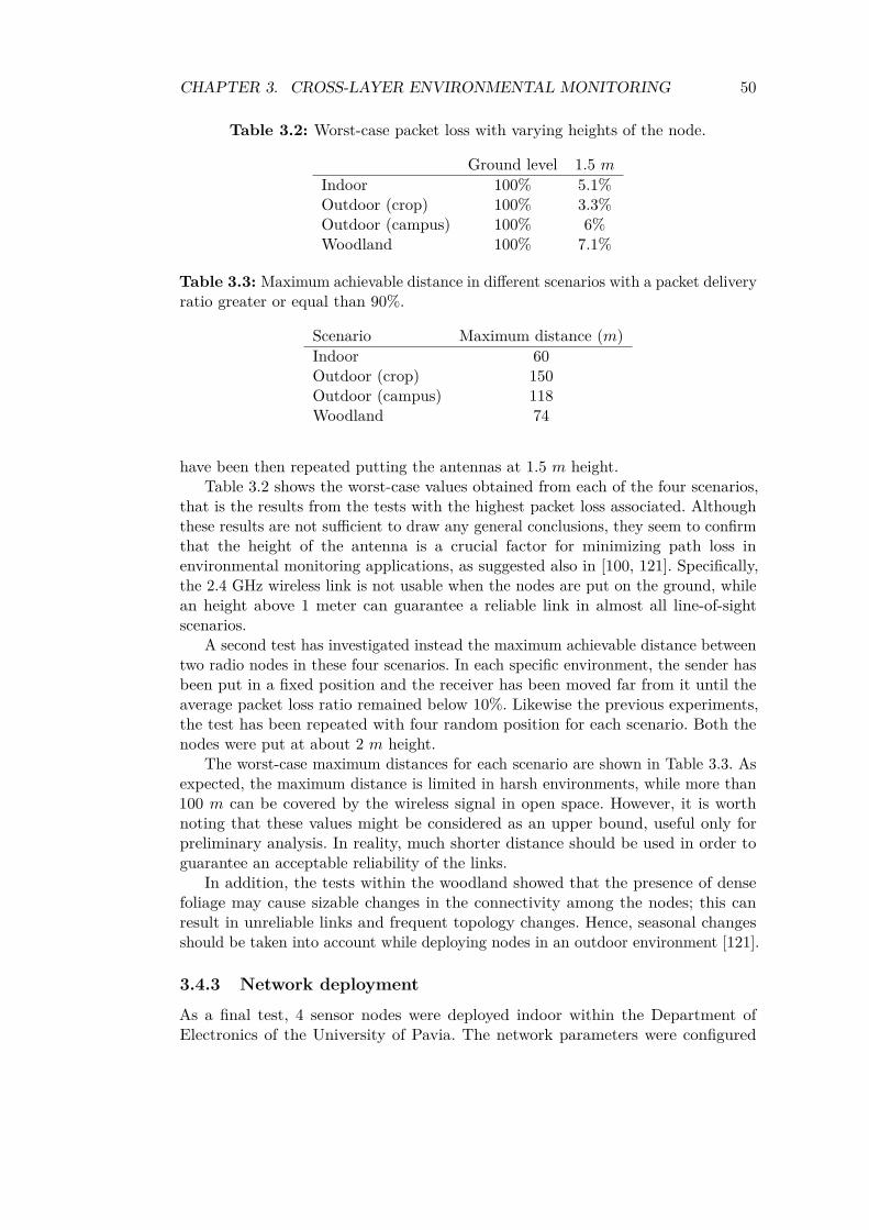
CHAPTER 3. CROSS-LAYER ENVIRONMENTAL MONITORING 50
Table 3.2: Worst-case packet loss with varying heights of the node.
Ground level 1.5 𝑚
Indoor 100% 5.1%Outdoor (crop) 100% 3.3%Outdoor (campus) 100% 6%Woodland 100% 7.1%
Table 3.3: Maximum achievable distance in different scenarios with a packet deliveryratio greater or equal than 90%.
Scenario Maximum distance (𝑚)Indoor 60Outdoor (crop) 150Outdoor (campus) 118Woodland 74
have been then repeated putting the antennas at 1.5 𝑚 height.Table 3.2 shows the worst-case values obtained from each of the four scenarios,
that is the results from the tests with the highest packet loss associated. Althoughthese results are not sufficient to draw any general conclusions, they seem to confirmthat the height of the antenna is a crucial factor for minimizing path loss inenvironmental monitoring applications, as suggested also in [100, 121]. Specifically,the 2.4 GHz wireless link is not usable when the nodes are put on the ground, whilean height above 1 meter can guarantee a reliable link in almost all line-of-sightscenarios.
A second test has investigated instead the maximum achievable distance betweentwo radio nodes in these four scenarios. In each specific environment, the sender hasbeen put in a fixed position and the receiver has been moved far from it until theaverage packet loss ratio remained below 10%. Likewise the previous experiments,the test has been repeated with four random position for each scenario. Both thenodes were put at about 2 𝑚 height.
The worst-case maximum distances for each scenario are shown in Table 3.3. Asexpected, the maximum distance is limited in harsh environments, while more than100 𝑚 can be covered by the wireless signal in open space. However, it is worthnoting that these values might be considered as an upper bound, useful only forpreliminary analysis. In reality, much shorter distance should be used in order toguarantee an acceptable reliability of the links.
In addition, the tests within the woodland showed that the presence of densefoliage may cause sizable changes in the connectivity among the nodes; this canresult in unreliable links and frequent topology changes. Hence, seasonal changesshould be taken into account while deploying nodes in an outdoor environment [121].
3.4.3 Network deployment
As a final test, 4 sensor nodes were deployed indoor within the Department ofElectronics of the University of Pavia. The network parameters were configured
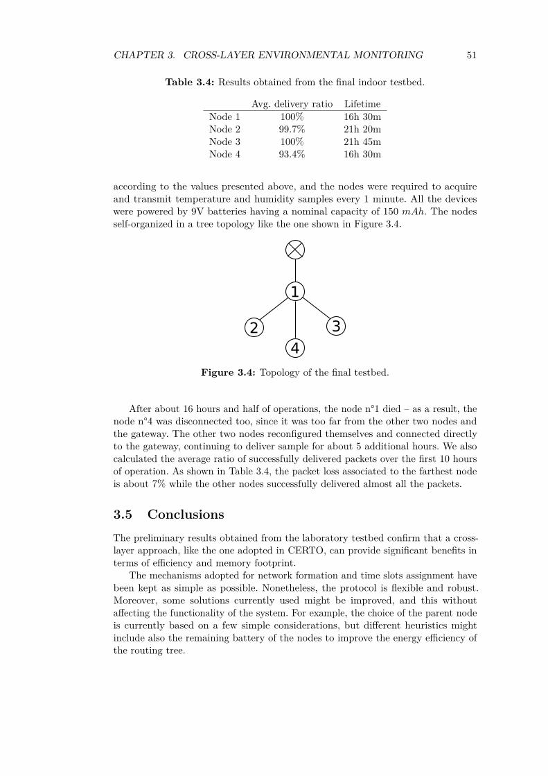
CHAPTER 3. CROSS-LAYER ENVIRONMENTAL MONITORING 51
Table 3.4: Results obtained from the final indoor testbed.
Avg. delivery ratio LifetimeNode 1 100% 16h 30mNode 2 99.7% 21h 20mNode 3 100% 21h 45mNode 4 93.4% 16h 30m
according to the values presented above, and the nodes were required to acquireand transmit temperature and humidity samples every 1 minute. All the deviceswere powered by 9V batteries having a nominal capacity of 150 𝑚𝐴ℎ. The nodesself-organized in a tree topology like the one shown in Figure 3.4.
1
2 3
4
Figure 3.4: Topology of the final testbed.
After about 16 hours and half of operations, the node n°1 died – as a result, thenode n°4 was disconnected too, since it was too far from the other two nodes andthe gateway. The other two nodes reconfigured themselves and connected directlyto the gateway, continuing to deliver sample for about 5 additional hours. We alsocalculated the average ratio of successfully delivered packets over the first 10 hoursof operation. As shown in Table 3.4, the packet loss associated to the farthest nodeis about 7% while the other nodes successfully delivered almost all the packets.
3.5 ConclusionsThe preliminary results obtained from the laboratory testbed confirm that a cross-layer approach, like the one adopted in CERTO, can provide significant benefits interms of efficiency and memory footprint.
The mechanisms adopted for network formation and time slots assignment havebeen kept as simple as possible. Nonetheless, the protocol is flexible and robust.Moreover, some solutions currently used might be improved, and this withoutaffecting the functionality of the system. For example, the choice of the parent nodeis currently based on a few simple considerations, but different heuristics mightinclude also the remaining battery of the nodes to improve the energy efficiency ofthe routing tree.
CHAPTER 3. CROSS-LAYER ENVIRONMENTAL MONITORING 52
A second test outdoor in an open field, showed that burst of packets are lost ifthe distance among two connected nodes is higher than 50-60 meters. The reasonsfor this unwanted behaviour are the changes in the network topology caused bythe instability of low-power wireless links over long distances. This advocates forthe implementation of a more complex heuristic for the organization of the routingpaths, including for example information coming from the physical layer. The useof the Received Signal Strength Index or the Link Quality Indicator obtained fromradio module could provide additional criteria for the choice of the best parent node.
Further investigations might concentrate also on the duration of the variousphases of the CERTO superframe, which currently need to be set empirically by theuser. A theoretical analysis of the clock drifts, the synchronization errors and theprocessing times could provide optimal values for these intervals.
Finally, the responsiveness of the system is related to the sampling frequencyused to monitor the process – messages can not be delivered to the network duringthe sleep phase. A possible improvement would be the introduction of one or moreshort wake-ups during the inactive phase, useful for re-synchronizing nodes andissuing commands with reduced delays.
Chapter 4
A RESTful Interface for WSNs
4.1 IntroductionAny sensor networks implementing the MAC protocols described in the previouschapters, as well as most of wireless monitoring systems proposed in literature, includeone or more gateway nodes. Data acquired by the various sensors are transmitted tothis central node, and are used to acquire information about the network from theoutside.
As described in Section 1.3, the REST approach has recently emerged as a viableand efficient solution for interfacing a sensor network to the external world. The mainstrength of a RESTful approach is the usage of standard technologies and protocols,which simplify the interconnection to the Internet. For example, the network can beeasily queried with standard HTTP requests. This approach considerably reducesthe complexity of the communication protocols involved, increasing at the same timethe responsiveness of the system and reducing the channel demand [77, 78].
This chapter tries to take a step further compared to past works by proposing amodular RESTful architecture that can be easily adapted for different applicationswith only small changes. Access to each and every data source — which maps to asingle sensor node — is enabled by a RESTful interface over the HTTP protocol.The communication exploits the standard HTTP methods GET, POST, PUT andDELETE, and the access to specific resources is mapped over a URL. As thisRESTful interface has not been standardized, this work tries to put down a set ofgeneral purpose rules which could help in defining it in a general and rigorous way.
There is a need for an open collection infrastructure for WSNs to ease data col-lection and analysis of measures gathered from real-world deployments of monitoringapplications. The openness should be both structural and material: on one side, anopen database schemas simplify the efforts needed to share information. On theother side, the adoption of an infrastructure based on open-source software makeseasier for everyone to study, use and improve it.
With the aim of providing a reference implementation for further development,also a fully open RESTful Environmental DataBase (REnvDB) was implemented,able to mashup the information coming from the sensors. The result is a flexible and
Published as: E. Goldoni, A. Savioli, F. De Stefani, D. Silvestri, F. Toffalini, and P. Gamba,“REnvDB, A RESTful Database for Pervasive Environmental Wireless Sensor Networks,” In Proc.of IEEE ICDCS Workshops, pp. 206–212, 21–25 June 2010, Genova, Italy.
53
CHAPTER 4. A RESTFUL INTERFACE FOR WSNS 54
extensible system which can be implemented in many monitoring applications. Infact, the behaviour and the content of the replies are not fixed, and can be definedin order to meet the requirements of a specific context. In the following section, amethodology to couple this RESTful architecture with the PRISM protocol (seeChapter 2), to assist in real-time monitoring of structures and buildings, is shown.
4.2 REST for Environmental MonitoringAs noted in Chapter 1, environmental WSNs usually consist of tens or hundredsof nodes distributed in crops, fields, or forests. This system may be used eitherfor monitoring the long-term evolution of slowly varying parameters, such as light,temperature, and humidity, or for raising alarms in case of critical events, likefire, landlides or floods. The collected data need to be stored and made availableto external experts (which could be humans or automatic systems), potentiallygeographically far from the WSN. The main obstacle to this goal is therefore thedesign of an efficient, flexible, and standard infrastructure able to interconnect allthe components of the system.
Once the gateway has received the environmental values from the various sensors,it needs to save them somewhere. A widely accepted solution is the storage of theacquired data in a database management system. However, past works on this topiclack a systematical organization of the collected data in a well-documented databaseschema. This impairs advanced data handling and the re-usability of the system forsimilar application.
To overcome these limitations, in the following section the constraints andrequirements of typical environmental applications are identified and analyzed.These requirements are then used as the ground work for the design of a commondatabase schema for data collection in environmental WSNs. This database is flexibleenough so that it can be implemented in most of pervasive WSN for environmentalmonitoring. Finally, a RESTful interface [122] is adapted to the database, so thatthe status and the values of parameters of the network can be easily retrieved withstandard HTTP queries.
The outcome of this design work is a RESTful interface which is able to exposedifferent types of WSNs to an external TCP/IP network, such as the Internet.Specifically, the sensor nodes transmit the acquired data to the gateway, whichstores them into the database. Using REST instructions, the users can then submitarbitrary requests to the web server — and in turn to the database — to obtainthe desired information about the monitored area. The returned values are finallycombined with mapping information and the resulting mashup is displayed througha simple web application.
Although this architecture is fully hardware and software agnostic, in Section 4.2.3a sample implementation based on open source software and low-cost hardware isdescribed – a working implementation of the REST-enabled monitoring system thathas been deployed in a real world agricultural scenario.
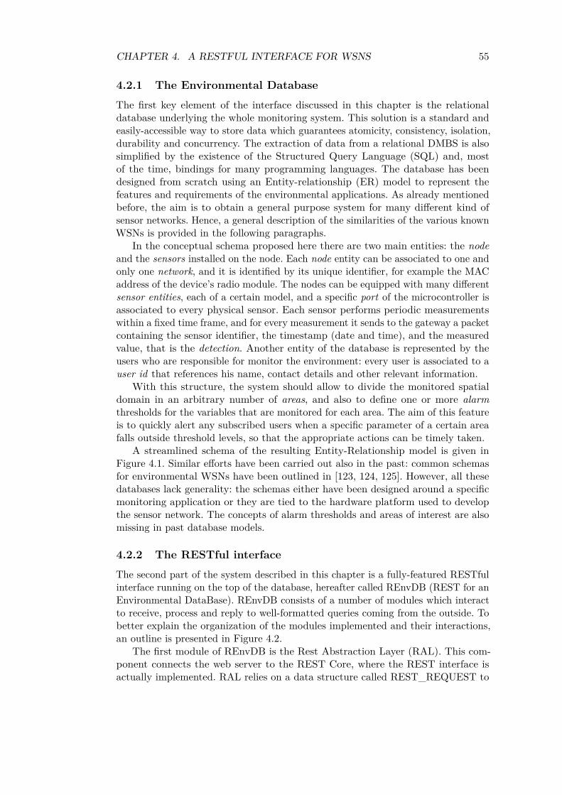
CHAPTER 4. A RESTFUL INTERFACE FOR WSNS 55
4.2.1 The Environmental Database
The first key element of the interface discussed in this chapter is the relationaldatabase underlying the whole monitoring system. This solution is a standard andeasily-accessible way to store data which guarantees atomicity, consistency, isolation,durability and concurrency. The extraction of data from a relational DMBS is alsosimplified by the existence of the Structured Query Language (SQL) and, mostof the time, bindings for many programming languages. The database has beendesigned from scratch using an Entity-relationship (ER) model to represent thefeatures and requirements of the environmental applications. As already mentionedbefore, the aim is to obtain a general purpose system for many different kind ofsensor networks. Hence, a general description of the similarities of the various knownWSNs is provided in the following paragraphs.
In the conceptual schema proposed here there are two main entities: the nodeand the sensors installed on the node. Each node entity can be associated to one andonly one network, and it is identified by its unique identifier, for example the MACaddress of the device’s radio module. The nodes can be equipped with many differentsensor entities, each of a certain model, and a specific port of the microcontroller isassociated to every physical sensor. Each sensor performs periodic measurementswithin a fixed time frame, and for every measurement it sends to the gateway a packetcontaining the sensor identifier, the timestamp (date and time), and the measuredvalue, that is the detection. Another entity of the database is represented by theusers who are responsible for monitor the environment: every user is associated to auser id that references his name, contact details and other relevant information.
With this structure, the system should allow to divide the monitored spatialdomain in an arbitrary number of areas, and also to define one or more alarmthresholds for the variables that are monitored for each area. The aim of this featureis to quickly alert any subscribed users when a specific parameter of a certain areafalls outside threshold levels, so that the appropriate actions can be timely taken.
A streamlined schema of the resulting Entity-Relationship model is given inFigure 4.1. Similar efforts have been carried out also in the past: common schemasfor environmental WSNs have been outlined in [123, 124, 125]. However, all thesedatabases lack generality: the schemas either have been designed around a specificmonitoring application or they are tied to the hardware platform used to developthe sensor network. The concepts of alarm thresholds and areas of interest are alsomissing in past database models.
4.2.2 The RESTful interface
The second part of the system described in this chapter is a fully-featured RESTfulinterface running on the top of the database, hereafter called REnvDB (REST for anEnvironmental DataBase). REnvDB consists of a number of modules which interactto receive, process and reply to well-formatted queries coming from the outside. Tobetter explain the organization of the modules implemented and their interactions,an outline is presented in Figure 4.2.
The first module of REnvDB is the Rest Abstraction Layer (RAL). This com-ponent connects the web server to the REST Core, where the REST interface isactually implemented. RAL relies on a data structure called REST_REQUEST to
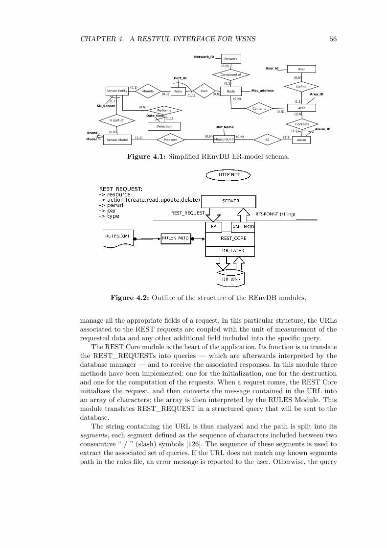
CHAPTER 4. A RESTFUL INTERFACE FOR WSNS 56
Composed of
Network
Node
(0,N)
(0,1)
Mac_address
Sensor Model
Brand
Model
Performs
Detection
(0,N)
(1,1)Date_time
MeasureUnitMeasure(1,1)
Contains
Unit Name
(0,N)
UserUser_id
Alarm
Alarm_ID
Mounts(0,1)
(0,N)
Network_ID
Area
Area_ID
(0,N)
Define
(1,1)
Contains
(1,1)
(0,N)
Sensor Entity
Is part of
(0,N)
(1,1)
SN_Sensor
(0,N)
A1(0,N) (0,N) (1,1)
OwnPorts
Port_ID
(1,1)(0,1)
Figure 4.1: Simplified REnvDB ER-model schema.
Figure 4.2: Outline of the structure of the REnvDB modules.
manage all the appropriate fields of a request. In this particular structure, the URLsassociated to the REST requests are coupled with the unit of measurement of therequested data and any other additional field included into the specific query.
The REST Core module is the heart of the application. Its function is to translatethe REST_REQUESTs into queries — which are afterwards interpreted by thedatabase manager — and to receive the associated responses. In this module threemethods have been implemented: one for the initialization, one for the destructionand one for the computation of the requests. When a request comes, the REST Coreinitializes the request, and then converts the message contained in the URL intoan array of characters; the array is then interpreted by the RULES Module. Thismodule translates REST_REQUEST in a structured query that will be sent to thedatabase.
The string containing the URL is thus analyzed and the path is split into itssegments, each segment defined as the sequence of characters included between twoconsecutive “ / ” (slash) symbols [126]. The sequence of these segments is used toextract the associated set of queries. If the URL does not match any known segmentspath in the rules file, an error message is reported to the user. Otherwise, the query
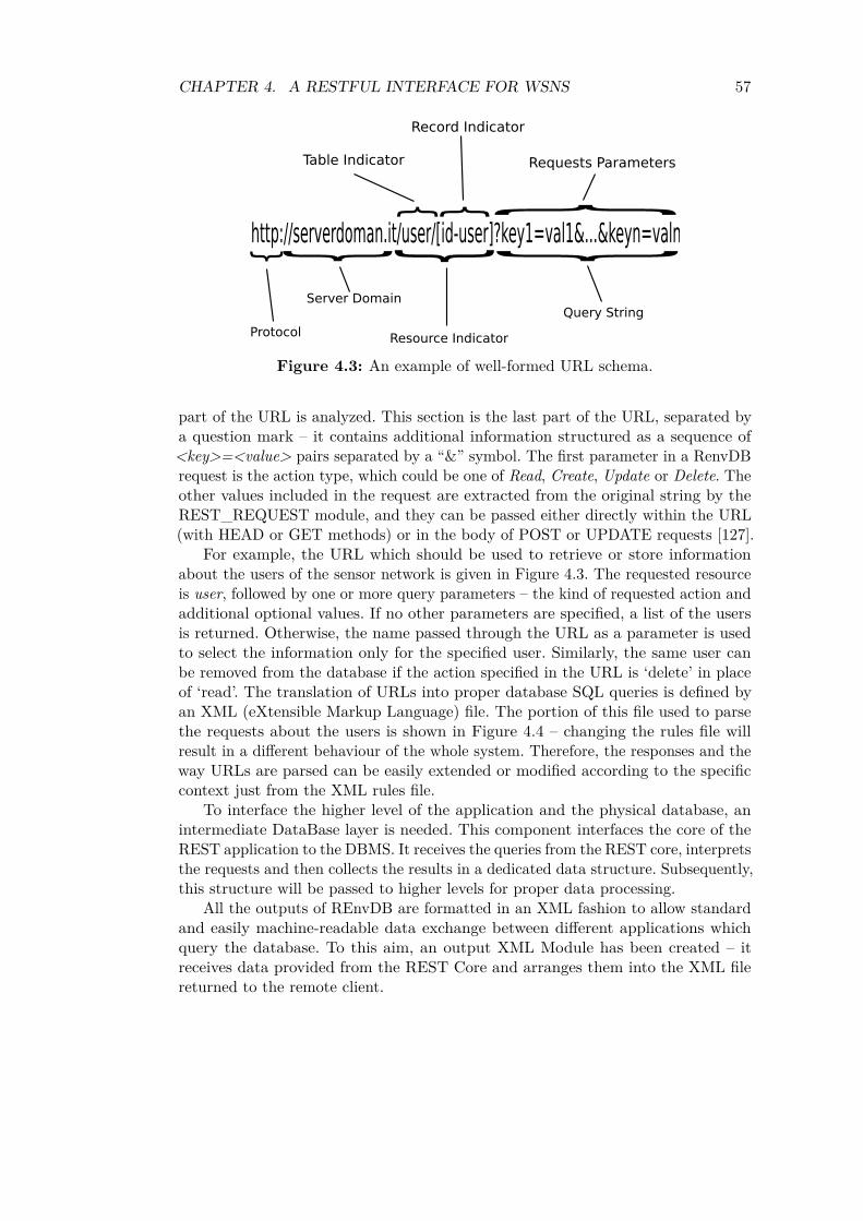
CHAPTER 4. A RESTFUL INTERFACE FOR WSNS 57
Server Domain
http://serverdoman.it/user/[id-user]?key1=val1&...&keyn=valn} } } }Protocol
Resource Indicator
Query String
Table Indicator
Record Indicator
Requests Parameters}}}
Figure 4.3: An example of well-formed URL schema.
part of the URL is analyzed. This section is the last part of the URL, separated bya question mark – it contains additional information structured as a sequence of<key>=<value> pairs separated by a “&” symbol. The first parameter in a RenvDBrequest is the action type, which could be one of Read, Create, Update or Delete. Theother values included in the request are extracted from the original string by theREST_REQUEST module, and they can be passed either directly within the URL(with HEAD or GET methods) or in the body of POST or UPDATE requests [127].
For example, the URL which should be used to retrieve or store informationabout the users of the sensor network is given in Figure 4.3. The requested resourceis user, followed by one or more query parameters – the kind of requested action andadditional optional values. If no other parameters are specified, a list of the usersis returned. Otherwise, the name passed through the URL as a parameter is usedto select the information only for the specified user. Similarly, the same user canbe removed from the database if the action specified in the URL is ‘delete’ in placeof ‘read’. The translation of URLs into proper database SQL queries is defined byan XML (eXtensible Markup Language) file. The portion of this file used to parsethe requests about the users is shown in Figure 4.4 – changing the rules file willresult in a different behaviour of the whole system. Therefore, the responses and theway URLs are parsed can be easily extended or modified according to the specificcontext just from the XML rules file.
To interface the higher level of the application and the physical database, anintermediate DataBase layer is needed. This component interfaces the core of theREST application to the DBMS. It receives the queries from the REST core, interpretsthe requests and then collects the results in a dedicated data structure. Subsequently,this structure will be passed to higher levels for proper data processing.
All the outputs of REnvDB are formatted in an XML fashion to allow standardand easily machine-readable data exchange between different applications whichquery the database. To this aim, an output XML Module has been created – itreceives data provided from the REST Core and arranges them into the XML filereturned to the remote client.

CHAPTER 4. A RESTFUL INTERFACE FOR WSNS 58
<? xml v e r s i o n e=" 1 .0 " encoding="UTF−8" ?><r u l e s>
<!−− h t t p : // example . com/ user /? ac t ion = . . . −−><element>
<user><a c t i o n>
<read>SELECT ∗ FROM user ;
</ read><c r e a t e>
INSERT INTO user ( id_user , name , surname , email , password , user_type )VALUES ( " [ id_user ] " , " [ name ] " , " [ surname ] " , " [ emai l ] " ," [ password ] " , " [ user_type ] " ) ;
</ c r e a t e></ a c t i o n><!−− h t t p : // example . com/ user /UserName/? ac t ion = . . . −−><element>
<val> <!−− UserName i s s t o r ed in ’ [ 0 ] ’ −−><a c t i o n>
<read>SELECT ∗ FROM user WHERE id_user=" [ 0 ] "
</ read><update>
UPDATE user SET name=" [ name ] " , surname=" [ surname ] " , emai l=" [ emai l ] " ,password=" [ password ] " , user_type=" [ user_type ] " WHEREid_user=" [ 0 ] " ;
</ update><d e l e t e>
DELETE FROM user WHERE id_user=" [ 0 ] " ;</ d e l e t e>
</ query></ va l>
</ element></ element>
<node>. . .
Figure 4.4: Examples of rules for parsing the REST requests.
4.2.3 The integration with CERTO protocol
The prototype system previously described in Chapter 3 has been extended in orderto integrate the REnvDB architecture with the CERTO protocol.
The main task running on the gateway has been modified, so that the acquiredvalues are stored in a local database. The DataBase Management System (DBMS)used in this project is SQLite [128], a public domain lightweight database managerthat can be easily interfaced to C language. Due to the small memory requirementsof this DBMS, it is possible to use as gateway a computer with small computationalpower and low power consumption. This is a serious advantage, since the gateway isusually placed near the WSN, often off-grid and powered by battery or solar cells.
The storage memory of the gateway, which is actually a Koala Nano PC, can beexpanded with a Compact Flash card. Moreover, the computational power of thisdevice is adequately sized to run both the Web server and an instance of the database.Hence, both the REST database and the web server have been implemented on it.In this way, less hardware devices are used, resulting also in a more compact andcheaper system.
After the design and development phases, seven sensor nodes have been deployed
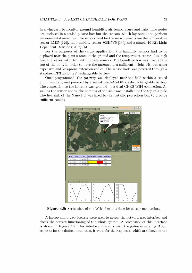
CHAPTER 4. A RESTFUL INTERFACE FOR WSNS 59
in a vineyard to monitor ground humidity, air temperature and light. The nodesare enclosed in a sealed plastic box but the sensors, which lay outside to performenvironmental measures. The sensors used for the measurements are the temperaturesensor LM35 [129], the humidity sensor 808H5V5 [130] and a simple 10 KΩ LightDependent Resistor (LDR) [131].
For the purposes of the target application, the humidity sensors had to bedeployed near the plant’s roots in the ground and the temperature sensors 2 𝑚 highover the leaves with the light intensity sensors. The SquidBee box was fixed at thetop of the pole, in order to have the antenna at a sufficient height without usingexpensive and loss-prone extension cables. The sensor node was powered through astandard PP3 Li-Ion 9𝑉 rechargeable battery.
Once programmed, the gateway was deployed near the field within a sealedaluminum box, and powered by a sealed Lead-Acid 6𝑉 -12𝐴ℎ rechargeable battery.The connection to the Internet was granted by a dual GPRS-WiFi connection. Aswell as the sensor nodes, the antenna of the sink was installed at the top of a pole.The heatsink of the Nano PC was fixed to the metallic protection box to providesufficient cooling.
Figure 4.5: Screenshot of the Web User Interface for sensor monitoring.
A laptop and a web browser were used to access the network user interface andcheck the correct functioning of the whole system. A screenshot of this interfaceis shown in Figure 4.5. This interface interacts with the gateway sending RESTrequests for the desired data; then, it waits for the responses, which are shown in the
CHAPTER 4. A RESTFUL INTERFACE FOR WSNS 60
interface as soon as they are available. The web interface has been written in PHPlanguage and relies on the Dojo Javascript toolkit [132] for the dynamic generationand update of maps, graphs, and table elements. The web application runs on alighttpd web server [133] installation accessible from the local network.
Through the main tab of the user interface it is possible to have a visualrepresentation of the status of every node on a satellite view of the area. It is alsopossible to read temperature, humidity and light intensity values in a table, and viewthe trend of these parameters on the past 24 hours, their maximum and minimumvalues. In the other tabs, it is possible to manage the alarms of every area, performhistorical data analysis and view the health state of every node of the sensor network.The user can set the maximum and minimum threshold for each of the monitoredparameters, and an alarm is triggered when they go out-of-range.
Finally, the system is able to get data from the database with a variable timeinterval, and the extracted information can be displayed directly in the browserwindows or downloaded for further processing as a CSV or EEML-formatted [134]file.
4.2.4 Preliminary Results and Lessons Learned
The first performed test had the goal of finding the maximum distance that the radioscould cover. The aim was to monitor the widest possible area with the minimumnumber of nodes. To maximize the radio performances, the XBee transceivers wereequipped with omni-directional antennas, replacing the on-chip ones. For the firstattempt, the sensor node antennas were deployed at the ground level, but themaximum distance covered was less then 10 𝑚. The antennas were then placed on apole, so that the radio link could cover up to 150 𝑚 with a packet loss of less than5%.
Once deployed on the field, the system ran for one day, acquiring data from theseven sensor nodes every 5 minutes. The final size of the database dump was about500 KByte, which means about 200 Byte per stored measurement. The responsivenessof the web interface did not exhibit any notable delay or slow down during the wholetest, and it was also possible to see updated sensed values in real-time on the map.However, it is worth noticing that most of database queries were read-only SELECT– increasing the number of nodes, the sampling frequency and even the amount ofconcurrent users could significantly impact the performance of the whole system.This issue can be easily avoided using a more powerful computer as gateway, or amore efficient database management system. Such a change would probably imply anincreased power consumption, but it would not require any change on the remainingcomponents of the sensor network.
A possible obstacle to the adoption of the proposed infrastructure is the lack ofinteroperability between different WSNs – each network tends to use a different andincompatible protocol from the others, impeding communication and data sharing.To overcome this problem, the central gateway must be able to interact with everyWSN, acting as a translation layer by relaying data and commands between theWSN and the higher layers. This is done by equipping the gateway with one sink forevery different type of WSN, thus allowing to link the sensor network to the database.For example, the gateway could be equipped with an IP router, to interface with an
CHAPTER 4. A RESTFUL INTERFACE FOR WSNS 61
IP based sensor network, or with a network-specific data proxy, to interface withproprietary WSNs.
4.3 REST for Structural MonitoringThanks to its modular design, the same RESTful architecture can be reused indifferent contexts, from home automation to structural monitoring, with minimumvariations. Different applications monitor different parameters and have differentrequirements, so the schema of the database will have to be different as well. Toadapt the SQL queries to the new database structure, the rules file must be changedaccordingly. At the same time, the file must be also updated to reflect the HTTPrequests which could be issued in the new context. Hence, the rules file is the core ofthe system – it defines both the external interface and what the system should do inresponse to a request. The rest of this section describes the details of the steps whichare needed to integrate the RESTful interface detailed above into the W-TREMORSsystem for structural monitoring presented in Chapter 2.
The first step is the design of a relational database optimized for the targetapplication. The schema proposed for environmental monitoring can be used as-is,but it is possible to simplify it under some assumptions. For example, the conceptsof area, user and alarm can be discarded without loss of generality. Similarly, sincethe system is only going to monitor vibrations, we can get rid of the MeasurementUnit entity. We also accept that more systems are used to monitor vibration, forexample deploying one system per building or one system per floor, but we mayassume that all sensor nodes have a single accelerometer. As a consequence, theidea of Port is not necessary anymore. The resulting simplified schema contains onlyfive entities of the original REnvDB design: Network, Nodes, Detection (or Sample),Sensor entity, and Sensor model. In particular, the last two elements are needed tospecify the model of the accelerometer, its input range, and the correction curve forthe output. If we assume that all nodes are equipped with the same accelerometer,the schema can be further simplified, reducing it to just three entities: the Network,the Node and the Sample acquired at a given time. Although the final schema ofthe database lacks generality, it fits perfectly the needs of storing values comingsimultaneously from multiple W-TREMORS systems.
W-TREMORS has been designed for timely structural monitoring using thePRISM protocol, but the output of the system is not structured – the samples aresimply stored in files. However, saving these data in a database would simplify theanalysis and extraction of historical values, and could enable a remote monitoringof the system with loose real-time constraints. A viable solution for adding thedatabase support to W-TREMORS – or similar file-based systems – is the adoptionof a proxy which collects all the data and put them into the database.
The general architecture of this intermediate system is shown in Figure 4.6. Theproxy is split into two parts: the process receiving data from the sensor network onone side, hereafter called producer, and the element responsible for data managementand presentation, referred as consumer. On the other side, the producer is responsiblefor acquiring data from the attached sensing system. This layer has a technology-dependent interface, specifically designed for the acquisition system it is connectedto.

CHAPTER 4. A RESTFUL INTERFACE FOR WSNS 62
Figure 4.6: The architecture of the intermediate proxy.
The outcome of this component is implemented as a files, because of the need tointegrate different acquisition systems without introducing additional computationaloverhead. The output files of the producer, which contain a set of samples fromthe network, need to be delivered to the consumer. The exchange of data filesin this architecture is performed by the communication task, which is actuallyimplemented as a spooler. This spooler is a dedicated software component whichhides the complexity of the underlying system, managing the output and input filequeues in a transparent way.
If the producer and the consumer processes run on the same physical machine,the job of the communication process is streamlined – file movement across queuesis performed using atomic system calls for renaming files in the filesystem tree.Otherwise, a network connection is needed to interconnect the coordinator witha remote queue. File exchange over a network connection can be performed usingeither an FTP or a simple Socket communication.
The wake-up frequency of the communication task must be set by the userconfiguring the client at startup, according to the requirements of the monitoringapplication. If the network link does not work at one period, the communicationprocess which should transmit data returns to sleep and retries to transmit both theolder files and new data in the successive wake-up round. If an external alarm signalis generated, the system switches from “normal” to “alarm” mode, and it does notreturn to sleep: a polling on the queues is performed continuously and data filesare transmitted as well as they are put in the queue without additional delay. Anexternal reset signal can also be generated to restore the normal operating mode ofthe system.
Once the consumer task has received the measurements, it parses the data fileand extract the acquired measurements. Finally, the producer connects to the DBMSdescribed above and stores the processed values.
A specific and working code for the W-TREMORS system was developed, butdifferent systems could be connected to the same proxy. Adding a new system wouldrequire minor additions to the main code: it is just a matter of saving data files witha different extension on the producer side, and implementing the correct parsingfunction on the consumer. In fact, the producer saves the raw output in a file witha known suffix and an incremental prefix. The changing prefix avoids collisions
CHAPTER 4. A RESTFUL INTERFACE FOR WSNS 63
between successive outputs in the queue, while the the suffix extension depends onthe specific producer, and would allow to identify and parse correctly the data insidethe file. In case the suffix is not enough to parse the file, for example because thedata formatting is not standard or optional extensions have been used, it is alsopossible to provide additional parsing information in the first line of the file afterthe special character ‘%’. Since this feature is producer- and consumer- dependent,its format and meaning should be defined time after time by the specific sensingapplications.
4.4 ConclusionsThe REST approach represents a viable solution for interconnecting wireless sensornetworks: it is lightweight, it is based on reliable and widespread standards, and itcan exchange data over low bandwidth connections.
This chapter has detailed the elements needed to create a fully-functioningRESTful architecture for WSNs. The first part of this system is a relational database,which ensures durability and easy access to the stored data. The schema of theproposed database has been designed around the requirements and features ofpervasive environmental monitoring application. Nonetheless, the resulting schemais general enough to be applied also to different context, such as for monitoringbuildings and structures, with small variations. The database has been exposed witha RESTful interface, so that acquired values may be accessed from the Web regardlessof the specific sensor network technology – standard HTTP calls are employed togrant access to the data stored in the database. It has been also shown how tointegrate an existing non-standard network with the system using a translation layer,which is responsible for interpreting WSN-specific messages and storing value in thedatabase. Finally, the formal description of this RESTful architecture for WSNs hasbeen sided with an open-source implementation for agricultural monitoring, providedas a reference starting point for further development.
As for future work, it would be interesting to interconnect different types of WSNsfor the purpose of evaluating practical issues that could arise from this heterogeneity.Similarly, the performance of the proposed implementation may be investigated in alarge-scale system, comprising hundreds of nodes and more than one gateway.
Chapter 5
Conclusions
Wireless sensor networks target a very wide range of applications, and the designof these systems poses issues at many levels. As far as wireless communication isconcerned, channel access and data collection are challenging tasks and are still hottopics for the research community.
After providing an overview of possible WSN applications, the most importantrecent achievements in the design of Medium Access Control protocols for monitoringapplications have been presented in Chapter 1. In addition, the existing real-timeMAC protocols for sensor networks have been reviewed in a dedicated section dueto their unique features and application domains.
In Chapter 2 this thesis has proposed PRISM, a new protocol for real-timesynchronous acquisitions in single-hop and multi-hop wireless sensor networks. Theprotocol is able to guarantee a deterministic delay on transmissions, taking intoaccount both the data acquisition frequency used to monitor the phenomena and thevalidity deadlines of the acquired data. The performance of PRISM has been studiedtheoretically, investigating the relationship among number of nodes, channel capacityand data-rate. In addition, the protocol was implemented and tested in a low-cost,fully-functioning wireless monitoring system. The results confirmed the validity ofthe proposed approach, and the developed system, as far as the author knows, isthe first working WSN which can provide 1 KHz sampling rate and real-time datadelivery using nodes with a moderate cost.
In Chapter 3 the possible advantages of sharing the information among the MACand routing layers in a sensor network have been investigated. Compared to thetraditional layered approach, a cross-layer solution was proposed, able to reducethe overhead and hence best suited for embedded, low-power, resource-constrainedand application-tailored nodes. To better explore the challenges and the benefitsof the cross-layering approach, a protocol for slow data reporting in environmentalapplications was designed. The resulting solution is CERTO, a simple scheduledrendez-vous mechanism which fuses the MAC and the routing layers in a singlestack. Some experimental tests highlighted both the strength and the limits of theproposed solution, and lay the ground work for future improvements.
Finally, Chapter 4 presents a novel database for environmental sensor networkapplications. The database schema is flexible enough to fulfill the requirements andconstraints for a number of different monitoring applications. A novel interface forthis database was developed using standard protocols and a lightweight software
64
CHAPTER 5. CONCLUSIONS 65
architecture, allowing the status and the parameters of the network to be easilyretrieved through standard HTTP queries. The resulting solution has not only beenanalyzed theoretically, but also tested in a real prototype WSN to assist in real-timemonitoring of environmental, slowly varying parameters. Since this REST-enabledarchitecture is fully hardware and software agnostic, a working implementation forstructural monitoring based on open source software and low-cost hardware hasbeen described too.
Despite the work in this thesis outlines a complete claim of medium to high levelprotocols for WSNs, there are still some aspects which could be deepened in thefuture.
A first foreseeable improvement would be the extension of the PRISM protocolto more complex network topologies, such as non-complete binary or non-binarytrees. In addition, it would be interesting to include data losses, channel effects, anddata aggregation into the analytical model of the PRISM protocol.
Similarly, the management of packet losses into the CERTO protocol couldbe improved. More important, the duration of the wait and active phases of thesuperframe currently needs to be set empirically – considering clock drifts froma theoretical point of view could provide more grounded values for these interval.The impact of clock drifts should be also taken into account when configuring thenetwork – longer sleep period implies less frequent resynchronizations and higherclock discrepancies. Possible investigations could consider the use of short wake-upsduring the sleep phase for re-synchronizing nodes and issuing commands with shortdelays.
Finally, a future work in the context of the database developed in Chapter 4would be the interconnection of WSNs based on different technologies, evaluatingand solving the practical issues that this heterogeneity could arise. Similarly, theperformance of the proposed implementation should be investigated in a large-scalesystem, comprising hundreds of nodes and more than one gateway.
Bibliography
[1] I. F. Akyildiz, W. Su, Y. Sankarasubramaniam, and E. Cayirci, “Wirelesssensor networks: a survey,” Computer Networks, vol. 38, no. 4, pp. 393 – 422,2002.
[2] Y. Yu, V. K. Prasanna, and B. Krishnamachari, Information Processing andRouting in Wireless Sensor Networks. World Scientific Publishing Company,2006.
[3] A. Mainwaring, D. Culler, J. Polastre, R. Szewczyk, and J. Anderson, “Wirelesssensor networks for habitat monitoring,” in WSNA ’02: Proceedings of the 1stACM international workshop on Wireless sensor networks and applications,(New York, NY, USA), pp. 88–97, ACM, 2002.
[4] F. Ingelrest, G. Barrenetxea, G. Schaefer, M. Vetterli, O. Couach, and M. Par-lange, “Sensorscope: Application-specific sensor network for environmentalmonitoring,” ACM Trans. Sen. Netw., vol. 6, no. 2, pp. 1–32, 2010.
[5] K. Lorincz, D. J. Malan, T. R. F. Fulford-Jones, A. Nawoj, A. Clavel, V. Shnay-der, G. Mainland, M. Welsh, and S. Moulton, “Sensor networks for emergencyresponse: challenges and opportunities,” IEEE Pervasive Computing, vol. 3,no. 4, pp. 16–23, 2004.
[6] S. Kim, S. Pakzad, D. Culler, J. Demmel, G. Fenves, S. Glaser, and M. Turon,“Health monitoring of civil infrastructures using wireless sensor networks,”in IPSN ’07: Proceedings of the 6th international conference on Informationprocessing in sensor networks, (New York, NY, USA), pp. 254–263, ACM,2007.
[7] N. Xu, S. Rangwala, K. K. Chintalapudi, D. Ganesan, A. Broad, R. Govindan,and D. Estrin, “A wireless sensor network for structural monitoring,” in SenSys’04: Proceedings of the 2nd international conference on Embedded networkedsensor systems, (New York, NY, USA), pp. 13–24, ACM, 2004.
[8] T. He, S. Krishnamurthy, J. A. Stankovic, T. Abdelzaher, L. Luo, R. Stoleru,T. Yan, L. Gu, J. Hui, and B. Krogh, “Energy-efficient surveillance system usingwireless sensor networks,” in MobiSys ’04: Proceedings of the 2nd internationalconference on Mobile systems, applications, and services, (New York, NY,USA), pp. 270–283, ACM, 2004.
66
BIBLIOGRAPHY 67
[9] P. Vicaire, T. He, Q. Cao, T. Yan, G. Zhou, L. Gu, L. Luo, R. Stoleru, J. A.Stankovic, and T. F. Abdelzaher, “Achieving long-term surveillance in vigilnet,”ACM Trans. Sen. Netw., vol. 5, no. 1, pp. 1–39, 2009.
[10] M. Gauger, D. Minder, P. J. Marrón, A. Wacker, and A. Lachenmann, “Pro-totyping sensor-actuator networks for home automation,” in REALWSN ’08:Proceedings of the workshop on Real-world wireless sensor networks, (NewYork, NY, USA), pp. 56–60, ACM, 2008.
[11] A. Milenković, C. Otto, and E. Jovanov, “Wireless sensor networks for personalhealth monitoring: Issues and an implementation,” Comput. Commun., vol. 29,no. 13-14, pp. 2521–2533, 2006.
[12] C. Gómez, J. Paradells, and J. E. Caballero, Sensors everywhere.WirelessNetwork Technologies and Solutions. Fundación Vodafone España, 2010.
[13] K. Römer, P. Blum, and L. Meier, Handbook of Sensor Networks: Algorithmsand Architectures, ch. Time Synchronization and Calibration in Wireless SensorNetworks, pp. 199–238. John Wiley & Sons, 2005.
[14] A. Kansal, M. Goraczko, and F. Zhao, “Building a sensor network of mobilephones,” in 6th International Symposium on Information Processing in SensorNetworks, 2007. IPSN 2007., (Cambridge, MA), pp. 547–548, 2007.
[15] R. MacRuairi, M. Keane, and G. Coleman, “A wireless sensor network appli-cation requirements taxonomy,” in Second International Conference on SensorTechnologies and Applications, 2008. SENSORCOMM ’08., pp. 209–216, aug.2008.
[16] A. Bachir, M. Dohler, T. Watteyne, and K. K. Leung, “MAC essentials forwireless sensor networks,” IEEE Communications Surveys & Tutorials, vol. 12,no. 2, pp. 222–248, 2010.
[17] I. Demirkol, C. Ersoy, and F. Alagoz, “MAC protocols for wireless sensornetworks: a survey,” IEEE Communications Magazine, vol. 44, pp. 115–121,2006.
[18] W. Ye and J. Heidemann, Wireless sensor networks, ch. Medium access controlin wireless sensor networks, pp. 73–91. Norwell, MA, USA: Kluwer AcademicPublishers, May 2004.
[19] B. Krishnamachari, Networking Wireless Sensors. Cambridge University Press,2006.
[20] J. Haapola, Evaluating medium access control protocols for wireless sensornetworks. PhD thesis, Faculty of Technology, Department of Electrical andInformation Engineering, University of Oulu, 2010.
[21] L. Kleinrock and F. Tobagi, “Packet switching in radio channels: Part i–carriersense multiple-access modes and their throughput-delay characteristics,” IEEETransactions on Communications, vol. 23, pp. 1400–1416, dec. 1975.
BIBLIOGRAPHY 68
[22] F. Tobagi and L. Kleinrock, “Packet switching in radio channels: Part ii–thehidden terminal problem in carrier sense multiple-access and the busy-tonesolution,” IEEE Transactions on Communications, vol. 23, pp. 1417–1433, dec.1975.
[23] P. Karn, “MACA – a new channel access method for packet radio,” in AR-RL/CRRL Amateur Radio 9th Computer Networking Conference, pp. 134–140,September 1990.
[24] IEEE, “Ieee standard for information technology-telecommunications andinformation exchange between systems-local and metropolitan area networks-specific requirements - part 11: Wireless lan medium access control (mac) andphysical layer (phy) specifications,” IEEE Std 802.11-2007 (Revision of IEEEStd 802.11-1999), vol. 1, pp. C1–1184, jun. 2007.
[25] E.-S. Jung and N. H. Vaidya, “A power control mac protocol for ad hoc net-works,” in MobiCom ’02: Proceedings of the 8th annual international conferenceon Mobile computing and networking, (New York, NY, USA), pp. 36–47, ACM,2002.
[26] S. Singh and C. S. Raghavendra, “Pamas—power aware multi-access protocolwith signalling for ad hoc networks,” SIGCOMM Comput. Commun. Rev.,vol. 28, no. 3, pp. 5–26, 1998.
[27] A. El-Hoiydi, “Aloha with preamble sampling for sporadic traffic in ad hoc wire-less sensor networks,” in IEEE International Conference on Communications,2002. ICC 2002., vol. 5, pp. 3418–3423, 2002.
[28] J. Polastre, J. Hill, and D. Culler, “Versatile low power media access forwireless sensor networks,” in SenSys ’04: Proceedings of the 2nd internationalconference on Embedded networked sensor systems, (New York, NY, USA),pp. 95–107, ACM, 2004.
[29] A. El-Hoiydi and J.-D. Decotignie, “Wisemac: an ultra low power mac pro-tocol for the downlink of infrastructure wireless sensor networks,” in NinthInternational Symposium on Computers and Communications, 2004. ISCC2004., vol. 1, pp. 244–251, jun. 2004.
[30] X. Shi and G. Stromberg, “Syncwuf: An ultra low-power mac protocol forwireless sensor networks,” IEEE Transactions on Mobile Computing, vol. 6,pp. 115–125, jan. 2007.
[31] E.-Y. Lin, J. Rabaey, and A. Wolisz, “Power-efficient rendez-vous schemesfor dense wireless sensor networks,” in IEEE International Conference onCommunications, 2004, vol. 7, pp. 3769–3776, jun. 2004.
[32] M. Buettner, G. V. Yee, E. Anderson, and R. Han, “X-mac: a short preamblemac protocol for duty-cycled wireless sensor networks,” in SenSys ’06: Pro-ceedings of the 4th international conference on Embedded networked sensorsystems, (New York, NY, USA), pp. 307–320, ACM, 2006.
BIBLIOGRAPHY 69
[33] C. Schurgers, V. Tsiatsis, S. Ganeriwal, and M. Srivastava, “Optimizing sensornetworks in the energy-latency-density design space,” IEEE Transactions onMobile Computing, vol. 1, pp. 70–80, jan. 2002.
[34] S. Liu, K.-W. Fan, and P. Sinha, “Cmac: An energy-efficient mac layer protocolusing convergent packet forwarding for wireless sensor networks,” ACM Trans.Sen. Netw., vol. 5, no. 4, pp. 1–34, 2009.
[35] M. Miller and N. Vaidya, “A mac protocol to reduce sensor network energyconsumption using a wakeup radio,” IEEE Transactions on Mobile Computing,vol. 4, pp. 228–242, may. 2005.
[36] W. Ye, J. Heidemann, and D. Estrin, “An energy-efficient mac protocol forwireless sensor networks,” in IEEE INFOCOM 2002. Twenty-First AnnualJoint Conference of the IEEE Computer and Communications Societies., vol. 3,pp. 1567–1576, 2002.
[37] T. van Dam and K. Langendoen, “An adaptive energy-efficient mac protocol forwireless sensor networks,” in SenSys ’03: Proceedings of the 1st internationalconference on Embedded networked sensor systems, (New York, NY, USA),pp. 171–180, ACM, 2003.
[38] G. Lu, B. Krishnamachari, and C. S. Raghavendra, “An adaptive energy-efficient and low-latency mac for tree-based data gathering in sensor networks:Research articles,” Wirel. Commun. Mob. Comput., vol. 7, no. 7, pp. 863–875,2007.
[39] J. LI, Y. ZHANG, Z. LI, H. yang XU, and L. WANG, “Multi-channel sup-port for dmac in wsns,” The Journal of China Universities of Posts andTelecommunications, vol. 14, no. Supplement 1, pp. 27–31, 2007.
[40] V. Rajendran, K. Obraczka, and J. J. Garcia-Luna-Aceves, “Energy-efficient,collision-free medium access control for wireless sensor networks,” WirelessNetworks, vol. 12, no. 1, pp. 63–78, 2006.
[41] S. Ergen and P. Varaiya, “Pedamacs: power efficient and delay aware mediumaccess protocol for sensor networks,” IEEE Transactions on Mobile Computing,vol. 5, pp. 920–930, jul. 2006.
[42] K. Sohrabi, J. Gao, V. Ailawadhi, and G. Pottie, “Protocols for self-organizationof a wireless sensor network,” IEEE Personal Communications, vol. 7, pp. 16–27, oct. 2000.
[43] L. van Hoesel and P. Havinga, “Collision-free time slot reuse in multi-hopwireless sensor networks,” in 2005 International Conference on IntelligentSensors, Sensor Networks and Information Processing Conference, 2005.,pp. 101–107, dec. 2005.
[44] M. Brownfield, K. Mehrjoo, A. Fayez, and I. Davis, N.J., “Wireless sensornetwork energy-adaptive mac protocol,” in IEEE consumer communicationsand networking conference (CCNC 2006), vol. 2, pp. 778–782, jan. 2006.
BIBLIOGRAPHY 70
[45] O. D. Incel, L. van Hoesel, P. Jansen, and P. Havinga, “Mc-lmac: A multi-channel mac protocol for wireless sensor networks,” Ad Hoc Networks, vol. 9,no. 1, pp. 73–94, 2011.
[46] L. F. W. van Hoesel and P. J. M. Havinga, “A lightweight medium accessprotocol (lmac) for wireless sensor networks: Reducing preamble transmissionsand transceiver state switches,” in 1st International Workshop on NetworkedSensing Systems (INSS, Tokio, Japan), (Tokio, Japan), pp. 205–208, Societyof Instrument and Control Engineers (SICE), 2004.
[47] S. Chatterjea, L. van Hoesel, and P. Havinga, “Ai-lmac: an adaptive,information-centric and lightweight mac protocol for wireless sensor networks,”in Proceedings of the 2004 Intelligent Sensors, Sensor Networks and Informa-tion Processing Conference, 2004., pp. 381–388, dec. 2004.
[48] Y. Kim, H. Shin, and H. Cha, “Y-mac: An energy-efficient multi-channel macprotocol for dense wireless sensor networks,” in IPSN ’08: Proceedings of the7th international conference on Information processing in sensor networks,(Washington, DC, USA), pp. 53–63, IEEE Computer Society, 2008.
[49] IEEE, “Ieee standard for information technology- telecommunications andinformation exchange between systems- local and metropolitan area networks-specific requirements part 15.4: Wireless medium access control (mac) andphysical layer (phy) specifications for low-rate wireless personal area networks(wpans),” IEEE Std 802.15.4-2006 (Revision of IEEE Std 802.15.4-2003),vol. 1, pp. 1–305, 2006.
[50] G.-S. Ahn, S. G. Hong, E. Miluzzo, A. T. Campbell, and F. Cuomo, “Funneling-mac: a localized, sink-oriented mac for boosting fidelity in sensor networks,”in SenSys ’06: Proceedings of the 4th international conference on Embeddednetworked sensor systems, (New York, NY, USA), pp. 293–306, ACM, 2006.
[51] Z. Teng and K.-I. Kim, “A survey on real-time mac protocols in wireless sensornetworks,” Communications and Network, vol. 2, pp. 104–112, may 2010.
[52] S. Bandyopadhyay, Q. Tian, and E. Coyle, “Spatio-temporal sampling ratesand energy efficiency in wireless sensor networks,” IEEE/ACM Transactionson Networking, vol. 13, pp. 1339–1352, dec. 2005.
[53] R. Cohen and B. Kapchits, “An optimal wake-up scheduling algorithm forminimizing energy consumption while limiting maximum delay in a mesh sensornetwork,” IEEE/ACM Transactions on Networking, vol. 17, pp. 570–581, apr.2009.
[54] L. Paradis and Q. Han, “A data collection protocol for real-time sensor ap-plications,” Pervasive and Mobile Computing, vol. 5, no. 4, pp. 369 – 384,2009.
[55] A. Rowe, R. Mangharam, and R. Rajkumar, “Rt-link: A global time-synchronized link protocol for sensor networks,” Ad Hoc Networks, vol. 6,
BIBLIOGRAPHY 71
no. 8, pp. 1201 – 1220, 2008. Energy Efficient Design in Wireless Ad Hoc andSensor Networks.
[56] J. Afonso, L. Rocha, H. Silva, and J. Correia, “Mac protocol for low-power real-time wireless sensing and actuation,” in 13th IEEE International Conferenceon Electronics, Circuits and Systems, 2006. ICECS ’06., pp. 1248 –1251, dec.2006.
[57] M. Ringwald and K. Romer, “Bitmac: a deterministic, collision-free, and robustmac protocol for sensor networks,” in Proceeedings of the Second EuropeanWorkshop on Wireless Sensor Networks, 2005., pp. 57–69, jan. 2005.
[58] W.-Z. Song, R. Huang, B. Shirazi, and R. LaHusen, “Treemac: Localized tdmamac protocol for real-time high-data-rate sensor networks,” Pervasive andMobile Computing, vol. 5, no. 6, pp. 750–765, 2009. PerCom 2009.
[59] P. Kumar, M. Gunes, Q. Mushtaq, and B. Blywis, “A real-time and energy-efficient mac protocol for wireless sensor networks,” in IFIP InternationalConference on Wireless and Optical Communications Networks, 2009. WOCN’09., pp. 1–5, apr. 2009.
[60] Y. Yu, V. Prassana, and B. Krishnamachari, “Energy minimization for real-timedata gathering in wireless sensor networks,” IEEE Transactions on WirelessCommunications, vol. 5, pp. 3087–3096, nov. 2006.
[61] A. Koubaa, M. Alves, and E. Tovar, “i-game: an implicit gts allocation mecha-nism in ieee 802.15.4 for time-sensitive wireless sensor networks,” in EuromicroConference on Real-Time Systems, (Los Alamitos, CA, USA), pp. 183–192,IEEE Computer Society, 2006.
[62] J. Kim, J. Lim, C. Pelczar, and B. Jang, “Rrmac: A sensor network mac forreal time and reliable packet transmission,” in IEEE International Symposiumon Consumer Electronics, 2008. ISCE 2008., pp. 1 –4, apr. 2008.
[63] H. Li, P. Shenoy, and K. Ramamritham, “Scheduling messages with deadlines inmulti-hop real-time sensor networks,” in 11th IEEE Real Time and EmbeddedTechnology and Applications Symposium, 2005. RTAS 2005., pp. 415–425, mar.2005.
[64] M. Caccamo, L. Zhang, L. Sha, and G. Buttazzo, “An implicit prioritizedaccess protocol for wireless sensor networks,” in 23rd IEEE Real-Time SystemsSymposium, 2002. RTSS 2002., pp. 39–48, 2002.
[65] E. Egea-López, J. Vales-Alonso, A. S. Martínez-Sala, J. García-Haro, P. Pavón-Mariño, and M. V. Bueno Delgado, “A wireless sensor networks mac protocolfor real-time applications,” Personal Ubiquitous Comput., vol. 12, no. 2, pp. 111–122, 2008.
[66] J. Zhang, D. Liu, Y. Xu, and T. Wang, “Dissymmetrical wireless sensor net-work internet access technology based on optimum gateway,” in InternationalConference on Computer Science and Information Technology, 2008. ICCSIT’08., pp. 755–759, aug. 2008.
BIBLIOGRAPHY 72
[67] M. Takahashi, B. Hussain, and B. Tang, “Demo abstract: Design and imple-mentation of a web service for liteos-based sensor networks,” in InternationalConference on Information Processing in Sensor Networks, 2009. IPSN 2009.,pp. 407–408, apr. 2009.
[68] N. Kushalnagar, G. Montenegro, and C. Schumacher, “IPv6 over Low-PowerWireless Personal Area Networks (6LoWPANs): Overview, Assumptions, Prob-lem Statement, and Goals.” RFC 4919 (Informational), Aug. 2007.
[69] C. Buratti, A. Conti, D. Dardari, and R. Verdone, “An overview on wirelesssensor networks technology and evolution,” Sensors, vol. 9, no. 9, pp. 6869–6896,2009.
[70] L. Wu, J. Riihijarvi, and P. Mahonen, “A modular wireless sensor networkgateway design,” in Second International Conference on Communications andNetworking in China, 2007. CHINACOM ’07., pp. 882–886, aug. 2007.
[71] M.-E. Raluca, M.-E. Razvan, and A. Terzis, “Gateway design for data gatheringsensor networks,” in 5th Annual IEEE Communications Society Conferenceon Sensor, Mesh and Ad Hoc Communications and Networks, 2008. SECON’08., pp. 296–304, jun. 2008.
[72] K. Martinez, J. Hart, and R. Ong, “Environmental sensor networks,” Computer,vol. 37, pp. 50–56, aug. 2004.
[73] S. Lan, M. Qilong, and J. Du, “Architecture of wireless sensor networks forenvironmental monitoring,” in International Workshop on Education Technol-ogy and Training, 2008. and 2008 International Workshop on Geoscience andRemote Sensing. ETT and GRS 2008., vol. 1, pp. 579–582, dec. 2008.
[74] Q. H. Mahmoud, “Service-oriented architecture (soa) and web services: Theroad to enterprise application integration (eai).” http://www.oracle.com/technetwork/articles/javase/index-142519.html, apr 2005.
[75] T. Ta, N. Othman, R. Glitho, and F. Khendek, “Using web services forbridging end-user applications and wireless sensor networks,” in 11th IEEESymposium on Computers and Communications, 2006. ISCC ’06. Proceedings.,pp. 347–352, jun. 2006.
[76] W. Grosky, A. Kansal, S. Nath, J. Liu, and F. Zhao, “Senseweb: An infras-tructure for shared sensing,” IEEE Multimedia, vol. 14, pp. 8–13, oct. 2007.
[77] L. Richardson and S. Ruby, RESTful Web Services. O’Reilly Media, 1 ed.,2007.
[78] C. Pautasso, O. Zimmermann, and F. Leymann, “Restful web services vs."big"’ web services: making the right architectural decision,” in WWW ’08:Proceeding of the 17th international conference on World Wide Web, (NewYork, NY, USA), pp. 805–814, ACM, 2008.

BIBLIOGRAPHY 73
[79] L. Schor, P. Sommer, and R. Wattenhofer, “Towards a zero-configurationwireless sensor network architecture for smart buildings,” in BuildSys ’09:Proceedings of the First ACM Workshop on Embedded Sensing Systems forEnergy-Efficiency in Buildings, (New York, NY, USA), pp. 31–36, ACM, 2009.
[80] D. Crockford, “The application/json Media Type for JavaScript Object Nota-tion (JSON).” RFC 4627 (Informational), July 2006.
[81] T. Luckenbach, P. Gober, S. Arbanowski, A. Kotsopoulos, and K. Kim,“Tinyrest - a protocol for integrating sensor networks into the internet,” inProceedings of the SICS Workshop on Real-World Wireless Sensor Network,REALWSN05, jun 2005.
[82] D. Guinard, V. Trifa, T. Pham, and O. Liechti, “Towards physical mashups inthe web of things,” in Sixth International Conference on Networked SensingSystems (INSS), 2009, pp. 1–4, jun. 2009.
[83] S. N. Pakzad, G. L. Fenves, S. Kim, and D. E. Culler, “Design and implemen-tation of scalable wireless sensor network for structural monitoring,” Journalof Infrastructure Systems, vol. 14, no. 1, pp. 89–101, 2008.
[84] J. Paek, O. G. K.-Y. Jang, D. Nishimura, R. Govindan, J. Caffrey, M. Wahbeh,and S. Masri, “A Programmable Wireless Sensing System for StructuralMonitoring,” in 4th World Conference on Structural Control and Monitoring(4WCSCM), July 2006.
[85] K. Mechitov, W. Kim, G. Agha, and T. Nagayama, “High-frequency distributedsensing for structure monitoring,” in Trans. of the Society of Instrument andControl Engineers (SICE), vol. 1, pp. 109–114, 2006.
[86] M. J. Whelan and K. D. Janoyan, “Design of a Robust, High-rate WirelessSensor Network for Static and Dynamic Structural Monitoring,” Journal ofIntelligent Material Systems and Structures, vol. 20, no. 7, pp. 849–863, 2009.
[87] M. Ceriotti, L. Mottola, G. P. Picco, A. L. Murphy, S. Guna, M. Corra, M. Pozzi,D. Zonta, and P. Zanon, “Monitoring heritage buildings with wireless sensornetworks: The torre aquila deployment,” in IPSN ’09: Proceedings of the2009 International Conference on Information Processing in Sensor Networks,(Washington, DC, USA), pp. 277–288, IEEE Computer Society, 2009.
[88] V. Cionca, T. Newe, and V. Dadarlat, “Tdma protocol requirements for wirelesssensor networks,” in Second International Conference on Sensor Technologiesand Applications, 2008. SENSORCOMM ’08., pp. 30–35, aug. 2008.
[89] S. Ganeriwal, R. Kumar, and M. B. Srivastava, “Timing-sync protocol forsensor networks,” in SenSys ’03: Proceedings of the 1st international conferenceon Embedded networked sensor systems, (New York, NY, USA), pp. 138–149,ACM, 2003.
[90] M. Maróti, B. Kusy, G. Simon, and A. Lédeczi, “The flooding time synchroniza-tion protocol,” in SenSys ’04: Proceedings of the 2nd international conference
BIBLIOGRAPHY 74
on Embedded networked sensor systems, (New York, NY, USA), pp. 39–49,ACM, 2004.
[91] O. Mirabella, M. Brischetto, A. Raucea, and P. Sindoni, “Dynamic continuousclock synchronization for ieee 802.15.4 based sensor networks,” in 34th AnnualConference of IEEE Industrial Electronics, 2008. IECON 2008., pp. 2438–2444,nov. 2008.
[92] J. Eriksson, M. Faloutsos, and S. V. Krishnamurthy, “Dart: dynamic addressrouting for scalable ad hoc and mesh networks,” IEEE/ACM Transactions onNetworking, vol. 15, no. 1, pp. 119–132, 2007.
[93] N. Wirth, Algorithms + Data Structures = Programs (Prentice-Hall Series inAutomatic Computation). Prentice Hall, 1976.
[94] Fondazione EUCENTRE, “European centre for earthquake engineering.” http://www.eucentre.it.
[95] Kistler, “Servok-beam accelerometer 8330a datasheet.” http://www.kistler.com/mediaaccess/000-542e-07.06.pdf, 2006.
[96] Texas Instruments, “Tle207x low-noise high-speed jfet-input op ampsdatasheet.” http://www.ti.com/lit/gpn/tle2071, 2004.
[97] M. Banzi and D. Cuartielles, “The arduino project.” http://www.libelium.com/squidbee/, 2004–2010.
[98] Libelium Comunicaciones Distribuidas, “Squidbee mote.” http://www.libelium.com/squidbee/, 2007-2010.
[99] Koan Sas, “Koala nano pc.” http://www.koala.it/it/nanopc.htm, 2010.
[100] M. A. Hebel, R. F. Tate, and D. G. Watson, “Results of wireless sensornetwork transceiver testing for agricultural applications,” in Proc. ASABEAnnual International Meeting 2007, jun 2007.
[101] C. J. Merlin, Adaptability in wireless sensor networks through cross-layerprotocols and architectures. PhD thesis, University of Rochester, Dept. ofElectrical and Computer Engineering, sep. 2009.
[102] S. A. Madani, Cross Layer Design for Low Power Wireless Sensor Networks.PhD thesis, Vienna University of Technology, Faculty of Electrical Engineeringand Information Technology, jun. 2008.
[103] A. Goldsmith and S. Wicker, “Design challenges for energy-constrained adhoc wireless networks,” IEEE Wireless Communications, vol. 9, pp. 8–27, aug.2002.
[104] E. Goldoni, M. Lanati, P. Savazzi, and L. Favalli, “Hybrid arq based onrateless coding for wireless mesh networks.” Presented at "Riunione annunaleAssociazione Gruppo Telecomunicazioni e Tecnologie dell’Informazione (GTTI)2009", June 2009.
BIBLIOGRAPHY 75
[105] C. Ma and Y. Yang, “Battery-aware routing for streaming data transmissionsin wireless sensor networks,” Mob. Netw. Appl., vol. 11, no. 5, pp. 757–767,2006.
[106] J. Al-Karaki and A. Kamal, “Routing techniques in wireless sensor networks:a survey,” IEEE Wireless Communications, vol. 11, pp. 6–28, dec. 2004.
[107] I. Akyildiz, M. Vuran, and O. Akan, “A cross-layer protocol for wireless sensornetworks,” in 40th Annual Conference on Information Sciences and Systems,2006, pp. 1102–1107, mar. 2006.
[108] T. Melodia, M. C. Vuran, and D. Pompili, “The State of the Art in Cross-layerDesign for Wireless Sensor Networks,” in Proceedings of EuroNGI Workshopson Wireless and Mobility. Springer Lecture Notes in Computer Science 3883,(Como, Italy), July 2005.
[109] A. Lachenmann, P. Marron, D. Minder, and K. Rothermel, “An analysis ofcross-layer interactions in sensor network applications,” in Proceedings of the2005 International Conference on Intelligent Sensors, Sensor Networks andInformation Processing Conference, 2005., pp. 121–126, dec. 2005.
[110] D. Pompili and I. Akyildiz, “A multimedia cross-layer protocol for underwateracoustic sensor networks,” IEEE Transactions on Wireless Communications,vol. 9, pp. 2924 –2933, september 2010.
[111] L. Shu, M. Hauswirth, L. Wang, Y. Zhang, and J. H. Park, “Cross-layer opti-mized data gathering in wireless multimedia sensor networks,” in InternationalConference on Computational Science and Engineering, 2009. CSE ’09., vol. 2,pp. 961–966, aug. 2009.
[112] R. W. Ha, P.-H. Ho, and X. S. Shen, “Cross-layer application-specific wirelesssensor network design with single-channel csma mac over sense-sleep trees,”Comput. Commun., vol. 29, no. 17, pp. 3425–3444, 2006.
[113] P. Hurni, T. Braun, B. Bhargava, and Y. Zhang, “Multi-hop cross-layer designin wireless sensor networks: A case study,” in IEEE International Conferenceon Wireless and Mobile Computing, Networking and Communications, 2008.WIMOB ’08., pp. 291 –296, oct. 2008.
[114] I. Hakala, M. Tikkakoski, and I. Kivela, “Wireless sensor network in environ-mental monitoring - case foxhouse,” in Second International Conference onSensor Technologies and Applications, 2008. SENSORCOMM ’08., pp. 202–208,aug. 2008.
[115] B. Hohlt, L. Doherty, and E. Brewer, “Flexible power scheduling for sensornetworks,” in IPSN ’04: Proceedings of the 3rd international symposium onInformation processing in sensor networks, (New York, NY, USA), pp. 205–214,ACM, 2004.
[116] G. Barrenetxea, F. Ingelrest, G. Schaefer, and M. Vetterli, “Wireless sensornetworks for environmental monitoring: The sensorscope experience,” in IEEE
BIBLIOGRAPHY 76
International Zurich Seminar on Communications, 2008, pp. 98–101, march2008.
[117] E. Goldoni, A. Savioli, M. Risi, and P. Gamba, “Experimental analysis of rssi-based indoor localization with ieee 802.15.4,” in European Wireless Conference(EW), 2010, pp. 71 –77, apr. 2010.
[118] F. Ye, A. Chen, S. Lu, and L. Zhang, “A scalable solution to minimum costforwarding in large sensor networks,” in Tenth International Conference onComputer Communications and Networks, 2001., pp. 304 –309, 2001.
[119] W. R. Heinzelman, J. Kulik, and H. Balakrishnan, “Adaptive protocols forinformation dissemination in wireless sensor networks,” in MobiCom ’99:Proceedings of the 5th annual ACM/IEEE international conference on Mobilecomputing and networking, (New York, NY, USA), pp. 174–185, ACM, 1999.
[120] Digi International, “Digi xbee 802.15.4 oem rf transceiver.” http://www.digi.com/products/wireless/point-multipoint/xbee-series1-module.jsp,2008–2010.
[121] H. Liu, Z. Meng, and Y. Shang, “Sensor nodes placement for farmland en-vironmental monitoring applications,” in 5th International Conference onWireless Communications, Networking and Mobile Computing, 2009. WiCom’09., pp. 1–4, sep. 2009.
[122] R. T. Fielding, Architectural styles and the design of network-based softwarearchitectures. PhD thesis, University of California, Irvine, 2000. Chair-Taylor, Richard N. On-line: http://www.ics.unci.edu/~fielding/pubs/dissertation/top.htm.
[123] I. Chatzigiannakis, G. Mylonas, and S. Nikoletseas, “jwebdust : A java-basedgeneric application environment for wireless sensor networks,” in DistributedComputing in Sensor Systems (V. K. Prasanna, S. Iyengar, P. G. Spirakis, andM. Welsh, eds.), vol. 3560 of Lecture Notes in Computer Science, pp. 376–386,Springer Berlin / Heidelberg, 2005. 10.1007/11502593_29.
[124] W.-S. Jang, W. M. Healy, and M. J. Skibniewski, “Wireless sensor networks aspart of a web-based building environmental monitoring system,” Automationin Construction, vol. 17, no. 6, pp. 729 – 736, 2008.
[125] J. Yang, C. Zhang, X. Li, Y. Huang, S. Fu, and M. Acevedo, “Integration ofwireless sensor networks in environmental monitoring cyber infrastructure,”Wireless Networks, vol. 16, pp. 1091–1108, 2010. 10.1007/s11276-009-0190-1.
[126] T. Berners-Lee, R. Fielding, and L. Masinter, “Uniform Resource Identifier(URI): Generic Syntax.” RFC 3986 (Standard), Jan. 2005.
[127] R. Fielding, J. Gettys, J. Mogul, H. Frystyk, L. Masinter, P. Leach, andT. Berners-Lee, “Hypertext Transfer Protocol – HTTP/1.1.” RFC 2616 (DraftStandard), June 1999. Updated by RFCs 2817, 5785.
BIBLIOGRAPHY 77
[128] Hipp, Wyrick & Company Inc., “The sqlite database.” http://www.sqlite.org/, 2010.
[129] National Semiconductor, “Lm35 precision centigrade temperature sensor.”http://www.national.com/mpf/LM/LM35.html, 2000.
[130] Sencera Co., “Humidity module 808h5v5 datasheet.” http://www.sensolution.co.kr/pdf/808H5V5.pdf, 2003.
[131] PerkinElmer, “Epoxy encapsulated photocells a 9060 datasheet.” http://www.perkinelmer.co.uk/PDFS/downloads/dts_photocellsa9050.pdf, 2003.
[132] The Dojo foundation, “The dojo toolkit.” http://dojotoolkit.org/, 2004-2010.
[133] J. Kneschke, “The lighttpd web server.” http://www.lighttpd.net/, 2003–2010.
[134] Haque Design + Research Ltd., “Extended environments markup languageEEML.” http://www.eeml.org, 2007–2010.