apxb lts 5trev
TRANSCRIPT
B-i
APPENDIX B: DESIGN AIDS
TABLE OF CONTENTS B
B1—SECTIONAL PROPERTIES FOR TUBULAR SHAPES .......................................................................................... B-1
B2—STRESSES FOR TUBULAR SECTIONS.................................................................................................................. B-2
B3—DEFLECTION EQUATIONS FOR TAPERED TUBULAR CANTILEVERED BEAMS ....................................... B-4
B4—DEFLECTION EQUATIONS FOR TAPERED CANTILEVERED BEAMS ........................................................... B-5
B5—EFFECTIVE LENGTH FACTORS FOR COLUMNS............................................................................................... B-6
B6—ALLOWABLE STRESSES FOR SELECTED ALUMINUM ALLOYS................................................................... B-7
B7—REFERENCES.......................................................................................................................................................... B-42


B-1
APPENDIX B
DESIGN AIDS B1—SECTIONAL PROPERTIES FOR TUBULAR SHAPES
Table B-1 provides approximate equations to compute sectional properties of tubular shapes.
Table B-1—Estimated Sectional Properties for Common Tubular Shapes
Property Round Tube Hexdecagonal Tube Dodecagonal Tube Octagonal Tube Square Tube Square Tube
(Axis on Diagonal) Moment of inertia, I 3.14R3t 3.22R3t 3.29R3t 3.50R3t 5.33R3t 5.33R3t Section modulus, S 3.14R2t 3.22R2t 3.29R2t 3.50R2t 5.33R2t 3.77R2t Area, A 6.28Rt 6.37Rt 6.43Rt 6.63Rt 8.00Rt 8.00Rt Shape factor, Kp 1.27 1.27 1.26 1.24 1.12 — Radius of gyration, r 0.707R 0.711R 0.715R 0.727R 0.816R 0.816R Cross-sectional constant, C 3.14 3.22 3.29 3.50 5.33 — Pictorial representation
Notation:
C = cross-sectional constant used in Table B-3
R = radius measured to the mid-thickness of the wall
t = wall thickness
B-2 STANDARD SPECIFICATIONS FOR STRUCTURAL SUPPORTS FOR HIGHWAY SIGNS, LUMINAIRES, AND TRAFFIC SIGNALS
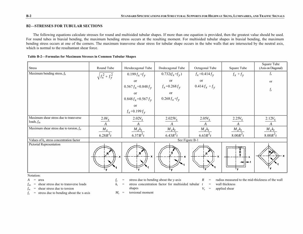
B2—STRESSES FOR TUBULAR SECTIONS The following equations calculate stresses for round and multisided tubular shapes. If more than one equation is provided, then the greatest value should be used.
For round tubes in biaxial bending, the maximum bending stress occurs at the resulting moment. For multisided tubular shapes in biaxial bending, the maximum bending stress occurs at one of the corners. The maximum transverse shear stress for tubular shape occurs in the tube walls that are intersected by the neutral axis, which is normal to the resultantant shear force.
Table B-2—Formulas for Maximum Stresses in Common Tubular Shapes
Stress Round Tube Hexdecagonal Tube Dodecagonal Tube Octagonal Tube Square Tube Square Tube
(Axis on Diagonal) Maximum bending stress, fb 2 2
x yf f+ 0.199 +
or0.567 +0.848
or0.848 +0.567
or +0.199
x y
x y
x y
x y
f f
f f
f f
f f
0.732( + )
or+0.268
or0.268 +
x y
x y
x y
f f
f f
f f
+0.414
or0.414 +
x y
x y
f f
f f
+ x yf f fx
or
fy
Maximum shear stress due to transverse loads, fvb
2.0 sVA
2.02 sV
A
2.025 sVA
2.05 sV
A
2.25 sVA
2.12 sV
A
Maximum shear stress due to torsion, fvt 26.28
zM
R t 26.37
z tM k
R t 26.43
z tM k
R t 26.63
z tM k
R t 28.00
z tM k
R t 28.00
z tM k
R t
Values of kt, stress concentration factor See Figure B-1 Pictorial Representation
Notation: A = area fvb = shear stress due to transverse loads fvt = shear stress due to torsion fx = stress due to bending about the x-axis
fy = stress due to bending about the y-axis kt = stress concentration factor for multisided tubular
shapes Mz = torsional moment
R = radius measured to the mid-thickness of the wall t = wall thickness Vs = applied shear
APPENDIX B: DESIGN AIDS B-3
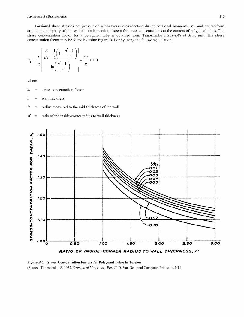
Torsional shear stresses are present on a transverse cross-section due to torsional moments, Mz, and are uniform around the periphery of thin-walled tubular section, except for stress concentrations at the corners of polygonal tubes. The stress concentration factor for a polygonal tube is obtained from Timoshenko’s Strength of Materials. The stress concentration factor may be found by using Figure B-1 or by using the following equation:
1 1
12 1.0
1ln
R nt n tn t nk
nR Rn
t
′ +− + ′′ ′
= + ≥′ +
′
⎡ ⎛ ⎞ ⎤⎜ ⎟⎢ ⎥⎝ ⎠⎢ ⎥
⎛ ⎞⎢ ⎥⎜ ⎟⎣ ⎦⎝ ⎠
where:
kt = stress concentration factor
t = wall thickness
R = radius measured to the mid-thickness of the wall
n′ = ratio of the inside-corner radius to wall thickness
Figure B-1—Stress-Concentration Factors for Polygonal Tubes in Torsion (Source: Timoshenko, S. 1957. Strength of Materials—Part II. D. Van Nostrand Company, Princeton, NJ.)

B-4 STANDARD SPECIFICATIONS FOR STRUCTURAL SUPPORTS FOR HIGHWAY SIGNS, LUMINAIRES, AND TRAFFIC SIGNALS
B3—DEFLECTION EQUATIONS FOR TAPERED TUBULAR CANTILEVERED BEAMS
Equations to compute deflections of prismatic beams are not applicable for tapered beams. Table B-3 provides equations to compute deflection and slope at the tip of tubular cantilever tapered beams. Equations provided in Table B-3 are valid only when the wall thickness t is very small in comparison with the mean radius R of the cross-section. Table B-3—Estimated Maximum Deflection and Slope of Tapered Hollow Beams
Transverse Point Load at Tip of Beam
( )
3
max 3 2 ln 32
B B A A
A B BB A
R R R RWLyR R RECt R R
⎡ ⎤⎛ ⎞ ⎛ ⎞⎛ ⎞−= − −⎢ ⎥⎜ ⎟ ⎜ ⎟⎜ ⎟
⎢ ⎥− ⎝ ⎠ ⎝ ⎠⎝ ⎠⎣ ⎦
2
max 2θ2 A B
WLECtR R
=
End Moment Applied at Tip of Beam
( )2
max 22 A B
MLyECt R R
=
( )
max 2 2θ2
A B
A B
ML R RECtR R
+=
Uniform Load
( )
23
max 4 213 ln262
B A AA B
A B BB A
R R RWLy R RR R RECt R R
⎡ ⎤⎛ ⎞⎛ ⎞= − − + + +⎢ ⎥⎜ ⎟⎜ ⎟⎜ ⎟− ⎢ ⎥⎝ ⎠⎝ ⎠⎣ ⎦
( )( )
2
max 3 23θ ln 4222
B AB A
A BB A
R RWL R RR RECt R R
⎡ ⎤⎛ ⎞= + − −⎢ ⎥⎜ ⎟
⎢ ⎥− ⎝ ⎠⎣ ⎦
W wL= Triangular Load
( )
2 332 2
max 5 28
12 ln 86
B A AA A B B
A B BB A
R R RWLy R R R RR R RECt R R
⎡ ⎤⎛ ⎞⎛ ⎞= + − − +⎢ ⎥⎜ ⎟⎜ ⎟ ⎜ ⎟− ⎢ ⎥⎝ ⎠ ⎝ ⎠⎣ ⎦
( )
22
max 4 21θ ln2 36
B A A BA
A B BB A
R R R RWL RR R RECt R R
⎡ ⎤⎛ ⎞⎛ ⎞= − − + − +⎢ ⎥⎜ ⎟⎜ ⎟⎜ ⎟− ⎢ ⎥⎝ ⎠⎝ ⎠⎣ ⎦
2wLW =
Notation:
C = cross-sectional constant defined per Table B-1
E = modulus of elasticity
L = length of the beam (from ground line to tip)
M = applied moment
RA = radius measured to mid-thickness of wall at free end (see Table B-1)
RB = radius measured to mid-thickness of wall at fixed end (see Table B-1)
t = wall thickness
W = load
w = load per unit length
ymax = maximum horizontal deflection at free end of beam
θmax = maximum slope at free end of beam (rad)
Note: Equations are based on the small deflection theory; therefore tan θ = θ.
Adapted from: Hopkins, R. B. 1970. Design Analysis of Shafts and Beams. McGraw–Hill, New York, NY.

APPENDIX B: DESIGN AIDS B-5
B4—DEFLECTION EQUATIONS FOR TAPERED CANTILEVERED BEAMS Table B-4 provides equations to compute tip deflections and slope for solid round cantilevered beams, such as wood poles.
Table B-4—Maximum Deflection and Slope of Solid Round Tapered Beams
Slope Deflection Transverse Point Load at Free End
2
max 2.497θ
2.068 ba
a
PL
dEId
=⎛ ⎞⎜ ⎟⎝ ⎠
3
max 3
3 ba
a
PLydEId
=⎛ ⎞⎜ ⎟⎝ ⎠
End Moment Applied at Free End
max 1 587θ
1.075 ba
a
ML
dEId
=⎛ ⎞⎜ ⎟⎝ ⎠
. 2
max 2.497
2.068 ba
a
MLydEId
=⎛ ⎞⎜ ⎟⎝ ⎠
Uniform Load Applied Along Length
3
max 3θ
6 ba
a
wL
dEId
=⎛ ⎞⎜ ⎟⎝ ⎠
4
max 3.282
7.872 ba
a
wLydEId
=⎛ ⎞⎜ ⎟⎝ ⎠
Notation:
da = diameter at free end
db = diameter at fixed end
E = modulus of elasticity
Ia = moment of inertia of cross-section at free end of beam
L = length
M = moment applied at free end of beam
P = horizontal load applied at free end of beam
w = uniformly distributed load applied along the beam length
ymax = deflection at free end of beam
θmax = slope at free end of beam (rad)
Source: Author, Initials. 1985. “Graphs to Determine Structure Deflections,” Transmission and Distribution. July 1985, pp. X–Y.

B-6 STANDARD SPECIFICATIONS FOR STRUCTURAL SUPPORTS FOR HIGHWAY SIGNS, LUMINAIRES, AND TRAFFIC SIGNALS
B5—EFFECTIVE LENGTH FACTORS FOR COLUMNS Table B-5 provides effective length factors for centrally loaded columns with various end conditions.
Table B-5—Effective Length Factors for Centrally Loaded Columns
Buckled Shape of Column Shown by Dashed Line
Theoretical K Value 0.50 0.70 1.00 1.00 2.00 2.00 Recommended Design Values when Ideal Conditions are Approximated 0.65 0.80 1.00 1.20 2.10 2.00
Rotation fixed, Translation fixed
Rotation free, Translation fixed
Rotation fixed, Translation free
End Conditions Code
Rotation free, Translation free

APPENDIX B: DESIGN AIDS B-7
B6—ALLOWABLE STRESSES FOR SELECTED ALUMINUM ALLOYS Tables B-6 through B-11 provide allowable stresses for welded and nonwelded members for A6005-T5, A6061-T6, and A6063-T6.
Table B-6—Allowable Stresses for Aluminum 6005—T5 Alloy (MPa)
Type of Stress Type of Member or Component
Eq. Set Allowable Stress
Tension, axial, net section
Any tension member
6-1 131 72.4 6005—T5 Extrusions Thickness Up Through 25 mm
Rectangular tubes, structural shapes bent around strong axis
6-2 131 72.4 White bars apply to nonwelded members and to welded members at locations farther than 25.4 mm from a weld.
Round or oval tubes
6-3 165 82.7 Shaded bars apply to within 25.4 mm of a weld.
Tension in Beams, extreme fiber, net section
Shapes bent about weak axis, bars, plates
6-4 193 93.1 Notes:
See Articles 6.4.1, 6.4.2.1, and 6.4.4.1 for additional provisions regarding allowable stresses.
For tubes with circumferential welds, R/t and Rb/t, as applicable, shall be ≤20, except when the design meets the details and post-weld heat treatment requirements of Article 6.5.
On bolts 6-5 234 124 See Article 6.5 for additional provisions regarding allowable stresses in welded members.
The article numbers and equations referenced in this table refer to Section 6, “Aluminum Design.”
Bearing
On flat surfaces and on bolts in slotted holes
6-6 159 82.7
Continued on next page

B-8 STANDARD SPECIFICATIONS FOR STRUCTURAL SUPPORTS FOR HIGHWAY SIGNS, LUMINAIRES, AND TRAFFIC SIGNALS
Continued on next page
Table B-6—Allowable Stresses for Aluminum 6005—T5 Alloy (MPa)—Continued
Type of Stress Type of Member or Component
Eq. Set
(a) Allowable Stress Slenderness ≤ S1
(b) Slenderness Limit S1
(c) Allowable Stress Slenderness Between S1 and S2
(d) Slenderness Limit S2
(e) Allowable Stress Slenderness ≥ S2
131 9.5kL
r= 139.3 0.869 kL
r⎛ ⎞− ⎜ ⎟⎝ ⎠
66kLr
= 351600
2kLr
⎛ ⎞⎜ ⎟⎝ ⎠
Compression in Columns, axial, gross section
All columns
6-7
72.4 — 72.4 70kL
r=
3516002kL
r⎛ ⎞⎜ ⎟⎝ ⎠
131 5.2b
t= 159.3 5.45 b
t⎛ ⎞⎜ ⎟⎝ ⎠
− 10bt
= 1062
bt
⎛ ⎞⎜ ⎟⎝ ⎠
Flat plates supported along one edge—columns buckling about a symmetry axis
6-8
72.4 — 72.4 15b
t=
1062bt
⎛ ⎞⎜ ⎟⎝ ⎠
131 5.2b
t= 159.3 5.45 b
t⎛ ⎞⎜ ⎟⎝ ⎠
− 12bt
= 13580
2bt
⎛ ⎞⎜ ⎟⎝ ⎠
Compression in Components of Columns, gross section
Flat plates supported along one edge—columns not buckling about a symmetry axis
6-9
72.4 — 72.4 14b
t=
135802b
t⎛ ⎞⎜ ⎟⎝ ⎠

APPENDIX B: DESIGN AIDS B-9
ibn
Table B-6—Allowable Stresses for Aluminum 6005—T5 Alloy (MPa)—Continued
Continued on next page
Type of Stress Type of Member or Component
Eq. Set
(a) Allowable Stress Slenderness ≤ S1
(b) Slenderness Limit S1
(c) Allowable Stress Slenderness Between S1 and S2
(d) Slenderness Limit S2
(e) Allowable Stress Slenderness ≥ S2
131 16b
t= 159.3 1.72 b
t⎛ ⎞− ⎜ ⎟⎝ ⎠
33bt
= 3378
bt
⎛ ⎞⎜ ⎟⎝ ⎠
Flat plates with both edges supported
6-10
72.4 — 72.4 47b
t=
3378bt
⎛ ⎞⎜ ⎟⎝ ⎠
131 16R
t= 153.1 5.52 R
t− 141R
t=
220602
135
RR tt
⎛ ⎞⎜ ⎟⎛ ⎞⎜ ⎟ + ⎜ ⎟⎜ ⎟⎝ ⎠⎜ ⎟⎝ ⎠
Compression in Components of Columns, gross section
Curved plates supported on both edges, walls of round or oval tubesb
6-11
72.4 5.1R
t= 178.6 2.76 sin θR
t−− 340R
t=
220602
135
RR tt
⎛ ⎞⎜ ⎟⎛ ⎞⎜ ⎟ + ⎜ ⎟⎜ ⎟⎝ ⎠⎜ ⎟⎝ ⎠

B-10 STANDARD SPECIFICATIONS FOR STRUCTURAL SUPPORTS FOR HIGHWAY SIGNS, LUMINAIRES, AND TRAFFIC SIGNALS
Table B-6—Allowable Stresses for Aluminum 6005—T5 Alloy (MPa)—Continued
Type of Stress Type of Member or Component
Eq. Set
(a) Allowable Stress
Slenderness ≤ S1 (b) Slenderness Limit S1
(c) Allowable Stress Slenderness Between
S1 and S2 (d) Slenderness Limit S2
(e) Allowable Stress Slenderness ≥ S2
145 23b
y
Lr = 164.8 0.855 Lb
r y− 79Lb
r y= 2
600000
by
Lr
⎛ ⎞⎜ ⎟⎜ ⎟⎝ ⎠
Single web beams bent about strong axis
6-12
72.4 —
72.4 91Lb
r y=
2600000
by
Lr
⎛ ⎞⎜ ⎟⎜ ⎟⎝ ⎠
172 28Rb
t= 271.0 18.62 Rb
t− 81Rb
t=
same as Eq. 6-11 with R = Rb Round or oval tubesb
6-13
82.7 53Rb
t= 128.2 6.89 Rb
t− 134Rb
t=
same as Eq. 6-11 with R = Rb
193 13bLd
t d= 279.2 6.41 bLd
t d− 29d Lb
t d= 2
78600
bLdt d
⎛ ⎞⎛ ⎞⎜ ⎟ ⎜ ⎟⎝ ⎠ ⎝ ⎠
Solid rectangular and round section beams
6-14
93.1 — 93.1 29d Lb
t d= 2
78600
bLdt d
⎛ ⎞⎛ ⎞⎜ ⎟ ⎜ ⎟⎝ ⎠ ⎝ ⎠
145 146
0.5L Sb c
I Jy= 164.8 1.66
0.5b c
y
L SL J
− 17000.5
b c
y
L SL J
= 165500
0.5b c
y
L SI J
⎛ ⎞⎜ ⎟⎜ ⎟⎝ ⎠
Compression in Beams, extreme fiber, gross section
Rectangular tubes and box sections
6-15
72.4 — 72.4 2290
0.5b c
y
L SI J
= 165500
0.5b c
y
L SI J
⎛ ⎞⎜ ⎟⎜ ⎟⎝ ⎠
Continued on next page
t
APPENDIX B: DESIGN AIDS B-11
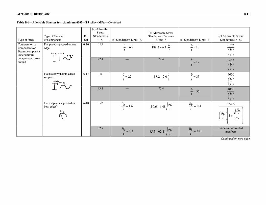
Table B-6—Allowable Stresses for Aluminum 6005—T5 Alloy (MPa)—Continued
Type of Stress Type of Member or Component
Eq. Set
(a) Allowable Stress
Slenderness ≤ S1 (b) Slenderness Limit S1
(c) Allowable Stress Slenderness Between
S1 and S2 (d) Slenderness Limit S2 (e) Allowable Stress
Slenderness ≥ S2 145
6.8bt
= 188.2 6.41bt
− 10bt
= 1262
bt
⎛ ⎞⎜ ⎟⎝ ⎠
Flat plates supported on one edge
6-16
72.4 — 72.4 17b
t=
1262bt
⎛ ⎞⎜ ⎟⎝ ⎠
145 22b
t= 188.2 2.0 b
t− 33b
t=
4000bt
⎛ ⎞⎜ ⎟⎝ ⎠
Compression in Components of Beams, component under uniform compression, gross section
Flat plates with both edges supported
6-17
93.1 — 72.4 55b
t=
4000bt
⎛ ⎞⎜ ⎟⎝ ⎠
172 1.6bR
t= 180.6 6.48 bR
t− 141bR
t=
26200
135
bb
RR tt
⎛ ⎞⎜ ⎟⎛ ⎞⎜ ⎟+⎜ ⎟⎜ ⎟⎝ ⎠⎜ ⎟⎝ ⎠
Curved plates supported on
both edgesb
6-18
82.7 1.3bR
t= 85.5 02.41 bR
t− 340bR
t=
Same as nonwelded members
Continued on next page

B-12 STANDARD SPECIFICATIONS FOR STRUCTURAL SUPPORTS FOR HIGHWAY SIGNS, LUMINAIRES, AND TRAFFIC SIGNALS
Table B-6—Allowable Stresses for Aluminum 6005—T5 Alloy (MPa)—Continued
Type of Stress Type of Member or Component
Eq. Set
(a) Allowable Stress
Slenderness ≤ S1 (b) Slenderness Limit S1
(c) Allowable Stress Slenderness Between
S1 and S2 (d) Slenderness Limit S2
(e) Allowable Stress Slenderness ≥ S2
193 8.9b
t= 279.2 9.72 b
t− 19b
t= 2
33780
bt
⎛ ⎞⎜ ⎟⎝ ⎠
Flat plates with compression edge free, tension edge supported
6-19
93.1 — 93.1 19b
t= 2
33780
bt
⎛ ⎞⎜ ⎟⎝ ⎠
193 46h
t= 279.2 1.86 h
t− 75h
t=
10480ht
⎛ ⎞⎜ ⎟⎝ ⎠
Compression in Components of Beams, component under bending in own plane, gross section
Flat plate with both edges supported
6-20
93.1 — 93.1 113h
t=
10480ht
⎛ ⎞⎜ ⎟⎝ ⎠
83 36h
t= 107.6 0.683 h
t− 65h
t= 2
268900
ht
⎛ ⎞⎜ ⎟⎝ ⎠
Shear in Webs, gross section
Unstiffened flat webs
6-21
41.4 — 41.4 81h
t= 2
268900
ht
⎛ ⎞⎜ ⎟⎝ ⎠

APPENDIX B: DESIGN AIDS B-13
Table B-7—Allowable Stresses for Aluminum 6005—T5 Alloy (ksi)
Type of Stress Type of Member or Component
Eq. Set Allowable Stress
Tension, axial, net section
Any tension member
6-1 19 10.5 6005—T5 Extrusions Thickness ≤1.0 in
Rectangular tubes, structural shapes bent around strong axis
6-2 19 10.5 White bars apply to nonwelded members and to welded members at locations farther than 1.0 in from a weld.
Round or oval tubes
6-3 24 12 Shaded bars apply to within 1.0 in of a weld.
Tension in Beams, extreme fiber, net section
Shapes bent about weak axis, bars, plates
6-4 28 13.5
On bolts
6-5 34 18 Bearing
On flat surfaces and on bolts in slotted holes
6-6 23 12
Notes: a See Articles 6.4.1, 6.4.2.1, and 6.4.4.1 for additional provisions regarding
allowable stresses. b For tubes with circumferential welds, R/t and Rb/t, as applicable, shall be ≤20,
except when the design meets the details and post-weld heat treatment requirements of Article 6.5.
c See Article 6.5 for additional provisions regarding allowable stresses in welded members.
d The article numbers and equations referenced in this table refer to Section 6, “Aluminum Design.”
Continued on next page

B-14 STANDARD SPECIFICATIONS FOR STRUCTURAL SUPPORTS FOR HIGHWAY SIGNS, LUMINAIRES, AND TRAFFIC SIGNALS
Table B-7—Allowable Stresses for Aluminum 6005—T5 Alloy (ksi)—Continued
Type of Stress Type of Member or Component
Eq. Set
(a) Allowable Stress
Slenderness ≤ S1 (b) Slenderness Limit S1
(c) Allowable Stress Slenderness Between
S1 and S2 (d) Slenderness Limit S2 (e) Allowable Stress
Slenderness ≥ S2 19
9.5kLr
= 20.2 0.126 kLr
⎛ ⎞− ⎜ ⎟⎝ ⎠
66kLr
= 251000
kLr
⎛ ⎞⎜ ⎟⎝ ⎠
Compression in Columns, axial, gross section
All columns
6-7
10.5 — 10.5 70kL
r= 2
51000
kLr
⎛ ⎞⎜ ⎟⎝ ⎠
19 5.2b
t= 23.1 0.79 b
t⎛ ⎞− ⎜ ⎟⎝ ⎠
10bt
= 154
bt
⎛ ⎞⎜ ⎟⎝ ⎠
Flat plates supported along one edge—columns buckling about a symmetry axis
6-8
10.5 — 10.5 15b
t=
154bt
⎛ ⎞⎜ ⎟⎝ ⎠
19 5.2b
t= 23.1 0.79 b
t⎛ ⎞− ⎜ ⎟⎝ ⎠
12bt
= 21970
bt
⎛ ⎞⎜ ⎟⎝ ⎠
Flat plates supported along one edge—columns not buckling about a symmetry axis
6-9
10.5 — 10.5
14bt
= 21970
bt
⎛ ⎞⎜ ⎟⎝ ⎠
19 16b
t= 23.1 0.25 b
t⎛ ⎞− ⎜ ⎟⎝ ⎠
33bt
= 490bt
⎛ ⎞⎜ ⎟⎝ ⎠
Compression in Components of Columns, gross section
Flat plates with both edges supported
6-10
10.5 — 10.5 47b
t=
490bt
⎛ ⎞⎜ ⎟⎝ ⎠
Continued on next page
APPENDIX B: DESIGN AIDS B-15
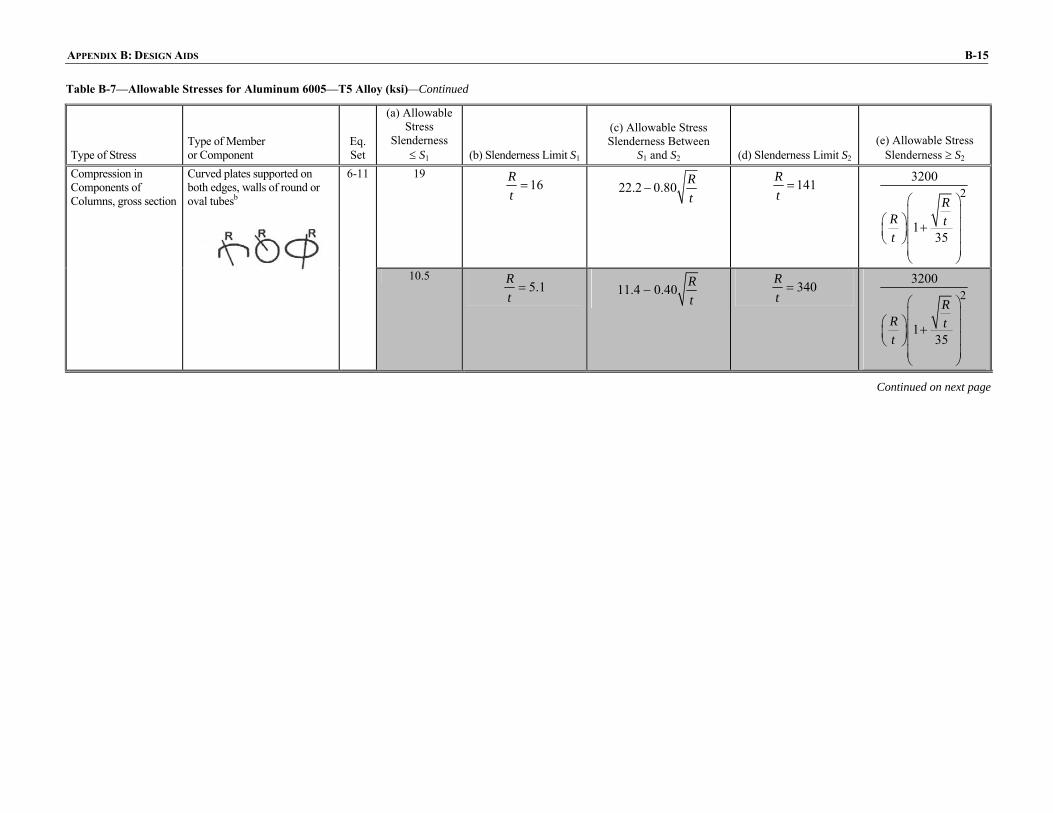
Table B-7—Allowable Stresses for Aluminum 6005—T5 Alloy (ksi)—Continued
Type of Stress Type of Member or Component
Eq. Set
(a) Allowable Stress
Slenderness ≤ S1 (b) Slenderness Limit S1
(c) Allowable Stress Slenderness Between
S1 and S2 (d) Slenderness Limit S2 (e) Allowable Stress
Slenderness ≥ S2 19
16Rt
= 22.2 0.80 Rt
− 141Rt
= 23200
135
RR tt
⎛ ⎞⎜ ⎟⎛ ⎞⎜ ⎟+⎜ ⎟⎜ ⎟⎝ ⎠⎜ ⎟⎝ ⎠
Compression in Components of Columns, gross section
Curved plates supported on both edges, walls of round or oval tubesb
6-11
10.5 5.1R
t= 11.4 0.40 R
t− 340R
t= 2
3200
135
RR tt
⎛ ⎞⎜ ⎟⎛ ⎞⎜ ⎟+⎜ ⎟⎜ ⎟⎝ ⎠⎜ ⎟⎝ ⎠
Continued on next page
B-16 STANDARD SPECIFICATIONS FOR STRUCTURAL SUPPORTS FOR HIGHWAY SIGNS, LUMINAIRES, AND TRAFFIC SIGNALS
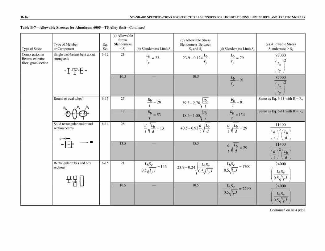
Table B-7—Allowable Stresses for Aluminum 6005—T5 Alloy (ksi)—Continued
Type of Stress Type of Member or Component
Eq. Set
(a) Allowable Stress
Slenderness ≤ S1 (b) Slenderness Limit S1
(c) Allowable Stress Slenderness Between
S1 and S2 (d) Slenderness Limit S2
(e) Allowable Stress Slenderness ≥ S2
21 23b
y
Lr
= 23.9 0.124 by
Lr
− 79by
Lr
= 287000
by
Lr
⎛ ⎞⎜ ⎟⎜ ⎟⎝ ⎠
Single web beams bent about strong axis
6-12
10.5 — 10.5 91b
y
Lr
= 2
87000
by
Lr
⎛ ⎞⎜ ⎟⎜ ⎟⎝ ⎠
25 28bR
t= 39.3 2.70 bR
t− 81bR
t=
Same as Eq. 6-11 with R = Rb
Round or oval tubesb
6-13
12 53bR
t= 18.6 1.00 bR
t− 134bR
t=
Same as Eq. 6-11 with R = Rb
28 13bLd
t d= 40.5 0.93 bLd
t d− 29bLd
t d= 2
11400
bLdt d
⎛ ⎞⎛ ⎞⎜ ⎟ ⎜ ⎟⎝ ⎠ ⎝ ⎠
Solid rectangular and round section beams
6-14
13.5 — 13.5 29bLd
t d= 2
11400
bLdt d
⎛ ⎞⎛ ⎞⎜ ⎟ ⎜ ⎟⎝ ⎠ ⎝ ⎠
21 146
0.5b c
y
L SI J
= 23.9 0.240.5
b c
y
L SI J
− 17000.5
b c
y
L Sl J
= 24000
0.5b c
y
L Sl J
⎛ ⎞⎜ ⎟⎜ ⎟⎝ ⎠
Compression in Beams, extreme fiber, gross section
Rectangular tubes and box sections
6-15
10.5 — 10.5 2290
0.5b c
y
L Sl J
= 24000
0.5b c
y
L Sl J
⎛ ⎞⎜ ⎟⎜ ⎟⎝ ⎠
Continued on next page
t

APPENDIX B: DESIGN AIDS B-17
Table B-7—Allowable Stresses for Aluminum 6005—T5 Alloy (ksi)—Continued
Type of Stress Type of Member or Component
Eq. Set
(a) Allowable Stress
Slenderness ≤ S1 (b) Slenderness Limit S1
(c) Allowable Stress Slenderness Between S1 and
S2 (d) Slenderness Limit S2 (e) Allowable Stress
Slenderness ≥ S2 21
6.8bt
= 27.3 0.93 bt
− 10bt
= 183
bt
⎛ ⎞⎜ ⎟⎝ ⎠
Flat plates supported on one edge
6-16
10.5 — 10.5 17b
t=
183bt
⎛ ⎞⎜ ⎟⎝ ⎠
21 22b
t= 27.3 0.29 b
t− 33b
t=
580bt
⎛ ⎞⎜ ⎟⎝ ⎠
Flat plates with both edges supported
6-17
13.5 — 10.5 55b
t=
580bt
⎛ ⎞⎜ ⎟⎝ ⎠
25 1.6bR
t= 26.2 0.94 bR
t− 141bR
t= 2
3800
135
bb
RR tt
⎛ ⎞⎜ ⎟⎛ ⎞⎜ ⎟+⎜ ⎟⎜ ⎟⎝ ⎠⎜ ⎟⎝ ⎠
Compression in Components of Beams, component under uniform compression, gross section
Curved plates supported on both edgesb
6-18
12 1.3bR
t= 12.4 0.35 bR
t− 340bR
t=
Same as nonwelded members
Continued on next page

B-18 STANDARD SPECIFICATIONS FOR STRUCTURAL SUPPORTS FOR HIGHWAY SIGNS, LUMINAIRES, AND TRAFFIC SIGNALS
Table B-7—Allowable Stresses for Aluminum 6005—T5 Alloy (ksi)—Continued
Type of Stress Type of Member or Component
Eq. Set
(a) Allowable Stress
Slenderness ≤ S1 (b) Slenderness Limit S1
(c) Allowable Stress Slenderness Between
S1 and S2 (d) Slenderness Limit S2 (e) Allowable Stress
Slenderness ≥ S2 28
8.9bt
= 40.5 1.41bt
− 19bt
= 24900
bt
⎛ ⎞⎜ ⎟⎝ ⎠
Flat plates with compression edge free, tension edge supported
6-19
13.5 — 13.5 19b
t= 2
4900
bt
⎛ ⎞⎜ ⎟⎝ ⎠
28 46h
t= 40.5 0.27 h
t− 75h
t=
1520ht
⎛ ⎞⎜ ⎟⎝ ⎠
Compression in Components of Beams, component under bending in own plane, gross section
Flat plate with both edges supported
6-20
13.5 — 13.5 113h
t=
1520ht
⎛ ⎞⎜ ⎟⎝ ⎠
12 36h
t= 15.6 0.099 h
t− 65h
t= 2
39000
ht
⎛ ⎞⎜ ⎟⎝ ⎠
Shear in Webs, gross section
Unstiffened flat webs
6-21
6 — 6 81h
t= 2
39000
ht
⎛ ⎞⎜ ⎟⎝ ⎠

APPENDIX B: DESIGN AIDS B-19
Table B-8—Allowable Stresses for Aluminum 6061—T6 Alloy (MPa)
Type of Stress Type of Member or Component
Eq. Set Allowable Stress
Tension, axial, net section
Any tension member
6-1 131 75.8† 6061—T6 Extrusions Up Through 25 mm, Sheet and Plate, Standard Structural Shapes, Drawn Tube, Rolled Rod and Bar
Rectangular tubes, structural shapes bent around strong axis
6-2 131 75.8† White bars apply to nonwelded members and to welded members at locations farther than 25 mm from a weld
Round or oval tubes
6-3 165 93† Shaded bars apply to within 25 mm of a weld
Tension in Beams, extreme fiber, net section
Shapes bent about weak axis, bars, plates
6-4 193 110†
On bolts
6-5 234 124† Bearing
On flat surfaces and on bolts in slotted holes
6-6 159 82.7†
Notes: a See Articles 6.4.1, 6.4.2.1, and 6.4.4.1 for additional provisions regarding
allowable stresses. b For tubes with circumferential welds, R/t and Rb/t, as applicable, shall be ≤20,
except when the design meets the details and post-weld heat treatment requirements of Article 6.5
c See Article 6.5 for additional provision regarding allowable stresses in welded members.
d The article numbers and equations referenced in this table refer to Section 6, “Aluminum Design.”
† Values when welded with 5183, 5356, or 5556 alloy filler wire, regardless of thickness. Values also apply to thicknesses ≤9.5 mm when welded with 4043 alloy filler wire; for greater thicknesses multiply allowable tensile stresses by 0.8 and allowable compressive and shear stresses by 0.75.
‡ For all thicknesses with filler alloys 5183, 5356 or 5556; and for thicknesses ≤9.5 mm for 4043 filler alloy.
Continued on next page

B-20 STANDARD SPECIFICATIONS FOR STRUCTURAL SUPPORTS FOR HIGHWAY SIGNS, LUMINAIRES, AND TRAFFIC SIGNALS
Continued on next page
Table B-8—Allowable Stresses for Aluminum 6061—T6 Alloy (MPa)—Continued
Type of Stress Type of Member or Component
Eq. Set
(a) Allowable Stress
Slenderness ≤ S1 (b) Slenderness
Limit S1
(c) Allowable Stress Slenderness Between
S1 and S2 (d) Slenderness Limit
S2 (e) Allowable Stress
Slenderness ≥ S2 6-7 131
9.5kLr
= 139.3 0.869 kLr
⎛ ⎞− ⎜ ⎟⎝ ⎠
66kLr
= 2351600
kLr
⎛ ⎞⎜ ⎟⎝ ⎠
Compression in Columns, axial, gross section
All columns
82.7† — 82.7† 65kLr
= ‡ 2351600
kLr
⎛ ⎞⎜ ⎟⎝ ⎠
6-8 131 5.2b
t= 159.3 5.45 b
t⎛ ⎞− ⎜ ⎟⎝ ⎠
10bt
= 1062
bt
⎛ ⎞⎜ ⎟⎝ ⎠
Flat plates supported along one edge—columns buckling about a symmetry axis
82.7† — 82.7†
13bt
= ‡ 1062
bt
⎛ ⎞⎜ ⎟⎝ ⎠
6-9 131 5.2b
t= 159.3 5.45 b
t⎛ ⎞− ⎜ ⎟⎝ ⎠
12bt
= 213580
bt
⎛ ⎞⎜ ⎟⎝ ⎠
Flat plates supported along one edge—columns not buckling about a symmetry axis
82.7† — 82.7† 13b
t= ‡ 2
13580
bt
⎛ ⎞⎜ ⎟⎝ ⎠
6-10 131 16b
t= 159.3 1.72 b
t⎛ ⎞− ⎜ ⎟⎝ ⎠
33bt
= 3378
bt
⎛ ⎞⎜ ⎟⎝ ⎠
Compression in Components of Columns, gross section
Flat plates with both edges supported
82.7† — 82.7† 41b
t= ‡
3378bt
⎛ ⎞⎜ ⎟⎝ ⎠

APPENDIX B: DESIGN AIDS B-21
Table B-8—Allowable Stresses for Aluminum 6061—T6 Alloy (MPa)—Continued
Type of Stress Type of Member or Component
Eq. Set
(a) Allowable Stress
Slenderness ≤ S1 (b) Slenderness
Limit S1
(c) Allowable Stress Slenderness Between
S1 and S2 (d) Slenderness Limit
S2 (e) Allowable Stress
Slenderness ≥ S2 131
16Rt
= 153.1 5.52 Rt
− 141Rt
= 222060
135
RR tt
⎛ ⎞⎜ ⎟⎛ ⎞⎜ ⎟+⎜ ⎟⎜ ⎟⎝ ⎠⎜ ⎟⎝ ⎠
Compression in Components of Columns, gross section
Curved plates supported on both edges, walls of round or oval tubesb
6-11
82.7† 9.0R
t= 93.1 3.45 R
t− 290R
t= 2
22060
135
RR tt
⎛ ⎞⎜ ⎟⎛ ⎞⎜ ⎟+⎜ ⎟⎜ ⎟⎝ ⎠⎜ ⎟⎝ ⎠
145 23b
y
Lr
= 164.8 0.855 by
Lr
− 79by
Lr
= 2
600000
by
Lr
⎛ ⎞⎜ ⎟⎜ ⎟⎝ ⎠
Single web beams bent about strong axis
6-12
82.7† — 82.7† 85by
Lr
= ‡ 2600000
by
Lr
⎛ ⎞⎜ ⎟⎜ ⎟⎝ ⎠
172 28bR
t= 270.6 18.61 bR
t− 81bR
t=
Same as Eq. 6-11 with R = Rb
Compression in Beams, extreme fiber, gross section
Round or oval tubesb
6-13
96.5† 51bR
t= 164.8 9.58 bR
t− 137bR
t=
Same as Eq. 6-11 with R = Rb
Continued on next page
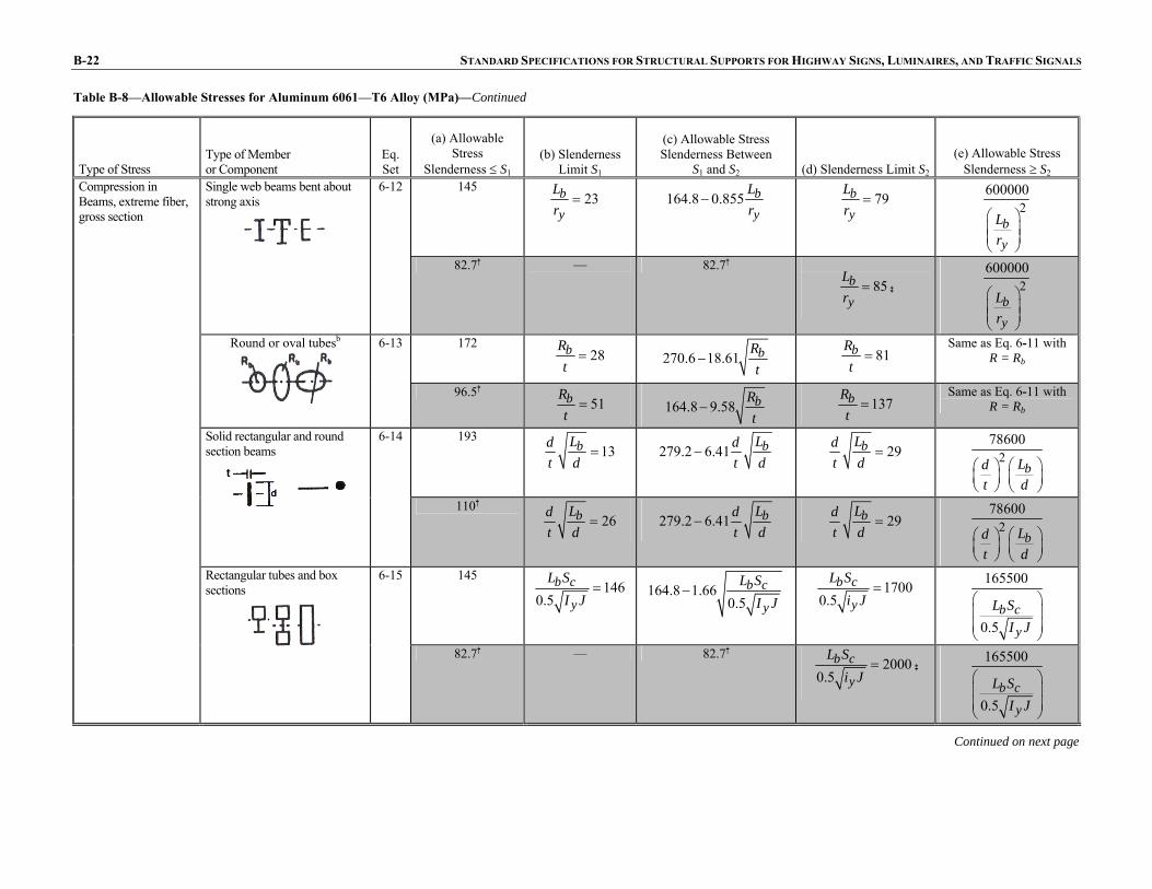
B-22 STANDARD SPECIFICATIONS FOR STRUCTURAL SUPPORTS FOR HIGHWAY SIGNS, LUMINAIRES, AND TRAFFIC SIGNALS
Table B-8—Allowable Stresses for Aluminum 6061—T6 Alloy (MPa)—Continued
Type of Stress Type of Member or Component
Eq. Set
(a) Allowable Stress
Slenderness ≤ S1 (b) Slenderness
Limit S1
(c) Allowable Stress Slenderness Between
S1 and S2 (d) Slenderness Limit S2
(e) Allowable Stress Slenderness ≥ S2
6-12 145 23b
y
Lr
= 164.8 0.855 by
Lr
− 79by
Lr
= 2600000
by
Lr
⎛ ⎞⎜ ⎟⎜ ⎟⎝ ⎠
Single web beams bent about strong axis
82.7† — 82.7†
85by
Lr
= ‡ 2600000
by
Lr
⎛ ⎞⎜ ⎟⎜ ⎟⎝ ⎠
6-13 172 28bR
t= 270.6 18.61 bR
t− 81bR
t=
Same as Eq. 6-11 with R = Rb
Round or oval tubesb
96.5† 51bR
t= 164.8 9.58 bR
t− 137bR
t=
Same as Eq. 6-11 with R = Rb
6-14 193 13bLd
t d= 279.2 6.41 bLd
t d− 29bLd
t d= 2
78600
bLdt d
⎛ ⎞⎛ ⎞⎜ ⎟ ⎜ ⎟⎝ ⎠ ⎝ ⎠
Solid rectangular and round section beams
110† 26bLd
t d= 279.2 6.41 bLd
t d− 29bLd
t d= 2
78600
bLdt d
⎛ ⎞⎛ ⎞⎜ ⎟ ⎜ ⎟⎝ ⎠ ⎝ ⎠
6-15 145 146
0.5b c
y
L SI J
= 164.8 1.660.5
b c
y
L SI J
− 17000.5
b c
y
L Si J
= 165500
0.5b c
y
L SI J
⎛ ⎞⎜ ⎟⎜ ⎟⎝ ⎠
Compression in Beams, extreme fiber, gross section
Rectangular tubes and box sections
82.7† — 82.7† 2000
0.5b c
y
L Si J
= ‡ 165500
0.5b c
y
L SI J
⎛ ⎞⎜ ⎟⎜ ⎟⎝ ⎠
Continued on next page
t

APPENDIX B: DESIGN AIDS B-23
Table B-8—Allowable Stresses for Aluminum 6061—T6 Alloy (MPa)—Continued
Type of Stress Type of Member or Component
Eq. Set
(a) Allowable Stress
Slenderness ≤ S1 (b) Slenderness
Limit S1
(c) Allowable Stress Slenderness Between
S1 and S2 (d) Slenderness Limit S2
(e) Allowable Stress Slenderness ≥ S2
6-16 145 6.8b
t= 188.2 6.41b
t− 10b
t=
1255bt
⎛ ⎞⎜ ⎟⎝ ⎠
Flat plates supported on one edge
82.7† — 82.7†
15bt
= ‡ 1255
bt
⎛ ⎞⎜ ⎟⎝ ⎠
6-17 145 22b
t= 188.2 2.0 b
t− 33b
t=
4000bt
⎛ ⎞⎜ ⎟⎝ ⎠
Flat plates with both edges supported
82.7† — 82.7† 48b
t= ‡
4000bt
⎛ ⎞⎜ ⎟⎝ ⎠
6-18 172 1.6bR
t= 180.6 6.48 bR
t− 141bR
t= 2
26200
135
bb
RR tt
⎛ ⎞⎜ ⎟⎛ ⎞⎜ ⎟+⎜ ⎟⎜ ⎟⎝ ⎠⎜ ⎟⎝ ⎠
Compression in Components of Beams, component under uniform compression, gross section
Curved plates supported on both edgesb
96.5† 2.5bR
t= 101.4 3.03 bR
t− 290bR
t=
Same as nonwelded members
Continued on next page
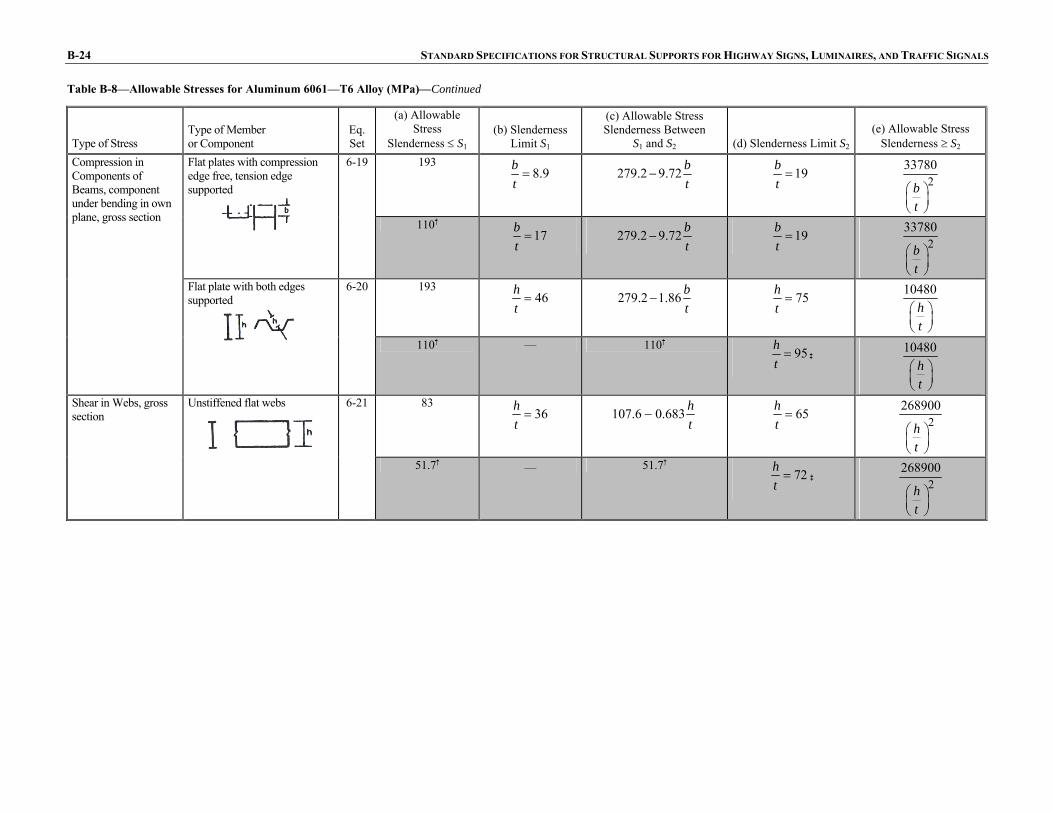
B-24 STANDARD SPECIFICATIONS FOR STRUCTURAL SUPPORTS FOR HIGHWAY SIGNS, LUMINAIRES, AND TRAFFIC SIGNALS
Table B-8—Allowable Stresses for Aluminum 6061—T6 Alloy (MPa)—Continued
Type of Stress Type of Member or Component
Eq. Set
(a) Allowable Stress
Slenderness ≤ S1 (b) Slenderness
Limit S1
(c) Allowable Stress Slenderness Between
S1 and S2 (d) Slenderness Limit S2
(e) Allowable Stress Slenderness ≥ S2
6-19 193 8.9b
t= 279.2 9.72 b
t− 19b
t= 2
33780
bt
⎛ ⎞⎜ ⎟⎝ ⎠
Flat plates with compression edge free, tension edge supported
110† 17b
t= 279.2 9.72 b
t− 19b
t= 2
33780
bt
⎛ ⎞⎜ ⎟⎝ ⎠
6-20 193 46h
t= 279.2 1.86 b
t− 75h
t=
10480ht
⎛ ⎞⎜ ⎟⎝ ⎠
Compression in Components of Beams, component under bending in own plane, gross section
Flat plate with both edges supported
110† — 110† 95h
t= ‡
10480ht
⎛ ⎞⎜ ⎟⎝ ⎠
6-21 83 36h
t= 107.6 0.683 h
t− 65h
t= 2
268900
ht
⎛ ⎞⎜ ⎟⎝ ⎠
Shear in Webs, gross section
Unstiffened flat webs
51.7† — 51.7†
72ht
= ‡ 2268900
ht
⎛ ⎞⎜ ⎟⎝ ⎠

APPENDIX B: DESIGN AIDS B-25
Table B-9—Allowable Stresses for Aluminum 6061—T6 Alloy (ksi)
Type of Stress Type of Member or Component
Eq. Set Allowable Stress
Tension, axial, net section
Any tension member
6-1 19 11†
Rectangular tubes, structural shapes bent around strong axis
6-2 19 11†
Round or oval tubes
6-3 24 13.5†
6061—T6 Extrusions Up Through 1.0 in, Sheet and Plate, Standard Structural Shapes, Drawn Tube, Rolled Rod and Bar White bars apply to nonwelded members and to welded members at locations farther than 1.0 in from a weld Shaded bars apply to within 1.0 in of a weld
Tension in Beams, extreme fiber, net section
Shapes bent about weak axis, bars, plates
6-4 28 16†
On bolts
6-5 34 18† Bearing
On flat surfaces and on bolts in slotted holes
6-6 23 12†
Notes: a See Articles 6.4.1, 6.4.2.1, and 6.4.4.1 for additional provisions regarding
allowable stresses. b For tubes with circumferential welds, R/t and Rb/t, as applicable, shall be
≤20, except when the design meets the details and post-weld heat treatment requirements of Article 6.5.
c See Article 6.5 for additional provisions regarding allowable stresses in welded members.
d The article numbers and equations referenced in this table refer to Section 6, “Aluminum Design.”
e Values when welded with 5183, 5356, or 5556 alloy filler wire, regardless of thickness. Values also apply to thicknesses ≤0.375 in. when welded with 4043 alloy filler wire; for greater thicknesses multiply allowable tensile stresses by 0.8 and allowable compressive and shear stresses by 0.75.
f For all thicknesses with filler alloys 5183, 5356 or 5556 and for thicknesses ≤0.375 in. for 4043 filler alloy.
Continued on next page

B-26 STANDARD SPECIFICATIONS FOR STRUCTURAL SUPPORTS FOR HIGHWAY SIGNS, LUMINAIRES, AND TRAFFIC SIGNALS
Table B-9—Allowable Stresses for Aluminum 6061—T6 Alloy (ksi)—Continued
Type of Stress Type of Member or Component
Eq. Set
(a) Allowable Stress
Slenderness ≤ S1 (b) Slenderness Limit S1
(c) Allowable Stress Slenderness Between
S1 and S2 (d) Slenderness Limit S2 (e) Allowable Stress
Slenderness ≥ S2 19
9.5kLr
= 20.2 0.126 kLr
⎛ ⎞− ⎜ ⎟⎝ ⎠
66kLr
= 251000
kLr
⎛ ⎞⎜ ⎟⎝ ⎠
Compression in Columns, axial, gross section
All columns
6-7
12† — 12† 65kL
r= ‡ 2
51000
kLr
⎛ ⎞⎜ ⎟⎝ ⎠
19 5.2b
t= 23.1 0.79 b
t⎛ ⎞− ⎜ ⎟⎝ ⎠
10bt
= 154
bt
⎛ ⎞⎜ ⎟⎝ ⎠
Flat plates supported along one edge—columns buckling about a symmetry axis
6-8
12† — 12† 13b
t= ‡
154bt
⎛ ⎞⎜ ⎟⎝ ⎠
19 5.2b
t= 23.1 1.39 b
t⎛ ⎞− ⎜ ⎟⎝ ⎠
12bt
= 21970
bt
⎛ ⎞⎜ ⎟⎝ ⎠
Flat plates supported along one edge—columns not buckling about a symmetry axis
6-9
12† — 12† 13b
t= ‡ 2
1970
bt
⎛ ⎞⎜ ⎟⎝ ⎠
19 16b
t= 23.1 0.25 b
t⎛ ⎞− ⎜ ⎟⎝ ⎠
33bt
= 490bt
⎛ ⎞⎜ ⎟⎝ ⎠
Compression in Components of Columns, gross section
Flat plates with both edges supported
6-10
12† — 12† 41b
t= ‡
490bt
⎛ ⎞⎜ ⎟⎝ ⎠
Continued on next page

APPENDIX B: DESIGN AIDS B-27
Table B-9—Allowable Stresses for Aluminum 6061—T6 Alloy (ksi)—Continued
Type of Stress Type of Member or Component
Eq. Set
(a) Allowable Stress
Slenderness ≤ S1 (b) Slenderness Limit S1
(c) Allowable Stress Slenderness Between
S1 and S2 (d) Slenderness Limit S2 (e) Allowable Stress
Slenderness ≥ S2 19
16Rt
= 22.2 0.80 Rt
− 141Rt
= 23200
135
RR tt
⎛ ⎞⎜ ⎟⎛ ⎞⎜ ⎟+⎜ ⎟⎜ ⎟⎝ ⎠⎜ ⎟⎝ ⎠
Compression in Components of Columns, gross section
Curved plates supported on both edges, walls of round or oval tubesb
6-11
12† 90R
t= 13.5 0.50 R
t− 290R
t= 2
3200
135
RR tt
⎛ ⎞⎜ ⎟⎛ ⎞⎜ ⎟+⎜ ⎟⎜ ⎟⎝ ⎠⎜ ⎟⎝ ⎠
Continued on next page

B-28 STANDARD SPECIFICATIONS FOR STRUCTURAL SUPPORTS FOR HIGHWAY SIGNS, LUMINAIRES, AND TRAFFIC SIGNALS
Table B-9—Allowable Stresses for Aluminum 6061—T6 Alloy (ksi)—Continued
Type of Stress Type of Member or Component
Eq. Set
(a) Allowable Stress
Slenderness ≤ S1 (b) Slenderness Limit S1
(c) Allowable Stress Slenderness Between
S1 and S2 (d) Slenderness Limit S2 (e) Allowable Stress
Slenderness ≥ S2
21 23by
Lr
= 23.9 0.124 by
Lr
− 79by
Lr
= 2
87000
by
Lr
⎛ ⎞⎜ ⎟⎜ ⎟⎝ ⎠
Single web beams bent about strong axis
6-12
12† — 12† 85by
Lr
= ‡ 287000
by
Lr
⎛ ⎞⎜ ⎟⎜ ⎟⎝ ⎠
25 28bRt
= 39.3 2.70 bRt
− 81bRt
= Same as Eq. 6-11 with
R = Rb Round or oval tubesb
6-13
14† 51bRt
= 23.9 1.39 bRt
− 137bRt
= Same as Eq. 6-11 with
R = Rb
28 13bLd
t d= 40.5 0.93 bLd
t d− 29bLd
t d= 2
11400
bLdt d
⎛ ⎞⎛ ⎞⎜ ⎟ ⎜ ⎟⎝ ⎠ ⎝ ⎠
Solid rectangular and round section beams
6-14
16† 26bLd
t d= 40.5 0.93 bLd
t d− 29bLd
t d= 2
11400
bLdt d
⎛ ⎞⎛ ⎞⎜ ⎟ ⎜ ⎟⎝ ⎠ ⎝ ⎠
21 146
0.5b c
y
L SI J
= 23.9 0.240.5
b c
y
L SI J
− 17000.5
b c
y
L SI J
= 24000
0.5b c
y
L SI J
⎛ ⎞⎜ ⎟⎜ ⎟⎝ ⎠
Compression in Beams, extreme fiber, gross section
Rectangular tubes and box sections
6-15
12† — 12† 20000.5
b c
y
L SI J
= ‡ 24000
0.5b c
y
L SI J
⎛ ⎞⎜ ⎟⎜ ⎟⎝ ⎠
Continued on next page
t
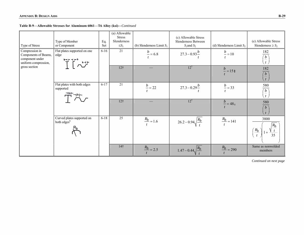
APPENDIX B: DESIGN AIDS B-29
Table B-9—Allowable Stresses for Aluminum 6061—T6 Alloy (ksi)—Continued
Type of Stress Type of Member or Component
Eq. Set
(a) Allowable Stress
Slenderness ≤S1 (b) Slenderness Limit S1
(c) Allowable Stress Slenderness Between
S1and S2 (d) Slenderness Limit S2
(e) Allowable Stress Slenderness ≥ S2
21 6.8b
t= 27.3 0.93 b
t− 10b
t=
182bt
⎛ ⎞⎜ ⎟⎝ ⎠
Flat plates supported on one edge
6-16
12† — 12† 15b
t= ‡
182bt
⎛ ⎞⎜ ⎟⎝ ⎠
21 22b
t= 27.3 0.29 b
t− 33b
t=
580bt
⎛ ⎞⎜ ⎟⎝ ⎠
Flat plates with both edges supported
6-17
12† — 12† 48b
t= ‡
580bt
⎛ ⎞⎜ ⎟⎝ ⎠
25 1.6bR
t= 26.2 0.94 bR
t− 141bR
t=
3800
135
bb
RR tt
⎛ ⎞⎜ ⎟⎛ ⎞⎜ ⎟+⎜ ⎟⎜ ⎟⎝ ⎠⎜ ⎟⎝ ⎠
Compression in Components of Beams, component under uniform compression, gross section
Curved plates supported on both edgesb
6-18
14† 2.5bR
t= 1.47 0.44 bR
t− 290bR
t=
Same as nonwelded members
Continued on next page
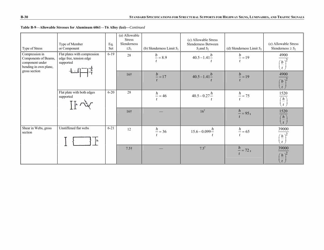
B-30 STANDARD SPECIFICATIONS FOR STRUCTURAL SUPPORTS FOR HIGHWAY SIGNS, LUMINAIRES, AND TRAFFIC SIGNALS
Table B-9—Allowable Stresses for Aluminum 6061—T6 Alloy (ksi)—Continued
Type of Stress Type of Member or Component
Eq. Set
(a) Allowable Stress
Slenderness ≤S1 (b) Slenderness Limit S1
(c) Allowable Stress Slenderness Between
S1and S2 (d) Slenderness Limit S2
(e) Allowable Stress Slenderness ≥ S2
28 8.9bt
= 40.5 1.41bt
− 19bt
= 24900
bt
⎛ ⎞⎜ ⎟⎝ ⎠
Flat plates with compression edge free, tension edge supported
6-19
16† 17bt
= 40.5 1.41bt
− 19bt
= 24900
bt
⎛ ⎞⎜ ⎟⎝ ⎠
28 46h
t= 40.5 0.27 h
t− 75h
t=
1520ht
⎛ ⎞⎜ ⎟⎝ ⎠
Compression in Components of Beams, component under bending in own plane, gross section
Flat plate with both edges supported
6-20
16† — 16† 95ht
= ‡ 1520
ht
⎛ ⎞⎜ ⎟⎝ ⎠
12 36ht
= 15.6 0.099 ht
− 65ht
= 239000
ht
⎛ ⎞⎜ ⎟⎝ ⎠
Shear in Webs, gross section
Unstiffened flat webs
6-21
7.5† — 7.5† 72ht
= ‡ 239000
ht
⎛ ⎞⎜ ⎟⎝ ⎠

APPENDIX B: DESIGN AIDS B-31
Table B-10—Allowable Stresses for Aluminum 6063—T6 Alloy (MPa)
Type of Stress Type of Member or Component
Eq. Set Allowable Stress
Tension, axial, net section
Any tension member
6-1 103 44.8 6063—T6 Extrusions, Pipe
Rectangular tubes, structural shapes bent around strong axis
6-2 103 44.8 White bars apply to nonwelded members and to welded members at locations farther than 25.4 mm from a weld
Round or oval tubes
6-3 124 55.2 Shaded bars apply to within 25.4 mm of a weld
Tension in Beams, extreme fiber, net section
Shapes bent about weak axis, bars, plates
6-4 138 58.6
Bearing On bolts 6-5 165 93.1 On flat surfaces and on bolts in
slotted holes
6-6 110 62.1
Notes: a See Articles 6.4.1, 6.4.2.1, and 6.4.4.1 for additional provisions regarding
allowable stresses. b For tubes with circumferential welds, R/t and Rb/t, as applicable, shall be
≤20, except when the design meets the details and post-weld heat treatment requirements of Article 6.5
c See Article 6.5 for additional provisions regarding allowable stresses in welded members.
d The article numbers and equations referenced in this table refer to Section 6, “Aluminum Design.”
Continued on next page

B-32 STANDARD SPECIFICATIONS FOR STRUCTURAL SUPPORTS FOR HIGHWAY SIGNS, LUMINAIRES, AND TRAFFIC SIGNALS
Table B-10—Allowable Stresses for Aluminum 6063—T6 Alloy (MPa)—Continued
Type of Stress Type of Member or Component
Eq. Set
(a) Allowable Stress
Slenderness ≤ S1
(b) Slenderness Limit S1
(c) Allowable Stress Slenderness Between
S1 and S2 (d) Slenderness Limit
S2 (e) Allowable Stress
Slenderness ≥ S2 93.1
9.5kLr
= 97.9 0.510 kLr
⎛ ⎞− ⎜ ⎟⎝ ⎠
78kLr
= 2351600
kLr
⎛ ⎞⎜ ⎟⎝ ⎠
Compression in Columns, axial, gross section
All columns
6-7
44.8 — 44.8 89kL
r= 2
351600
kLr
⎛ ⎞⎜ ⎟⎝ ⎠
93.1 5.7b
t= 111.0 3.17 b
t⎛ ⎞− ⎜ ⎟⎝ ⎠
12bt
= 889bt
⎛ ⎞⎜ ⎟⎝ ⎠
Flat plates supported along one edge—columns buckling about a symmetry axis
6-8
44.8 — 44.8 20b
t=
889bt
⎛ ⎞⎜ ⎟⎝ ⎠
93.1 5.7b
t= 111.0 3.17 b
t⎛ ⎞− ⎜ ⎟⎝ ⎠
15bt
= 213580
bt
⎛ ⎞⎜ ⎟⎝ ⎠
Flat plates supported along one edge—columns not buckling about a symmetry axis
6-9
44.8 — 44.8 17b
t= 2
13580
bt
⎛ ⎞⎜ ⎟⎝ ⎠
6-10 93.1 18b
t= 111.0 1.0 b
t⎛ ⎞− ⎜ ⎟⎝ ⎠
39bt
= 2827
bt
⎛ ⎞⎜ ⎟⎝ ⎠
Compression in Components of Columns, gross section
Flat plates with both edges supported
44.8 — 44.8 63b
t=
2827bt
⎛ ⎞⎜ ⎟⎝ ⎠
Continued on next page

APPENDIX B: DESIGN AIDS B-33
Table B-10—Allowable Stresses for Aluminum 6063—T6 Alloy (MPa)—Continued
Type of Stress Type of Member or Component
Eq. Set
(a) Allowable Stress
Slenderness ≤ S1
(b) Slenderness Limit S1
(c) Allowable Stress Slenderness Between
S1 and S2 (d) Slenderness Limit
S2 (e) Allowable Stress
Slenderness ≥ S2 6-11 93.1
18Rt
= 107.6 3.45 Rt
− 188Rt
= 222060
135
RR tt
⎛ ⎞⎜ ⎟⎛ ⎞⎜ ⎟+⎜ ⎟⎜ ⎟⎝ ⎠⎜ ⎟⎝ ⎠
Compression in Components of Columns, gross section
Curved plates supported on both edges, walls of round or oval tubesb
44.8 10R
t= 49.6 1.52 R
t− 510R
t= 2
22060
135
RR tt
⎛ ⎞⎜ ⎟⎛ ⎞⎜ ⎟+⎜ ⎟⎜ ⎟⎝ ⎠⎜ ⎟⎝ ⎠
103 23b
y
L
r= 151.1 0.503 b
y
L
r− 94b
y
Lr
= 2
600000
by
Lr
⎛ ⎞⎜ ⎟⎜ ⎟⎝ ⎠
Single web beams bent about strong axis
6-12
44.8 — 44.8 116b
y
Lr
= 2600000
by
Lr
⎛ ⎞⎜ ⎟⎜ ⎟⎝ ⎠
124 33bR
t= 191.0 11.72 bR
t− 102bR
t=
Same as Eq. 6-11 with R = Rb
Compression in Beams, extreme fiber, gross section
Round or oval tubesb
6-13
55.2 62bR
t= 88.3 4.21 bR
t− 206bR
t=
Same as Eq. 6-11 with R = Rb
Continued on next page
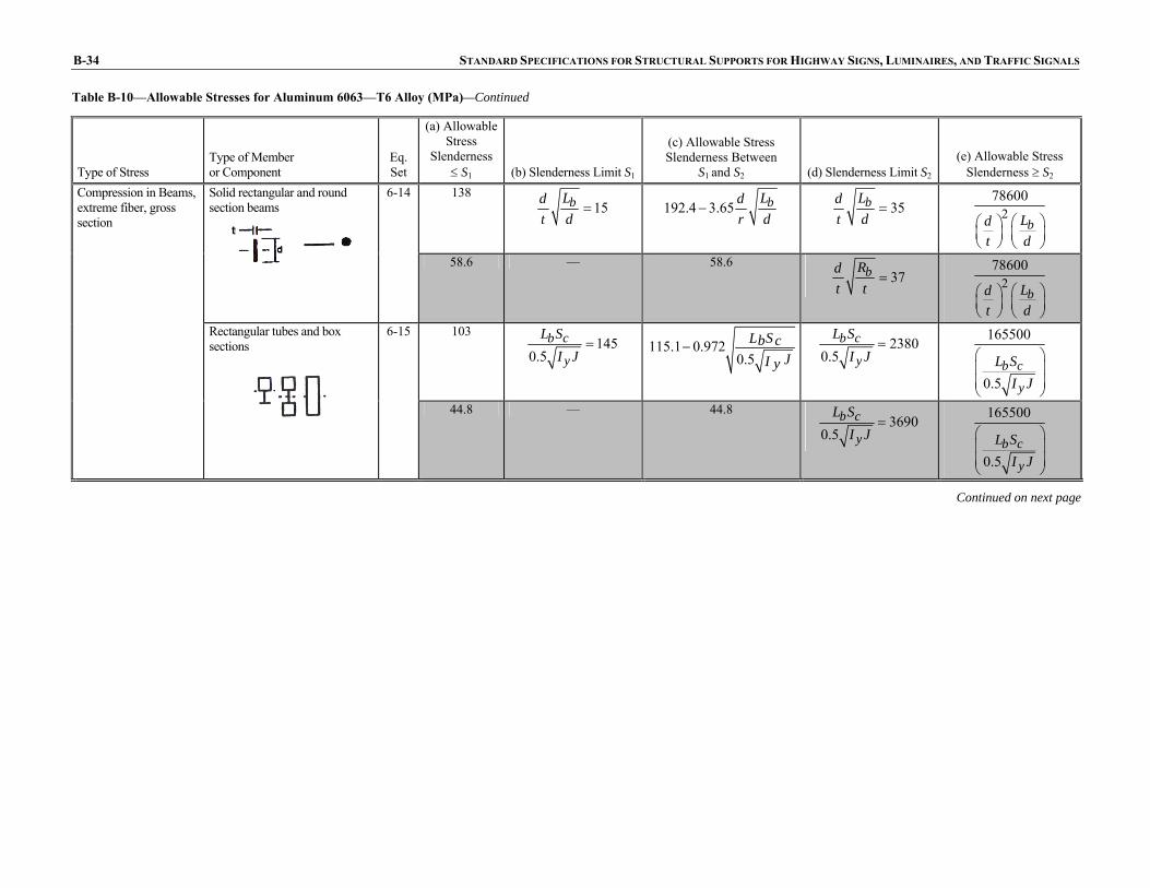
B-34 STANDARD SPECIFICATIONS FOR STRUCTURAL SUPPORTS FOR HIGHWAY SIGNS, LUMINAIRES, AND TRAFFIC SIGNALS
Table B-10—Allowable Stresses for Aluminum 6063—T6 Alloy (MPa)—Continued
Type of Stress Type of Member or Component
Eq. Set
(a) Allowable Stress
Slenderness ≤ S1 (b) Slenderness Limit S1
(c) Allowable Stress Slenderness Between
S1 and S2 (d) Slenderness Limit S2 (e) Allowable Stress
Slenderness ≥ S2 138
15bLdt d
= 192.4 3.65 bLdr d
− 35bLdt d
= 278600
bLdt d
⎛ ⎞⎛ ⎞⎜ ⎟ ⎜ ⎟⎝ ⎠ ⎝ ⎠
Solid rectangular and round section beams
6-14
58.6 — 58.6 37bRd
t t= 2
78600
bLdt d
⎛ ⎞⎛ ⎞⎜ ⎟ ⎜ ⎟⎝ ⎠ ⎝ ⎠
103 145
0.5b c
y
L SI J
= 115.1 0.9720.5
SLb cJI y
−
23800.5
b c
y
L SI J
= 165500
0.5b c
y
L SI J
⎛ ⎞⎜ ⎟⎜ ⎟⎝ ⎠
Compression in Beams, extreme fiber, gross section
Rectangular tubes and box sections
6-15
44.8 — 44.8 3690
0.5b c
y
L SI J
= 165500
0.5b c
y
L SI J
⎛ ⎞⎜ ⎟⎜ ⎟⎝ ⎠
Continued on next page
t
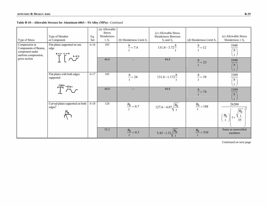
APPENDIX B: DESIGN AIDS B-35
Table B-10—Allowable Stresses for Aluminum 6063—T6 Alloy (MPa)—Continued
Type of Stress Type of Member or Component
Eq. Set
(a) Allowable Stress
Slenderness ≤ S1 (b) Slenderness Limit S1
(c) Allowable Stress Slenderness Between
S1 and S2 (d) Slenderness Limit S2 (e) Allowable Stress
Slenderness ≥ S2 103
7.4bt
= 131.0 3.72 bt
− 12bt
= 1048
bt
⎛ ⎞⎜ ⎟⎝ ⎠
Flat plates supported on one edge
6-16
44.8 — 44.8 23b
t=
1048bt
⎛ ⎞⎜ ⎟⎝ ⎠
103 24b
t= 131.0 1.172 b
t− 39b
t=
3309bt
⎛ ⎞⎜ ⎟⎝ ⎠
Flat plates with both edges supported
6-17
44.8 — 44.8 74b
t=
3309bt
⎛ ⎞⎜ ⎟⎝ ⎠
124 0.7bR
t= 127.6 4.07 bR
t− 188bR
t= 2
26200
135
bb
RR tt
⎛ ⎞⎜ ⎟⎛ ⎞ ⎜ ⎟+⎜ ⎟ ⎜ ⎟⎝ ⎠⎜ ⎟⎝ ⎠
Compression in Components of Beams, component under uniform compression, gross section
Curved plates supported on both edgesb
6-18
55.2 0.3bR
t= 5.45 1.31 bR
t− 510bR
t=
Same as nonwelded members
Continued on next page

B-36 STANDARD SPECIFICATIONS FOR STRUCTURAL SUPPORTS FOR HIGHWAY SIGNS, LUMINAIRES, AND TRAFFIC SIGNALS
Table B-10—Allowable Stresses for Aluminum 6063—T6 Alloy (MPa)—Continued
Type of Stress Type of Member or Component
Eq. Set
(a) Allowable Stress
Slenderness ≤ S1 (b) Slenderness Limit S1
(c) Allowable Stress Slenderness Between
S1 and S2 (d) Slenderness Limit S2 (e) Allowable Stress
Slenderness ≥ S2 138
9.8bt
= 192.4 5.59 bt
− 23bt
= 233780
bt
⎛ ⎞⎜ ⎟⎝ ⎠
Flat plates with compression edge free, tension edge supported
6-19
58.6 — 58.6 24b
t= 2
33780
bt
⎛ ⎞⎜ ⎟⎝ ⎠
138 51h
t= 192.4 1.07 h
t− 90h
t=
8687ht
⎛ ⎞⎜ ⎟⎝ ⎠
Compression in Components of Beams, component under bending in own plane, gross section
Flat plate with both edges supported
6-20
58.6 — 58.6 148h
t=
8687ht
⎛ ⎞⎜ ⎟⎝ ⎠
58.6 39h
t= 73.8 0.386 h
t− 78h
t= 2
268900
ht
⎛ ⎞⎜ ⎟⎝ ⎠
Shear in Webs, gross section
Unstiffened flat webs
6-21
26.9 — 26.9 100h
t= 2
268900
ht
⎛ ⎞⎜ ⎟⎝ ⎠

APPENDIX B: DESIGN AIDS B-37
Table B-11—Allowable Stresses for Aluminum 6063—T6 Alloy
Type of Stress Type of Member or Component
Eq. Set Allowable Stress
Tension, axial, net section
Any tension member
6-1 15 6.5 6063—T6 Extrusions, Pipe
Rectangular tubes, structural shapes bent around strong axis
6-2 15 6.5 White bars apply to nonwelded members and to welded members at locations farther than 1.0 in from a weld
Round or oval tubes
6-3 18 8.0 Shaded bars apply to within 1.0 in of a weld
Tension in Beams, extreme fiber, net section
Shapes bent about weak axis, bars, plates
6-4 20 8.5
On bolts 6-5 24 13.5 Bearing On flat surfaces and on bolts in slotted holes
6-6 16 9
Notes: a See Articles 6.4.1, 6.4.2.1, and 6.4.4.1 for additional provisions regarding
allowable stresses. b For tubes with circumferential welds, R/t and Rb/t, as applicable, shall be
≤20, except when the design meets the details and post-weld heat treatment requirements of Article 6.5
c See Article 6.5 for additional provisions regarding allowable stresses in welded members.
d The article numbers and equations referenced in this table refer to Section 6, “Aluminum Design.”
Continued on next page
B-38 STANDARD SPECIFICATIONS FOR STRUCTURAL SUPPORTS FOR HIGHWAY SIGNS, LUMINAIRES, AND TRAFFIC SIGNALS
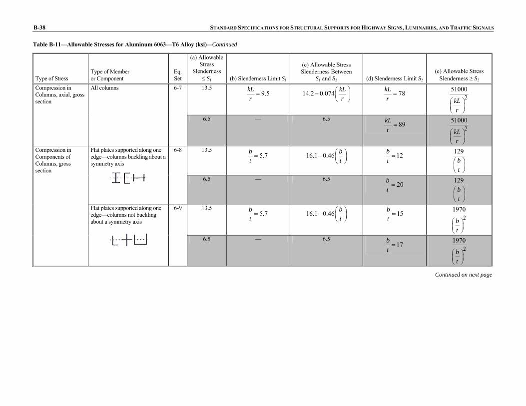
Table B-11—Allowable Stresses for Aluminum 6063—T6 Alloy (ksi)—Continued
Type of Stress Type of Member or Component
Eq. Set
(a) Allowable Stress
Slenderness ≤ S1 (b) Slenderness Limit S1
(c) Allowable Stress Slenderness Between
S1 and S2 (d) Slenderness Limit S2 (e) Allowable Stress
Slenderness ≥ S2 13.5
9.5kLr
= 14.2 0.074 kLr
⎛ ⎞− ⎜ ⎟⎝ ⎠
78kLr
= 251000
kLr
⎛ ⎞⎜ ⎟⎝ ⎠
Compression in Columns, axial, gross section
All columns
6-7
6.5 — 6.5 89kL
r= 2
51000
kLr
⎛ ⎞⎜ ⎟⎝ ⎠
13.5 5.7b
t= 16.1 0.46 b
t⎛ ⎞− ⎜ ⎟⎝ ⎠
12bt
= 129
bt
⎛ ⎞⎜ ⎟⎝ ⎠
Flat plates supported along one edge—columns buckling about a symmetry axis
6-8
6.5 — 6.5 20b
t=
129bt
⎛ ⎞⎜ ⎟⎝ ⎠
13.5 5.7b
t= 16.1 0.46 b
t⎛ ⎞− ⎜ ⎟⎝ ⎠
15bt
= 21970
bt
⎛ ⎞⎜ ⎟⎝ ⎠
Compression in Components of Columns, gross section
Flat plates supported along one edge—columns not buckling about a symmetry axis
6-9
6.5 — 6.5 17b
t= 2
1970
bt
⎛ ⎞⎜ ⎟⎝ ⎠
Continued on next page

APPENDIX B: DESIGN AIDS B-39
Table B-11—Allowable Stresses for Aluminum 6063—T6 Alloy (ksi)—Continued
Type of Stress Type of Member or Component
Eq. Set
(a) Allowable Stress
Slenderness ≤ S1 (b) Slenderness Limit S1
(c) Allowable Stress Slenderness Between
S1 and S2 (d) Slenderness Limit S2 (e) Allowable Stress
Slenderness ≥ S2 13.5
18bt
= 16.1 0.144 bt
⎛ ⎞− ⎜ ⎟⎝ ⎠
39bt
= 410bt
⎛ ⎞⎜ ⎟⎝ ⎠
Flat plates with both edges supported
6-10
6.5 — 6.5 63b
t=
410bt
⎛ ⎞⎜ ⎟⎝ ⎠
13.5 18R
t= 15.6 0.50 R
t− 188R
t= 2
3200
135
RR tt
⎛ ⎞⎜ ⎟⎛ ⎞⎜ ⎟+⎜ ⎟⎜ ⎟⎝ ⎠⎜ ⎟⎝ ⎠
Compression in Components of Columns, gross section
Curved plates supported on both edges, walls of round or oval tubesb
6-11
6.5 10R
t= 7.2 0.22 R
t− 510R
t= 2
3200
135
RR tt
⎛ ⎞⎜ ⎟⎛ ⎞⎜ ⎟+⎜ ⎟⎜ ⎟⎝ ⎠⎜ ⎟⎝ ⎠
Continued on next page

B-40 STANDARD SPECIFICATIONS FOR STRUCTURAL SUPPORTS FOR HIGHWAY SIGNS, LUMINAIRES, AND TRAFFIC SIGNALS
Table B-11—Allowable Stresses for Aluminum 6063—T6 Alloy (ksi)—Continued
Type of Stress Type of Member or Component
Eq. Set
(a) Allowable Stress
Slenderness ≤ S1 (b) Slenderness Limit S1
(c) Allowable Stress Slenderness Between
S1 and S2 (d) Slenderness Limit S2
(e) Allowable Stress Slenderness ≥ S2
15 206bR
t= 16.7 0.073 b
y
Lr
− 94by
Lr
= 2
87000
by
Lr
⎛ ⎞⎜ ⎟⎜ ⎟⎝ ⎠
Single web beams bent about strong axis
6-12
6.5 — 6.5 116b
y
Lr
= 2
87000
by
Lr
⎛ ⎞⎜ ⎟⎜ ⎟⎝ ⎠
18 33bR
t= 27.7 1.70 bR
t− 102bR
t=
Same as Eq. 6-11 with R = Rb
Round or oval tubesb
6-13
8 62bR
t= 12.8 0.61 bR
t− 206bR
t=
Same as Eq. 6-11 with R = Rb
20 15bLd
t d= 27.9 0.53 bLd
t d− 35bLd
t d= 2
11400
bLdt d
⎛ ⎞⎛ ⎞⎜ ⎟ ⎜ ⎟⎝ ⎠ ⎝ ⎠
Solid rectangular and round section beams
6-14
8.5 — 8.5 37bLd
t d= 2
11400
bLdt d
⎛ ⎞⎛ ⎞⎜ ⎟ ⎜ ⎟⎝ ⎠ ⎝ ⎠
15 145
0.5b c
y
L SI J
= 16.7 0.1410.5
b c
y
L SI J
− 23800.5
b c
y
L SI J
= 24000
0.5b c
y
L SI J
⎛ ⎞⎜ ⎟⎜ ⎟⎝ ⎠
Compression in Beams, extreme fiber, gross section
Rectangular tubes and box sections
6-15
6.5 — 6.5 3690
0.5b c
y
L SI J
= 24000
0.5b c
y
L SI J
⎛ ⎞⎜ ⎟⎜ ⎟⎝ ⎠
Continued on next page
t

APPENDIX B: DESIGN AIDS B-41
Table B-11—Allowable Stresses for Aluminum 6063—T6 Alloy (ksi)—Continued
Type of Stress Type of Member or Component
Eq. Set
(a) Allowable Stress
Slenderness ≤ S1
(b) Slenderness Limit S1
(c) Allowable Stress Slenderness Between
S1 and S2 (d) Slenderness Limit
S2 (e) Allowable Stress
Slenderness ≥ S2 15
7.4bt
= 19.0 0.54 bt
− 12bt
= 152
bt
⎛ ⎞⎜ ⎟⎝ ⎠
Flat plates supported on one edge
6-16
6.5 — 6.5 23b
t=
152bt
⎛ ⎞⎜ ⎟⎝ ⎠
15 24b
t= 19.0 0.170 b
t− 39b
t=
480bt
⎛ ⎞⎜ ⎟⎝ ⎠
Flat plates with both edges supported
6-17
6.5 — 6.5 74b
t=
480bt
⎛ ⎞⎜ ⎟⎝ ⎠
18 0.7bR
t= 18.5 0.59 bR
t− 188bR
t= 2
3800
135
bb
RR tt
⎛ ⎞⎜ ⎟⎛ ⎞⎜ ⎟+⎜ ⎟⎜ ⎟⎝ ⎠⎜ ⎟⎝ ⎠
Compression in Components of Beams, component under uniform compression, gross section
Curved plates supported on both edgesb
6-18
8 0.3bR
t= 7.9 0.19 bR
t− 510bR
t=
Same as nonwelded members
Continued on next page

B-42 STANDARD SPECIFICATIONS FOR STRUCTURAL SUPPORTS FOR HIGHWAY SIGNS, LUMINAIRES, AND TRAFFIC SIGNALS
Table B-11—Allowable Stresses for Aluminum 6063—T6 Alloy (ksi)—Continued
Type of Stress Type of Member or Component
Eq. Set
(a) Allowable Stress
Slenderness ≤ S1 (b) Slenderness Limit S1
(c) Allowable Stress Slenderness Between
S1 and S2 (d) Slenderness Limit S2
(e) Allowable Stress Slenderness ≥ S2
20 9.8b
t= 27.9 0.81b
t− 23b
t= 2
4900
bt
⎛ ⎞⎜ ⎟⎝ ⎠
Flat plates with compression edge free, tension edge supported
6-19
8.5 — 8.5 24b
t= 2
4900
bt
⎛ ⎞⎜ ⎟⎝ ⎠
20 51h
t= 27.9 0.155 h
t− 90h
t=
1260ht
⎛ ⎞⎜ ⎟⎝ ⎠
Compression in Components of Beams, component under bending in own plane, gross section
Flat plate with both edges supported
6-20
8.5 — 8.5 148h
t=
1260ht
⎛ ⎞⎜ ⎟⎝ ⎠
8.5 39h
t= 10.7 0.056 h
t− 78h
t= 2
39000
ht
⎛ ⎞⎜ ⎟⎝ ⎠
Shear in Webs, gross section
Unstiffened flat webs
6-21
3.9 — 3.9 100h
t= 2
39000
ht
⎛ ⎞⎜ ⎟⎝ ⎠
B7—REFERENCES
Author, Initials. 1985. “Graphs to Determine Structure Deflections,” Transmission and Distribution. July 1985, pp. X–Y.
Timoshenko, S. 1957. Strength of Materials—Part II. D. Van Nostrand Company, Princeton, NJ.