architecture design portfolio
DESCRIPTION
Desgin WorkTRANSCRIPT
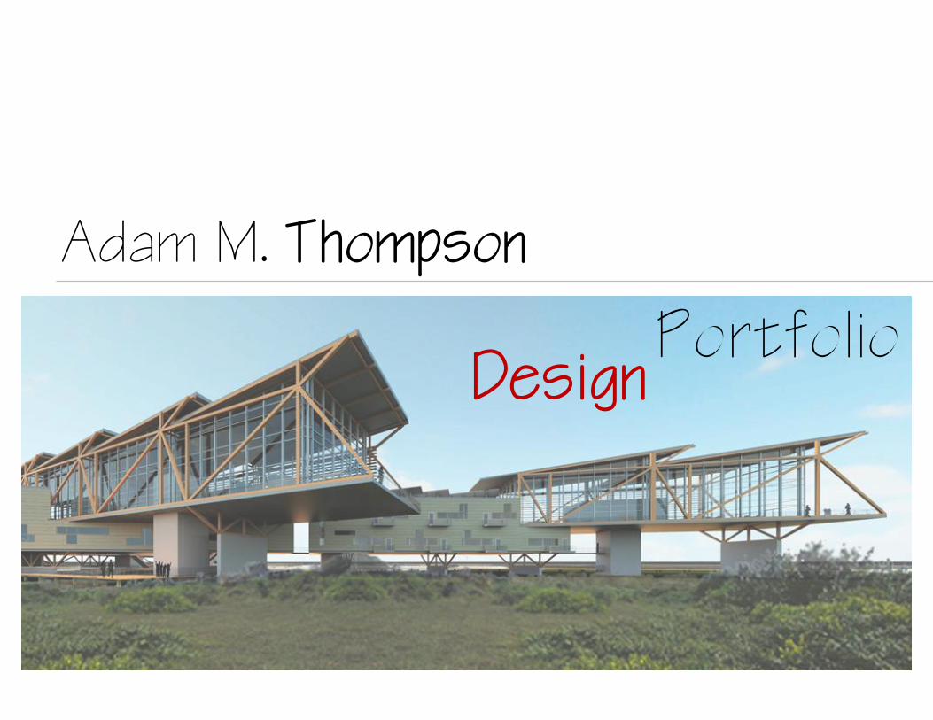
Adam M. Thompson
DesignPortfolio
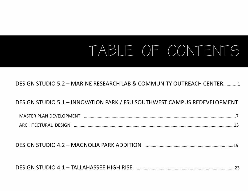
TABLE OF CONTENTS
DESIGN STUDIO 5.1 – INNOVATION PARK / FSU SOUTHWEST CAMPUS REDEVELOPMENT
MASTER PLAN DEVELOPMENT …………………………………………………………………………………………..……………………….7
ARCHITECTURAL DESIGN ………………………………………………………………………………………………………………………….13
DESIGN STUDIO 4.2 – MAGNOLIA PARK ADDITION ...…………………………………………………………….…19
DESIGN STUDIO 4.1 – TALLAHASSEE HIGH RISE …………………………………………………………………….……23
DESIGN STUDIO 5.2 – MARINE RESEARCH LAB & COMMUNITY OUTREACH CENTER……......1
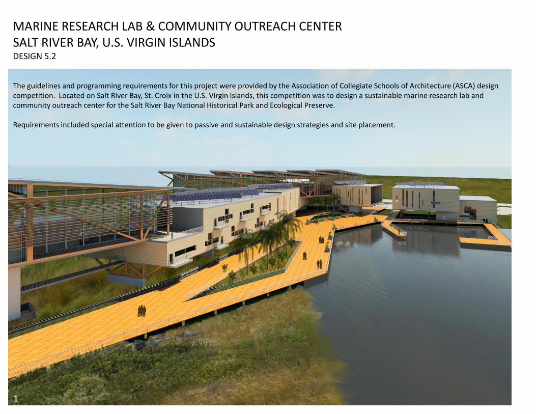
MARINE RESEARCH LAB & COMMUNITY OUTREACH CENTERSALT RIVER BAY, U.S. VIRGIN ISLANDSDESIGN 5.2
1
The guidelines and programming requirements for this project were provided by the Association of Collegiate Schools of Architecture (ASCA) design competition. Located on Salt River Bay, St. Croix in the U.S. Virgin Islands, this competition was to design a sustainable marine research lab and community outreach center for the Salt River Bay National Historical Park and Ecological Preserve.
Requirements included special attention to be given to passive and sustainable design strategies and site placement.
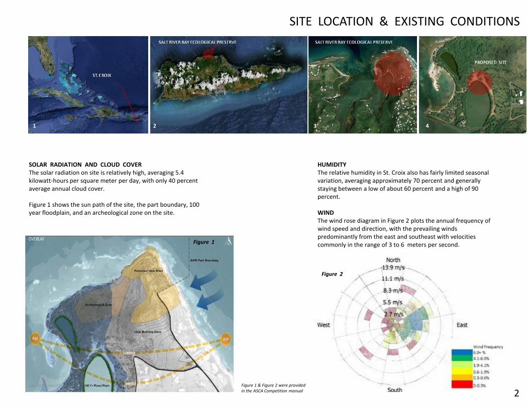
SOLAR RADIATION AND CLOUD COVERThe solar radiation on site is relatively high, averaging 5.4 kilowatt-hours per square meter per day, with only 40 percent average annual cloud cover.
Figure 1 shows the sun path of the site, the part boundary, 100 year floodplain, and an archeological zone on the site.
HUMIDITY The relative humidity in St. Croix also has fairly limited seasonal variation, averaging approximately 70 percent and generally staying between a low of about 60 percent and a high of 90 percent.
WINDThe wind rose diagram in Figure 2 plots the annual frequency of wind speed and direction, with the prevailing winds predominantly from the east and southeast with velocities commonly in the range of 3 to 6 meters per second.
SITE LOCATION & EXISTING CONDITIONS
Figure 1
Figure 2
1 2 3 4
2Figure 1 & Figure 2 were provided in the ASCA Competition manual

3
3rd Floor .2nd Floor .
1 – Restrooms2 – Mech / Elect3 – Wet labs
1 – Restrooms2 – Mech / Elect3 – Classrooms / Comp Lab4 – Storage / Collections5 – Open Office6 – Conference7 – Student Dorms (48)8 – Staff Housing (4)9 – Lab Offices
10 – Dry / Open Labs
1 – Restrooms2 – Theater3 – Touch Tanks Exhibits4 – Flexible Exhibits5 – Open Office6 – Conference7 – Student Dorms (48)8 – Recreation Area9 – Dining
10 – Kitchen
1st Floor .
SITE & FLOOR PLANS
3D-SECTION SHOWING PASSIVE DESIGN STRATEGIES SITE PLAN

4
PROGRAMMING & INTERIOR SPACES
INTERIOR PERSPECTIVE OF EXHIBIT AREAINTERIOR PERSPECTIVE BETWEEN STRUCTURE AND CURTAIN SYSTEM
The curtain system is recessed behind the main structural trusses providing a space for the public to experience the tectonics of the building and glimpse into research areas below.

5
Main Structural Truss
Secondary Compressive Load Truss
Concrete FinFloor
Roof Beams & Lateral Structure
Glazing system with Built-in structure
Louvers
EXPLODED STRUCTURAL AXONOMETRIC CORRESPONDING ELEVATION
The structural solution to accommodate the aspect of interlocking prisms was based on a series of truss systems. Two main vertical trusses and a horizontal roof system allow for a column free interior of the building. This provides a very flexible programmable interior.
The building touches the ground in an elegant manner through a system of secondary trusses and concrete fins. West Elevation
STRUCTURAL DIAGRAMS & ELEVATION
6
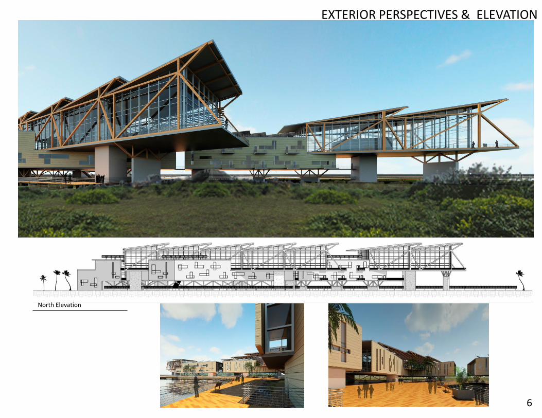
North Elevation
EXTERIOR PERSPECTIVES & ELEVATION
INNOVATION PARK / FLORIDA STATE UNIVERSITY SOUTHWEST CAMPUS MASTER PLAN REDEVELOPMENT & ARCHITECTURAL DESIGNSDESIGN 5.1
7
This project is was broken up into two sections. An initial contextual study was done of the existing Innovation Park and Florida State University Southwest Campus conditions. From that, a new master plan was developed to incorporate both institutions more cohesively. This proposed a new street and block network, buildings, parks, town and community centers, and phasing plan. The plan includes multiple building types including mixed use, R+D / education, and housing
The second part of the project focused on designing in detail one of the buildings in the new master plan. An architectural design was developed focusing on high performance and sustainable building strategies as well as studying mechanical, electrical, water, and other building systems.

The main idea of this plan was to develop a more cohesive urban fabric providing pedestrian circulation throughout the campus using connection points provided by parks and town centers, while paying special attention to sustainable design strategies.
MASTER PLAN
8
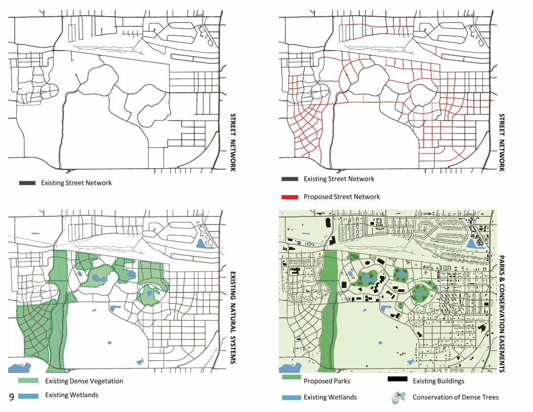
Proposed Street Network
Existing Street NetworkExisting Street Network
Existing Dense Vegetation
Existing Wetlands
Proposed Parks
Existing Wetlands
Existing Buildings
Conservation of Dense Trees
STREET
NET
WO
RK
STREET
NET
WO
RK
EXISTIN
G N
AT
UR
AL SY
STEMS
PA
RK
S & C
ON
SERV
AT
ION
EASEM
ENTS
9
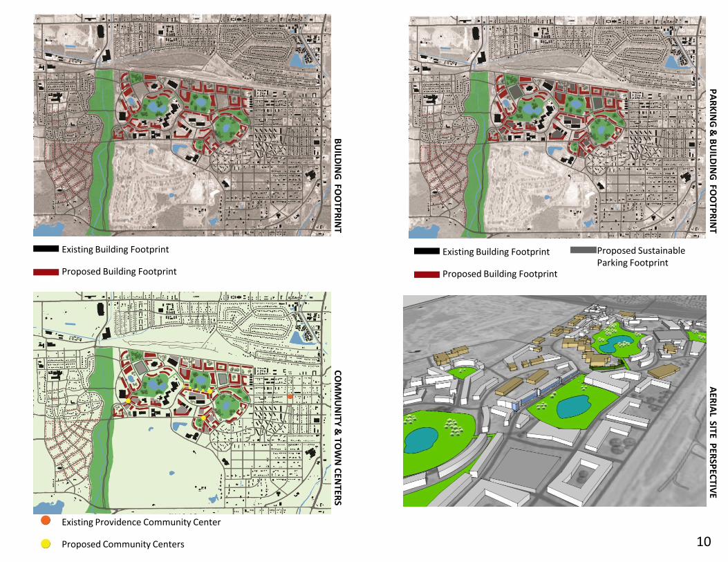
Existing Building Footprint
Proposed Building Footprint
Existing Building Footprint
Proposed Building Footprint
Proposed SustainableParking Footprint
Existing Providence Community Center
Proposed Community Centers
BU
ILDIN
G FO
OTP
RIN
T
PA
RK
ING
& B
UILD
ING
FOO
TPR
INT
CO
MM
UN
ITY &
TOW
N C
ENTER
S
AER
IAL SITE P
ERSP
ECTIV
E
10

Gateway Connections with Existing Developments
Urban Focal Points
Environmental Focal Points
Innovation Park Property Lines
FSU Southwest Campus Property Lines
Providence
Callen
North
Elberta Empire
Proposed Housing
Mabry Manor
Star Metro Bus Routes
Star Metro Bus Stops
PR
OP
ERTY
LINES
SUR
RO
UN
DIN
G N
EIGH
BO
RH
OO
DS
STAR
METR
O R
OU
TES & STO
PS
GA
TEW
AY
CO
NN
ECTIO
NS &
FOC
AL P
OIN
TS
11
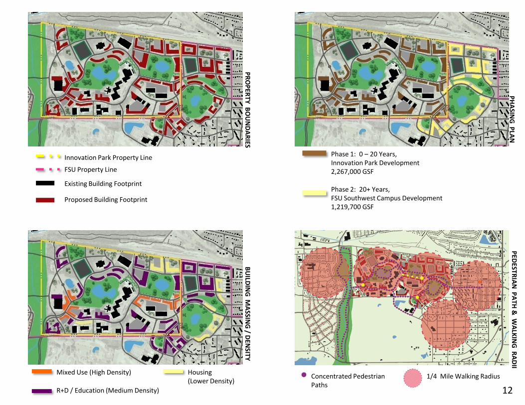
Existing Building Footprint
Proposed Building Footprint
FSU Property Line
Innovation Park Property Line
Phase 2: 20+ Years, FSU Southwest Campus Development1,219,700 GSF
Phase 1: 0 – 20 Years, Innovation Park Development 2,267,000 GSF
Mixed Use (High Density)
R+D / Education (Medium Density)
Housing (Lower Density)
PR
OP
ERTY
BO
UN
DA
RIES
PH
ASIN
G P
LAN
PED
ESTRIA
N P
ATH
& W
ALK
ING
RA
DII
BU
ILDIN
G M
ASSIN
G / D
ENSITY
Concentrated Pedestrian Paths
1/4 Mile Walking Radius
12

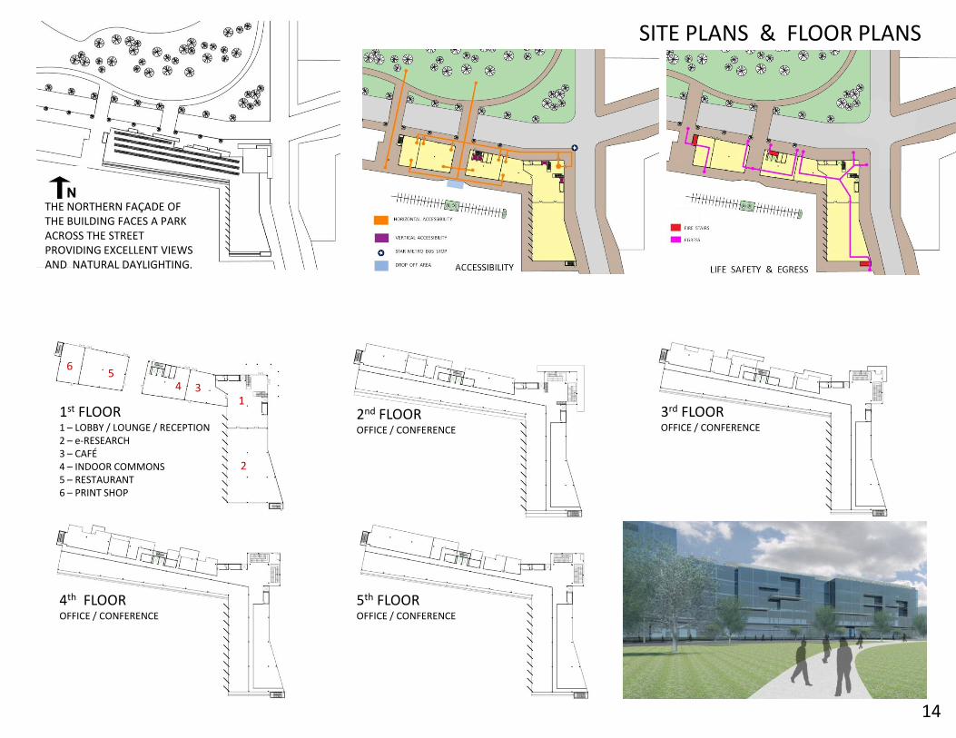
The following is the architectural design for a five story, 202,500GSF mixed use building to be located on the new Innovation Park campus. This building design incorporates a café, print shop, retail space, indoor commons, and e-research rooms on the ground floor, with classrooms, offices, and conference centers on the top four floors.
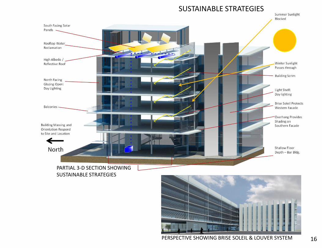
Sustainable / Green systems are incorporated throughout the building design that include building orientation, water reclamation and treatment, and passive solar strategies.
INNOVATION PARK ARCHITECTURAL DESIGN:
13
1
2
35
4
6
2nd FLOOROFFICE / CONFERENCE
3rd FLOOROFFICE / CONFERENCE
4th FLOOROFFICE / CONFERENCE
5th FLOOROFFICE / CONFERENCE
1st FLOOR1 – LOBBY / LOUNGE / RECEPTION2 – e-RESEARCH3 – CAFÉ 4 – INDOOR COMMONS5 – RESTAURANT 6 – PRINT SHOP
THE NORTHERN FAÇADE OF THE BUILDING FACES A PARK ACROSS THE STREET PROVIDING EXCELLENT VIEWS AND NATURAL DAYLIGHTING.
14
SITE PLANS & FLOOR PLANS

15
BUILDING SYSTEMSELECTRICAL
LATERAL & COMPRESSIVESTRUCTURAL FIGURE GROUND
ELECTRICAL SUPPLY
PHOTOVOLTAIC INPUT 0
SUPPLY AIR
RETURN AIR
RESTROOMS
POTABLE WATER
GREY WATER STORAGE& COLLECTION
WATER
MECHANICAL
16
SUSTAINABLE STRATEGIES
PERSPECTIVE SHOWING BRISE SOLEIL & LOUVER SYSTEM
PARTIAL 3-D SECTION SHOWING SUSTAINABLE STRATEGIES
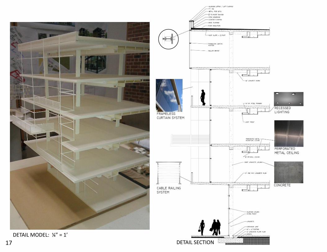
DETAIL SECTION
DETAIL MODEL: ¼” = 1’
17
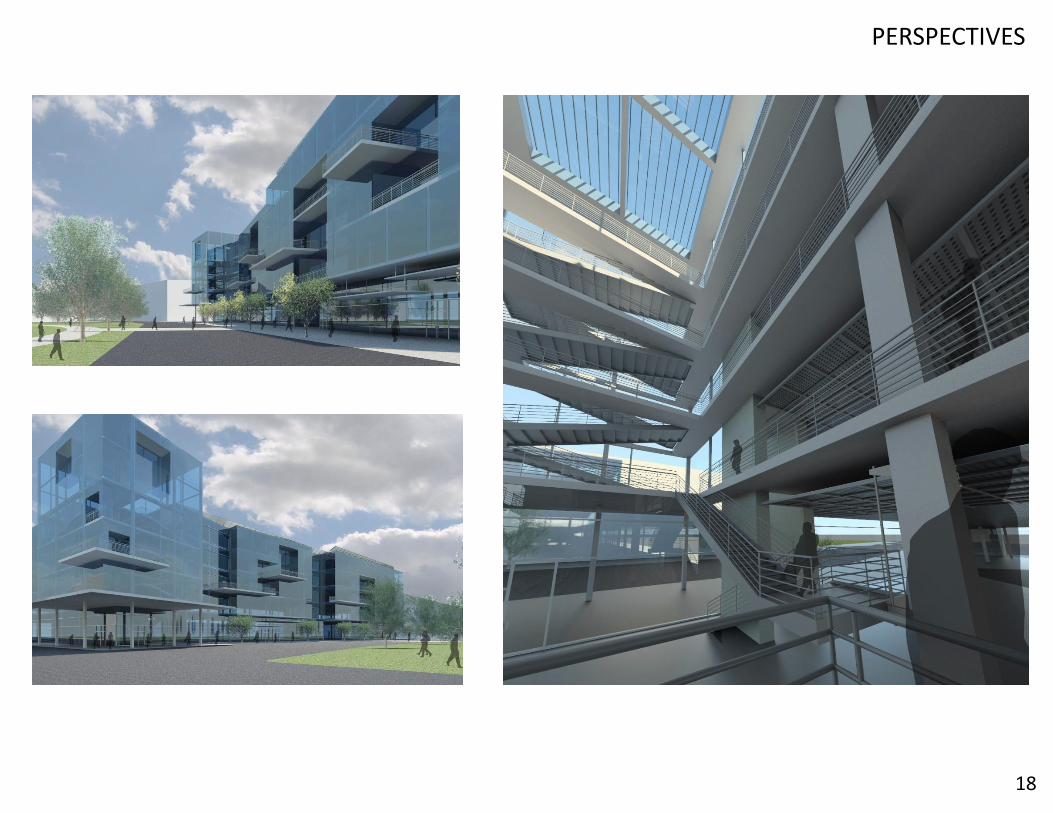
18
PERSPECTIVES
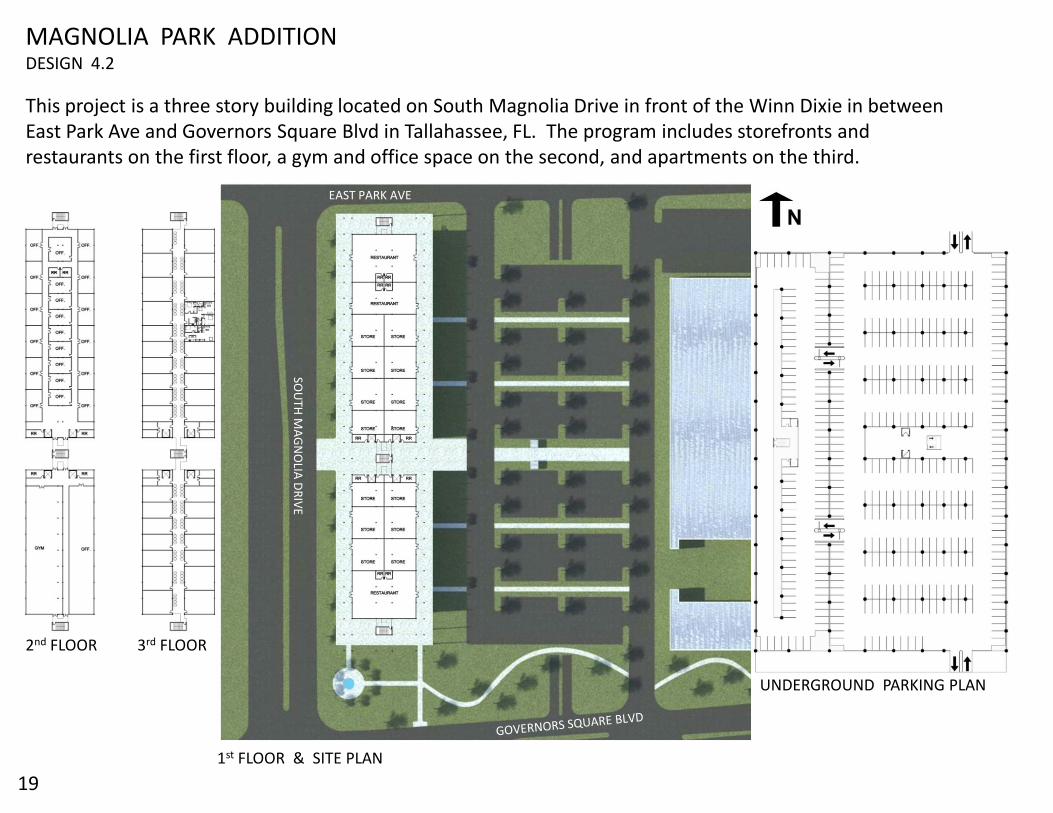
2nd FLOOR 3rd FLOOR
1st FLOOR & SITE PLAN
UNDERGROUND PARKING PLAN
This project is a three story building located on South Magnolia Drive in front of the Winn Dixie in between East Park Ave and Governors Square Blvd in Tallahassee, FL. The program includes storefronts and restaurants on the first floor, a gym and office space on the second, and apartments on the third.
SOU
TH M
AG
NO
LIA D
RIV
E
EAST PARK AVE
19
MAGNOLIA PARK ADDITIONDESIGN 4.2

RENDERED WEST ELEVATION
PERSPECTIVEPERSPECTIVE
PERSPECTIVE AERIAL SITE PERSPECTIVE
20
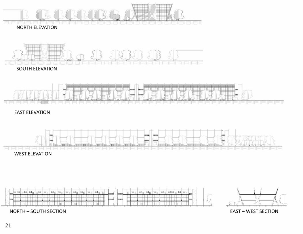
WEST ELEVATION
EAST ELEVATION
NORTH ELEVATION
SOUTH ELEVATION
NORTH – SOUTH SECTION EAST – WEST SECTION
21

DETAIL SECTIONPERSPECTIVE
PERSPECTIVE
22
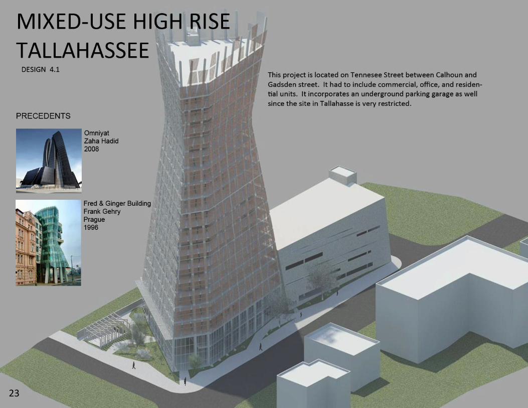
23
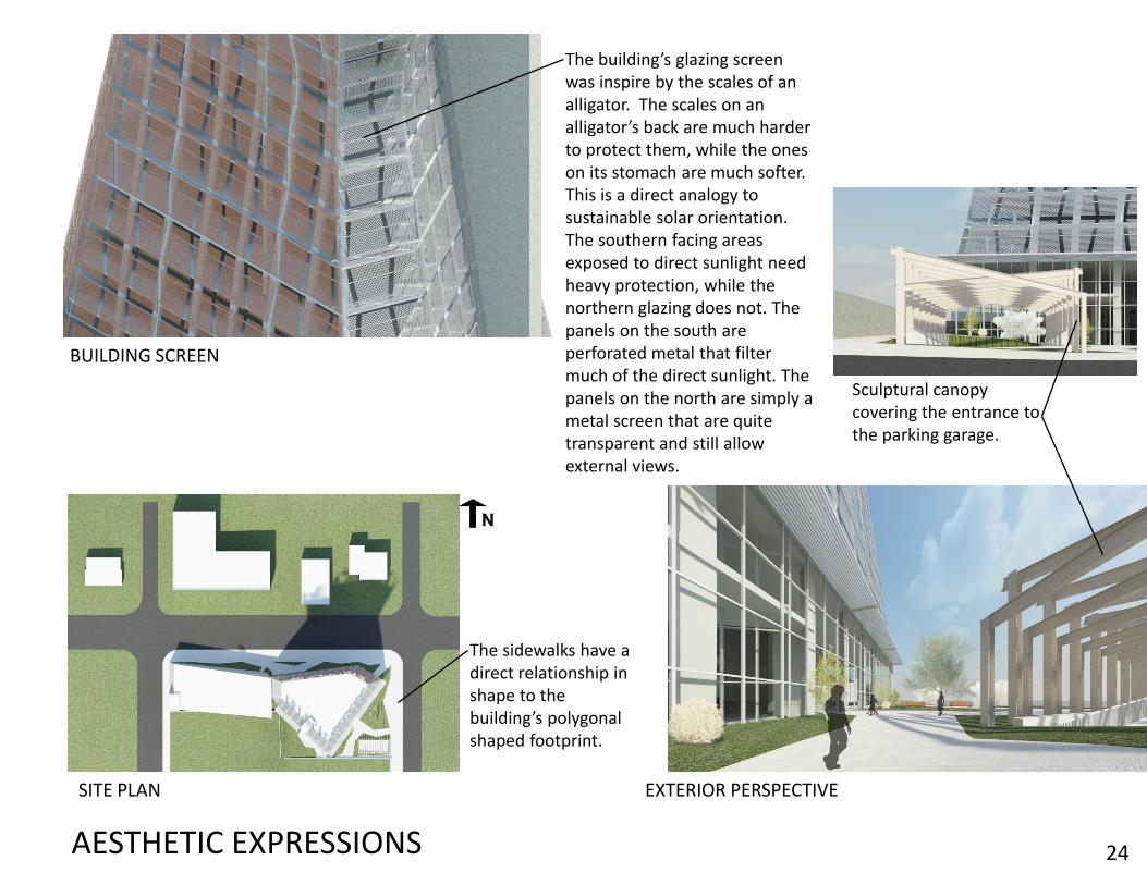
The building’s glazing screen was inspire by the scales of an alligator. The scales on an alligator’s back are much harder to protect them, while the ones on its stomach are much softer. This is a direct analogy to sustainable solar orientation. The southern facing areas exposed to direct sunlight need heavy protection, while the northern glazing does not. The panels on the south are perforated metal that filter much of the direct sunlight. The panels on the north are simply a metal screen that are quite transparent and still allow external views.
AESTHETIC EXPRESSIONS
The sidewalks have a direct relationship in shape to the building’s polygonal shaped footprint.
Sculptural canopycovering the entrance tothe parking garage.
SITE PLAN
BUILDING SCREEN
EXTERIOR PERSPECTIVE
24

A
25
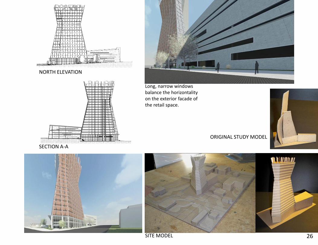
NORTH ELEVATION
SECTION A-A
Long, narrow windowsbalance the horizontalityon the exterior facade ofthe retail space.
ORIGINAL STUDY MODEL
SITE MODEL 26