arduino 02 02
TRANSCRIPT
8/9/2019 Arduino 02 02
http://slidepdf.com/reader/full/arduino-02-02 1/4
2. Digital
- Button
Button
Pushbuttons or switches connect two points in a circuit when you press
them. This example turns on the built-in LED on pin 13 when you press the
button.
Hardware
- Arduino Board
- A momentary button or switch
- 10K ohm resistor
- Breadboard
- Hook-up wire
Circuit
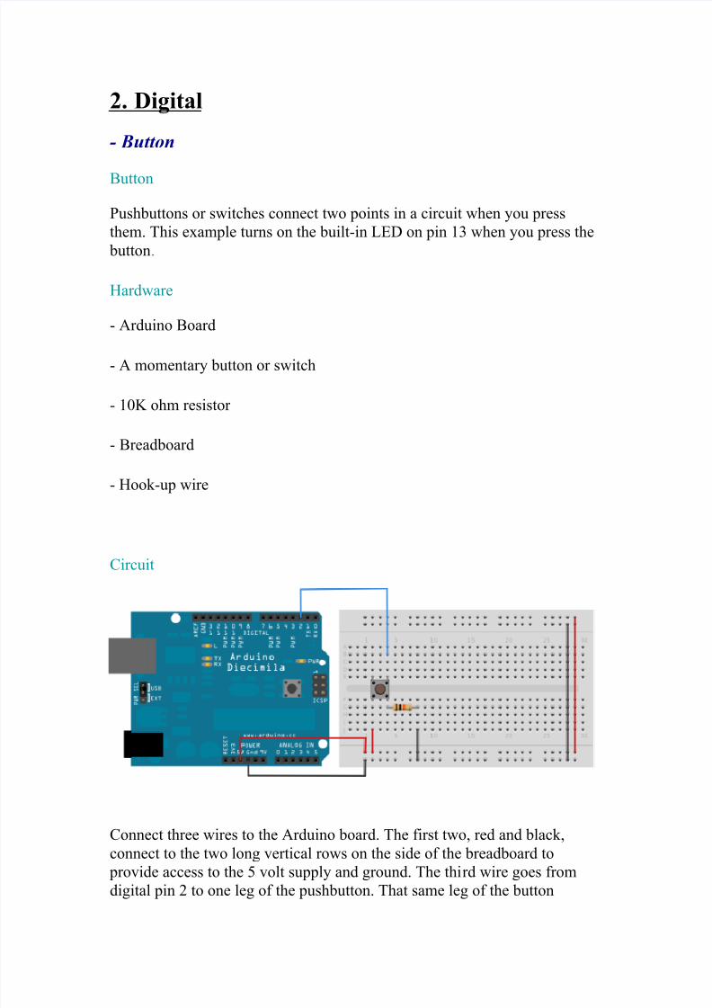
Connect three wires to the Arduino board. The first two, red and black,
connect to the two long vertical rows on the side of the breadboard to
provide access to the 5 volt supply and ground. The third wire goes from
digital pin 2 to one leg of the pushbutton. That same leg of the button

8/9/2019 Arduino 02 02
http://slidepdf.com/reader/full/arduino-02-02 2/4
connects through a pull-down resistor (here 10 KOhms) to ground. The
other leg of the button connects to the 5 volt supply.
When the pushbutton is open (unpressed) there is no connection between the
two legs of the pushbutton, so the pin is connected to ground (through the pull-down resistor) and we read a LOW. When the button is closed
(pressed), it makes a connection between its two legs, connecting the pin to
5 volts, so that we read a HIGH.
You can also wire this circuit the opposite way, with a pullup resistor
keeping the input HIGH, and going LOW when the button is pressed. If so,
the behavior of the sketch will be reversed, with the LED normally on and
turning off when you press the button.
If you disconnect the digital i/o pin from everything, the LED may blinkerratically. This is because the input is "floating" - that is, it will randomly
return either HIGH or LOW. That's why you need a pull-up or pull-down
resistor in the circuit.
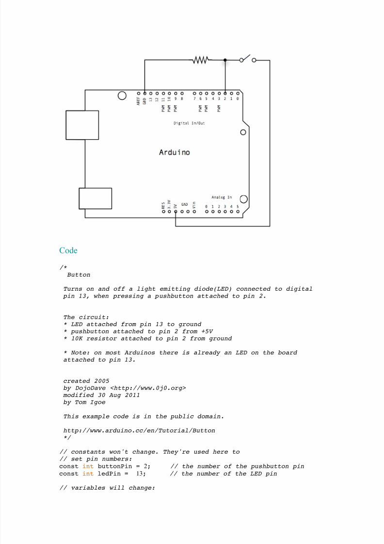
Schematic:
8/9/2019 Arduino 02 02
http://slidepdf.com/reader/full/arduino-02-02 3/4
Code
/*
Button
Turns on and off a light emitting diode(LED) connected to digital
pin 13, when pressing a pushbutton attached to pin 2.
The circuit:* LED attached from pin 13 to ground
* pushbutton attached to pin 2 from +5V
* 10K resistor attached to pin 2 from ground
* Note: on most Arduinos there is already an LED on the board
attached to pin 13.
created 2005by DojoDave <http://www.0j0.org>
modified 30 Aug 2011by Tom Igoe
This example code is in the public domain.
http://www.arduino.cc/en/Tutorial/Button
*/
// constants won't change. They're used here to
// set pin numbers:
const int buttonPin = 2; // the number of the pushbutton pin
const int ledPin = 13; // the number of the LED pin
// variables will change:

8/9/2019 Arduino 02 02
http://slidepdf.com/reader/full/arduino-02-02 4/4
int buttonState = 0; // variable for reading the pushbutton
status
void setup() {
// initialize the LED pin as an output: pinMode(ledPin, OUTPUT);
// initialize the pushbutton pin as an input: pinMode(buttonPin, INPUT);
}
void loop(){
// read the state of the pushbutton value:
buttonState = digitalRead(buttonPin);
// check if the pushbutton is pressed.
// if it is, the buttonState is HIGH: if (buttonState == HIGH) {
// turn LED on:
digitalWrite(ledPin, HIGH);
}
else {// turn LED off: digitalWrite(ledPin, LOW);
}
}