as a part of green initiative by bis only soft copy of ...7975)_04022016.pdf · is 1893:1962...
TRANSCRIPT

As a part of Green Initiative by BIS only Soft Copy of this communication is being sent
MANAK BHAVAN, 9 BAHADUR SHAH ZAFAR MARG, NEW DELHI 110002
Phone: + 91 11 23230131, 23233375, 23239402 Extn 4434; Fax: + 91 11 23235529
व्यापक पपक चाला मौद ा हौाााद ंर्भ : दीईडी39/टी-10 03 फावाी2016 तपमीप दिौित : र्ूपंपक ीयइंजीिमयचागंववषयदिौित,दीईडी39पेदर्ीद स्य
.............................................................................................................................................................................. प्राप्तपताभ:
1 िदवव इंजीिमयाीववर्ागपक चाषद्पेरूचलाखमेवा ेद स्य 2 दीईडी39 पेदर्ीद स्य 3 रूचलाखमेवा ेअन्यिमपाय
ौहो य(यों), निम्िलिखित ानि नाौदानौलख्िैं:
प्र ेखदखं्या शीषभप
दीईडी39(7975)WC दांलमाओं पे र्ूपम्पक ाोधी डडजाइम पे ौाम ंड र्ाग 1 दाौान्य प्रावधाम औा र्वम पे द शािम ेश (IS 1893 (र्ाग1) प छठी पक ुमाीक्षण) पा व्यापक पपक चाला मौद ा
ृपयनइौानि ेाौदाे नअवखो ि रेंऔरअपिीौम्ान य यैत न े एै ेे ेें क यदायेानि ेरूपाेंप्र नलिि ैो ोइिपरअाख रिे ाें आप ेव्यवौनयअववन नरोतनराेंक्यन दािनइयन आौ ीैं
ौम्ान यन ेेेिे ीअलन ान थव:15 अप्र ै2016 ौम्ान ोई ैो ो ृपयन अधोैस् नक्षरीरक ोरपरलिखित प ेपरौलख्िफोौेटाेंेे ेें यन
[email protected] परईाेख राें यदा ोईौम्ान प्रन् िैकलैो ी ैअववनौम्ान ाें ेवखेनानौम्तन्धीरुटएदह एैई ोरपरोक् प्रखेत ोयवनव अलन ारूपदायनेन गन यदाौम्ान िी ीप्र ृन ी एैई ोिवायौलिान ेअध्यक्षरी ेपरनािश ौेअववनरि ीइ् नपरआगे ी नयश वनैक ेलिख िवायौलिान ोेेेेेनिे ेतनाप्रखेत ोअलन ारूपाेदायनेन गन यैप्रखेतेनर ीयानि ब्यरूो ीव तौनइहwww.bis.org.inपरेी ै धन्यवना
ेवाकय,
(बीपेिदन्हा ) द ंग्म:उपक चा खितखतप्रौखु (िदवव इंजीिमयाी)

MANAK BHAVAN, 9 BAHADUR SHAH ZAFAR MARG, NEW DELHI 110002
Phone: + 91 11 23230131, 23233375, 23239402 Extn 4434; Fax: + 91 11 23235529
DRAFT IN WIDE CIRCULATION
Our Ref: CED 39/T- 10 03 February 2016
Technical Committee: Earthquake Engineering Sectional Committee, CED 39
Addressed to:
1 All Members of the Civil Engineering Division Council, CEDC 2 All Members of the Earthquake Engineering Sectional Committee, CED 39 and
its sub-committees and Panels, CED 39:4, CED 39:10, CED 39:4/P-1 and CED 39/P1 3 All others interested
Dear Sir/Madam,
Please find enclosed the following draft:
Document No. Title
Doc: CED 39(7975) Draft Indian Standard Guidelines for Criteria For Earthquake Resistant Design Of Structures: Part 1 – General Provisions For All Structures And Specific Provisions For Buildings [Sixth Revision of IS 1893 (Part 1)]
Kindly examine the draft and forward your views stating any difficulties which you are likely to experience in your business or profession, if this is finally adopted as National Standard.
Last Date for comments: 15 April 2016
Comments if any, may please be made in the format as attached and mailed to the undersigned at the above address. You are requested to send your comments preferably through e-mail to [email protected].
In case no comments are received or comments received are of editorial nature, you will kindly permit us to presume your approval for the above document as finalized. However, in case of comments of technical in nature are received then it may be finalized either in consultation with the Chairman, Sectional Committee or referred to the Sectional Committee for further necessary action if so desired by the Chairman, Sectional Committee.
The document is also hosted on BIS website, www.bis.org.in.
Thanking you, Yours faithfully,
(B.K. Sinha) Head (Civil Engg.) Encl: As above

FORMAT FOR SENDING COMMENTS ON THE DOCUMENT [Please use A4 size sheet of paper only and type within fields indicated. Comments on each clause/sub-clause/ table/figure, etc, be stated on a fresh row. Information/comments should include reasons for comments, technical references and suggestions for modified wordings of the clause. Comments through e-mail in MS WORD format to [email protected] shall be appreciated.]
Doc. No.:CED 39(7975)WC BIS Letter Ref: CED 39/T-10 Dated: 03 Feb 2016
Title: Criteria For Earthquake Resistant Design Of Structures: Part 1 – General Provisions For All Structures And Specific Provisions For Buildings [ Sixth Revision of IS 1893 (Part 1)] Name of the Commentator or Organization: ____________________________________
Clause No. with
Para No. or Table No. or Figure No.
commented (as applicable)
Abbreviation of the
commentator
Comments/Modified Wordings
Justification for the Proposed Change
Draft for Comments only CED 39(7975)WC February 2016
1
Draft Indian Standard (Not to be reproduced without the permission of BIS or used as an Indian Standard)
CRITERIA FOR EARTHQUAKE RESISTANT DESIGN OF STRUCTURES:
PART 1 – GENERAL PROVISIONS FOR ALL STRUCTURES AND SPECIFIC PROVISIONS FOR BUILDINGS
[ Sixth Revision of IS 1893 (Part 1)]
ICS 91.120.25
Earthquake Engineering Last Date for Comments Sectional Committee, CED 39 15 April 2016
Foreword Formal clause will be added later.
Himalayan-Nagalushai region, Indo-Gangetic Plain, Western India, Kutch and Kathiawar regions are geologically unstable parts of the country, where devastating earthquakes have occurred. Also, a major part of the Peninsular India has been visited by strong earthquakes, but these were relatively few in number occurring at long intervals of time. Earthquake resistant design is essential, considering effects from studies of these Indian earthquakes and experiences collected worldwide, particularly in view of the extensive development of built environment underway in the country. IS 1893:1962 'Recommendations for earthquake resistant design of structures' was published in 1962 and revised first time in 1966. As a result of additional experiences collected in India and further knowledge and experience gained since the publication of the First Revision of this standard, the Sectional Committee felt the need to revise the standard again incorporating many changes, such as revision of maps showing seismic zones and epicenters, and adding a more rational approach for design of buildings and sub-structures of bridges. These were covered in the Second Revision of IS 1893 brought out in 1970. As a result of the increased use of the standard, considerable amount of suggestions were received for modifying some of the provisions of the standard, and, therefore, Third Revision of the standard was brought out in 1975. It incorporated the following changes:
(1) The standard incorporated seismic zone factors (previously given as multiplying factors in the second revision) on a more rational basis.
(2) Importance factors were introduced to account for the varying degrees of importance for various structures.
(3) In the clauses for design of multi-storeyed buildings, the flexibility of the structure was incorporated in the form of a curve for the coefficient of flexibility with respect to natural period of buildings.
(4) A more rational method was suggested to combine modal shear forces. (5) New clauses were introduced for determination of hydrodynamic
Draft for Comments only CED 39(7975)WC February 2016
2
pressures in elevated tanks. (6) Clauses on concrete and masonry dams were modified, taking into
account their dynamic behaviour during earthquakes. Simplified expressions were introduced for estimating design forces, based on results of studies carried out since publication of the second revision of the standard.
The Fourth Revision, brought out in 1984, modified some provisions of the standard as a result of experience gained with the use of the standard. In this revision, important basic modifications were introduced with-respect to load factors, field values of N, base shear and modal analysis. A new concept was incorporated of performance factor, which depended on structural framing system employed in design and ductility incorporated in construction. Fig. 3 for design acceleration spectra was modified; a curve was introduced for zero percent damping. In the Fifth Revision brought out in 2002, the Sectional Committee decided to present the provisions for different types of structures in separate parts, to keep abreast with rapid developments and extensive research carried out in earthquake-resistant design of various structures. Hence, IS 1893 was split into five parts, namely:
(a) Part 1: General provisions and buildings (b) Part 2: Liquid retaining tanks – Elevated and Ground Supported (c) Part 3: Bridges and Retaining Walls (d) Part 4: Industrial Structures, including Stack-Like Structures (e) Part 5: Dams and embankments
Part 1 contained general provisions on earthquake hazard assessment applicable to all structures covered in the above five parts. Also, it contained provisions specific to earthquake-resistant design of buildings. Unless stated otherwise, the provisions in Parts 2 to 5 were to be read necessarily in conjunction with the general provisions laid down in Part 1. The major modifications made in the Fifth Revision included:
(1) Seismic zone map was revised with only four zones, instead of five. Erstwhile Zone I was merged to Zone II. Hence, Zone I did not appear in the new zoning, and only Zones II, III, IV and V did.
(2) Values of seismic zone factors were changed; they reflected more realistic values of effective peak ground acceleration of the Maximum Considered Earthquake (MCE).
(3) Response Design Acceleration spectra were specified for three types of founding strata, namely (a) rocky or hard soil, (b) medium or stiff soil, and (c) soft soil.
(4) Empirical expression were revised for estimating the fundamental natural period Ta of multi-storeyed buildings with regular moment resisting frames.
(5) A revised approach was adopted in seismic design. First, the actual earthquake force was to be estimated, which may be induced in the structure during the MCE, if it were to remain elastic. Then, the design earthquake force was to be estimated, by dividing this induced elastic force by a Response Reduction Factor R; R explicitly accounted for ductile deformation, overstrength, redundancy, and replaced the earlier
Draft for Comments only CED 39(7975)WC February 2016
3
performance factor. (6) A lower bound was specified for the design base shear of buildings, based
on empirical estimate of the fundamental natural period, Ta. (7) Soil-foundation system factor was dropped. Instead, a clause was
introduced to restrict the use of foundations vulnerable to differential settlements in severe seismic zones.
(8) Torsional eccentricity values were revised upwards in view of serious damages observed in buildings with irregular plan configurations.
(9) Modal combination rule was revised in dynamic analysis of buildings. (10) Other clauses were redrafted, where necessary, for more effective
implementation. In this current (Sixth) revision, in addition to others, the following significant changes have been included:
1) Additional clarity on how to handle different types of irregularity of structural system;
2) Explicitly including effect of masonry infill walls on design of frame buildings;
3) Simplifying torsional provisions; and 4) Including simplified method for liquefaction potential analysis.
Structures designed as per this standard are expected to sustain structural damage, but are not expected to collapse during strong earthquake ground shaking. In seismically active areas, construction should be avoided of structures, which may result in heavy debris and consequent loss of life and property, such as un-reinforced masonry (for example, adobe, stone or brick masonry in mud mortar, and random rubble stone masonry). Earthquake can cause damage not only on account of the shaking which results from them, but also due to other chain effects, like landslides, floods, tsunamis, fires and disruption to communication. Therefore, it is important to take necessary precautions in the siting, planning and design of structures, so that they are safe against such secondary effects also. The provisions of this standard are intended for earthquake resistant design of only normal structures. This standard is not applicable for the earthquake hazard estimate and earthquake resistant design of special structures (such as large and tall dams, long-span bridges and major industrial projects). Such projects require rigorous, site-specific investigation to arrive at the earthquake hazard assessment. Also, the higher earthquake performance expectation from the special structures may require designers to depart from the general principles of earthquake-resistant design enunciated for normal structures in Parts 1 to 5 of this standard. The Sectional Committee recognizes the urgent need for a quantitative basis for earthquake zoning and earthquake hazard assessment. But, arriving at a quantitative earthquake zoning for India is not possible currently, owing to a number of factors, including the scant availability of instrument recorded data. Thus, the current earthquake zone map of India is based on maximum earthquake intensity sustained by each location during the past earthquakes in India.

Draft for Comments only CED 39(7975)WC February 2016
4
Though the magnitudes of different earthquakes which have occurred in the past are estimated reasonably well, the maximum intensities of ground shaking at different places caused by these earthquakes have so far been estimated mostly by post-earthquake field damage surveys; there is little instrumental evidence to corroborate the conclusions so arrived at. Thus, a zoning map, which is based on the maximum intensities arrived at each location in the nation, is likely to lead to incorrect conclusions in view of (a) possible human errors in judgment during the damage survey for assessment of intensities, and (b) variation in quality of design and construction of structures causing variation in type and extent of damage to the structures for the same intensity of shaking. Therefore, the Sectional Committee has considered that an interim rational approach to arrive at an earthquake zoning map would be one based on the maximum intensities at each location as recorded from damage surveys after past earthquakes, modified to account for:
(a) known magnitudes and the known epicentres (see Annex A) assuming all other conditions as being average, and
(b) tectonics (see Annex B) and lithology (see Annex C) of each region. Also, the Committee reviewed the map so arrived at with the past history, and drew lines demarcating the different zones so as to be clear of important towns, cities and industrial areas, to address economics of projects in such areas. Maps shown in Figure 1 and Annexes B & C were prepared based on the information available upto 1993. However, Annex A is prepared based on information available from January 1505 to December 2013. The Sectional Committee has attempted to include a Seismic Zoning Map (Fig. 1) for this purpose. The object of this map is to classify the area of the country into a number of zones in which one may reasonably expect earthquake shaking of more or less same maximum intensity in future. The intensity as per 1964 MSK Intensity Scale (see Annex D) broadly associated with the various zones is VI (or less), VII, VIII and IX (and above) for Zones II, III, IV and V respectively. The maximum seismic ground acceleration in each zone has not been predicted with accuracy either on a deterministic or on a probabilistic basis. The Seismic Zone Factors included herein are considered values of normalized effective peak ground accelerations to be adopted in the design of various structures covered in this standard. Seismic Zone Factors for some important towns are given in Annex E. In the 2002 Seismic Zone Map, Zones I and II of the 1970 Seismic Zone Map were merged and assigned the level of Seismic Zone II. Considering the seismicity in southern India,
(a) the region that was affected by the 1993 Killari earthquake was included in Zone III;
(b) the Bellary isolated zone was removed; and (c) in parts of east coast areas showing hazard similar to that of the Killari
area, the level of Zone II was enhanced to Zone III and connected with Zone III of Godavari Graben area.
The seismic hazard level goes on progressively increasing from southern peninsular
Draft for Comments only CED 39(7975)WC February 2016
5
portion to the Himalayan main seismic source. The revised seismic zoning map gave status of Zone III to Narmada Tectonic Domain, Mahanadi Graben and Godavari Graben. This is a logical normalization keeping in view the apprehended higher strain rates in these domains on geological consideration of higher neo-tectonic activity recorded in these areas. Attention is particularly drawn to the fact that the intensity of ground shaking due to an earthquake could vary locally at any place due to variation in soil conditions. Earthquake response of systems would be affected by different types of foundation system in addition to variation of ground motion due to various types of soils. Considering the effects in a gross manner, the standard gives guidelines for arriving at design seismic coefficients based on stiffness of base soil reflected by the corrected SPT values. The design horizontal acceleration coefficient specified in this standard for the design of a structure, is dependent on many factors. It is an extremely difficult task to determine the exact design horizontal acceleration coefficient in each given case. Therefore, it is necessary to indicate broadly the design horizontal acceleration coefficients that could be adopted generally in different parts or zones of the country, though, of course in the case of all important projects, rigorous analyses shall be performed considering all factors involved, to arrive at suitable design horizontal acceleration coefficients. The effects of the maximum credible earthquake in the four seismic zones may be taken to be twice that of the effects of the design seismic coefficient specified in this standard for the respective seismic zones. Though the basis for the design of different types of structures is covered in this standard, it is not implied that detailed dynamic analysis should be made in every case. Base isolation and energy absorbing devices may be used for earthquake resistant design. Only standard devices having detailed experimental data on the performance should be used. The designer must demonstrate by detailed analyses that these devices provide sufficient protection to the buildings and equipment as envisaged in this standard. Performance of all assembled isolation and energy absorbing devices should be evaluated experimentally, and duly approved by the competent authority identified by the client owner of the structure, before such devices are used in practice. Design of buildings and equipment using such device should be reviewed by a competent authority. In general, base isolation systems are found useful for short period structures, say those with fundamental periods, including soil-structure interaction less than 0.7s. To control the serious loss of life and economic loss, the technique of base isolation can be an alternate damage control strategy, which should be promoted or encouraged in Seismic Zones III, IV and V. The commonly used seismic isolators are:
(i) laminated natural rubber bearings,
(ii) high damping rubber bearings,
(iii) laminated lead rubber bearings, and
(iv) sliding bearings.
Draft for Comments only CED 39(7975)WC February 2016
6
A combination of different types of isolators can be adopted to achieve satisfactory stiffness of the isolation system. Supplementary dampers (viscous or metallic-yielding dampers) can be used along with base isolation systems, to reduce relative displacement demand on the isolated superstructure. Currently, the Indian Standard for design of base isolated buildings is under preparation; until such a standard is available, specialist literature should be consulted for design, detail, installation and maintenance of base isolation systems. In the preparation of this standard, effort has been made to coordinate with standards and practices prevailing in different countries in addition to relating it to the practices in the field in this country. Assistance has particularly been derived from the following publications:
(a) IBC 2015, International Building Code, International Code Council, USA, 2015;
(b) NEHRP 2009, NEHRP Recommended Provisions for Seismic Regulations for
New Buildings and Other Structures, Report No. FEMA P-750, Federal Emergency Management Agency, Washington, DC, USA, 2009;
(c) ASCE/SEI 7-10, Minimum Design Loads for Buildings and Other Structures,
American Society of Civil Engineers, USA, 2010; and
(d) NZS 1170.5: 2004, Structural Design Actions, Part 5: Earthquake Actions – New
Zealand, Standards New Zealand, Wellington, New Zealand, 2004.
Also, considerable assistance has been given by Indian Institutes of Technology Bombay, Kanpur, Madras, Roorkee and Jodhpur; Geological Survey of India; India Meteorological Department, National Centre for Seismology (Ministry of Earth Sciences, Govt. of India) and several other organizations. Significant improvements have been made to the standard through a project entitled, "Review of Building Codes and Preparation of Commentary and Handbooks" awarded to IIT Kanpur by the Gujarat State Disaster Management Authority (GSDMA), Gandhinagar, through World Bank finances during 2003-2004. For the guidance of users, informative annexes have been included on ‘performance based design’ and ‘design of slab-column systems’ at Annex G and Annex H respectively. The units used with the items covered by the symbols shall be consistent throughout this standard, unless specifically noted otherwise. For the purpose of deciding whether a particular requirement of this standard is complied with, the final value observed or calculated, expressing the result of a test or analysis, shall be rounded off in accordance with IS 2: 1960 'Rules for rounding off numerical values (Revised)'. The number of significant places retained in the rounded off value should be the same as that of the specified value in this standard. General Information to the users: The Sectional Committee is currently deliberating on the following subjects for possible standardization:
Probabilistic seismic hazard map (PSHM) of India
Provisions on flat slabs
Performance Based Design (including retrofitting)

Draft for Comments only CED 39(7975)WC February 2016
7
Response spectra (for 6 seconds and more) & Soil classification
Guidelines on Seismic Microzonation
Seismic Base Isolation & Energy Absorption Devices
Liquefaction potential of soils during earthquakes (Including mitigation measures; incorporation for design purposes)
Seismic Qualification of Equipment & Systems
Post-Earthquake Damage Assessment of Buildings

Draft for Comments only CED 39(7975)WC February 2016
8
Draft Indian Standard (Not to be reproduced without the permission of BIS or used as an Indian Standard)
CRITERIA FOR EARTHQUAKE RESISTANT DESIGN OF STRUCTURES:
PART 1 – GENERAL PROVISIONS FOR ALL STRUCTURES AND SPECIFIC PROVISIONS FOR BUILDINGS
[ Sixth Revision of IS 1893 (Part 1)]
ICS 91.120.25
Earthquake Engineering Last Date for Comments Sectional Committee, CED 39 15 April 2016
1 SCOPE 1.1 This standard primarily deals with earthquake hazard assessment for earthquake-resistant design of (1) buildings, (2) liquid retaining structures, (3) bridges, (4) embankments and retaining walls, (5) industrial and stack-like structures, and (6) concrete, masonry and earth dams. Also, this standard [IS 1893 (Part 1)] deals with earthquake-resistant design of buildings; earthquake-resistant design of the other structures is dealt with in IS 1893 (Parts 2 to 5). 1.2 Temporary elements, such as scaffolding and temporary excavations, need to be designed for appropriate earthquake effects. 1.3 This standard does not deal with construction features relating to earthquake-resistant buildings and other structures. For guidance on earthquake-resistant construction of buildings, reference may be made to the latest revisions of the following Indian Standards: IS 4326, IS 13827, IS 13828, IS 13920, IS 13935 and IS 15988. Also, this standard is not applicable for seismic design of critical and special facilities, like nuclear power plants, petroleum refinery plants, and large dams. 2 REFERENCES The standards listed below contain provisions, which, through reference in this text, constitute provisions of this standard. At the time of publication, the editions indicated were valid. All standards are subject to revision, and parties to agreements based on this standard are encouraged to investigate the possibility of applying the most recent editions of the standards indicated below:
IS No.
Title
456: 2000 Code of Practice for Plain and Reinforced Concrete (Fourth Revision)
800: 2007 Code of Practice for General Construction in Steel (Second revision)
875
Code of Practice for Design Loads (other than earthquake) for Buildings
and Structures:

Draft for Comments only CED 39(7975)WC February 2016
9
Part 1: 1987
Part 2: 1987 Part 3: 2015 Part 4: 1987 Part 5: 1987
Dead Loads - Unit weights of building material and stored materials
(Second Revision)
Imposed Loads (Second Revision)
Wind Loads (Third Revision)
Snow Loads (Second Revision)
Special Loads and Load Combinations (Second Revision)
1343: 2012 Code of Practice for Prestressed Concrete (Second Revision)
1498: 1970 Classification and Identification of Soils for General Engineering Purposes
(First Revision)
1888: 1982 Method of Load Test on Soils (Second Revision)
1893 Part 4:2016
Criteria for Earthquake Resistant Design of Structures:
Part 3: Industrial Structures including Stack-Like Structures (First
Revision) (under print)
2131: 1981 Method of Standard Penetration Test for Soils (First Revision)
2809:1972 Glossary of Terms and Symbols relating to Soil Engineering (First
Revision)
2810: 1979 Glossary of Terms relating to Soil Dynamics (First Revision)
4326:2013 Earthquake Resistant Design and Construction of Buildings - Code of
Practice (Third Revision) (including its Amendment No. 1)
6403: 1981 Code of Practice for Determination of Bearing Capacity of Shallow
Foundations (First Revision)
13827:1993 Improving Earthquake Resistance of Earthen Buildings - Guidelines
13828:1993 Improving Earthquake Resistance of Low Strength Masonry Buildings –
Guidelines
13920:2016 Ductile Design and Detailing of Reinforced Concrete Structures subjected
to Seismic Forces - Code of Practice (First Revision) (under print)
13935:1993 Repair and Seismic Strengthening of Buildings – Guidelines
3 TERMINOLOGY 3.1 For the purpose of this standard, definitions given below shall apply to all structures, in general. For definitions of terms pertaining to soil mechanics and soil dynamics, reference may be made to IS 2809 and IS 2810, and for definitions of terms pertaining to 'Loads', to reference may be made to IS 875 (Parts 1 to 5). 3.2 Closely-Spaced Modes These are those of the natural modes of oscillation of a structure, whose natural frequencies differ from each other by 10 percent or less of the lower frequency. 3.3 Critical Damping It is the damping beyond which the free vibration motion will not be oscillatory. 3.4 Damping It is effect of internal friction, inelasticity of materials, slipping, sliding, etc, in reducing the amplitude of oscillation; it is expressed as a fraction of critical damping (see 3.3).
Draft for Comments only CED 39(7975)WC February 2016
10
3.5 Design Acceleration Spectrum It is an average smoothened graph of maximum acceleration as a function of natural frequency or natural period of oscillation for a specified damping ratio for the expected earthquake excitations at the base of a single degree of freedom system. 3.6 Design Basis Earthquake lt is the earthquake level that forms the general basis of earthquake-resistant design of structures as per the provisions of this standard. For normal structures, this standard assumes the effect of the design basis earthquake to be one half of that due to maximum considered earthquake. 3.7 Design Horizontal Acceleration Coefficient (Ah) It is a horizontal acceleration coefficient that shall be used for design of structures. 3.8 Design Horizontal Force It is the horizontal seismic force prescribed by this standard that shall be used to design a structure. 3.9 Ductility It is the capacity of a structure (or its members) to undergo large inelastic deformations without significant loss of strength or stiffness. 3.10 Epicentre It is the geographical point on the surface of earth vertically above the Focus of the earthquake. 3.11 Floor Response Spectrum It is the response spectrum (for a chosen material damping value) of the time history of the shaking generated at a floor of a structure, when the structure is subjected to a given earthquake ground motion at its base. 3.12 Focus It is the first point of slip on the tectonic fault, at which the slip starts and from which elastic waves originate inside the earth, which cause shaking of the ground. 3.13 Importance Factor (I) It is a factor used to estimate design seismic force depending on the functional use of the structure, characterized by hazardous consequences of its failure, post-earthquake functional needs, historical value, or economic importance. 3.14 Intensity of Earthquake It is measure of the strength of ground shaking manifested at a place during the earthquake; it is indicated by a roman capital numeral on the MSK Scale of seismic intensity (See Annex D). 3.15 Liquefaction It is a state primarily in saturated cohesionless soils wherein the effective shear strength is reduced to negligible value for all engineering purposes, when the pore pressure approaches the total confining pressure during earthquake shaking. In this condition, the soil tends to behave like a fluid mass (See Annex F).
Draft for Comments only CED 39(7975)WC February 2016
11
3.16 Lithological Features These reflect the nature of the geological formation of the earth's crust above bed rock characterized on the basis of structure, mineralogical composition and grain size. 3.17 Maximum Considered Earthquake It is the most severe earthquake considered by this standard for the design of structures. 3.18 Modal Mass Mk in Mode k of a Structure It is a part of the total seismic mass of the structure that is effective in natural mode k of oscillation during horizontal or vertical ground motion. The modal mass for a given mode has a unique value irrespective of scaling of the mode shape. 3.19 Modal Participation Factor Pk in Mode k of a Structure It is the amount by which natural mode k contributes to overall oscillation of the structure during horizontal or vertical earthquake ground motion. Since the amplitudes of mode shapes can be scaled arbitrarily, the value of this factor depends on the scaling used for defining mode shapes. 3.20 Modes of Vibration (see Clause 3.23)
3.21 Mode Shape Coefficient (ik) It is the spatial deformation pattern of oscillation along degree of freedom i, when the structure is oscillating in its natural mode k. A structure with N degrees of freedom possesses N natural periods and N associated natural mode shapes. These natural
mode shapes are together presented in the form of a mode shape matrix [], in
which each column represents one natural mode shape. The element ik is called the mode shape coefficient associated with degree of freedom i, when the structure is
oscillating in mode k. Mode shape matrix [] uncouples the N coupled equations of motion written along each of the N degrees of freedom, into a set of N independent uncoupled equations, each representing one single degree of freedom system. 3.22 Natural Period Tk in Mode k of Oscillation It is the time taken (in seconds) by the structure to complete one cycle of oscillation in its first natural mode k of oscillation. 3.22.1 Fundamental Natural Period T1 It is the time taken (in seconds) by the structure to complete one cycle of oscillation in its natural mode of oscillation; this mode of oscillation is called the fundamental natural mode of oscillation. 3.23 Normal Mode of Vibration These are special undamped free vibrations in which all points on the structure vibrate harmonically at the same frequency such that all these points reach their individual maximum responses simultaneously.
Draft for Comments only CED 39(7975)WC February 2016
12
3.24 Peak Ground Acceleration It is the maximum acceleration of the ground in a given direction of ground shaking. Here, the acceleration refers to that of the horizontal motion, unless specified otherwise. 3.24.1 Effective Peak Ground Acceleration It is 0.4 times the 5 percent damped average spectral acceleration in the range of natural periods 0.1-0.3 s. This shall be taken as Zero Period Acceleration (ZPA). This shall be based on a statistically large set of ground motions. But, for the purpose of this standard, such an exercise has not been performed; this concept of Effective Peak Ground Acceleration is adopted as the basis of the Seismic Zone Factor, Z. 3.25 Response Reduction Factor (R) It is the factor by which the base shear induced in a structure, if it were to remain elastic, is reduced to obtain the design base shear. It depends on the perceived seismic damage performance of the structure, characterized by ductile or brittle deformations.
3.26 Response Spectrum It is the representation of a spectrum of maximum responses during a given earthquake ground motion of idealized single degree freedom systems having different natural periods and given damping. Graphically, for a given value of damping, this maximum response is drawn on the Y-axis with undamped natural period on the X-axis; the response referred to here can be maximum absolute acceleration, maximum relative velocity, or maximum relative displacement. 3.27 Response Acceleration Coefficient (Sa/g) of a Structure It is a factor denoting the normalized acceleration spectrum value of a structure subjected to earthquake ground shaking, and depends on natural period of oscillation considered and damping of the structure. 3.28 Scales of Earthquake 3.28.1 Richter Magnitude Scale (ML It is a measure of energy released in an earthquake. It is defined as logarithm to the base 10 of the maximum trace amplitude, expressed in microns, which the standard short-period torsion seismometer (with a period of 0.8 s, magnification 2 800 and damping nearly critical) would register due to the earthquake at an epicenter distance of 100 km. It is expressed as an Arabic numeral with one decimal. 3.28.2 Moment Magnitude Scale (Mw) It is a measure of energy released in an earthquake, and may be estimated as Mw = ⅔ log10 M0 – 10.73, where M0 is the seismic moment, which is the equal to rigidity of the earth multiplied by average slip at the fault and area over which slip occurred. 3.29 Seismic Mass of a Structure It is the seismic weight of a structure divided by acceleration due to gravity. Seismic mass of a floor is the seismic weight of the floor divided by acceleration due to gravity.

Draft for Comments only CED 39(7975)WC February 2016
13
3.30 Seismic Weight (W) of a Structure It is the total dead load of a structure plus appropriate amounts of specified imposed load on the structure. Seismic weight of a floor is the total dead load of the floor plus appropriate amounts of specified imposed load on the floor. 3.31 Seismic Zone Factor (Z) It is the maximum value of effective peak ground acceleration considered by this standard for the design of structures located in each seismic zone. 3.32 Tectonic Features It is the nature of geological formation of the bedrock in the earth's crust revealing regions characterized by structural features (such as dislocation, distortion, faults, folding and thrusts, along with volcanoes and their age of formation), which are directly involved in the movement or quake of the earth resulting in the above consequences. 3.33 Time History Analysis It is an analysis of the dynamic response of the structure at each instant of time, when its base is subjected to a specific ground motion time history. Usually, this response is estimated at the same increment of time as that of the earthquake ground motion considered. 4 SPECIAL TERMINOLOGY FOR BUILDINGS 4.1 The definitions given below shall apply for the purpose of earthquake resistant design of buildings, as enumerated in this standard. 4.2 Base It is the level at which inertia forces generated in the building are considered to be transferred to the ground through the foundation. For buildings resting on pile foundations, it is considered to be at the top of pile cap. For buildings with basements, the base is considered at the bottommost basement level. 4.3 Base Dimension (d) It is the dimension (in metre) of the base of the building along a direction of shaking at its base. 4.4 Centre of Mass (CM) It is the point in a building through which the resultant of the inertia force is considered to act during earthquake shaking. Unless otherwise stated, the inertia force considered is that associated with the horizontal shaking of the building. 4.5 Centre of Rigidity (CR) 4.5.1 For Single Storey Buildings It is the point on the roof of a building through which when the resultant internal resistance acts, the building undergoes: (1) pure translation in the horizontal direction, and (2) no twist about vertical axis passing through the CR.
Draft for Comments only CED 39(7975)WC February 2016
14
4.5.2 For Multi-Storey Buildings It is defined in two ways, namely: (1) All-floor twist definition It is the set of points on the horizontal floors of a multi-
storey building through which when the resultant internal resistances act, all floors of the building undergo (i) pure translation in the horizontal direction, and (ii) no twist about vertical axis passing through the CR.
(2) Single-floor twist definition It is a point on any horizontal floor of a multi-storey building through which when the resultant internal resistances act, that floor undergoes (i) pure translation in the horizontal direction, and (ii) no twist about vertical axis passing through the CR, while the other floors may undergo twist.
These two definitions may give different values of design eccentricity. For multi-storey structures with regular structural configurations, differences in responses estimated are not substantial; either of them may be used.
4.6 Eccentricity 4.6.1 Design Eccentricity (edi) It is the value of eccentricity to be used for floor i in calculations of design torsion effects. 4.6.2 Static Eccentricity (esi) It is the distance between Centre of Mass (CM) and Centre of Rigidity (CR) of floor i. 4.7 Design Seismic Base Shear (VB) It is the least minimum required lateral strength that the structure must posses to resist seismic effects prior to onset of first significant yielding. 4.8 Diaphragm It is a horizontal or nearly horizontal structural system (for example, reinforced concrete floors and horizontal bracing systems), which transmits lateral forces to vertical elements that resist earthquake-induced inertia effects. 4.9 Dual System Buildings with dual system consist of moment resisting frames and structural walls (or braced frames) such that:
(a) Two systems are designed to resist total design lateral force in proportion to their lateral stiffness, considering interaction of two systems at all floor levels; AND
(b) Moment resisting frames are designed to resist independently at least 25 percent of the design base shear.
4.10 Height of Floor (hi) It is the difference in vertical elevations of the base and floor i of the building. 4.11 Height of Building (h) It is height of building (in m) from its base and its roof level,
Draft for Comments only CED 39(7975)WC February 2016
15
(a) excluding the height of basement storeys, if basement walls are connected with the ground floor slab or basement walls are fitted between the building columns, but
(b) including the height of basement storeys, if basement walls are not connected with the ground floor slab and basement walls are not fitted between the building columns.
4.12 Horizontal Bracing System It is a horizontal truss system that serves the same function as a diaphragm. 4.13 Joints It is the portion of the column that is common to the beams and braces framing into it. 4.14 Lateral Force Resisting System It is part of the structural system, and consists of all structural members that resist lateral inertia forces induced in the building during earthquake shaking. 4.15 Moment-Resisting Frame It is an assembly of beams and columns that resist induced and externally applied forces primarily by flexure. 4.15.1 Ordinary Moment-Resisting Frame (OMRF) It is a moment-resisting frame designed and detailed as per IS 456 or IS 800, but not meeting special detailing requirements for ductile behaviour as per IS 13920 or IS 800, respectively. 4.15.2 Special Moment-Resisting Frame (SMRF) It is a moment-resisting frame designed and detailed as per IS 456 or IS 800, and meeting special detailing requirements for ductile behaviour as per IS 13920 or IS 800, respectively. 4.16 Number of Storeys (n) Number of storeys of a building is the number of levels above the base at which mass is present in substantive amounts. This,
(a) excludes the basement storeys, where basement walls are connected with the ground floor deck or fitted between the building columns; and
(b) includes the basement storeys, when they are not so connected. 4.17 Principal Plan Axes These are two mutually perpendicular horizontal directions in plan of a building along which the geometry of the building is oriented. 4.18 P-∆ Effect It is the secondary effect on shear forces and bending moments of lateral force resisting elements generated under the action of the vertical loads, interacting with the lateral displacement of building resulting from additional seismic effects.

Draft for Comments only CED 39(7975)WC February 2016
16
4.19 RC Structural Wall It is a wall designed to resist lateral forces acting in its own plane. 4.19.1 Ordinary RC Structural Wall It is a RC Structural Wall designed and detailed as per IS 456, but not meeting special detailing requirements for ductile behaviour as per IS 13920. 4.19.2 Special RC Structural Wall It is a RC Structural Wall designed and detailed as per IS 13920, and meeting special detailing requirements for ductile behaviour as per IS 13920. 4.20 Static Eccentricity (esi) It is the distance between centre of mass and centre of rigidity of floor i. 4.21 Storey It is the space between two adjacent floors. 4.21.1 Soft Storey It is one in which the lateral stiffness is less than that in the storey above. The storey lateral stiffness is the total stiffness of all seismic force resisting elements resisting lateral earthquake shaking effects in the considered direction. 4.21.2 Weak Storey It is one in which the storey lateral strength is less than that in the storey above. The storey lateral strength is the total strength of all seismic force resisting elements sharing the lateral storey shear in the considered direction. 4.22 Storey Drift It is the relative displacement between the floors above and below the storey under consideration. 4.23 Storey Shear (Vi) It is the sum of design lateral forces at all levels above the storey i under consideration. 4.24 Storey Lateral Shear Strength (Si) It is the total lateral strength of all lateral force resisting elements in the storey considered in a principal plan direction of the building. 4.25 Storey Lateral Translational Stiffness (Ki) It is the total lateral translational stiffness of all lateral force resisting elements in the storey considered in a principal plan direction of the building.
4.26 Structural Wall Plan Density (sw) It is the ratio of the cross-sectional area at the plinth level of RC Structural Walls resisting the lateral load and the plinth area of the building, expressed as a percentage. 4.27 Principal Axes Generally, principal axes of a building are two mutually perpendicular horizontal plan
Draft for Comments only CED 39(7975)WC February 2016
17
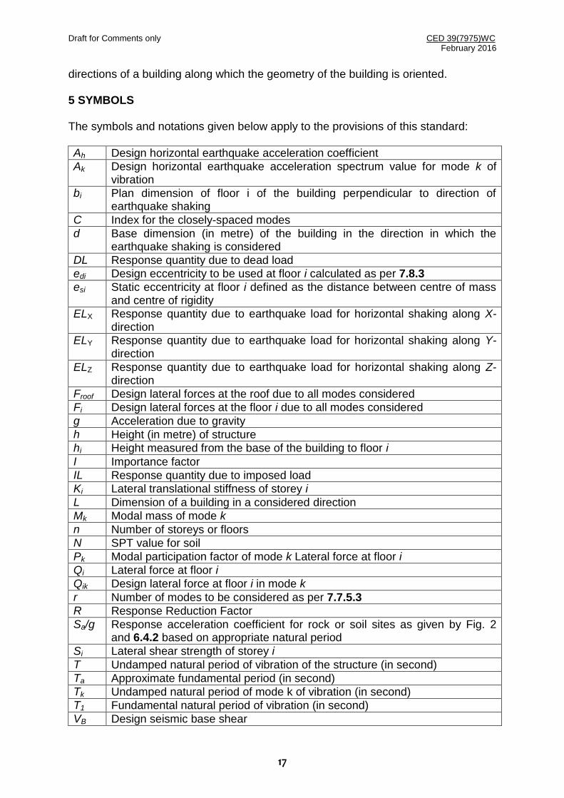
directions of a building along which the geometry of the building is oriented. 5 SYMBOLS The symbols and notations given below apply to the provisions of this standard:
Ah Design horizontal earthquake acceleration coefficient
Ak Design horizontal earthquake acceleration spectrum value for mode k of vibration
bi Plan dimension of floor i of the building perpendicular to direction of earthquake shaking
C Index for the closely-spaced modes
d Base dimension (in metre) of the building in the direction in which the earthquake shaking is considered
DL Response quantity due to dead load
edi Design eccentricity to be used at floor i calculated as per 7.8.3
esi Static eccentricity at floor i defined as the distance between centre of mass and centre of rigidity
ELX Response quantity due to earthquake load for horizontal shaking along X-direction
ELY Response quantity due to earthquake load for horizontal shaking along Y-direction
ELZ Response quantity due to earthquake load for horizontal shaking along Z-direction
Froof Design lateral forces at the roof due to all modes considered
Fi Design lateral forces at the floor i due to all modes considered
g Acceleration due to gravity
h Height (in metre) of structure
hi Height measured from the base of the building to floor i
I Importance factor
IL Response quantity due to imposed load
Ki Lateral translational stiffness of storey i
L Dimension of a building in a considered direction
Mk Modal mass of mode k
n Number of storeys or floors
N SPT value for soil
Pk Modal participation factor of mode k Lateral force at floor i
Qi Lateral force at floor i
Qik Design lateral force at floor i in mode k
r Number of modes to be considered as per 7.7.5.3
R Response Reduction Factor
Sa/g Response acceleration coefficient for rock or soil sites as given by Fig. 2 and 6.4.2 based on appropriate natural period
Si Lateral shear strength of storey i
T Undamped natural period of vibration of the structure (in second)
Ta Approximate fundamental period (in second)
Tk Undamped natural period of mode k of vibration (in second)
T1 Fundamental natural period of vibration (in second)
VB Design seismic base shear
Draft for Comments only CED 39(7975)WC February 2016
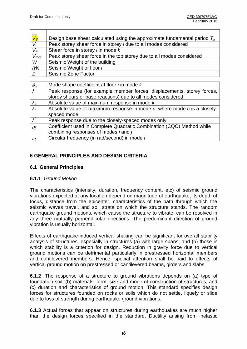
18
VB
Design base shear calculated using the approximate fundamental period Ta
Vi Peak storey shear force in storey i due to all modes considered
Vik Shear force in storey i in mode k
Vroof Peak storey shear force in the top storey due to all modes considered
W Seismic Weight of the building
fWi Seismic Weight of floor i
Z Seismic Zone Factor
ik Mode shape coefficient at floor i in mode k
λ Peak response (for example member forces, displacements, storey forces, storey shears or base reactions) due to all modes considered
λk Absolute value of maximum response in mode k
λc Absolute value of maximum response in mode c, where mode c is a closely-spaced mode
λ* Peak response due to the closely-spaced modes only
ji Coefficient used in Complete Quadratic Combination (CQC) Method while combining responses of modes i and j
i Circular frequency (in rad/second) in mode i
6 GENERAL PRINCIPLES AND DESIGN CRITERIA 6.1 General Principles 6.1.1 Ground Motion The characteristics (intensity, duration, frequency content, etc) of seismic ground vibrations expected at any location depend on magnitude of earthquake, its depth of focus, distance from the epicenter, characteristics of the path through which the seismic waves travel, and soil strata on which the structure stands. The random earthquake ground motions, which cause the structure to vibrate, can be resolved in any three mutually perpendicular directions. The predominant direction of ground vibration is usually horizontal. Effects of earthquake-induced vertical shaking can be significant for overall stability analysis of structures, especially in structures (a) with large spans, and (b) those in which stability is a criterion for design. Reduction in gravity force due to vertical ground motions can be detrimental particularly in prestressed horizontal members and cantilevered members. Hence, special attention shall be paid to effects of vertical ground motion on prestressed or cantilevered beams, girders and slabs. 6.1.2 The response of a structure to ground vibrations depends on (a) type of foundation soil; (b) materials, form, size and mode of construction of structures; and (c) duration and characteristics of ground motion. This standard specifies design forces for structures founded on rocks or soils which do not settle, liquefy or slide due to loss of strength during earthquake ground vibrations. 6.1.3 Actual forces that appear on structures during earthquakes are much higher than the design forces specified in the standard. Ductility arising from inelastic

Draft for Comments only CED 39(7975)WC February 2016
19
material behavior, detailing and overstrength resulting from the additional reserve strength in structures over and above the design strength are relied upon for the deficit in actual and design lateral loads. In other words, earthquake resistant design as per this standard relies on inelastic behaviour of structures. But, the maximum ductility that can be realized in structures is limited. Therefore, structures shall be designed for at least the minimum design lateral force specified in this standard. 6.1.4 Members and connections of reinforced and prestressed concrete structures shall be designed (as per IS 456 and IS 1343) such that premature failure does not occur due to shear or bond. Some provisions for appropriate ductile detailing of RC members are given in IS 13920. Members and their connections of steel structures should be so proportioned that high ductility is obtained in the structure, avoiding premature failure due to elastic or inelastic buckling of any type. Some provisions for appropriate ductile detailing of steel members are given in IS 800. 6.1.5 Soil-Structure Interaction The soil-structure interaction refers to effects of the flexibility of supporting soil-foundation system on the response of structure. The soil-structure interaction may not be considered in the seismic analysis for structures supported on rock or rock-like material. 6.1.6 Equipment and other systems, which are supported at various floor levels of the structure, will be subjected to motions corresponding to vibration at their support points. In important cases, it may be necessary to obtain floor response spectra for design of equipment supports. For details, reference may be made to IS 1893 (Part 4). 6.1.7 Additions to Existing Structures Additions shall be made to existing structures only as follows: (a) An addition that is structurally independent from an existing structure shall be
designed and constructed in accordance with the seismic requirements for new structures.
(b) An addition that is structurally connected to an existing structure shall be designed and constructed such that the entire structure conforms to the seismic force resistance requirements for new structures, unless the following three conditions are complied with: (i) The addition shall comply with the requirements for new structures, (ii) The addition shall not increase the seismic forces in any structural element
of the existing structures by more than 5 percent, unless the capacity of the element subject to the increased force is still in compliance with this standard, and
(iii) The addition shall not decrease the seismic resistance of any structural element of the existing structure unless reduced resistance is equal to or greater than that required for new structures.
Draft for Comments only CED 39(7975)WC February 2016
20
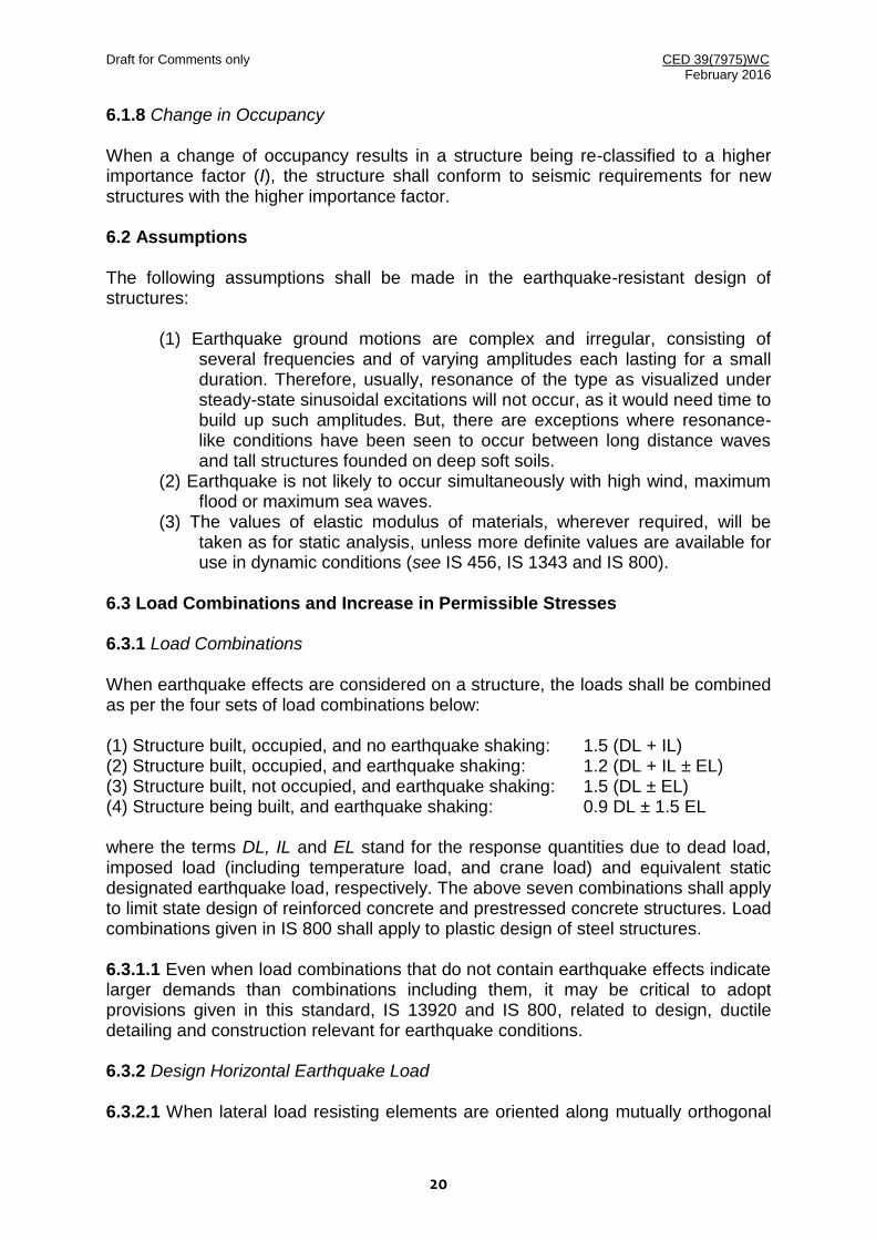
6.1.8 Change in Occupancy When a change of occupancy results in a structure being re-classified to a higher importance factor (I), the structure shall conform to seismic requirements for new structures with the higher importance factor. 6.2 Assumptions The following assumptions shall be made in the earthquake-resistant design of structures:
(1) Earthquake ground motions are complex and irregular, consisting of several frequencies and of varying amplitudes each lasting for a small duration. Therefore, usually, resonance of the type as visualized under steady-state sinusoidal excitations will not occur, as it would need time to build up such amplitudes. But, there are exceptions where resonance-like conditions have been seen to occur between long distance waves and tall structures founded on deep soft soils.
(2) Earthquake is not likely to occur simultaneously with high wind, maximum flood or maximum sea waves.
(3) The values of elastic modulus of materials, wherever required, will be taken as for static analysis, unless more definite values are available for use in dynamic conditions (see IS 456, IS 1343 and IS 800).
6.3 Load Combinations and Increase in Permissible Stresses 6.3.1 Load Combinations When earthquake effects are considered on a structure, the loads shall be combined as per the four sets of load combinations below: (1) Structure built, occupied, and no earthquake shaking: 1.5 (DL + IL) (2) Structure built, occupied, and earthquake shaking: 1.2 (DL + IL ± EL) (3) Structure built, not occupied, and earthquake shaking: 1.5 (DL ± EL) (4) Structure being built, and earthquake shaking: 0.9 DL ± 1.5 EL where the terms DL, IL and EL stand for the response quantities due to dead load, imposed load (including temperature load, and crane load) and equivalent static designated earthquake load, respectively. The above seven combinations shall apply to limit state design of reinforced concrete and prestressed concrete structures. Load combinations given in IS 800 shall apply to plastic design of steel structures. 6.3.1.1 Even when load combinations that do not contain earthquake effects indicate larger demands than combinations including them, it may be critical to adopt provisions given in this standard, IS 13920 and IS 800, related to design, ductile detailing and construction relevant for earthquake conditions. 6.3.2 Design Horizontal Earthquake Load 6.3.2.1 When lateral load resisting elements are oriented along mutually orthogonal

Draft for Comments only CED 39(7975)WC February 2016
21
horizontal direction, structure shall be designed for effects due to full design earthquake load in one horizontal direction at a time, and not in both directions simultaneously. 6.3.2.2 When lateral load resisting elements are not oriented along mutually orthogonal horizontal directions, or when building is torsionally irregular (as per 7.1) about both horizontal axes, structure shall be designed for effects due to full design earthquake load in one horizontal direction plus 30 percent of design earthquake load along other horizontal direction. Thus, the structure should be designed for the following sets of combinations of earthquake load effects:
(1) ± ELX ± 0.3 ELY, and (2) ± 0.3 ELX ± ELY,
where X and Y are two orthogonal horizontal plan directions. Thus, EL in the four sets of load combinations given in 6.3.1 shall be replaced by (ELX ± 0.3 ELY) or (ELY ± 0.3 ELX). This implies that the number of load combinations to be considered will be 13 instead of 7 given in 6.3.1, as given below:
(1) Structure built, occupied, and no earthquake shaking:
1.5 (DL + IL) (2) Structure built, occupied, and earthquake shaking:
1.2 (DL + IL ± (ELX ± 0.3 ELY)) and 1.2 (DL + IL ± (ELY ± 0.3 ELX))
(3) Structure built, not occupied, and earthquake shaking: 1.5 (DL ± (ELX ± 0.3 ELY)) and
1.5 (DL ± (ELY ± 0.3 ELX)) (4) Structure being built, and earthquake shaking:
0.9 DL ± 1.5 (ELX ± 0.3 ELY) and 0.9 DL ± 1.5 (ELY ± 0.3 ELX)
6.3.3 Design Vertical Earthquake Load 6.3.3.1 When effects due to vertical earthquake loads are to be considered, the design vertical force shall be calculated for vertical ground motion as detailed in 6.4.5. 6.3.3.2 Where both horizontal and vertical seismic forces are taken into account, load combination specified in 6.3.4 shall be considered. 6.3.4 Combinations to account for Two or Three Directional Earthquake Ground Shaking 6.3.4.1 When responses from the three earthquake components are to be considered, the responses due to each component may be combined using the assumption that when the maximum response from one component occurs, the responses from the other two components are 30 percent each of their maximum. All possible combinations of three components (ELX, ELY and ELZ) including variations in sign (plus or minus) shall be considered. Thus, the structure should be designed for the following sets of combinations of earthquake load effects:

Draft for Comments only CED 39(7975)WC February 2016
22
(1) ± ELX ± 0.3 ELY ± 0.3 ELZ, (2) ± ELY ± 0.3 ELZ ± 0.3 ELX, and (3) ± ELZ ± 0.3 ELX ± 0.3 ELY,
where X and Y are orthogonal plan directions and Z vertical direction. Thus, EL in the four sets of load combinations given in 6.3.1 shall be replaced by (ELX ± 0.3 ELY ± 0.3 ELZ), (ELY ± 0.3 ELZ ± 0.3 ELX) or (ELZ ± 0.3 ELX ± 0.3 ELY,). This implies that the number of load combinations to be considered will be 25 instead of 7 given in 6.3.1, as given below:
(1) Structure built, occupied, and no earthquake shaking: 1.5 (DL + IL)
(2) Structure built, occupied, and earthquake shaking: 1.2 (DL + IL ± (ELX ± 0.3 ELY ± 0.3 ELZ)) and 1.2 (DL + IL ± (ELY ± 0.3 ELX ± 0.3 E Z))
(3) Structure built, not occupied, and earthquake shaking: 1.5 (DL ± (ELX ± 0.3 ELY ± 0.3 ELZ)) and 1.5 (DL ± (ELY ± 0.3 ELX ± 0.3 ELZ))
(4) Structure being built, and earthquake shaking: 0.9 DL ± 1.5 (ELX ± 0.3 ELY ± 0.3 ELZ) and 0.9 DL ± 1.5 (ELY ± 0.3 ELX ± 0.3 ELZ)
When two dimensional earthquake shaking is required to be considered, even if the building is regular, the combinations given in 6.3.2.2 shall be considered. 6.3.4.2 As an alternative to the procedure in 6.3.4.1, the net response (EL) due to the combined effect of the three components can be obtained by
222
ZYX ELELELEL
Caution may be exercised on loss of sign especially of the axial force, shear force and bending moment quantities, when this procedure is used; it can lead to grossly uneconomical design of structures. 6.3.4.3 Procedure for combining shaking effects given by 6.3.4.1 and 6.3.4.2 apply to the same response quantity (say, bending moment in a column about its major axis, or storey shear force in a frame) due to different components of the ground motion.
6.3.4.4 When components corresponding to only two ground motions (say one horizontal and one vertical, or only two horizontal) are combined, the equations in 6.3.4.1 and 6.3.4.2 should be modified by deleting the term representing the response due to the component of motion not being considered. 6.3.5 Increase in Allowable Pressure in Soils 6.3.5.1 When earthquake forces are included, allowable bearing pressure in soils shall be increased as per Table 1, depending on type of foundation of structure and type of soil.

Draft for Comments only CED 39(7975)WC February 2016
23
6.3.5.2 In soil deposits consisting of submerged loose sands and soils falling under classification SP with corrected standard penetration test N values less than 15 in seismic zones III, IV and V, and less than 10 in Seismic Zone II, the shaking caused by earthquake ground motion may cause liquefaction or excessive total and differential settlements. Such sites should preferably be avoided for locating new settlements or important projects. Otherwise, this aspect of the problem needs to be investigated, and appropriate methods adopted of compaction or stabilization to achieve N values indicated in Note 3 under Table 1. Alternatively, deep pile foundation may be provided and taken to depths well into the layer, which is not likely to liquefy. Also, marine clays and other sensitive clays are known to liquefy due to collapse of soil structure, and will need special treatment according to site condition. Specialist literature may be referred for determining liquefaction potential of a site. A simplified method for evaluation of liquefaction potential is given in Annex F.
Table 1 Percentage Increase in Allowable Bearing Pressure of Soils (Clause 6.3.5.1)
Sl No. Foundation Soil that mainly constitutes foundation
Soil Type I Rock or Hard Soils
Soil Type II Medium or Stiff Soils
Type III Soft Soils
(1) (2) (3) (4) (5)
1. Piles passing through any soil, but resting on Soil Type I 50 50 -
2. Piles not covered under Item 1 above - 25 -
3. Raft foundations 50 50 -
4. Combined or Isolated RCC footings with tie beams 50 25 -
5. Isolated RCC footing without tie beams, or unreinforced strip foundations
50 25 -
6. Well foundations 50 25 -
NOTES 1. The allowable bearing pressure shall be determined in accordance with IS 6403 or IS 1888. 2. If any increase in bearing pressure has already been permitted for forces other than seismic forces, the
total increase in allowable bearing pressure when seismic force is also included shall not exceed the limits specified above.
3. Desirable minimum corrected field values of N: If soils of smaller N values are met than those specified in the table below, soil may be compacted to achieve these values. Alternately, deep pile foundations anchored in stronger strata below should be used.
S.No. Seismic Zone Depth (m) below GL N Values Remarks
i) III, IV and V ≤ 5 ≥ 10
15 25
For values of depths between 5 m and 10 m, linear interpolation is recommended. ii) II (for important
structures only) ≤ 5
> 10 10 20
4. The allowable bearing pressure shall be determined in accordance with IS 6403 or IS 1888, based on the corrected values of N at the founding level as per table below (applicable only for seismic zone II):
S.No. Seismic Zone Depth (m) below GL N Values Remarks
i) II (for important structures only)
≤ 5 > 10
15 20
For values of depths between 5 m and 10 m, linear interpolation is recommended.
5. The piles should be designed for lateral loads neglecting lateral resistance of those soil layers that are liable to liquefy.
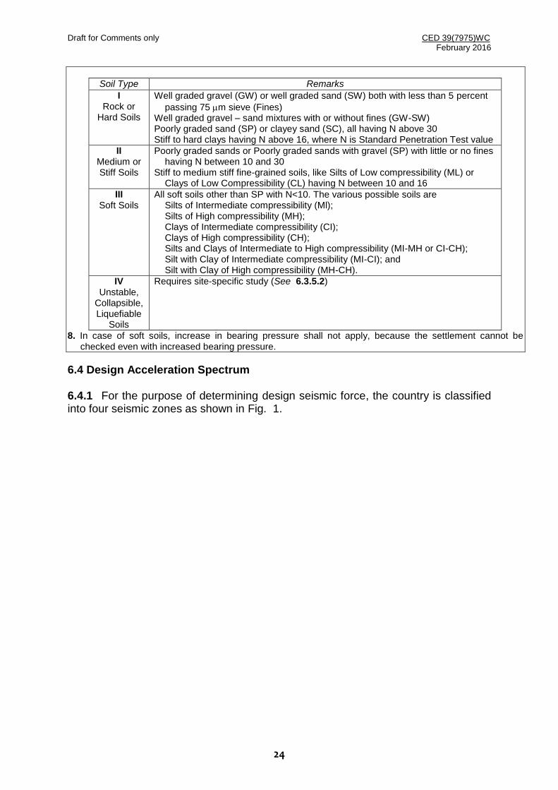
6. IS 1498 and IS 2131 also may be referred for soil notation and corrected N Values. 7. Soils shall be classified in four types as below:
Draft for Comments only CED 39(7975)WC February 2016
24
Soil Type Remarks
I Rock or
Hard Soils
Well graded gravel (GW) or well graded sand (SW) both with less than 5 percent
passing 75 m sieve (Fines) Well graded gravel – sand mixtures with or without fines (GW-SW) Poorly graded sand (SP) or clayey sand (SC), all having N above 30 Stiff to hard clays having N above 16, where N is Standard Penetration Test value
II Medium or Stiff Soils
Poorly graded sands or Poorly graded sands with gravel (SP) with little or no fines having N between 10 and 30
Stiff to medium stiff fine-grained soils, like Silts of Low compressibility (ML) or Clays of Low Compressibility (CL) having N between 10 and 16
III Soft Soils
All soft soils other than SP with N<10. The various possible soils are Silts of Intermediate compressibility (Ml); Silts of High compressibility (MH); Clays of Intermediate compressibility (CI); Clays of High compressibility (CH); Silts and Clays of Intermediate to High compressibility (MI-MH or CI-CH); Silt with Clay of Intermediate compressibility (MI-CI); and Silt with Clay of High compressibility (MH-CH).
IV Unstable,
Collapsible, Liquefiable
Soils
Requires site-specific study (See 6.3.5.2)
8. In case of soft soils, increase in bearing pressure shall not apply, because the settlement cannot be checked even with increased bearing pressure.
6.4 Design Acceleration Spectrum 6.4.1 For the purpose of determining design seismic force, the country is classified into four seismic zones as shown in Fig. 1.

Draft for Comments only CED 39(7975)WC February 2016
25
FIG. 1 SEISMIC ZONES OF INDIA

Draft for Comments only CED 39(7975)WC February 2016
26
6.4.2 The design horizontal seismic coefficient Ah for a structure shall be determined by:
R
gSZIA a
h2
where Z = Seismic zone factor given in Table 2;
/ = Importance factor given in Table 3 for Buildings and in IS 1893 (Parts 2 to 5) for other structures;
R = Response reduction factor given in Parts 1 to 5 of IS 1893 for the corresponding systems, for example, R values for building systems are given in Table 6 of this standard; and
(Sa /g) = Design acceleration coefficient corresponding to 5 percent damping for different
soil types, normalized to peak ground acceleration, corresponding to natural period T of structure considering soil-structure interaction, given by Fig. 2 and the associated expressions below:
sTsT
sT
sTsT
sT
sTsT
sT
g
Sa
00.667.067.1
67.005.2Sites SoilSoft For
00.655.036.1
55.005.2Sites Soil Stiff MediumFor
00.640.01
40.005.2Sites Soil Hardor Rocky For
0.0
0.5
1.0
1.5
2.0
2.5
3.0
0 1 2 3 4 5 6
Natural Period T (s)
Sa/g
Type I: Rock or Hard Soil
Type II: Medium Soil
Type III: Soft Soil
FIG. 2: DESIGN ACCELERATION COEFFICIENT (Sa /g)
(CORRESPONDING TO 5 PERCENT DAMPING) FOR USE IN (A) EQUIVALENT STATIC METHOD, AND
(B) RESPONSE SPECTRUM METHOD

Draft for Comments only CED 39(7975)WC February 2016
27
Table 2 Seismic Zone Factor Z (Clause 6.4.2)
Seismic Zone Factor II III IV V
Z 0.10 0.16 0.24 0.36
Table 3 Importance Factor I
(Clause 6.4.2)
Sl No.
Structure /
1. Important service and community buildings or structures (for example, critical governance buildings, schools), signature structures, monument structures, lifeline and emergency structures (for example, hospitals, telephone exchanges, television stations, radio stations, bus stations, metro rail structure and metro rail stations, railway stations, airports, water main lines and water tanks, food chain structures, fuel stations, electricity stations, fire stations, and bridges), and large community halls (for example, cinema halls, shopping malls, assembly halls and subway stations) and power stations.
1.5
2. Residential or commercial buildings or structures, with occupancy more than 200 persons
1.2
3. All other buildings or structures 1.0 NOTES 1 Owners and design engineers of buildings or structures may choose values of importance factor I more
than those mentioned above. 2 Buildings and structures not covered in items 1 and 2 above may be designed for higher value of
Importance Factor I, depending on economy and strategy (for example, multi-storey buildings having several residential units).
3 This table does not apply to temporary structures (for example, excavations, and scaffolding) that are intended to be in operation only for a short duration.
4 For industrial structures, including those containing hazardous materials, Importance Factor, I shall be taken as per IS 1893 (Part 4).
6.4.3 Effects of design earthquake loads applied on structures can be considered in two ways, namely:
1) Equivalent Static Method, and 2) Dynamic Analysis Method.
In turn, dynamic analysis can be performed in three ways, namely
i) Response Spectrum Method, ii) Modal Time History Method, and iii) Time History Method.
In this standard, Equivalent Static Method, Response Spectrum Method and Time History Method are adopted. Equivalent static method is applicable only for preliminary analysis of any structure, and for analysis of short period structures. 6.4.4 Where a number of modes are to be considered in Response Spectrum Method, Ah as defined in 6.4.2 for each mode k shall be determined using natural
Draft for Comments only CED 39(7975)WC February 2016
28
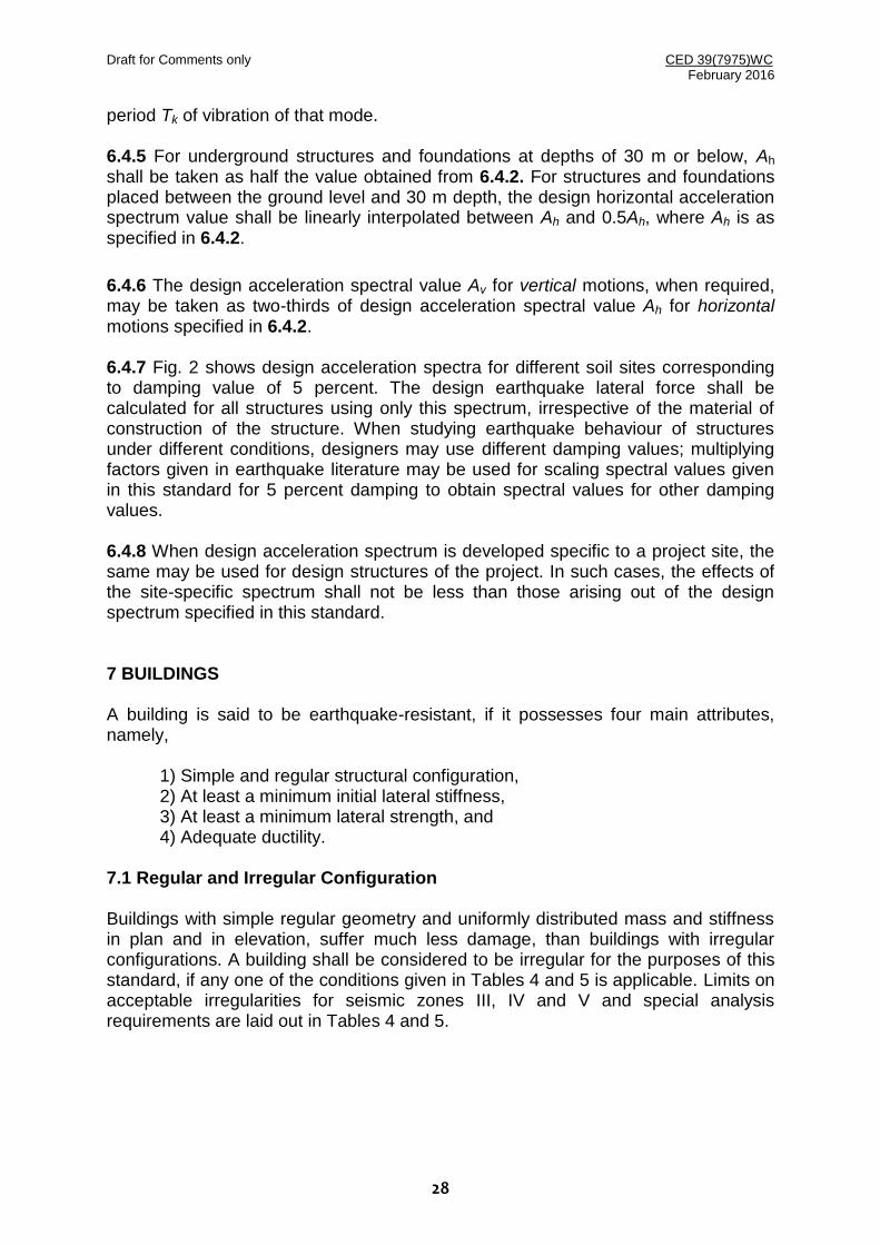
period Tk of vibration of that mode. 6.4.5 For underground structures and foundations at depths of 30 m or below, Ah shall be taken as half the value obtained from 6.4.2. For structures and foundations placed between the ground level and 30 m depth, the design horizontal acceleration spectrum value shall be linearly interpolated between Ah and 0.5Ah, where Ah is as specified in 6.4.2.
6.4.6 The design acceleration spectral value Av for vertical motions, when required, may be taken as two-thirds of design acceleration spectral value Ah for horizontal motions specified in 6.4.2. 6.4.7 Fig. 2 shows design acceleration spectra for different soil sites corresponding to damping value of 5 percent. The design earthquake lateral force shall be calculated for all structures using only this spectrum, irrespective of the material of construction of the structure. When studying earthquake behaviour of structures under different conditions, designers may use different damping values; multiplying factors given in earthquake literature may be used for scaling spectral values given in this standard for 5 percent damping to obtain spectral values for other damping values. 6.4.8 When design acceleration spectrum is developed specific to a project site, the same may be used for design structures of the project. In such cases, the effects of the site-specific spectrum shall not be less than those arising out of the design spectrum specified in this standard. 7 BUILDINGS A building is said to be earthquake-resistant, if it possesses four main attributes, namely,
1) Simple and regular structural configuration, 2) At least a minimum initial lateral stiffness, 3) At least a minimum lateral strength, and 4) Adequate ductility.
7.1 Regular and Irregular Configuration Buildings with simple regular geometry and uniformly distributed mass and stiffness in plan and in elevation, suffer much less damage, than buildings with irregular configurations. A building shall be considered to be irregular for the purposes of this standard, if any one of the conditions given in Tables 4 and 5 is applicable. Limits on acceptable irregularities for seismic zones III, IV and V and special analysis requirements are laid out in Tables 4 and 5.

Draft for Comments only CED 39(7975)WC February 2016
29
Table 4 Definitions of Irregular Buildings – Plan Irregularities (see Fig. 3) (Clause 7.1)
(a) Torsional Irregularity
Usually, a well proportioned building does not twist about its vertical axis, when (a) the stiffness distribution of the vertical elements resisting lateral loads is
balanced in plan according to the distribution of mass in plan (at each storey level); and
(b) the floor slabs are stiff in their own plane (this happens when its plan aspect ratio is less than 3).
A building is said to be torsionally irregular, when maximum horizontal displacement of any floor in the direction of the lateral force at one end of the floor is more than 1.5 times its minimum horizontal displacement at the far end in that direction.
Buildings in Seismic Zones III, IV and V with Torsional Irregularity shall be designed adequately to avoid torsional irregularity.
(b) Re-entrant Corners
A building is said to have a re-entrant corner, when its structural configuration in plan has a projection in a direction of size greater than 15 percent of its overall plan dimension in that direction.
Buildings in Seismic Zones III, IV and V with re-entrant corners shall be re-designed adequately to avoid plan configurations having re-entrant corners.
(c) Floor Slabs having Excessive Cut-Outs or Openings
Floor slabs having cut-outs or openings of area more than 50 percent of the full area of the floor slab, have discontinuity in their in-plane stiffness.
Buildings in Seismic Zones III, IV and V with floor slabs having excessive cut-outs or openings shall be designed adequately to avoid floor slabs with excessive cut-outs or openings.
(d) Out-of-Plane Offsets in Vertical Elements
Out-of-plane offsets in vertical elements resisting lateral loads cause discontinuities and detours in the load path.
Buildings in Seismic Zones III, IV and V with out-of-plane offsets in vertical elements shall be designed adequately to avoid out-of-plane offsets in vertical elements.
(e) Non-Parallel Lateral Force System
A building is said to have non-parallel system when the vertical elements resisting lateral force are not parallel to or symmetric about the two principal orthogonal axes.
Buildings with non-parallel lateral force resisting system shall be analysed under load combinations mentioned in 6.3.2.2.

Draft for Comments only CED 39(7975)WC February 2016
30
(A)
(B)
(C)
Aopening
Atotal
A0 < 0.5Atotal
min
max
maxmin
L
A A
A
A
L A
L1
L2
A

Draft for Comments only CED 39(7975)WC February 2016
31
(D)
(E)
FIG. 3 DEFINITIONS OF IRREGULAR BUILDINGS – PLAN IRREGULARITIES: (A) TORSIONAL IRREGULARITY, (B) RE-ENTRANT CORNERS, (C) FLOOR SLABS WITH EXCESSIVE CUT-OUT OR OPENING,
(D) OUT-OF-PLANE OFFSETS, AND (E) NON-PARALLEL SYSTEM

Draft for Comments only CED 39(7975)WC February 2016
32
Table 5 Definition of Irregular Buildings – Vertical Irregularities (see Fig. 4) (Clause 7.1)
(a) Lateral Stiffness Irregularity in two principal plan directions
Lateral stiffness of beams, columns, braces and structural walls determine the lateral stiffness of a building in each principal plan direction. Lateral storey stiffness of a building in two principal plan directions shall be such that, (a) the first two modes of oscillation are pure translational modes, and (b) the fundamental lateral natural periods of the building in the two principal
plan directions are away from each other by 15 percent of the larger value. Buildings in Seismic Zones III, IV and V with lateral stiffness irregularity in two principal plan directions shall be designed adequately to avoid having close fundamental lateral translational natural periods in each principal plan direction.
(b) Stiffness Irregularity (Soft Storey)
A soft storey is one in which the lateral stiffness is less than that in the storey above. Buildings in seismic zones III, IV and V with stiffness irregularity shall be designed adequately to avoid soft storeys.
(c) Mass Irregularity
Mass irregularity shall be considered to exist, when the seismic weight of any floor is more than 150 percent of that of its adjacent floors. This provision of 150 percent may be relaxed in case of roofs. Buildings in seismic zones III, IV and V with mass irregularity shall be designed by the Dynamic Analysis Method (as per 7.7).
(d) Vertical Geometric Irregularity
Vertical geometric irregularity shall be considered to exist, when the horizontal dimension of the lateral force resisting system in any storey is more than 125 percent of that in its adjacent storey. Buildings in seismic zones III, IV and V with vertical geometric irregularity shall be designed by the Dynamic Analysis Method (as per 7.7).
(e) In-Plane Discontinuity in Vertical Elements Resisting Lateral Force
In-plane discontinuity in vertical elements resisting lateral force shall be considered to exist, when in-plane offset of the lateral force resisting elements is greater than the plan length of those elements. Buildings in seismic zones III, IV and V with in-plane discontinuity in vertical elements resisting lateral force shall be designed adequately to avoid in-plane discontinuity in vertical elements resisting lateral force.
(f) Discontinuity in Capacity (Weak Storey)
A weak storey is one in which the storey lateral strength is less than that in the storey above. Buildings in seismic zones III, IV and V shall be designed adequately to avoid weak storey.
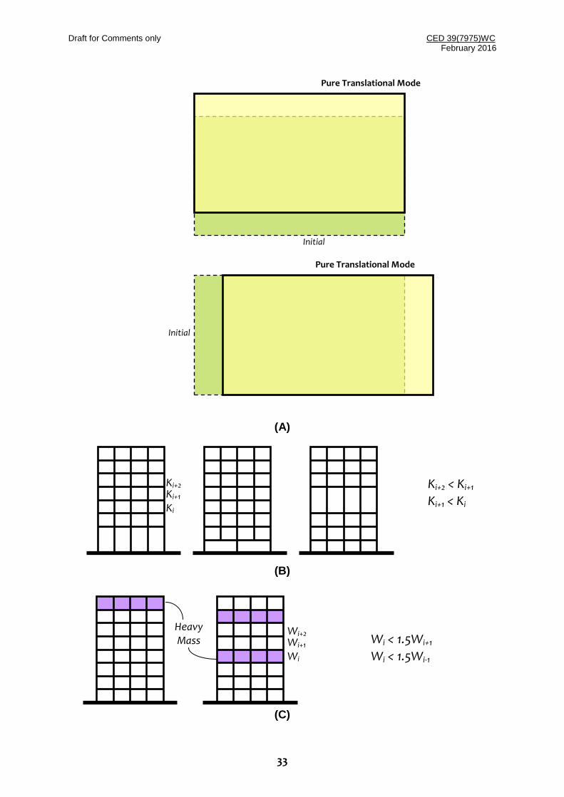
Draft for Comments only CED 39(7975)WC February 2016
33
(A)
(B)
(C)
Initial
Pure Translational Mode
Pure Translational Mode
Initial
Ki+2 Ki+1 Ki
Ki+2 < Ki+1
Ki+1 < Ki
Wi+2 Wi+1 Wi
Wi < 1.5Wi+1
Wi < 1.5Wi-1
Heavy Mass

Draft for Comments only CED 39(7975)WC February 2016
34
(D)
(E)
L
A
L
A A
A < 0.25L A < 0.125L
A A L
L1
L2
L2 < 1.25L1
L1
L2
Storeys 2 and 3
Storey 1
A < 0.1L
Draft for Comments only CED 39(7975)WC February 2016
35
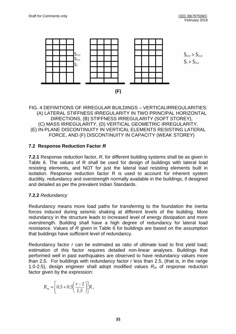
(F)
FIG. 4 DEFINITIONS OF IRREGULAR BUILDINGS – VERTICALIRREGULARITIES: (A) LATERAL STIFFNESS IRREGULARITY IN TWO PRINCIPAL HORIZONTAL
DIRECTIONS, (B) STIFFNESS IRREGULARITY (SOFT STOREY), (C) MASS IRREGULARITY, (D) VERTICAL GEOMETRIC IRREGULARITY,
(E) IN-PLANE DISCONTINUITY IN VERTICAL ELEMENTS RESISTING LATERAL FORCE, AND (F) DISCONTINUITY IN CAPACITY (WEAK STOREY)
7.2 Response Reduction Factor R 7.2.1 Response reduction factor, R, for different building systems shall be as given in Table 6. The values of R shall be used for design of buildings with lateral load resisting elements, and NOT for just the lateral load resisting elements built in isolation. Response reduction factor R is used to account for inherent system ductility, redundancy and overstrength normally available in the buildings, if designed and detailed as per the prevalent Indian Standards. 7.2.2 Redundancy Redundancy means more load paths for transferring to the foundation the inertia forces induced during seismic shaking at different levels of the building. More redundancy in the structure leads to increased level of energy dissipation and more overstrength. Building shall have a high degree of redundancy for lateral load resistance. Values of R given in Table 6 for buildings are based on the assumption that buildings have sufficient level of redundancy. Redundancy factor r can be estimated as ratio of ultimate load to first yield load; estimation of this factor requires detailed non-linear analyses. Buildings that performed well in past earthquakes are observed to have redundancy values more than 2.5. For buildings with redundancy factor r less than 2.5, (that is, in the range 1.0-2.5), design engineer shall adopt modified values Rm of response reduction factor given by the expression:
R51
1r5050Rm
... ,
Si+2 Si+1 Si
Si+1 > Si+2
Si > Si+1

Draft for Comments only CED 39(7975)WC February 2016
36
where R is the response reduction factor given in Table 6.
Table 6 Response Reduction Factor R for Building Systems (Clause 7.2.2)
SlNo.
Lateral Load Resisting System R
Moment Frame Systems
1. RC Buildings with Ordinary Moment Resisting Frame (OMRF)1 3.0
2. RC Buildings with Special Moment-Resisting Frame (SMRF) 5.0
3. Steel Buildings with Ordinary Moment Resisting Frame (OMRF)1 4.0
4. Steel Buildings with Special Moment Resisting Frame (SMRF) 5.0
Braced Frame Systems
5. Steel Buildings with Ordinary Braced Frame with Concentric Braces
4.0
6. Steel Buildings with Special Braced Frame with Concentric Braces 4.5
7. Steel Buildings with Ordinary Braced Frame with Eccentric Braces 4.5
8. Steel Buildings with Special Braced Frame with Eccentric Braces 5.0
Structural Wall Systems
9. Load Bearing Buildings with Masonry Wall
(a) Unreinforced Masonry (designed as per IS 1905) without horizontal RC Seismic Bands
1
1.5
(b) Unreinforced Masonry (designed as per IS 1905) with horizontal RC Seismic Bands 2.0
(b) Unreinforced Masonry (designed as per IS 1905) with horizontal RC Seismic Bands and vertical reinforcing bars at corners of rooms and jambs of openings (with reinforcement as per IS 4326)
2.5
(c) Reinforced Masonry 3.0
(d) Confined Masonry 3.0
10. Load Bearing Buildings with Ordinary RC Structural Walls1 3.0
11. Load Bearing Buildings with Ductile RC Structural Wall 4.0
Dual Systems
12. RC Buildings with Ordinary RC Structural Wall with RC OMRF1 3.0
13. RC Buildings with Ordinary RC Structural Wall with RC SMRF 4.0
14. RC Buildings with Ductile RC Structural Wall with RC OMRF 4.0
15. RC Buildings with Ductile RC Structural Wall with RC SMRF 5.0
Notes 1. RC and Steel structures in Seismic Zones III, IV and V shall be designed to be ductile. Hence, this
system is not allowed in these Seismic Zones. 2. Buildings with shear walls also include buildings having shear walls and frames, but where: (a) Frames are not designed to carry lateral loads, or (b) Frames are designed to carry lateral loads but do not fulfill the requirements of 'Dual Systems'. 3. (a) RC OMRF and Steel OMRF are as defined in 4.15.1. (b) RC SMRF and Steel SMRF are as defined in 4.15.2. (c) Ordinary RC Structural Wall is as defined in 4.19.1. (d) Ductile RC Structural Wall is as defined in 4.19.2. 4. Response reduction factor used in design, damping during extreme shaking, and redundancy
influence the nonlinear behaviour of buildings and structures during strong earthquake shaking. Detailed study is required to understand these influences. Until such time, the values of R given in the table above shall be used with the modification given in 7.2.2.
7.3 Design Imposed Loads for Earthquake Force Calculation 7.3.1 For various loading classes specified in IS 875 (Part 2), design seismic force shall be estimated using full dead load plus percentage of imposed load as given in
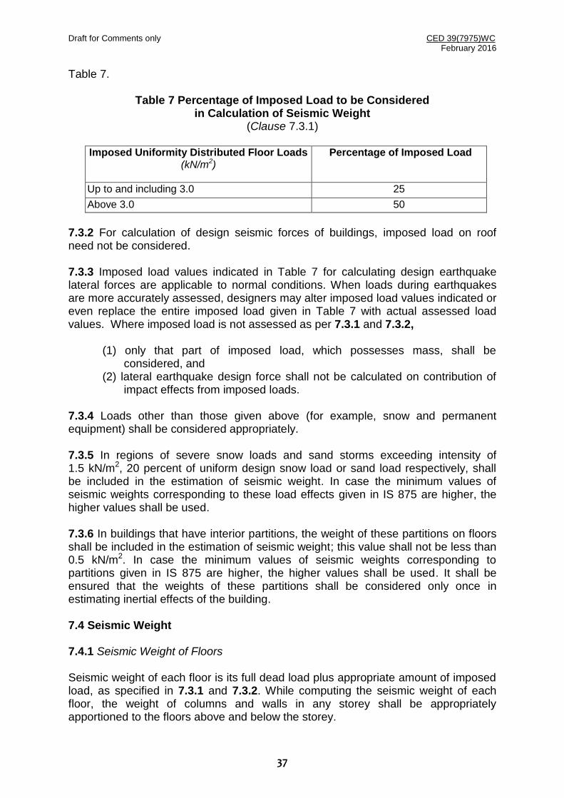
Draft for Comments only CED 39(7975)WC February 2016
37
Table 7.
Table 7 Percentage of Imposed Load to be Considered in Calculation of Seismic Weight
(Clause 7.3.1)
Imposed Uniformity Distributed Floor Loads (kN/m2)
Percentage of Imposed Load
Up to and including 3.0 25
Above 3.0 50
7.3.2 For calculation of design seismic forces of buildings, imposed load on roof need not be considered. 7.3.3 Imposed load values indicated in Table 7 for calculating design earthquake lateral forces are applicable to normal conditions. When loads during earthquakes are more accurately assessed, designers may alter imposed load values indicated or even replace the entire imposed load given in Table 7 with actual assessed load values. Where imposed load is not assessed as per 7.3.1 and 7.3.2,
(1) only that part of imposed load, which possesses mass, shall be considered, and
(2) lateral earthquake design force shall not be calculated on contribution of impact effects from imposed loads.
7.3.4 Loads other than those given above (for example, snow and permanent equipment) shall be considered appropriately. 7.3.5 In regions of severe snow loads and sand storms exceeding intensity of 1.5 kN/m2, 20 percent of uniform design snow load or sand load respectively, shall be included in the estimation of seismic weight. In case the minimum values of seismic weights corresponding to these load effects given in IS 875 are higher, the higher values shall be used. 7.3.6 In buildings that have interior partitions, the weight of these partitions on floors shall be included in the estimation of seismic weight; this value shall not be less than 0.5 kN/m2. In case the minimum values of seismic weights corresponding to partitions given in IS 875 are higher, the higher values shall be used. It shall be ensured that the weights of these partitions shall be considered only once in estimating inertial effects of the building. 7.4 Seismic Weight 7.4.1 Seismic Weight of Floors Seismic weight of each floor is its full dead load plus appropriate amount of imposed load, as specified in 7.3.1 and 7.3.2. While computing the seismic weight of each floor, the weight of columns and walls in any storey shall be appropriately apportioned to the floors above and below the storey.

Draft for Comments only CED 39(7975)WC February 2016
38
7.4.2 Seismic Weight of Buildings Seismic weight of the whole building is the sum of seismic weights of all floors. 7.4.3 Any weight supported in between storeys shall be distributed to floors above and below in inverse proportion to its distance from the floors. 7.5 Design Lateral Force 7.5.1 Buildings and portions there of shall be designed and constructed, to resist at least the effects of design lateral force specified in 7.6.1. But, regardless of design earthquake forces, buildings shall have lateral load resisting systems capable of
resisting a horizontal force not less than percent of the seismic weight of the building as shown in Table 8. This load may be applied at different floor levels in proportion to the seismic weight of respective floors.
Table 8 At least the minimum design earthquake horizontal lateral force for which all buildings should be designed
(Clause 7.5.1)
Seismic Zone
%)
II 0.7
III 1.1
IV 1.6
V 2.4
7.5.2 The design lateral force shall first be computed for the building as a whole. This design lateral force shall be distributed to the various floor levels at the corresponding center of mass. In turn, this design seismic force at each floor level shall be distributed to individual lateral load resisting elements depending on the floor diaphragm action. 7.5.3 The value of damping shall be taken as 5percent of critical damping for the purposes of both Equivalent Static Method (as per 7.6) and Dynamic Analysis Method (as per 7.7) for buildings of all materials (namely steel, reinforced concrete or masonry). 7.6 Equivalent Static Method This method shall be applicable to: 1) Regular buildings with height less than 48 m, and 2) Regular buildings with height greater than 48 m and fundamental translational
natural period less than 3.5 s. 7.6.1 The total design seismic base shear force (VB) along any principal direction of a building shall be determined by:
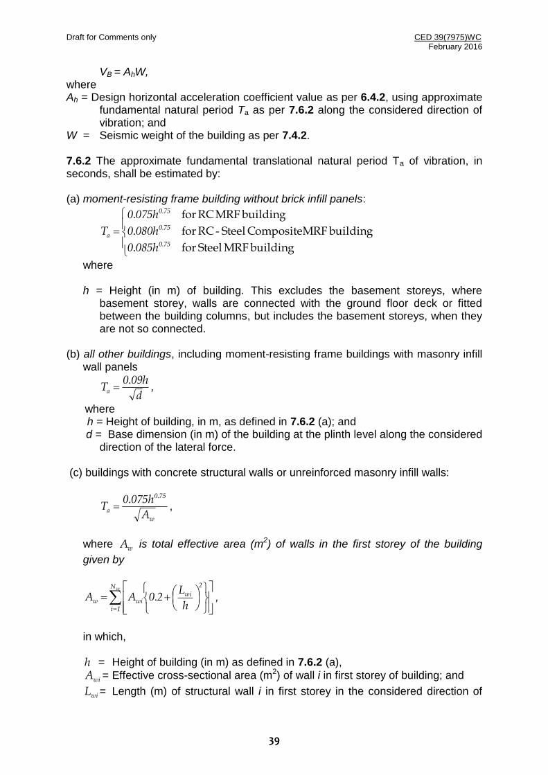
Draft for Comments only CED 39(7975)WC February 2016
39
VB = AhW, where Ah = Design horizontal acceleration coefficient value as per 6.4.2, using approximate
fundamental natural period Ta as per 7.6.2 along the considered direction of vibration; and
W = Seismic weight of the building as per 7.4.2. 7.6.2 The approximate fundamental translational natural period Ta of vibration, in seconds, shall be estimated by: (a) moment-resisting frame building without brick infill panels:
building MRF Steel for.
building MRF Composite Steel-RC for.
building MRF RC for.
.
.
.
750
750
750
a
h0850
h0800
h0750
T
where h = Height (in m) of building. This excludes the basement storeys, where
basement storey, walls are connected with the ground floor deck or fitted between the building columns, but includes the basement storeys, when they are not so connected.
(b) all other buildings, including moment-resisting frame buildings with masonry infill
wall panels
d
h090Ta
. ,
where h = Height of building, in m, as defined in 7.6.2 (a); and
d = Base dimension (in m) of the building at the plinth level along the considered direction of the lateral force.
(c) buildings with concrete structural walls or unreinforced masonry infill walls:
w
750
aA
h0750T
.. ,
where wA is total effective area (m2) of walls in the first storey of the building
given by
wN
1i
2
wiwiw
h
L20AA . ,
in which, h = Height of building (in m) as defined in 7.6.2 (a),
wiA = Effective cross-sectional area (m2) of wall i in first storey of building; and
wiL = Length (m) of structural wall i in first storey in the considered direction of

Draft for Comments only CED 39(7975)WC February 2016
40
lateral forces, and Nw= Number of walls in the considered direction of lateral forces. The value of hLwi to be used in this equation shall not exceed 0.9.
7.6.3 The design base shear (VB) computed in 7.6.1 shall be distributed along the height of the building and in plan at each floor level as below: (a) Vertical Distribution of Base Shear to Different Floor Levels
The design base shear VB computed in 7.6.1 shall be distributed along the height of the building as per the following expression:
Bn
1j
2jj
2ii
i V
hW
hWQ
,
where Q i = Design lateral force at floor i, Wi = Seismic weight of floor i, hi = Height of floor i measured from base, and n = Number of storeys in building, that is, number of levels at which masses
are located.
(b) In-Plan Distribution of Design Lateral Force at Floor i to Different Lateral Force Resisting Elements
The Design Storey Shear in any storey shall be calculated by summing the Design Lateral Forces at all floor above that storey. In buildings whose floors are capable of providing rigid horizontal diaphragm action in their own plane, the Design Storey Shear shall be distributed to the various vertical elements of lateral force resisting system in proportion to the lateral stiffness of these vertical elements. In buildings whose floor diaphragms cannot provide rigid horizontal diaphragm action in their own plane, Design Storey Shear shall be distributed to the various vertical elements of lateral force resisting system considering the in-plane flexibility of the diaphragms. A floor diaphragm shall be considered to be flexible, if it deforms such that the maximum lateral displacement measured from the chord of the deformed shape at any point of the diaphragm is more than 1.5 times the average displacement of the entire diaphragm. Usually, reinforced concrete monolithic slab-beam floors or those consisting of prefabricated /precast elements with reasonable reinforced screed (at least a minimum of 50 mm on floors and of 75 mm on roof, with minimum reinforcement of 6 mm bars spaced at 150 mm centers) as topping, can be considered to be providing rigid diaphragm action.
7.7 Dynamic Analysis Method 7.7.1 Linear dynamic analysis shall be performed to obtain the design lateral force
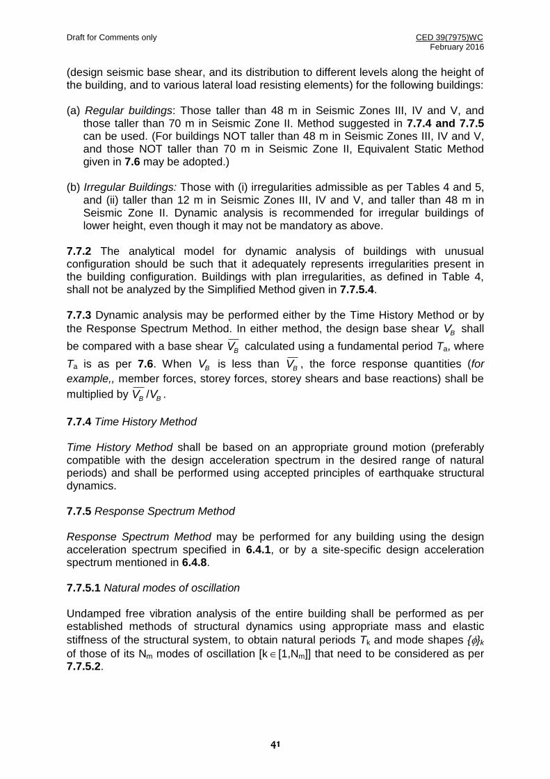
Draft for Comments only CED 39(7975)WC February 2016
41
(design seismic base shear, and its distribution to different levels along the height of the building, and to various lateral load resisting elements) for the following buildings: (a) Regular buildings: Those taller than 48 m in Seismic Zones III, IV and V, and
those taller than 70 m in Seismic Zone II. Method suggested in 7.7.4 and 7.7.5 can be used. (For buildings NOT taller than 48 m in Seismic Zones III, IV and V, and those NOT taller than 70 m in Seismic Zone II, Equivalent Static Method given in 7.6 may be adopted.)
(b) Irregular Buildings: Those with (i) irregularities admissible as per Tables 4 and 5,
and (ii) taller than 12 m in Seismic Zones III, IV and V, and taller than 48 m in Seismic Zone II. Dynamic analysis is recommended for irregular buildings of lower height, even though it may not be mandatory as above.
7.7.2 The analytical model for dynamic analysis of buildings with unusual configuration should be such that it adequately represents irregularities present in the building configuration. Buildings with plan irregularities, as defined in Table 4, shall not be analyzed by the Simplified Method given in 7.7.5.4. 7.7.3 Dynamic analysis may be performed either by the Time History Method or by
the Response Spectrum Method. In either method, the design base shear BV shall
be compared with a base shear BV calculated using a fundamental period Ta, where
Ta is as per 7.6. When BV is less than BV , the force response quantities (for
example,, member forces, storey forces, storey shears and base reactions) shall be
multiplied by BV / BV .
7.7.4 Time History Method Time History Method shall be based on an appropriate ground motion (preferably compatible with the design acceleration spectrum in the desired range of natural periods) and shall be performed using accepted principles of earthquake structural dynamics. 7.7.5 Response Spectrum Method Response Spectrum Method may be performed for any building using the design acceleration spectrum specified in 6.4.1, or by a site-specific design acceleration spectrum mentioned in 6.4.8. 7.7.5.1 Natural modes of oscillation Undamped free vibration analysis of the entire building shall be performed as per established methods of structural dynamics using appropriate mass and elastic
stiffness of the structural system, to obtain natural periods Tk and mode shapes {}k
of those of its Nm modes of oscillation [k[1,Nm]] that need to be considered as per 7.7.5.2.

Draft for Comments only CED 39(7975)WC February 2016
42
7.7.5.2 Number of Modes to be considered The number of modes Nm to be used in the analysis for earthquake shaking along a considered direction, should be such that the sum total of modal masses of these modes considered is at least 90percent of the total seismic mass. If modes with natural frequencies beyond 33 Hz are to be considered, the modal combination shall be carried out only for modes with natural frequency less than 33 Hz; the effect of modes with natural frequencies more than 33 Hz shall be included by the Missing Mass Correction procedure following established principles of structural dynamics. If justified by rigorous analyses, designers may use a cut off frequency other than 33 Hz. 7.7.5.3 Combination of Modes (a) Peak response quantities (for example, member forces, displacements, storey
forces, storey shears, and base reactions) may be combined as per Complete Quadratic Combination (CQC) Method, as below
m mN
1i
N
1jjiji
where
= Estimate of Peak response quantity,
i = Response quantity in mode i (with sign),
j = Response quantity in mode j (with sign),
i j = Cross-modal correlation co-efficient given by
,
.
2222
512
ij141
18
Nm = Number of modes considered,
= Modal damping coefficient ratio shall be taken as 0.05,
= Natural Frequency ratio = ,i
j
j = Circular Natural Frequency in mode j, and
i = Circular Natural Frequency in mode i.
(b) Alternatively, the peak response quantities may be combined as follows:
If building does not have closely-spaced modes, then net peak response quantity due to all modes considered shall be estimated as:
,1
2
mN
kk
Where
k = Peak response quantity in mode k, and

Draft for Comments only CED 39(7975)WC February 2016
43
Nm = Number of modes considered.
If building has a few closely-spaced modes, then net peak response quantity * due to these closely space modes alone shall be obtained as :
,* c
c
where
c = Peak response quantity in closely spaced mode c. The summation is for
closely spaced modes only. Then, this peak response quantity * due to
closely spaced modes is combined with those of remaining well-separated modes by method described above.
7.7.5.4 Simplified Method of Dynamic Analysis of Buildings Regular buildings may be analysed as a system of masses lumped at the floor levels with each mass having one degree of freedom, that of lateral displacement in the direction under consideration. In such a case, the following expressions shall hold in the computation of the various quantities: (a) Modal Mass: Modal mass Mk of mode k is given by
,
n
1i
2iki
2n
1iiki
k
Wg
W
M
where g = Acceleration due to gravity,
ik = Mode shape coefficient at floor i in modek ,
iW = Seismic weight of floor i of the structure, and
n = Number of floors of the structure. (b) Mode Participation Factor: Mode Participation Factor Pk of mode k is given by:
,
n
1i
2iki
n
1iiki
k
W
W
P
(c) Design Lateral Force at Each Floor in Each Mode: Peak Lateral Force ikQ at floor
i in mode k is given by: ikikkik WPAQ
where Ak = Design horizontal acceleration spectrum value as per 6.4.2 using natural
period of vibration Tk of mode k obtained from Dynamic Analysis. (d) Storey Shear Forces in Each Mode: Peak shear force ikV acting in storey i in
mode k is given by:
Draft for Comments only CED 39(7975)WC February 2016
44
n
1ijikik QV
(e) Storey Shear Force due to All Modes Considered: Peak storey shear force iV in
storey i due to all modes considered, shall be obtained by combining those due to each mode in accordance with 7.7.5.3.
(f) Lateral Forces at Each Storey due to All Modes Considered: Design lateral forces
Froof at roof level and iF at level of floor i shall be obtained as:
roofroof VF , and
1iii VVF .
7.8 Torsion 7.8.1 Structural configurations of buildings be so chosen and their members sizes so proportioned, such that the first two fundamental natural modes are pure translational modes of oscillation. The fundamental natural periods of the first two modes shall be away from each other preferably by at least 15percent of the larger value. 7.8.2 Provision shall be made in all buildings for increase in shear forces on the lateral force resisting elements resulting from twisting about the vertical axis of the building, arising due to eccentricity between the centre of mass and centre of stiffness at the floor levels. The design forces calculated as in 7.6 and 7.7.5, shall be applied at the displaced centre of mass so as to cause design eccentricity (as given by 7.8.3) between the displaced centre of mass and centre of stiffness. 7.8.3 Design Eccentricity The design eccentricity edi to be used at floor i shall be taken as:
,.
..
isi
isi
di b0500e
b050e51e
whichever gives the more severe effect on lateral force resisting elements, where
sie = Static eccentricity at floor i
= Distance between centre of mass and centre of stiffness, and
ib = Floor plan dimension of floor i, perpendicular to the direction of force.
The factor 1.5 represents dynamic amplification factor, and 0.05bi represents the extent of accidental eccentricity. 7.9 RC Frame Buildings with Unreinforced Masonry Infill Walls 7.9.1 In RC Buildings with moment resisting frames and unreinforced masonry (URM) infill walls, variation of storey stiffness and storey strength shall be examined along the height of the building considering in-plane stiffness and strength of URM infill walls. If storey stiffness and strength variations along the height of the building render it to be irregular as per Table 5, the irregularity shall be corrected especially in
Draft for Comments only CED 39(7975)WC February 2016
45
seismic zones III, IV and V. 7.9.2 The estimation of in-plane stiffness and strength of URM infill walls shall be based on provisions given in this Clause. 7.9.2.1 The modulus of elasticity Em (in MPa) of masonry infill wall shall be taken as: mm f550E
where mf is the compressive strength of masonry prism (in MPa) obtained as per
IS 1905 or given by expression
3600m
640bm ff4330f ...
in which
bf
= Compressive strength of brick along its thickness (in MPa) and
0mf = Compressive strength of mortor (in MPa)
7.9.2.2 URM infill walls shall be modeled by using equivalent diagonal struts as below: (a) Ends of diagonal struts shall be considered to be pin-jointed to RC frame. (b) For URM infill walls without any opening, width wds of equivalent diagonal strut
shall be taken as one-third of diagonal length d of the URM infill wall (Fig. 5). (c) For URM infill walls with openings, width wdo of equivalent diagonal strut shall be
taken as:
dswdo ww
where
w = Reduction factor, which accounts for openings in infill. For walls with a
central opening, ρw shall be taken as
40.00
40.005.05.21
05.01
r
rr
r
w
Aif
AifA
Aif
,
where Ar = Opening Area Ratio
= Area of Opening / Total Area of URM Infill Wall Panel. (d) Thickness of the equivalent diagonal strut shall be taken as thickness of original
URM infill wall. (e) RC frame members shall be designed to support vertical gravity loads, including
weight of masonry infill walls, without any assistance from the masonry infill walls. Also, it shall be ensured that the frame alone shall be capable of resisting at least 50percent of the design lateral seismic force.

Draft for Comments only CED 39(7975)WC February 2016
46
FIG. 5: DETAILS OF EQUIVALENT DIAGONAL STRUT OF UNREINFORCED
MASONRY INFILL WALL 7.10 RC FRAME BUILDINGS WITH OPEN STOREYS 7.10.1 RC moment resisting frame buildings, which have parking spaces in any storey(s) and without Unreinforced Masonry (URM) infill walls in the same storey(s), are known to have flexible and weak storeys in the storey(s) as per Table 5. Such moment frame buildings shall be provided necessarily with RC Structural Walls in select bays of moment resisting frames along both plan directions as per requirements laid down under 7.10. 7.10.2 The RC Structural Walls shall be: (a) founded on properly designed foundations, (b) continuous over the full height of the building, and (c) integrally connected to the moment resisting frame of the building. 7.10.3 The RC Structural Walls shall be designed (that is, the number, location, length, thickness and detailing of the RC walls) such that the building does NOT have (a) Torsional irregularity in plan. In assessing this, lateral stiffness shall be included
Lds
F
F
wds
Draft for Comments only CED 39(7975)WC February 2016
47
of all elements that resist lateral actions at all levels of the building; (b) Lateral stiffness in the open storey(s) less than 95percent of that in the storey
above; and (c) Lateral strength in the open storey(s) less than 90percent of that in the storey
above.
7.10.4 The RC Structural Wall Plan Density sw of the building shall be at least the
values given in Table 9. The values of sw of RC Structural Walls indicated in Table 9 can be adopted even in regular buildings that do not have open storey(s).
Table 9 Minimum Structural Wall Plan Density to be ensured in RC Frame Buildings with Open Storey(s)
(Clause 7.10.4)
Seismic Zone Structural Wall Plan Density sw %)
II 2
III 4
IV 6
V 6
7.10.5 RC Structural Walls in buildings located in Seismic Zones III, IV, and V shall be designed and detailed to comply with all requirements of IS 13920. 7.11 Deformation 7.11.1 Storey Drift Limitation 7.11.1.1 Storey drift in any storey shall not exceed 0.004 times the storey height, due to specified design lateral force with partial safety factor for loads taken as 1.0 for all load combinations given in 6.3.1. 7.11.1.2 In 7.7.2 and 7.7.3, displacement estimates from Response Spectrum Method of analysis shall be used without incorporating the 7.7.3; displacement estimates from Equivalent Static Method of analysis shall be used as such with no modification. 7.11.2 Deformation Capability of Non-Seismic Members For buildings located in seismic zones IV and V, it shall be ensured that structural components, that are not a part of seismic force resisting system in considered direction of ground motion but are monolithically connected, do not lose their vertical load-carrying capacity under induced bending moments and shear forces resulting from storey deformations equal to R times storey displacements calculated as per 7.10.1, where R is specified in Table 6. 7.11.3 Separation between Adjacent Units Two adjacent buildings, or two adjacent units of the same building with separation joint between them, shall be separated by a distance equal to R times sum of storey displacements calculated as per 7.11.1 of each of the buildings/units, to avoid pounding as the buildings/units oscillate towards each other.
Draft for Comments only CED 39(7975)WC February 2016
48
7.12 Miscellaneous 7.12.1 Foundations Isolated RC footings without tie beams or unreinforced strip foundations, shall not be adopted in buildings rested on soft soils (with corrected N<10). Use of foundations vulnerable to significant differential settlement due to ground shaking shall be avoided in buildings located in seismic zones III, IV and V. Individual spread footings or pile caps shall be interconnected with ties (See 5.3.4.1 of IS 4326), except when individual spread footings are directly supported on rock, in buildings located in seismic Zones IV and V. All ties shall be capable of carrying, in tension and in compression, an axial force equal to Ah/4 times the larger of the column or pile cap load, in addition to the otherwise computed forces, subject to a minimum of 5percent of larger of column or pile cap loads. Here, Ah is as per 6.4.2. Piles shall be designed and constructed to withstand maximum imposed curvature from earthquake ground motions and structural response. Design of anchorage of piles into the pile cap shall consider combined effects, including that of axial forces due to uplift and bending moments due to fixity to pile cap. 7.12.2 Cantilever Projections 7.12.2.1 Vertical Projections Small-sized facilities (like towers, tanks, parapets, smoke stacks/chimneys) and other vertical cantilever projections attached to buildings and projecting above the roof, shall be designed and checked for stability for five times the design horizontal seismic coefficient Ah specified in 6.4.2. In the analysis of the building, weights of these projecting elements shall be lumped with the roof weight. 7.12.2.2 Horizontal Projections All horizontal projections (like brackets, cornices and balconies) shall be designed and checked for stability for five times the design vertical coefficient specified in 6.4.2. 7.12.2.3 The increased design forces specified in 7.12.2.1 and 7.12.2.2 are only for designing the projecting parts and their connections with the main structures, and NOT for the design of the main structure. 7.12.3 Compound Walls Compound walls shall be designed for the design horizontal coefficient of Z/2. 7.12.4 Connections between Parts All small items and objects of a building shall be tied to the building or to each other to act as single unit, except those between the separation joints and seismic joints. These connections shall be made capable of transmitting the forces induced in them, but not less than 0.05 times weight of total dead and imposed load reactions; frictional resistance shall not be relied upon in these calculations.

Draft for Comments only CED 39(7975)WC February 2016
49
Annex A ( Foreword )
MAP SHOWING EPICENTRES OF PAST EARTHQUAKES IN INDIA
(From Catalog of 2015)

Draft for Comments only CED 39(7975)WC February 2016
50
Annex B ( Foreword )
MAP SHOWING PRINCIPAL TECTONIC FEATURES IN INDIA
(From Catalog of 2001)

Draft for Comments only CED 39(7975)WC February 2016
51
Annex C ( Foreword )
MAP OF INDIA SHOWING PRINCIPAL LITHOLOGICAL GROUPS
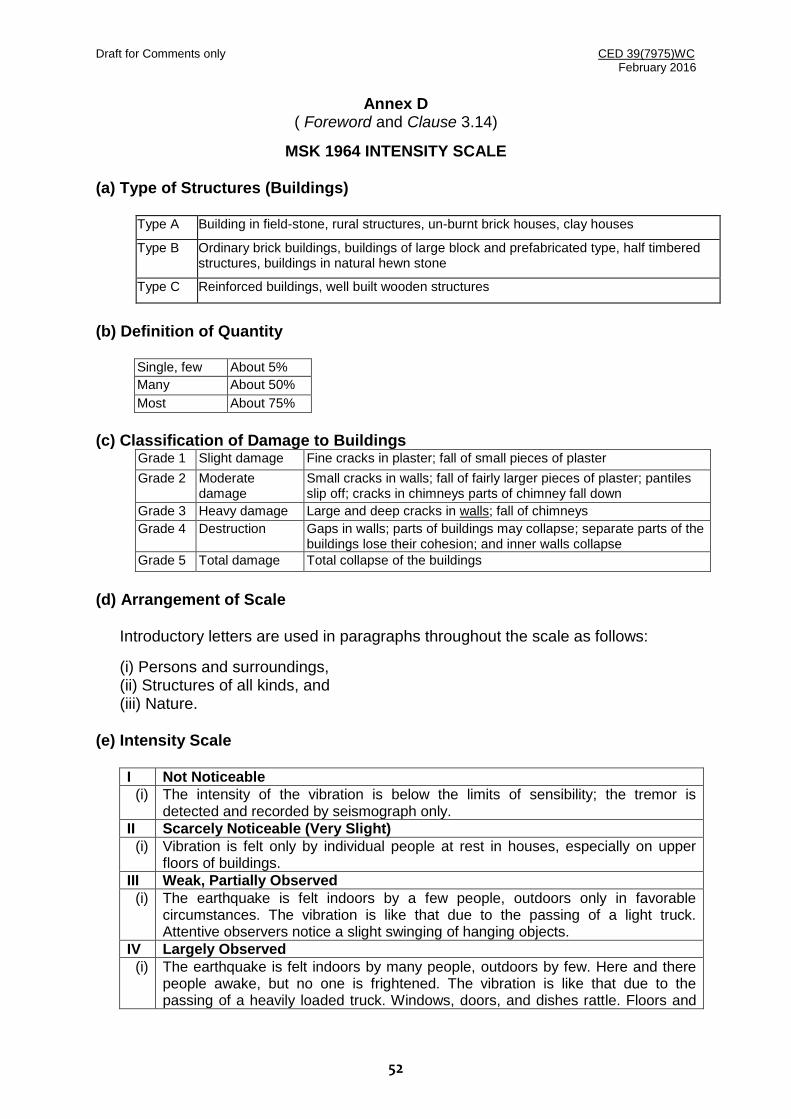
Draft for Comments only CED 39(7975)WC February 2016
52
Annex D ( Foreword and Clause 3.14)
MSK 1964 INTENSITY SCALE
(a) Type of Structures (Buildings)
Type A Building in field-stone, rural structures, un-burnt brick houses, clay houses
Type B Ordinary brick buildings, buildings of large block and prefabricated type, half timbered structures, buildings in natural hewn stone
Type C Reinforced buildings, well built wooden structures
(b) Definition of Quantity
Single, few About 5%
Many About 50%
Most About 75%
(c) Classification of Damage to Buildings
Grade 1 Slight damage Fine cracks in plaster; fall of small pieces of plaster
Grade 2 Moderate damage
Small cracks in walls; fall of fairly larger pieces of plaster; pantiles slip off; cracks in chimneys parts of chimney fall down
Grade 3 Heavy damage Large and deep cracks in walls; fall of chimneys
Grade 4 Destruction Gaps in walls; parts of buildings may collapse; separate parts of the buildings lose their cohesion; and inner walls collapse
Grade 5 Total damage Total collapse of the buildings
(d) Arrangement of Scale
Introductory letters are used in paragraphs throughout the scale as follows:
(i) Persons and surroundings, (ii) Structures of all kinds, and (iii) Nature.
(e) Intensity Scale
I Not Noticeable
(i) The intensity of the vibration is below the limits of sensibility; the tremor is detected and recorded by seismograph only.
II Scarcely Noticeable (Very Slight)
(i) Vibration is felt only by individual people at rest in houses, especially on upper floors of buildings.
III Weak, Partially Observed
(i) The earthquake is felt indoors by a few people, outdoors only in favorable circumstances. The vibration is like that due to the passing of a light truck. Attentive observers notice a slight swinging of hanging objects.
IV Largely Observed
(i) The earthquake is felt indoors by many people, outdoors by few. Here and there people awake, but no one is frightened. The vibration is like that due to the passing of a heavily loaded truck. Windows, doors, and dishes rattle. Floors and

Draft for Comments only CED 39(7975)WC February 2016
53
walls crack. Furniture begins to shake. Hanging objects swing slightly. Liquid in open vessels are slightly disturbed. In standing motor cars the shock is noticeable.
V Awakening
(i) The earthquake is felt indoors by all, outdoors by many. Many people awake. A few run outdoors. Animals become uneasy. Buildings tremble throughout. Hanging objects swing considerably. Pictures knock against walls or swing out of place. Occasionally pendulum clocks stop. Unstable objects overturn or shift. Open doors and windows are thrust open and slam back again. Liquids spill in small amounts from well-filled open containers. The sensation of vibration is like that due to heavy objects falling inside the buildings.
(ii) Slight damages in buildings of Type A are possible.
(iii) Slight waves on standing water. Sometimes changes in flow of springs.
VI Frightening
(i) Felt by most indoors and outdoors. Many people in buildings are frightened and run outdoors. A few persons loose their balance. Domestic animals run out of their stalls. In few instances, dishes and glassware may break, and books fall down, pictures move, and unstable objects overturn. Heavy furniture may possibly move and small steeple bells may ring.
(ii) Damage of Grade 1 is sustained in single buildings of Type B and in many of Type A. Damage in some buildings of Type A is of Grade 2.
(iii) Cracks up to widths of 1cm possible in wet ground; in mountains occasional landslips: change in flow of springs and in level of well water are observed.
VII Damage of Buildings
(i) Most people are frightened and run outdoors. Many find it difficult to stand. The vibration is noticed by persons driving motor cars. Large bells ring.
(ii) In many buildings of Type C damage of Grade 1 is caused; in many buildings of Type B damage is of Grade 2. Most buildings of Type A suffer damage of Grade 3, few of Grade 4. in single instances, landslides of roadway on steep slopes: crack in roads; seams of pipelines damaged; cracks in stone walls.
(iii) Waves are formed on water, and is made turbid by mud stirred up. Water levels in wells change, and the flow of springs changes. Some times dry springs have their flow resorted and existing springs stop flowing. In isolated instances parts of sand and gravelly banks slip off.
VIII Destruction of Buildings
(i) Fright and panic; also persons driving motor cars are disturbed, Here and there branches of trees break off. Even heavy furniture moves and partly overturns. Hanging lamps are damaged in part.
(ii) Most buildings of Type C suffer damage of Grade 2, and few of Grade 3, Most buildings of Type B suffer damage of Grade 3. Most buildings of Type A suffer damage of Grade 4. Occasional breaking of pipe seams. Memorials and monuments move and twist. Tombstones overturn. Stone walls collapse.
(iii) Small landslips in hollows and on banked roads on steep slopes; cracks in ground up to widths of several centimeters. Water in lakes become turbid. New reservoirs come into existence. Dry wells refill and existing wells become dry. In many cases, change in flow and level of water is observed.
IX General Damage of Buildings
(i) General panic; considerable damage to furniture. Animals run to and fro in confusion and cry.
(ii) Many buildings of Type C suffer damage of Grade 3, and a few of Grade 4. Many buildings of Type B show a damage of Grade 4 and a few of Grade 5. Many buildings of Type A suffer damage of Grade 5. Monuments and columns fall. Considerable damage to reservoirs; underground pipes partly broken. In individual cases, railway lines are bent and roadway damaged.

Draft for Comments only CED 39(7975)WC February 2016
54
(iii) On flat land overflow of water, sand and mud is often observed. Ground cracks to widths of up to 10 cm, on slopes and river banks more than 10 cm. Further more, a large number of slight cracks in ground; falls of rock, many land slides and earth flows; large waves in water. Dry wells renew their flow and existing wells dry up.
X General Destruction of Buildings
(ii) Many buildings of Type C suffer damage of Grade 4, and a few of Grade 5. Many buildings of Type B show damage of Grade 5. Most of Type A has destruction of Grade 5. Critical damage to dykes and dams. Severe damage to bridges. Railway lines are bent slightly. Underground pipes are bent or broken. Road paving and asphalt show waves.
(iii) In ground, cracks up to widths of several centimetres, sometimes up to 1 m, Parallel to water courses occur broad fissures. Loose ground slides from steep slopes. From river banks and steep coasts, considerable landslides are possible. In coastal areas, displacement of sand and mud; change of water level in wells; water from canals, lakes, rivers, etc, thrown on land. New lakes occur.
XI Destruction
(ii) Severe damage even to well built buildings, bridges, water dams and railway lines. Highways become useless. Underground pipes destroyed.
(iii) Ground considerably distorted by broad cracks and fissures, as well as movement in horizontal and vertical directions. Numerous landslips and falls of rocks. The intensity of the earthquake requires to be investigated specifically.
XII Landscape Changes
(ii) Practically all structures above and below ground are greatly damaged or destroyed.
(iii) The surface of the ground is radically changed. Considerable ground cracks with extensive vertical and horizontal movements are observed. Falling of rock and slumping of river banks over wide areas, lakes are dammed; waterfalls appear and rivers are deflected. The intensity of the earthquake requires to be investigated specially.
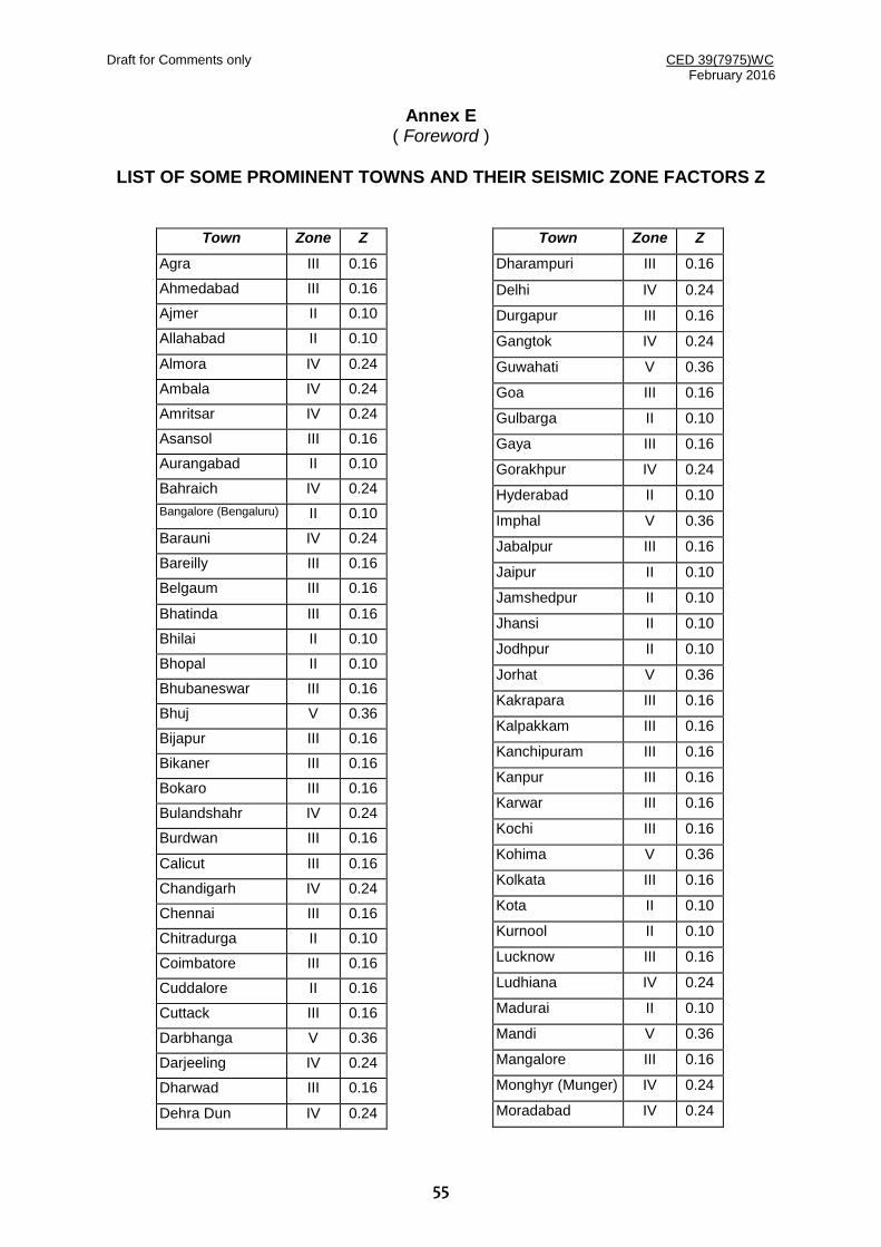
Draft for Comments only CED 39(7975)WC February 2016
55
Annex E ( Foreword )
LIST OF SOME PROMINENT TOWNS AND THEIR SEISMIC ZONE FACTORS Z
Town Zone Z
Agra III 0.16
Ahmedabad III 0.16
Ajmer II 0.10
Allahabad II 0.10
Almora IV 0.24
Ambala IV 0.24
Amritsar IV 0.24
Asansol III 0.16
Aurangabad II 0.10
Bahraich IV 0.24
Bangalore (Bengaluru) II 0.10
Barauni IV 0.24
Bareilly III 0.16
Belgaum III 0.16
Bhatinda III 0.16
Bhilai II 0.10
Bhopal II 0.10
Bhubaneswar III 0.16
Bhuj V 0.36
Bijapur III 0.16
Bikaner III 0.16
Bokaro III 0.16
Bulandshahr IV 0.24
Burdwan III 0.16
Calicut III 0.16
Chandigarh IV 0.24
Chennai III 0.16
Chitradurga II 0.10
Coimbatore III 0.16
Cuddalore II 0.16
Cuttack III 0.16
Darbhanga V 0.36
Darjeeling IV 0.24
Dharwad III 0.16
Dehra Dun IV 0.24
Town Zone Z
Dharampuri III 0.16
Delhi IV 0.24
Durgapur III 0.16
Gangtok IV 0.24
Guwahati V 0.36
Goa III 0.16
Gulbarga II 0.10
Gaya III 0.16
Gorakhpur IV 0.24
Hyderabad II 0.10
Imphal V 0.36
Jabalpur III 0.16
Jaipur II 0.10
Jamshedpur II 0.10
Jhansi II 0.10
Jodhpur II 0.10
Jorhat V 0.36
Kakrapara III 0.16
Kalpakkam III 0.16
Kanchipuram III 0.16
Kanpur III 0.16
Karwar III 0.16
Kochi III 0.16
Kohima V 0.36
Kolkata III 0.16
Kota II 0.10
Kurnool II 0.10
Lucknow III 0.16
Ludhiana IV 0.24
Madurai II 0.10
Mandi V 0.36
Mangalore III 0.16
Monghyr (Munger) IV 0.24
Moradabad IV 0.24

Draft for Comments only CED 39(7975)WC February 2016
56
Town Zone Z
Mumbai III 0.16
Mysore II 0.10
Nagpur II 0.10
Nagarjunasagar II 0.10
Nainital IV 0.24
Nasik III 0.16
Nellore III 0.16
Osmanabad III 0.16
Panjim III 0.16
Patiala III 0.16
Patna IV 0.24
Pilibhit IV 0.24
Pondicherry II 0.10
Pune III 0.16
Raipur II 0.10
Rajkot III 0.16
Ranchi II 0.10
Roorkee IV 0.24
Rourkela II 0.10
Sadiya V 0.36
Town Zone Z
Salem III 0.16
Shillong V 0.36
Shimla IV 0.24
Sironj II 0.10
Solapur III 0.16
Srinagar V 0.36
Surat III 0.16
Tarapur III 0.16
Tezpur V 0.36
Thane III 0.16
Thanjavur II 0.10
Thiruvananthapuram III 0.16
Tiruchirappalli II 0.10
Thiruvannamalai III 0.16
Udaipur II 0.10
Vadodara III 0.16
Varanasi III 0.16
Vellore III 0.16
Vijayawada III 0.16
Vishakhapatnam II 0.10
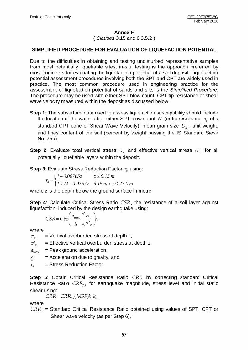
Draft for Comments only CED 39(7975)WC February 2016
57
Annex F ( Clauses 3.15 and 6.3.5.2 )
SIMPLIFIED PROCEDURE FOR EVALUATION OF LIQUEFACTION POTENTIAL
Due to the difficulties in obtaining and testing undisturbed representative samples from most potentially liquefiable sites, in-situ testing is the approach preferred by most engineers for evaluating the liquefaction potential of a soil deposit. Liquefaction potential assessment procedures involving both the SPT and CPT are widely used in practice. The most common procedure used in engineering practice for the assessment of liquefaction potential of sands and silts is the Simplified Procedure. The procedure may be used with either SPT blow count, CPT tip resistance or shear wave velocity measured within the deposit as discussed below: Step 1: The subsurface data used to assess liquefaction susceptibility should include
the location of the water table, either SPT blow count N (or tip resistance cq of a
standard CPT cone or Shear Wave Velocity), mean grain size 50D , unit weight,
and fines content of the soil (percent by weight passing the IS Standard Sieve No. 75μ).
Step 2: Evaluate total vertical stress v and effective vertical stress v' for all
potentially liquefiable layers within the deposit. Step 3: Evaluate Stress Reduction Factor dr using:
m023zm159z026701741
m159zz0076501rd . ...
..
where z is the depth below the ground surface in metre. Step 4: Calculate Critical Stress Ratio CSR, the resistance of a soil layer against
liquefaction, induced by the design earthquake using:
d
v
v rg
a650CSR
'. max
,
where
v = Vertical overburden stress at depth z,
v' = Effective vertical overburden stress at depth z,
maxa = Peak ground acceleration,
g = Acceleration due to gravity, and
dr = Stress Reduction Factor.
Step 5: Obtain Critical Resistance Ratio CRR by correcting standard Critical
Resistance Ratio 57CRR . for earthquake magnitude, stress level and initial static
shear using: kkMSFCRRCRR 57. ,
where
57CRR . = Standard Critical Resistance Ratio obtained using values of SPT, CPT or
Shear wave velocity (as per Step 6),
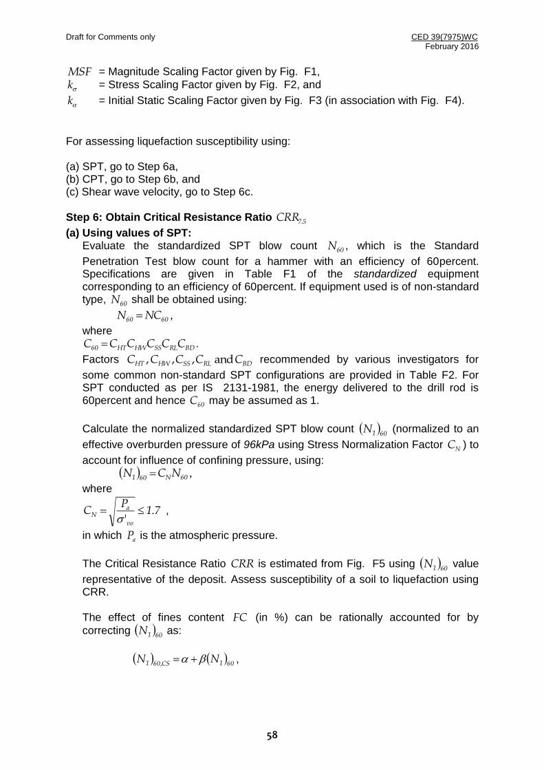
Draft for Comments only CED 39(7975)WC February 2016
58
MSF = Magnitude Scaling Factor given by Fig. F1,
k = Stress Scaling Factor given by Fig. F2, and
k = Initial Static Scaling Factor given by Fig. F3 (in association with Fig. F4).
For assessing liquefaction susceptibility using: (a) SPT, go to Step 6a, (b) CPT, go to Step 6b, and (c) Shear wave velocity, go to Step 6c. Step 6: Obtain Critical Resistance Ratio 57CRR .
(a) Using values of SPT: Evaluate the standardized SPT blow count 60N , which is the Standard
Penetration Test blow count for a hammer with an efficiency of 60percent. Specifications are given in Table F1 of the standardized equipment corresponding to an efficiency of 60percent. If equipment used is of non-standard type, 60N shall be obtained using:
6060 NCN ,
where
BDRLSSHWHT60 CCCCCC .
Factors BDRLSSHWHT CCCCC and ,, , recommended by various investigators for
some common non-standard SPT configurations are provided in Table F2. For SPT conducted as per IS 2131-1981, the energy delivered to the drill rod is 60percent and hence 60C may be assumed as 1.
Calculate the normalized standardized SPT blow count 601N (normalized to an
effective overburden pressure of 96kPa using Stress Normalization Factor NC ) to
account for influence of confining pressure, using: 60N601 NCN ,
where
71P
Cvo
aN .
'
,
in which aP is the atmospheric pressure.
The Critical Resistance Ratio CRR is estimated from Fig. F5 using 601N value
representative of the deposit. Assess susceptibility of a soil to liquefaction using CRR.
The effect of fines content FC (in %) can be rationally accounted for by
correcting 601N as:
601CS601 NN , ,

Draft for Comments only CED 39(7975)WC February 2016
59
where
% for..
%% for.
% for
..
35FC2150
35FC51000
FC990e
5FC10
51FC
190761
2
.
Fig. F5 shall be used to estimate CRR, where CS601N , shall be used instead of
601N and only SPT clean sand based curve shall be used irrespective of fines
contents. (b) Using values of CPT:
Calculate normalized Cone Tip Resistance CSN1Cq using:
N1CCCSN1C qkq ,
where
641I8817I7533I6321I5815I4030
641I01
k
c2c
2c
3c
4c
c
c
. for.....
. for.
sticsCharacteriGrain for account to factor Correction
, and
a
cQN1CP
qCq ,
in which n
vo
aQ
PC
'
cq = Measured cone tip resistance corrected for thin layers,
Clay For
Sand For.
1
50n ,
22c F221Q473I log.log. ,
n
v
a
a
vc P
P
,
vc
s
q
f100F
, and
sf = Measured sleeve friction.
Assess susceptibility of a soil to liquefaction using Fig. F6. Although soils with
62Ic . are deemed non-liquefiable, such deposits may soften and deform during
earthquakes. General guidance is not available to deal with such possibilities. Softening and deformability of deposits with 62Ic . should thus be treated on a
material specific basis.

Draft for Comments only CED 39(7975)WC February 2016
60
(c) Using Shear Wave Velocity: Calculate normalized Shear Wave Velocity 1sV for clean sands using:
s
250
v
a1s V
PV
.
.
Assess liquefaction susceptibility of clean sands using Fig. F7. Step 7: Calculate the Factor of Safety FS against initial liquefaction using:
CSR
CRRFS ,
where CSR is as estimated in Step 5 and CRR in Step 6. When the design ground
motion is conservative, earthquake-related permanent ground deformation is generally small, if 21FS . .
Table F1 Recommended Standardized SPT Equipment
Element Standard Specification
Sampler Standard split-spoon sampler with: Outside diameter OD = 51 mm, and Inside Diameter ID = 35 mm (constant, that is, no room for liners in the barrel)
Drill Rods A or AW type for depths less than 15.2 m; N or NW type for greater depths
Hammer Standard (safety) hammer with (a) weight = 63.5 kg; and (b) drop height = 762 mm (delivers 60 of theoretical free fall energy)
Rope Two wraps of rope around the pulley
Borehole 100-130mm diameter rotary borehole with bentonite mud for borehole stability (hollow stem augers where SPT is taken through the stem)
Drill Bit Upward deflection of drilling mud (tricone or baffled drag bit)
Blow Count Rate 30 to 40 blows per minute
Penetration Resistant Count
Measured over range of 150mm–460 mm of penetration into the ground

Draft for Comments only CED 39(7975)WC February 2016
61
Table F2 Correction Factors for Non-Standard SPT Procedures and Equipment
Correction for Correction Factor
Nonstandard Hammer Type
/auto tripwith DH for.
pulley and ropewith DH for.
331
750CHT
and ER = 80, where DH= doughnut hammer, and ER = energy ratio.
Nonstandard Hammer Weight or Height of fall
38748
HWCHW
,
where H = height of fall (mm), and W = hammer weight (kg)
Nonstandard Sampler Setup (standard samples with room for liners, but used without liners
sand dense for.
sand loose for.
21
11CSS
Nonstandard Sampler Setup (standard samples with room for liners, but liners are used)
sand dense for.
sand loose for.
80
90CSS
Short Rod Length CRL =0.75 for rod length 0-3 m
Nonstandard Borehole Diameter
mm 200 of Diameter Hole Bore for.
mm 150 of Diameter Hole Bore for.
mm 115-65 of Diamter Hole Bore for.
151
051
001
CBD
Notes N= Uncorrected SPT Blow Count
BDRLSSHWHT60 CCCCCC
6060 NCN
CN = Correction factor for overburden pressure = NCCN 60N601

Draft for Comments only CED 39(7975)WC February 2016
62
FIG. F1 MAGNITUDE SCALING FACTORMSF
FIG. F2 STRESS SCALING FACTOR k
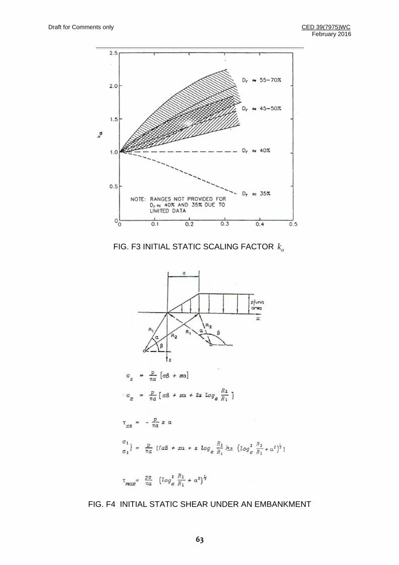
Draft for Comments only CED 39(7975)WC February 2016
63
FIG. F3 INITIAL STATIC SCALING FACTOR k
FIG. F4 INITIAL STATIC SHEAR UNDER AN EMBANKMENT
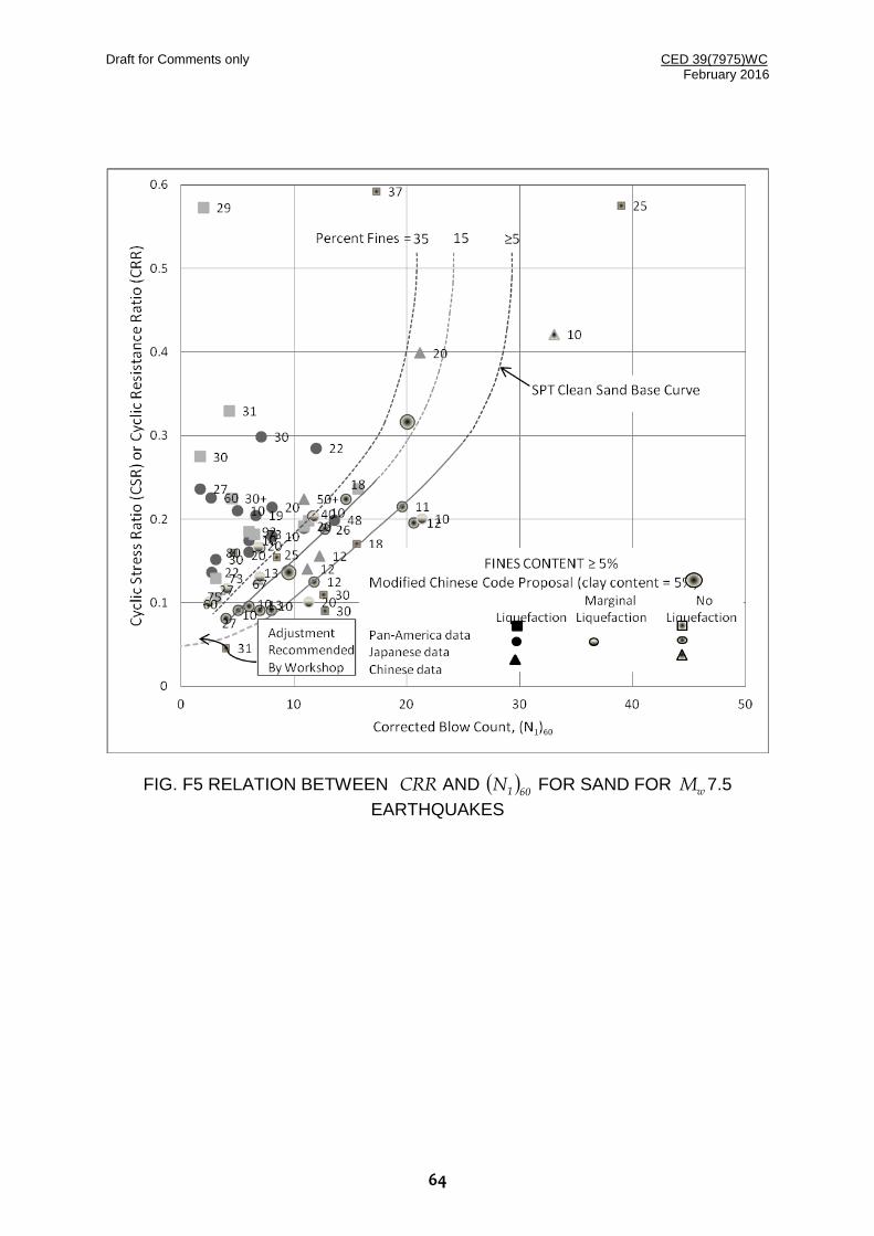
Draft for Comments only CED 39(7975)WC February 2016
64
FIG. F5 RELATION BETWEEN CRR AND 601N FOR SAND FOR wM 7.5
EARTHQUAKES

Draft for Comments only CED 39(7975)WC February 2016
65
FIG. F6 RELATION BETWEEN CRR AND csN1cq FOR wM 7.5 EARTHQUAKES
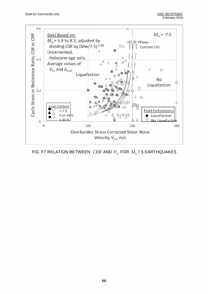
Draft for Comments only CED 39(7975)WC February 2016
66
FIG. F7 RELATION BETWEEN CRR AND 1sV FOR wM 7.5 EARTHQUAKES
Draft for Comments only CED 39(7975)WC February 2016
67
ANNEX G ( Foreword )
PERFORMANCE-BASED DESIGN (For Information Only)
G-1 DEFINITIONS
The following definitions are applicable for this informative Annex.
G-1.1 Performance-Based Seismic Design
Framework for seismic design of structures to ensure the targeted performance under specified hazard level(s). The performance is indicator of the damage expected in various structural and non-structural components and is usually quantified in terms of plastic deformation in different structural components, drift (maximum inter-storey drift in case of buildings), and acceleration at the level of connection of the non-structural component. In this methodology, the inelastic response of considered structure under specified hazard level is explicitly estimated.
G-1.2 Force Based Design
The earthquake resistant design methodology, followed by most of the current design codes, worldwide, in which the different components of the structure are designed to have specified minimum strength. It is accompanied by prescribed detailing of structural configuration, reinforcement and connections, and specified hierarchy of strength in different components and modes of failure. The inelastic energy dissipation by the structure during earthquake is accounted for approximately by specifying ‘Response Reduction Factors’ for different classes of structures.
G-1.3 Displacement Based Design
In this approach the structure is designed to achieve a specified deformation state under the considered hazard level. Contrary to force based design, in this approach the members are proportioned for local deformation demand and not the strength.
G-1.4 Performance Objective
A desired level of seismic performance, expressed in terms of acceptable structural and non-structural damage for a specified level of seismic hazard (for example, DBE, MCE).
G-1.5 Performance Level
A limiting damage state or condition described by the physical damage to different structural and non-structural components, threat to life safety of occupants/users, and post-earthquake serviceability of the structure.
G-1.6 ‘Operational’ Building Performance Level
Buildings meeting this target Building Performance Level are expected to sustain minimal or no damage to their structural and non-structural components. The building is suitable for its normal occupancy and use, although possibly in a slightly impaired mode, with power, water, and other required utilities provided from emergency sources, and possibly with some nonessential systems not functioning.
Draft for Comments only CED 39(7975)WC February 2016
68
Buildings meeting this target Building Performance Level pose an extremely low Life Safety risk.
G-1.7 ‘Immediate Occupancy’ Structural Performance Level
The post-earthquake damage state in which only very limited structural damage has occurred. The basic vertical- and lateral-force-resisting systems of the building retain almost all of their pre-earthquake strength and stiffness. The risk of life-threatening injury as a result of structural damage is very low, and although some minor structural repairs might be appropriate, these repairs would generally not be required before re-occupancy.
G-1.8 ‘Life Safety’ Structural Performance Level
The post-earthquake damage state in which a structure has damaged components but retains a margin against the onset of partial or total collapse. The damage has not resulted in large falling debris hazards, either inside or outside the building. Injuries might occur during the earthquake; however, the overall risk of life-threatening injury as a result of structural damage is expected to be low.
G-1.9 ‘Collapse Prevention’ Structural Performance Level
The post-earthquake damage state in which a structure has components damaged to an extent that it has no margin against collapse but it continues to support gravity loads. The building is on the verge of partial or total collapse. Substantial damage to the structure has occurred, potentially including significant degradation in the stiffness and strength of the lateral-force-resisting system and large permanent lateral deformation of the structure.
G-2 Performance Based Design procedures can be used for design of structural systems not covered by this code and for design of structures for a better seismic performance objective than that intended in this code. Structures, including structural and non-structural components and their connections shall be demonstrated using appropriate analysis or experimental testing or by a combination of analysis and structural testing to provide a seismic performance equivalent or better than that intended in this code. Due consideration shall be given to the uncertainties associated with demand (loading) and capacity (resistance).
Minimum performance objective for buildings with Importance Factor, I=1.0 shall be ‘Collapse Prevention’ for the Maximum Considered Earthquake (MCE). For Important buildings (I=1.5), the minimum performance objective shall be ‘Immediate Occupancy’ for the ‘Design Basis Earthquake (DBE)’ and ‘Life Safety’ for the MCE. For hospital and other lifeline buildings, the non-structural components shall be demonstrated to have ‘Operational’ performance level for DBE. Enhanced performance objectives can be formulated in consultation with the owner, occupants and authority having jurisdiction. In no case, the prescriptive design criteria for regularity of structural configuration, and requirements for stiffness, strength and ductility laid down in this code, shall be diluted.
Nonlinear static or nonlinear dynamic analysis procedure, with appropriate assumptions regarding stiffness, damping, strength and hysteretic behaviour can be used. The assumptions shall be based on approved test data and/or referenced standards. Use of nonlinear static procedure shall be permitted for buildings having

Draft for Comments only CED 39(7975)WC February 2016
69
regular configuration and negligible higher mode effects. For buildings having configurational irregularities or significant higher mode effects, nonlinear dynamic procedure (Nonlinear Time History Analysis) shall be required. Appropriate acceptance criteria in terms of plastic deformations in members, interstorey drift, and strain limits in different materials, for different performance levels shall be used based on approved test data and/or referenced standards. Till such standards are developed for Indian conditions, the analysis procedures, modelling assumptions and acceptance criteria of ASCE 41 can be used.
Independent peer review is an essential part of the performance-based design framework. The reviewer must have appropriate expertise and understanding of the structural system, loading, analysis method and testing procedure used.
G-3 COMMENTARY
A number of new structural systems and materials are gradually becoming popular in the Indian construction industry. Further, the intended performance objective of ‘No Collapse’ in case of a major earthquake may not be acceptable for some owners and users of ordinary buildings and for important buildings. Therefore, it is important to allow for alternative design methods to promote innovation and enhanced performance objectives. Performance-based design is a promising tool, gaining popularity world-over, and it is timely that it is adopted in Indian code. However, at the same time, it should be safeguarded against misuse and diluting the requirements of the current code of practice. The prescriptive guidelines of the existing codes in terms of selection of structural configuration, minimum design force levels, and detailing for ductility enhancement are time tested and cannot be compromised with in any case. It is to be noted that ASCE 41 (and other related documents) have been developed for seismic performance evaluation of existing buildings. The codes for new construction are intended to regulate the design and construction of new structures such that to encourage or require features for good seismic performance. Many existing buildings are designed and constructed without such features and therefore, ASCE 41 caters to much wider range of structures, which cannot be encouraged for new construction.
Performance-based design is primarily a displacement-based design methodology, which requires realistic (or conservative) estimates of displacement. This necessitates the use of reasonable effective stiffness estimates for cracked sections in case of RC members. In case of the current force-based design approach of IS 1893, an overestimation of stiffness may be conservative for evaluating the design base shear, but in case of displacement-based approach an overestimation of stiffness will be non-conservative. Therefore, proper modelling of stiffness is a crucial step in performance-based design. Effective stiffness of RC members depends on a number of factors, including level of axial force in the member, reinforcement ratio, and grades of concrete and steel. In absence of more reliable test results for Indian conditions, the guidelines of ASCE 41 can be used for this purpose.
Another important deviation in displacement-based design approach, as compared with the conventional force-based design approach, is use of ‘Expected’ strength of components in place of the Characteristic (or ‘Nominal’, or ‘Specified’ or ‘Lower-bound’) strength. The relationship between expected and characteristic strength, depends on the manufacturing process and quality control. It is to be estimated

Draft for Comments only CED 39(7975)WC February 2016
70
considering the variance of test results. There is need to conduct a large number of tests on different materials being used in India in different regions and under different conditions of manufacturing. It is to be noted that different standards/documents have significant variation in this regard, and the values specified in a different national standard, e.g. ASCE 41 are to be used with caution.
Significant variation exists among different documents/standards available on Performance-/Displacement-Based design, regarding the definition and acceptance criteria for different performance levels. Similar uncertainty also exists about the modelling of inelastic (nonlinear cyclic) behaviour of different components. The structural designer should refer to more than one standard/document and use more than one performance acceptance criteria to take into account the uncertainty. The performance acceptance criteria should also be supported by test results, as far as possible. The relevant documents/standards in this regard are listed below:
ASCE 41-13, (2013), Seismic Evaluation and Retrofit of Existing Buildings, American Society of Civil Engineers, Reston, USA.
Dubai Municipality, (2013), Seismic Design Code for Dubai
Calvi G.M., and Sullivan, T.J., (2009), A Model Code for Displacement-Based Seismic Design of Structures, IUSS Press, Pavia, Italy.
Fib Bulletin 65, (2012), Model Code 2010, final draft, International Federation for Structural Concrete, Lusanne, Switzerland.
Priestley, M.J.N., Calvi, M., and Cowalsky, M.J., (2007), Displacement-Based Seismic Design of Structures, IUSS Press, Pavia, Italy.
PEER / ATC-72-1 (2010). Modelling and Acceptance Criteria for Seismic Design and Analysis of Tall Buildings, Applied Technology Council, Redwood City, California.

Draft for Comments only CED 39(7975)WC February 2016
71
ANNEX H ( Foreword )
DESIGN OF SLAB-COLUMN SYSTEMS (For Information Only)
H-1 DEFINITION
The following definitions are applicable for this informative Annex.
H-1.1 Slab-column Frame System
A building structural system also known as flat-slab or flat plate system, having RC slabs directly supported on columns, without beams. The system is known to have brittle punching shear failure around the slab-column connections and is not recommended to be used as primary lateral load resisting system in seismic regions.
H-1.2 Lateral Force Resisting System (LFRS)
A structural system having adequate stiffness, strength and ductility in lateral direction, which can be used as primary system to resist earthquake forces. The common LRFS include RC shear walls, RC/Steel moment resisting (rigid jointed) frames, and steel braced frames.
H-1.3 Gravity Shear Ratio (VR)
Fraction of the punching shear capacity consumed by gravity loads (Dead Load, Live Load and Snow load, if applicable). It is defined as the ratio of the two-way (punching) shear stress at critical section due to gravity loads, to the punching shear strength, calculated in accordance with Cl. 31.6 of IS 456.
H-2 The slab-column systems, commonly known as flat-slab or flat-plate systems cannot be used as lateral force resisting systems in seismic regions. However, these can be used as non-seismic load resisting systems along with other primary lateral force resisting systems (LFRS), such as shear walls or moment resisting frames. When used along with these LFRS, the compatibility of the slab-column system with the LFRS in lateral drift is crucial. Mere designing of the LFRS for the full design base shear is not adequate, and the slab-column system shall be demonstrated to retain its vertical load carrying capacity subjected to the resulting inter-storey drifts. This requires a performance (displacement) based design approach considering all potential failure modes including flexure, shear, shear-moment transfer and reinforcement development at any section. The analytical model shall consider effective stiffness of cracked sections of slab and other RC elements including shear walls, shall have explicit modelling of torsional stiffness of slab-column joint, and shall capture the potential for both slab yielding and connection failure due to punching. ASCE 41 and ACI 318 guidelines for modelling and acceptance criteria for slab-column building systems can be used, till detailed guidelines are provided in the relevant Indian codes.
The primary LFRS used in slab-column buildings shall be designed to provide adequate stiffness, strength and torsional rigidity to the building. In case of shear walls being used as the primary LFRS, the walls shall be provided symmetrically in both the directions and as far away from the center of the building as possible,

Draft for Comments only CED 39(7975)WC February 2016
72
preferably along the perimeter. The LFRS shall be proportioned to restrict the maximum interstorey drift DR (%) at DBE (R times the interstorey drift at design load), as
DR= 3.5 - 5×VR, for VR<0.6, and (1a)
DR= 0.5, for VR>0.6 (1b)
Where, VR is the gravity shear ratio (ratio of factored two-way shear force at the critical section due to dead and live loads to the shear strength of the slab-column joint).
Use of column or shear capitals, drop panels, and shear reinforcement in the form of stirrups and shear heads/ shear studs shall be permitted to enhance the shear strength of the slab-column joint. A response reduction factor of 4 shall be used for design of shear walls and shear walls shall be designed and detailed following the provisions of IS 13920. The columns shall also be detailed as per IS 13920. For ductile detailing of beam-column joints, the provisions of ACI 318 shall be followed.
In case of shear wall-flat slab buildings without masonry infills and up to 20 storeys tall, use of the following simplified procedure shall be permitted:
1. Modelling of shear wall-flat slab system, using equivalent frame approach, with cracked section stiffness, equivalent width of slab, and explicit modelling of joint torsional rigidity.
2. Analysis using multi-mode superposition method, considering adequate number of modes contributing more than 90% seismic mass or using time history analysis method. Use response reduction factor of 4 and scale the design base shear as per the requirements of Cl. 7.7.3.
3. Check for adequacy of torsional rigidity, according to the following conditions:
(i) The slenderness λ = Lmax/Lmin of the building in plan shall not be higher than 4, where, Lmax and Lmin are respectively the larger and smaller dimensions in plan of the building, measured in orthogonal directions.
(ii) At each level and for each direction of analysis x and y, the structural eccentricity eo and the torsional radius r shall be in accordance with the two conditions below, which are expressed for the direction of analysis y: eox ≤ 0.30 rx (2)
and
rx ≥ ls (3)
where, eox is the distance between the centre of stiffness and the centre of mass, measured along the x direction, which is normal to the direction of analysis considered;
rx is the square root of the ratio of the torsional stiffness to the lateral stiffness in the y direction (“torsional radius”); and
Draft for Comments only CED 39(7975)WC February 2016
73
ls is the radius of gyration of the floor mass in plan (square root of the ratio of the polar moment of inertia of the floor mass in plan with respect to the centre of mass of the floor to the floor mass).
4. Design slab, columns, and slab-column joints, using the provisions of IS 456, for different load combinations as per IS 1893.
5. Design of shear walls using the provisions of IS 1893. Detail the reinforcement in all the components according to IS 13920 provisions.
6. Check that R times the maximum inter-storey drift DR is less than the specified limit (Eqn. 1). If the interstorey drift is more than the limit, provide shear reinforcement in the slab as per ACI 318-15 guidelines or revise the design with increased size of shear walls and/or increased thickness of slab/shear capitals.
7. Detail the slab reinforcement as per guidelines of ACI 318, with continuity of at least 50% of the bottom bars in column strip and minimum 2 bars passing through the cage of the column reinforcement.
H-3 COMMENTARY
Flat slab buildings provide some advantages as compared to the conventional beam-column frame systems, such as use of relatively simple formwork and shorter storey heights and are becoming popular in Indian construction industry. However, these buildings are known for their poor seismic performance due to their flexibility and brittle punching shear failure. In absence of adequate design guidelines for seismic loads, these are being designed and constructed without due care. Therefore, it is important that detailed seismic design guidelines are provided in the code for these buildings.
Due to their shortcomings in terms of lack of stiffness and ductility, these buildings cannot be used as primary lateral load resisting system and another lateral force resisting system (LFRS) is required to support these buildings. The LFRS should have adequate strength, stiffness and inelastic energy dissipation capacity. RC shear walls are an ideal LFRS to be used in conjunction with flat slab buildings. However, it is to be noted that these buildings also suffer from lack of torsional rigidity and shear walls should be so configured and placed that the building as a whole has adequate torsional rigidity. The EC8 guidelines are the most elaborate in this context and can be used for this purpose.
In addition to strength, the shear walls should have adequate stiffness, so that the drift of the building is controlled to avoid a brittle punching shear failure. Experiments have shown that the drift at which brittle punching shear failure of flat slab buildings takes place, depends on the gravity shear ratio. ACI 318 provides a simple relationship between the maximum permitted interstorey drift and the gravity shear ratio. Further, the continuity of bottom reinforcement and its anchorage into column is crucial to ensure a nominal residual strength to avoid catastrophic failure. To control the interstorey drift within permissible limits a displacement based analysis using nonlinear modelling is necessary. However, the shear wall-flat slab buildings
Draft for Comments only CED 39(7975)WC February 2016
74
usually being long period structures, the equal displacement principle can be assumed to be valid and the inelastic drift can be approximated with the elastic drift.
Masonry infills are known to act as diagonal struts and completely alter the behaviour of frame (and flat slab) buildings. The main effect of these struts is exertion of high shear force on columns and beams in a frame buildings. In case of flat slab buildings, this strut action is expected to further aggravate the punching shear failure and lead to catastrophic collapse of slab, due to lack of residual vertical load carrying capacity. Therefore, use of masonry infills is to be avoided in case of flat slab buildings, until unless it is demonstrated to be safe using accepted testing and analytical procedures.
ANNEX I ( Foreword )
COMMITTEE COMPOSITION
Earthquake Engineering Sectional Committee, CED 39
WILL BE INCLUDED AFTER FINALIZATION
**********