ats 48 软起动-软停止单元 - gongkong
TRANSCRIPT
ATS 48软起动-软停止单元
用户手册
User's Manual

ATS 48
中
文
EN
GLIS
H
中文 2
英文 84
1
2
中
文
按照规定,对设备或机器的任何电气或机械部件进行操作之前,ATS 48 的控制 (CL1-CL2) 和电
源 (1/L1-3/L2-5/L3) 必须断开。
在运行过程中可以通过取消运行命令使电机停机。起动器保持通电。如果为了人员安全需要禁止突
然重起动,则此电气锁定系统是不够的 : 必须在动力电路上安装一个断路器。
本起动器装有安全设备,当出现故障时,可以停止起动器工作继而使电机停机。电机自身可以通过
机械锁定停机。另外,电压变化或电源故障也会导致停机。
如果导致停机的原因消失,则存在重新起动的可能,这将危及某些机器或设备的安全,特别是那些
必须符合安全规范的机器或设备。在这种情况下用户必须采取措施预防自动重起动的发生,特别是
在电机出现不合程序要求的停机时,要使用低速检测器切断起动器的电源。
本文档中介绍的产品和设备可能会因技术原因随时变更或修改。我们保留更改的权力。
起动器安装和设置必须符合国际和国内标准的要求。系统集成商有责任确保设备的合格性,必须遵
守欧盟范围内其他国家的 EMC 规范。
本文档中的技术规范必须遵守,以符合 EMC 条款的基本要求。
ATS 48 必须被视为一个组件,它不是一部已经能够符合欧洲规范的机器或设备 ( 机械规范和电
磁兼容性规范 )。最终的集成商有责任确保其符合相关的标准。
3
中
文
目录
起动器设置步骤 4
出厂配置 6
初步建议 7
技术规格 8
操作建议 9
起动器 - 电机组合 12
尺寸 18
安装建议 20
壁挂式或落地式安装的壳体 21
电源端子 22
控制端子 27
连线 /RUN-STOP 命令 28
应用接线图 29
热保护 39
显示组件及编程 43
远程操作盘选件 46
设定菜单 (Set) 47
保护菜单 (PrO) 52
高级设定菜单 (drC) 56
I/O 菜单 (IO) 60
第二电机参数菜单 (St2) 64
通讯菜单 (COP) 68
参数显示菜单 (SUP) 70
兼容性表 73
维护 74
故障、原因、处理方法 75
配置 / 设定值表 80
4
中
文
起动器设置步骤
1、 ATS 48 的交货
• 检查印在标签上的起动器型号与定单相对应的提货单上标注的型号是否一致。• 打开 ATS 48 的包装,确认在运输过程中没有发生损坏。
2、 根据 20 页和 21 页上的指导安装 ATS 48
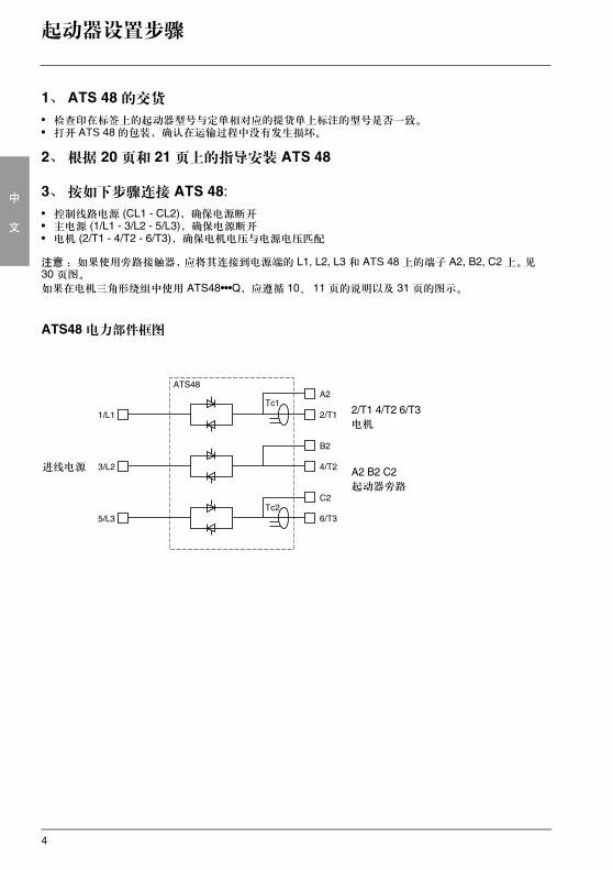
3、 按如下步骤连接 ATS 48:• 控制线路电源 (CL1 - CL2),确保电源断开• 主电源 (1/L1 - 3/L2 - 5/L3),确保电源断开• 电机 (2/T1 - 4/T2 - 6/T3),确保电机电压与电源电压匹配
注意 : 如果使用旁路接触器,应将其连接到电源端的 L1, L2, L3 和 ATS 48 上的端子 A2, B2, C2 上。见30 页图。
如果在电机三角形绕组中使用 ATS48•••Q,应遵循 10、 11 页的说明以及 31 页的图示。
ATS48 电力部件框图
进线电源
2/T1 4/T2 6/T3电机
A2 B2 C2起动器旁路
5
中
文
起动器设置步骤
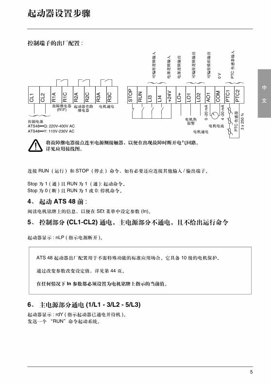
控制端子的出厂配置 :
连接 RUN ( 运行 ) 和 STOP ( 停止 ) 命令,如有必要还应连接其他输入 / 输出端子。
Stop 为 1 ( 通 ) 且 RUN 为 1 ( 通 ): 起动命令。
Stop 为 0 ( 断 ) 且 RUN 为 1 或 0: 停机命令。
4、 起动 ATS 48 前 :阅读电机铭牌上的信息,以便在 SEt 菜单中设定参数 (In)。
5、 控制部分 (CL1-CL2) 通电,主电源部分不通电,且不给出运行命令
起动器显示 : nLP ( 指示电源断开 )。
6、 主电源部分通电 (1/L1 - 3/L2 - 5/L3)起动器显示 : rdY ( 指示起动器已通电并待机 )。发送一个 “RUN”命令起动系统。
控制电源ATS48•••Q: 220V-400V ACATS48•••Y: 110V-230V AC
故障继电器 (R1F)
起动器旁路继电器
电机通电
可编程逻辑输入
电源逻辑输入
电源逻辑输出
可编程逻辑输出
可编程模拟输出
PT
C 传
感器输入
PT
C 传
感器
0 -2
0 m
A
4 -2
0 m
A
电机通电
电机热报警
电机电流
将故障继电器接点连至电源侧接触器,以便在出现故障时断开电气回路。
详见应用接线图。
3 x
250
¾
0 V
ATS 48 起动器出厂配置用于不需特殊功能的标准应用场合。它具备 10 级的电机保护。
通过改变参数改变设定值,详见第 44 页。
在任何情况下 In 参数都必须设置为电机铭牌上指示的当前值。
6
中
文
出厂配置
出厂设定值
ATS 48 出厂时已设定为普通的运行情况 :
• ATS 48 在电机电源上使用 ( 在电机绕组中未将其串入三角形绕组中 )
• 电机额定电流 In:- ATS 48•••Q: 为标准 400V 4 极电机预置- ATS 48•••Y: 为 NEC 电流、 460V 电机预置
• 限制电流 (ILt): 电机额定电流的 400%
• 加速斜坡 (ACC): 15 秒
• 起动力矩 (tq0): 额定力矩的 20%
• 停机 (StY): 自由停车 (-F-)
• 电机热保护 (tHP): 10 级保护曲线
• 显示 : rdY ( 起动器待机 ),有电源电压和控制电压,电机电流运行
• 逻辑输入 :- LI1: STOP ( 停机 )- LI2: RUN ( 运行 )- LI3: 强制自由停车 (LIA)- LI4: 强制本地模式 (LIL)
• 逻辑输出 :- LO1: 电机热报警 (tA1)- LO1: 电机已通电 (ml)
• 继电器输出 : - R1: 故障继电器 (rlI)- R2: 起动结束旁路继电器- R3: 电机已通电 (ml)
• 模拟输出 :- AO 电机电流 (Ocr, 0-20mA)
• 通讯参数 :
- 通过串口连接,起动器逻辑地址 (Add) 为 “0”- 传输速度 (tbr): 19200 比特每秒- 传输格式 (For): 8 位,无奇偶校验, 1 个停止位 (8nl)
如果上述值均符合实际应用,则起动器无须改变设定值即可使用。
7
中
文
初步建议
搬运和存放
在安装前为保护起动器,应带着包装进行搬运和存放。
安装搬运
ATS 48 系列有 6 种大小的设备,其重量和尺寸各不相同。
小型起动器可以去除包装,无需吊装设备即可安装。
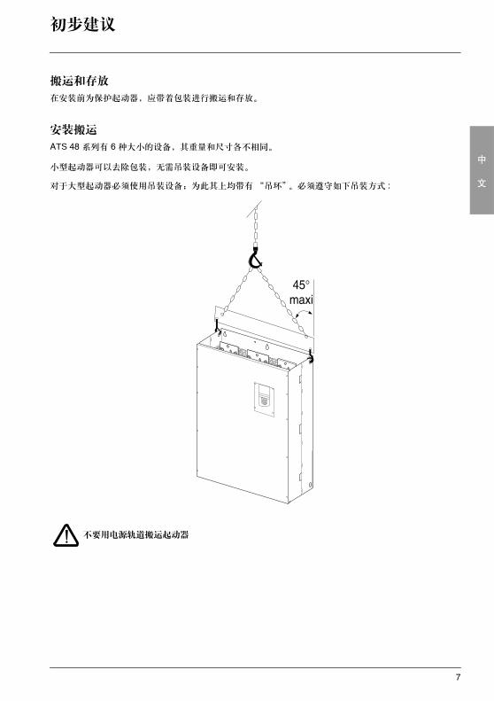
对于大型起动器必须使用吊装设备;为此其上均带有“吊环”。必须遵守如下吊装方式 :
不要用电源轨道搬运起动器
8
中
文
技术规格
环境
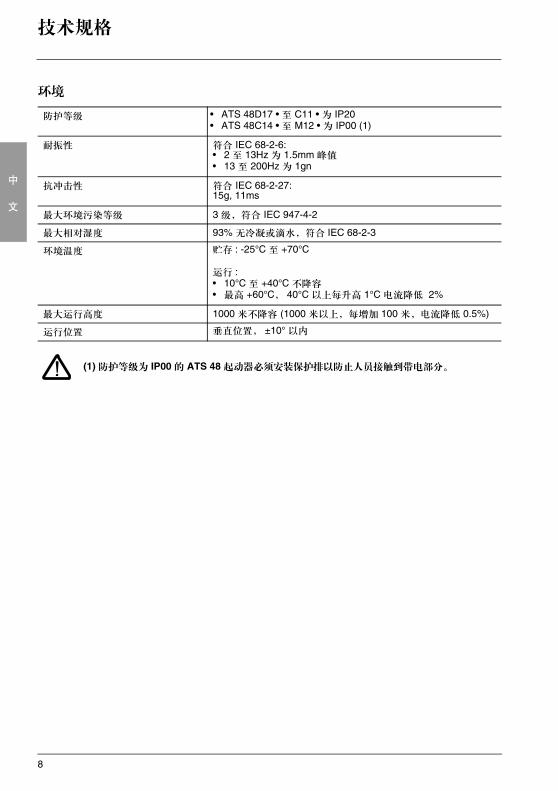
(1) 防护等级为 IP00 的 ATS 48 起动器必须安装保护排以防止人员接触到带电部分。
防护等级 • ATS 48D17 • 至 C11 • 为 IP20• ATS 48C14 • 至 M12 • 为 IP00 (1)
耐振性 符合 IEC 68-2-6:• 2 至 13Hz 为 1.5mm 峰值• 13 至 200Hz 为 1gn
抗冲击性 符合 IEC 68-2-27:15g, 11ms
最大环境污染等级 3 级,符合 IEC 947-4-2
最大相对湿度 93% 无冷凝或滴水,符合 IEC 68-2-3
环境温度 贮存 : -25°C 至 +70°C
运行 :• 10°C 至 +40°C 不降容• 最高 +60°C, 40°C 以上每升高 1°C 电流降低 2%
最大运行高度 1000 米不降容 (1000 米以上,每增加 100 米,电流降低 0.5%)
运行位置 垂直位置, ±10° 以内
9
中
文
操作建议
有效力矩
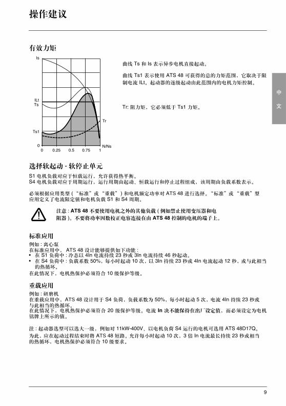
曲线 Ts 和 Is 表示异步电机直接起动。
曲线 Ts1 表示使用 ATS 48 可获得的总的力矩范围,它取决于限
制电流 ILt。起动器的逐级起动由此范围内的电机力矩控制。
Tr: 阻力矩,它必须低于 Ts1 力矩。
选择软起动 - 软停止单元
S1 电机负载对应于恒载运行,允许获得热平衡。S4 电机负载对应于周期运行,运行周期由起动、恒载运行和停止过程组成,该周期由负载系数表示。
必须根据应用类型 (“标准”或“重载” ) 和电机额定功率对 ATS 48 进行选择。“标准”或“重载”型应用定义了电流限定值和电机负载 S1 和 S4 周期。
注意 : ATS 48 不要使用电机之外的其他负载 ( 例如禁止使用变压器和电
阻器 )。不要将功率因数校正电容连接在由 ATS 48 控制的电机的端子上。
标准应用
例如 : 离心泵在标准应用中, ATS 48 设计能够提供如下功能 :• 在 S1 负荷中 : 冷态以 4In 电流持续 23 秒或 3In 电流持续 46 秒起动。• 在 S4 负荷中 : 负载系数 50%,每小时起动 10 次,以 3In 持续 23 秒或 4In 电流起动 12 秒,或与此相当
的热循环。
在此情况下,电机热保护必须符合 10 级保护等级。
重载应用
例如 : 研磨机在重载应用中,ATS 48 设计用于 S4 负荷,负载系数为 50%,每小时起动 5 次,电流 4In 持续 23 秒或与此相当的热循环。在此情况下,电机热保护必须符合 20 级保护等级。电流 In 决不能保持在出厂设定值,而必须设定为电机铭牌上所示的值。
注 : 起动器选型可以选大一级,例如对 11kW-400V、以电机负荷 S4 运行的电机可选用 ATS 48D17Q。
为此,应在起动过程结束时将 ATS 48 短路。允许每小时起动 10 次,3 倍 In 电流最长持续 23 秒或相当的热循环,电机热保护必须符合 10 级要求。
10
中
文
操作建议
ATS 48Q 系列 (230-400V) 与电机直接连接或连接到电机三角形绕组
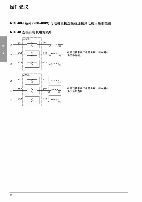
ATS 48 连接在电机电源线中
电机连接取决于电源电压,在本例中为星形连接。
电机连接取决于电源电压,在本例中为三角形连接。
11
中
文
操作建议
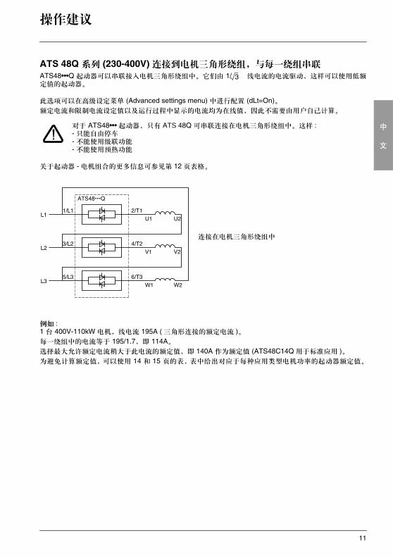
ATS 48Q 系列 (230-400V) 连接到电机三角形绕组,与每一绕组串联ATS48•••Q 起动器可以串联接入电机三角形绕组中。它们由 1/ 线电流的电流驱动,这样可以使用低额定值的起动器。
此选项可以在高级设定菜单 (Advanced settings menu) 中进行配置 (dLt=On)。额定电流和限制电流设定值以及运行过程中显示的电流均为在线值,因此不需要由用户自己计算。
对于 ATS48••• 起动器,只有 ATS 48Q 可串联连接在电机三角形绕组中。这样 :- 只能自由停车- 不能使用级联功能- 不能使用预热功能
关于起动器 - 电机组合的更多信息可参见第 12 页表格。
例如 :1 台 400V-110kW 电机,线电流 195A ( 三角形连接的额定电流 )。每一绕组中的电流等于 195/1.7,即 114A。选择最大允许额定电流稍大于此电流的额定值,即 140A 作为额定值 (ATS48C14Q 用于标准应用 )。为避免计算额定值,可以使用 14 和 15 页的表,表中给出对应于每种应用类型电机功率的起动器额定值。
连接在电机三角形绕组中
3
12
中
文
起动器 - 电机组合
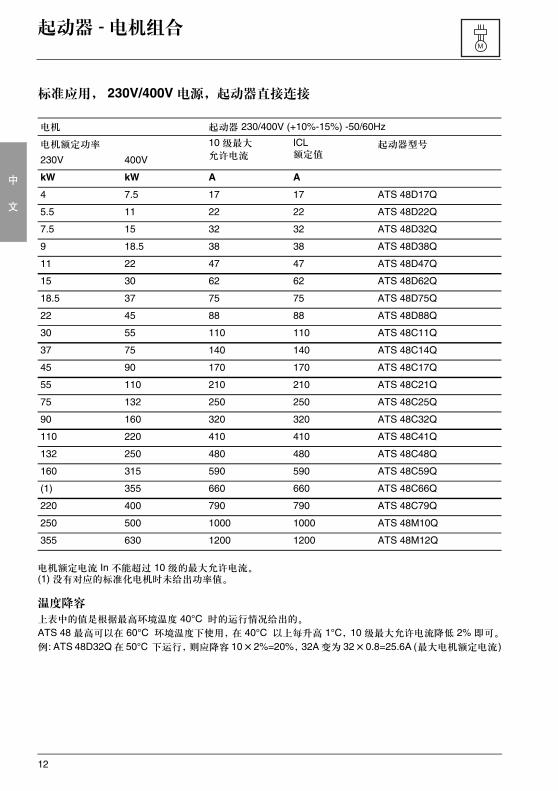
标准应用, 230V/400V 电源,起动器直接连接
电机额定电流 In 不能超过 10 级的最大允许电流。(1) 没有对应的标准化电机时未给出功率值。
温度降容
上表中的值是根据最高环境温度 40°C 时的运行情况给出的。
ATS 48 最高可以在 60°C 环境温度下使用,在 40°C 以上每升高 1°C,10 级最大允许电流降低 2% 即可。
例: ATS 48D32Q 在 50°C 下运行,则应降容 10×2%=20%,32A 变为 32×0.8=25.6A (最大电机额定电流)
电机 起动器 230/400V (+10%-15%) -50/60Hz
电机额定功率 10 级最大
允许电流
ICL额定值
起动器型号
230V 400V
kW kW A A
4 7.5 17 17 ATS 48D17Q
5.5 11 22 22 ATS 48D22Q
7.5 15 32 32 ATS 48D32Q
9 18.5 38 38 ATS 48D38Q
11 22 47 47 ATS 48D47Q
15 30 62 62 ATS 48D62Q
18.5 37 75 75 ATS 48D75Q
22 45 88 88 ATS 48D88Q
30 55 110 110 ATS 48C11Q
37 75 140 140 ATS 48C14Q
45 90 170 170 ATS 48C17Q
55 110 210 210 ATS 48C21Q
75 132 250 250 ATS 48C25Q
90 160 320 320 ATS 48C32Q
110 220 410 410 ATS 48C41Q
132 250 480 480 ATS 48C48Q
160 315 590 590 ATS 48C59Q
(1) 355 660 660 ATS 48C66Q
220 400 790 790 ATS 48C79Q
250 500 1000 1000 ATS 48M10Q
355 630 1200 1200 ATS 48M12Q
13
中
文
起动器 - 电机组合
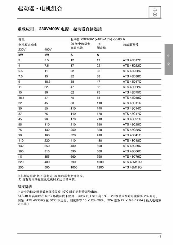
重载应用, 230V/400V 电源,起动器直接连接
电机额定电流 In 不能超过 20 级的最大允许电流。(1) 没有对应的标准化电机时未给出功率值。
温度降容
上表中的值是根据最高环境温度 40°C 时的运行情况给出的。
ATS 48 最高可以在 60°C 环境温度下使用, 40°C 以上每升高 1°C, 20 级最大允许电流降低 2% 即可。
例如 : ATS 48D32Q 在 50°C 下运行,则应降容 10 × 2%=20%, 22A 变为 22 × 0.8=17.6A ( 最大电机额定电流 )
电机 起动器 230/400V (+10%-15%) -50/60Hz
电机额定功率 20 级中的最大
允许电流ICL额定值
起动器型号
230V 400V
kW kW A A
3 5.5 12 17 ATS 48D17Q
4 7.5 17 22 ATS 48D22Q
5.5 11 22 32 ATS 48D32Q
7.5 15 32 38 ATS 48D38Q
9 18.5 38 47 ATS 48D47Q
11 22 47 62 ATS 48D62Q
15 30 62 75 ATS 48D75Q
18.5 37 75 88 ATS 48D88Q
22 45 88 110 ATS 48C11Q
30 55 110 140 ATS 48C14Q
37 75 140 170 ATS 48C17Q
45 90 170 210 ATS 48C21Q
55 110 210 250 ATS 48C25Q
75 132 250 320 ATS 48C32Q
90 160 320 410 ATS 48C41Q
110 220 410 480 ATS 48C48Q
132 250 480 590 ATS 48C59Q
160 315 590 660 ATS 48C66Q
(1) 355 660 790 ATS 48C79Q
220 400 790 1000 ATS 48M10Q
250 500 1000 1200 ATS 48M12Q
14
中
文
起动器 - 电机组合
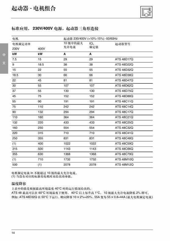
标准应用, 230V/400V 电源,起动器三角形连接
电机额定电流 In 不能超过 10 级的最大允许电流。(1) 当没有对应的标准化电机时未给出功率值。
温度降容
上表中的值是根据最高环境温度 40°C 时的运行情况给出的。
ATS 48 最高可以在 60°C 环境温度下使用, 40°C 以上每升高 1°C, 10 级最大允许电流降低 2% 即可。
例如: ATS 48D32Q 在 50°C 下运行,则应降容 10×2%=20%,55A 变为 55×0.8=44A (最大电机额定电流)
电机 起动器 230/400V (+10%-15%) -50/60Hz
电机额定功率 10 级中的最大
允许电流ICL额定值
起动器型号
230V 400V
kW kW A A
7.5 15 29 29 ATS 48D17Q
9 18.5 38 38 ATS 48D22Q
15 22 55 55 ATS 48D32Q
18.5 30 66 66 ATS 48D38Q
22 45 81 81 ATS 48D47Q
30 55 107 107 ATS 48D62Q
37 55 130 130 ATS 48D75Q
45 75 152 152 ATS 48D88Q
55 90 191 191 ATS 48C11Q
75 110 242 242 ATS 48C14Q
90 132 294 294 ATS 48C17Q
110 160 364 364 ATS 48C21Q
132 220 433 433 ATS 48C25Q
160 250 554 554 ATS 48C32Q
220 315 710 710 ATS 48C41Q
250 355 831 831 ATS 48C48Q
(1) 400 1022 1022 ATS 48C59Q
315 500 1143 1143 ATS 48C66Q
355 630 1368 1368 ATS 48C79Q
(1) 710 1732 1732 ATS 48M10Q
500 (1) 2078 2078 ATS 48M12Q
15
中
文
起动器 - 电机组合
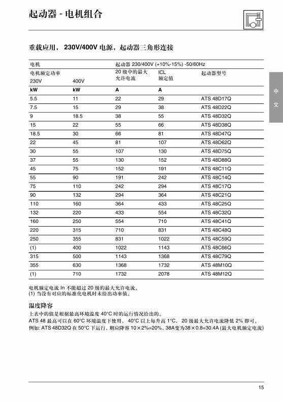
重载应用, 230V/400V 电源,起动器三角形连接
电机额定电流 In 不能超过 20 级的最大允许电流。(1) 当没有对应的标准化电机时未给出功率值。
温度降容
上表中的值是根据最高环境温度 40°C 时的运行情况给出的。
ATS 48 最高可以在 60°C 环境温度下使用, 40°C 以上每升高 1°C, 20 级最大允许电流降低 2% 即可。
例如: ATS 48D32Q 在 50°C 下运行,则应降容 10×2%=20%,38A变为38×0.8=30.4A (最大电机额定电流)
电机 起动器 230/400V (+10%-15%) -50/60Hz
电机额定功率 20 级中的最大
允许电流ICL额定值
起动器型号
230V 400V
kW kW A A
5.5 11 22 29 ATS 48D17Q
7.5 15 29 38 ATS 48D22Q
9 18.5 38 55 ATS 48D32Q
15 22 55 66 ATS 48D38Q
18.5 30 66 81 ATS 48D47Q
22 45 81 107 ATS 48D62Q
30 55 107 130 ATS 48D75Q
37 55 130 152 ATS 48D88Q
45 75 152 191 ATS 48C11Q
55 90 191 242 ATS 48C14Q
75 110 242 294 ATS 48C17Q
90 132 294 364 ATS 48C21Q
110 160 364 433 ATS 48C25Q
132 220 433 554 ATS 48C32Q
160 250 554 710 ATS 48C41Q
220 315 710 831 ATS 48C48Q
250 355 831 1022 ATS 48C59Q
(1) 400 1022 1143 ATS 48C66Q
315 500 1143 1368 ATS 48C79Q
355 630 1368 1732 ATS 48M10Q
(1) 710 1732 2078 ATS 48M12Q
16
中
文
起动器 - 电机组合
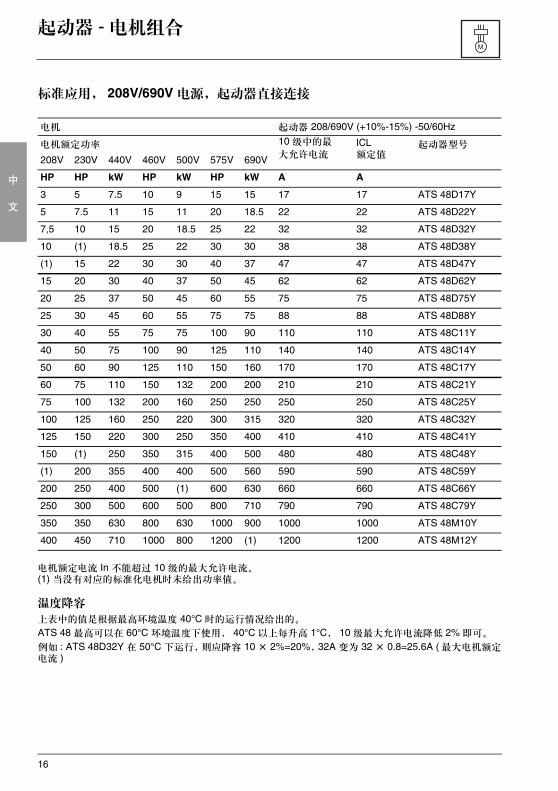
标准应用, 208V/690V 电源,起动器直接连接
电机额定电流 In 不能超过 10 级的最大允许电流。(1) 当没有对应的标准化电机时未给出功率值。
温度降容
上表中的值是根据最高环境温度 40°C 时的运行情况给出的。
ATS 48 最高可以在 60°C 环境温度下使用, 40°C 以上每升高 1°C, 10 级最大允许电流降低 2% 即可。
例如 : ATS 48D32Y 在 50°C 下运行,则应降容 10 × 2%=20%,32A 变为 32 × 0.8=25.6A ( 最大电机额定电流 )
电机 起动器 208/690V (+10%-15%) -50/60Hz
电机额定功率 10 级中的最
大允许电流ICL额定值
起动器型号
208V 230V 440V 460V 500V 575V 690V
HP HP kW HP kW HP kW A A
3 5 7.5 10 9 15 15 17 17 ATS 48D17Y
5 7.5 11 15 11 20 18.5 22 22 ATS 48D22Y
7,5 10 15 20 18.5 25 22 32 32 ATS 48D32Y
10 (1) 18.5 25 22 30 30 38 38 ATS 48D38Y
(1) 15 22 30 30 40 37 47 47 ATS 48D47Y
15 20 30 40 37 50 45 62 62 ATS 48D62Y
20 25 37 50 45 60 55 75 75 ATS 48D75Y
25 30 45 60 55 75 75 88 88 ATS 48D88Y
30 40 55 75 75 100 90 110 110 ATS 48C11Y
40 50 75 100 90 125 110 140 140 ATS 48C14Y
50 60 90 125 110 150 160 170 170 ATS 48C17Y
60 75 110 150 132 200 200 210 210 ATS 48C21Y
75 100 132 200 160 250 250 250 250 ATS 48C25Y
100 125 160 250 220 300 315 320 320 ATS 48C32Y
125 150 220 300 250 350 400 410 410 ATS 48C41Y
150 (1) 250 350 315 400 500 480 480 ATS 48C48Y
(1) 200 355 400 400 500 560 590 590 ATS 48C59Y
200 250 400 500 (1) 600 630 660 660 ATS 48C66Y
250 300 500 600 500 800 710 790 790 ATS 48C79Y
350 350 630 800 630 1000 900 1000 1000 ATS 48M10Y
400 450 710 1000 800 1200 (1) 1200 1200 ATS 48M12Y
17
中
文
起动器 - 电机组合
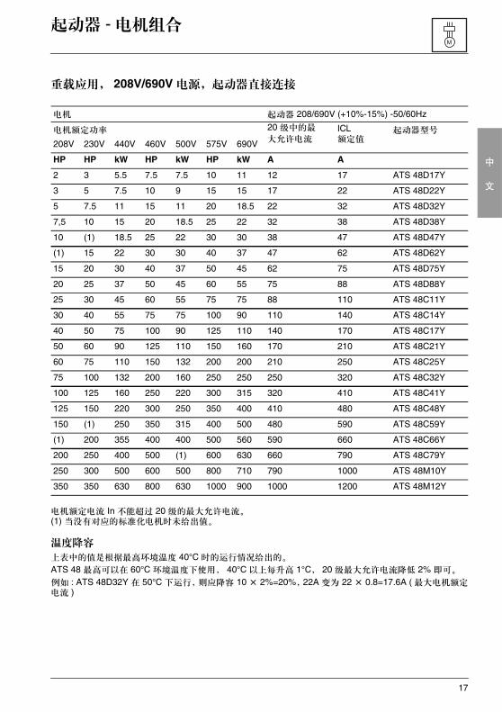
重载应用, 208V/690V 电源,起动器直接连接
电机额定电流 In 不能超过 20 级的最大允许电流。(1) 当没有对应的标准化电机时未给出值。
温度降容
上表中的值是根据最高环境温度 40°C 时的运行情况给出的。
ATS 48 最高可以在 60°C 环境温度下使用, 40°C 以上每升高 1°C, 20 级最大允许电流降低 2% 即可。
例如 : ATS 48D32Y 在 50°C 下运行,则应降容 10 × 2%=20%,22A 变为 22 × 0.8=17.6A ( 最大电机额定电流 )
电机 起动器 208/690V (+10%-15%) -50/60Hz
电机额定功率 20 级中的最
大允许电流ICL额定值
起动器型号
208V 230V 440V 460V 500V 575V 690V
HP HP kW HP kW HP kW A A
2 3 5.5 7.5 7.5 10 11 12 17 ATS 48D17Y
3 5 7.5 10 9 15 15 17 22 ATS 48D22Y
5 7.5 11 15 11 20 18.5 22 32 ATS 48D32Y
7,5 10 15 20 18.5 25 22 32 38 ATS 48D38Y
10 (1) 18.5 25 22 30 30 38 47 ATS 48D47Y
(1) 15 22 30 30 40 37 47 62 ATS 48D62Y
15 20 30 40 37 50 45 62 75 ATS 48D75Y
20 25 37 50 45 60 55 75 88 ATS 48D88Y
25 30 45 60 55 75 75 88 110 ATS 48C11Y
30 40 55 75 75 100 90 110 140 ATS 48C14Y
40 50 75 100 90 125 110 140 170 ATS 48C17Y
50 60 90 125 110 150 160 170 210 ATS 48C21Y
60 75 110 150 132 200 200 210 250 ATS 48C25Y
75 100 132 200 160 250 250 250 320 ATS 48C32Y
100 125 160 250 220 300 315 320 410 ATS 48C41Y
125 150 220 300 250 350 400 410 480 ATS 48C48Y
150 (1) 250 350 315 400 500 480 590 ATS 48C59Y
(1) 200 355 400 400 500 560 590 660 ATS 48C66Y
200 250 400 500 (1) 600 630 660 790 ATS 48C79Y
250 300 500 600 500 800 710 790 1000 ATS 48M10Y
350 350 630 800 630 1000 900 1000 1200 ATS 48M12Y
18
中
文
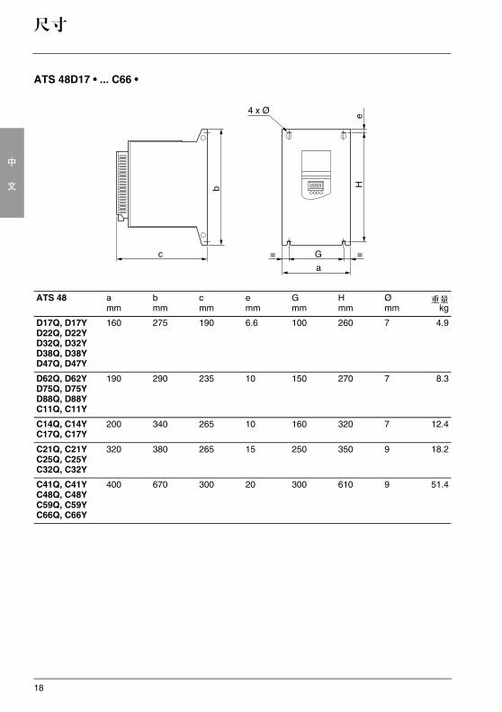
尺寸
ATS 48D17 • ... C66 •
ATS 48 amm
b mm
c mm
emm
G mm
H mm
Ømm
重量kg
D17Q, D17YD22Q, D22YD32Q, D32YD38Q, D38YD47Q, D47Y
160 275 190 6.6 100 260 7 4.9
D62Q, D62YD75Q, D75YD88Q, D88YC11Q, C11Y
190 290 235 10 150 270 7 8.3
C14Q, C14YC17Q, C17Y
200 340 265 10 160 320 7 12.4
C21Q, C21YC25Q, C25YC32Q, C32Y
320 380 265 15 250 350 9 18.2
C41Q, C41YC48Q, C48YC59Q, C59YC66Q, C66Y
400 670 300 20 300 610 9 51.4
19
中
文
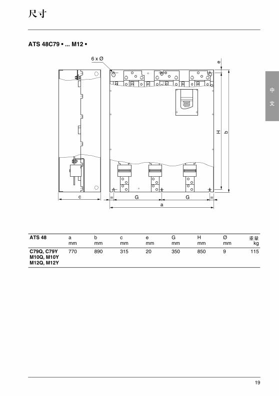
尺寸
ATS 48C79 • ... M12 •
ATS 48 amm
b mm
c mm
emm
G mm
H mm
Ømm
重量kg
C79Q, C79YM10Q, M10YM12Q, M12Y
770 890 315 20 350 850 9 115
20
中
文
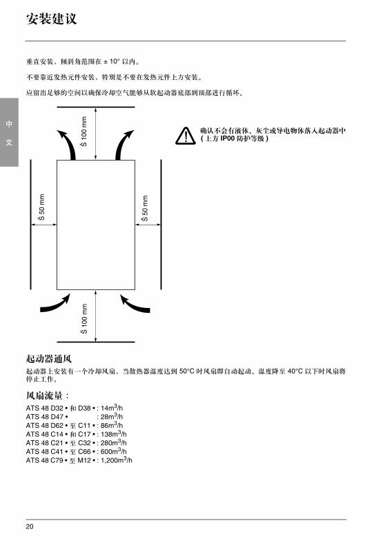
安装建议
垂直安装,倾斜角范围在 ± 10° 以内。
不要靠近发热元件安装,特别是不要在发热元件上方安装。
应留出足够的空间以确保冷却空气能够从软起动器底部到顶部进行循环。
确认不会有液体、灰尘或导电物体落入起动器中( 上方 IP00 防护等级 )
起动器通风
起动器上安装有一个冷却风扇,当散热器温度达到 50°C 时风扇即自动起动。温度降至 40°C 以下时风扇将停止工作。
风扇流量 :
ATS 48 D32 • 和 D38 • : 14m3/hATS 48 D47 • : 28m3/hATS 48 D62 • 至 C11 • : 86m3/hATS 48 C14 • 和 C17 • : 138m3/hATS 48 C21 • 至 C32 • : 280m3/hATS 48 C41 • 至 C66 • : 600m3/hATS 48 C79 • 至 M12 • : 1,200m3/h
Š 1
00 m
m
Š 5
0 m
m
Š 5
0 m
m
Š 1
00 m
m
21
中
文
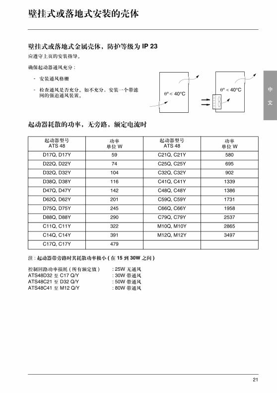
壁挂式或落地式安装的壳体
壁挂式或落地式金属壳体,防护等级为 IP 23应遵守上页的安装指导。
确保起动器通风充分 :
- 安装通风格栅
- 检查通风是否充分。如不充分,安装一个带滤网的强迫通风装置。
起动器耗散的功率,无旁路,额定电流时
注 : 起动器带旁路时其耗散功率极小 ( 在 15 到 30W 之间 )
控制回路功率损耗 ( 所有额定值 ) : 25W 无通风
ATS48D32 至 C17 Q/Y : 30W 带通风
ATS48C21 至 D32 Q/Y : 50W 带通风
ATS48C41 至 M12 Q/Y : 80W 带通风
起动器型号ATS 48
功率单位 W
起动器型号ATS 48
功率单位 W
D17Q, D17Y 59 C21Q, C21Y 580
D22Q, D22Y 74 C25Q, C25Y 695
D32Q, D32Y 104 C32Q, C32Y 902
D38Q, D38Y 116 C41Q, C41Y 1339
D47Q, D47Y 142 C48Q, C48Y 1386
D62Q, D62Y 201 C59Q, C59Y 1731
D75Q, D75Y 245 C66Q, C66Y 1958
D88Q, D88Y 290 C79Q, C79Y 2537
C11Q, C11Y 322 M10Q, M10Y 2865
C14Q, C14Y 391 M12Q, M12Y 3497
C17Q, C17Y 479
22
中
文
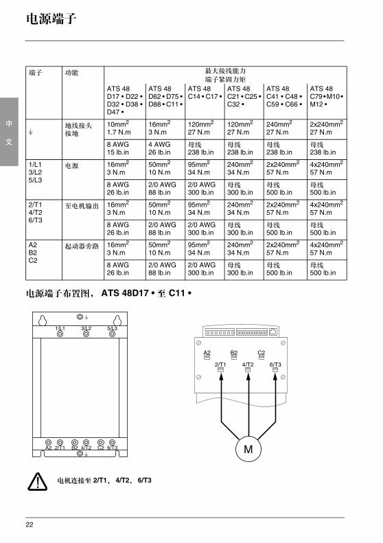
电源端子
电源端子布置图, ATS 48D17 • 至 C11 •
电机连接至 2/T1、 4/T2、 6/T3
端子 功能 最大接线能力
端子紧固力矩
ATS 48D17 • D22 •D32 • D38 •D47 •
ATS 48D62 • D75 •D88 • C11 •
ATS 48C14 • C17 •
ATS 48C21 • C25 •C32 •
ATS 48C41 • C48 •C59 • C66 •
ATS 48C79 • M10 • M12 •
s地线接头接地
10mm2
1.7 N.m16mm2
3 N.m120mm2
27 N.m120mm2
27 N.m240mm2
27 N.m2x240mm2
27 N.m
8 AWG15 lb.in
4 AWG26 lb.in
母线238 lb.in
母线238 lb.in
母线238 lb.in
母线238 lb.in
1/L13/L25/L3
电源 16mm2
3 N.m50mm2
10 N.m95mm2
34 N.m240mm2
34 N.m2x240mm2
57 N.m4x240mm2
57 N.m
8 AWG26 lb.in
2/0 AWG88 lb.in
2/0 AWG300 lb.in
母线300 lb.in
母线500 lb.in
母线500 lb.in
2/T14/T26/T3
至电机输出 16mm2
3 N.m50mm2
10 N.m95mm2
34 N.m240mm2
34 N.m2x240mm2
57 N.m4x240mm2
57 N.m
8 AWG26 lb.in
2/0 AWG88 lb.in
2/0 AWG300 lb.in
母线300 lb.in
母线500 lb.in
母线500 lb.in
A2B2C2
起动器旁路 16mm2
3 N.m50mm2
10 N.m95mm2
34 N.m240mm2
34 N.m2x240mm2
57 N.m4x240mm2
57 N.m
8 AWG26 lb.in
2/0 AWG88 lb.in
2/0 AWG300 lb.in
母线300 lb.in
母线500 lb.in
母线500 lb.in
23
中
文
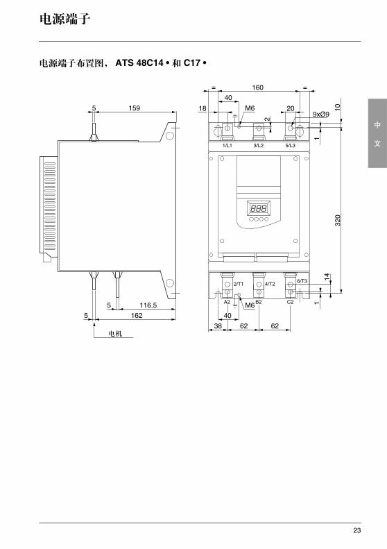
电源端子
电源端子布置图, ATS 48C14 • 和 C17 •
24
中
文
电源端子
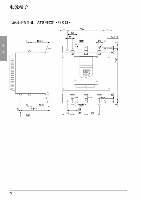
电源端子布置图, ATS 48C21 • 和 C32 •
25
中
文
电源端子
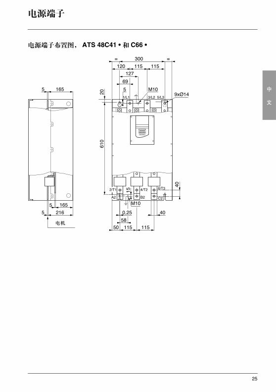
电源端子布置图, ATS 48C41 • 和 C66 •
电机
26
中
文
电源端子
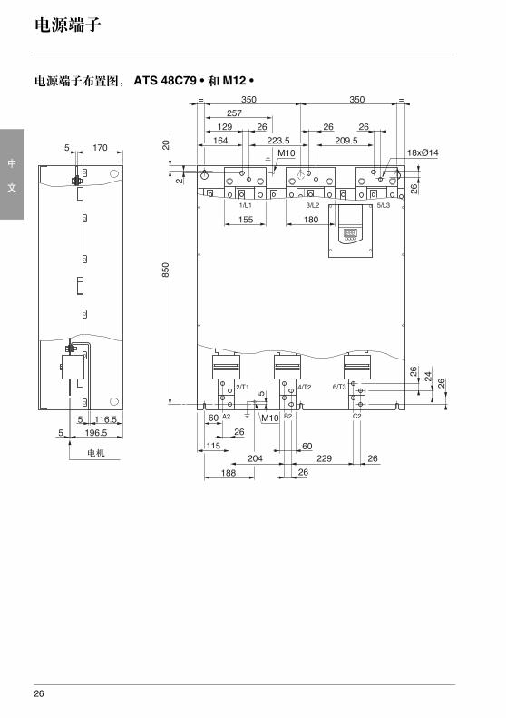
电源端子布置图, ATS 48C79 • 和 M12 •
115
27
中
文
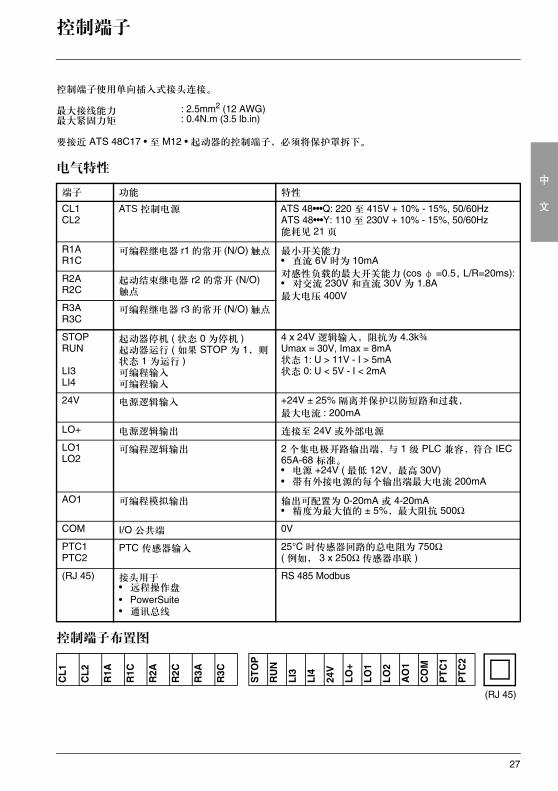
控制端子
控制端子使用单向插入式接头连接。
要接近 ATS 48C17 • 至 M12 • 起动器的控制端子,必须将保护罩拆下。
电气特性
控制端子布置图
最大接线能力 : 2.5mm2 (12 AWG)最大紧固力矩 : 0.4N.m (3.5 lb.in)
端子 功能 特性
CL1CL2
ATS 控制电源 ATS 48•••Q: 220 至 415V + 10% - 15%, 50/60HzATS 48•••Y: 110 至 230V + 10% - 15%, 50/60Hz能耗见 21 页
R1AR1C
可编程继电器 r1 的常开 (N/O) 触点 最小开关能力• 直流 6V 时为 10mA对感性负载的最大开关能力 (cos φ =0.5,L/R=20ms):• 对交流 230V 和直流 30V 为 1.8A最大电压 400V
R2AR2C
起动结束继电器 r2 的常开 (N/O) 触点
R3AR3C
可编程继电器 r3 的常开 (N/O) 触点
STOPRUN
LI3LI4
起动器停机 ( 状态 0 为停机 )起动器运行 ( 如果 STOP 为 1,则状态 1 为运行 )可编程输入可编程输入
4 x 24V 逻辑输入,阻抗为 4.3k¾Umax = 30V, Imax = 8mA状态 1: U > 11V - I > 5mA状态 0: U < 5V - I < 2mA
24V 电源逻辑输入 +24V ± 25% 隔离并保护以防短路和过载,
最大电流 : 200mA
LO+ 电源逻辑输出 连接至 24V 或外部电源
LO1LO2
可编程逻辑输出 2 个集电极开路输出端,与 1 级 PLC 兼容,符合 IEC 65A-68 标准。• 电源 +24V ( 最低 12V,最高 30V)• 带有外接电源的每个输出端最大电流 200mA
AO1 可编程模拟输出 输出可配置为 0-20mA 或 4-20mA• 精度为最大值的 ± 5%,最大阻抗 500Ω
COM I/O 公共端 0V
PTC1PTC2
PTC 传感器输入 25°C 时传感器回路的总电阻为 750Ω( 例如, 3 x 250Ω 传感器串联 )
(RJ 45) 接头用于• 远程操作盘
• PowerSuite• 通讯总线
RS 485 Modbus
CL1
CL2
R1A
R1C
R2A
R2C
R3A
R3C
STO
P
RU
N
LI3
LI4
24V
LO+
LO1
LO2
AO
1
CO
M
PTC
1
PTC
2
(RJ 45)
28
中
文
接线 /RUN-STOP ( 运行 - 停机 ) 命令
接线指导
电源接线
按照标准中推荐的电缆截面积选用电缆。
起动器必须接地以符合有关漏电流的规范。当安装标准要求使用进线“残余电流设备”用于保护时,必须使用一个 A-Si 类型设备 ( 避免上电过程中出现意外脱扣 )。检查它与其他保护设备的兼容性。如果安装中有若干起动器连接在同一条线上的情况,则每个起动器必须单独接地。如有必要,应安装一个进线电抗器 ( 参见产品目录 )。
动力电缆应与弱电信号 ( 检测器、 PLC、测量仪表、视频、电话 ) 电路保持隔离。
控制接线
控制线与动力电缆应保持隔离。
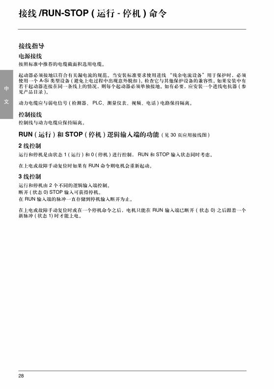
RUN ( 运行 ) 和 STOP ( 停机 ) 逻辑输入端的功能 ( 见 30 页应用接线图 )
2 线控制
运行和停机是由状态 1 ( 运行 ) 和 0 ( 停机 ) 进行控制, RUN 和 STOP 输入状态同时考虑。
在上电或故障手动复位时如果有 RUN 命令则电机会重新起动。
3 线控制
运行和停机由 2 个不同的逻辑输入端控制。
断开 ( 状态 0) STOP 输入可获得停机。
在 RUN 输入端的脉冲一直存储到停机输入断开为止。
在上电或故障手动复位时或在一个停机命令之后,电机只能在 RUN 输入端已断开 ( 状态 0) 之后跟着一个新脉冲 ( 状态 1) 时才能上电。
29
中
文
应用接线图
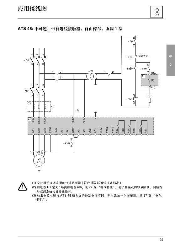
ATS 48: 不可逆,带有进线接触器,自由停车,协调 1 型
(1) 安装用于协调 2 型的快速熔断器 ( 符合 IEC 60 947-4-2 标准 )(2) 继电器 R1 定义 : 隔离继电器 (rll)。见 27 页“电气特性”。要了解触点的容量限制,例如当
与高额定值接触器连接时。
(3) 如果电源电压与 ATS 48 所允许的控制电压不同,则应添加一个变压器。见 27 页 “电气
特性”。
紧急停止
30
中
文
应用接线图
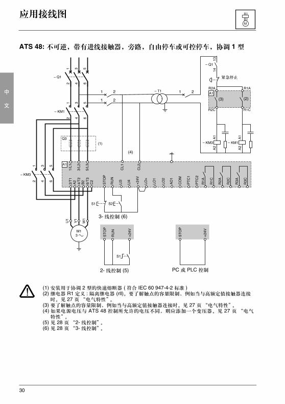
ATS 48: 不可逆,带有进线接触器,旁路,自由停车或可控停车,协调 1 型
(1) 安装用于协调 2 型的快速熔断器 ( 符合 IEC 60 947-4-2 标准 )(2) 继电器 R1 定义 : 隔离继电器 (rll)。要了解触点的容量限制,例如当与高额定值接触器连接
时。见 27 页“电气特性”。(3) 要了解触点的容量限制,例如当与高额定值接触器连接时。见 27 页“电气特性”。(4) 如果电源电压与 ATS 48 控制所允许的电压不同,则应添加一个变压器。见 27 页 “电气
特性”。(5) 见 28 页“2- 线控制”。(6) 见 28 页“3- 线控制”。
紧急停止
3- 线控制 (6)
2- 线控制 (5) PC 或 PLC 控制
31
中
文
应用接线图
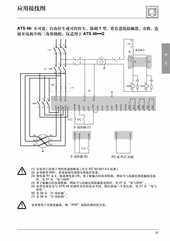
ATS 48: 不可逆,自由停车或可控停车,协调 1 型,带有进线接触器,旁路,连
接至电机中的三角形绕组,仅适用于 ATS 48•••Q
(1) 安装用于协调 2 型的快速熔断器 ( 符合 IEC 60 947-4-2 标准 )(2) 必须使用 KM1,需要添加外部微分热保护装置。(3) 继电器 R1 定义 : 隔离继电器 (rll)。要了解触点的容量限制,例如当与高额定值接触器连接
时。见 27 页“电气特性”。(4) 要了解触点的容量限制,例如当与高额定值接触器连接时。见 27 页“电气特性”。(5) 如果电源电压与 ATS 48 控制所允许的电压不同,则应添加一个变压器。见 27 页 “电气
特性”。(6) 见 28 页 “2- 线控制”。(7) 见 28 页 “3- 线控制”。
如果使用了旁路接触器,则“PHF”故障检测仍然有效。
2- 线控制 (6) PC 或 PLC 控制
3- 线控制 (7)
紧急停止
32
中
文
应用接线图
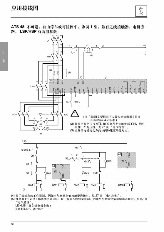
ATS 48: 不可逆,自由停车或可控停车,协调 1 型,带有进线接触器,电机旁路, LSP/HSP 有两组参数
(4) 要了解触点的工作限制,例如当与高额定值接触器连接时。见 27 页“电气特性”。(5) 继电器 R1 定义 : 隔离继电器 (rll)。要了解触点的容量限制,例如当与高额定值接触器连接时。见 27 页
“电气特性”。LI3=LIS ( 第 2 组电机参数 )S3: 1=LSP, 2=HSP
(1) 在协调 2 型情况下安装快速熔断器 ( 符合 IEC 60 947-4-2 标准 )
(2) 如果电源电压与 ATS 48 控制所允许的电压不同,则应添加一个变压器。见 27 页“电气特性”。
(3) 应确保电机转动方向与两种速度均能对应。
紧急停止
33
中
文
应用接线图
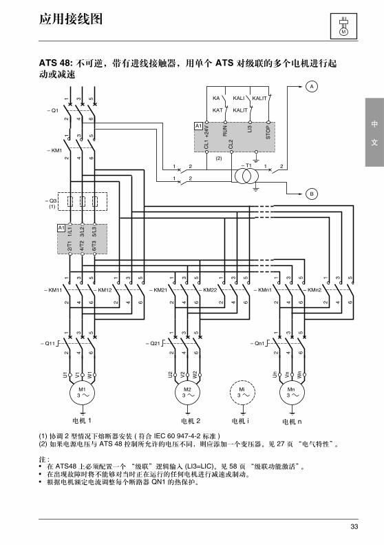
ATS 48: 不可逆,带有进线接触器,用单个 ATS 对级联的多个电机进行起动或减速
(1) 协调 2 型情况下熔断器安装 ( 符合 IEC 60 947-4-2 标准 )(2) 如果电源电压与 ATS 48 控制所允许的电压不同,则应添加一个变压器。见 27 页“电气特性”。
注 :• 在 ATS48 上必须配置一个 “级联”逻辑输入 (LI3=LIC)。见 58 页“级联功能激活”。• 在出现故障时将不能够对当时正在运行的任何电机进行减速或制动。• 根据电机额定电流调整每个断路器 QN1 的热保护。
电机 2 电机 n电机 i电机 1
34
中
文
应用接线图
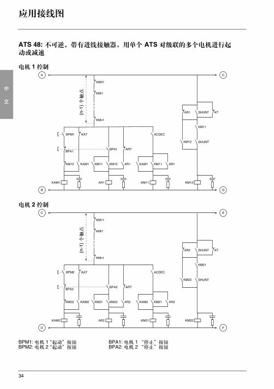
ATS 48: 不可逆,带有进线接触器,用单个 ATS 对级联的多个电机进行起动或减速
电机 1 控制
电机 2 控制
BPM1: 电机 1“起动”按钮 BPA1: 电机 1 “停止”按钮BPM2: 电机 2“起动”按钮 BPA2: 电机 2 “停止”按钮
(n-1
) 个触点
(n-1
) 个触点
35
中
文
应用接线图
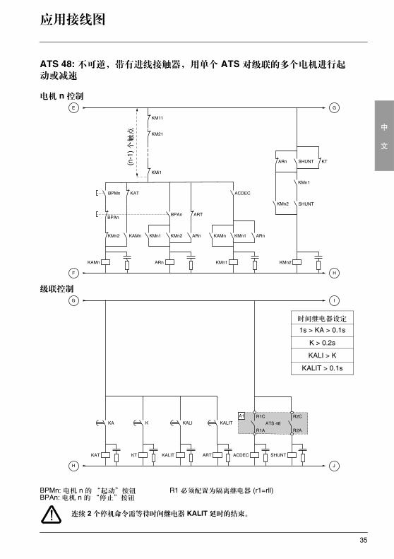
ATS 48: 不可逆,带有进线接触器,用单个 ATS 对级联的多个电机进行起动或减速
电机 n 控制
级联控制
连续 2 个停机命令需等待时间继电器 KALIT 延时的结束。
BPMn: 电机 n 的“起动”按钮 R1 必须配置为隔离继电器 (r1=rll)BPAn: 电机 n 的“停止”按钮
(n-1
) 个触点
时间继电器设定
1s > KA > 0.1s
K > 0.2s
KALI > K
KALIT > 0.1s
36
中
文
应用接线图
ATS 48: 不可逆,带有进线接触器,用单个 ATS 对级联的多个电机进行起动或减速
级联控制
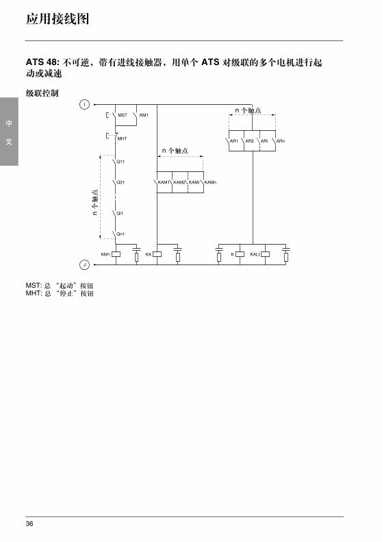
MST: 总 “起动”按钮MHT: 总“停止”按钮
n 个触点
n 个触点
n 个触点
37
中
文
应用接线图
ATS 48: 不可逆,带有进线接触器,用单个 ATS对级联的多个电机进行起动或减速
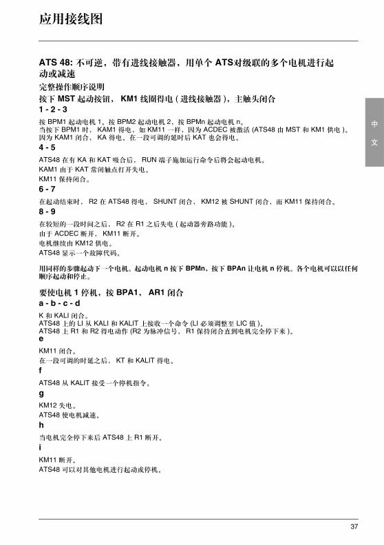
完整操作顺序说明
按下 MST 起动按钮, KM1 线圈得电 ( 进线接触器 ),主触头闭合
1 - 2 - 3按 BPM1 起动电机 1。按 BPM2 起动电机 2,按 BPMn 起动电机 n。当按下 BPM1 时, KAM1 得电,如 KM11 一样,因为 ACDEC 被激活 (ATS48 由 MST 和 KM1 供电 )。因为 KAM1 闭合, KA 得电。在一段可调的延时后 KAT 也会得电。
4 - 5ATS48 在有 KA 和 KAT 吸合后, RUN 端子施加运行命令后将会起动电机。
KAM1 由于 KAT 常闭触点打开失电。
KM11 保持闭合。
6 - 7在起动结束时, R2 在 ATS48 得电, SHUNT 闭合, KM12 被 SHUNT 闭合,而 KM11 保持闭合。
8 - 9在较短的一段时间之后, R2 在 R1 之后失电 ( 起动器旁路功能 )。由于 ACDEC 断开, KM11 断开。
电机继续由 KM12 供电。
ATS48 显示一个故障代码。
用同样的步骤起动下一个电机。起动电机 n 按下 BPMn,按下 BPAn 让电机 n 停机。各个电机可以以任何顺序起动和停止。
要使电机 1 停机,按 BPA1, AR1 闭合
a - b - c - dK 和 KALI 闭合。ATS48 上的 LI 从 KALI 和 KALIT 上接收一个命令 (LI 必须调整至 LIC 值 )。ATS48 上 R1 和 R2 得电动作 (R2 为脉冲信号, R1 保持闭合直到电机完全停下来 )。eKM11 闭合。
在一段可调的时延之后, KT 和 KALIT 得电。
fATS48 从 KALIT 接受一个停机指令。
gKM12 失电。
ATS48 使电机减速。
h 当电机完全停下来后 ATS48 上 R1 断开。
iKM11 断开。
ATS48 可以对其他电机进行起动或停机。
38
中
文
应用接线图
ATS 48: 不可逆,带有进线接触器,用单个 ATS 对级联的多个电机进行起动或减速
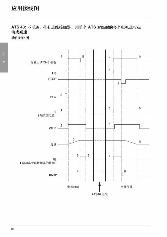
动作时序图
电机由 ATS48 供电
LI3
STOP
RUN
RI( 隔离继电器 )
KM11
速度
R2( 起动器旁路接触器的控制 )
KM12
电机起动 电机停机
ATS48 空闲
39
中
文
热保护
起动器热保护
通过安装在散热器上的 PTC 传感器和计算晶闸管的温升提供热保护。
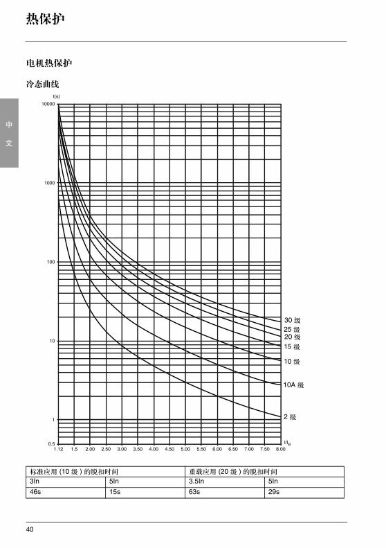
电机热保护
起动器会根据受控制的额定电流 In 和实际吸收的电流持续地计算电机的温升。
温升可能由长时间或短时间的欠载或过载引起。下面几页上的脱扣曲线是基于起动电流 Is 和电机电流 In ( 可调整的 ) 做出的。
IEC60947-4-2 标准定义了保护等级,它给出了电机的无热故障起动能力 ( 热起动或冷起动 )。对 COLD( 冷 ) 状态 ( 对应于稳定的电机热状态,断电 ) 和 WARM ( 热 ) 状态 ( 对应于一个稳定的电机热状态,在额定功率下 ) 给出了不同的保护等级。
起动器出厂设置为 10 级保护。可以使用 PrO 菜单修改保护等级。
起动器显示的热保护对应于加热时间常数 (iron time constant)。- 如果电机超过了其额定温升阈值 ( 电机热状态 =110%) 则激活过载报警。- 如果超过了临界温升阈值 ( 电机热状态 =125%) 热故障将使电机停机。
在出现起动延长时,即使显示的值低于脱扣值起动器也能由故障或热报警脱扣。
如果没有禁止热保护,则热故障可以由继电器 R1 指示。
在电机已经停机或起动器已被断电后,即使控制电路断电也仍然会计算热状态。 ATS 热控制系统可以防止在电机温升过高的情况下重新起动电机。
如果使用特殊的电机 ( 防火、水下的等等 ),则应由 PTC 传感器提供热保护。
40
中
文
热保护
电机热保护
冷态曲线
标准应用 (10 级 ) 的脱扣时间 重载应用 (20 级 ) 的脱扣时间
3In 5In 3.5In 5In
46s 15s 63s 29s
30 级
10A 级
2 级
20 级15 级
10 级
25 级
41
中
文
热保护
电机热保护
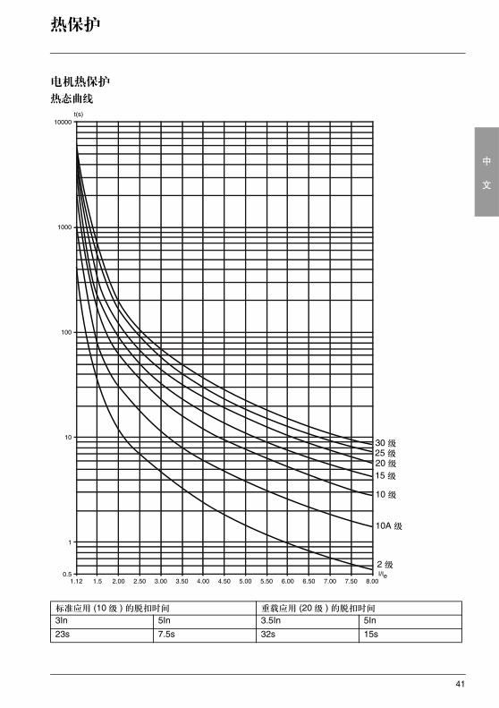
热态曲线
标准应用 (10 级 ) 的脱扣时间 重载应用 (20 级 ) 的脱扣时间
3In 5In 3.5In 5In
23s 7.5s 32s 15s
30 级25 级20 级15 级
10 级
10A 级
2 级

42
中
文
热保护
使用 PTC 传感器的电机热保护
集成在电机中用以测量其温度的 PTC 传感器可以连接到控制卡端口上,这个模拟值由起动器进行管理。
“PTC probe thermal overshoot” (PTC 传感器热过冲 ) 参数值可通过两种方式进行处理和使用 : - 如果该信号有效,出现故障时停机- 如果该信号有效,给出报警。该报警可以显示在起动器状态字 ( 串口 ) 中或可配置逻辑输出
注意 :PTC 传感器保护不会禁止通过计算给出的电机热保护。两种类型的保护可以并行工作。
43
中
文
显示组件和编程
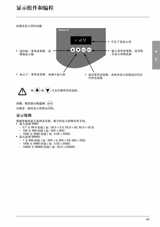
按键及显示屏的功能
按 或 不会存储所作的选择。
存储,保存显示的选项 :
存储某一值时显示屏将会闪烁。
显示规则
根据参数的最大范围及其值,数字的显示原则有所不同。• 最大范围 9990:
- 0.1 至 99.9 的值 ( 如 : 05.5 = 5.5; 55.0 = 55; 55.5 = 55.5)- 100 至 999 的值 ( 如 : 555 = 555) - 1000 至 9990 的值 ( 如 : 5.55 = 5550)
• 最大范围 99900:- 1 至 999 的值 ( 如 : 005 = 5; 055 = 55; 550 = 550)- 1000 至 9990 的值 ( 如 : 5.55 = 5550)- 10000 至 99900 的值 ( 如 : 55.5 = 55500)
• 3 位 7 段显示屏
• 输入菜单或参数,或者保存显示参数或值
• 返回前一菜单或参数,或增加显示值
• 退出菜单或参数,或放弃显示的值返回内存中的先前值
• 显示下一菜单或参数,或减少显示值
ENT
44
中
文
显示组件和编程
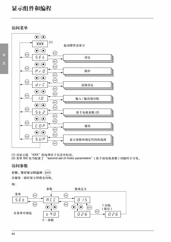
访问菜单
(1) 对显示值“XXX”的处理在下页表中给出。(2) 菜单 St2 仅当配置了“second set of motor parameters” ( 第 2 组电机参数 ) 功能时才可见。
访问参数
存储,保存显示的选项 :
存储某一值时显示屏将会闪烁。
例 :
设定
保护
高级设定
输入 / 输出端分配
第 2 电机参数 (2)
通讯
起动器状态显示
显示参数和锁定代码的选择
ENT
菜单
参数 值或定义
下一参数
1 闪烁( 保存 )
在菜单中浏览
45
中
文
显示组件和编程
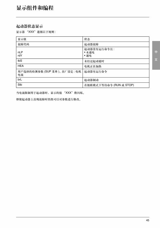
起动器状态显示
显示器 “XXX”遵循以下规则 :
当电流限制用于起动器时,显示的值“XXX”将闪烁。
即使起动器上出现故障时仍然可以对参数进行修改。
显示值 状态
故障代码 起动器故障
nLPrdY
起动器没有运行命令且 :• 未通电• 通电
tbS 未经过起动延时
HEA 电机正在加热
用户选择的检测参数 (SUP 菜单 )。出厂设定 : 电机电流
起动器有运行命令
brL 起动器制动
Stb 在级联模式下等待命令 (RUN 或 STOP)
46
中
文
远程操作盘选件
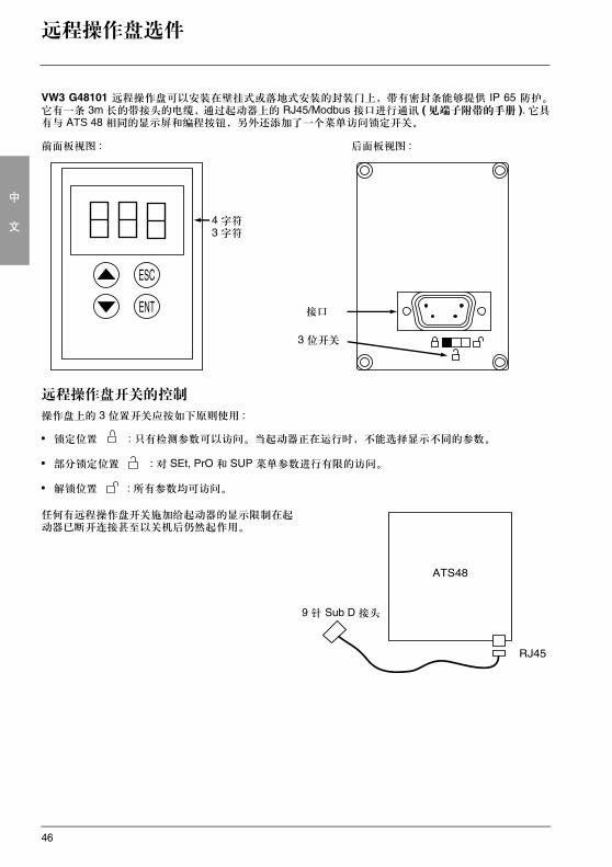
VW3 G48101 远程操作盘可以安装在壁挂式或落地式安装的封装门上,带有密封条能够提供 IP 65 防护。它有一条 3m 长的带接头的电缆,通过起动器上的 RJ45/Modbus 接口进行通讯 ( 见端子附带的手册 ). 它具有与 ATS 48 相同的显示屏和编程按钮,另外还添加了一个菜单访问锁定开关。
前面板视图 : 后面板视图 :
远程操作盘开关的控制
操作盘上的 3 位置开关应按如下原则使用 :
• 锁定位置 : 只有检测参数可以访问。当起动器正在运行时,不能选择显示不同的参数。
• 部分锁定位置 : 对 SEt, PrO 和 SUP 菜单参数进行有限的访问。
• 解锁位置 : 所有参数均可访问。
任何有远程操作盘开关施加给起动器的显示限制在起动器已断开连接甚至以关机后仍然起作用。
4 字符 3 字符
接口
3 位开关
9 针 Sub D 接头
47
中
文
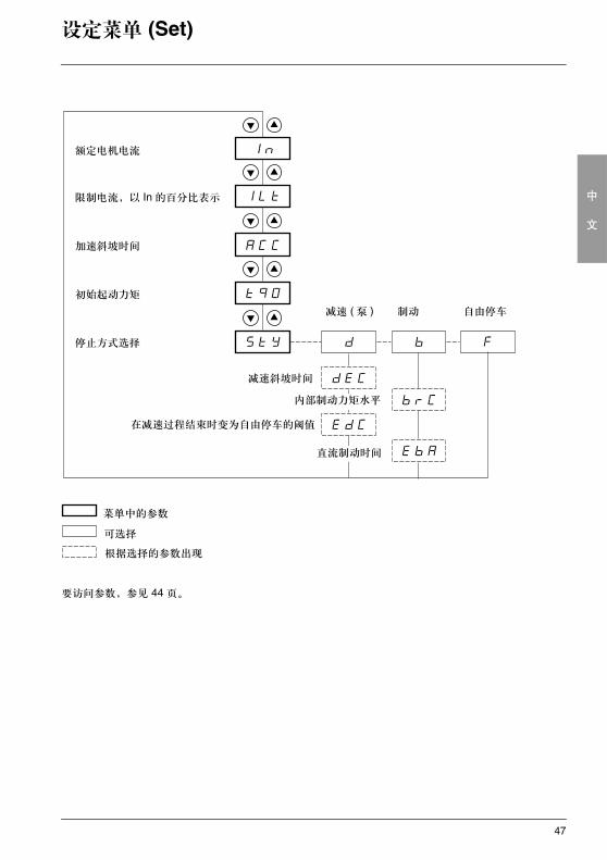
设定菜单 (Set)
要访问参数,参见 44 页。
额定电机电流
限制电流,以 In 的百分比表示
初始起动力矩
加速斜坡时间
停止方式选择
减速 ( 泵 ) 制动 自由停车
减速斜坡时间
菜单中的参数
可选择
根据选择的参数出现
在减速过程结束时变为自由停车的阈值
内部制动力矩水平
直流制动时间
48
中
文
设定菜单 (Set)
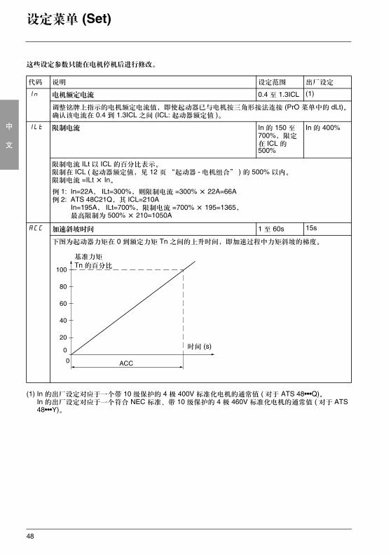
这些设定参数只能在电机停机后进行修改。
(1) In 的出厂设定对应于一个带 10 级保护的 4 极 400V 标准化电机的通常值 ( 对于 ATS 48•••Q)。In 的出厂设定对应于一个符合 NEC 标准、带 10 级保护的 4 极 460V 标准化电机的通常值 ( 对于 ATS 48•••Y)。
代码 说明 设定范围 出厂设定
In 电机额定电流 0.4 至 1.3ICL (1)
调整铭牌上指示的电机额定电流值,即使起动器已与电机按三角形接法连接 (PrO 菜单中的 dLt)。确认该电流在 0.4 到 1.3ICL 之间 (ICL: 起动器额定值 )。
ILt 限制电流 In 的 150 至 700%, 限定在 ICL 的 500%
In 的 400%
限制电流 ILt 以 ICL 的百分比表示。限制在 ICL ( 起动器额定值,见 12 页“起动器 - 电机组合” ) 的 500% 以内。限制电流 =ILt × In。
例 1: In=22A, ILt=300%,则限制电流 =300% × 22A=66A例 2: ATS 48C21Q,其 ICL=210A
In=195A, ILt=700%,限制电流 =700% × 195=1365,最高限制为 500% × 210=1050A
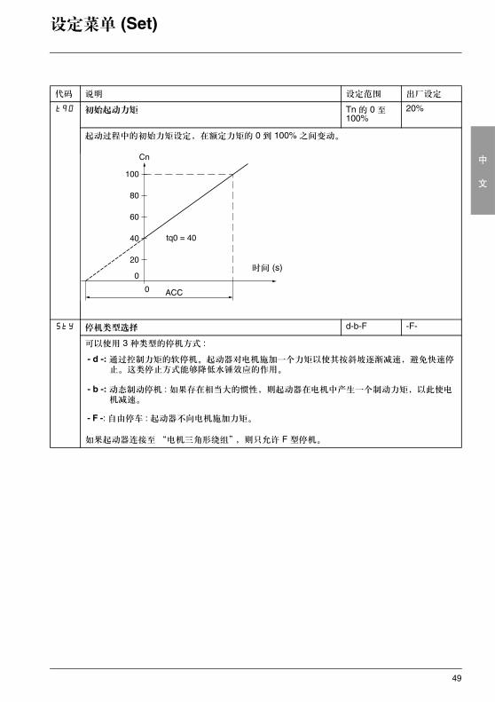
ACC 加速斜坡时间 1 至 60s 15s
下图为起动器力矩在 0 到额定力矩 Tn 之间的上升时间,即加速过程中力矩斜坡的梯度。
时间 (s)
基准力矩
Tn 的百分比
49
中
文
设定菜单 (Set)
代码 说明 设定范围 出厂设定
tq0 初始起动力矩 Tn 的 0 至 100%
20%
起动过程中的初始力矩设定,在额定力矩的 0 到 100% 之间变动。
StY 停机类型选择 d-b-F -F-
可以使用 3 种类型的停机方式 :
- d -: 通过控制力矩的软停机。起动器对电机施加一个力矩以使其按斜坡逐渐减速,避免快速停止。这类停止方式能够降低水锤效应的作用。
- b -: 动态制动停机 : 如果存在相当大的惯性,则起动器在电机中产生一个制动力矩,以此使电机减速。
- F -: 自由停车 : 起动器不向电机施加力矩。
如果起动器连接至 “电机三角形绕组”,则只允许 F 型停机。
时间 (s)
50
中
文
设定菜单 (Set)
代码 说明 设定范围 出厂设定
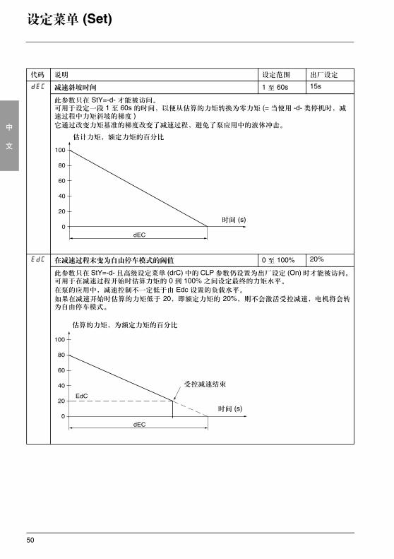
dEC 减速斜坡时间 1 至 60s 15s
此参数只在 StY=-d- 才能被访问。可用于设定一段 1 至 60s 的时间,以便从估算的力矩转换为零力矩 (= 当使用 -d- 类停机时,减速过程中力矩斜坡的梯度 )它通过改变力矩基准的梯度改变了减速过程,避免了泵应用中的液体冲击。
EdC 在减速过程末变为自由停车模式的阈值 0 至 100% 20%
此参数只在 StY=-d- 且高级设定菜单 (drC) 中的 CLP 参数仍设置为出厂设定 (On) 时才能被访问。可用于在减速过程开始时估算力矩的 0 到 100% 之间设定最终的力矩水平。
在泵的应用中,减速控制不一定低于由 Edc 设置的负载水平。
如果在减速开始时估算的力矩低于 20,即额定力矩的 20%,则不会激活受控减速,电机将会转为自由停车模式。
时间 (s)
估计力矩,额定力矩的百分比
时间 (s)
估算的力矩,为额定力矩的百分比
受控减速结束
51
中
文
设定菜单 (Set)
代码 说明 设定范围 出厂设定
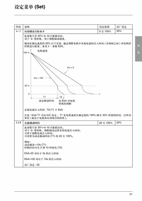
brC 内部制动力矩水平 0 至 100% 50%
此参数只在 StY=-b- 时才能被访问。对于 -b- 类停机,用于调整制动强度。
制动在额定速度的 20% 以下有效。通过调整电机中直流电流的注入时间 ( 在两相之间 ) 对电机的停机进行配置。参见下一参数 EbA。
直流电流注入时间 : T2=T1 × EbA
注意 : 时间 T1 不由 brC 决定。 T1 是电机速度从额定值的 100% 降至 20% 所需的时间,以秒为单位 ( 取决于电机和应用场合的特性 )。
EbA 直流制动时间 20 至 100% 20%
此参数只在 StY=-b- 时才能被访问。对于 -b- 类停机,调整制动过程末的电流注入时间。可用于调整电流注入时间。可设置为动态制动时间 (T1) 的 20 至 100%。
例如 :动态制动 =10s (T1)停机时间可从 2 到 10 秒变化 (T2)
EbA=20 对应于 2s 的注入时间
EbA=100 对应于 10s 的注入时间
出厂设定 : 20
电机速度
动态制动时间 由 EbA 对电机停机的调整
52
中
文
保护菜单 (PrO)
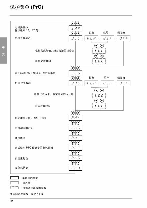
要访问这些参数,参见 44 页。
电机欠载激活
电机热保护保护级别 10、 20 等
报警 故障 使无效
菜单中的参数
可选择
根据选择出现的参数
电机欠载时间
过长起动时间 ( 故障 ),以秒为单位
电流过载激活
报警 故障 使无效
电流过载时间
接受相位反接, 123, 321
重起动前的时间
缺相阈值
激活使用 PTC 传感器的电机监测
自动重起动
复位热状态
电机欠载阈值,额定力矩的百分比
电机过载水平,额定电流的百分比
53
中
文
保护菜单 (PrO)
这些设定参数只能在电机停机后进行修改。
检测报警 (ALA) 配置只能提示存在故障但不能直接对设备进行保护。
代码 说明 设定范围 出厂设定
tHP 电机热保护 10
见 39 页“热保护”。30: 30 级25: 25 级20: 20 级 ( 重载应用 )15: 15 级10: 10 级 ( 标准应用 )10A: 10A 级2: 2 子级
OFF: 无保护
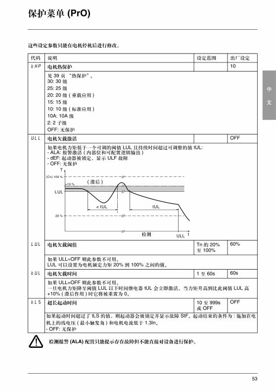
ULL 电机欠载激活 OFF
如果电机力矩低于一个可调的阈值 LUL 且持续时间超过可调整的值 tUL: - ALA: 报警激活 ( 内部位和可配置逻辑输出 )- dEF: 起动器被锁定,显示 ULF 故障- OFF: 无保护
LUL 电机欠载阈值 Tn 的 20% 至 100%
60%
如果 ULL=OFF 则此参数不可用。LUL 可以设置为电机额定力矩 20% 到 100% 之间的值。
tUL 电机欠载时间 1 至 60s 60s
如果 ULL=OFF 则此参数不可用。一旦电机力矩降至阈值 LUL 以下时间继电器 tUL 会立即激活。当力矩升高到比此阈值 LUL 高 +10% ( 滞后作用 ) 时它将被重置为 0。
tLS 超长起动时间 10 至 999s 或 OFF
OFF
如果起动时间超过了 tLS 的值,则起动器会被锁定并显示故障 StF。起动结束的条件为 : 施加在电
机上的线电压 ( 最小触发角 ) 和电机电流低于 1.3In。- OFF: 无保护
( 滞后 )
检测
54
中
文
保护菜单 (PrO)
检测报警 (ALA) 的出厂配置只能提示存在故障但不能直接对设备进行保护。
代码 说明 设定范围 出厂设定
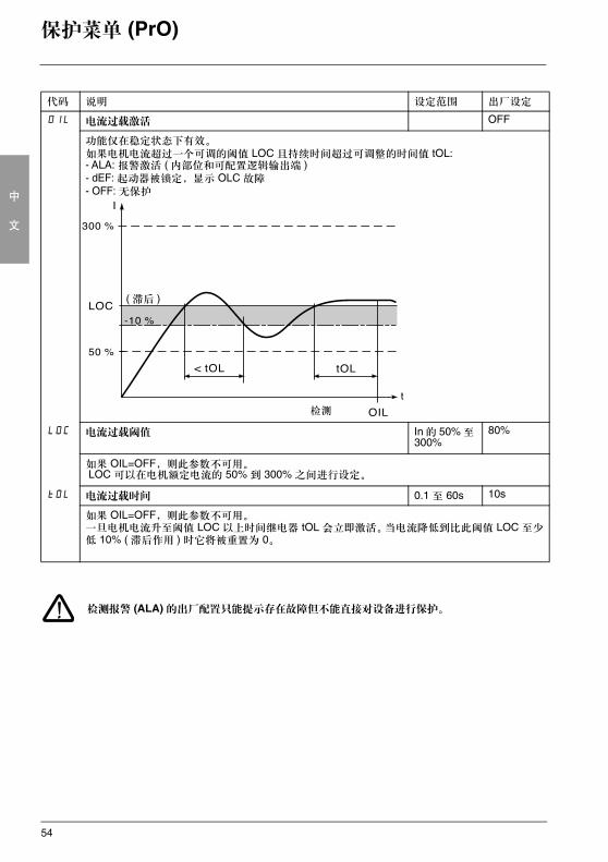
OIL 电流过载激活 OFF
功能仅在稳定状态下有效。如果电机电流超过一个可调的阈值 LOC 且持续时间超过可调整的时间值 tOL:- ALA: 报警激活 ( 内部位和可配置逻辑输出端 )- dEF: 起动器被锁定,显示 OLC 故障- OFF: 无保护
LOC 电流过载阈值 In 的 50% 至 300%
80%
如果 OIL=OFF,则此参数不可用。 LOC 可以在电机额定电流的 50% 到 300% 之间进行设定。
tOL 电流过载时间 0.1 至 60s 10s
如果 OIL=OFF,则此参数不可用。一旦电机电流升至阈值 LOC 以上时间继电器 tOL 会立即激活。当电流降低到比此阈值 LOC 至少低 10% ( 滞后作用 ) 时它将被重置为 0。
( 滞后 )
检测
55
中
文
保护菜单 (PrO)
检测报警 (ALA) 的出厂配置只能提示存在故障但不能直接对设备进行保护。
代码 说明 设定范围 出厂设定
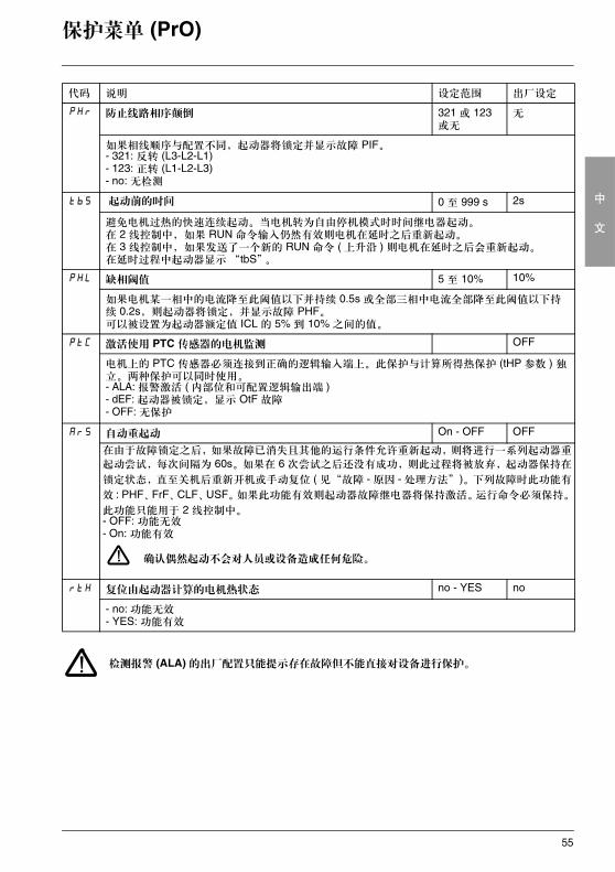
PHr 防止线路相序颠倒 321 或 123 或无
无
如果相线顺序与配置不同,起动器将锁定并显示故障 PIF。- 321: 反转 (L3-L2-L1)- 123: 正转 (L1-L2-L3)- no: 无检测
tbS 起动前的时间 0 至 999 s 2s
避免电机过热的快速连续起动。当电机转为自由停机模式时时间继电器起动。在 2 线控制中,如果 RUN 命令输入仍然有效则电机在延时之后重新起动。在 3 线控制中,如果发送了一个新的 RUN 命令 ( 上升沿 ) 则电机在延时之后会重新起动。在延时过程中起动器显示 “tbS”。
PHL 缺相阈值 5 至 10% 10%
如果电机某一相中的电流降至此阈值以下并持续 0.5s 或全部三相中电流全部降至此阈值以下持续 0.2s,则起动器将锁定,并显示故障 PHF。可以被设置为起动器额定值 ICL 的 5% 到 10% 之间的值。
PtC 激活使用 PTC 传感器的电机监测 OFF
电机上的 PTC 传感器必须连接到正确的逻辑输入端上。此保护与计算所得热保护 (tHP 参数 ) 独立。两种保护可以同时使用。- ALA: 报警激活 ( 内部位和可配置逻辑输出端 )- dEF: 起动器被锁定,显示 OtF 故障- OFF: 无保护
ArS 自动重起动 On - OFF OFF
在由于故障锁定之后,如果故障已消失且其他的运行条件允许重新起动,则将进行一系列起动器重
起动尝试,每次间隔为 60s。如果在 6 次尝试之后还没有成功,则此过程将被放弃,起动器保持在
锁定状态,直至关机后重新开机或手动复位 ( 见“故障 - 原因 - 处理方法”)。下列故障时此功能有
效 : PHF、FrF、CLF、USF。如果此功能有效则起动器故障继电器将保持激活。运行命令必须保持。
此功能只能用于 2 线控制中。- OFF: 功能无效- On: 功能有效
确认偶然起动不会对人员或设备造成任何危险。
rtH 复位由起动器计算的电机热状态 no - YES no
- no: 功能无效- YES: 功能有效
56
中
文
高级设定菜单 (drC)
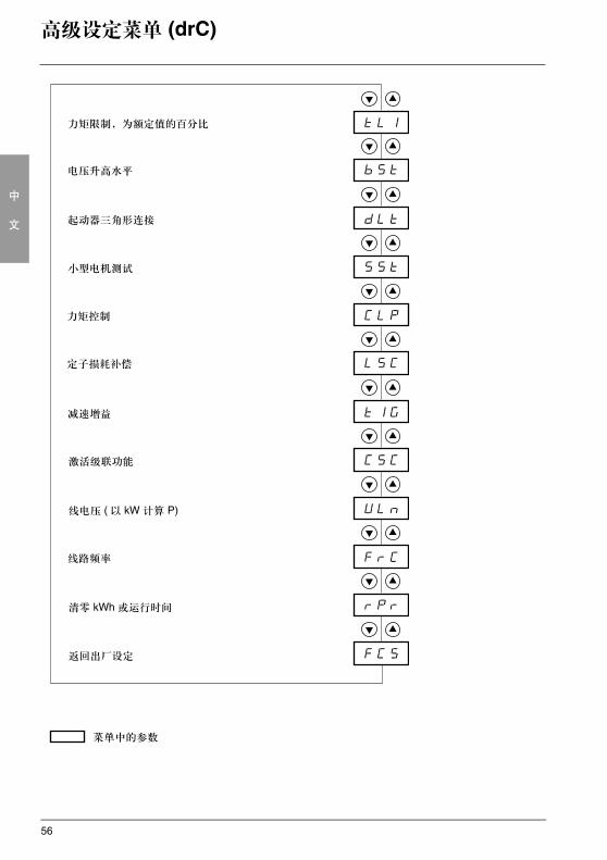
菜单中的参数
力矩限制,为额定值的百分比
电压升高水平
起动器三角形连接
小型电机测试
力矩控制
定子损耗补偿
减速增益
激活级联功能
线电压 ( 以 kW 计算 P)
线路频率
清零 kWh 或运行时间
返回出厂设定
57
中
文
高级设定菜单 (drC)
高级设定参数 (Advanced setting parameters) 只能在电机停机时进行修改。
代码 说明 设定范围 出厂设定
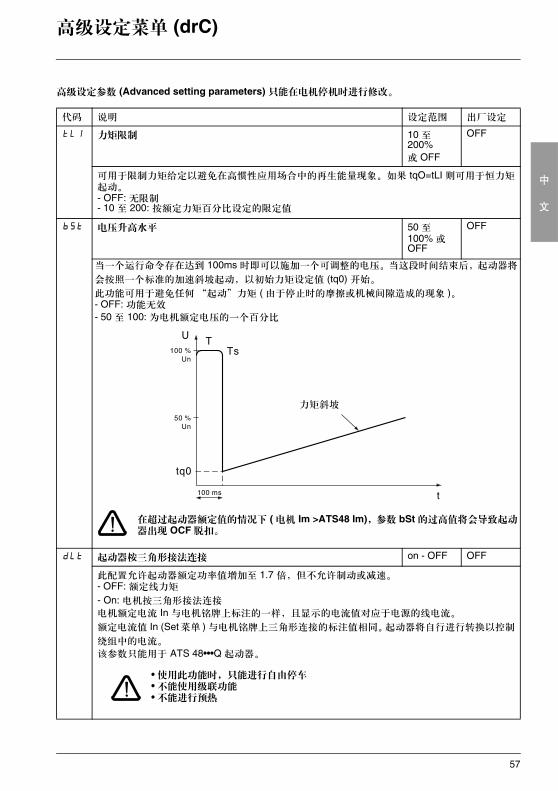
tLI 力矩限制 10 至 200% 或 OFF
OFF
可用于限制力矩给定以避免在高惯性应用场合中的再生能量现象。如果 tqO=tLI 则可用于恒力矩起动。- OFF: 无限制- 10 至 200: 按额定力矩百分比设定的限定值
bSt 电压升高水平 50 至 100% 或 OFF
OFF
当一个运行命令存在达到 100ms 时即可以施加一个可调整的电压。当这段时间结束后,起动器将
会按照一个标准的加速斜坡起动,以初始力矩设定值 (tq0) 开始。
此功能可用于避免任何“起动”力矩 ( 由于停止时的摩擦或机械间隙造成的现象 )。- OFF: 功能无效
- 50 至 100: 为电机额定电压的一个百分比
在超过起动器额定值的情况下 ( 电机 Im >ATS48 Im),参数 bSt 的过高值将会导致起动器出现 OCF 脱扣。
dLt 起动器桉三角形接法连接 on - OFF OFF
此配置允许起动器额定功率值增加至 1.7 倍,但不允许制动或减速。- OFF: 额定线力矩
- On: 电机按三角形接法连接
电机额定电流 In 与电机铭牌上标注的一样,且显示的电流值对应于电源的线电流。
额定电流值 In (Set菜单 ) 与电机铭牌上三角形连接的标注值相同。起动器将自行进行转换以控制
绕组中的电流。
该参数只能用于 ATS 48•••Q 起动器。
• 使用此功能时,只能进行自由停车• 不能使用级联功能• 不能进行预热
力矩斜坡
58
中
文
高级设定菜单 (drC)
代码 说明 设定范围 出厂设定
SSt 小型电机测试 On - OFF OFF
要在测试或维护环境中对起动器进行检查,使用功率远小于起动器额定值的电机 ( 特别是对于大功率的起动器 )。力矩控制参数 CLP 自动无效。- OFF: 功能无效- On: 功能有效控制电压一断开 SSt 即返回 OFF 状态。在下一次起动时, PHF 故障和 CLP 参数将会返回其初始配置。
CLP 力矩控制 ( 控制类型 ) On - OFF On
- OFF: 功能无效- On: 功能有效
在 On 位置,起动和减速按照力矩斜坡进行。在 OFF 位置,起动和减速由电压的变化进行控制。对于多个电机并接在一个起动器上,或电机功率相对于起动器额定值非常小 ( 用小型号电机测试起动器 ) 的情况,建议使用电压控制 (CLP=OFF)。
LSC 定子损耗补偿 0 至 90% 50%
参数在加速阶段 ( 或当 StY=-d- 时的减速阶段 ) 有效。在出现力矩振荡的情况下,应逐步降低这个参数的值,直至设备正常运行为止。在起动器与电机按三角形接法连接或滑差率大的电机中振荡是最常见的现象。
tIG 减速增益 ( 用于力矩控制 ) 10 至 50% 40%
此参数仅在 CLP=On 或 StY 参数 (Set 设定菜单 ) =-d- 时才可访问。可用于消除减速过程中的不稳定性。
应根据振荡情况调整这一参数。
CSC 级联功能激活 On - OFF OFF
见 38 页- On: 功能有效
- OFF: 功能无效
仅当继电器 R1 已事先定义为“隔离继电器”功能,或未配置“强制自由停车”、“起动器三角
形接法”以及“预热”功能时可以访问此参数。
定义一个输入端 LI=LIC。
最多 255 个电机。
ULn 线电压 170 至 460V(ATS48•••Q)180 至 790V(ATS48•••Y)
400V(ATS48•••Q)690V(ATS48•••Y)
此参数用于计算显示的功率 (SUP 菜单中的 LPr 和 LAP 参数 )。此显示仅当该参数已被正确设置时才准确。
59
中
文
高级设定菜单 (drC)
代码 说明 调整范围 出厂设定
FrC 线路频率 50-60-AUt
AUt
- 50: 50Hz ( 频率故障 FrF 检测容许偏差 = ± 20%)。- 60: 60Hz ( 频率故障 FrF 检测容许偏差 = ± 20%)。- AUt: 由起动器自动识别线路频率,频率故障检测容许偏差 FrF= ± 5%。
如果由发电机组提供电源,因其具有较高的频率检测允许偏差,建议选择 50Hz 或 60Hz。
rPr 清零 kWh 或运行时间 no-APH-trE
no
- no: 功能无效- APH: kWh 复位为零- trE: 运行时间复位为零
清零命令必须使用 ENT 进行确认。 APH 和 trE 立即有效。之后此参数自动返回 no 值。
FCS 返回出厂设定 no-YES no
用于将所有的参数返回其出厂设定。- no: 功能无效
- YES: 功能有效,必须被按下并保持一段时间 ( 大约 2s) 以便有效。显示屏会闪烁以示确认。之
后按下 ESC 键可自动将 FCS 参数重置为 no。此参数不能通过远程操作盘进行修改。
60
中
文
I/O 菜单 (IO)
菜单中的参数可选择参数根据选择出现
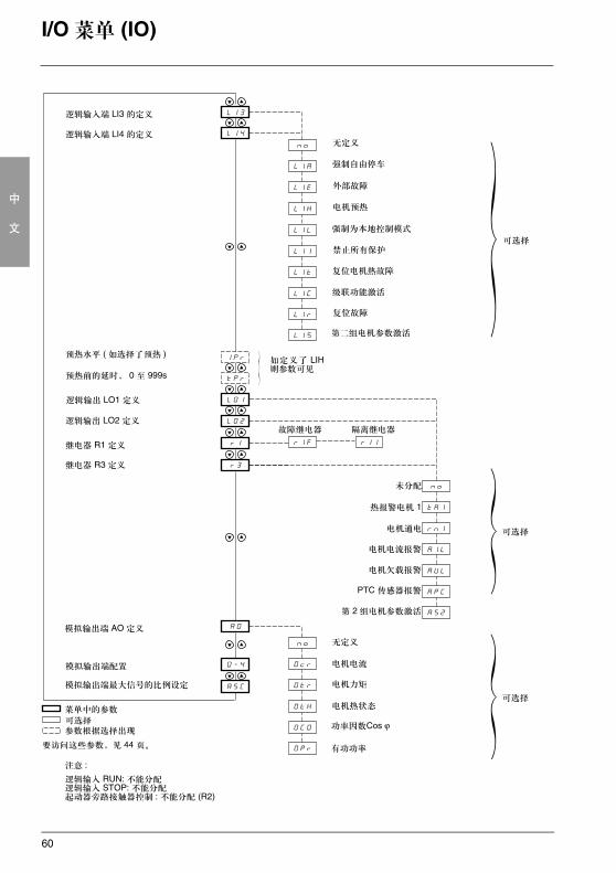
逻辑输入端 LI3 的定义
逻辑输入端 LI4 的定义无定义
强制自由停车
外部故障
电机预热
强制为本地控制模式
禁止所有保护
复位电机热故障
级联功能激活
复位故障
第二组电机参数激活
预热水平 ( 如选择了预热 )
预热前的延时, 0 至 999s
如定义了 LIH则参数可见
故障继电器 隔离继电器
逻辑输出 LO1 定义
逻辑输出 LO2 定义
继电器 R1 定义
继电器 R3 定义
未分配
热报警电机 1
电机通电
电机欠载报警
PTC 传感器报警
第 2 组电机参数激活
模拟输出端 AO 定义
无定义
电机电流
电机力矩
电机热状态
功率因数Cos ϕ
有功功率
模拟输出端配置
模拟输出端最大信号的比例设定
电机电流报警
可选择
可选择
可选择
要访问这些参数,见 44 页。
注意 :
逻辑输入 RUN: 不能分配逻辑输入 STOP: 不能分配起动器旁路接触器控制 : 不能分配 (R2)
61
中
文
I/O 菜单 (IO)
I/O 参数只能在电机停机时进行修改。
(1) 为使此定义生效, ENT 必须按下 10s ( 显示屏闪烁以示确认 )。此参数不能通过远程操作盘进行修改。
代码 说明 设定范围 出厂设定
LI3LI4
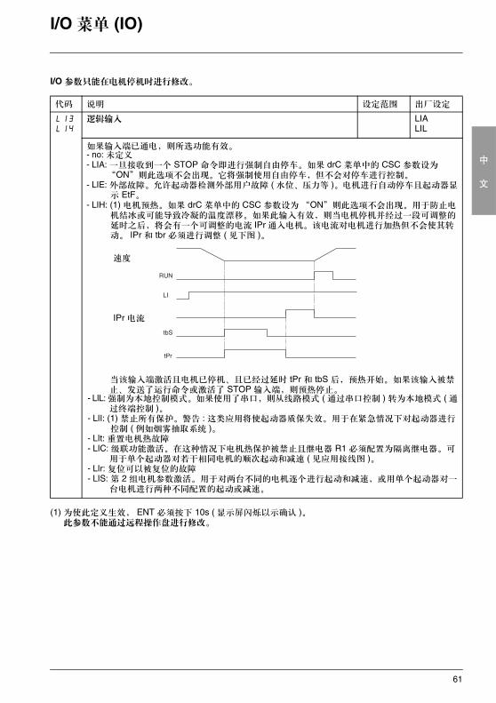
逻辑输入 LIALIL
如果输入端已通电,则所选功能有效。- no: 未定义- LIA: 一旦接收到一个 STOP 命令即进行强制自由停车。如果 drC 菜单中的 CSC 参数设为
“ON”则此选项不会出现。它将强制使用自由停车,但不会对停车进行控制。- LIE: 外部故障。允许起动器检测外部用户故障 ( 水位、压力等 )。电机进行自动停车且起动器显
示 EtF。- LIH: (1) 电机预热。如果 drC 菜单中的 CSC 参数设为“ON”则此选项不会出现。用于防止电
机结冰或可能导致冷凝的温度漂移。如果此输入有效,则当电机停机并经过一段可调整的延时之后,将会有一个可调整的电流 IPr 通入电机。该电流对电机进行加热但不会使其转动。 IPr 和 tbr 必须进行调整 ( 见下图 )。
当该输入端激活且电机已停机、且已经过延时 tPr 和 tbS 后,预热开始。如果该输入被禁止、发送了运行命令或激活了 STOP 输入端,则预热停止。
- LIL: 强制为本地控制模式。如果使用了串口,则从线路模式 ( 通过串口控制 ) 转为本地模式 ( 通过终端控制 )。
- LII: (1) 禁止所有保护。警告 : 这类应用将使起动器质保失效。用于在紧急情况下对起动器进行控制 ( 例如烟雾抽取系统 )。
- LIt: 重置电机热故障- LIC: 级联功能激活。在这种情况下电机热保护被禁止且继电器 R1 必须配置为隔离继电器。可
用于单个起动器对若干相同电机的顺次起动和减速 ( 见应用接线图 )。- LIr: 复位可以被复位的故障- LIS: 第 2 组电机参数激活。用于对两台不同的电机逐个进行起动和减速,或用单个起动器对一
台电机进行两种不同配置的起动或减速。
速度
IPr 电流
RUN
LI
tbS
tPr
62
中
文
I/O 菜单 (IO)
代码 说明 设定范围 出厂设定
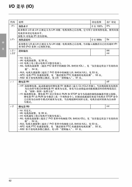
IPr 预热水平 0 至 100% 0%
此参数在 LI3 或 LI4 已被定义为 LIH 功能 : 电机预热之后出现。它可用于设置预热电流。使用真值
电流表来设定电流水平。
参数 In 对电流 IPr 没有影响。
tPr 预热前延时 0 至 999s 5s
此参数在 LI3 或 LI4 已被定义为 LIH 功能 : 电机预热之后出现。当该输入端激活且已经历延时 tPr 和 tbS (PrO 菜单 ) 后预热开始。
LO1LO2
逻辑输出 tAIrnI
- no: 无定义。- tAI: 电机热报警。见 39 页。- rnI: 电机上电 ( 提示电机中可能有电流 )。 - AIL: 电机电流报警(超出 PrO 菜单中的阈值 OIL 和时间 tOL)。见“仅在稳定状态下有效的功
能”, 54 页。
- AUL: 电机欠载报警 ( 超出了 PrO 菜单中的阈值 LUL 和时间 tUL)。见 53 页。- APC: 电机 PTC 传感器报警。见“激活使用 PTC 传感器的电机检测”, 55 页。- AS2: 第 2 组电机参数已激活。见 LIS “逻辑输入”, 61 页。
r1 继电器 R1 rIF
- r1F: 故障继电器。起动器通电时继电器 R1 被激活 ( 最小 CL1/CL2 控制 )。当出现故障及电机转为自由停车模式时继电器 R1 被置为无效。参见当自动重起动功能被激活时的特殊情况以及“故障 - 原因 - 处理方法”。
- r1I: 隔离继电器。继电器 R1 设计用来以 RUN 和 STOP 命令为基础控制线接触器并提示故障。继电器 R1 由 RUN 命令激活 ( 或一个预热命令 )。在制动或减速结束或当电机在 STOP 命令之后转为自由停车模式时被置为无效。当出现故障时同样无效。电机在此时转换为自由停车模式。
r3 继电器 R3 rnI
- no: 未定义。- tAI: 电机热报警。见 39 页。- rnI: 电机通电 ( 指示电机中可能有电流 )。- AIL: 电机电流报警 ( 超出了 PrO 菜单中的阈值 OIL 和时间 tOL)。见“仅在稳定状态下有效的功
能”, 54 页。- AUL: 电机欠载报警 ( 超出了 PrO 菜单中的阈值 LUL 和时间 tUL)。见 53 页。- APC: 电机 PTC 传感器报警。见“激活使用 PTC 传感器的电机检测”, 55 页。- AS2: 第 2 组电机参数已激活。见 LIS “逻辑输入”, 61 页。
63
中
文
I/O 菜单 (IO)
起动结束继电器 R2 ( 不能被定义 )
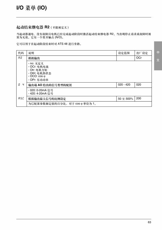
当起动器通电、没有故障且电机已经完成起动阶段时激活起动结束继电器 R2。当出现停止请求或故障时被置为无效。它有一个常开触点 (N/O)。
它可以用于在起动阶段结束时对 ATS 48 进行旁路。
代码 说明 设定范围 出厂设定
AO 模拟输出 OCr
- no: 无定义- OCr: 电机电流- Otr: 电机力矩- OtH: 电机热状态- OCO: cos ϕ- OPr: 有功功率
O 4 输出端 AO 给出的信号类型的配置 020 - 420 020
- 020: 0-20mA 信号- 420: 4-20mA 信号
ASC 模拟输出最大信号的比例设定 50 至 500% 200
为已配置参数额定值的百分比,对于 cos ϕ 单位为 1。
64
中
文
第 2 电机参数菜单 (St2)
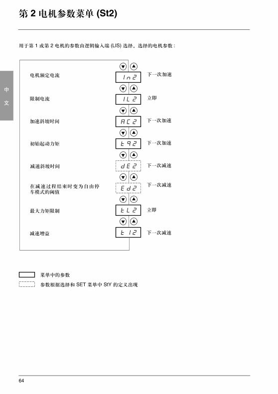
用于第 1 或第 2 电机的参数由逻辑输入端 (LIS) 选择。选择的电机参数 :
菜单中的参数
参数根据选择和 SET 菜单中 StY 的定义出现
电机额定电流
限制电流
加速斜坡时间
初始起动力矩
减速斜坡时间
在减速过程结束时变为自由停车模式的阈值
最大力矩限制
减速增益
下一次减速
下一次减速
下一次加速
立即
下一次加速
下一次加速
立即
下一次减速
65
中
文
第 2 电机参数菜单 (St2)
仅当一个逻辑输入端分配给激活 I/O 菜单中的第 2 组电机参数 (LIS) 的功能时此菜单才可见。
(1) In2 的出厂设定对应于一个带 10 级保护的 4 极 400V 标准化电机的通常值 ( 对于 ATS 48•••Q)。In2 的出厂设定对应于一个符合 NEC 并带有 10 级保护的 460V 标准化电机的通常值 ( 对于 ATS 48•••Y)。
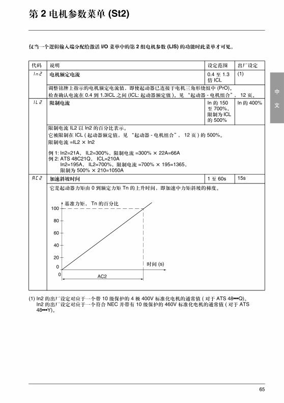
代码 说明 设定范围 出厂设定
In2 电机额定电流 0.4 至 1.3 倍 ICL
(1)
调整铭牌上指示的电机额定电流值,即使起动器已连接于电机三角形绕组中 (PrO)。检查确认电流在 0.4 到 1.3ICL 之间 (ICL: 起动器额定值 )。见 “起动器 - 电机组合”, 12 页。
IL2 限制电流 In 的 150 至 700%,限制为 ICL 的 500%
In 的 400%
限制电流 IL2 以 In2 的百分比表示。
它被限制在 ICL ( 起动器额定值,见“起动器 - 电机组合”, 12 页 ) 的 500%。
限制电流 =IL2 × In2
例 1: In2=21A, IL2=300%,限制电流 =300% × 22A=66A例 2: ATS 48C21Q, ICL=210A
In2=195A, IL2=700%,限制电流 =700% × 195=1365,限制为 500% × 210=1050A
AC2 加速斜坡时间 1 至 60s 15s
它是起动器力矩由 0 到额定力矩 Tn 的上升时间,即加速中力矩斜坡的梯度。
时间 (s)
基准力矩, Tn 的百分比
66
中
文
第 2 电机参数菜单 (St2)
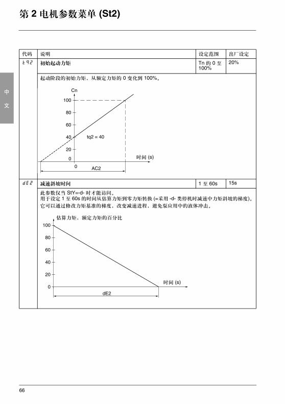
代码 说明 设定范围 出厂设定
tq2 初始起动力矩 Tn 的 0 至 100%
20%
起动阶段的初始力矩,从额定力矩的 0 变化到 100%。
dE2 减速斜坡时间 1 至 60s 15s
此参数仅当 StY=-d- 时才能访问。用于设定 1 至 60s 的时间从估算力矩到零力矩转换 (=采用 -d- 类停机时减速中力矩斜坡的梯度)。它可以通过修改力矩基准的梯度,改变减速进程,避免泵应用中的液体冲击。
时间 (s)
时间 (s)
估算力矩,额定力矩的百分比
67
中
文
第 2 电机参数菜单 (St2)
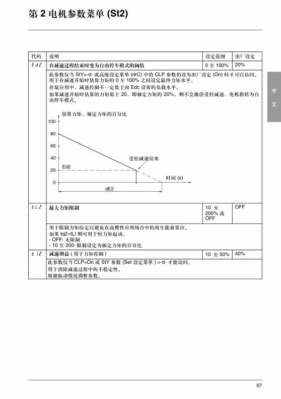
代码 说明 设定范围 出厂设定
Ed2 在减速过程结束时变为自由停车模式的阈值 0 至 100% 20%
此参数仅当 StY=-d- 或高级设定菜单 (drC) 中的 CLP 参数仍设为出厂设定 (On) 时才可以访问。用于在减速开始时估算力矩的 0 至 100% 之间设定最终力矩水平。
在泵应用中,减速控制不一定低于由 Edc 设置的负载水平。
如果减速开始时估算的力矩低于 20,即额定力矩的 20%,则不会激活受控减速,电机将转为自由停车模式。
tL2 最大力矩限制 10 至200% 或 OFF
OFF
用于限制力矩给定以避免在高惯性应用场合中的再生能量效应。 如果 tq2=tLI 则可用于恒力矩起动。- OFF: 无限制- 10 至 200: 限制设定为额定力矩的百分比
tI2 减速增益 ( 用于力矩控制 ) 10 至 50% 40%
此参数仅当 CLP=On 或 StY 参数 (Set 设定菜单 ) =-d- 才能访问。
用于消除减速过程中的不稳定性。
根据振动情况调整参数。
时间 (s)
估算力矩,额定力矩的百分比
受控减速结束
68
中
文
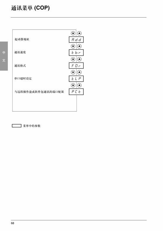
通讯菜单 (COP)
Add
tbr
FOr
tLP
PCt
菜单中的参数
起动器地址
通讯速度
通讯格式
串口超时设定
与远程操作盘或软件包通讯的端口配置
69
中
文
通讯菜单 (COP)
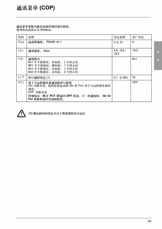
通讯菜单参数只能在电机停机时进行修改。使用的内部协议为 Modbus。
(1) 确认此时间设定不会干扰机器的安全运行
代码 说明 设定范围 出厂设定
Add 起动器地址, RS485 串口 0 至 31 0
tbr 通讯速度, kbps 4.8 - 9.6 - 19.2
19.2
FOr 通讯格式8o1: 8 个数据位,奇校验, 1 个停止位8E1: 8 个数据位,偶校验, 1 个停止位8n1: 8 个数据位,无校验, 1 个停止位8n2: 8 个数据位,无校验, 2 个停止位
8n1
tLP 串口超时设定 (1) 0.1 至 60s 5s
PCt 用于与远程操作盘通讯的串口配置On: 功能有效。临时配置起动器 (tbr 和 For) 用于与远程操作盘的通讯。OFF: 功能无效
控制电压一断开 PCT 即返回 OFF 状态。下一次通电时, tbr 和For 参数将返回其初始配置。
OFF
70
中
文
显示参数菜单 (SUP)
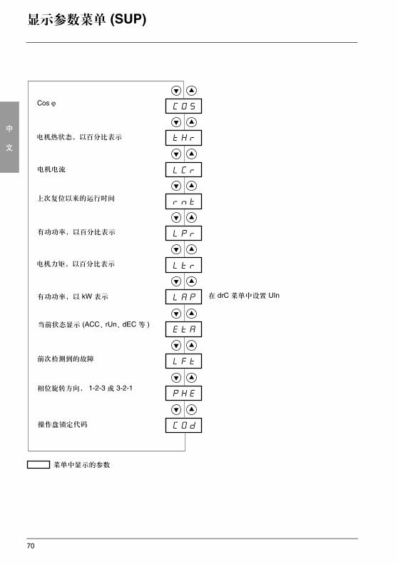
菜单中显示的参数
Cos ϕ
电机热状态,以百分比表示
电机电流
上次复位以来的运行时间
有功功率,以百分比表示
电机力矩,以百分比表示
有功功率,以 kW 表示
当前状态显示 (ACC、rUn、dEC 等 )
相位旋转方向, 1-2-3 或 3-2-1
操作盘锁定代码
在 drC 菜单中设置 UIn
前次检测到的故障
71
中
文
显示参数菜单 (SUP)
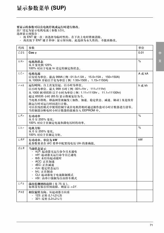
要显示的参数可以在电机停机或运行时进行修改。出厂设定为显示电机电流 ( 参数 LCr)。选择显示项保存 :
- 按 ENT 键一次 : 该选择为临时性的,在下次上电时将被清除。- 再次按下 ENT 键 2 秒钟 : 显示屏闪烁,此选择为永久性的,不能再修改。
代码 参数 单位
COS Cos ϕ 0.01
tHr 电机热状态从 0 变化到 125%100% 对应于电流 In 设定的额定热状态。
%
LCr 电机电流以安培为单位,最高 999A ( 例 : 01.5=1.5A ; 15.0=15A ; 150=150A)从 1000A 开始以千安为单位 ( 例 : 1.50=1500 ; 1.15=1150A)
A 或 kA
rnt 运行时间,自上次复位起,以小时为单位。
以小时为单位,最大 999 小时 ( 例 : 001=1hr ; 111=111hr)从 1000 到 65535 以千小时为单位 ( 例 : 1.11=1110hr ; 11.1=11100hr)超过 65535 小时 (65.5) 显示将被复位为 0。当电机不停机,即晶闸管被触发 ( 加热、加速、稳定状态、减速、制动 ) 及连续旁
路运行时对运行时间进行计数。可以在线控模式中使用控制字或在电机停机时通过操作盘对小时计数器进行清零。当控制部分断电时小时计数器的值被存入 EEPROM 中。
h 或 kh
LPr 有功功率从 0 至 255% 变化。100% 对应于在额定电流和满电压时的功率。
%
Ltr 电机力矩从 0 至 255% 变化。100% 对应于在额定力矩。
%
LAP 有功功率,单位为 kW此参数要求在 drC 菜单中配置线电压 Uln 的准确值。
kW
EtA 当前状态显示- nLP: 起动器无运行命令且未通电- rdY: 起动器无运行命令且已通电- tbS: 未经历起动延时- ACC: 正在加速- dEC: 正在减速- rUn: 稳定状态运行- brL: 正在制动- CLI: 起动器处于电流限制模式- nSt : 由串口强制为自由停车模式
LFt 前次检测到的故障 ( 见 75 页 )。如果没有保存任何故障,则显示 nOF.
PHE 相位旋转方向,从起动器方向看- 123: 正转 (L1-L2-L3)- 321: 反转 (L3-L2-L1)
72
中
文
显示参数菜单 (SUP)
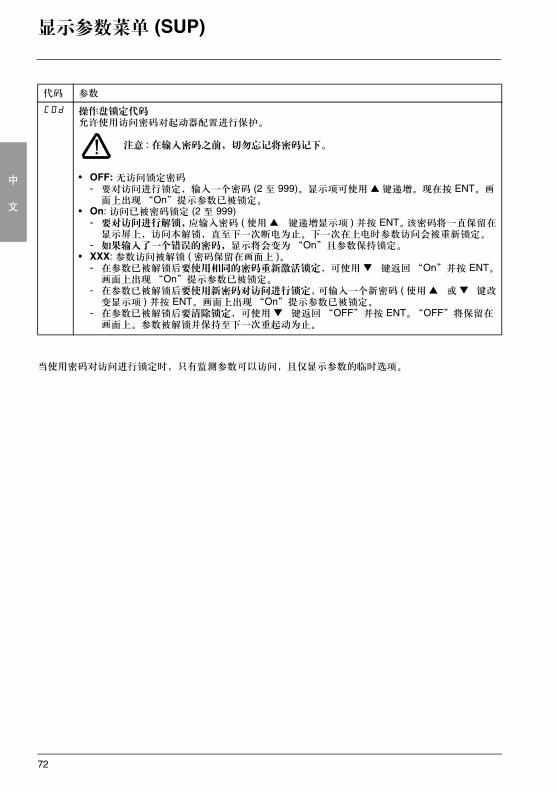
当使用密码对访问进行锁定时,只有监测参数可以访问,且仅显示参数的临时选项。
代码 参数
COd 操作盘锁定代码允许使用访问密码对起动器配置进行保护。
注意 : 在输入密码之前,切勿忘记将密码记下。
• OFF: 无访问锁定密码- 要对访问进行锁定,输入一个密码 (2 至 999)。显示项可使用 键递增。现在按 ENT。画
面上出现“On”提示参数已被锁定。• On: 访问已被密码锁定 (2 至 999)
- 要对访问进行解锁,应输入密码 ( 使用 键递增显示项 ) 并按 ENT。该密码将一直保留在显示屏上,访问本解锁,直至下一次断电为止。下一次在上电时参数访问会被重新锁定。
- 如果输入了一个错误的密码,显示将会变为“On”且参数保持锁定。• XXX: 参数访问被解锁 ( 密码保留在画面上 )。
- 在参数已被解锁后要使用相同的密码重新激活锁定,可使用 键返回“On”并按 ENT。画面上出现“On”提示参数已被锁定。
- 在参数已被解锁后要使用新密码对访问进行锁定,可输入一个新密码 ( 使用 或 键改变显示项 ) 并按 ENT。画面上出现“On”提示参数已被锁定。
- 在参数已被解锁后要清除锁定,可使用 键返回“OFF”并按 ENT。“OFF”将保留在画面上。参数被解锁并保持至下一次重起动为止。
73
中
文
兼容性表
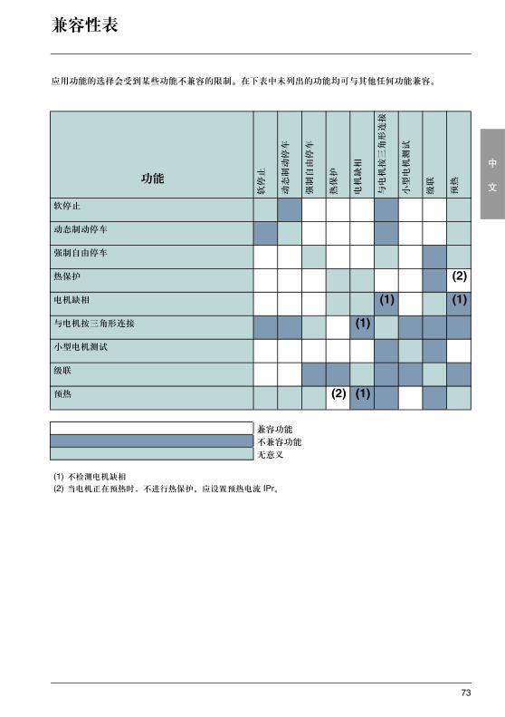
应用功能的选择会受到某些功能不兼容的限制。在下表中未列出的功能均可与其他任何功能兼容。
功能
软停止
动态制动停车
强制自由停车
热保护
电机缺相
与电机按三角形连接
小型电机测试
级联
预热
软停止
动态制动停车
强制自由停车
热保护 (2)
电机缺相 (1) (1)
与电机按三角形连接 (1)
小型电机测试
级联
预热 (2) (1)
兼容功能
不兼容功能
无意义
(1) 不检测电机缺相
(2) 当电机正在预热时,不进行热保护。应设置预热电流 IPr。
74
中
文
维护
维护
ATS 48 不需要任何预防性维护。建议定期进行以下维护工作:
- 检查连接的状态和紧固程度- 确保部件周围的温度保持在可接受的水平而且通风有效 ( 风扇平均寿命:3 至 5 年,取决于运行条件 )- 如有必要应清除散热器上的所有灰尘
维护指南
如果在设置或运行过程中出现问题,应确保遵守与环境、安装和连接相关的规定。
检测到的第一个故障被记忆下来并在屏幕上显示:起动器锁定,继电器 R1 和 R2 根据其定义改变状态。
清除故障
出现不能被复位的故障时应关闭起动器电源。
等待显示屏内容完全消失。
查找故障原因以便排除。
恢复电源 : 如果故障已消除,则此操作可以清除故障状态。
如果已定制了自动重起动功能,则在某些情况下当故障消失后可能会自动重起动。
监测菜单
通过显示起动器状态及其当前参数值来防止和查找故障原因。
备件及修理 请咨询施耐德电气的产品支持部门。
75
中
文
故障 - 原因 - 处理方法
按照常规,如果起动器起动时出现故障,则建议返回出厂设定值并重新按步骤进行设置。
起动器不起动,无故障显示• 无显示:检查控制电源 CL1/CL2 上是否有电源 ( 见 27 页 )。• 检查显示的代码是否与起动器正常状态对应 ( 见 45 页 )。• 检查是否有 RUN/STOP 命令 ( 见 28 页 )。
不能被复位的故障当此类故障出现时,起动器锁定,电机转为自由停车模式。
故障迹象:• 起动结束继电器 R2 断开• 继电器 R1 断开 ( 在起动器锁定之后 )• 显示屏上故障代码闪烁• 存储最近的 5 次故障,使用 PowerSuite 软件包可以查看
重起动条件:• 故障原因消失• 控制电源断开及重新连接
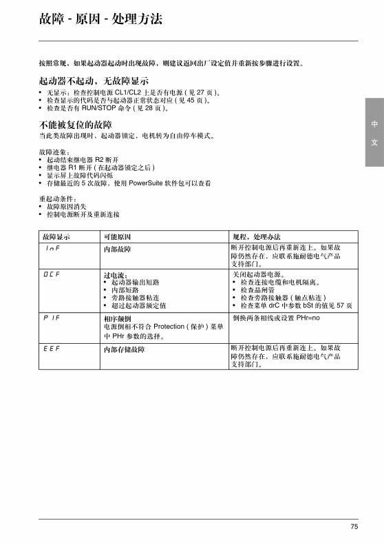
故障显示 可能原因 规程,处理办法
InF 内部故障 断开控制电源后再重新连上。如果故
障仍然存在,应联系施耐德电气产品支持部门。
OCF 过电流:• 起动器输出短路• 内部短路 • 旁路接触器粘连• 超过起动器额定值
关闭起动器电源。• 检查连接电缆和电机隔离。• 检查晶闸管• 检查旁路接触器 ( 触点粘连 )• 检查菜单 drC 中参数 bSt 的值见 57 页
PIF 相序颠倒电源倒相不符合 Protection ( 保护 ) 菜单
中 PHr 参数的选择。
倒换两条相线或设置 PHr=no
EEF 内部存储故障 断开控制电源后再重新连上。如果故
障仍然存在,应联系施耐德电气产品支持部门。
76
中
文
故障 - 原因 - 处理方法
故障原因一消失即可被复位的故障当此类故障出现时,起动器锁定,电机转为自由停车模式。
故障现象:• 起动结束继电器 R2 断开。• 仅当作为隔离继电器时继电器 R1 断开。• 只要故障存在,显示屏上就一直有故障代码闪烁。• 存储最近的 5 次故障,使用 PowerSuite 软件可以查看。
重起动条件:• 故障原因消失• 在 2 线控制中运行命令必须保留在 RUN 输入端。• 在 3 线控制中 RUN 输入端需要有新的运行命令 ( 上升沿 )。
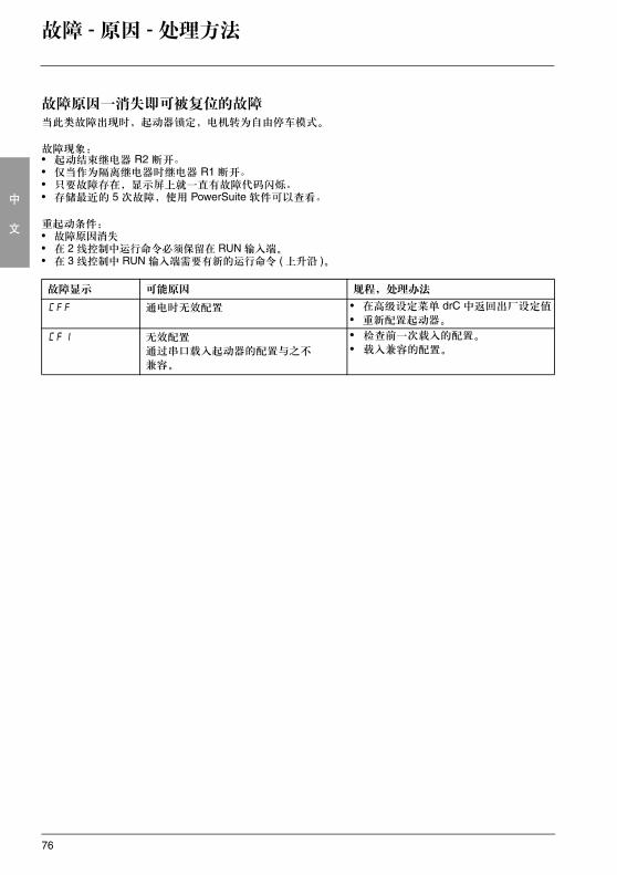
故障显示 可能原因 规程,处理办法
CFF 通电时无效配置 • 在高级设定菜单 drC 中返回出厂设定值
• 重新配置起动器。
CFI 无效配置
通过串口载入起动器的配置与之不
兼容。
• 检查前一次载入的配置。
• 载入兼容的配置。
77
中
文
故障 - 原因 - 处理方法
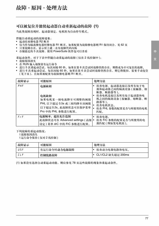
可以被复位并能使起动器自动重新起动的故障 (1)当此类故障出现时,起动器锁定,电机转为自由停车模式。
伴随自动重起动的故障迹象:• 起动结束继电器 R2 断开• 仅当作为隔离继电器时继电器 R1 断开。如果配置为故障继电器则 R1 保持闭合,见 62 页• 只要故障存在,显示屏上就一直有故障代码闪烁• 存储最近的 5 次故障,使用 PowerSuite 软件包可以查看
重起动条件,对于下表中伴随自动重起动的故障 ( 仅在 2 线控制中 ):• 故障原因消失• 在 RUN 输入端保留有运行命令• 进行 5 次重起动尝试,每次间隔 60 秒。如果在第 6 次尝试时故障仍然存在,则将成为不可复位的故障。• 进行 6 次重起动尝试,每次间隔 60 秒。如果在第 6 次尝试时故障仍然存在,则它将脱扣,需要手动复位
( 见下页 ),且如果被配置为故障继电器则 R1 断开。
下列故障的重起动情况: t 故障原因消失 t 运行命令保持 ( 仅对 2 线控制 )
(1) 如果没有选择自动重起动功能,则应参见 78 页这些故障的现象和重起动条件。
故障显示 可能原因 处理方法
PHF 电源缺相
电机缺相
如果电机某一相电流降至可调整的阈值
PHL 以下超过 0.5s 或三相均降至该阈值
以下超过 0.2s。此故障状态可在保护菜单
Pro 中的 PHL 参数进行配置。
• 检查电源、起动器连接以及所有处于电源和起动器之间的隔离设备 ( 接触器、熔断器、断路器等 )。
• 检查电机连接以及所有处于起动器和电机之间的隔离设备 ( 接触器、熔断器、断路器等 )。
• 检查电机状态。• 检查 PHL 参数的配置是否与所使用的电机
匹配。
FrF 电源频率,超出允许范围
此故障状态可在 Advanced settings ( 高级
设定 ) 菜单 drC 中的 FrC 参数进行配置。
• 检查电源。• 检查 FrC 参数的配置是否与所使用的电
源匹配 ( 例如发电机组 )。
故障显示 可能原因 处理方法
USF 有运行命令时动力电源故障 • 检查动力电源电路和电压。
CLF 控制线路故障 • CL1/CL2 缺失超过 200ms
78
中
文
故障 - 原因 - 处理方法
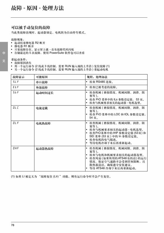
可以被手动复位的故障当此类故障出现时,起动器锁定,电机转为自由停车模式。
故障现象:• 起动结束继电器 R2 断开• 继电器 R1 断开• 只要故障存在,显示屏上就一直有故障代码闪烁• 存储最近的 5 次故障,使用 PowerSuite 软件包可以查看
重起动条件:• 故障原因消失• 用一个运行命令 (2 线或 3 线控制,需要 RUN 输入端的上升沿 ) 复位故障 (1)• 另一个运行命令 (2 线或 3 线控制,需要 RUN 输入端的上升沿 ) 重起动电机
(1) 如果 LI 被定义为“故障复位 (LIr) ”功能,则有运行命令时不会产生复位。
故障显示 可能原因 规程,处理办法
SLF 串口故障 • 检查 RS485 连接。
EtF 外部故障 • 检查已被考虑的故障。
StF 起动时间过长 • 检查机械 ( 磨损情况、机械间隙、润滑、阻塞等 )。
• 检查 PrO 菜单中的 tLs 参数设定值, 53 页。• 检查与机械要求相关的起动器 - 电机选型。
OLC 电流过载 • 检查机械 ( 磨损情况、机械间隙、润滑、阻塞等 )。
• 检查 PrO 菜单中的 LOC 和 tOL 参数设定值,54 页。
OLF 电机热故障 • 检查机械 ( 磨损情况、机械间隙、润滑、阻塞等 )。
• 检查与机械要求相关的起动器 - 电机选型。• 检查PrO菜单中的 tHP 参数设定值 (53页) 和
SEt 菜单 (53 页 ) 中的 In 参数设定值。• 检查电机的电气隔离。• 等待电机冷却下来后再重新起动。
OHF 起动器热故障 • 检查机械 ( 磨损情况、机械间隙、润滑、阻塞等 )。
• 检查与电机和机械要求相关的起动器选型。• 检查风扇 (如果所用的ATS48有的话 ) 的运行
情况,保证空气通路不会受到任何阻断,且散热器清洁。确保遵守安装建议。
• 等待 ATS48 冷却下来后再重新起动。
79
中
文
故障 - 原因 - 处理方法
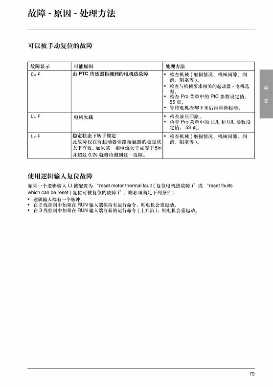
可以被手动复位的故障
使用逻辑输入复位故障
如果一个逻辑输入 LI 被配置为“reset motor thermal fault ( 复位电机热故障 )”或 “reset faults which can be reset ( 复位可被复位的故障 )”,则必须满足下列条件 :• 逻辑输入端有一个脉冲• 在 2 线控制中如果在 RUN 输入端保持有运行命令,则电机会重起动。• 在 3 线控制中如果在 RUN 输入端有新的运行命令 ( 上升沿 ),则电机会重起动。
故障显示 可能原因 处理方法
OtF 由 PTC 传感器检测到的电机热故障 • 检查机械 ( 磨损情况、机械间隙、润滑、阻塞等 )。
• 检查与机械要求相关的起动器 - 电机选型。
• 检查 Pro 菜单中的 PtC 参数设定值,55 页。
• 等待电机冷却下来后再重新起动。
ULF 电机欠载 • 检查液压回路。• 检查 Pro 菜单中的 LUL 和 tUL 参数设
定值, 53 页。
LrF 稳定状态下转子锁定
此故障仅在有起动器旁路接触器的稳定状
态下有效。如果某一相电流大于或等于5In并超过 0.2s 就将检测到这一故障。
• 检查机械 ( 磨损情况、机械间隙、润滑、阻塞等 )。
80
中
文
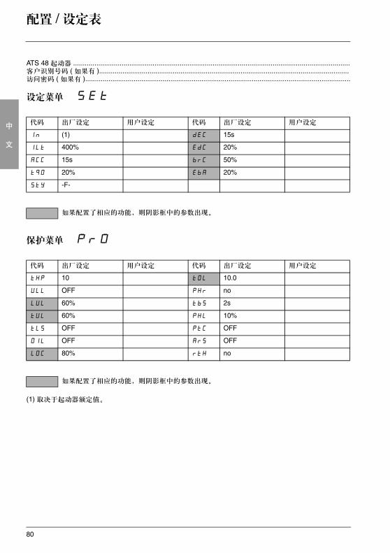
配置 / 设定表
ATS 48 起动器 ...............................................................................................................................................客户识别号码 ( 如果有 ).................................................................................................................................访问密码 ( 如果有 ).........................................................................................................................................
设定菜单 SEt
保护菜单 PrO
(1) 取决于起动器额定值。
代码 出厂设定 用户设定 代码 出厂设定 用户设定
In (1) dEC 15s
ILt 400% EdC 20%
ACC 15s brC 50%
tq0 20% EbA 20%
StY -F-
如果配置了相应的功能,则阴影框中的参数出现。
代码 出厂设定 用户设定 代码 出厂设定 用户设定
tHP 10 tOL 10.0
ULL OFF PHr no
LUL 60% tbS 2s
tUL 60% PHL 10%
tLS OFF PtC OFF
OIL OFF ArS OFF
LOC 80% rtH no
如果配置了相应的功能,则阴影框中的参数出现。
81
中
文
配置 / 设定表
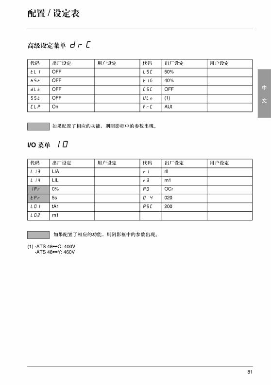
高级设定菜单 drC
I/O 菜单IO
(1) -ATS 48•••Q: 400V-ATS 48•••Y: 460V
代码 出厂设定 用户设定 代码 出厂设定 用户设定
tLI OFF LSC 50%
bSt OFF tIG 40%
dLt OFF CSC OFF
SSt OFF ULn (1)
CLP On FrC AUt
如果配置了相应的功能,则阴影框中的参数出现。
代码 出厂设定 用户设定 代码 出厂设定 用户设定
LI3 LIA r1 rlI
LI4 LIL r3 rn1
IPr 0% AO OCr
tPr 5s O 4 020
LO1 tA1 ASC 200
LO2 rn1
如果配置了相应的功能,则阴影框中的参数出现。
82
中
文
配置 / 设定表
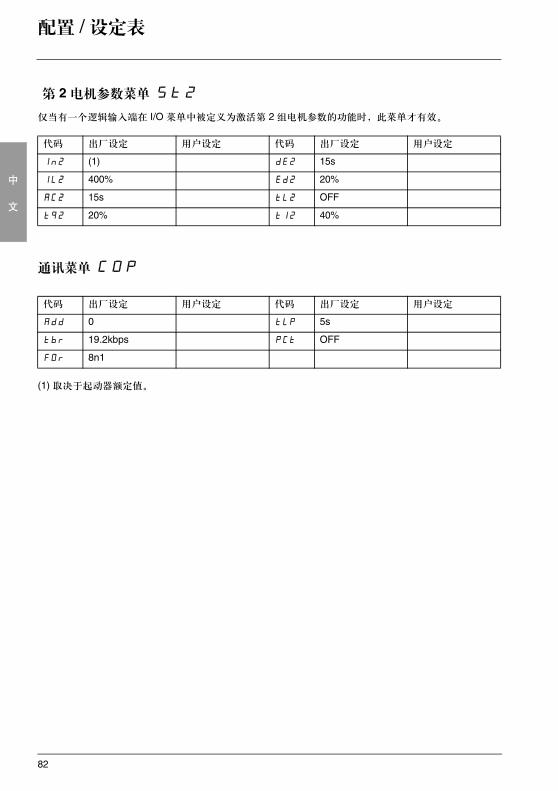
第 2 电机参数菜单 St2仅当有一个逻辑输入端在 I/O 菜单中被定义为激活第 2 组电机参数的功能时,此菜单才有效。
通讯菜单 COP
(1) 取决于起动器额定值。
代码 出厂设定 用户设定 代码 出厂设定 用户设定
In2 (1) dE2 15s
IL2 400% Ed2 20%
AC2 15s tL2 OFF
tq2 20% tI2 40%
代码 出厂设定 用户设定 代码 出厂设定 用户设定
Add 0 tLP 5s
tbr 19.2kbps PCt OFF
FOr 8n1

83
中
文
84
EN
GLI
SH
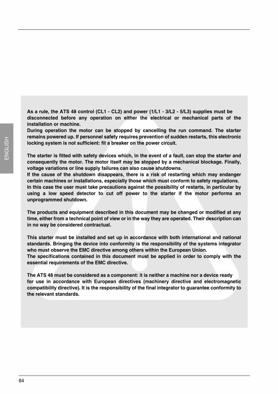
As a rule, the ATS 48 control (CL1 - CL2) and power (1/L1 - 3/L2 - 5/L3) supplies must bedisconnected before any operation on either the electrical or mechanical parts of theinstallation or machine.During operation the motor can be stopped by cancelling the run command. The starterremains powered up. If personnel safety requires prevention of sudden restarts, this electroniclocking system is not sufficient: fit a breaker on the power circuit.
The starter is fitted with safety devices which, in the event of a fault, can stop the starter andconsequently the motor. The motor itself may be stopped by a mechanical blockage. Finally,voltage variations or line supply failures can also cause shutdowns.If the cause of the shutdown disappears, there is a risk of restarting which may endangercertain machines or installations, especially those which must conform to safety regulations.In this case the user must take precautions against the possibility of restarts, in particular byusing a low speed detector to cut off power to the starter if the motor performs anunprogrammed shutdown.
The products and equipment described in this document may be changed or modified at anytime, either from a technical point of view or in the way they are operated. Their description canin no way be considered contractual.
This starter must be installed and set up in accordance with both international and nationalstandards. Bringing the device into conformity is the responsibility of the systems integratorwho must observe the EMC directive among others within the European Union.The specifications contained in this document must be applied in order to comply with theessential requirements of the EMC directive.
The ATS 48 must be considered as a component: it is neither a machine nor a device readyfor use in accordance with European directives (machinery directive and electromagneticcompatibility directive). It is the responsibility of the final integrator to guarantee conformity tothe relevant standards.
85
EN
GLI
SH
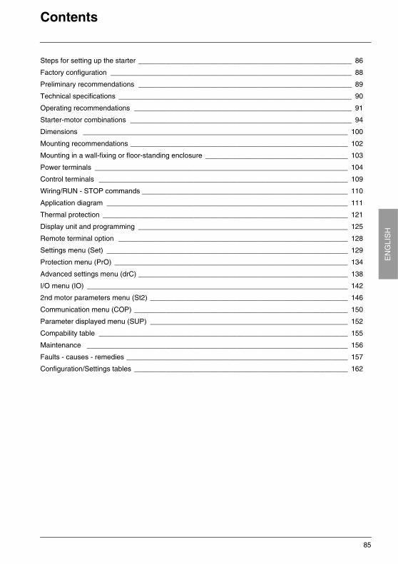
Contents
Steps for setting up the starter ______________________________________________________ 86
Factory configuration _____________________________________________________________ 88
Preliminary recommendations ______________________________________________________ 89
Technical specifications ___________________________________________________________ 90
Operating recommendations _______________________________________________________ 91
Starter-motor combinations ________________________________________________________ 94
Dimensions ___________________________________________________________________ 100
Mounting recommendations _______________________________________________________ 102
Mounting in a wall-fixing or floor-standing enclosure ____________________________________ 103
Power terminals ________________________________________________________________ 104
Control terminals _______________________________________________________________ 109
Wiring/RUN - STOP commands ____________________________________________________ 110
Application diagram _____________________________________________________________ 111
Thermal protection ______________________________________________________________ 121
Display unit and programming _____________________________________________________ 125
Remote terminal option __________________________________________________________ 128
Settings menu (Set) _____________________________________________________________ 129
Protection menu (PrO) ___________________________________________________________ 134
Advanced settings menu (drC) _____________________________________________________ 138
I/O menu (IO) __________________________________________________________________ 142
2nd motor parameters menu (St2) __________________________________________________ 146
Communication menu (COP) ______________________________________________________ 150
Parameter displayed menu (SUP) __________________________________________________ 152
Compability table _______________________________________________________________ 155
Maintenance __________________________________________________________________ 156
Faults - causes - remedies ________________________________________________________ 157
Configuration/Settings tables ______________________________________________________ 162
86
EN
GLI
SH
Steps for setting up the starter
1 – Delivery of the ATS 48• Check that the starter reference printed on the label is the same as that on the delivery note corresponding
to the purchase order.• Remove the ATS 48 from its packaging and check that it has not been damaged in transit.
2 - Fit the ATS 48 in accordance with the recommendations on page 102 and page 103
3 - Connect the following to the ATS 48:• The control line supply (CL1 – CL2), ensuring that it is off• The power line supply (1/L1 - 3/L2 - 5/L3), ensuring that it is off• The motor (2/T1 - 4/T2 - 6/T3), ensuring that its coupling corresponds to the supply voltage
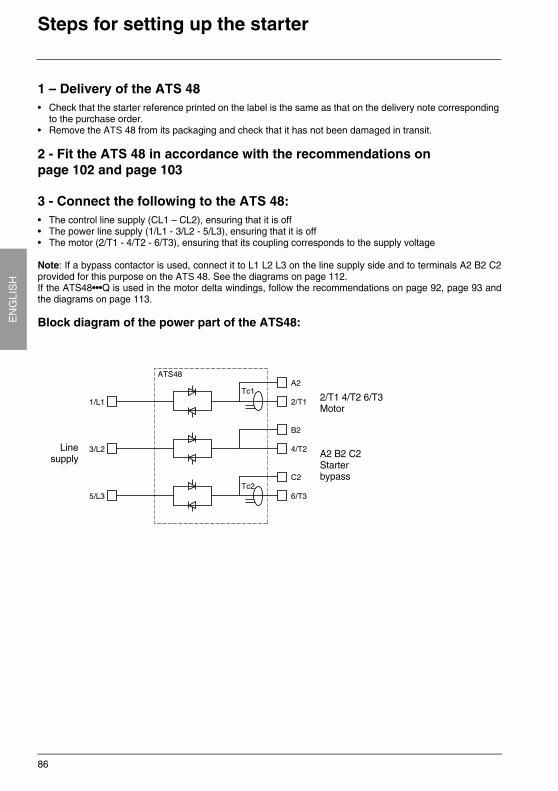
Note: If a bypass contactor is used, connect it to L1 L2 L3 on the line supply side and to terminals A2 B2 C2provided for this purpose on the ATS 48. See the diagrams on page 112.If the ATS48•••Q is used in the motor delta windings, follow the recommendations on page 92, page 93 andthe diagrams on page 113.
Block diagram of the power part of the ATS48:
Linesupply
2/T1 4/T2 6/T3Motor
A2 B2 C2Starterbypass
87
EN
GLIS
HSteps for setting up the starter
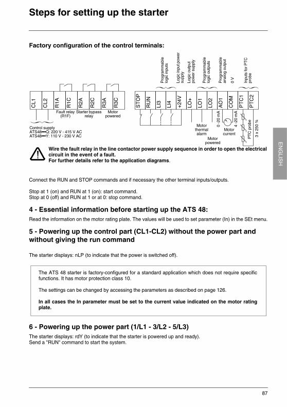
Factory configuration of the control terminals:
Connect the RUN and STOP commands and if necessary the other terminal inputs/outputs.
Stop at 1 (on) and RUN at 1 (on): start command.Stop at 0 (off) and RUN at 1 or at 0: stop command.
4 - Essential information before starting up the ATS 48: Read the information on the motor rating plate. The values will be used to set parameter (In) in the SEt menu.
5 - Powering up the control part (CL1-CL2) without the power part and without giving the run command
The starter displays: nLP (to indicate that the power is switched off).
6 - Powering up the power part (1/L1 - 3/L2 - 5/L3)The starter displays: rdY (to indicate that the starter is powered up and ready).Send a "RUN" command to start the system.
Control supplyATS48•••Q: 220 V - 415 V ACATS48•••Y: 110 V - 230 V AC
Fault relay (R1F)
Starter bypass relay
Motor powered
Pro
gram
mab
le
logi
c in
puts
Logi
c in
put p
ower
su
pply
Logi
c ou
tput
po
wer
sup
ply
Pro
gram
mab
le
logi
c ou
tput
s
Pro
gram
mab
le
anal
og o
utpu
t
Inpu
ts fo
r P
TC
pr
obe
PT
C p
robe
0 -2
0 m
A
4 -2
0 m
A
Motor powered
Motor thermal alarm
Motor current
Wire the fault relay in the line contactor power supply sequence in order to open the electricalcircuit in the event of a fault.For further details refer to the application diagrams.
0 V
3 x
250
¾
The ATS 48 starter is factory-configured for a standard application which does not require specificfunctions. It has motor protection class 10.
The settings can be changed by accessing the parameters as described on page 126.
In all cases the In parameter must be set to the current value indicated on the motor ratingplate.
88
EN
GLI
SH
Factory configuration
Factory settingsThe ATS 48 is factory-set for the most common operating conditions:
• The ATS 48 is used on the motor line supply (it is not inserted as a delta connection in the motor windings)
• Nominal motor current In: - ATS 48 •••Q: preset for a standard 400 V 4-pole motor- ATS 48 •••Y: preset for NEC current, 460 V motor
• Limiting current (ILt): 400% of the motor current In
• Acceleration ramp (ACC): 15 seconds
• Initial torque on starting (tq0): 20% of the nominal torque
• Stop (StY): Freewheel stop (-F-)
• Motor thermal protection (tHP): class 10 protection curve
• Display: rdY (starter ready) with power and control voltage present, motor current operating
• Logic inputs: - LI1: STOP- LI2: RUN- LI3: Forced freewheel stop (LIA)- LI4: Forced local mode (LIL)
• Logic outputs:- LO1: Motor thermal alarm (tA1)- LO2: Motor powered (mI)
• Relay outputs:- R1: Fault relay (r1I)- R2: Bypass relay at the end of starting- R3: Motor powered (mI)
• Analog output:- AO: Motor current (OCr, 0 - 20 mA)
• Communication parameters:
- Connected via the serial link, the starter has the logic address (Add) = "0" - Transmission speed (tbr): 19200 bits per second- Communication format (FOr): 8 bits, no parity, 1 stop bit (8nl)
If the above values are compatible with the application, the starter can be used without changing the settings.
89
EN
GLIS
HPreliminary recommendations
Handling and storageTo ensure the starter is protected before installation, handle and store the device in its packaging.
Handling on installationThe ATS 48 range comprises 6 sizes of device, with various weights and dimensions.
Small starters can be removed from their packaging and installed without a handling device.
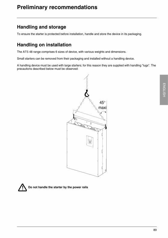
A handling device must be used with large starters; for this reason they are supplied with handling "lugs". The precautions described below must be observed:
Do not handle the starter by the power rails
90
EN
GLI
SH
Technical specifications
Environment
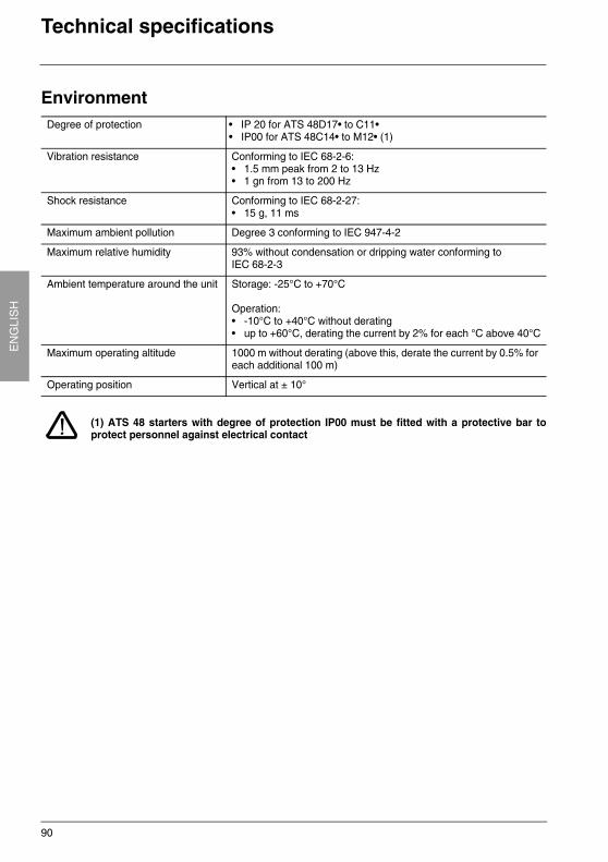
(1) ATS 48 starters with degree of protection IP00 must be fitted with a protective bar toprotect personnel against electrical contact
Degree of protection • IP 20 for ATS 48D17• to C11•• IP00 for ATS 48C14• to M12• (1)
Vibration resistance Conforming to IEC 68-2-6:• 1.5 mm peak from 2 to 13 Hz• 1 gn from 13 to 200 Hz
Shock resistance Conforming to IEC 68-2-27: • 15 g, 11 ms
Maximum ambient pollution Degree 3 conforming to IEC 947-4-2
Maximum relative humidity 93% without condensation or dripping water conforming to IEC 68-2-3
Ambient temperature around the unit Storage: -25°C to +70°C
Operation:• -10°C to +40°C without derating• up to +60°C, derating the current by 2% for each °C above 40°C
Maximum operating altitude 1000 m without derating (above this, derate the current by 0.5% for each additional 100 m)
Operating position Vertical at ± 10°
91
EN
GLIS
HOperating recommendations
Available torque
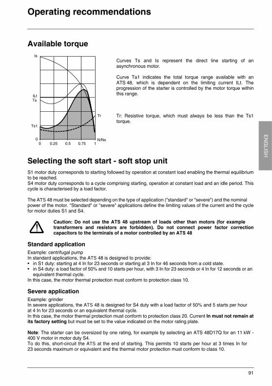
Curves Ts and Is represent the direct line starting of anasynchronous motor.
Curve Ta1 indicates the total torque range available with anATS 48, which is dependent on the limiting current ILt. Theprogression of the starter is controlled by the motor torque withinthis range.
Tr: Resistive torque, which must always be less than the Ts1torque.
Selecting the soft start - soft stop unitS1 motor duty corresponds to starting followed by operation at constant load enabling the thermal equilibriumto be reached.S4 motor duty corresponds to a cycle comprising starting, operation at constant load and an idle period. Thiscycle is characterised by a load factor.
The ATS 48 must be selected depending on the type of application ("standard" or "severe") and the nominalpower of the motor. "Standard" or "severe" applications define the limiting values of the current and the cyclefor motor duties S1 and S4.
Caution: Do not use the ATS 48 upstream of loads other than motors (for exampletransformers and resistors are forbidden). Do not connect power factor correctioncapacitors to the terminals of a motor controlled by an ATS 48
Standard applicationExample: centrifugal pumpIn standard applications, the ATS 48 is designed to provide:• in S1 duty: starting at 4 In for 23 seconds or starting at 3 In for 46 seconds from a cold state.• in S4 duty: a load factor of 50% and 10 starts per hour, with 3 In for 23 seconds or 4 In for 12 seconds or an
equivalent thermal cycle.In this case, the motor thermal protection must conform to protection class 10.
Severe applicationExample: grinderIn severe applications, the ATS 48 is designed for S4 duty with a load factor of 50% and 5 starts per hourat 4 In for 23 seconds or an equivalent thermal cycle.In this case, the motor thermal protection must conform to protection class 20. Current In must not remain atits factory setting but must be set to the value indicated on the motor rating plate.
Note: The starter can be oversized by one rating, for example by selecting an ATS 48D17Q for an 11 kW -400 V motor in motor duty S4.To do this, short-circuit the ATS at the end of starting. This permits 10 starts per hour at 3 times In for23 seconds maximum or equivalent and the thermal motor protection must conform to class 10.
92
EN
GLI
SH
Operating recommendations
The ATS 48 Q range (230-415 V) connected in line with the motor or in the motor delta winding
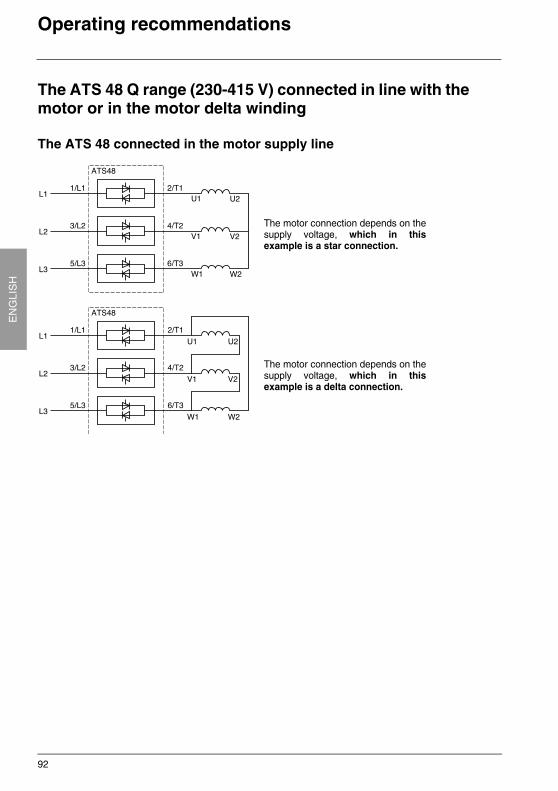
The ATS 48 connected in the motor supply line
The motor connection depends on thesupply voltage, which in thisexample is a star connection.
The motor connection depends on thesupply voltage, which in thisexample is a delta connection.
93
EN
GLIS
HOperating recommendations
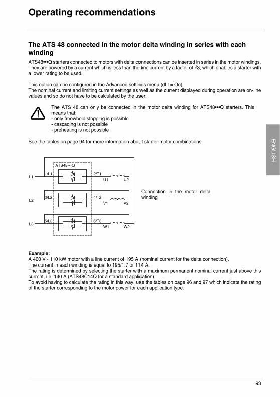
The ATS 48 connected in the motor delta winding in series with each windingATS48•••Q starters connected to motors with delta connections can be inserted in series in the motor windings.They are powered by a current which is less than the line current by a factor of √3, which enables a starter witha lower rating to be used.
This option can be configured in the Advanced settings menu (dLt = On).The nominal current and limiting current settings as well as the current displayed during operation are on-linevalues and so do not have to be calculated by the user.
The ATS 48 can only be connected in the motor delta winding for ATS48•••Q starters. Thismeans that:- only freewheel stopping is possible- cascading is not possible- preheating is not possible
See the tables on page 94 for more information about starter-motor combinations.
Example:A 400 V - 110 kW motor with a line current of 195 A (nominal current for the delta connection).The current in each winding is equal to 195/1.7 or 114 A.The rating is determined by selecting the starter with a maximum permanent nominal current just above thiscurrent, i.e. 140 A (ATS48C14Q for a standard application).To avoid having to calculate the rating in this way, use the tables on page 96 and 97 which indicate the ratingof the starter corresponding to the motor power for each application type.
Connection in the motor deltawinding
94
EN
GLI
SH
Starter-motor combinations
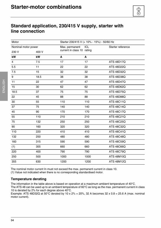
Standard application, 230/415 V supply, starter withline connection
The nominal motor current In must not exceed the max. permanent current in class 10.(1) Value not indicated when there is no corresponding standardised motor.
Temperature deratingThe information in the table above is based on operation at a maximum ambient temperature of 40°C.The ATS 48 can be used up to an ambient temperature of 60°C as long as the max. permanent current in class10 is derated by 2% for each degree above 40°C.Example: ATS 48D32Q at 50°C derated by 10 x 2% = 20%, 32 A becomes 32 x 0.8 = 25.6 A (max. nominalmotor current).
Motor Starter 230/415 V (+ 10% - 15%) - 50/60 Hz
Nominal motor power Max. permanent current in class 10
ICLrating
Starter reference
230 V 400 V
kW kW A A
4 7.5 17 17 ATS 48D17Q
5.5 11 22 22 ATS 48D22Q
7.5 15 32 32 ATS 48D32Q
9 18.5 38 38 ATS 48D38Q
11 22 47 47 ATS 48D47Q
15 30 62 62 ATS 48D62Q
18.5 37 75 75 ATS 48D75Q
22 45 88 88 ATS 48D88Q
30 55 110 110 ATS 48C11Q
37 75 140 140 ATS 48C14Q
45 90 170 170 ATS 48C17Q
55 110 210 210 ATS 48C21Q
75 132 250 250 ATS 48C25Q
90 160 320 320 ATS 48C32Q
110 220 410 410 ATS 48C41Q
132 250 480 480 ATS 48C48Q
160 315 590 590 ATS 48C59Q
(1) 355 660 660 ATS 48C66Q
220 400 790 790 ATS 48C79Q
250 500 1000 1000 ATS 48M10Q
355 630 1200 1200 ATS 48M12Q

95
EN
GLIS
HStarter-motor combinations
Severe application, 230/415 V supply, starter withline connection
The nominal motor current In must not exceed the max. permanent current in class 20.(1) Value not indicated when there is no corresponding standardised motor.
Temperature deratingThe information in the table above is based on operation at a maximum ambient temperature of 40°C.The ATS 48 can be used up to an ambient temperature of 60°C as long as the max. permanent current in class20 is derated by 2% for each degree above 40°C.Example: ATS 48D32Q at 50°C derated by 10 x 2% = 20%, 22 A becomes 22 x 0.8 = 17.6 A (max. nominalmotor current).
Motor Starter 230/415 V (+ 10% - 15%) - 50/60 Hz
Nominal motor power Max. permanent current in class 20
ICLrating
Starter reference
230 V 400 V
kW kW A A
3 5.5 12 17 ATS 48D17Q
4 7.5 17 22 ATS 48D22Q
5.5 11 22 32 ATS 48D32Q
7.5 15 32 38 ATS 48D38Q
9 18.5 38 47 ATS 48D47Q
11 22 47 62 ATS 48D62Q
15 30 62 75 ATS 48D75Q
18.5 37 75 88 ATS 48D88Q
22 45 88 110 ATS 48C11Q
30 55 110 140 ATS 48C14Q
37 75 140 170 ATS 48C17Q
45 90 170 210 ATS 48C21Q
55 110 210 250 ATS 48C25Q
75 132 250 320 ATS 48C32Q
90 160 320 410 ATS 48C41Q
110 220 410 480 ATS 48C48Q
132 250 480 590 ATS 48C59Q
160 315 590 660 ATS 48C66Q
(1) 355 660 790 ATS 48C79Q
220 400 790 1000 ATS 48M10Q
250 500 1000 1200 ATS 48M12Q
96
EN
GLI
SH
Starter-motor combinations
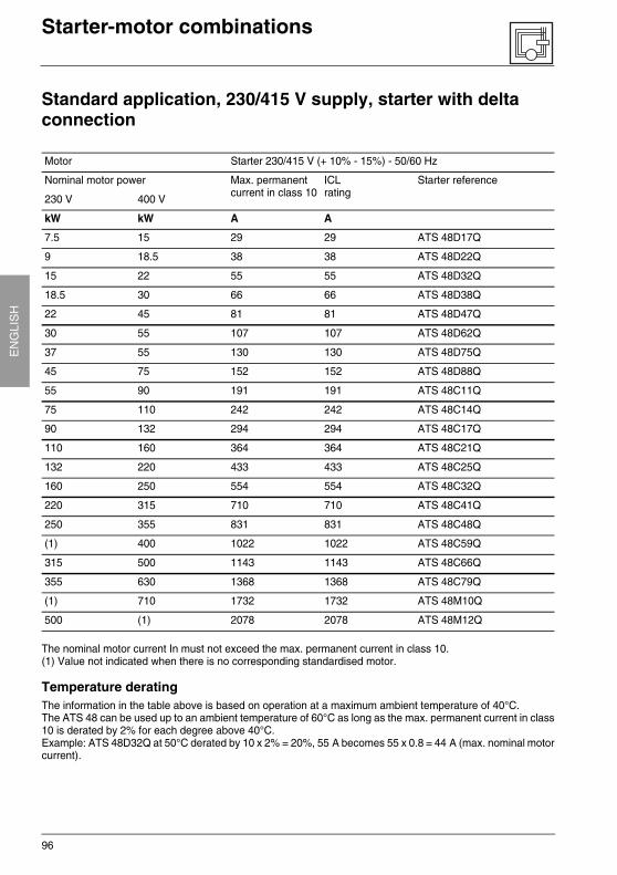
Standard application, 230/415 V supply, starter with delta connection
The nominal motor current In must not exceed the max. permanent current in class 10.(1) Value not indicated when there is no corresponding standardised motor.
Temperature deratingThe information in the table above is based on operation at a maximum ambient temperature of 40°C.The ATS 48 can be used up to an ambient temperature of 60°C as long as the max. permanent current in class10 is derated by 2% for each degree above 40°C.Example: ATS 48D32Q at 50°C derated by 10 x 2% = 20%, 55 A becomes 55 x 0.8 = 44 A (max. nominal motorcurrent).
Motor Starter 230/415 V (+ 10% - 15%) - 50/60 Hz
Nominal motor power Max. permanent current in class 10
ICLrating
Starter reference
230 V 400 V
kW kW A A
7.5 15 29 29 ATS 48D17Q
9 18.5 38 38 ATS 48D22Q
15 22 55 55 ATS 48D32Q
18.5 30 66 66 ATS 48D38Q
22 45 81 81 ATS 48D47Q
30 55 107 107 ATS 48D62Q
37 55 130 130 ATS 48D75Q
45 75 152 152 ATS 48D88Q
55 90 191 191 ATS 48C11Q
75 110 242 242 ATS 48C14Q
90 132 294 294 ATS 48C17Q
110 160 364 364 ATS 48C21Q
132 220 433 433 ATS 48C25Q
160 250 554 554 ATS 48C32Q
220 315 710 710 ATS 48C41Q
250 355 831 831 ATS 48C48Q
(1) 400 1022 1022 ATS 48C59Q
315 500 1143 1143 ATS 48C66Q
355 630 1368 1368 ATS 48C79Q
(1) 710 1732 1732 ATS 48M10Q
500 (1) 2078 2078 ATS 48M12Q
97
EN
GLIS
HStarter-motor combinations
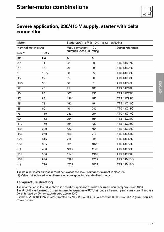
Severe application, 230/415 V supply, starter with delta connection
The nominal motor current In must not exceed the max. permanent current in class 20.(1) Value not indicated when there is no corresponding standardised motor.
Temperature deratingThe information in the table above is based on operation at a maximum ambient temperature of 40°C.The ATS 48 can be used up to an ambient temperature of 60°C as long as the max. permanent current in class20 is derated by 2% for each degree above 40°C.Example: ATS 48D32Q at 50°C derated by 10 x 2% = 20%, 38 A becomes 38 x 0.8 = 30.4 A (max. nominalmotor current).
Motor Starter 230/415 V (+ 10% - 15%) - 50/60 Hz
Nominal motor power Max. permanent current in class 20
ICLrating
Starter reference
230 V 400 V
kW kW A A
5.5 11 22 29 ATS 48D17Q
7.5 15 29 38 ATS 48D22Q
9 18.5 38 55 ATS 48D32Q
15 22 55 66 ATS 48D38Q
18.5 30 66 81 ATS 48D47Q
22 45 81 107 ATS 48D62Q
30 55 107 130 ATS 48D75Q
37 55 130 152 ATS 48D88Q
45 75 152 191 ATS 48C11Q
55 90 191 242 ATS 48C14Q
75 110 242 294 ATS 48C17Q
90 132 294 364 ATS 48C21Q
110 160 364 433 ATS 48C25Q
132 220 433 554 ATS 48C32Q
160 250 554 710 ATS 48C41Q
220 315 710 831 ATS 48C48Q
250 355 831 1022 ATS 48C59Q
(1) 400 1022 1143 ATS 48C66Q
315 500 1143 1368 ATS 48C79Q
355 630 1368 1732 ATS 48M10Q
(1) 710 1732 2078 ATS 48M12Q
98
EN
GLI
SH
Starter-motor combinations
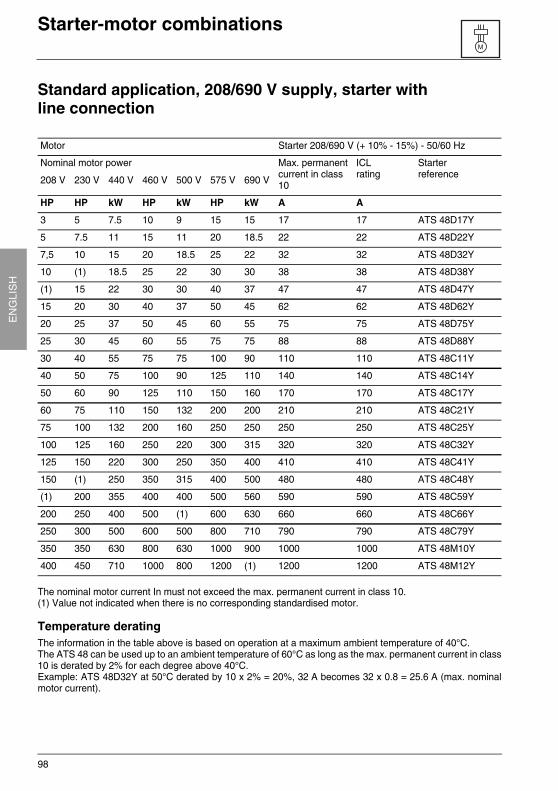
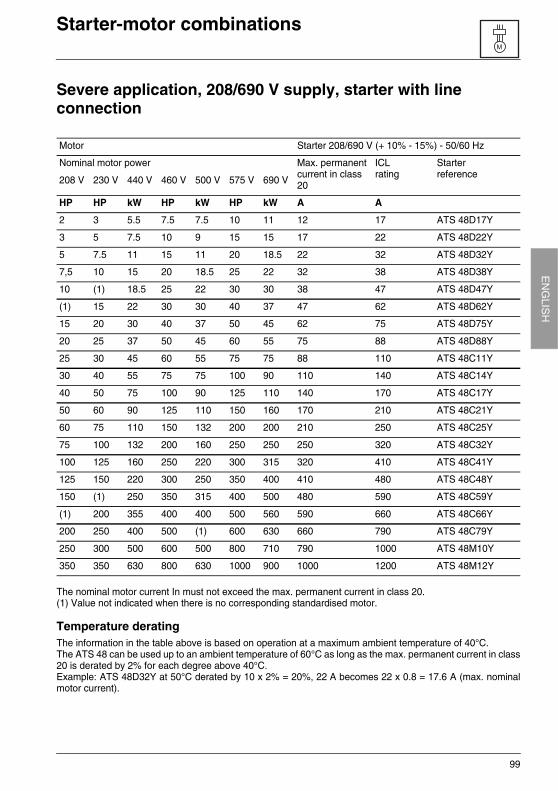
Standard application, 208/690 V supply, starter withline connection
The nominal motor current In must not exceed the max. permanent current in class 10.(1) Value not indicated when there is no corresponding standardised motor.
Temperature deratingThe information in the table above is based on operation at a maximum ambient temperature of 40°C.The ATS 48 can be used up to an ambient temperature of 60°C as long as the max. permanent current in class10 is derated by 2% for each degree above 40°C.Example: ATS 48D32Y at 50°C derated by 10 x 2% = 20%, 32 A becomes 32 x 0.8 = 25.6 A (max. nominalmotor current).
Motor Starter 208/690 V (+ 10% - 15%) - 50/60 Hz
Nominal motor power Max. permanent current in class 10
ICLrating
Starterreference
208 V 230 V 440 V 460 V 500 V 575 V 690 V
HP HP kW HP kW HP kW A A
3 5 7.5 10 9 15 15 17 17 ATS 48D17Y
5 7.5 11 15 11 20 18.5 22 22 ATS 48D22Y
7,5 10 15 20 18.5 25 22 32 32 ATS 48D32Y
10 (1) 18.5 25 22 30 30 38 38 ATS 48D38Y
(1) 15 22 30 30 40 37 47 47 ATS 48D47Y
15 20 30 40 37 50 45 62 62 ATS 48D62Y
20 25 37 50 45 60 55 75 75 ATS 48D75Y
25 30 45 60 55 75 75 88 88 ATS 48D88Y
30 40 55 75 75 100 90 110 110 ATS 48C11Y
40 50 75 100 90 125 110 140 140 ATS 48C14Y
50 60 90 125 110 150 160 170 170 ATS 48C17Y
60 75 110 150 132 200 200 210 210 ATS 48C21Y
75 100 132 200 160 250 250 250 250 ATS 48C25Y
100 125 160 250 220 300 315 320 320 ATS 48C32Y
125 150 220 300 250 350 400 410 410 ATS 48C41Y
150 (1) 250 350 315 400 500 480 480 ATS 48C48Y
(1) 200 355 400 400 500 560 590 590 ATS 48C59Y
200 250 400 500 (1) 600 630 660 660 ATS 48C66Y
250 300 500 600 500 800 710 790 790 ATS 48C79Y
350 350 630 800 630 1000 900 1000 1000 ATS 48M10Y
400 450 710 1000 800 1200 (1) 1200 1200 ATS 48M12Y
99
EN
GLIS
HStarter-motor combinations
Severe application, 208/690 V supply, starter with lineconnection
The nominal motor current In must not exceed the max. permanent current in class 20.(1) Value not indicated when there is no corresponding standardised motor.
Temperature deratingThe information in the table above is based on operation at a maximum ambient temperature of 40°C.The ATS 48 can be used up to an ambient temperature of 60°C as long as the max. permanent current in class20 is derated by 2% for each degree above 40°C.Example: ATS 48D32Y at 50°C derated by 10 x 2% = 20%, 22 A becomes 22 x 0.8 = 17.6 A (max. nominalmotor current).
Motor Starter 208/690 V (+ 10% - 15%) - 50/60 Hz
Nominal motor power Max. permanent current in class 20
ICLrating
Starterreference
208 V 230 V 440 V 460 V 500 V 575 V 690 V
HP HP kW HP kW HP kW A A
2 3 5.5 7.5 7.5 10 11 12 17 ATS 48D17Y
3 5 7.5 10 9 15 15 17 22 ATS 48D22Y
5 7.5 11 15 11 20 18.5 22 32 ATS 48D32Y
7,5 10 15 20 18.5 25 22 32 38 ATS 48D38Y
10 (1) 18.5 25 22 30 30 38 47 ATS 48D47Y
(1) 15 22 30 30 40 37 47 62 ATS 48D62Y
15 20 30 40 37 50 45 62 75 ATS 48D75Y
20 25 37 50 45 60 55 75 88 ATS 48D88Y
25 30 45 60 55 75 75 88 110 ATS 48C11Y
30 40 55 75 75 100 90 110 140 ATS 48C14Y
40 50 75 100 90 125 110 140 170 ATS 48C17Y
50 60 90 125 110 150 160 170 210 ATS 48C21Y
60 75 110 150 132 200 200 210 250 ATS 48C25Y
75 100 132 200 160 250 250 250 320 ATS 48C32Y
100 125 160 250 220 300 315 320 410 ATS 48C41Y
125 150 220 300 250 350 400 410 480 ATS 48C48Y
150 (1) 250 350 315 400 500 480 590 ATS 48C59Y
(1) 200 355 400 400 500 560 590 660 ATS 48C66Y
200 250 400 500 (1) 600 630 660 790 ATS 48C79Y
250 300 500 600 500 800 710 790 1000 ATS 48M10Y
350 350 630 800 630 1000 900 1000 1200 ATS 48M12Y
100
EN
GLI
SH
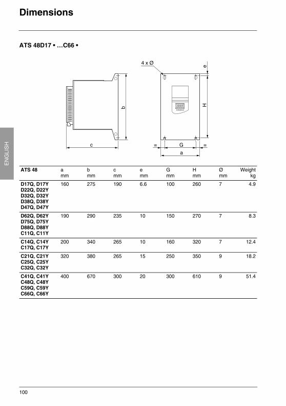
Dimensions
ATS 48D17 • …C66 •
ATS 48 amm
b mm
c mm
emm
G mm
H mm
Ømm
Weightkg
D17Q, D17YD22Q, D22YD32Q, D32YD38Q, D38YD47Q, D47Y
160 275 190 6.6 100 260 7 4.9
D62Q, D62YD75Q, D75YD88Q, D88YC11Q, C11Y
190 290 235 10 150 270 7 8.3
C14Q, C14YC17Q, C17Y
200 340 265 10 160 320 7 12.4
C21Q, C21YC25Q, C25YC32Q, C32Y
320 380 265 15 250 350 9 18.2
C41Q, C41YC48Q, C48YC59Q, C59YC66Q, C66Y
400 670 300 20 300 610 9 51.4
101
EN
GLIS
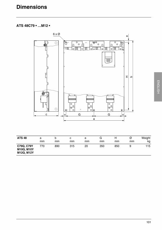
HDimensions
ATS 48C79 • …M12 •
ATS 48 amm
b mm
c mm
emm
G mm
H mm
Ømm
Weightkg
C79Q, C79YM10Q, M10YM12Q, M12Y
770 890 315 20 350 850 9 115
102
EN
GLI
SH
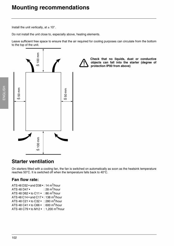
Mounting recommendations
Install the unit vertically, at ± 10°.
Do not install the unit close to, especially above, heating elements.
Leave sufficient free space to ensure that the air required for cooling purposes can circulate from the bottomto the top of the unit.
Check that no liquids, dust or conductiveobjects can fall into the starter (degree ofprotection IP00 from above)
Starter ventilationOn starters fitted with a cooling fan, the fan is switched on automatically as soon as the heatsink temperaturereaches 50°C. It is switched off when the temperature falls back to 40°C.
Fan flow rate:ATS 48 D32 • and D38 • : 14 m3/hourATS 48 D47 • : 28 m3/hourATS 48 D62 • to C11 • : 86 m3/hourATS 48 C14 • and C17 • : 138 m3/hourATS 48 C21 • to C32 • : 280 m3/hourATS 48 C41 • to C66 • : 600 m3/hourATS 48 C79 • to M12 • : 1,200 m3/hour
Š 1
00 m
m
Š 5
0 m
m
Š 5
0 m
m
Š 1
00 m
m
103
EN
GLIS
HMounting in a wall-fixing or floor-standing enclosure
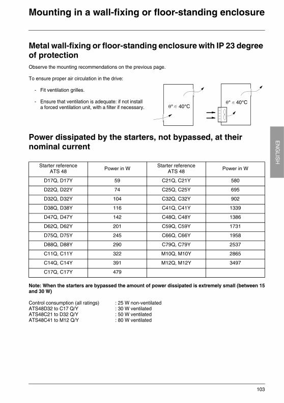
Metal wall-fixing or floor-standing enclosure with IP 23 degree of protectionObserve the mounting recommendations on the previous page.
To ensure proper air circulation in the drive:
- Fit ventilation grilles.
- Ensure that ventilation is adequate: if not install a forced ventilation unit, with a filter if necessary.
Power dissipated by the starters, not bypassed, at their nominal current
Note: When the starters are bypassed the amount of power dissipated is extremely small (between 15and 30 W)
Control consumption (all ratings) : 25 W non-ventilatedATS48D32 to C17 Q/Y : 30 W ventilatedATS48C21 to D32 Q/Y : 50 W ventilatedATS48C41 to M12 Q/Y : 80 W ventilated
Starter referenceATS 48 Power in W Starter reference
ATS 48 Power in W
D17Q, D17Y 59 C21Q, C21Y 580
D22Q, D22Y 74 C25Q, C25Y 695
D32Q, D32Y 104 C32Q, C32Y 902
D38Q, D38Y 116 C41Q, C41Y 1339
D47Q, D47Y 142 C48Q, C48Y 1386
D62Q, D62Y 201 C59Q, C59Y 1731
D75Q, D75Y 245 C66Q, C66Y 1958
D88Q, D88Y 290 C79Q, C79Y 2537
C11Q, C11Y 322 M10Q, M10Y 2865
C14Q, C14Y 391 M12Q, M12Y 3497
C17Q, C17Y 479
104
EN
GLI
SH
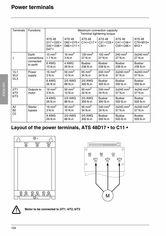
Power terminals
Layout of the power terminals, ATS 48D17 • to C11 •
Motor to be connected to 2/T1, 4/T2, 6/T3
Terminals Functions Maximum connection capacityTerminal tightening torque
ATS 48D17 • D22 •D32 • D38 •D47 •
ATS 48D62 • D75 •D88 • C11 •
ATS 48C14 • C17 •
ATS 48C21 • C25 •C32 •
ATS 48C41 • C48 •C59 • C66 •
ATS 48C79 • M10 • M12 •
sEarth connections connected to earth
10 mm2
1.7 N.m16 mm2
3 N.m120 mm2
27 N.m120 mm2
27 N.m240 mm2
27 N.m2x240 mm2
27 N.m
8 AWG15 lb.in
4 AWG26 lb.in
Busbar238 lb.in
Busbar238 lb.in
Busbar238 lb.in
Busbar238 lb.in
1/L13/L25/L3
Power supply
16 mm2
3 N.m50 mm2
10 N.m95 mm2
34 N.m240 mm2
34 N.m2x240 mm2
57 N.m4x240 mm2
57 N.m
8 AWG26 lb.in
2/0 AWG88 lb.in
2/0 AWG300 lb.in
Busbar300 lb.in
Busbar500 lb.in
Busbar500 lb.in
2/T14/T26/T3
Outputs to motor
16 mm2
3 N.m50 mm2
10 N.m95 mm2
34 N.m240 mm2
34 N.m2x240 mm2
57 N.m4x240 mm2
57 N.m
8 AWG26 lb.in
2/0 AWG88 lb.in
2/0 AWG300 lb.in
Busbar300 lb.in
Busbar500 lb.in
Busbar500 lb.in
A2B2C2
Starter bypass
16 mm2
3 N.m50 mm2
10 N.m95 mm2
34 N.m240 mm2
34 N.m2x240 mm2
57 N.m4x240 mm2
57 N.m
8 AWG26 lb.in
2/0 AWG88 lb.in
2/0 AWG300 lb.in
Busbar300 lb.in
Busbar500 lb.in
Busbar500 lb.in
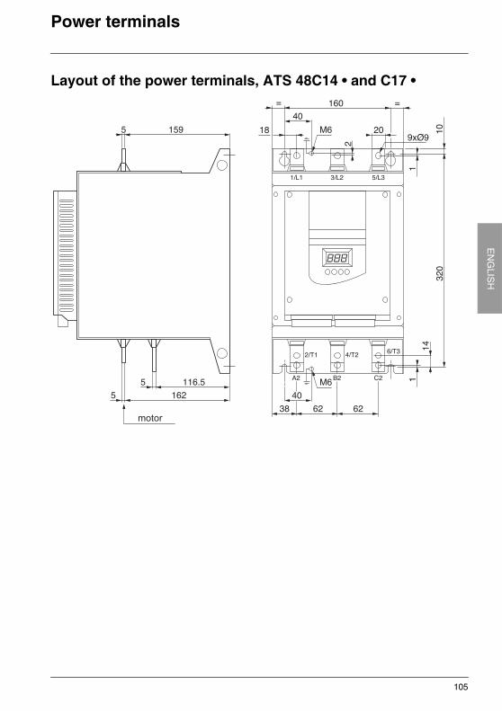
105
EN
GLIS
HPower terminals
Layout of the power terminals, ATS 48C14 • and C17 •
motor
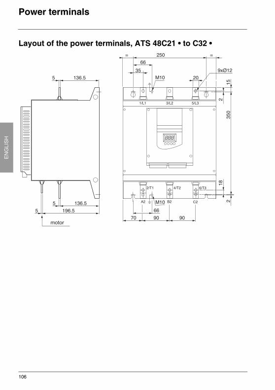
106
EN
GLI
SH
Power terminals
Layout of the power terminals, ATS 48C21 • to C32 •
motor
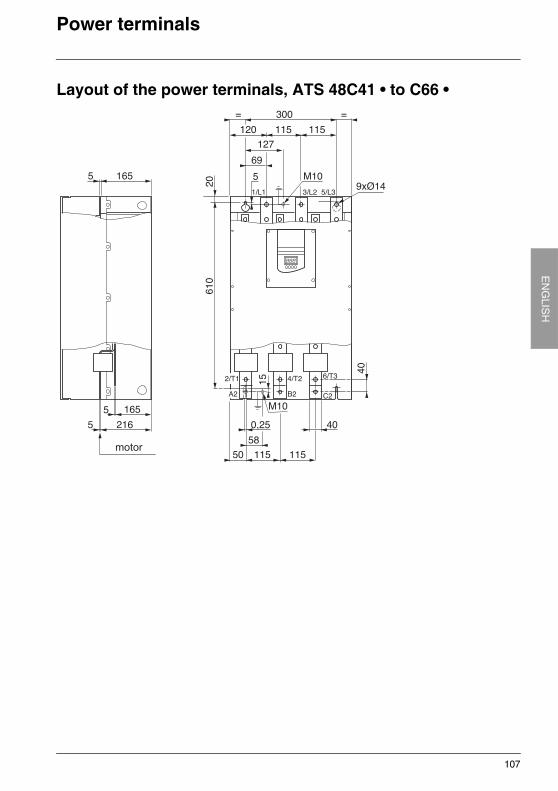
107
EN
GLIS
HPower terminals
Layout of the power terminals, ATS 48C41 • to C66 •
motor
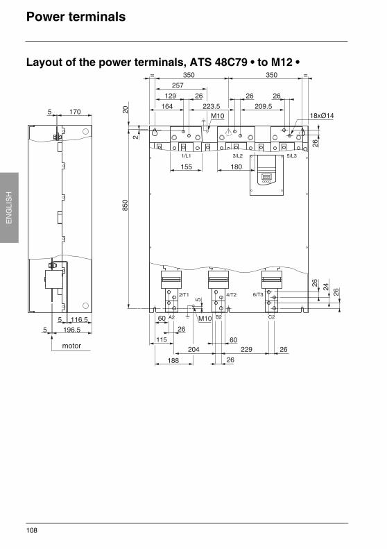
108
EN
GLI
SH
Power terminals
Layout of the power terminals, ATS 48C79 • to M12 •
115motor
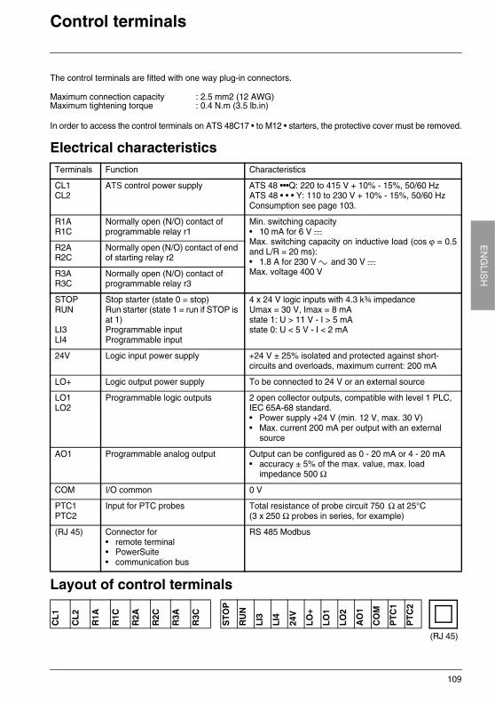
109
EN
GLIS
HControl terminals
The control terminals are fitted with one way plug-in connectors.
In order to access the control terminals on ATS 48C17 • to M12 • starters, the protective cover must be removed.
Electrical characteristics
Layout of control terminals
Maximum connection capacity : 2.5 mm2 (12 AWG)Maximum tightening torque : 0.4 N.m (3.5 lb.in)
Terminals Function Characteristics
CL1CL2
ATS control power supply ATS 48 •••Q: 220 to 415 V + 10% - 15%, 50/60 HzATS 48 • • • Y: 110 to 230 V + 10% - 15%, 50/60 HzConsumption see page 103.
R1AR1C
Normally open (N/O) contact of programmable relay r1
Min. switching capacity• 10 mA for 6 V aMax. switching capacity on inductive load (cos ϕ = 0.5and L/R = 20 ms):• 1.8 A for 230 V c and 30 V aMax. voltage 400 V
R2AR2C
Normally open (N/O) contact of end of starting relay r2
R3AR3C
Normally open (N/O) contact of programmable relay r3
STOPRUN
LI3LI4
Stop starter (state 0 = stop)Run starter (state 1 = run if STOP is at 1)Programmable inputProgrammable input
4 x 24 V logic inputs with 4.3 k¾ impedanceUmax = 30 V, Imax = 8 mAstate 1: U > 11 V - I > 5 mAstate 0: U < 5 V - I < 2 mA
24V Logic input power supply +24 V ± 25% isolated and protected against short-circuits and overloads, maximum current: 200 mA
LO+ Logic output power supply To be connected to 24 V or an external source
LO1LO2
Programmable logic outputs 2 open collector outputs, compatible with level 1 PLC, IEC 65A-68 standard.• Power supply +24 V (min. 12 V, max. 30 V)• Max. current 200 mA per output with an external
source
AO1 Programmable analog output Output can be configured as 0 - 20 mA or 4 - 20 mA• accuracy ± 5% of the max. value, max. load
impedance 500 Ω
COM I/O common 0 V
PTC1PTC2
Input for PTC probes Total resistance of probe circuit 750 Ω at 25°C (3 x 250 Ω probes in series, for example)
(RJ 45) Connector for• remote terminal• PowerSuite• communication bus
RS 485 Modbus
CL1
CL2
R1A
R1C
R2A
R2C
R3A
R3C
STO
P
RU
N
LI3
LI4
24V
LO+
LO1
LO2
AO
1
CO
M
PTC
1
PTC
2
(RJ 45)
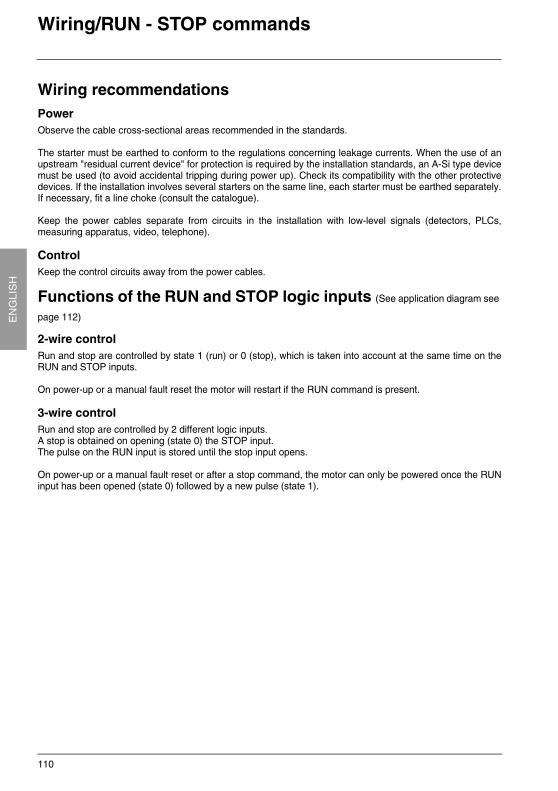
110
EN
GLI
SH
Wiring/RUN - STOP commands
Wiring recommendationsPowerObserve the cable cross-sectional areas recommended in the standards.
The starter must be earthed to conform to the regulations concerning leakage currents. When the use of anupstream "residual current device" for protection is required by the installation standards, an A-Si type devicemust be used (to avoid accidental tripping during power up). Check its compatibility with the other protectivedevices. If the installation involves several starters on the same line, each starter must be earthed separately.If necessary, fit a line choke (consult the catalogue).
Keep the power cables separate from circuits in the installation with low-level signals (detectors, PLCs,measuring apparatus, video, telephone).
ControlKeep the control circuits away from the power cables.
Functions of the RUN and STOP logic inputs (See application diagram see
page 112)
2-wire controlRun and stop are controlled by state 1 (run) or 0 (stop), which is taken into account at the same time on theRUN and STOP inputs.
On power-up or a manual fault reset the motor will restart if the RUN command is present.
3-wire controlRun and stop are controlled by 2 different logic inputs.A stop is obtained on opening (state 0) the STOP input.The pulse on the RUN input is stored until the stop input opens.
On power-up or a manual fault reset or after a stop command, the motor can only be powered once the RUNinput has been opened (state 0) followed by a new pulse (state 1).
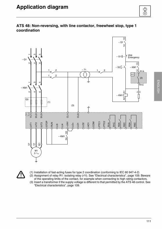
111
EN
GLIS
HApplication diagram
ATS 48: Non-reversing, with line contactor, freewheel stop, type 1 coordination
(1) Installation of fast-acting fuses for type 2 coordination (conforming to IEC 60 947-4-2)(2) Assignment of relay R1: isolating relay (r1I). See “Electrical characteristics”, page 109. Beware
of the operating limits of the contact, for example when connecting to high rating contactors.(3) Insert a transformer if the supply voltage is different to that permitted by the ATS 48 control. See
“Electrical characteristics”, page 109.
stopEmergency
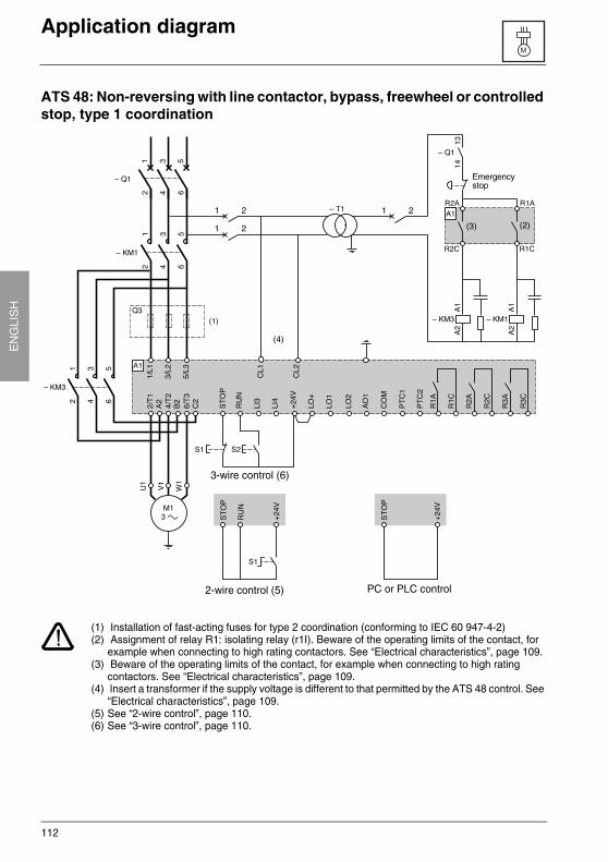
112
EN
GLI
SH
Application diagram
ATS 48: Non-reversing with line contactor, bypass, freewheel or controlled stop, type 1 coordination
(1) Installation of fast-acting fuses for type 2 coordination (conforming to IEC 60 947-4-2)(2) Assignment of relay R1: isolating relay (r1I). Beware of the operating limits of the contact, for
example when connecting to high rating contactors. See “Electrical characteristics”, page 109.(3) Beware of the operating limits of the contact, for example when connecting to high rating
contactors. See “Electrical characteristics”, page 109.(4) Insert a transformer if the supply voltage is different to that permitted by the ATS 48 control. See
“Electrical characteristics”, page 109.(5) See “2-wire control”, page 110.(6) See “3-wire control”, page 110.
Emergencystop
3-wire control (6)
2-wire control (5) PC or PLC control
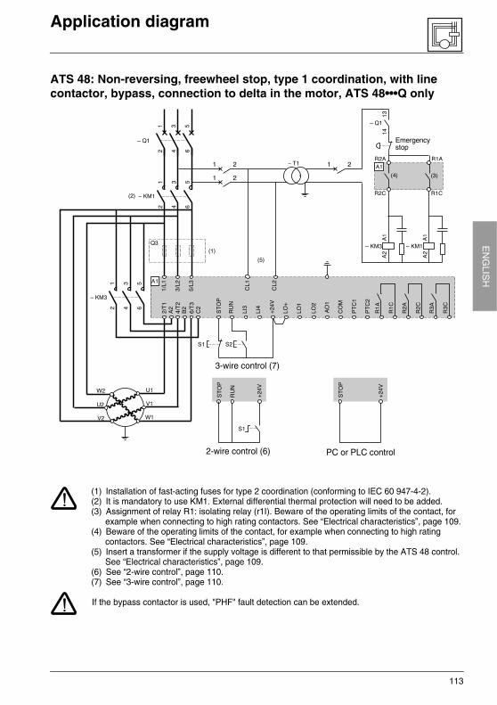
113
EN
GLIS
HApplication diagram
ATS 48: Non-reversing, freewheel stop, type 1 coordination, with line contactor, bypass, connection to delta in the motor, ATS 48•••Q only
(1) Installation of fast-acting fuses for type 2 coordination (conforming to IEC 60 947-4-2).(2) It is mandatory to use KM1. External differential thermal protection will need to be added.(3) Assignment of relay R1: isolating relay (r1I). Beware of the operating limits of the contact, for
example when connecting to high rating contactors. See “Electrical characteristics”, page 109.(4) Beware of the operating limits of the contact, for example when connecting to high rating
contactors. See “Electrical characteristics”, page 109.(5) Insert a transformer if the supply voltage is different to that permissible by the ATS 48 control.
See “Electrical characteristics”, page 109.(6) See “2-wire control”, page 110.(7) See “3-wire control”, page 110.
If the bypass contactor is used, "PHF" fault detection can be extended.
2-wire control (6) PC or PLC control
3-wire control (7)
Emergencystop
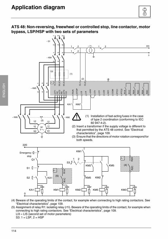
114
EN
GLI
SH
Application diagram
ATS 48: Non-reversing, freewheel or controlled stop, line contactor, motor bypass, LSP/HSP with two sets of parameters
(4) Beware of the operating limits of the contact, for example when connecting to high rating contactors. See “Electrical characteristics”, page 109.
(5) Assignment of relay R1: isolating relay (r1I). Beware of the operating limits of the contact, for example when connecting to high rating contactors. See “Electrical characteristics”, page 109.LI3 = LIS (second set of motor parameters)S3: 1 = LSP, 2 = HSP
(1) Installation of fast-acting fuses in the case of type 2 coordination (conforming to IEC 60 947-4-2).
(2) Insert a transformer if the supply voltage is different to that permitted by the ATS 48 control. See “Electrical characteristics”, page 109.
(3) Ensure that the directions of motor rotation correspond for both speeds.
Emergencystop
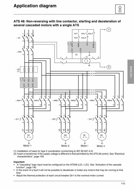
115
EN
GLIS
HApplication diagram
ATS 48: Non-reversing with line contactor, starting and deceleration of several cascaded motors with a single ATS
(1) Installation of fuses for type 2 coordination (conforming to IEC 60 947-4-2)(2) Insert a transformer if the supply voltage is different to that permitted by the ATS 48 control. See “Electrical
characteristics”, page 109.
Important:• A "cascading" logic input must be configured on the ATS48 (LI3 = LIC). See “Activation of the cascade
function”, page 140.• In the event of a fault it will not be possible to decelerate or brake any motors that may be running at that
time.• Adjust the thermal protection of each circuit breaker Qn1 to the nominal motor current.
Motor 2 Motor nMotor iMotor 1
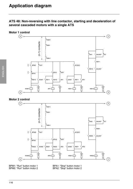
116
EN
GLI
SH
Application diagram
ATS 48: Non-reversing with line contactor, starting and deceleration of several cascaded motors with a single ATS
Motor 1 control
Motor 2 control
BPM1: "Run" button motor 1 BPA1: "Stop" button motor 1BPM2: "Run" button motor 2 BPA2: "Stop" button motor 2
(n-1
) co
ntac
ts(n
-1)
cont
acts
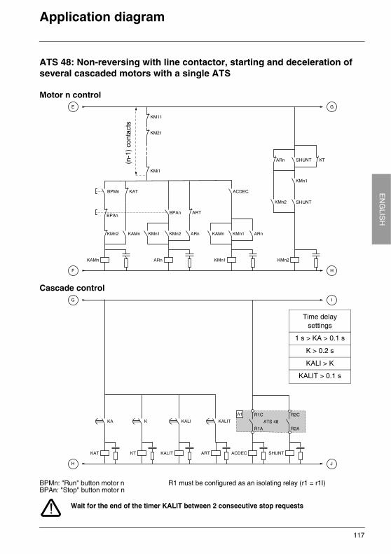
117
EN
GLIS
HApplication diagram
ATS 48: Non-reversing with line contactor, starting and deceleration of several cascaded motors with a single ATS
Motor n control
Cascade control
Wait for the end of the timer KALIT between 2 consecutive stop requests
BPMn: "Run" button motor n R1 must be configured as an isolating relay (r1 = r1I)BPAn: "Stop" button motor n
(n-1
) co
ntac
ts
Time delaysettings
1 s > KA > 0.1 s
K > 0.2 s
KALI > K
KALIT > 0.1 s
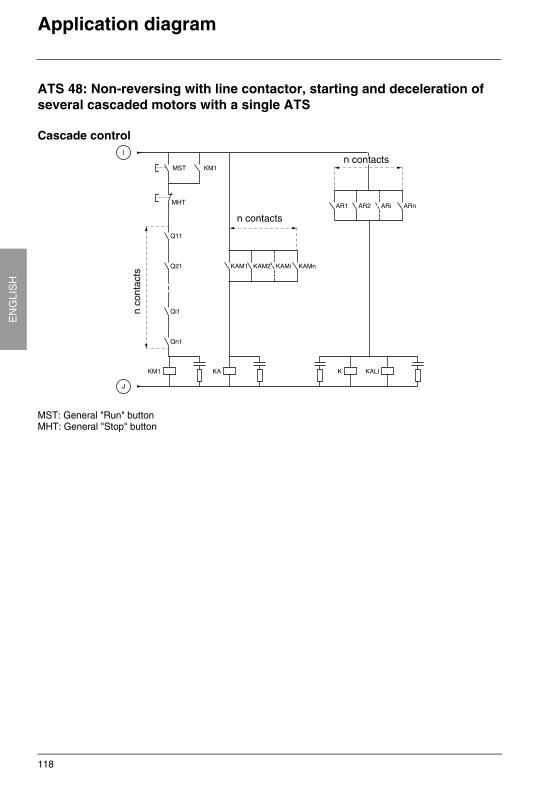
118
EN
GLI
SH
Application diagram
ATS 48: Non-reversing with line contactor, starting and deceleration of several cascaded motors with a single ATS
Cascade control
MST: General "Run" buttonMHT: General "Stop" button
n co
ntac
ts
n contacts
n contacts
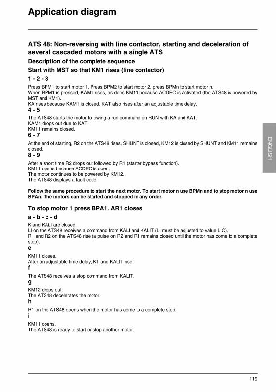
119
EN
GLIS
HApplication diagram
ATS 48: Non-reversing with line contactor, starting and deceleration of several cascaded motors with a single ATSDescription of the complete sequenceStart with MST so that KM1 rises (line contactor)1 - 2 - 3Press BPM1 to start motor 1. Press BPM2 to start motor 2, press BPMn to start motor n.When BPM1 is pressed, KAM1 rises, as does KM11 because ACDEC is activated (the ATS48 is powered byMST and KM1).KA rises because KAM1 is closed. KAT also rises after an adjustable time delay.4 - 5The ATS48 starts the motor following a run command on RUN with KA and KAT.KAM1 drops out due to KAT.KM11 remains closed.6 - 7At the end of starting, R2 on the ATS48 rises, SHUNT is closed, KM12 is closed by SHUNT and KM11 remainsclosed.8 - 9After a short time R2 drops out followed by R1 (starter bypass function).KM11 opens because ACDEC is open.The motor continues to be powered by KM12.The ATS48 displays a fault code.
Follow the same procedure to start the next motor. To start motor n use BPMn and to stop motor n useBPAn. The motors can be started and stopped in any order.
To stop motor 1 press BPA1. AR1 closesa - b - c - dK and KALI are closed.LI on the ATS48 receives a command from KALI and KALIT (LI must be adjusted to value LIC).R1 and R2 on the ATS48 rise (a pulse on R2 and R1 remains closed until the motor has come to a completestop).eKM11 closes.After an adjustable time delay, KT and KALIT rise.fThe ATS48 receives a stop command from KALIT.gKM12 drops out.The ATS48 decelerates the motor.h R1 on the ATS48 opens when the motor has come to a complete stop.iKM11 opens.The ATS48 is ready to start or stop another motor.

120
EN
GLI
SH
Application diagram
ATS 48: Non-reversing with line contactor, starting and deceleration of several cascaded motors with a single ATSTrend diagram
Motor powered by the ATS48
LI3
STOP
RUN
RI(Isolating relay)
KM11
Speed
R2(Control of the
starter bypass contactor)
KM12
Motor start Motor stop
ATS48 idle
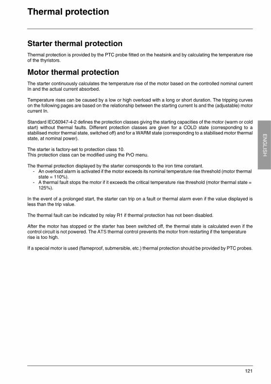
121
EN
GLIS
HThermal protection
Starter thermal protectionThermal protection is provided by the PTC probe fitted on the heatsink and by calculating the temperature riseof the thyristors.
Motor thermal protectionThe starter continuously calculates the temperature rise of the motor based on the controlled nominal currentIn and the actual current absorbed.
Temperature rises can be caused by a low or high overload with a long or short duration. The tripping curveson the following pages are based on the relationship between the starting current Is and the (adjustable) motorcurrent In.
Standard IEC60947-4-2 defines the protection classes giving the starting capacities of the motor (warm or coldstart) without thermal faults. Different protection classes are given for a COLD state (corresponding to astabilised motor thermal state, switched off) and for a WARM state (corresponding to a stabilised motor thermalstate, at nominal power).
The starter is factory-set to protection class 10.This protection class can be modified using the PrO menu.
The thermal protection displayed by the starter corresponds to the iron time constant.- An overload alarm is activated if the motor exceeds its nominal temperature rise threshold (motor thermal
state = 110%).- A thermal fault stops the motor if it exceeds the critical temperature rise threshold (motor thermal state =
125%).
In the event of a prolonged start, the starter can trip on a fault or thermal alarm even if the value displayed isless than the trip value.
The thermal fault can be indicated by relay R1 if thermal protection has not been disabled.
After the motor has stopped or the starter has been switched off, the thermal state is calculated even if thecontrol circuit is not powered. The ATS thermal control prevents the motor from restarting if the temperaturerise is too high.
If a special motor is used (flameproof, submersible, etc.) thermal protection should be provided by PTC probes.
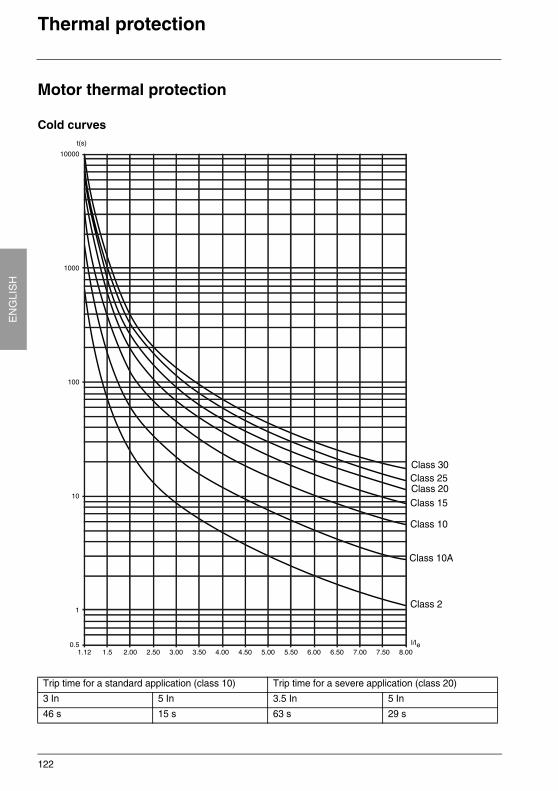
122
EN
GLI
SH
Thermal protection
Motor thermal protection
Cold curves
Trip time for a standard application (class 10) Trip time for a severe application (class 20)
3 In 5 In 3.5 In 5 In
46 s 15 s 63 s 29 s
Class 30
Class 10A
Class 2
Class 20Class 15
Class 10
Class 25
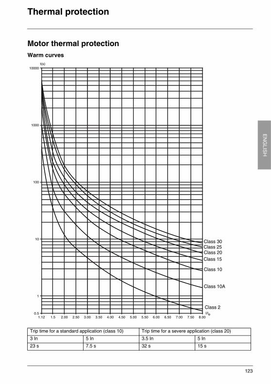
123
EN
GLIS
HThermal protection
Motor thermal protectionWarm curves
Trip time for a standard application (class 10) Trip time for a severe application (class 20)
3 In 5 In 3.5 In 5 In
23 s 7.5 s 32 s 15 s
Class 30Class 25Class 20Class 15
Class 10
Class 10A
Class 2
124
EN
GLI
SH
Thermal protection
Motor thermal protection with PTC probesPTC probes integrated in the motor to measure its temperature can be connected to the control card terminals.This analog value is managed by the starter.
The "PTC probe thermal overshoot" value can be processed and used in two ways: - stop in the event of a fault if the signal is active- activate an alarm if the signal is active. This alarm can be displayed in a starter status word (serial link)
or on a configurable logic output.
Note:PTC probe protection does not deactivate the motor thermal protection provided by the calculation. Both typesof protection can operate in parallel.
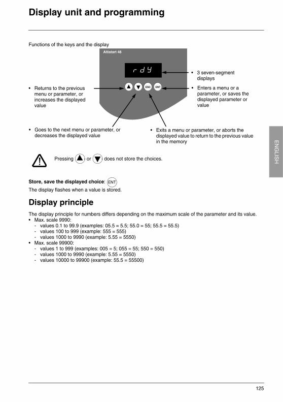
125
EN
GLIS
HDisplay unit and programming
Functions of the keys and the display
Pressing or does not store the choices.
Store, save the displayed choice:
The display flashes when a value is stored.
Display principleThe display principle for numbers differs depending on the maximum scale of the parameter and its value.• Max. scale 9990:
- values 0.1 to 99.9 (examples: 05.5 = 5.5; 55.0 = 55; 55.5 = 55.5)- values 100 to 999 (example: 555 = 555) - values 1000 to 9990 (example: 5.55 = 5550)
• Max. scale 99900:- values 1 to 999 (examples: 005 = 5; 055 = 55; 550 = 550)- values 1000 to 9990 (example: 5.55 = 5550)- values 10000 to 99900 (example: 55.5 = 55500)
• 3 seven-segment displays
• Enters a menu or a parameter, or saves the displayed parameter or value
• Returns to the previous menu or parameter, or increases the displayed value
• Exits a menu or parameter, or aborts the displayed value to return to the previous value in the memory
• Goes to the next menu or parameter, or decreases the displayed value
ENT
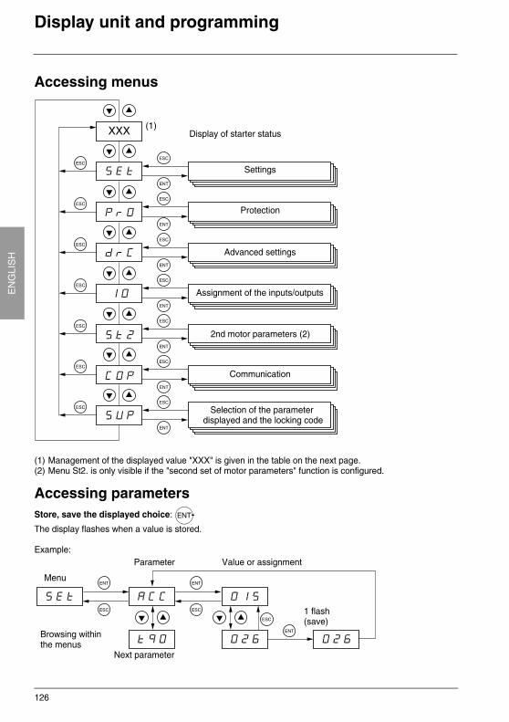
126
EN
GLI
SH
Display unit and programming
Accessing menus
(1) Management of the displayed value "XXX" is given in the table on the next page.(2) Menu St2. is only visible if the "second set of motor parameters" function is configured.
Accessing parametersStore, save the displayed choice:
The display flashes when a value is stored.
Example:
Settings
Protection
Advanced settings
Assignment of the inputs/outputs
2nd motor parameters (2)
Communication
Display of starter status
Selection of the parameter displayed and the locking code
ENT
Menu
Parameter Value or assignment
Next parameter
1 flash(save)
Browsing withinthe menus
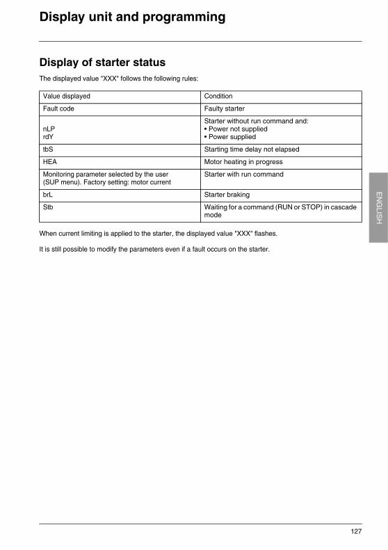
127
EN
GLIS
HDisplay unit and programming
Display of starter statusThe displayed value "XXX" follows the following rules:
When current limiting is applied to the starter, the displayed value "XXX" flashes.
It is still possible to modify the parameters even if a fault occurs on the starter.
Value displayed Condition
Fault code Faulty starter
nLPrdY
Starter without run command and:• Power not supplied• Power supplied
tbS Starting time delay not elapsed
HEA Motor heating in progress
Monitoring parameter selected by the user(SUP menu). Factory setting: motor current
Starter with run command
brL Starter braking
Stb Waiting for a command (RUN or STOP) in cascade mode
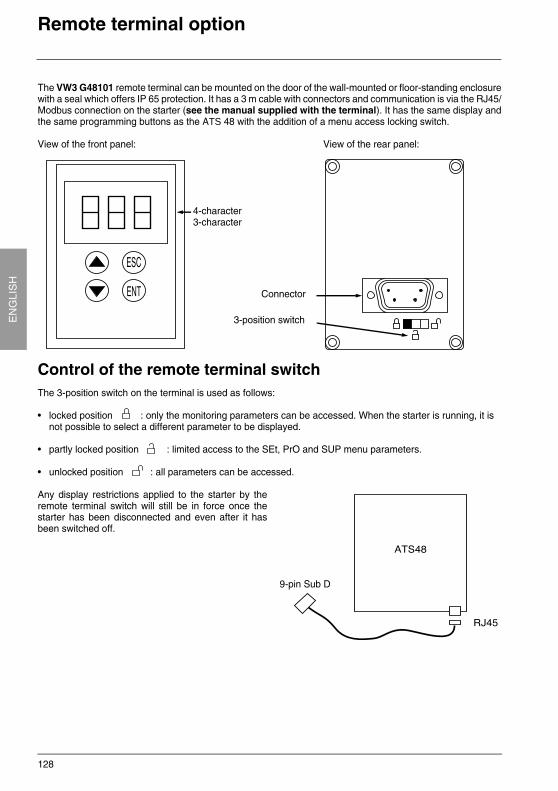
128
EN
GLI
SH
Remote terminal option
The VW3 G48101 remote terminal can be mounted on the door of the wall-mounted or floor-standing enclosurewith a seal which offers IP 65 protection. It has a 3 m cable with connectors and communication is via the RJ45/Modbus connection on the starter (see the manual supplied with the terminal). It has the same display andthe same programming buttons as the ATS 48 with the addition of a menu access locking switch.
View of the front panel: View of the rear panel:
Control of the remote terminal switchThe 3-position switch on the terminal is used as follows:
• locked position : only the monitoring parameters can be accessed. When the starter is running, it is not possible to select a different parameter to be displayed.
• partly locked position : limited access to the SEt, PrO and SUP menu parameters.
• unlocked position : all parameters can be accessed.
Any display restrictions applied to the starter by theremote terminal switch will still be in force once thestarter has been disconnected and even after it hasbeen switched off.
4-character 3-character
Connector
3-position switch
9-pin Sub D
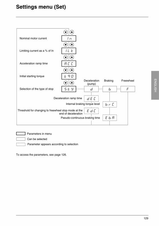
129
EN
GLIS
HSettings menu (Set)
To access the parameters, see page 126.
Nominal motor current
Limiting current as a % of In
Initial starting torque
Acceleration ramp time
Selection of the type of stop
Deceleration(pump)
Braking Freewheel
Deceleration ramp time
Parameters in menu
Can be selected
Parameter appears according to selection
Threshold for changing to freewheel stop mode at theend of deceleration
Internal braking torque level
Pseudo-continuous braking time
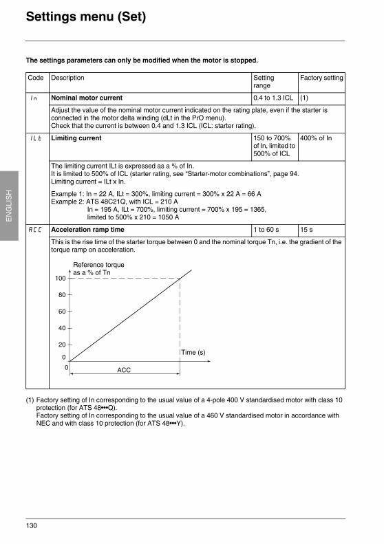
130
EN
GLI
SH
Settings menu (Set)
The settings parameters can only be modified when the motor is stopped.
(1) Factory setting of In corresponding to the usual value of a 4-pole 400 V standardised motor with class 10 protection (for ATS 48•••Q).Factory setting of In corresponding to the usual value of a 460 V standardised motor in accordance with NEC and with class 10 protection (for ATS 48•••Y).
Code Description Settingrange
Factory setting
In Nominal motor current 0.4 to 1.3 ICL (1)
Adjust the value of the nominal motor current indicated on the rating plate, even if the starter is connected in the motor delta winding (dLt in the PrO menu).Check that the current is between 0.4 and 1.3 ICL (ICL: starter rating).
ILt Limiting current 150 to 700% of In, limited to 500% of ICL
400% of In
The limiting current ILt is expressed as a % of In. It is limited to 500% of ICL (starter rating, see “Starter-motor combinations”, page 94.Limiting current = ILt x In.
Example 1: In = 22 A, ILt = 300%, limiting current = 300% x 22 A = 66 AExample 2: ATS 48C21Q, with ICL = 210 A
In = 195 A, ILt = 700%, limiting current = 700% x 195 = 1365, limited to 500% x 210 = 1050 A
ACC Acceleration ramp time 1 to 60 s 15 s
This is the rise time of the starter torque between 0 and the nominal torque Tn, i.e. the gradient of the torque ramp on acceleration.
Time (s)
Reference torqueas a % of Tn
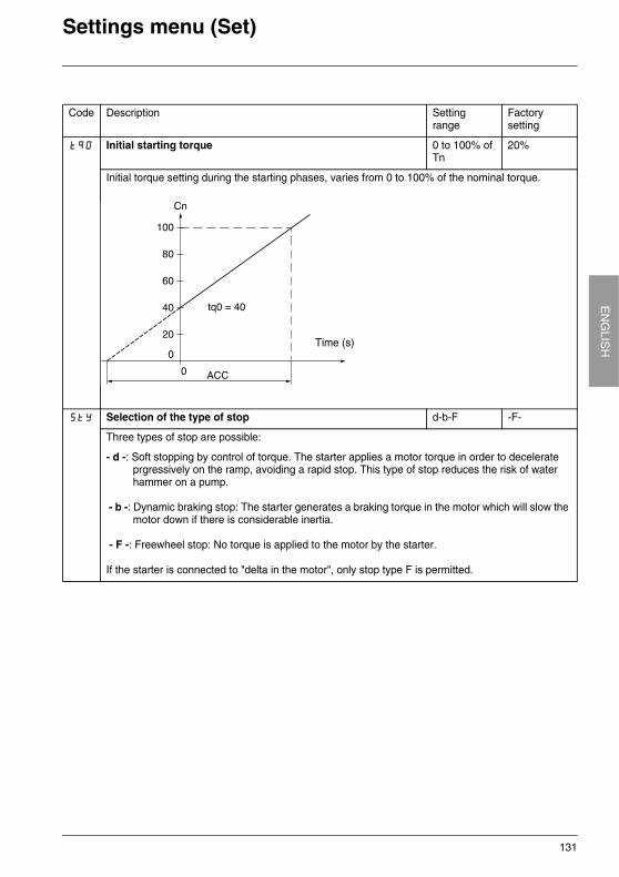
131
EN
GLIS
HSettings menu (Set)
Code Description Settingrange
Factory setting
tq0 Initial starting torque 0 to 100% of Tn
20%
Initial torque setting during the starting phases, varies from 0 to 100% of the nominal torque.
StY Selection of the type of stop d-b-F -F-
Three types of stop are possible:
- d -: Soft stopping by control of torque. The starter applies a motor torque in order to decelerate prgressively on the ramp, avoiding a rapid stop. This type of stop reduces the risk of water hammer on a pump.
- b -: Dynamic braking stop: The starter generates a braking torque in the motor which will slow the motor down if there is considerable inertia.
- F -: Freewheel stop: No torque is applied to the motor by the starter.
If the starter is connected to "delta in the motor", only stop type F is permitted.
Time (s)
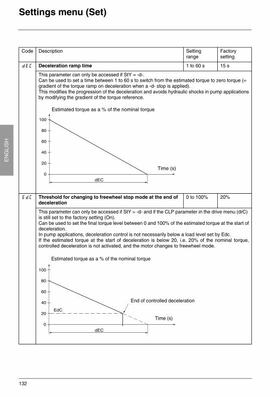
132
EN
GLI
SH
Settings menu (Set)
Code Description Settingrange
Factory setting
dEC Deceleration ramp time 1 to 60 s 15 s
This parameter can only be accessed if StY = -d-.Can be used to set a time between 1 to 60 s to switch from the estimated torque to zero torque (= gradient of the torque ramp on deceleration when a -d- stop is applied).This modifies the progression of the deceleration and avoids hydraulic shocks in pump applicationsby modifying the gradient of the torque reference.
EdC Threshold for changing to freewheel stop mode at the end of deceleration
0 to 100% 20%
This parameter can only be accessed if StY = -d- and if the CLP parameter in the drive menu (drC) is still set to the factory setting (On).Can be used to set the final torque level between 0 and 100% of the estimated torque at the start ofdeceleration.In pump applications, deceleration control is not necessarily below a load level set by Edc.If the estimated torque at the start of deceleration is below 20, i.e. 20% of the nominal torque,controlled deceleration is not activated, and the motor changes to freewheel mode.
Time (s)
Estimated torque as a % of the nominal torque
Time (s)
Estimated torque as a % of the nominal torque
End of controlled deceleration
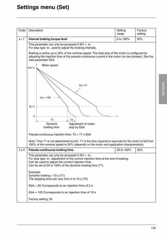
133
EN
GLIS
HSettings menu (Set)
Code Description Settingrange
Factory setting
brC Internal braking torque level 0 to 100% 50%
This parameter can only be accessed if StY = -b-.For stop type -b-, used to adjust the braking intensity.
Braking is active up to 20% of the nominal speed. The total stop of the motor is configured by adjusting the injection time of the pseudo-continuous current in the motor (on two phases). See the next parameter EbA.
Pseudo-continuous injection time: T2 = T1 x EbA
Note: Time T1 is not determined by brC. T1 is the time required in seconds for the motor to fall from 100% of the nominal speed to 20% (depends on the motor and application characteristics).
EbA Pseudo-continuous braking time 20 to 100% 20%
This parameter can only be accessed if StY = -b-.For stop type -b-, adjustment of the current injection time at the end of braking.Can be used to adjust the current injection time.Can be set at 20 to 100% of the dynamic braking time (T1).
Example:Dynamic braking = 10 s (T1)The stopping time can vary from 2 to 10 s (T2)
EbA = 20 Corresponds to an injection time of 2 s
EbA = 100 Corresponds to an injection time of 10 s
Factory setting: 20
Motor speed
Dynamic braking time
Adjustment of motorstop by EbA
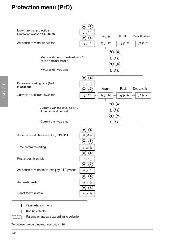
134
EN
GLI
SH
Protection menu (PrO)
To access the parameters, see page 126.
Activation of motor underload
Motor thermal protection Protection classes 10, 20, etc.
Alarm Fault Deactivation
Parameters in menu
Can be selected
Parameter appears according to selection
Motor underload time
Excessive starting time (fault)in seconds
Activation of current overload
Alarm Fault Deactivation
Current overload time
Acceptance of phase rotation, 123, 321
Time before restarting
Phase loss threshold
Activation of motor monitoring by PTC probes
Automatic restart
Reset thermal state
Motor underload threshold as a %of the nominal torque
Current overload level as a %of the nominal current
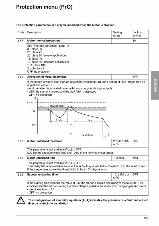
135
EN
GLIS
HProtection menu (PrO)
The protection parameters can only be modified when the motor is stopped.
The configuration of a monitoring alarm (ALA) indicates the presence of a fault but will notdirectly protect the installation
Code Description Settingrange
Factory setting
tHP Motor thermal protection 10
See “Thermal protection”, page 121.30: class 3025: class 2520: class 20 (severe application)15: class 1510: class 10 (standard application)10A: class 10A2: sub-class 2OFF: no protection
ULL Activation of motor underload OFF
If the motor torque is less than an adjustable threshold LUL for a period of time longer than an adjustable value tUL:- ALA: an alarm is activated (internal bit and configurable logic output)- dEF: the starter is locked and the ULF fault is displayed- OFF: no protection
LUL Motor underload threshold 20% to 100% of Tn
60%
This parameter is not available if ULL = OFF.LUL can be set at between 20% and 100% of the nominal motor torque.
tUL Motor underload time 1 to 60 s 60 s
This parameter is not available if ULL = OFF.Time delay tUL is activated as soon as the motor torque falls below threshold LUL. It is reset to zero if the torque rises above this threshold LUL by + 10% (hysteresis).
tLS Excessive starting time 10 to 999 s or OFF
OFF
If the starting time exceeds the value of tLS, the starter is locked and displays the fault StF. The conditions for the end of starting are: line voltage applied to the motor (min. firing angle) and motor current less than 1.3 In.- OFF: no protection
(hysteresis)
detection
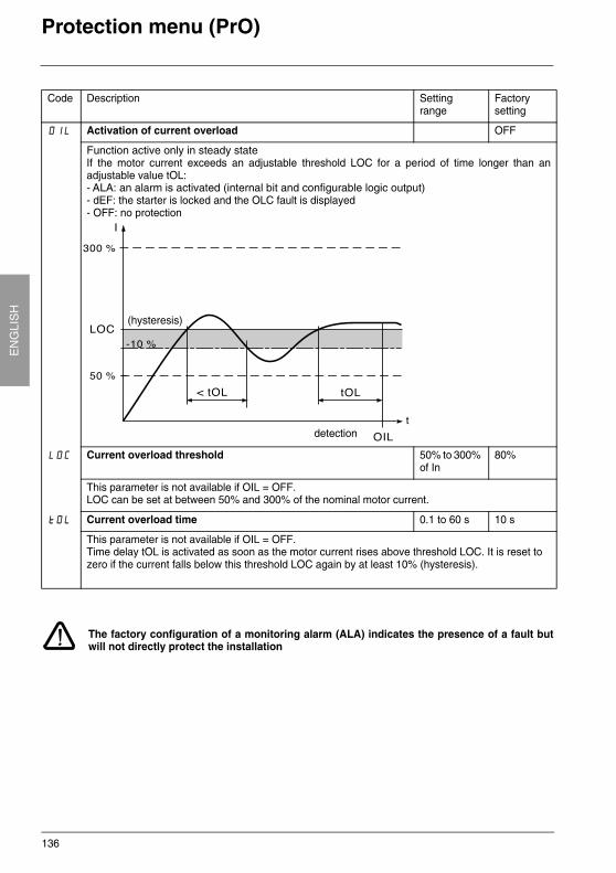
136
EN
GLI
SH
Protection menu (PrO)
The factory configuration of a monitoring alarm (ALA) indicates the presence of a fault butwill not directly protect the installation
Code Description Settingrange
Factory setting
OIL Activation of current overload OFF
Function active only in steady stateIf the motor current exceeds an adjustable threshold LOC for a period of time longer than anadjustable value tOL:- ALA: an alarm is activated (internal bit and configurable logic output)- dEF: the starter is locked and the OLC fault is displayed- OFF: no protection
LOC Current overload threshold 50% to 300% of In
80%
This parameter is not available if OIL = OFF.LOC can be set at between 50% and 300% of the nominal motor current.
tOL Current overload time 0.1 to 60 s 10 s
This parameter is not available if OIL = OFF.Time delay tOL is activated as soon as the motor current rises above threshold LOC. It is reset to zero if the current falls below this threshold LOC again by at least 10% (hysteresis).
(hysteresis)
detection
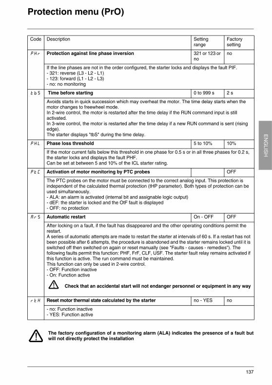
137
EN
GLIS
HProtection menu (PrO)
The factory configuration of a monitoring alarm (ALA) indicates the presence of a fault butwill not directly protect the installation
Code Description Settingrange
Factory setting
PHr Protection against line phase inversion 321 or 123 or no
no
If the line phases are not in the order configured, the starter locks and displays the fault PIF.- 321: reverse (L3 - L2 - L1)- 123: forward (L1 - L2 - L3)- no: no monitoring
tbS Time before starting 0 to 999 s 2 s
Avoids starts in quick succession which may overheat the motor. The time delay starts when the motor changes to freewheel mode.In 2-wire control, the motor is restarted after the time delay if the RUN command input is still activated.In 3-wire control, the motor is restarted after the time delay if a new RUN command is sent (rising edge).The starter displays "tbS" during the time delay.
PHL Phase loss threshold 5 to 10% 10%
If the motor current falls below this threshold in one phase for 0.5 s or in all three phases for 0.2 s, the starter locks and displays the fault PHF.Can be set at between 5 and 10% of the ICL starter rating.
PtC Activation of motor monitoring by PTC probes OFF
The PTC probes on the motor must be connected to the correct analog input. This protection is independent of the calculated thermal protection (tHP parameter). Both types of protection can be used simultaneously.- ALA: an alarm is activated (internal bit and assignable logic output)- dEF: the starter is locked and the OtF fault is displayed- OFF: no protection
ArS Automatic restart On - OFF OFF
After locking on a fault, if the fault has disappeared and the other operating conditions permit the restart.A series of automatic attempts are made to restart the starter at intervals of 60 s. If a restart has not been possible after 6 attempts, the procedure is abandoned and the starter remains locked until it is switched off then switched on again or reset manually (see "Faults - causes - remedies"). The following faults permit this function: PHF, FrF, CLF, USF. The starter fault relay remains activated if this function is active. The run command must be maintained.This function can only be used in 2-wire control.- OFF: Function inactive- On: Function active
Check that an accidental start will not endanger personnel or equipment in any way
rtH Reset motor thermal state calculated by the starter no - YES no
- no: Function inactive- YES: Function active
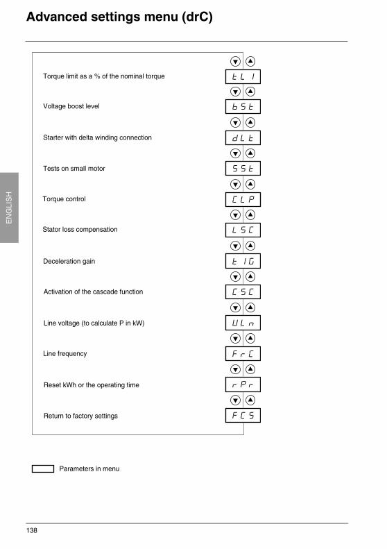
138
EN
GLI
SH
Advanced settings menu (drC)
Parameters in menu
Torque limit as a % of the nominal torque
Voltage boost level
Starter with delta winding connection
Tests on small motor
Torque control
Stator loss compensation
Deceleration gain
Activation of the cascade function
Line voltage (to calculate P in kW)
Line frequency
Reset kWh or the operating time
Return to factory settings
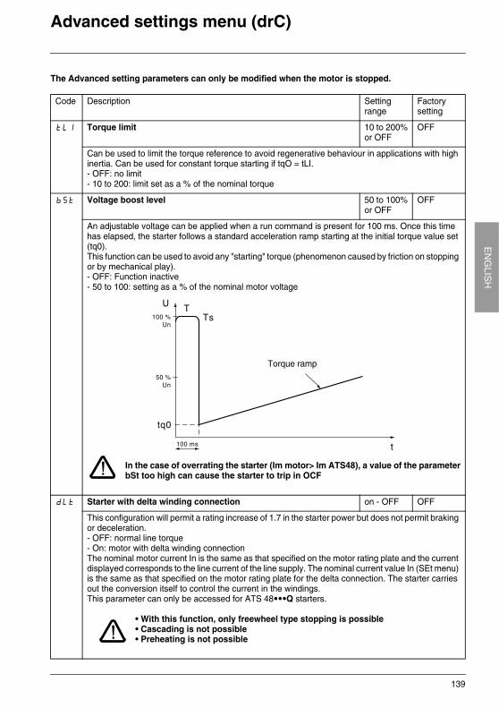
139
EN
GLIS
HAdvanced settings menu (drC)
The Advanced setting parameters can only be modified when the motor is stopped.
Code Description Settingrange
Factory setting
tLI Torque limit 10 to 200%or OFF
OFF
Can be used to limit the torque reference to avoid regenerative behaviour in applications with high inertia. Can be used for constant torque starting if tqO = tLI.- OFF: no limit- 10 to 200: limit set as a % of the nominal torque
bSt Voltage boost level 50 to 100%or OFF
OFF
An adjustable voltage can be applied when a run command is present for 100 ms. Once this time has elapsed, the starter follows a standard acceleration ramp starting at the initial torque value set (tq0).This function can be used to avoid any "starting" torque (phenomenon caused by friction on stopping or by mechanical play).- OFF: Function inactive- 50 to 100: setting as a % of the nominal motor voltage
In the case of overrating the starter (Im motor> Im ATS48), a value of the parameterbSt too high can cause the starter to trip in OCF
dLt Starter with delta winding connection on - OFF OFF
This configuration will permit a rating increase of 1.7 in the starter power but does not permit braking or deceleration.- OFF: normal line torque- On: motor with delta winding connectionThe nominal motor current In is the same as that specified on the motor rating plate and the current displayed corresponds to the line current of the line supply. The nominal current value In (SEt menu) is the same as that specified on the motor rating plate for the delta connection. The starter carries out the conversion itself to control the current in the windings.This parameter can only be accessed for ATS 48•••Q starters.
• With this function, only freewheel type stopping is possible• Cascading is not possible• Preheating is not possible
Torque ramp
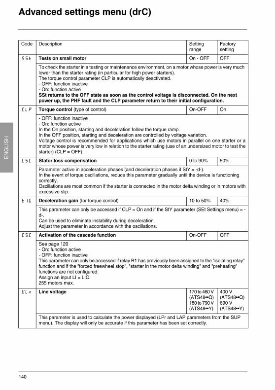
140
EN
GLI
SH
Advanced settings menu (drC)
Code Description Settingrange
Factory setting
SSt Tests on small motor On - OFF OFF
To check the starter in a testing or maintenance environment, on a motor whose power is very much lower than the starter rating (in particular for high power starters). The torque control parameter CLP is automatically deactivated.- OFF: function inactive- On: function activeSSt returns to the OFF state as soon as the control voltage is disconnected. On the next power up, the PHF fault and the CLP parameter return to their initial configuration.
CLP Torque control (type of control) On-OFF On
- OFF: function inactive- On: function activeIn the On position, starting and deceleration follow the torque ramp.In the OFF position, starting and deceleration are controlled by voltage variation.Voltage control is recommended for applications which use motors in parallel on one starter or amotor whose power is very low in relation to the starter rating (use of an undersized motor to test thestarter) (CLP = OFF).
LSC Stator loss compensation 0 to 90% 50%
Parameter active in acceleration phases (and deceleration phases if StY = -d-).In the event of torque oscillations, reduce this parameter gradually until the device is functioning correctly.Oscillations are most common if the starter is connected in the motor delta winding or in motors withexcessive slip.
tIG Deceleration gain (for torque control) 10 to 50% 40%
This parameter can only be accessed if CLP = On and if the StY parameter (SEt Settings menu) = -d-.Can be used to eliminate instability during deceleration.Adjust the parameter in accordance with the oscillations.
CSC Activation of the cascade function On-OFF OFF
See page 120- On: function active- OFF: function inactiveThis parameter can only be accessed if relay R1 has previously been assigned to the "isolating relay" function and if the "forced freewheel stop", "starter in the motor delta winding" and "preheating" functions are not configured.Assign an input LI = LIC.255 motors max.
ULn Line voltage 170 to 460 V (ATS48••Q)180 to 790 V (ATS48••Y)
400 V(ATS48••Q)690 V (ATS48••Y)
This parameter is used to calculate the power displayed (LPr and LAP parameters from the SUP menu). The display will only be accurate if this parameter has been set correctly.
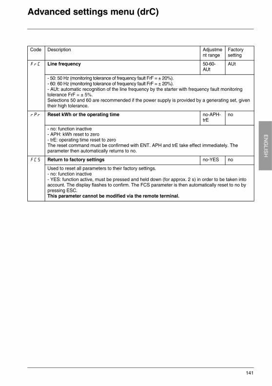
141
EN
GLIS
HAdvanced settings menu (drC)
Code Description Adjustment range
Factory setting
FrC Line frequency 50-60-AUt
AUt
- 50: 50 Hz (monitoring tolerance of frequency fault FrF = ± 20%).- 60: 60 Hz (monitoring tolerance of frequency fault FrF = ± 20%).- AUt: automatic recognition of the line frequency by the starter with frequency fault monitoring tolerance FrF = ± 5%. Selections 50 and 60 are recommended if the power supply is provided by a generating set, given their high tolerance.
rPr Reset kWh or the operating time no-APH-trE
no
- no: function inactive- APH: kWh reset to zero- trE: operating time reset to zeroThe reset command must be confirmed with ENT. APH and trE take effect immediately. The parameter then automatically returns to no.
FCS Return to factory settings no-YES no
Used to reset all parameters to their factory settings.- no: function inactive- YES: function active, must be pressed and held down (for approx. 2 s) in order to be taken into account. The display flashes to confirm. The FCS parameter is then automatically reset to no by pressing ESC.This parameter cannot be modified via the remote terminal.
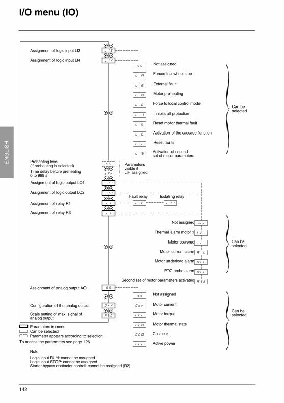
142
EN
GLI
SH
I/O menu (IO)
Parameters in menuCan be selectedParameter appears according to selection
Assignment of logic input LI3
Assignment of logic input LI4Not assigned
Forced freewheel stop
External fault
Motor preheating
Force to local control mode
Inhibits all protection
Reset motor thermal fault
Activation of the cascade function
Reset faults
Activation of second set of motor parameters
Preheating level (if preheating is selected)Time delay before preheating 0 to 999 s
Parameters visible if LIH assigned
Fault relay Isolating relay
Assignment of logic output LO1
Assignment of logic output LO2
Assignment of relay R1
Assignment of relay R3
Not assigned
Thermal alarm motor 1
Motor powered
Motor underload alarm
PTC probe alarm
Second set of motor parameters activated
Assignment of analog output AO
Not assigned
Motor current
Motor torque
Motor thermal state
Cosine ϕ
Active power
Configuration of the analog output
Scale setting of max. signal of analog output
Motor current alarm
Can be selected
Can be selected
Can be selected
To access the parameters see page 126
Note
Logic input RUN: cannot be assignedLogic input STOP: cannot be assignedStarter bypass contactor control: cannot be assigned (R2)
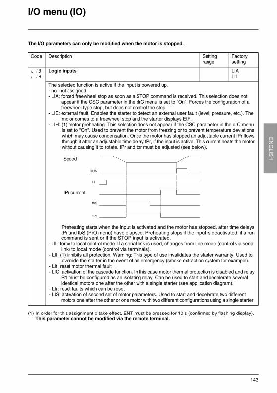
143
EN
GLIS
HI/O menu (IO)
The I/O parameters can only be modified when the motor is stopped.
(1) In order for this assignment o take effect, ENT must be pressed for 10 s (confirmed by flashing display).This parameter cannot be modified via the remote terminal.
Code Description Settingrange
Factory setting
LI3LI4
Logic inputs LIALIL
The selected function is active if the input is powered up.- no: not assigned.- LIA: forced freewheel stop as soon as a STOP command is received. This selection does not
appear if the CSC parameter in the drC menu is set to "On". Forces the configuration of a freewheel type stop, but does not control the stop.
- LIE: external fault. Enables the starter to detect an external user fault (level, pressure, etc.). The motor comes to a freewheel stop and the starter displays EtF.
- LIH: (1) motor preheating. This selection does not appear if the CSC parameter in the drC menu is set to "On". Used to prevent the motor from freezing or to prevent temperature deviations which may cause condensation. Once the motor has stopped an adjustable current IPr flows through it after an adjustable time delay tPr, if the input is active. This current heats the motor without causing it to rotate. IPr and tbr must be adjusted (see below).
Preheating starts when the input is activated and the motor has stopped, after time delays tPr and tbS (PrO menu) have elapsed. Preheating stops if the input is deactivated, if a run command is sent or if the STOP input is activated.
- LIL: force to local control mode. If a serial link is used, changes from line mode (control via serial link) to local mode (control via terminals).
- LII: (1) inhibits all protection. Warning: This type of use invalidates the starter warranty. Used to override the starter in the event of an emergency (smoke extraction system for example).
- LIt: reset motor thermal fault- LIC: activation of the cascade function. In this case motor thermal protection is disabled and relay
R1 must be configured as an isolating relay. Can be used to start and decelerate several identical motors one after the other with a single starter (see application diagram).
- LIr: reset faults which can be reset- LIS: activation of second set of motor parameters. Used to start and decelerate two different
motors one after the other or one motor with two different configurations using a single starter.
Speed
IPr current
RUN
LI
tbS
tPr
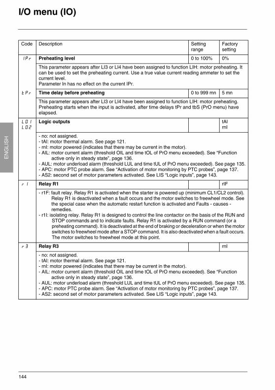
144
EN
GLI
SH
I/O menu (IO)
Code Description Settingrange
Factory setting
IPr Preheating level 0 to 100% 0%
This parameter appears after LI3 or LI4 have been assigned to function LIH: motor preheating. It can be used to set the preheating current. Use a true value current reading ammeter to set the current level.Parameter In has no effect on the current IPr.
tPr Time delay before preheating 0 to 999 mn 5 mn
This parameter appears after LI3 or LI4 have been assigned to function LIH: motor preheating. Preheating starts when the input is activated, after time delays tPr and tbS (PrO menu) have elapsed.
LO1LO2
Logic outputs tAIrnI
- no: not assigned.- tAI: motor thermal alarm. See page 121.- rnI: motor powered (indicates that there may be current in the motor). - AIL: motor current alarm (threshold OIL and time tOL of PrO menu exceeded). See “Function
active only in steady state”, page 136.- AUL: motor underload alarm (threshold LUL and time tUL of PrO menu exceeded). See page 135.- APC: motor PTC probe alarm. See “Activation of motor monitoring by PTC probes”, page 137.- AS2: second set of motor parameters activated. See LIS “Logic inputs”, page 143.
r1 Relay R1 rIF
- r1F: fault relay. Relay R1 is activated when the starter is powered up (minimum CL1/CL2 control). Relay R1 is deactivated when a fault occurs and the motor switches to freewheel mode. See the special case when the automatic restart function is activated and Faults - causes - remedies.
- r1I: isolating relay. Relay R1 is designed to control the line contactor on the basis of the RUN and STOP commands and to indicate faults. Relay R1 is activated by a RUN command (or a preheating command). It is deactivated at the end of braking or deceleration or when the motor switches to freewheel mode after a STOP command. It is also deactivated when a fault occurs. The motor switches to freewheel mode at this point.
r3 Relay R3 rnI
- no: not assigned.- tAI: motor thermal alarm. See page 121.- rnI: motor powered (indicates that there may be current in the motor). - AIL: motor current alarm (threshold OIL and time tOL of PrO menu exceeded). See “Function
active only in steady state”, page 136.- AUL: motor underload alarm (threshold LUL and time tUL of PrO menu exceeded). See page 135.- APC: motor PTC probe alarm. See “Activation of motor monitoring by PTC probes”, page 137.- AS2: second set of motor parameters activated. See LIS “Logic inputs”, page 143.
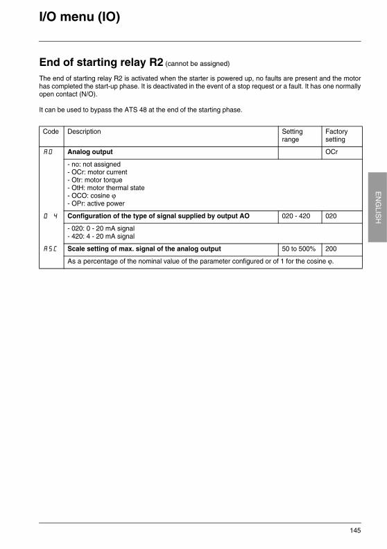
145
EN
GLIS
HI/O menu (IO)
End of starting relay R2 (cannot be assigned)
The end of starting relay R2 is activated when the starter is powered up, no faults are present and the motorhas completed the start-up phase. It is deactivated in the event of a stop request or a fault. It has one normallyopen contact (N/O).
It can be used to bypass the ATS 48 at the end of the starting phase.
Code Description Settingrange
Factory setting
AO Analog output OCr
- no: not assigned- OCr: motor current- Otr: motor torque- OtH: motor thermal state- OCO: cosine ϕ- OPr: active power
O 4 Configuration of the type of signal supplied by output AO 020 - 420 020
- 020: 0 - 20 mA signal - 420: 4 - 20 mA signal
ASC Scale setting of max. signal of the analog output 50 to 500% 200
As a percentage of the nominal value of the parameter configured or of 1 for the cosine ϕ.
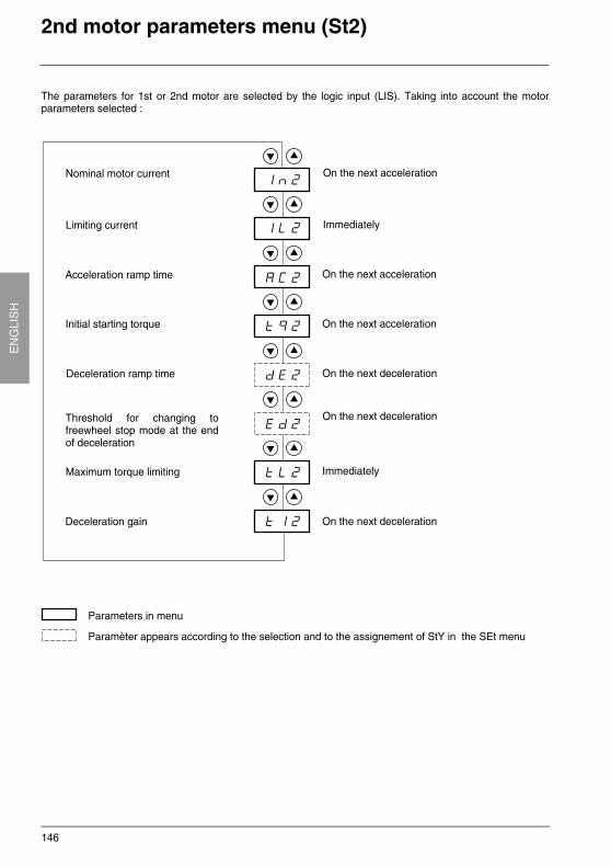
146
EN
GLI
SH
2nd motor parameters menu (St2)
The parameters for 1st or 2nd motor are selected by the logic input (LIS). Taking into account the motorparameters selected :
Parameters in menu
Paramèter appears according to the selection and to the assignement of StY in the SEt menu
Nominal motor current
Limiting current
Acceleration ramp time
Initial starting torque
Deceleration ramp time
Threshold for changing tofreewheel stop mode at the endof deceleration
Maximum torque limiting
Deceleration gain
On the next deceleration
On the next deceleration
On the next acceleration
Immediately
On the next acceleration
On the next acceleration
Immediately
On the next deceleration
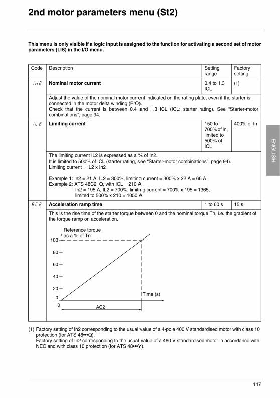
147
EN
GLIS
H2nd motor parameters menu (St2)
This menu is only visible if a logic input is assigned to the function for activating a second set of motorparameters (LIS) in the I/O menu.
(1) Factory setting of In2 corresponding to the usual value of a 4-pole 400 V standardised motor with class 10 protection (for ATS 48•••Q).Factory setting of In2 corresponding to the usual value of a 460 V standardised motor in accordance with NEC and with class 10 protection (for ATS 48•••Y).
Code Description Settingrange
Factory setting
In2 Nominal motor current 0.4 to 1.3 ICL
(1)
Adjust the value of the nominal motor current indicated on the rating plate, even if the starter is connected in the motor delta winding (PrO).Check that the current is between 0.4 and 1.3 ICL (ICL: starter rating). See “Starter-motorcombinations”, page 94.
IL2 Limiting current 150 to 700% of In, limited to 500% of ICL
400% of In
The limiting current IL2 is expressed as a % of In2. It is limited to 500% of ICL (starter rating, see “Starter-motor combinations”, page 94).Limiting current = IL2 x In2
Example 1: In2 = 21 A, IL2 = 300%, limiting current = 300% x 22 A = 66 AExample 2: ATS 48C21Q, with ICL = 210 A
In2 = 195 A, IL2 = 700%, limiting current = 700% x 195 = 1365, limited to 500% x 210 = 1050 A
AC2 Acceleration ramp time 1 to 60 s 15 s
This is the rise time of the starter torque between 0 and the nominal torque Tn, i.e. the gradient of the torque ramp on acceleration.
Time (s)
Reference torqueas a % of Tn
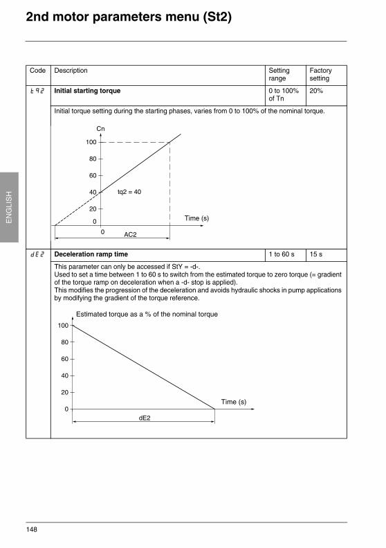
148
EN
GLI
SH
2nd motor parameters menu (St2)
Code Description Settingrange
Factory setting
tq2 Initial starting torque 0 to 100% of Tn
20%
Initial torque setting during the starting phases, varies from 0 to 100% of the nominal torque.
dE2 Deceleration ramp time 1 to 60 s 15 s
This parameter can only be accessed if StY = -d-.Used to set a time between 1 to 60 s to switch from the estimated torque to zero torque (= gradient of the torque ramp on deceleration when a -d- stop is applied).This modifies the progression of the deceleration and avoids hydraulic shocks in pump applications by modifying the gradient of the torque reference.
Time (s)
Time (s)
Estimated torque as a % of the nominal torque
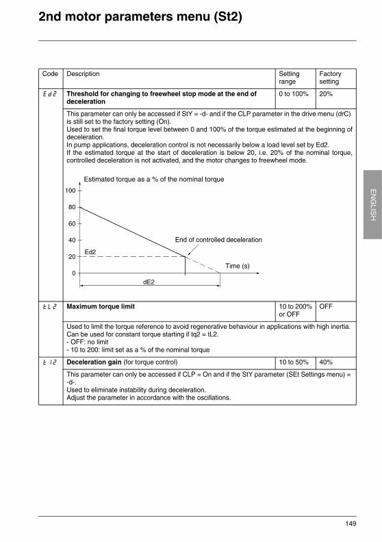
149
EN
GLIS
H2nd motor parameters menu (St2)
Code Description Settingrange
Factory setting
Ed2 Threshold for changing to freewheel stop mode at the end of deceleration
0 to 100% 20%
This parameter can only be accessed if StY = -d- and if the CLP parameter in the drive menu (drC) is still set to the factory setting (On).Used to set the final torque level between 0 and 100% of the torque estimated at the beginning ofdeceleration.In pump applications, deceleration control is not necessarily below a load level set by Ed2.If the estimated torque at the start of deceleration is below 20, i.e. 20% of the nominal torque,controlled deceleration is not activated, and the motor changes to freewheel mode.
tL2 Maximum torque limit 10 to 200%or OFF
OFF
Used to limit the torque reference to avoid regenerative behaviour in applications with high inertia. Can be used for constant torque starting if tq2 = tL2.- OFF: no limit- 10 to 200: limit set as a % of the nominal torque
tI2 Deceleration gain (for torque control) 10 to 50% 40%
This parameter can only be accessed if CLP = On and if the StY parameter (SEt Settings menu) = -d-.Used to eliminate instability during deceleration.Adjust the parameter in accordance with the oscillations.
Time (s)
Estimated torque as a % of the nominal torque
End of controlled deceleration

150
EN
GLI
SH
Communication menu (COP)
Add
tbr
FOr
tLP
PCt
Parameters in menu
Starter address
Communication speed
Communication format
Serial link timeout setting
Configuration of the link forcommunication with the remote terminalor the software workshop
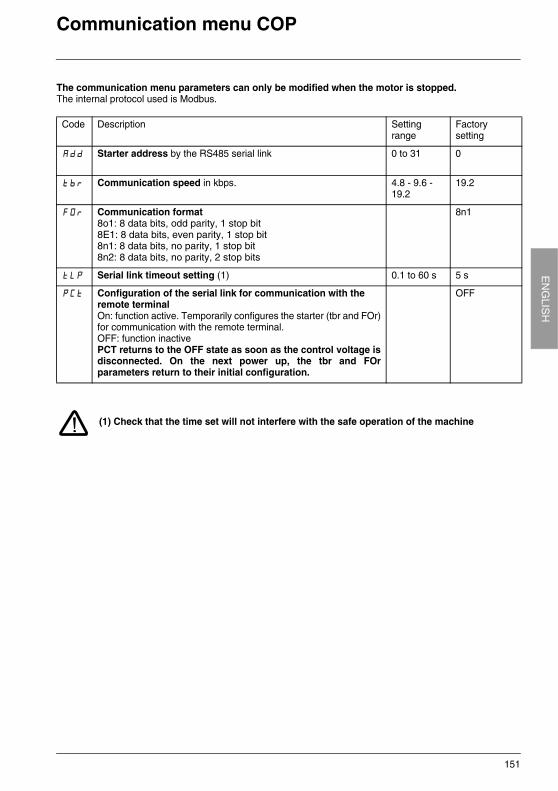
151
EN
GLIS
HCommunication menu COP
The communication menu parameters can only be modified when the motor is stopped.The internal protocol used is Modbus.
(1) Check that the time set will not interfere with the safe operation of the machine
Code Description Settingrange
Factory setting
Add Starter address by the RS485 serial link 0 to 31 0
tbr Communication speed in kbps. 4.8 - 9.6 - 19.2
19.2
FOr Communication format8o1: 8 data bits, odd parity, 1 stop bit8E1: 8 data bits, even parity, 1 stop bit8n1: 8 data bits, no parity, 1 stop bit8n2: 8 data bits, no parity, 2 stop bits
8n1
tLP Serial link timeout setting (1) 0.1 to 60 s 5 s
PCt Configuration of the serial link for communication with the remote terminalOn: function active. Temporarily configures the starter (tbr and FOr)for communication with the remote terminal.OFF: function inactivePCT returns to the OFF state as soon as the control voltage isdisconnected. On the next power up, the tbr and FOrparameters return to their initial configuration.
OFF
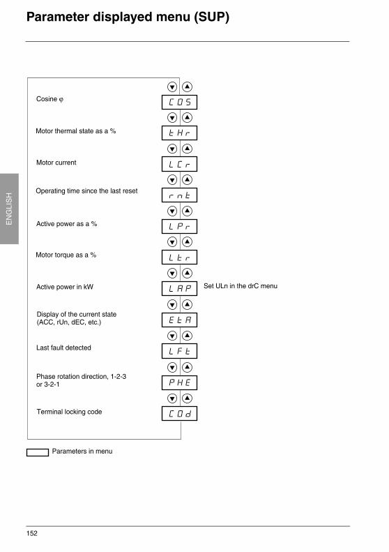
152
EN
GLI
SH
Parameter displayed menu (SUP)
Parameters in menu
Cosine ϕ
Motor thermal state as a %
Motor current
Operating time since the last reset
Active power as a %
Motor torque as a %
Active power in kW
Display of the current state(ACC, rUn, dEC, etc.)
Phase rotation direction, 1-2-3or 3-2-1
Terminal locking code
Set ULn in the drC menu
Last fault detected
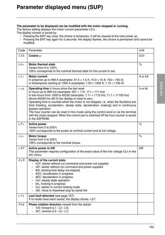
153
EN
GLIS
HParameter displayed menu (SUP)
The parameter to be displayed can be modified with the motor stopped or running. The factory setting displays the motor current (parameter LCr).The display chosen is saved by:
- Pressing the ENT key once: the choice is temporary, it will be cleared at the next power up.- Pressing the ENT key again for 2 seconds: the display flashes, the choice is permanent and cannot be
modified.
Code Parameter Unit
COS Cosine ϕ 0.01
tHr Motor thermal stateVaries from 0 to 125%100% corresponds to the nominal thermal state for the current In set.
%
LCr Motor currentIn amperes up to 999 A (examples: 01.5 = 1.5 A; 15.0 = 15 A; 150 = 150 A)In kiloamperes starting at 1000 A (examples: 1.50 = 1500 A; 1.15 = 1150 A)
A or kA
rnt Operating time in hours since the last reset.In hours up to 999 hrs (examples: 001 = 1 hr; 111 = 111 hrs)In kilo-hours from 1000 to 65535 (examples: 1.11 = 1110 hrs; 11.1 = 11100 hrs)Above 65535 hrs (65.5) the display is reset to zero.Operating time is counted when the motor is not stopped, i.e. when the thyristors arefired (heating, acceleration, steady state, deceleration, braking) and in continuousbypass operation. The hour counter can be reset in line mode using the control word or via the terminalwith the motor stopped. When the control part is switched off the hour counter is savedin the EEPROM.
h or kh
LPr Active powerVaries from 0 to 255%100% corresponds to the power at nominal current and at full voltage.
%
Ltr Motor torqueVaries from 0 to 255%100% corresponds to the nominal torque.
%
LAP Active power in kWThis parameter requires configuration of the exact value of the line voltage ULn in thedrC menu.
kW
EtA Display of the current state- nLP: starter without run command and power not supplied- rdY: starter without run command and power supplied- tbS: starting time delay not elapsed- ACC: acceleration in progress- dEC: deceleration in progress- rUn: steady state operation- brL: braking in progress- CLI: starter in current limiting mode- nSt : force to freewheel stop by serial link
LFt Last fault detected (see page 157).If no faults have been saved, the display shows nOF.
PHE Phase rotation direction viewed from the starter- 123: forward (L1 - L2 - L3)- 321: reverse (L3 - L2 - L1)
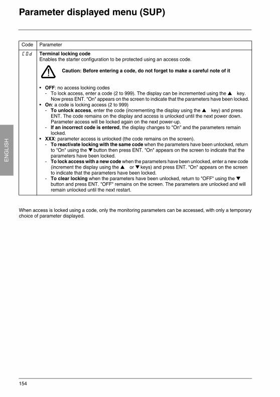
154
EN
GLI
SH
Parameter displayed menu (SUP)
When access is locked using a code, only the monitoring parameters can be accessed, with only a temporarychoice of parameter displayed.
Code Parameter
COd Terminal locking codeEnables the starter configuration to be protected using an access code.
Caution: Before entering a code, do not forget to make a careful note of it
• OFF: no access locking codes- To lock access, enter a code (2 to 999). The display can be incremented using the key.
Now press ENT. "On" appears on the screen to indicate that the parameters have been locked.• On: a code is locking access (2 to 999)
- To unlock access, enter the code (incrementing the display using the key) and press ENT. The code remains on the display and access is unlocked until the next power down. Parameter access will be locked again on the next power-up.
- If an incorrect code is entered, the display changes to "On" and the parameters remain locked.
• XXX: parameter access is unlocked (the code remains on the screen).- To reactivate locking with the same code when the parameters have been unlocked, return
to "On" using the button then press ENT. "On" appears on the screen to indicate that the parameters have been locked.
- To lock access with a new code when the parameters have been unlocked, enter a new code (increment the display using the or keys) and press ENT. "On" appears on the screen to indicate that the parameters have been locked.
- To clear locking when the parameters have been unlocked, return to "OFF" using the button and press ENT. "OFF" remains on the screen. The parameters are unlocked and will remain unlocked until the next restart.
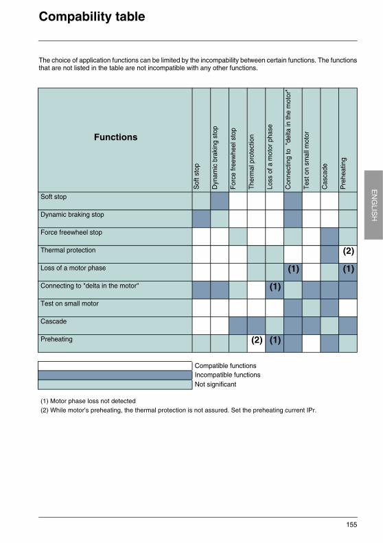
155
EN
GLIS
HCompability table
The choice of application functions can be limited by the incompability between certain functions. The functionsthat are not listed in the table are not incompatible with any other functions.
Functions
Sof
t sto
p
Dyn
amic
bra
king
sto
p
For
ce fr
eew
heel
sto
p
The
rmal
pro
tect
ion
Loss
of a
mot
or p
hase
Con
nect
ing
to "
delta
in th
e m
otor
"
Tes
t on
smal
l mot
or
Cas
cade
Pre
heat
ing
Soft stop
Dynamic braking stop
Force freewheel stop
Thermal protection (2)
Loss of a motor phase (1) (1)
Connecting to "delta in the motor" (1)
Test on small motor
Cascade
Preheating (2) (1)
Compatible functionsIncompatible functionsNot significant
(1) Motor phase loss not detected(2) While motor’s preheating, the thermal protection is not assured. Set the preheating current IPr.
156
EN
GLI
SH
Maintenance
ServicingThe ATS 48 does not require any preventative maintenance. It is nevertheless advisable to perform thefollowing regularly:
- Check the condition and tightness of connections- Ensure that the temperature around the unit remains at an acceptable level and that ventilation is effective
(average service life of fans: 3 to 5 years depending on the operating conditions)- Remove any dust from the heatsink if necessary
Assistance with maintenanceIf a problem arises during setup or operation, ensure that the recommendations relating to the environment,mounting and connections have been observed.
The first fault detected is memorized and displayed on the screen: the starter locks and relays R1 and R2change state according to their assignment.
Clearing the faultSwitch off the starter power supply in the event of a fault which cannot be reset.Wait for the display to go off completely.Find the cause of the fault in order to correct it.Restore the power supply: this clears the fault if it has disappeared.
In some cases there may be an automatic restart once the fault has disappeared if this function has beenprogrammed.
Monitoring menuThis is used to prevent and find the causes of faults by displaying the starter status and its current values.
Spares and repairs Consult Schneider Electric product support.
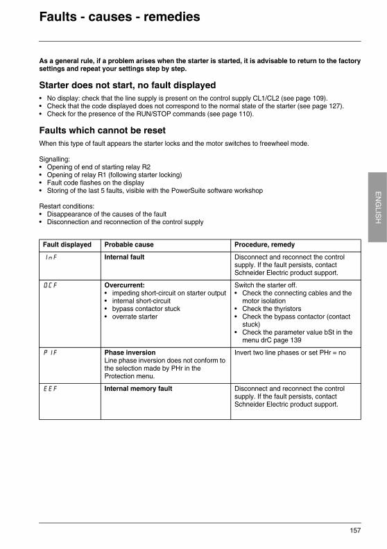
157
EN
GLIS
HFaults - causes - remedies
As a general rule, if a problem arises when the starter is started, it is advisable to return to the factorysettings and repeat your settings step by step.
Starter does not start, no fault displayed• No display: check that the line supply is present on the control supply CL1/CL2 (see page 109).• Check that the code displayed does not correspond to the normal state of the starter (see page 127).• Check for the presence of the RUN/STOP commands (see page 110).
Faults which cannot be resetWhen this type of fault appears the starter locks and the motor switches to freewheel mode.
Signalling:• Opening of end of starting relay R2• Opening of relay R1 (following starter locking)• Fault code flashes on the display• Storing of the last 5 faults, visible with the PowerSuite software workshop
Restart conditions:• Disappearance of the causes of the fault• Disconnection and reconnection of the control supply
Fault displayed Probable cause Procedure, remedy
InF Internal fault Disconnect and reconnect the control supply. If the fault persists, contact Schneider Electric product support.
OCF Overcurrent:• impeding short-circuit on starter output• internal short-circuit • bypass contactor stuck• overrate starter
Switch the starter off.• Check the connecting cables and the
motor isolation• Check the thyristors• Check the bypass contactor (contact
stuck)• Check the parameter value bSt in the
menu drC page 139
PIF Phase inversionLine phase inversion does not conform to the selection made by PHr in the Protection menu.
Invert two line phases or set PHr = no
EEF Internal memory fault Disconnect and reconnect the control supply. If the fault persists, contact Schneider Electric product support.
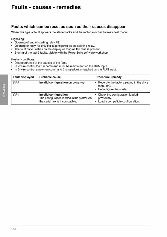
158
EN
GLI
SH
Faults - causes - remedies
Faults which can be reset as soon as their causes disappearWhen this type of fault appears the starter locks and the motor switches to freewheel mode.
Signalling:• Opening of end of starting relay R2.• Opening of relay R1 only if it is configured as an isolating relay.• The fault code flashes on the display as long as the fault is present.• Storing of the last 5 faults, visible with the PowerSuite software workshop.
Restart conditions:• Disappearance of the causes of the fault.• In 2-wire control the run command must be maintained on the RUN input.• In 3-wire control a new run command (rising edge) is required on the RUN input.
Fault displayed Probable cause Procedure, remedy
CFF Invalid configuration on power-up • Revert to the factory setting in the drive menu drC.
• Reconfigure the starter.
CFI Invalid configurationThe configuration loaded in the starter via the serial link is incompatible.
• Check the configuration loaded previously.
• Load a compatible configuration.
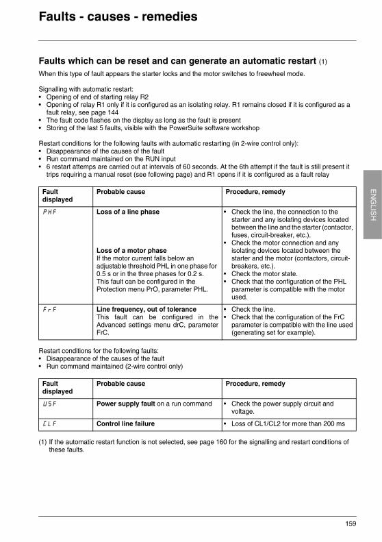
159
EN
GLIS
HFaults - causes - remedies
Faults which can be reset and can generate an automatic restart (1)
When this type of fault appears the starter locks and the motor switches to freewheel mode.
Signalling with automatic restart:• Opening of end of starting relay R2• Opening of relay R1 only if it is configured as an isolating relay. R1 remains closed if it is configured as a
fault relay, see page 144• The fault code flashes on the display as long as the fault is present• Storing of the last 5 faults, visible with the PowerSuite software workshop
Restart conditions for the following faults with automatic restarting (in 2-wire control only):• Disappearance of the causes of the fault• Run command maintained on the RUN input• 6 restart attemps are carried out at intervals of 60 seconds. At the 6th attempt if the fault is still present it
trips requiring a manual reset (see following page) and R1 opens if it is configured as a fault relay
Restart conditions for the following faults:• Disappearance of the causes of the fault• Run command maintained (2-wire control only)
(1) If the automatic restart function is not selected, see page 160 for the signalling and restart conditions of these faults.
Fault displayed
Probable cause Procedure, remedy
PHF Loss of a line phase
Loss of a motor phaseIf the motor current falls below an adjustable threshold PHL in one phase for 0.5 s or in the three phases for 0.2 s.This fault can be configured in the Protection menu PrO, parameter PHL.
• Check the line, the connection to the starter and any isolating devices located between the line and the starter (contactor, fuses, circuit-breaker, etc.).
• Check the motor connection and any isolating devices located between the starter and the motor (contactors, circuit-breakers, etc.).
• Check the motor state.• Check that the configuration of the PHL
parameter is compatible with the motor used.
FrF Line frequency, out of toleranceThis fault can be configured in theAdvanced settings menu drC, parameterFrC.
• Check the line. • Check that the configuration of the FrC
parameter is compatible with the line used (generating set for example).
Fault displayed
Probable cause Procedure, remedy
USF Power supply fault on a run command • Check the power supply circuit and voltage.
CLF Control line failure • Loss of CL1/CL2 for more than 200 ms
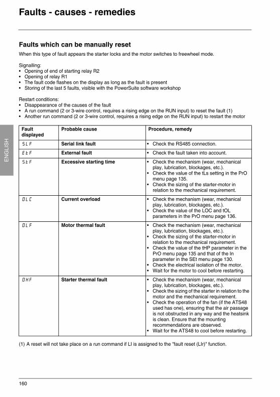
160
EN
GLI
SH
Faults - causes - remedies
Faults which can be manually resetWhen this type of fault appears the starter locks and the motor switches to freewheel mode.
Signalling:• Opening of end of starting relay R2• Opening of relay R1• The fault code flashes on the display as long as the fault is present• Storing of the last 5 faults, visible with the PowerSuite software workshop
Restart conditions:• Disappearance of the causes of the fault• A run command (2 or 3-wire control, requires a rising edge on the RUN input) to reset the fault (1)• Another run command (2 or 3-wire control, requires a rising edge on the RUN input) to restart the motor
(1) A reset will not take place on a run command if LI is assigned to the "fault reset (LIr)" function.
Fault displayed
Probable cause Procedure, remedy
SLF Serial link fault • Check the RS485 connection.
EtF External fault • Check the fault taken into account.
StF Excessive starting time • Check the mechanism (wear, mechanical play, lubrication, blockages, etc.).
• Check the value of the tLs setting in the PrO menu page 135.
• Check the sizing of the starter-motor in relation to the mechanical requirement.
OLC Current overload • Check the mechanism (wear, mechanical play, lubrication, blockages, etc.).
• Check the value of the LOC and tOL parameters in the PrO menu page 136.
OLF Motor thermal fault • Check the mechanism (wear, mechanical play, lubrication, blockages, etc.).
• Check the sizing of the starter-motor in relation to the mechanical requirement.
• Check the value of the tHP parameter in the PrO menu page 135 and that of the In parameter in the SEt menu page 130.
• Check the electrical isolation of the motor.• Wait for the motor to cool before restarting.
OHF Starter thermal fault • Check the mechanism (wear, mechanical play, lubrication, blockages, etc.).
• Check the sizing of the starter in relation to the motor and the mechanical requirement.
• Check the operation of the fan (if the ATS48 used has one), ensuring that the air passage is not obstructed in any way and the heatsink is clean. Ensure that the mounting recommendations are observed.
• Wait for the ATS48 to cool before restarting.
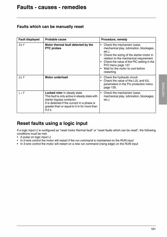
161
EN
GLIS
HFaults - causes - remedies
Faults which can be manually reset
Reset faults using a logic inputIf a logic input LI is configured as "reset motor thermal fault" or "reset faults which can be reset", the followingconditions must be met: • A pulse on logic input LI• In 2-wire control the motor will restart if the run command is maintained on the RUN input• In 3-wire control the motor will restart on a new run command (rising edge) on the RUN input
Fault displayed Probable cause Procedure, remedy
OtF Motor thermal fault detected by the PTC probes
• Check the mechanism (wear, mechanical play, lubrication, blockages, etc.).
• Check the sizing of the starter-motor in relation to the mechanical requirement.
• Check the value of the PtC setting in the PrO menu page 137.
• Wait for the motor to cool before restarting.
ULF Motor underload • Check the hydraulic circuit.• Check the value of the LUL and tUL
parameters in the Pro protection menu page 135.
LrF Locked rotor in steady stateThis fault is only active in steady state with starter bypass contactor. It is detected if the current in a phase is greater than or equal to 5 In for more than 0.2 s.
• Check the mechanism (wear, mechanical play, lubrication, blockages, etc.).
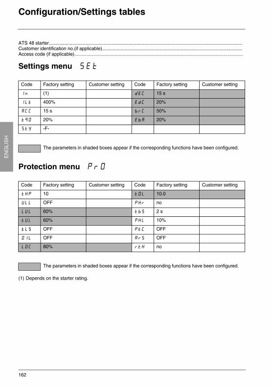
162
EN
GLI
SH
Configuration/Settings tables
ATS 48 starter....................................................................................................................................................Customer identification no.(if applicable)...........................................................................................................Access code (if applicable).................................................................................................................................
Settings menu SEt
Protection menu PrO
(1) Depends on the starter rating.
Code Factory setting Customer setting Code Factory setting Customer setting
In (1) dEC 15 s
ILt 400% EdC 20%
ACC 15 s brC 50%
tq0 20% EbA 20%
StY -F-
The parameters in shaded boxes appear if the corresponding functions have been configured.
Code Factory setting Customer setting Code Factory setting Customer setting
tHP 10 tOL 10.0
ULL OFF PHr no
LUL 60% tbS 2 s
tUL 60% PHL 10%
tLS OFF PtC OFF
OIL OFF ArS OFF
LOC 80% rtH no
The parameters in shaded boxes appear if the corresponding functions have been configured.
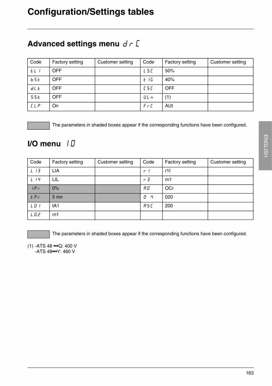
163
EN
GLIS
HConfiguration/Settings tables
Advanced settings menu drC
I/O menu IO
(1) -ATS 48 •••Q: 400 V-ATS 48•••Y: 460 V
Code Factory setting Customer setting Code Factory setting Customer setting
tLI OFF LSC 50%
bSt OFF tIG 40%
dLt OFF CSC OFF
SSt OFF ULn (1)
CLP On FrC AUt
The parameters in shaded boxes appear if the corresponding functions have been configured.
Code Factory setting Customer setting Code Factory setting Customer setting
LI3 LIA r1 r1I
LI4 LIL r3 rn1
IPr 0% AO OCr
tPr 5 mn O 4 020
LO1 tA1 ASC 200
LO2 rn1
The parameters in shaded boxes appear if the corresponding functions have been configured.
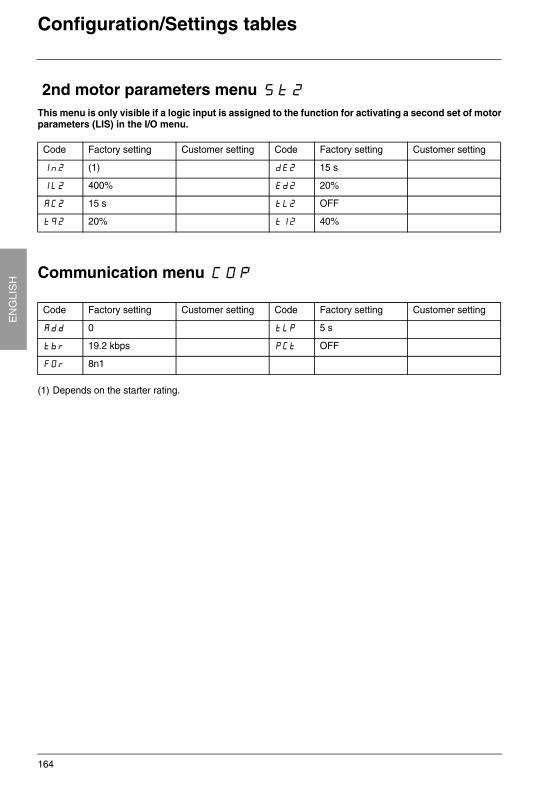
164
EN
GLI
SH
Configuration/Settings tables
2nd motor parameters menu St2This menu is only visible if a logic input is assigned to the function for activating a second set of motorparameters (LIS) in the I/O menu.
Communication menu COP
(1) Depends on the starter rating.
Code Factory setting Customer setting Code Factory setting Customer setting
In2 (1) dE2 15 s
IL2 400% Ed2 20%
AC2 15 s tL2 OFF
tq2 20% tI2 40%
Code Factory setting Customer setting Code Factory setting Customer setting
Add 0 tLP 5 s
tbr 19.2 kbps PCt OFF
FOr 8n1
施耐德电气(中国)投资有限公司
施耐德电气(中国)投资有限公司 北京市朝阳区将台路 2号和乔丽晶中心施耐德大厦 邮编: 100016 电话: (010) 84346699 传真: (010) 84501130
上海分公司 上海市宜山路 1009 号创新大厦 12,15,16 楼 邮编: 200233 电话: (021) 24012500 传真: (021) 24012950
广州分公司 广州市环市东路 403 号广州国际电子大厦 31 楼 邮编: 510095 电话: (020) 87320138 传真: (020) 87321929
武汉分公司 武汉市建设大道568号新世界国贸大厦 I 座 37层01,02,03,05单元 邮编: 430022 电话: (027) 68850668 传真: (027) 68850488
南京办事处 南京市中山路 268 号汇杰广场 2001-2003 室 邮编: 210008 电话: (025) 83198399 传真: (025) 83198321/22
南宁办事处 南宁市南湖区民族大道 111号广西发展大厦 12 层 邮编: 530022 电话: (0771) 5519761/62 传真: (0771) 5519760
青岛办事处 青岛市香港中路 59 号国际金融中心 35 层 3501B 室 邮编: 266071 电话: (0532) 85793001 传真: (0532) 85793002
烟台办事处 烟台市南大街 9 号金都大厦 2516 室 邮编: 264001 电话: (0535) 3393899 传真: (0535) 3393998
深圳办事处 深圳市深南东路 5047 号深圳发展银行大厦 17 层 H 邮编: 518001 电话: (0755) 25841022/1488 传真: (0755) 82080250
大连办事处 大连市中山区同兴街 25 号大连世界贸易大厦 45 层 邮编: 116001 电话: (0411) 82530368 传真: (0411) 82531268
福州办事处 福州市五一中路 88 号平安大厦 12 层 D 单元 邮编: 350005 电话: (0591) 7114853 传真: (0591) 7112046
杭州办事处 杭州市凤起路 78 号浙金广场 4 楼 邮编: 310003 电话: (0571) 85271466 传真: (0571) 85271305
重庆办事处 重庆市渝中区邹容路 68 号大都会商厦 16 楼 1603 室 邮编: 400010 电话: (023) 63839700 传真: (023) 63839707
西安办事处 西安市高新区科技路 48 号创业广场B 座 17 层 邮编: 710075 电话: (029) 88332711 传真: (029) 88324697/4820
天津办事处 天津市河西区围堤道 125-127 号天信大厦 13 层 1305 室 邮编: 300074 电话: (022) 28408408 传真: (022) 28408410
长沙办事处 长沙市五一中路 68 号亚大时代 11 层 1106 室 邮编: 410011 电话: (0731) 4585710/11/12/13 传真: (0731) 4585709
昆明办事处 昆明市东风西路 123 号三和商利写字楼 14 层 D 座 邮编: 650032 电话: (0871) 3647549/50/58/59 传真: (0871) 3647552
成都办事处 成都市顺城大街 308 号冠城广场 27 楼 B, C, D, E, F 座 邮编: 610017 电话: (028) 86528282 传真: (028) 86528383
乌鲁木齐办事处 乌鲁木齐市新华北路 5 号美丽华酒店 2521 室 邮编: 830002 电话: (0991) 2825888-2521 传真: (0991) 2848188
沈阳办事处 沈阳市沈河区青年大街 219 号华新国际大厦 16 层 G, H, I 座 邮编: 110015 电话: (024) 23964339 传真: (024) 23964296/97
济南办事处 济南市泺源大街 229 号金龙中心主楼 21 层 D 座 邮编: 250012 电话: (0531) 86121765 传真: (0531) 86121628
苏州办事处 苏州市干将西路 1296 号 C1 区 700 室 邮编: 215004 电话: (0512) 68622550 传真: (0512) 68622597
宁波办事处 宁波市江东北路 1 号中信宁波国际大酒店 833 室 邮编: 315010 电话: (0574) 87716067 传真: (0574) 87724576
合肥办事处 合肥市长江路 1104 号古井假日酒店 820 室 邮编: 230001 电话: (0551) 4291993 4299891/92/93/95 传真: (0551) 2206956
郑州办事处 郑州市金水路 115 号中州假日宾馆 1 号楼 4 层 邮编: 450003 电话: (0371) 65939211/12 65935282 传真: (0371) 65939213
哈尔滨办事处 哈尔滨市南岗区红军街 15 号奥维斯发展大厦 22 层 A, B 座 邮编: 150001 电话: (0451) 53009797 传真: (0451) 53009639
厦门办事处 厦门市厦禾路 189 号银行中心 2502 室 邮编: 361003 电话: (0592) 2386700 传真: (0592) 2386701
石家庄办事处 石家庄市中山东路 303 号世贸皇冠酒店办公楼 12 层 1201 室 邮编: 050011 电话: (0311) 6698713 传真: (0311) 6698723
无锡办事处 无锡市中山路 343 号东方广场 19 层 D, E, F 座 邮编: 214001 电话: (0510) 2752575 传真: (0510) 2755950
长春办事处 长春市解放大路 2677 号长春光大大厦 1211-1212 室 邮编: 130061 电话: (0431) 8400302/03 传真: (0431) 8400301
东莞办事处 东莞市南城区体育路 2 号鸿禧中心 B 座 1003 室 邮编: 523070 电话: (0769) 22428234 传真: (0769) 22413160
太原办事处 太原市府西街 268 号力鸿大厦 1003 室 邮编: 030002 电话: (0351) 4937186/4937025 传真: (0351) 4937029
中山办事处 中山市中山三路 18 号中银大厦 18 楼 1813 室 邮编: 528403 电话: (0760) 8235971/72/73 传真: (0760) 8235979
洛阳办事处 洛阳市涧西区凯旋西路 88 号华阳广场国际大酒店 609 室 邮编: 471003 电话: (0379) 65588678 传真: (0379) 65588679
常州办事处 常州市局前街 2 号椿庭楼宾馆 1216 室 邮编: 213003 电话: (0519) 8130710 传真: (0519) 8130711
佛山办事处 佛山市祖庙路百花广场 2823 室 邮编: 528000 电话: (0757) 83992619/0029 传真: (0757) 83991312
施耐德电气(香港)有限公司 香港 鱼涌英皇道 979 号太古坊和域大厦 13 楼东翼 电话: (00852) 25650621 传真: (00852) 28111029
施耐德电气中国研修学院 北京市朝阳区将台路 2号和乔丽晶中心施耐德大厦 邮编: 100016 电话: (010) 84346699 传真: (010) 84501137
鲜则

SC DOC 415-VVD 2007.05
施耐德电气公司
Schneider Electric Chinawww.schneider-electric.com.cn
北京市朝阳区将台路 2 号
和乔丽晶中心施耐德大厦
邮编: 100016电话: (010) 8434 6699传真: (010) 8450 1130
Schneider Building, Chateau Regency,No.2 Jiangtai Road, Chaoyang District,Beijing 100016 ChinaTel: (010) 8434 6699Fax: (010) 8450 1130 本手册采用生态纸印刷
由于标准和材料的变更,文中所述特性和本资料
中的图像只有经过我们的业务部门确认以后,
才对我们有约束。
施耐德电气公司版权所有