automatic tracking of objects in computerized image-processing systems
TRANSCRIPT
ICONICS—THE SCIENCE OF IMAGES
Automatic tracking of objects in computerized image-processing systems
V. T. Fisenko,a� V. I. Mozhe ko, and T. Yu. Fisenko
Scientific-Project Center of Optoelectronic Observation Complexes, Branch of Kometa Central ScientificResearch Institute, St. Petersburg�Submitted May 22, 2007�Opticheski� Zhurnal 74, 39–46 �November 2007�
An adaptive method has been developed for the automatic tracking of objects from a sequence ofdigital television-image signals. The method is based on a combination of the segmentation andmatched-filtering methods. Invariance to changes of the size, shape, and statistical characteristicsof the object is achieved by regenerating the data of the reference array. Matched filtering is ac-complished using a grey-scale image in the region of higher spatial frequencies from a binarymask of the reference array. Dynamic signal accumulation provides high noise immunity, andthis makes it possible to track objects on a complex background with a small SNR.© 2007 Optical Society of America.
INTRODUCTION
The task of automatically tracking objects from a se-quence of images has great significance for various applica-tions. The significant increase of the volume of informationto be analyzed as a consequence of the high resolution of thedetector devices and the high data-flux rates impose highrequirements on the methods and data-processing devices.The principal difficulties of automatically tracking are asso-ciated with the diversity of the objects to be observed andwith the variation of the brightness and the spectral and geo-metrical attributes of the objects and background during ob-servation.
Two approaches to the solution of the detection problemwith automatic tracking can be distinguished: segmentationof the image with subsequent measurement of theattributes1,2 and correlation filtering.3–7
From the standpoint of the theory of statistical solutions,the Bayes strategy is used for classification, since it mini-mizes the overall risk.8,9 The problem of detecting an objecton a noisy background is solved by choosing one of twohypotheses: H1: image pattern x relates to object �1; or H2:image pattern x relates to background �2. Pattern x relates tothe object if p�x ��1�p��1�� p�x ��2�p��2�, where p��i� isthe a priori probability and p�x ��i� is the conditional prob-ability that the pattern belongs to the object �i=1� or thebackground �i=2�.
Depending on the specific problem, the background maybe clouds, the sea surface, artificial objects, or other objects.When the methods that are used are based on the evaluationof attributes ck, they are evaluated in a sliding window, eachof the attributes is normalized, they are combined, the simi-larity measure is calculated, and a binary image is formed, inwhich the elements of the object are assigned a value of 1,while those of the background are assigned a value of 0:
752 J. Opt. Technol. 74 �11�, November 2007 1070-9762/2007/
f�x,y� =�1 �k
ck � Tc,
0, otherwise,�
where Tc is the threshold specified by the user.The segmentation algorithms differ in the attribute space
to be determined and in the formation of the deciding rule.Thus, in Ref. 2, the following attributes are determined in thesliding window: c0 is the average brightness, c1 is the disper-sion, and c2= �c0�x−1,y�−c0�x+1,y��+ �c0�x ,y−1�−c0�x ,y+1�� is the sum of the moduli of the gradients of the blurredimage over the horizontal and the vertical.
Correlation filters based on the artificial discriminantfunctions introduced by Kasasent et al.4 are widely used todetect and track objects. A development of these are filtersthat give the minimum average correlation energy �MACEfilters�, resulting in the specified cross-correlation maximum.
Another type of correlation filter uses the criterion of theminimum average square deviations of the correlation func-tions of the images of training selections and of the pulseresponse of the filter from a certain reference correlationfunction, the so-called maximum-average-correlation-heightfilters �MACH filters�. The correlation function of the pulseresponse of the filter with the image that results from theaveraged images of the training selection is taken as the ref-erence correlation function. The dispersion of the correlationfunction is consequently a measure of the influence of noise.If the correlation filter is regarded as a linear transformation,the dispersion characterizes the scatter of the distances of theimages of a cluster from the center of the cluster, i.e., thecompactness of the cluster.5
Reference 4 presents distance-classifier correlation filters�DCCFs� that make it possible to increase the interclusterdistances and simultaneously to increase the compactness ofthe clusters. Such filters maximize the average distance of allthe clusters from the average over all te clusters and simul-taneously minimize the intracluster distances for all the clus-ters. When a correlation filter of type MACE, MACH, or
752110752-07$15.00 © 2007 Optical Society of America
DCCF is implemented, the created device contains as manyfilters as there are classes of objects it must detect.
A correlation filter that uses the dominant eigenvectorsof the covariation matrix was developed in Ref. 6 to take intoaccount the common properties of the training images. Thisis allowable when the detection problem is being solved. Thefilter is called a CEF �correlation eigenfilter�. It makes itpossible to estimate the minimum correlation peak of thereference �training� set and the maximum peak of the noiseset with a specified false-alarm probability.
The efficiency of the correlation filtering depends on thecomposition of the reference signal and noise training sets,since the correlation filter is tuned to the properties of theobject and noise signals represented in the references.7 Theobservation conditions in actual systems can substantiallydiffer from those represented in the training selection, andthis increases both the target dropouts and the false alarms.This paper poses the problem of detecting and tracking an apriori specified object. This makes it possible to use the tech-nique of reference-matched filtering. An object specified bythe operator in the first frame of the sequence is used as thereference. It is crucial in this case to solve the problems ofsegmentation and reference-matched filtering and to estimatethe coordinates of the center of gravity in spite of changes ofthe shape, orientation, scale, and illumination of the objecton a complex background and in spite of possible total orpartial occultation of the object.
MATCHED FILTERING
Reference-matched filtering to an object reference is car-ried out in a spatial region. Let reference ��x ,y� be specified,with x� �0,J−1�, y� �0,K−1� in window Wref. Correlationis used as a method of searching for window Wobj corre-sponding to the reference on an image of the frame f�x ,y�,with x� �0,N−1�, y� �0,M −1�. Correlation R�x ,y� be-tween image f�x ,y� and reference ��x ,y� is computed in thespatial region from
R�x,y� = �t=−K/2
K/2−1
�s=−J/2
J/2−1
��s,t�f�x + s,y + t�
for x� �J /2 ,N−1−J /2�, y� �K /2 ,M −1−K /2�.The reference in this case slides over the image in such a
way that its center coincides with image coordinates �x ,y�.The position of the reference at which the maximum re-sponse is formed determines the coordinates of the objectcorresponding to the reference.
In practical applications, it is not an estimate of the cor-relation function that is used in the sliding window but of thesum of the moduli of the differences of the correspondingimage-brightness readings of the current frame and of thereference array �sums of the absolute deviations�10
r�x,y� = �t=−K/2
K/2−1
�s=−J/2
J/2−1
���s,t� − f�x + s,y + t�� �1�
with
753 J. Opt. Technol. 74 �11�, November 2007
x � �J/2,N − 1 − J/2�, y � �K/2,M − 1 − K/2� .
The object coordinates in this case are those values �x ,y� atwhich the minimum response is formed at the output. Thesearch zone is determined from the reference coordinates ofthe preceding frame by broadening to the a priori specifiedpossible interframe object displacements ±d.
Situations are possible during tracking in which themean object brightness begins to differ from the mean refer-ence brightness. To increase the tracking reliability, the localmean brightnesses estimated in a sliding window with lineardimensions greater than the expected object dimensions aresubtracted from the readings of the current frame. Let usform a quality criterion of the resulting estimate3 of the ob-ject’s position. When correlation filters are used, the ratio ofthe peak value of the correlation function to the side values�the PSR, or peak-to-side lobe ratio� is used as the measure,3
computed from
PSR = �Rmax − ��/� , �2�
where Rmax is the maximum value of the correlation func-tion, � is the local mean correlation function, and � is thelocal rms deviation of the correlation function. In the case ofmatched filtering, when the sum of the moduli of the bright-ness differences of the elements is estimated, the PSR can bewritten as
PSR = abs�� − ��/� , �3�
where � is the minimum value of the sum of moduli of thedifferences.
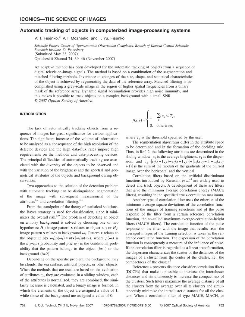
Figure 1 shows the variation r�x ,y� from the position ofthe center of the reference array �x ,y� in the search zonewhen the image of an ellipse on a homogeneous background�Figs. 1a and 1b� and the actual grey-scale image of a boat�Figs. 1c and 1d� are used as references. Figures 1a and 1bshow the variation of the form of the correlation surface asthe object rotates relative to the reference. The matched-filtering measures decrease both when the object rotates�from 7.98 to 2.337 for the PSR and from 0.958 to 0.25 forS� �Figs. 1a and 1b�, and when the brightness characteristicsof the object and background and the geometrical character-istics of the object change �PSR=5.34 and S=0.98 in Fig. 1c,and PSR=3.89 and S=0.53 in Fig. 1d�. The change of theclassification measure is mainly caused by the change of thegeometrical properties of the object and by the influence ofthe background. The PSR classification measure describesthe character of the surface but does not make it possible toestablish the threshold value for estimating the minimum“correlation” surface. Its value changes substantially, de-pending on the brightness and other characteristics of theobject and background. In order to form a single qualitycriterion, we shall use the similarity characteristic of thesharpness of the minimum of the surface r�x ,y� in the cur-rent frame to the sharpness of the minimum in the frame of
753Fisenko et al.
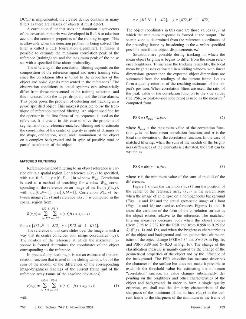
the reference array for two coordinate directions in accor-dance with Eqs. �4� �see Fig. 2�.
�4�where �= ��x ,�y� is the displacement along the coordinateaxes from the center �x0 ,y0� of the object or the reference, �and �ref are the minimum values of r�x ,y� for the current andthe reference arrays, rmax and rmax ref are the maximum val-ues of r�x ,y� for the current and the reference arrays, andT= �Tx ,Ty� are the threshold values.
The classification measure is S=min�Sx ,Sy�. The intro-duction of measure S makes it possible to establish a singlethreshold for a series of observations. Regeneration of thereference array breaks up a sequence of images into groupsof locally quasi-steady-state sequences, and this can be com-pared to normalization of the attributes to ensure that theyare invariant to a scale change of the object and to projectiveand affine transformations.
FIG. 1. Graphs of the r�x ,y� dependence as the object rotates relative to a rbackground and the geometrical characteristics of the object vary �c� and �d
FIG. 2. Graphs of the dependence of the normalized sum of the moduli ofthe brightness differences r /rmax for the reference array �a� and for thecurrent search window W �b�.
754 J. Opt. Technol. 74 �11�, November 2007
INCREASING THE OBJECT-DETECTION EFFICIENCYBY USING INFORMATION IN THE REGION OF HIGH SPATIALFREQUENCIES
It follows from the results of the modelling presentedhere that measure S is substantially degraded on a complexbackground. Matched filtering must be carried out not in theentire window Wref but only at the boundaries of the object.The region of high spatial frequencies presents some ap-proximation to this filtering. Actually, each observed objectis limited in space, and, when the size of the object is deter-mined, the sites where the individual nodes are joined thatform lines on the image become discernable. This makes itpossible to carry out preliminary segmentation of an imagesubjected to differential processing methods. At present, onewidely used method is Kenny’s method,11 which smoothesthe image, and then forms extended contour segments fromadjacent image elements that have large values of the modu-lus of the gradient along the direction of the gradient.
To increase the reliability of the matched filtering, it isnecessary to fill the region inside the contour in the binaryimage thus formed. However, it is possible to form the mostinformative region by simpler methods. For example, weshall use as a differential operator a modified Sobel operatorwhose masks have the form
− 1 − 2 − 1
0 0 0
1 2 1 and − 1 0 1
− 2 0 2
− 1 0 1 ,
while the output value is computed as the sum of the moduliof the horizontal and vertical gradients.
After differentiation, threshold limitation is carried outusing threshold Tb, and a binary image is formed
fbin�x,y� = �1, fSob � Tb, �x,y� � �b
2, fSob � Tb, �x,y� � �back� for �x,y� � W ,
�5�
where �b is the region of high spatial frequencies �containsthe boundaries of the object� in the window, and � is the
ce �a� and �b� and as the brightness characteristics of the objective and the
eferen�.back
754Fisenko et al.
ks of
region of low spatial frequencies �contains the background�.Since the object’s shape changes from frame to frame, it
is necessary to expand the region �b to increase the reliabil-ity of the estimate. Instead of filling the contours, the regionof high spatial frequencies can be expanded by using binarydilatation for all �k , l��W,
fd�k,l� = max�x,y��Wd
�fbin�x,y�� , �6�
where Wd is the sliding dilatation window.A binary image is next formed in window Wb. Matched
filtering will be carried out in accordance with Eq. �7�, andnot Eq. �1�:
r�x,y� = �t��b ref
�s��b ref
���s,t� − f�x + s,y + t�� �7�
with x� �J /2 ,N−1−J /2�, y� �K /2 ,M −1−K /2�, where�b,ref is the binary region �mask� corresponding to the refer-ence.
The action of the background on the estimate is reducedby using a binary mask of the reference array. The SNR isincreased by several decibels for the same sequence offrames when an object is tracked, neglecting informationconcerning the higher spatial frequencies of the image andtaking them into account.
FORMING AN ADAPTIVE FILTERING WINDOW
During tracking, an object changes its geometricalcharacteristics—i.e., its size and shape. To enhance the track-ing stability, the size of the reference-array window needs tobe adaptively varied. Estimating the size of the binary regioncauses no difficulties when there is no high-frequency noisein window Wb. However, when an object is observed on acomplex background, a technique must be used that makes itpossible to determine the boundaries of the region withoutallowing the region of interest to broaden because of noise.On one hand, when the reference array is regenerated, thepossible size of the reference-array window can be increased;on the other hand, binary regions of noise can fall into theregion in this case, causing it to be broadened.
For example, when the reference array is regenerated insequences of the displacement of an object on the back-ground of a shoreline, the shoreline regions can produce un-founded expansion of the boundaries of the reference array.
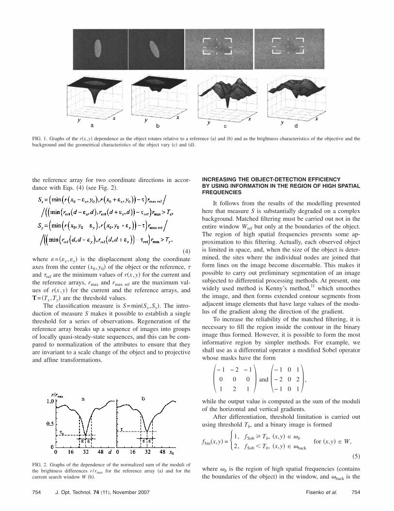
FIG. 3. Variation of the size of the reference array and of binary mas
755 J. Opt. Technol. 74 �11�, November 2007
One method is to form two zones relative to the new positionof the reference array: an expansion zone �which surroundsthe reference-array window with a rectangle whose sides ex-ceed the size of the reference by ±dexp� and a protection zone�bounded by a rectangle whose sides exceed the size of thereference by ±2dexp�. If the binary region extends beyond theboundaries of the expansion region into the protection zone,the size of the reference array is not increased in this direc-tion. The dynamic accumulation region is the largest of thethree regions: the region of the reference array, the region ofpossible increase of the object when the reference array isregenerated, and the protection region.
Examples of binary masks of an object that correspondto the reference array of an aircraft that changes its sizeduring movement are shown in Fig. 3. This figure showsmagnified fragments of the frames of the image sequencewhen the object is being tracked �a�, magnified fragments ofthe tracked object with markers designating the object �b�,and examples of a grey-scale reference array and of a binarymask of the reference array for the corresponding frames ofthe sequence �c�. The size of the matched-filtering windowvaries in accordance with the shape change of the trackedobject. The size of the masks of the reference array changesfrom 1513 image elements in the first frame to 4941elements in the fourth frame of the sequence shown in thefigure. The binary masks corresponding to the reference ar-rays clearly demonstrate the correspondence of the compari-son region when matched filtering of the shape of the objectis carried out.
DYNAMIC SIGNAL ACCUMULATION
As is well known, when an image is differentiated, thenoise increases. To best form the contour, dynamic accumu-lation of the grey-scale image signal is carried out12 in theregion of dynamic accumulation. When the reference array isregenerated, a grey-scale image is chosen from the currentframe, while a binary image is formed from the dynamicallyaccumulated image. In this case, the process of dynamic ac-cumulation is controlled in each frame in accordance withthe quality of the accumulated matched filtering. Since thequality of the filtering depends both on the change of shapeof the object and on the background on which the object isobserved, two thresholds are established. The first thresholdis for regeneration of the reference array, and the second,
the object that correspond to the references. See text for explanation.
755Fisenko et al.
lower one is to prevent dynamic accumulation in the currentframe. Such control makes it possible to find a compromisebetween making a decision concerning regeneration of thereference array and changing the reference in connectionwith the change of the shape and size of the object. More-over, since a binary array is formed from a dynamically ac-cumulated array, only part of the noise can form a binaryregion corresponding to a new reference array.
DESCRIPTION OF THE METHOD
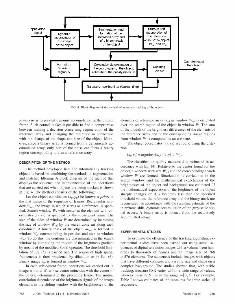
The method developed here for automatically trackingobjects is based on combining the methods of segmentationand matched filtering. A block diagram of the method thatdisplays the sequence and interconnection of the operationsthat are carried out when objects are being tracked is shownin Fig. 4. The method consists of the following:
Let the object coordinates �x0 ,y0� be known a priori inthe first image of the sequence of frames. Rectangular win-dow Wref, the image in which serves as a reference, is speci-fied. Search window W, with center at the element with co-ordinates �x0 ,y0�, is specified for the subsequent frame. Thesize of the sides of window W are determined by increasingthe size of window Wref by the search zone ±d along eachcoordinate. A binary mask of the object �bref is formed inwindow Wb, corresponding in position and size to windowWref. To do this, the contours are discriminated in the searchwindow by computing the moduli of the brightness gradientby means of the modified Sobel operator. The threshold limi-tation of Eq. �5� is carried out. The region of high spatialfrequencies is then broadened by dilatation as in Eq. �6�.Binary image �b is formed in window Wb.
In each subsequent frame, operations are carried out inimage window W, whose center coincides with the center ofthe object, determined in the preceding frame. The mutualcorrelation dependence of the brightness signals of the imageelements in the sliding window with the brightnesses of the
FIG. 4. Block diagram of the meth
756 J. Opt. Technol. 74 �11�, November 2007
elements of reference array �ref in window Wref is estimatedover the search region of the object in window W. The sumof the moduli of the brightness differences of the elements ofthe reference array and of the corresponding image regionsfrom window W is computed as an estimate.
The object coordinates �x0 ,y0� are found using the crite-rion
�x0,y0� = argmin�r�x,y���x,y� � W� .
The classification-quality measure S is estimated in ac-cordance with Eq. �4�. Relative to the center found for theobject, a window with size Wref and the corresponding searchwindow W are formed. Binarization is carried out in thesearch window, and the mathematical expectations of thebrightnesses of the object and background are estimated. Ifthe mathematical expectation of the brightness of the objectsharply changes or if S becomes less than the specifiedthreshold values, the reference array and the binary mask areregenerated. In accordance with the resulting estimate of theinterframe shift, dynamic accumulation of the grey-scale sig-nal occurs. A binary array is formed from the recursivelyaccumulated image.
EXPERIMENTAL STUDIES
To estimate the efficiency of the tracking algorithm, ex-perimental studies have been carried out using actual se-quences of digital television images with a volume from hun-dreds to thousands of frames and an image size of 768576 elements. The sequences include images with objectsthat have different contrasts and varying size and shape on acomplex background. The studies showed that, with stabletracking, measure PSR varies within a wide range of values,whereas measure S lies in the range �0,1�. For example,Table I shows estimates of the measures for three series ofsequences.
f automatic tracking of the object.
od o756Fisenko et al.
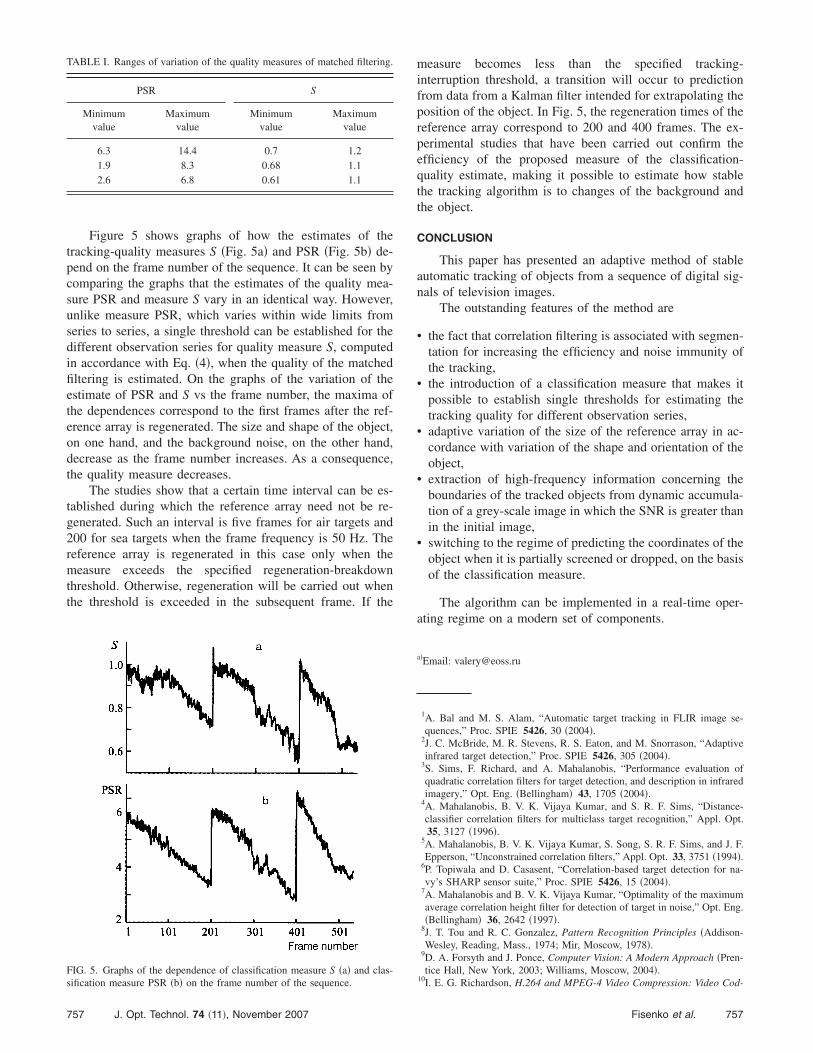
Figure 5 shows graphs of how the estimates of thetracking-quality measures S �Fig. 5a� and PSR �Fig. 5b� de-pend on the frame number of the sequence. It can be seen bycomparing the graphs that the estimates of the quality mea-sure PSR and measure S vary in an identical way. However,unlike measure PSR, which varies within wide limits fromseries to series, a single threshold can be established for thedifferent observation series for quality measure S, computedin accordance with Eq. �4�, when the quality of the matchedfiltering is estimated. On the graphs of the variation of theestimate of PSR and S vs the frame number, the maxima ofthe dependences correspond to the first frames after the ref-erence array is regenerated. The size and shape of the object,on one hand, and the background noise, on the other hand,decrease as the frame number increases. As a consequence,the quality measure decreases.
The studies show that a certain time interval can be es-tablished during which the reference array need not be re-generated. Such an interval is five frames for air targets and200 for sea targets when the frame frequency is 50 Hz. Thereference array is regenerated in this case only when themeasure exceeds the specified regeneration-breakdownthreshold. Otherwise, regeneration will be carried out whenthe threshold is exceeded in the subsequent frame. If the
TABLE I. Ranges of variation of the quality measures of matched filtering.
PSR S
Minimumvalue
Maximumvalue
Minimumvalue
Maximumvalue
6.3 14.4 0.7 1.21.9 8.3 0.68 1.12.6 6.8 0.61 1.1
FIG. 5. Graphs of the dependence of classification measure S �a� and clas-sification measure PSR �b� on the frame number of the sequence.
757 J. Opt. Technol. 74 �11�, November 2007
measure becomes less than the specified tracking-interruption threshold, a transition will occur to predictionfrom data from a Kalman filter intended for extrapolating theposition of the object. In Fig. 5, the regeneration times of thereference array correspond to 200 and 400 frames. The ex-perimental studies that have been carried out confirm theefficiency of the proposed measure of the classification-quality estimate, making it possible to estimate how stablethe tracking algorithm is to changes of the background andthe object.
CONCLUSION
This paper has presented an adaptive method of stableautomatic tracking of objects from a sequence of digital sig-nals of television images.
The outstanding features of the method are
• the fact that correlation filtering is associated with segmen-tation for increasing the efficiency and noise immunity ofthe tracking,
• the introduction of a classification measure that makes itpossible to establish single thresholds for estimating thetracking quality for different observation series,
• adaptive variation of the size of the reference array in ac-cordance with variation of the shape and orientation of theobject,
• extraction of high-frequency information concerning theboundaries of the tracked objects from dynamic accumula-tion of a grey-scale image in which the SNR is greater thanin the initial image,
• switching to the regime of predicting the coordinates of theobject when it is partially screened or dropped, on the basisof the classification measure.
The algorithm can be implemented in a real-time oper-ating regime on a modern set of components.
a�Email: [email protected]
1A. Bal and M. S. Alam, “Automatic target tracking in FLIR image se-quences,” Proc. SPIE 5426, 30 �2004�.
2J. C. McBride, M. R. Stevens, R. S. Eaton, and M. Snorrason, “Adaptiveinfrared target detection,” Proc. SPIE 5426, 305 �2004�.
3S. Sims, F. Richard, and A. Mahalanobis, “Performance evaluation ofquadratic correlation filters for target detection, and description in infraredimagery,” Opt. Eng. �Bellingham� 43, 1705 �2004�.
4A. Mahalanobis, B. V. K. Vijaya Kumar, and S. R. F. Sims, “Distance-classifier correlation filters for multiclass target recognition,” Appl. Opt.35, 3127 �1996�.
5A. Mahalanobis, B. V. K. Vijaya Kumar, S. Song, S. R. F. Sims, and J. F.Epperson, “Unconstrained correlation filters,” Appl. Opt. 33, 3751 �1994�.
6P. Topiwala and D. Casasent, “Correlation-based target detection for na-vy’s SHARP sensor suite,” Proc. SPIE 5426, 15 �2004�.
7A. Mahalanobis and B. V. K. Vijaya Kumar, “Optimality of the maximumaverage correlation height filter for detection of target in noise,” Opt. Eng.�Bellingham� 36, 2642 �1997�.
8J. T. Tou and R. C. Gonzalez, Pattern Recognition Principles �Addison-Wesley, Reading, Mass., 1974; Mir, Moscow, 1978�.
9D. A. Forsyth and J. Ponce, Computer Vision: A Modern Approach �Pren-tice Hall, New York, 2003; Williams, Moscow, 2004�.
10I. E. G. Richardson, H.264 and MPEG-4 Video Compression: Video Cod-
757Fisenko et al.

ing for Next Generation Multimedia �Wiley, Chichester, 2003; Tekhnos-fera, Moscow, 2005�.
11L. Shapiro and G. Stockman, Computer Vision �Prentice Hall, New York,2001; BINOM, Moscow, 2006�.
758 J. Opt. Technol. 74 �11�, November 2007
12V. T. Fissenko, V. I. Mojeiko, and V. N. Zelentsov, “Dynamic accumula-tion technique increases the underwater viewing distance,” in Proceedingsof the International Conference on Current Problems in Optical of NaturalWaters, St. Petersburg, Russia. 2001, September, pp. 119–121.
758Fisenko et al.