av3 - mecvel srl
TRANSCRIPT

edizione - edition
06/2013123
AV3Modello AV3
• Motore A.C.Forma B 14 CE• Riduttore vite senza fine-ruota elicoidale• Stelo filettato trapezoidale o a ricircolo di sfere (VRS)• Asta traslante in acciaio cromato• Lubrificazione a grasso• IP 50 / IP 65, testato secondo norma CEI EN 60529• Temperatura di funzionamento -10°C +60°C• Impiego intermittente S3 30% (5 min) a 30°C(*)
• Fine corsa• Potenziometro ed encoder a richiesta
(*) Per impieghi diversi contattare il Ns. Ufficio Tecnico
Model AV3
• A.C. motor, flange B14 - CE• Worm gearbox• Acme lead screw or ballscrew (VRS)• Chrome plated steel push rod• Grease Lubricated• IP 50 / IP 65, tested according to rule CEI EN 60529• Working temperature range -10°C +60°C• Intermittent duty S3 30% (5 min) a 30°C(*)
• Limit switches• Potentiometer and encoder on request
(*) For any special duty please contact our technical dept.
Nota:
questo attuatore è sempre dotato di finecorsa integratoNote:
this actuator always comes with integrated stroke limit device
AV3 (Vac)
Fmax
Fmax
Velocità
Speed
Versione
Version
Taglia motore
Motor size
Potenza motore
Motor power
Giri motore
Motor speed
Rapporti Riduzione
Gearbox Reduction Ratio
D vite
Screw D
Passo
Pitch
Rendimento
Efficiency
Corsa max (mm)Max stroke [mm]
(N) (mm/s) (KW) (rpm) (mm) (mm) AV3-F AV3
13000 55 M01 IEC90 3.00 2800 1:10 30 12 0.24 1080 108020000 30 M02 IEC90 3.00 2800 1:10 30 6 0.19 870 87025000 20 M03 IEC80 1.80 2800 1:30 30 12 0.23 780 78025000 10 M04 IEC80 1.10 1400 1:30 30 12 0.23 780 78025000 5 M05 IEC80 0.75 1400 1:30 30 6 0.18 780 780
AV3 VRS (ballscrew) (Vac)
Fmax
Fmax
Velocità
Speed
Versione
Version
Taglia motore
Motor size
Potenza motore
Motor power
Giri motore
Motor speed
Rapporti Riduzione
Gearbox Reduction Ratio
D vite
Screw D
Passo
Pitch
Rendimento
Efficiency
Corsa max (mm)Max stroke [mm]
(N) (mm/s) (KW) (rpm) (mm) (mm) AV3-VRS-F AV3-VRS
8000 45 M01 IEC80 0.75 2800 1:10 25 10 0.56 980 98013000 22 M02 IEC80 0.55 1400 1:10 25 10 0.56 770 77025000 15 M03 IEC80 0.75 2800 1:30 25 10 0.54 555 55525000 7 M04 IEC80 0.55 1400 1:30 25 10 0.54 555 555

edizione - edition
06/2013124
AV3
GR. / SIZE
DIMENSIONI MOTORI C.A. / A.C. MOTORS DIMENSIONS
Autofrenante / Brake motors
Autofrenante / Brake motors
VERSIONE / TYPE
90
Standard
Standard
80
P
251
220
182344
296
238
280
H K Ø
165
Ø20 +0.1 0
25
Ø20 +0.1 0
188
86
43
4854
285 + corsa/stroke
116.5
Ø40
18
Ø65
P
168.5 + corsa/stroke 450
100
136.
5
31.5
K
H
Ø45
Ø
46
40
5352
114.5
128.
510
2
Ø20 +0.1 0
25
Ø20+0.1 0
188
86
43
4854
305 + corsa/stroke
116.5
Ø40
18
Ø65
220
188.5 + corsa/stroke 450
100
136.
5
31.5
29623
8
Ø45
Ø165
46
40
5352
114.5
128.
510
2
AV3
AV3 VRS (ballscrew)
ATTUATORE CON FINE CORSA INTEGRATO / ACTUATOR WITH INTEGRATED LIMIT SWITCHES
ATTUATORE CON STELO RICIRCOLO DI SFERE VRS CON FINE CORSA
BALLSCREW ACTUATOR WITH LIMIT SWITCHES
edizione - edition
06/2013125
AV3
AR0 (Standard) AR1
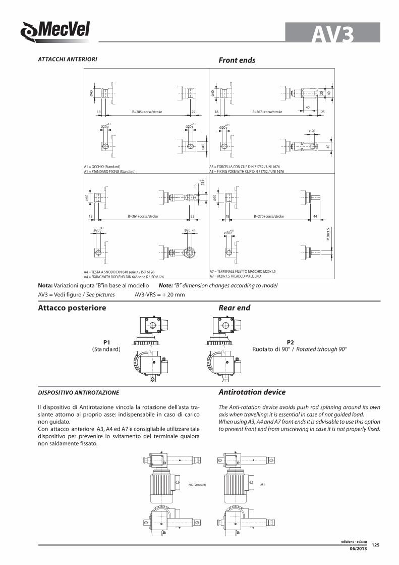
ATTACCHI ANTERIORI Front ends
B=364+corsa/stroke
Ø40
Ø20+0.1 0
18
Ø20 H7
25 0 -0
.1
18
25
B=285+corsa/stroke
Ø20+0.1 0
18
Ø40
Ø45
Ø20+0.1 0
25
B=270+corsa/stroke
Ø20+0.1 0
18Ø
40
M20
x1.5
44
B=367+corsa/stroke
Ø20+0.1 0
18
Ø40 40
40
20
40
Ø20
25
A4 = TESTA A SNODO DIN 648 serie K / ISO 6126A4 = FIXING WITH ROD END DIN 648 serie K / ISO 6126
A1 = OCCHIO (Standard)A1 = STANDARD FIXING (Standard)
A7 = TERMINALE FILETTO MASCHIO M20x1.5A7 = M20x1.5 TREADED MALE END
A3 = FORCELLA CON CLIP DIN 71752 / UNI 1676A3 = FIXING YOKE WITH CLIP DIN 71752 / UNI 1676
Nota: Variazioni quota “B”in base al modello Note: “B” dimension changes according to model
AV3 = Vedi figure / See pictures AV3-VRS = + 20 mm
Attacco posteriore Rear end
P1 P2/°09idotatouR)dradnatS( Rotated trhough 90°
DISPOSITIVO ANTIROTAZIONE
Il dispositivo di Antirotazione vincola la rotazione dell’asta tra-slante attorno al proprio asse: indispensabile in caso di carico non guidato. Con attacco anteriore A3, A4 ed A7 è consigliabile utilizzare tale dispositivo per prevenire lo svitamento del terminale qualora non saldamente fissato.
Antirotation device
The Anti-rotation device avoids push rod spinning around its own axis when travelling: it is essential in case of not guided load. When using A3, A4 and A7 front ends it is advisable to use this option to prevent front end from unscrewing in case it is not properly fixed.
edizione - edition
06/2013126
AV3DISPOSITIVI CONTROLLO CORSA
ELETTRICI / ELETTRONICIElectric / Electronic
Stroke Control Devices
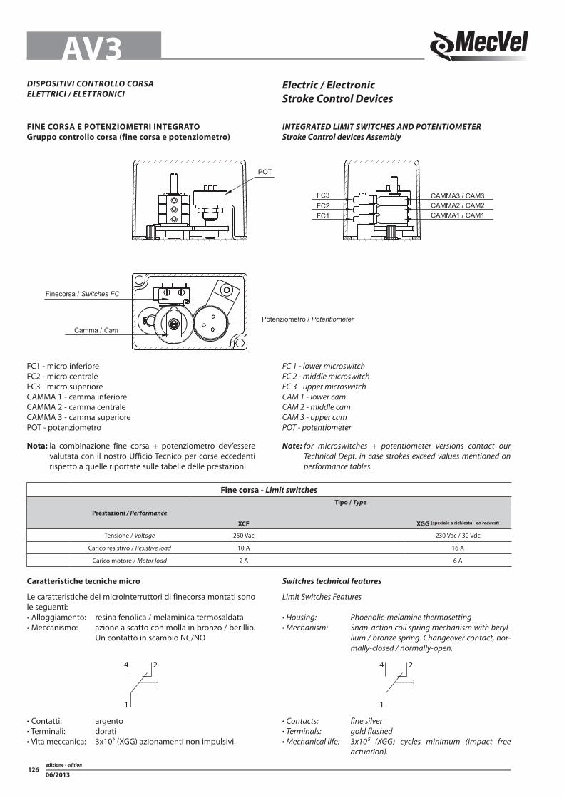
Caratteristiche tecniche micro
Le caratteristiche dei microinterruttori di finecorsa montati sono le seguenti:• Alloggiamento: resina fenolica / melaminica termosaldata• Meccanismo: azione a scatto con molla in bronzo / berillio.
Un contatto in scambio NC/NO
Switches technical features
Limit Switches Features
• Housing: Phoenolic-melamine thermosetting• Mechanism: Snap-action coil spring mechanism with beryl-
lium / bronze spring. Changeover contact, nor-mally-closed / normally-open.
4
1
2 4
1
2
• Contatti: argento• Terminali: dorati• Vita meccanica: 3x10⁵ (XGG) azionamenti non impulsivi.
• Contacts: fine silver• Terminals: gold flashed• Mechanical life: 3x10⁵ (XGG) cycles minimum (impact free
actuation).
CAMMA3 / CAM3
Camma / Cam
Finecorsa / Switches FC
Potenziometro / Potentiometer
CAMMA2 / CAM2CAMMA1 / CAM1
POT
FC3FC2FC1
FC1 - micro inferioreFC2 - micro centraleFC3 - micro superioreCAMMA 1 - camma inferioreCAMMA 2 - camma centraleCAMMA 3 - camma superiorePOT - potenziometro
Nota: la combinazione fine corsa + potenziometro dev’essere valutata con il nostro Ufficio Tecnico per corse eccedenti rispetto a quelle riportate sulle tabelle delle prestazioni
FC 1 - lower microswitchFC 2 - middle microswitchFC 3 - upper microswitchCAM 1 - lower camCAM 2 - middle camCAM 3 - upper camPOT - potentiometer
Note: for microswitches + potentiometer versions contact our Technical Dept. in case strokes exceed values mentioned on performance tables.
FINE CORSA E POTENZIOMETRI INTEGRATO
Gruppo controllo corsa (fine corsa e potenziometro)
INTEGRATED LIMIT SWITCHES AND POTENTIOMETER
Stroke Control devices Assembly
Fine corsa - Limit switches
Tipo / Type
Prestazioni / Performance
XCF XGG (speciale a richiesta - on request)
Tensione / Voltage 250 Vac 230 Vac / 30 Vdc
Carico resistivo / Resistive load 10 A 16 A
Carico motore / Motor load 2 A 6 A

edizione - edition
06/2013127
AV3
ORIENTAMENTO MORSETTIERA E-BOX POSITION
4321 (Standard)
MOTOR AND LIMIT SWITCHES POSITION
M1-FC1(Standard)
M2-FC2 M2-FC3M1-FC2
1 2 3
90.0°
R4.5
3.29.3
1
2
3 Ø22
.2
SIMBOLO / SYMBOL
A Versione / Version60°
CW
Ø 0.500(12.70)
BC
1
2
3
1
2
3
SIMBOLO / SYMBOL
±0.015
1.31
2(3
3.32
)
0.015(4.75)
0.625(15.88)
±0.0
15
±0.015 ±0.015B Versione / Version
ORIENTAMENTO MOTORE E FINE CORSA
Potenziometro rotativo - Spinning potentiometer
Prestazioni / Performances Tipo / Type (A) Tipo / Type (A)
Angolo max. di lavoro / Max. angle 340° ± 3° 352° ± 2°Resistenza Ohm / Resistance 1K / 5K / 10K (standard) 1K / 5K / 10K (standard)
Alimentazione consigliata / Voltage MAX 10 V MAX 50 VLinearità indipendente / Indipendent linearity ± 2% ± 1%
Tolleranza / Tolerance ± 20% ± 3%Coefficente deriva termica / Temperature coefficient of resistance 600 ppm / °C 20 ppm / °C
edizione - edition
06/2013128
AV3
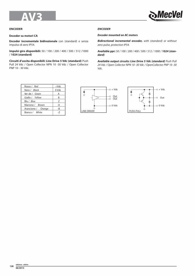
+ Vdc
0 Vdc
LINE DRIVER
OutOut
+ Vdc
0 Vdc
PUSH-PULL
Out
Rosso / Red ÷VdcNero / Black 0 VdcVer de / Green AGiallo / Yellow BBlu / Blue ZMarrone / Brown -AArancione / Orange -BBianco / White -Z
ENCODER
Encoder su motori CA
Encoder incrementale bidirezionale con (standard) e senza impulso di zero IP54.
Impulsi giro disponibili: 50 / 100 / 200 / 400 / 500 / 512 /1000 / 1024 (standard)
Circuiti d’uscita disponibili: Line Drive 5 Vdc (standard) Push Pull 24 Vdc / Open Collector NPN 10 -30 Vdc / Open Collector PNP 10 - 30 Vdc.
ENCODER
Encoder mounted on AC motors
Bidirectional incremental encoder, with (standard) or without zero-pulse, protection IP54.
Available ppr: 50 / 100 / 200 / 400 / 500 / 512 / 1000 / 1024 (stan-
dard)
Available output circuits: Line Drive 5 Vdc (standard) Push Pull 24 Vdc / Open Collector NPN 10 -30 Vdc / OpenCollector PNP 10 -30 Vdc.

edizione - edition
06/2013129
AV3RIFERIMENTO SIGLA D’ORDINAZIONE
Fine Corsa Meccanici:
2FC2 = 2 Micro XGG3FC2 = 3 Micro XGG
Potenziometri:
POT01A = 1 k OhmPOT05A = 5 k OhmPOT10A = 10 k Ohm(versioni standard)
POT01B = 1 k OhmPOT05B = 5 k OhmPOT10B = 10 k Ohm(versioni speciali)
Encoder:
(solo su motore CA)E05 = Push Pull 1024 pprE06 = Line Drive 1024 ppr (standard) E07 = Open Collector NPNE08 = Open Collector PNP
(solo su cassa attuatore)E00 = Push Pull 2 canali 4 ppr E09 = Push Pull 1024 pprE10 = Line Drive 1024 pprE11 = Open Collector NPNE12 = Open Collector PNP
E13 = Encoder non contemplato (secondo richiesta cliente)
ORDERING KEY REFERENCES
Mechanical limit switches:
2FC2 = 2 Micro XGG3FC2 = 3 Micro XGG
Potentiometers:
POT01A = 1 k OhmPOT05A = 5 k OhmPOT10A = 10 k Ohm(standard version)
POT01B = 1 k OhmPOT05B = 5 k OhmPOT10B = 10 k Ohm(standard version)
Encoder:
(only on AC motor)E05 = Push Pull 1024 pprE06 = Line Drive 1024 ppr (standard) E07 = Open Collector NPNE08 = Open Collector PNP
(only on actuator housing)E00 = Push Pull 2 channels 4 ppr E09 = Push Pull 1024 pprE10 = Line Drive 1024 pprE11 = Open Collector NPNE12 = Open Collector PNP
E13 = Encoder not considered above (according to customer request)

edizione - edition
06/2013130
AV3GUIDA ALLA SCELTA DELLA MOTORIZZAZIONE - Motor choice guideline
TIPO MOTORE / MOTOR TYPE
Versione / Version: CA = corrente alternata / AC = alternate current PD = PAM a disegno / Special motorflange (provide drawing)
Tensione / Voltage: CA / AC = 230/400/50 – 190/330/50 – 208/360/50 – 400/690/50 277/480/60 – 220/380/60 – 254/440/60 – 480/830/60 MT = Multitensione / Multivoltage 230/50 (monofase / 1-phase)
Tipo / Type: T = trifase / 3-phase(Solo per CA / only for AC M = monofase / 1-phase AT = trifase autofrenante / 3-phase with brake AM = monofase autofrenante / 1-phase with brake ME = monofase con condensatore elettronico / 1-phase whit starting capacitor AE = monofase autofr. con condensatore elettronico / 1-phase with brake and starting capacitor
Grandezza / Size: CA / AC: IEC 80/90
N°Poli / Pole: CA / AC: 2 / 4 / 6
VARIANTI MOTORE CA / AC MOTOR OPTIONS
Flangia tipo / Motorflange type: PAM80B14
Tipo servizio / Service rate: S1 / S2 / S3
Classe isolamento / Insulation class: F = standard (non indicare)/ standard (leave blank) Specificare solo se diversa / Advise only if different than “F”
Grado Protezione / Protection Degree: IP55 (non indicare / leave blank) IP65
TP = tropicalizzato / tropicalization ALTRO / OTHER = specificare / advise
Potenza CA / AC Power: kW
kW trifase / 3-phase kW monofase / 1-phase
IEC 2POLI/POLE 4POLI/POLE 6POLI/POLE 2POLI/POLE 4POLI/POLE 6POLI/POLE
80 0,75-1,1-1,5-1,8 0,55-0,75-0,88-1,1 0,37-0,55-0,75 0,75-1,1-1,5 0,55-0,75-0,88 0,37-0,45
90 1,5-2,2-3 1,1-1,5-1,8 0,75-1,1-1,5 1,5-1,8-2,2 1,1-1,5-1,8 0,55-0,75

edizione - edition
06/2013131
AV3
Freno / Brake: FECC = freno elettromagnetico negativo in CC / DC brake negative action (standard)
Tensione di alimentazione 230V± 10% 50/60Hz dal lato A.C. dell’alimentatore freno. Il freno viene alimentato direttamente dall’alimentazione del motore. (standard) Sono disponibili a richiesta motori con freni con alimentazione separata e con tensioni nel range (24-205 Vdc) In questo caso il freno necessita di una alimentazione separata da quella del motore. In questo caso la sigla diventa FECC-AS-24Vdc
Power Supply 230V±10% 50/60Hz AC side inside the brake. The brake is powered directly from the power supply of the motor (standard) Motors with separated brake power supply and tensions in the range (24-205 Vdc) can be available on request. In this case the brake needs a separated power supply from the motor and its code becomes FECC-AS-24 Vdc
FECA= freno elettromagnetico in CA / AC brake Tensione di alimentazione 230/400V± 10% 50/60Hz. Il freno viene alimentato direttamente dall’alimentazione del motore. Sono disponibili a richiesta motori con freni con alimentazione separata e con tensioni nel range (24-690 Vac) 50/60 HZ In questo caso il freno necessita di una alimentazione separata da quella del motore. In questo caso la sigla diventa FECA-AS-230 Vac 50 HZ
Power Supply 230/400V±10% 50/60Hz. The brake is powered directly from the power supply of the motor. Motors with separated brake power supply and tensions in the range (24-690 Vac - 50/60 Hz) can be available on request. In this case the brake needs a separated power supply from the motor and its code becomes FECA-AS-230 Vac 50 HZ
Alimentazione separata del freno / Separate brake power supply: si ottiene tramite una morsettiera ausiliaria, con fissati i morsetti delle bobine freno, posizionata all’interno del coprimorsettiera motore. achieved by means of an auxiliary terminal board, with fixed brake coil terminals, located inside the motor terminal box.
Nb. Per tutti i motori predisposti inverter il freno deve avere senpre l’alimentazione separata Nb. On all motors prepared for frequency converter the brake must always have a separate power supply
SENZA = omettere / NO BRAKE = leave blank
Opzioni / Options: LS = leva sblocco / hand release lever (non indicare / leave blank) Nota: = non disponibile per motori IEC 50 IEC 56 / NOTE: not available for motor IEC 50 IEC 56
AB = albero bisporgente / 2’shaft IN = avvolgimento per inverter / winding for inverters ALTRO / OTHER = indicare per esteso / advise SENZA / NONE = omettere / leave blank

edizione - edition
06/2013132
NOTE NOTES
edizione - edition
06/2013133
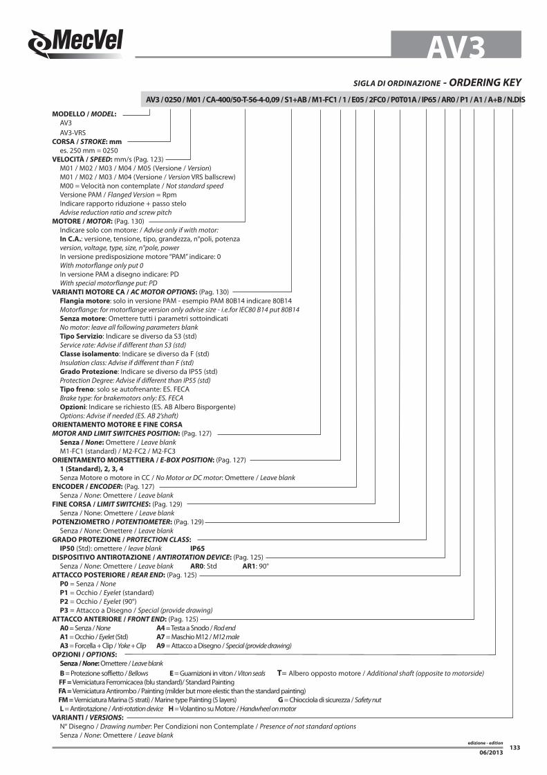
AV3SIGLA DI ORDINAZIONE - ORDERING KEY
AV3 / 0250 / M01 / CA-400/50-T-56-4-0,09 / S1+AB / M1-FC1 / 1 / E05 / 2FC0 / P0T01A / IP65 / AR0 / P1 / A1 / A+B / N.DIS
MODELLO / MODEL:
AV3 AV3-VRSCORSA / STROKE: mm
es. 250 mm = 0250VELOCITÀ / SPEED: mm/s (Pag. 123) M01 / M02 / M03 / M04 / M05 (Versione / Version) M01 / M02 / M03 / M04 (Versione / Version VRS ballscrew) M00 = Velocità non contemplate / Not standard speed Versione PAM / Flanged Version = Rpm Indicare rapporto riduzione + passo stelo Advise reduction ratio and screw pitchMOTORE / MOTOR: (Pag. 130) Indicare solo con motore: / Advise only if with motor: In C.A.: versione, tensione, tipo, grandezza, n°poli, potenza version, voltage, type, size, n°pole, power In versione predisposizione motore “PAM” indicare: 0 With motorflange only put 0 In versione PAM a disegno indicare: PD With special motorflange put: PDVARIANTI MOTORE CA / AC MOTOR OPTIONS: (Pag. 130) Flangia motore: solo in versione PAM - esempio PAM 80B14 indicare 80B14 Motorflange: for motorflange version only advise size - i.e.for IEC80 B14 put 80B14 Senza motore: Omettere tutti i parametri sottoindicati No motor: leave all following parameters blank Tipo Servizio: Indicare se diverso da S3 (std) Service rate: Advise if different than S3 (std) Classe isolamento: Indicare se diverso da F (std) Insulation class: Advise if different than F (std) Grado Protezione: Indicare se diverso da IP55 (std) Protection Degree: Advise if different than IP55 (std) Tipo freno: solo se autofrenante: ES. FECA Brake type: for brakemotors only: ES. FECA Opzioni: Indicare se richiesto (ES. AB Albero Bisporgente) Options: Advise if needed (ES. AB 2’shaft)ORIENTAMENTO MOTORE E FINE CORSA
MOTOR AND LIMIT SWITCHES POSITION: (Pag. 127) Senza / None: Omettere / Leave blank M1-FC1 (standard) / M2-FC2 / M2-FC3ORIENTAMENTO MORSETTIERA / E-BOX POSITION: (Pag. 127) 1 (Standard), 2, 3, 4
Senza Motore o motore in CC / No Motor or DC motor: Omettere / Leave blankENCODER / ENCODER: (Pag. 127) Senza / None: Omettere / Leave blankFINE CORSA / LIMIT SWITCHES: (Pag. 129) Senza / None: Omettere / Leave blankPOTENZIOMETRO / POTENTIOMETER: (Pag. 129) Senza / None: Omettere / Leave blankGRADO PROTEZIONE / PROTECTION CLASS:
IP50 (Std): omettere / leave blank IP65
DISPOSITIVO ANTIROTAZIONE / ANTIROTATION DEVICE: (Pag. 125) Senza / None: Omettere / Leave blank AR0: Std AR1: 90°ATTACCO POSTERIORE / REAR END: (Pag. 125) P0 = Senza / None P1 = Occhio / Eyelet (standard) P2 = Occhio / Eyelet (90°) P3 = Attacco a Disegno / Special (provide drawing)ATTACCO ANTERIORE / FRONT END: (Pag. 125) A0 = Senza / None A4 = Testa a Snodo / Rod end A1 = Occhio / Eyelet (Std) A7 = Maschio M12 / M12 male A3 = Forcella + Clip / Yoke + Clip A9 = Attacco a Disegno / Special (provide drawing)OPZIONI / OPTIONS:
Senza / None: Omettere / Leave blank B = Protezione soffietto / Bellows E = Guarnizioni in viton / Viton seals T= Albero opposto motore / Additional shaft (opposite to motorside) FF = Verniciatura Ferromicacea (blu standard)/ Standard Painting
FA = Verniciatura Antirombo / Painting (milder but more elestic than the standard painting) FM = Verniciatura Marina (5 strati) / Marine type Painting (5 layers) G = Chiocciola di sicurezza / Safety nut L = Antirotazione / Anti-rotation device H = Volantino su Motore / Handwheel on motor VARIANTI / VERSIONS:
N° Disegno / Drawing number: Per Condizioni non Contemplate / Presence of not standard options Senza / None: Omettere / Leave blank
edizione - edition
06/2013134
NOTE NOTES