binary counter v12 - xilinx descriptions ... the binary counter core can be used to implement ......
TRANSCRIPT

Binary Counter v12.0
LogiCORE IP Product Guide
Vivado Design Suite
PG121 November 18, 2015
Binary Counter v12.0 www.xilinx.com 2PG121 November 18, 2015
Table of Contents
IP Facts
Chapter 1: Overview
Feature Summary. . . . . . . . . . . . . . . . . . . . . . . . . . . . . . . . . . . . . . . . . . . . . . . . . . . . . . . . . . . . . . . . . . 5
Applications . . . . . . . . . . . . . . . . . . . . . . . . . . . . . . . . . . . . . . . . . . . . . . . . . . . . . . . . . . . . . . . . . . . . . . 5
Licensing and Ordering Information . . . . . . . . . . . . . . . . . . . . . . . . . . . . . . . . . . . . . . . . . . . . . . . . . . . 5
Chapter 2: Product Specification
Performance. . . . . . . . . . . . . . . . . . . . . . . . . . . . . . . . . . . . . . . . . . . . . . . . . . . . . . . . . . . . . . . . . . . . . . 6
Resource Utilization. . . . . . . . . . . . . . . . . . . . . . . . . . . . . . . . . . . . . . . . . . . . . . . . . . . . . . . . . . . . . . . . 6
Port Descriptions . . . . . . . . . . . . . . . . . . . . . . . . . . . . . . . . . . . . . . . . . . . . . . . . . . . . . . . . . . . . . . . . . . 6
Chapter 3: Designing with the Core
General Design Guidelines . . . . . . . . . . . . . . . . . . . . . . . . . . . . . . . . . . . . . . . . . . . . . . . . . . . . . . . . . . 8
Clocking. . . . . . . . . . . . . . . . . . . . . . . . . . . . . . . . . . . . . . . . . . . . . . . . . . . . . . . . . . . . . . . . . . . . . . . . . 11
Resets . . . . . . . . . . . . . . . . . . . . . . . . . . . . . . . . . . . . . . . . . . . . . . . . . . . . . . . . . . . . . . . . . . . . . . . . . . 11
Chapter 4: Design Flow Steps
Customizing and Generating the Core . . . . . . . . . . . . . . . . . . . . . . . . . . . . . . . . . . . . . . . . . . . . . . . . 12
Constraining the Core . . . . . . . . . . . . . . . . . . . . . . . . . . . . . . . . . . . . . . . . . . . . . . . . . . . . . . . . . . . . . 16
Simulation . . . . . . . . . . . . . . . . . . . . . . . . . . . . . . . . . . . . . . . . . . . . . . . . . . . . . . . . . . . . . . . . . . . . . . 16
Synthesis and Implementation . . . . . . . . . . . . . . . . . . . . . . . . . . . . . . . . . . . . . . . . . . . . . . . . . . . . . . 16
Chapter 5: Example Design
Chapter 6: Test Bench
Appendix A: Migrating and Upgrading
Migrating to the Vivado Design Suite. . . . . . . . . . . . . . . . . . . . . . . . . . . . . . . . . . . . . . . . . . . . . . . . . 19
Upgrading in the Vivado Design Suite . . . . . . . . . . . . . . . . . . . . . . . . . . . . . . . . . . . . . . . . . . . . . . . . 19
Appendix B: Debugging
Finding Help on Xilinx.com . . . . . . . . . . . . . . . . . . . . . . . . . . . . . . . . . . . . . . . . . . . . . . . . . . . . . . . . . 21
Send Feedback

Binary Counter v12.0 www.xilinx.com 3PG121 November 18, 2015
Debug Tools . . . . . . . . . . . . . . . . . . . . . . . . . . . . . . . . . . . . . . . . . . . . . . . . . . . . . . . . . . . . . . . . . . . . . 22
Appendix C: Additional Resources and Legal Notices
Xilinx Resources . . . . . . . . . . . . . . . . . . . . . . . . . . . . . . . . . . . . . . . . . . . . . . . . . . . . . . . . . . . . . . . . . . 23
References . . . . . . . . . . . . . . . . . . . . . . . . . . . . . . . . . . . . . . . . . . . . . . . . . . . . . . . . . . . . . . . . . . . . . . 23
Revision History . . . . . . . . . . . . . . . . . . . . . . . . . . . . . . . . . . . . . . . . . . . . . . . . . . . . . . . . . . . . . . . . . . 23
Please Read: Important Legal Notices . . . . . . . . . . . . . . . . . . . . . . . . . . . . . . . . . . . . . . . . . . . . . . . . 24
Send Feedback

Binary Counter v12.0 www.xilinx.com 4PG121 November 18, 2015 Product Specification
IntroductionThe Xilinx® LogiCORE ™ IP Binary Counter core provides LUT and single DSP48 slice counter implementations. The Binary Counter is used to create up counters, down counters, and up/down counters with outputs of up to 256-bits wide. Support is provided for one threshold signal that can be programmed to become active when the counter reaches a user defined count. The upper limit of the count is user programmable and the counter’s increment value is user defined. When the counter reaches terminal count or the count to value, the next count is zero.
Features• Generates up, down, and up/down counters
• Supports fabric implementation counters ranging from 1 to 256 bits wide
• Supports DSP48 implementation of counters up to 48 bits
• Pipelining added for maximal speed performance
• Predictive detection used for threshold and terminal count detection
• Optional synchronous set and synchronous init capability for fabric implementations
• Optional user programmable threshold outputs
• Optional clock enable and synchronous clear
• Counter increment value is user defined
• User-programmable count limit
IP Facts
LogiCORE IP Facts Table
Core Specifics
Supported Device Family(1)
UltraScale+™ Families,UltraScale™ Architecture
Zynq®-7000, 7 Series
Supported User Interfaces N/A
Resources Performance and Resource Utilization web page.
Provided with Core
Design Files Encrypted RTL
Example Design Not Provided
Test Bench Not Provided
Constraints File N/A
Simulation Model Encrypted VHDL
Supported S/W Driver N/A
Tested Design Flows(2)
Design EntryVivado® Design Suite
System Generator for DSP
Simulation For supported simulators, see theXilinx Design Tools: Release Notes Guide.
Synthesis Vivado Synthesis
Support
Provided by Xilinx at the Xilinx Support web page
Notes: 1. For a complete listing of supported devices, see the Vivado IP
catalog.2. For the supported versions of the tools, see the
Xilinx Design Tools: Release Notes Guide.
Send Feedback
Binary Counter v12.0 www.xilinx.com 5PG121 November 18, 2015
Chapter 1
Overview
Feature SummaryThe Binary Counter core implements area-eff icient, high-performance counters. The core can be customized to utilize either FPGA logic or a DSP48 slice to construct the counter.
ApplicationsThe Binary Counter core can be used to implement general-purpose ripple-carry counters for a wide range of applications, such as address generation.
Licensing and Ordering InformationThis Xilinx® LogiCORE™ IP module is provided at no additional cost with the Xilinx Vivado® Design Suite under the terms of the Xilinx End User License. Information about this and other Xilinx LogiCORE IP modules is available at the Xilinx Intellectual Property page. For information about pricing and availability of other Xilinx LogiCORE IP modules and tools, contact your local Xilinx sales representative.
Send Feedback
Binary Counter v12.0 www.xilinx.com 6PG121 November 18, 2015
Chapter 2
Product Specification
PerformanceFor details about performance, visit the Performance and Resource Utilization web page.
Resource UtilizationFor details about resource utilization, visit the visit the Performance and Resource Utilization web page.
Port DescriptionsSignal names for the core symbol are shown in Figure 2-1 and described in Table 2-1. Figure 2-1 shows the SSET and SINIT pins which appear only on fabric implementations. The fabric mode has been provided to preserve backwards compatibility but allow performance to be improved. This is where Implement using = Fabric, Latency = 1 and FB_Latency = 0.
Send Feedback

Binary Counter v12.0 www.xilinx.com 7PG121 November 18, 2015
Chapter 2: Product Specification
X-Ref Target - Figure 2-1
Figure 2‐1: Core Symbol
DS215_01_111810
UP
SCLRQ
CLK
CE
SSET*
SINIT*
*fabric implementation in legacy mode only
THRESH0
LOAD
L
Table 2‐1: Core Signal Pinout
Signal Direction Description
CLK Input Rising edge clock signal
UP Input Controls the count direction on an up/down counter. Counts up when high, down when low
CE Input Active-High Clock Enable
SCLR Input Synchronous Clear: forces the output to a low state when driven high
THRESH0 Output User-programmable active-High threshold signal
Q[N:0] Output Output
L[N:0] Input Load data port
LOAD Input Load control signal
SSET(1) Input Synchronous Set: forces the output to a high state when driven high
SINIT(1) Input Synchronous Initialize: forces the outputs to a user defined state when driven high
Notes: 1. Available only when in fabric mode: Implement using = Fabric, Latency = 1, and Feedback Latency = 0
Send Feedback

Binary Counter v12.0 www.xilinx.com 8PG121 November 18, 2015
Chapter 3
Designing with the CoreThis chapter includes guidelines and additional information to facilitate designing with the core.
General Design GuidelinesThis section describes the general design guidelines for the Binary Counter core.
Priorities of Input Signals
• SCLR/SSET: The priority of SCLR versus SSET can be configured using the Sync Set and Clear (Reset) Priority parameter as described in Core Parameters.
• LOAD: The synchronous controls (SCLR, SSET, SINIT) take priority over LOAD.
Note: If SCLR, SSET, SINIT or LOAD are affected by CE (specif ied in the Synchronous Controls and Clock Enable (CE) Priority parameter), a low CE value causes these signals to be ignored. For example, if SCLR is affected by CE, then with a low CE, LOAD appears to override SCLR, contrary to what is presented here. However, because SCLR has no effect when CE is low, this is the correct effect.
Discussion of Restricted Counters
The restricted counter option is implemented using an equality test rather than a greater-than-or-equal-to test. This means that if the counter somehow manages to skip the Final Count Value value, it keeps going. Therefore, there are restrictions on allowable parameters for restricted counters:
• Count Mode cannot be UPDOWN.
• SSET must be false.
Additionally, there are restrictions added by pipelining as discussed in Pipelined Operation and there are further restrictions that differ for up counters and down counters.
Up Counters
Restricted up counters count up by Increment Value until Q = Final Count Value. The counter resets to 0 during the clock cycle after Q = Final Count Value.
Send Feedback
Binary Counter v12.0 www.xilinx.com 9PG121 November 18, 2015
Chapter 3: Designing with the Core
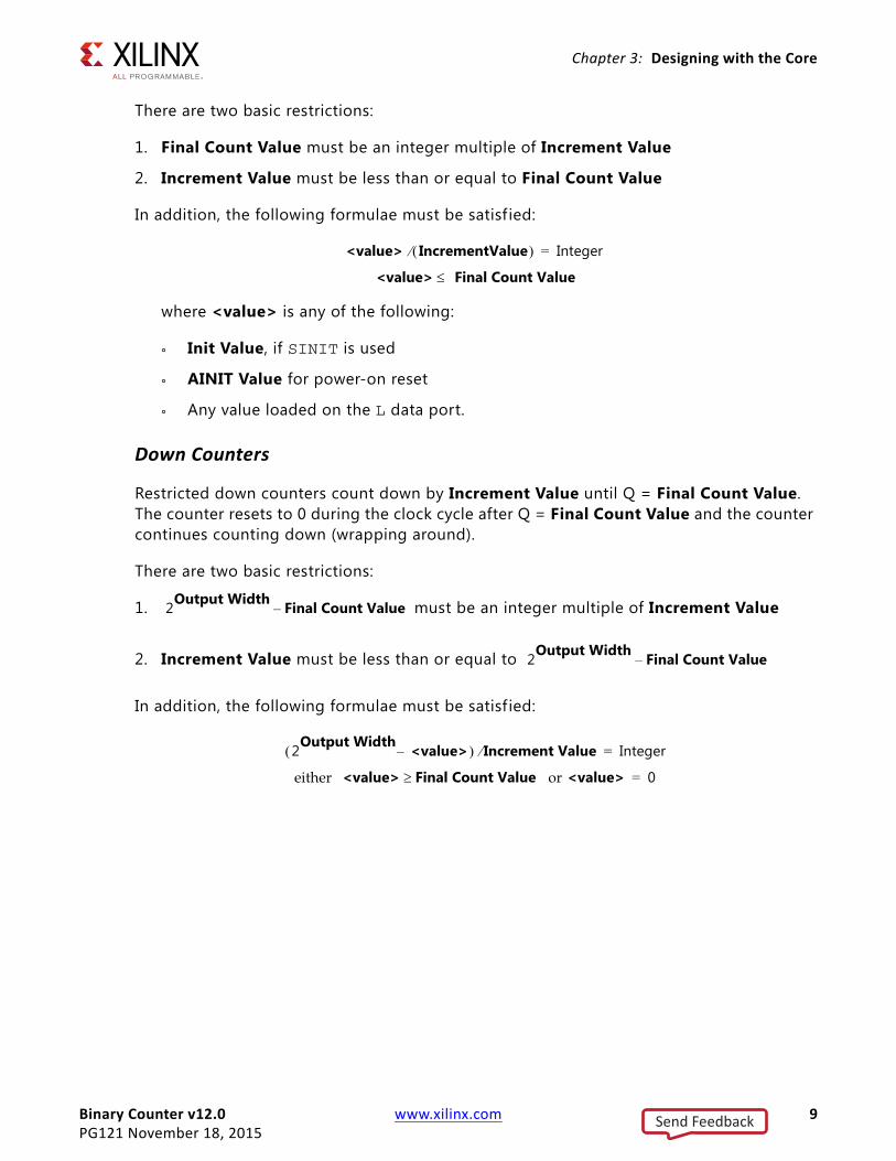
There are two basic restrictions:
1. Final Count Value must be an integer multiple of Increment Value
2. Increment Value must be less than or equal to Final Count Value
In addition, the following formulae must be satisf ied:
where <value> is any of the following:
° Init Value, if SINIT is used
° AINIT Value for power-on reset
° Any value loaded on the L data port.
Down Counters
Restricted down counters count down by Increment Value until Q = Final Count Value. The counter resets to 0 during the clock cycle after Q = Final Count Value and the counter continues counting down (wrapping around).
There are two basic restrictions:
1. must be an integer multiple of Increment Value
2. Increment Value must be less than or equal to
In addition, the following formulae must be satisf ied:
either or
<value> IncrementValue Integer=
<value> Final Count Value
2Output Width Final Count Value–
2Output Width Final Count Value–
2Output Width <value>– Increment Value Integer=
<value> Final Count Value <value> 0=
Send Feedback

Binary Counter v12.0 www.xilinx.com 10PG121 November 18, 2015
Chapter 3: Designing with the Core
where <value> is any of the following:
° Init Value, if SINIT is used
° AINIT Value for power-on reset
° Any value loaded on the L data port.
Use of LOAD
The Counter core can check on instantiation for sensible Init Value and power-on reset value, but it cannot check the data loaded on the L data port. Because of this, erroneous values loaded can cause unexpected behavior in the counter. For example, if a counter is given Final Count Value = 8 and Increment Value = 2, loading in 3 causes it to count the odd numbers and completely miss the limit value.
Load Support
The load operation in a DSP48 slice requires opmode control. The opmode control affects some of the same bits that are controlled to allow the terminal count reset feature. For the bits affected, external gating is required. This either impacts performance or requires an additional layer of latency in the feedback path. Despite being a constant, the Increment Value is registered so that the recover from SCLR latency matches the LOAD latency. The latency of the counter for the DSP48 slice implementation is therefore width dependant and varies as a function of Restrict Count, Loadable, Load Sense, Output Width.
The Load Enable in v9.0 and earlier has been deprecated. LOAD is always subject to CE (if present).
Moreover, the detection of the terminal count has been further improved in version 11.0, but to maintain backward-compatible behavior, the improved detection cannot be used when the counter is loadable.
Therefore it is strongly recommended that LOAD is not used with restricted counters; if such functionality is required, use external logic to create a greater-than-or-equal-to test rather than an equal-to test, or make sure the counter is simple (count by 1) and that a value is never loaded beyond Final Count Value.
Pipelined Operation
Pipelining the terminal count detection requires that the actual value detected is the terminal count value minus some multiple of the Increment Value value where the multiple is determined by the full cycle latency. This adds further restrictions to the valid combinations of Increment Value and Final Count Value. A run time assertion (warning) flags if a value is loaded which would cause the actual terminal count value to be missed.
Send Feedback

Binary Counter v12.0 www.xilinx.com 11PG121 November 18, 2015
Chapter 3: Designing with the Core
The following four new parameters allow for high performance:
• Latency Configuration
• Latency
• Feedback Latency Configuration
• Feedback Latency
The f irst two describe the number of cycles the core takes to recover from SCLR or from a LOAD value because it is the number of registers in the forward datapath. When Latency Configuration is set to Manual, Latency can be set to a specific number for specific latency. By setting Latency Configuration to Automatic, the latency for maximal performance is calculated internally and used in place of Latency. Maximal performance is defined as an operating frequency greater than or equal to the nominal operating speed of a fully pipelined DSP48 slice. This is achieved by splitting the carry-chain of the main count operation into splices and pipelining. The number of splices required is a function of the counter bit width and the family in question. Feedback Latency Configuration and Feedback Latency refer to the latency in the terminal count feedback circuit and hence apply only to restricted counters. The total amount of latency gives the number of cycles by which the terminal count detection must predict the terminal count value. When Feedback Latency Configuration is set to Manual, Feedback Latency can be set to a specific number for specif ic feedback latency. By setting Feedback Latency Configuration to Automatic, the feedback latency for maximal performance is calculated internally and used in place of Feedback Latency.
ClockingThe core requires a single clock, CLK, and is active-High triggered.
If selected, the active-High clock enable, CE, stalls all core processes when deasserted.
ResetsThe core has a single, active-High synchronous reset, SCLR. Asserting SCLR for a single cycle resets all registers in the core.
The priority of SCLR and CE pins can be selected when customizing the core.
Send Feedback
Binary Counter v12.0 www.xilinx.com 12PG121 November 18, 2015
Chapter 4
Design Flow StepsThis chapter describes customizing and generating the core, constraining the core, and the simulation, synthesis and implementation steps that are specific to this IP core. More detailed information about the standard Vivado® design flows and the IP integrator can be found in the following Vivado Design Suite user guides:
• Vivado Design Suite User Guide: Designing IP Subsystems using IP integrator (UG994) [Ref 1]
• Vivado Design Suite User Guide: Designing with IP (UG896) [Ref 2]
• Vivado Design Suite User Guide: Getting Started (UG910) [Ref 3]
• Vivado Design Suite User Guide: Logic Simulation (UG900) [Ref 6]
Customizing and Generating the CoreThis chapter includes information about using the Vivado® Design Suite and System Generator for DSP to customize and generate the core.
If you are customizing and generating the core in the Vivado IP integrator, see the Vivado Design Suite User Guide: Designing IP Subsystems using IP integrator (UG994) [Ref 1] for detailed information. IP integrator might auto-compute certain configuration values when validating or generating the design. To check whether the values do change, see the description of the parameter in this chapter. To view the parameter value you can run the validate_bd_design command in the Tcl Console.
Vivado Integrated Design Environment
You can customize the IP for use in your design by specifying values for the various parameters associated with the IP core using the following steps:
1. Select the IP from the IP catalog.
2. Double-click the selected IP or select the Customize IP command from the toolbar or right-click menu .
Send Feedback
Binary Counter v12.0 www.xilinx.com 13PG121 November 18, 2015
Chapter 4: Design Flow Steps
For details, see the Vivado Design Suite User Guide: Designing with IP (UG896) [Ref 2] and the “Working with the Vivado IDE” section in the Vivado Design Suite User Guide: Getting Started (UG910) [Ref 3].
Core Parameters
The Binary Counter core Vivado Integrated Design Environment (IDE) provides fields to set the parameter values for the required instantiation. This section provides a description of each Vivado IDE field.
• Implement using: Sets the implementation type to Fabric or DSP48.
• Output Width: Specif ies the width of the counter.
• Restrict Count: When this parameter is true the counter only counts up (or down) to the value specif ied in the Final Count Value parameter. When it is false the counter counts up to the maximum value that can be represented using the specif ied output width. This option is mutually exclusive with the up/down counter option and with synchronous set controls.
• Final Count Value: When Restrict Count = true, this parameter specif ies the hex representation of the upper limit of the counter.
• Increment Value: Specif ies in hex the increment value of the counter. When Restrict Count is false, the valid range is 1 to 2Output Width - 1. When Restrict Count is true, the valid settings for Increment Value are governed by the equation:
Final Count Value / Increment Value = Integer
for up counters, and:
2Output Width - Final Count Value / Increment Value = Integer
for down counters.
• Count Mode: This parameter specifies whether the counter counts up, down, or has its direction specif ied on the UP pin (up/down).
• Sync Threshold Output: When this parameter equals true, the THRESH0 combinatorial output is generated.
• Threshold Value: Specif ies the value at which the THRESH0 value is activated as a hex value.
• Loadable: Activating the LOAD pin (Loadable = true) allows the value on the L[N:0] input port to pass through the logic and be loaded into the output register on the next active clock edge. See the section, Use of LOAD for more information.
• Load Sense: Specif ies Active_High or Active_Low LOAD pin.
• CE: When set to true, the module is generated with a clock enable input.
Send Feedback

Binary Counter v12.0 www.xilinx.com 14PG121 November 18, 2015
Chapter 4: Design Flow Steps
• Power on Reset Init Value: Specif ies, in hex, the value that the output initializes to during power-up reset.
• Synchronous Clear (SCLR): Specif ies if an SCLR pin is to be included.
• SSET: Specifies if an SSET pin is to be included. SSET pin is not valid in DSP48 implementations. See Sync Set and Clear (Reset) Priority for SCLR/SSET priorities.
• SINIT: Specifies if an SINIT pin is to be included which, when asserted, synchronously sets the output value to the value defined by Init Value.
Note: If SINIT is present, then neither SSET nor SCLR can be present. SINIT pin is not valid in DSP48 implementations.
• Init Value: Specifies, in hex, the value that the output initializes to when SINIT is asserted. The Init Value is ignored if SINIT is false.
• Synchronous Controls and Clock Enable (CE) Priority: This parameter controls whether or not the SCLR, (and if fabric: SSET and SINIT) input is qualif ied by CE. When set to Sync_Overrides_CE, the synchronous control overrides the CE signal. When set to CE_Overrides_Sync, SCLR has an effect only when CE is high.
Note: On the fabric primitives, the SCLR and SSET controls override CE, so choosing CE_Overrides_Sync generally results in extra logic.
• Sync Set and Clear (Reset) Priority: Controls the relative priority of SCLR and SSET. When set to Reset_Overrides_Set, SCLR overrides SSET. The default is Reset_Overrides_Set, as this is the way the primitives are arranged. Making SSET take priority requires extra logic.
• Latency Configuration: Automatic or Manual; Automatic sets optimal latency for maximum speed; Manual allows user to set Latency to one of the allowed values.
• Latency: Value used for latency when Latency Configuration is set to Manual. See the section, Pipelined Operation for more information.
• Feedback Latency Configuration: Automatic or Manual; Automatic sets optimal feedback latency for maximum speed; Manual allows user to set Feedback Latency to one of the allowed values.
• Feedback Latency: Value used for latency when Feedback Latency Configuration is set to Manual. See the section, Pipelined Operation for more information.
Send Feedback

Binary Counter v12.0 www.xilinx.com 15PG121 November 18, 2015
Chapter 4: Design Flow Steps
User Parameters
Table 4-1 shows the relationship between the GUI f ields in the Vivado IDE (described in Vivado Integrated Design Environment) and the User Parameters (which can be viewed in the Tcl console).
Core Use through Vivado Design Suite
The Vivado IP catalog performs error-checking on all input parameters. Resource estimation and latency information is also available.
Several f iles are produced when a core is generated, and customized instantiation templates for Verilog and VHDL design flows are provided in the .veo and .vho f iles,
Table 4‐1: GUI Parameter to User Parameter Relationship
GUI Field Label User Parameter Default Value
Implement using implementation Fabric
Output Width output_width 16
Increment Value (HEX) increment_value 1
Restrict Count restrict_count False
Final Count Value (HEX) final_count_value 1
Count Mode count_mode Up
Sync Threshold Output sync_threshold_output False
Threshold Value (Hex) threshold_value 1
Clock Enable(CE) ce False
Synchronous Clear(SCLR) sclr False
Synchronous Set (SSET) sset False
Synchronous Init(SINIT) sinit False
Init Value(Hex) sinit_value 0
Synchronous Set and Clear(Reset) Priority
syncctrlpriority Reset_Overrides_Set
Synchronous Controls and Clock Enable(CE) Priority
sync_ce_priority Reset_Overrides_CE
Power-on Reset Init Value (Hex) ainit_value 0
Loadable load False
Latency Configuration latency_configuration Manual
Latency latency 1
Feedback Latency Configuration fb_latency_configuration Manual
Feedback Latency fb_latency 0
Load Sense load_sense Active_High
Send Feedback

Binary Counter v12.0 www.xilinx.com 16PG121 November 18, 2015
Chapter 4: Design Flow Steps
respectively. For detailed instructions, see the Vivado Design Suite: Designing with IP (UG896) [Ref 2].
Core Use through System Generator
The Binary Counter core is available through Xilinx® System Generator for DSP, a design tool that enables the use of the model-based design environment Simulink® software for FPGA design. The Binary Counter core is one of the DSP building blocks provided in the Xilinx DSP blockset for Simulink. The Binary Counter core can be found in the Xilinx Blockset in the Math section. The block is called Counter. See the System Generator for DSP User Guide (UG640) [Ref 4] for more information.
Output Generation
For details, see “Generating IP Output Products” in the Vivado Design Suite User Guide: Designing with IP (UG896) [Ref 6].
Constraining the CoreThere are no constraints associated with this core.
SimulationFor comprehensive information about Vivado® simulation components, as well as information about using supported third-party tools, see the Vivado Design Suite User Guide: Logic Simulation (UG900) [Ref 6].
Synthesis and ImplementationFor details about synthesis and implementation, see “Synthesizing IP” and “Implementing IP” in the Vivado Design Suite User Guide: Designing with IP (UG896) [Ref 2].
Send Feedback
Binary Counter v12.0 www.xilinx.com 17PG121 November 18, 2015
Chapter 5
Example DesignNo example design is provided for this core.
Send Feedback

Binary Counter v12.0 www.xilinx.com 18PG121 November 18, 2015
Chapter 6
Test BenchNo demonstration test bench is provided for this core.
Send Feedback
Binary Counter v12.0 www.xilinx.com 19PG121 November 18, 2015
Appendix A
Migrating and UpgradingThis appendix contains information about migrating a design from ISE® to the Vivado® Design Suite, and for upgrading to a more recent version of the IP core. For customers upgrading in the Vivado Design Suite, important details (where applicable) about any port changes and other impact to user logic are included.
Migrating to the Vivado Design Suite
Updating from Binary Counter v9.0 and later
The Vivado Design Suite IP update feature can be used to update an existing Binary Counter to version 12.0 of the core. The core can then be regenerated to create a new netlist. For information about migrating to the Vivado Design Suite, see the ISE to Vivado Design Suite Migration Guide (UG911) [Ref 6].
Updating from Versions Prior to Binary Counter v9.0
It is not currently possible to automatically update versions of the Binary Counter core prior to v9.0. Some features and configurations are unavailable in Binary Counter v12.0. Also, some port names differ between versions.
RECOMMENDED: Use the Binary Counter v12.0 GUI in the Vivado Design Suite to customize a new core.
Upgrading in the Vivado Design SuiteThis section provides information about any changes to the user logic or port designations that take place when you upgrade to a more current version of this IP core in the Vivado Design Suite.
Parameter Changes
There are no parameter changes in Binary Counter v12.0 compared to v9.0 and later.
Send Feedback

Binary Counter v12.0 www.xilinx.com 20PG121 November 18, 2015
Appendix A: Migrating and Upgrading
Port Changes
There are no port changes in Binary Counter v12.0 compared to v9.0 and later.
Functionality Changes
There are no changes in functionality in Binary Counter v12.0 compared to v9.0 and later.
Simulation
Starting with Binary Counter v12.0 (2013.3 version), behavioral simulation models have been replaced with IEEE P1735 Encrypted VHDL. The resulting model is bit and cycle accurate with the f inal netlist. For more information on simulation, see the Vivado Design Suite User Guide: Logic Simulation (UG900) [Ref 6].
Send Feedback

Binary Counter v12.0 www.xilinx.com 21PG121 November 18, 2015
Appendix B
DebuggingThis appendix includes details about resources available on the Xilinx Support website and debugging tools.
Finding Help on Xilinx.comTo help in the design and debug process when using the Binary Counter, the Xilinx Support web page contains key resources such as product documentation, release notes, answer records, information about known issues, and links for obtaining further product support.
Documentation
This product guide is the main document associated with the Binary Counter. This guide, along with documentation related to all products that aid in the design process, can be found on the Xilinx Support web page or by using the Xilinx Documentation Navigator.
Download the Xilinx Documentation Navigator from the Downloads page. For more information about this tool and the features available, open the online help after installation.
Answer Records
Answer Records include information about commonly encountered problems, helpful information on how to resolve these problems, and any known issues with a Xilinx product. Answer Records are created and maintained daily ensuring that users have access to the most accurate information available.
Answer Records for this core are listed below, and can be located by using the Search Support box on the main Xilinx support web page. To maximize your search results, use proper keywords such as
• Product name
• Tool messages
• Summary of the issue encountered
A filter search is available after results are returned to further target the results.
Send Feedback
Binary Counter v12.0 www.xilinx.com 22PG121 November 18, 2015
Appendix B: Debugging
Master Answer Record for the Binary Counter
AR 54493
Technical Support
Xilinx provides technical support in the Xilinx support web page for this LogiCORE™ IP product when used as described in the product documentation. Xilinx cannot guarantee timing, functionality, or support if you do any of the following:
• Implement the solution in devices that are not defined in the documentation.
• Customize the solution beyond that allowed in the product documentation.
• Change any section of the design labeled DO NOT MODIFY.
To contact Xilinx Technical Support, navigate to the Xilinx Support web page.
Debug ToolsThere are many tools available to address IP core design issues. It is important to know which tools are useful for debugging various situations.
Vivado Design Suite Debug Feature
The debug feature inserts logic analyzer and virtual I/O cores directly into your design. The debug feature also allow you to set trigger conditions to capture application and integrated block port signals in hardware. Captured signals can then be analyzed. This feature in the Vivado IDE is used for logic debugging and validation of a design running in Xilinx devices.
The Vivado logic analyzer is used to interact with the logic debug LogiCORE™ IP cores, including:
• ILA 2.0 (and later versions)
• VIO 2.0 (and later versions)
See Vivado Design Suite User Guide: Programming and Debugging (UG908) [Ref 7].
Send Feedback
Binary Counter v12.0 www.xilinx.com 23PG121 November 18, 2015
Appendix C
Additional Resources and Legal Notices
Xilinx ResourcesFor support resources such as Answers, Documentation, Downloads, and Forums, see Xilinx Support.
ReferencesThese documents provide supplemental material useful with this product guide:
1. Vivado Design Suite User Guide: Designing IP Subsystems using IP integrator (UG994)
2. Vivado Design Suite User Guide: Designing with IP (UG896)
3. Vivado Design Suite User Guide: Getting Started (UG910)
4. System Generator for DSP User Guide (UG640)
5. ISE to Vivado Design Suite Migration Methodology Guide (UG911)
6. Vivado Design Suite User Guide: Logic Simulation (UG900)
7. Vivado Design Suite User Guide: Programming and Debugging (UG908)
Revision HistoryThe following table shows the revision history for this document.
Date Version Revision
11/18/2015 12.0 Added support for UltraScale+ families.
04/02/2014 12.0 Updated resource utilization information.
12/18/2013 12.0 • Added UltraScale™ architecture support information.• Added Simulation, Synthesis, Example Design and Test Bench chapters.• Updated Migrating appendix.
Send Feedback

Binary Counter v12.0 www.xilinx.com 24PG121 November 18, 2015
Appendix C: Additional Resources and Legal Notices
Please Read: Important Legal NoticesThe information disclosed to you hereunder (the "Materials") is provided solely for the selection and use of Xilinx products. To the maximum extent permitted by applicable law: (1) Materials are made available "AS IS" and with all faults, Xilinx hereby DISCLAIMS ALL WARRANTIES AND CONDITIONS, EXPRESS, IMPLIED, OR STATUTORY, INCLUDING BUT NOT LIMITED TO WARRANTIES OF MERCHANTABILITY, NON-INFRINGEMENT, OR FITNESS FOR ANY PARTICULAR PURPOSE; and (2) Xilinx shall not be liable (whether in contract or tort, including negligence, or under any other theory of liability) for any loss or damage of any kind or nature related to, arising under, or in connection with, the Materials (including your use of the Materials), including for any direct, indirect, special, incidental, or consequential loss or damage (including loss of data, profits, goodwill, or any type of loss or damage suffered as a result of any action brought by a third party) even if such damage or loss was reasonably foreseeable or Xilinx had been advised of the possibility of the same. Xilinx assumes no obligation to correct any errors contained in the Materials or to notify you of updates to the Materials or to product specifications. You may not reproduce, modify, distribute, or publicly display the Materials without prior written consent. Certain products are subject to the terms and conditions of Xilinx's limited warranty, please refer to Xilinx's Terms of Sale which can be viewed at http://www.xilinx.com/legal.htm#tos; IP cores may be subject to warranty and support terms contained in a license issued to you by Xilinx. Xilinx products are not designed or intended to be fail-safe or for use in any application requiring fail-safe performance; you assume sole risk and liability for use of Xilinx products in such critical applications, please refer to Xilinx's Terms of Sale which can be viewed at http://www.xilinx.com/legal.htm#tos.© Copyright 2013-2015 Xilinx, Inc. Xilinx, the Xilinx logo, Artix, ISE, Kintex, Spartan, Virtex, Vivado, Zynq, and other designated brands included herein are trademarks of Xilinx in the United States and other countries. All other trademarks are the property of their respective owners.
10/02/2013 12.0 Minor updates to IP Facts table and Migrating appendix. Document version number advanced to match the core version number.
03/20/2013 1.0 First release as a product guide; replaces the LogiCORE IP Binary Counter Data Sheet (DS215).
Date Version Revision
Send Feedback