brushless motor parameter optimization report - andy...
TRANSCRIPT

~ 1 ~
Brushless Motor Parameter Optimization
Report Spring 2011
May 6, 2011
Alicia Violeta Juarez Crow
ECE 2012 1439 Kentfield Ave. Apt. 2 Redwood City, CA 94061
(650)395‐7846 [email protected]
ECE 4999 Final Report 3 credits
Biorobotics and Locomotion Lab Cornell University

~ 2 ~
Table of Contents
I. Introduction....................................................................................................................... 3 II. Methods and Results ..........................................................Error! Bookmark not defined.
A. Test 1............................................................................Error! Bookmark not defined. B. Test 4............................................................................Error! Bookmark not defined. C. Test 5........................................................................................................................... 5 D. Test 6............................................................................Error! Bookmark not defined. E. Test 7............................................................................Error! Bookmark not defined. F. Test 8............................................................................Error! Bookmark not defined. G. Test 9............................................................................Error! Bookmark not defined. H. Test 10..........................................................................Error! Bookmark not defined. I. Test 11..........................................................................Error! Bookmark not defined.
III. Conclusion ..........................................................................Error! Bookmark not defined. IV. Citations............................................................................................................................. 6 V. Appendices ........................................................................................................................ 7
A. Motor .......................................................................................................................... 7 B. Motor controller board................................................................................................. 8 C. Test 1........................................................................................................................... 8 D. Test 4..........................................................................................................................10 E. Test 5..........................................................................................................................11 F. Test 6..........................................................................................................................13 G. Test 7..........................................................................................................................14 H. Test 8..........................................................................................................................14 I. Test 9..........................................................................................................................15 J. Test 10........................................................................................................................18 K. Test 11........................................................................................................................19 L. Test 11b......................................................................................................................24

~ 3 ~
I. Introduction
Given the currently available means to actuate robots, it is a challenge to design
efficient robots without sacrificing functionality. A walking robot, for example, should
draw the least amount of power possible while walking normally, but it should be able to
draw the necessary amount of power to catch itself if it needs to.
Evidence suggests that brushless motors, despite being difficult to control, have a
number of advantages over brushed motors. One of the reasons is that brushless motors
can run longer at higher power because the electromagnets in the stator are easier to cool
than those in the rotor of a brushed motor (Clementi 3). Another disadvantage of brushed
motors, explained by Jason Cortell, is that “the noise and voltage drop across the brushes
of a brushed motor wastes power and makes current control in the rotor more
challenging”. The motor used for this project was the Maxon EC-powermax, 22mm,
blushless, 90 Watt, order number 311536, which had been previously selected. Technical
information can be found in the Appendix A.
The purpose of this series of tests was to help design a controller for the selected
motor by finding optimum parameters for the motor in different regions of operation
while having a design that is efficient, light, and provides the necessary amount of power.
PWM frequency and series inductance are the main parameters to consider. Adding
inductance can reduce power loss if a certain amount of current is being drawn. However,
this adds weight and volume to the robot.
The motor controller board used to conduct most of the tests was built by Brian
Clementi. Appendix B contains figures and diagrams that depict the setup of the board.

~ 4 ~
For more detailed information on the controller refer to "Brushless Motor Controller
Report", Spring 2010.
Controlling the speed of the motor with constant voltage would make the system
heat up and this would result in power loss. Several options for driving a brushless motor
are described in the Shane Colton’s Thesis. The two main methods described are
sinusoidal wave drive and square wave drive, also known as six-step drive. Which one to
use usually depends on the shape of the back EMF wave of the motor.
Figure 1 Sinusoidal and Square Wave drive waveforms (Colton 17)
Colton analyzes two ideal cases: sinusoidal back EMF with sinusoidal drive, which is
considered AC, and trapezoidal back EMF with six-step drive, which is considered DC.
The latter has the advantage of producing more torque per unit heat dissipation,
theoretically ripple-free. However, when motor inductance is considered, sharp
transitions in current are no longer possible and a rise and fall time appears. This leads to
torqure ripple and additional heat dissipation in the controller diodes.
The method used in this controller is Pulse Width Modulation (PWM). Ideally,
the wave should be a square wave, as shorter transition time results in more efficiency. In
Violeta Crow � 6/5/11 1:57 PMComment: Clementi’s report is not very clear about why this was chosen

~ 5 ~
practice, as described in the previous paragraph, the transitions are gradual.
The motor can be modeled by an inductor-resistor circuit.
The power loss in the resistor is given by �=�e lowest at a frequency of about 100kHz.
A. Test 5
The objective of this test was to find the power consumed by the motor itself. This
was done by measuring the current in the system, measuring the current in the motor
controller board without a motor, and then subtracting them. The voltage was held at
29.6V. The PWM was varied from 5 to 590. A tachometer was used to measure the speed
of the motor in revolutions per minute (RPM).
Figure 2 Comparison of power consumed by system, board, and motor
The blue line in the graph shows that the power consumed by the board was
constant, except at high speeds, at which it suddenly decreased.
The equation obtained from the trend line of the power consumption of the motor
was �=7·o need modifications to be able to perform the necessary adjustments. Further
experimentation should be done as the design of the final motor controller progresses.
Violeta Crow � 6/3/11 3:58 PM
Violeta Crow � 6/3/11 4:01 PM
Comment: Voltage of what?
Comment: Why?

~ 6 ~
II. Citations
Clementi, Brian. "Brushless Motor Controller Report." MAE 4900 Final Report. Cornell
University, 2010.
Colton, Shane W. "Design and Prototyping Methods for Brushless Motors." Master of
Science Thesis. Massachusetts Institute of Technology, 2010.
Cortell, Jason. "Lab Report Edits and Additions." Message to the author. 28 May 2011. E-mail.

~ 7 ~
III. Appendices
A. Motor
Maxon EC-powermax, 22mm, blushless, 90 Watt, order number 311536
Motor data Assigned power rating W 120 Nominal voltage V 24 No load speed min-¹ 16800 Stall torque mNm 990 Max. continuous torque mNm 54.3 Speed / torque gradient min-¹ / mNm-¹ 17.1 No load current mA 406 Starting current A 73.1 Max. permissible speed min-¹ 25000 Nominal current (max. continuous current) A 4.36
Max. efficiency % 86 Torque constant mNm / A-¹ 13.5 Speed constant min-¹ / V-¹ 705 Mechanical time constant ms 1.59 Rotor inertia gcm² 8.91 Terminal inductance mH 30.8 Thermal resistance housing-ambient KW-¹ 8.01 Thermal resistance winding-housing KW-¹ 1 Thermal time constant winding s 6.4 Motor length mm 66 Weight g 175

~ 8 ~
B. Motor controller board
Figure 3 Brushless Motor Controller Composed of pseudo-controller (bottom) and original controller (top)
Figure 4 Motor controller board setup
C. Test 1
• Date: February 2, 2011

~ 9 ~
• Materials used: - Tektronix CFC250, 100MHz Frequency Counter - Regulator Power supply. Model LCS-A-01 - CIC Ps-1930, DC Power Supply - FLUKE True RMS Multimeter - Motor: Maxon EC-powermax, 22mm, blushless, 90 Watt, order number 311536 - Brushless motor controller
• Controlled variables: PWM and voltage
• Dependent variables: Current and Frequency
PWM = 50 Voltage (V) Current(A) Frequency(Hz) RPM
10 0.02 10 600 12 0.02 12 720 12.5 0.02 12 720 14 0.02 14 840 15 0.02 14 840 16 0.02 16 960 17.5 0.02 17 1020 19 0.02 21 1260 20 0.03 20 1200 22.5 0.03 23 1380 25 0.03 25 1500
PWM = 200
Voltage (V) Current(A) Frequency(Hz) RPM 10 0.07 43 2580 12 0.08 51 3060 14 0.09 59 3540 16 0.1 67 4020 18 0.11 79 4740 20 0.115 86 5160 22 0.12 97.5 5850 24 0.13 104 6240 26 0.14 107 6420 28 0.145 126 7560 29.7 0.15 135.5 8130
PWM = 500
Voltage (V) Current(A) Frequency(Hz) RPM 10 0.11 70 4200

~ 10 ~
D. Test 4
• Date: February 23, 2011
• Materials used: - Regulator Power supply. Model LCS-A-01 - CIC Ps-1930, DC Power Supply - FLUKE True RMS Multimeter - Motor: Maxon EC-powermax, 22mm, blushless, 90 Watt, order number 311536 - Brushless motor controller
• Controlled variables: PWM
• Dependent variables: Current
Current (A)
Frequency (kHz) All inductors connected One inductor shorted Two inductors shorted 20 0.048 ‐ ‐ 50 0.024 0.046 ‐ 60 0.023 0.041 ‐ 80 0.022 0.037 ‐ 100 0.022 0.035 ‐ 120 0.023 0.034 0.117 150 0.024 0.033 ‐ 200 0.027 0.035 0.107 300 0.036 0.041 0.098 400 0.045 0.049 0.096 500 ‐ 0.057 0.098 600 ‐ 0.067 0.101
12 0.12 74 4440 14 0.13 87.5 5250 16 0.14 107.5 6450 18 0.15 112 6720 20 0.16 129 7740 22 0.17 139.5 8370 24 0.18 150 9000 26 0.19 178 10680 28 0.2 200.5 12030 29.7 0.21 184 11040

~ 11 ~
E. Test 5
• Date: February 23, 2011
• Materials used: - Regulator Power supply. Model LCS-A-01 - CIC Ps-1930, DC Power Supply - FLUKE True RMS Multimeter - Motor: Maxon EC-powermax, 22mm, blushless, 90 Watt, order number 311536 - Brushless motor controller
• Controlled variables: PWM
• Dependent variables: Current and speed
PWM RPM System Current (A) Board current (A) Motor current (A) Motor Power (W)
5 183 0.01 0.01 0 0 10 352 0.012 0.011 0.001 0.0296 20 934 0.012 0.012 0 0 40 1520 0.014 0.012 0.002 0.0592 60 2173 0.017 0.012 0.005 0.148 80 2834 0.02 0.012 0.008 0.2368 100 3490 0.024 0.012 0.012 0.3552 120 4150 0.028 0.012 0.016 0.4736 140 4820 0.032 0.012 0.02 0.592 160 5497 0.036 0.012 0.024 0.7104 180 6277 0.037 0.012 0.025 0.74 200 6854 0.046 0.012 0.034 1.0064

~ 12 ~
225 7700 0.052 0.012 0.04 1.184 250 8536 0.059 0.012 0.047 1.3912 275 9385 0.066 0.012 0.054 1.5984 300 10226 0.074 0.012 0.062 1.8352 325 11280 0.081 0.012 0.069 2.0424 350 11945 0.09 0.012 0.078 2.3088 375 12798 0.097 0.012 0.085 2.516 400 13648 0.105 0.012 0.093 2.7528 425 14493 0.114 0.012 0.102 3.0192 450 15379 0.123 0.012 0.111 3.2856 475 16245 0.132 0.012 0.12 3.552 500 17111 0.14 0.012 0.128 3.7888 530 18098 0.152 0.012 0.14 4.144 560 18945 0.162 0.012 0.15 4.44 590 19943 0.169 0.004 0.165 4.884

~ 13 ~
F. Test 6
• Date: March 9, 2011
• Materials used: - Regulator Power supply. Model LCS-A-01 - CIC Ps-1930, DC Power Supply - FLUKE True RMS Multimeter - Brushless motor controller
• Controlled variables: PWM
• Dependent variables: Current
Current (A)
Frequency (kHz) No
motor All inductors connected
One inductor shorted
Two inductors shorted
50 0.01 0.014 0.036 ‐ 60 0.011 0.012 0.03 ‐ 80 0.013 0.009 0.024 ‐ 100 0.016 0.006 0.019 ‐ 120 0.018 0.005 0.016 0.099

~ 14 ~
150 0.022 0.002 0.011 ‐ 200 0.028 ‐0.001 0.007 0.079 300 0.04 ‐0.004 0.001 0.058 400 0.051 ‐0.006 ‐0.002 0.045 500 0.063 ‐ ‐0.006 0.035 600 0.076 ‐ ‐0.009 0.025
G. Test 7
• Date: March 11, 2011
• Materials used: - Regulator Power supply. Model LCS-A-01 - CIC Ps-1930, DC Power Supply - FLUKE True RMS Multimeter - Brushless motor controller
• Controlled variables: PWM
• Dependent variables: Current
Voltage (V) PWM Current (A)
Normal test 24 586 0.154 Pipe over it 24 586 0.157
H. Test 8
• Date: March 9, 2011

~ 15 ~
• Materials used: - Regulator Power supply. Model LCS-A-01 - CIC Ps-1930, DC Power Supply - FLUKE True RMS Multimeter - Brushless motor controller
• Controlled variables: PWM
• Dependent variables: Current
Current (A)
Frequency (kHz) All inductors connected All inductors (Test 6) 50 0.016 0.014 60 0.012 0.012 80 0.009 0.009 100 0.006 0.006 120 0.004 0.005 150 0.002 0.002 200 ‐0.001 ‐0.001 300 ‐0.005 ‐0.004 400 ‐0.006 ‐0.006
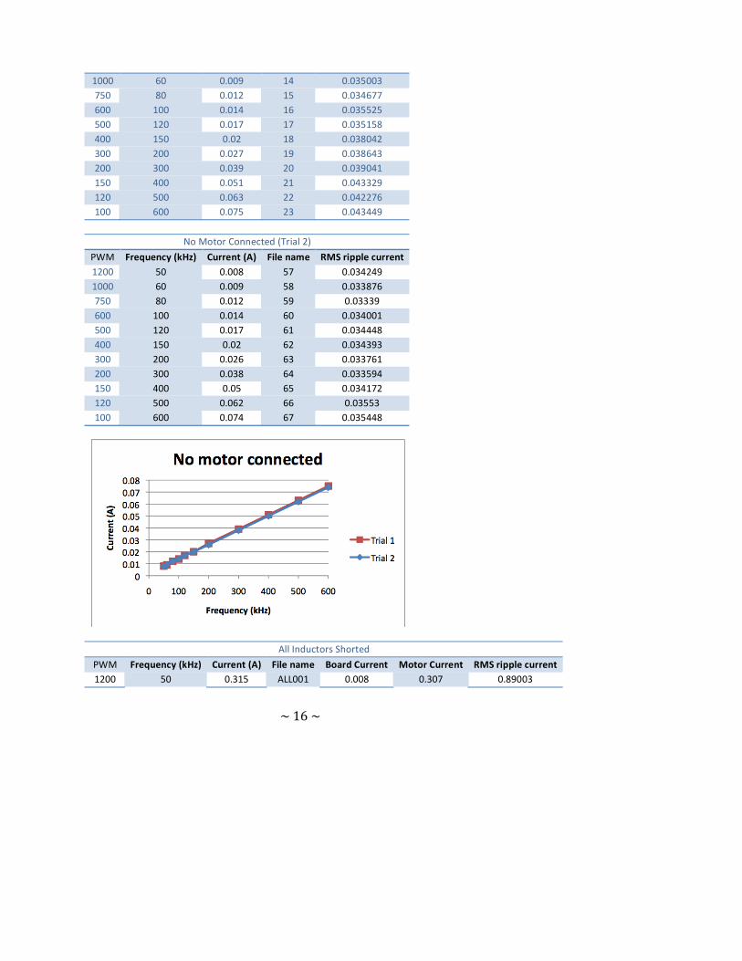
I. Test 9
• Date: March 18, 2011
• Materials used: - Regulator Power supply. Model LCS-A-01 - CIC Ps-1930, DC Power Supply - FLUKE True RMS Multimeter - BK Toolkit 2704B Multimeter - AM 503 Current Probe Amplifier - Motor: Maxon EC-powermax, 22mm, blushless, 90 Watt, order number 311536 - 47µH inductors (3) - Brushless motor controller
• Controlled variables: PWM
• Dependent variables: Current
No Motor Connected (Trial 1)
PWM Frequency (kHz) Current (A) File name RMS ripple current 1200 50 0.008 13 0.034348
~ 16 ~
1000 60 0.009 14 0.035003 750 80 0.012 15 0.034677 600 100 0.014 16 0.035525 500 120 0.017 17 0.035158 400 150 0.02 18 0.038042 300 200 0.027 19 0.038643 200 300 0.039 20 0.039041 150 400 0.051 21 0.043329 120 500 0.063 22 0.042276 100 600 0.075 23 0.043449
No Motor Connected (Trial 2)
PWM Frequency (kHz) Current (A) File name RMS ripple current 1200 50 0.008 57 0.034249 1000 60 0.009 58 0.033876 750 80 0.012 59 0.03339 600 100 0.014 60 0.034001 500 120 0.017 61 0.034448 400 150 0.02 62 0.034393 300 200 0.026 63 0.033761 200 300 0.038 64 0.033594 150 400 0.05 65 0.034172 120 500 0.062 66 0.03553 100 600 0.074 67 0.035448
All Inductors Shorted
PWM Frequency (kHz) Current (A) File name Board Current Motor Current RMS ripple current 1200 50 0.315 ALL001 0.008 0.307 0.89003

~ 17 ~
1000 60 0.285 ALL002 0.009 0.276 0.847195 750 80 0.242 ALL003 0.012 0.23 0.685954 600 100 0.213 ALL004 0.014 0.199 0.580594 500 120 0.192 ALL005 0.017 0.175 0.505113 400 150 0.17 ALL006 0.02 0.15 0.4362 300 200 0.147 ALL007 0.027 0.12 0.343003 200 300 0.126 ALL008 0.039 0.087 0.255333 150 400 0.117 ALL010 0.051 0.066 0.2084 120 500 0.115 ALL011 0.063 0.052 0.177751 100 600 0.116 ALL012 0.075 0.041 0.155089
Two inductors in parallel
PWM Frequency
(kHz) Current (A)
File name
Board Current
Motor Current
RMS ripple current
1200 50 0.101 24 0.008 0.093 0.495382842 1000 60 0.09 25 0.009 0.081 0.457676917 750 80 0.075 26 0.012 0.063 0.358961168 600 100 0.065 27 0.014 0.051 0.296708342 500 120 0.059 28 0.017 0.042 0.252909154 400 150 0.053 29 0.02 0.033 0.212623611 300 200 0.049 30 0.027 0.022 0.164418004 200 300 0.05 31 0.039 0.011 0.118333089 150 400 0.054 32 0.051 0.003 0.097417042 120 500 0.062 33 0.063 ‐0.001 0.08418931 100 600 0.07 34 0.075 ‐0.005 0.07306326
One Inductor
PWM Frequency
(kHz) Current (A)
File name
Board Current
Motor Current
RMS ripple current
1200 50 0.056 35 0.008 0.048 0.336401902 1000 60 0.049 36 0.009 0.04 0.307357512 750 80 0.042 37 0.012 0.03 0.240401664 600 100 0.037 38 0.014 0.023 0.200179519 500 120 0.035 39 0.017 0.018 0.168229843 400 150 0.034 40 0.02 0.014 0.139100539 300 200 0.034 41 0.027 0.007 0.110307933 200 300 0.04 42 0.039 0.001 0.080302428 150 400 0.048 43 0.051 ‐0.003 0.07006968 120 500 0.057 44 0.063 ‐0.006 0.06145958 100 600 0.066 45 0.075 ‐0.009 0.057209789
All Inductors Connected
PWM Frequency (kHz) Current (A) File name Board Current Motor Current RMS ripple current
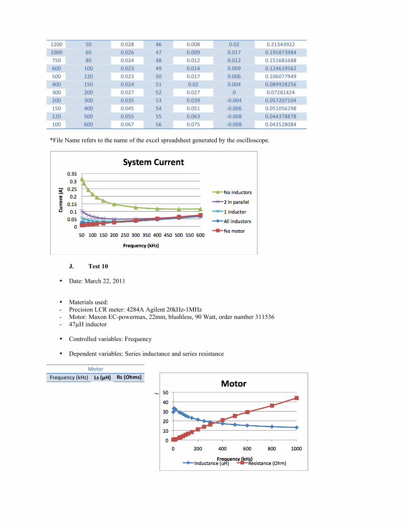
~ 18 ~
1200 50 0.028 46 0.008 0.02 0.21343922 1000 60 0.026 47 0.009 0.017 0.195873984 750 80 0.024 48 0.012 0.012 0.151681688 600 100 0.023 49 0.014 0.009 0.124619562 500 120 0.023 50 0.017 0.006 0.106077949 400 150 0.024 51 0.02 0.004 0.089928256 300 200 0.027 52 0.027 0 0.07281424 200 300 0.035 53 0.039 ‐0.004 0.057207104 150 400 0.045 54 0.051 ‐0.006 0.051056298 120 500 0.055 55 0.063 ‐0.008 0.044378878 100 600 0.067 56 0.075 ‐0.008 0.043528084
*File Name refers to the name of the excel spreadsheet generated by the oscilloscope.
J. Test 10
• Date: March 22, 2011
• Materials used: - Precision LCR meter: 4284A Agilent 20kHz-1MHz - Motor: Maxon EC-powermax, 22mm, blushless, 90 Watt, order number 311536 - 47µH inductor
• Controlled variables: Frequency
• Dependent variables: Series inductance and series resistance
Motor
Frequency (kHz) Ls (µH) Rs (Ohms)

~ 19 ~
1 29.22 0.332 5 32.85 0.361 10 32.93 0.456 20 31.94 0.801 50 28.95 2.36 60 28.4 2.88 80 26.98 4.01 100 25.4 5.28 120 24.22 6.59 150 23.07 8.19 200 21.27 11.03 250 19.74 13.77 300 18.76 16.18 400 17.11 20.75 500 15.97 25.1 600 15.09 29.11 800 13.88 35.95
1000 13.05 43.9
Inductor
Frequency (kHz) Ls (µH) Rs (Ohms)
1 52.92 0.078 5 52.65 0.107 10 52.7 0.162 20 52.32 0.296 50 51.84 0.76 60 52.27 0.693 80 51.99 0.9 100 51.37 1.33 120 51.35 1.56 150 51.22 1.85 200 51.08 2.48 250 50.82 3.22 300 50.8 3.87 400 50.68 5.3 500 50.75 6.93 600 50.94 8.63 800 51.71 11.5
1000 52.94 16.6
K. Test 11
• Date: March 29, 2011

~ 20 ~
• Materials used: - LabView simulation programmed by Jason Cortell
• Controlled variables: Frequency, Motor speed
• Dependent variables: Motor Electrical loss, RMS motor current
No Inductor Motor Speed
(rad/s) Frequency
(kHz) Inductance
(uH) Resistance (Ohm)
RMS motor current (A)
Motor electrical loss (W)
Average motor Current (A)
Duty cycle
0 100 25.4 5.28 0.00087 4.05E‐06 0.00075 1.00E‐05 0 200 21.27 11.03 0.00089 8.75E‐06 0.00072 1.00E‐05 0 300 18.76 16.18 0.00094 1.43E‐05 0.00074 1.00E‐05 0 400 17.11 20.75 0.000997 2.06E‐05 0.00077 1.00E‐05 500 100 25.4 5.28 0.611 1.97E+00 0.00037 1.69E‐01 500 200 21.27 11.03 0.357 1.40E+00 0.00018 1.69E‐01 500 300 18.76 16.18 0.266 1.15E+00 0.00041 1.69E‐01 500 400 17.11 20.75 0.217 9.77E‐01 9.64E‐05 1.69E‐01 1000 100 25.4 5.28 0.968 4.94 6.01E‐16 0.3375 1000 200 21.27 11.03 0.564 3.50E+00 0.00109 3.38E‐01 1000 300 18.76 16.18 0.419 2.84E+00 8.34E‐05 3.37E‐01 1000 400 17.11 20.75 0.342 2.42E+00 1.90E‐04 3.38E‐01 1500 100 25.4 5.28 1.08 6.16 0.00037 0.5063 1500 200 21.27 11.03 0.628 4.35 ‐0.00016 0.5062 1500 300 18.76 16.18 0.467 3.53 ‐0.00024 0.5061 1500 400 17.11 20.75 0.381 3.01 0.000289 0.5061 2000 100 25.4 5.28 0.95 4.76 5.13E‐16 0.675 2000 200 21.27 11.03 0.553 3.37 0.00145 0.6753 2000 300 18.76 16.18 0.412 2.74 0.00016 0.6749 2000 400 17.11 20.75 0.335 2.33 0.00038 0.6751
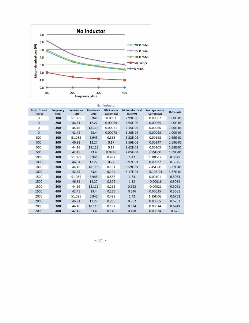
~ 21 ~
Half Inductor Motor Speed
(rad/s) Frequency
(kHz) Inductance
(uH) Resistance (Ohm)
RMS motor current (A)
Motor electrical loss (W)
Average motor Current (A)
Duty cycle
0 100 51.085 5.945 0.0007 2.99E‐06 0.00067 1.00E‐05 0 200 46.81 12.27 0.00069 5.94E‐06 0.00065 1.00E‐05 0 300 44.16 18.115 0.00071 9.15E‐06 0.00066 1.00E‐05 0 400 42.45 23.4 0.00073 1.26E‐05 0.00068 1.00E‐05 500 100 51.085 5.945 0.313 5.82E‐01 0.00168 1.69E‐01 500 200 46.81 12.27 0.17 3.56E‐01 0.00147 1.69E‐01 500 300 44.16 18.115 0.12 2.62E‐01 0.00103 1.69E‐01 500 400 42.45 23.4 0.0936 2.05E‐01 8.55E‐05 1.69E‐01 1000 100 51.085 5.945 0.497 1.47 6.30E‐17 0.3375 1000 200 46.81 12.27 0.27 8.97E‐01 0.00032 0.3375 1000 300 44.16 18.115 0.191 6.59E‐01 7.45E‐05 3.37E‐01 1000 400 42.45 23.4 0.149 5.17E‐01 ‐5.10E‐04 3.37E‐01 1500 100 51.085 5.945 0.556 1.84 0.00101 0.5064 1500 200 46.81 12.27 0.302 1.12 ‐0.00016 0.5062 1500 300 44.16 18.115 0.213 0.822 ‐0.00021 0.5061 1500 400 42.45 23.4 0.166 0.646 0.00025 0.5061 2000 100 51.085 5.945 0.488 1.42 1.35E‐03 0.6752 2000 200 46.81 12.27 0.265 0.862 0.00065 0.6752 2000 300 44.16 18.115 0.187 0.634 0.00014 0.6749 2000 400 42.45 23.4 0.146 0.498 0.00034 0.675

~ 22 ~
One Inductor Motor Speed
(rad/s) Frequency
(kHz) Inductance
(uH) Resistance (Ohm)
RMS motor current (A)
Motor electrical loss (W)
Average motor Current (A)
Duty cycle
0 100 76.77 6.61 0.00062 2.57E‐06 0.0006 5.00E‐05 0 200 72.35 13.51 0.00061 5.08E‐06 0.00059 2.00E‐04 0 300 69.56 20.05 0.00062 7.74E‐06 0.0006 3.00E‐04 0 400 67.79 26.05 0.000638 1.06E‐05 0.00061 4.00E‐04 500 100 76.77 6.61 0.209 2.90E‐01 0.0003 1.69E+00 500 200 72.35 13.51 0.111 1.67E‐01 0.00133 1.69E‐01 500 300 69.56 20.05 0.0768 1.18E‐01 ‐0.00026 1.69E‐01 500 400 67.79 26.05 0.0592 9.12E‐02 7.68E‐05 1.69E‐01 1000 100 76.77 6.61 0.333 0.735 0.000605 0.3376 1000 200 72.35 13.51 0.177 0.421 0.00029 0.33745 1000 300 69.56 20.05 0.122 0.3 6.70E‐05 0.33745 1000 400 67.79 26.05 0.0942 0.231 0.00015 0.3374 1500 100 76.77 6.61 0.373 0.917 0.00151 0.5065 1500 200 72.35 13.51 0.197 0.526 ‐0.00014 0.5062 1500 300 69.56 20.05 0.137 0.375 ‐0.00019 0.5061 1500 400 67.79 26.05 0.105 0.289 0.00023 0.5061 2000 100 76.77 6.61 0.327 0.707 2.95E‐16 0.675 2000 200 72.35 13.51 0.173 0.405 0.000592 0.6751 2000 300 69.56 20.05 0.12 0.29 ‐0.00106 0.6742 2000 400 67.79 26.05 0.0924 0.222 0.0003 0.6749

~ 23 ~
Two Inductors Motor Speed
(rad/s) Frequency
(kHz) Inductance
(uH) Resistance (Ohm)
RMS motor current (A)
Motor electrical loss (W)
Average motor Current (A)
Duty cycle
0 100 128.14 7.94 0.00051 2.08E‐06 0.0005 1.00E‐05 0 200 123.43 15.99 0.0005 4.14E‐06 0.0005 1.00E‐05 0 300 120.36 23.92 0.0005 6.24E‐06 0.0005 1.00E‐05 0 400 118.47 31.35 0.00052 8.46E‐06 0.00051 1.00E‐05 500 100 128.14 7.94 0.126 0.126 0.00126 0.169 500 200 123.43 15.99 0.0653 0.0683 0.000125 0.1687 500 300 120.36 23.92 0.0447 0.0478 0.00027 0.1687 500 400 118.47 31.35 0.034 0.0363 6.38E‐05 0.1687 1000 100 128.14 7.94 0.201 0.319 ‐0.0005 0.3374 1000 200 123.43 15.99 0.104 0.173 0.00025 0.3375 1000 300 120.36 23.92 0.0711 0.121 5.64E‐05 0.33745 1000 400 118.47 31.35 0.0542 0.0921 1.20E‐04 0.33745 1500 100 128.14 7.94 0.224 0.399 0.00025 0.50625 1500 200 123.43 15.99 0.116 0.216 ‐0.00012 0.5062 1500 300 120.36 23.92 0.0795 0.151 ‐0.00016 0.5061 1500 400 118.47 31.35 0.0606 0.115 0.00019 0.5061 2000 100 128.14 7.94 0.197 0.307 4.72E‐16 0.675 2000 200 123.43 15.99 0.102 0.167 0.0005 0.6751 2000 300 120.36 23.92 0.0698 0.117 ‐0.00038 0.6745 2000 400 118.47 31.35 0.0532 0.0886 0.00025 0.6749

~ 24 ~
L. Test 11b
• Date: March 30, 2011
• Materials used: - LabView simulation programmed by Jason Cortell - Data from Test 11
• Controlled variables: Current
• Dependent variables: Power
Current (A) Power (W) [RI^2]
0.1 0.00042 0.2 0.00168 0.5 0.0105 1 0.042 2 0.168 3 0.378 4 0.672 5 1.05 10 4.2 15 9.45 20 16.8
Power Savings (W)
Speed (rad/s) 100 kHz 200 kHz 0 1.48E‐06 3.67E‐06
500 1.68 1.233 1000 4.205 3.079 1500 5.243 3.824 2000 4.053 2.965

~ 25 ~