ccie notes from experience - lagout security/nli/2006... · ip subnetting ... table 8: ip...
TRANSCRIPT

CCIE Notes From Experience
Study Notes Learned from Practice Labs, Home Routers and Real Life
byRobert Webber
CCIE 6922
© Copyright 2005, Robert Webber
Rob Webber�s CCIE Notes from Experience Version 7.0
© Copyright 2006, Rob Webber 2
Table of Contents – Notes From Experience
Introduction.........................................................................................................8Foreword .............................................................................................................93550....................................................................................................................10
Time Savers ....................................................................................................10Creating VLANs...............................................................................................11Access Ports ...................................................................................................12Trunk Ports......................................................................................................12Restricting VLANs on Trunk Ports...................................................................13Routing with the 3550......................................................................................14Etherchannels .................................................................................................16VTP .................................................................................................................163550 Connection Types ..................................................................................17Example of Using the 3550 .............................................................................17
BGP....................................................................................................................20Peers...............................................................................................................20Advertising to Peers ........................................................................................21iBGP Full Mesh ...............................................................................................24Filtering ...........................................................................................................24Communities ...................................................................................................25Synchronization...............................................................................................26Aggregate Address..........................................................................................27Attributes .........................................................................................................27BGP Official Path Selection Process...............................................................29BGP Unofficial Path Selection Process ...........................................................30
Bridging .............................................................................................................31Spanning Tree.................................................................................................31Frame Relay....................................................................................................32
Debug.................................................................................................................33Distance.............................................................................................................34Distribute Lists..................................................................................................35
Distribute List In...............................................................................................36Distribute List Out............................................................................................37
EIGRP.................................................................................................................38EIGRP Metric ..................................................................................................38EIGRP Summarization ....................................................................................39EIGRP Default Route ......................................................................................39EIGRP Network Commands............................................................................39
Frame Relay ......................................................................................................40Interfaces and Sub-Interfaces .........................................................................40PVC Status......................................................................................................41Inverse Arp and Mapping ................................................................................41OSPF ..............................................................................................................43
Home Lab ..........................................................................................................44Home Lab Considerations...............................................................................44IOS For Your Home Lab..................................................................................45

Rob Webber�s CCIE Notes from Experience Version 7.0
© Copyright 2006, Rob Webber 3
Choosing a Terminal Emulator ........................................................................46Accessing Your Lab From the Internet ............................................................47Automatically Logging in to All Routers ...........................................................48
IKE......................................................................................................................50IPSec..................................................................................................................50
Access lists .....................................................................................................51IPSec through a Tunnel Interface....................................................................51IPSec Example................................................................................................51Verifying IPSec Connectivity ...........................................................................54
IPv6 ....................................................................................................................58Access Lists ....................................................................................................58Addressing ......................................................................................................59BGP.................................................................................................................60Filtering ...........................................................................................................62OSPF ..............................................................................................................62RIP ..................................................................................................................63
Lab Day!! ...........................................................................................................64Getting Started Checklist.................................................................................64Script for all routers .........................................................................................64Aliases.............................................................................................................65Configuring the Routers ..................................................................................66Making Your Diagram......................................................................................67
Loopback Interfaces.........................................................................................67Multicast ............................................................................................................67
IGMP/CGMP ...................................................................................................68PIM..................................................................................................................68Rendezvous Point (RP)...................................................................................69DVMRP ...........................................................................................................70
NTP.....................................................................................................................70Overview .........................................................................................................70NTP Modes .....................................................................................................71Basic Commands ............................................................................................71Advanced Commands .....................................................................................71
OSPF..................................................................................................................72Network Types ................................................................................................72Cost (Metrics) ..................................................................................................73External Routes...............................................................................................74Router ID.........................................................................................................74Distance ..........................................................................................................75Summarization ................................................................................................75Stub and NSSA Areas.....................................................................................75Virtual Links.....................................................................................................76
Prefix Lists ........................................................................................................76Quality of Service .............................................................................................78
Explain Class of Service, IP Precedence and DiffServ Code Points ...............78Classification and Marking ..............................................................................79Congestion Management ................................................................................80Policing and Shaping.......................................................................................82
Rob Webber�s CCIE Notes from Experience Version 7.0
© Copyright 2006, Rob Webber 4
When to Apply and How to Configure Policing Mechanisms...........................83Identify the Various Types of Traffic Shaping and How to Apply Each............83Configure the Different Types of Traffic Shaping.............................................85Overview .........................................................................................................86
Redistribution ...................................................................................................90Metrics.............................................................................................................90Route-Maps.....................................................................................................91OSPF ..............................................................................................................91Summarization Notes ......................................................................................92
RIP......................................................................................................................93Sending and Receiving Updates .....................................................................93
Route Maps .......................................................................................................94Tagging Routes...............................................................................................95
Routing (General)..............................................................................................96Router �Network� Statements..........................................................................96Passive Interface.............................................................................................96Default Metrics ................................................................................................97
Split Horizon......................................................................................................97Tips & Tricks .....................................................................................................97
Practice Speed................................................................................................98IP Subnetting...................................................................................................99Access Lists ..................................................................................................100Logging .........................................................................................................100Console and VTY Ports.................................................................................101Terminal Editing ............................................................................................101
Tools ................................................................................................................101Extended Pings from Another Interface.........................................................102Extended Pings with High Repeat Count ......................................................103Extended Pings with Large Size Packets or Large Repeat Counts...............104Debug............................................................................................................105Other Tools ...................................................................................................105
Tunnels ............................................................................................................105Appendix A: Tera Term Macro.......................................................................106Foreword .........................................................................................................113
Study Sheet
3550..................................................................................................................113Etherchannel .................................................................................................113VTP ...............................................................................................................113
Access Lists....................................................................................................113Standard Access Lists...................................................................................114Extended Access Lists ..................................................................................114Named Access Lists......................................................................................114Reflexive Access Lists...................................................................................114
Aliases .............................................................................................................114BGP..................................................................................................................114
Rob Webber�s CCIE Notes from Experience Version 7.0
© Copyright 2006, Rob Webber 5
Filtering with Route-Maps..............................................................................115Filtering by AS_PATH ...................................................................................115EBGP Peers between loopback addresses...................................................115AS_PATH Prepending (Making the AS_PATH Longer) ................................116Route Map to Set Local Preference on Incoming Updates............................116Route Map to Set MED on outgoing updates ................................................116Route Reflector Cluster .................................................................................117Aggregate Address........................................................................................117
Bridging ...........................................................................................................118Global............................................................................................................118Interface ........................................................................................................118
CET – Cisco Encryption Technology ............................................................118DHCP................................................................................................................119EIGRP...............................................................................................................120Firewalls ..........................................................................................................120
Context Based Access Control (CBAC) ........................................................120Reflexive Access Lists...................................................................................120Lock and Key Access ....................................................................................121
Frame Relay ....................................................................................................121Frame Relay Switching .................................................................................121Frame Relay..................................................................................................121Frame Relay Traffic Shaping.........................................................................122
HSRP................................................................................................................122ISAKMP............................................................................................................123IPSEC...............................................................................................................124Local Area Mobility.........................................................................................124Multicast ..........................................................................................................125
IGMP.............................................................................................................125CGMP ...........................................................................................................125PIM � Dense Mode........................................................................................125PIM � Sparse Mode (Static Rendezvous Point) ............................................125PIM � Sparse-Dense Mode (Automatic Rendezvous Point) ..........................125
Network Address Translation (NAT) .............................................................126Outgoing � Source Addresses.......................................................................126Incoming � Source Addresses.......................................................................126
NTP...................................................................................................................127Clock and date commands............................................................................127Using one Device as an NTP Server.............................................................127Restricting Access to an NTP Server ............................................................128Configuring NTP Authentication ....................................................................128
OSPF................................................................................................................128Basic .............................................................................................................128Summarization ..............................................................................................128Authentication � Simple (Cleartext) ...............................................................129Authentication � MD5 ....................................................................................129Statically Defined Neighbors .........................................................................129Stub and NSSA Areas...................................................................................130Virtual Link ....................................................................................................130

Rob Webber�s CCIE Notes from Experience Version 7.0
© Copyright 2006, Rob Webber 6
Password Recovery........................................................................................1302500/4000 .....................................................................................................1312600/3600/4500 ............................................................................................131Catalyst 1200 and 5000 ................................................................................131
Queuing and Traffic Shaping.........................................................................132Priority Queuing.............................................................................................132Custom Queuing ...........................................................................................132Frame Relay..................................................................................................133
Redistribution .................................................................................................133Basic .............................................................................................................133Using Route-Maps to Control Redistribution .................................................133OSPF Example..............................................................................................133BGP Example................................................................................................134
Regular Expressions ......................................................................................134RIP....................................................................................................................135Route Maps .....................................................................................................135
Policy Route Maps ........................................................................................136Switches ..........................................................................................................136
Catalyst 5000 ................................................................................................136Terminal Server Configuration ......................................................................137Trunking ..........................................................................................................137
ISL:................................................................................................................137802.1Q: .........................................................................................................137
Tunnels ............................................................................................................138
Table of Tables
Table 1: BGP Route Advertisement Rules..........................................................23Table 2: Frame Relay Interface Types and Issues..............................................43Table 3: Sample Loopback Address Assignments..............................................67Table 4: OSPF Network Types ...........................................................................73Table 5: OSPF Stub and NSSA Area..................................................................75Table 6: IP Precedence Classes.........................................................................78Table 7: DSCP Classes ......................................................................................79Table 8: IP Subnetting Summary ........................................................................99
Table of Figures
Figure 1: Switched Virtual Interfaces (SVI's) for the 3550 (Logical Routing).......15Figure 2: Typical 3550 Connectivity (Physical) ...................................................18Figure 3: Typical 3550 Connectivity (Logical) .....................................................19Figure 4: Bridging Over Frame Relay .................................................................33Figure 5: Filtering RIP Routes.............................................................................36Figure 6: Home Lab with Internet Connectivity ...................................................48Figure 7: IPSec Using Multiple Tunnels ..............................................................52Figure 8: OSPF Summarization with RIP Redistribution .....................................92Figure 9: Using Route Tags ................................................................................95

Rob Webber�s CCIE Notes from Experience Version 7.0
© Copyright 2006, Rob Webber 7
Figure 10: Using "Tools" To Help Troubleshooting ...........................................102
These documents are registered with the U.S. Copyright office. It is illegal to sell, reproduce or distribute any portion of this document. I worked hard to create a study guide to help you achieve your CCIE. Please respect my work and obey the law!
Rob Webber�s CCIE Notes from Experience Version 7.0
© Copyright 2006, Rob Webber 8
Introduction
The first section of this guide, Notes From Experience, discusses issues, tricks and approaches to many networking problems. This section attempts to explain �how and why� to do certain things.
This guide does not attempt to explain the basics of BGP, OSPF, Frame Relay and other networking topics � there are many references for that. Instead this guide provides useful insights and explanations of the more subtle and complex aspects of networking.
The second section of this guide, Study Sheet, is a compilation of many condensed configurations, quick explanations and useful �show� and �debug� commands. This section is appropriate as a quick refresher on various configurations and a good review point as you make your final preparations for the exam.
Note: Included with some configs in the Study Sheet section are debugand show commands. Obviously these are not part of the configuration, but are included since I feel these are the most valuable debug and show commands related to the given technology.
Rob Webber�s CCIE Notes from Experience Version 7.0
© Copyright 2006, Rob Webber 9
ForewordAs you prepare for the CCIE lab exam expose yourself to as many topics as you can � NTP, Multicast, Tunnels, NAT, etc. However do not do this at the sacrifice of knowing the �core� topics inside and out.
The �core� topics include OSPF, BGP, redistribution, access lists, and Frame Relay. Know these so well you can configure them in your sleep (yes, you will find yourself dreaming about router configs)!Know what every command in the command reference does for these topics. You will not have time to look-up very much on these topics (there will be other topics during the exam which will require your time to look-up). You simply must know these extremely well!!
There is a second set of topics that is not quite as fundamental as those listed above, but still important and likely to appear on the exam. These include IPSec, EIGRP, RIP, route maps and Multicast. Get extremely familiar with these and practice them.
Once you have mastered these topics, then you can spend time on the less common topics. I recommend spending the final 2-4 weeks before your lab exam practicing on the �core� (and possibly the �second set� of) topics!
As I prepared for my exam, I first mastered the core topics. I spent the time necessary learning OSPF, BGP, Frame Relay, redistribution and access-lists extremely well. For me this required many months. Once I knew these inside and out, I tackled the �second set� of topics. I learned these thoroughly, though perhaps not quite as in-depth as the core topics. This required several months. I then pursued the �odd ball� topics. These are the little things that might end up being worth 5, 10 or 15 points on the exam. In most cases I didn�t learn every command nor did I try every possible scenario in the lab. Instead I tried a few common scenarios for each topic and generally tried to become somewhat familiar with a lot of the commands. I went on the assumption that if I knew a fair amount about these topics, I could probably figure out the rest on the fly (and even if I couldn�t, it should only cost me a few points).
About 4-6 weeks before my exam I made a conscious decision to abandon the oddball topics and re-focus on the core and second set of topics. This made sure that all the really important skills were fresh and it instilled confidence in me that I knew these topics very well. Two or three days before the exam I stopped all my lab work, figuring if I hadn�t learned a topic by then I wasn�t about to do it at that point. Instead I tried to relax as much as possible and calmly reviewed these notes. That was my strategy. Hopefully yours will work well for you!
Rob Webber�s CCIE Notes from Experience Version 7.0
© Copyright 2006, Rob Webber 10
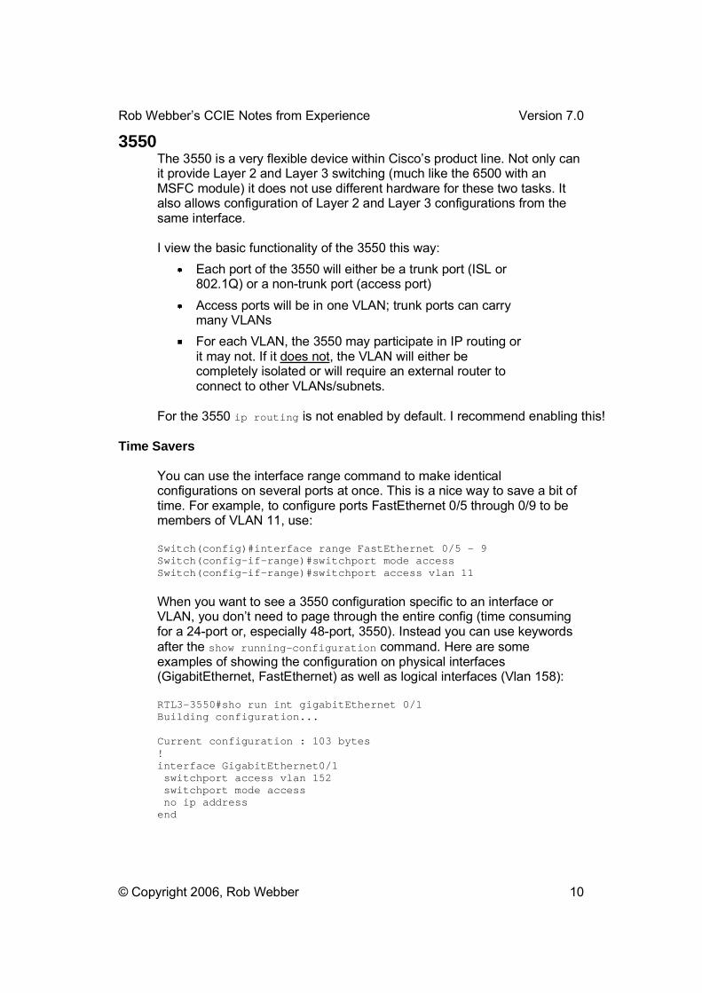
3550The 3550 is a very flexible device within Cisco�s product line. Not only can it provide Layer 2 and Layer 3 switching (much like the 6500 with an MSFC module) it does not use different hardware for these two tasks. It also allows configuration of Layer 2 and Layer 3 configurations from the same interface.
I view the basic functionality of the 3550 this way: Each port of the 3550 will either be a trunk port (ISL or 802.1Q) or a non-trunk port (access port) Access ports will be in one VLAN; trunk ports can carry many VLANs For each VLAN, the 3550 may participate in IP routing or it may not. If it does not, the VLAN will either be completely isolated or will require an external router to connect to other VLANs/subnets.
For the 3550 ip routing is not enabled by default. I recommend enabling this!
Time Savers
You can use the interface range command to make identical configurations on several ports at once. This is a nice way to save a bit of time. For example, to configure ports FastEthernet 0/5 through 0/9 to be members of VLAN 11, use:
Switch(config)#interface range FastEthernet 0/5 – 9 Switch(config-if-range)#switchport mode access Switch(config-if-range)#switchport access vlan 11
When you want to see a 3550 configuration specific to an interface or VLAN, you don�t need to page through the entire config (time consuming for a 24-port or, especially 48-port, 3550). Instead you can use keywords after the show running-configuration command. Here are some examples of showing the configuration on physical interfaces (GigabitEthernet, FastEthernet) as well as logical interfaces (Vlan 158):
RTL3-3550#sho run int gigabitEthernet 0/1 Building configuration...
Current configuration : 103 bytes !interface GigabitEthernet0/1 switchport access vlan 152 switchport mode access no ip address end
Rob Webber�s CCIE Notes from Experience Version 7.0
© Copyright 2006, Rob Webber 11
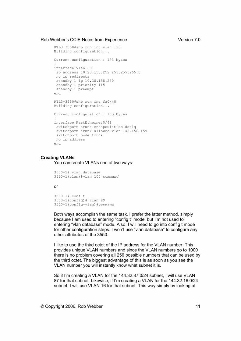
RTL3-3550#sho run int vlan 158 Building configuration...
Current configuration : 153 bytes !interface Vlan158 ip address 10.20.158.252 255.255.255.0 no ip redirects standby 1 ip 10.20.158.250 standby 1 priority 115 standby 1 preempt end
RTL3-3550#sho run int fa0/48 Building configuration...
Current configuration : 153 bytes !interface FastEthernet0/48 switchport trunk encapsulation dot1q switchport trunk allowed vlan 148,156-159 switchport mode trunk no ip address end
Creating VLANs You can create VLANs one of two ways:
3550-1# vlan database 3550-1(vlan)#vlan 100 command
or
3550-1# conf t 3550-1(config)# vlan 99 3550-1(config-vlan)#command
Both ways accomplish the same task. I prefer the latter method, simply because I am used to entering �config t� mode, but I�m not used to entering �vlan database� mode. Also, I will need to go into config t mode for other configuration steps. I won�t use �vlan database� to configure any other attributes of the 3550.
I like to use the third octet of the IP address for the VLAN number. This provides unique VLAN numbers and since the VLAN numbers go to 1000 there is no problem covering all 256 possible numbers that can be used by the third octet. The biggest advantage of this is as soon as you see the VLAN number you will instantly know what subnet it is.
So if I�m creating a VLAN for the 144.32.87.0/24 subnet, I will use VLAN 87 for that subnet. Likewise, if I�m creating a VLAN for the 144.32.16.0/24 subnet, I will use VLAN 16 for that subnet. This way simply by looking at
Rob Webber�s CCIE Notes from Experience Version 7.0
© Copyright 2006, Rob Webber 12
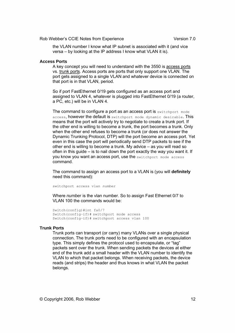
the VLAN number I know what IP subnet is associated with it (and vice versa � by looking at the IP address I know what VLAN it is).
Access Ports A key concept you will need to understand with the 3550 is access portsvs. trunk ports. Access ports are ports that only support one VLAN. The port gets assigned to a single VLAN and whatever device is connected on that port is in that VLAN, period.
So if port FastEthernet 0/19 gets configured as an access port and assigned to VLAN 4, whatever is plugged into FastEthernet 0/19 (a router, a PC, etc.) will be in VLAN 4.
The command to configure a port as an access port is switchport mode access, however the default is switchport mode dynamic desirable. This means that the port will actively try to negotiate to create a trunk port. If the other end is willing to become a trunk, the port becomes a trunk. Only when the other end refuses to become a trunk (or does not answer the Dynamic Trunking Protocol, DTP) will the port become an access port. Yet even in this case the port will periodically send DTP packets to see if the other end is willing to become a trunk. My advice � as you will read so often in this guide � is to nail down the port exactly the way you want it. If you know you want an access port, use the switchport mode accesscommand.
The command to assign an access port to a VLAN is (you will definitelyneed this command):
switchport access vlan number
Where number is the vlan number. So to assign Fast Ethernet 0/7 to VLAN 100 the commands would be:
Switch(config)#int fa0/7 Switch(config-if)# switchport mode access Switch(config-if)# switchport access vlan 100
Trunk Ports Trunk ports can transport (or carry) many VLANs over a single physical connection. The trunk ports need to be configured with an encapsulation type. This simply defines the protocol used to encapsulate, or �tag� packets sent over the trunk. When sending packets the devices at either end of the trunk add a small header with the VLAN number to identify the VLAN to which that packet belongs. When receiving packets, the device reads (and strips) the header and thus knows in what VLAN the packet belongs.

Rob Webber�s CCIE Notes from Experience Version 7.0
© Copyright 2006, Rob Webber 13
The 3550 supports both ISL and dot1q (802.1Q) trunk encapsulation types. Both work equally well; I personally prefer dot1q simply because it is an industry standard and thus it is my preferred choice in the �real� world. You need to set the trunk encapsulation type on a port before configuring it as a trunk. So to configure FastEthernet 0/3 as a trunk using 802.1Q:
Switch(config)#int fa0/3 Switch(config-if)#switchport trunk encapsulation dot1qSwitch(config-if)#switchport mode trunk
You can configure a port to dynamically negotiate a trunk connection. For example, switchport mode dynamic auto will create a trunk port if the device at the other end of the link wants to create a trunk. Similarly, switchport mode dynamic desirable will try to create a trunk with the device at the other end of the link, yet it will bring up a non-trunk connection if the device at the other end refuses to create a trunk.
As with other similar things in the CCIE lab, I recommend against using any type of auto-negotiation. I much prefer to �hard� configure both ends of the link as a trunk. That way you�ll know for sure that you are not experiencing any type of negotiation problems. If the trunk link does not come up right away, you won�t have any questions in your mind about whether there is a negotiation problem. Let�s face it � on the exam if you know a particular link needs to be a trunk, you�re probably better off having it not work at all than having it negotiate to be a non-trunk link. That way you can troubleshoot it right away (since it will be down) and not have the link working, but only passing one VLAN (in a non-trunk mode).
Restricting VLANs on Trunk Ports By default all VLANs on a given 3550 will be allowed on a trunk port. That is, if you have configured VLANs 2, 10, 11, 12, 40, 41 and 103 on a 3550, all of those VLANs will be allowed to pass along the trunk. The exam may require that you restrict what VLANs are allowed on the trunk. They may specify what VLANs are allowed, or they may state that you should only allow VLANs on the trunk that are required for the network to work.
Either way you will need the switchport trunk allowed vlan command. So to allow VLANs 2, 10, 11, 12 and 103 on a given trunk port, use the following command. Note that you cannot use any spaces between the VLANs (or VLAN ranges) when you issue this command!
switchport trunk allowed vlan 2,10-12,103
If at a later time you need to add VLAN 40, you can either list all the VLANs you would like allowed (probably a good idea so you know exactly what VLANs will be traversing the trunk) or use the �add� command:
Rob Webber�s CCIE Notes from Experience Version 7.0
© Copyright 2006, Rob Webber 14
switchport trunk allowed vlan 2,10-12,40,103
or
switchport trunk allowed vlan add 40
Note that you cannot use the command:
switchport trunk allowed vlan 40
to add VLAN 40 to the allowed list as instead this will only allow VLAN 40.
To remove VLAN 12 from a trunk (once you have already allowed it, or if the port is in the default mode, where all VLANs are allowed on the port):
switchport trunk allowed vlan remove 12
Routing with the 3550 The 3550 can route in one of two ways. I describe these two methods as �physical� routing vs. �logical� routing. Physical routing applies an IP address to one physical port. This method has the restriction that only one3550 port can be a member of that IP subnet:
interface FastEthernet0/23 no switchport ip address 155.182.32.15 255.255.255.0
Each port that is configured for physical routing acts like a port on a traditional router � it gets assigned a unique IP subnet and it is the onlyport on the 3550 that is a member of that subnet. These ports do not get assigned to any VLAN since they are �standalone� router ports. Cisco refers to these ports as �routed ports.�
Logical routing places any number of ports into a VLAN (IP subnet), then creates a logical (virtual) routed interface for that entire VLAN. This method can be used regardless of the number of ports in the VLAN � you can have one port or dozens of ports in the VLAN. Another advantage of this type of routing is ports can easily be added or removed from the VLAN/subnet with the switchport mode access command:
interface FastEthernet0/23 switchport access vlan 32 switchport mode access no ip address !interface Vlan32 ip address 155.182.32.16 255.255.255.0
Note that the VLAN assigned to the ports (vlan 32) exactly matches the interface name (Vlan32). This is what ties the router interface to the

Rob Webber�s CCIE Notes from Experience Version 7.0
© Copyright 2006, Rob Webber 15
physical ports. Cisco refers to these as �Switched Virtual Interfaces (SVI’s).� Don�t let this fancy name intimidate you � it is simply a collection of ports in a Layer 2 VLAN, with a connection to the router portion of the 3550. Figure 1: Switched Virtual Interfaces (SVI's) for the 3550 (Logical Routing) shows a logical view of how the 3550 router function and the physical RJ-45 ports of the 3550 tie together using SVI�s.
Internal RouterFunction in the 3550
VLAN 8subnet 147.142.8.0
RJ45
RJ45
RJ45
Interface Fast Eth 0/1 switchport access vlan 3 RJ
45
RJ45
RJ45
RJ45
Interface Vlan3 ip address 147.142.3.1
Interface Vlan8 ip address 147.142.8.1
Logical "SVI" Interfaces
Physical Interfaces
Interface Fast Eth 0/2 switchport access vlan 3
Interface Fast Eth 0/10 switchport access vlan 3
Interface Fast Eth 0/20 switchport access vlan 8
Interface Fast Eth 0/21 switchport access vlan 8
Interface Fast Eth 0/17 switchport access vlan 8
Interface Fast Eth 0/8 switchport access vlan 8
Figure 1: Switched Virtual Interfaces (SVI's) for the 3550 (Logical Routing)
Although both methods (physical routing and logical routing) work well, I prefer to use logical routing (SVI�s) for all my routing, even if only a single port is in a VLAN (a case where physical routing would work). Here are my reasons for always using logical routing (even though in a few cases it may require an additional command or two):
1. Logical routing covers all situations � where there is one port in a VLAN and where multiple ports are in a VLAN (IP subnet). Physical routing is limited to only one port in an IP subnet.
2. Logical routing allows additional ports to be added to a VLAN/subnet at a later time. In order to add ports to a subnet that is physically routed, you need to first convert it to logical routing � a bit of a hassle (especially under the pressure of the exam)!
3. Logical routing is very similar to the routing used by the 5500/RSM platform and the 6500/MSFC platform. If you have any experience with these products you will find logical routing almost identical.
4. I can be completely consistent using logical routing � I can use it for routing on all my VLAN/subnets. If I use physical routing in some cases I�ll almost surely also need logical routing in other cases. In that case I need to work with both types. I find it easier to simply deal with one type of routing!
As with so many things on the CCIE exam, you should select your preferred way, but know how to configure the solution both ways.
Rob Webber�s CCIE Notes from Experience Version 7.0
© Copyright 2006, Rob Webber 16
EtherchannelsWhen creating Etherchannel connections in the 3550, you can create layer 2 or layer 3 Etherchannels. I recommend using layer 2 Etherchannels, simply because they are a bit simpler and because they are more similar to other Etherchannels you may have seen, such as with the 5500 or 6500. Furthermore the difference is similar to the routing discussed in the previous section, Routing with the 3550. That is, Layer 2 Etherchannels get assigned to a VLAN (or as a trunk with several VLANs). Other ports can at any time be added to any of the VLANs, even if they will not be part of the Etherchannel. With Layer 2 Etherchannels you perform routing just as you would any Layer 2 VLAN (with the interfaceVlanxx command). Layer 3 Etherchannels do not get assigned to a VLAN and only provide a point-to-point routed link, similar to the physical routing discussed earlier.
If I know I�m creating an Etherchannel (which you will), I set the Etherchannel mode to �on� rather than �auto� or �desirable� with the channel-group 8 mode on command. Although desirable should work fine, I prefer �nailing� the Etherchannel on if I know I need it.
Make sure all the Etherchannel ports are configured the same � including VLAN(s), speed & duplex, trunking, Spanning Tree, etc.
I don�t recommend spending a lot of time understanding the underlying Etherchannel protocols � either Port Aggregation Protocol (PAgP) or the Link Aggregation Control Protocol (LACP). They are interesting to read, but so is War and Peace yet it isn�t going to help you on the exam very much. Rarely, if ever, have I had the need to configure or troubleshoot these protocols. I recommend spending a small amount of time reviewing their attributes that can be configured (just so you will have seen them), but spend the bulk of your Etherchannel time practicing Layer 2 (and Layer 3) Etherchannels.
VTPThe VLAN Trunking Protocol (VTP) is used to propagate VLAN information between 3550�s. VTP automatically propagates this information from the VTP server to all VTP clients. VTP is not required � VLANs can be defined manually on each switch. In fact, this is my preference. If I need VLAN 5 on 3550-1 and on 3550-2 I would prefer to manually create it on each switch and assign the appropriate ports to it (in this case the switches would be configured to not participate in VTP with the vtp mode transparent command).
However you may be asked to use VTP on the exam. In that case it is important to identify the switch that will be the VTP server. The exam may choose for you or you may be allowed to pick a switch. In that case the

Rob Webber�s CCIE Notes from Experience Version 7.0
© Copyright 2006, Rob Webber 17
actual switch selected is not particularly important � just remember to create and modify VLANs on that switch. It will propagate updates to all other VTP clients in the same VTP domain (share the same vtp domain domain-name command). Although a VTP client switch will learn its VTP domain name via VTP advertisements received on a trunk link, I prefer to configure the VTP domain name on each switch. This eliminates any question or doubt about the VTP domain. Just make sure that the switches are configured with the identical VTP domain name, otherwise they will not exchange information.
As discussed earlier, remember that any switch configured for VTP transparent mode (vtp mode transparent) will not send or receive VTP updates. All VLAN information needs to be configured manually on these switches.
VTP commands can be entered in global configuration mode (config t) or VLAN mode (vlan database). Global configuration mode offers a few (rarely used) additional commands.
VTP can be protected with the vtp password password command. Although this is not often used in real life, you may be required to use this on the exam.
3550 Connection Types Based on this functionality, there are several �ways� the 3550 can be used, especially on the CCIE exam. Listed below are four basic �connection types� the 3550 can employ:
1. The 3550 can be used to create a Layer 2 VLAN made up of access ports in which it does not participate in routing. This is the equivalent of the 3550 acting like a 2900 switch.
2. The 3550 can be used to create Layer 2 VLANs made up of access ports and trunk ports, where the 3550 does not participate in routing. The trunk ports will connect to another device that also supports trunking. This allows an external router, such as a 3600, to connect to several VLANs via a single physical connection.
3. The 3550 can be used to route (i.e., a �Layer 3 VLAN�) using access ports only. This is similar to connection type #1, but here the 3550 participates in and performs routing.
4. The 3550 can be used to route (i.e., a �Layer 3 VLAN�) using access and trunk ports. This is similar to connection type #2, but here the 3550 participates in and performs routing.
Example of Using the 3550 Here is an example of using the 3550 for all four �connection types� (discussed in the previous section). I always make note of the physical connectivity (how devices are cabled together) vs. the logical connectivity (what devices are on what subnets).

Rob Webber�s CCIE Notes from Experience Version 7.0
© Copyright 2006, Rob Webber 18
In the lab you may find it useful to draw both diagrams so you clearly understand both how the devices are cabled as well as what subnets they share. On the logical diagram you may also want to add the port and/or interface used by each device. I have omitted these simply because I didn�t want to clutter this diagram.
Figure 2: Typical 3550 Connectivity (Physical) and Figure 3: Typical 3550 Connectivity (Logical) show how a 3550 can be connected to utilize all four �connection types�:
The 3550 provides a simple Layer 2 VLAN (VLAN 192) for r5 and r6 (connection type 1).
The 3550 provides a Layer 2 VLAN (VLAN 64) for r4 and r14, though r4 connects with an access port and r14 connects via a trunk port (connection type 2).
The 3550 provides a VLAN (VLAN 32) for r13 and r16 (itself) using access ports on which it also routes (connection type 3).
Finally the 3550 provides a VLAN (VLAN 128) for r14 and r16 (itself) using a trunk port on which it also routes (connection type 4).
r5 r6
r43550(r16)r13
r14
trunkVLAN 64155.182.64.0/24VLAN 128155.182.128.0/24
VLAN 192155.182.192.0/24
VLAN 192155.182.192.0/24
VLAN 32155.182.32.0/24
3550 Physical Diagram
FA 0/4FA 0/23
FA 0/14
FA 0/5 FA 0/6
Figure 2: Typical 3550 Connectivity (Physical)

Rob Webber�s CCIE Notes from Experience Version 7.0
© Copyright 2006, Rob Webber 19
VLAN 192155.182.192.0/24
r5r6
r43550 (r16)r13
r14
3550 Logical Diagram
VLAN 64155.182.64.0/24
VLAN 32155.182.32.0/24
connectiontype 1
connectiontype 2
connectiontype 3
connectiontype 4
Figure 3: Typical 3550 Connectivity (Logical)
You should be familiar with each of these types of connectivity. The configurations for each device are included after the diagram. Note how the VLAN number equals the third octet of the IP subnet and how the forth octet of the IP address is the same as the router number.
Here are the configurations from each device in the figures above:
hostname 3550-r16 interface FastEthernet0/4 switchport access vlan 64 no ip address !interface FastEthernet0/5 switchport access vlan 192 no ip address !interface FastEthernet0/6 switchport access vlan 192 no ip address !interface FastEthernet0/14 switchport trunk encapsulation dot1q switchport mode trunk no ip address !interface FastEthernet0/23 switchport access vlan 32 switchport mode access no ip address !

Rob Webber�s CCIE Notes from Experience Version 7.0
© Copyright 2006, Rob Webber 20
interface Vlan32 ip address 155.182.32.16 255.255.255.0 !interface Vlan128 ip address 155.182.128.16 255.255.255.0
hostname r5 interface Ethernet0 ip address 155.182.192.5 255.255.255.0
hostname r6 interface Ethernet0 ip address 155.182.192.6 255.255.255.0 !interface Serial0 ip address 155.182.160.6 255.255.255.0
hostname r4 interface Ethernet0 ip address 155.182.64.4 255.255.255.0 !interface Serial0 ip address 155.182.160.4 255.255.255.0
hostname r13 interface Ethernet1/0 ip address 155.182.32.13 255.255.255.0 half-duplex !interface Serial1/1 ip address 155.182.16.13 255.255.255.0 clockrate 1000000
hostname r14 interface FastEthernet0/0 no ip address !interface FastEthernet0/0.64 encapsulation dot1Q 64 ip address 155.182.64.14 255.255.255.0 !interface FastEthernet0/0.128 encapsulation dot1Q 128 ip address 155.182.128.14 255.255.255.0 !interface Serial1/1 ip address 155.182.16.14 255.255.255.0
The 3550 is a complex and powerful device. I highly recommend taking some time to read the configuration guide and command reference thoroughly. Make sure you have some hands-on experience!
BGP
Peers
Rob Webber�s CCIE Notes from Experience Version 7.0
© Copyright 2006, Rob Webber 21
BGP uses two types of peers: internal BGP (iBGP) peers and external BGP (eBGP) peers. Internal peers are BGP peers that are in the same Autonomous System (AS). External BGP peers are peers that are in different Autonomous Systems.
By default eBGP peers must define each other as neighbors using the subnet that directly connects them. If either one or both do not use this �directly connected� address (if either one or both use their loopback addresses or if they are separated by a few hops) they must use the ebgp-multihop neighbor command.
By default iBGP peers can be up to 255 hops away without requiring the ebgp-multihop command.
If BGP peers (eBGP or iBGP) peer between loopback addresses they will also need the update-source neighbor command. This instructs the local router to update its BGP source IP address with the interface specified (such as loopback 0). Otherwise by default the router uses the IP address of the outgoing interface used to reach the BGP peer as its BGP source address. If you are peering between loopback addresses, this address will not match the IP address defined at the remote peer via the neighbor command. This mismatch will prevent the BGP peer relationship from forming.
Advertising to Peers If a router is originating a route with the network command, the exactnetwork and mask specified must be in that router�s routing table. This is worth noting � and it becomes especially important when attempting to advertise a summary. If the router has networks 172.16.16.0/24 through 172.16.19.0/24 in its routing table these can be advertised by one summary advertisement (172.16.16.0/22). However if you simply enter:
router bgp 65000 network 172.16.16.0 mask 255.255.252.0
The router will not advertise the summary nor any of the four class C subnets. This is because you have stated to only advertise the summary, yet the router does not have that exact network and mask in its routing table. This can be overcome with the aggregate-address command (see the Aggregate Address example on page 117) or with a static route to null0. For the latter technique, simply place a static route in the routing table to act as a placeholder so BGP will advertise a route. So you could enter:
ip route 172.16.16.0 255.255.252.0 null0 router bgp 65000 network 172.16.16.0 mask 255.255.252.0

Rob Webber�s CCIE Notes from Experience Version 7.0
© Copyright 2006, Rob Webber 22
In this case the router will advertise the summary 172.16.16.0/22 (since it is now in its routing table). When actual traffic reaches this router it will have a valid route pointing to null0, yet it will also have four more specific (in this case /24) routes in its routing table. More specific routes alwaystake precedence over less specific routes, so the traffic will get routed correctly.
Make sure you check carefully if static routes to null0 are allowed in order to use this approach.
Rob Webber�s CCIE Notes from Experience Version 7.0
© Copyright 2006, Rob Webber 23
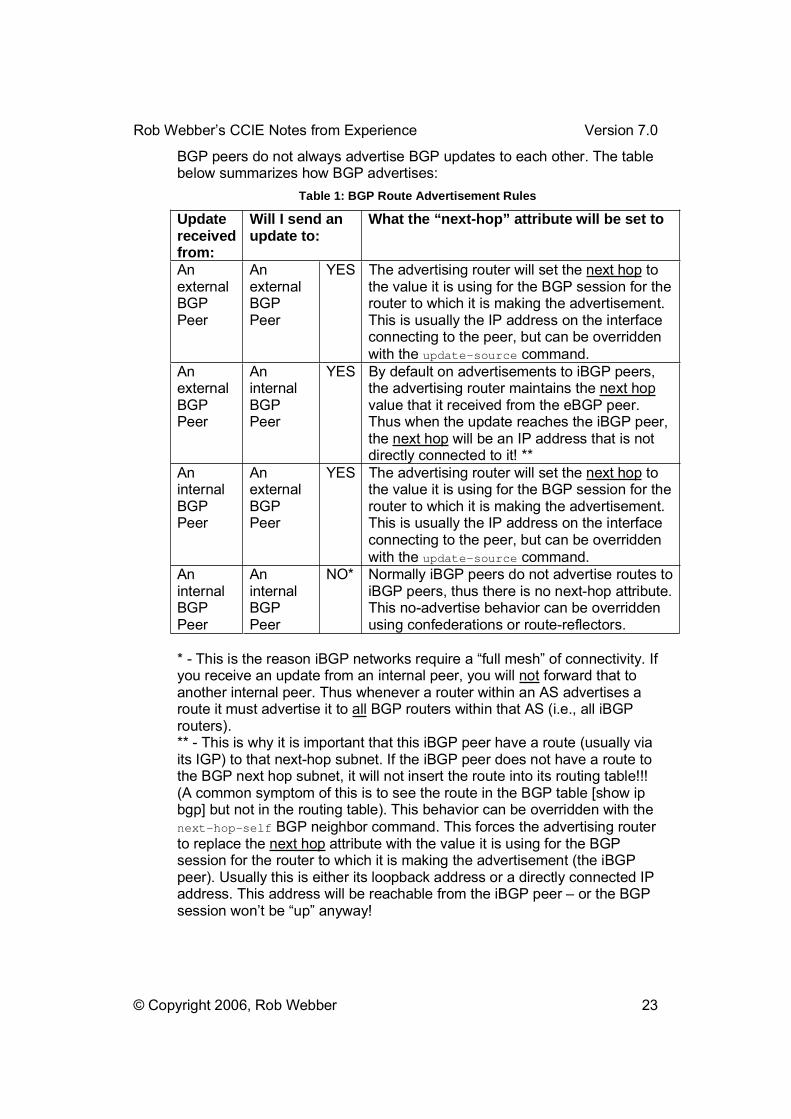
BGP peers do not always advertise BGP updates to each other. The table below summarizes how BGP advertises:
Table 1: BGP Route Advertisement Rules
Updatereceivedfrom:
Will I send an update to:
What the “next-hop” attribute will be set to
AnexternalBGPPeer
AnexternalBGPPeer
YES The advertising router will set the next hop to the value it is using for the BGP session for the router to which it is making the advertisement. This is usually the IP address on the interface connecting to the peer, but can be overridden with the update-source command.
AnexternalBGPPeer
AninternalBGPPeer
YES By default on advertisements to iBGP peers, the advertising router maintains the next hopvalue that it received from the eBGP peer. Thus when the update reaches the iBGP peer, the next hop will be an IP address that is not directly connected to it! **
AninternalBGPPeer
AnexternalBGPPeer
YES The advertising router will set the next hop to the value it is using for the BGP session for the router to which it is making the advertisement. This is usually the IP address on the interface connecting to the peer, but can be overridden with the update-source command.
AninternalBGPPeer
AninternalBGPPeer
NO* Normally iBGP peers do not advertise routes to iBGP peers, thus there is no next-hop attribute. This no-advertise behavior can be overridden using confederations or route-reflectors.
* - This is the reason iBGP networks require a �full mesh� of connectivity. If you receive an update from an internal peer, you will not forward that to another internal peer. Thus whenever a router within an AS advertises a route it must advertise it to all BGP routers within that AS (i.e., all iBGP routers).** - This is why it is important that this iBGP peer have a route (usually via its IGP) to that next-hop subnet. If the iBGP peer does not have a route to the BGP next hop subnet, it will not insert the route into its routing table!!! (A common symptom of this is to see the route in the BGP table [show ip bgp] but not in the routing table). This behavior can be overridden with the next-hop-self BGP neighbor command. This forces the advertising router to replace the next hop attribute with the value it is using for the BGP session for the router to which it is making the advertisement (the iBGP peer). Usually this is either its loopback address or a directly connected IP address. This address will be reachable from the iBGP peer � or the BGP session won�t be �up� anyway!

Rob Webber�s CCIE Notes from Experience Version 7.0
© Copyright 2006, Rob Webber 24
iBGP Full Mesh As briefly discussed in the previous section, internal BGP (iBGP), that is, BGP within one Autonomous System, must have a logical �full mesh� of connectivity. In other words every iBGP router must have a logical connection (a peer relationship) with every other BGP router in that AS. This requirement exists because BGP does not inherently have good loop-detection capability (especially within an AS). A physical full mesh is not required, but even a logical full mesh can become unmanageable!
There are two alternate solutions to the iBGP full mesh requirement: route reflectors and confederations.
Routers that are configured in a route reflector are collectively known as a cluster. Within the cluster, each router is either a route reflector server or a route reflector client. Typically there are either one or two route reflector servers in a cluster. There can be many (dozens if not hundreds) of clients in a route reflector cluster. Route reflector clients require no configuration. In fact they do not even realize they are in a cluster. Route reflector servers require that each client be identified with the neighbor route-reflector-client command. When route reflector servers receive routing updates from clients they forward the update to all other clients as well as to any iBGP peers they have that are not participating in the cluster. When route reflector servers receive routing updates from iBGP peers that are not participating in the cluster they forward the update to all clients but not to other iBGP peers that are not participating in the cluster.
Deploying confederations breaks an Autonomous System up into smaller Autonomous Systems called confederations. Confederations act like a hybrid between EBGP and iBGP. When exchanging routing updates with other (real) Autonomous Systems, the confederations are completely hidden (like an iBGP). Yet when exchanging routing updates between confederations, then deploy EBGP rules. That is, there is not a full mesh requirement. In fact two confederations can have one connection between them, multiple connections between them, or even no connections between them.
Route reflectors are the easier solution to implement and offer few, if any, drawbacks from the confederation solution.
FilteringAlthough there are many ways to filter with BGP, I like using route-maps with prefix lists. Part of the reason is you need to master route-maps, so this is a skill you will need anyway. Furthermore both the route-map and prefix-list can use the same, meaningful name. See the CCIE Study Sheet�BGP � Filtering with Route Maps� for an example of this.
To filter BGP routes you can use:

Rob Webber�s CCIE Notes from Experience Version 7.0
© Copyright 2006, Rob Webber 25
o neighbor route-map command with only a match ip addressstatement in the route-map
o neighbor distribute-list (applies to the neighbor specified) o distribute-list (applies to the entire BGP process) o neighbor filter-list with an ip as-path access-listo neighbor prefix-list
The first two options apply the filter to a specific neighbor. The third option applies the filter to the entire BGP process (routes learned from any neighbor). Using just a dist-list filters updates from the routing table but leaves them in the bgp table. The other two eliminate them from both.
The neighbor prefix-list command or the neighbor distribute-listcan be applied to a neighbor � but not both commands to the same neighbor. Given my preference for prefix lists, I prefer the neighborprefix-list command.
When filtering based on AS path, use the neighbor filter-listcommand. However note that using ^ (to denote the beginning of an AS path) matches the beginning of the path as it is listed in the bgp table. For example, to match:
Network Next Hop Metric LocPrf Weight Path * i3.0.0.0 137.39.23.89 1000 50 0 701 80 i
You could use the BGP show regular expression command: show ip bgp reg ^701_80_
This will show you the BGP entries that match the particular regular expression you specify (in this case, beginning with 701, followed by 80).
The BGP regular expression command (above) states that the �beginning� of the AS path must be 701 (followed by 80). Even though the true�beginning� of the AS path is 80 (that is, the route was originated from AS 80, then went through 701). The same holds true when using $ to mark the end of an AS path.
Thus to construct an AS_PATH filter, you apply the same logic:
ip as-path access-list 1 permit ^701_80_ router bgp 65123 neighbor 134.167.1.10 filter-list 1 in
CommunitiesIn order to send communities, you need to enter the neighbor 10.13.13.1 send-community command. This will send to that neighbor both: any communities that BGP routes already have (that were sent to you from

Rob Webber�s CCIE Notes from Experience Version 7.0
© Copyright 2006, Rob Webber 26
other peers and/or AS�s) as well as any communities you set with a route-map. Communities are not sent by default � they need this command!!!
In order to tag routes with communities, you need:
neighbor 192.168.1.2 send-community neighbor 192.168.1.2 route-map setcommunity out route-map setcommunity permit 10 match ip address 2 set community no-export !route-map setcommunity permit 20 !access-list 2 permit 192.168.254.0
You need the second route-map statement to send �all other� routes without communities. Also, it is helpful to use the global command ip bgp-community new-format. Otherwise your communities look really weird!
Synchronization Synchronization is a parameter that can be enabled or disabled in router bgp configuration. Synchronization requires that a BGP route must also show up in an IGP (OSPF, EIGRP, etc.) before it will be installed in the routing table. This rule was established in case some routers within a network were not running BGP. If they were not running BGP and the routes were not in the IGP, those routers would not be able to correctly forward packets because they would be �missing� routes. You can �officially� disable synchronization if either of the following are true:
1. All routers in the AS run BGP (thus there is no need to include them in the IGP)
2. The AS is not a transit AS, that is, it does not forward traffic between other Autonomous Systems (in this case it is presumed non-BGP routers will know how to correctly forward traffic since it is destined for within their Autonomous System).
My rule of thumb is to turn it off whenever possible! With it on, all iBGP learned routes must also show up in some IGP (OSPF, etc.) Even static routes are not enough! This can be very frustrating since it is not always obvious why the routes appear in the BGP table but do not appear in the routing table. A closer examination of a BGP route shows:
As you can see, the route 10.20.255.236/32 appears in the BGP table but not in the routing table:
RTL3FC22-156#sho ip bgp
Network Next Hop Metric LocPrf Weight Path * i10.20.255.236/32 10.20.250.236 0 100 0 i RTL3FC22-156#sho ip route bgp

Rob Webber�s CCIE Notes from Experience Version 7.0
© Copyright 2006, Rob Webber 27
RTL3FC22-156#
A closer examination of the BGP entry shows that the route is not synchronized (a case where synchronization is still enabled on the router):
RTL3FC22-156#sho ip bgp 10.20.255.236 BGP routing table entry for 10.20.255.236/32, version 3 Paths: (1 available, no best path) Not advertised to any peer Local 10.20.250.236 (metric 2) from 10.20.250.236 (10.20.250.236) Origin IGP, metric 0, localpref 100, valid, internal, notsynchronizedRTL3FC22-156#
Use the no synchronization command under the router BGP config to disable synchronization.
Aggregate Address This is a useful command for summarizing an address block. Use the keyword summary-only to suppress more specific routes. If this keyword is not included, the aggregate address you specify will be advertised, but the more specific routes will be as well. However to advertise a summary (an aggregate) at least one more specific route must be in the router�s BGPtable (via a network command, redistribution, etc.)
Attributes It is extremely important to understand each BGP attribute � especially the more important ones (local pref, AS_PATH, MEDs, communities). I won�t identify all the BGP attributes, but I will discuss the more common ones. I recommend further reading and a lot of hands-on practice, but here is an overview:AS_PATH � possibly the most important BGP attribute. It is a �running tally� of all the Autonomous Systems through which the advertisement has passed. This is important since (realistically) only local preference is higher in the order of route selection. This is by far the most common attribute used to determine routing on the Internet. Often routing is controlled by prepending an ASN (making the AS_PATH longer by including your own ASN several times). Local Preference � this is effectively first on the BGP route selection algorithm. It is set within an AS, it is passed to all routers in the AS yet it does not leave the AS. It controls how that AS routes traffic outbound to other AS�s. Since it is shared among all routers in an AS, all routers should agree on the local preference for each route. The higher local preference is preferred. A router can set the local preference on all routes (bgp default local-preference) or on specific routes (set local-preference via a route-map).For example, assume AS 10 has two ISP connections, ISP 1 and ISP 2. Without setting Local Preference, AS 10 will route traffic to whichever ISP

Rob Webber�s CCIE Notes from Experience Version 7.0
© Copyright 2006, Rob Webber 28
offers a shorter AS path for each route. But suppose AS 10 wants to route traffic via ISP 2 (if ISP 1 is a measured service, for example). AS 10 can set Local Preference higher on routes learned via ISP 2. This will cause routing via ISP 2 (unless a failure occurs, upon which ISP 1 will be used). See the CCIE Study Sheet on page 116 for an example config on setting local preference. Origin � Origin is an attribute that denotes how the route was first placed into BGP (or its �origin�). It is included in routing advertisements as they pass from one AS to another. It is surprisingly high on the route selection algorithm, though it is rarely used in route selection. This is because it is extremely rare to have two possible choices (paths) for a route where the origins are different. Since the two possible routes invariably started from the same AS, they almost always have the same origin. Origin of �i� means it was placed into BGP via a network statement, �?� means via redistribution and �e� means via EGP (rare). It can be set via BGP configuration, though this is not common. MEDs � the Multi-Exit Discriminator attribute is targeted for the scenario where two AS�s have multiple connections between them. In this case most other attributes will be identical � local pref, AS_PATH, origin, etc. MEDs allow as AS to influence how the other AS routes traffic to it. We say �influence� since the other AS can still set the local preference if it desires, and since local preference is higher than MEDs on the route selection algorithm, MEDs will be ignored. The lower MED (like an IGP metric) is preferred. It is sent from one AS to another AS, but the receiving AS does not send it to any other AS�s.So if AS 1 and AS 2 have two connections between them (connection x and connection y), AS 1 could set the MED on each so that the MED is lower on connection x. Assuming AS 2 does not set weight or Local Preference, traffic routed from AS 2 to AS 1 will get sent over connection x. Why would this be advantageous? Perhaps AS 1 wants traffic delivered over connection x because it is closer to the core of their network, or it connects into a more robust portion of their network. Weight � weight is the first attribute on the route selection algorithm, but I have never seen it used. Not on a practice lab, in real life � never. It is a �Cisco proprietary� attribute and is local to the router only (not passed with a routing advertisement at all). It can be set with the neighbor weight or the set weight commands�from what I�m told. Community � This attribute is sent with each routing advertisement from AS to AS. It is set with the set community route-map command. It is basically a way of identifying, or tagging certain routes. There are well known communities (such as no-export which means do not advertise this route to any other AS�s and no-advertise which means do not advertise this route to any peer (internal or external)). There are also user-defined communities. These are common within an AS to denote or identify certain features. They also can be used between AS�s, though this requires the coordination of the two AS�s. Their most common use is to identify a route

Rob Webber�s CCIE Notes from Experience Version 7.0
© Copyright 2006, Rob Webber 29
so that some action � not advertising, setting local preference, blocking completely, etc. � can be taken at some point later.
BGP Official Path Selection Process BGP has a somewhat complicated route selection algorithm (when presented with the same route from more than one peer). From the CCO, here is the �official� process. See the following section for my unofficialprocess. My unofficial process streamlines the �official� process into the most common scenarios.
1. If the next hop is inaccessible, do not consider it.
This is why it is important to have an IGP route to the next hop.
2. If the path is internal, synchronization is enabled, and the route is not in the IGP, do not consider the route.
3. Prefer the path with the largest weight (weight is a Cisco proprietary parameter).
4. If the routes have the same weight, prefer the route with the largest local preference.
5. If the routes have the same local preference, prefer the route that was originated by the local router.
For example, a route might be originated by the local router using the network bgp command, or through redistribution from an IGP.
6. If the local preference is the same, or if no route was originated by the local router, prefer the route with the shortest autonomous system path.
7. If the autonomous system path length is the same, prefer the route with the lowest origin code (IGP < EGP < INCOMPLETE).
8. If the origin codes are the same, prefer the route with the lowest Multi Exit Discriminator (MED) metric attribute.
This comparison is only done if the neighboring autonomous system is the same for all routes considered, unless bgp always-compare-med is enabled.
Note The most recent IETF decision regarding BGP MED assigns a value of infinity to the missing MED, making the route lacking the MED variable the least preferred. The default behavior of BGP routers running Cisco IOS software is to treat routes without the MED attribute as having a MED of 0, making the route lacking the MED variable the most preferred. To configure the router to conform to the IETF standard, use the bgpbestpath missing-as-worst command.
9. Prefer the external (EBGP) path over the internal (IBGP) path.
Rob Webber�s CCIE Notes from Experience Version 7.0
© Copyright 2006, Rob Webber 30
All confederation paths are considered internal paths.
10. Prefer the route that can be reached through the closest IGP neighbor (the lowest IGP metric).
This means the router will prefer the shortest internal path within the autonomous system to reach the destination (the shortest path to the BGP next-hop).
11. If the following conditions are all true, insert the route for this path into the IP routing table:
o Both the best route and this route are external.o Both the best route and this route are from the same neighboring
autonomous system. o maximum-paths is enabled.
Note EBGP load sharing can occur at this point, which means that multiple paths can be installed in the forwarding table.
12. If multipath is not enabled, prefer the route with the lowest IP address value for the BGP router ID.
The router ID is usually the highest IP address on the router or the loopback (virtual) address, but might be implementation-specific.
BGP Unofficial Path Selection Process This is derived from the �Official� Path Selection Process, but I have removed scenarios that almost never exist.
1. If the next hop is inaccessible, do not consider it.
This is why it is important to have an IGP route to the next hop address.
2. If the path is internal, synchronization is enabled, and the route is not in the IGP, do not consider the route. (So turn off synchronization!)
3. If the routes have the same weight, prefer the route with the largest local preference.
4. If the local preference is the same prefer the route with the shortest autonomous system path.
5. If the origin codes are the same, prefer the route with the lowest Multi Exit Discriminator (MED) metric attribute.
6. Prefer the external (EBGP) path over the internal (IBGP) path. 7. Prefer the route that can be reached through the closest IGP neighbor (the
lowest IGP metric).
Rob Webber�s CCIE Notes from Experience Version 7.0
© Copyright 2006, Rob Webber 31
This means the router will prefer the shortest internal path within the autonomous system to reach the destination (the shortest path to the BGP next-hop).
8. If multipath is not enabled, prefer the route with the lowest IP address value for the BGP router ID.
The router ID is usually the highest IP address on the router or the loopback (virtual) address, but might be implementation-specific.
BridgingFor bridging over Frame Relay, there are no special requirements if all interfaces are point-to-point. However for Frame Relay physical interfaces (no subinterfaces) or multipoint interfaces, you need one frame-relay map bridge dlci broadcast command for each DLCI that�s part of a physical or multipoint interface. However, note that for physical and multipoint interfaces, the router will not forward packets out the same physical or multipoint interface that bridge packets were received on (regardless of all else, including Spanning Tree)!
Spanning Tree My approach to Spanning Tree is to first identify the root bridge. In the real world this is the bridge closet to the core of my network. In the CCIE lab it will be the bridge where you want all ports forwarding. In a Frame Relay network, you want to choose this carefully (see the Frame Relay discussion in Bridging, below).
Once I have selected my root bridge I cost paths appropriately to allow the bridges to forward and block on each link as I see fit. I usually do this by lowering the default cost on a link I want to be in forwarding mode. You could raise the cost of a link you want in blocking mode, though if you ever add bridging to a link it will start with the default cost and compete with your forwarding link. If you lower the cost on your forwarding link, you can add additional links without worrying about setting path costs.
The root bridge is determined by the lowest bridge priority � set by the global bridge priority command.
On each subnet a designated bridge is elected. This is the bridge that will have the forwarding path to the root. The bridge with the lowest path cost to the root will be the designated bridge (and thus will be forwarding). In the case where two or more bridges have the exact same path cost to the root, the bridge with the lowest priority becomes the designated bridge.
The path cost is calculated by adding the �outbound� path costs of all paths (links) to the root. That is, path costs are added as you are leaving

Rob Webber�s CCIE Notes from Experience Version 7.0
© Copyright 2006, Rob Webber 32
each router on the way to the root (the path cost as you enter a router is irrelevant).
Port priority is almost never used. The only time this might be used is if two non-root bridges had redundant links between them. One of the four ports for those two links would have to block � port priority would allow you to control which one it was. If you don�t set this on any of the four, the IOS will select one to block.
Frame Relay Use caution when bridging via physical Frame Relay interfaces. A physical Frame Relay interface will not forward packets out the same interface upon which they were received, even if the packet is intended for a different DLCI.
In the diagram shown in Figure 4: Bridging Over Frame Relay router1 is not a good choice for the root of the Spanning Tree since if router1 is the root then both Frame Relay DLCIs on its Frame Relay interface will be forwarding bridging packets (because interfaces on the root bridge are never blocking). Yet router1 will not forward packets from router2 to router3 because it is the same physical interface.
A better solution would be to make router3 the root bridge. In this case the Frame Relay connection between router1 and router2 would be blocking � and thus router1 would not be required to forward packets to and from its Frame Relay interface, serial 0. Router3 could forward packets on both serial interfaces since they are separate physical interfaces.

Rob Webber�s CCIE Notes from Experience Version 7.0
© Copyright 2006, Rob Webber 33
S0 FrameRelay
router1
router2
router3
Point to PointSerial Connection
Spanning Treeroot bridge
Cannot beSpanning Tree
root bridge
Blocked bySpanning Tree
S0
S1
S0
S1
Figure 4: Bridging Over Frame Relay
DebugIf you need to use debug ip packet [detail] [access-list], remember that in some cases (depending on router and IOS version) only packets that are processed switched will get debugged. To disable fast switching (and force process switching) use no ip route-cache on each interface (especially the incoming interface for the packets in question). In a lab environment, configuring no ip route-cache has few negative affects. In a production environment, it will slow throughput since the CPU must process every packet. An example of using an access list to debug traffic between two hosts is shown below. This is helpful if there is a lot of other �stuff� going on that is causing the debug messages to clog up the screen:
router3(config)# access-list 105 permit ip host 172.31.2.2 host 172.31.201.1 router3# debug ip packet detail 105
During configuration ctrl-r will refresh the current line if a console or debug message is displayed (for example, if you are in the middle of a long configuration command and a debug message gets displayed, ctrl-r will refresh the line and redisplay the command you are working on).
Here is a sample output of debug ip packet detail:

Rob Webber�s CCIE Notes from Experience Version 7.0
© Copyright 2006, Rob Webber 34
22:21:25: IP: s=172.31.2.2 (Serial1), d=172.31.201.1 (Serial0), g=172.31.4.1, len 44, forward 22:21:25: TCP src=63491, dst=23, seq=3524010629, ack=0, win=4128 SYN22:21:25: IP: s=172.31.201.1 (Serial0), d=172.31.2.2 (Serial1), g=172.31.2.2, len 44, forward 22:21:25: TCP src=23, dst=63491, seq=363064486, ack=3524010630, win=4128 ACK SYN 22:21:28: IP: s=172.31.4.1 (Serial0), d=224.0.0.10, len 60, rcvd 2, proto=8822:21:28: IP: s=172.31.4.3 (local), d=224.0.0.10 (Serial0), len 60, sending broad/multicast, proto=88 22:21:28: IP: s=172.31.2.2 (Serial1), d=172.31.2.3, len 40, rcvd 0 22:21:28: TCP src=179, dst=11002, seq=2004487297, ack=1138433285, win=15059 ACK
From the above output several things can be learned. The first two packets are telnet packets (TCP dst and src 23) between 172.31.2.2 and 172.31.201.1. The �g=� indicates the gateway (next hop address) the router will use to forward the packet. The next two packets are EIGRP packets (protocol 88) from 172.31.4.1 and 172.31.4.3 to 224.0.0.10 (the EIGRP multicast address). On the last packet you can see the source port (src=) is 179 � this is BGP. This is a BGP session between 172.31.2.2 and 172.31.2.3.
DistanceDistance is the parameter that Cisco uses to determine what routing source to use for a given network when there is more than one choice. For example, suppose a router learns about 192.168.1.0/24 from RIP and EIGRP. Which one should it use? The answer is the routing source (routing protocol) with the lower distance.
Note that distance is only a factor when identical routes are learned by different means. For example, if 137.17.58.0/24 is learned via OSPF and 137.17.58.0/23 is learned via BGP, both will get placed into the routing table because they are different routes (because of their different subnet masks).
Note that distance takes precedence over any type of routing metric. For example, a router can learn about a RIP route with a metric of 1. It can learn about the same route via EIGRP with a metric of 2,297,856. Yet the router will prefer the EIGRP route (even though it has a much, much higher metric) since the distance of EIGRP is lower than that of RIP.
Distances can be altered, usually with a distance command within the given routing protocol. Distances can also be set when creating a static route. This is handy when you would prefer to learn about a route via a protocol, but want the static route there in case the protocol-learned route goes away.

Rob Webber�s CCIE Notes from Experience Version 7.0
© Copyright 2006, Rob Webber 35
The following commands set the administrative distance for EIGRP internal and external routes to 130 and 140, respectively:
router eigrp 1 distance eigrp 130 140
You can also set the distance on routes learned from a specific neighbor. This can be handy if you want to prefer EIGRP routes from a given neighbor. To set the distance of routes learned from neighbor 172.31.3.4 to 80, use:
router eigrp 1 distance 80 172.31.3.4
Here are what Cisco uses for distances by default: Directly connected 0 Static route 1 EIGRP Summary 5 BGP (eBGP) 20 EIGRP 90 IGRP 100 OSPF 110 ISIS 115 RIP 120 EIGRP External 170 Internal BGP 200
Distance is contained within each router. That is, routers do not share or advertise distance in any way. For simplicity, each router should be configured with the same distance commands (whenever possible). However in the CCIE lab you may be required to configure distance differently on each router. Whatever the case, distance commands only affect the router to which they are being applied (distance is not passed in routing updates, etc.)
Distribute Lists
* Try adding the word log at the end of an access-list statement to log what is happening with the access list (for example, what packets are being denied). For example, the configuration:
router rip network 172.31.0.0 distribute-list 1 in !access-list 1 deny 172.31.97.0 0.0.0.255 log
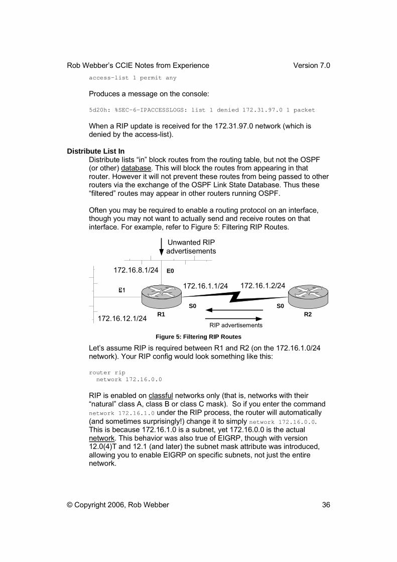
Rob Webber�s CCIE Notes from Experience Version 7.0
© Copyright 2006, Rob Webber 36
access-list 1 permit any
Produces a message on the console:
5d20h: %SEC-6-IPACCESSLOGS: list 1 denied 172.31.97.0 1 packet
When a RIP update is received for the 172.31.97.0 network (which is denied by the access-list).
Distribute List In Distribute lists �in� block routes from the routing table, but not the OSPF (or other) database. This will block the routes from appearing in that router. However it will not prevent these routes from being passed to other routers via the exchange of the OSPF Link State Database. Thus these �filtered� routes may appear in other routers running OSPF.
Often you may be required to enable a routing protocol on an interface, though you may not want to actually send and receive routes on that interface. For example, refer to Figure 5: Filtering RIP Routes.
R1
E0
R2
172.16.1.1/24 172.16.1.2/24
172.16.8.1/24
S0 S0
RIP advertisements
Unwanted RIPadvertisements
172.16.12.1/24
Figure 5: Filtering RIP Routes
Let�s assume RIP is required between R1 and R2 (on the 172.16.1.0/24 network). Your RIP config would look something like this:
router rip network 172.16.0.0
RIP is enabled on classful networks only (that is, networks with their �natural� class A, class B or class C mask). So if you enter the command network 172.16.1.0 under the RIP process, the router will automatically (and sometimes surprisingly!) change it to simply network 172.16.0.0.This is because 172.16.1.0 is a subnet, yet 172.16.0.0 is the actual network. This behavior was also true of EIGRP, though with version 12.0(4)T and 12.1 (and later) the subnet mask attribute was introduced, allowing you to enable EIGRP on specific subnets, not just the entire network.
Rob Webber�s CCIE Notes from Experience Version 7.0
© Copyright 2006, Rob Webber 37
Thus enabling RIP for the S0 interface will also enable RIP on the E0 and E1 interfaces as well. Let�s also assume that you don�t want to send or receive any routes on the E0 interface. The passive-interface E0command will prevent you from sending routing updates on that interface, but you will still receive them. An easy way to block receiving all routes on this interface is to use a distribute list:
router rip network 172.16.0.0 passive-interface e0 distribute-list 1 in e0 access-list 1 deny any
This is completely effective for blocking all incoming updates on the E0 interface. Another problem can occur from this scenario. Since RIP has been enabled on E0, by default that network will be advertised in RIP updates. In a scenario where this may not be desired, see the next section.
Distribute List Out In the network in Figure 5: Filtering RIP Routes, RIP is automatically enabled on S0, E0 and E1 by the network 172.16.0.0 command. Let�s assume there is a requirement that the only subnet in the 172.16.0.0/16 range that R2 should learn about via RIP is the 172.16.12.0/24 subnet. Distribute List out commands can control this. You can configure your access-list to:
Block the 172.16.8.0/24 route (and send all others) or Permit the 172.16.12.0/24 route (and deny all others by default).
The two scenarios are:
router rip network 172.16.0.0 distribute-list 2 out S0
With either this access-list: access-list 2 deny 172.16.8.0 access-list 2 permit any
Or this access-list: access-list 2 permit 172.16.12.0
Note
My general philosophy with filtering (in the CCIE lab) is to only allow those routes you want send. So in the above example I would select the second access-list option. The reason for my choice is this method tends to �block more stuff� than the former option, which blocks one or two specific routes and allows all others. In the lab if a particular route does not appear in a
Rob Webber�s CCIE Notes from Experience Version 7.0
© Copyright 2006, Rob Webber 38
given router, its reasonably easy to trace back through the network and find out where it is blocked � such as by a distribute-list out.
However consider the case where you configure the network using the former option (where you block 172.16.8.0/24 and allow all others). Perhaps several hours later you may choose (or be required) to add a loopback address of 172.16.100.1/24 to R1. Unless you remember to go back and block that network using access-list 2, it will propagate through your network � yet this will break the aforementioned requirement that the only subnet in the 172.16.0.0/16 range that R2 should learn about via RIP is the 172.16.12.0/24 subnet. However you may not even be aware that you�ve broken this requirement! If you select the second access-list option mentioned, 172.16.100.0/24 will be blocked automatically.
Distribute lists �out� are typically much more effective from blocking a route from a large portion of the network. However with OSPF distribute-list out only works on External Type 1 or 2 routes � not with internal OSPF routes.
Distribution lists may not take effect immediately. You may have to bounce the interface or do a clear ip route * to activate them.
The distribute-list list# out process is very tricky. For example:
2501b(config)# router ospf 103 2501b(config-router)#distribute-list 16 out eigrp 1
It would appear that this would regulate what ospf sends out to eigrp 1. But instead it controls what OSPF receives in from EIGRP 1 (or, more aptly, what EIGRP sends out to OSPF).
EIGRPBy default EIGRP will summarize routes on a classful boundary in a manner similar to RIP. I tend to dislike this behavior and disable this feature with the no auto-summary. Note that this command only affects how you advertise routes to other routers (i.e., whether or not you summarize on classful boundaries). It does not affect routes that you learn from other routers � you accept them just as they are (either classful summaries or not � depending on whether that router has auto-summary enabled or disabled). Given the choice I configure no auto-summary on all my EIGRP routers.
For NBMA topologies (Non-broadcast Multi-access, such as Frame Relay, etc.) EIGRP can have split-horizon disabled for spoke-spoke reachability. For IP, use the no ip split-horizon eigrp 1 interface command.
EIGRP Metric
Rob Webber�s CCIE Notes from Experience Version 7.0
© Copyright 2006, Rob Webber 39
When setting the EIGRP metric (via the metric keyword during redistribution or via the default-metric command) or when examining these metrics in the routing table, there are five attributes that get set (for redistributed routes) or calculated (for regular EIGRP routes):
default-metric bandwidth delay reliability loading MTU
By default reliability does not affect the metric (though this can be changed). The bandwidth is the smallest bandwidth of all links used to reach the destination network. The delay is an accumulation of the delay of all links to reach the destination network. Loading is a rough estimate of the utilization of a given link.
When I needed to set the EIGRP metric I would typically use default-metric 1000 10 255 50 1500. I would use this regardless of the actual speed, loading, etc. of the link. This approximately corresponds to 1 Mb/s of bandwidth, 100 microsecond delay, 100% reliable, 25% loaded with a 1500 byte MTU (packet size).
EIGRP Summarization EIGRP has the ability to summarize IP routes. Unlike many routing protocols, which perform summarization in the routing process configuration, EIGRP performs summarization at the interface level. The ip summary-address eigrp 1 10.20.0.0 255.255.0.0 command can be applied to an interface, such as s0. When that configuration is applied, all EIGRP routes that are within the 10.20.0.0/16 range will be summarized to one EIGRP advertisement (10.20.0.0 255.255.0.0) for advertisements outthe s0 interface. All other interfaces will not be affected by this summarization (and will advertise EIGRP routes normally).
EIGRP Default Route EIGRP cannot �generate� a default route (as OSPF can, for example, with the default-information originate command). EIGRP can accept and propagate the default route (if it is redistributed from another protocol, etc.) � it just can�t generate one when no default route exists.
EIGRP Network Commands Much like RIP, EIGRP will change networks entered into the EIGRP process with the network command unless the subnet mask is included. So the command:
RTL3FC22-156(config)#router eigrp 1 RTL3FC22-156(config-router)#network 172.17.1.0
Becomes:
router eigrp 1 network 172.17.0.0

Rob Webber�s CCIE Notes from Experience Version 7.0
© Copyright 2006, Rob Webber 40
However the command:
RTL3FC22-156(config)#router eigrp 1 RTL3FC22-156(config-router)#network 172.18.1.0 0.0.0.255
Becomes:
router eigrp 1 network 172.18.1.0 0.0.0.255
The difference is significant, as the first command will run EIGRP on all172.17.0.0 interfaces. The latter command will only run EIGRP on the 172.18.1.0 interface. Needless to say I prefer explicitly indicating the exact interfaces on which EIGRP should run by using the subnet mask. Note that it is a �reverse mask� (which I�ve never understood why Cisco uses!) like OSPF.
Frame Relay Frame Relay traffic shaping always requires a frame-relay interface-dlci command since this is where you configure the traffic shaping commands.
In Frame Relay you may want to place a map statement for your own (local) IP address so that you can ping it (or ask the proctor if this is necessary).
Interfaces and Sub-Interfaces Frame Relay PVCs can connect to a router�s physical interface, a point-to-point subinterface or a multipoint subinterface. Each has its own issues and problems as discussed in Table 2: Frame Relay Interface Types and Issues, below.
By default all DLCI�s that are announced to a router are placed in that router�s physical interface. DLCI�s can be assigned to an interface via the frame-relay interface-dlci command (preferred) or by applying a frame-relay map statement to a subinterface that references that DLCI. Due to their nature point-to-point subinterfaces can only receive one DLCI. Multipoint subinterfaces (and physical interfaces) can receive many DLCIs.
Point-to-point subinterfaces are by far the simplest. Each one is a unique IP subnet. They appear to the router as a direct link (like a physical point-to-point link, a T1 running PPP or HDLC, for example) so there are few issues with reachability, mapping, inverse arp, split horizon, etc. Because they are so easy to deal with don�t expect to see a lot of these on the lab exam!

Rob Webber�s CCIE Notes from Experience Version 7.0
© Copyright 2006, Rob Webber 41
It is possible to mix interfaces on a router (have a router connecting to a Frame Relay cloud where the router uses a combination of physical, multipoint and point-to-point subinterfaces. Although this is unusual you should practice this at least a few times!
PVC Status If you see a PVC with the status of �deleted,� it probably means you typed in a frame-relay interface-dlci 100 command, but the frame switch is not announcing (and doesn�t know about) that DLCI � check DLCI.
If you see a PVC with the status of �inactive,� it probably means the local router�s connection to the frame switch is fine, but there is a problem with the �far� end of the PVC. Check the router that is supposed to terminate the PVC.
Inverse Arp and Mapping
Frame Relay needs a way to connect, or map, a Layer 3 address (IP address) with a particular Frame Relay DLCI. That is, when a router attempts to forward packets to an IP address it needs to know out which virtual circuit � specified by a Frame Relay DLCI � the packet should be forwarded.
In some cases (such as where two routers are connected by a single virtual circuit, i.e., a single DLCI) the routers can use inverse-arp to determine the Layer 3 (IP) address at the opposite end of the virtual circuit. However in other cases, such as two �spoke� Frame Relay sites connected by one �hub� Frame Relay site, the two spokes can not use inverse-arp to learn each other�s Layer 3 addresses. This is because inverse-arp packets are never forwarded (in this example, they are not forwarded by the �hub� router).
In these cases it is common to manually map (define) each Layer 3 address the router may need to reach to a specific DLCI (virtual circuit). Note that this applies only to physical and multipoint Frame Relay interfaces. Using point-to-point sub-interfaces is an easy way to avoid doing this because a point-to-point interface can only support a single DLCI (so there is no confusion about �which� DLCI to use to reach a remote host), but when does the CCIE exam ever take the easy way?
Also, if you perform mapping on a router, it is best to create a map for every other router in the Frame cloud, including the hub router. Even if connectivity exists between that router and the hub router, if you are mapping other remote routers make a habit of mapping the hub router as well. In some versions of IOS inverse-arp is disabled once a Frame Relay (manual) mapping occurs, however the problem this poses is often not

Rob Webber�s CCIE Notes from Experience Version 7.0
© Copyright 2006, Rob Webber 42
apparent until the router is rebooted (which clears the mappings dynamically learned using inverse-arp).
The way this can occur is as follows: suppose router A is a �spoke� router connecting to router B. Router C is also a spoke router that connects to router B. Router A uses inverse-arp to map router B�s IP address to a particular DLCI. However router A can not inverse-arp for router C�s IP address as discussed. A map statement is placed in router A for router C. Everything works great since router A has the two mappings it needs: a dynamically learned one for router B (via inverse-arp) and a manually defined one (via a map statement) for router C.
However with some versions of code the map statement disables inverse-arp. Thus once the router is rebooted is loses its dynamically learned mapping for router B. Since the map statement has disabled inverse-arp, connectivity to router B is lost. Thus, to be safe if you are performing map statements add one for each router in the Frame cloud.
Table 2: Frame Relay Interface Types and Issues shows the various combination of Frame Relay interface types that can exist at the �hub� router and at the �spoke� routers. Each combination has potential problems and issues, as are outlined in the table.

Rob Webber�s CCIE Notes from Experience Version 7.0
© Copyright 2006, Rob Webber 43
Table 2: Frame Relay Interface Types and Issues
Central Site Frame Relay router
Remote Site Frame Relay router
Interface Issues Interface IssuesNosubinterfaces
May need to disable IP split horizon.
No subinterfaces Need a frame-relay map statement for all neighbors. Need ip ospf priority 0 on all remotes. Need to enable IP split horizon.
Nosubinterfaces
OSPF network type mismatch � probably have to use ip ospf network point-to-multipoint to make it work. May need to disable IP split horizon.
Point-Pointsubinterfaces
Need frame-relay interface-dlci command. OSPF network type mismatch � probably have to use ip ospf network point-to-multipoint to make it work.
Nosubinterfaces Very unlikely configuration.
May need to disable IP split horizon.
Multipoint subinterfaces
Need frame-relay interface-dlci command. Need either:
On remotes: a frame-relay map statement for all neighbors and ip ospf priority 0, or
ip ospf network point-to-multipoint everywhere.
Point-Pointsubinterfaces
Need frame-relay interface-dlci command. OSPF network type mismatch.
No subinterfaces OSPF network type mismatch � set remotes to ip ospf network point-to-point. Remotes will be on different subnets. Need to enable IP split horizon.
Point-Pointsubinterfaces
Need frame-relay interface-dlci command.
Point-Pointsubinterfaces
Need frame-relay interface-dlci command.
Point-Pointsubinterfaces
Need frame-relay interface-dlci command. OSPF network type mismatch.Very unlikely configuration.
Multipoint subinterfaces
Need frame-relay interface-dlci command. OSPF network type mismatch � set remotes to ip ospf network point-to-point.
Multipoint subinterfaces
Need frame-relay interface-dlci command. Need to disable IP split horizon.
No subinterfaces Need a frame-relay map statement for all neighbors. Need ip ospf priority 0 on all remotes. On 11.3 and lower, need ip ospf network point-to-multipoint or statically defined OSPF neighbors. Need to enable IP split horizon.
Multipoint subinterfaces
Need frame-relay interface-dlci command. OSPF network type mismatch � probably have to use ip ospf network point-to-multipoint to make it work. Need to disable IP split horizon.
Point-Pointsubinterfaces
Need frame-relay interface-dlci command. OSPF network type mismatch � probably have to use ip ospf network point-to-multipoint to make it work.
Multipoint subinterfaces
Need frame-relay interface-dlci command. Need to disable IP split horizon.
Very unlikely configuration.
Multipoint subinterfaces
Need frame-relay interface-dlci command. Need either:
On remotes: a frame-relay map statement for all neighbors and ip ospf priority 0, or
ip ospf network point-to-multipoint everywhere.
When configuring your frame-relay map statements, don�t forget the broadcast at the end! This allows broadcast and multicast packets to traverse the link (important).
OSPF
Rob Webber�s CCIE Notes from Experience Version 7.0
© Copyright 2006, Rob Webber 44
A Frame Relay interface (not a subinterface) defaults to OSPF network type of nonbroadcast (NBMA). If using this default non-broadcast network type, be sure to set ip ospf priority 0 on all remotes (because you want the hub router to be the designated router).
A Frame Relay point-to-point subinterface defaults to OSPF network type of point_to_point.
A Frame Relay multipoint subinterface defaults to OSPF network type of nonbroadcast (NBMA).
If you use point-to-point subinterfaces at one end of a PVC and no subinterfaces at the end, you must account for the type mismatch. For example, use ip ospf network point-to-point at the end not using subinterfaces. If you use a combination of physical and multipoint subinterfaces, use ip ospf network point-to-multipoint.
Home Lab During your CCIE preparation you will need to decide whether to purchase a home lab. I highly recommend purchasing one. Unless you have access to a lab (at work, etc.) a home lab is invaluable. Not only can you work on it anytime it is convenient, you can also continue to build on configurations over several days (unlike labs where you rent rack time or equipment). Now that used 2500�s on eBay are under $200, a small home lab can be assembled at a reasonable price. At the very least I recommend purchasing some 2500�s since you can practice a fairly wide range of networking topics on these devices (OSPF, BGP, EIGRP, etc., etc.)
A home lab is a significant investment, though when I sold my lab after one year I recovered all the money I had invested in it.
Home Lab Considerations If you do decide to build a home lab, consider the following:
Try to get at least 16 MB of RAM and at least 16 MB of flash on all routers (if not more). Memory and flash upgrades can easily be purchased on ebay, though you should plan on these costs when initially buying. The 16 MB of memory is useful for running compressed images (see �IOS For Your Home Lab� below). For most 12.1 and above images you will need at least 16 MB of flash. Although 16 MB of flash is less commonly found on 2500 series routers, you could buy a second 8 MB flash SIMM, insert it in the 2500 and have 16 MB of flash. Use the partition flash 1 16 command to make the whole 16 MB usable for a single image (instead of two separate 8 MB partitions).
The CCIE exam includes the 3550 layer 3 switch. As these are somewhat new they are typically expensive. For the same reason they will also retain their value for some time. If you can afford to

Rob Webber�s CCIE Notes from Experience Version 7.0
© Copyright 2006, Rob Webber 45
purchase one it will be an advantage in your studies. If not, you should consider alternatives, such as renting rack time that includes the 3550.
I used all 2500 routers, strictly for cost considerations. The 2500�s allow you to practice most configurations and all of the �core� configurations. They do not allow you to practice some configurations (Ethernet trunking, etc.). For these technologies I rented rack time or used equipment at my local Cisco sales office.
Make sure you purchase at least one �frame switch� router. This is a router with 4 or more serial lines that can act as a Frame Relay switch. You can use a 2520, 2521, 2522, 2523, an old AGS+, etc.
Make sure you purchase a terminal server (2509, 2510, 2511, 2512, etc.) It is important that you become fluent accessing your routers via their console ports through the terminal server.
Purchase your routers on eBay. You can find out about a seller (based on their rating) and there is an ample supply (which also usually dictates reasonable pricing). Watch a few auctions of routers you are interested in to determine the market value.
IOS For Your Home Lab If you have a home lab you�ll need to select an IOS to use for each router.
On most of my routers I used c2500-is-l.122-15.T14.bin. This gave me the �IP Plus� feature set on a very stable version of 12.2. The T14 �train� contains IPv6.
For a good, general image consider c2500-jos56i-l.121-26.bin for an image. The �jos56i� is the feature set. This represents Enterprise Plus along with Firewall and IPSec software. Even though this is 12.1, this allowed me to configure IPSec, Firewall features and IP Plus features.
For routers that have a limited flash, I used a compressed image. Cisco doesn�t recommend this on production routers, though in a lab environment it works great. You do need a decent amount of memory (almost all my routers had 16 MB) but compressing an image let�s you place a 10 or 11 MB image in an 8 MB flash. You can also compress a larger image so that it will fit into 16 MB of flash.
You can compress the image with any �standard� UNIX compress utility. The router will decompress the image on boot-up (it takes a few minutes longer to boot), then it runs the image from memory. Once the router is booted you can�t tell that the image on flash was compressed.
For example, on some of my 2500 routers I only had 8 MB of flash. On these routers I ran c2500-jos56i-l.120-14.bin.Z. The �Z� at the end indicates it is compressed. Although this image is normally over 11 MB, compressed it was only 7.4 MB and fit easily into my 8 MB of flash.

Rob Webber�s CCIE Notes from Experience Version 7.0
© Copyright 2006, Rob Webber 46
Although this is definitely an older image, it contains the Enterprise Plus with Firewall and IPSec software, so I could configure most of the features the 2500 supports. I was only missing a couple of the latest features and commands. I practiced those on some of my other routers.
Remember that if you are limited in flash you don�t necessarily need everyfeature on every router. For example, you might want IPSec on certain routers, firewall features on other routers, etc.
Choosing a Terminal Emulator My strategy for terminal emulators was to use my favorite one to prepare for my lab exam, then switch to Hyperterminal 2-3 weeks before the exam just to get used to the �look and feel� of Hyperterminal (which is the default emulator for Windows).
I selected Tera Term (also known as Tera Term Pro) for my terminal emulator of choice. I recommend Tera Term as it can make your life easier. The biggest advantage of Tera Term for me was:
Tera Term uses a very simple macro language. With this you can very easily program Tera Term to execute commands on your routers. I have included two such useful Macros in Appendix A: Tera Term Macro.
For example:
I used a Tera Term macro to automatically prompt me for a filename. Once I entered it, Tera Term would go to each router and log its current config and IP routing table, then store all these configs and routing tables in a pre-determined directory using the filename I specified when it prompted me.
I found this extremely useful since it would very quickly �capture� the configs and IP routing tables (and any other info you desire � OSPF neighbors, IPSec associations, etc.) for a given scenario with virtually no effort. During my studying I was forever reviewing scenarios I had already staged in my lab. This made a very easy way to document all my work for later review.
This macro is included in �Appendix A: Tera Term Macro� for your reference. I have included my comments to attempt to explain what the macro is doing.
You could easily write a macro for other purposes, such as write-erasing your routers when changing from one lab scenario to another. Tera Term is freeware and can be found on many software distribution sites, such as www.tucows.com and www.cnet.com.
Rob Webber�s CCIE Notes from Experience Version 7.0
© Copyright 2006, Rob Webber 47
Accessing Your Lab From the Internet When I was studying for the lab exam I created a network that allowed me to connect to all my routers from anywhere on the Internet. I found this to be handy since if I was at work (or anywhere with Internet connectivity) and had a few free minutes, such as during lunch, after work, etc., I could quickly log on and begin studying. This could also allow you to share your equipment with a study partner.
I have a cable modem connection at home. I purchased a broadband router/firewall to both increase my network security and to allow several devices � such as my own laptop and my routers � to access the Internet simultaneously. I have been extremely pleased with my SMC Barricade. Here are a few broadband router/firewalls, all under $100:
Vendor ProductSMC Barricade Linksys EtherFast Cable/DSL Firewall Router D-Link 4 Port Broadband Gateway Netgear Internet Gateway Router
Here is the configuration I used for my home lab:

Rob Webber�s CCIE Notes from Experience Version 7.0
© Copyright 2006, Rob Webber 48
2509, 2511 or similarterminal server router
router1
Cable Modem, DSL router,or other broadband
Internet access device
Broadband Router/Firewall configured to:accept DHCP address from InternetNAT telnet connections to 192.168.123.10
router2
router3
asyncconnection to
the console
asyncconnection tothe console
asyncconnection to
the console
10 Mb/s Ethernet
192.168.123.10/24
192.168.123.254/24
Internet
Figure 6: Home Lab with Internet Connectivity
Automatically Logging in to All Routers
I always felt that to have to create a connection to every router in my lab was a tedious chore I hoped to automate. As I discuss in other sections of this guide I used Tera Term as my terminal emulator. Using this program I created a macro (a script) to log into all my routers. Here are my router configs:Terminal Server router:
interface loopback 0 ip address 1.1.1.1 255.255.255.255 ip host router1 1.1.1.1 2001 ip host router2 1.1.1.1 2002 ip host router3 1.1.1.1 2003
In each router: line con 0 privilege level 15 no login line vty 0 4

Rob Webber�s CCIE Notes from Experience Version 7.0
© Copyright 2006, Rob Webber 49
privilege level 15 no login
Once you are logged into your terminal server router (in enable mode), you simply invoke the script (via the Control Macro menu selection in Tera Term). Here is the script:
timeout = 120
send "router1" sendln #13 wait "#"
sendln #30#$78 wait "#" send "router2" sendln #13 wait "#"
sendln #30#$78 wait "#" send "router3" sendln #13 wait "#"
sendln #30#$78 wait "#" send "where" send #13
Simply save this as a text file, then select that file when you invoke the Tera Term script (Control Macro). You can use other names for your routers (such as r1, r2, etc.) Just simply change the config of the terminal server router (such as ip host r1 1.1.1.1 2001) and update the names in the script above.
You can repeat the portion of the script in bold for each of your routers (or other devices). The �sendln #30#$78� sends the terminal server a Ctrl-Shift-6 X to escape back to the terminal server.
If you need to use telnet and enable passwords on your routers, simply replace the bold portion of the script with:
sendln #30#$78 wait "#" send "router3" sendln #13 wait "Password:" sendln "lucy" wait ">" sendln "en"

Rob Webber�s CCIE Notes from Experience Version 7.0
© Copyright 2006, Rob Webber 50
wait "Password:" sendln "lucy" sendln #13 sendln #13 wait “#”
Don�t feel you need to use �lucy� as your password. You can use the name of your own cat!
IKEIKE is the Internet Key Exchange standard and is usually performed using the ISAKMP protocol. IKE is often used with IPSec because it automates key management and controls the security associations that are formed, though IKE is not required for IPSec. IKE policies define five things:
encryption algorithm (such as des) hash algorithm (such as sha or md5) authentication method (such as rsa-sig, rsa-encr or pre-share) Diffe-Hellman group (such as group-1 (768-bit) or group-2 (1024
bit)) security association lifetime (in seconds)
All of these have defaults (and the defaults can be used) except authentication � that must be specified. Pre-share is by far the easiest authentication method � it simply requires one command defining the same text key at each peer. Thus this is my recommendation (assuming this is allowed on the exam). Rsa-sig authentication requires a certificate authority (and thus is very unlikely to be on the CCIE Lab). These parameters affect the data that flows between hosts during the IKE negotiation � not the actual data flows. Encryption and authentication of data flows are defined by the transform set in IPSec (step 3, below).
IPSecTo configure IPSec:
Determine whether to use ISAKMP (recommended) or manual config for security associations
Configure ISAKMP (recommended) or manual IPSec Then:
1. Define the ISAKMP policy (only if using ISAKMP) 2. Define the keys (pre-shared, RSA, etc. � pre-shared is
recommended)3. Define a transform set (security configuration)4. Define an access list to determine what traffic will be sent via IPSec 5. Create crypto map entries 6. Apply the crypto map to an interface
The ISAKMP policy (encryption, authentication, length of association, etc.) applies to the exchange of keys � not to the actual data that gets passed
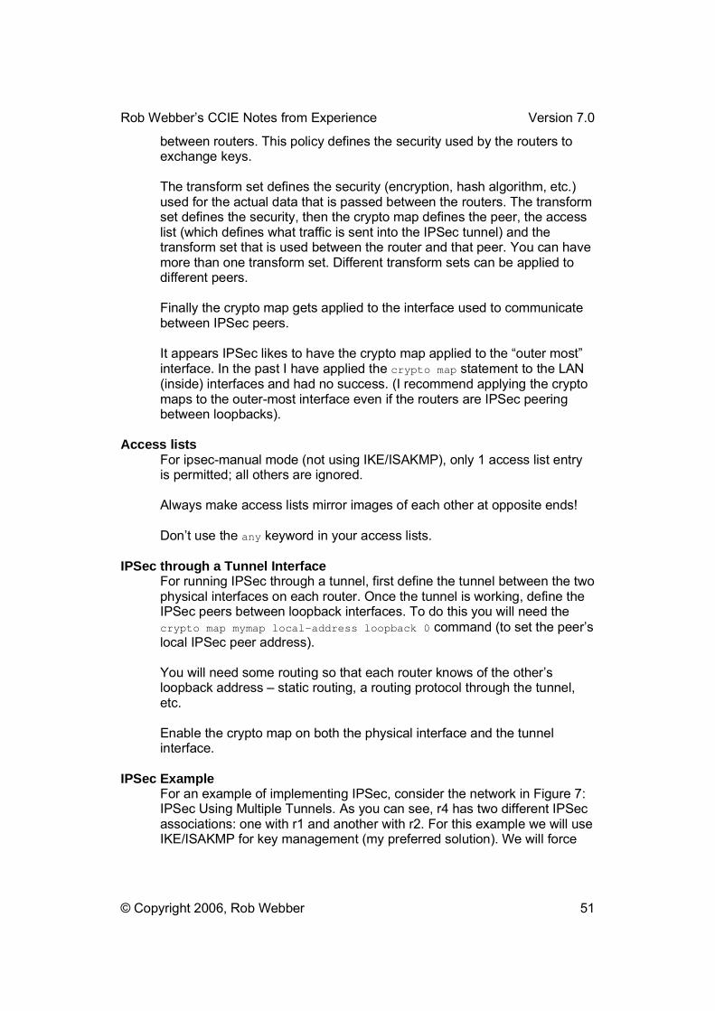
Rob Webber�s CCIE Notes from Experience Version 7.0
© Copyright 2006, Rob Webber 51
between routers. This policy defines the security used by the routers to exchange keys.
The transform set defines the security (encryption, hash algorithm, etc.) used for the actual data that is passed between the routers. The transform set defines the security, then the crypto map defines the peer, the access list (which defines what traffic is sent into the IPSec tunnel) and the transform set that is used between the router and that peer. You can have more than one transform set. Different transform sets can be applied to different peers.
Finally the crypto map gets applied to the interface used to communicate between IPSec peers.
It appears IPSec likes to have the crypto map applied to the �outer most� interface. In the past I have applied the crypto map statement to the LAN (inside) interfaces and had no success. (I recommend applying the crypto maps to the outer-most interface even if the routers are IPSec peering between loopbacks).
Access lists For ipsec-manual mode (not using IKE/ISAKMP), only 1 access list entry is permitted; all others are ignored.
Always make access lists mirror images of each other at opposite ends!
Don�t use the any keyword in your access lists.
IPSec through a Tunnel Interface For running IPSec through a tunnel, first define the tunnel between the two physical interfaces on each router. Once the tunnel is working, define the IPSec peers between loopback interfaces. To do this you will need the crypto map mymap local-address loopback 0 command (to set the peer�s local IPSec peer address).
You will need some routing so that each router knows of the other�s loopback address � static routing, a routing protocol through the tunnel, etc.
Enable the crypto map on both the physical interface and the tunnel interface.
IPSec Example For an example of implementing IPSec, consider the network in Figure 7: IPSec Using Multiple Tunnels. As you can see, r4 has two different IPSec associations: one with r1 and another with r2. For this example we will use IKE/ISAKMP for key management (my preferred solution). We will force
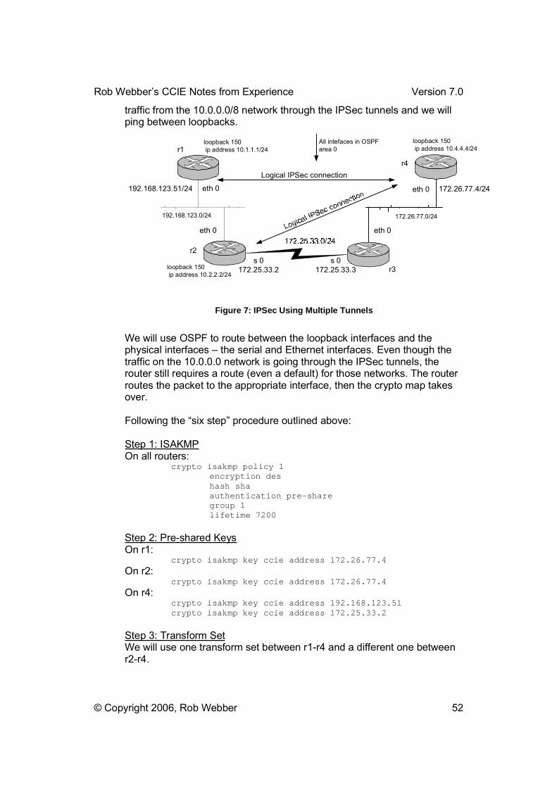
Rob Webber�s CCIE Notes from Experience Version 7.0
© Copyright 2006, Rob Webber 52
traffic from the 10.0.0.0/8 network through the IPSec tunnels and we will ping between loopbacks.
192.168.123.0/24
r1
r2
r3
r4
172.26.77.0/24
Logical IPSec connection
eth 0
eth 0
s 0172.25.33.2
s 0172.25.33.3
eth 0
eth 0
192.168.123.51/24 172.26.77.4/24
loopback 150 ip address 10.1.1.1/24
loopback 150 ip address 10.2.2.2/24
loopback 150 ip address 10.4.4.4/24
All intefaces in OSPFarea 0
Figure 7: IPSec Using Multiple Tunnels
We will use OSPF to route between the loopback interfaces and the physical interfaces � the serial and Ethernet interfaces. Even though the traffic on the 10.0.0.0 network is going through the IPSec tunnels, the router still requires a route (even a default) for those networks. The router routes the packet to the appropriate interface, then the crypto map takes over.
Following the �six step� procedure outlined above:
Step 1: ISAKMPOn all routers:
crypto isakmp policy 1 encryption des hash sha authentication pre-share group 1 lifetime 7200
Step 2: Pre-shared KeysOn r1:
crypto isakmp key ccie address 172.26.77.4 On r2:
crypto isakmp key ccie address 172.26.77.4 On r4:
crypto isakmp key ccie address 192.168.123.51 crypto isakmp key ccie address 172.25.33.2
Step 3: Transform SetWe will use one transform set between r1-r4 and a different one between r2-r4.

Rob Webber�s CCIE Notes from Experience Version 7.0
© Copyright 2006, Rob Webber 53
On r1: crypto ipsec transform-set r1-r4set esp-des esp-sha
On r2: crypto ipsec transform-set r2-r4set esp-des ah-sha-hmac
On r4: crypto ipsec transform-set r1-r4set esp-des esp-sha crypto ipsec transform-set r2-r4set esp-des ah-sha-hmac
Step 4: Access-ListOn r1:
access-list 104 permit ip 10.1.1.0 0.0.0.255 10.4.4.0 0.0.0.255 On r2:
access-list 104 permit ip 10.2.2.0 0.0.0.255 10.4.4.0 0.0.0.255 On r4:
access-list 101 permit ip 10.4.4.0 0.0.0.255 10.1.1.0 0.0.0.255 access-list 102 permit ip 10.4.4.0 0.0.0.255 10.2.2.0 0.0.0.255
Step 5: Crypto Map EntriesOn r1:
crypto map mymap 10 ipsec-isakmp match address 104 set peer 172.26.77.4 set transform-set r1-r4set
On r2: crypto map mymap 10 ipsec-isakmp match address 104 set peer 172.26.77.4 set transform-set r2-r4set
On r4: crypto map mymap 10 ipsec-isakmp match address 101 set peer 192.168.123.51 set transform-set r1-r4set crypto map mymap 20 ipsec-isakmp match address 102 set peer 172.25.33.2 set transform-set r2-r4set
Step 6: Apply the crypto map to an interface
On r1: interface Ethernet 0 crypto map mymap
On r2: interface serial 0 crypto map mymap
On r4: interface Ethernet 0 crypto map mymap
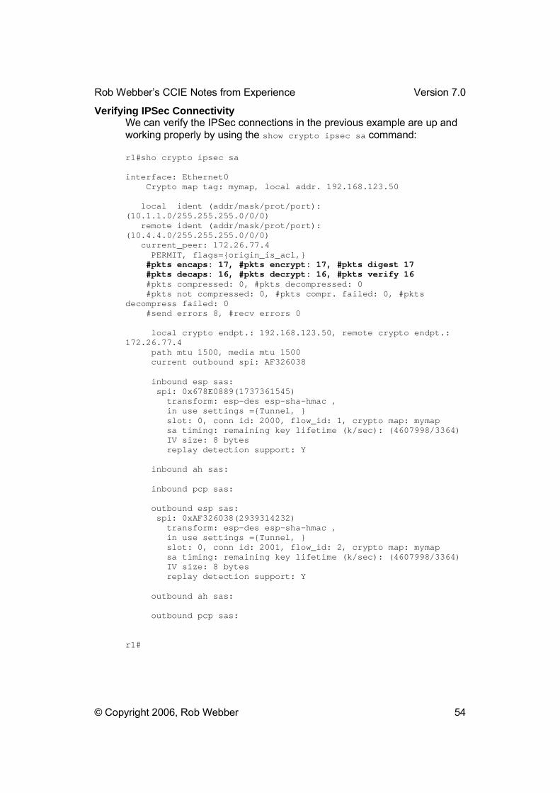
Rob Webber�s CCIE Notes from Experience Version 7.0
© Copyright 2006, Rob Webber 54
Verifying IPSec Connectivity We can verify the IPSec connections in the previous example are up and working properly by using the show crypto ipsec sa command:
r1#sho crypto ipsec sa
interface: Ethernet0 Crypto map tag: mymap, local addr. 192.168.123.50
local ident (addr/mask/prot/port): (10.1.1.0/255.255.255.0/0/0) remote ident (addr/mask/prot/port): (10.4.4.0/255.255.255.0/0/0) current_peer: 172.26.77.4 PERMIT, flags={origin_is_acl,} #pkts encaps: 17, #pkts encrypt: 17, #pkts digest 17 #pkts decaps: 16, #pkts decrypt: 16, #pkts verify 16 #pkts compressed: 0, #pkts decompressed: 0 #pkts not compressed: 0, #pkts compr. failed: 0, #pkts decompress failed: 0 #send errors 8, #recv errors 0
local crypto endpt.: 192.168.123.50, remote crypto endpt.: 172.26.77.4 path mtu 1500, media mtu 1500 current outbound spi: AF326038
inbound esp sas: spi: 0x678E0889(1737361545) transform: esp-des esp-sha-hmac , in use settings ={Tunnel, } slot: 0, conn id: 2000, flow_id: 1, crypto map: mymap sa timing: remaining key lifetime (k/sec): (4607998/3364) IV size: 8 bytes replay detection support: Y
inbound ah sas:
inbound pcp sas:
outbound esp sas: spi: 0xAF326038(2939314232) transform: esp-des esp-sha-hmac , in use settings ={Tunnel, } slot: 0, conn id: 2001, flow_id: 2, crypto map: mymap sa timing: remaining key lifetime (k/sec): (4607998/3364) IV size: 8 bytes replay detection support: Y
outbound ah sas:
outbound pcp sas:
r1#

Rob Webber�s CCIE Notes from Experience Version 7.0
© Copyright 2006, Rob Webber 55
Notice above (in bold) the traffic that has been encapsulated (in IPSec), encrypted and had a digest applied. When we ping between loopbacks we have success � these packets are all going via the IPSec connections. To verify this you can do another show crypto ipsec sa after the 25 pings. You�ll notice the traffic increases by the 25 packets:
r1#pingProtocol [ip]: Target IP address: 10.4.4.4Repeat count [5]: 25 Datagram size [100]: Timeout in seconds [2]: Extended commands [n]: y Source address or interface: 10.1.1.1Type of service [0]: Set DF bit in IP header? [no]: Validate reply data? [no]: Data pattern [0xABCD]: Loose, Strict, Record, Timestamp, Verbose[none]: Sweep range of sizes [n]: Type escape sequence to abort. Sending 25, 100-byte ICMP Echos to 10.4.4.4, timeout is 2 seconds:Packet sent with a source address of 10.1.1.1 !!!!!!!!!!!!!!!!!!!!!!!!!Success rate is 100 percent (25/25), round-trip min/avg/max = 52/53/60 ms r1#r1#r1#sho crypto ipsec sa
interface: Ethernet0 Crypto map tag: mymap, local addr. 192.168.123.50
local ident (addr/mask/prot/port): (10.1.1.0/255.255.255.0/0/0) remote ident (addr/mask/prot/port): (10.4.4.0/255.255.255.0/0/0) current_peer: 172.26.77.4 PERMIT, flags={origin_is_acl,} #pkts encaps: 42, #pkts encrypt: 42, #pkts digest 42 #pkts decaps: 41, #pkts decrypt: 41, #pkts verify 41 #pkts compressed: 0, #pkts decompressed: 0 #pkts not compressed: 0, #pkts compr. failed: 0, #pkts decompress failed: 0 #send errors 8, #recv errors 0
local crypto endpt.: 192.168.123.50, remote crypto endpt.: 172.26.77.4 path mtu 1500, media mtu 1500 current outbound spi: AF326038
inbound esp sas: spi: 0x678E0889(1737361545) transform: esp-des esp-sha-hmac , in use settings ={Tunnel, } slot: 0, conn id: 2000, flow_id: 1, crypto map: mymap

Rob Webber�s CCIE Notes from Experience Version 7.0
© Copyright 2006, Rob Webber 56
sa timing: remaining key lifetime (k/sec): (4607994/1105) IV size: 8 bytes replay detection support: Y
inbound ah sas:
inbound pcp sas:
outbound esp sas: spi: 0xAF326038(2939314232) transform: esp-des esp-sha-hmac , in use settings ={Tunnel, } slot: 0, conn id: 2001, flow_id: 2, crypto map: mymap sa timing: remaining key lifetime (k/sec): (4607994/1105) IV size: 8 bytes replay detection support: Y
outbound ah sas:
outbound pcp sas:
r1#
Performing a sho crypto isakmp sa displays that the two routers have successfully made an ISAKMP connection:
r1#sho crypto isakmp sa dst src state conn-id slot 172.26.77.4 192.168.123.50 QM_IDLE 1 0
r1#
The final router configs from the example in Figure 7: IPSec Using Multiple Tunnels:r1crypto isakmp policy 1 encryption des hash sha authentication pre-share group 1 lifetime 7200 crypto isakmp key ccie address 172.26.77.4 crypto ipsec transform-set r1-r4set esp-des esp-sha crypto map mymap 10 ipsec-isakmp match address 104 set peer 172.26.77.4 set transform-set r1-r4set interface loopback 150 ip address 10.1.1.1 255.255.255.0 interface Ethernet 0 ip address 192.168.123.50 255.255.255.0 crypto map mymap router ospf 1 network 192.168.123.0 0.0.0.255 area 0 network 10.1.1.0 0.0.0.255 area 0
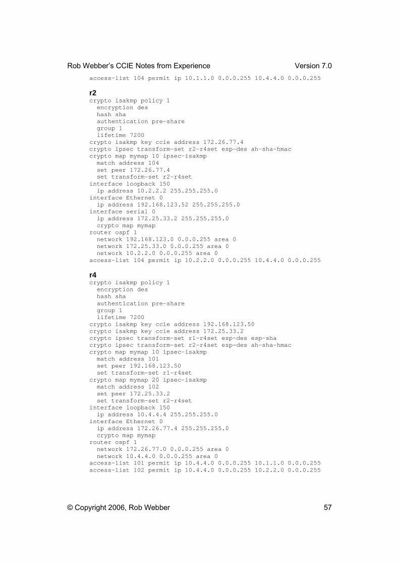
Rob Webber�s CCIE Notes from Experience Version 7.0
© Copyright 2006, Rob Webber 57
access-list 104 permit ip 10.1.1.0 0.0.0.255 10.4.4.0 0.0.0.255
r2crypto isakmp policy 1 encryption des hash sha authentication pre-share group 1 lifetime 7200 crypto isakmp key ccie address 172.26.77.4 crypto ipsec transform-set r2-r4set esp-des ah-sha-hmac crypto map mymap 10 ipsec-isakmp match address 104 set peer 172.26.77.4 set transform-set r2-r4set interface loopback 150 ip address 10.2.2.2 255.255.255.0 interface Ethernet 0 ip address 192.168.123.52 255.255.255.0 interface serial 0 ip address 172.25.33.2 255.255.255.0 crypto map mymap router ospf 1 network 192.168.123.0 0.0.0.255 area 0 network 172.25.33.0 0.0.0.255 area 0 network 10.2.2.0 0.0.0.255 area 0 access-list 104 permit ip 10.2.2.0 0.0.0.255 10.4.4.0 0.0.0.255
r4crypto isakmp policy 1 encryption des hash sha authentication pre-share group 1 lifetime 7200 crypto isakmp key ccie address 192.168.123.50 crypto isakmp key ccie address 172.25.33.2 crypto ipsec transform-set r1-r4set esp-des esp-sha crypto ipsec transform-set r2-r4set esp-des ah-sha-hmac crypto map mymap 10 ipsec-isakmp match address 101 set peer 192.168.123.50 set transform-set r1-r4set crypto map mymap 20 ipsec-isakmp match address 102 set peer 172.25.33.2 set transform-set r2-r4set interface loopback 150 ip address 10.4.4.4 255.255.255.0 interface Ethernet 0 ip address 172.26.77.4 255.255.255.0 crypto map mymap router ospf 1 network 172.26.77.0 0.0.0.255 area 0 network 10.4.4.0 0.0.0.255 area 0 access-list 101 permit ip 10.4.4.0 0.0.0.255 10.1.1.0 0.0.0.255 access-list 102 permit ip 10.4.4.0 0.0.0.255 10.2.2.0 0.0.0.255

Rob Webber�s CCIE Notes from Experience Version 7.0
© Copyright 2006, Rob Webber 58
IPv6With version 12.2 of IOS, Cisco has reasonably good support for IPv6. I used version 12.2(15)T14 on my 2500�s with good success. Although it is highly unlikely to be a �core� topic on the exam, it is you understand IPv6 and have practiced some configuration scenarios.
Cisco has good documentation on IPv6 (like everything else!) I found useful guides at:
http://www.cisco.com/en/US/products/sw/iosswrel/ps1839/products_feature_guide09186a00801ad99d.html
Unlike IPv4, IPv6 routing is not enabled globally by default. If you think this is strange, let�s face it � how many people are really using it?!! To enable it globally, use the ipv6 unicast-routing global configuration command.
Access Lists Access lists are created with the ipv6 access-list ACL_name command, where ACL_name can be any name you choose. IPv6 access lists are designated with a word, rather than a number. I prefer this anyway � with a word (or series of words separated by _ ) you can make a meaningful name for the list, rather than simply �access-list 100.�
IPv6 access lists are formatted the same way IP extended access lists are formatted. That is, after the ipv6 access-list ACL_name command there are an unlimited number of permit and deny statements that can specify protocol (TCP, UDP, etc.), source and destination IPv6 addresses and/or source and destination port numbers or port ranges.
IPv6 access lists take sequence numbers. These are not required � if you simply type in permit and deny statements they will be entered in the order you type them. However if you need to place a new line in the middle of the list, sequence numbers are very handy. This is similar to the way route-maps work. If you need to do this the statements, by default, are sequenced by 10�s (10, 20, 30�) even though the sequence numbers will not be shown. Thus to place a new entry between the existing second and third entries (sequence entries 20 and 30), simply add a sequence 25 permit tcp any any command:
r3#sho run …!ipv6 access-list block_r1 permit udp any eq rip any permit udp any any eq rip deny icmp host 10:10:10::1 host 300:300:300::3 log-input permit udp any any eq 521 permit ipv6 host 10:10:10::1 any !

Rob Webber�s CCIE Notes from Experience Version 7.0
© Copyright 2006, Rob Webber 59
…r3#conf t r3(config)#ipv6 access-list block_r1 r3(config-ipv6-acl)#sequence 25 permit tcp any any r3(config-ipv6-acl)#endr3#sho run …!ipv6 access-list block_r1 permit udp any eq rip any permit udp any any eq rip sequence 25 permit tcp any any sequence 30 deny icmp host 10:10:10::1 host 300:300:300::3 log-input permit udp any any eq 521 permit ipv6 host 10:10:10::1 any !
Addressing As you may know IPv6 uses 128 bits of addressing rather than IPv4�s 32 bits. So rather than the 4 octets of addressing you are used to, there are 16. On an editorial note I feel this is one of things that will slow its acceptance. Suppose your team is troubleshooting a problem. Today you might ask someone else on your network team �Hey, try pinging 172.16.1.5.� With IPv6 you�ll be asking, �Hey, try pinging 172.16.1.5.192.168.17.168.12.34.1.1.10.145.248.1!!� Now its not quite that bad � there are some shortcuts that are useful � but without a doubt the addressing of IPv6 is much more cumbersome than IPv4.
In reality IPv6 addressing is not broken up into the 8-bit octets that we are used to. Instead of the sixteen 8-bit octets that would be required for 132 bits, IPv6 uses eight hex words that are 16 bits each. IPv6 addressing uses colons (:) instead of dots between these groups. So an actual IPv6 address would appear something like 10FE:29A4:333C:4194:DAC7:8A6B:100A:613F. One of the shortcuts you can use is a double colon (::) represents all zeros for any part of the address that are not otherwise called out. So rather than use an address of 172:16:0:0:0:0:0:1, you can simply use 172:16::1 (although remember � the 172, 16 and 1 are in hex!). Since only three hex words are listed and eight are required, in this case the :: represent five hex words of zeros. IPv6 addresses can be applied to all types of interfaces, just like ipv4 (Ethernet, serial, loopback, etc.)
Just as with IPv4 addressing, you need to tell the router the subnet mask so that it knows which part is the network/subnet portion and what part is the host portion. Again, where IPv6 uses such a large address space a shortcut is to simply list the number of network/subnet bits. So whereas today you might use a /24 or a /27, with IPv6 you might list /48, /56 or /64 as the number of subnet bits. Using a 64-bit subnet mask leaves the remaining 64 bits for host addressing. By default with IPv6 hosts use the last 64 bits of the 128-bit address as the host portion. Hosts typically use
Rob Webber�s CCIE Notes from Experience Version 7.0
© Copyright 2006, Rob Webber 60
their MAC address as their host address (removing the need for ARP). Since Ethernet MAC addresses are only 48 bits long, stations add FFFE in the middle of their MAC address to complete the 64-bit host address. So a MAC address of 00E0.B05A.D998 becomes 00E0.B0FF.FE5A.D998.
IPv6 has the concept of link-local addresses. This is a process where IPv6 devices basically assign themselves their own address. This is helpful if a TV remote control and a TV are using IPv6 to communicate, for example. In this case DHCP may not be convenient and manually assigning the TV and remote an IPv6 address is definitely not helpful. (Most people can�t set the clock on their VCR � imagine an average user trying to set an IPv6 address on their TV!!) Link local addresses use the prefix FE80, followed by the double colon (indicating the rest of the subnet portion is all zeros), followed by the 64-bit host address. So a router with a MAC address of 00E0.1E3E.3ACB will create a link-local address of FE80::00E0.1EFF.FE3E.3ACB. The FF.FE are used to extend the 48-bit MAC address to 64 bits. This will appear when you enter a �show ipv6 int brief,� for example. Don�t worry too much about these. The router will assign the addresses itself and they really aren�t used much.
If you get to assign your own IPv6 addressing (likely), I would attempt to keep it as simple and familiar as possible. In my lab I used addresses like 192:168:10::1/64 and 300:300:300::1/48, etc. Even though in this case 192 is a 16-bit hex word (since only three hex letters are entered the router assumes a leading 0 (0192 or 0300)), it still is familiar. Obviously 300 could never be used in IPv4, but 300 is allowed because of the hex nature of IPv6 addressing. The address 300:300:300::3 might be a good loopback address to assign to r3, for example.
You can ping IPv6 addresses just like any other address:
r1#ping 300:300:300::3
Type escape sequence to abort. Sending 5, 100-byte ICMP Echos to 300:300:300::3, timeout is 2 seconds: !!!!!Success rate is 100 percent (5/5), round-trip min/avg/max = 12/12/12 ms r1#
BGPFor BGP, routers run a single autonomous system (such as router bgp 65000), but can have IPv4 BGP neighbors and IPv6 neighbors. With IPv6 BGP, you start out as you would in IPv4 (define the autonomous system, no auto-summary, no synch, define any IPv4 neighbors and networks), but then use the address-family ipv6 router bgp command to indicate to the router that it will be running IPv6 BGP. IPv6 neighbors and networks are defined in this portion of the configuration (a sub-portion of the BGP config).

Rob Webber�s CCIE Notes from Experience Version 7.0
© Copyright 2006, Rob Webber 61
I find the commands used with IPv4 and IPv6 BGP usable, but a bit confusing. For example you can type �sho ip bgp neighbors� and both IPv4 and IPv6 neighbors will be shown. Yet if you type �sho ip bgp summary� (which normally lists each neighbor, one per line), only IPv4 neighbors are shown. If you type �show ip bgp� you will see all the IPv4 BGP entries. If you type �show bgp� you will see all the IPv6 entries. I assume Cisco will address these minor issues in future versions of IOS. This takes a bit of getting used to, and normally it is easy to figure out what command syntax is required. The best thing you can do is load 12.2T on your own routers and get used to the syntax.
A config from a router with one IPv4 and one IPv6 BGP neighbor:
router bgp 65004 no synchronization bgp log-neighbor-changes neighbor 10:10:10::1 remote-as 65001 neighbor 10.10.10.1 remote-as 65001 no auto-summary ! address-family ipv6 neighbor 10:10:10::1 activate network 10:10:4::4/56 network 192:168:4::4/48 network 400:400:400::4/128 no synchronization redistribute rip test metric 1 exit-address-family ! address-family ipv4 no neighbor 10:10:10::1 activate neighbor 10.10.10.1 activate no auto-summary no synchronization exit-address-family !
A look at an IPv6 routing table displays:
r1#sho ipv6 routeIPv6 Routing Table - 7 entries Codes: C - Connected, L - Local, S - Static, R - RIP, B - BGP I1 - ISIS L1, I2 - ISIS L2, IA - ISIS interarea Timers: Uptime/Expires
L 100:100::1/128 [0/0] via ::, Loopback200, 00:00:17/never C 100:100::/64 [0/0] via ::, Loopback200, 00:00:17/never L 192:168::1/128 [0/0] via ::, Serial0, 00:05:38/never C 192:168::/64 [0/0] via ::, Serial0, 00:05:41/never R 200:200::/64 [120/2]
Rob Webber�s CCIE Notes from Experience Version 7.0
© Copyright 2006, Rob Webber 62
via FE80::2E0:B0FF:FE55:B035, Serial0, 00:01:48/00:02:34 B 300:300::/56 [20/1] via 192:168:123::52, Ethernet0, 00:00:26/never L FE80::/10 [0/0] via ::, Null0, 00:05:41/never L FF00::/8 [0/0] via ::, Null0, 00:05:41/never r1#
Here the 100:100::1/64 and 192:168::1/64 networks are configured locally on r1 on the loopback200 and serial0 interfaces, respectively. Network 200:200::/64 is learned via RIP from another router connected to the serial0 interface. Network 300:300::/56 is learned via BGP from an IPv6 BGP neighbor attached to Ethernet 0.
FilteringAccess-lists and prefix-lists are included in IPv6, just as you would expect. The lists themselves are very similar to IPv4, with the obvious exception that you use IPv6 addresses.
One difference you will see is that access-lists get applied to interfaces (for packet filtering) with the traffic-filter interface command, such as ipv6 traffic-filter block_r1 in.
Prefix-lists and/or access-lists can still be applied to the OSPF and RIP routing processes with the distribute-list command in the IPv6 router rip test router configuration:
ipv6 router rip test distribute-list prefix-list Block_RIP in Serial0 !ipv6 prefix-list Block_RIP seq 5 deny 172:16:2::2/128 ipv6 prefix-list Block_RIP seq 10 deny 10:10:10::/72 ipv6 prefix-list Block_RIP seq 15 permit ::/0 le 128
Remember that in an IPv6 prefix-list the entry for �permit any any� is �permit ::/0 le 128� or �permit 0::0/0 le 128.� Remember that if you apply a distribute-list to an existing IPv6 RIP process you will need to wait for the routes to time-out of the routing table (or perform a �clear ipv6 route *� for impatient types, like myself!)
BGP filtering can be applied just as it is in IPv4 � distribute lists, neighbor route-maps, neighbor prefix-lists, etc. The ipv6 access-class restrict-telnet in line command can be applied to vty, aux and con lines, just like with IPv4.
OSPFIn IPv6 you identify each OSPF process with a process number like you do in IPv4. However the global command to configure the IPv6 OSPF process is ipv6 router ospf 1, unlike IP OSPF config (router ospf 1).
Rob Webber�s CCIE Notes from Experience Version 7.0
© Copyright 2006, Rob Webber 63
Rather than using network statements in the router ospf configuration, ipv6 ospf 1 area 0 commands are used under the interfaceconfiguration. This is similar to the difference between IP RIP and IPv6 RIP. In fact you are not required to configure IPv6 OSPF globally. Simply entering the ipv6 ospf 1 area 0 interface command will automatically enable the IPv6 OSPF process. You will need to enter the global IPv6 OSPF config mode to set other configuration parameters (distance, redistribution, etc.)
When running IPv6 over NBMA (Frame Relay) networks OSPF neighbors must be defined manually. Do this by using the ipv6 ospf neighbor <address> command, where <address> is the link-local address of the neighbor. Identify the link-local by performing a �show ipv6 int brief�command on the neighbor. Once this is displayed I recommend copying & pasting the link local address into the opposite router�s configuration.
interface serial 0/0 ipv6 ospf 1 area 0 encapsulation frame-relay frame-relay map ipv6 FE80::A07B:7DFF:FE00:9B15 100 ipv6 ospf neighbor FE80::A07B:7DFF:FE00:9B15
IPv6 OSPF can generate a default route with the default-information originate command in the ipv6 router ospf 1 router configuration mode. Use the always keyword to generate the IPv6 default route regardless of whether that router actually has an IPv6 default route. The IPv6 default route will look like:
r2#sho ipv6 route IPv6 Routing Table - 17 entries Codes: C - Connected, L - Local, S - Static, R - RIP, B - BGP U - Per-user Static route I1 - ISIS L1, I2 - ISIS L2, IA - ISIS interarea O - OSPF intra, OI - OSPF inter, OE1 - OSPF ext 1, OE2 - OSPF ext 2 OE2 ::/0 [110/1], tag 1 via FE80::2E0:B0FF:FE5A:D998, Serial0 r2#
RIPIf you need to implement routing for IPv6 in IOS 12.2, it is likely to be RIP or OSPF, though for you unlucky types it could also be BGP.
You use a word (or a number, optionally) to identify the IPv6 RIP process. This allows multiple IPv6 RIP processes to be running on a router, the same way you can have multiple OSPF or EIGRP processes today. Enable the IPv6 RIP process called �test� on each interface by using the ipv6 rip test enable interface command. You do not use the networkrouter command as you do with IPv4 RIP. IPv6 RIP is disabled by default, so you will need to specifically enable it wherever you need it.
Rob Webber�s CCIE Notes from Experience Version 7.0
© Copyright 2006, Rob Webber 64
In fact the only things you can actually configure in the ipv6 router rip test configuration are things that will look fairly familiar: distance, distribute lists, split horizon, timers, etc.
Configuring routing summaries with IPv6 RIP is similar to EIGRP. Rather than summarizing in the IPv6 router rip test process, RIP summaries are defined on the interface with the ipv6 rip test summary-address 192:168::/32 command (or whatever route you want to summarize). This route is then advertised out the interface to which this command is applied. Each interface upon which you�d like to advertise a summary will need this command, and different interfaces can advertise different summaries.
The interface level is where you can also configure the router to only advertise the default route or to originate the default route. Again, these commands will only apply to the interface on which they are applied. If you want to originate the default route on several interfaces the ipv6 rip test default-information originate command will be required on each one.
Lab Day!! The information within this section is provided to help you prepare a strategy for the day you actually take your lab exam:
Getting Started Checklist It is easy to gather enough information about the lab to be able to prepare a �getting started� checklist. This is a list of the first steps to take on the morning of the lab. Here is my list, in order:
1. Read the lab exam completely. Read it quickly and efficiently � you are not enjoying a John Grisham novel � but don�t read it so quickly you are careless. Make a list of:
a. Hidden issues and pitfalls b. Your strong and weak areas
2. Use the terminal server to connect to every router and switch in your rack. If its not done for you, make r1 the first connection, r2 the second connection, etc. Make the switch(es) the last connections. That way you can type in a �3� at the terminal server and be connected to r3, etc.
3. In notepad enter all commands that will be entered into every router (see Script for all routers, below).
4. Configure the routers with the above commands as well as all �layer 2� commands you may need. Verify:
a. Verify all interfaces are up, upb. Verify all Frame Relay PVCs are LOCAL and ACTIVE
Script for all routers

Rob Webber�s CCIE Notes from Experience Version 7.0
© Copyright 2006, Rob Webber 65
It is helpful to use a program like Notepad to record standard commands you want to place in every router. Then you can cut & paste them into the config. Here are my commands:
alias exec i show ip route alias exec c show running-config alias exec b show ip int brief alias exec o show ip ospf alias exec t config term no ip domain-lookup ip classless ip tcp synwait-time 5 line console 0 logg syn exit line vty 0 4 logg syn exit
The �logg syn� (logging synchronous) is optional. It does a nice job of �repainting� your screen (helpful if you are in the middle of a command when a debug message comes through), but it also delays debugs (such as until a ping ends) which can be annoying�try this in your lab to see if you like it. I didn�t use it, preferring to use ctrl-r instead to refresh my screen.
The �ip tcp synwait-time 5� and �no ip domain-lookup� will both save you time. The former times-out a failed TCP connection (such as trying to telnet to another router) in 5 seconds, rather than the default of 30 (which feels more like 3 minutes). This is helpful if you telnet to another router but typed the IP address incorrectly, etc. This is one of my favorite IOS commands! Man, is it annoying waiting for the router to come back� The later command prevents the router from trying to perform DNS lookups. This can occur when you mistype a command and the router attempts to perform a DNS look-up for it, such as when you type �enabv� instead of �enab� to get into enable mode. Possibly even more importantly this command prevents the router from performing reverse DNS lookups, such as during traceroutes. I highly recommend using both of these.
AliasesAliases are simply shortcuts that you define for your own use. They basically allow you to create your own words for commonly used commands. You define what the shortcut word (or letter) will be and what command it corresponds to. So the alias:
alias exec bsumm show ip bgp summary
Creates a command called �bsumm� that is an exec level command that will actually send to the router �show ip bgp summary.�
Rob Webber�s CCIE Notes from Experience Version 7.0
© Copyright 2006, Rob Webber 66
I used just a single letter for my aliases (shown in the previous section). Hey � I figured if they are meant to save me time, they might as well really save me time! Aliases like my alias exec i show ip route are extremely handy because you can enter keywords after it. Thus if you enter �i bgp� the router gets �show ip route bgp� and displays all BGP-learned routes. If you enter �i 192.168.5.0� the router gets �show ip route 192.168.5.0� and it will show you how it will route to 192.168.5.0. You may want to enter more aliases like that. For example, you could configure:
alias exec o show ip ospf
Thus when you enter: oo int o nei etc.
The router will display: show ip ospf show ip ospf interfaces show ip ospf neighbors etc.
You may want to also create an alias for �show ip bgp� since this would be useful in the same way. You could use this to show �show ip bgp,� �show ip bgp neighbors,� �show ip bgp summary,� etc.
Note: Each person takes a different approach to aliases. You should at least use some aliases � they will save you time. Some people configure many � 20 or more aliases. I prefer to just use these five or six because you know you will need these. I didn�t want the burden of entering a ton of aliases into notepad on the day of the exam (not to mention remembering to use them all!) Whatever way you choose, always enter these in your practice routers so they become second nature to you!
Configuring the Routers There are two basic approaches to configuring the routers on lab day:
1. Configure Layer 2 (Frame Relay, etc.) first, then Layer 3 (IP), then Routing (OSPF, BGP, etc.) This offers the advantage that it is very orderly, building the configs from the ground up. This is the approach I used when I took my lab.
2. Configure Layer 2, 3 and routing together. This has the advantage that it can be faster, since you configure everything on a given router before moving to the next router. The big disadvantage of this approach, in my opinion, is if there is a problem it is more difficult to troubleshoot. If two routers are not forming an OSPF neighbor relationship: is OSPF misconfigured? Are the IP addresses misconfigured? Or has something at Layer 2 (such as a Frame Relay DLCI) been misconfigured?
You should practice with both methods and use the one you feel most comfortable with. In either case, don�t start applying access lists and route maps until all Layer 2, Layer 3 and Routing are working correctly!

Rob Webber�s CCIE Notes from Experience Version 7.0
© Copyright 2006, Rob Webber 67
Making Your Diagram In your practice sessions you should develop a �standard� way of making a network diagram. Practice doing this until it becomes very comfortable to you. For example, I took the advice of another CCIE and made all my OSPF areas green circles. I made all my BGP Autonomous Systems blue squares. By doing this you will become very familiar at glancing at a diagram and understanding what is happening. Be careful not to go overboard. Trying to look at a diagram and understand 13 colors and 8 shapes can be more confusing than helpful! Use this same technique when you make your diagram on lab day. I just used normal black to document many of the �smaller� configs � NTP, Spanning Tree, etc.
Loopback Interfaces I like all my routers to have loopback addresses. These are useful for things such as:
OSPF router IDs BGP peering Pinging to see if a router is reachable
I like to add loopback interfaces even if they are not required. Often I will assign loopback addresses from the upper end of whatever range of addresses I am using.
For example, if I am working on a practice lab that calls for using the 128.128.0.0 address space, I would assign my loopback addresses as shown in Table 3: Sample Loopback Address Assignments:
Table 3: Sample Loopback Address Assignments
Router Loopback Address r1 128.128.201.1/24 r2 128.128.202.1/24 r3 128.128.203.1/24 r4 128.128.204.1/24 r5 128.128.205.1/24 r6 128.128.206.1/24
As you can see, this creates a simple addressing plan where the last digit of the third octet matches the router number. Since the upper range of the 128.128.0.0 space is being used, it is also unlikely a higher addressed loopback will be required by the practice lab (and thus changing an OSPF router ID, for example).
MulticastIf you need to configure IP multicast on the exam, it is most likely you will need to configure PIM. The only other multicast protocol that Cisco supports, DVMRP, is supported by Cisco only to the extent that Cisco can

Rob Webber�s CCIE Notes from Experience Version 7.0
© Copyright 2006, Rob Webber 68
interoperate with other (non-Cisco) DVMRP routers. Cisco does not support Multicast OSPF (MOSPF).
Multicast uses class D destination addresses (addresses in the range 224.0.0.0 to 239.255.255.255). The range 224.0.0.0 to 224.0.0.255 is used by routing protocols and other control and administration traffic.
You may want to disable fast switching for IP multicast using the no ip mroute-cache interface command. In a production environment fast switching is probably preferred, but disabling fast switching allows debug messages to be logged � very helpful in a lab environment.
IGMP/CGMPIGMP (Internet Group Management Protocol) is the standard multicast protocol that controls hosts joining multicast groups (and thus determines where a router needs to forward multicast traffic). Periodically (such as once per minute) the router sends our IGMP requests (queries) and any host participating in multicast sends back an IGMP report, indicating the multicast group (i.e., the multicast IP address) on which it is listening.
Since this protocol is typically used between a router and end stations (PCs), it is unlikely you will actually see this protocol in operation, though you may be required to configure and tune it on the router.
Typically routers forward traffic to multicast groups, but are not membersof the groups themselves. However it can be useful to have a router join a particular multicast group. When it is a member of a group, it will respond to pings destined to that group�s multicast address. This is very helpful way to determine if multicast routing is working in your network. Use the ip igmp join-group 230.0.0.1 interface command to force a router to join the 230.0.0.1 multicast group.
CGMP is Cisco�s proprietary IGMP. It only goes between the router and the switch, telling the switch on what ports it needs to forward multicast traffic.
PIMIP Multicast routing is not enabled by default. Enable it using the ipmulticast-routing command.
PIM (Protocol Independent Multicast) is one of the leading multicast standards and Cisco�s preferred multicast routing protocol. PIM can operate in sparse mode, dense mode or sparse-dense mode.
In dense mode, multicast routers assume all other multicast routers and users want multicast flows. Thus by default multicast traffic is forwarded
Rob Webber�s CCIE Notes from Experience Version 7.0
© Copyright 2006, Rob Webber 69
on all multicast interfaces. If a multicast router has no clients for a flow, it can optionally send a Prune message back toward the source to stop that flow (such as with an IGMP Leave message). Dense mode is designed for environments where there are a lot of multicast clients (users), and thus forwarding multicast traffic throughout the network is expected.
In sparse mode, multicast routers assume all other multicast routers and users do not want multicast flows. A multicast router (based on the requests it receives from users) or a multicast user must specifically request a flow, such as with an IGMP Report message. Spare mode is typically used where either there are few multicast clients or where bandwidth is limited. In either of these cases sparse mode is efficient since it will only transmit multicast packets to subnets where active multicast clients exist.
In sparse mode or dense mode, an interface acts that way for all multicast groups. A sparse-dense mode interface can operate in both sparse mode and dense mode, depending on the multicast group. Thus in sparse-dense mode the interface can act like sparse mode for certain multicast groups and dense mode for other multicast groups. If you enable sparse mode or sparse-dense mode you must configure a rendezvous point (RP), as discussed in the next section.
Once IP multicast is enabled globally, it must be enabled on each interface on which multicast will operate. In each case the mode must be specified: dense mode, sparse mode, or sparse-dense mode. Cisco strongly recommends sparse-dense mode, allowing the routers to determine how to forward multicast traffic.
Rendezvous Point (RP) A rendezvous point (RP) is used to track multicast routers and multicast sources. A sparse mode multicast network requires a default RP (such as a statically defined RP, using the ip pim rp-address command on each multicast router). A sparse-dense mode multicast network does not � it can use Auto-RP to elect its own RP. Thus for simplicity I recommend using sparse-dense mode (with Auto-RP) as opposed to using multicast in sparse mode.
If an RP is required (such as with sparse-dense mode), I recommend using one router as the RP for the entire multicast environment. The auto-RP feature will automatically announce this to all multicast routers. Use the commands below to configure a router to be eligible to be an RP. Make sure the access list covers all the multicast groups used in the multicast network:
ip pim send-rp-announce ethernet0/0 scope 16 group-list 1access-list 1 permit 236.0.0.0 0.255.255.255

Rob Webber�s CCIE Notes from Experience Version 7.0
© Copyright 2006, Rob Webber 70
Alternatively more than one RP can be configured for a network. Two or more RP�s can be configured, each for separate multicast groups. For example, r2 could be the RP for all 232.0.0.0/8 multicast groups and r3 could be RP for all 233.0.0.0/8 groups. Another approach is to make two or more RP�s eligible to be the RP for the same groups. This provides redundancy for the RP. In this case configure the routers with the same access list (as shown above). However one router needs to elect the RP � this router is called the mapping agent. It �maps� RP�s to multicast groups. Pick a router to be the mapping agent and configure it with the command:
ip pim send-rp-discovery scope 16
DVMRPDVMRP (Distance Vector Multicast Routing Protocol) is not fully supported by Cisco. However Cisco does support PIM to DVMRP conversion, allowing it to send to and receive packets from a DVMRP router.
From a lab standpoint, I would briefly review DVMRP multicast operation and commands, but I would not spend too much time on it as it is not Cisco�s preferred multicast protocol (PIM is). Thus, spend most of your IP multicast time learning PIM (and IGMP/CGMP).
NTPFor NTP configuration examples, see the CCIE Study Sheet on page 126.
Overview NTP is the primary method to synchronize clocks (or the �time�) between Cisco routers and switches. All NTP devices (routers, servers, clocks, etc.) maintain a stratum number. This number indicates how many hops away from the time source (usually an atomic clock, etc.) the device is. So a device directly connected to an atomic clock would be stratum 1. A router that synchronizes to that device would be stratum 2. A switch that synchronizes to the router would be stratum 3, etc.
In the �real world� (although we know that has no relevance to the CCIE Lab!) typically 1 or 2 routers in a network will peer with (and obtain time from) 2 or 3 public NTP timeservers. NTP provides a mechanism for the router to select the �best� (most accurate) time of all NTP devices to which it connects. There are many of these servers freely available on the Internet. All routers, switches and other devices within that network then peer with (and obtain time from) those 1 or 2 routers. This allows for very accurate time within the network, yet it does not overburden public timeservers, nor does it incur the security risks of dozens of devices using NTP to peer with Internet-based servers.
Rob Webber�s CCIE Notes from Experience Version 7.0
© Copyright 2006, Rob Webber 71
In the CCIE lab it is unlikely such a timeserver will exist. (Although if one does exist the configuration becomes easier � it is the same as discussed here, though without the need to define a �master� server). Although NTP does have broadcast capability I don�t recommend it. The broadcast method is less efficient and (more importantly) more difficult to troubleshoot than statically configuring NTP peers.
NTP Modes NTP between devices can operate in one of two modes:
Client-Server mode Peer (Symmetric) mode
In client-server mode one router is clearly the timeserver and will distribute time to other routers (but not accept time from any routers). In peer mode two routers compare which has the more authoritative (lower stratum) clock; the routers use the more authoritative time of the two.
In the CCIE lab (unless directed otherwise), I recommend using the client-server mode. In this mode you can choose one router to be your time (NTP) server and all other devices can be time (NTP) clients.
Basic Commands To synchronize the clock of two routers, use one of the following commands:Client-server mode: ntp server 10.10.94.1 (on the client router)Peer mode: ntp peer 10.10.94.1 (on both routers)
In client-server mode, the server router does not require configuration if its clock is synchronized. If it is not, it needs the ntp master command, as described below.
Advanced Commands By default a router will only synchronize to another router if that router is synchronized itself. In the CCIE Lab you may be asked to have all routers synchronize their clocks to one router within your network. Use the ntpmaster command to instruct a router to act as an NTP server (and distribute time) despite the fact that it does not have a synchronized clock.
A common NTP configuration is using access-lists to restrict what routers will participate in NTP. You can use the ntp access-group serve 1command on the NTP server to restrict the clients that are served. In this example only devices that pass access-list 1 will be allowed to use this device as an NTP server.
By default a router will use the IP address of the outgoing interface when sending NTP packets. Especially if access-groups are used to restrict NTP

Rob Webber�s CCIE Notes from Experience Version 7.0
© Copyright 2006, Rob Webber 72
access, it may be useful to instruct the router to use a loopback address when sending NTP packets. For example, to configure the router to use the loopback 0 address for NTP packets, use the ntp source loopback 0command.
To further restrict access to an NTP server (and to increase NTP security), NTP authentication can be configured. Use ntp authenticate to enable authentication, then use ntp authentication-key and ntp trusted-key to define the authentication keys used by ntp.
OSPFIf you have a partial mesh Frame Relay network (a very common scenario) and you are forced to use the non-broadcast OSPF network type (as opposed to the more favorable point-to-multipoint type) you will likely have to manually configure neighbors. In this case you will probably only need to define these at the hub router. Use ip ospf priority 0 at the remotes since you don�t want them becoming the designated router since they will not be able to directly share the OSPF database with all of the spoke routers � the hub router is best positioned for this.
You don�t need no auto-summary. OSPF does not summarize by default � you must configure summarization manually (see Summarization, below).
Even if your router is using a loopback address as its OSPF router ID, loopback networks won�t be part of the OSPF process by default � they need to be added with the network statement, like any other interface. Loopback networks get defined as host routes (/32 mask) regardless of the �real� mask. However if you want the �whole loopback subnet� to be visible to the rest of the network, consider:
Placing the loopback in its own area and summarizing:
interface loopback0 ip address 192.168.253.1 255.255.255.0
router ospf 1 network 192.168.253.0 0.0.0.255 area 4 area 4 range 192.168.253.0 255.255.255.0
Or (much easier!) defining the ospf network type as point-to-point:
interface loopback0 ip address 192.168.253.1 255.255.255.0 ip ospf network point-to-point
Network Types OSPF uses four network types as shown in Table 4: OSPF Network Types:

Rob Webber�s CCIE Notes from Experience Version 7.0
© Copyright 2006, Rob Webber 73
Table 4: OSPF Network Types
Network Type Hello/Dead Timer (seconds)
Is DR/BDR Used?
Example
Broadcast 10/40 Yes Ethernet Point-to-Point 10/40 No T1 using HDLC
or PPP Non-Broadcast 30/120 Yes Frame Relay,
ATMPoint-to-Multipoint
30/120 No Hub & Spoke Frame Relay
My rule of thumb is this: always get the routers to agree on the OSPF network type. If they don't agree you're asking for problems. If the routers don�t agree you can manually set the Hello and Dead timers to match, but then one router is looking to elect a DR/BDR (designated router/back-up designated router) while the other is not.
Broadcast and Non-broadcast network types elect a DR and a BDR. The DR is the router with the highest priority (highest priority number). This can be set with the ip ospf priority command. A priority of 0 means the router cannot become the DR or BDR. Except when needed (as in the aforementioned Frame Relay case) I almost never set the OSPF priority. On a typical Ethernet subnet I usually don�t care which router becomes the DR.
The OSPF network type point-to-multipoint was specifically designed for NBMA networks (Frame Relay, etc.) This network type makes an NBMA network appear as though it is a group of point-to-point networks. Thus a �hub� router with three spoke routers in a multipoint Frame Relay configuration will �appear� as a hub router with three point-to-point connections to the three routers from an OSPF point of view. As discussed earlier, point-to-point circuits make connectivity easier in almost every way.
IP ospf network point-to-multipoint is my preferred way to run OSPF over Frame Relay.
Cost (Metrics) The OSPF cost, or metric, of a route is the sum of the costs of all outgoing interfaces to reach the destination. By default each OSPF interface cost is 100 Mb/s divided by the speed of the interface. Fast Ethernets use a cost of 1, 10 Mb/s Ethernets use a cost of 10, 1.544 Mb/s T1s use a cost of 64, etc. Note that the router does not detect WAN port speeds automatically. Thus the bandwidth command must be used to specify the bandwidth. If no bandwidth is specified on a WAN port, the router assumes T1 speed (1.544 Mb/s).
Rob Webber�s CCIE Notes from Experience Version 7.0
© Copyright 2006, Rob Webber 74
The cost can be changed on an interface via the ip ospf cost interface command. To change the cost on all interfaces (such as increasing all costs by a factor of 10), use the auto-cost reference-bandwidth 1000command (where 1000 is in Mb/s and is used in place of 100 Mb/s in the formula discussed above). This is helpful if you have Gigabit (or 10 Gig) interfaces since otherwise they receive the same cost as 100 Mb/s interfaces � 1. Although it is unlikely you�ll need this in the lab, I have used this in real life several times.
External Routes OSPF uses two types of external routes: external type 1 and external type 2. Type 1 routes increase their metric by the OSPF metric of a link when they cross that link (as discussed in the previous section). That is, their OSPF metric increases as they propagate through a network. Type 2 routes remain with a fixed metric regardless of how far they propagate through a network.
Networks for which OSPF is configured become OSPF internal routes. All other OSPF routes are OSPF external routes. Usually external routes are the result of redistribution from another protocol. By default redistributed routes become external type 2 routes. This can be overridden with the metric-type 1 keyword in the redistribute command. Either type (type 1 or type 2) can be given an initial metric with the metric keyword in the redistribute command. For type 2 routes, this will be their metric throughout the network since type 2 routes do not change their metric. For type 1 routes this will be the �starting� metric that gets increased with every link.
Router ID Each OSPF router uses a router ID to identify itself to other routers. When the OSPF process is started (with the router ospf command) or when the router is booted it selects a router ID. The router uses the following criteria to select its router ID:
1. The router will select the highest IP address of all loopback interfaces.
2. If no loopback interfaces exist, the router selects the highest IP address of all interfaces.
As you can see, if there are no loopback interfaces the router selects the highest IP address of all interfaces as its router ID. Then if a loopback address is added later, then the router booted, the router will change its router ID to the (highest) loopback IP address.
Changing the router ID can �break� OSPF virtual links as they reference a router�s router ID. To avoid this create all loopback interfaces before configuring OSPF. The OSPF router ID can also be set (with more recent
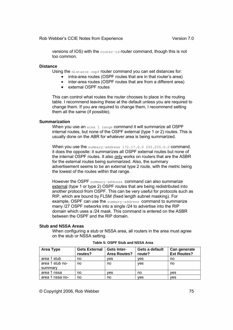
Rob Webber�s CCIE Notes from Experience Version 7.0
© Copyright 2006, Rob Webber 75
versions of IOS) with the router-id router command, though this is not too common.
DistanceUsing the distance ospf router command you can set distances for:
intra-area routes (OSPF routes that are in that router�s area) inter-area routes (OSPF routes that are from a different area) external OSPF routes
This can control what routes the router chooses to place in the routing table. I recommend leaving these at the default unless you are required to change them. If you are required to change them, I recommend setting them all the same (if possible).
SummarizationWhen you use an area 1 range command it will summarize all OSPF internal routes, but none of the OSPF external (type 1 or 2) routes. This is usually done on the ABR for whatever area is being summarized.
When you use the summary-address 172.17.0.0 255.255.0.0 command, it does the opposite: it summarizes all OSPF external routes but none of the internal OSPF routes. It also only works on routers that are the ASBR for the external routes being summarized. Also, the summary advertisement seems to be an external type 2 route, with the metric being the lowest of the routes within that range.
However the OSPF summary-address command can also summarize external (type 1 or type 2) OSPF routes that are being redistributed into another protocol from OSPF. This can be very useful for protocols such as RIP, which are bound by FLSM (fixed length subnet masking). For example, OSPF can use the summary-address command to summarize many /27 OSPF networks into a single /24 to advertise into the RIP domain which uses a /24 mask. This command is entered on the ASBR between the OSPF and the RIP domain.
Stub and NSSA Areas When configuring a stub or NSSA area, all routers in the area must agree on the stub or NSSA setting.
Table 5: OSPF Stub and NSSA Area
Area Type Gets External routes?
Gets Inter-Area Routes?
Gets a default route?
Can generate Ext Routes?
area 1 stub no yes yes no area 1 stub no-summary
no no yes no
area 1 nssa no yes no yes area 1 nssa no- no no yes yes

Rob Webber�s CCIE Notes from Experience Version 7.0
© Copyright 2006, Rob Webber 76
summary
Use a stub area (area 1 stub) to block external (type 1 and type 2) routes from being sent to the stub area. Use a stub area with no summary (area1 stub no-summary) to block all OSPF routes except those from within that area (this commands blocks inter-area routes, external type-1 routes and external type-2 routes).
Use an NSSA area when you want to block external (type 1 or type 2) routes from being sent to the area (NSSA areas do not get OSPF external routes) but you want the area to be able to originate external routes, such as from redistribution. NSSA external routes can be summarized by the router that connects between the NSSA area and the backbone.
Virtual Links You do need to have every OSPF ABR (Area Border Router) connect to area 0, either directly or through a virtual link. When setting up virtual links, the area defined (in the area 1 virtual-link 154.16.32.1command) is the area through which the virtual link will traverse. When configuring the virtual link, you must use the router id of the router at the other end of the virtual link.
If area 0 is using authentication, you must add either the authentication-key or message-digest-key to the area n virtual-link command. Additionally you must add area 0 authentication [message-digest] to all routers in area 0 including the router at the �far� end of the virtual link (even though it doesn�t really �touch� area 0 � it only connects via the virtual link).
For the following network:
R1 --- area 0 --- R2 --- area 1 --- R3 --- area 2 --- R4 --- area 3
R3 needs a virtual link to R2 and R4 needs a virtual link to R3.
Prefix Lists The way prefix lists work are you can specify a network and mask or a network and a range of masks. Specifying a network and mask is fairly simple:
ip prefix-list mylist seq 10 permit 172.16.25.0/24
This will allow (match) the exact network 172.16.25.0/24 to pass the list. Prefix lists can also specify a range of networks (very useful) using the geand le keywords. The keyword ge matches a mask that is greater than or
Rob Webber�s CCIE Notes from Experience Version 7.0
© Copyright 2006, Rob Webber 77
equal to the network specified. The keyword le matches a mask smaller than or equal to the one specified.
So ge 27 le 30 indicates masks greater than or equal to /27 and less than or equal to /30: /27, /28, /29 and /30 (255.255.255.224 through 255.255.255.252).
In this following example:
ip prefix-list mylist seq 10 permit 172.16.0.0/16 ge 24 le 26
This will take the entire class B network 172.16.0.0 (172.16.0.0/16) and pass only subnets with a /24, /25 or /26 mask (ge 24 le 26). So the exact network 172.16.0.0/16 would actually fail the list because it does not have a mask of /24, /25 or /26.
By default if you only specify �ge� then any subnet with a mask greater than or equal to the ge value will pass. That is, ge all the way up to /32. For example:
ip prefix-list mylist seq 10 permit 10.10.10.0/24 ge 28
This list specifies any subnet within the 10.10.10.0/24 range that has a mask of /28 or greater (255.255.255.240 255.255.255.255). Again, the exact subnet 10.10.10.0/24 would fail because it does not have a mask of /28 or greater.
By default if you only specify �le� then any subnet with a mask less than or equal to the le value but greater than or equal to the mask specified will pass. That is, le all the way down to the mask listed. For example:
ip prefix-list mylist seq 10 permit 10.64.0.0/16 le 23
This list specifies any subnet within the 10.64.0.0/16 range that has a mask between /16 and /23, inclusive (255.255.0.0 255.255.254.0). In this case the exact subnet 10.64.0.0/16 would pass because it has a mask in the range /16 /23.
The prefix list command:
ip prefix-list allow-in seq 10 permit 10.10.128.0/19 ge 23 le 24
would have the following effect: 10.10.128.0/23 would pass 10.10.159.0/24 would pass 10.10.140.0/23 would pass 10.10.160.0/24 would fail (not in range of 10.10.128.0/19)
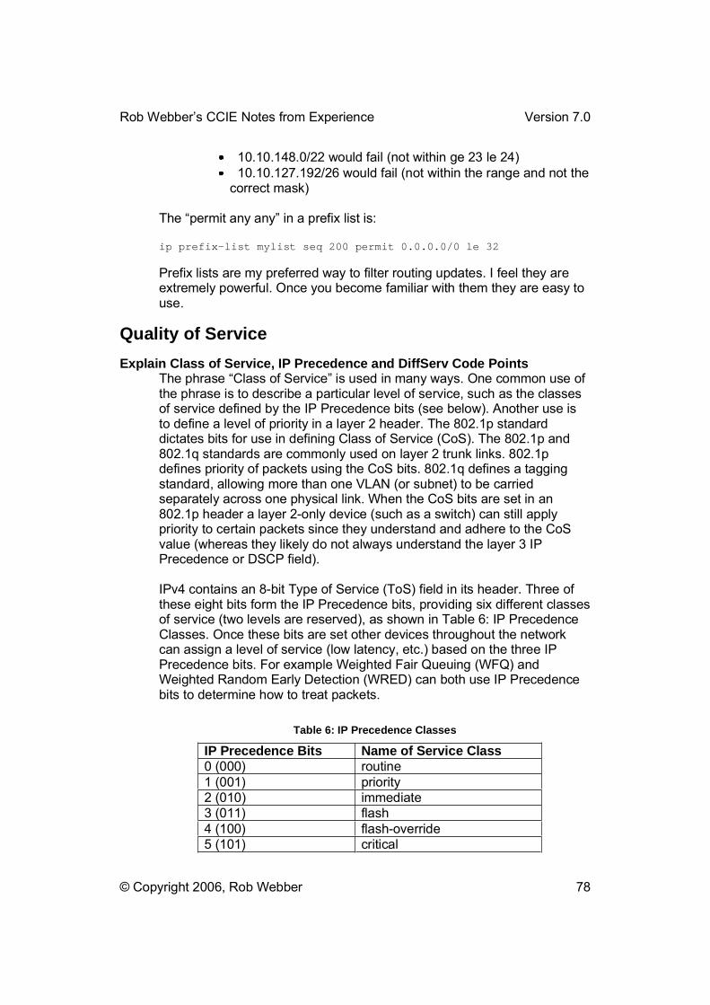
Rob Webber�s CCIE Notes from Experience Version 7.0
© Copyright 2006, Rob Webber 78
10.10.148.0/22 would fail (not within ge 23 le 24) 10.10.127.192/26 would fail (not within the range and not the correct mask)
The �permit any any� in a prefix list is:
ip prefix-list mylist seq 200 permit 0.0.0.0/0 le 32
Prefix lists are my preferred way to filter routing updates. I feel they are extremely powerful. Once you become familiar with them they are easy to use.
Quality of Service Explain Class of Service, IP Precedence and DiffServ Code Points
The phrase �Class of Service� is used in many ways. One common use of the phrase is to describe a particular level of service, such as the classes of service defined by the IP Precedence bits (see below). Another use is to define a level of priority in a layer 2 header. The 802.1p standard dictates bits for use in defining Class of Service (CoS). The 802.1p and 802.1q standards are commonly used on layer 2 trunk links. 802.1p defines priority of packets using the CoS bits. 802.1q defines a tagging standard, allowing more than one VLAN (or subnet) to be carried separately across one physical link. When the CoS bits are set in an 802.1p header a layer 2-only device (such as a switch) can still apply priority to certain packets since they understand and adhere to the CoS value (whereas they likely do not always understand the layer 3 IP Precedence or DSCP field).
IPv4 contains an 8-bit Type of Service (ToS) field in its header. Three of these eight bits form the IP Precedence bits, providing six different classes of service (two levels are reserved), as shown in Table 6: IP Precedence Classes. Once these bits are set other devices throughout the network can assign a level of service (low latency, etc.) based on the three IP Precedence bits. For example Weighted Fair Queuing (WFQ) and Weighted Random Early Detection (WRED) can both use IP Precedence bits to determine how to treat packets.
Table 6: IP Precedence Classes
IP Precedence Bits Name of Service Class 0 (000) routine 1 (001) priority 2 (010) immediate 3 (011) flash 4 (100) flash-override 5 (101) critical

Rob Webber�s CCIE Notes from Experience Version 7.0
© Copyright 2006, Rob Webber 79
6 (110) internet control (reserved) 7 (111) network control (reserved)
The DiffServ Code Point (DSCP) uses (and replaces) the Type of Service (ToS) field in the IPv4 header. The eight bits of the IPv4 Type of Service field are:
the three IP Precedence bits (discussed earlier in this section) one bit for �low delay� one bit for �high throughput� one bit for �high reliability.�
The last two bits of the ToS field are not used. DSCP uses these first six bits to define its levels of service, also known as forwarding classes.
Table 7: DSCP Classes
DSCP Value Forwarding Class Default Forwarding 000000 Assured Forwarding � Class 1 � 4 001010 through 100110 Expedited Forwarding 101110
IPv6 (for those of you who are really optimistic!) has a �Traffic Class� field that is very similar to the IPv4 Type of Service field. This field also contains bits used to prioritize traffic. DSCP also replaces this field with its own information.
Classification and Marking Classification is identifying a packet based on some criteria and assigning it to a group that can be given a particular class of service. Classification can be based on many factors, such as receiving interface, ACLs, protocol, etc.
Marking is changing or setting part of the packet, allowing it to be easily recognized throughout the network so that a class of service can be applied. Marking can be done by:
Setting the IP Precedence or DSCP bits in the IP header Setting the Class of Service (CoS) bits in the layer 2 802.1p
header Associating a local QoS group value with the packet
Setting the IP Precedence or DSCP bits is very effective since once these values are set, by default, layer 3 devices adhere to but do not alter them. These also determine how Weighted Random Early Detection (WRED) treats packets in a congestion situation.

Rob Webber�s CCIE Notes from Experience Version 7.0
© Copyright 2006, Rob Webber 80
Setting the CoS value is not as useful since it is not maintained from end-to-end throughout the network � it gets removed when the 802.1p header is stripped. However it is very useful for marking (and thus prioritizing) traffic on a trunk link, switch-to-switch link or router-to-switch link. DSCP values can also get mapped based on CoS values, making the marking more permanent.
Setting a local QoS group is useful to classify packets within a router (not between routers). This classification can be made based on parameters such as IP prefix, autonomous system and BGP community values.
Congestion Management Congestion management techniques allow you to control congestion by determining the order in which packets are sent out an interface based on priorities assigned to each packet. Congestion management includes:
Creating queues Using classification to assign packets to queues Scheduling packets in a queue for transmission
IOS provides four broad types of queuing (congestion management) techniques:
First In, First Out (FIFO) Weighted Fair Queuing (WFQ) Custom Queuing (CQ) Priority Queuing (PQ)
First In, First Out is by far the simplest queuing mechanism. Packets are sent out an interface in the order they are received. No preferential treatment is administered, no bandwidth is reserved. Although FIFO sounds almost overly simplistic, on higher speed interfaces (over T1/E1) it is the default. This is mostly because it is extremely easy for the router to process packets and the average wait or delay on these interfaces is usually very low.
Weighted Fair Queuing actually includes four different variations: Flow-Based Weighted Fair Queuing (WFQ) Class-Based Weighted Fair Queuing (CBWFQ) Distributed Weighted Fair Queuing (DWFQ) Distributed Class-Based Weighted Fair Queuing (DCBWFQ)
The first two types are designed for the standard IOS routers. The distributed types are simply the same implementations as the non-distributed types, but designed for the Route Switch Processor (7000 series) or the Versatile Interface Processor (VIP) (7500 series). In this guide unless otherwise noted WFQ will denote both WFQ and DWFQ. Similarly CBWFQ will be used to mean CBWFQ and DCBWFQ.
Rob Webber�s CCIE Notes from Experience Version 7.0
© Copyright 2006, Rob Webber 81
With WFQ the router identifies and sorts traffic into flows, or conversations. Each flow is assigned a weight, which effectively acts as that flow�s priority. The weight can be set by:
IP Precedence of the packet RSVP Traffic of the flow (lower traffic rates get higher weight) Frame Relay BECN, FECN and DE
The router cycles through all flows, servicing them in proportion to their weight. The router automatically sorts traffic based on many attributes, such as source and destination network or MAC address, protocol, source and destination port and socket numbers of the session, Frame Relay data-link connection identifier (DLCI) value, and ToS value. IP Precedence is part of the ToS value, and WFQ will adhere to this setting. It will give higher weights to flows with higher IP Precedence values.
The router identifies traffic as either low-volume flows (usually interactive traffic) or high-volume flows (usually file transfers or database operations). WFQ gives preferential treatment to low-volume traffic since this is usually the traffic users are waiting for when using their applications.
WFQ will adapt to changing network conditions, since it is constantly evaluating and sorting flows.
CBWFQ is similar to WFQ, but instead of the router automatically identifying and sorting flows, the administrator can manually configure classes of traffic based on protocols, access control lists, and input interfaces. CBWFQ allows the administrator to customize each class, such as defining the guaranteed bandwidth or maximum packet limit.
Once a queue has reached its maximum packet limit, any additional packets for that queue will be dropped. The user can decide whether the default, tail drop, will be used (packets at the end (or tail) of the queue that won�t fit in get dropped). The alternative to this is to use Weighted Random Early Detection (WRED) to drop excess packets.
Custom Queuing provides up to 16 queues for traffic (if you are using anywhere near 16 queues your configuration is more complicated than it needs to be!) Each queue is serviced in a round-robin fashion, with the router moving from one queue to the next, to the next. The administrator specifies how many bytes are sent from each queue before the router should move onto the next queue. If any queue is empty, the router immediately moves onto the next queue. The router maintains one queue for system traffic (keepalives, etc.) that is emptied before any other queue.
Rob Webber�s CCIE Notes from Experience Version 7.0
© Copyright 2006, Rob Webber 82
With CQ you do not specify a percentage of bandwidth, you specify a byte count for each queue. However this can indirectly be a percentage of bandwidth. For example, suppose you define three queues. If you specify byte counts of 2000 bytes, 1000 bytes and 1000 bytes, the queue with 2000 bytes will get 50% of the bandwidth (2000 out of every 2000+1000+1000=4000 bytes) and the other queues will get 25% each. Setting the byte count too high can result in delays for the other queues. For example, setting a byte count to 7500 bytes could result in five 1500 byte packets being sent. This could require 94 mS per packet (on a 128 Kb/s link). This could result in that queue sending 5 packets at 94 mS each � almost half a second of time just to service that queue!
Priority Queuing uses just four queues � high, medium, normal and low. This is the priority order of the four queues. The highest queue with traffic to send is always serviced first. Thus if the high priority queue has enough traffic to fill a link, the other three queues will never send a packet! The administrator uses filters to place packets into one of the four queues. Packets that do not match any list are placed in the normal queue. Packets can be classified by the following criteria:
Protocol or subprotocol type Incoming interface Packet size Fragments Access list
Packets are filtered and sorted by the router�s processor. This causes a slight delay in the handling of each packet. On low speed interfaces this small delay is usually acceptable (especially compared to the benefit PQ provides). On higher speed interfaces this delay may be unacceptable.
Each queue does have a limit on the number of packets that can be in the queue. This is especially helpful for the lower queues, as packets may build up there, waiting for transmission. In the case of long delays in the lower queues, the application is probably resending the data anyway � so the router is better off dropping the packets.
Keepalives are always placed in the high priority queues. Other important system traffic (OSPF hellos, CDP, etc.) needs to be manually configured.
Custom Queuing and Priority Queuing are statically configured � they do not adapt to changing conditions the way WFQ and CBWFQ do.
Policing and Shaping Policing and shaping are both traffic regulation techniques that typically evaluate traffic in the same way. Policing and shaping treat violations of traffic policy differently � policing tends to drop the packets, whereas
Rob Webber�s CCIE Notes from Experience Version 7.0
© Copyright 2006, Rob Webber 83
shaping tends to delay the packets by holding them in a buffer before queuing them. This slows down the flow of traffic.
Policing benefits QoS by preventing certain sources or applications from taking too much bandwidth (or more bandwidth than was agreed upon). Shaping helps QoS by slowing traffic when an interface gets congested. Slowing traffic is often more efficient than dropping it. Dropped packets usually get retransmitted (adding to the interface congestion, though possibly at a slower rate). Delaying packets prevents the retransmission problem but also tends to slow down traffic, easing congestion.
When to Apply and How to Configure Policing Mechanisms Policing is applied when a strict limit needs to be set on traffic (or on certain types of traffic) on a particular interface. Policing is configured by:
Creating a traffic class to define the type of traffic to be policed (class-map)
Creating a traffic policy to define the actions to be taken on the traffic (policy-map)
Applying the policy to an interface (service-policy)
class-map pop-email match access-group 100 !policy-map limit-email class pop-email police 128000 16000 32000 conform-action transmit exceed-
action set-qos-transmit 3 violate-action drop !interface serial 0/0 service-policy input limit-email !access-list 100 permit tcp any any eq pop3
The class-map uses an access list to define the type of traffic to be policed (use match any in the class-map or an ip any any in the access-list to police all traffic). The policy-map uses the traffic defined by the class-map and defines how the traffic will be treated (transmitted, dropped, change the QoS, precedence or DSCP value). The service-policy applies the policing policy to a given interface.
Identify the Various Types of Traffic Shaping and How to Apply Each Traffic shaping allows you to control traffic going out an interface. This can be done to match the speed of a remote connection or remote portion of the network, to adhere to a policy or to restrict certain types of traffic. Traffic shaping can be more useful than policing, since it shapes traffic by delaying it, whereas policing drops excess traffic. Dropped traffic often is simply retransmitted, creating inefficiency.
There are four types of traffic shaping:

Rob Webber�s CCIE Notes from Experience Version 7.0
© Copyright 2006, Rob Webber 84
1. Generic Traffic Shaping (GTS) 2. Class-based Traffic Shaping 3. Distributed Traffic Shaping (DTS) 4. Frame Relay Traffic Shaping (FRTS)
DTS is similar to GTS but primarily targeted at distributed architectures � such as the VIP processors used on 7500 routers, etc.
All four methods use similar methods to determine whether a packet can be forwarded or whether it must be delayed. If a packet must be delayed GTS and Class-based Shaping use a weighted fair queue to delay the traffic. DTS and FRTS use either a weighted queue, a custom queue or a priority queue to hold delayed traffic, depending on how they are configured.
GTS applies traffic shaping to an entire interface or to traffic based on access control lists (ACLs). Class-based shaping applies shaping to classes. Classes can be defined based on ACLs, input interfaces, protocols, etc. Shaping can be defined uniquely on each class.
FRTS can apply shaping to individual VC�s (PVCs or SVCs) that are assigned to a subinterface. In this case if a subinterface does not have any shaping configured, it will inherit the shaping on the main interface (if any is configured there). Any shaping configuration on the subinterface will override the shaping configured on the main interface.
GTS and DTS are applied to interfaces (or subinterfaces). FRTS can be applied on a per-DLCI basis. Class-based shaping is applied to a class (or, occasionally, on an interface).
A variable that you should be familiar with for traffic shaping is Bc. This is known as the �committed burst� (thus the Bc) of traffic a router can send. That is, this is the burst of traffic that a router transmits that the network (such as a Frame Relay network) is committed to accept and deliver. This is directly related to the Committed Information Rate (CIR) � the CIR is simply Bc divided by time. For example if the CIR is 128 Kb/s and the router�s sampling period is 1 second then Bc = 128,000 bits.
Another variable used in traffic shaping is Be. This is the �excess burst� (thus the Be) that the router can send that the network will accept but is not committed to deliver. It will mark this traffic discard eligible (set the DE bit) and will give a best effort to deliver this traffic, but may drop this traffic upon congestion.
The total amount of traffic the router can transmit in any given sampling period is the committed burst plus the excess burst (Bc plus Be).
Rob Webber�s CCIE Notes from Experience Version 7.0
© Copyright 2006, Rob Webber 85
Configure the Different Types of Traffic Shaping To configure Generic Traffic Shaping (GTS) on all traffic on an interface for 128 Kb/s (with a burst of 32 Kb/s): interface serial 0/0 traffic-shape rate 128000 32000
To configure GTS on an interface to limit the traffic caused by POP3 email to 500 Kb/s (all other (non-POP3) traffic will not be restricted at all): interface serial 1/0 traffic-shape group 105 500000 !access-list 105 permit tcp any any eq pop3 access-list 105 permit tcp any eq pop3 any
To configure Class-based Traffic Shaping:class-map 256k match any !policy-map houston class 256k shape average 256000 !interface serial 1 service-policy output houston
To configure Frame Relay Traffic Shaping create a class with the map-class command. Apply the map-class to an interface, subinterface or DLCI using the class command (or the frame-relay class command, depending on the config mode you are in).
For example, subinterfaces s1.2 and s1.3 do not have any shaping configured and inherit the main interface shaping (configured for a 384K PVC). S1.1 has shaping configured on the subinterface for a 512K PVC. S1.4 has individual shaping configured on the DLCI � for a 256K PVC:
interface Serial1 encapsulation frame-relay frame-relay class 384K_VCs frame-relay traffic-shaping !interface Serial1.1 point-to-point frame-relay class 512K_VCs frame-relay interface-dlci 101 !interface Serial1.2 point-to-point frame-relay interface-dlci 102 !interface Serial1.3 point-to-point frame-relay interface-dlci 103 !interface Serial1.4 point-to-point frame-relay interface-dlci 104

Rob Webber�s CCIE Notes from Experience Version 7.0
© Copyright 2006, Rob Webber 86
class 256K_VCs !map-class frame-relay 384K_VCs frame-relay traffic-rate 384000 384000 frame-relay adaptive-shaping becn !map-class frame-relay 512K_VCs frame-relay traffic-rate 512000 512000 frame-relay adaptive-shaping becn !map-class frame-relay 256K_VCs frame-relay traffic-rate 256000 256000 frame-relay adaptive-shaping becn !The map-classes also let you configure many other characteristics, such as custom queuing, priority queuing, weighted fair queuing, committed and excess burst sizes, etc.
Overview Here is a good overview of the QoS tools offered by Cisco IOS. I�ve included a few other, less commonly used QoS techniques for reference:
FIFO: default, no config necessary
WFQ:interface serial 0 fair-queue
CBWFQ:class-map Sarasota-traffic match access-group 101 or match input-interface serial 1 or match protocol ip !policy-map sarasota class Sarasota-traffic bandwidth 384 (in kb/s or you can specify percent bandwidth) queue-limit 20 random-detect (if using WRED rather than the default, tail drop) !interface serial 4/1 service-policy output sarasota
CQ:interface serial 1/1 custom-queue-list 1 !queue-list 1 protocol ip 1 tcp 23 (TCP port 23 to queue 1) queue-list 1 protocol ip 2 tcp 80 (TCP port 80 to queue 2) queue-list 1 protocol ip 3 list 100 (ACL 100 to queue 3) queue-list 1 queue 1 limit 20 (max 20 packets in queue 1) queue-list 1 queue 2 byte-count 1000 (byte count 1000 in queue 2)

Rob Webber�s CCIE Notes from Experience Version 7.0
© Copyright 2006, Rob Webber 87
PQ:priority-list 2 protocol ip high list 5 orpriority-list 2 interface ethernet 1/0 low orpriority-list 2 protocol ip medium udp 161 !interface serial 1/0 priority-group 2 !access-list 5 permit 192.168.1.0 0.0.0.255
LLQ:class-map voice-enabled match access-group 150 !policy-map phoenix class voice-enabled priority 128 !interface serial 1 service-policy output phoenix !access-list 150 permit udp any range 16384 32768 any access-list 150 permit udp any any range 16384 32768
IP RTP Priority:interface serial 0/1 ip rtp priority starting-port-number port-number-range bandwidth
CAR:interface serial 0/1 rate-limit input 128000 10000 20000 conform-action transmit
exceed-action drop
Marking:class-map telnet-class match access-group name telnet class-map web-class match access-group name www !policy-map salem class telnet-class set ip precedence 5 class web-class set ip dscp ef !interface serial 1/1 service-policy input salem !ip access-list extended telnet permit tcp any any eq telnet ip access-list extended www permit tcp any any eq www !

Rob Webber�s CCIE Notes from Experience Version 7.0
© Copyright 2006, Rob Webber 88
Policing: class-map ftp match access-group 101 !policy-map limit-ftp class ftp
police 256000 32000 32000 conform-action transmit exceed-action drop violate-action drop
!interface serial 0/0 service-policy input limit-ftp !access-list 101 permit tcp any any eq ftp-data
WRED:interface serial 0 random-detect
FRED:interface serial 1 random-detect random-detect flow random-detect flow count 16 random-detect flow average-depth-factor 8
Compressed IP RTP (CRTP): interface serial 0/0 ip rtp header-compression
interface serial 0/0 encapsulation frame-relay frame-relay map ip 10.10.0.1 17 broadcast rtp header-compression
Link Fragmentation and Interleaving (LFI) for Multilink PPP (MLP): interface virtual-template 1 ip unnumbered loopback 0 ppp multilink ppp multilink interleave ppp multilink fragment-delay 30 !multilink virtual-template 1
LFI for Frame Relay: interface Serial 3/0 no ip address encapsulation frame-relay frame-relay traffic-shaping !interface Serial 3/0.1 point-to-point frame-relay interface-dlci 83 ppp Virtual-Template1 class frame-pvc !interface Virtual-Template1 bandwidth 100

Rob Webber�s CCIE Notes from Experience Version 7.0
© Copyright 2006, Rob Webber 89
ip address 10.10.10.51 255.255.255.252 ppp authentication chap ppp chap hostname rtr3 ppp multilink ppp multilink fragment-delay 20 ppp multilink interleave !map-class frame-relay frame-pvc frame-relay cir 96000 frame-relay bc 1000 frame-relay be 0 no frame-relay adaptive-shaping
LFI using FRF.12: interface serial 1/1 frame-relay traffic-shaping frame-relay interface-dlci 105 class FR-fragment !map-class frame-relay FR-fragment frame-relay cir 64000 frame-relay fragment 25 frame-relay fair-queue
Generic Traffic Shaping: interface serial 0/0 traffic-shape rate 128000 32000
Frame Relay Traffic Shaping: interface Serial1 encapsulation frame-relay frame-relay class 384K_VCs frame-relay traffic-shaping !interface Serial1.1 point-to-point frame-relay class 512K_VCs frame-relay interface-dlci 101 !interface Serial1.2 point-to-point frame-relay interface-dlci 102 !interface Serial1.3 point-to-point frame-relay interface-dlci 103 !interface Serial1.4 point-to-point frame-relay interface-dlci 104 class 256K_VCs !map-class frame-relay 384K_VCs frame-relay traffic-rate 384000 384000 frame-relay adaptive-shaping becn !map-class frame-relay 512K_VCs frame-relay traffic-rate 512000 512000 frame-relay adaptive-shaping becn

Rob Webber�s CCIE Notes from Experience Version 7.0
© Copyright 2006, Rob Webber 90
!map-class frame-relay 256K_VCs frame-relay traffic-rate 256000 256000 frame-relay adaptive-shaping becn !
RedistributionRedistribution is the act of taking routes from one routing process (OSPF, EIGRP, static routes, etc.) and placing them into another routing process. By default, Cisco routers do not share routing information between routing processes. For example, you could have a single router running EIGRP on the 150.150.0.0 network and running RIP on the 160.160.0.0 network. By default routers on the 150.150.0.0 network would not be able to communicate with other routers on the 160.160.0.0 network. This is because the router running both protocols does not automatically share routing information between its routing processes � between EIGRP and RIP, in this case. (Users directly connected to that router would be able to communicate with each other because the router connected to both networks forwards packets between the 150.150.0.0 and 160.160.0.0 networks).
Given the choice, I would always prefer to specify networks as part of a routing process given the network command rather than using redistribute connected. The network command allows more precise control over which networks are given to a routing process.
The network command makes a route internal to a routing process, whereas redistribute makes a route external to a routing process (such as EIGRP or OSPF).
MetricsWhen redistributing from one protocol to another, it is recommended to specifically define the routing metric. This is because almost every routing protocol has a metric that is not compatible with any other protocol. You can do this in the redistribute command:
router rip redistribute eigrp 1 metric 4
Or this can be done with a default-metric command:
router rip redistribute eigrp 1 default-metric 4

Rob Webber�s CCIE Notes from Experience Version 7.0
© Copyright 2006, Rob Webber 91
When redistributing a protocol into EIGRP using the redistributecommand you need to explicitly configure the EIGRP metric (otherwise no routes get redistributed). You can do this by:
router eigrp 1 default-metric 1000 50 255 128 1514
or
router eigrp 1 redistribute bgp 65222 metric 1000 50 255 128 1514
Note: in EIGRP the metric values are (in order): BW (in Kbits/sec), delay, reliability, loading and MTU. You can select almost any allowed values for these � they don�t necessarily need to reflect the actual network.
When redistributing into RIP, make very sure you add the metric keyword, such as metric 3 (or the default-metric command). This is critical because RIP has such a low metric. Otherwise you may get the metric set to 16 (unreachable), depending on the metric of the routing protocol supplying the route.
Route-MapsI recommend getting in the habit of using route-maps when you redistribute routes. Route-maps can be used to set various route attributes, but the most common use I found was simply for filtering (controlling) what routes were actually redistributed. Often the CCIE Lab will specifically state what routes are to be redistributed (rather than simply all routes). A route-map can be used to meet this requirement. Even if the lab does not specifically require this, it is a good idea to use a route-map for filtering so that you know exactly what routes are being redistributed.
OSPFWhen redistributing a protocol into OSPF, I usually use the subnetskeyword. This enables all routes to be redistributed into OSPF. If you omit this keyword routes will be summarized to their �natural� classful mask when they are redistributed into OSPF (which is probably not what you want).
By default, routes redistributed into OSPF become external type 2 routes. Often this is fine, however at times you may need to make them external type 1 routes (see OSPF � External Routes, earlier). This can be overridden with the metric-type 1 keyword in the redistribute command.
When redistributing OSPF into BGP by default BGP will only accept OSPF internal (inter- and intra-area) routes � not external type 1 or type 2routes by default. To change this, use the match keyword:

Rob Webber�s CCIE Notes from Experience Version 7.0
© Copyright 2006, Rob Webber 92
router bgp 65000 redistribute ospf 1 match internal external 1 external 2
Summarization Notes When you redistribute, make sure that you don�t �violate� a requirement of summarization that the lab may require. For example, you may be summarizing OSPF routes. You may also be required to run RIP on those interfaces and redistribute RIP into OSPF. If you don�t use a route-map to control which routes get placed into OSPF, you�ll see the OSPF summary and one external OSPF route for each of the RIP interfaces (from the redistribution) � and thus you won�t really be summarizing correctly.
For example, examine the diagram in Figure 8: OSPF Summarization with RIP Redistribution:
router1
router2router3
172.16.254.0/24172.16.10.0/24
172.16.8.0/24
RIP
172.16.9.0/24
OSPF Area 1
router4
OSPF Area 0
Figure 8: OSPF Summarization with RIP Redistribution
You may be asked to summarize the following routes on router 1 into a single OSPF advertisement: 172.16.8.0/24172.16.9.0/24
So you create an area 1 range 172.16.8.0 255.255.254.0 statement on router 1. However you also need to run RIP on the 172.16.0.0 network for connectivity to router4 (thus RIP gets run on all the above interfaces). Assume you have to redistribute RIP into OSPF. When you do that, if
Rob Webber�s CCIE Notes from Experience Version 7.0
© Copyright 2006, Rob Webber 93
router3 happens to be also running RIP then both of the routes listed above go back into OSPF as external routes. Thus other OSPF routers will have the OSPF area summary, but also the specific routes as OSPF externals. To prevent this, filter (use a route-map) on the redistribution of RIP into OSPF to prevent the above three routes from being redistributed into OSPF.
RIPCisco supports RIP version 1 and version 2. There are several differences, though the most important difference is V2 includes the subnet mask of each route within the advertisement. Thus V2 is capable of handling variable length subnet masks. You should be familiar with and practice both as you may be required to use one or the other during the Lab exam.
You can set the version of RIP for the entire routing process (every interface):
router rip version 2
However you may also override this behavior on an interface-by-interface basis using the commands:
interface Ethernet 0 ip rip receive version 1 ip rip send version 1
RIP version 1 is a �classless� protocol. This does not mean its lacks elegance and grace (though many would argue that as well!), it means it does not share subnet information in routing updates. That is, because no subnet mask is provided for each route announced with RIP version 1, the receiving router must make certain assumptions that are detailed in the following section.
Sending and Receiving Updates RIP version 1 follows a specific algorithm when both sending and receiving updates. Part of this is a logical way to �assume� subnet mask information, but it is also a way to minimize loops:
When sending an update the router determines (for each network or subnet being sent) whether the subnet defined on the interface sending the update is in the same major network (traditional class A, B or C network) as the advertisement about to be sent. If it is not, the advertisement is sent as the major (class A, B or C) network (not as a subnet). If the subnet defined on the interface sending the update is in the same major network, the router compares the subnet mask of the
Rob Webber�s CCIE Notes from Experience Version 7.0
© Copyright 2006, Rob Webber 94
interface to that of the advertisement. If they are the same (i.e., both /24) the advertisement is sent. If they are different, the router drops the advertisement.
This is critical to understand when sending updates via RIPv1. For example consider a case where router 1 and router 2 are connected via a /24 subnet. Router 1 has four /26 subnets it needs to advertise to router 2. In this case if the subnet connecting the routers is in the same classful (major) network as the four /26 subnets, RIPv1 will not advertise the /26 subnets. Two ways to avoid this are to make the /24 connecting the routers a different major network than the /26�s. That way router 1 will summarize them to their natural (class) mask. Another way is to summarize the four /26�s to the same mask as the link between the routers (/24). This could be done with a static route to null0 (though its unlikely you�ll be allowed to do this on the exam).
When receiving updates the router makes the same comparison � whether the subnet defined on the interface receiving the updates is in the same major network (traditional class A, B or C network) as the advertisement that was received. If it is, the mask of the interface on which the update is received is applied to the advertisement. If it is not, the router examines its routing table. It determines whether it already knows about any other subnets of that major network. If it does not the �natural� class mask is applied and the update is accepted. If it does, the update is dropped.
This is why RIPv1 subnets must be contiguous. If router 1 and router 2 each have a /24 subnet of the 128.128.0.0 class B network, yet they are interconnected by a subnet not in the 128.128.0.0 range, each one will drop all the other router�s updates about it�s 128.128.x.0 subnets and routing will be incomplete.
Route Maps There are three primary uses for route-maps:
1. To control redistribution from one routing protocol to another 2. To use for policy routing 3. To control the way BGP updates are sent between BGP neighbors
My recommendation is to become extremely proficient with route maps. It is an incredibly powerful tool. The best way to become highly skilled with route maps is to practice using them many times.
You will typically need them during redistribution since you are usually limiting what routes get redistributed. However they can also perform a myriad of other functions: setting almost any BGP attribute, setting route tags, setting various routing parameters (metric, metric-type, etc.), filtering
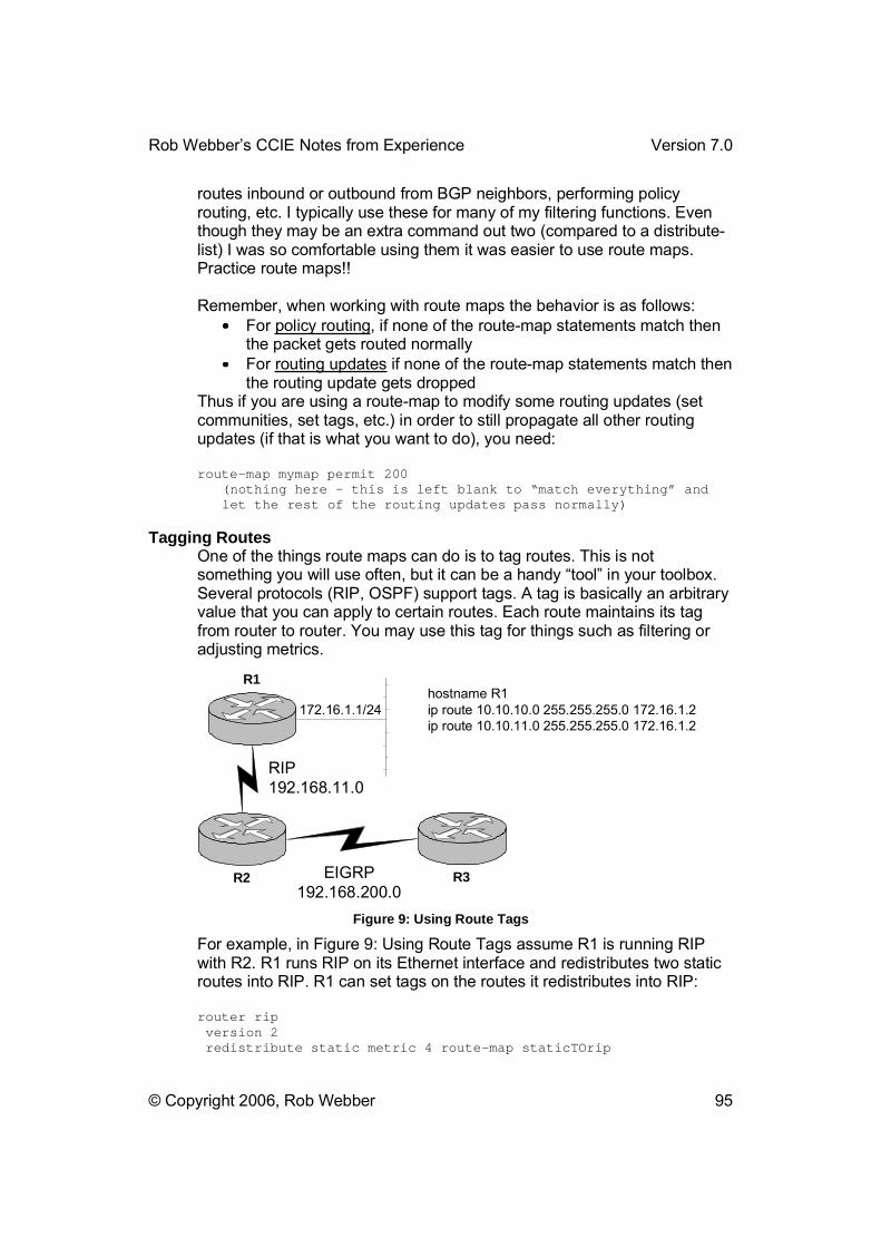
Rob Webber�s CCIE Notes from Experience Version 7.0
© Copyright 2006, Rob Webber 95
routes inbound or outbound from BGP neighbors, performing policy routing, etc. I typically use these for many of my filtering functions. Even though they may be an extra command out two (compared to a distribute-list) I was so comfortable using them it was easier to use route maps. Practice route maps!!
Remember, when working with route maps the behavior is as follows: For policy routing, if none of the route-map statements match then
the packet gets routed normally For routing updates if none of the route-map statements match then
the routing update gets dropped Thus if you are using a route-map to modify some routing updates (set communities, set tags, etc.) in order to still propagate all other routing updates (if that is what you want to do), you need:
route-map mymap permit 200 (nothing here – this is left blank to “match everything” and let the rest of the routing updates pass normally)
Tagging Routes One of the things route maps can do is to tag routes. This is not something you will use often, but it can be a handy �tool� in your toolbox. Several protocols (RIP, OSPF) support tags. A tag is basically an arbitrary value that you can apply to certain routes. Each route maintains its tag from router to router. You may use this tag for things such as filtering or adjusting metrics.
R3R2
R1
RIP192.168.11.0
EIGRP192.168.200.0
172.16.1.1/24hostname R1ip route 10.10.10.0 255.255.255.0 172.16.1.2ip route 10.10.11.0 255.255.255.0 172.16.1.2
Figure 9: Using Route Tags
For example, in Figure 9: Using Route Tags assume R1 is running RIP with R2. R1 runs RIP on its Ethernet interface and redistributes two static routes into RIP. R1 can set tags on the routes it redistributes into RIP:
router rip version 2 redistribute static metric 4 route-map staticTOrip
Rob Webber�s CCIE Notes from Experience Version 7.0
© Copyright 2006, Rob Webber 96
network 192.168.11.0 network 172.16.0.0 no auto-summary !route-map staticTOrip permit 10 match ip address prefix-list staticTOrip set tag 2222 !ip prefix-list staticTOrip seq 5 permit 10.10.10.0/24 ip prefix-list staticTOrip seq 10 permit 10.10.11.0/24
This is one way you can identify certain routes to other routers, such as R2. For example, R2 can be configured to only redistribute into EIGRP RIP routes that have tags set to 2222 (i.e., static routes on R1 that have been redistributed, not the 172.16.1.0/24 �pure RIP� network):
router eigrp 1 redistribute rip route-map ripTOeigrp network 192.168.200.0 default-metric 1000 10 255 100 1500 no auto-summary !route-map ripTOeigrp permit 10 match tag 2222
Routing (General)
Router “Network” Statements When you specify a network via the network statement in eigrp, rip, etc., that triggers the software to perform two related but slightly different tasks:
1. Run that protocol on the interfaces included within the network command (broadcast routing updates, look for neighbors, etc.)
2. To incorporate that network into the protocol�s database. This means that this route will be advertised in updates.
However connected routes also include static routes that use a next-hop interface (if you look via show ip route a static route with a next hop of an interface shows as �connected�).
Passive Interface There are times when you want a route advertised by a routing protocol, but you don�t want to actually run that protocol over the interface. For example, let�s say you have a router where Ethernet 0 has an address of 192.168.33.1/24. Let�s say the router is running RIP. There will be cases where you want to advertise the 192.168.33.0/24 network via RIP, yet you don�t want to actually run RIP on Ethernet 0. That is, in this case you don�t want to send and receive updates on this interface. In this case use the network 192.168.33.0 command in RIP to include that network in your routing, but also use passive-interface ethernet 0 command in RIP to prevent updates from being sent out Ethernet 0.

Rob Webber�s CCIE Notes from Experience Version 7.0
© Copyright 2006, Rob Webber 97
Note: For protocols such as OSPF and EIGRP the passive-interfacecommand prevents sending or receiving routing updates out an interface. This is because those protocols must first form neighbor relationships (which require sending and receiving). However for RIP this command prevents sending routing updates, but it does not prevent receiving updates. To prevent receiving updates from these protocols, use filtering (route-maps, distribute-lists, etc.) See �Distribute List In� on page 36 for an example of this.
Default Metrics All routing protocols use metrics. Few, if any, routing protocols have metrics that are compatible with the metrics of other routing protocols. Thus when one protocol is redistributed into another, there is a problem with metrics. There are two basic ways to solve this issue. One is to use the metric keyword with the redistribute command. This sets the (new) metric on all routes that are redistributed with that command. The other solution is to use a default-metric command in the routing protocol that will be accepting the redistributed routes. This command basically says �if redistributed routes do not have the metric set in the redistribute command, use this metric.�
Both solutions work well, though you need to use one or the other for proper redistribution.
Split Horizon Split Horizon prevents loops by blocking the sending of any updates on an interface where the �next hop� for that route is located out that interface. Split Horizon is set on a physical interface, but that setting also applies to any subinterfaces of that interface (such as Frame Relay subinterfaces).
Many routing protocols use split horizon. RIP and EIGRP each use it. Often split horizon is turned off on a physical Frame Relay interface. Often on a remote router you will want to turn this on.
Often split horizon is turned on on a Frame Relay point-to-point or multipoint subinterface. Often on the hub router you will want to turn this off.
It is a good practice when using a protocol that runs split-horizon (IP RIP, IP EIGRP, etc.), to manually set the split-horizon to the way you need it, regardless of the default. For RIP use the (no) ip split-horizon command. For EIGRP, use the (no) ip split-horizon eigrp 1 command.
Tips & Tricks

Rob Webber�s CCIE Notes from Experience Version 7.0
© Copyright 2006, Rob Webber 98
The lab should provide colored pens and pencils. However these are about the only thing you actually can bring into the lab with you (and even with these you should probably check in advance). It might be a good idea to bring good erasers, pens and sharpened, colored pencils. I don�t recommend bringing in stencils for your diagram (though one person did the day I took my exam). You probably won�t have that much time!
Remember that control-shift-6 control-shift-6 will not break to the terminal server but rather send a break to the actual router the terminal server is connected to. This is very handy. For example, you can set up an extended ping of 1000 pings (that are failing) so that you can troubleshoot what is happening on other routers (shows, debugs, etc.) Once you have solved or identified the issue (or given up!) go back to the router doing the pinging and type control-shift-6 control-shift-6 to break from the extended ping.
If you have a serial cross-over cable and you don�t know which end is DCE or DTE, connect each end to routers and do:
show controllers serial 0
Usually in about the second line it will tell you which end of cable it is (DCE or DTE):
Test_Router_1#show controllers serial 0 HD unit 0, idb = 0x9B38C, driver structure at 0x9F010 buffer size 1524 HD unit 0, V.35 DCE cable, clockrate 1000000
If it is the DTE end, no configuration is necessary. If it is the DCE end, use:
interface Serial0 clock rate 1000000
Practice Speed Knowing all the information required to pass the CCIE lab exam is only part of what you need. Many people could pass the CCIE if they were given more time. A critical skill you will need to pass the exam is speed. The more speed you have on certain aspects of the exam, the more time you will have to search the doc CD and think about the answer on other portions of the exam. However you know certain scenarios are likely on the exam. Repeatedly practice these tasks and time yourself. Begin each speed drill with very basic router configs. Draw the relevant configuration info (DLCI�s, IP addresses, OSPF area numbers, etc.) on a piece of paper. Then time yourself and begin configuring. Actually write down how long an exercise took to complete. Repeat the exercise over several days and see how much you can improve your time. Remember, accuracy is more important than speed, but speed is a close second!

Rob Webber�s CCIE Notes from Experience Version 7.0
© Copyright 2006, Rob Webber 99
Here are some configs on which you should practice your speed: Configure a hub-and-spoke Frame Relay network of 3 or 4 routers
with a mix of physical and subinterfaces Configure three routers for BGP using the same ASN. Configure
one router to be a route reflector for the other two routers. Configure three routers for OSPF. Use at least two OSPF areas,
change the OSPF network type on 1 network and have one OSPF area summarize a couple of routes to the other OSPF area
Configure a routing protocol such as RIP or EIGRP. Configure it to run on 2 or more interfaces of router 1, one of which connects to router 2. On router 2 configure that same protocol on the interface that connects to router 1. On router 2 also configure OSPF. On router 2 redistribute the protocol into OSPF as metric-type 1, metric of 50, include subnets and use a route-map to only allow 1 of the routes from the other protocol to go into OSPF
Run BGP between two routers using different ASN�s. Use a route-map on one to set the MED and a community on advertised routes. On the other router use a filter to only accept routes from that AS and a route-map to only accept routes where the community is set correctly.
IP Subnetting It is important that you become familiar and fluent with IP subnetting. You should have a solid understanding of subnet masks (255.255.255.192), the number of subnet bits (/26) and the number of hosts allowed (64). At the beginning of my exam I took a piece of extra paper and quickly jotted down the table shown in Table 8: IP Subnetting Summary. Creating a table like this prevents you from forgetting any information, like accidentally skipping 255.255.255.248.
Table 8: IP Subnetting Summary
Subnet Mask Number of Subnet Bits
Number of IP Addresses
255.255.255.0 /24 256 255.255.255.128 /25 128 255.255.255.192 /26 64 255.255.255.224 /27 32 255.255.255.240 /28 16 255.255.255.248 /29 8 255.255.255.252 /30 4 255.255.255.254 /31 2 255.255.255.255 /32 1 This column simply needs to be memorized
This column begins at /24 and increases
This column begins at 256 and gets cut in half with each row
Rob Webber�s CCIE Notes from Experience Version 7.0
© Copyright 2006, Rob Webber 100
by 1 each row
Using this table I can quickly get the information I need, whether that is: The correct subnet mask for an interface (such as
255.255.255.128) The correct number of subnet bits (/25) for a prefix list The correct number of hosts (128) in the event the exam requires
you to create a subnet that will support 120 hosts, for example
If necessary I also create a similar table going in the other direction. For example, the first two lines of that table would be:
Subnet Mask Number of Subnet Bits
Number of IP Addresses
255.255.254.0 /23 512 255.255.252.0 /22 1024 etc.
Access Lists For access-lists:
BGP uses TCP port 179 RIPv1 uses UDP port 520 and dest. address 255.255.255.255 RIPv2 uses UDP port 520 and dest. address 224.0.0.9 OSPF uses protocol 89 and dest. address 224.0.0.5 EIGRP uses protocol 88 and dest. address 224.0.0.10 ESP (IPSec) uses protocol 50 AH (IPSec) uses protocol 51 GRE uses protocol 47 ISAKMP uses UDP port 500
For netbios host name access lists, permit * is the �permit any.� For mac-address lists permit 0000.0000.0000 ffff.ffff.ffff is the �permit any.�
At the end of an access-list place a �deny any any log� to send rejected packets to the log. This will help determine what packets may be getting blocked that are causing other things not to work (routing protocols, tunnels, IPSec, etc.). Then do a �show log� to determine what packets are being blocked.
LoggingIn order to send all messages to the on-board logging buffer (including the blocked packets mentioned, above) make sure you have the logging buffered command in your configuration. This command allows you to specify the size of the buffer, though I�ve always found the default size to

Rob Webber�s CCIE Notes from Experience Version 7.0
© Copyright 2006, Rob Webber 101
be sufficient. Use the show log command to view the messages in the buffer.
The logging console (or no logging console) command controls whether messages are sent to the console. This is enabled (logging console) by default. In order to have messages sent to a telnet session, you need both the logging console command and the terminal monitor command.
Console and VTY Ports Once you are familiar with console and vty commands such as no login, login local, etc. you can save time in your home lab by turning off authentication on these lines. This way when you are jumping from router to router via console or telnet, you do not get prompted for a password and you automatically get placed into exec mode. The commands you will need are:
no login privilege level 15 exec-timeout 120 0
I don�t recommend setting exec-timeout 0 0 in your home lab since I found this would occasionally cause a line to hang (plus with these commands it is very fast to re-establish a console or telnet session). If you haven�t used it in 2-3 hours, having the router automatically terminate the session is probably a good idea. A sample config that will save time in your home lab:
line con 0 exec-timeout 120 0 privilege level 15 no login line vty 0 4 exec-timeout 120 0 privilege level 15 no login
Terminal Editing control-A brings you to the beginning of the line control-E brings you to the end of the line control-R repaints a line (handy if a console or debug message pops up) control-U is the same as �up arrow� (in case that isn�t working)
ToolsThis section is devoted to �tools� you might use. No, I don�t mean software packages or ISDN simulators. I�m referring to scenarios where you may be testing or troubleshooting a problem and these �tools� � mostly techniques for doing certain things � may come in handy.

Rob Webber�s CCIE Notes from Experience Version 7.0
© Copyright 2006, Rob Webber 102
router1
OSPFarea 1
router3
172.31.203.1/24
172.31.4.1/24
172.31.4.3/24
router4
OSPFarea 0
172.31.3.1/24
172.31.3.4/24
router ospf 1 network 172.31.4.0 0.0.0.255 area 1
interface Serial0 ip address 172.31.3.1 255.255.255.0 ip access-group 109 outaccess-list 109 deny ip 172.31.203.00.0.0.255 any logaccess-list 109 permit ip any any
Figure 10: Using "Tools" To Help Troubleshooting
Extended Pings from Another Interface This tool can often help debug routing problems. If there are connectivity issues, this lets you control the source address of the pings being sent. For example, in Figure 10: Using "Tools" To Help Troubleshooting router3 has no problem pinging router4�s serial interface (172.31.3.4). By default router3 uses a source address of 172.31.4.3, since that is the interface it uses to route to the 172.31.3.0/24 network. Extended pings can force router3 to use a different source address when pinging router4, such as 172.31.203.1. Here is the output from both pings:
router3#ping 172.31.3.4
Type escape sequence to abort. Sending 5, 100-byte ICMP Echos to 172.31.3.4, timeout is 2 seconds:!!!!!Success rate is 100 percent (5/5), round-trip min/avg/max = 8/13/28 ms router3#router3#pingProtocol [ip]: Target IP address: 172.31.3.4 Repeat count [5]: Datagram size [100]: Timeout in seconds [2]: Extended commands [n]: ySource address or interface: 172.31.203.1
Rob Webber�s CCIE Notes from Experience Version 7.0
© Copyright 2006, Rob Webber 103
Type of service [0]: Set DF bit in IP header? [no]: Validate reply data? [no]: Data pattern [0xABCD]: Loose, Strict, Record, Timestamp, Verbose[none]: Sweep range of sizes [n]: Type escape sequence to abort. Sending 5, 100-byte ICMP Echos to 172.31.3.4, timeout is 2 seconds:.....Success rate is 0 percent (0/5) router3#
This tells us that (most likely) router4 does not have a route to get back to the 172.31.203.0/24 network. Analyzing router3 shows that the 172.31.203.0 network was not included in any of the network statements in the router ospf 1 configuration. Adding network 172.31.203.0 0.0.0.255 area 1 allows both the ping and the extended ping to complete successfully, since now router4 can route the return pings back to the 172.31.203.0/24 network.
Extended Pings with High Repeat Count At times something is not working and in order to determine why you need to create a steady stream of packets that are seeing the problem. Let�s take a case where router3 still cannot ping 172.31.3.4 using 172.31.203.1 as the source address, however this time routing is not the problem. If you do an extended ping as in the previous section, by the time you start figuring out what the problem is the five pings will have stopped and you�ll have nothing left to troubleshoot.
In this case use an extended ping on router3 to ping 172.31.3.4 from source interface 172.31.203.1. However this time use �500� as the repeat count to keep the pings coming from router3 while you troubleshoot.
You might start with router4 and do a debug ip packet detail and notice that the pings are not being received by router4. In this case you�d probably move onto router1 to determine whether the packets where being received and sent by router1. As it turns out router1 has an ipaccess-group 109 out configured on serial0 (connecting to router4), so the packets were never making it to router4. If access-list 109 had a �log� at the end of its deny statement, you would see a message like this on router1:
router1#5d19h: %SEC-6-IPACCESSLOGDP: list 109 denied icmp 172.31.203.1 -> 172.31.3.4 (0/0), 1 packet router1#
Rob Webber�s CCIE Notes from Experience Version 7.0
© Copyright 2006, Rob Webber 104
This indicates that ACL 109 was blocking traffic from 172.31.203.1 to 172.31.3.4 (just as it was supposed to). Let�s assume you didn�t have the �log� statement on access-list 109. One alternative is to issue the command debug ip packet detail on router1. In this case router1 produces the output:
5d19h: IP: s=172.31.203.1 (Serial1), d=172.31.3.4 (Serial0), len 100, access denied
Although this does not indicate access-list 109 is the culprit, it clearly indicates the packets in question are denied. Once that has been determined it won�t take you long to figure out why.
Remember that in order to stop router3�s pings (assuming you are connecting via a terminal server), use the command ctrl-shift-6 ctrl-shift-6.
Extended Pings with Large Size Packets or Large Repeat Counts There are times when small packets will be able to traverse a link without any problem, but large packets will fail. This can occur, for example, on a WAN circuit that has timing problems. This will almost never occur in the CCIE lab (then why do I care!?!!) but it can occur in the real world.
If you are troubleshooting a connectivity problem and you are able to successfully ping the opposite end of the link, consider pinging with large packet sizes (1500 bytes). If those pings fail but small pings (used by default with the �ping� command) work fine, it could well be a timing issue with the circuit. Sometimes the timing will be slightly off, yet you need a large enough packet to accumulate enough of the timing problem to actually make the packet contain errors.
Another technique I use in the �real world� is to issue a ping with a very high repeat count. I won�t hesitate to ping a router interface 5000 times, even in a production environment. The only exception to this is if the destination is over a slow WAN link. Otherwise in a healthy network these 5000 pings should finish quickly with a 100% success rate. If you drop 10 or 20 packets, this probably indicates a problem.
One way to incorporate a high number of pings and a large number of pings is to have the router perform a ping with a range of sizes. I usually use 36 as the minimum and 1500 as the maximum. This creates several thousand pings in a range of sizes:
router1#pingProtocol [ip]: Target IP address: 172.31.3.4 Repeat count [5]: Datagram size [100]: Timeout in seconds [2]:
Rob Webber�s CCIE Notes from Experience Version 7.0
© Copyright 2006, Rob Webber 105
Extended commands [n]: y Source address or interface: Type of service [0]: Set DF bit in IP header? [no]: Validate reply data? [no]: Data pattern [0xABCD]: Loose, Strict, Record, Timestamp, Verbose[none]: Sweep range of sizes [n]: y Sweep min size [36]: Sweep max size [18024]: 1500 Sweep interval [1]: Type escape sequence to abort. Sending 7325, [36..1500]-byte ICMP Echos to 172.31.3.4, timeout is 2 seconds: !!!!!!!!!!!!!!!!!!!!!!!!!!!!!!!!!!!!!!!!!!!!!!!!!!!!!! (etc.!)
This command issues 7,325 pings: one ping for every size packet from 36 bytes to 1500 bytes (a total of 1,465 pings), repeated 5 times. If you don�t want to send 7,325 pings use a Repeat count of 1 � this will just send one ping packet of each size from 36 to 1500 bytes, a total of 1,465 pings.
DebugBecoming familiar with the debug commands is invaluable to passing � and perhaps more importantly preparing for � the CCIE. I recommend experimenting with all different types of debugs to see what happens. When you are brain-dead and tired of studying, turn on some debugs and then do things to make the router react (reset BGP neighbors, drop serial links, reboot other routers, turn off routing protocols, etc.)
Other Tools Other �tools� that may come in useful are policy routing (manually controlling the flow of packets based on rules), route maps, traceroutes (to determine the path packets are taking through the network) and tunnels (discussed below).
TunnelsYou define a tunnel by configuring a source and a destination IP address. Then assign the appropriate characteristics to the tunnel (bridging, IP addresses, IP routing, etc.)
If a router learns about its tunnel destination address over the tunnel it will try to send the GRE (or whatever tunnel mode you are using) packets over the tunnel itself... that won't work! Use a distribute list to prevent each side from advertising it's tunnel source address to the other side over the tunnel. For example, perhaps two routers have a tunnel between their loopback addresses. Let�s say they are using RIP to be able to route between the loopbacks. If OSPF is enabled on the tunnel and the loopbacks, OSPF will deliver updates (through the tunnel) about the
Rob Webber�s CCIE Notes from Experience Version 7.0
© Copyright 2006, Rob Webber 106
loopback networks. Since OSPF has a better admin distance than RIP, it will supercede the RIP learned routes.
Yet now the router is attempting to maintain the tunnel (route packets to the destination) through the tunnel � but it can�t maintain the tunnel if the �next hop� is inside the tunnel!
In this case you will usually get a console message that the tunnel interface is down due to a routing loop.
Appendix A: Tera Term Macro Here is the macro I used to collect configs and routing tables. I have added comments to the macro (beginning with !) so that you can modify it for your own use. This macro assumes you are going to be connecting through a terminal server to six other routers (connected as sessions 1-6), all of which are presently in enable mode. It also assumes you are presently at the terminal server�s console prompt. At the end I have included the macro without any comments.
To actually run the macro, within Tera Term choose Control Macro, then select the text file where you saved this (or your own) macro script.
timeout = 120 ! If 2 minutes goes by and Tera Term is still waiting for a response, ! stop waiting and go ahead and continue with the macro (some! problem has occurred). directory = "C:\My Router configs\" ! This sets the default directory for storing the collected logs.! Set this to whatever directory you will use for storing! configs. Note: also set this a few lines down as well (where! you see “directory”)inputbox "Name of log file for this test:" "check out www.Callisma.com" ! This prompts the user to enter the filename of this log.! Directory is not needed since the default directory (listed! above) will be added. I usually use “.doc” extensions on the! name (that I place in this box) so they will automatically be! opened by Word. strconcat directory inputstr ! This adds the directory onto the filename inputted by the user! (thus making a complete filename). logfilename = directory ! This sets the variable “logfilename” to be the name of the log ! file (includes directory and name). directory = "C:\My Router configs\" ! This sets the default directory back to what you want it to be! since the variable “directory” just got the actual filename! crammed on the end of it a few lines back. You need to set the! default directory here and in the second line of the macro! (above). :search_logfilefilesearch logfilename if result=0 goto openlog

Rob Webber�s CCIE Notes from Experience Version 7.0
© Copyright 2006, Rob Webber 107
inputbox "Enter new filename:" "File already exists, you idiot!" strconcat directory inputstr logfilename = directory directory = "C:\My Router configs\" goto search_logfile ! The above lines search to determine if the filename you entered ! already exists. If it does, it prompts you for a new name. The! Macro can append onto an existing file, but that is “beyond the! scope of this macro.” :openloglogopen logfilename 1 1 ! This opens the actual logfile. I don’t remember what the “1 1” ! does…I’m sure it’s in the documentation…
sendln "show clock" wait "#" ! Asks the router what time and date it thinks it is… (for! reference)
sendln "term length 0" wait "#" sendln "show running-config" pause 16 sendln "show ip route" wait "#" sendln "term length 42" wait "#" pause 1 ! This sends the commands shown above to the terminal server! router (since that is where you are connected when you begin! the macro). Term len 0 is important so the router does not wait! for you to hit the spacebar. Pause 16 (16 seconds) is handy! since it takes several seconds for the 2500’s to get the config! ready. You may want to increase this or decrease this for each ! of your routers depending on whether they are faster or slower ! (is there such a thing as slower than a 2500? :^)! In each case Tera Term is waiting for a # character to! appear (i.e., the # following the router’s prompt – you need to! be in exec mode…)Here is where you can add whatever commands! are of interest to you.
send "1" sendln #13 wait "#" ! This sends the command “1” to the terminal server, which ! instructs it to connect to session 1. This is why it’s! important to have the routers already connected in sessions 1-6! (or however many routers you have) rather than session 1,3,4,6! (which can happen if you disconnect sessions, etc.) It then! sends a <Return> to the router (which is the “sendln #13”) to! get it to display it’s prompt.
sendln "term length 0" wait "#" sendln "show running-config" pause 16 sendln "show ip route"

Rob Webber�s CCIE Notes from Experience Version 7.0
© Copyright 2006, Rob Webber 108
wait "#" sendln "term length 42" wait "#" pause 1 ! All commands are now issued to router1 (or whatever router is! session 1 on the terminal server). After we have issued the! commands, set the length of the screen to 42 (some people! prefer 24).
sendln #30#$78 wait "#" send "2" sendln #13 wait "#" ! The #30#$78 sends a “Control-Shift-6 X” so that you can jump! back to the terminal server. It then sends a 2 to connect to! session 2 (which is the next router and the process starts all ! over again).
sendln "term length 0" wait "#" sendln "show running-config" pause 16 sendln "show ip route" wait "#" sendln "term length 42" wait "#" pause 1
sendln #30#$78 wait "#" send "3" sendln #13 wait "#" ! Simply cut and paste the appropriate section based on the number of! routers (and thus terminal server sessions) you have.
sendln "term length 0" wait "#" sendln "show running-config" pause 16 sendln "show ip route" wait "#" sendln "term length 42" wait "#" pause 1
! Here are the commands for router4 (terminal session 4):
sendln #30#$78 wait "#" send "4" sendln #13 wait "#"
sendln "term length 0" wait "#"

Rob Webber�s CCIE Notes from Experience Version 7.0
© Copyright 2006, Rob Webber 109
sendln "show running-config" pause 16 sendln "show ip route" wait "#" sendln "term length 42" wait "#" pause 1
! Here are the commands for router5 (terminal session 5):
sendln #30#$78 wait "#" send "5" sendln #13 wait "#"
sendln "term length 0" wait "#" sendln "show running-config" pause 16 sendln "show ip route" wait "#" sendln "term length 42" wait "#" pause 1
! Now go back to the terminal server router for the final time:
sendln #30#$78 wait "#"
logclose
Here is the macro without any added comments. Note that I used an alias of �i� representing �show ip routes� on all my routers:
timeout = 120 directory = "C:\My Router configs\" inputbox "Name of log file for this test:" "Callisma Rules" strconcat directory inputstr logfilename = directory directory = "C:\My Router configs\" :search_logfilefilesearch logfilename if result=0 goto openlog inputbox "Enter new filename:" "File already exists!" strconcat directory inputstr logfilename = directory directory = "C:\My Router configs\" goto search_logfile :openloglogopen logfilename 1 1
sendln "show clock" wait "#"

Rob Webber�s CCIE Notes from Experience Version 7.0
© Copyright 2006, Rob Webber 110
sendln "term length 0" wait "#" sendln "show running-config" pause 16 sendln "i" wait "#" sendln "term length 42" wait "#" pause 1
send "1" sendln #13 wait "#"
sendln "term length 0" wait "#" sendln "show running-config" pause 16 sendln "i" wait "#" sendln "term length 42" wait "#" pause 1
sendln #30#$78 wait "#" send "2" sendln #13 wait "#"
sendln "term length 0" wait "#" sendln "show running-config" pause 16 sendln "i" wait "#" sendln "term length 42" wait "#" pause 1
sendln #30#$78 wait "#" send "3" sendln #13 wait "#"
sendln "term length 0" wait "#" sendln "show running-config" pause 16 sendln "i" wait "#" sendln "term length 42" wait "#" pause 1
Rob Webber�s CCIE Notes from Experience Version 7.0
© Copyright 2006, Rob Webber 111
sendln #30#$78 wait "#" send "4" sendln #13 wait "#"
sendln "term length 0" wait "#" sendln "show running-config" pause 16 sendln "i" wait "#" sendln "term length 42" wait "#" pause 1
sendln #30#$78 wait "#" send "5" sendln #13 wait "#"
sendln "term length 0" wait "#" sendln "show running-config" pause 16 sendln "i" wait "#" sendln "term length 42" wait "#" pause 1
sendln #30#$78 wait "#"
logclose

Rob Webber�s CCIE Notes from Experience Version 7.0
© Copyright 2006, Rob Webber 112
CCIE Study sheet
Essential Configurations for Cisco Routers and Switches
byRobert Webber
CCIE 6922
© Copyright 2000-2005, Robert Webber
Rob Webber�s CCIE Notes from Experience Version 7.0
© Copyright 2006, Rob Webber 113
Foreword
The CCIE test is demanding. However your mental state of mind can have a dramatic outcome on your performance. Study the material well and be confident that you will succeed. There is tremendous power in positive thinking!
At some point a few days before you take the exam (when you are relaxed) visualize passing the test. Visualize walking into the lab, seeing the rack and getting handed the test. Visualize seeing several things (core topics) on the test that you know cold. There will also be some topics you are very unfamiliar with � this is expected. Part of the CCIE testing is seeing if you can react quickly. These are usually only worth a few points and are not incredibly difficult. Don’t get psyched out by the exam!
Visualize yourself completing one task, then another, then another. Visualize completing the morning with many of the configuration tasks complete. Visualize finishing the day with an hour or so left to check your work (and please check it � there will be a few �stupid� mistakes. In fact, given the option of spending the final hour trying to get something to work that has alluded you, you�re probably better off spending it reviewing for completeness all the things you�ve finished.)
Visualize getting your CCIE number and imagine what that will feel like.
Do this entire process several times; it will help reinforce your confidence. Make up your mind that you are going to study hard, prepare well, execute beautifully and pass the test!
R.W. February 21, 2001 CCIE 6922
3550EtherchannelVTP
vtp mode server vtp domain lab vtp password cisco vtp version 2
vtp mode client vtp domain lab vtp password cisco vtp version 2
Access Lists

Rob Webber�s CCIE Notes from Experience Version 7.0
© Copyright 2006, Rob Webber 114
Standard Access Lists access-list 1 permit 10.2.50.0 0.0.0.255 access-list 1 permit 10.10.0.0 0.0.255.255
interface serial 0/1 ip access-group 1 in
line vty 0-4 access-class 1 in
Extended Access Lists access-list 100 permit ip 172.18.0.0 0.0.255.255 192.168.1.0 0.0.0.255access-list 101 permit tcp 155.182.10.0 0.0.0.255 192.233.145.0 0.0.0.255 eq 23access-list 101 permit udp 10.0.0.0 0.255.255.255 gt 1023 192.168.0.0 0.0.255.255access-list 101 permit icmp any any echo-reply
router eigrp 200 distribute-list 101 out
Named Access Lists ip access-list (standard|extended) nameoflist permit ip 208.14.35.0 0.0.0.255 any permit tcp 155.182.0.0 0.0.255.255 eq 80 any
show access-list
Reflexive Access Lists See “Firewalls”
Aliasesalias exec i show ip route
BGProuter bgp 65000 no synchronization neighbor 10.2.1.1 remote-as 65001 neighbor 10.2.1.1 distribute-list 3 in neighbor 10.10.150.2 remote-as 65000 network 10.10.10.0 mask 255.255.255.0 network 150.150.0.0 no auto-summary
access-list 3 permit 192.168.17.0 access-list 3 permit 172.16.0.0
show ip bgp show ip bgp neighbor show ip bgp summary debug ip bgp updates

Rob Webber�s CCIE Notes from Experience Version 7.0
© Copyright 2006, Rob Webber 115
Filtering with Route-Maps router bgp 65111 neighbor 10.10.10.10 remote-as 65222 neighbor 10.10.10.10 route-map OuttoR4 out !ip prefix-list OuttoR4 seq 5 permit 172.17.0.0/16 le 32 !route-map OuttoR4 permit 10 match ip address prefix-list OuttoR4
This config uses the same name for the route-map and prefix list (OuttoR4) for simplicity. It allows any route in the entire 172.17.0.0/16 class B range to be sent to BGP neighbor 10.10.10.10, but filters all others.
Filtering by AS_PATH Filtering by AS_PATH is important because you can filter all routes originating from a given AS, any routes that have been through (transited) an AS, etc. You will want to check out �Regular Expressions� later in this document (page 134). There are two basic ways to filter by AS_PATH:
1. Use the neighbor filter-list command 2. Use a route-map
In either case you will define the AS_PATH you are looking for with the ipas-path access-list command. Here is an example of the route-map method. This config sends out to neighbor 172.16.40.5 any routes that originated in AS 200 (but drops all other advertisements to that neighbor):
router bgp 65001 no synchronization neighbor 172.16.40.5 remote-as 500 neighbor 172.16.40.5 route-map AS500filter out !ip as-path access-list 150 permit _200$ !route-map AS500filter permit 10 match as-path 150
EBGP Peers between loopback addresses This configuration shows how to peer EBGP peers between loopback addresses as well as how to load balance traffic across two T1�s:
hostname r1 !interface Loopback0 ip address 206.30.0.78 255.255.255.255 !router bgp 4293 no synchronization neighbor 208.172.50.4 remote-as 3561 neighbor 208.172.50.4 ebgp-multihop 255 neighbor 208.172.50.4 update-source Loopback0
Rob Webber�s CCIE Notes from Experience Version 7.0
© Copyright 2006, Rob Webber 116
!ip route 208.172.50.4 255.255.255.255 Serial0/0 ip route 208.172.50.4 255.255.255.255 Serial0/1
hostname r2 !interface Loopback0 ip address 208.172.50.4 255.255.255.255 !router bgp 3561 no synchronization neighbor 206.30.0.78 remote-as 4293 neighbor 206.30.0.78 ebgp-multihop 255 neighbor 206.30.0.78 update-source Loopback0 !ip route 206.30.0.78 255.255.255.255 Serial0 ip route 206.30.0.78 255.255.255.255 Serial1
AS_PATH Prepending (Making the AS_PATH Longer) router bgp 65333 no synchronization network 172.17.2.0 mask 255.255.255.0 network 172.16.1.0 mask 255.255.255.0 neighbor 192.168.4.1 remote-as 65222 neighbor 192.168.4.1 route-map make-as-path-longer out !access-list 1 permit 172.16.0.0 access-list 2 permit any !route-map make-as-path-longer permit 10 match ip address 1 set as-path prepend 65333 65333 !route-map make-as-path-longer permit 20 match ip address 2
Route Map to Set Local Preference on Incoming Updates This example uses a route map to set local preference on all updates from neighbor 192.168.11.2 to 700. This will make the entire 65001 Autonomous System prefer updates received from this neighbor rather than updates on the same networks received from any other BGP neighbor (assuming no other Local Pref is set higher):
router bgp 65001 no synchronization neighbor 192.168.11.2 remote-as 65000 neighbor 192.168.11.2 route-map setLocalPref in no auto-summary !route-map setLocalPref permit 10 set local-preference 700 !
Route Map to Set MED on outgoing updates

Rob Webber�s CCIE Notes from Experience Version 7.0
© Copyright 2006, Rob Webber 117
This example sets the MED (similar to a metric) to 200 on outgoing updates for the 172.17.0.0 and 172.30.0.0 networks sent to BGP neighbor 192.168.2.1. All other updates use the default MED (0). MEDs can influence how traffic is sent into your Autonomous System:
router bgp 65333 neighbor 192.168.2.1 remote-as 65222 neighbor 192.168.2.1 route-map set-MED out !route-map set-MED permit 10 match ip address 1 set metric 200 !route-map set-MED permit 20 match ip address 2 !access-list 1 permit 172.17.0.0 access-list 1 permit 172.30.0.0 access-list 2 permit any
Route Reflector Cluster Server (64.71.100.1): router bgp 65001 no synchronization neighbor 64.71.100.4 remote-as 65001 neighbor 64.71.100.4 route-reflector-client neighbor 64.71.100.5 remote-as 65001 neighbor 64.71.100.5 route-reflector-client
A Client (64.71.100.4): router bgp 65001 no synchronization neighbor 64.71.100.1 remote-as 65001
Aggregate Address Here all four BGP networks are summarized into one aggregate and all other advertisements (the actual /24 networks) are suppressed:
interface Loopback90 ip address 172.24.1.1 255.255.255.0 !interface Loopback91 ip address 172.24.2.1 255.255.255.0 !interface Loopback92 ip address 172.24.254.1 255.255.255.0 !interface Loopback93 ip address 172.25.3.1 255.255.255.0 !router bgp 65002 no synchronization bgp log-neighbor-changes network 172.24.1.0 mask 255.255.255.0
Rob Webber�s CCIE Notes from Experience Version 7.0
© Copyright 2006, Rob Webber 118
network 172.24.2.0 mask 255.255.255.0 network 172.24.254.0 mask 255.255.255.0 network 172.25.3.0 mask 255.255.255.0 aggregate-address 172.24.0.0 255.254.0.0 summary-only neighbor 172.31.2.3 remote-as 65003 no auto-summary
Here three aggregate advertisements are generated. All other advertisements in the 192.168.1.0/24 and 192.168.2.0/24 ranges are suppressed. An aggregate of 10.8.0.0/13 will be advertised. Any other advertisements in this range will be advertised normally.
router bgp 65222 no synchronization network 192.168.1.64.0 mask 255.255.255.192 network 192.168.1.128.0 mask 255.255.255.224 network 192.168.2.192.0 mask 255.255.255.240 network 10.8.32.0 mask 255.255.255.0 network 10.9.0.0 mask 255.255.0.0 network 10.10.160.0 mask 255.255.254.0 aggregate-address 10.8.0.0 255.248.0.0 aggregate-address 192.168.1.0 255.255.255.0 summary-only aggregate-address 192.168.2.0 255.255.255.0 summary-only no auto-summary
Bridging
Globalbridge 1 protocol ieee bridge 1 priority 100
Interface interface e0 bridge-group 1 bridge-group 1 path-cost 50
interface serial 1 bridge-group 1
show bridge
CET – Cisco Encryption Technology
The basic steps for configuring CET are 1. Generate DSS public/private keys 2. Exchange DSS public/private keys between routers 3. Enable DES encryption algorithms 4. Define crypto maps and apply them to an interface
crypto key generate dss Router1 (often the name of the router) show crypto key mypubkey dss (view public keys) copy system:running-config nvram:startup-config (save private keys)
Rob Webber�s CCIE Notes from Experience Version 7.0
© Copyright 2006, Rob Webber 119
Configure one router to be �active� in key exchange, the other to be �passive�:
crypto key exchange dss passive (on one router) crypto key exchange dss ip_address_of_passive Router1 (key name)
crypto cisco algorithm des
access-list 100 permit ip 10.1.1.0 0.0.0.255 192.168.15.0 0.0.0.255
crypto map mymap 10 cisco set peer Router2 (key name received from other router) match address 100 set algorithm des
interface serial 0 crypto map mymap
If a router has more than one CET peer, simply add more sequences to the crypto map, one for each remote peer.
DHCPOften � both when studying for the CCIE exam and even in real life (imagine that � something that is useful in both cases!), I find it useful to make the router a DHCP server. For example my laptop is configured for DHCP (for work, etc.), yet when I take my laptop home I do not have a DHCP server to assign me an address. To configure your router as a DHCP server, use the following:
! Addresses .1 - .10 are usually used for network devices, so ! we will exclude them from DHCP: !ip dhcp excluded-address 172.16.64.1 172.16.64.10 !! This creates 10 minute leases. You’ll probably want to make the! lease time much longer: !ip dhcp pool mypool network 172.16.64.0 255.255.255.0 default-router 172.16.64.1 domain-name callisma.com dns-server 199.45.32.37 lease 0 0 10
If you need to assign your PC the exact same address every time, you can create a specific reservation within DHCP based on your MAC address. That configuration is:
! The "client-identifier" is the MAC address. The pool name can ! be anything – I gave it my name to remind me its my MAC! address. Here I will always receive address 10.5.22.10. !ip dhcp pool robwebber

Rob Webber�s CCIE Notes from Experience Version 7.0
© Copyright 2006, Rob Webber 120
host 10.5.22.10 255.255.255.0 client-identifier 0100.10a4.b5d1.d0 default-router 10.5.22.250 dns-server 155.108.39.200 domain-name state.com lease 0 6
Note that only certain versions of IOS support the DHCP functionality. In most versions of 12.1 you will need the �T� technology train version of IOS.
EIGRPinterface serial0 ip summary-address eigrp 1 176.14.0.0 255.255.0.0 no ip split-horizon eigrp 1 router eigrp 1 no auto-summary network 24.0.0.0 network 176.14.0.0 network 200.1.155.0 distribute-list 107 in serial0
debug ip routing
Firewalls
Context Based Access Control (CBAC) ip inspect name myfirewall tcp
interface Ethernet 0 (inside interface) ip inspect myfirewall in
interface serial 0 (outside interface) ip access-group 100 in
access-list 100 deny ip any any
Reflexive Access Lists interface Serial 1 description Access to the Internet via this interface ip access-group inboundfilters in ip access-group outboundfilters out !ip reflexive-list timeout 120 !ip access-list extended outboundfilters permit tcp any any reflect tcptraffic !ip access-list extended inboundfilters permit bgp any any permit eigrp any any deny icmp any any evaluate tcptraffic
Rob Webber�s CCIE Notes from Experience Version 7.0
© Copyright 2006, Rob Webber 121
Lock and Key Access interface serial 0 ip address 172.17.1.1 255.255.255.0 ip access-group 101 in !access-list 101 permit tcp any host 172.17.1.1 eq telnet access-list 101 dynamic dunno permit ip any any !line vty 0 4 password mypassword login autocommand access-enable
This works, however everyone who telnets to the router activates the autocommand and gets disconnected � not very useful! A better way is:
username bob password 0 cisco username bob autocommand access-enable username sue password 0 mypass interface serial 0 ip address 172.17.1.1 255.255.255.0 ip access-group 101 in !access-list 101 permit tcp any host 172.17.1.1 eq telnet access-list 101 dynamic dunno permit ip any any !line vty 0 4 password mypassword login local
Frame Relay
Frame Relay Switching frame-relay switching interface s0 encapsulation frame-relay frame-relay intf-type dce (nni if connecting to another frame switch) frame-relay route 100 interface s1 150 (in-dlci out-interface out-dlci) clock rate 512000 (if using a DCE cable)
Frame Relay Interface s0 Ip address 172.24.1.1. 255.255.255.0 encapsulation frame-relay frame-relay map ip 172.24.1.2 330 broadcast frame-relay map ip 172.24.1.3 340 broadcast
Or�
interface s0 no ip address
Rob Webber�s CCIE Notes from Experience Version 7.0
© Copyright 2006, Rob Webber 122
encapsulation frame-relay
interface s0.1 point-to-point ip address 172.24.1.1 255.255.255.0 frame-relay interface-dlci 330
interface s0.2 point-to-point ip address 172.24.2.1 255.255.255.0 frame-relay interface-dlci 340
Or�
interface s0 no ip address encapsulation frame-relay
interface s0.1 multipoint ip address 192.168.1.1 255.255.255.0 frame-relay map ip 192.168.1.2 101 broadcast frame-relay map ip 192.168.1.3 102 broadcast
debug frame packet show frame pvc show frame map
Frame Relay Traffic Shaping interface s0 frame-relay traffic-shaping frame-relay class example1 (<- for all DLCI’s) frame-relay interface-dlci 101 class example1 (<- on a per-DLCI basis) !
map-class frame-relay example1 frame-relay priority-group 7 (<- priority queuing, or
frame-relay custom-queue-list 3 <- custom queuing) frame-relay cir 128000 frame-relay bc 256000 frame-relay adaptive-shaping becn !priority-list 7 protocol ip high priority-list 7 protocol ipx normal
!queue-list 3 protocol ip 11 queue-list 3 protocol ipx 12 queue-list 3 protocol ip 10 tcp telnet queue-list 3 default 13 queue-list 3 queue 10 byte-count 3000 queue-list 3 queue 11 byte-count 2000 queue-list 3 queue 12 byte-count 1000 queue-list 3 queue 13 byte-count 1000
HSRP

Rob Webber�s CCIE Notes from Experience Version 7.0
© Copyright 2006, Rob Webber 123
This creates two HSRP groups. Router A is primary for group 1; Router B is primary for group 2. Both primary routers are tracking their serial 0 interfaces. Should either router�s serial 0 fail, it will drop to priority 95. The other router will have (the default) priority of 100 and thus will become primary for that group as well. Group 1 also uses authentication.
Router A: standby 1 ip 172.24.1.1 standby 1 priority 105 standby 1 preempt (good idea to use this!) standby 1 authentication cisco standby 1 track serial 0 standby 2 ip 172.24.1.2 standby 2 preempt
Router B: standby 1 ip 172.24.1.1 standby 1 preempt (good idea to use this!) standby 1 authentication cisco standby 2 ip 172.24.1.2 standby 2 priority 105 standby 2 preempt standby 2 track serial 0
show standby
ISAKMP
Note: ISAKMP uses UDP port number 500 (ACLs).
For any ISAKMP (using pre-shared keys or RSA encrypted nonces):crypto isakmp policy 1 encryption des hash md5 authentication {rsa-encr|pre-share} group 1 (sets the Diffe-Hellman group) lifetime 3600
For ISAKMP using RSA encrypted nonces:crypto key generate rsa
show crypto key mypubkey rsa (to show your public key which was just generated by the previous command) crypto key pubkey-chain rsa addressed-key ip_address_of_remote_peer
key-string public_key_identified_at_peer_with_”show crypto key mypubkey rsa” command
Repeat the last few commands at each peer.
For ISAKMP using pre-shared keys:crypto isakmp key keystring address address_of_remote_peer

Rob Webber�s CCIE Notes from Experience Version 7.0
© Copyright 2006, Rob Webber 124
Repeat these steps at each peer with the identical key.
IPSEC
Note: The IPSec ESP and AH protocols use IP protocol numbers 50 and 51 (ACLs).
Manual IPSec security associations: crypto ipsec transform-set myset esp-des!crypto map mymap local-address Loopback1 crypto map mymap 10 ipsec-manual set peer 10.8.1.1 set session-key inbound esp 1000 cipher 1234567812345678 set session-key outbound esp 1000 cipher 1234567812345678 set transform-set myset match address 100 interface serial 0 crypto map mymap !access-list 100 permit ip 10.1.2.0 0.0.0.255 10.8.1.0 0.0.0.255
ISAKMP negotiated IPSec security associations: (configure ISAKMP, then…) crypto ipsec transform-set myset esp-des esp-sha crypto isakmp key mypassword address 10.8.1.1crypto map mymap 10 ipsec-isakmp match address 100 set peer 10.8.1.1 set transform-set myset interface Ethernet 0 crypto map mymap !access-list 100 permit ip 192.168.1.0 0.0.0.255 172.16.0.0 0.0.255.255
If a router has more than one IPSec peer, simply add more sequences to the crypto map, one for each remote peer.
show crypto isakmp sa show crypto isakmp policy debug crypto isakmp show crypto map show crypto ipsec sa debug crypto ipsec
Local Area Mobility interface Ethernet 0 ip address 172.16.17.1 255.255.255.0 ip mobile arp timers 120 600 access-group 2 router eigrp 1

Rob Webber�s CCIE Notes from Experience Version 7.0
© Copyright 2006, Rob Webber 125
network 172.16.0.0 redistribute mobile default-metric 80 70 60 70 100 access-list 2 deny 172.16.5.0 0.0.0.255 access-list 2 deny 172.16.12.16 0.0.0.0 access-list 2 permit 172.16.0.0 0.0.255.255
MulticastIGMP
Router(config)#interface Ethernet 0 Router(config-if)#ip igmp join-group 224.1.2.3
Console(config)#set igmp enable Console(config)#set multicast router 3/5 (required for IGMP)
CGMPRouter(config)#interface Ethernet 0 Router(config-if)#ip cgmp
Console(config)#set cgmp enable
PIM – Dense Mode ip multicast-routing !interface serial 0 ip pim dense-mode !interface ethernet 0 ip pim dense-mode ip igmp join-group 225.1.1.1 (place this on to test – should be pingable)
PIM – Sparse Mode (Static Rendezvous Point) ip multicast-routing ip pim rp-address address of rendevous router !interface serial 0 ip pim sparse-mode interface ethernet 0 ip pim sparse-mode ip igmp join-group 225.1.1.1 (place this on to test – should be pingable)
PIM – Sparse-Dense Mode (Automatic Rendezvous Point) ip multicast-routing ip pim send-rp-discovery scope 255 (only required on the RP) ip pim send-rp-announce ethernet 0 scope 255 (only required on the RP) !interface serial 0 ip pim sparse-dense-mode interface ethernet 0 ip pim sparse-dense-mode
Rob Webber�s CCIE Notes from Experience Version 7.0
© Copyright 2006, Rob Webber 126
ip igmp join-group 225.1.1.1 (place this on to test – should be pingable)
show ip mroute show ip pim neighbor show ip pim interface show ip pim rp show ip igmp groups debug ip pim
Network Address Translation (NAT)
Outgoing – Source Addresses Static:
ip nat inside source static 10.15.20.1 204.193.24.5 !interface ethernet0 ip nat inside !interface serial0 ip nat outside
Dynamic:
ip nat pool mypool 207.242.100.1 207.242.100.50 netmask 255.255.255.0ip nat inside source list 1 pool mypool overload!interface ethernet0 ip nat inside !interface serial0 ip nat outside !access-list 1 permit 192.168.2.0 0.0.0.255
Incoming – Source Addresses Static:
ip nat pool net-10 10.0.1.0 10.0.1.255 prefix-length 24 ip nat outside source list 1 pool net-10 !interface ethernet 0 ip address 171.69.232.182 255.255.255.240 ip nat outside !interface ethernet 1 ip address 9.114.11.39 255.255.255.0 ip nat inside !
Rob Webber�s CCIE Notes from Experience Version 7.0
© Copyright 2006, Rob Webber 127
access-list 1 permit 9.114.11.0 0.0.0.255
(On inbound packets with a source address of 9.114.11.0/24, the sourceaddress is translated to the 10.0.1.0/24 range. This would be useful if the 9.114.11.0/24 range was �illegally� used within your network. In that case you would need to change the source address to be able to correctly route the packets back � rather than routing them to the duplicate 9.114.11.0 subnet within your own network.)
ip nat outside source list (or static)
translates the source of the IP packets that are traveling outside to insidetranslates the destination of the IP packets that are traveling inside to outside
ip nat inside source list (or static)
translates the source of IP packets that are traveling inside to outsidetranslates the destination of the IP packets that are traveling outside to inside
show ip nat translations show ip nat statistics clear ip nat translation *
NTPClock and date commands
r1(config)# clock timezone EST -5 r1(config)# clock summer-time EDT recurring r1(config)# ntp update-calendar (if the machine has a permanent calendar)
r2# calendar set 10:05:00 4 April 2000 (if the machine has a permanent calendar) r2(config)# clock calendar-valid (if the machine has a permanent calendar)r2# clock set 10:05:00 4 April 2001 (only if the machine doesn�t have a permanent calendar)
Using one Device as an NTP Server Server:interface loopback 0 ip address 192.168.254.1 255.255.255.0 ntp master 5
Client:ntp server 192.168.254.1
Rob Webber�s CCIE Notes from Experience Version 7.0
© Copyright 2006, Rob Webber 128
Restricting Access to an NTP Server Server:interface loopback 0 ip address 192.168.254.1 255.255.255.0 ntp master 5 access-list 1 permit 172.16.24.1 ntp access-group serve 1
Client:interface loopback 0 ip address 172.16.24.1 255.255.255.0 ntp source Loopback0 ntp server 192.168.254.1
Configuring NTP Authentication Server:
ntp authenticate ntp authentication-key 1 md5 iguana ntp trusted-key 1
Clients:ntp authenticate ntp authentication-key 1 md5 iguana ntp trusted-key 1
ntp server 192.168.38.8 key 1
show clock show ntp association show ntp status
OSPFBasic
interface serial 0 ip ospf network point-to-multipoint ip ospf priority 10 ip ospf cost 150 router ospf 100 network 10.12.140.128 0.0.0.127 area 0 network 150.150.0.0 0.0.255.255 area 1 network 192.168.88.0 0.0.0.255 area 2
show ip ospf show ip ospf neighbor show ip ospf interface debug ip ospf adjacencies debug ip routing
Summarizationrouter ospf 5 network 10.4.0.0 0.0.0.255 area 0 network 10.10.140.128 0.0.0.127 area 4
Rob Webber�s CCIE Notes from Experience Version 7.0
© Copyright 2006, Rob Webber 129
area 4 range 10.10.0.0 255.255.0.0 summary-address 172.16.8.0 255.255.254.0 !router rip network 172.16.0.0
show ip ospf summary-address
Authentication – Simple (Cleartext) router ospf 1 area 0 authentication network 192.168.1.0 0.0.0.255 area 0 !interface ethernet 0 ip address 192.168.1.1 255.255.255.0 ip ospf authentication-key password
Authentication – MD5 router ospf 1 area 2 authentication message-digest network 192.168.1.0 0.0.0.255 area 2 !interface ethernet 0 ip address 192.168.1.1 255.255.255.0 ip ospf message-digest-key 1 md5 password
Note: passwords do not need to be the same for an entire area. They only need to be the same for a network (subnet) � that is, between neighboring routers. Obviously, keeping the password the same throughout an area is advisable whenever possible. Also, the command ip ospf authentication can be used to override (on an interface basis) the authentication set for an area, though this is extremely rare.
Statically Defined Neighbors If you can�t use broadcasts (as with the frame-relay map statements or if you must use ip ospf network point-to-multipoint non-broadcast, for example) you must manually define OSPF neighbors with the neighbor statement (usually done at the hub):
interface Serial0 ip address 10.0.1.1 255.255.255.0 encapsulation frame-relay frame-relay local-dlci 200 frame-relay map ip 10.0.1.3 202 frame-relay map ip 10.0.1.4 203 frame-relay map ip 10.0.1.5 204 !router ospf 1 network 10.0.1.0 0.0.0.255 area 0 neighbor 10.0.1.3 cost 5 neighbor 10.0.1.4 cost 10 neighbor 10.0.1.5 cost 15

Rob Webber�s CCIE Notes from Experience Version 7.0
© Copyright 2006, Rob Webber 130
The following is the configuration for the router on the other side:
interface Serial9/2 ip address 10.0.1.3 255.255.255.0 encapsulation frame-relay frame-relay local-dlci 301 frame-relay map ip 10.0.1.1 300 !router ospf 1 network 10.0.1.0 0.0.0.255 area 0
Stub and NSSA Areas router ospf 1 area 1 stub area 2 stub no-summary area 3 nssa area 4 nssa no-summary network 10.5.4.0 0.0.0.255 area 0 network 10.5.6.0 0.0.0.255 area 1 network 10.5.8.0 0.0.0.255 area 2 network 10.5.10.0 0.0.0.255 area 3 network 10.5.12.0 0.0.0.255 area 4
Virtual Link interface Loopback0 ip address 10.12.12.1 255.255.255.0 !interface Serial1 ip address 192.168.2.1 255.255.255.0 !router ospf 101 network 10.12.12.0 0.0.0.255 area 0 network 192.168.2.0 0.0.0.255 area 1 area 1 virtual-link 172.17.101.1
interface Loopback0 ip address 172.17.101.1 255.255.255.0 !interface Serial1 ip address 192.168.2.2 255.255.255.0 !router ospf 103 network 172.17.101.0 0.0.0.255 area 1 network 192.168.2.0 0.0.0.255 area 1 network 192.168.70.0 0.0.0.255 area 2 area 1 virtual-link 10.12.12.1
show ip ospf virtual-link
Password Recovery

Rob Webber�s CCIE Notes from Experience Version 7.0
© Copyright 2006, Rob Webber 131
Although you won�t (hopefully!) need this on the exam, I have included this section in the event you buy a used router and do not know the password.
2500/4000Reboot router. Type BREAK (control-shift-6 b on Cisco terminal server, control-F6-break on Hyperterm, Alt-b on TeraTerm). Type o/r 0x2142 at the �>� prompt (to boot from flash). Type I at the �>� prompt to reboot the router. Answer no to all set-up questions. Type enable at the Router> prompt. Type copy start run (brings in old config) Watch this!! Not the other way around!!Type config term, then either enable secret <password>. or enablepassword <password>.Type config term, then config-register 0x2102.Verify the config now in running-config is correct. Type copy run start. (Type reload. � optional)
2600/3600/4500 Reboot router. Type BREAK (control-shift-6 b on Cisco terminal server, control-F6-break on Hyperterm). Type confreg 0x2142 at the "ROMMON>" prompt (to boot from flash). Type reset at the "ROMMON>" prompt to reboot the router. Answer no to all set-up questions. Type enable at the Router> prompt. Type copy start run (brings in old config) Watch this!! Not the other way around!!Type config term, then either enable secret <password>. or enablepassword <password>.Type config term, then config-register 0x2102.Verify the config now in running-config is correct. Type copy run start. (Type reload. � optional)
Catalyst 1200 and 5000
To recover a lost password on Catalyst 1200, Catalyst 5000, and all concentrators:
1. You must be on the console. 2. Reboot the device. 3. When you see the password prompt, press Enter (null password for 30
seconds).4. Type Enable.
Rob Webber�s CCIE Notes from Experience Version 7.0
© Copyright 2006, Rob Webber 132
5. When you see the password prompt press Enter (null password for 30 seconds).
6. Change the password:
Console> (enable) set pass[Enter]Enter old password:[Enter] Enter new password:a[Enter]Retype new password:a[Enter]Password changed. Console> (enable) set enablep[Enter]Enter old password:[Enter] Enter new password:a[Enter]Retype new password:a[Enter]Password changed. Console> (enable)
Queuing and Traffic Shaping
There are as many Cisco variations of queuing as there are flavors of ice cream. However here are a few powerful ones that can satisfy many requirements:
Priority Queuing Bruce Caslow describes priority queuing as a �facist� queuing strategy since it is very strict in its approach. Higher queues get priority, period. Given enough high priority traffic, other queues can go for days without tranmitting.
priority-list 1 protocol dlsw high priority-list 1 protocol ip high tcp 23 priority-list 1 protocol ipx medium list 900 access-list 900 permit ncp any 451 any 451
interface serial 0 priority-group 1
Custom Queuing Custom queuing is fairer since it can allocate percentages of bandwidth to given queues. Typically this is done by assigning byte counts to queues. The default byte count for each queue is 1500 bytes. Thus to give a queue more bandwidth than other queues, assign it more than1500 bytes. There can be up to 16 queues, but only as many as are configured will be active.
queue-list 9 protocol dlsw 1 queue-list 9 protocol ip 1 tcp 23 queue-list 9 protocol ipx 2 list 900 queue-list 9 queue 1 byte-count 3000 queue-list 9 default 4 access-list 900 permit ncp any 451 any 451
Rob Webber�s CCIE Notes from Experience Version 7.0
© Copyright 2006, Rob Webber 133
interface serial 1 custom-queue-list 9
show queue serial 0
Frame Relay interface serial 0.0 ip addr 172.16.1.1 255.255.255.0 encapsulation frame-relay frame-relay traffic-shaping frame-relay interface-dlci 102 class myclass
map-class frame-relay myclass frame-relay cir 56000 (defines CIR) frame-relay bc 8000 (defines burst amount in bits) frame-relay be 16000 (defines excess burst in bits) fragment 160 (defines packets > 160 be fragmented) no frame-relay adaptive-shaping
RedistributionBasic
router ospf 1 redistribute rip metric 100 metric-type 1 route-map rob subnets
router eigrp 1 redistribute bgp 65000 metric 1000 10 100 100 1500
Using Route-Maps to Control Redistribution The following configuration only allows routes within the 172.16.0.0 network to be redistributed from RIP into BGP:
router bgp 65000 redistribute rip metric 6 route-map 172-16-only neighbor 192.168.11.1 remote-as 65001 !ip prefix-list 172-16-only seq 5 permit 172.16.0.0/16 le 32 !route-map 172-16-only permit 10 match ip address prefix-list 172-16-only
OSPF Example This example shows redistributing all routes from BGP 65001 into OSPF 1. Routes are set as OSPF external type-1 routes with an initial metric of 10:
router ospf 1 redistribute bgp 65001 metric 10 metric-type 1 subnets network 192.168.200.0 0.0.0.255 area 0

Rob Webber�s CCIE Notes from Experience Version 7.0
© Copyright 2006, Rob Webber 134
This example shows redistributing static routes into OSPF 1. A route-map is configured that only allows two static routes to be redistributed. One is redistributed as a metric-type 1, the other as a metric-type 2:
router ospf 1 redistribute static metric 10 subnets route-map staticTOospf network 192.168.50.0 0.0.0.255 area 0 !ip route 10.179.0.0 255.255.0.0 10.200.1.2 ip route 10.180.0.0 255.255.0.0 10.200.1.2 !ip prefix-list 10-179-0-0 seq 5 permit 10.179.0.0/16 ip prefix-list 10-180-0-0 seq 5 permit 10.180.0.0/16 !route-map staticTOospf permit 20 match ip address prefix-list 10-179-0-0 set metric-type type-1 !route-map staticTOospf permit 30 match ip address prefix-list 10-180-0-0 set metric-type type-2 !
BGP Example This example shows redistributing all routes from IGRP 1 into BGP 65001. Routes are set with a BGP community value of 11111:22222:
router bgp 65001 no synchronization redistribute igrp 1 route-map setcommunity neighbor 192.168.11.2 remote-as 65000 neighbor 192.168.11.2 send-community no auto-summary !ip bgp-community new-format !route-map setcommunity permit 10 set community 11111:22222
This example shows redistributing OSPF routes into BGP. By default only internal OSPF routes are redistributed into BGP. The match keyword changes this behavior. By specifying "match external 1" only external type 1 OSPF routes are redistributed into BGP (even internal OSPF routes are not redistributed):
router bgp 65000 no synchronization redistribute ospf 1 match external 1 neighbor 192.168.11.1 remote-as 65001 no auto-summary !
Regular Expressions
Rob Webber�s CCIE Notes from Experience Version 7.0
© Copyright 2006, Rob Webber 135
^ Denotes the start of the AS path $ Denotes the end of the AS path _ Will match a white space in the AS path (space between ASNs) . Will match any single character (dot) .* Will match any number of characters (dot, asterisk)
RIPinterface Ethernet 0 neighbor 10.150.150.1
ip rip send version 1 ip rip receive version 1!
router rip version 2 no auto-summary ! only applies if version 2 is used network 10.0.0.0 network 131.15.0.0 network 207.244.11.0 distribute-list 105 in ethernet0
default-metric 5 offset-list 10 in 4
!access-list 10 permit 10.1.99.0 0.0.0.255
In this example a neighbor is manually defined. This will cause unicast packets to be sent to that neighbor. This can be useful for media such as Frame Relay that do not always support broadcasts. This command also applies to IGRP.
The default-metric commands sets the RIP metric (hop count) for all routes redistributed into RIP.
The offset-list increases the metric (from what was learned) by 4 for all routes that match access-list 10. This command also applies to IGRP and EIGRP.
The ip rip send version and ip rip receive version override (on an interface basis) the version of RIP defined by the version router command.
debug ip rip debug ip routing
Route Maps
Rob Webber�s CCIE Notes from Experience Version 7.0
© Copyright 2006, Rob Webber 136
Note: route-map examples for redistribution are included in the �Redistribution� section (above). Route-map examples for BGP neighbors are included in the �BGP� section.
Policy Route Maps interface e2/0 ip policy route-map example
route-map example permit 10 match ip address 102 set ip next-hop 172.20.1.1
access-list 102 permit ip host 172.18.56.1 192.168.1.0 0.0.0.255
To enable the router to policy route for locally generated traffic (pings, etc.):
ip local policy route-map mymap
Switches
Catalyst 5000
set interface sc0 up set interface sc0 2 192.168.1.1 255.255.255.0 (indicates vlan 2,
specifying the vlan is optional, but recommended)
set password password for the console, vty, etc. set enablepass enablepass for enable mode
set port speed 2/6 100 set port name 3/17 To_r1 set port duplex 2/24 half
set vtp domain robsdomainset vlan 3 name First_Ethernet set vlan 4 2/1 set vlan 5 3/3-6
set ip permit enable (only affects telnet and SNMP) set ip permit 10.128.0.0 255.255.0.0 telnet
set ip route default 172.16.1.1 set ip route 172.18.0.0/20 172.16.1.2
set logout minutesset logging session (log to vty; log to console on by default)
show cam show port 4/15 show port status show vlan show vlan 2

Rob Webber�s CCIE Notes from Experience Version 7.0
© Copyright 2006, Rob Webber 137
show port show vlan all
Terminal Server Configuration interface loopback 0 ip address 10.1.1.1 255.255.255.0
ip host r1 2001 10.1.1.1 ip host r2 2002 10.1.1.1 ip host switch 2003 10.1.1.1
line 1 8 no exec transport input all
Important notes: Type control-shift-6 x to send an escape sequence to the term server
that will bring you back to the terminal server prompt. Type control-shift-6 b to send a break to a router that is being
accessed via the terminal server (handy for password recovery). To send an escape sequence to a router that is being accessed via the
terminal server, type control-shift-6 control-shift-6. This prevents you from getting tossed all the way back to the term server. Very handy for interrupting pings or traceroutes that are not completing.
You may even have to type control-shift-6 four times. For example, if you are using a term server to access a router, then that router is telnetted into another router. This requires control-shift-6 four times to escape.
TrunkingISL:
On the Catalyst 5000:
Console> (enable) set trunk 1/1 on isl
To prevent vlan 50 from using the trunk:
Console> (enable) clear trunk 1/1 50
On the Cisco 3600/4000/4500:
interface Fast Ethernet 0/0.1 encapsulation isl vlan_number
802.1Q:On the Catalyst 5000:
Console> (enable) set trunk 1/1 on dot1q
Rob Webber�s CCIE Notes from Experience Version 7.0
© Copyright 2006, Rob Webber 138
To prevent vlan 50 from using the trunk:
Console> (enable) clear trunk 1/1 50
On the Cisco 3600/4000/4500:
interface Fast Ethernet 0/0.1 encapsulation dot1Q vlan_number
Tunnelsinterface tunnel 0 tunnel source 10.100.5.1 tunnel destination 10.10.10.10 tunnel mode gre ip (optional – defaults to gre) etc.
show interface tunnel 0