ch 01
TRANSCRIPT

Chapter l-l
l.1 aε)1 = !: 10V: tο.a' R IkΩ(blR: y: 10V : lοιΩ' Ι 1m,4
(c' v _ ΙR: 10mΑXlokΩ: lωv(d)1:Y=loY:o.raR l(π) ll,ryor..'volts, miΙliaπps, and kilo-ohms constitute aconsistent set of uΠits.
1.2(a\ P : /'?R : (3oΧ 10 312x 1 x 10r
:0.9wThus, l? should haνe a l-w
'ating.(b)Ρ : /?R : (4οX ιo_])2X 1 Χ 1ο3
= I.6 ΨThus. ιhe resisιor should haνe a 2-W raιing.
(c) P = Ι2R: (3Xlo-3)2XιoXlor= 0.09 W
Thus. ιhe resisιor should have a | -W rating.8
(ΦP : /'?R : (4X 10'1'x lox 10':0.16w
Thus' the resistor shoυld have a ] -W raιing.4
(e') P = v2/R = 2ox/(|Χ lο3): o.4w
ThuS, lhe resistor shoυ|d haνe a | _W raling.2
σ' P = v2/R = 1ι2l(ι X 1011 :6.12r,Thus, a raιing ot I w should ιheoreaically Suftice-8
ιhoush ] W ψould be Drudenι ιo aιιo\,ν t'or con_"4sisιent toterances and measurement erτors.
r3(a) y = ΙR = l0mΑx ι kΩ = 10V
P: Ι2R = (lo mΑ)'?Χ l kΩ = 10OmW
Φ)R: v/Ι: l0 V/1 mA: lokΩP=VΙ= 10VX1mΑ:10mΨ(c)Ι: P/V = l W/Ι0v=0.l ΑR: V/Ι = l0 V/o.lA: lωο(d)v : P/Ι : 0.1 W10mA
= 100 mW10 mA = 10 VR: v/Ι: l0V/lOmΑ= l kΩ
(e)P: Ι7R=>Ι : JP/R1 : Jloω mwl kΩ : 31.6 mΑ
V : ΙR : 31.6mΑΧ 1 kο = 31.6vΝol?.' ν, mΑ. kΩ, and mW consιifuιe a cοnsis-tent set οf units.
1.4Thus, theΙe are ι7 possibιe resistance νalues.
1.5 shunting ιhe l0 kΩ by a resistor ofvalue ofi result in the combination having a resistance
R,q'
R : lOR'e R+t0
Thus,fo.a l reduction,
R = o.99+R:990kΩR+ l0For a 57a reduction,
R : o.95=R: lΦkf}R+ 10
For a l 0ρlo reduction,
--&- : o.qο= n : qoιΩR+ l0For a 5Φlo reduοtion,
R : o-50=R: tokΩR+ to
shunting the !0 kΩ by
(a) tMΩ τesυlt in
R-- _ !9,Ι lΨ = -]9 _ s.sιο.'l lαn + l0 l.0la ιolo r€duction;
(b) lω kΩ resυlts in
R-' : l0 Χ ιω = -!9 : q.ω ιο." Iα) + I0 l_l
a 9.19lo reduction;(c) 10 kο Iesults in
R-' : l0 : _5 kΩ.'{ 1ο+lοa 507o reduction.
t.6R2vo _ v DDl|ττ,
To find Rρ, we short circuit VDp and look back
inιo nωe X,
R^ : R. II R, : RIRZ
Rr+R2
1.7 Use νolωge divider to find y,
V:9 .3'3 = 2g4Υ" l.:l + 6.8
Equivalent ouΦut resistance Ro is
R, = (3.3 kΩ l| 6.8 kΩ) : 2.22 kΩ
Τhe extreme values of y. for 15 o/o toleτance
τesistor are
9 3.3( I - 0.05)3.3(1 - 0.05) + 6.8(r + 0.05)
2.'l3 ν

chapιer 1_2
This figure belongs to 1.4
lοq/v\_ο20
"--tts40
*_{ηΓ-Ξl0
ιo 20o-lWΗΛΛ-=o
r0 40o-ΔWΗΛΛr ο
o-_1λΗΛΛr_{
10 20 40*_1Λ^r1ilΗΛΛr-
l0
20
4ο 30
5ο
60
'Ιo
4020
lο
20Γ____1Λλ--------r
*_{ lο 4ο μηΛ^r-rΛΛr]
40
Γ--a\ι---lηlo20 l'--'-oq^^Γ__η^^r-l
23.3
46.7
-__ΔM-r"_+ 2o |- o ε.τ
-1rγV_r"__+ 40 }-----ο ε .o
Ψ$rllo20
-1ΛΛ.--l -_t\ι--------r"-+ 40 l-'- l].:ι *{ zo 40 μ 8.6
Ψ$r-_l qΛΛr-lΛΛ;
5.7 14.1
28
l7.l
-1.3( I + 0.05)3.3(l + 0.05) + 6-8(r - 0.05)
1.7 continued here
+9V
t68kΩ *
L,----------.,
I
"*t IΞlRo
: 3.l4 νTh€ extτ€me valu€s of Ro for x5o/o
toleranc€ resistors are
. .]..1ι l _ o.o5) Χ 6.s(l _ o.o5)rιo mlπ _ .1J(| 005) re.s(l _ 5)
: 2t1kΩ.r..1( l - 0.ο5) X 6.8(I + 0.05)
'ιo mJι _ 3
'(| , 0J5) l 63(|
: 2.33 kΩ

+9V
(a)
1.8
10 kΩ
+9Vt
I
tokΩtI
l-:o'u'ooοf ι
+ Ro='tott to
=5kΩΦ)
Voltage generded+3v (tι{o vays: (a) and (c) wiιh (c) haνing lower
ouιpυt resisbnce)+4.5 V (b)
+6V (two $ays: (a) and (d) with (d) having a lorveroutput resistance)
t.9
l0 kΩ
Y^:15 l0 :10.2V" lo + 4.'Ι
To reduce y, to l0.00 v we shunt the ι0-kΩresistor by a r€sistor R whose value is such that
l0 ι| R: 2X4.7.
Chapter I --l
+6VRo=20lΙ l0 kΩ
= 6.7 kΩ
+3Vfo= 10 kΩ // 20 kΩ
= 6.67 kΩ 10
10 kΩ
kΩ
+3VRo= lO ll lO ll lO
= 3.33 kO
10 kΩ
(c)
+9V
10 kο 10 kο
1ο kΩ
Ro= lo ll |o ΙΙ |0
= 3.33 kο
4.7 kΩ
lo.ωv
10 kΩ
Thus
tttl0 R 9.4
=eR: 156.7-1.57kf)Now,
Ro: lokΩ I| R 11 4.7kΩ
: g.4 ll 4.7 : 94 = :.t:: ιο"lTo make ζ = 3.33 ιve add a s€ries resisbnce ofappΙoxim*b 2ω Ω , as shown.
(d)
15 vt
j:., -'
r_= ''
t=
+9V
+15 v

+t5v
chapιer l-4
l57 kΩ
To obιain y,, : 10.ω y and Ro : 3 kΩ
we have to shunι boιh the 4.7_kΩ and the lο_
kΩ resistoπ as shoιγn. To yield an ouιpuι
voltage y., : lο.ωv we musι haνe
v = /(Rr ll Rr)
. Rι f:- 'R, +R,
1, : V : 1 R'' f, Rr +R:
l. : JL: ι-l'' R, Rr +R2
l'Ι 1 connecι a rΘsistor R in paralIel wiιh R..To make /. = ο.21 (and ιhus ιhe current
ιhroυgh R' 0.8/ ), R shoυld be sυch
0.2/xIkΩ:0.8/R9R : 25o kΩ
(R ll t0) :
R: 2R, (l)
R2
2(Rt ll 4.'1)
R;
l.l2
4.7 kΩ
,a-1
For Ro : 3 ιο ," rnlrtιuu"
R; ll R; :3Solving (l) and (2) yields
l?l : 4.5 kΩ
R; : e.o kcr
Ro
which caη be ιιsed to find R| and R2
respectively,
Rl : l57 kΩ
R::90kΩ
Ι -l0
To make the current through R equal to 1/3 we
shuntRbyaresistance RI ofνalue such that the
current through it will be 2rl3; thus
ln = 4n' -ρ' = E3 .t' ' 2
Τhe inpul resislance ofthe divider. Ri" . is
R,=Rlln =r11 f :lnNow if R, is Ι0% too high, i.e.,
R, = llE'2the problem can be solved in tιι'o ψays:
(a) Connect a resistor R, across R, ofvalue
suchtbat R2 ll R, = R z2,thus
R2(l.l R / 2) _ RR2+ (t.tR /2) 2
t.tn.: π.+!82
(2)
ιι=o.zΙΙ
+ ι5 v

Chapter 1-5
+R, : ll4 : 5.5 p
R,:Rll ΨιΨ:*lf:ξ
\+-iz
(b) conne.t a resistor in series Ψith the load resis_tor R so as ιo raise the resistance of ιhe loadbraηch by l0%' thereby Ιestoring the current diνi-sion ratio to its desired value. The added seriesresistance must te |(9ο of Rile.'o.|R.
Rr, = 1.1R 1l
l.1R3
i/e., 107o higher than iη cas€ (a).
1.t3For R. : l0 kΩ' ιvhen signal source generates
ο_ l mΑ, a voltage of 0 _l0 V may appeaτ acrossthe source
Rι= 1o kΩ
To limit vs s ι v, thο Ιet resistance has to b€
= 1 kΩ. To aοhieve this \γ€ have 1o shunt R.with a resistor R so that (R || R.) < 1 kΩ.
R ll n.- 1 111.
RR. =lkΩR+R.
ForR.:1614R3l.ll kΩΤhe resuΙting ciιοuit neωs only on€ additional
r€sistanc€ of 1.1l kΩ in parall€l lvith R. so that
yr< I v1-11
1.5 V
tR,,
l.tR2
O-1mA
Rι= l0 kΩ0 lmΑ
2ΙΙ3
5Rτιl
0.5 kο

Chapter 1-6
v.,::(--!L) = rsv
RΙ, = l k]| 1k : 0.5ksame procedυιe is used for b) & c)
, o.176. t5 + 1.5
: 0.l mΑ
1.16 (a) Νode equation at the common mod€yields
Using ιhe facι that ιhe sum ofthe voltage dιops
across Rl and R1 equaIs 15 ν, we write
15 : / 1i1 +/1R1
:loΙ|+U1+Ι)x2: |2Ι l + 2Ι1
+ t5 v
+lονRllο kΩ
f,
That is,
12Ι|+2Ι2: |5 (ι)
similarly, the νoltage drops across R2 and R1 add
υp to 10 Y thus
l0: /2R2+11R1
= 5Ι2+ υ| + ι)x2which yieιds
2Ι1+',ΙΙ1 :10 (2)
Equations ( ι) and (2) can be solνω together bymlltiplying (2) by 6, '
12Ι|+42Ι2:6J (3)
Νow, subtracting (1) from (3) yields
40Ι.. : 45
Ξ/, : l.l25 mA
subsιitutini in (2) giνes
2I| = |o_ 7 X 1.125 mΑ
Ξ 1I = l.0625 mΑ
Ι1 : ι1+ ι2: 1.0625 + t. t250: 1.l875 mΑ
: 1.1875X2:2.3'150ν
u
Thdvenin equival€nt: (10//16) = 6.l5 kΩ 4
2x !Lι0+16
=o'77 ν
o.71 ν |.5 kΩ
Now' \ir'hen a resisιance of l.5 kΩ is connecιed
between 4 and ground,
Γ-_{v\r-'-----ΙΙ
2kΩ
l.l5
(b)
10 kΩ
Ι*'
(c)
10 kf)l0 kΩ
1ο kΩ
Ι
16 γ _JLl0tlο
0.5 kΩ
i ξ9 z '9.k9
6-|5kΩ

chapter ι_7
To sυmmarize:1,:1.06mΑ /,3 1.13mΑ/,:1.19m4 v
= 2.38ν
(b) A node equaιion at the common nωe can bewritten in terms of Y as
15-v+ l0-y _Rr
Thus,
R2
15 y'Ι0 v _105Ξ0.8v:3.5+v :2.3'15ν
Now /1, 12, and 13 can be easiΙy found as
, 15-V 15-2,375r':--Τδ-: |o
= 1.0625 mΑ a l.06 mΑ
, 10-v t0 -2-375'55: 1.125 mΑ 3 l.13τnΑ
Ι' _ V = 1ΞΞ _ t.1375mΑ - l.Ι9mA'Rr2-Method (b) is mυch p.efeΙred; fasteι moΙeinsightful and less prone ιo errors. Ιn geneEΙ, oneattempts to identify the least possibιe numbe. ofvariables and \λ,riιe ιhe corresponding minimumnumber of equations.1,17Find Theνenin ηuiνaΙent circuit to the left ofnode 1
Bet'ween node ι and ground
R,,, = (lk|| 1.2k ):0.545kΩv.":g\ t2 : 4.909 V'" I + 1.2
Find Theνenin φuiνaιent circuit to the right ofnode 2
R:=9.1kΩ
Rι= l lkΩ
Between node 2 and ground
Rri : 9.1k || llk = 4.98 kΩ
v'':9x || : ι.gzsν'' 1l + 9.1
The resulting simplifiω circuit is
0.545 kΩΙ5
2 4.98 kΩ
4.9ο9 ν
vR3
vt
ΙΞ4.925 - 4.9(9
-vs +
(4.98+3+0.545)k: 1.88 μA
V5:1.88μΑX3k: 5.64 mV
1.1E From the symmetΙy ofthe circuit, there ψillbe no current in &. (otherwise the symmeιrywoυld be νiolated.) Thus each branch will carry a
cuπent yΙl2 kο and 1, will be the sum ofthe two
cuπent,
, 2V, V,' 2kΩ lkΩ
Thus.
vR.,=7j = lkΩ
No\r, if Ra is Γaised to 1.2 kο the symmetry wiιl
be broken. To fiηd ι ιγe use T't€νenin's theorem
as folloΨs:
1. : o'*5V'-o'SV, : 6.622γ' ο.5+ l +ο.545
vvt: i+0.022v,x0.5
R3

chapιer l_8
0.5 kΩ Vl
/R, \v'ι--R.. R,lv,t2
,-(
: 0.5V, Χ 1.022 : 0.5ΙlV.
V2: V,* 1.R' : 0.533V.
ν 'ν^/, = _ikΩ- = ο.489 yt
v _ ν^t,:' , : o.461V' l kΙιI' = I|+ Ι7 = o.956v,
v= R.= Τ: I.05 kΩ
1.19 (a) T : 10 ams = l0 7s
1: !:1y7 γ1.'T
ιι : 2τf : 6.28 x lo1 lΙz(b)/ : l GΗz: 1o9 Hz
r = 1 = lο 'q"
ι,l = 2τf : 6.28 X l09rad/s
(c)ω:6.28XlO2raιl/s
f : f;: ιo' rι.
r:l:ro?"f(d) T = los
1. : l : 16-ι11,"Tιι : 2ιtf : 6.28 Χ lο ιrad,/s
(e\ f : ωΗzT : !:1.67x ro 2s
ω : 2τf : 3.'17 x lo1 radιS
(Γ.1 ω: l krad,/s: l03 radls
f : ω : l.59Χ l02Ηz"2τ
1:1=6.2gy1gt"
(g) .f = 19ω MΗz : t.9 Χ l09 Ηz
7=l:6.526y16e3fω : 2τf : 1.194 x l09 radls
1.20 (a) Z : l kΩ at al| frequencies
(b)z:1/jωc = ;^ -:-|-,21τfΧ10xl0At/: ωΗz, z: _ j265 kdΣ
At/: lωkHz, Z: _ j|59 {'
^tf: lcΗz' z= j0.016Ω
ιcJz _ l/jωc _ i-= ! -
π21τfx2xl0
^tf = ωHa Z: jl.33GΩ
Atf : \oa.kΗz' Z: j0.8 MΩΑt/:1cHz, z: _ i79.6 dl
(d) Z = jωL: j2τfL : j2τf x |0x l0 \
Aι f : 60 Ηz' Z : j3.77 {ιΑt/:1o0kΗz, z = j6.28k{ιAt/:1GHz' z= j62.8 Ω
(e)Z: jιoL = 'i21τfL: j2τf(l x10 9)
f : ΦHz' 2 = j3.77 X lo'7 = jo.377 μΩ/: 1ω kΗz,
Z : j6'28 x10 a = ;0.628 mΩ
f = 16 Hz, Z : j62.8 t7
Ιx
uΙ2
υ
R1lkΩ
R4l-2kΩ
y, o.s+i iο
0.545 η

1.21 (a) Z
: lο3 +j2τx|ox
: (l j l.59) kο
ρ6γ : L+ i-cR"
z:
J--+ izr-x lo Χ lo] Y ο.0| X 10_6!o'
1o_3( 1 + jo.628) Ω
!= lω0Υ l + j0.628
lοοο( 1 _ j0.628)
I + 0.6282
: (7t7.2 j4s.O4) {t
ιcly=!+iωCR'= |
, + j2rr Χ lo X lο] Χ lω Xl0,ο X lο'
: lo 5(ι + jo.628)
- lοr/.=-I + j0.628
: (71.72 _ j450.4) k{ι(d'lZ: R+ j<ιL
: l0o+ j2τx 10Χ lo]x lox lo 3
: 1ω + j6.28 X 1ω: (lω + j628) Ω
1-22
NoatonEquiνaΙent
z5 : i5R5
Thus,
R,: Ψ(a) v, : vρc. : 10 V
iΙ: i!. = lω μΑ
R. - y9! - lOv =0.lMΩ_ lωklr' i.r. l00 μΑ(b)v5: τt. = 6.1 γi5: i5g: l0 μΑ
R._oo'- 0'lν - o.oιMΩ _ lokΙr" ir. l0 μA
1.?3
υo: Rιv. R1 *R5
"^:""2(r+&)" '\ Rr)
Thus,
vs :301+jΣ
1ωand
vs =10
l+&10
Diνiding (l) by (2) gives
! + (Rs/!0)t + (Rr/too)
: r
=R, = 23.6 1ρsubstifuting in (2) giνes
υ" : 38.6 mV
The Norton cuπent i, can be found as
;. = 's : 386 mV t-ra ,',' R. 28.6 ιΩ
1.24 The obseΓνed output voltage is 1 mv/"c\νhich iS one half the voltage specified by the sen-
soι presumably under open-circuit conditions ιhatis without a load connected. ιt follows that thatsensorintemal resistance must be equal to Rι, i.e.,
ι0 kΩ.1.25
&
i"+&υo
= R+ 1
jωC
1o3Χ10Xlo 9
Chapter 1-9
!o '2
-{Ιλ_.rloThdνenin
ηυiνalent

Chapter I 10
f=ι i"
tshort-circυit (1r, : 0) cuπent
t.26(l) 1.26(2)
Rl represenιs the inpυt resisιance of the processor
For υ, : 0.9 υ,
09 = Rt =R, = gR"
R/ +RsFor i., = 0.9 i.
0.9 = Rs +R, : R"/9. R{+ RΙ
1.27
ι9 : Q_ i)R,
Open-circuil(io : 0) --> 1,,
voltage
1.24
(a)Vo".ι='l0xrt(b) v.., = 33.9 x Jt(c) V o"'ι : 22ox rtG)v.,* = zzo x J1
t -29
(a) , : 10 sin (2r-X loar)' ν(b) v : l2O"lsin (2ιτ x Φ)' Υ(c) v: 0.l sin(Ιωor), v(d) v : 0.l sin (2τ x 10*3r), V
1.30 Comparing the given Ψaνeform to thatdescribed by Εq. I .2 \νe observe ιhat ιhe giνenιγaνeform has an amplitude of 0.5 v ( 1 v peak-
to-peak) and iιS leνel is shiftω up by 0.5 v (the
first term in the equation). Thus ιhe wavefoΙmlook as follo\γs
Average νalυe : 0.5 vPeak{c.peak valυe : i vLowestvalue:οvΗighestvalue:lv
PeriodΤ:1= 1Ξ: tο',fo ωo
lJl The two harmonics have the ratio126198 : 9Ι7 . Thιs' ιhese are ιhe 7th and 9th har-monics. From η. l.2 Ψe note that the amplifudesofthese tιγo harmonics will have the raιio 7 ιo 9,which is confiΓmω by ιhe measurement Γepo.ted.Thυs ιhe fuπdamentai will haνe a frequency of 98/7 or 14 kΗz and peak ampΙitude of 63 X 7 : 441
mV The rms value ofthe fundamental \vill be
441 / J2 : 3l2 mv To find ιhe peakτo-peak
amplitude of ιhe square \'ave we note that
4V/τ : 441 mv. Thus.Ρeak_ιo_peak amplitude
:2V:441xΞ:693mv1
Period r _ l _ , _ 1l'4μsl 14' ιο'
1J2 To be barely audible by a relaιively younglisteneι the 5th harmonic must be limited to 2οkΗz; thus the fundamental wilΙ be 4 kΗz. Αt theΙow end. hearing exιends down ιo abouι 20 Ηz.For ιhe fifth and higher to be audible the fifιhmust be no lower than 20 Ηz. Coοespondingly.the fυndamental \rill be aι 4 Hz.
: 165 V
:24Υ
= 3llV: 311 kV
Case ω (rad/s) f (llz't r (s)
a 6.28 x 1σ 1x10" lxl0,b !xto, l.59 X lο3 6.28 X 1ο'
c 6.28 Χ |on lX10Φ l X 10ω
d 3.?7 X lα 6ο l -67 x 10I
6.28 x 10r IXΙ0r I Y 10'
f 6.28 Χ lσ lXlσ I X 1ο6

chapter 1_ι l
t" : 0 t.{zt'RR
l 33 Ιf ιhe amplitude of the squaτe waνe is y.then the power deliverω by ιhe square waνe to a
resistance R wiIl be v]r/R. Ιfthis poιιer is to
equal thaι delivered by a sine waνe of p€ak amli_
ιude , then
vφ
0
_yη
Thus, V,, : 0 / ^E. This resulι is independant
of frequency.
1J4Decimεl Binary
0 0
5 lο1
8 lωo25 ll(nl57 l l lα)l
Note that there are ιwo possible representation ofzero: ο0ω and 1000. For a 0.5-v step size, analog
signals in the Ιange :ξ3.5 v can be represented
Ιnput st€ps Code
+2-5 ν +5 0101
:].ο v 6 1Π0
+2.'l +5 0ι0ι
-2.8 -6 1ltο
136 (a) For Ι bits there '\μill be 2λ possible lev-els, frorn 0 ιo yFs. Thus ther€ will b€ (2Ι _ 1) dis-
crete steps from o to η, wiιh ιhe sιep size givenby
Step size :
This is ιhe analog chan8e corιesponding to achaπge in the LSB. lt is the νaΙue of the .esolutionofιheΑDc.(b) The maximum error in conversion occuΙswh€n the aηalog signal value is at the middιe of astep. Thus the maximum eιror is
ΙStep
T!Χ.t"n.ir.: ! Ιr,2 22N-lThis is kno\Ιn as the quantizatioπ er.oL
ι"l !9y =s.v'2ι_|2Ν _ |>2m2r = 2OOl =N : 11,Forl{: 11
Resolutiοn 10 : 4.9 mV21\-l
Ouantization .r,o' = Ψ _ 2.4.γt2
1J7 when b, = l, the ith s\λ,itch is in position 1
and a current (y../2 R) flo\γs to the output. Thus i,will b€'the sum ofalt the currents correspondingto "1" bits, i.e.,
'": ?(?.u;. .u#)
Φ) rΙ is ιhe LsBb, is the MSB
l<-r--->i
l-35
b, b" b, b" valu€Repr€sented
0 0 0 0 +0
ο 0 o I +l
0 ο I 0 +2
0 0 ι Ι +3
ο 0 0 +4
o 0 I +5
0 1 0 +6
0 ι I +7
1 0 0 0 0
I ο 0 I -tI 0 I 0 -2I 0 1 -3I o 0 -4I o I 5
I ι 0 6
I ι

Chapter l-12
(c)
. l0ν/l l t I ! I\5 kΩι2| 22 2' 24'21 2n)
: 1.96875 mACorresponding to the LSB changing from 0 to I
the output changes by l0/5 x l/2" : 0.03125mA.
1J8 TheΙe will b€ Ζι4'1ω sampιes per secondψiιh each sample represented by 16 bits. Thυs the
ιhrough-puι or speed will be,l4'lω Χ 16:7-056 X lσ bits per second.
139 (a) A,, : !9 :υi
l0vlω mv
: lΦ v/V
oη 20log lω:4ο dB
' iο ιolRι l0ν/l0oΩ 0.ι Α' i, i, |00 μΑ lΦ μΑ
= l0ο0 Α'/Αoι 20 log 1ω0 : 60 dB
A, : 7'oi'o : "o x':: lω Χ lοωυli !ι |l
or 10log 10r = 50 dB
ιblA =!9= 2v - 2'/lo\ν/ν" u, l0μVor'2olo92 Χ 1σ : l06 dB
' io υ6/R1 2v/1okΩ^'_τ_ ι
_ 1ω"Α
_0.2mA _ ο.2Xl0: - 2αn A/A100 nΑ Ι(n X l0 9
or 20logΑ, = 66 dB
, νoio υo '' io^P----------^-:υιιι 0i li
:2xl0'X20Φ:4x 1σ vr'Λv
or l0logΑP = 86 dB
ιclA'': b =]!l: lo vzv" o, tvoη 20 log l0 : 20 dB
. i^ ν^/R' lον/|0ΩA:=:' i, i, lmA
= ιΑ : κxn A/ A1mA
oη 20 ιog lοοo : 6ο dB
, υoio υo -' io^P----------.--ιlι !ι |ι
: 10 x l0Φ: lσWWor l0 log,ο Α, = Φ dB
A = !ρ:4" u, O'2
or 2ο log 1l : 20.8 dB
^ io 2.2v / l00Ω^'_τ_ lmΑ
:22!Δ : zzlll1mΑ
oη 20log Αl : 26.8 dB
^ _ Po - |2'2 / {Δ'/ lω^"_ i _η^φr
It L
:242WlNoη lο logΑ. : 2].8 dBSupplypower:2 X 3v X 20mΑ: l20mwOuιput povr'eΙ :,ξ,.' : (z.z t "'D\' = 24'2 τnWRι lωΩ
lnpuι power Ψ = o'' m\ry (negligihlel242
Amplifier dissipation 1supply power _ ouιpuιpoψeι
= Ι2o _ 24.2: 95.8 mw
Αmotifier efficiencν _ ouιpuι po\νer y tωSupply power
= 42 x κ[' : 2o'2qo120
1.41 For V,,, = 5 γ;The largest undistorted sine-wave output is of
3.8-v peak amp|itude or 3'8 / .Γ2 = 2.7 V..,.Ιnput needω is 5.4 mv_..
Supplies are Y,D and - Y""For V,,,, : l0 V ιhe largest undistored sine-waveouιpuι is of 8.8-v peak amplitude or 6.2 v..,.Ιnput ne€ded is 12.4 mv,.,.
+3V
__] ν

chapιeι l_l3
Foι V,, = 15 V the largest undistorted sine-Ψave ouιput is of 13.8_v peak amplitude or 9.8v_. The input needω is 9.8 V/5Φ : 19.6 mv,-.
1.42 (a) For an output whose extremes are just aιιhe edge ofclipping, i.e.' an output of 9_vo*, ιheinput must have 9 v/ι0Φ = 9 mV,*.
(b) For a.n output that is cliρping 90% of the time,
θ = 0.1 ΧΦ' : 9'and%sin9" : 9 V aVp : 57.5 Y whichofcourse
do€s not occuΙ as the ouιput saturates at :ξ 9 v.To produce this result, ιhe input peak must be57.5/lο00 : 57.5 mv
ι^ lOR" lOR^(a)__:r: " xA x
---:'" η IoR. 'R.
" _'" loR, + R,
:]!rlor,9:z'zεvtv11 1ι
oι 20 Ιog 8.26 : l8.3 dB
rυl 19: Rs xl ^ --4ηus Rs+Rs "n Ro+Ro
: 0.5 x 10 X 0.5 : 2.5 VΔr'oη 20 log 2.5 : 8 dB(c)
R"/ to R^/ Ιo" _ --------Ξ- v. v -----------Ξ--Ul (Rl/ ι0) . Rs "" (Ro/ lo\ ι Ro
:1rtox!:o.oεινlvιl ll
or 20log 0.083 = -2| '6 dΒ
1.44
20 lo9 A,b : Φ dB 9 Α,o = lω v./v
Λ', : oo
__ l0ο X lωIω+l0
: 9ο.9 vΛr'oη 20 log 90.9 : 39.1 dB
A^ - υbl lω Ω : Α] X lga = 83x |0ιW /W' υ!/1l'ιΩor i0log (8.3 X 1α) : 79.1 dB.For a peak output sine_waνe current o{ 1 ω !ι, thepeak output νoltage \ryill be ιω mΑ X lω !l =l0Y Corτespondiπgly !i ιvill be a sine wave \ρith
a peak value of t0ν/λ : 10/90.9 or aη rms vaΙue
of lo/(Φ.9 Χ "D) = o.oε v.corιesponding oυΦut po\rer :(o / Ja''x / |ω Ω:O.5W1.45
ιoτrs
X tαnx |ωΩ .l(nl}+tkΙι
= -!9 , tαn, |Φ = 8.26 V lvll0 1lω
vDD - 1.2
"l,"1L
Ξ
+
7ri
(c) For an output ιhat is clipping 997o of the time'
0:0.01 x90'= 0.9'
V, sin 0.9" : 9 V
+vP: 571ν and the iηput must be 573 v/1α)ο or 0.573 v**.
1.43
9V-
+
υi
10 kΩl0kο+ 1ω kΩ
10Ω
ΙωkΩ 1kΩ
νo = R' XΛ X Rιv, R,*R, ''' Rι+Ro

chapιer l-l4
This figure beΙongs ιo 1.47
l.45 coηtinυed hereThe signal loses about 90% of its strength whenconnected to the amplifier inpυt (because & : R./10)- Αlso, the output signaΙ of ιhe amplifier losesapproximaιely 907o of iιS strength ιγhen ιhe loadis connectω (because R, : &/l0). Not a gooddesign! Neνertheless, ifthe source were con_necιed diΓectly to the load,
υo: RιuJ R.+ Rs
l0o Ω
Polιer ρain _ υb/ lΦΩ - -]578W/w_ ι,i / l.l MΩ
or l0 log 7578 : 38.8 dB(This ιakes into acct. ιhe power dissipated in theintemal resistance of the source.)
l.47 Ιn example ι.3 \γhen ιhe firsι and the sec_ond stages are inιetchanged, the circυiι looks likeιhe figυre above
ι1l _ lΦ kΩ - o.5 v./ νι1 lΦ k{} + lω kΩ
A':υiι = 16 1 tMΩ
= 99.9 V/V
A':ι,ι = 16 1 l0kΩ'' u,, l0 k() + l kΩ
: 9.ο9 v/v
A ''' = ιL _ l X -_..φq Q- = ο.9υ9 v/v' Ui]l l00Ω+l0Ω
Τotalgain : A'' = υL : A"'x A"1>< A,,1aιι
: 99.9 x 9.Φ Χ 0.909 : 825.5 V/VThe νoltage gain from source to load isιιL υL '' νiι
' 0tι
0s \ι ?s Ul: 825.5 x 0.5: 412.'7 νNThe overalΙ νoltage has ιeduced appreciabιy. Ιt isdue to the reason because ιhe input imμdance ofιhe firsι sιage. R.. is compaΙabΙe ιo ιhe source resis-ιance R.. Ιn example l .3 the input impedance of thefirsι sιage is much larger than the souΓce resisιance
1.48 a. Case S-A-B-LVo : Vo Χyi xvi" -ys v,o v,o yJ
(r , --l!!-), ( rrn, |ω 'l
" r lο )\ lω ] lα},/ \ l00 + l0./ \|0ο _ |o,,
Υρ = ι'ιlv/ν and gain in dB 20 log 4.l _v.l2'i}2 dB (See fiμre below)
lΦΩ+1ωkΩ- 0.ω1 v/v
Rs = l0o kf)
which is cιearly a much worse siιuation. Ιndeedinserting the amplifier increases the gain by a fac-tor 8.3/0.οο1 : 83ω.
1.46
1ωf}
l,^ _ lVx lMcl λ|X ΙωΩ" I MΩ.lωkΩ lωΩ+l0Ω=lr!Φ:ο.εlv1.1 110
voΙtagegain: k: o.ε: V/V or_l.6dBιrs
Current gain =
νollΦQ:o.8]Xl.l Xlο4v./ l.l Ml): 909l Α-lΑ or 'l9.2 dΒ
This figure belongs ιo 1.48a
&:1ωkf)
l0Ω

This figure belong to 1.48b
b. case s_B_Α-LVo _ Vo .V'o -V'υyJ vio v ib vs
- l'ιαl , |ω ) x l'r " ---.!$-] "\ lω + l0κ./ \ loK+lω/
/ Ι(n K \ιlω K + lω/p : o-oν V / S and gain in dB is 20 log 0.49 :vs
-6.19 dB case a is preferred as it provides higherνolιage gain.
1-49ReqυiΙed oveΓall voltage gain : 2 v/l0 mv : 2ωv/v. Each sιage is cφable of proνiding a rnari,lι..rfl volιage gain of l0 (the open-circuit gainvaΙue). For,, stages in cascade the maximum(unattainable) νoltage gain in ια. we thυs see thatιγe need at Ιeasι 3 stages. For 3 stages, the overallvoιtage gain obtaiηed isυo: |o x lο x -.1!_ x lο x -JLv. 10+10 1+10 l+10
xtox-Ll+l:206.6νΝThus. ιhfee sιages suffice and ρmνide a gainslightly laΙge. ιhan requirei. The ouιput νohageacιualιy obtained is 10 mV X 206.6 = 2.07 V.
This Rgu.e b€longs to !.50
1.50 Deliver 0.5W to a tΦΩ loadsource is 30mν RMs \λ,ith 0.5MΩ source resis-tanc€. choose from 3 ampΙifiers types
R;= lMΩ &= ,0kΩ R;= lOkΩ
Ao= lo νlν Α,= lΦ v/v A; | νlν
ζ= lokο ζ= lkΩ R"= 2a{ι
Choose order to elimirιate loading on input andouιpυιΑ _ l st{o minimize Ιoading oπ 0.5 MΩ sourceB - 2nd-to boost gainc _ 3Ιd - to minimize ιoading at 100f, output.(see figure b€low)
ιo_ 2V - urs.l<( lμ )rtοrq 3omV \0.5μ + l μ,/
(π#τ}'*,(#*τ}' (π-t*)235.1 < 253.6
vp : (253.6)(30mV) : 7.61v RMS2 .^,-.2
ρ : 39- = ll9lΙ = ο.sε ιlvRL 1ω
l.sΙ (a) Reouired νoltaρe sain = k'vι
= -Jl- = -rrn vzv0.01 v
(b) The smallest R, alloψed is obtained from
o.ι oΑ : l0lV = R. + R. _ ιω k!}' R!+Rr "
Thus R_ : ΦkΩ.For ξ : Φ kΩ. .] : 0. 1 μA peak, and
Overall current gain : Φιi
.li *tι;,\;+
Chapter 1*15
R"= lο kΩ Rl=1kΩ
Stage I
0.5 MΩ 1O KC) lKΩ 20Ω
1ο KΩ

_ 3mA _ ]Χ 1ο4Α,/A0.1 μΑ
oνerall power gain =#
(ft,5'''o'/loX 10 '\ l.ο_l X lο ^\l-lxl-lι '/2,,\ 'l2 l
:9 X 1σW/WCΓhis takes into acct. the poιγer dissipat€d in ιheinιemal r€sistance of the source.)
(c) Ιf (l,, τ/) has its peak value limited to 5 v. ιhe
largest value of R, is found from
_ , -!ι_ - _'].+ R- - ?n' - ooz οRι+Ro " 3'(Ιf Ro Ψere greater ιhan this νalue, the output vo!t-
age across Rι would be ιess ιhan 3 Y)
(d) For R' : Φ kΩ and & : 667 Ω, the requiΙedvalue l- can be found fιom
}ωv/v _ 90 "a
x I
90.t0 i I . 0.667
303 mv - 30.3 v/vιο mv
lrnο, lΦ : 333_3 V/V1α) + 20o
connect a resistance & in paτallel ψith the inputand select its value from
(Rp 1l Rr) : I R,(RP ll Rr) + R. 2Ri + Rs
chapιer l-16
Θ) ls1,J
(") 9υi
(d)
=t+ Ii :22-+R^ llR" ll R,
1ι2lRo R, ιω
R-= l = 9.l kΩ' ο.2I _ ο-1
1.53
R.'21
1οo2l
+
&
: 555.7 V /V1ω kΩ (l Χ lo'Ω)1ωΩ(1 X tσ Ω)
lω Iω0Iα) + l0 ''" l0o0 + 1ω
\ r- lωιΩ ,']-/rΙdηmv | ιd
+
(a) cuπent gain =
R^- ^"Rn R.
: 1οoψt!
: so.gΔ : 39.2 dBΑ
(b) Voltage gain : 19τ/s
=b R'iiRs + R,
: qο.q , -L1ο1
: 0.9 vΔr' : _0.9 dB
(c) Ρower gain : Aρ: "o'1olsl,
: 0.9 X Φ.9: 8l.8 wΛ = 19.1 dB
+
ιo
(e) R, :
300 :
1.52
η= lωkΩ+
νi
ΞΞΞ(a)
z^: lomV* l0 ," lο + l00: 303 mV
t(ntir(irx..-t(n + 2rn
peal(
&= 2ωΩ

Chapter l-17
+
axι
Use suμφosition (see figure above)
,,, : c.,,,(, *ξft7)ιs κl+
t,, = ""(Ξτξ+τ) ιsκ{,,(ο7;sξl0K+R,r )
c.-:ω.πR":20kΩ&=lkΩ
R' "Rs + R;
2υ,= τ,c- =
j
'2+2 2
ιo : G^ιι(RL || Ro)
:4020xlι)20+l': q12! o,
)t ')
oνerall voltage gain =!ρ = ιg.osν tνιS
1.55 Need yo : loι' t Δ1'Rxl and lto aΙe used to get ahe appropriaιe gains
on v, and v,
This figure belongs to 1.55c
loK R,a
ι: ix R
lr.t : tο : |z0 mΑ)|lo κ). Kr lο κ )u, \ v ,,\15 K/ \20 K + R,r,/
0.ιs : lo K20K+R,l
"' R,r : 46'67 kΩ
Use same procedure for v2 but you will find 1
stage is not enough again, thus: (see Rgυre beloΨ)
"-ιι = zo : |20 m.η)( l0 Κ )15 K tr20 mΑ)v' \ v .r\5κ+ l0κ./' \ ν /
( ιoK )ι!o Κ)( loK )\l0K+ l0K/ \!0K+ l0K+R,)/
2o : 6.6j, tnr( loK ')
\20 κ + R.r,'
.'. R', : 3.3μρ '"n",
or caη us€ of ιr2
then
R,r: 30Ω
+
Vtι+
vrι
&=2kΩ

Chapter l-18
FinaΙly' For & νarying in ιhe range ι to 10 kΩ , the
change in i" can be kept to l0% ifRo is seΙectedsufficiently large;
R, > R..,,Thus R, : 166 1ρFor v5 : 10 mV,
,RR^i"mir _ Ι0 _RΙ+ft;σ---_------g-
t03:l02 lω c lοοl0o + 1ο _I0o + l0
G. : l'2l X lo ι Α/v: 121 mΑ/V
Ιn o*--rl+Iωιο $ v
Ι
i' : υ'/ R' Ι g.υ'
. .(t \ll=τ/t+ι_f8,J
ot: I
i, l/Ri+8.
= R. :n-I + g-R,
1.5E Tran-sresistance iτptifi erTo limit ΔU. to l(% coπesponding ιo&varying
in ιhe range , to 10 kf,ι ' we seiect η suflicieπtlylow:
R Ξ :.Ι"Ej-ι' to
Thus, R, : 1φ ρTo limit Δv,, ιo l09o while &νaries oνer the
range l to l0 kf,}, we selecι R.,sufficienιly iow;
R^ < :-ι!l!" 10
Thus, Ro : lω ΩNow, for i. : l0μΑ.
1.57 Transconductance amplifi er
R"
l to lοkο .- _ ;' -,': ρ R,',"R,-," .' R, "',R,.i" I Ro
t=1ρi Ι0Φ R loοol00ο + lοo 'l0ω | lω
=t Rn = 121 x 1Os
: l2l kΩ
{' 'r
+
υi
Rι!tol0 kΩ
For & νarying in the range l ιo l0 kΩ, and Δl,limited ιo lο% we haνe to selecι η sufRcienιlyIarge;
R, > loR..,rRi: lω kΩ
Out
Where zo= loι + 201η
---+ι2
0" R,lο mv
1οο Ω

Cbapter I-19
1.59 voltage Αmplifier
&1ιo lOkΩ
ψιRLΙ ktol0 kΩ
For R, varying in tιe rilge 1 K to 10 kΩ and
Δi, νariation limiι€d ιo 10%, select R, ιo be suffi-
cienιly large:
R, Ξ 1ο RJra,
Ri : 10x lOkΩ = l0okΩ : l X lo5 Ω
For R. νarying in ιhe Γange 1 to ι0 kΩ , ιhe load
current variation limited ιo l09r, seΙect Ro suffi-ciently low:
R^ = Rι"'
" t0
R^ = lkΩ = l0oΩ : 1X tο2 Ω" |ο
Νow find,4lo
R.ιi".," = lomvΥπlj;xΑ-rr+ R.*lX103=10X1ο3Χ lωkf}
l00 kΩ + l0 kΩ
XΑ x l'" l0ΟΩ+ l0kΩ
lxl0 ι - lo-Ιo-ιX!Φre', I
ιl0 _' lIω
voltage amplifier equivalent ciΓcuit is
Ri : 1X lοJΩ, Α,. : l2l vΛr' and
Ro:1Xιo2(}
l.60 currenι Αmp|ifier
RLlk tol0kΩ
Forlζ varying in the 1ange 1 kΩ to 10 kο Ιange
aηd load νoltage νariation limited to |o%' *le.tR, to be sufficiently loιγ:
R - Ιj!.,,' tο
f.: tkΩ:1α)Ω: tXlο)Ω' 1ο
For Rι νarying in the range 1kΩ to 10kf} and
load νoltage νariπion |imited ιo l0%. & isselected suffi ciendy large:
R. Ξ l0 Rιr,,R": l0Χ lokΩ
= l00kΩ: lX1o5ΩNow we find Α,,
Vr,', = l0 μΑ )( τ5;
XΑi, X Ro|ι R.rin
= lο X lo 6-&Ξμ- , o' RoRl''nR..,n , f, ^Ro + Rι.,n
l0Χ]οo lkΩ XΑ lωKXlΚlkΩ+l0οΩ ^Ι0οK|1Κ
+ Α,, : 1l1.l Α'/Α
currenι amplilier equiνalent circuit is
lo2 Ω, Α,, : l1l.1 Α/s,
lo5 Ω
+
vi
lΧ1Χ

η_ R=lkΩ i.
ffii ffi,, 1 x to 'x (tωll
= 888 VΛr' or 58.9 dB
:b: oo/Rt =i; 10 3, lΦ
Iω+ l0: 220o Α./Α or 66.8 dB
101 x rO'
8 z(ι x lo')1n'3 1!Φlt0
Ai
ι^oνeraιI currenι ρain = :--:--:" tμA
ιto/ Rι _ εr(η x to')|μλ 10'
: 20oo Α-lΑ or 66 dB
1.63 Using ιhe voltage divider ruΙe
8ιz Ιz
Chapte. 1-20
1.61
Apply kirchhoff's current law in the mesh on the left
u?o I n, 8'z 14 x ιo'1
iiR' (lο , x |Φ 1'lο z to'\ |0ο + l0./
: 19.36 Χ 1o5 \γΛv or 62.9 dB
_τb+ r,ib+ RE(βi, + ib) : 0
ιo= i6fro + (β + 1)Rε]
Now r.: _βΧirXR.!, : βR.!6 roΙ (β + ι)RE
υ" = (i6 + gi)Rε:ir(β + l)R,
η _ (β+ 1)Rευh rτ+ (β+l)Rε
:i._!ι + n"β+ !
t.62
^ Ooen-circuit outDuι νolιase,(^:..-" shorι-circuit outpυι cυrrent
=1kΩ
ll^: loλ 4 :εν" I +4
a. ιο : 8nι1_ 8mι2
υ6 : ioR.. = g^Rι(ιι _ υz) : υo
b. ι1 : ι2 :.υn : 0V
υ1 : l.ol J...?h= |0yιι: o'Φ J
\.64
-- -- ---o+
υ' s^= lO0nA/Rι = 5kΩ
υo
: t0 vι0 mΑ
ι? R,
ΙΓ--->
Figuτe l. ι6a

chapter 1_2ι
Ι' = g''V't g''Ι,Vr: g.'V'Ι grrlu
thus
L| :8ιz= Roι2|\= n
L| :g7l=AνI2|ιa=o
Ι'l l
π|,r=o:''':&Ι^l:l :8ιz=Φ,||UΙ=0
=R,Rs*sC,R,R,+R,
V, :vs
Ri
_ (Rs + R,)
1.65
-ry\ r----rlR l-ηΘ
'#uo u'
ttJ-=(a)
dυe to unilateraΙ nafure of Fiμre 1.l6a
( Rs + R,)+ rC,R,Rs , . "l/
C,R,R, \\RΙ + R,/
tγι"r" κ : --&-(Rs + Ri)
. = ξ+^& from ιable |.2 low ρass for giνenciRiR.
values ωo : ι2.5 MHz
1.67 Using the γoltage-diνider rule.
Γ-Ψ--+l-] -
ηo '^,*r,
-LΞTιsl:Υ9: R'
v, R.*t,*asC
//\,,,,: (ot*)- -.-l, . ιs+-'\ c(Rr + Rr)'\νhich is fmm Table 1 .2 is of the high-pass tyρe with
Κ: R'RΙ+R, " c(Rl +Rr)
As a further νerification that this is a high-passnetwork and f(s) is a high-pass transfer function,
vr'e assume as 'r90, T(J) + 0; and as s--lοο,Γ(s) : R, / (R| + R2).Αlso, frorτι the circuit
obserνeas J Jcο, (l /sc) 90 and
Vo/V, : R, / (R, + R2). Now,for
R, : l0 kΩ, R2 : Φ kΩ, and C = 0.1 μF.
2τ 2nxojx ιo 6(10+Φ)Χ 1o3
: 31.8 Hz
lrιl,o"ll -! 40 l = 0.57VΛrt 10+ 4Δ {2
+
vo
a
\
for(a) yo : ,,('#fτ)vo: 1
vι 1+scRwhere k =l
I"RC
for (b) yο
VO : SRCvι l + scRvo: svι .s+ _L
RCwhere k = I
6; = Ι166 1a616 1.2 it is hiρh τ,ass."RC1-66
from table 1.2 it is lo\μ pass.
:,{+]
+
vi
Usiπg the voltage divider rule,r. l
'sC,
" *ΙV, ' sC,ζ_ r-_ιi
π"nl ''c' I' l*,*41\ Jζi'l
&9Ri
_ I + sciRi
"-(Γ'-j.π)
(b)

Chapter 1 22
vo = R,vs ρ.*ρ.*a
(Ι
_Rι
2τ x |0(21+ 5) X lo3
Thus. ιhe smallest value of c that 'v/ilι do thejobis c : 0.64 μF.
1,69 The giνen measured data indicate that thisamplifier has a low-pass sTc freqυency responsewith a Ιow-frequency gain of,l0 dB, and a 3-dBfreqυency of l04 Hz. From oυr knoψ|edge oftheBode plots fbΓ loΨ-pass sTc neιworks (Figure1.23a) we can complete the Table entries andsketch the ampΙifier frequency response
1.70 From our knoιvledge of the Bode ploιs ofsTc ιow-pass and high-pass net\γo.ks \ιe see thatthis amplifier has a mid-band gain of4ο dB. alow-frφuency response ofthe high-pass STctype \γiιhλ. : 102 Hz, and a high-freqυencyresponse ofthe low-pass STc ιype ιγithλ! : IΦΗz. we thus can sketch the amplifier frφυencyresponse and complete the tabιe entries as folιows
lΤl' dB
lο lo? lo3 ld lο5 tο6 to?
|+-:-aε εanοwlaιι _+{
f, f.,
1.71 Since the overall transfer function is that ofιhree identical sTc LΡ circuits in cascade (but
with no loading effects siηce the bufferampΙifiershaνe input and zero oυtpυι resisιances) ιhe overallgain ψill drop by 3 dB beloΨ the νalue at dc aι thefrequency for which the gain of each STC circuitis l dB dowη. This frequency is found as folloν,,s:The transfer funcιion of each sTc circυit is
If(r): ---_:-1+Σ
ωο
\,,/here
ιo1 : l/CRThus.
lr(j.Ι :
R,+R. I
c(R. + Rs)
ψhich is of the high-pass sTc type (see Τhble 1.2)wilh
Κ : R'Rι+Rs
For /,, Ξ l0 Ηz
--l- Ξ l0
2ιτC(R1+ R5)
ΞcΞ
1
c.(R, + R.)
40
30
20
lο
t0" /(Hz)
20 loρ l = _1',Πl9-τ{ \ rυ,, /
=l*[9ψ]'= loq'
ιo1u, : 0.5l ω6
οl1;n : 0.51 /CR
t-.τ{t ! 10 10, 1ιlβ 10r 1σ lσ 10, 1α1rl(dB) o 20 37 40 40 40 37 20 o
-,tΗz) lrl(dB) LT(."\
ο 40 0
10ο 40 0
ιo00 40 0
t01 37 - 45"
to. 20 - 90.
lο6 o

Chapter l-23
l.72 RS = 1Φ kΩ, since ιhe 3-dB frequency is
reduced by a very high factor (from 6 MHz to 120kΗz) c, must b€ much larger than c,. Thus,neglecting C, we find C, from
120 kHz - 1_ 2τC2R3
Th€veninequiνalenι aι
node Α Rl node A
21tc2Χ l05
e C2 : 13.3 pFΙfthe original 3-dB frequency (6 MHz) is attribut-able to C, then
6MHz: I
2ιτC'R"
2r'X6Xlο6X105= 0.26 ρF
1.73since Ψhen c is connecιω ιhe ]_dB frequency isreduced by a laΙge facιoη the νalυe of c must b€much larger ιhan whaιever parasitic capacitanceo.iginally existed aι node Α (i.e., between A aηdground). Furthermore, it must b€ ιhat c is now thedominant deteΙminant of ιhe amplif,er 3-dB fre-quency (i.e., it iS dominating over whateνer maybe happening aι node B or anywhere else iΠ theampliier). Thus, we can write
l50kΗz: 1 ..
2τCι'R,,' Ι| R'l\
g (R", 11 n") :10]X1Χ1o92τx|5ox
: l .06 kΩ
Now R,, : 1φ 161.
Thus R.' = 1.q7 1ρsimilarly, foΓ node B,
15 kHz :2πc(R") || R,])
Ξ R,r 1| Ri3 =2τx15x lo3 X l X lo-'10.6 kΩ
R", : 11.9 kΩshe should conηect a capacitor of value q tonode B where ζ can be found from,
lOkHz: 1 ,,
21τc ρ( R"r|| RiJl
shυntcapacitor
Ιnitialcapacitor
*co2τx10x 1or X 10.6X 103
ιη
= 1.5 nFNote that if she chooses to use node A she wouldneed to connect a capaciιor l 0 times larger!
1.74For the input circuit' the comer frequ€ncyjξl isfound from
,tJ Δ' ,.cJR' + R')
i"t0 kΩ Cl
R.ιkο c2
ll-r,.T-tΞ *
Ι_ΞFor /,l < 1ω Hz ,
I Ξ Ι(n2zτC ]lo + lω) X 1o3
cbapteτ l _24
+cιΞ =1.4Χ10'12'rXlΙoXl03Xlo2
Thus'\ir'e select C, : 1 x 10 7 F : o.1 μr.The actual comer frequency resulting from C,\γi11 be
Ι',, _ _-_-l ' = l4'5Hz2zτx lo ' X lι0λ I0'
For ιhe output circuit,
. : l --l : β'9HzJο7 znc,ιn"+ n'l 2nC|R| 2τrlο lι106
BetteΓ approximation(3-dB frequencies)
Band\νidth : 1σ _ 1σ : 99Φ Ηz
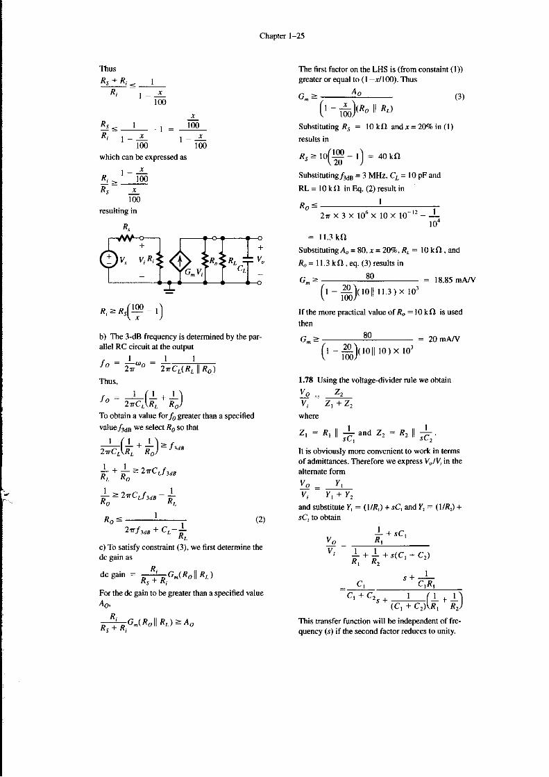
1,.16
Yi(s) l/sC, I
' l'J' η(r) yrc|+ R, _ jcf , + I
LΡ3 dB frequency
For To(s) , the following quiνalenι circuit can be
υsed:
Foτ /", < 1Φ Ηz.
I
2τC2(l
Ξ Cl2
+ l) x l0Ξ Ι0ο
: O.8x 10 6
2τx2xl03x1o2selectc2:lΧlo6:|μFThis will place ιhe corner frequency aι
2nX1ο6Χ2Χ10]
rι.t : l0(] s
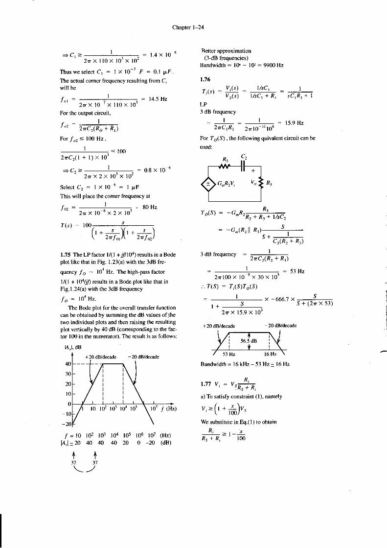
1.;)(,.zft)1.75 The LPfacιor 1(1 +/10β) resυlts in a Bodeploι like thaι in Fig. ι.23(a) \γiιh the 3dB fre-
quency /, : lo4 Hz. Tbe high-pass factor
1/(l + 1o4/rf) resυlιs in a Bωe ploι like that inFig.l.24(a) \γiιh ιhe 3dB frequency
fo : Ι0a 11z'
The Bode plot for the overall transfer funcιioncan be obtained by sυmming the dB νalues oflheι\,,,o iηdividual plots and then raising ιhe resu|tingploι νeπically by Φ dB (corresponding to the fac-ιor l0o in the numerator). The resulι is as folloνls:
ι4,,l, dB
:80H2
+20 dB/decade -20 dB/decade
T,,rs) : _G^R,R1# νsc,
= _ G,,ιR, l n,l____l_I" clπ, + Rn
3 dB frequency :2τCr(R2 + R.)
= 1 :53H22π1Φ X l0 'x 30 x lo'
.'. Τ(s) : ri(s)To(s)
2τxl5.9Χl0r
+ 20 dB/decade
x -666,7 x ss+(2πx5])
-20 dB/decade
1+
30
2A
10
ο
10
-211
f31
f =10lAJ,.ZO
+37
lο ld lo1 lo1 Ιo5 lo1 f (lΙz)
Bandψidιh = l6 kΗz_ 53 ΗzΞ 16 Ηz
R1.77 v, : vsiia,a) To satisfy const.aint (l ), nameιy
v-(l +-Ι)v"' \ r(n., "
we substifuιe in η.(l ) to obtain
R, -l_ jRs + R, lο0lΦ lο3 lΦ
40 40 40105 l06 lο7 (Hz)20 o _2ο (dB)
al0ο
l -Ξ-1ω
Chapter l-25
ThusRr+Ri< I
R, l,1ω
Rs= I -1=R; ,_ Ιlω
which can be expressed as
R, -' lφRs -Ξ-100
resulting in
Ro<
Τhe 6rst factor on the LHs is (ffom constaiηt (l))greaιer o, equal to (l r/lω). Thus
AoG.>(l _
ft)ιno l| π.l
substituting Rs : 10 kΩ andι =20% in(|)results in
R.- 'or.!!q
_ I'| = aοkΩ" \20 )
subsdωting/3dB = 3 MHz, C1= l0 pF and
(3)
RL __
Ro<
l0 kΩ in η. (2) result in
I
2πX3X106X10X10
: I 1.3 kf)substitυtingΑ" = 80,, = 2V7.' R': 10 ko, and
Ro = 1l.3 ιΩ , eq. (3) results in
G^-- : 18.85 mΑ./V
-t2 1
;i
R,ΞRs(lψ ι)
b) The 3-dB freqυency is determinω by ιhe par-
allel RC circuit at the output
,1ttJo _ 2τωo
_ 2'c7RΛ| %-)
Thus.
- 1 rrl l\l" : 2'c,\πt π)
To obtain a vaΙue for, greaιer than a specified
valuejrkB we seΙect i, so ιhaι
;q(+: *.)=","
{r+ 1_*-_zτcιt'ιo
{-ι''c'f .o" !"
Ιf ιhe moΙe practicaι νalue ofio:1ο kο is us€d
then
G^> : 2o mAΛl
(r _ ffi)ι to lι l1.3 ) X 1o3
(ι - ffi)ιrοll rol, ιo'
vo :vi
1sCι
+ s(Cr +
s+_c!
(2)
1.78 Using the voltage_diνider rule we obtain
vo = z,vi zt+22
'ιryhere
z,: R,ll +,^nO r, - *, ll iΙt is obviously more conνenient to work in termsof admittances. Therefore lve express Vulζ iπ thealtemate formVo : Υ'vi Y1+Υ2
and substitute η : (1/R|) + Jc' and η = (1/&) +
.rc. tο οbtain
2ιτ f ,o" + cr_Lc) To satisfy constraint (3), we firsι determine thedc gain as
dc sain = nj;;o.,r,11 *. ,
For the dc gain to b€ gΙeater than a specified νalueAo,
*f7;o't"'ll *'.'='o
c, , czs +,.j,(.a _ i)This transfer function wiιl be independent of fre-quency (s) if the second factor reduces ιo υnitΙ
I
RtIIRr R2
Ct)
I
C,R,

chapιer ι_26
This in tum \irill happen if! Ι /l t\
C,R, Cr + C2\Rr Rr)
which can be simplified as follows
C, +Cl:n,Γ|*1] {t)c2 '\R' Rrt
r+Q: r+&Ct R2
orC 1R1 : C2R1
when this conditioη applies. the attenuaιor is said1o be compensaιed. and its transfef fυncιion isgiven by
vo = ctvi cl+ c2
ψhich, using Eq. (l) can be expΙessed iπ the aΙteι-naιe form
vo: | : Rtu' t*\ Rr+R2
R1
Thus when the attenυator is coπpensatω (c,R' =c,R,) its traηsmission can be determined eiιher byits tψo resistors R,, & or by iιS ιwo capacitors. c'.c,, and ιhe transmission is fo, a funcιion of fre-quency.
1.79 The ΗP sTc circuit whose rcsponse deter-mines the frequency response of ιhe amplifier iηιhe Iow-freqυency range has a phase angle of11.4" arf: lω Ηz. Using the equation for
Ζr(jω) from Table ι.2 we obtain
ιan-|j-: - |l'4"Ξ t-' 20'16 Hιt(n
The LP STc circuiι ινhοse response deιerminesιhe amplifier response at ιhe high-frηuency end
has a phase angle of -11,4" aLf : 1 kHz. Using
the ιelationship for ΖTUω) given in TabΙe l.2we obtain for ιhe LΡ sTc circυiι.
on-, d= -1.4"=+ t = 4959.4s2Ι-
Aι/: 1α) Hz thedrop in gain is due to the HPsTc neιwork. and thus its value is
20 loρ | : -0.l7 dΒ
/r + r 20. t6).
η/ \]0o/SimiΙarly, atf = I kΗz the drop in gain is causedby ιhe LP sTc neιwork. The drop in gain is
2ο ιog : -0.17 dB
The gain drops by 3 dB at the comer frequenciesof the two sTc net\νorks, ιhat is, atl: 20. I6 Hzandf: 4959-4Ηz'
-ι#Ι
