ch 2 fundamentals lecture 2
TRANSCRIPT
7/23/2019 Ch 2 Fundamentals Lecture 2
http://slidepdf.com/reader/full/ch-2-fundamentals-lecture-2 1/36
Ch 2: Fundamentals of Kinematics
•
Topic outline.• 2.1 Degrees of Freedom (DOF) or Mobility.
• 2.2 Types of motion.
• 2.3 Mechanism
• Kinematic Chain and linkage.
•Links and joints and their classification types.
• 2.4 Drawing kinematic diagrams. – Read on own.
• 2.5 Mobility and Connectivity.
• 2.6 Mechanisms and Structures.
• 2.8 Paradoxes.
• 2.9 Isomers.
• 2.11 Intermittent motion.
• 2.12 Inversions.
• 2.13 The Grashoff’s condition – four Bar and Rotatebility
8/28/2014 1ME 320
7/23/2019 Ch 2 Fundamentals Lecture 2
http://slidepdf.com/reader/full/ch-2-fundamentals-lecture-2 2/36
Degrees of Freedom (DOF)
• The number of independent parameters (measurements) required to uniquelydefine a mechanical system’s position in space at any instant of time.
• In this course a mechanical system will consist of rigid bodies
( no deformation ).
• For an elastic body (deformable) there are infinite degrees of freedom and is called
a compliant system.• A rigid body in plane motion has three DOF consisting of a translation ( x, y ) and
rotation (θ).
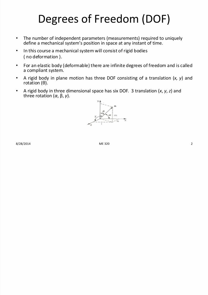
• A rigid body in three dimensional space has six DOF. 3 translation ( x , y , z) andthree rotation (α, β, γ ).
8/28/2014 2ME 320
7/23/2019 Ch 2 Fundamentals Lecture 2
http://slidepdf.com/reader/full/ch-2-fundamentals-lecture-2 3/36
Types of motion
•
General 3D motion:• Rotation about any axis and also simultaneous translation.
• Planar (2D) motion:
• Rotation about one axis and also simultaneous translation.
•
Pure rotation:• A center of rotation (point with no translation).
• All other points describe arcs about that center.
• Pure translation:
• All points on the body describe a parallel paths (curvilinear or rectilinear).
• A reference line on the body changes linear position and not angularorientation.
• Complex motion:
• A simultaneous combination of rotation and translation.
8/28/2014 3ME 320
7/23/2019 Ch 2 Fundamentals Lecture 2
http://slidepdf.com/reader/full/ch-2-fundamentals-lecture-2 4/36
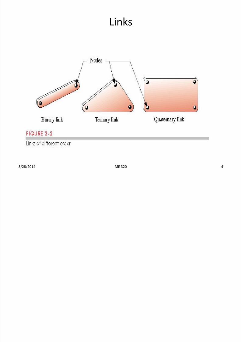
Links
8/28/2014 4ME 320
7/23/2019 Ch 2 Fundamentals Lecture 2
http://slidepdf.com/reader/full/ch-2-fundamentals-lecture-2 5/36
Joints
• Kinematic pairs: A connection between two or more links at
their nodes, which allow relative motion in some directions
while constraining motion in others.
• Classification of joints:
1. Type of contact between the elements (lower or higher pair)
2. Number of DOF allowed at the joint (connectivity).
3. Type of physical closure of the joint (force or form closed).4. Number of links joined (order of the joint).
8/28/2014 5ME 320
7/23/2019 Ch 2 Fundamentals Lecture 2
http://slidepdf.com/reader/full/ch-2-fundamentals-lecture-2 6/36
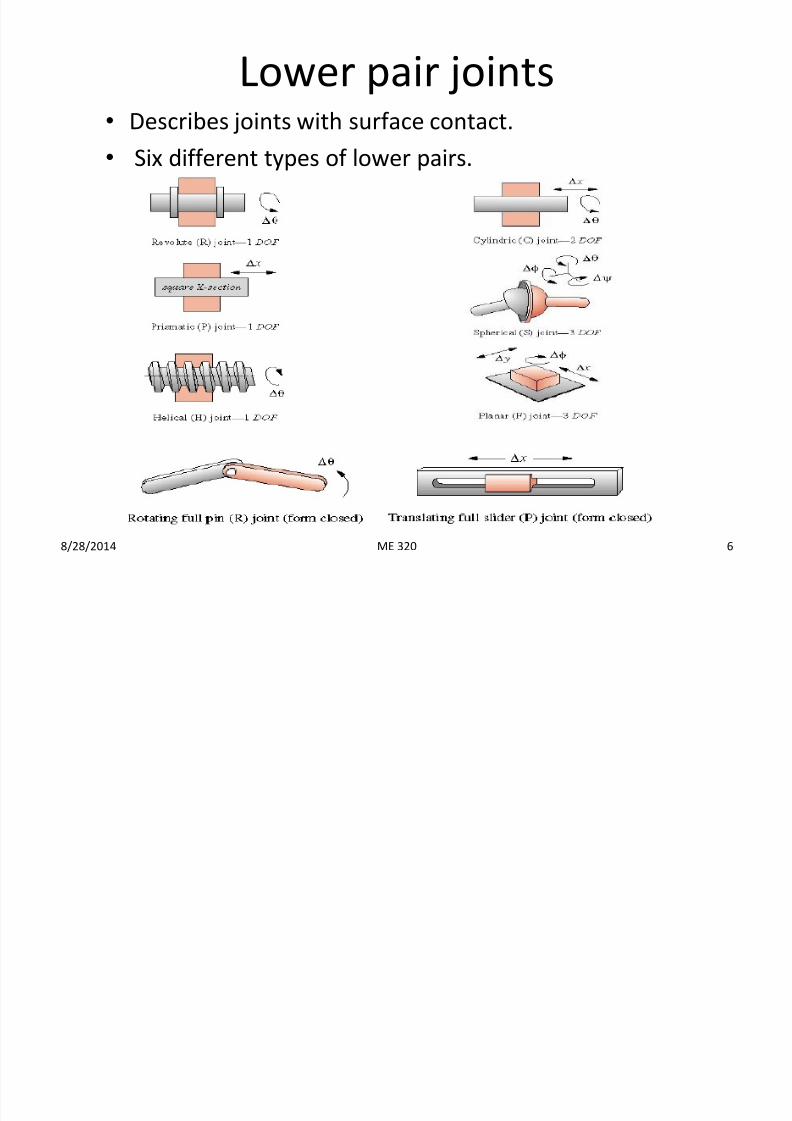
Lower pair joints• Describes joints with surface contact.
• Six different types of lower pairs.
8/28/2014 6ME 320
7/23/2019 Ch 2 Fundamentals Lecture 2
http://slidepdf.com/reader/full/ch-2-fundamentals-lecture-2 7/36
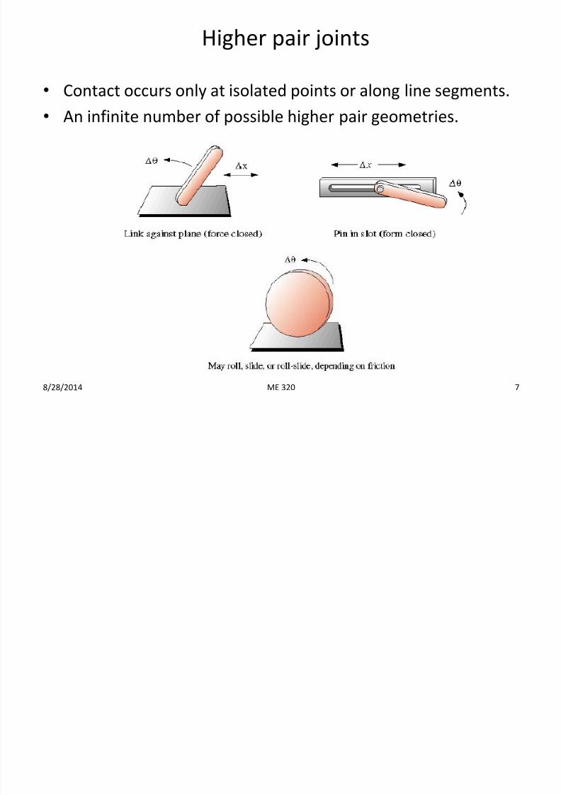
Higher pair joints
•
Contact occurs only at isolated points or along line segments.• An infinite number of possible higher pair geometries.
8/28/2014 7ME 320
7/23/2019 Ch 2 Fundamentals Lecture 2
http://slidepdf.com/reader/full/ch-2-fundamentals-lecture-2 8/36
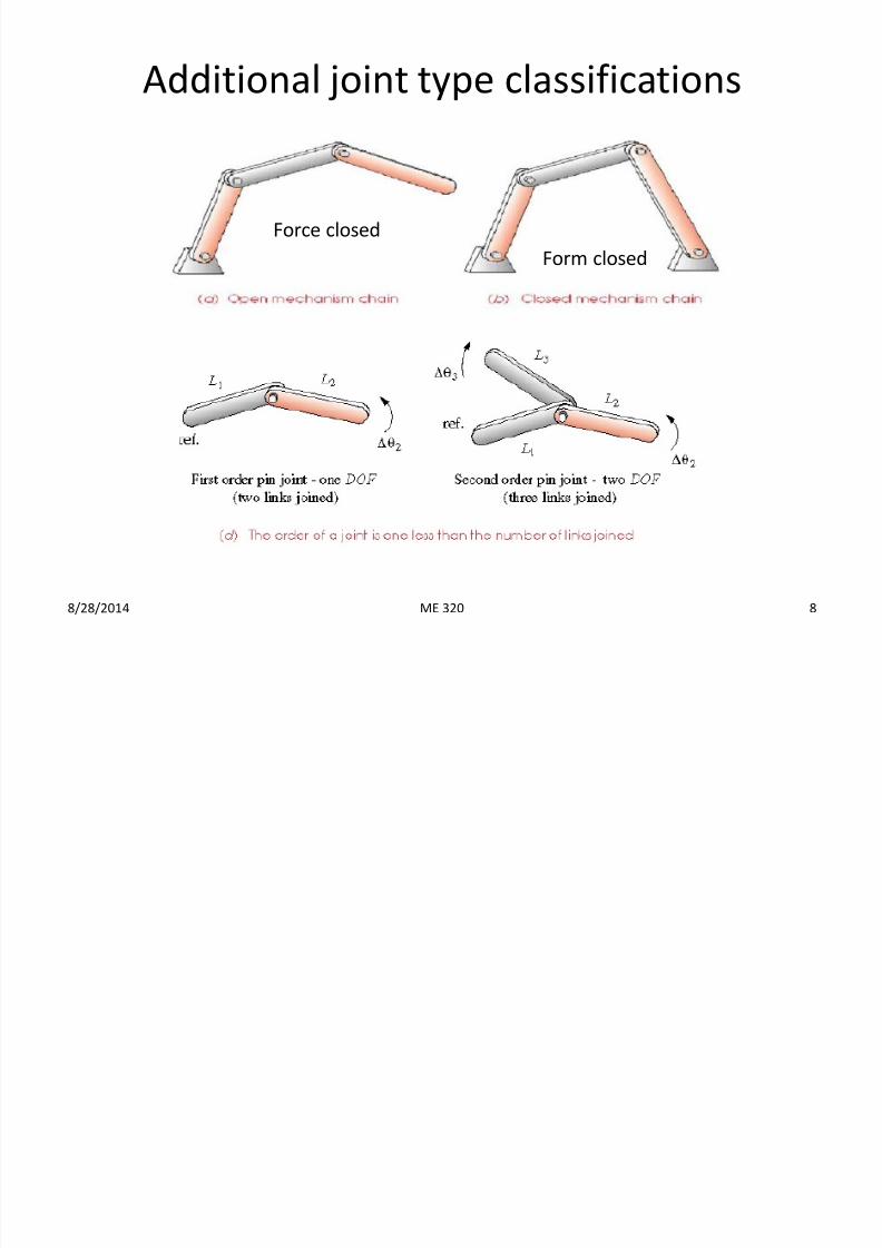
Additional joint type classifications
8/28/2014 8
Force closed
Form closed
ME 320
7/23/2019 Ch 2 Fundamentals Lecture 2
http://slidepdf.com/reader/full/ch-2-fundamentals-lecture-2 9/36
Kinematic chain, mechanism, and machine
• Kinematic chain: Assemblage of links and joints interconnected in a way
to provide a controlled output motion in response to a supplied input
motion.
•
Mechanism (or linkage): A closed kinematic chain in which at least onelink has been “grounded” or attached to a frame of reference. From
Chapter 1, a mechanism was defined as a system of elements arranged to
transmit motion in a predetermined fashion.
•Machine: – A collection of mechanisms arranged to transmit forces and do work.
– A combination of resistant bodies to compel the mechanical forces of nature
to do work accompanied by determinate motions.
8/28/2014 9ME 320
7/23/2019 Ch 2 Fundamentals Lecture 2
http://slidepdf.com/reader/full/ch-2-fundamentals-lecture-2 10/36
Some definitions• DOF of a single rigid body: Number of independent parameters required
to uniquely define the position of the body with respect to a given
reference frame.
• DOF of a system of rigid bodies: Number of independent parameters
required to uniquely define the position of all the members of the system.
• Connectivity: Number of DOF of a joint between two rigid bodies.
• Mobility: Number of DOF of a system of linkages.
• The mobility of a mechanism is the minimum number of coordinates
needed to specify the positions of all the members of the mechanism
relative to the frame.• The mobility of a mechanism is the number of inputs that need to be
provided in order to create a predictable output.
8/28/2014 10ME 320
7/23/2019 Ch 2 Fundamentals Lecture 2
http://slidepdf.com/reader/full/ch-2-fundamentals-lecture-2 11/36
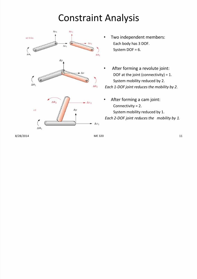
Constraint Analysis
• Two independent members:
Each body has 3 DOF.
System DOF = 6.
• After forming a revolute joint:
DOF at the joint (connectivity) = 1.
System mobility reduced by 2.
Each 1-DOF joint reduces the mobility by 2.
•After forming a cam joint:
Connectivity = 2.
System mobility reduced by 1.
Each 2-DOF joint reduces the mobility by 1.
8/28/2014 11ME 320
7/23/2019 Ch 2 Fundamentals Lecture 2
http://slidepdf.com/reader/full/ch-2-fundamentals-lecture-2 12/36
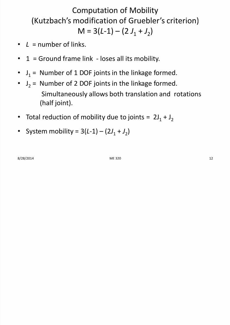
Computation of Mobility
(Kutzbach’s modification of Gruebler’s criterion)
M = 3(L-1) – (2 J1 + J2)
• L = number of links.
• 1 = Ground frame link - loses all its mobility.
• J1 = Number of 1 DOF joints in the linkage formed.
• J2 = Number of 2 DOF joints in the linkage formed.
Simultaneously allows both translation and rotations
(half joint).
• Total reduction of mobility due to joints = 2J1 + J2
• System mobility = 3(L-1) – (2 J1 + J2)
8/28/2014 12ME 320
7/23/2019 Ch 2 Fundamentals Lecture 2
http://slidepdf.com/reader/full/ch-2-fundamentals-lecture-2 13/36
ME 320 13
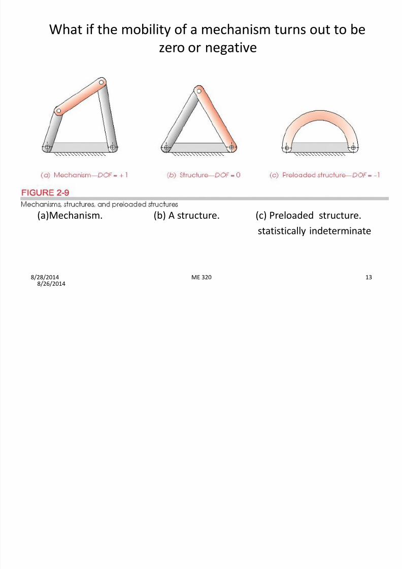
What if the mobility of a mechanism turns out to be
zero or negative
8/26/2014
(a)Mechanism. (b) A structure. (c) Preloaded structure.
statistically indeterminate
8/28/2014
7/23/2019 Ch 2 Fundamentals Lecture 2
http://slidepdf.com/reader/full/ch-2-fundamentals-lecture-2 14/36
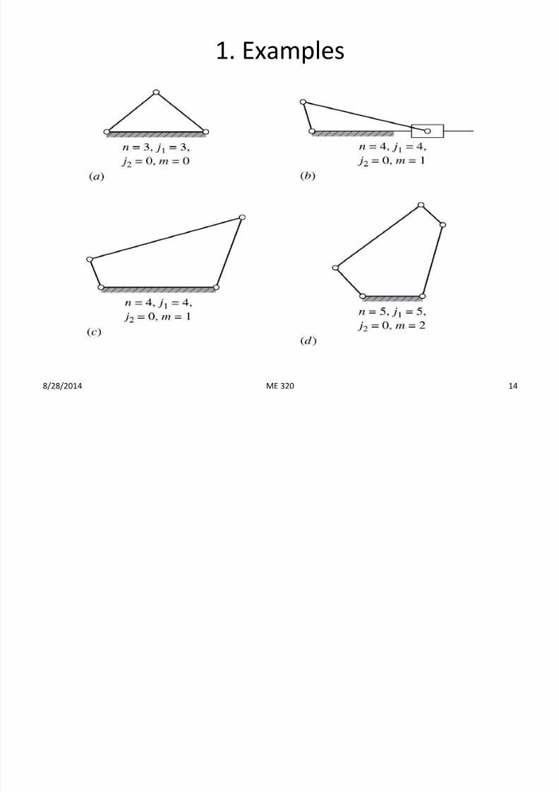
1. Examples
8/28/2014 14ME 320
7/23/2019 Ch 2 Fundamentals Lecture 2
http://slidepdf.com/reader/full/ch-2-fundamentals-lecture-2 15/36
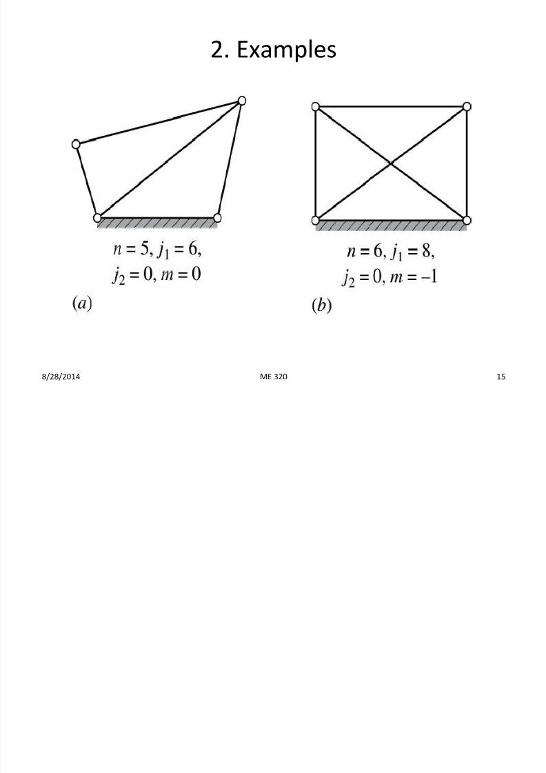
2. Examples
8/28/2014 15ME 320
7/23/2019 Ch 2 Fundamentals Lecture 2
http://slidepdf.com/reader/full/ch-2-fundamentals-lecture-2 16/36
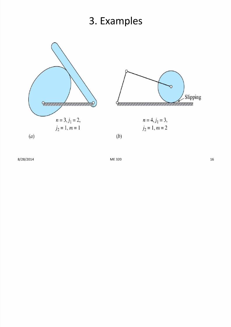
3. Examples
8/28/2014 16ME 320
7/23/2019 Ch 2 Fundamentals Lecture 2
http://slidepdf.com/reader/full/ch-2-fundamentals-lecture-2 17/36
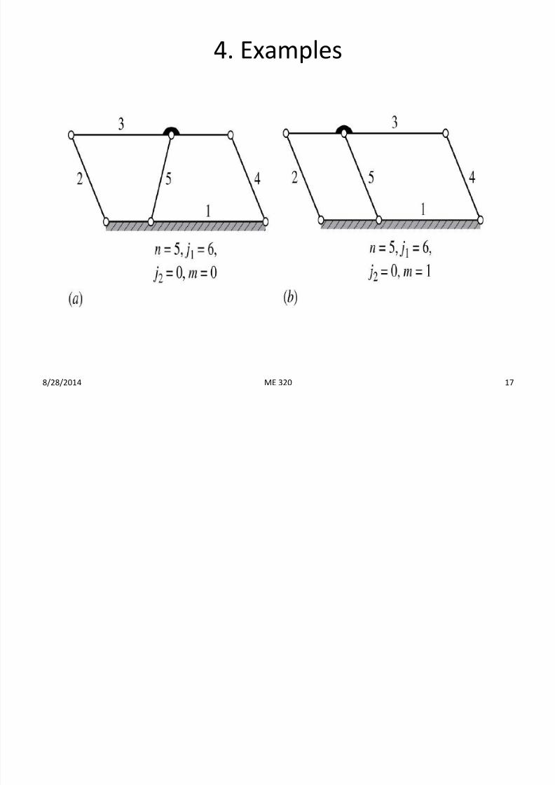
4. Examples
8/28/2014 17ME 320
7/23/2019 Ch 2 Fundamentals Lecture 2
http://slidepdf.com/reader/full/ch-2-fundamentals-lecture-2 18/36
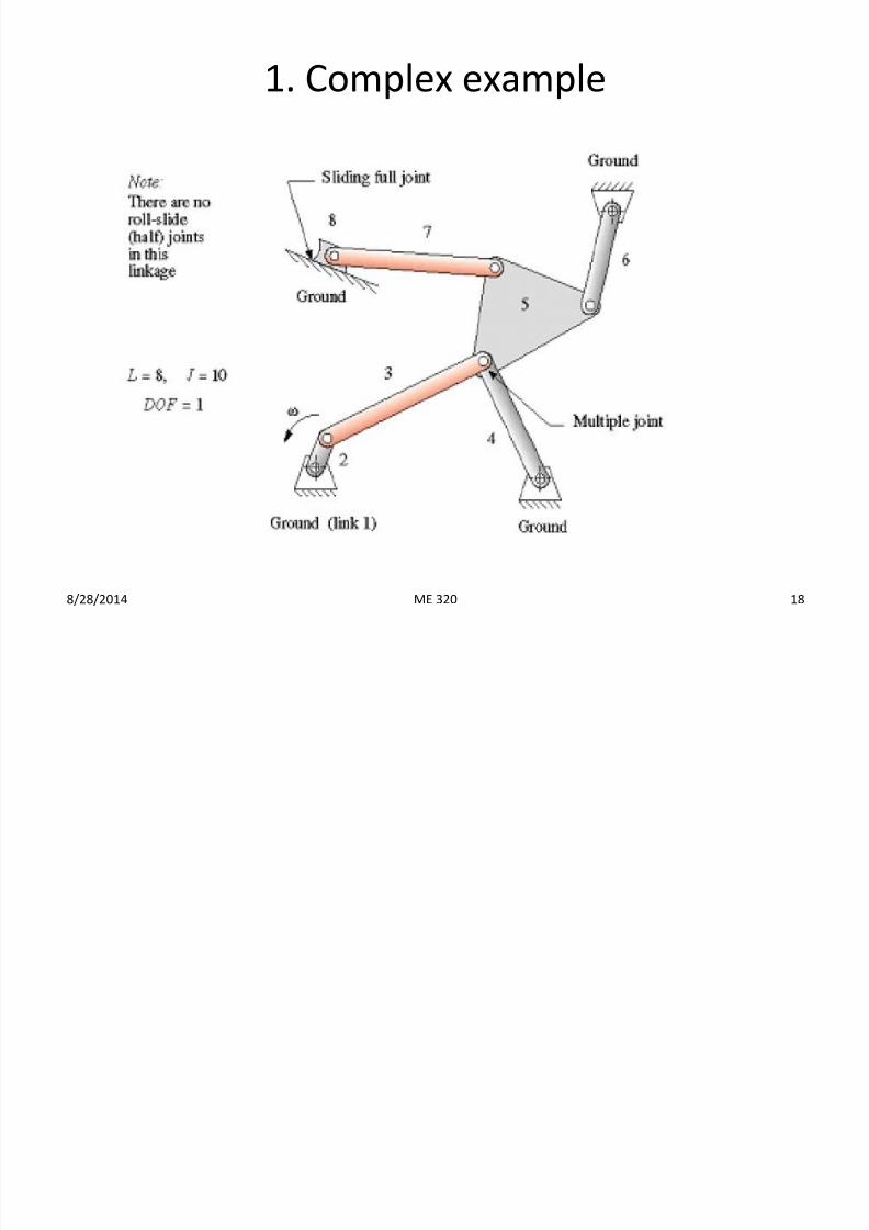
1. Complex example
8/28/2014 18ME 320
7/23/2019 Ch 2 Fundamentals Lecture 2
http://slidepdf.com/reader/full/ch-2-fundamentals-lecture-2 19/36
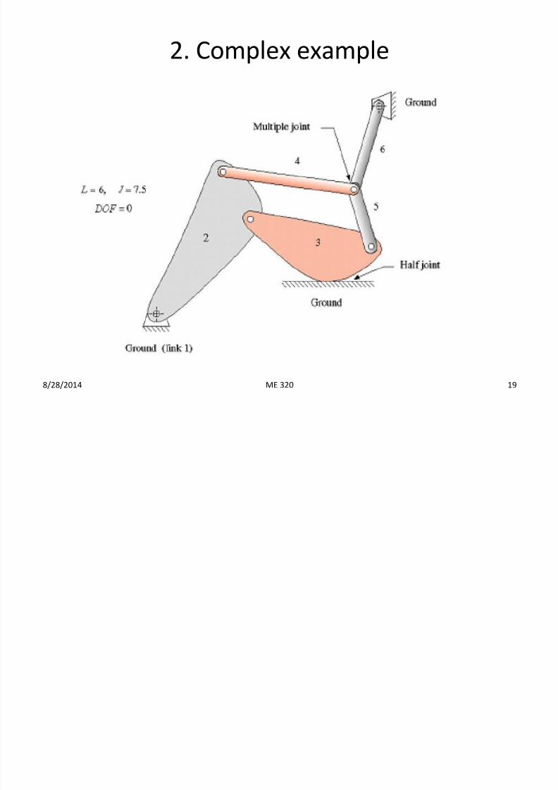
2. Complex example
8/28/2014 19ME 320
7/23/2019 Ch 2 Fundamentals Lecture 2
http://slidepdf.com/reader/full/ch-2-fundamentals-lecture-2 20/36
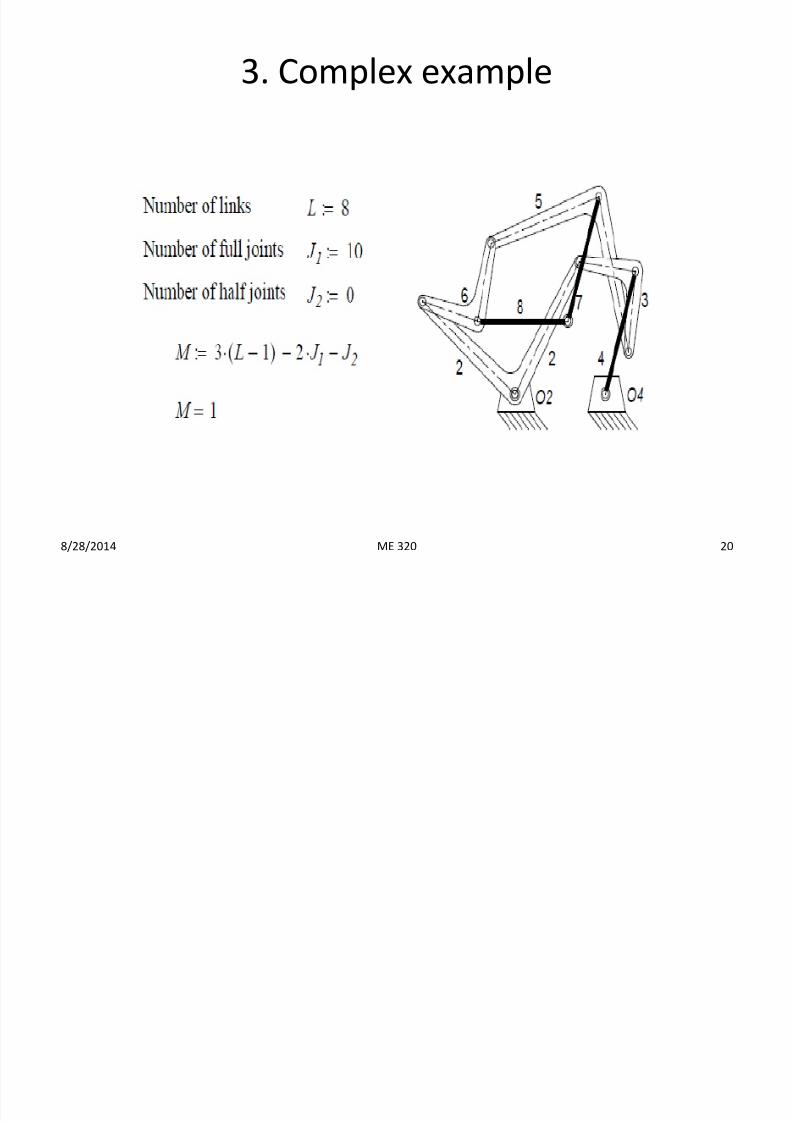
3. Complex example
8/28/2014 20ME 320
7/23/2019 Ch 2 Fundamentals Lecture 2
http://slidepdf.com/reader/full/ch-2-fundamentals-lecture-2 21/36
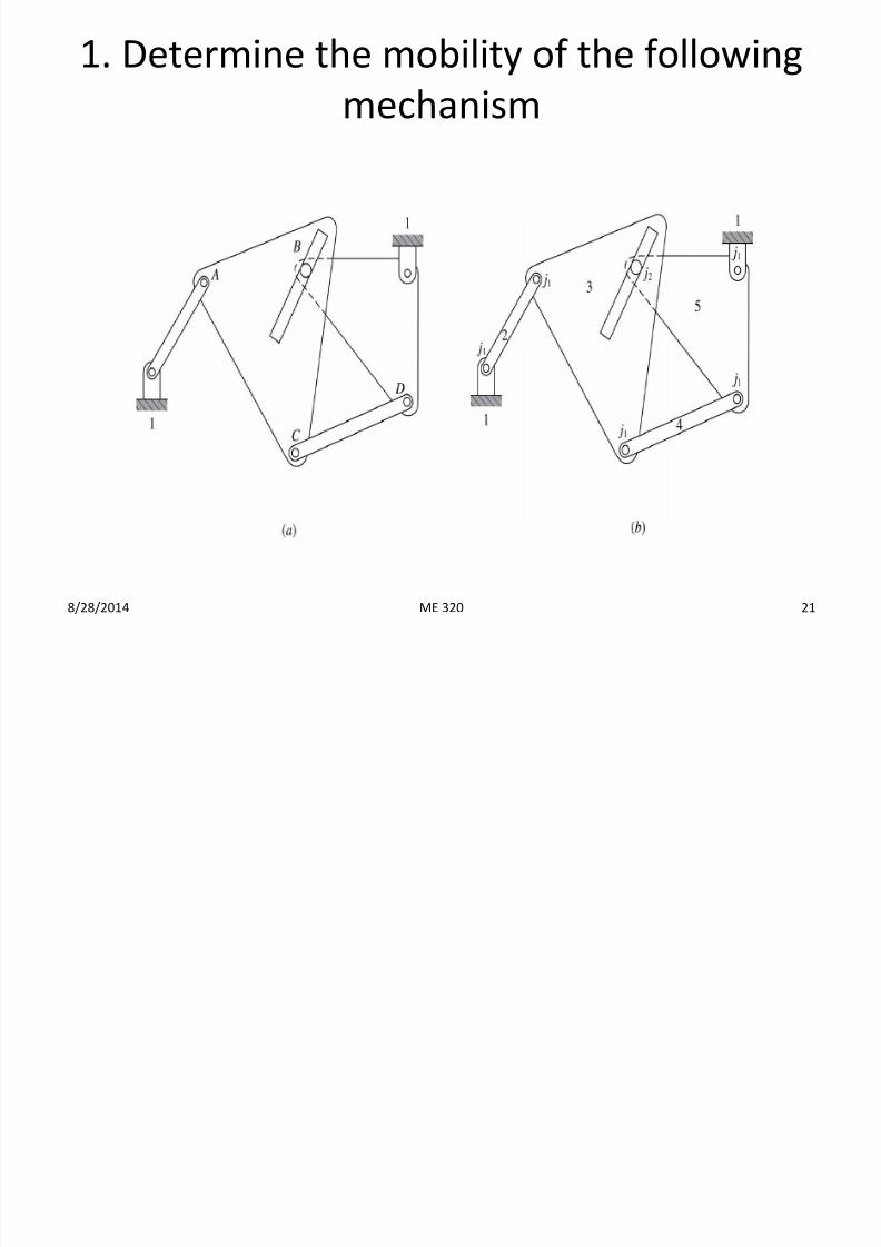
1. Determine the mobility of the following
mechanism
8/28/2014 21ME 320
7/23/2019 Ch 2 Fundamentals Lecture 2
http://slidepdf.com/reader/full/ch-2-fundamentals-lecture-2 22/36
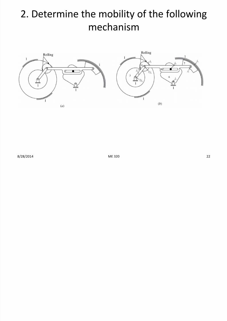
2. Determine the mobility of the following
mechanism
8/28/2014 22ME 320
7/23/2019 Ch 2 Fundamentals Lecture 2
http://slidepdf.com/reader/full/ch-2-fundamentals-lecture-2 23/36
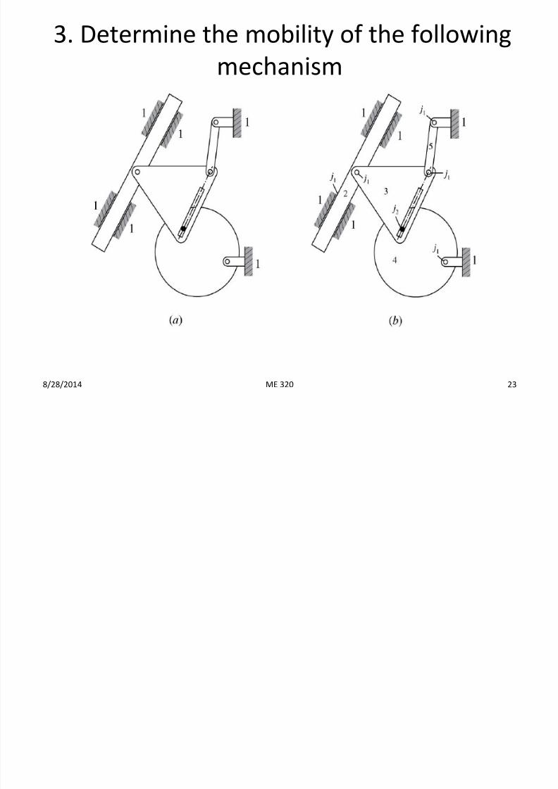
3. Determine the mobility of the following
mechanism
8/28/2014 23ME 320
7/23/2019 Ch 2 Fundamentals Lecture 2
http://slidepdf.com/reader/full/ch-2-fundamentals-lecture-2 24/36
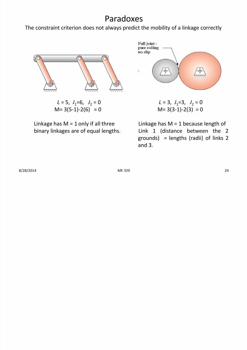
ParadoxesThe constraint criterion does not always predict the mobility of a linkage correctly
L = 5, J1=6, J2 = 0
M= 3(5-1)-2(6) = 0
Linkage has M = 1 only if all three
binary linkages are of equal lengths.
L = 3, J1=3, J2 = 0
M= 3(3-1)-2(3) = 0
Linkage has M = 1 because length of
Link 1 (distance between the 2
grounds) = lengths (radii) of links 2
and 3.
8/28/2014 24ME 320
7/23/2019 Ch 2 Fundamentals Lecture 2
http://slidepdf.com/reader/full/ch-2-fundamentals-lecture-2 25/36
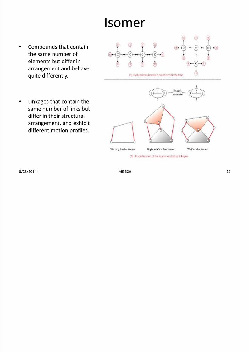
Isomer
• Compounds that contain
the same number of
elements but differ in
arrangement and behave
quite differently.
• Linkages that contain the
same number of links but
differ in their structural
arrangement, and exhibit
different motion profiles.
8/28/2014 25ME 320
7/23/2019 Ch 2 Fundamentals Lecture 2
http://slidepdf.com/reader/full/ch-2-fundamentals-lecture-2 26/36
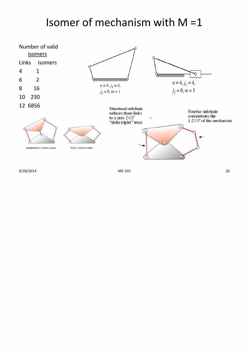
Isomer of mechanism with M =1
Number of valid
isomers
Links isomers
4 1
6 2
8 16
10 230
12 6856
8/28/2014 26ME 320
7/23/2019 Ch 2 Fundamentals Lecture 2
http://slidepdf.com/reader/full/ch-2-fundamentals-lecture-2 27/36
8/28/2014 27
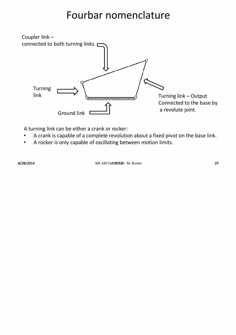
Fourbar nomenclature
Coupler link –
connected to both turning links.
8/26/2014 ME 320 Fall 2012 - M. Brown 27
Turning link – Output
Connected to the base by
a revolute joint.
Turning
link
Ground link
A turning link can be either a crank or rocker:
• A crank is capable of a complete revolution about a fixed pivot on the base link.
• A rocker is only capable of oscillating between motion limits.
ME 320
7/23/2019 Ch 2 Fundamentals Lecture 2
http://slidepdf.com/reader/full/ch-2-fundamentals-lecture-2 28/36
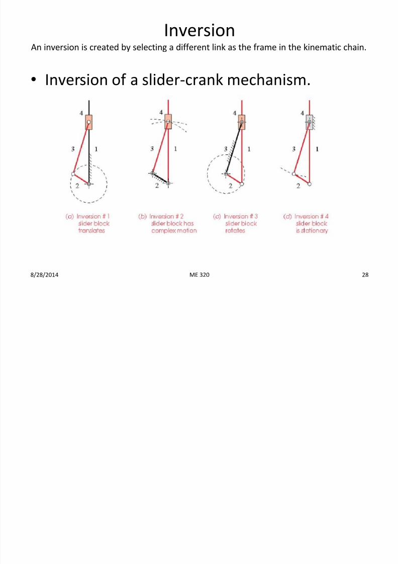
InversionAn inversion is created by selecting a different link as the frame in the kinematic chain.
• Inversion of a slider-crank mechanism.
8/28/2014 28ME 320
7/23/2019 Ch 2 Fundamentals Lecture 2
http://slidepdf.com/reader/full/ch-2-fundamentals-lecture-2 29/36
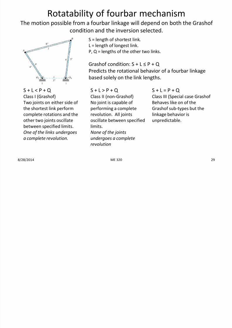
Rotatability of fourbar mechanismThe motion possible from a fourbar linkage will depend on both the Grashof
condition and the inversion selected.
S = length of shortest link.L = length of longest link.
P, Q = lengths of the other two links.
8/28/2014 29
Grashof condition: S + L ≤ P + Q
Predicts the rotational behavior of a fourbar linkage
based solely on the link lengths.
S + L < P + Q Class I (Grashof)
Two joints on either side of
the shortest link perform
complete rotations and the
other two joints oscillatebetween specified limits.
One of the links undergoes
a complete revolution.
S + L > P + Q Class II (non-Grashof)
No joint is capable of
performing a complete
revolution. All joints
oscillate between specifiedlimits.
None of the joints
undergoes a complete
revolution
S + L = P + Q Class III (Special case Grashof
Behaves like on of the
Grashof sub-types but the
linkage behavior is
unpredictable.
ME 320
7/23/2019 Ch 2 Fundamentals Lecture 2
http://slidepdf.com/reader/full/ch-2-fundamentals-lecture-2 30/36
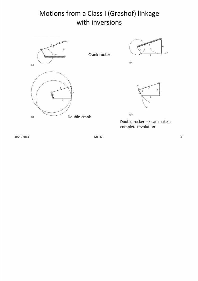
Motions from a Class I (Grashof) linkage
with inversions
8/28/2014 30
Crank-rocker
Double-rocker – s can make a
complete revolution
Double-crank
ME 320
7/23/2019 Ch 2 Fundamentals Lecture 2
http://slidepdf.com/reader/full/ch-2-fundamentals-lecture-2 31/36
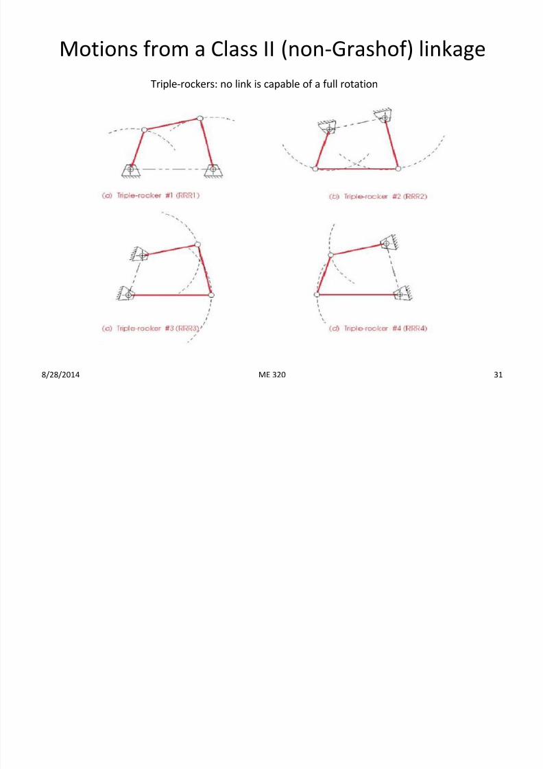
Motions from a Class II (non-Grashof) linkage
8/28/2014 31
Triple-rockers: no link is capable of a full rotation
ME 320
7/23/2019 Ch 2 Fundamentals Lecture 2
http://slidepdf.com/reader/full/ch-2-fundamentals-lecture-2 32/36
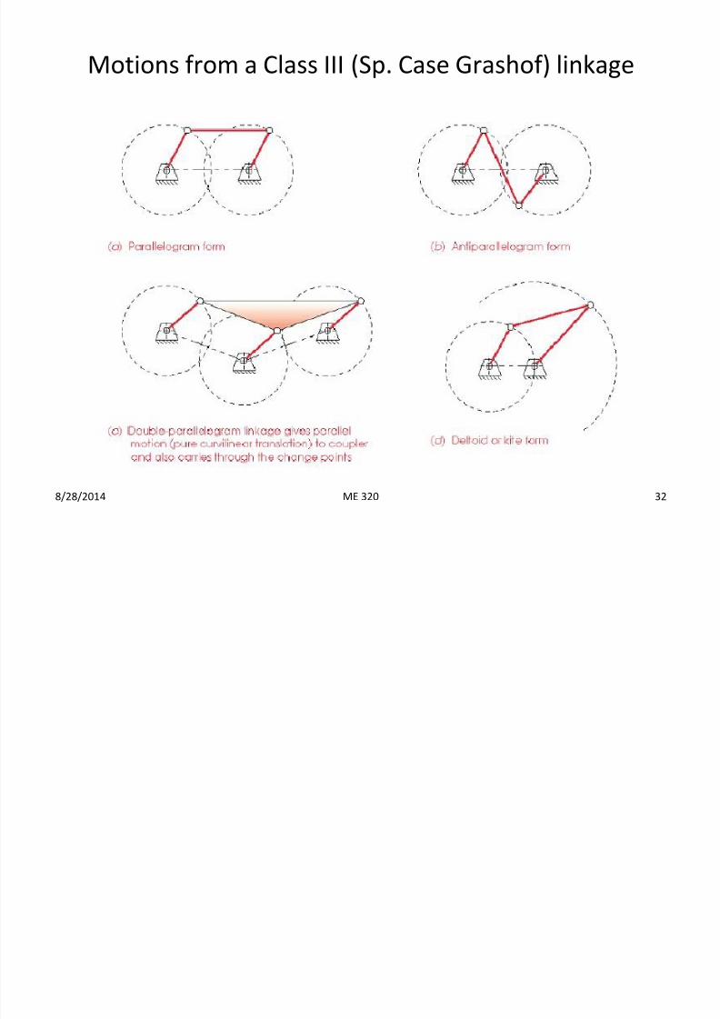
Motions from a Class III (Sp. Case Grashof) linkage
8/28/2014 32ME 320
7/23/2019 Ch 2 Fundamentals Lecture 2
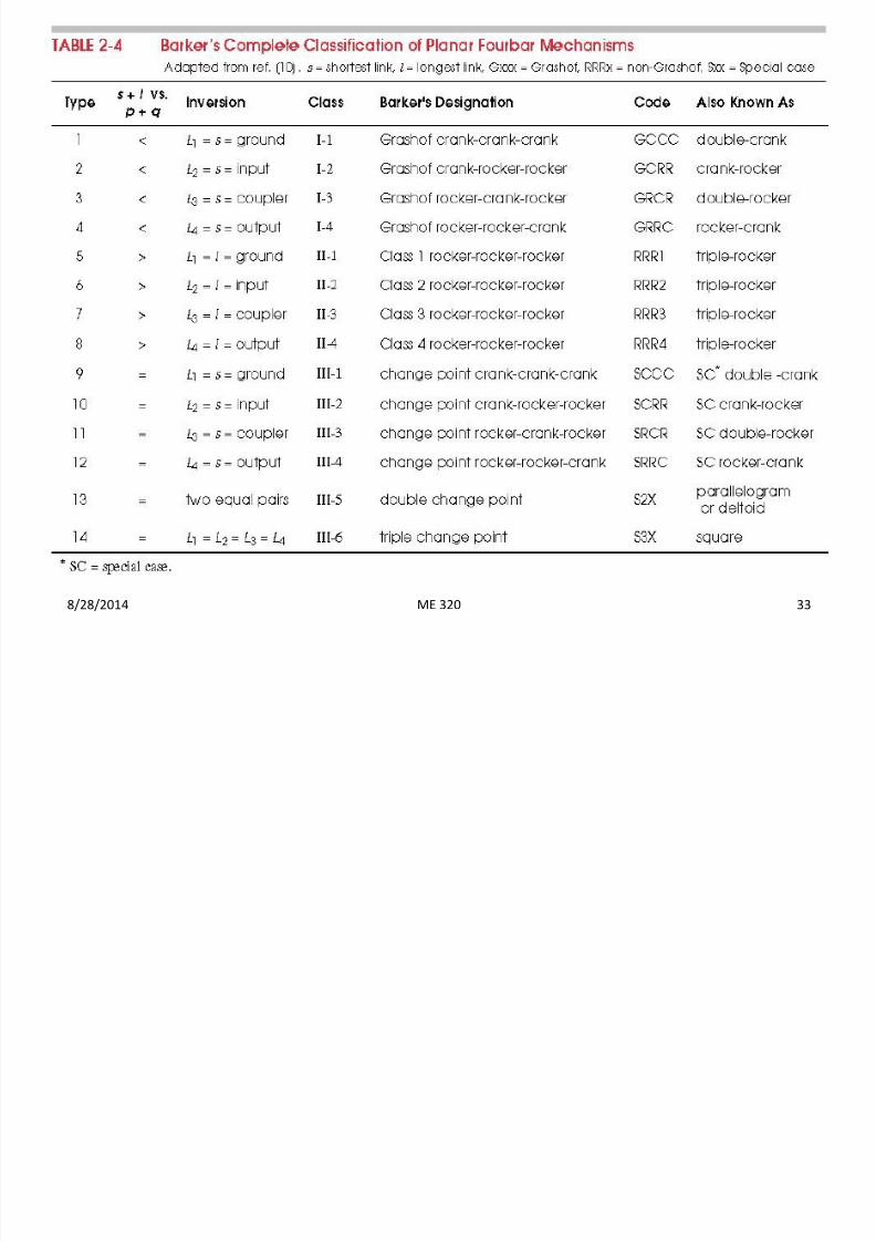
http://slidepdf.com/reader/full/ch-2-fundamentals-lecture-2 33/36
8/28/2014 33ME 320
7/23/2019 Ch 2 Fundamentals Lecture 2
http://slidepdf.com/reader/full/ch-2-fundamentals-lecture-2 34/36
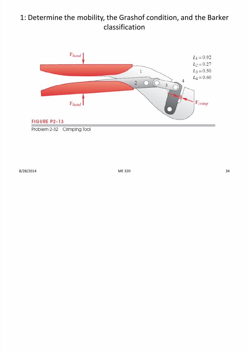
1: Determine the mobility, the Grashof condition, and the Barker
classification
8/28/2014 34ME 320
7/23/2019 Ch 2 Fundamentals Lecture 2
http://slidepdf.com/reader/full/ch-2-fundamentals-lecture-2 35/36
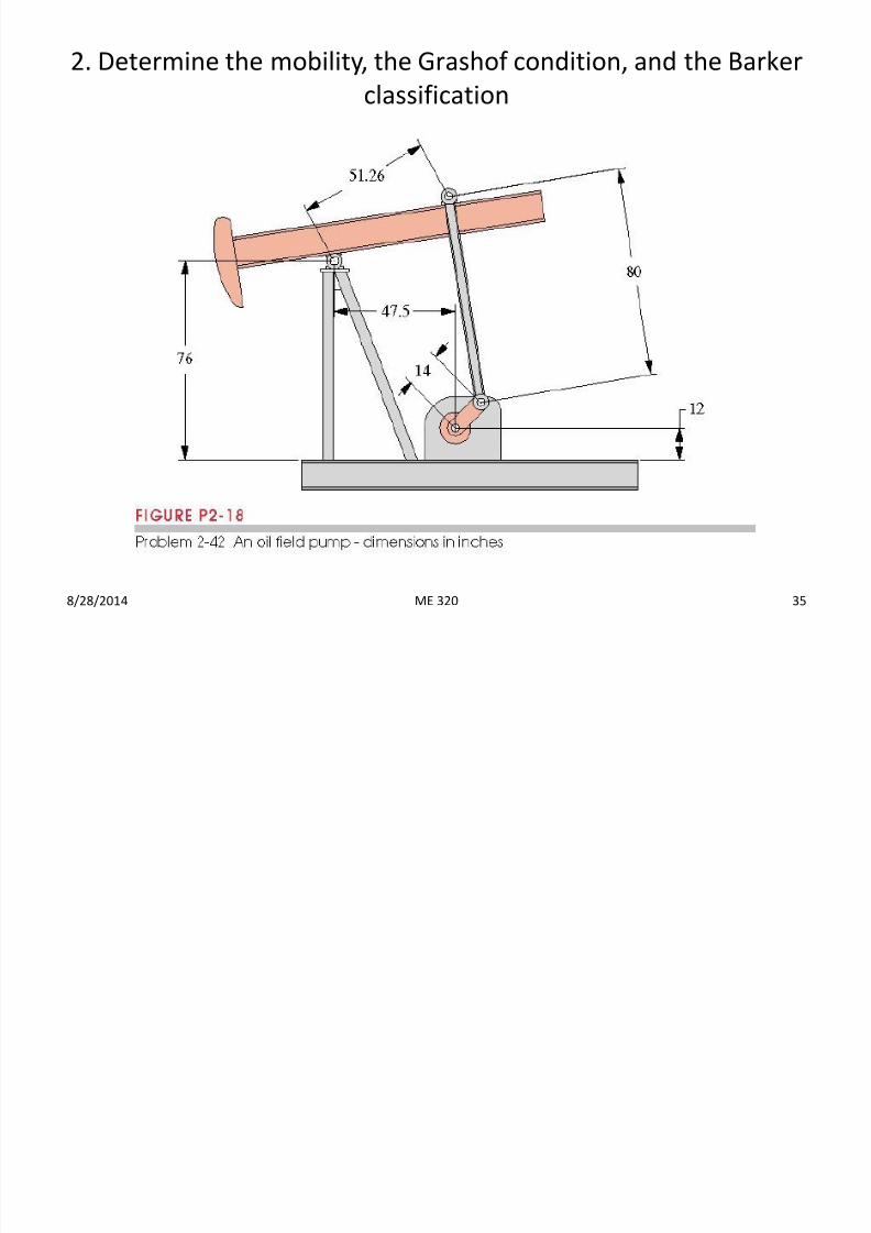
2. Determine the mobility, the Grashof condition, and the Barker
classification
8/28/2014 35ME 320
7/23/2019 Ch 2 Fundamentals Lecture 2
http://slidepdf.com/reader/full/ch-2-fundamentals-lecture-2 36/36
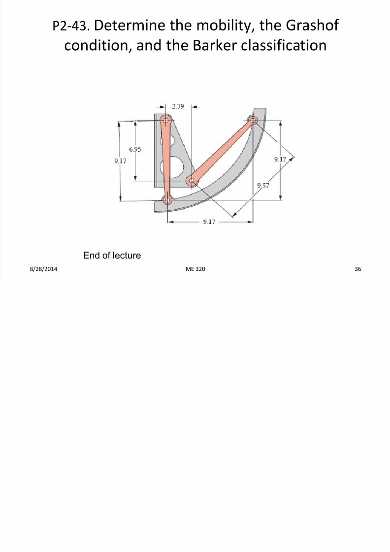
P2-43. Determine the mobility, the Grashof
condition, and the Barker classification
8/28/2014 36
End of lecture
ME 320