ch.2 assembly language programming - 홍익대학교...
TRANSCRIPT

Department of Electrical EngineeringUniversity of Arkansas
ELEG3923 MicroprocessorCh.2 Assembly Language Programming
Dr. Jingxian [email protected]

2
OUTLINE
• Inside 8051
• Introduction to assembly programming
• Program counter and ROM space
• PSW register and flag bits
• Register bank and stack
3
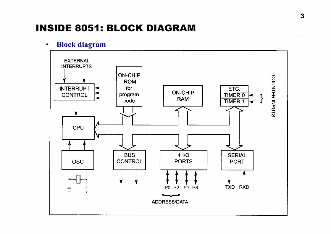
INSIDE 8051: BLOCK DIAGRAM• Block diagram

4
INSIDE 8051: REGISTERS• Registers (inside CPU)
– Most widely used registers:• 8-bit registers: A (accumulator), B, R0 ~ R7, PSW (program status word)• 16-bit registers: DPTR (data pointer), PC (Program counter)
– Most registers are 8-bit• The bits inside one register are designated as 7, 6, 5, 4, 3, 2, 1, 0• MSB (most significant bit): bit 7• LSB (least significant bit): bit 0
7 6 5 4 3 2 1 0an 8-bit register:

5
OUTLINE
• Inside 8051
• Introduction to assembly programming
• Program counter and ROM space
• PSW register and flag bits
• Register bank and stack

6
ASSEMBLY: MOV• MOV
– MOV destination, source• Copies data from source to destination
– Example:• MOV A, #55H ; load 55H into reg. A• MOV R0, A ; copy contents of A into R0• MOV R3, #16 ; load 16 into R3• MOV A, R3 ; copy contents of R3 into A
– Notes:• Immediate number: a regular constant number, always prefixed by a pound
sign #.• A post-fix of ‘H’ means this is a hex number
– Opcode v.s. Mnemonics• The Opcode for “MOV A, #55H” is: 01110100 01010101 (74H 55H) • CPU will only understand Opcode (machine code)• MOV is called the mnemonic for Opcode � easy to remember, easy to read.• Mnemonics will be translated to Opcode by an assembler.
Comments

7
ASSEMBLY: RUN PROGRAM• Assembling and running an 8051 program (Demo)
– 1. Use an editor to type in your assembly program (source file)• Usually has an extension of *.asm, *.a51
– 2. Assembler• An assembler program converts the mnemonics into binary machine code
that can be understood by the MCU.• Assembler will generate two files
– 1) list file (*.lst)» Optional. List all the instructions and addresses.» Helpful for program development
– 2) object file (*.obj)» Binary file contains the binary machine code
– 3. Linker• Combine one or more obj files into an absolute object file (no extension)
– 4. Object to hex converter• Convert absolute obj file to a file with extension “hex”, which can be
burned into the ROM of the MCU.– 5. Burn the HEX file to 8051.

ASSEMBLY: DEVELOPMENT ENVIRONMENT• Host
– The PC used to develop the program, it usually has• Editor (edit source file)• Compiler (convert high level language to machine code *.obj)• Assembler (convert assembly language to machine code *.obj)• Linker (link several obj files into an absolute obj file)• Obj to Hex converter (convert obj file to Hex file)• Loader (load the hex file to target)
• Target– The development hardware with embedded microcontroller.– It can be connected to Host through various interfaces
• E.g. RS232, USB, JTAG, IEEE1394, ……
8
Host Target

ASSEMBLY: MOV• Some additional notes about MOV (Cont’d)
– MOV #0F3H• If the number starts with a letter, put ‘0’ in front of it.
– MOV A, #7F2H ; possible error• Why?
– MOV A, #257 ; possible error• Why?
– MOV A, #34H is different from MOV A, #34– MOV A, #34H is different from MOV A, 34H
• We will discuss the meaning of MOV A, 34H later.
9

ASSEMBLY: ADD• ADD
– ADD A, source• Add the contents in Reg. A with source, and store the result in A• Review: Reg. A is also called accumulator• Destination must be A!!!
– Examples• 1. MOV A, #25H ;load 25H into A
MOV R2, #34H ;load 34H into R2ADD A, R2 ; A = A + R2
• 2. MOV R1, #0F5H ;load F5H into A (demo)MOV A, #0 ;load 0 into AADD A, R1 ; ADD A, #34 ; what is the value of A after this operation?
– Be careful of overflow (the result requires more than 8 bits)!• Only the lower 8 bits will be stored in register A• The carry flag in the PSW (program status word) register will be set if an
overflow happens (we will talk about PSW later this chapter).
10

ASSEMBLY: STRUCTURE• Structures of assembly language
– 1. A series of lines of assembly language instructions and/or directives– 2. An assembly language instruction consists of up to 4 fields
[label:] mnemonic [operands] [;comments]• Label: allows the program to refer to a line of code by name
– E.g. HERE: SJMP HERE• Mnemonic and operands
– The combination of mnemonic and operands will be translated to binary machine code
– E.g. MOV A, #23H ;Opcode: 0111 0100 0010 0011 (7423H)
MOV A 23H
11

ASSEMBLY: DIRECTIVES• Directives
– A pseudo-code that cannot be translated into machine code– Used to notify assembler of certain operations
• E.g. END: notify assembler the end of the source file.• Commonly used directives
– ORG: origin• Indicate the beginning of the address• The number after ORG can be either in hex or decimal
– DB: define byte (demo directives)• Define an 8-bit data

ASSEMBLY: DIRECTIVES• Commonly used directives
– EQU: equate• Define a constant without occupying a memory location• It DOES NOT use any memory space!• The constant value can be used later in the program
– To improve the readability of the program» Give a name to a constant
– To improve code efficiency» If the same constants are used twice in the program, with the
EQU directive, we only need to change it in one location if its value is changed
» We should avoid using constant directly, and use the EQU directive as often as possible.
• Example (Demo directives)COUNT EQU 25HMOV R3, #COUNTMOV A, #COUNT

14
OUTLINE
• Inside 8051
• Introduction to assembly programming
• Program counter and ROM space
• PSW register and flag bits
• Register bank and stack

ROM SPACE: PROGRAM COUNTER• Program counter (PC)
– A 16-bit register inside 8051 that points to the ROM address of the next instruction to be executed
– Every time the CPU fetches the opcode from the program ROM, the PC will be automatically incremented to point to the next instruction
• If the current opcode is one byte, PC will be incremented by 1 (Demo PC)– E.g. MOV A, R5, Opcode: 1110 1101 (EDH)
n=5MOV Rn
• If the current opcode is two bytes, PC will be incremented by 2 (Demo PC)– E.g. MOV A, #0H, Opcode 0111 0100 0000 0000 (7400H)
MOV A 00H
15

ROM SPACE: PROGRAM COUNTER• Program counter (Cont’d)
– When 8051 wakesup, the PC has an initial value of 0000H• We must put our initial program at location 0000H• What will happen if our program is not at 0000H? (Demo PC)
• ROM space– ROM is used to store program � it’s accessed by PC.– Address range that can be accessed by program counter
• PC has 16-bits – Start address: 0000H (0000 0000 0000 0000)– Maximum end address: FFFFH (1111 1111 1111 1111)– Each address corresponds to 1 byte
• The maximum ROM space that can be accessed by PC is: 64 KB• Most 8051 chips have a ROM size less than 64 KB
16

ROM SPACE: EXAMPLE• ROM space examples
– 1. Dallas Semiconductor DS89C430 has 16KB on chip ROM. Write down the ROM address range in hex format.
– 2. The ROM address range of Atmel AT89C51 is 0000H to 0FFFFH. What is size of the ROM in AT89C51
17

18
OUTLINE
• Inside 8051
• Introduction to assembly programming
• Program counter and ROM space
• PSW register and flag bits
• Register bank and stack

PSW:• PSW: program status word register
– An 8-bit register used to indicate the status of the program and uC.• Only 6 bits are used by 8051• The 2 remaining bits can be used by users (programmers).
– Also called flag register.– 4 conditional flags: indicate some conditions after an instruction is executed
• CY (carry), AC (auxiliary carry), P (parity), OV (overflow)– 2 register bank selection bits: (will be discussed later
19

PSW: CONDITIONAL FLAGS• PSW conditional flags
– CY (carry flag, PSW.7)• The flag is set (value changed to 1) whenever there is a carryout from the
D7 bit of RA. (demo add)– E.g. MOV A, #9CH
ADD A, #64HWhat is the value in A and PSW.7?
• The CY bit can be set or cleared (value changed to 0) by the following instructions (demo add)
– SETB C ; set the CY bit to 1– CLR C ; clear the CY bit to 0
– AC (auxiliary carry flag, PSW.6)• If there is a carry from the bits D3 to D4 during an ADD or SUB
operation, this bit is set; otherwise it’s cleared• E.g. What is the value of CY and AC after the following instructions?
MOV A, #38HADD A, #2FH
20
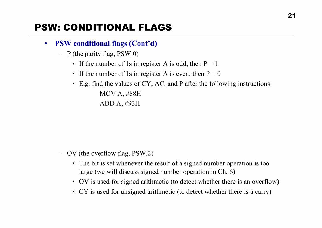
PSW: CONDITIONAL FLAGS• PSW conditional flags (Cont’d)
– P (the parity flag, PSW.0)• If the number of 1s in register A is odd, then P = 1• If the number of 1s in register A is even, then P = 0• E.g. find the values of CY, AC, and P after the following instructions
MOV A, #88HADD A, #93H
– OV (the overflow flag, PSW.2)• The bit is set whenever the result of a signed number operation is too
large (we will discuss signed number operation in Ch. 6)• OV is used for signed arithmetic (to detect whether there is an overflow)• CY is used for unsigned arithmetic (to detect whether there is a carry)
21

22
OUTLINE
• Inside 8051
• Introduction to assembly programming
• Program counter and ROM space
• PSW register and flag bits
• Register bank and stack

REGISTER BANKS: RAM SPACE• RAM space
– There are total 128 bytes of RAM in 8051 (recall: the max ROM size that can be supported by 8051 is 64 KB corresponding to 16-bit PC)
• Address range: 00H ~ • DO NOT confuse with ROM address range (ROM can only be accessed
with the PC register)– The 128 bytes are divided into three groups
• 00H – 1FH ( bytes): – register bank and stacks
• 20H – 2FH ( bytes): – bit-addressable memory
• 30H – 7FH ( bytes):– “scratch pad”– Storing data and parameters
23

REGISTER BANKS• Register banks (total 32 bytes)
– The 32 bytes are divided into 4 banks with 8 bytes in each bank• Each bank has 8 8-byte registers: R0 – R7
– When programming, e.g. “MOV A, R0”, which R0 are actually used?• Depends on the values of the RS1 (PSW.4) and RS0 (PSW.3) bits in PSW.• When 8051 powered on, RS1 = RS0 = 0 � bank 0 is used by default
24

REGISTER BANKS: EXAMPLES• Examples (demo)
– Fill out the contents of the memory between 00H – 1FH after the following operations
– 1. MOV R0, #99HMOV R7, #63H
– 2. SETB PSW.4 ; set PSW.4 to 1MOV R0, #76HCLR PSW.4SETB PSW.3MOV R5, #12H
– 3. ; the register banks can be directly accessed through its addressMOV 06H, 18H ; RAM address 06H = bank 0, R6MOV 10H, 25H ; RAM address 10H = bank 2, R0
25

REGISTER BANKS: STACK• Stack
– A section of RAM used by CPU to temporarily store information• First in last out (FILO)
– There are two 8051 instructions for stack• PUSH reg: put the byte stored in the register into the top of the stack
– E.g. MOV R6, #25HMOV R1, #12HMOV R4, #0F3HPUSH 6 ; push R6 into stackPUSH 1 ; push R1 into stackPUSH 4 ; push R4 into stack
• POP reg: pop out one byte from the top of the stack and save it in reg.– E.g. POP 3
POP 5POP 2
25H12HF3H
08H09H10H
26

REGISTER BANKS: STACK• SP register
– How does the CPU know where is the top of the stack?• The CPU has a special register, SP (statck pointer), to always point at the
top of the stack– When 8051 is powered on, SP contains a value of 07H
• The first byte pushed into stack will be at 08H (register bank 1)– Every time a PUSH is executed, SP will automatically increase by 1– Every time a POP is executed, SP will automatically decrease by 1– Demo
MOV R0, #25HMOV R1, #12HMOV R2, #0F3HPUSH 0 ; push R6 into stackPUSH 1 ; push R1 into stackPUSH 2 ; push R4 into stackPOP 3POP 4POP 5
27

REGISTER BANKS: STACK• SP register
– We can change the value of the SP register manually• MOV SP, 30H
– Conflicts between register bank 1 and stack• Register bank 1 and the default stack are using the same address (08H –
0FH)• If in a program we need to use register bank 1, we need to reallocate the
stack to somewhere else (e.g. scratch pad, 30H)– What if the stack is empty and we try to do POP (there are more POP than
PUSH)? (Demo stack)• The SP will keep decreasing• We should avoid unequal number of PUSH and POP in our program
– What if we keep PUSHing?• The SP will keep increasing until we run out of memory.
– We should be very careful with stack during programing• Plan a section of memory space for stack before programming• Do not exceed the upper limit or lower limit of in program.
28

REGISTER: STACK• Call instruction
– Whenever the “CALL” instruction is executed, CPU will use stack to temporarily store information
• SP and stack contents will change• We will discuss more details later
29