chapter 11: fundamentals of castingeng.sut.ac.th/me/box/1_54/435300/casting.pdf · chapter 11:...
TRANSCRIPT
Chapter 11:
Fundamentals of Casting
Reference : DeGarmo’s Materials and Processes in Manufacturing
ผู้ช่วยศาสตราจารย ์ เรอืโท ดร. สมญา ภูนะยา
11.1 Introduction
Products go through a series of processes before they are produced Design
Material selection
Process selection
Manufacture
Inspection and evaluation
Feedback
Materials processing is the science and technology that converts a material into a product of a desired shape in the desired quantitiy
Shape-Producing Processes
Four basic categories
Casting processes (sand casting)
Material removal processes (Machining)
Deformation processes (forging, extrusion, rolling)
Consolidation processes (Welding, Mechanical
joint)
Decisions should be made after all
alternatives and limitations are investigated
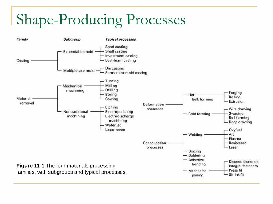
Shape-Producing Processes
Figure 11-1 The four materials processing
families, with subgroups and typical processes.
11.2 Introduction to Casting
Casting process
Material is melted
Heated to proper temperature
Treated to modify its chemical makeup
Molten material is poured into a mold
Solidifies
Casting can produce a large variety of parts
Advantages of Casting
Complex shapes
Parts can have hollow sections or cavities
Very large parts
Intricate shaping of metals that are difficult to
machine
Different mold materials can be used
Sand, metal, or ceramics
Different pouring methods
Basic Requirements of Casting Processes
Six basic steps of casting
1. Mold cavity is produced having the desired
shape and size of the part
Takes shrinkage into account
Single-use or permanent mold
2. Melting process
Provides molten material at the proper temperature
3. Pouring technique
Molten metal is poured into the mold at a proper rate to
ensure that erosion and or defects are minimized
Six Basic Steps of Casting
4. Solidification process Controlled solidification allows the product to have desired
properties
Mold should be designed so that shrinkage is controlled
5. Mold removal The casting is removed from the mold
Single-use molds are broken away from the casting
Permanent molds must be designed so that removal does not damage the part
6. Cleaning, finishing, and inspection operations Excess material along parting lines may have to be
machined
11.3 Casting Terminology
Pattern- approximate duplicate of the part to be cast
Molding material- material that is packed around the
pattern to provide the mold cavity
Flask- rigid frame that holds the molding aggregate
Cope- top half of the pattern
Drag- bottom half of the pattern
Core- sand or metal shape that is inserted into the
mold to create internal features
Casting Terminology
Mold cavity- combination of the mold material and cores
Riser-additional void in the mold that provides additional metal to compensate for shrinkage
Gating system- network of channels that delivers the molten metal to the mold
Pouring cup- portion of the gating system that controls the delivery of the metal
Sprue- vertical portion of the gating system
Runners- horizontal channels
Gates- controlled entrances
Casting Terminology
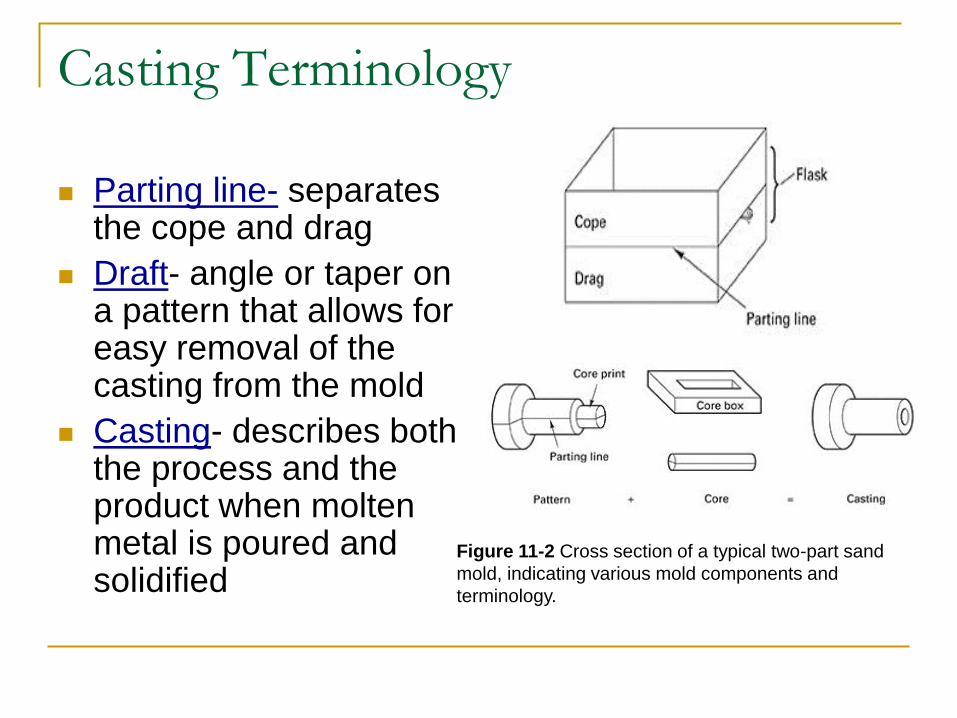
Parting line- separates the cope and drag
Draft- angle or taper on a pattern that allows for easy removal of the casting from the mold
Casting- describes both the process and the product when molten metal is poured and solidified
Figure 11-2 Cross section of a typical two-part sand
mold, indicating various mold components and
terminology.
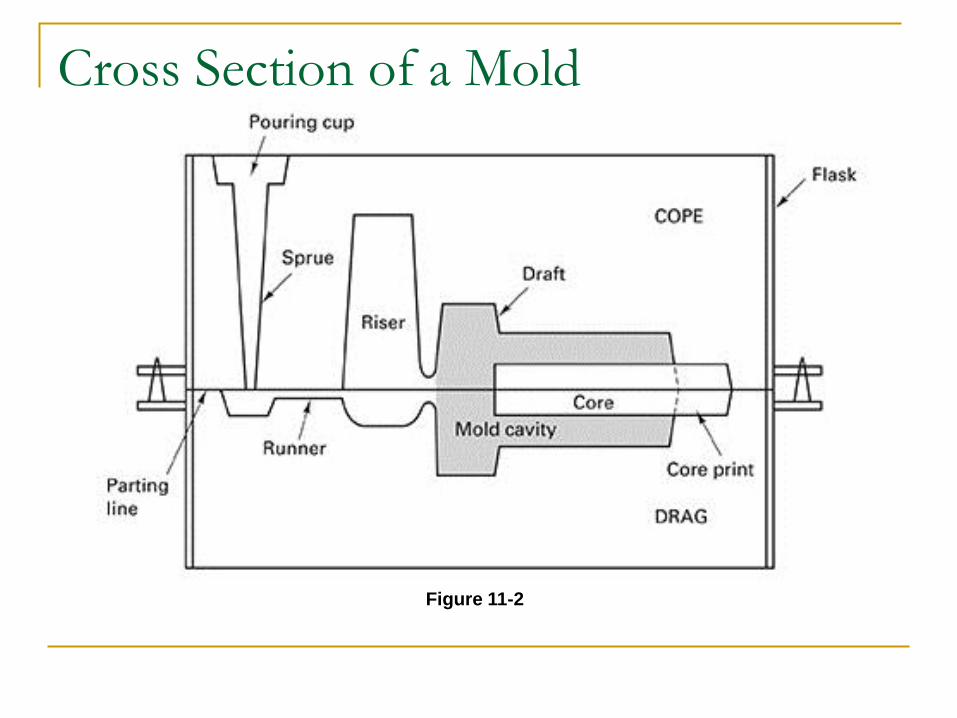
Cross Section of a Mold
Figure 11-2
11.4 The Solidification Process
Molten material is allowed to solidify into the
final shape
Casting defects occur during solidification
Gas porosity (solved by adding the vent)
Shrinkage (solved by using the riser to add the
molten metal)
Two stages of solidification
Nucleation
Growth
Nucleation
Stable particles form from the liquid metal
Occurs when there is a net release of energy from the liquid
Undercooling is the difference between the melting point and the temperature at which nucleation occurs
Each nucleation event produces a grain Nucleation is promoted (more grains) for enhanced
material properties
Inoculation or grain refinement is the process of introducing solid particles to promote nucleation
Grain Growth
Occurs as the heat of fusion is extracted from
the liquid
Direction, rate, and type of growth can be
controlled
Controlled by the way in which heat is removed
Rates of nucleation and growth control the size
and shape of the crystals
Faster cooling rates generally produce finer grain
sizes
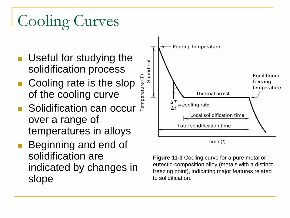
Cooling Curves
Useful for studying the solidification process
Cooling rate is the slop of the cooling curve
Solidification can occur over a range of temperatures in alloys
Beginning and end of solidification are indicated by changes in slope
Figure 11-3 Cooling curve for a pure metal or
eutectic-composition alloy (metals with a distinct
freezing point), indicating major features related
to solidification.

Cooling Curves
Figure 11-4 Phase diagram and companion cooling curve for an alloy with a freezing range. The
slope changes indicate the onset and termination of solidification.
Prediction of Solidification Time:
Chvorinov’s Rule
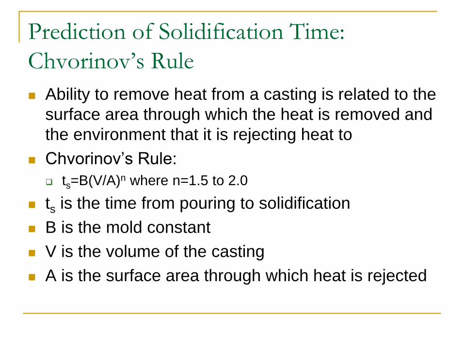
Ability to remove heat from a casting is related to the
surface area through which the heat is removed and
the environment that it is rejecting heat to
Chvorinov’s Rule:
ts=B(V/A)n where n=1.5 to 2.0
ts is the time from pouring to solidification
B is the mold constant
V is the volume of the casting
A is the surface area through which heat is rejected
Cast Structure
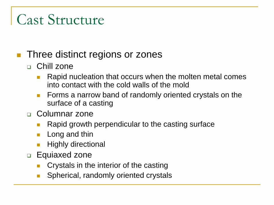
Three distinct regions or zones Chill zone
Rapid nucleation that occurs when the molten metal comes into contact with the cold walls of the mold
Forms a narrow band of randomly oriented crystals on the surface of a casting
Columnar zone
Rapid growth perpendicular to the casting surface
Long and thin
Highly directional
Equiaxed zone
Crystals in the interior of the casting
Spherical, randomly oriented crystals
Cast Structure
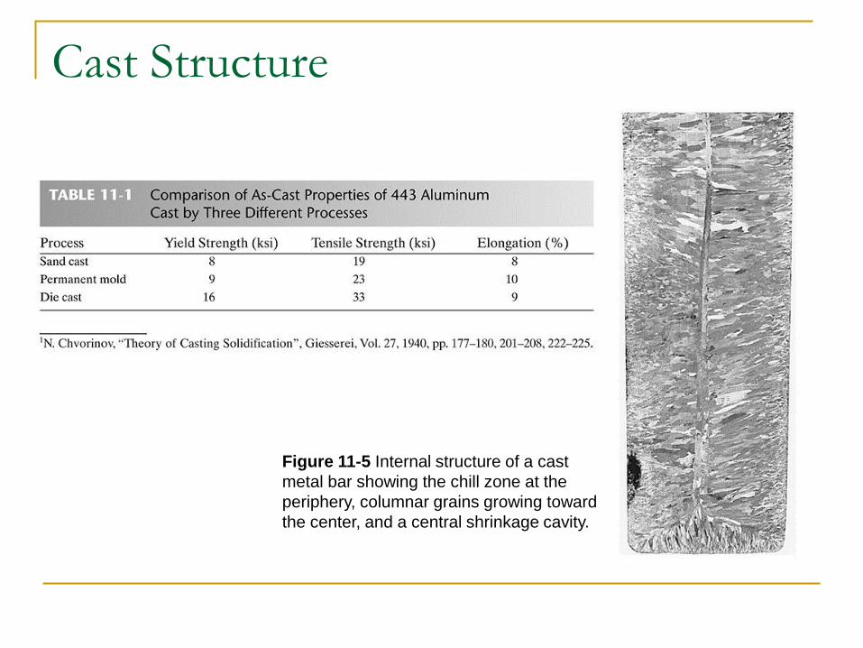
Figure 11-5 Internal structure of a cast
metal bar showing the chill zone at the
periphery, columnar grains growing toward
the center, and a central shrinkage cavity.
Molten Metal Problems
Chemical reactions can occur between molten metal and its surroundings
Reactions can lead to defects in the final castings
Metal oxides may form when molten metal reacts with oxygen
Dross or slag is the material that can be carried with the molten metal during pouring and filling of the mold Affects the surface finish, machinability, and mechanical
properties
Molten Metal Problems
Gas porosity
Gas that is not rejected from the liquid metal may be
trapped upon solidification
Several techniques to prevent gas porosity
Prevent the gas from initially dissolving in the liquid
Melting can be done in a vacuum
Melting can be done in environments with low-solubility gases
Minimize turbulence
Vacuum degassing removes the gas from the liquid before it is
poured into the castings
Gas flushing- passing inert gases or reactive gases through
the liquid metal
Fluidity and Pouring Temperature
Metal should flow into all regions of the mold cavity
and then solidify
Fluidity is the ability of a metal to flow and fill a mold
Affects the minimum section thickness, maximum length of
a thin section, fineness of detail, ability to fill mold
extremities
Dependent on the composition, freezing temperature,
freezing range, and surface tension
Most important controlling factor is pouring
temperature
The Role of the Gating System
Gating system delivers the molten metal to the mold cavity
Controls the speed of liquid metal flow and the cooling that occurs during flow
Rapid rates of filling can produce erosion of the mold cavity
Can result in the entrapment of mold material in the final casting
Cross sectional areas of the channels regulate flows
Gating Systems
Proper design minimizes turbulence
Turbulence promotes absorption of gases, oxidation, and mold erosion
Choke- smallest cross-sectional area in the gating system
Runner extensions and wells- used to catch and trap the first metal to enter the mold and prevent it from entering the mold cavity
Filters- used to trap foreign material
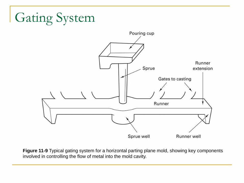
Gating System
Figure 11-9 Typical gating system for a horizontal parting plane mold, showing key components
involved in controlling the flow of metal into the mold cavity.
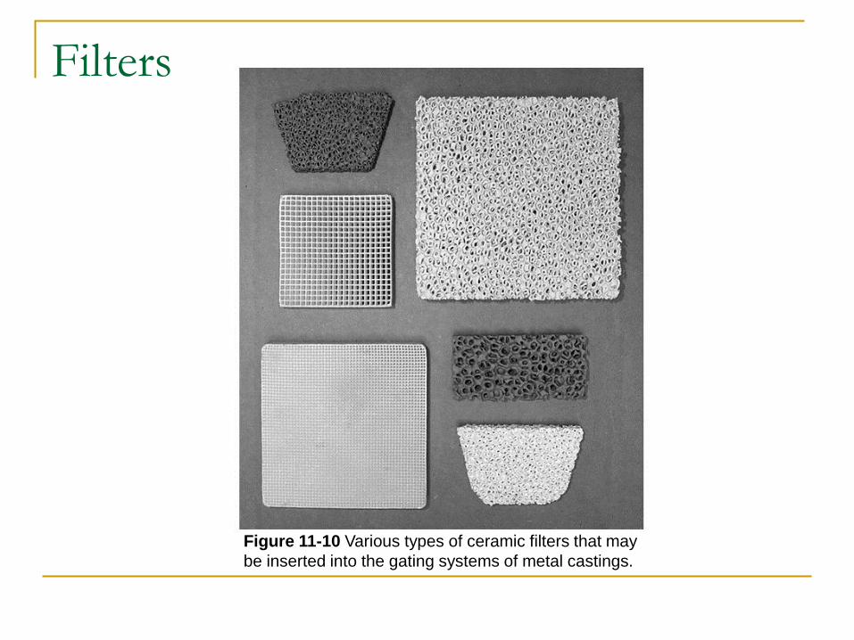
Filters
Figure 11-10 Various types of ceramic filters that may
be inserted into the gating systems of metal castings.
Solidification Shrinkage
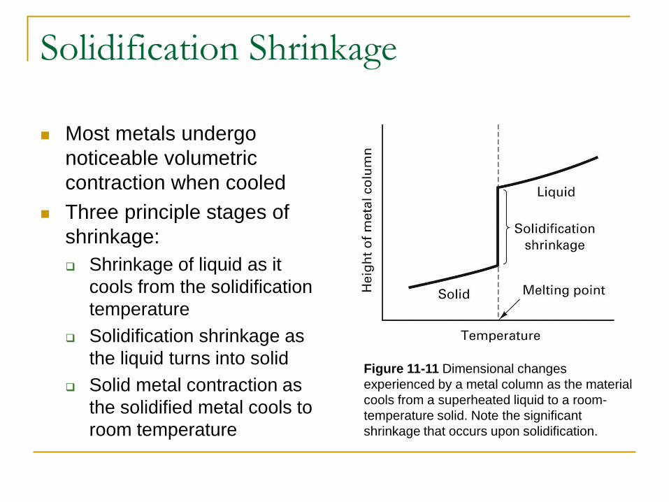
Most metals undergo
noticeable volumetric
contraction when cooled
Three principle stages of
shrinkage:
Shrinkage of liquid as it
cools from the solidification
temperature
Solidification shrinkage as
the liquid turns into solid
Solid metal contraction as
the solidified metal cools to
room temperature
Figure 11-11 Dimensional changes
experienced by a metal column as the material
cools from a superheated liquid to a room-
temperature solid. Note the significant
shrinkage that occurs upon solidification.
Solidification Shrinkage
Amount of liquid metal contraction depends on
The coefficient of thermal contraction
The amount of superheat
As the liquid metal solidifies, the atomic structure
normally becomes more efficient and significant
amounts of shrinkage can occur
Cavities and voids can be prevented by designing
the casting to have directional solidification
Hot tears can occur when there is significant tensile
stress on the surface of the casting material
Risers and Riser Design
Risers are reservoirs of liquid metal that feed extra
metal to the mold to compensate for shrinkage
Risers are designed to conserve metal
Located so that directional solidification occurs from
the extremities of the mold toward the riser
Should feed directly to the thickest regions of the
casting
Blind riser- contained entirely within the mold cavity
Live riser- receive the last hot metal that enters the
mold
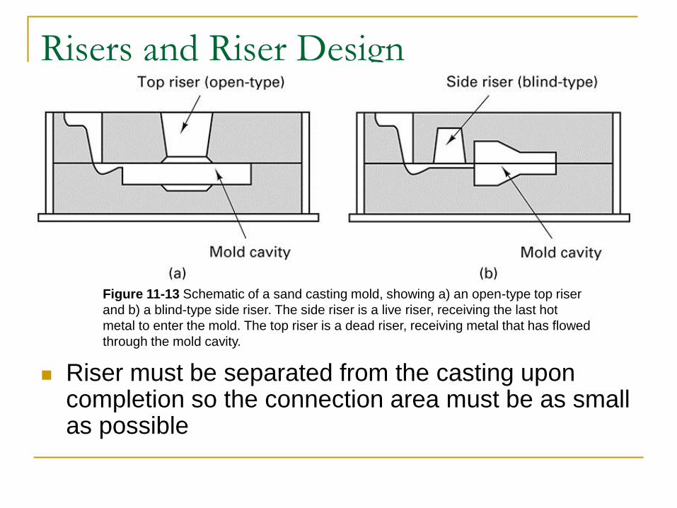
Risers and Riser Design
Riser must be separated from the casting upon completion so the connection area must be as small as possible
Figure 11-13 Schematic of a sand casting mold, showing a) an open-type top riser
and b) a blind-type side riser. The side riser is a live riser, receiving the last hot
metal to enter the mold. The top riser is a dead riser, receiving metal that has flowed
through the mold cavity.

Riser Aids
Riser’s performance may be enhanced by speeding
the solidification of the casting (chills) or slowing
down the solidification (sleeves or toppings)
External chills
Masses of high-heat capacity material placed in the mold
Absorb heat and accelerate cooling in specific regions
Internal chills
Pieces of metal that are placed in the mold cavity and
promote rapid solidification
Ultimately become part of the cast part

Go to ch 12
11.5 Patterns
Two basic categories for casting processes
Expendable mold processes
Permanent mold processes
Patterns are made from wood, metal, foam, or plastic
Dimensional modification are incorporated into the design (allowances)
Shrinkage allowance is the most important
Pattern must be slightly larger than the desired part
Dimensional Allowances
Typical allowances Cast iron 0.8-1.0%
Steel 1.5-2.0%
Aluminum 1.0-1.3%
Magnesium 1.0-1.3%
Brass 1.5%
Shrinkage allowances are incorporated into the pattern using shrink rules
Thermal contraction might not be the only factor for determining pattern size
Surface finishing operations (machining, etc.) should be taken into consideration
Pattern Removal
Parting lines are the preferred method
Damage can be done to the casting at corners or parting surfaces if tapers or draft angles are not used in the pattern
Factors that influence the needed draft Size and shape of pattern
Depth of mold cavity
Method used to withdraw pattern
Pattern material
Mold material
Molding procedure
Design Considerations
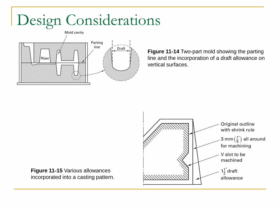
Figure 11-15 Various allowances
incorporated into a casting pattern.
Figure 11-14 Two-part mold showing the parting
line and the incorporation of a draft allowance on
vertical surfaces.
11.6 Design Considerations in Castings
Location and orientation of the parting line is
important to castings
Parting line can affect:
Number of cores
Method of supporting cores
Use of effective and economical gating
Weight of the final casting
Final dimensional accuracy
Ease of molding
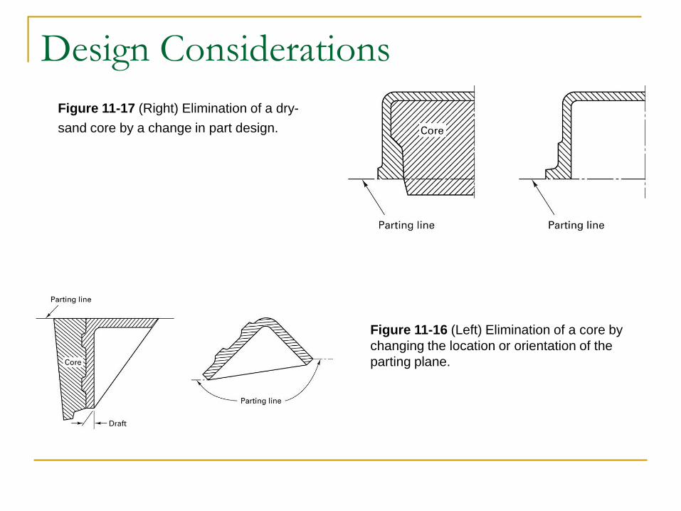
Design Considerations
Figure 11-16 (Left) Elimination of a core by
changing the location or orientation of the
parting plane.
Figure 11-17 (Right) Elimination of a dry-
sand core by a change in part design.
Design Considerations
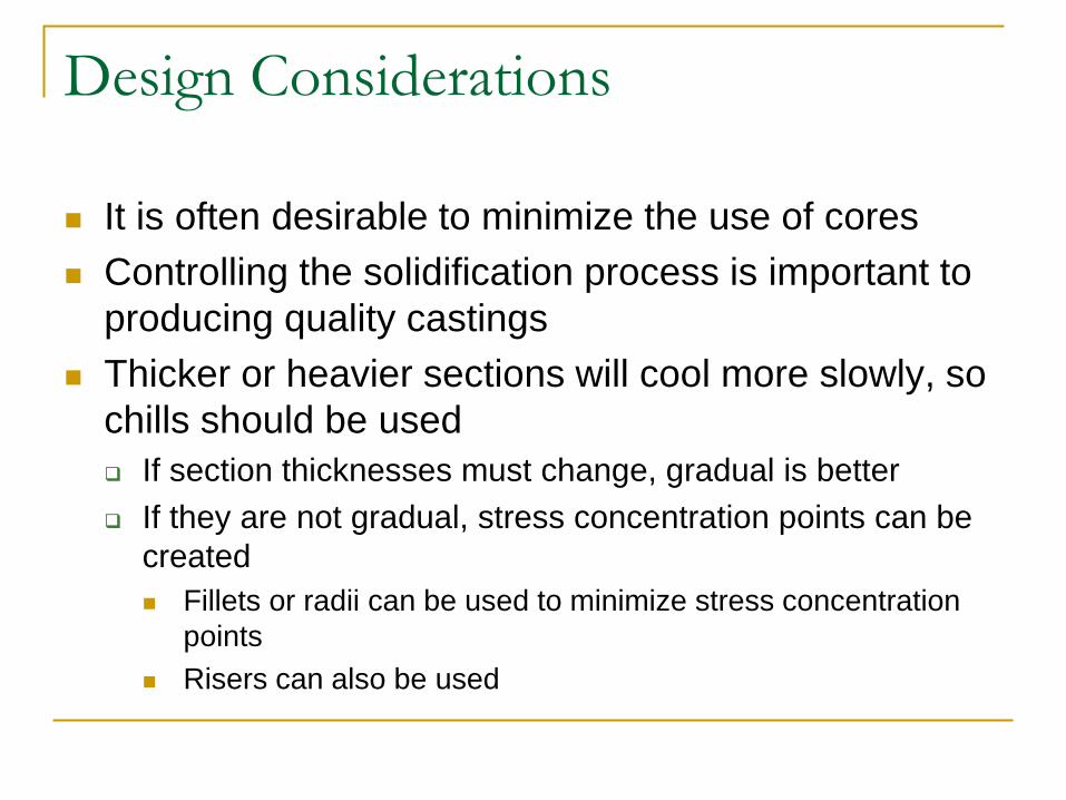
It is often desirable to minimize the use of cores
Controlling the solidification process is important to
producing quality castings
Thicker or heavier sections will cool more slowly, so
chills should be used
If section thicknesses must change, gradual is better
If they are not gradual, stress concentration points can be
created
Fillets or radii can be used to minimize stress concentration
points
Risers can also be used

Parting Line and Drafts
Figure 11-18 (Top left) Design where the location of the parting plane is specified by the
draft. (Top right) Part with draft unspecified. (Bottom) Various options to produce the top-
right part, including a no-draft design.
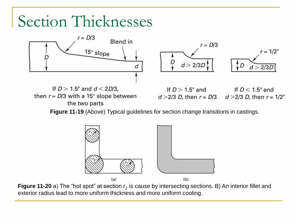
Section Thicknesses
Figure 11-19 (Above) Typical guidelines for section change transitions in castings.
Figure 11-20 a) The “hot spot” at section r2 is cause by intersecting sections. B) An interior fillet and
exterior radius lead to more uniform thickness and more uniform cooling.

Design Modifications
Hot spots are areas of the material that cool more
slowly than other locations
Function of part geometry
Localized shrinkage may occur
Figure 11-21 Hot spots often result from intersecting sections of various thickness.
Design Modifications
Parts that have ribs may experience cracking
due to contraction
Ribs may be staggered to prevent cracking
An excess of material may appear around the
parting line
The parting line may be moved to improve
appearance
Thin-walled castings should be designed with
extra caution to prevent cracking
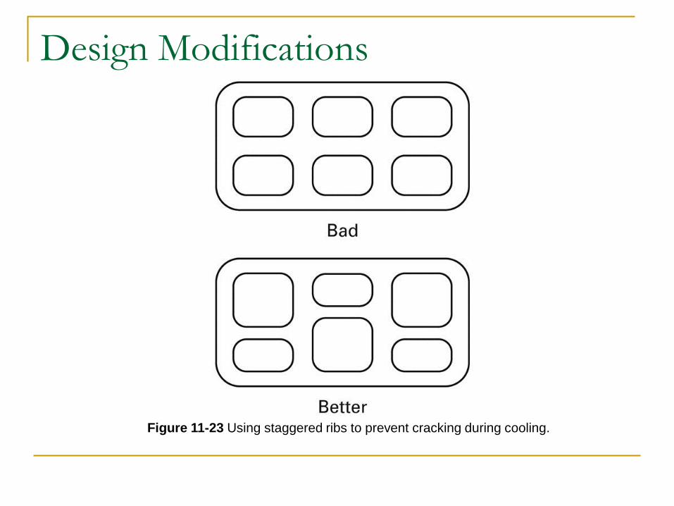
Design Modifications
Figure 11-23 Using staggered ribs to prevent cracking during cooling.
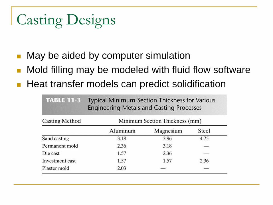
Casting Designs
May be aided by computer simulation
Mold filling may be modeled with fluid flow software
Heat transfer models can predict solidification

11.7 The Casting Industry
14 million pounds of castings are produced every year
The most common materials cast are gray iron, ductile iron, aluminum alloys, and copper alloys
35% of the market is in automotive and light truck manufacturing
Castings are used in applications ranging from agriculture to railroad equipment and heating and refrigeration

Summary
A successful casting requires that every aspect of the process be examined
Every aspect from the desired grain structure to the desired finish of the product should be considered during design stages
Efforts should be made to minimize cracking and defects
There are a variety of processes to improve castings and they should all be considered during the design phase