chapter 12 secondary-storage systems - 國立中興大學 · chapter 12 secondary-storage systems....
TRANSCRIPT

Silberschatz, Galvin and Gagne ©2005Operating System Concepts –7th Edition, Jan 14, 2005
Chapter 12Chapter 12SecondarySecondary--Storage SystemsStorage Systems
NCHU System & Network LabNCHU System & Network Lab
OutlineOutline
•Overview of Mass Storage Structure•Disk Structure•Disk Attachment•Disk Scheduling•Disk Management•Swap-Space Management•RAID Structure•Stable-Storage Implementation•Tertiary Storage Devices
Silberschatz, Galvin and Gagne ©2005Operating System Concepts –7th Edition, Jan 14, 2005
12.112.1 Overview of Mass StorageOverview of Mass StorageStructureStructure
NCHU System & Network LabNCHU System & Network Lab
Overview of Mass Storage StructureOverview of Mass Storage Structure
•Magnetic disks provide bulk of secondary storage of moderncomputers–Transfer rate is rate at which data flow between drive and computer–Positioning time (random-access time) = seek time + rotational
latency•Seek time: the time to move disk arm to desired cylinder•Rotational latency : the time for desired sector to rotate under the disk
head ()–Head crash results from disk head making contact with the disk
surface•That’s bad
•Drive attached to computer via I/O bus–Busses vary, including EIDE, ATA, SATA, USB, Fibre Channel,
SCSI–Host controller in computer uses bus to talk to disk controller built
into drive or storage array

NCHU System & Network LabNCHU System & Network Lab
MovingMoving--Head DiskHead Disk MachanismMachanism

NCHU System & Network LabNCHU System & Network Lab
Overview of Mass Storage StructureOverview of Mass Storage Structure(Cont.)(Cont.)
•Magnetic tape–Was early secondary-storage medium–Relatively permanent and holds large quantities of data–Access time slow–Random access ~1000 times slower than disk–Mainly used for backup, storage of infrequently-used data,
transfer medium between systems–Kept in spool and wound or rewound past read-write head–Once data under head, transfer rates comparable to disk–20-200GB typical storage
Silberschatz, Galvin and Gagne ©2005Operating System Concepts –7th Edition, Jan 14, 2005
12.212.2 Disk StructureDisk Structure

NCHU System & Network LabNCHU System & Network Lab
Disk StructureDisk Structure
•Disk drives are addressed as large 1-dimensional arrays oflogical blocks–The logical block is the smallest unit of transfer.
•The 1-dimensional array of logical blocks is mapped into thesectors of the disk sequentially.–Sector 0 is the first sector of the first track on the outermost cylinder.
•Mapping proceeds in order through that track•Then the rest of the tracks in that cylinder•And then through the rest of the cylinders from outermost to innermost.
–Mapping proceeds (Cylinder, Track, Sector)– In practice, not always possible
•Defective Sectors•# of tracks per cylinders is not a constant

Silberschatz, Galvin and Gagne ©2005Operating System Concepts –7th Edition, Jan 14, 2005
12.3 Disk Attachment12.3 Disk Attachment

NCHU System & Network LabNCHU System & Network Lab
Disk AttachmentDisk Attachment
•Disks may be attached one of two ways:–Host attached storage via an I/O port
•I/O bus architecture: IDE or ATA in PC•Sophisticated I/O architecture: SCSI and FC (Fiber Channel)
–Network attached storage via a network connection•NFS (Unix) and CIFS (Windows) are common protocols•Implemented via remote procedure calls (RPCs) between host and
storage•New iSCSI protocol uses IP network to carry the SCSI protocol

NCHU System & Network LabNCHU System & Network Lab
NetworkNetwork--Attached StorageAttached Storage

NCHU System & Network LabNCHU System & Network Lab
StorageStorage--Area NetworkArea Network
•Problem of NAS: storage I/O operations consumebandwidth on the data network–Communications between server and clients competes with
communication among servers and NAS
•Sol: storage-area network–A private network (using storage protocols rather than
network protocols) among servers and storage units–Separate from LAN or WAN connecting clients and servers–Multiple hosts and multiple storage arrays can attach to the
same SAN - flexible

NCHU System & Network LabNCHU System & Network Lab
StorageStorage--Area NetworkArea Network
Silberschatz, Galvin and Gagne ©2005Operating System Concepts –7th Edition, Jan 14, 2005
12.4 Disk Scheduling12.4 Disk Scheduling

NCHU System & Network LabNCHU System & Network Lab
Disk SchedulingDisk Scheduling•OS is responsible for using hardware efficiently
–For the disk drives fast access time and disk bandwidth.•Access time has two major components
–Seek time is the time for the disk are to move the heads to the cylindercontaining the desired sector.•Seek time seek distance•Minimize seek time
–Rotational latency is the additional time waiting for the disk to rotatethe desired sector to the disk head.•Difficult for OS•OS do not know the physical location of logical blocks
•Disk bandwidth =– (Total number of bytes transferred) / Total time between the first
request for service and the completion of the last transfer.

NCHU System & Network LabNCHU System & Network Lab
Disk Scheduling (Cont.)Disk Scheduling (Cont.)
•Several algorithms exist to schedule theservicing of disk I/O requests.
•We illustrate them with a request queue (0-199).–98, 183, 37, 122, 14, 124, 65, 67–Head pointer 53

NCHU System & Network LabNCHU System & Network Lab
FCFSFCFSIllustration shows total head movement of 640 cylinders.
NCHU System & Network LabNCHU System & Network Lab
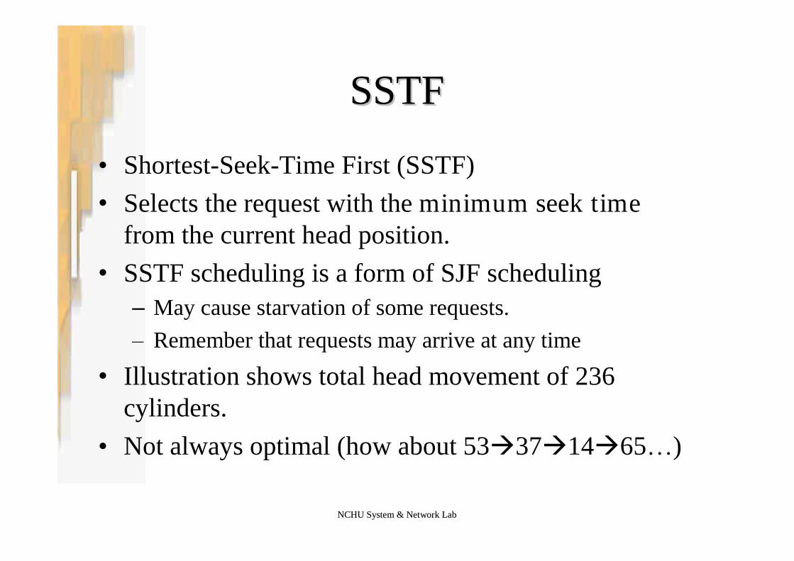
SSTFSSTF
•Shortest-Seek-Time First (SSTF)•Selects the request with the minimum seek time
from the current head position.•SSTF scheduling is a form of SJF scheduling
–May cause starvation of some requests.–Remember that requests may arrive at any time
•Illustration shows total head movement of 236cylinders.
•Not always optimal (how about 53371465…)

NCHU System & Network LabNCHU System & Network Lab
SSTF (Cont.)SSTF (Cont.)
NCHU System & Network LabNCHU System & Network Lab
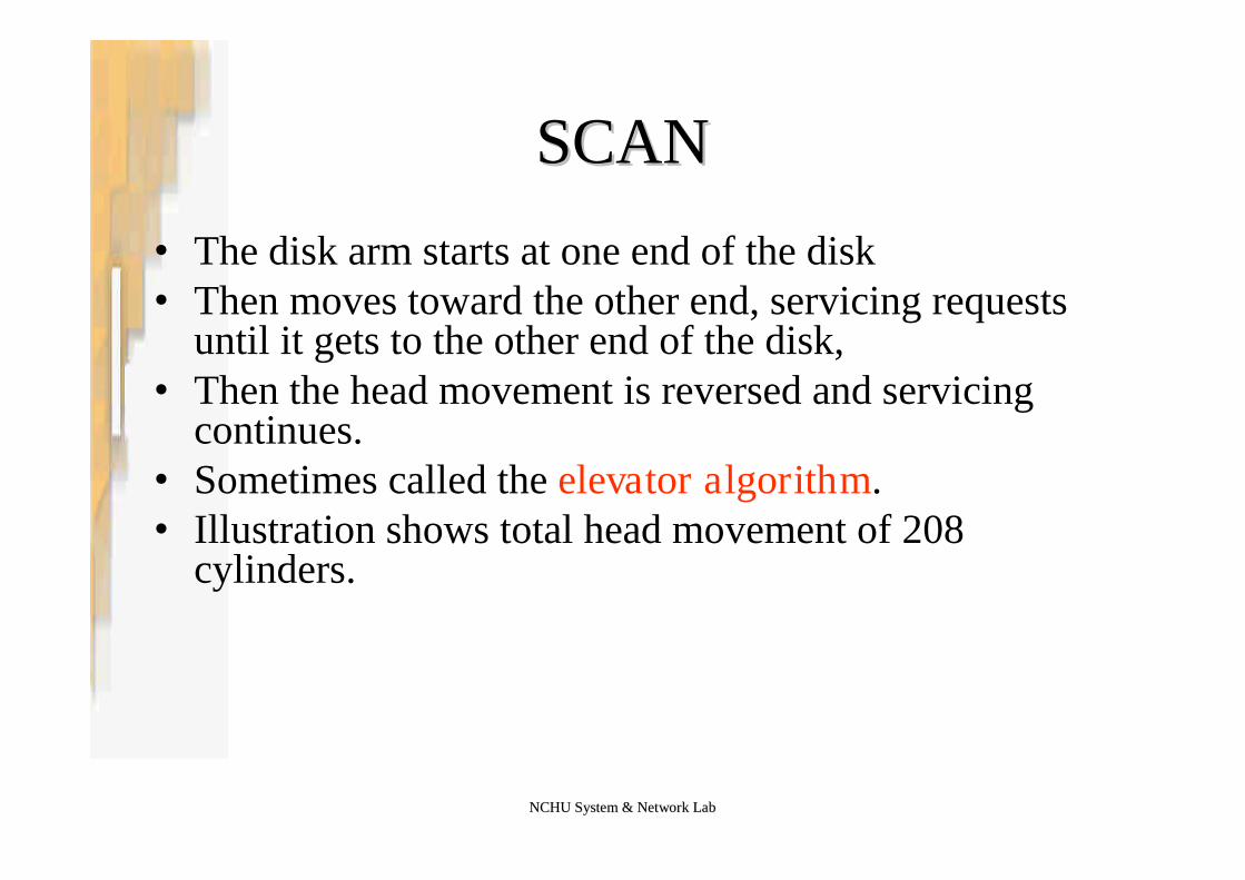
SCANSCAN
•The disk arm starts at one end of the disk•Then moves toward the other end, servicing requests
until it gets to the other end of the disk,•Then the head movement is reversed and servicing
continues.•Sometimes called the elevator algorithm.•Illustration shows total head movement of 208
cylinders.

NCHU System & Network LabNCHU System & Network Lab
SCAN (Cont.)SCAN (Cont.)

NCHU System & Network LabNCHU System & Network Lab
CC--SCANSCAN
•Provides a more uniform wait time than SCAN.•The head moves from one end of the disk to the
other, servicing requests as it goes.•When it reaches the other end, however,
–It immediately returns to the beginning of the disk,without servicing any requests on the return trip.
•Treats the cylinders as a circular list that wrapsaround from the last cylinder to the first one.

NCHU System & Network LabNCHU System & Network Lab
CC--SCAN (Cont.)SCAN (Cont.)
NCHU System & Network LabNCHU System & Network Lab
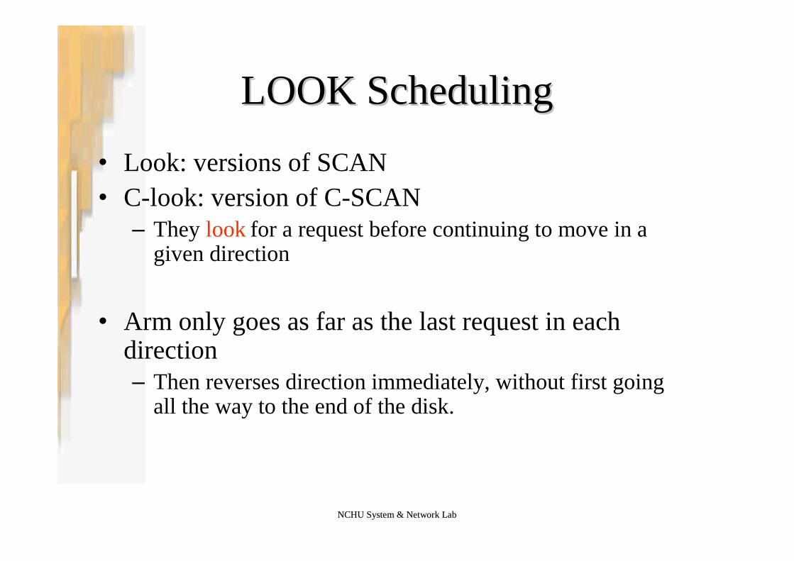
LOOK SchedulingLOOK Scheduling
•Look: versions of SCAN•C-look: version of C-SCAN
–They look for a request before continuing to move in agiven direction
•Arm only goes as far as the last request in eachdirection–Then reverses direction immediately, without first going
all the way to the end of the disk.

NCHU System & Network LabNCHU System & Network Lab
CC--LOOK (Cont.)LOOK (Cont.)

NCHU System & Network LabNCHU System & Network Lab
Selecting a DiskSelecting a Disk--Scheduling AlgorithmScheduling Algorithm
• SSTF is common and has a natural appeal– Increase performance over FCFS
• SCAN and C-SCAN perform better for systems that place a heavy load onthe disk.– Less likely to cause a starvation problem
• Performance depends on the number and types of requests.• Requests for disk service can be influenced by the file-allocation method.
– Contiguously allocated - limited head movement– Linked allocation scheme –greater head movement
• The disk-scheduling algorithm should be written as a separate module ofthe operating system– Allowing it to be replaced with a different algorithm if necessary.– Either SSTF or LOOK is a reasonable choice for the default algorithm.
• Implement disk scheduling on Disk Controller– Can further reduce the rotational latency

Silberschatz, Galvin and Gagne ©2005Operating System Concepts –7th Edition, Jan 14, 2005
12.5 Disk Management12.5 Disk Management
NCHU System & Network LabNCHU System & Network Lab
Disk ManagementDisk Management
•Disk formatting–Low-level formatting, or physical formatting–Dividing a disk into sectors that the disk controller
can read and write.
•Boot Block•Bad Block
NCHU System & Network LabNCHU System & Network Lab
Disk FormattingDisk Formatting
•Low-level formatting, or physical formatting•Divide a disk into sectors that the controller can read and write
–A new disk is a blank state–Fill each sector with a special data structure: header –data –trailer
•Header and Trailer contains information used by diskcontroller–A sector number and an error-correcting code (ECC)
•When the controller writes a sector of data–ECC is updated with a value calculated from all the bytes in the data
area
•When the sector is read, ECC is recalculated and is comparedwith the stored value verify the data is correct
NCHU System & Network LabNCHU System & Network Lab
Disk PartitionDisk Partition
•To use a disk to hold files, OS still needs to record itsown data structures on the disk
•Partition the disk into one or more groups ofcylinders–Each partition can be treated as a separate disk
•Logical formatting or “making a file system”–Store the initial file-system data structure onto the disk…
•Maps of free and allocated space (FAT or inode)•An initial empty directory

NCHU System & Network LabNCHU System & Network Lab
Raw DiskRaw Disk
•Use a disk partition as a large sequential array oflogical blocks–Without any file-system data structures
•This array is called raw disk–The I/Os to the array is called raw I/O
•Example–swap space
•Raw I/O bypasses all the file-system services–Such as the buffer cache, file locking, pre-fetching, space
allocation, file names, and directories
NCHU System & Network LabNCHU System & Network Lab
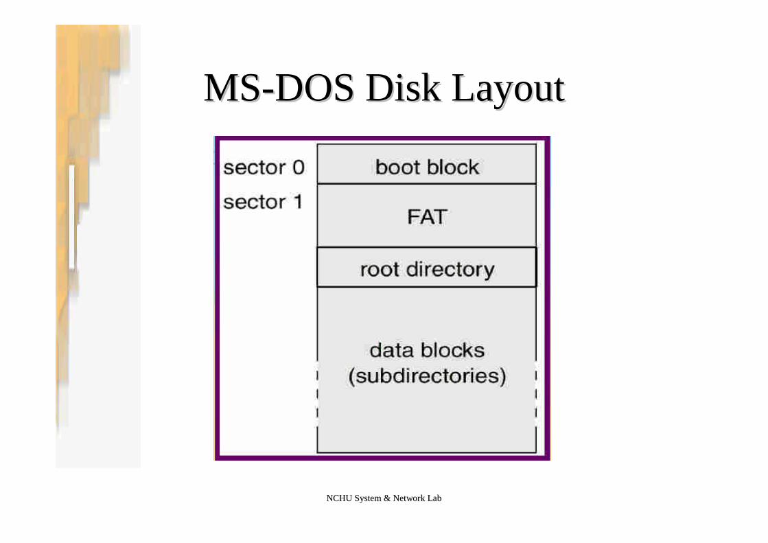
Boot BlockBoot Block
•Bootstrap program initializes system.–Initialize CPU registers, device controllers, main memory–Start OS
•In PC, two-step approaches–A tiny bootstrap program is stored in ROM.
•Bring in a full bootstrap program from disk, a bootstrap loader
–Full bootstrap program.•Stored in boot block: at a fixed location on the disk•Load the OS and start the OS•This disk is called boot disk or system disk
NCHU System & Network LabNCHU System & Network Lab
MSMS--DOS Disk LayoutDOS Disk Layout
NCHU System & Network LabNCHU System & Network Lab
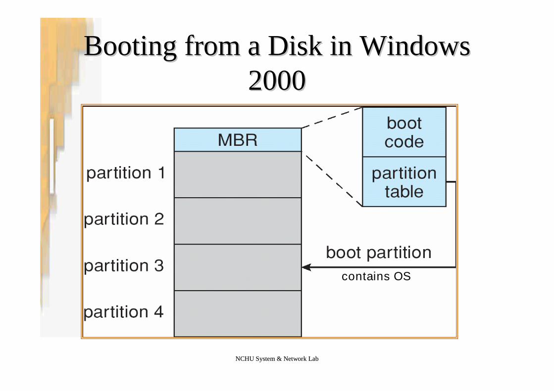
Booting from a Disk in WindowsBooting from a Disk in Windows20002000
contains OS

NCHU System & Network LabNCHU System & Network Lab
Bad BlocksBad Blocks
•IDE–MS-DOS format : performs logical formating
•Scan the disk to find bad blocks•Write a special value into the corresponding FAT entry for
bad blocks
–MS-DOS chkdsk : if blocks go bad during operations•Search and lock bad blocks

NCHU System & Network LabNCHU System & Network Lab
Bad Blocks (Cont.)Bad Blocks (Cont.)
•SCSI–Controller maintains a list of bad blocks on the disk–Low-level formatting will set aside spare sectors
•OS don’t know
–Sector sparing (or forwarding):•Controller replaces each bad sector logically with one of the spare
sectors•Invalidate optimization by OS’s disk scheduling
–Sol: Each cylinder has a few spare sectors
•Another technique: sector slipping–Ex. 17 defective, spare follows sector 202
•Spare 202 201…18 17
Silberschatz, Galvin and Gagne ©2005Operating System Concepts –7th Edition, Jan 14, 2005
12.6 Swap12.6 Swap--Space ManagementSpace Management
NCHU System & Network LabNCHU System & Network Lab
SwapSwap--Space ManagementSpace Management
•Swap-space — virtual memory uses disk space as anextension of main memory.
•Main goal for the design and implementation of swap space isto provide the best throughput for VM system
•Swap-space use–Swapping –use swap space to hold entire process image–Paging –store pages that have been pushed out of memory
•Some OS may support multiple swap-space–Put on separate disks to balance the load
•Better to overestimate than underestimate– If out of swap-space, some processes must be aborted or system
crashed

NCHU System & Network LabNCHU System & Network Lab
SwapSwap--Space LocationSpace Location
•Swap-space can be carved out of the normal file system, or in aseparate disk partition.
•A large file within the file system: simple but inefficient–Navigating the directory structure and the disk-allocation data
structure takes time and potentially extra disk accesses–External fragmentation can greatly increase swapping times by forcing
multiple seeks during reading or writing of a process image– Improvement
•Caching block location information in main memory•Contiguous allocation for the swap file
–But, the cost of traversing FS data structure still remains

NCHU System & Network LabNCHU System & Network Lab
SwapSwap--Space LocationSpace Location
•In a separate partition: raw partition–Create a swap space during disk partitioning–A separate swap-space storage manager is used to
allocate and de-allocate blocks–Use algorithms optimized for speed, rather than
storage efficiency–Internal fragment may increase
•Linux supports both approaches

NCHU System & Network LabNCHU System & Network Lab
SwapSwap--space Management: Examplespace Management: Example
•Solaris 1–Text-segment pages are brought in from the file system and
are thrown away if selected for paged out•More efficient to re-read from FS than write it to the swap space
–Swap space: only used as a backing store for pages ofanonymous memory•Stack, heap, and uninitialized data
•Solaris 2–Allocates swap space only when a page is forced out of
physical memory•Not when the virtual memory page is first created.

Silberschatz, Galvin and Gagne ©2005Operating System Concepts –7th Edition, Jan 14, 2005
12.6 RAID Structure12.6 RAID Structure

NCHU System & Network LabNCHU System & Network Lab
RAID StructureRAID Structure
•RAID–Redundant Arrays of Inexpensive Disks–Redundant Arrays of Independent Disks
•RAID: use of multiple disks workingcooperatively–Improve the performance (data rate)–Improve reliability
•RAID is arranged into six different levels.
NCHU System & Network LabNCHU System & Network Lab
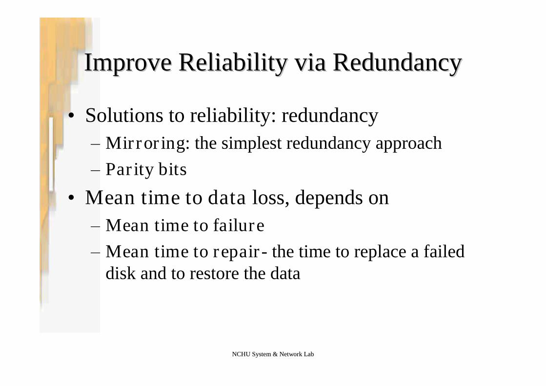
Improve Reliability via RedundancyImprove Reliability via Redundancy
•Solutions to reliability: redundancy–Mirroring: the simplest redundancy approach–Parity bits
•Mean time to data loss, depends on–Mean time to failure–Mean time to repair- the time to replace a failed
disk and to restore the data
NCHU System & Network LabNCHU System & Network Lab
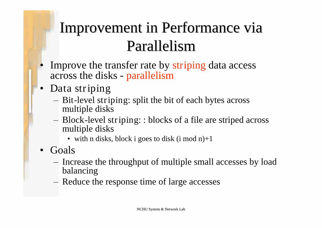
Improvement in Performance viaImprovement in Performance viaParallelismParallelism
•Improve the transfer rate by striping data accessacross the disks - parallelism
•Data striping–Bit-level striping: split the bit of each bytes across
multiple disks–Block-level striping: : blocks of a file are striped across
multiple disks•with n disks, block i goes to disk (i mod n)+1
•Goals–Increase the throughput of multiple small accesses by load
balancing–Reduce the response time of large accesses
NCHU System & Network LabNCHU System & Network Lab
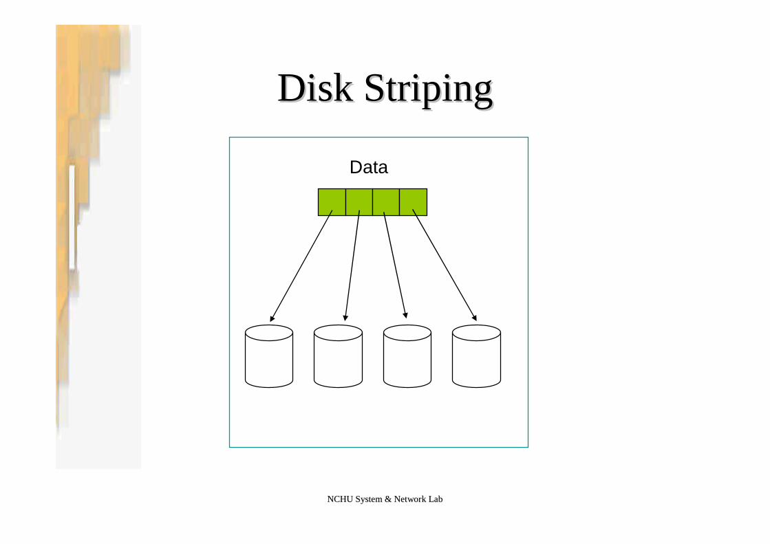
Disk StripingDisk Striping
Data

NCHU System & Network LabNCHU System & Network Lab
RAID LevelsRAID Levels
NCHU System & Network LabNCHU System & Network Lab
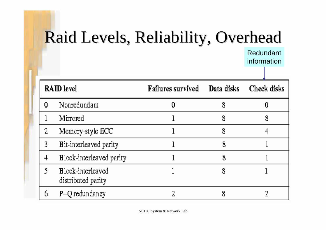
Raid Levels, Reliability, OverheadRaid Levels, Reliability, OverheadRedundantinformation
NCHU System & Network LabNCHU System & Network Lab
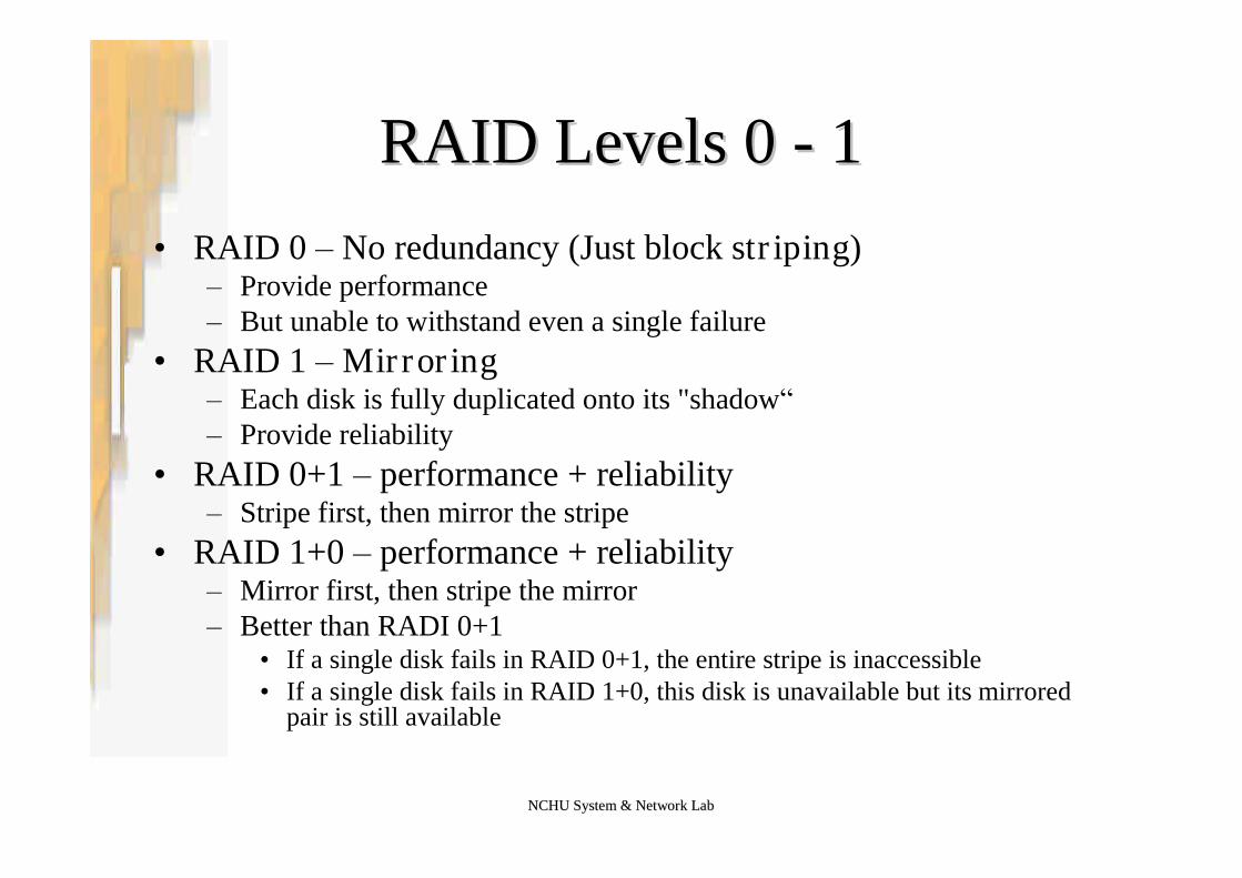
RAID Levels 0RAID Levels 0 -- 11•RAID 0 –No redundancy (Just block striping)
–Provide performance–But unable to withstand even a single failure
•RAID 1 –Mirroring–Each disk is fully duplicated onto its "shadow“–Provide reliability
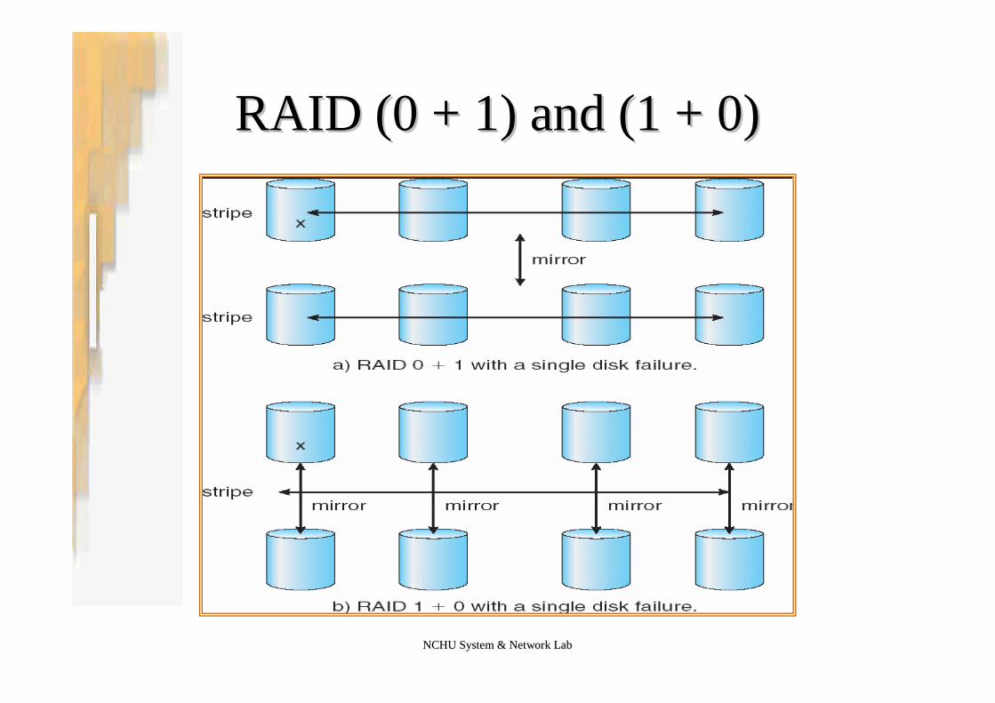
•RAID 0+1 –performance + reliability–Stripe first, then mirror the stripe
•RAID 1+0 –performance + reliability–Mirror first, then stripe the mirror–Better than RADI 0+1
•If a single disk fails in RAID 0+1, the entire stripe is inaccessible•If a single disk fails in RAID 1+0, this disk is unavailable but its mirrored
pair is still available
NCHU System & Network LabNCHU System & Network Lab
RAID (0 + 1) and (1 + 0)RAID (0 + 1) and (1 + 0)
NCHU System & Network LabNCHU System & Network Lab
RAID Levels 2 & 3RAID Levels 2 & 3
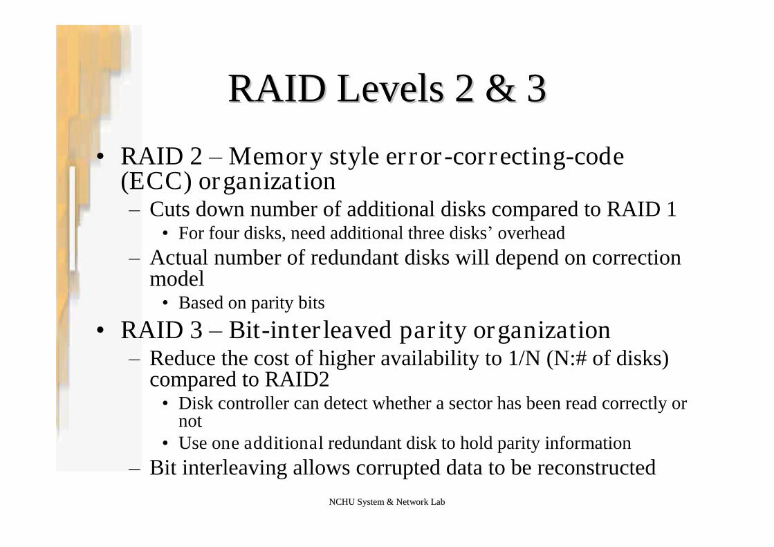
•RAID 2 –Memory style error-correcting-code(ECC) organization–Cuts down number of additional disks compared to RAID 1
•For four disks, need additional three disks’overhead–Actual number of redundant disks will depend on correction
model•Based on parity bits
•RAID 3 –Bit-interleaved parity organization–Reduce the cost of higher availability to 1/N (N:# of disks)
compared to RAID2•Disk controller can detect whether a sector has been read correctly or
not•Use one additional redundant disk to hold parity information
–Bit interleaving allows corrupted data to be reconstructed

NCHU System & Network LabNCHU System & Network Lab
RAID Levels 4 & 5 & 6RAID Levels 4 & 5 & 6
•RAID 4 –Block-interleaved parity organization–Similar idea as RAID 3 but sum is on a per block basis–Hence only the parity disk and the target disk need be accessed–Problem still with concurrent writes since parity disk bottlenecks
•RAID 5 –Block-interleaved distributed parity organization–Parity blocks are interleaved and distributed on all disks
•Parity blocks no longer reside on same disk–Probability of write collisions to a single parity drive are reduced–Hence higher performance in the consecutive write situation–Most common parity RAID system
•RAID 6 –P+Q redundancy scheme–Similar to RAID 5, but stores extra redundant information to guard
against multiple disk failures

NCHU System & Network LabNCHU System & Network Lab
Raid 4 & 5 IllustrationRaid 4 & 5 Illustration
RAID 4 RAID 5
Silberschatz, Galvin and Gagne ©2005Operating System Concepts –7th Edition, Jan 14, 2005
112.82.8StableStable--Storage ImplementationStorage Implementation

NCHU System & Network LabNCHU System & Network Lab
OverviewOverview
•Information residing in stable storage is neverlost
•To implement stable storage:–Replicate information on more than one
nonvolatile storage media with independent failuremodes
–Update information in a controlled manner•Ensure that we can recover the stable data after any
failure during data transfer or recovery
NCHU System & Network LabNCHU System & Network Lab
Disk Write ResultDisk Write Result
•Disk write results–Successful Completion–Partial Failure
•A failure occurred in the midst of transfer•Some of the sectors were written with the new data•The sector being written during the failure may have
been corrupted–Total Failure
•Failure occurred before the disk write started•The previous data value on the disk remain intact

NCHU System & Network LabNCHU System & Network Lab
SolutionsSolutions
•First, system must maintain at least twophysical blocks for each logical block
•A write operation is executed as follows–Write the information onto the first physical block–When the first write completes successfully
•Write the same information onto the second physicalblock
–Declare the operation complete only after thesecond write completes successfully
NCHU System & Network LabNCHU System & Network Lab
Failure Detection and RecoveryFailure Detection and Recovery
•Each pair of physical blocks is examined–If both are the same and no detectable error exists
•OK
–If one contains a detectable error•We replace its contents with the value of the other block
–If both contain no detectable error but they differ in content•We replace the content of the first block with the value of the
second
•Ensure that a write to stable storage either succeedscompletely or results in no change

Silberschatz, Galvin and Gagne ©2005Operating System Concepts –7th Edition, Jan 14, 2005
112.92.9TertiaryTertiary--Storage StructureStorage Structure

NCHU System & Network LabNCHU System & Network Lab
Tertiary Storage DevicesTertiary Storage Devices
•Low cost is the defining characteristic oftertiary storage.
•Generally, tertiary storage is built usingremovable media
•Examples of removable media:–Floppy disks and CD-ROMs–Other types are available.
NCHU System & Network LabNCHU System & Network Lab
Removable DisksRemovable Disks
•Floppy disk —–Thin flexible disk coated with magnetic material,
enclosed in a protective plastic case.–Most floppies hold about 1 MB
•Removable disk–Similar technology of floppy disk but holds more
than 1 GB.–Can be nearly as fast as hard disks
•But they are at a greater risk of damage from exposure.
NCHU System & Network LabNCHU System & Network Lab
Removable Disks (Cont.)Removable Disks (Cont.)
•Magneto-optic disk–Records data on a rigid platter coated with magnetic material.–Laser heat is used to amplify a large, weak magnetic field to record a
bit.–Laser light is also used to read data (Kerr effect).–Resistant to head crashes.
•The magneto-optic head flies much farther from the disk surface than amagnetic disk head
•The magnetic material is covered with a protective layer of plastic or glass;
•Optical disks–Do not use magnetism–Employ special materials that are altered by laser light.

NCHU System & Network LabNCHU System & Network Lab
Removable Disks (Cont.)Removable Disks (Cont.)
•Previous disk are read-write disks–The data on can be modified over and over.
•WORM (Write Once, Read Many Times) disks–Can be written only once.–Thin aluminum film sandwiched between two glass or plastic platters.–To write a bit, the drive uses a laser light to burn a small hole through
the aluminum•Information can be destroyed by not altered.
–Very durable and reliable.–Example: recordable CD-R and DVD-R
•Read Only disks–Come from the factory with the data pre-recorded.–Example: CD-ROM and DVD,

NCHU System & Network LabNCHU System & Network Lab
TapesTapes•Compared to a disk, a tape is less expensive and holds more
data–But random access is much slower.
•Tape is an economical medium for purposes that do notrequire fast random access–Backup copies of disk data, holding huge volumes of data.
•Large tape installations typically use robotic tape changers thatmove tapes between tape drives and storage slots in a tapelibrary.–Also called near-line storage
•A disk-resident file can be archived to tape for low coststorage if not needed for a while–The computer can stage it back into disk storage for active use.
NCHU System & Network LabNCHU System & Network Lab
Operating System IssuesOperating System Issues
•Major OS jobs are to manage physical devicesand to present a virtual machine abstraction toapplications
•For hard disks, the OS provides twoabstraction:–Raw device –an array of data blocks.–File system –the OS queues and schedules the
interleaved requests from several applications.

NCHU System & Network LabNCHU System & Network Lab
Hierarchical Storage ManagementHierarchical Storage Management(HSM)(HSM)
•A hierarchical storage system extends the storagehierarchy–Primary memory + secondary storage + tertiary storage–Tertiary storage is usually implemented as a jukebox of
tapes or removable disks.•Usually incorporate tertiary storage by extending the
file system.–Small and frequently used files remain on disk.–Large, old, inactive files are archived to the jukebox.
•HSM is usually found in supercomputing centers andother large installations that have enormous volumesof data.
NCHU System & Network LabNCHU System & Network Lab
Performance IssuesPerformance Issues
•Speed–Bandwidth–Latency
•Reliability
•Cost

NCHU System & Network LabNCHU System & Network Lab
SpeedSpeed
•Two aspects of speed in tertiary storage arebandwidth and latency–Bandwidth: measured in bytes per second.
•Sustained bandwidth –average data rate during a large transfer; #of bytes/transfer time.–Data rate when the data stream is actually flowing.
•Effective bandwidth –average over the entire I/O time–Including seek or locate, and cartridge switching.
Drive’s overall data rate.
–Access latency –amount of time needed to locate data.•Access time for a disk –move the arm to the selected cylinder and
wait for the rotational latency; < 35 milliseconds.•Access on tape requires winding the tape reels until the selected
block reaches the tape head; tens or hundreds of seconds.
NCHU System & Network LabNCHU System & Network Lab
ReliabilityReliability
•A fixed disk drive is likely to be more reliable than aremovable disk or tape drive.
•An optical cartridge is likely to be more reliable thana magnetic disk or tape.
•A head crash in a fixed hard disk generally destroysthe data
•But the failure of a tape drive or optical disk driveoften leaves the data cartridge unharmed.

NCHU System & Network LabNCHU System & Network Lab
CostCost
•Main memory is much more expensive than diskstorage
•The cost per megabyte of hard disk storage iscompetitive with magnetic tape if only one tape isused per drive.
•The cheapest tape drives and the cheapest disk driveshave had about the same storage capacity over theyears.

NCHU System & Network LabNCHU System & Network Lab
Price per Megabyte of DRAM, FromPrice per Megabyte of DRAM, From1981 to 20041981 to 2004

NCHU System & Network LabNCHU System & Network Lab
Price per Megabyte of Magnetic Hard Disk,Price per Megabyte of Magnetic Hard Disk,From 1981 to 2004From 1981 to 2004

NCHU System & Network LabNCHU System & Network Lab
Price per Megabyte of a Tape Drive, FromPrice per Megabyte of a Tape Drive, From19841984--20002000