chapter 2. robot kinematics: position...
TRANSCRIPT

2019 가을학기, 로봇공학 (KAU, AME)
로봇공학, Chapter 2
2-1
Chapter 2. Robot Kinematics: Position Analysis
로봇 기구학: 위치 해석
◆ Forward kinematics
◆ Inverse kinematics
◆ Denavit-Hartenberg representation
◆ 4 x 4 Homogeneous transformation matrix
로봇공학 (Robotics)

2019 가을학기, 로봇공학 (KAU, AME)
로봇공학, Chapter 2
2-2
Robot Kinematics
▪ Forward kinematics:
• To determine the position and orientation of the end-effector
(gripper or hand)
• When all the joint variables (ex, 관절 회전각) and the linkage
parameters are known
• Using 4 x 4 homogeneous transformation matrix.
▪ Inverse kinematics:
• To determine the joint variables
• When we desire that the end-effector(hand) be located at a
particular point with specific orientation.
▪ Denavit-Hartenberg (D-H) method:
• A simple and standard way of modeling robot links and joints.
• Systematically determine 4 x 4 transformation matrix.

2019 가을학기, 로봇공학 (KAU, AME)
로봇공학, Chapter 2
2-3
Robot Kinematics
1 2
( , , , , , )
( , , , )n
x y z
→
•
Given desired end-effector position
determine the required joint ang
Inverse kinemati
:
le
c
s
s
1 2( , , , )
( , , , , , )
n
x y z
→
•
차원 위치 및 자세각
Given joint angles
determine the end-effector posture(posit
Forward kinematics:
ion & orientation)
: 3 roll-pitch-yaw
PUMA(6dof → n=6)
2019 가을학기, 로봇공학 (KAU, AME)
로봇공학, Chapter 2
2-4
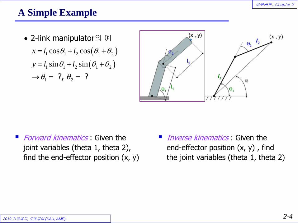
A Simple Example
▪ Inverse kinematics : Given the
end-effector position (x, y) , find
the joint variables (theta 1, theta 2)
( )
( )
1 1 2 1 2
1 1 2 1 2
1 2
cos cos
sin sin
x l l
y l l
•
= + +
= + +
→ = =
2-link manipulator
?, ?
의 예
▪ Forward kinematics : Given the
joint variables (theta 1, theta 2),
find the end-effector position (x, y)

2019 가을학기, 로봇공학 (KAU, AME)
로봇공학, Chapter 2
2-5
2.3 Robot Mechanism
▪ Manipulator-type robot의 특징
• 다물체(multi-body), 다자유도 시스템(multi-degrees of freedom system)
• 3차원 open-loop chain 메커니즘
➢ 각 joint 및 link에서의 error가 end-point 까지 누적: Fig. 2.2(b)
→ 내부센서(조인트 각 측정) 만으로는 실제 말단위치 측정 부정확
→ 극복방법: 로봇 말단 위치를 외부센서(Camera, laser sensor 등)로 측정
0x0y
0z
1x 1y
1z
2x 2y
2z
1 ( )nx n
( )ny o
( )nz a
23
n
0
nT

2019 가을학기, 로봇공학 (KAU, AME)
로봇공학, Chapter 2
2-6
Robot Mechanism
▪ Closed-loop mechanism VS. Open-loop mechanism
(a) Closed-loop mechanism (b) open-loop mechanism
One active joint
Three active joints→ 3DOF manipulator
Four-bar mechanism(1 DOF, closed-loop)
passive joints

2019 가을학기, 로봇공학 (KAU, AME)
로봇공학, Chapter 2
2-7
2.4 Matrix Representation (Position)
▪ 공간상의 점 위치 → 벡터로 표현
A point P in space :3 coordinates relative to
a reference frame
^^^
kcjbiaP zyx ++=
Fig. 2.4 Representation of a point in space Fig. 2.5 Representation of a vector in space
A vector P in space :3 coordinates of its tail and of its head
^^^__
kcjbiaP zyx ++=
=
w
z
y
x
P__
w: scaling factor

2019 가을학기, 로봇공학 (KAU, AME)
로봇공학, Chapter 2
2-8
Matrix Representation (Orientation)
▪ 기준좌표계에 대한 회전좌표계의 자세 표현 (Fig. 2.7)
( , , )
( , , )
x x x
y y y
z z z
n o a
x y z
n o a
F n o a
n o a
=
(direction cosines)
(Rotation matrix): 회전좌표계 각 축이
고정좌표계 각 축과 이루는
방향코사인으로 구성
unit vectors
Fig. 2.7 Representation of a frame at the origin of the reference frame
Each Unit Vector is mutually perpendicular: normal, orientation, approach vector

2019 가을학기, 로봇공학 (KAU, AME)
로봇공학, Chapter 2
2-9
Matrix Representation (Position & Orientation)
▪ 기준좌표계(고정)에 대한 이동좌표계(회전+위치이동)의 표현 (Fig. 2.8)
0 0 0 1
x x x x
y y y y
z z z z
n o a p
n o a pF
n o a p
= →
Rotation matrix + translation vector
Robot hand (Gripper)=end-effector
( )nn x
( )no y
( )na z
Fig. 2.8 Representation of a frame in a frame
• Example:

2019 가을학기, 로봇공학 (KAU, AME)
로봇공학, Chapter 2
2-10
강체(Rigid Body)의 표현 (자세 및 위치)
▪ 3차원 공간 상의 강체 (로봇의 각 link) (Fig. 2.10)
Fig. 2.10 Representation of an object in space
An object can be represented in space by attaching a frameto it and representing the frame in space.
=
1000
zzzz
yyyy
xxxx
object
Paon
Paon
Paon
F
• 강체에 이동좌표계(moving frame) (n,o,a) 부착
기준좌표계에 대한 이동좌표계(강체)의
위치(position) 및 자세(orientation)의 변화
→ 4 x 4 transformation matrix로 표현

2019 가을학기, 로봇공학 (KAU, AME)
로봇공학, Chapter 2
2-11
강체(Rigid Body)의 표현
▪ 3차원 공간상의 강체 (로봇의 각 link)
→ 기준좌표계(Reference frame)에 대하여 6자유도 운동
➢ (x,y,z) 각 축 방향의 translation (3DOF)
➢ (x,y,z) 각 축에 대한 Rotation (3 DOF)
( , , )
0 0 0 1
x x x x
y y y y
object x y z
z z z z
n o a p
n o a pF p p p
n o a p
= →
Rotation + translation
강체의 Rotation(3 DOF 운동)에대한 9개의 정보→ 6개의 constraints(구속조건)
포함 (2.10)식
강체의 translation(3 DOF 운동)에대한 3개의 정보

2019 가을학기, 로봇공학 (KAU, AME)
로봇공학, Chapter 2
2-12
Rotation Matrix의 성질
0 0 0 1
x x x x
y y y y
object
z z z z
n o a p
n o a pF
n o a p
=
0n o o a a n
•
→ = = =
•
Rotation matrix : (2.10), (2.11)
Three unit vectors are mutually orthogonal
dot product = 0 :
The length of each unit vector = 1
특성
1n o a→ = = =

2019 가을학기, 로봇공학 (KAU, AME)
로봇공학, Chapter 2
2-13
2.5 Homogeneous Transformation Matrix
▪ 기준좌표계에 대한 강체의 위치(position) 및 자세(orientation)의 변화
→ 4 x 4 homogeneous transformation matrix로 표현
▪ Transformation matrices must be in square form.
• It is much easier to calculate the inverse of square matrices.
• To multiply two matrices, their dimensions must match.
3 3 3 1
1 3
0 0
1
0 1
0
x x x x
y y y y
z z z z
n o a p
n o a pF
n o a p
R p
•
=
Homogeneous transformation matrix
1 1 2 2 1 11 2 2 2 1
1 2 1 2
1 2,
0 1 0 1 0 1 1 0 10
R p R p R p R pF F F F
R R p R p
•
= = → = =
+
Homogeneous transformation matrix
(Ex.)
의 연산

2019 가을학기, 로봇공학 (KAU, AME)
로봇공학, Chapter 2
2-14
2.6 Transformations (강체의 이동 및 회전)
( , , )
0 0
0 0(
1
1
1
1
, , )0 0
0 0 0 1
0 0
0 0
0 0
0 0 0 1
1
1
x y z
x
y
x y z
z
x x x x x
y y y y
new
Trans d
z
d d
d
dT Trans d d d
d
d n o a p
d n o a pF
d
=
=
•
(Fig. 2.11)
Pure translation location
에 의한 의 변화
Pure translation1)
0 0 0 1 0 0 0 1
( , , )
old
x x x x x
y y y y y y
z z z z z z z z z
new x y z old
F
n o a p d
n o a p d
n o a p n o a p d
F Trans d d d F
+
+ = +
=
Pure translation Pure rotation about an axis Combination of translations or rotations.
(강체의 이동에 의한 위치 변화)

2019 가을학기, 로봇공학 (KAU, AME)
로봇공학, Chapter 2
2-15
Transformations: Pure rotation about an axis
1 0 0 0
0 c 0
0 c 0
0 0 0 1
1 0 0
( , ) 0 c
0 c
c 0
( , ) 0 1 0
0 c
s
sRot x s
s
s
Rot y
s
−
•
= − =
= −
:
(Fig. 2.12, 2.13)
Rotation matrices
x-axis
: y-axis
기준좌표계 에 대하여 만큼 회전
기준좌표계 에 대하여
Pure Rotatio2) n
c 0
( , ) c 0
0 0 1
s
Rot z s
−
=
: z-axis
만큼 회전
기준좌표계 에 대하여 만큼 회전

2019 가을학기, 로봇공학 (KAU, AME)
로봇공학, Chapter 2
2-16
1 0 0
( , ) 0 c
0 c
x n
xyz noa y o
z a
U U R
R
P P
P Rot x P P s P
P s P
P T P
= = −
→ = simply
R
noaP P=
Rotation about the x-axis.
U
xyzP P=
Fig. 2.13 → (2.17) → (2.18)
x x x
y y y
z z z
n o a
F n o a
n o a
=
* Direction cosine matrix= Rotational matrix
(강체의 회전에 의한 위치 변화)

2019 가을학기, 로봇공학 (KAU, AME)
로봇공학, Chapter 2
2-17
Transformations: Combined transformations
( , ) ( , ) ( , ) ( , )Rot x Rot y Rot y Rot x
•
(Translation + Rotation)
Successive transformation
- Rotation
- Translation (Pure translation ):
의 경우 순서가
의 경
중요:
은 순서에 무 우
관
Combined Transformation 3)
( , , ) ( , , ) ( , , ) ( , , )
( , ) ( , , ) ( , ) ( , , )
x y z x y z x y z x y z
x y z x y z
Trans p p p Trans d d d Trans d d d Trans p p p
Rot x Trans p p p Rot y Trans d d d
Tran
→
•
=
→ →
(Reference frame) successive transformation:
=
기준좌
표
계 에 대한
( , , ) ( , ) ( , , ) ( , )x y z x y zs d d d Rot y Trans p p p Rot x
Premulti pl g! yin →

2019 가을학기, 로봇공학 (KAU, AME)
로봇공학, Chapter 2
2-18
(Ex.) Transformation Matrix의 계산
0 0 0
0 0 0
0 0 0
1
( , ) ( , , ) (
( , , )
( , , ) ( , , )
( ,
, ) ( , , )
( , , ) ( , ) ( , ,, ) ( , , )) ( , )
x y z x y z
x y z x y z
R x Tr b b b R y Tr d d d
Tr d d d R y Tr b b
p x y z
p x y z x y z
p x y z b R x y zx
• → →→ →
→
=
→
(reference frame) transformation:
=
임의점 의 기준좌표계 에 대한
초기위치 최종위치
최종위치 초기위치
0
0
0
0 0 0
0 0 0
0 0 0
0 0 c 0 0 1 0 0 1 0 0 0
0 1 0 0 1 0 0 0 1 0 0 c 0
0 0 1 0 c 0 0 0 1 0 c 0
0 0 0 1 0 0 0 1 0 0 0 1 0 0 0 1 0 0 0 1
c 0
0 1 0
0 c
0 0 0
x x
y y
z z
x
y
z
x x x
y y y
z z z
d s b n o a x
d b s n o a y
d s b s n o a z
s d
d
s d
−
−
−
=
0
0
0
0 0 0
0 0 0
0 0 0
1 0 0
0 c
0 c
1 0 0 0 1 0 0 0 1
0 0 0 1
, ,
x
y
z
x x x
y y y
z z z
x x x x
y y y y
x y z
z z z z
b n o a x
s b n o a y
s b n o a z
n o a p
n o a p
n o a px p y p z p
−
= = = =
. Then, we have
강체(Point p)에 부착된 회전좌표계의reference frame에 대한 초기자세
강체(Point p)에 부착된 회전좌표계의reference frame에 대한 최종자세
강체(Point p)의초기위치
강체(Point p)의 최종위치

2019 가을학기, 로봇공학 (KAU, AME)
로봇공학, Chapter 2
2-19
2.6.4 회전좌표계에 대한 상대 변환 (Relative Transformation)
( , ) ( , , ) ( , ) ( , , )x y z x y zRot x Trans p p p Rot y Trans d d d
R
→ → →
•
→
•
Robot link
link
successive transformation :
Current frame = (
( )
=
Rotating frame
)회전
의 운동
각 에 부착된 회전좌표계에 대한
좌표계
상대운동으로 기술
에 대한
예
0 1 21 2
( , ) ( , , ) ( , ) ( , , )x y z x y z
ET T T
ot x Trans p p p Rot y Trans d d d
• ⎯⎯→ ⎯⎯→ ⎯⎯⎯→
reference rotating rotating end-effector
frame 0 frame 1 frame 2 frame E
Postmultiply
Referen
ing!
ce f
→
0 0 1 2
1 2
0 0 0 1
x x x x
y y y y
E
z z z
E
z
n o a p
n o a p
n o a pT T T T
=
=
rame{0} end-effector{E} 에 대한 의 위치 및 자세
자세(orientation)
위치(position)

2019 가을학기, 로봇공학 (KAU, AME)
로봇공학, Chapter 2
2-20
Fig. 2.17 Transformations relative to the current(=rotating) frames.
Example 2.100 0( ,90 ) (4, 3,7) ( ,90 )xyz noaP Rot a Trans Rot o P= −
0( ,90 )Rot a
(4, 3,7)Trans −
0( ,90 )Rot o
7
3
2
noaP
=
0
6
0
xyzP
=

2019 가을학기, 로봇공학 (KAU, AME)
로봇공학, Chapter 2
2-21
로봇 핸드의 위치 및 자세
0 0 1 2 1
1 1 2 2 3 3( ) ( ) ( ) ( )n
n n nT T T T T −
•
→ =
Robot hand(end-effector)
reference frame (position/orientation)
의
에 대한 좌표
0
0 0 0 1
x x x x
y y y y
n
z z z z
n o a p
n o a pT
n o a p
=
1 0 0 0
1
~ ( , , )
( , , ) , , )
( , , ) , , )
~
reference frame hand
position: orient forward kation: (
hand : (
joint ang
inematics.
le( )
n
x y z
x y z
n
x y z
p p p p n o a
p p p p n o a
→
•
=
• =
주어진 에 대하여 에 대한 의
과 을 구하려면
원하는 위치 와 자세 에 대하여
을 구하려면 Inverse kinema tics.→
0x0y
0z
1x1y
1z
2x 2y
2z
1 ( )nx n
( )ny o
( )nz a
23
n
0
nT
3x 3y
3z

2019 가을학기, 로봇공학 (KAU, AME)
로봇공학, Chapter 2
2-22
2.7 Inverse of Transformation Matrices
Fig. 2.16>
: Reference frame, : Robot Base frame,
: Hand frame, : end-effector frame,
: Part fra
Unknown : Robot base(R) h (
m
an
e
d H
R
H
R
U U H U P
E R E P E
U R
H E
H
P
T T T T TT
T
= =
• 에 대한 ) transformation
Forward kinematics →
의
로 결정됨
Fig. 2.16 The Universe, robot, hand, part, and end effecter frames.
( ) ( )( )
( ) ( )( )
( ) ( )( )
( )
( ) ( )
1 1
1 1
1 1
1 1
,
U U H H
R R E E
U U P H
R P E E
U U P H
R P E E
R U P E R
U P E H H
U
R
H
R H E
R U E
R
H
H
T T T T
T T T T
T T T T
T
T
T
T T T T
T T T T
− −
− −
− −
− −
=
→ =
=
= =
=

2019 가을학기, 로봇공학 (KAU, AME)
로봇공학, Chapter 2
2-23
1
1
0 0 0 1
0
( , ) ( , )
1
x x x x
y y y y
z z z z
T
T
n o a p
n o a p
n o a p
p
R R
RT
RT
x x −
−
• →
→ =
=
= =
Rotation matrix Inverse
Rotation matrix orthogonal matrix!
: unitary matrix
Transformation matrix Inverse
의
의
0 0 0 1
0 1
,
x y z
x y z
x y z
T
x x x x
y y y y
z z z z
n n n p n
o o o p o
a a a p a
p
p n o a
R
p n o a
p n o a
p n o a
−
−
−
−
= = = =
=
, where ,

2019 가을학기, 로봇공학 (KAU, AME)
로봇공학, Chapter 2
2-24
2.8 Forward & Inverse Kinematics of Robots
▪ 공간상에서 기준좌표계(reference frame)에 대한 강체(rigid body)의 위치
(position)와 자세(orientation)을 구하기 위해서는
• 강체에 강체와 함께 움직이는 이동좌표계를 부착하고
• 이동좌표계 원점의 위치[(x,y,z):3 DOF]와
• 이동좌표계 각 축의 기준좌표계에 대한 자세[방향코사인 또는 Euler angle: 3
DOF]를 구함.
▪ Robot의 경우 (Fig. 2.17)
• Robot hand(= 강체)에 이동좌표계 (n,o,a)를 부착
• 로봇 각 링크의 parameter 값들과 주어진 joint angle에 의해 기준좌표계에 대한
이동좌표계(n,o,a) 원점의 위치와 자세를 결정.
Robot hand(Gripper)=end-effector
( )nn x
( )no y
( )na z

2019 가을학기, 로봇공학 (KAU, AME)
로봇공학, Chapter 2
2-25
2.9 Kinematic Equations for Position
( , , )
1 0 0
0 1 0
0 0 1
0 0 0 1
x
yR
P
z
x y z
p
pT
p
•
=
Cartesian coordinates (Fig. 2.18):
( , , )
( , , ) (0,0, ) ( , ) ( ,0,0)
1 0 0 0 0 0 1 0 0
0 1 0 0 0 0 0 1 0 0
0 0 1 0 0 1 0 0 0 1 0
0 0 0 1 0 0 0 1 0 0 0 1
R
P cyl
r l
T T r l Trans l Rot z Trans r
c s r
s c
l
•
= =
−
Cylindrical coordinates (Fig. 2.19):
=
0
0
0 0 1
0 0 0 1
c s rc
s c rs
l
−
=
A gantry robot is a Cartesian robot.
2 Linear translations and 1 rotation

2019 가을학기, 로봇공학 (KAU, AME)
로봇공학, Chapter 2
2-26
( , , )
( , , ) ( , ) ( , ) (0,0, )
0 0 0 0 1 0 0 0
0 0 0 1 0 0 0 1 0 0
0 0 1 0 0 0 0 0 1
0 0 0 1 0 0 0 1 0 0 0 1
R
P sph
r
T T r Rot z Rot y Trans r
c s c s
s c
s c r
•
= =
− −
Spherical coordinates (Fig. 2.20):
=
0
0 0 0 1
C C S S C rS C
C S C S S rS S
S C rC
−
−
=
1 2( , , , )n
•
→
Articulated coordinates (Fig. 2.21):
Robot
D-H transformation
관절형 의 경우:
방법에 따른
1 Linear translation and 2 rotations

2019 가을학기, 로봇공학 (KAU, AME)
로봇공학, Chapter 2
2-27
2.10 Kinematic Equations for Orientation
2.10.1(a) Roll-Pitch-Yaw (RPY) angles
( ,
( , , )
( , ) ( , ) ( ,
, )
)
a o n
a o nRot a Rot o Rot
a o n
n
• = = =
→ → → →
about curren
Roll-Pitch-Yaw (RPY) angles (Fig. 2.22):
* RPY sequence of rotation
: (z y x )
:Current frame
t axes:
(회전좌표계의 현재 자세)에 대한 상대회전
Yaw: Rotation of about -axis (x-axis of the moving frame)n n
Roll: Rotation of about -axis (z-axis of the moving frame)aa
Pitch: Rotation of about -axis (y-axis of the moving frame)o o
( , , ) ( , , ) ( , ) ( , ) ( , )
0 0 0 0 1 0 0 0
0 0 0 1 0 0 0 0
0 0 1 0 0 0 0 0
0 0 0 1 0 0 0 1 0 0 0 1
a o nRPY RPY Rot a Rot o Rot n
c s c s
s c c s
s c s c
= =
−
− −
=

2019 가을학기, 로봇공학 (KAU, AME)
로봇공학, Chapter 2
2-28
( , , )
( , , )
( , ) ( , ) ( , )
0
0
0
0 0 0 1
a o nRPY
RPY
Rot a Rot o Rot n
c c c s s s c c s c s c
s c s s s c c s s c c c
s c s c c
=
=
− +
+ − −
=
(2-36)식 ( , )nRot n
( , )aRot a ( , )oRot o
Roll-Pitch-Yaw (RPY) angles

2019 가을학기, 로봇공학 (KAU, AME)
로봇공학, Chapter 2
2-29
( , , ) ( , ) ( , ) ( , )
0
0
0
0
0
0
0
0 0 10 1 0 0
x x x
y y y
z z z
RPY Rot a Rot o Rot n
c c c s s s c c s c s c
s c s s s c c s s c
n o a
n o a
n
c c
s oc c as c
=
− +
+ − −
= =
( )nn x
( )no y
( )na z
Roll-Pitch-Yaw (RPY) angles
•
→
End-effector orientation)
(robot base) end-effector RPY angle
의 자세(
기준좌표계 에 대한 좌표계의
2 2
2 2
tan tan tan
atan2( , )
atan2( , )
atan2( , )
y z z
x zz z
y x
z z z
z z
n n o
n ao a
n n
n o a
o a
−= = =
+→
=
= − +
=
, ,
Roll:
Pitch:
Ya :
w
RPY angles Direction cosines

2019 가을학기, 로봇공학 (KAU, AME)
로봇공학, Chapter 2
2-30
2.10.2(b) Euler Angles
( , ) ( , ) (
( )
, )
, ,
Rot a Rot o Rot a
a o
z
a
•
→
→ → → →
about cu
Euler angle (Fig. 2.24):
RPY angle Euler angle
* Euler angle
: (z y )
:Current fr
rrent ax
ame(
es:
책마다 정의가 약간씩 다름.
도 의 한 종류.
회전순서
현
( , , ) ( , ) ( , ) ( , )
0 0 0 0 0 0
0 0 0 1 0 0 0 0
0 0 1 0 0 0 0 0 1 0
0 0 0 1 0 0 0 1 0 0 0 1
Euler Rot a Rot o Rot a
c s c s c s
s c s c
s c
=
− − −
=
= (2-43)
( ) RPY angle
재의 회전좌표계)에 대한 상대회전
식
주 의 .정의만 잘 익힐 것

2019 가을학기, 로봇공학 (KAU, AME)
로봇공학, Chapter 2
2-31
, ,( ) ( , , )
1 0 0 0
0 1 0 0
0 0 1 0
0 0 0 1 0 0 0 1
x y z
x
y
R
H car
z
t
x
T T RPY
c c c s s s c c s c s c
s c s s s c c s s c c c
s c s c c
c c c s s s c c s
p p p
p
p
p
pc s c
s s s s s c c
=
− +
+ − −
− +
+
=
=
1 1 2 2 1 2 1 1 2
3 3 3 1 21 3 3 3 1 ( , 0
0 0 0 1 0 0 0 1
0 1 1 0 1)
0
x x x x
y y y y
z z
y
z z z
n o a p
s s c c c n o a p
s c s c c n o a p
R P R P R R P R P
p
p
R I P
− = −
+=
= =
( ) 주
Forward Kinematic Equations
▪ Reference frame(기준좌표계 R) = Cartesian frame(직교좌표계)
▪ Robot hand의 자세를 기준좌표계에 대한 RPY angle로 표현한다면,
Robot hand 즉, 이동좌표계 (n, o, a)의 위치(location) 및 자세(Orientation)는?
2019 가을학기, 로봇공학 (KAU, AME)
로봇공학, Chapter 2
2-32
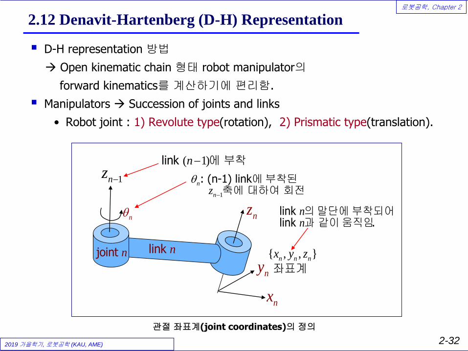
2.12 Denavit-Hartenberg (D-H) Representation
▪ D-H representation 방법
→ Open kinematic chain 형태 robot manipulator의
forward kinematics를 계산하기에 편리함.
▪ Manipulators → Succession of joints and links
• Robot joint : 1) Revolute type(rotation), 2) Prismatic type(translation).
nz
joint n link n
nn
link link .
의 말단에 부착되어과 같이 움직임
n
1
n
nz
−
: (n-1) link
에 부착된 축에 대하여 회전
{ , , }
n n nx y z
좌표계
1 nz −
( 1)link n− 에 부착
nx
ny
관절 좌표계(joint coordinates)의 정의

2019 가을학기, 로봇공학 (KAU, AME)
로봇공학, Chapter 2
2-33
D-H Parameters
1nz −
nz2nz − n
1n +
1n −
joint n1joint n−
1link n−
link n
( )1attached to link n−
( )attached to link n
( )2attached to link n−
1nx −
nxna
nd
n
n
o
o
▪ Transformation between two successive frames
21 1
1
1
1
n
n n n
n
n
n
n
d
a
− −−
−
−
−
•
•
•
→
→
z
x common normal between z z
y
-axis: n-th joint (revolute joint )
or (prismatic joint
variable
)
-axis: along the -axis
variab
& -axis
-axi
le
s: f
이
이
의 회전방향
직선운동 방향
ollows right-hand rule
1na
−

2019 가을학기, 로봇공학 (KAU, AME)
로봇공학, Chapter 2
2-34
두 관절 좌표계 사이의 변환(Transformation)
1 1 1
1
1( (0,0,
{ , , } { , , }
, ) ) ( ,0,0) ( , )n
n
n
n
n n n n n n
n
n n n n n
n n n nd a
Rot z Trans d
x y z x y z
T Trans a Rot x
− − −
−
−
→ → →
•
⎯⎯⎯⎯⎯⎯⎯→
=
: x
transformation:
(n-1) link n-link
두 좌표계 사이의
좌표계 좌표계
1 1
1 1
n
n nn
n n n
n n n
d
a
− −
− −
x : z z
: x x z : z
축과 축 사이 각도 축과 축 원점 사이의 거리
축과 축 사이의 거리 축과 축 사이 각도
1
1
1
1
1(
(0,0,
(
( ,
, )
)
,0,0)
)
n n n
n n n
n n n
n n n n
nRot z
Trans d
Trans a
Rot x
−
−
−
−
−•
•
•
•
→
→
→
→
x x
x x colinear
x x .
z z
축이 축과 평행하게 됨.
축과 축이 하게 됨.
축의 원점이 축의 원점과 일치하게 됨
축이 축과 일치하게 됨.

2019 가을학기, 로봇공학 (KAU, AME)
로봇공학, Chapter 2
2-35
두 이동좌표계 사이의 Transformation
1
1( (0,0,, ) ) ( ,0,0) ( , )
0 0 1 0 0 0 1 0 0 1 0 0 0
0 0 0 1 0 0 0 1 0 0 0 0
0 0 1 0 0 0 1 0 0 1 0 0 0
0 0 0 1 0 0 0 1 0 0 0 1 0 0 0 1
n n
n
n
n
n n n n n n
n n
n n n n
n n
Rot z Trans d
a
d
T A Trans a Rot x
c s
s c c s
s c
−
−= =
−
− =
0 0 1 0 0
0 0 0 0
0 0 1 0 0
0 0 0 1 0 0 0 1
0
0 0 0 1
n
n
n
n
n
n n
n n n n
n n
n n n n n n
n n n n n n
n n
a
d
a
a
d
c s
s c c s
s c
c s c s s c
s c c c s s
s c
−
− =
−
− =
{n-1}좌표계에 대한 {n}좌표계의 자세
{n-1}좌표계 원점에 대한{n}좌표계 원점의 거리

2019 가을학기, 로봇공학 (KAU, AME)
로봇공학, Chapter 2
2-36
(Robot Base → Hand)의 Transformation
▪ Robot base(Reference frame)에 대한 Robot hand의 위치 및 자세
1 2 1
1 1 2 2 3 3 1 2 3( ) ( ) ( ) ( )
: revolute joint variable
: prismatic joint
i i
i i
R R n
H n n n
q
q d
T T q T q T q T q A A A A
−
=•
=
= =
0x0y
0z
1x1y
1z
2x 2y
2z
1 ( )nx n
( )ny o
( )nz a
23
n
0
nT
3x 3y
3z
x y
z

2019 가을학기, 로봇공학 (KAU, AME)
로봇공학, Chapter 2
2-37
Example 2.25 (PUMA type)
▪ D-H parameters
Joint # theta[i] d[i] a[i] alpha[i]
1
2
3
4
5
6
0x 0y
0z
6x6y
6z

2019 가을학기, 로봇공학 (KAU, AME)
로봇공학, Chapter 2
2-38
Example 2.26 (Stanford Arm)
▪ D-H parameters (Table 2.6)
Joint # theta[i] d[i] a[i] alpha[i]
1
2
3
4
5
6
0x 0y
0z
6x
6y6z

2019 가을학기, 로봇공학 (KAU, AME)
로봇공학, Chapter 2
2-39
2.13 Inverse Kinematic Solutions
▪ Position level (chap. 2)에서의 Inverse kinematics
• 특별한 규칙이 있는 것은 아니고 주로 기하적 방법(geometric
method)이나 transformation matrix의 element를 비교해서
solution을 찾음.
• 6DOF robot의 역기구학 해가 존재하기 위한 충분조건:
→ The last three revolute joint axes (wrist) intersects at a common
point.
0 0 0 1
x x x x
y y y y
z z z z
i
i
n o a p
n o a p
n o a p
d
•
Given the desired location:
& orientation of the robot
(revolute joint) or
Inv
Solve f
erse kinem
or the joint variables: (prismatic joi
atic
nt)
s

2019 가을학기, 로봇공학 (KAU, AME)
로봇공학, Chapter 2
2-40
Ex. 2.25의 역기구학 해
1 1 2 2 3 3 4 4 5 5 6 6
1
6 6 6
1
0 0 0 1
( ) ( ) ( ) ( )
, , }
, , }
( ) ( ) [ ]
(1)
Desired orientation/location
: {
{ frame
of the hand
x x x x
y y y y
z z z z
x x x x
y y
R
H
n o a p
n o a p
n o a p
n o a p
n o
x y
T A A A A A A RH
z
n a
S
A
o
−
• =
=
=
1
1 2 2 3 3 4 4 1 3
5 2
5 5 6 6
1 1 1 1 1 1 1 1
4 3 2 1 4 3 2 1 5 5 6 6
1
34 2
5
4
0 0 0 1
0 0 0 1
[ ] ( ) ( ) ( ) ( ,
,
) ( )
(2) [ ] ( ) ( )[ ]
(3)
, ,
y y
z z z z
x x x x
y y y y
z z z z
a p
n o a p
n o a p
n o a p
n o a p
A RHS A A A A A
A A A A A A A A RHS A A RHS
A A
−
− − − − − − − −
−
= =
= =
→
→
1 1 1 1 1 1 1 1 1
4 3 2 1 4 3 1 65 2 6 6
0 0 0 1
[ ] ( )
x x x x
y y y y
z z z z
n o a p
n o a p
n o a pA A A A A A A A RHS A − − − − − − − − −
= =
→

2019 가을학기, 로봇공학 (KAU, AME)
로봇공학, Chapter 2
2-41
Ex. 2.26 (Stanford Arm)의 역기구학 해
▪ 5R-1P manipulator
1 1 2 2 3 3 4 4 5 5
6 6
6 6
6
0 0 0 1
( ) ( ) ( ) ( ) ( ) ( ) [ ]
(1
, , }
, , }
)
1st three joints
Desired orientation/location
: of the {
{
ha
frame
nd
x x x x
y y y y
z z z z
R
H
n o a p
n o a p
n o a px y
T A A A
z
A A A RHS
n o a
•
=
=
=
3
3
2
21 1
1 6 2 2 3 3 4 4 5 5
2
1 1 1
3
2 3
1
1
2
0 0 0 1 0 0 0 1
0 0 0 1
( ) ( ) ( ) , ,( )
(2)
[
last three joints
known matr
x x x x
y y y y
z z z z
x x x x
y y y y
z z z z
n o a p d
n o a p d
n o a p d
n o a p
n o a p
n o a p
s
cA A A A A A
A A A
− −
− − −
−
= =
=
→
4 4 5 5 6 6
1
4 5 5 6 6 4 5 6
( ) ( ) ( )
[ ( ) ( , ,)
ix]
known matrix]
A A A
A A A
− →
=
=

2019 가을학기, 로봇공학 (KAU, AME)
로봇공학, Chapter 2
2-42
2.15 Degeneracy and Dexterity
▪ Degeneracy
• Robot이 운동 중에 singular configuration에 들어가
degree of freedom 을 잃는 경우가 발생
1) Robot의 각 joint가 물리적 한계에 도달하는 경우 (즉, robot의
운동 영역인 workspace의 경계에 있는 경우)
2) 두개 joint의 z-axis가 colinear한 경우: 어느 축을 움직여야 하
는가 결정할 수 없음.
▪ Dexterity
• Robot hand를 workspace내의 임의 point에 원하는
orientation으로 위치시킬 수 있을 때 robot이
dexterous하다라고 말함.
• Robot workspace의 경계(boundary) 부분에는 hand를
원하는 자세로 보낼 수 없음. (dexterity를 잃는 경우)

2019 가을학기, 로봇공학 (KAU, AME)
로봇공학, Chapter 2
2-43
2.16 Fundamental Problem with D-H Representation
▪ Defect of D-H presentation :
• D-H cannot represent any motion about the y-axis, because all motions
are about the x- and z-axis (Standard D-H 방법의 경우)

2019 가을학기, 로봇공학 (KAU, AME)
로봇공학, Chapter 2
2-44
㈜ D-H 변환에서 Y축으로의 이동이 필요한 경우 (PUMA560)
1nz −
nz2nz − n
1n +
1n −
joint n1joint n−
1link n−
link n
( )1attached to link n−
( )attached to link n
( )2attached to link n−
1nx −
nxna
nd
n
n
o
onb
1
1
1
1
1(
(0,0,
(
,
(
(
, )
)
,0,0
0
)
,0)
)
,
n n n
n n n
n n n
n n
n
n
n
nRot z
Trans d
Trans a
Rot
Tran b
x
s
−
−
−
−
−•
•
•
•
•
→
→
→
→
→
x x
x x parallel
x x colinear )
x x
z
축이 축과 평행하게 됨.
축과 축이 하게 됨.
축과 축이 하게 됨 (동일직선상 .
축의 원점이 축의 원점과 일치하게 됨
1n n− z 축이 축과 일치하게 됨.

2019 가을학기, 로봇공학 (KAU, AME)
로봇공학, Chapter 2
2-45
1
1( (0,0,, ) ) ( ,0,0) ( , )
0 0 1 0 0 0 1 0 0
0 0 0 1 0 0 0 1 0 0
0 0 1 0 0 0 1 0 0 1 0
0 0 0 1 0
(0, ,0)
1 0 0 0
0 1 0
0 0 1 0
00 0 01 0 00 0 1 1
n n
n
n
n
n
n n n n n n
n n
n n
nRot z Trans d
d
b
a
T A Trans a Rot x
c s
Tra
s c
ns b
−
−= =
− =
1 0 0 0
0 0
0 0
0 0 0 1
0
0 0 0 1
n n
n
nn
n
n n
n n
n n n n n n
n n n n n
n
nn
n
a
a
d
c s
s c
c s c s s c
s c c
b s
bc
s
cs s
c
−
−
− =
−
+
㈜ D-H 변환에서 Y축으로의 변환이 필요한 경우 (PUMA560)
1 1 1
1
1( (0,0,
{ , , } { , , }
, ) ) ( ,0,0) (0, ,0) ( ,n n
n n n n n n
n
n n n nn
n n n nnd ba
Rot z Trans d
x y z x y z
T Trans a Trans R tb o x
− − −
−
−
→→ → →
•
⎯⎯⎯⎯⎯⎯⎯⎯⎯→
=
transformation:
(n-1) link n-link
두 좌표계 사이의
좌표계 좌표계
1 1
111
)
n n
n
n n n n
n n nn nnn n
n
b
d
a
− −
− −−
: x x : z z
: x x : z : y y z
축과 축 사이 각도, 축과 축 사이의 거리,
축과 축 사이의 거리, 축과축과 축 사이의 축 사거리, 이 각도

2019 가을학기, 로봇공학 (KAU, AME)
로봇공학, Chapter 2
2-46
PUMA560
Joint # theta[i] d[i] a[i] b[i] alpha[i]
1
2
3
4
5
6
2019 가을학기, 로봇공학 (KAU, AME)
로봇공학, Chapter 2
2-47
▪ Methods for representation of points, vectors, frames, and 4 by 4
homogeneous transformations by matrices.
▪ Forward and inverse kinematics of robots
▪ RPY angles and Euler angles
▪ Denavit-Hartenberg method to derive the forward and inverse
kinematic equations
Summary of Chapter 2

2019 가을학기, 로봇공학 (KAU, AME)
로봇공학, Chapter 2
2-48
[Homework #1] (220점)
▪ 예제 Example 2.9 ~ 2.28 (20 x 5점 = 100점)
(번역서: Example 2.1~2.20)
▪ Solve the following problems in chapter 2: (10점 x 7=70점)
• 2.6, 2.11, 2.14, 2.19, 2.30, 2.31, 2.32
(번역서: 2.3, 2.7, 2.9, 2.12, 2.20, 2.21, 2.22)
▪ Solve the forward/inverse kinematics of the stanford arm. (50점)
• Derive the Eq. (2.60): forward kinematics :번역서 (2.58)
• Derive the Eq. (2.80)~(2.85): inverse kinematics :번역서 (2.78)~(2.83)
(Ref.) Asada and Slotine “Robot analysis and control”

2019 가을학기, 로봇공학 (KAU, AME)
로봇공학, Chapter 2
2-49
H.W#1 2.32 문제 (번역서 2.22)
1) Ref. frame을 1번 joint에 둘 경우
Joint # theta d a alpha
1 theta1 0 0 90
2 0 l2 0 -90
3 theta3 0 0 90
H 0 l3 0 0
2) Ref. frame을 Text와 같이 둘에 둘 경우
Joint # theta d a alpha
U 0 0 l1
1 theta1 0 0 90
2 0 l2 0 -90
3 theta3 0 0 90
H 0 l3 0 0
0 0 1 2 3
1 2 3H HT A A A A=
0 0 1 2
0 0 1 2 3
U U U
H HT A T A A A A= =