chapter 7 viewing and transformations © 2008 cengage learning emea
TRANSCRIPT

CHAPTER 7CHAPTER 7
Viewing and TransformationsViewing and Transformations
© 2008 Cengage Learning EMEA

LEARNING OBJECTIVESLEARNING OBJECTIVES In this chapter you will learn about:
– 3D Cartesian coordinate systems– The synthetic-camera model– The viewing system– The view volume– Culling– Clipping– Changing coordinate systems– Viewing transformations– The modeling/world transformation– The projection transformation– The viewport transformation
LEARNING OBJECTIVESLEARNING OBJECTIVES In this chapter you will learn about:
– Spatial transformations– Translation– Rotation– Scaling– Drawing a triangle without any
transformations– Drawing a triangle translated– Drawing a triangle rotated– Drawing a triangle scaled
3D CARTESIAN COORDINATE 3D CARTESIAN COORDINATE SYSTEMSSYSTEMS
The field of computer graphics relies heavily on vector calculations and matrix transformations.
These calculations, along with the Cartesian coordinate system, are based on numbers indicating distances.
The Cartesian coordinate system is consequently the most fundamental system for the unique identification of arbitrary points in space.
3D CARTESIAN COORDINATE 3D CARTESIAN COORDINATE SYSTEMSSYSTEMS
Two kinds of Cartesian coordinate systems:– two-dimensional– three-dimensional

3D CARTESIAN COORDINATE 3D CARTESIAN COORDINATE SYSTEMSSYSTEMS
A two-dimensional Cartesian coordinate system consists of an origin intersected by two axes perpendicular to each other. – The vertical axis is
known as the y-axis and the horizontal axis, the x-axis.
3D CARTESIAN COORDINATE 3D CARTESIAN COORDINATE SYSTEMSSYSTEMS
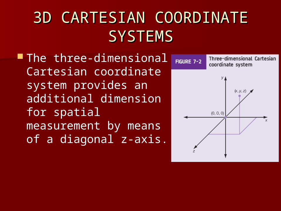
The three-dimensional Cartesian coordinate system provides an additional dimension for spatial measurement by means of a diagonal z-axis.
3D CARTESIAN COORDINATE 3D CARTESIAN COORDINATE SYSTEMSSYSTEMS
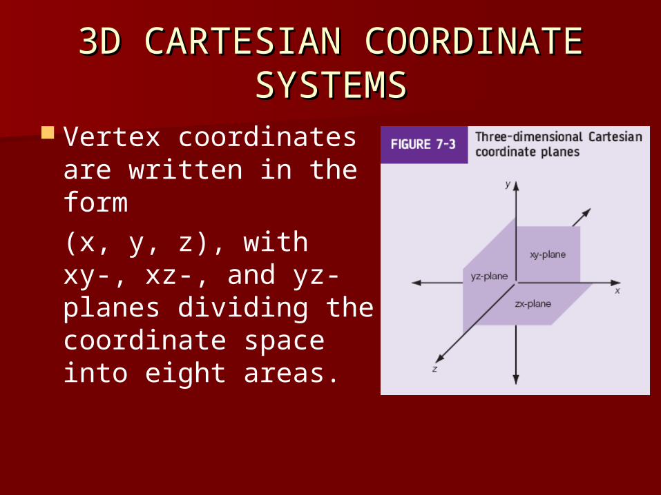
Vertex coordinates are written in the form (x, y, z), with xy-, xz-, and yz-planes dividing the coordinate space into eight areas.
3D CARTESIAN COORDINATE 3D CARTESIAN COORDINATE SYSTEMSSYSTEMS
Device independent coordinate systems function on the principle of translating between world and device or screen coordinates (the coordinate system used by the graphics display).
Graphics systems are primarily based on either the left-handed or right-handed Cartesian coordinate system.

3D CARTESIAN COORDINATE 3D CARTESIAN COORDINATE SYSTEMSSYSTEMS
THE SYNTHETIC-CAMERA THE SYNTHETIC-CAMERA MODELMODEL
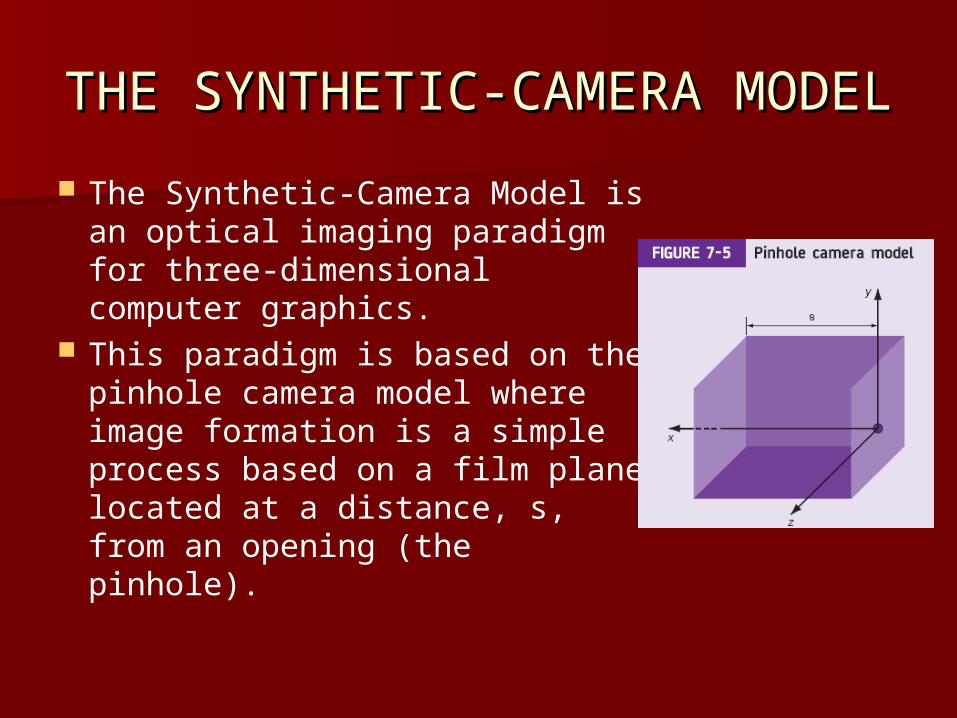
The Synthetic-Camera Model is an optical imaging paradigm for three-dimensional computer graphics.
This paradigm is based on the pinhole camera model where image formation is a simple process based on a film plane located at a distance, s, from an opening (the pinhole).
THE SYNTHETIC-CAMERA THE SYNTHETIC-CAMERA MODELMODEL
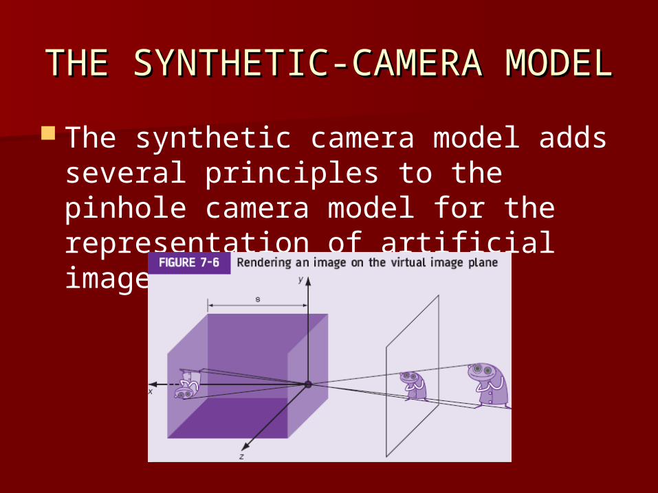
The synthetic camera model adds several principles to the pinhole camera model for the representation of artificial images.

THE SYNTHETIC-CAMERA THE SYNTHETIC-CAMERA MODELMODEL
The virtual image plane is also responsible for controlling the clipping of observed objects.
THE VIEWING SYSTEMTHE VIEWING SYSTEM
The viewing system is a unified model for image visualization and consists of a view coordinate system and point of view.
These two components establish the viewer’s position in terms of world coordinates.
The coordinate system is specified with respect to this point of view.
THE VIEWING SYSTEMTHE VIEWING SYSTEM
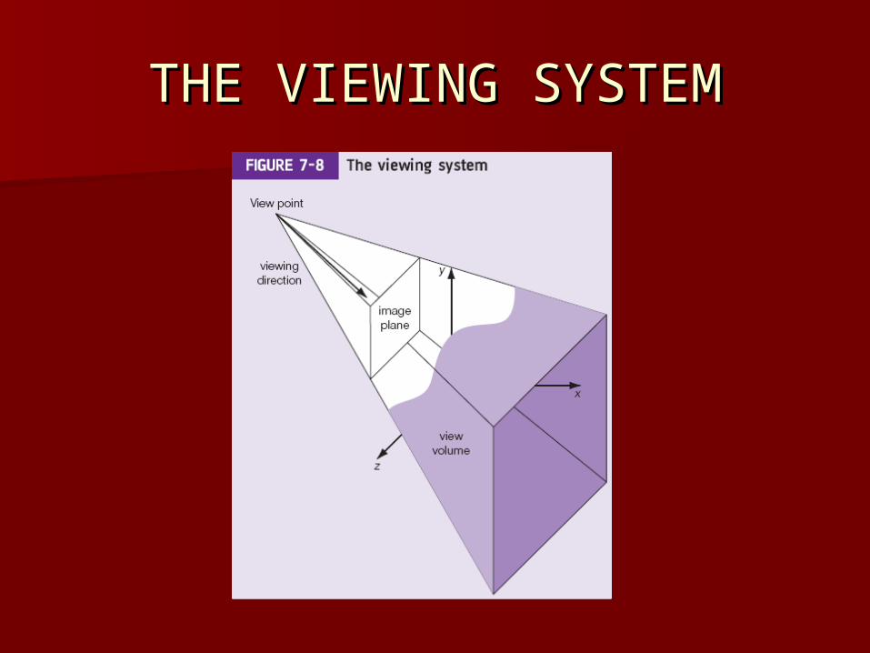
The point of view can either be the origin of the coordinate system, or the center of projection.
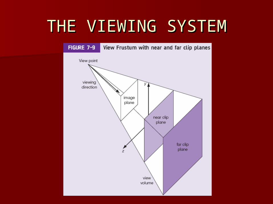
The viewing system must also contain an image plane for the projection of scenes and a view frustum/volume for the specification of the field of view.
THE VIEWING SYSTEMTHE VIEWING SYSTEM
THE VIEWING SYSTEMTHE VIEWING SYSTEM
The View Volume– a semi-infinite, truncated pyramid defined by
an image plane window and a near and far clipping plane.
Culling– also known as back-face elimination, removes
polygons hidden from the viewer. Clipping
– an optimization operation responsible for the display of only visible objects.
THE VIEWING SYSTEMTHE VIEWING SYSTEM

CHANGING COORDINATE CHANGING COORDINATE SYSTEMSSYSTEMS
It’s often necessary to define geometry in terms of a coordinate system innately fitting the representation of a model.
Such a coordinate system is referred to as the object or model frame (also known as model space) where vertices are defined relative to the modeling coordinate system’s origin.
CHANGING COORDINATE CHANGING COORDINATE SYSTEMSSYSTEMS
This model frame must be converted to the world frame (all vertices are defined relative to a mutual origin) for proper model representation.
Once we’ve converted the model frame to the world frame we still have no idea how these models would appear to the camera.

CHANGING COORDINATE CHANGING COORDINATE SYSTEMSSYSTEMS
To accomplish this we need to change the coordinate system from the world frame to the camera or view frame with the viewer at the origin of the camera’s lens looking in the positive z-direction.
This switch in coordinate systems is accomplished with the world and view matrices via the viewing transformation for Direct3D and the modelview matrix for OpenGL.

CHANGING COORDINATE CHANGING COORDINATE SYSTEMSSYSTEMS
Viewing Transformation
Modeling Transformation
Projection Transformation
Viewport Transformation

SPATIAL SPATIAL TRANSFORMATIONSTRANSFORMATIONS
Here Here we focus on three-dimensional transformations such as rotation, scaling, and translation.
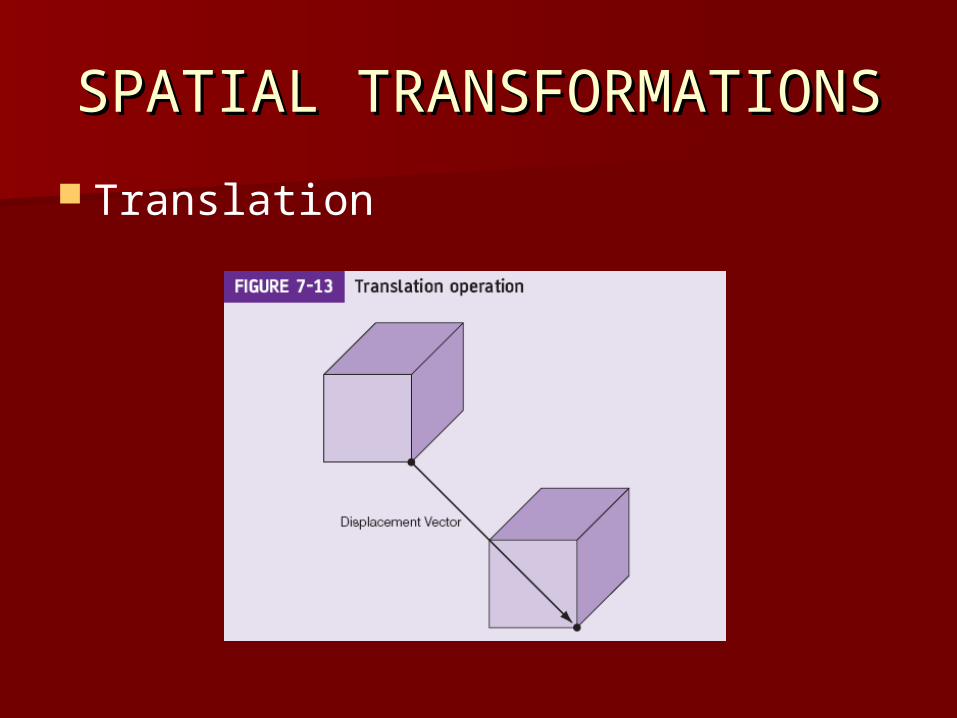
A transformation is an operation that moves a vertex or vector from one point in space to another.
These transformations are denoted by a matrix with several matrices often combined for a custom transformation.
Affine transformation is simply a term used to describe a sequence of linear transformations (rotation, scaling, etc.) followed by a translation operation.
A linear transformation or linear map is a function that maps objects (vertices and vectors) from one vector space to another.
SPATIAL SPATIAL TRANSFORMATIONSTRANSFORMATIONS
Translation
SPATIAL SPATIAL TRANSFORMATIONSTRANSFORMATIONS
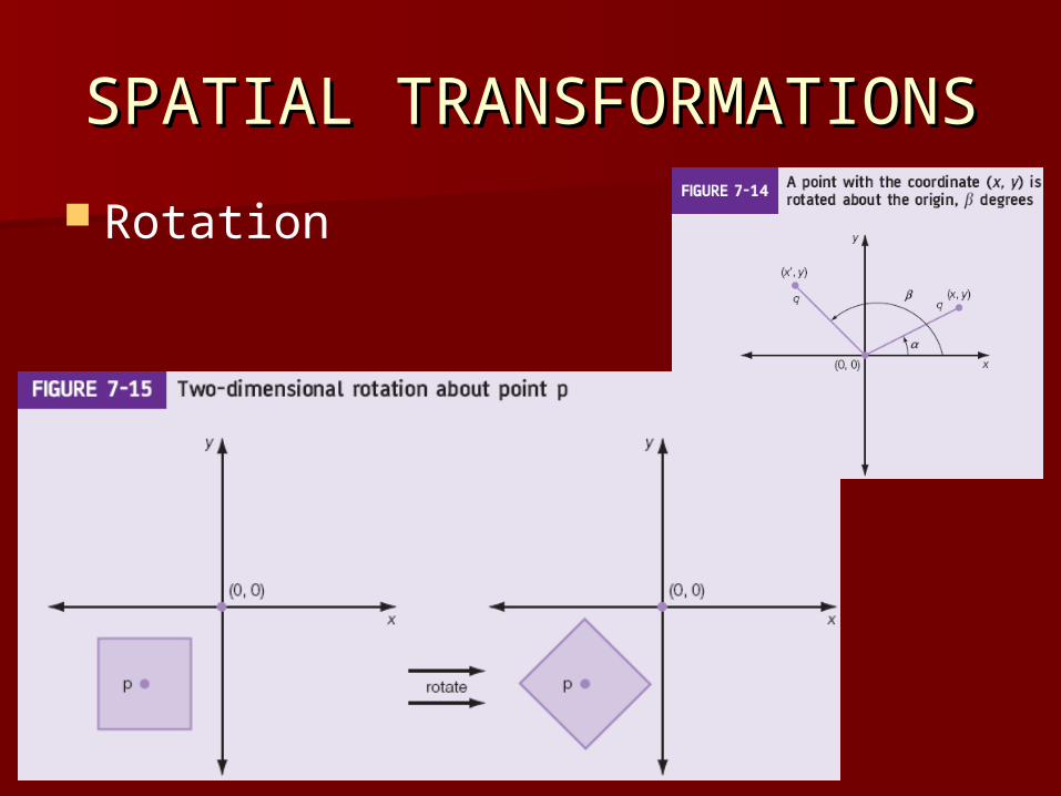
Rotation
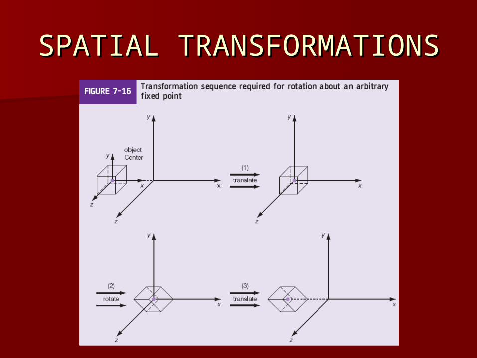
SPATIAL SPATIAL TRANSFORMATIONSTRANSFORMATIONS
SPATIAL SPATIAL TRANSFORMATIONSTRANSFORMATIONS
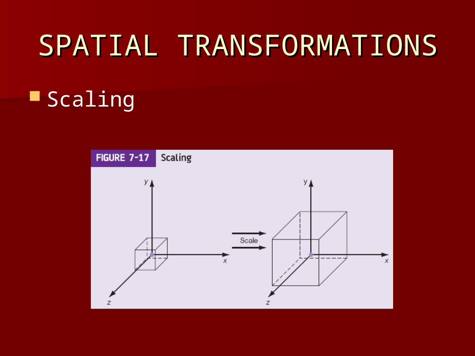
Scaling
ExamplesExamples
Rendering a triangle without any transformations– [see the textbook and source code
“BasicTriangle (Direct3D)” on the book’s website for a detailed example].
ExamplesExamples
Rendering a triangle translated– [see the textbook and source code
“BasicTriangleTranslated (Direct3D)” on the book’s website for a detailed example].
ExamplesExamples
Rendering a triangle rotated– [see the textbook and source code
“BasicTriangleRotated (Direct3D)” on the book’s website for a detailed example].
ExamplesExamples
Rendering a scaled triangle– [see the textbook and source code
“BasicTriangleScaled (Direct3D)” on the book’s website for a detailed example].

ExamplesExamples
Working with OpenGL: Translation, Rotation and Scaling– [see the textbook and source code
“Translation, Rotation and Scaling (OpenGL)” on the book’s website for a detailed example].