chapter 8. material-removal processes: cuttingocw.snu.ac.kr/sites/default/files/note/8029.pdf ·...
TRANSCRIPT
4 4 6 . 3 0 5 A M A N U F A C T U R I N G P R O C E S S E S
Chapter 8. Material-Removal Processes: CuttingProcesses: Cutting
Sung-Hoon AhnSchool of Mechanical and Aerospace Engineering
Seoul National University
2
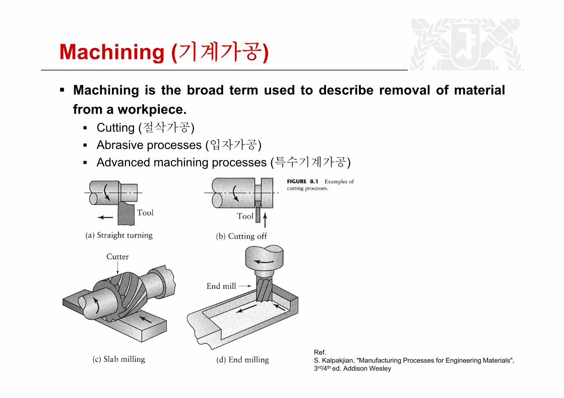
Machining (기계가공)g ( )Machining is the broad term used to describe removal of materialfrom a workpiecefrom a workpiece.
Cutting (절삭가공)Abrasive processes (입자가공)Advanced machining processes (특수기계가공)
Ref.S. Kalpakjian, "Manufacturing Processes for Engineering Materials",3rd/4th ed. Addison Wesley
3
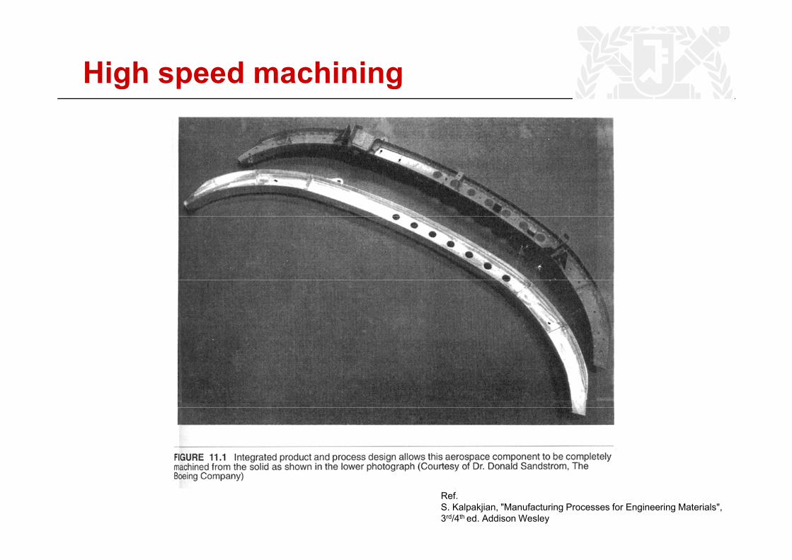
High speed machining
Ref.S. Kalpakjian, "Manufacturing Processes for Engineering Materials",3rd/4th ed. Addison Wesley
4
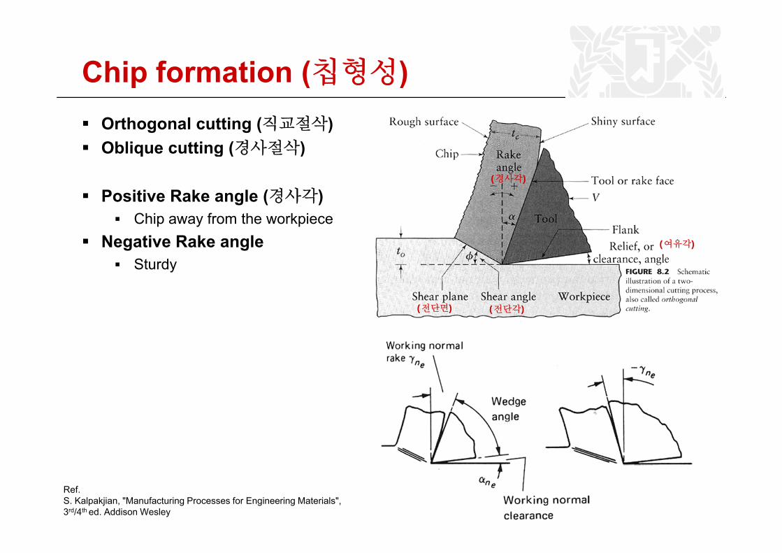
Chip formation (칩형성)( )Orthogonal cutting (직교절삭)Oblique cutting (경사절삭)Oblique cutting (경사절삭)
Positive Rake angle (경사각)Chi f th k i
(경사각)
Chip away from the workpieceNegative Rake angle
Sturdy(여유각)
(전단면) (전단각)
Ref.S. Kalpakjian, "Manufacturing Processes for Engineering Materials",3rd/4th ed. Addison Wesley
5
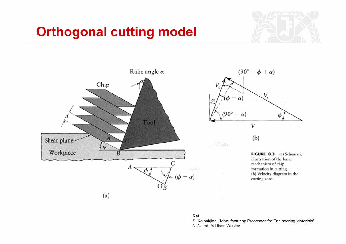
Orthogonal cutting model
Ref.S. Kalpakjian, "Manufacturing Processes for Engineering Materials",3rd/4th ed. Addison Wesley
6
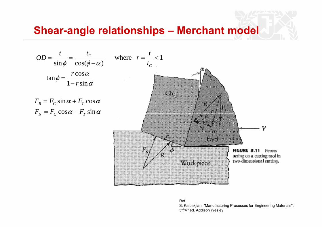
Shear-angle relationships – Merchant model
φφ )(ittOD C== 1 where <=
ttr
ααφ
αφφ
sin1costan
)cos(sin
rr−
=
− Ct
αααα
sincoscossin
TCN
TCR
FFFFFF−=+=
αα sincos TCN FFF
Ref.S. Kalpakjian, "Manufacturing Processes for Engineering Materials",3rd/4th ed. Addison Wesley
7
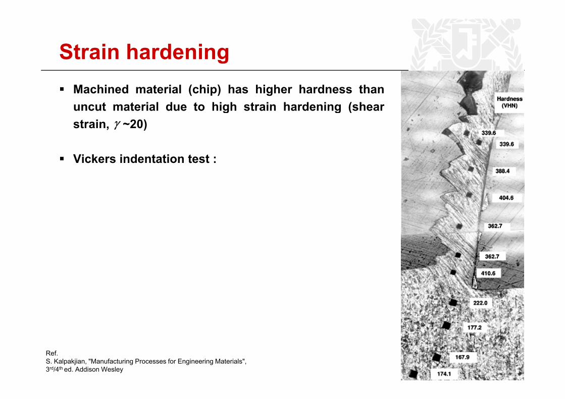
Strain hardeningMachined material (chip) has higher hardness thanuncut material due to high strain hardening (shearuncut material due to high strain hardening (shearstrain, ~20)
Vi k i d i
γ
Vickers indentation test :
Ref.S. Kalpakjian, "Manufacturing Processes for Engineering Materials",3rd/4th ed. Addison Wesley
8
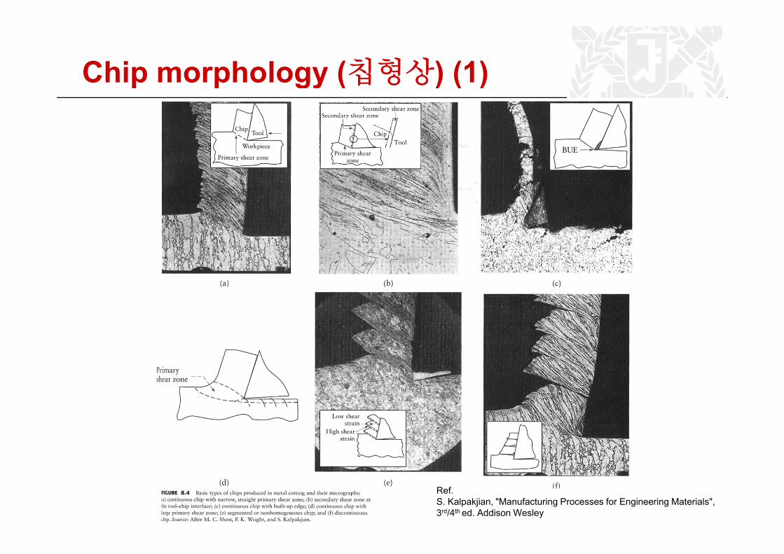
Chip morphology (칩형상) (1)gy ( ) ( )
Ref.S. Kalpakjian, "Manufacturing Processes for Engineering Materials",3rd/4th ed. Addison Wesley
9
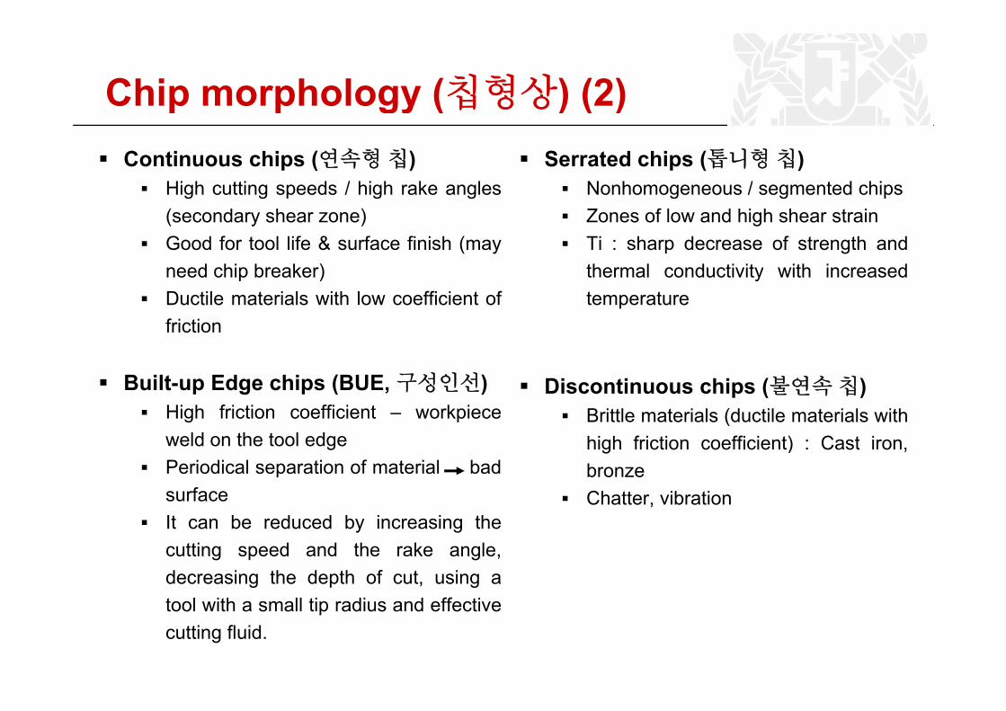
Chip morphology (칩형상) (2)Continuous chips (연속형칩)
High cutting speeds / high rake angles
gy ( ) ( )Serrated chips (톱니형칩)
Nonhomogeneous / segmented chipsHigh cutting speeds / high rake angles(secondary shear zone)Good for tool life & surface finish (mayneed chip breaker)
Nonhomogeneous / segmented chipsZones of low and high shear strainTi : sharp decrease of strength andthermal conductivity with increasedneed chip breaker)
Ductile materials with low coefficient offriction
thermal conductivity with increasedtemperature
Built-up Edge chips (BUE,구성인선)High friction coefficient – workpieceweld on the tool edge
Discontinuous chips (불연속칩)Brittle materials (ductile materials withhi h f i ti ffi i t) C t iweld on the tool edge
Periodical separation of material badsurfaceIt b d d b i i th
high friction coefficient) : Cast iron,bronzeChatter, vibration
It can be reduced by increasing thecutting speed and the rake angle,decreasing the depth of cut, using a
l i h ll i di d ff itool with a small tip radius and effectivecutting fluid.
10
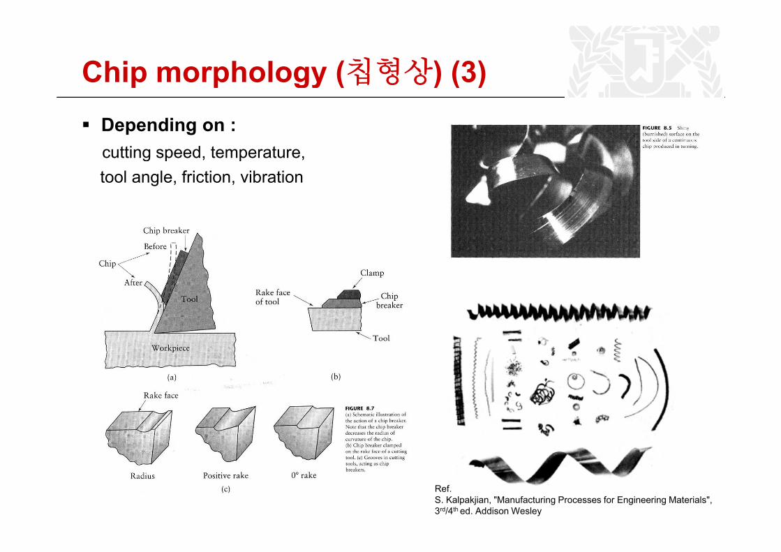
Chip morphology (칩형상) (3)gy ( ) ( )Depending on :cutting speed temperaturecutting speed, temperature,tool angle, friction, vibration
Ref.S. Kalpakjian, "Manufacturing Processes for Engineering Materials",3rd/4th ed. Addison Wesley
11
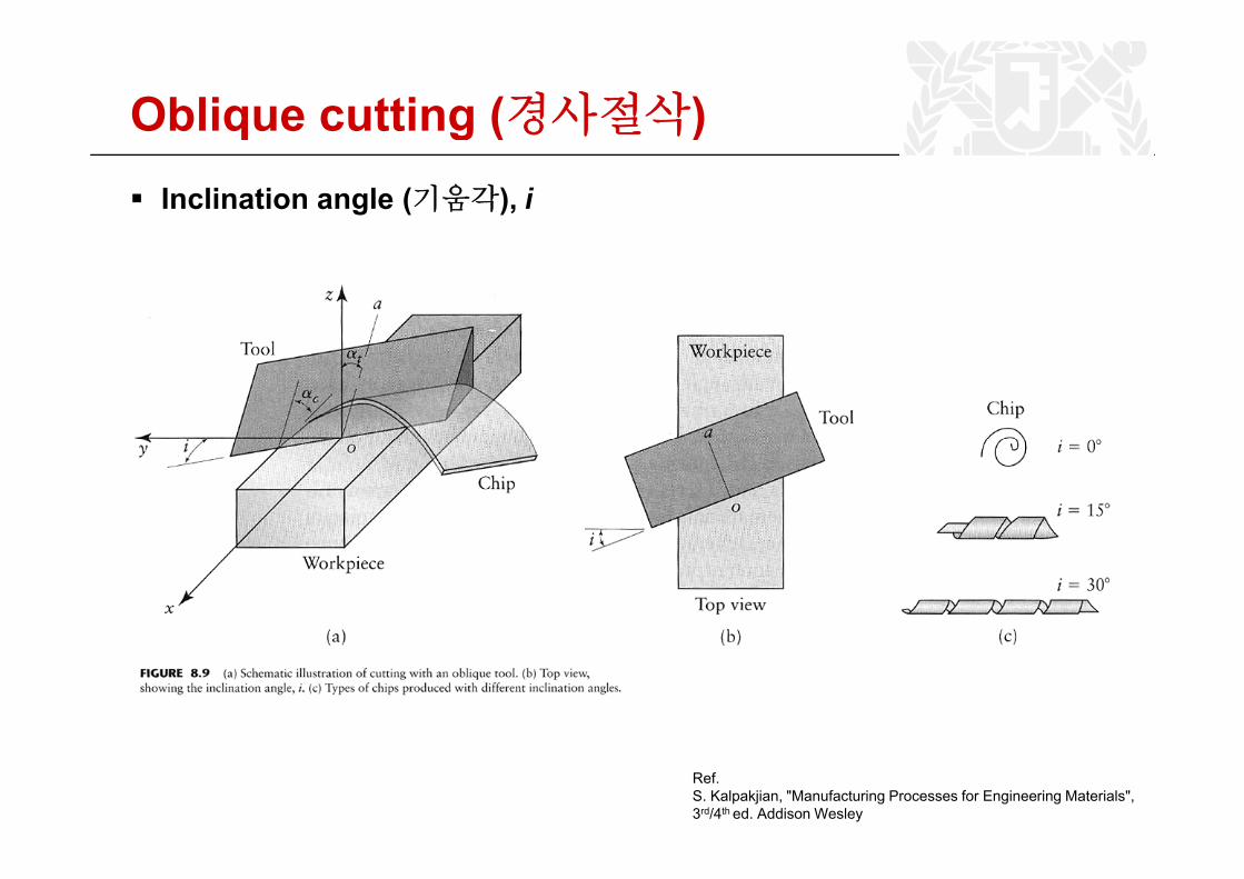
Oblique cutting (경사절삭)g ( )Inclination angle (기움각), i
Ref.S. Kalpakjian, "Manufacturing Processes for Engineering Materials",3rd/4th ed. Addison Wesley
12
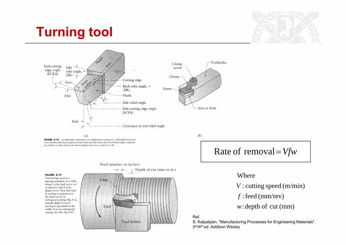
Turning tool
VfwremovalofRate
Where
VfwremovalofRate =
(mm)cutofdepth:(mm/rev) feed :
(m/min) speed cutting:
wf
V
Ref.S. Kalpakjian, "Manufacturing Processes for Engineering Materials",3rd/4th ed. Addison Wesley
(mm)cut ofdepth :w
13
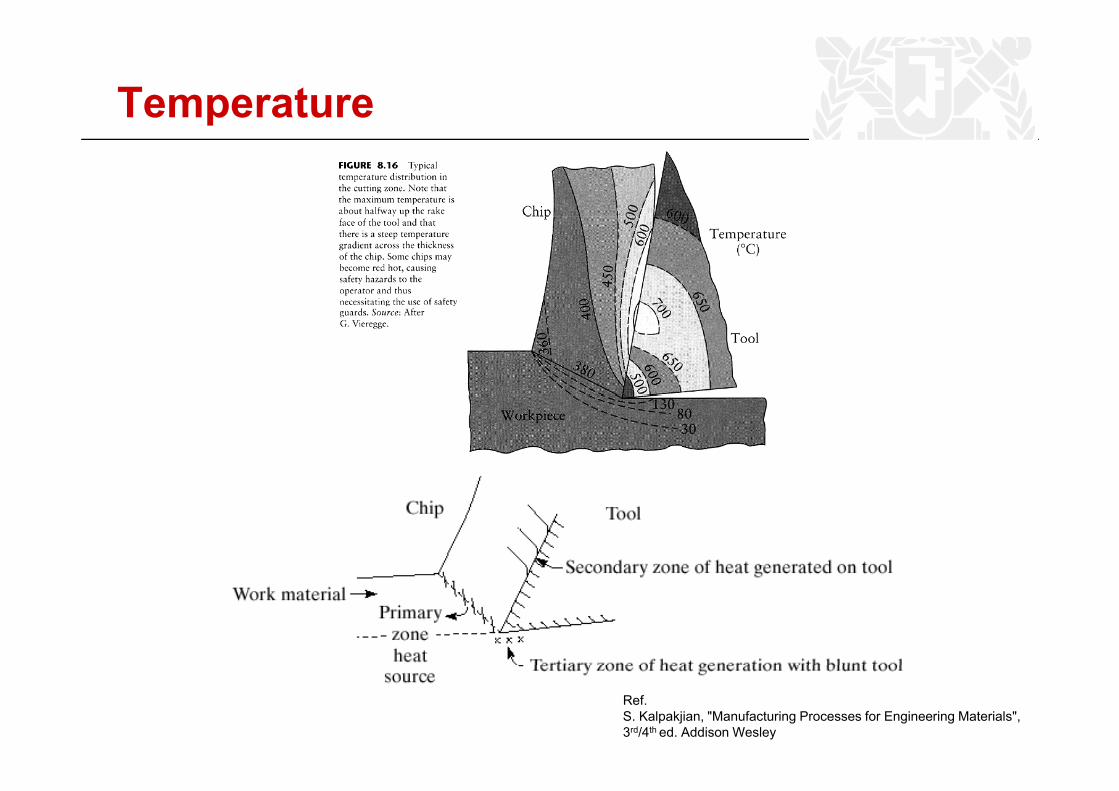
Temperature
Ref.S. Kalpakjian, "Manufacturing Processes for Engineering Materials",3rd/4th ed. Addison Wesley
14
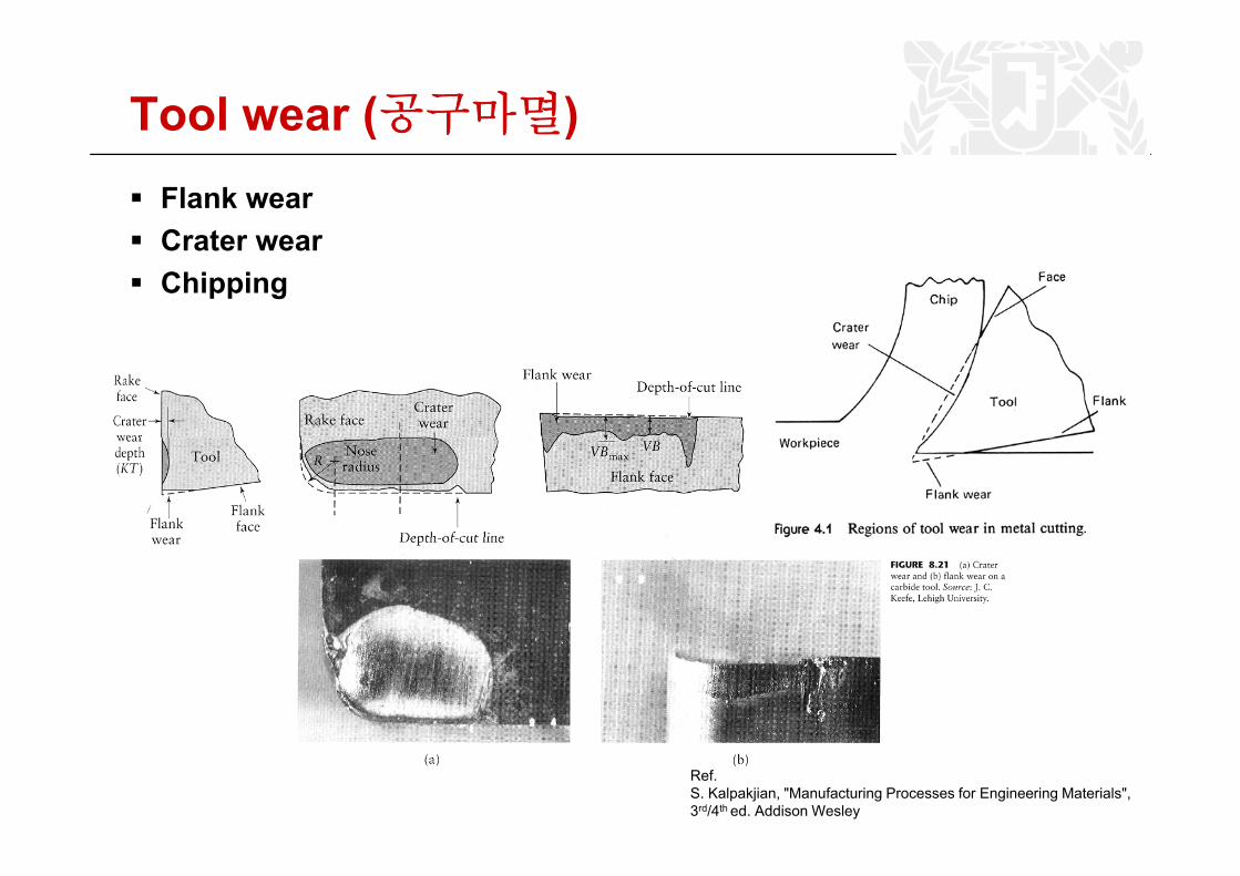
Tool wear (공구마멸)( )Flank wearCrater wearCrater wearChipping
Ref.S. Kalpakjian, "Manufacturing Processes for Engineering Materials",3rd/4th ed. Addison Wesley
15
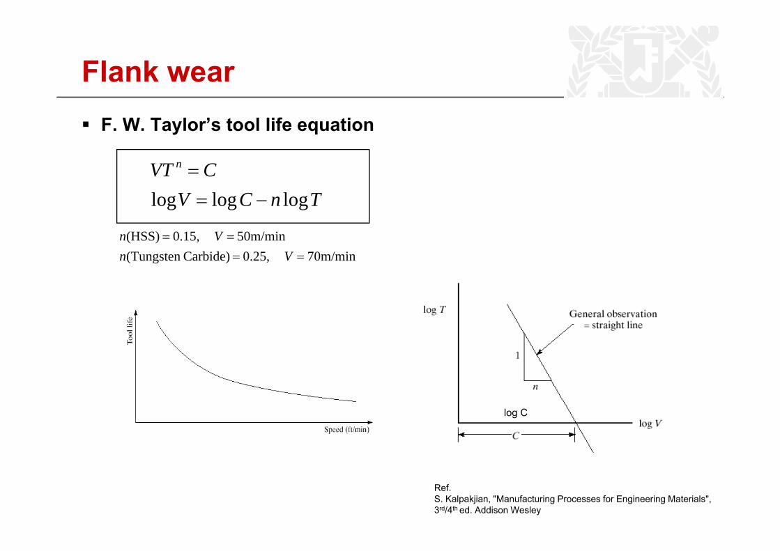
Flank wearF. W. Taylor’s tool life equation
TnCVCVT n
logloglog −==
70m/min 0.25,Carbide)(Tungsten 50m/min 0.15,(HSS)
====
VnVn
log C
Ref.S. Kalpakjian, "Manufacturing Processes for Engineering Materials",3rd/4th ed. Addison Wesley
16
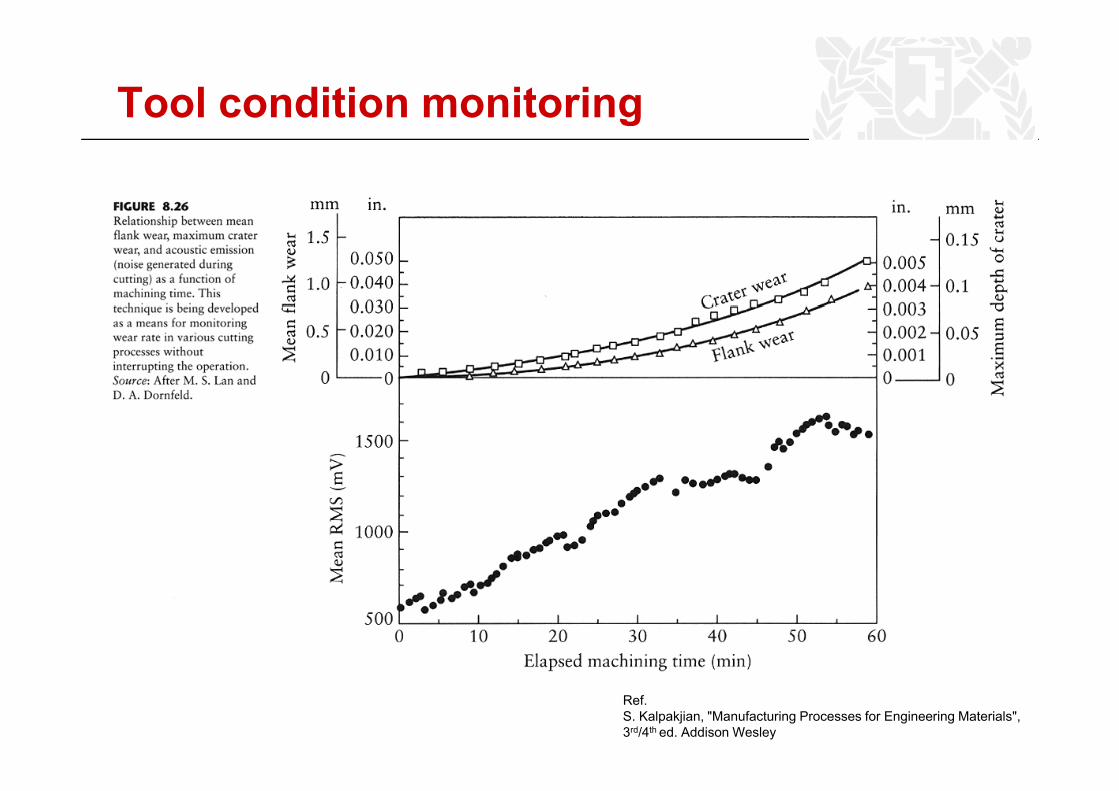
Tool condition monitoring
Ref.S. Kalpakjian, "Manufacturing Processes for Engineering Materials",3rd/4th ed. Addison Wesley
17
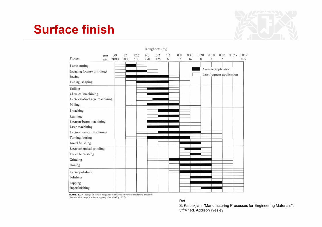
Surface finish
Ref.S. Kalpakjian, "Manufacturing Processes for Engineering Materials",3rd/4th ed. Addison Wesley
18
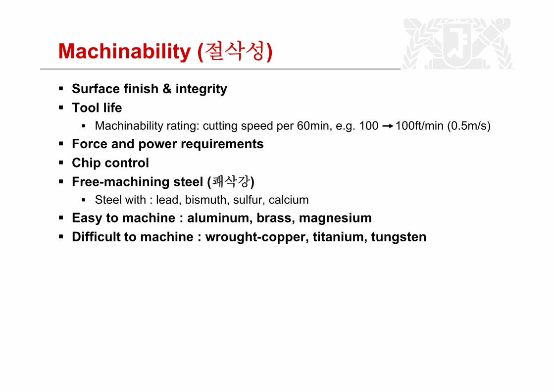
Machinability (절삭성)y ( )Surface finish & integrityTool lifeTool life
Machinability rating: cutting speed per 60min, e.g. 100 100ft/min (0.5m/s)Force and power requirementsChip controlFree-machining steel (쾌삭강)
St l ith l d bi th lf l iSteel with : lead, bismuth, sulfur, calciumEasy to machine : aluminum, brass, magnesiumDifficult to machine : wrought-copper, titanium, tungstenDifficult to machine : wrought copper, titanium, tungsten
19
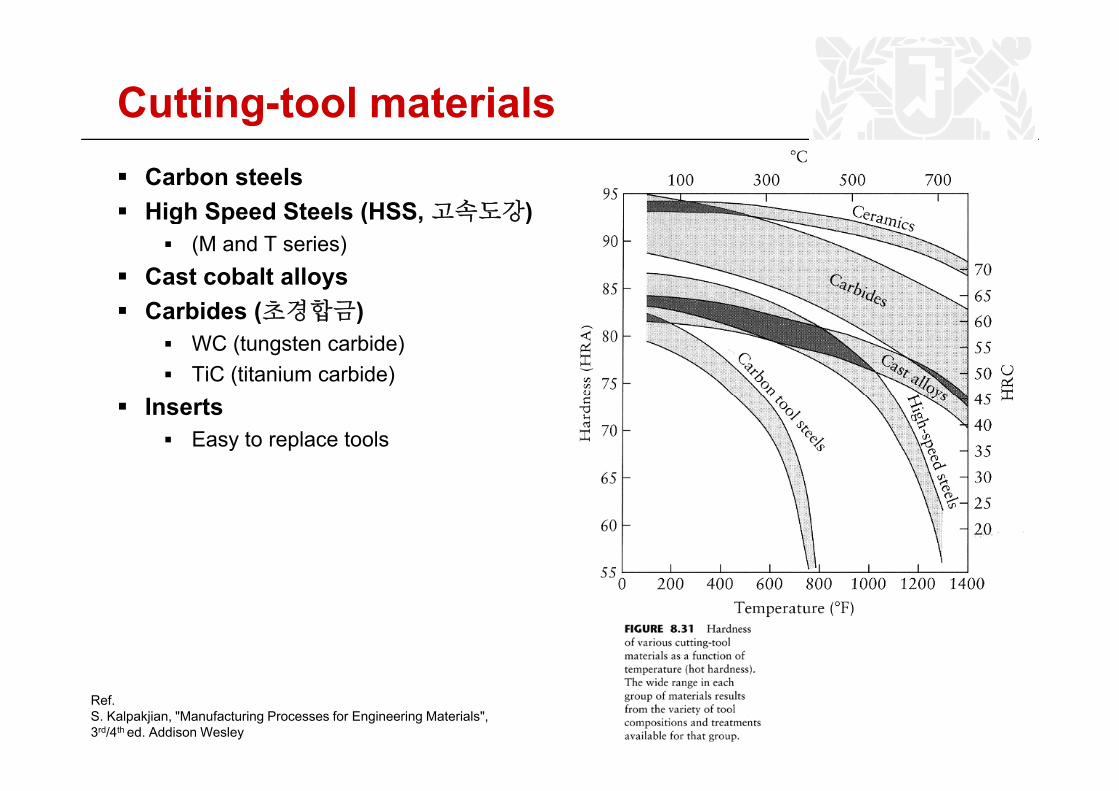
Cutting-tool materialsCarbon steelsHigh Speed Steels (HSS 고속도강)High Speed Steels (HSS,고속도강)
(M and T series)Cast cobalt alloysC bid (초경합금)Carbides (초경합금)
WC (tungsten carbide)TiC (titanium carbide)
InsertsEasy to replace tools
Ref.S. Kalpakjian, "Manufacturing Processes for Engineering Materials",3rd/4th ed. Addison Wesley
20
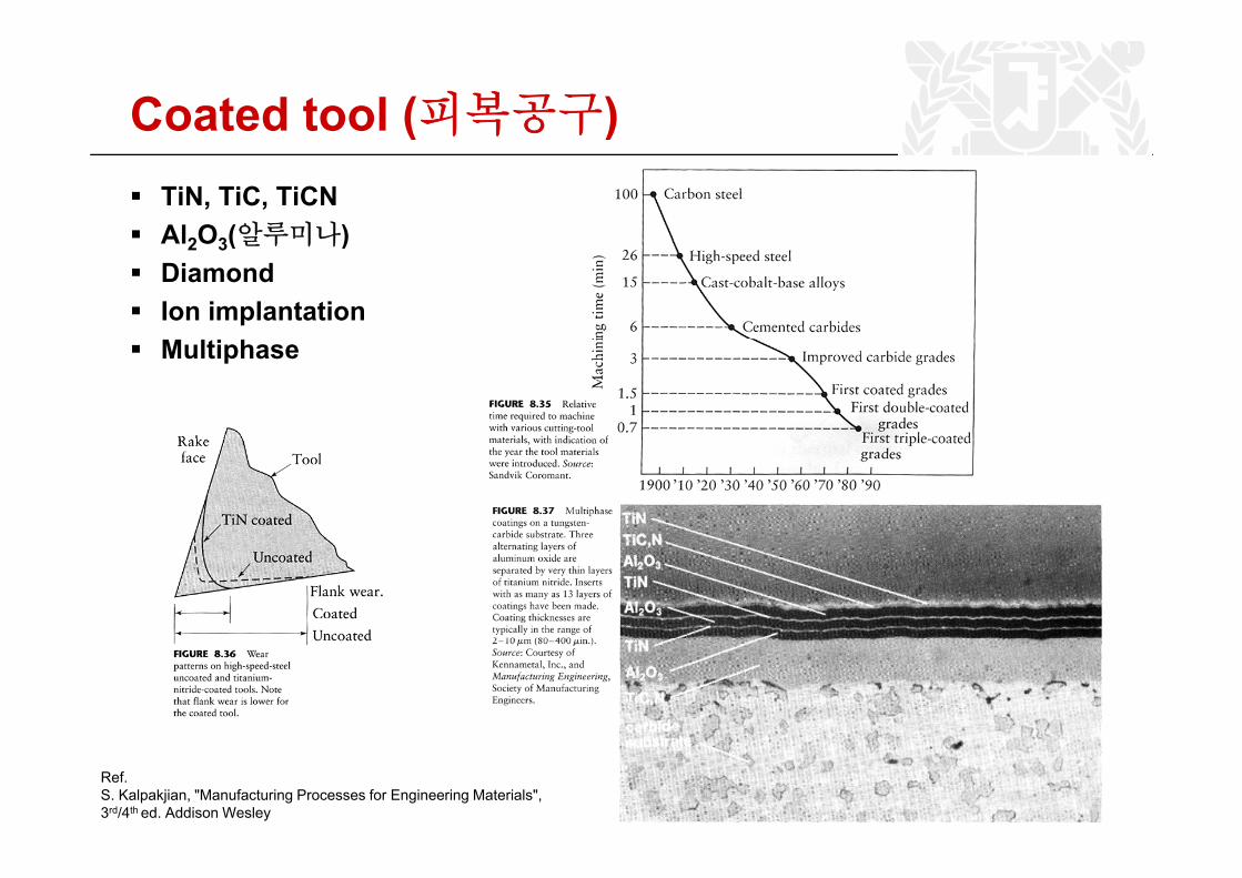
Coated tool (피복공구)( )TiN, TiC, TiCNAl2O3(알루미나)Al2O3(알루미나)DiamondIon implantationM l i hMultiphase
Ref.S. Kalpakjian, "Manufacturing Processes for Engineering Materials",3rd/4th ed. Addison Wesley
21
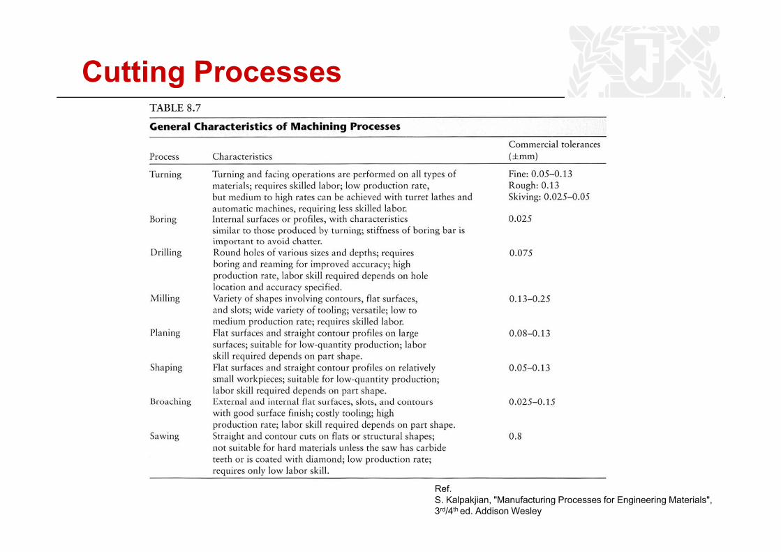
Cutting Processes
Ref.S. Kalpakjian, "Manufacturing Processes for Engineering Materials",3rd/4th ed. Addison Wesley
22
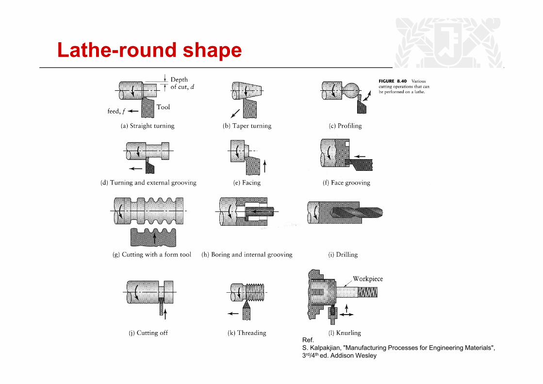
Lathe-round shape
Ref.S. Kalpakjian, "Manufacturing Processes for Engineering Materials",3rd/4th ed. Addison Wesley
23
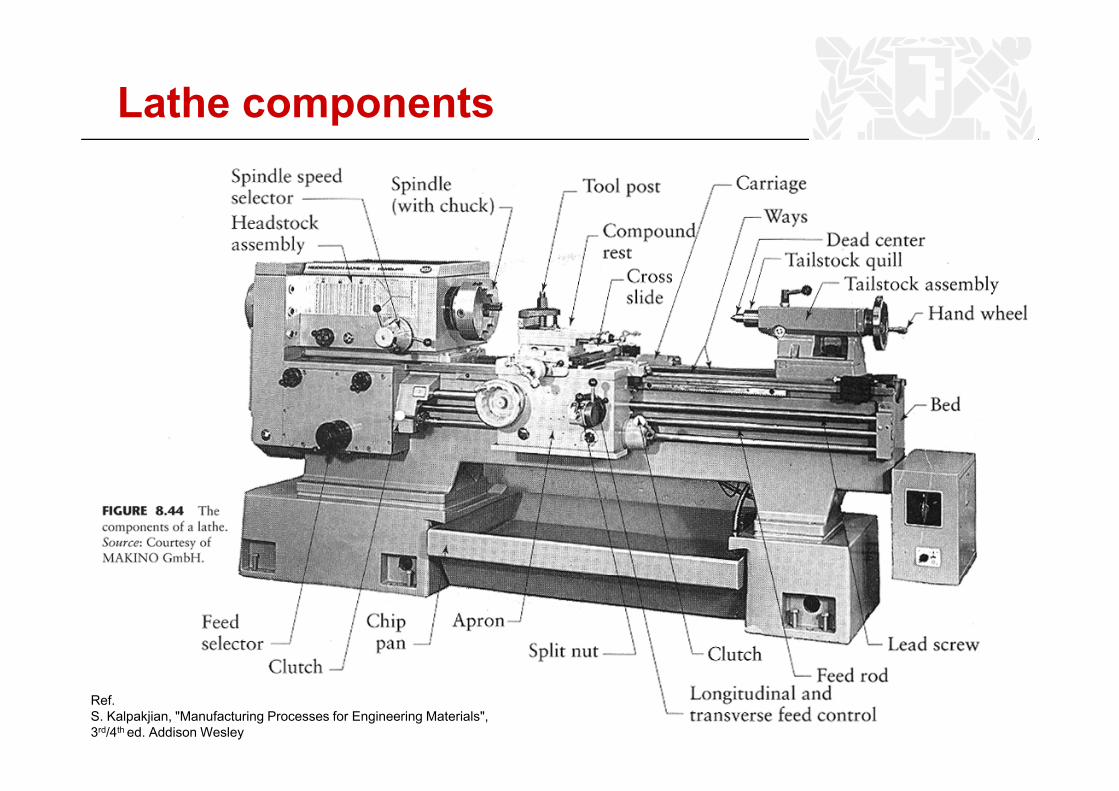
Lathe components
Ref.S. Kalpakjian, "Manufacturing Processes for Engineering Materials",3rd/4th ed. Addison Wesley
24
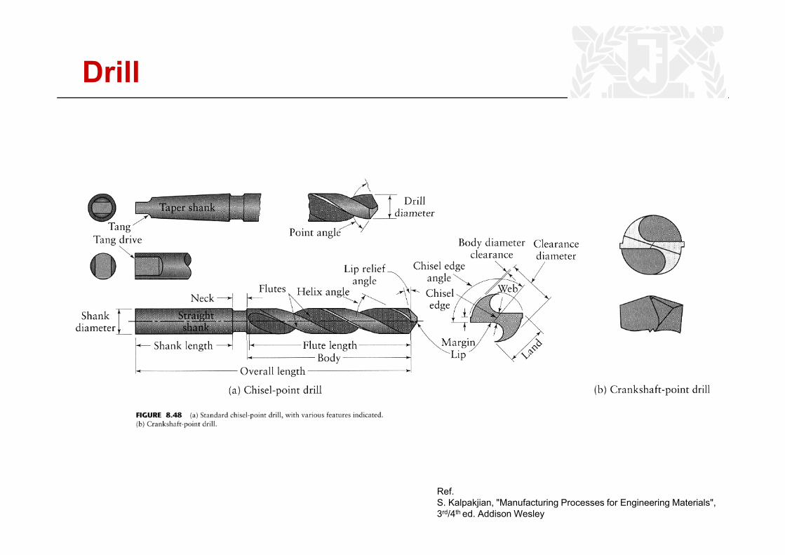
Drill
Ref.S. Kalpakjian, "Manufacturing Processes for Engineering Materials",3rd/4th ed. Addison Wesley
25
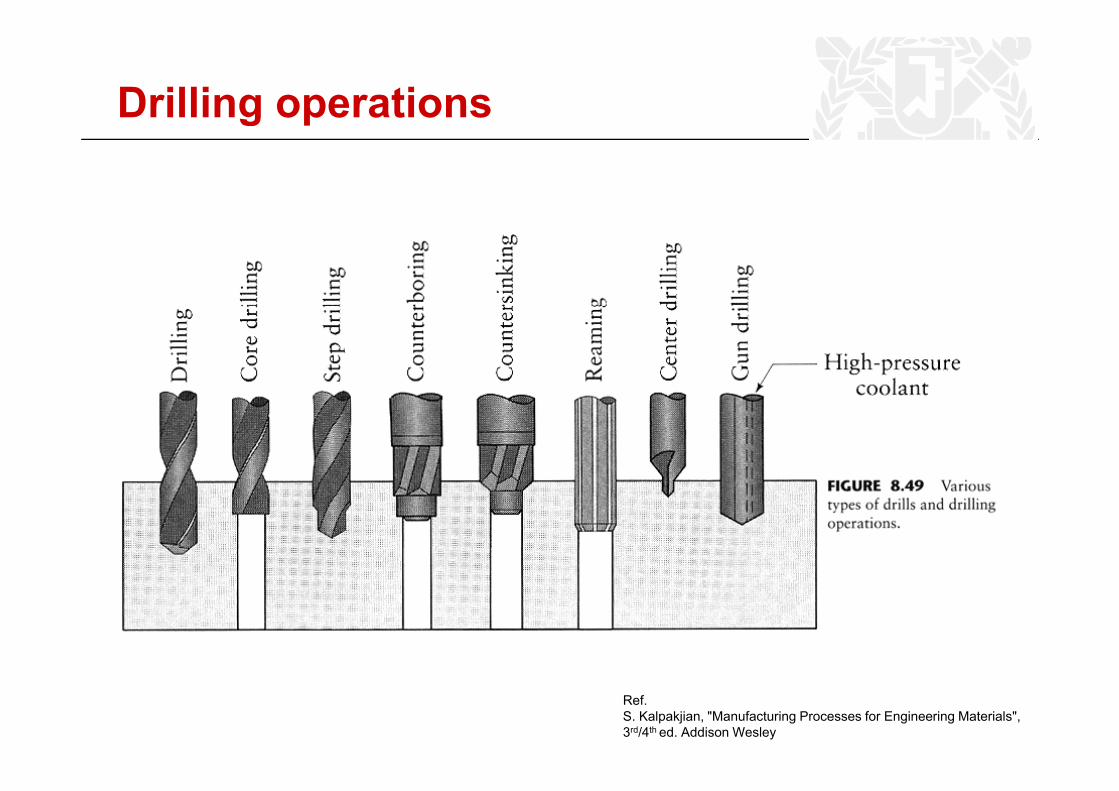
Drilling operations
Ref.S. Kalpakjian, "Manufacturing Processes for Engineering Materials",3rd/4th ed. Addison Wesley
26
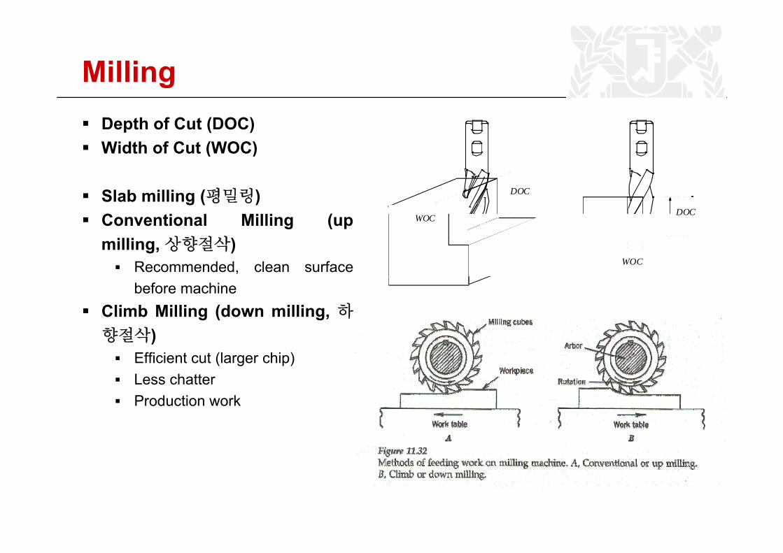
MillingDepth of Cut (DOC)Width of Cut (WOC)
DOC
DOC
Width of Cut (WOC)
Slab milling (평밀링)C i l Milli ( DOC
WOC
WOCConventional Milling (upmilling,상향절삭)
Recommended, clean surfacebefore machine
Climb Milling (down milling, 하향절삭)향절삭)
Efficient cut (larger chip)Less chatterProduction workProduction work
27
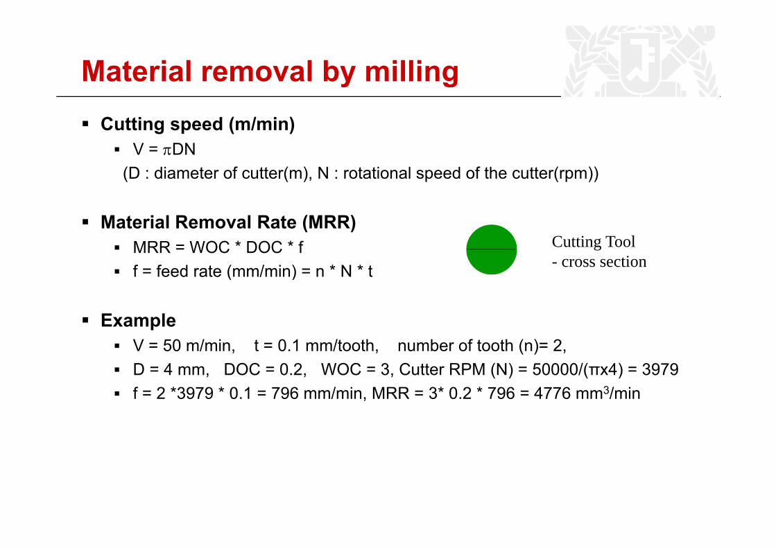
Material removal by millingCutting speed (m/min)
V = πDNV = πDN(D : diameter of cutter(m), N : rotational speed of the cutter(rpm))
Material Removal Rate (MRR)MRR = WOC * DOC * ff = feed rate (mm/min) = n * N * t
Cutting Tool - cross sectionf feed rate (mm/min) n N t
ExampleV = 50 m/min, t = 0.1 mm/tooth, number of tooth (n)= 2,D = 4 mm, DOC = 0.2, WOC = 3, Cutter RPM (N) = 50000/(πx4) = 3979f = 2 *3979 * 0.1 = 796 mm/min, MRR = 3* 0.2 * 796 = 4776 mm3/minf 2 3979 0.1 796 mm/min, MRR 3 0.2 796 4776 mm /min
28
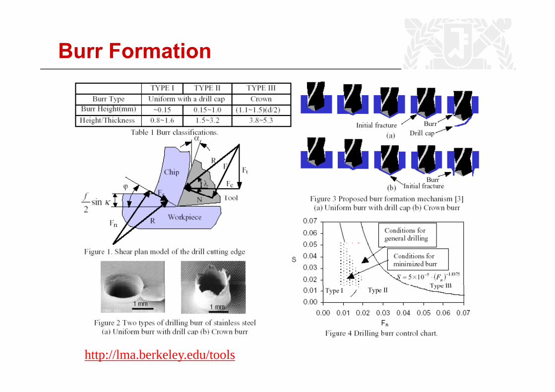
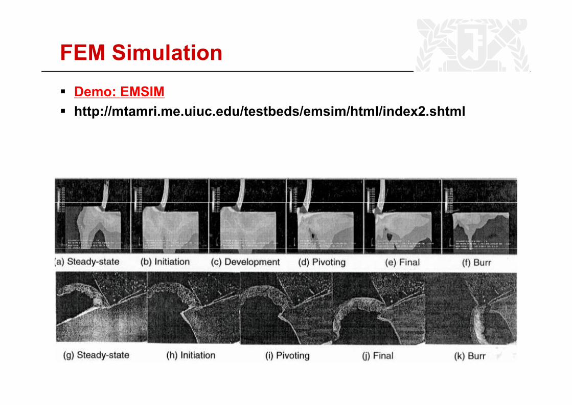
Burr Formation
http://lma.berkeley.edu/tools
29
FEM SimulationDemo: EMSIMhttp://mtamri me uiuc edu/testbeds/emsim/html/index2 shtmlhttp://mtamri.me.uiuc.edu/testbeds/emsim/html/index2.shtml
30
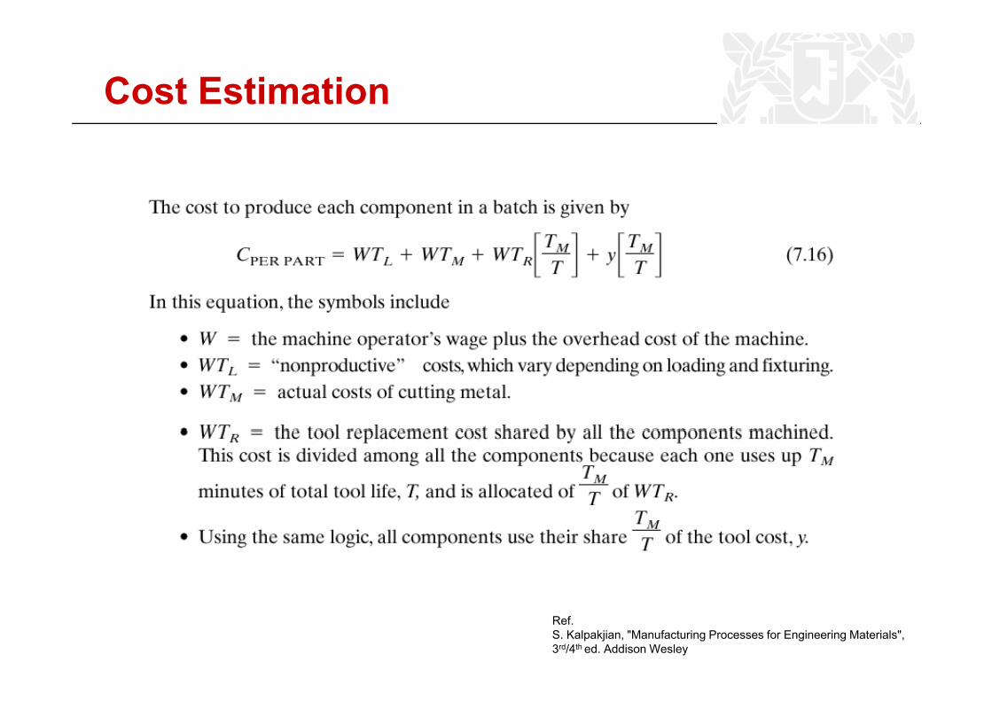
Cost Estimation
Ref.S. Kalpakjian, "Manufacturing Processes for Engineering Materials",3rd/4th ed. Addison Wesley
31
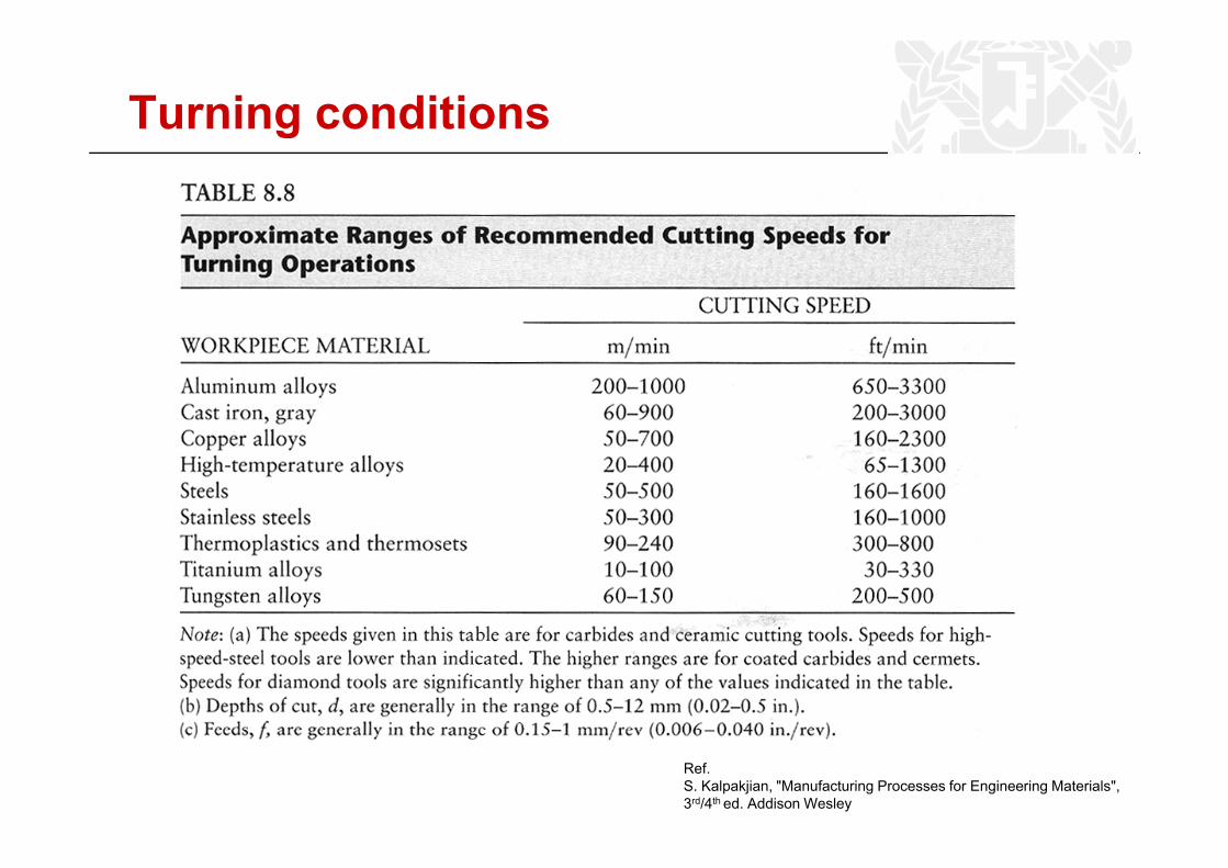
Turning conditions
Ref.S. Kalpakjian, "Manufacturing Processes for Engineering Materials",3rd/4th ed. Addison Wesley
32
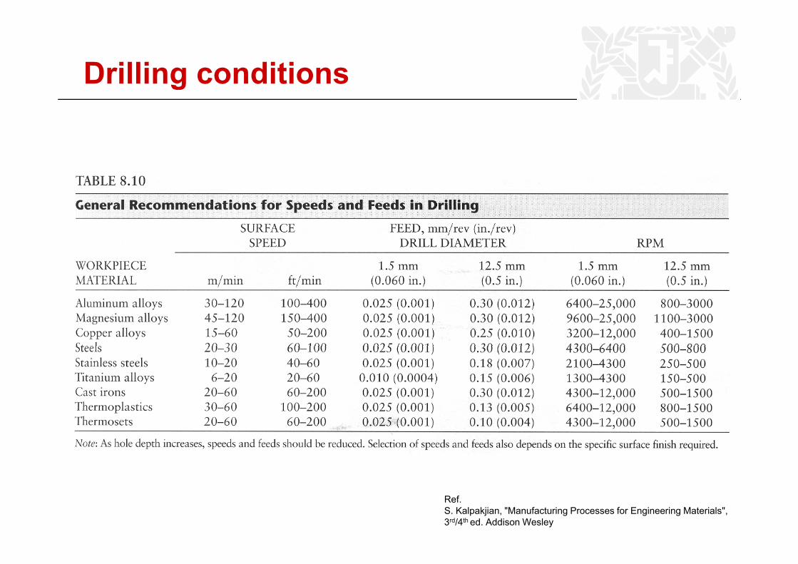
Drilling conditions
Ref.S. Kalpakjian, "Manufacturing Processes for Engineering Materials",3rd/4th ed. Addison Wesley
33
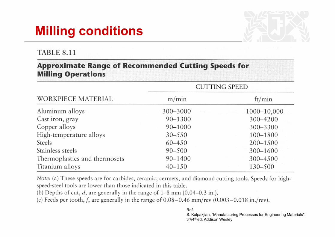
Milling conditions
Ref.S. Kalpakjian, "Manufacturing Processes for Engineering Materials",3rd/4th ed. Addison Wesley
34
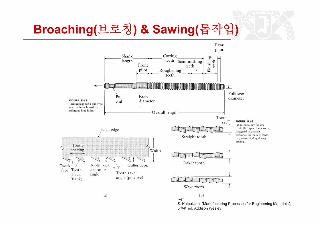
Broaching(브로칭) & Sawing(톱작업)g( ) g( )
Ref.S. Kalpakjian, "Manufacturing Processes for Engineering Materials",3rd/4th ed. Addison Wesley
35
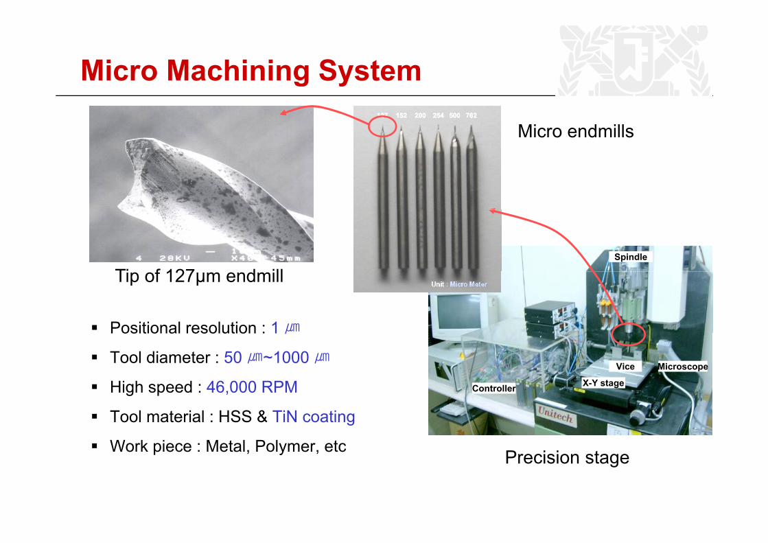
Micro Machining System
Micro endmills
Spindle
Ti f 127 d ill Main computerTip of 127μm endmill
Positional resolution : 1 ㎛
Controller
Microscope
X-Y stage
Vice
Positional resolution : 1 ㎛
Tool diameter : 50 ㎛~1000 ㎛
High speed : 46,000 RPMg p ,
Tool material : HSS & TiN coating
Work piece : Metal, Polymer, etc Precision stagePrecision stage
36
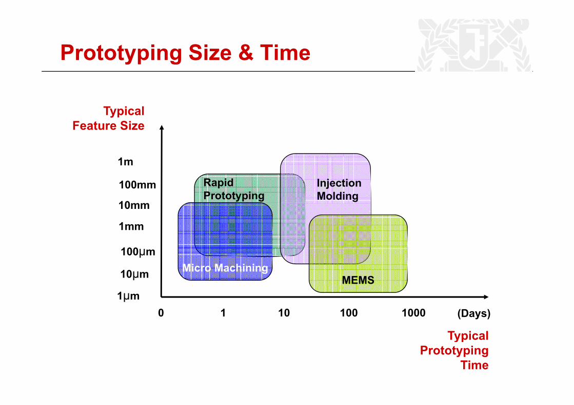
Prototyping Size & Time
TypicalTypicalFeature Size
RapidPrototyping
InjectionMolding
1m
10
100mm
1mm
100
10mm
1μmMEMS
Micro Machining10μm
100μm
1
Typical
0 10 100 1000 (Days)1μm
ypPrototyping
Time
37
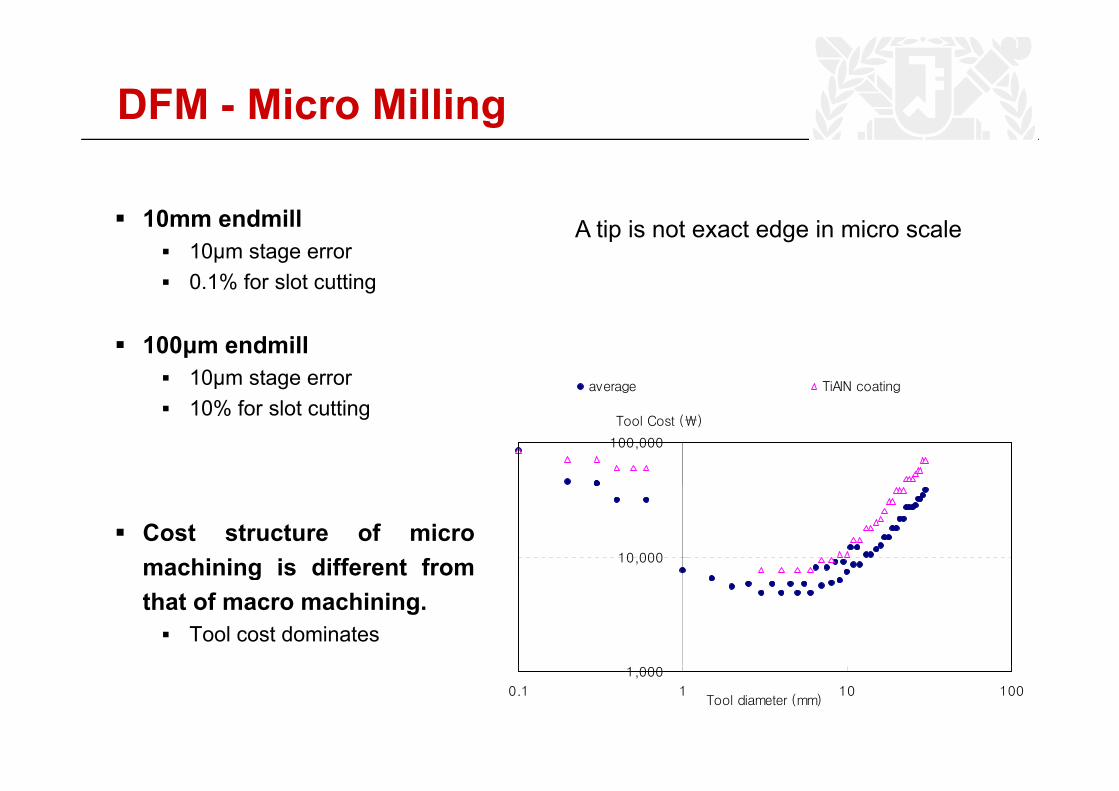
DFM - Micro Millingg
10mm endmill10mm endmill10μm stage error0.1% for slot cutting
A tip is not exact edge in micro scale
average TiAlN coating
100μm endmill10μm stage error
100,000
Tool Cost (₩)10% for slot cutting
10,000
Cost structure of micromachining is different frommachining is different fromthat of macro machining.
Tool cost dominates1,000
0.1 1 10 100Tool diameter (mm)

38
Spindle run-outRun-out effect on the final geometry is critical in micro machiningTotal run out = TIR (Total Indicator Reading) + Error TermsTotal run-out = TIR (Total Indicator Reading) + Error Terms (vibration, thermal deformation, etc)
10
5
6
7
8
9
t (㎛
)
100㎛
200㎛
1
2
3
4
5
Run
-ou
< Concept of run-out >< Result of Total Indicator Reading (TIR) >
00 5 10 15 20 25
Tool length (mm)
< Total Indicator Reading (TIR) Measurement >
39
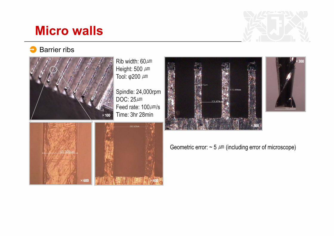
Micro wallsBarrier ribs
Rib width: 60㎛ ×300
Height: 500 ㎛Tool: φ200 ㎛
Spindle: 24 000rpmSpindle: 24,000rpmDOC: 25㎛Feed rate: 100㎛/sTime: 3hr 28min×100×10000
G i 5 (i l di f i )
×300
Geometric error: ~ 5 ㎛ (including error of microscope)
×1200 ×600×600 ×600
40
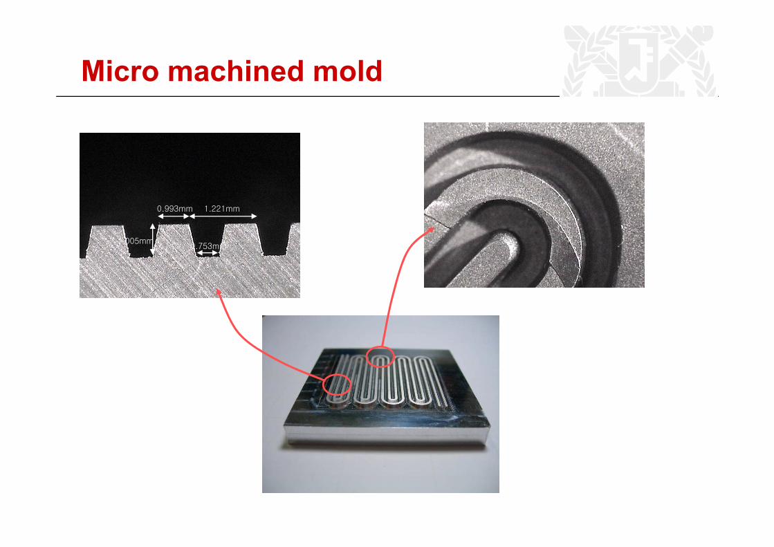
Micro machined mold
0.993mm 1.221mm
0.753mm
0.993mm
1.005mm
1.221mm
41
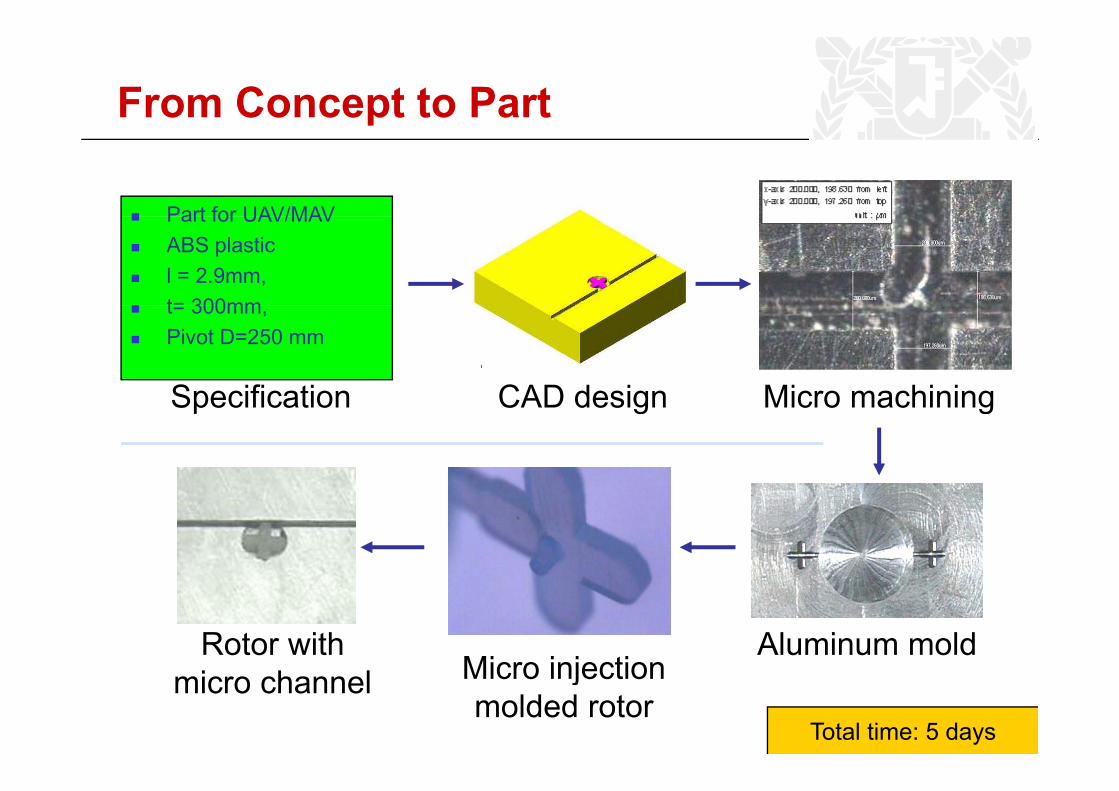
From Concept to Part
Part for UAV/MAVPart for UAV/MAVABS plasticl = 2.9mm, t= 300mm
CAD design Micro machining
t= 300mm, Pivot D=250 mm
Specification CAD design Micro machiningSpecification
Micro injectionRotor with Aluminum mold
Micro injection molded rotor
micro channelTotal time: 5 days
42
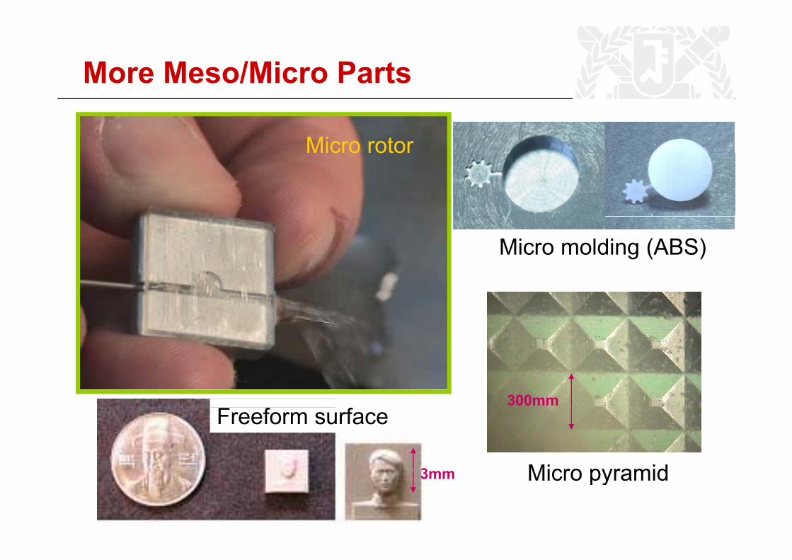
More Meso/Micro Parts
Micro rotorc o oto
Micro molding (ABS)
300mm
Micro pyramid
Freeform surface
3 Micro pyramid3mm
43
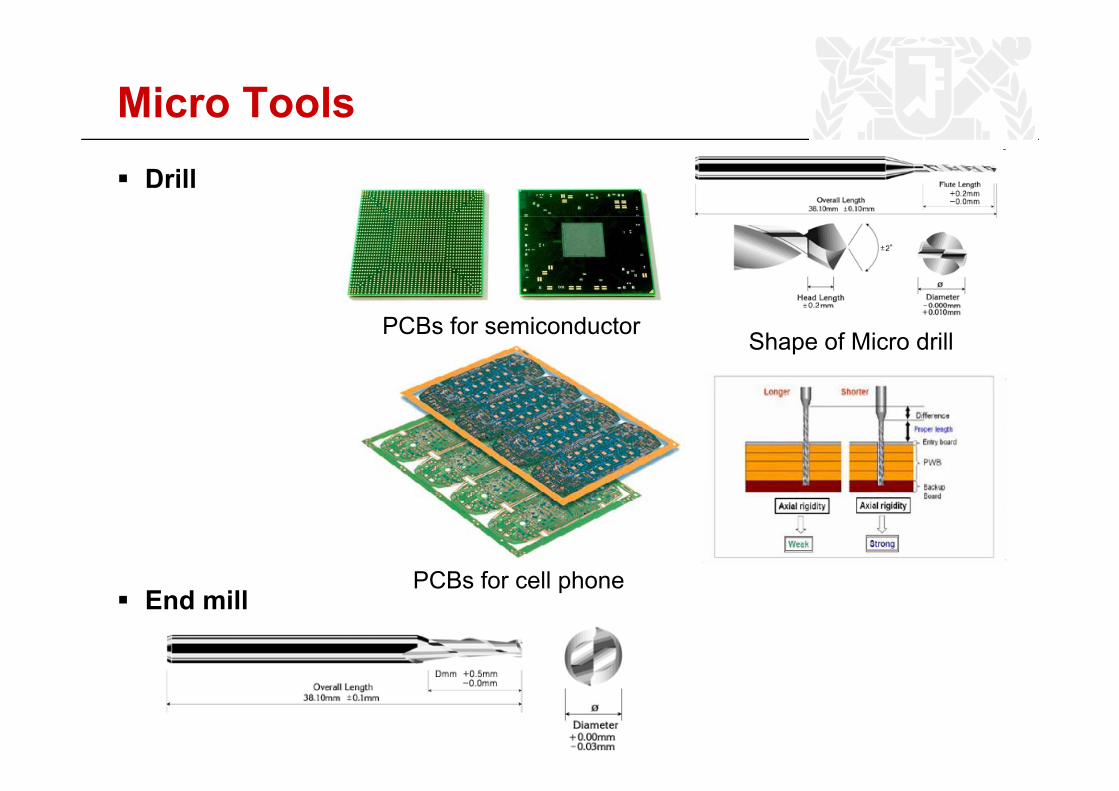
Micro ToolsDrill
PCBs for semiconductor Shape of Micro drill
PCB f ll hEnd mill
PCBs for cell phone
44
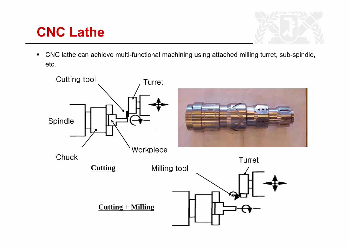
CNC LatheCNC lathe can achieve multi-functional machining using attached milling turret, sub-spindle,etc.
Cutting tool Turret
SpindleSpindle
WorkpieceChuck
Workpiece
Milling toolTurret
Cutting
Cutting + MillingCutting + Milling
45
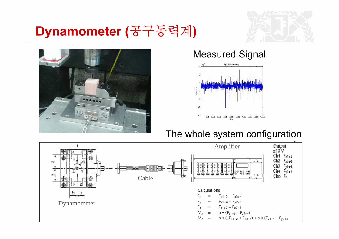
Dynamometer (공구동력계)y ( )Measured Signal
Amplifier
The whole system configurationAmplifier
Cable
Dynamometer