click to edit master title style - clsyzx.ujs.edu.cnclsyzx.ujs.edu.cn/fzsyfile/js/syjc/jc6.pdf ·...
TRANSCRIPT

1Copyright © ESI Group, 2006. All rights reserved.
微观组织设置教程
010-65544907ext243
曹栋良ESI中国
2Copyright © ESI Group, 2006. All rights reserved.
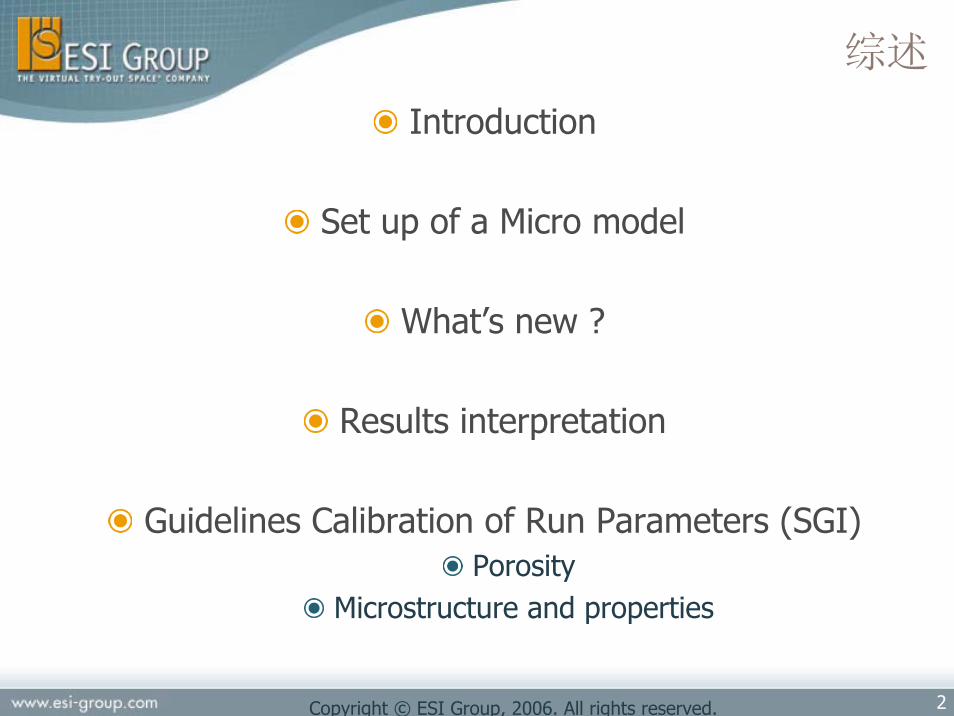
综述
Introduction
Set up of a Micro model
What’s new ?
Results interpretation
Guidelines Calibration of Run Parameters (SGI)Porosity
Microstructure and properties

3Copyright © ESI Group, 2006. All rights reserved.
介绍
Micro-模块可以计算得到基于合金的化学成分的各种微观组织结果,在凝固过程中能生成多种相
包括枝晶尺寸、枝晶间距和各种相的分数铸铁: 石墨化膨胀对缩松的影响机械性能
Fe-基: 布氏硬度其他基于设置的结果
与合金的计算材料热物性相关联
thermodynamic databases (Computherm)
4Copyright © ESI Group, 2006. All rights reserved.
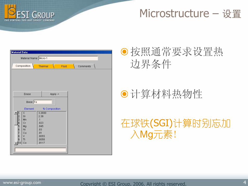
Microstructure – 设置
按照通常要求设置热边界条件
计算材料热物性
在球铁(SGI)计算时别忘加入Mg元素!

5Copyright © ESI Group, 2006. All rights reserved.
run parameter MICRO 设置成1
选择合金种类 (推荐采用默认值)
Microstructure – 设置

6Copyright © ESI Group, 2006. All rights reserved.
形核参数 (枝晶)
undercooling最大形核密度Number of nuclei / unit volume
形核过冷度
Critical undercooling
标准方差
Transition undercooling
Microstructure – 设置
7Copyright © ESI Group, 2006. All rights reserved.
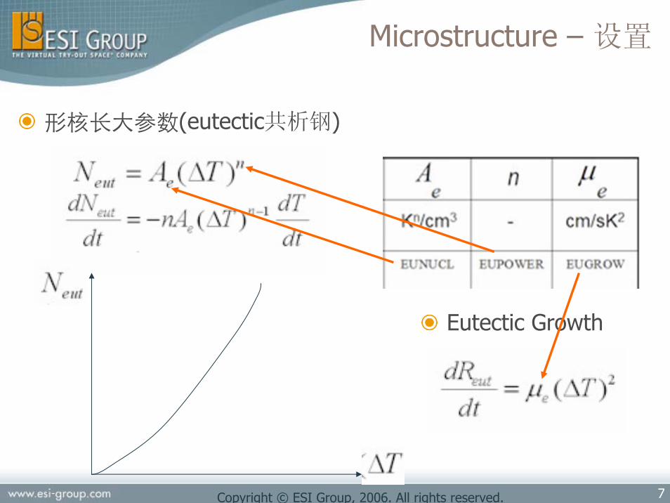
形核长大参数(eutectic共析钢)
Eutectic Growth
Microstructure – 设置

8Copyright © ESI Group, 2006. All rights reserved.
默认值
形核参数 (material properties and may depend upon the metal treatment)
Microstructure – 设置

9Copyright © ESI Group, 2006. All rights reserved.
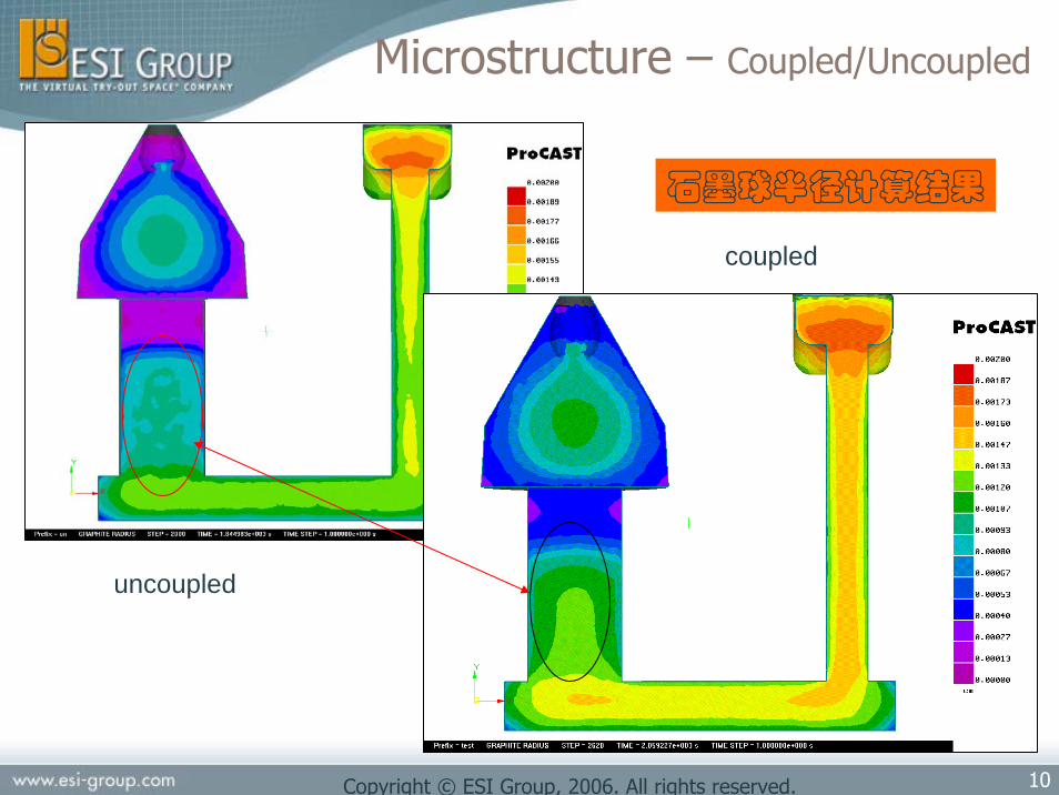
Microstructure – Coupled/Uncoupled
计算慢结果更精确小步长
计算快结果精度一般需要控制时间步长
10Copyright © ESI Group, 2006. All rights reserved.
uncoupled
coupled
石墨球半径计算结果
Microstructure – Coupled/Uncoupled

11Copyright © ESI Group, 2006. All rights reserved.
Microstructure – Coupled/Uncoupled
uncoupled
coupled
铁素体分数

12Copyright © ESI Group, 2006. All rights reserved.
Microstructure – 结果
合金成分不同,
输出结果不同!

13Copyright © ESI Group, 2006. All rights reserved.
Microstructure - Iron and Steel
CE= 4.1 (Hypo-eutectic SGI)
MICRO Output
Automatically computed
钢 铁
亚共析 过共析

14Copyright © ESI Group, 2006. All rights reserved.
Microstructure – Iron and Steel
碳当量(CE) : CE = %C +%Si/3
Steel if CE ≤2
CE > 2, Mg added SGI(has to be added in the chemicalcomposition in the thermo-dynamic database)
Iron if CE > 2
GRAPHITE, MOLDRIG, MGTREAT

15Copyright © ESI Group, 2006. All rights reserved.
Microstructure – Iron and Steel
Example : hypo-eutectic Nodular Cast Iron:
Solidification sequence Primary austeniteEutectic solidification
Slow cooling : stable eutectic (Graphite+Austenite)“Fraction of eutectic”
Fast Cooling : metastable eutectic (Fe3C + Austenite, called ledeburite)
“Fraction of metastable phase”
Cooling and Eutectoïd transformation (720°C)Austenite is transformed into Ferrite (stable) and/or Pearlite(metastable)Slow cooling : Ferrite formation is favorableFast cooling : Pearlite formation is favorable

16Copyright © ESI Group, 2006. All rights reserved.
Microstructure – 铸铁
Default valuesDuctile Iron = SGI, Nodular Cast IronGray Iron
“Porosity related”GRAPHITE, FADING, MGTREAT
“Microstructure related”Dendrites : EQNMAX, EQSTD, EQUNDER
Eutectic : EUNUC, EUPOWER, EUGROW
+ MOLDRIG(Thermal R.P !)

17Copyright © ESI Group, 2006. All rights reserved.
Microstructure – 铸铁
Process-相关的运行参数R.PGRAPHITE :RP/Micro
1, High graphitization 铸件膨胀率大0, No graphitization 铸件无膨胀发生
MOLDRIG :RP/Thermal1, Mold totally rigid 铸型刚性无变形 石墨膨胀可以很好的再次补缩;0, Soft mold 铸件膨胀引起铸型变形 无补缩现象发生
MGTREAT and FADING :RP/MicroSGI is obtained by a Mg inoculation of the melt当FADING激活后, 石墨孕育和膨胀效应会随时间衰退.可以考虑孕育时间 : MGTREAT = time interval between inoculation of melt and start of the calculation孕育时间
Effect on porosity
Effect on porosity
Effect on porosity

18Copyright © ESI Group, 2006. All rights reserved.
Microstructure – Fading Model
“Fading Effect”Mg在合金中孕育处理. 石墨化膨胀效应会随着Mg的含量以及时间衰退 (fading effect).
FADING (between 0 and 1) 用来考虑衰退效应.Inoculation time(孕育时间) is the time between inoculation and solidification = “physical time + MGTREAT” It is not the same as the solidification time
FADING 1 : inoculation effect disappears after 20 minutes of inoculation time
快冷.小铸件 fast cooling, small partsUse MGTREAT to account for treatment time
FADING 0 : no fading, constant inoculation quality, maximum expansion
慢冷,大铸件 slow cooling, large parts

19Copyright © ESI Group, 2006. All rights reserved.
Microstructure – 验证
Trends for microstructure of Cast Iron增大 EUNUC and EUPOWER 值会减少 graphite nodule 和austenite grains晶粒越大,越容易生成珠光体奥氏体半径越小,铁素体数量越多bigger grains to more pearlite
凝固过程中冷却速率的影响快: metastable eutectic亚共析体 (lédéburite莱氏体)中: stable eutectic, small grains, thus more ferrite更多的铁素体慢: stable eutectic, larger grains, thus more perlite更多的珠光体
Cooling rate effect arround eutectoïd transformation共析出转变温度附近(720°C)冷却速率的影响
快: more pearlite更多的珠光体慢: more ferrite更多的铁素体
20Copyright © ESI Group, 2006. All rights reserved.
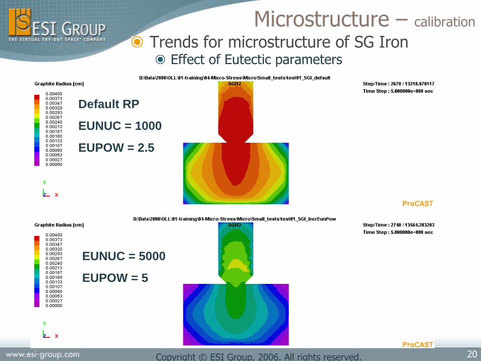
Microstructure – calibration
Trends for microstructure of SG IronEffect of Eutectic parameters
EUNUC = 5000
EUPOW = 5
Default RP
EUNUC = 1000
EUPOW = 2.5

21Copyright © ESI Group, 2006. All rights reserved.
Microstructure – calibration
Trends for microstructure of SG IronEffect of Eutectic parameters
EUNUC = 5000
EUPOW = 5
Default RP
EUNUC = 1000
EUPOW = 2.5

22Copyright © ESI Group, 2006. All rights reserved.
Microstructure – calibration
Trends for microstructure of SG IronEffect of Eutectic parameters
EUNUC = 5000
EUPOW = 5
Default RP
EUNUC = 1000
EUPOW = 2.5

23Copyright © ESI Group, 2006. All rights reserved.
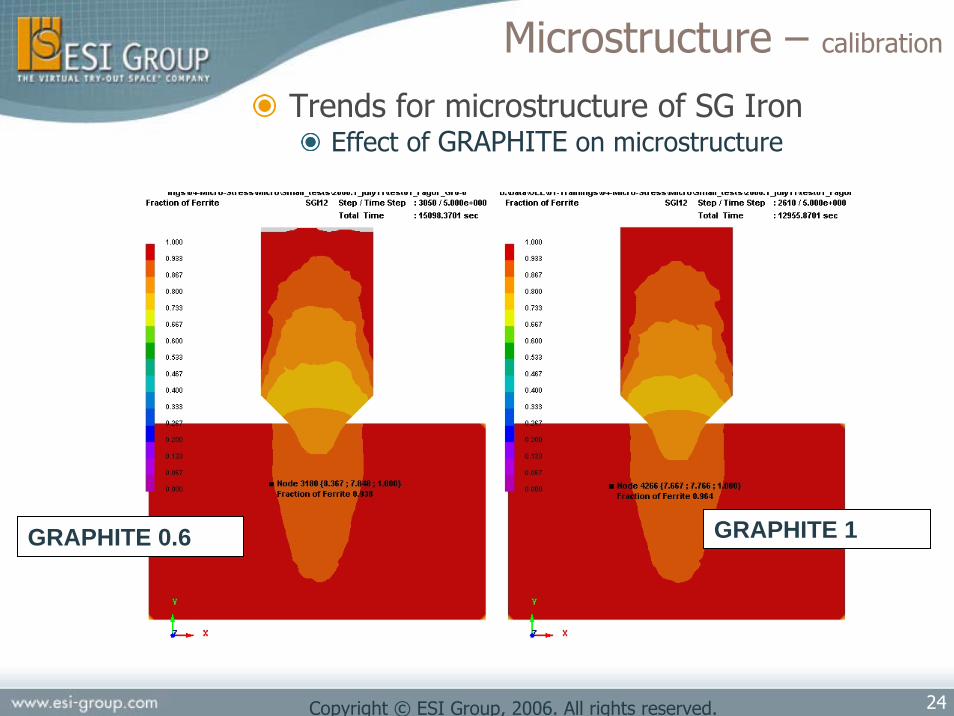
Microstructure – calibration
Trends for microstructure of SG IronEffect of GRAPHITE on microstructure
Default RP
FADING 0
GRAPHITE 0.6 GRAPHITE 1
24Copyright © ESI Group, 2006. All rights reserved.
Microstructure – calibration
Trends for microstructure of SG IronEffect of GRAPHITE on microstructure
GRAPHITE 0.6 GRAPHITE 1

25Copyright © ESI Group, 2006. All rights reserved.
Microstructure – calibration
Trends for microstructure of SG IronEffect of GRAPHITE on microstructure
GRAPHITE 0.6 GRAPHITE 1

26Copyright © ESI Group, 2006. All rights reserved.
Microstructure – calibration
Trends for microstructure of SG IronEffect of FADING on microstrucutre
Default RP
FADING 1Default RP
FADING 0
GRAPHITE and FADING :Small effect on microstructure results (Phase fractions and grain
sizes)Large effect on piping and porosity

27Copyright © ESI Group, 2006. All rights reserved.
Microstructure – calibration
Trends for microstructure of SG IronEffect of FADING on microstructure
Default RP
FADING 1
Default RP
FADING 0

28Copyright © ESI Group, 2006. All rights reserved.
PERNUC=5.e6
PERGROW=8.4e-4
PERNUC=2.e4
PERGROW=2e-5
PERNUC=2e3
PERGROW=8.4e-4
PERNUC=1e6
PERGROW=2e-5
29Copyright © ESI Group, 2006. All rights reserved.
PERNUC=5.e6
PERGROW=8.4e-4
PERNUC=2.e4
PERGROW=2e-5
PERNUC=2e3
PERGROW=8.4e-4
PERNUC=1e6
PERGROW=2e-5

30Copyright © ESI Group, 2006. All rights reserved.
PERNUC=5.e6
PERGROW=8.4e-4
PERNUC=2.e4
PERGROW=2e-5
PERNUC=2e3
PERGROW=8.4e-4
PERNUC=1e6
PERGROW=2e-5

31Copyright © ESI Group, 2006. All rights reserved.
Microstructure – Calibration example
Guidelines for calibration
Step 1: Adjust the Process-related Run Parameters in order to obtain the right expansion and porosity. By order of importance : GRAPHITE, MOLDRIG, FADING and MGTREAT
GRAPHITE : 0.6 to 1 depending on inoculation quality (initial “Expansion Power”)MOLDRIG : 0.5 to 1 depending of mold hardness (sand = 0.7-0.8)FADING
large part with slow cooling rate : FADING 0 FADING = 0.8 to 1 for small parts, high cooling rateMGTREAT : Process Parameter (user should know this…)
Step 2: Adjust the “Eutectic” Run Parameters EUNUCL, EUPOWER and EUGROW (by order of importance) to match the microstructure observation results in terms of Nodule Count and graphite radius.
Suggested range of variation for these parameters were :EUNUC 1000 to 10000EUPOWER 2.5 to 4EUGROW unchanged SGI default value (3.86e-6)

32Copyright © ESI Group, 2006. All rights reserved.
Microstructure – Calibration example
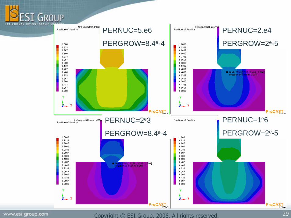
Step 3: Guidelines for calibration : 2008.1 and 2009.0
According to the observed phase proportion (ferrite / pearlite) of the iron matrix, adjust PERNUC and PERGROW that govern the formation of pearlite vs ferrite (eutectoïdtransformation). Note that the value of these two new R.P were previously hard coded in the solver. The “hard coded” values usually lead to too much pearlite. In the present case, the range of variation for these parameters were
PERNUC 1e+4 to 5e+4PERGROW 5e-6 to 2e-5

33Copyright © ESI Group, 2006. All rights reserved.
Microstructure – Calibration example
Industrial case with experimental results Material : Eutectic SGINo porosity observed, very good inoculationMicrostructure observations
Nodule count (unit of surface)Size of graphite noduleRelative amount of phases
Mechanical testsYield StrengthElongationBrinell Hardness

34Copyright © ESI Group, 2006. All rights reserved.
Microstructure – Calibration example
Results7 analysis needed to obtain satisfactory resultsParameters used
GRAPHITE 1MOLDRIG 0.8 FADING 0.8 – MGTREAT 10s
Fading 0 gave NO porosity at all
EUNUCL 8.00000e+003EUPOWER 2.5 (default)EUGROW 3.86000e-006 (default)
PERNUCL 2.000e+004PERGROW 2.000e-005
CONFIDENTIAL

35Copyright © ESI Group, 2006. All rights reserved.
Microstructure – Calibration exampleResults
Graphite NoduleExperimental
2.0e+04 to 2.2e+04 nodules/cm2 15 to 30 microns radius
CONFIDENTIAL

36Copyright © ESI Group, 2006. All rights reserved.
Microstructure – Calibration example
Results : Graphite nodule count from volumetric to surface countThe microstructure module of ProCAST gives the Nodule Count as the number of graphite nodule per unit volume (default unit is cm-3). According to the Wiencek equation, the surface nodule count and the volume nodule count are related by :
Where g is the volume fraction of graphite nodules.The graphite nodules are spheres. If R is their Radius, one has :
So, the Surface Nodule Count is given by :
In Visual 4.5 one can calculate this and display this contour by using the User Defined Results command in the Results menu.
gNN S
V
3
=
VNRg *34 3π=
VS NRN **34 3/1
⎟⎠⎞
⎜⎝⎛= π

37Copyright © ESI Group, 2006. All rights reserved.
Microstructure – Calibration example
ResultsPhase ProportionExperimental : 90% to 100% ferritic
CONFIDENTIAL

38Copyright © ESI Group, 2006. All rights reserved.
Microstructure – Calibration example
Results : Mechanical PropertiesExperimental :
YS=315 - 323 MPaUTS = 448 – 473 MPa
CONFIDENTIAL

39Copyright © ESI Group, 2006. All rights reserved.
Microstructure – Calibration example
Results : Mechanical PropertiesExperimental :
Hardness : 168 – 172 HBElongation : 17 to 20 %
CONFIDENTIAL

40Copyright © ESI Group, 2006. All rights reserved.
Microstructure – Calibration example
Results : Mechanical PropertiesUse of User functions
\ProCAST\2008.0\dat\manuals\Pdf\MechanicalPropertiesManual.pdf
A. Catalina, X. Guo, D.M. Stefanescu Prediction of Room Temperature Microstructure and Mechanical Properties in Iron Castings , in Modelling of Casting, Welding and Advanced Solidification Processes –VIII, B.G Thomas and C. Beckermann Ed. The Minerals Metals and Materials Society, 1998, pp455-462.
Brinell Hardness
( ) NiwtMowtCrwtCuwtMnwtHBand
SiwtHBwith
fHBfHBgHB
pearl
ferr
pearlpearlferrferr
%10%%%%50223
%*3754
100
+++++=
+=
Yield Strength (MPa)
Ultimate Strength (MPa)
Elongation (%)
++=
( )pearlferrY ffg 8.5872.331)1( +−=σ
( )pearlferrUTS ffg 5.9912.482)1( +−=σ
( )pearlferr ffg 61.52.26)1( +−=ε

41Copyright © ESI Group, 2006. All rights reserved.
Microstructure - Conclusion
Cast Iron : Microstructure Module can now predict amount of phases and mechanicakproperties in a reliable manner
New R.P : PERNUC, PERGROW for pearliteformation (eutectoid reaction)Defect prediction : calibration work to be done
By Us ? By User ?Partnership
