cmotion lcs manual
DESCRIPTION
Full C Motion LCS user manualTRANSCRIPT
All content © 2013, cmotion GmbH. All specifications subject to change without notice. http://www.cmotion.eu
V 1.01 | November 8th, 2013
Software Release Package: 2013_02
compactLCS User Guide

All content © 2013, cmotion GmbH. All specifications subject to change without notice. http://www.cmotion.eu
Imprint & Disclaimercmotion GmbH
Kriehubergasse 161050 Wien
Fbnr.: FN220240H – HG WienUID-Nr.: ATU 54026806
http://[email protected]
+43 1 7891096
Technical specifications aresubject to change without notice!
All content © 2013, cmotion GmbH. All specifications subject to change without notice. http://www.cmotion.eu
Table of Contents1. Component Overview .......................................................................................... 3
1.1. compact hand unit ............................................................................................... 3
1.2. compact camin .................................................................................................... 6
1.3. cforce motor ........................................................................................................ 8
2. compact system Accessories .............................................................................. 9
2.1. Battery ................................................................................................................. 9
2.2. Battery Charger ................................................................................................... 9
2.3. cstrap .................................................................................................................. 9
2.4. rod connector .................................................................................................... 10
2.5. Marker Ring ....................................................................................................... 10
3. System Setup .................................................................................................... 11
3.1. Mounting cforce Motors ..................................................................................... 11
3.2. Mounting the camin ........................................................................................... 12
3.3. Connecting the Motors to the camin ................................................................. 12
3.4. Power Supply .................................................................................................... 12
4. System Operation ............................................................................................. 13
4.1. Powering up the System ................................................................................... 13
4.2. hand unit Main Display ...................................................................................... 13
4.3. Entering the Menu ............................................................................................. 13
4.4. hand unit Menu Guide ....................................................................................... 14
4.5. Motor Calibration ............................................................................................... 17
4.6. Setting Controller Speed ................................................................................... 18
4.7. Setting Lens Limits ............................................................................................ 18
4.8. Starting and Stopping the Camera .................................................................... 19
4.9. Turning the System off ...................................................................................... 19
5. Updating System Components ......................................................................... 20

All content © 2013, cmotion GmbH. All specifications subject to change without notice. http://www.cmotion.eu
All content © 2013, cmotion GmbH. All specifications subject to change without notice. http://www.cmotion.eu 1/21
Before UseDear Customer, we would like to take this opportunity to thank you for purchasing the compact Lens & Camera Control System. Please read these Operating Instructions carefully and keep them handy for future reference.
Information for Your Safety ■ Danger of operational error!
■ Danger of injury!
■ Damage to equipment possible!
General Safety Precautions ■ In order to ensure optimal performance, please read the instructions!
■ Do not put your fingers near the motors while motors are moving!
■ Make sure all components (camin, lens motors, etc.) are securely mounted!
■ Remove batteries from components before transport or storage!
■ Repairs should only be made only by authorized service centers!
■ Use only original cmotion replacement parts!
■ In the case of wet weather, routine safety precautions for handling electrical equip-ment in wet weather should be taken!
■ Do not remove any screws that are secured with paint!
■ Do not remove any warranty seals!
Important ■ If you have questions, or you need to order parts, please note the components‘
model and serial number.
■ For support requests, also supply the installed firmware number of all system com-ponents.
■ WARNING: cmotion can only guarantee operation if original cmotion products are used.
All content © 2013, cmotion GmbH. All specifications subject to change without notice. http://www.cmotion.eu 2/21
Using this GuideThis manual is split in three parts. The first introduces you to the compact lens control system, explaining components and concepts. The second takes you step by step through the set-up of the system. The third part guides you through operation and menu options. The table of contents on page 3 provides a reference guide to specific sections of this user guide for quick information.
Note: Notes indicate important information related to the respective sec-tions of this user’s guide.
Warning: Warnings indicate important safety information. Ignoring these could lead to equipment damage or injury.
All cmotion components are written in italics throughout this manual.
CablesWhen a cable is referred to in this user’s manual, it will be referred to as follows (e.g. Le 10p, Fi 3p). Cables are referred to in regards to their connectors. Connectors are manufactured by W. W. Fisher, Lemo or Hirose and are referred to as Fi, Le and Hi respectively. The cable identification begins with the connector that is attached to the cmotion unit or camin followed by the connector which is attached to non-cmotion units or cmotion system component. Each connector takes reference to the number of pins it has e.g. the cable (Le 4p, Le 4p).
Cables may also be referred to by their commonly used names e.g. LBUS (Le 4p, Le 4p) and RS (Fi 3p, Fi 3p) cables, the cable for the CBUS interface and the cable for the RS interface, respectively. The cables, or connectors have either male connectors or female connectors. This is marked as “f” or “m” e.g. Le f10p / Fi m3p.
Necessary Tools4mm Allen keys may be required to complete steps laid out in the manual.
Frequently Used TermsTo Power Cycle: Turn your unit off and on again
All content © 2013, cmotion GmbH. All specifications subject to change without notice. http://www.cmotion.eu 3/21
1. Component OverviewThis section of the User Guide deals with the description of the components and their respective functions, LEDs and buttons.
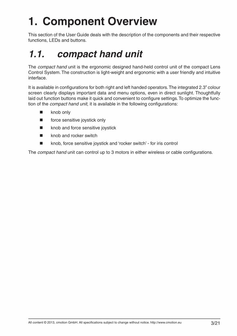
1.1. compact hand unitThe compact hand unit is the ergonomic designed hand-held control unit of the compact Lens Control System. The construction is light-weight and ergonomic with a user friendly and intuitive interface.
It is available in configurations for both right and left handed operators. The integrated 2.3” colour screen clearly displays important data and menu options, even in direct sunlight. Thoughtfully laid out function buttons make it quick and convenient to configure settings. To optimize the func-tion of the compact hand unit, it is available in the following configurations:
■ knob only
■ force sensitive joystick only
■ knob and force sensitive joystick
■ knob and rocker switch
■ knob, force sensitive joystick and ‘rocker switch’ - for iris control
The compact hand unit can control up to 3 motors in either wireless or cable configurations.
All content © 2013, cmotion GmbH. All specifications subject to change without notice. http://www.cmotion.eu 4/21
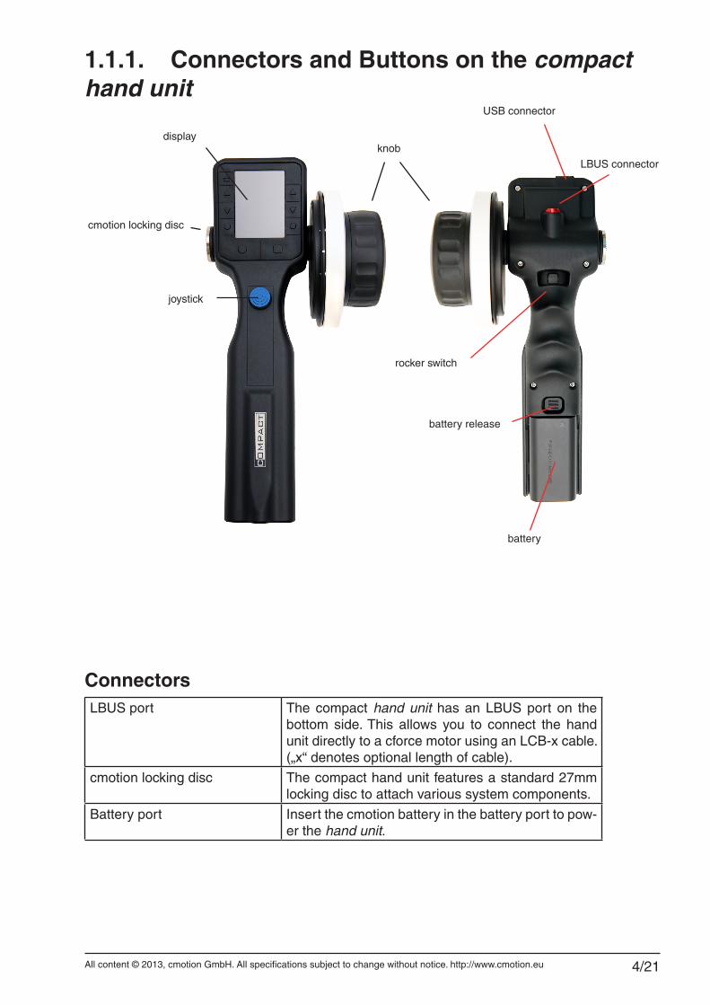
1.1.1. Connectors and Buttons on the compact hand unit
ConnectorsLBUS port The compact hand unit has an LBUS port on the
bottom side. This allows you to connect the hand unit directly to a cforce motor using an LCB-x cable. („x“ denotes optional length of cable).
cmotion locking disc The compact hand unit features a standard 27mm locking disc to attach various system components.
Battery port Insert the cmotion battery in the battery port to pow-er the hand unit.
cmotion locking disc
joystick
knob
rocker switch
battery release
LBUS connector
display
battery
USB connector
All content © 2013, cmotion GmbH. All specifications subject to change without notice. http://www.cmotion.eu 5/21
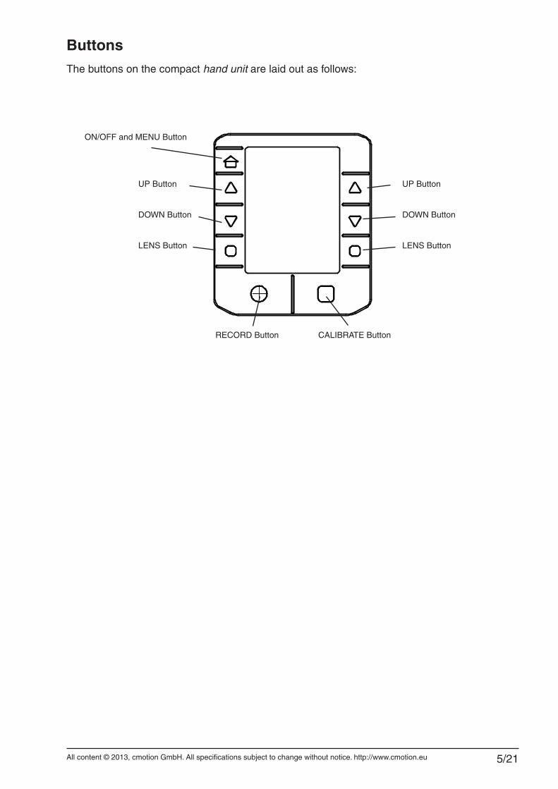
ButtonsThe buttons on the compact hand unit are laid out as follows:
ON/OFF and MENU Button
CALIBRATE ButtonRECORD Button
UP Button
DOWN Button
LENS Button
UP Button
DOWN Button
LENS Button
All content © 2013, cmotion GmbH. All specifications subject to change without notice. http://www.cmotion.eu 6/21
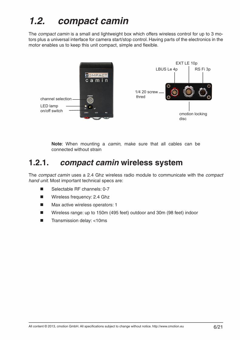
1.2. compact caminThe compact camin is a small and lightweight box which offers wireless control for up to 3 mo-tors plus a universal interface for camera start/stop control. Having parts of the electronics in the motor enables us to keep this unit compact, simple and flexible.
Note: When mounting a camin, make sure that all cables can be connected without strain
1.2.1. compact camin wireless systemThe compact camin uses a 2.4 Ghz wireless radio module to communicate with the compact hand unit. Most important technical specs are:
■ Selectable RF channels: 0-7
■ Wireless frequency: 2.4 Ghz
■ Max active wireless operators: 1
■ Wireless range: up to 150m (495 feet) outdoor and 30m (98 feet) indoor
■ Transmission delay: <10ms
channel selection
LBUS Le 4p
1/4 20 screw thred
RS Fi 3p
cmotion locking disc
EXT LE 10p
on/off switchLED lamp
All content © 2013, cmotion GmbH. All specifications subject to change without notice. http://www.cmotion.eu 7/21
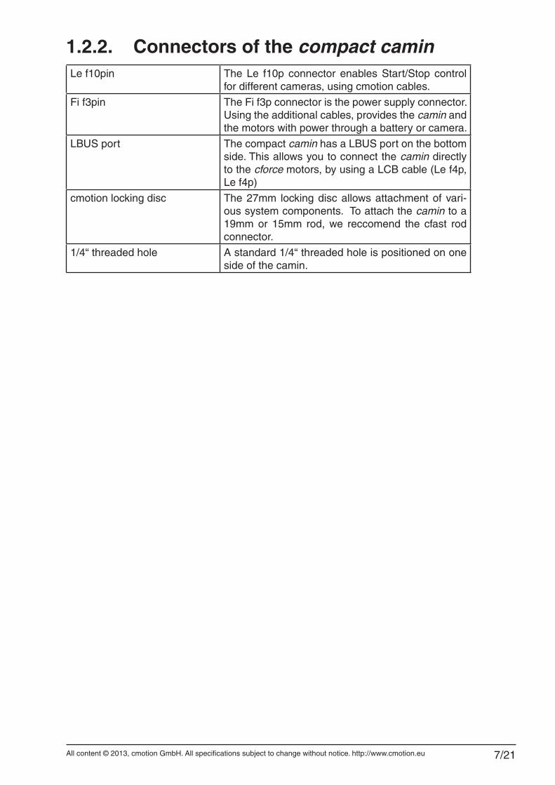
1.2.2. Connectors of the compact caminLe f10pin The Le f10p connector enables Start/Stop control
for different cameras, using cmotion cables.
Fi f3pin The Fi f3p connector is the power supply connector. Using the additional cables, provides the camin and the motors with power through a battery or camera.
LBUS port The compact camin has a LBUS port on the bottom side. This allows you to connect the camin directly to the cforce motors, by using a LCB cable (Le f4p, Le f4p)
cmotion locking disc The 27mm locking disc allows attachment of vari-ous system components. To attach the camin to a 19mm or 15mm rod, we reccomend the cfast rod connector.
1/4“ threaded hole A standard 1/4“ threaded hole is positioned on one side of the camin.
All content © 2013, cmotion GmbH. All specifications subject to change without notice. http://www.cmotion.eu 8/21
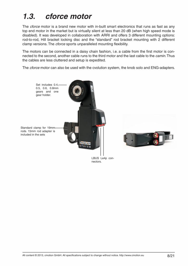
1.3. cforce motorThe cforce motor is a brand new motor with in-built smart electronics that runs as fast as any top end motor in the market but is virtually silent at less than 20 dB (when high speed mode is disabled). It was developed in collaboration with ARRI and offers 3 different mounting options: rod-to-rod, Hill bracket locking disc and the “standard” rod bracket mounting with 2 different clamp versions. The cforce sports unparalleled mounting flexibility.
The motors can be connected in a daisy chain fashion, i.e. a cable from the first motor is con-nected to the second, another cable runs to the third motor and the last cable to the camin. Thus the cables are less cluttered and setup is expedited.
The cforce motor can also be used with the cvolution system, the knob solo and ENG-adapters.
Standard clamp for 19mm rods. 15mm rod adapter is included in the sets
LBUS Le4p con-nectors.
Set includes 0.4, 0.5, 0.6, 0.8mm gears and one gear holder.
All content © 2013, cmotion GmbH. All specifications subject to change without notice. http://www.cmotion.eu 9/21
2. compact system Accessories
2.1. Battery
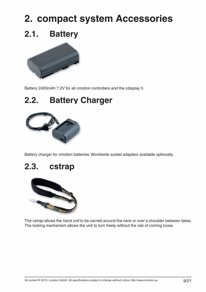
Battery 2400mAh 7.2V for all cmotion controllers and the cdisplay II.
2.2. Battery Charger
Battery charger for cmotion batteries. Worldwide socket adapters available optionally.
2.3. cstrap
The cstrap allows the hand unit to be carried around the neck or over a shoulder between takes. The locking mechanism allows the unit to turn freely without the risk of coming loose.
All content © 2013, cmotion GmbH. All specifications subject to change without notice. http://www.cmotion.eu 10/21
2.4. rod connector
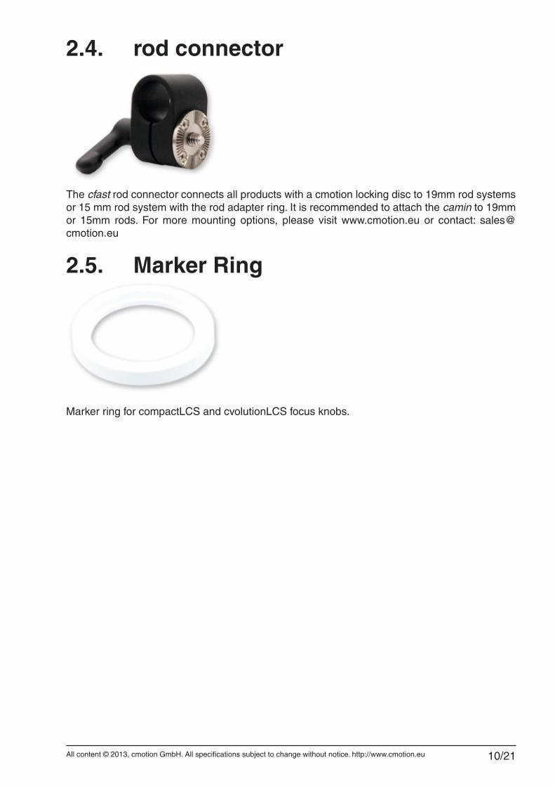
The cfast rod connector connects all products with a cmotion locking disc to 19mm rod systems or 15 mm rod system with the rod adapter ring. It is recommended to attach the camin to 19mm or 15mm rods. For more mounting options, please visit www.cmotion.eu or contact: [email protected]
2.5. Marker Ring
Marker ring for compactLCS and cvolutionLCS focus knobs.
All content © 2013, cmotion GmbH. All specifications subject to change without notice. http://www.cmotion.eu 11/21
3. System SetupThis section will guide you through the compactLCS system setup. Starting with the quick setup of the system then proceeding with the compact hand units to compact camin and cforce motors.
3.1. Mounting cforce MotorsThe cforce motors can be mounted via 3 options:
3.1.1. Rod bracketThe cforce can be mounted to 15 and19 mm diameter rods.
■ Slide the motor onto the rod.
■ Align the motor gear with the gear ring on the lens.
■ Connect the teeth on both rings and hold the motor in place while tightening the clamp. Be careful not to over tighten the screw.
3.1.2. Rod-to-rodTo mount cforce on a secondary rod, use the cmotion Rod-to-Rod adapter.
3.1.3. Hill BracketThe cforce can mounted to a Hill bracket via the cmotion Hill bracket adapter.
Note: When mounting motors make sure the lens scale isn’t set to either limit before engaging the lens gear and calibrating.
All content © 2013, cmotion GmbH. All specifications subject to change without notice. http://www.cmotion.eu 12/21
3.2. Mounting the caminThe camin can be mounted to the camera via a standard 1/4“ threaded hole or a cmotion locking disc. All existing cmotion mounting tools with a locking disc can be used.
3.3. Connecting the Motors to the camin ■ Start connecting the motors from one end of the lens using the supplied LCB ca-
bles. Connect one motor to the next using any of the two cable connectors. Connect the last LCB cable to the camin.
3.4. Power SupplyUse a RRS-1 or RRS-8 cable (Fi 3p, Fi 3p, for Arri style power outlets) to connect the camin to the camera power out connector or a RRS-7 for a D-tap/P-tap battery supply. Alternatively use a cmotion RS power supply or contact cmotion for other power options.
All content © 2013, cmotion GmbH. All specifications subject to change without notice. http://www.cmotion.eu 13/21
4. System Operation
4.1. Powering up the System ■ Make sure the camin is powered via the RS port and a fully charged battery is
inserted into the hand unit.
■ Power up the camin by switching the ON/OFF switch to on.
■ Power up the hand unit by pressing the Menu button.
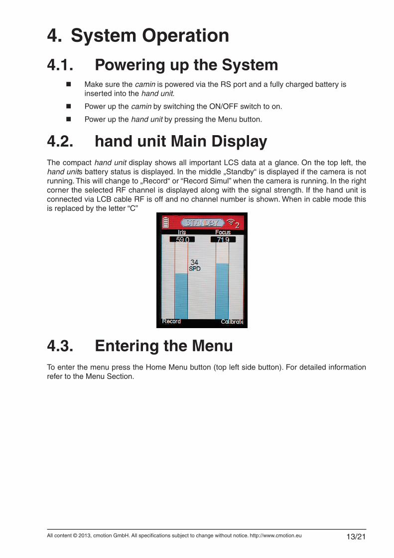
4.2. hand unit Main DisplayThe compact hand unit display shows all important LCS data at a glance. On the top left, the hand units battery status is displayed. In the middle „Standby“ is displayed if the camera is not running. This will change to „Record“ or “Record Simul” when the camera is running. In the right corner the selected RF channel is displayed along with the signal strength. If the hand unit is connected via LCB cable RF is off and no channel number is shown. When in cable mode this is replaced by the letter “C”
4.3. Entering the MenuTo enter the menu press the Home Menu button (top left side button). For detailed information refer to the Menu Section.
All content © 2013, cmotion GmbH. All specifications subject to change without notice. http://www.cmotion.eu 14/21
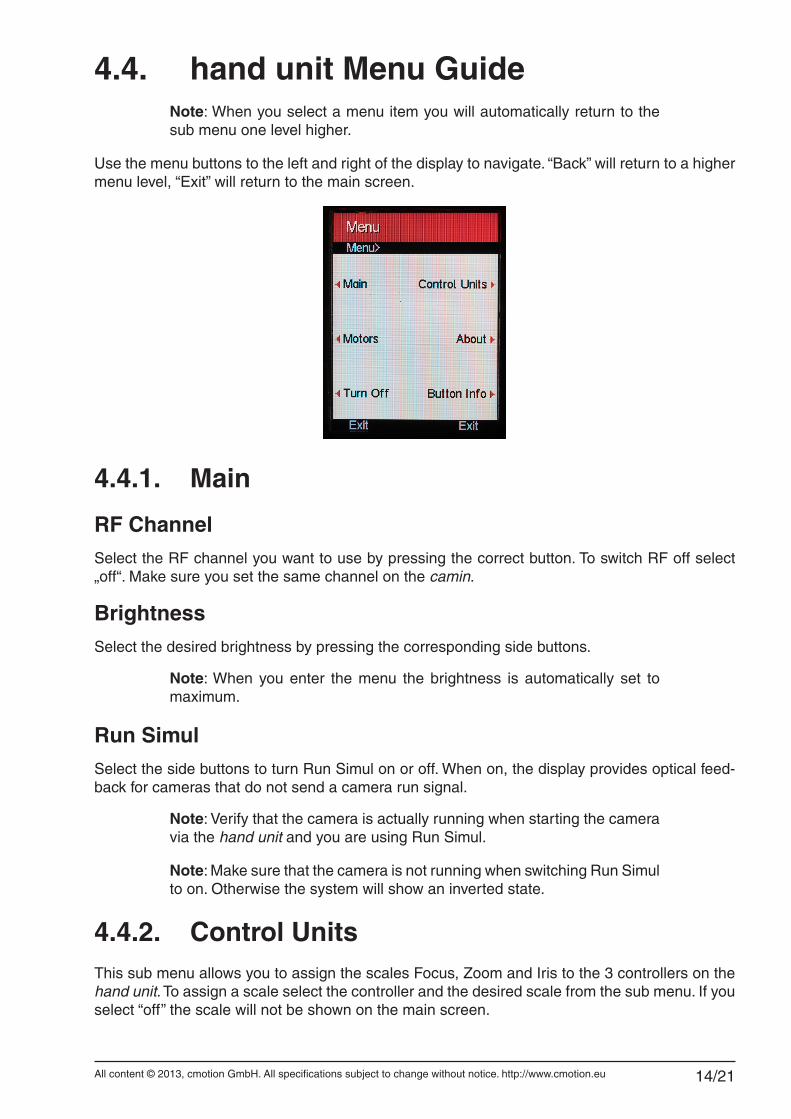
4.4. hand unit Menu GuideNote: When you select a menu item you will automatically return to the sub menu one level higher.
Use the menu buttons to the left and right of the display to navigate. “Back” will return to a higher menu level, “Exit” will return to the main screen.
4.4.1. Main
RF ChannelSelect the RF channel you want to use by pressing the correct button. To switch RF off select „off“. Make sure you set the same channel on the camin.
BrightnessSelect the desired brightness by pressing the corresponding side buttons.
Note: When you enter the menu the brightness is automatically set to maximum.
Run SimulSelect the side buttons to turn Run Simul on or off. When on, the display provides optical feed-back for cameras that do not send a camera run signal.
Note: Verify that the camera is actually running when starting the camera via the hand unit and you are using Run Simul.
Note: Make sure that the camera is not running when switching Run Simul to on. Otherwise the system will show an inverted state.
4.4.2. Control UnitsThis sub menu allows you to assign the scales Focus, Zoom and Iris to the 3 controllers on the hand unit. To assign a scale select the controller and the desired scale from the sub menu. If you select “off” the scale will not be shown on the main screen.
All content © 2013, cmotion GmbH. All specifications subject to change without notice. http://www.cmotion.eu 15/21
4.4.3. MotorsThe motors menu will allow setting motor scale, direction, torque and ramp length. Motor set-tings will be stored in the motor.
Note: The menu shows the motor name (only cforce motors can be used at the time of writing) and the serial number of the motor in blue.
Select the motor you want to adjust by pressing the corresponding button.
ScaleSelect the desired scale from the menu by pressing the corresponding side button. You can as-sign a motor to Focus, Iris and Zoom.
DirectionTo change motor direction select the Direction side button. Select left or right by pressing the appropriate side button.
TorqueNote: To prevent the lens from being damaged, adjust the torque to the lens barrels friction (high friction = more torque and vice versa).
To adjust motor torque select the correct torque setting by pressing the corresponding side but-ton. Available settings are “min”, “weak”, “strong” and “max”.
RampTo adjust motor ramp select “min”, “short”, “long” or “max” from the menu by pressing the corre-sponding side button. The motor will start and stop slowly when set to “max”, and more instant when set to “min”.
High Speed ModeWhen the speed limit is set to ‘ON’ the motor can turn a maximum of 2 revolutions per second (depending on power supply and lens resistance). When the speed limit is set to ‘OFF’ the motor is capable of 3 revolutions per second when supplied with a minimum of 18V. When High Speed Mode is turned off, this is indicated by “Speed Limit” on the display.
Note: The motor can only run at less than 20dB when speed limit is turned on.
All content © 2013, cmotion GmbH. All specifications subject to change without notice. http://www.cmotion.eu 16/21
4.4.4. AboutThe about menu will show all units present in the system. It lists the units‘ names, serial numbers and software versions. This information is very important when contacting support.
4.4.5. Turn OffPressing this button will turn off the system. Alternatively press and hold the “Menu” button for 4 seconds.
4.4.6. Button InfoThis button will exit the menu and display information on button functions on the main screen.
4.4.7. ExitPress one of the two bottom buttons to exit the menu.
All content © 2013, cmotion GmbH. All specifications subject to change without notice. http://www.cmotion.eu 17/21
4.5. Motor Calibration
4.5.1. Automatic Motor Calibration ■ To calibrate motors press the side button marked “Calibrate”.
■ On the calibration screen select a single motor or “All motors”.
■ Select “Automatic’” to start calibration.
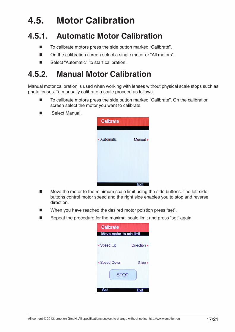
4.5.2. Manual Motor CalibrationManual motor calibration is used when working with lenses without physical scale stops such as photo lenses. To manually calibrate a scale proceed as follows:
■ To calibrate motors press the side button marked “Calibrate”. On the calibration screen select the motor you want to calibrate.
■ Select Manual.
■ Move the motor to the minimum scale limit using the side buttons. The left side buttons control motor speed and the right side enables you to stop and reverse direction.
■ When you have reached the desired motor poistion press “set”.
■ Repeat the procedure for the maximal scale limit and press “set” again.
All content © 2013, cmotion GmbH. All specifications subject to change without notice. http://www.cmotion.eu 18/21
4.6. Setting Controller SpeedThe speed for the joystick and rocker switch can be set on a range from 1 to 99 to suit different shooting needs. To set the joystick/rocker switch speed:
■ To increase the controller speed press the corresponding UP side button. Keep the button pressed for large speed changes.
■ To decrease the controller speed press the corresponding DOWN side button. Keep the button pressed for large speed changes.
Note: The left side buttons are controlling the joystick. The right side con-trols the rocker switch. When only the knob and one other controller is enabled the right side buttons are disabled.
Note: If the motor being controlled by the pressure sensitive button or rocker is not moving, check the corresponding speed setting.
4.7. Setting Lens LimitsTo set a Lens Limit for a controller:
■ Move the controller to the first lens limit.
■ Press and hold the joystick or knob lens side button.
■ Move the motor to the second limit while keeping the side button pressed.
■ Release to side button. The Lens Limit will be indicated by two black bars over the scale graph on the display.
Note: To set a limit for the rocker switch you need to press the rocker switch while moving to the second limit.
To remove a Lens Limit:
■ Press the Lens side button.
■ The Limit is now reset and the black bars are removed from the scale on the dis-play.
All content © 2013, cmotion GmbH. All specifications subject to change without notice. http://www.cmotion.eu 19/21
4.8. Starting and Stopping the CameraYou can start a connected camera with the side button marked „Record“. The camera control cables are connected to the camin’s EXT Le10p connector. For a list of compatible cameras and cables, please refer to the cmotion webshop at www.cmotion.eu.
4.9. Turning the System off ■ Switch off the hand unit by pressing the Menu button for 4 seconds or by entering
the menu by pressing the menu button and pressing the „Turn off“ side button.
■ Switch off the camin by setting the On/Off switch to off.
All content © 2013, cmotion GmbH. All specifications subject to change without notice. http://www.cmotion.eu 20/21
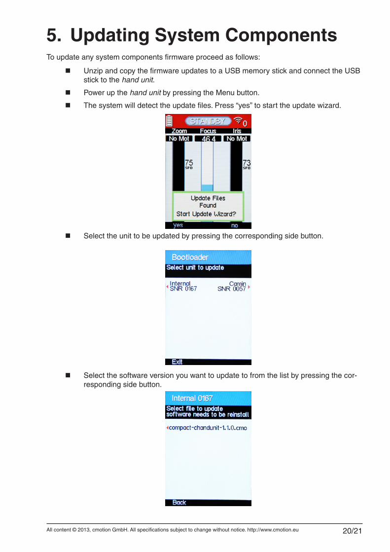
5. Updating System ComponentsTo update any system components firmware proceed as follows:
■ Unzip and copy the firmware updates to a USB memory stick and connect the USB stick to the hand unit.
■ Power up the hand unit by pressing the Menu button.
■ The system will detect the update files. Press “yes” to start the update wizard.
■ Select the unit to be updated by pressing the corresponding side button.
■ Select the software version you want to update to from the list by pressing the cor-responding side button.
All content © 2013, cmotion GmbH. All specifications subject to change without notice. http://www.cmotion.eu 21/21
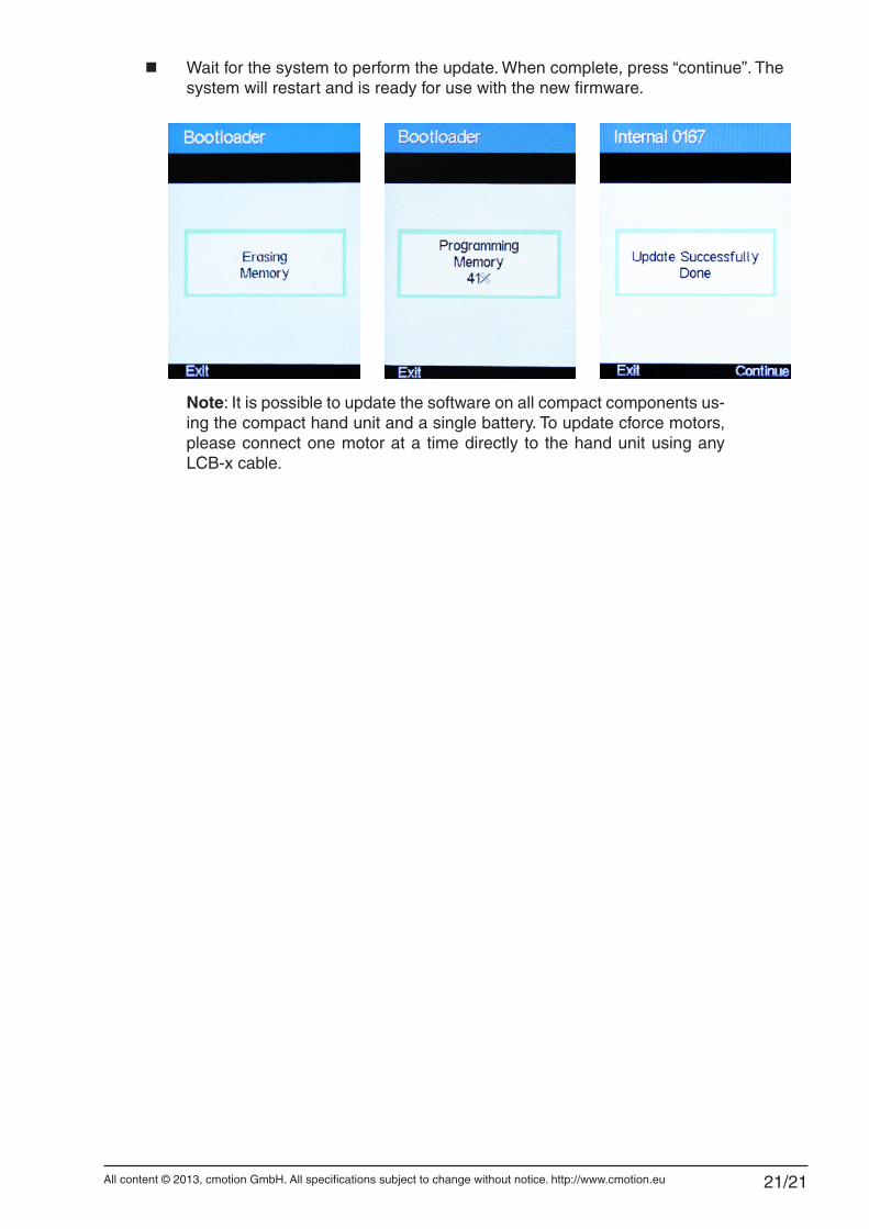
■ Wait for the system to perform the update. When complete, press “continue”. The system will restart and is ready for use with the new firmware.
Note: It is possible to update the software on all compact components us-ing the compact hand unit and a single battery. To update cforce motors, please connect one motor at a time directly to the hand unit using any LCB-x cable.