cn h - defense technical information center · tests indicated that the device increases the...
TRANSCRIPT

"."J- -«■«■»}•." ■ Tl
CN CN
ON
Q <
I
h < O J
o z o ►—I
to J b a. O öS CL,
W I
o EC.
a,
D a, J w w
o
w I—I
Q D h
2 w 3> wo
CO
<U
X) o
—. 3
>> bO O
•—i o c
X! o 4)
O c/j VH
)H " £ JC *-> 0) W «Z c —> »-< M •t
X) 0
OS si HH' C/> £
o\ vO ON «—<
>H
Q) X)
e 4) o <u Q
E

'"•■'' '"- • «-TP— HHHß*PMlM*li'.11 ,!■ ill l ma»"»»
R-lMS
1
1
REPORT SIT-OL-69-1%19 DDC
npaEanäa «« IS 1970
©EU ins1
PRELIMINARY STUDIES OF A WHEEL PUMP
FOR THE PROPULSION OF FLOATING VEHICLES
by
!. R. Ehrlich
and
C- J. Nuttall
December 1969 ClEARINGHOUSi
,r Federal Scent.de & Tochn.ca liotmaiion Spnng'ieid V.i .-'-'i
tetr public md*»» and «ak; Ms
5
H

BLANK PAGES IN THIS DOCUMENT WERE NOT FILMED

r a >
DAVIDSON LABORATORY
SIT-DL-69-1M9
December 1969
PRELIMINARY STUDIES OF A WHEEL PUMP
FOR THE PROPULSION OF FLOATING VEHICLES
by
I. R. Ehrlich
and
C. J. Nuttall
Prepared for the I'.S. Army Tank-Automotive Command
under Contract DAAE07-68-C-2608
(DL Projects 3^7,8Al6,7)
xl ♦ 19 pages 36 figures
!. Robert Ehrlich, Manager Transportation Research Group

mmummmmmm 1 ■ I i —mi■^^f»^»*w
R-1419
ABSTRACT
A novel propulsion device for an «mphlbous wheeled vehicle
Is described. This device,which Is an Integral part of the vehicle
wheels, pumps water between the tire rim and the brake drum Inboard
Into a stationary collector which turns the water rearward, thereby
generating forward thrust.
Results of preliminary tests conducted on a stationary pumping
system and when mounted on a HI5I i~ton truck are presented.
Tests Indicated that the device Increases the maximum bollard
pull approximately 100% ard the maximum speed approximately k0% over
propulsion with tires alonr.. It also materially Improves the con-
trollability of the vehicle.
KEYWORDS
Amphibians
Swimmers
Floaters
Propulsion
ill
J

R-1M9
TABLE OF CONTENTS
Page
INTRODUCTION ......... I
ANALYSIS . .......... 2
FABRICATION 6
TESTS 7
Pump Performance Tests ........... 7
Propulsion Performance Tests .............. $
Bollard Pull Tests 9
Free Running Tests ..... !3
Summary of Results 15
SUMMARY OF RESULTS 15
CONCLUSIONS 16
RECOMMENDATIONS 17
ACKNOWLEDGEMENTS S 18
REFERENCES 19
FIGURES 1-36

"*OTBniK^amimN4"' '■''"! "''"'
R-I4I9
LIST OF TABLES I
TABLE I RESULTS OF PUMP TESTS IN RECIRCULATED TANK TEST STAND
TABLE II TESTS ON Ml5i WITH SUBMERGED WHEELS \
TABLE III BOLLARD PULL - PUUNDS/HORStPOWER
TABLE IV SPEED TESTS - SELF-PROPELLED
VI

R-1419
LIST OF FIGURES
Figure
1 Early Wheel Pump Concept Sketch
2 Simplified Pump System Schematic
3 Relation Between Specific Speed, 6, Specific Diameter, a, for Various Pressure Coefficients, \|t, and Capacity Coefficients, cp
4 Eight- and Sixteen-Bladed Pumps Employed During the Program
5 Ar Elght-Bladed Pump Mounted on the Ml51 £-Ton Test Vehicle
6 Water Collector Mounted on Vehicle (Side View)
7 Water Collector Mounted on Front Suspension (Front View)
8 Water Collector Mounted on Front Suspension (Rear View)
9 Recirculating Tank Test Stand Used to Measure Pump Output and Efficiency
f 10 Schematic Drawing of the Recirculating Test Stand
11 Test Vehicle Mounted in Support Raft
12 Load-Cell Connection between Test Vehicle and Support Raft
13 Vehicle During Operation, Showing Support Cables
14 Schematic of Test Vehicle/Support Raft Arrangement When Towed by Boat
15 Summary of Bollard Pull Tests - Tires Only Without Wheel Pumps from Figures 16-19
16 Bollard Pull Tests - Four Wheel Drive, No Wheel Pumps, 7-50-16 NDCC Tires, No Skirts
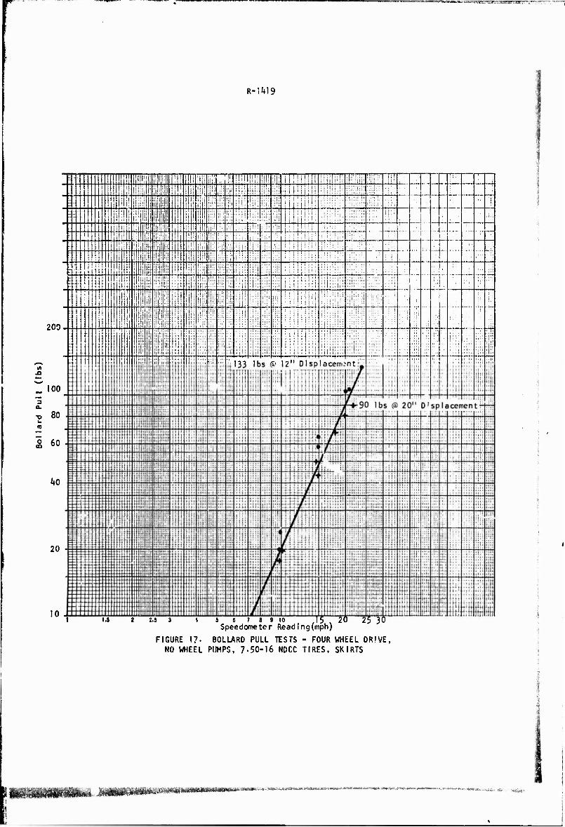
17 Bollard Pull Tests - Four Wheel Drive, No Wheel Pumps, 7-50-16 NDCC Tires, Skirts
18 Bollard Pull Tests - Rear Wheels Only, No Wheel Pumps, 7-50-16 NDCC Tires No Skirts
Ix

R-1^19
List of Figures (Cont'd)
Figure
18 Bollard Pull Tests - Rear Wheels Only, No Wheel Pumps, 7-50-16 NDCC Tires, No Skirts
19 Bollard Pull Tests - Rear Wheels Only, No Wheel Pumps, 7-50-16 NDCC Tires, Skirts
20 Summary of Bollard Pull Tests - Tires with Wheel Pumps, from Figures 21-24
21 Bollard Pull Tests - Four Hheel Drive, Wheel Pumps, 7.50-16 NDCC Tires, No Skirts
22 Bollard Pull Tests - Rear Wheels Only, Wheel Pumps, 7.50-16 Tires, No Skirts
23 Bollard Pull Tests - Four Wheel f*rlve, Wheel Pumps, 7.50-16 Tires, Skirts
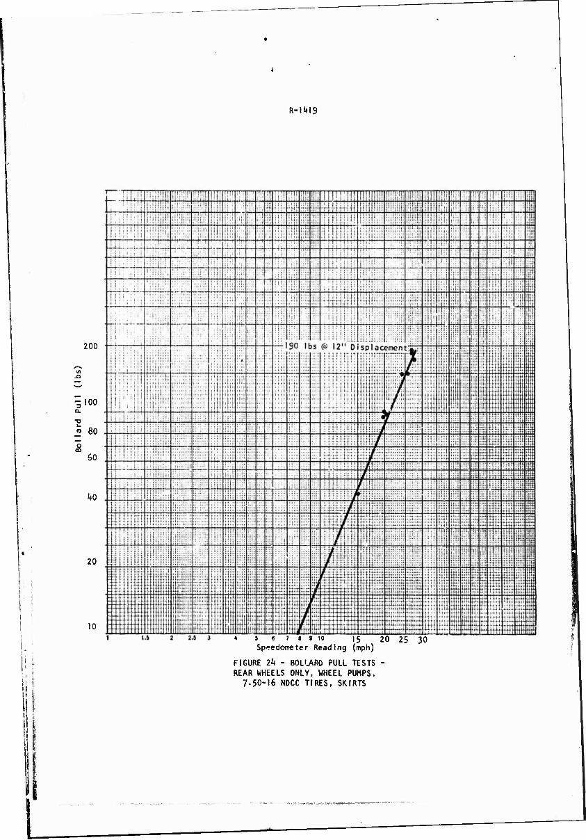
2k Bollard Pull Tests - Rear Wheels Only, Wheel Pumps, 7.50-16 NDCC Tires, Skirts
25 Changes in Bollard Pull Performance Using the Wheei Pumps
26 Summary of Bollard Pull Tests - Smooth (Treadless) 6.50-I6 Tires with Wheel Pumps from Figures 27-30
27 Bollard Pull Tests - Rear Wheels Only, 16-Bladed Wheel Pumps, 6.50-16 Smooth Tires, No Skirts
28 Bollard Pull Tests - Rear Wheels Only, 8-Bladed Wheel Pumps, 6-50-16 Smooth Tires, No Skirts
29 Bollard Pull Tests - All Wheel Drive, Wheel Pumps, No Skirts, 16-Bladed Pump In Rear
30 Bollard Pull Tests - AH Wheel «ve, Wheel Pumps, 6.50-16 Smooth Tires, No Skirts, 8-Bladed Pump in Rear
31 Bollard Pull Tests - Effects of Tire Tread on Thrust
32 Collector with 50% Exit Restriction Nozzle
33 Summary of Bollard Pull Tests - Effect of 50% Reduction In Exit Area, From Figures 20, Ik and 36
}k Bollard Pull Tests - Four Wheel Drive, Wheel Pumps with 50% Exit Nozzle, 7-50-16 NDCC Tires, Skirts
^m&^'M^M^imsmammmimM va*™*™»» ^'tmmtttBjmausamrsmmKtH/mm

R-1419
Figure
35
36
37
38
39
List of Figures (Cont'd)
Bollard Pull Tests - Front Wheel Drive Only, Wheel Pumps with 50% Exit N.zzle, 7-50-16 NOCC Tires, Skirts
Bollard Pull Tests - Rear Wheel Drive Only, Wheel Pumps with 50% Exit Nozzle, 7-50-16 NDCC Tires, Skirts
Summary of Bollard Pull Tests - Effect of Pump Location, from Figures 3V36
Free Running Tests
Concept Sketch of Utilizing Tire Tread Pattern to Achieve Improved Vehicle Thrust
xl

R-|l»19
NOMENCLATURE
A Area i
A„ Effective Cross-Sectional Areas of the Pump j
A. Vehicle Submerged Frontal Area S CJJ Drag Coefficient
CT Pump Thrust Coefficient 'P
D impel>er Diameter
E Energy
H Pressure Head Across Pump
HP Output Horsepower
Q. Flow Volume
T Thrust
U Vehicle Velocity
V Velocity
g Gravitational Constant
n Impeller Rotational Speed <rps)
p Pressure
u The Increased Flow Velocity Imparted by the Pump
v Mean Flow Velocity Across Pump
6 Specific Diameter
T\ Efficiency
Y Specific Weight
X U/nnD ■ Advance Coefficient
cp Capacity Coefficient
t Pressure Coefficient
p Density
a Specific Speed
xhi

WWWWWWW—W
I
I
R-1419
INTRODUCTION
It has long been known to the designers of amphibious and floating
vehicles that the addition of a screw propeller or waterjet is needed to I achieve reasonable water speeds, as on the highly successful World War II
DUKW, the amphibious Volkswagon, the LARC V and XV, and, more recently,
the LVTf'-X!2. Unfortunately, waterjets and propellers add additional
co"- ols, machinery, and weight to a vehicle and propellers, and, if they are
to ue properly located for good hydrodynamlr performance, often are severe
impediments to cross-country operations unless complex propeller retraction i
gear Is provided*
It is no surprise, therefore, that most Army "swimmers," which are
designed primarily for cross-country operations, do not have any auxiliary
propulsion device but rely wholly on what thrust they can obtain by simply
spinning their wheels in the water. If the wheel is partially submerged,
as in the GOER vehicles, the tire acts as a paddle wheel and moderate
speeds (2-3 mph) may be obtained- If, on the other hand, the wheels are
totally submerged, as In the XM656 the propulsive efficiency Is still
further decreased and only minimal (l£ to 2 mph) speeds are attainable*
Somewhat improved propulsion can be obtained by the use of suitable 2
shrouding around the tires, but those shrouding arrangements that sub-
stantially improve propulsion are totally unacceptable for cross-country
operations.
There is, therefore, a need for a compatible propulsion system
which will provide adequate thrust to yield reasonable water speeds, yet
not Interfere with the basic off-road mission of the vehicle. Such a
concept, herein designated a "wheel pump," was conceived some time ago
by the authors (Figure 1). Basically, the wheel-pump concept envisions
some simple wheel alterations to enable the turning wheel to pump water
axially toward the center of the vehicle into a simple, static device
designed to redirect the flow rearward, thereby obtaining forward thrust.
F;-!M9
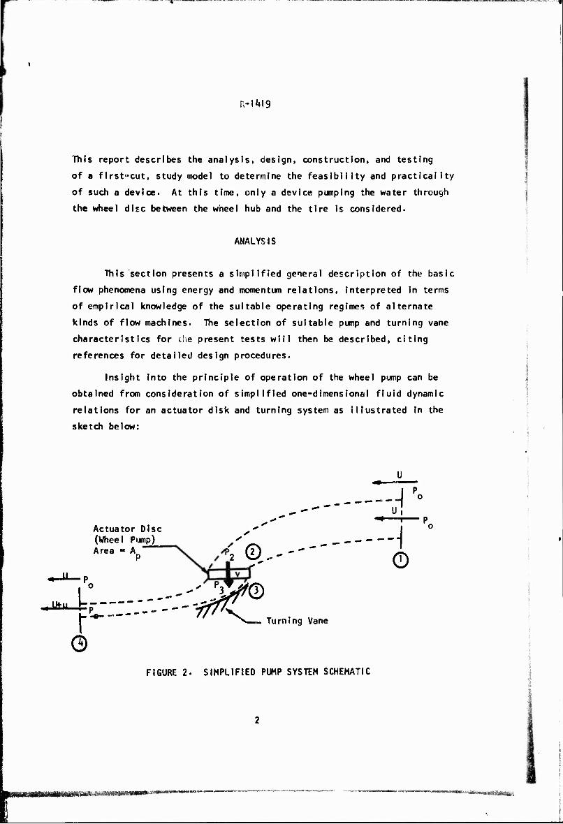
This report describes the analysis, design, construction, and testing
of a first-cut, study model to determine the feasibility and practicality
of such a device. At this time, only a device pumping the water through
the wheel disc between the wheel hub and the tire Is considered.
ANALYSIS
This section presents a simplified general description of the basic
flow phenomena using energy and momentum relations, interpreted in terms
of empirical knowledge of the suitable operating regimes of alternate
kinds of flow machines. The selection of suitable pump and turning vane
characteristics for the present tests will then be described, citing
references for detailed design procedures.
Insight into the principle of operation of the wheel pump can be
obtained from consideration of simplified one-dimensional fluid dynamic
relations for an actuator disk and turning system as illustrated in the
sketch below:
JitJt.
Actuator Disc (Wheel Pump) Area ■ A
P
©
\ ©---
-"' J^© Turning Vane
A -»-—t— p
-i ©
FIGURE 2. SIMPLIFIED PUMP SYSTEM SCHEMATIC
BM-*wn*<^«£&^

R-1419
Several assumptions will be made for the sake of convenience:
1. No losses occur In the flow within the stream tube enclosed
by the dotted lines, which retains Its Identity;
2. The flow through the pump is assumed to be entirely normal
to the actuator disk so that the flow rate Q ■ A v; fand P
3- The turning vane produces a complete turning of the pump
outflow Into the direction of motion.
Admittedly, these assumptions may be far from the truth, especla ly for
the present case of propelling amphibious vehicles, but the qualitative
results of the analysis will be Instructive-
Let the water enter the imaginary stream tube at velicity U, the
velocity of the vehicle, and exit at velocity U + u due to the action
of the pump. The thrust of '.se pump is generated by the momentum imparted
to the exit flow:
■ PQu ■ p A vu (I)
The energy lost in the slipstream is residual kinetic energy left
In the water:
Elost"2 pQu 2 pApVU (2)
The efficiency of the system is the useful work (the thrust x velocity)
divided by the sum of the useful work and the lost energy, or
T) TU L
Ideal TU + E 2 + u/U ' (3)
Applying Bernoulli's equation to the stream tube between Stations I
and 2 and between 3 and k separately, since energy is added to the stream
at the pump, it is possible to derive the pressure- difference across the
actuator disk:

R-i4J9
P3-P2-V[<-s>2*2ij] eo
Solving for u/U In terms of the pump thrust coefficient:
(p - p2)A£
T 1 2 '
u i
I + (1 + c, ) , 'p
(5)
and the ideal efficiency may be expressed as
2 'ideal TT7T?
(6)
where, although the thrust on the actuator disk does not contribute
directly to propelling the system, it does appear to control the "best"
achievable system efficiency. The system thrust coefficient, non-
dimensional I zed on the basis of the actuator disk area and the uniform
steam speed, may be obtained from Eqs. (1) and (5) as
(7) 2'V
In pump design practice, two coefficients are used which specify
the headrlse and capacity of the pump in terms of the impeller's tip speed
TTnO. These are the pressure coefficient, in
1 2
p±lh j « cT X p(nnO) P
(8)
and the capacity coefficient, cp:
9 " Ap(TTnD) A U v
\ , (9)

mm '-»■»■ —■—"w
s 5 R-1M9
where \ 13 the advance coefficient:
U/TTnO . (10)
The thrust-producing system is to be designed to suit a particular
drag coefficient for the vehicle In water, Cß, based on the vehicle's
significant area A, seeking the most efficient solution possible. Eq. (7)
may therefore be rewritten in terms of this drag coefficient and the pump
parameters:
f [-1 + (1 +*A2) ] , (n:
where £A is the total flow area of all pump impellers In operation. P
Note that from Eq. (6) the thrust coefficient of the pump, CT , should
be as small as possible for good efficiency. Therefore from Eq. (8), 2
the value of tA should also be small. 3
Figure 3, takjn from a paper by vanHanen and Oosterveld , shows
the relation between specific speed, a, and specific diameter, 6* Best
efficiency for various pumping machines of different geometric design
lies within the cross-hatched area, where:
c " n [ *? 2?s A J • L (2gH) J
- 2Q* J
and (12)
(13)
On this chart are plotted curves of constant pressure coefficient, t,
and constant capacity coefficient cp.
For the Ml51 we may use the following vehicle characteristics:
—hsmm—ww

Lnrsi.7wi7Ts-*:*":i"«."x ; /■
R-l*tl9
CD - 0.8
A «11.28 ft2
s
A * .76? per wheel P
From this data and Eq. (11) we can now plot on Fig- 3 curves for several
values of \(\ « 0.2 corresponds to approximately 28 mph wheel speed and
3 mph water speed for the wheel pumps in the Ml51)- If we desire to
reduce the frictional losses experienced at the tire tread we should
reduce the pump speed, thereby increasing \. Therefore a radial (centri-
fugal) pump appears to hold the best promise.
Since the above analysis is quite simplified and neglects such
important factors as losses due to viscous eddying in the pumps, collectors
and turning vanes, it was decided to design and test two types of pumps,
both of the mixed flow type: one having eight blades and the other having
sixteen blsdes. Another pump, of the axial flow type WJS designed but
was not tested. Detailed design procedures are contained in standard
pump textf>ooks, such as that by Betz. The flow collector and turning
vanes were laid out to suit mechanical restrictions imposed by suspension
and underbody arrangements.
FABRICATION
Employing the equations developed in the preceding section, wheel-
pumps and collectors were designed and fabricated to fit the configuration
of the Ml51 bxk jeep. In order to avoid any structural modifications to
the M151 suspension, wheel centerlines were moved outboard by k inches
on each side. Figure k shows the two variations in impeller design (8 and
16 blades) tested. Figure 5 shows the 8-bladed impeller mounted on the
rear wheel of the Ml51 * Figures 6, 7 and 8 show the collectors mounted
on the vehicle. It can be easily seen in Figure 7 that the collector
imposes no steering restraints to the vehicle.
;,. Bestow*!* ■• m***—*-

=?-""
R-1419
The wfiee I pump and collectors were both made of sheet steel. Upon
completion, the combination impeller wheel and brake drum plus the collector
weighed 46 pounds per wheel or 23 pounds more per wheel station than the
standard wheel and brake drum it replaced- For actual service It would
not be necessary to make the collector of steel. Some rubber-fabric
material that would collapse when not In use, but inflate under water
pressures during pumping, should be equally serviceable.
TESTS
The 8-blade and 16-blade wheel pumps were first mounted on a test
stand (without tire) to obtain an estimate of their performance as pumps
and then on the vehicle to evaluate their potential as a vehicle propulsor.
Pump Performance Tests
Performance of the wheel pump was evaluated prior to installation
on the vehicle, using a simple recirculating tank test stand (Fig. 9). A
schematic of this setup is shown in Fig- 10. Table I summarizes tie
results of these tests. Pump speed was measured by a tachometer. Input
torque was measured by a damped spring-scale connected to the pivot-
mounted engine. Flow velocity and head across the pump were measured by
manometers and output horsepower was computed from
HPQ -= Y • v • H • Av (1*0
where
t Y
9 « specific weight of wacer (lb/ft)
v ■ average water flow (ft/sec) at the measuring section
H ■ difference in head across pump (ft)
A ■ cross-sectional area where V was measured (sq ft)
...

R-1419
TABLE I
RESULTS OF PUMP TESTS IN RECIRCULATED TANK TEST STAND
Test Pump Input Velocity Input Output Efficiency Number Throttle Damper Nc. Speed
(RPM)
212.6
Power (HP)
1-71
(FPS)
2.21
Head (FT)
2.6
Power (HP)
0.08
Blades PosJ tion Pos i tion
2 0.048 8 Part Open 3 248.8 2.67 2.62 3-7 0.13 0.052 8 hid Open 4 255-6 2.92 2.52 4.2 0.15 0.052 8 Full Open 7 214.9 1.80 2-27 3-3 0.10 0.060 8 Part Open 8 248.8 2-59 2.63 4.6 0.17 0.066 8 Mid Open 9 255-6 2.83 2.59 4.7 0.17 0.061 8 Full Open
12 217-2 1-75 1.91 5-1 0.13 0.079 8 Part Part 13 251.1 2-70 2.36 7.2 0.24 0.090 8 Mid Part 14 257-9 2.86 2.44 8.! 0.28 0.098 8 Full Part 16 217-2 1.75 2.03 5-5 0.15 0.090 8 Part Part 17 251.1 2.70 2.45 7.5 0.26 0.096 8 Mid Part 18 257-9 2.86 2.21 8.0 0.25 0.088 8 Full Part 21 210.4 1.48 0.65 17-3 0.16 0.108 8 Part Closed , 22 253.3 2.47 1.00 24.6 0.35 0.142 8 Mid Closed 24 271.5 3.10 0.72 26-3 0.27 0.087 8 Full Closed 26 217.2 i.ec 0.79 18.5 0.20 0.129 8 Part Closed 27 251.1 2.44 0.91 23-3 0.30 0.123 8 Mid Closed 28 266.9 2.96 0.55 25-3 0.20 0.068 8 Full Closed i
31 217-2 I.82 1.84 1.1 0.02 0.016 16 Part Open ;
32 248.8 2.76 2.00 1.2 0.03 0.012 16 Mid Open *
33 253-3 2-89 2.02 1.6 0.04 0.016 16 Full Open i
35 217-2 1-89 1.69 1.1 0.02 0.014 16 Part Open ■
36 248.8 2.84 2.02 1.2 0.03 0.012 16 Mid Open .
37 248.8 2.84 2.22 1.6 0.05 0.018 16 Full Open \ 39 217-2 1.89 2.07 2-5 0.07 0.038 16 Part Part
'■
40 239-8 2-57 2.44 3-1 0.10 0.042 16 Mid Part ■
41 248.8 2-76 2-34 3-1 0.10 0.037 16 Full Part .
43 217-2 1-97 1.86 2-5 0.06 0-033 16 Part Part 1
44 235-2 2-45 2-57 3-0 0.10 0.04A 16 Mid Part 45 248.8 2-84 2.48 3-2 0.11 0.0^0 16 Full Part 47 217.2 1.67 0.56 18.2 0.14 O.O87 16 Part Closed '
48 239-8 2.25 1.02 22.1 0.32 0.142 16 Mid Closed 49 253-3 2.81 0.85 25.1 0.30 0.108 16 Full Closed 51 217.2 1.67 0.85 17-7 0.21 0.128 16 Part Closed , 52 239-8 2.25 1.07 21.8 0.33 0.147 16 Mid Closed '-■
53 251.1 2.61 1-19 23.6 0.40 0.153 16 Full Closed
**\*»*w,*mmi**A>ntrTi)*t*ti* ""J"~"~T-g*-' •■iiTfaili -iftiirtin'iCTJVJWxUu >.

F"tw= üMMUW* «wnnMnn>i'vBn"*'*^n^
R-1^19
The highest efficiency (15%) was obtained In Test No. 53 which was
at maximum iead rise»
Propuislon Performance Tests
To evaluate more realistically the performance of the wheel pump
in a complete propulsion system, four pumps were mounted on the wheels
of an MI51 hxk 5-ton truck (with fording kit) supported in a raft in
such a manner that the wheels could be operated at various axle depths 2
below the still water surface (Fig. 11). A load cell connecting the
raft and the jeep was arranged to measure the horizontal fore-and-aft
forces between the jeep and the raft (Pig. 12). The cables supporting
the vehicle were kept vertical in the fore-and-aft center!ine plane
(Fig. 13). A schematic of this setup is shown in Fig. 14.
Two types of tests were run: Bollard pull tests, in which the
raft was immobilized by a line to a piling and pull measured with no
forward velocity; and free running tests which included tests in which
the raft was towed by an auxiliary boat with and without the wheels and
wheel-pumps running. Unless otherwise specified, the 16-blade pumps were
Installed on the rear wheels; the 8-blade pumps on the front.
Bollard Pull Tests
Results of the bollard pull tests of the four pumps mounted in the
raft-supported Ml51 are presented In Figs- 15 to 37. and In Table II.
Figure 15 summarizes the thrust obtained In bollard pull tests with the
standard 7-50 x 16 NDCC military tires only (I.e., with no wheel pumps).
The complete data are plotted in Figs. 16-19. Maximum thrust in all
cases -- from all-wheel or rear (only) drive, with or without splash
suppression skirts — was of the order of 130 pounds.
Figure 20 similarly summarizes the static bollard performance of
the wheel pumps, when the wheels were fitted with the same tires (7-50 x
16 NDCC); figures 21-24 show the detailed data- With the wheel pumps
attached, maximum bollard pull Is Increased to 190-250 pounds, depending
on drive configuration and skirt effects. The actual change in performance
due to fitting the wheel pumps Is shown in Fig. 25-

R-1M9
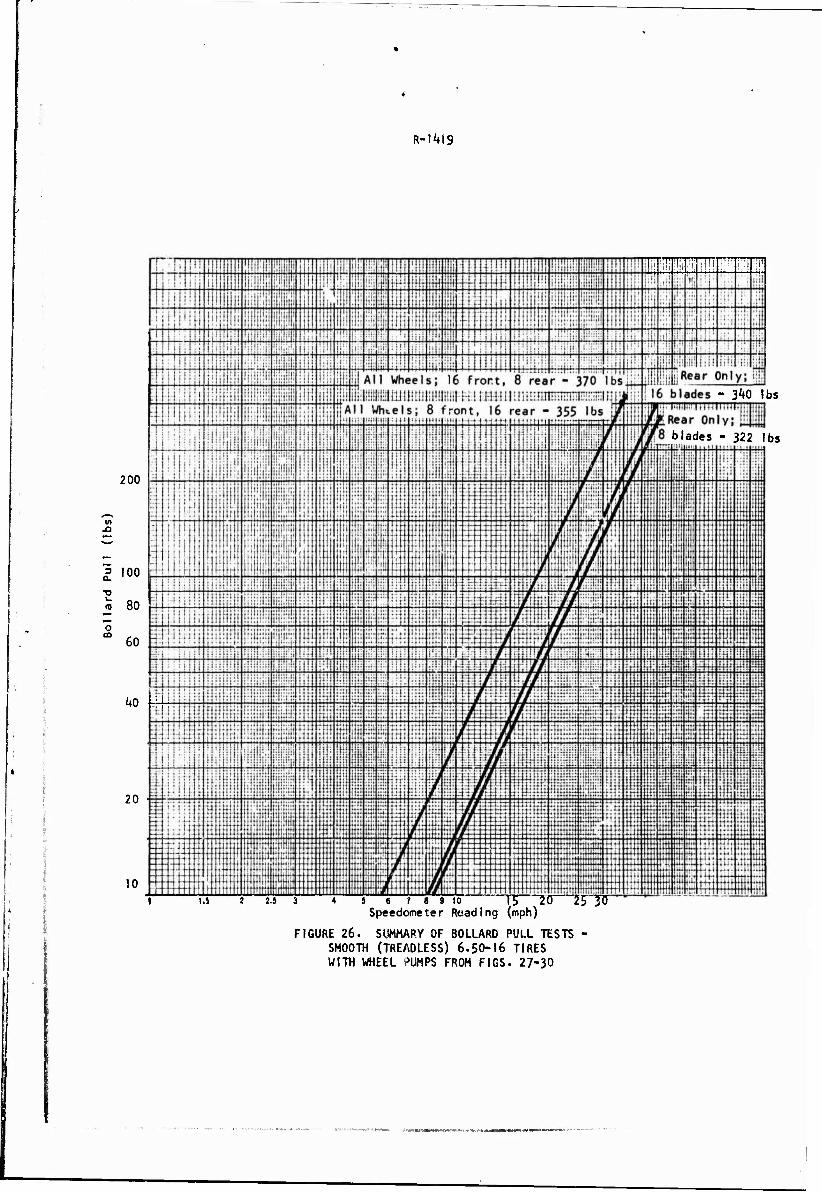
Figure 26 summarizes bollard pull tests (Figs. 27-30) in which
smooth, treadless tires (6-50-16) were fitted in place of *:he military
tires. Included in this test series were runs in which the 16-blade
pumps installed on the rear wheels (Figs. 27 and 29) were interchanged
with the 8-blade pumps (Figs. 25 and 30) normally fitted to the front
wheels. The effect of the number of blades was minor, but the effect
of the elimination of tire tread was appreciable. This reduction of power
absorption by the tires, and, hence, the release of more power to the pumps,
increased maximum thrust to the 320-370 pound range. The change in thrust
characteristics resulting from the tire change is shown in Fig. 31«
As an indication of the power absorbed by the tire tread, tests w^re
made at wide open throttle on an M15I in the water ciannel at the Land
Locomotion Laboratory- Table li shows the results of these tests along
with estimated delivered engine power calculated from the published power
train characteristics also shown in Table II-
Tests in which the stationary reaction collectors were crudely
altered to decrease their outlet area by 50 percent (Fig. 32) are summa-
rized in Fig. 33; backup data are in Figs. 3^"36. In this test series,
In addition to testing four-wheel drive and rear-wheel drive (only),
front-wheel (only) drive was tested. Figure 37 shows that, in the bollard
pull tests at least, the front and rear wheel pumps behaved independently,
with the rear pumps and tires performing with some 30 percent greater
efficiency. In Fig. 33» performances with full and 50 percent outlet
areas are compared. The results indicate that the original outlet area
(approximately 80 sq- in.) was near optimum for the designed power
loading from the viewpoint of bollard pull.
Maximum thrusts recorded in these tests occurred at different wheel/
wheel-pump speeds (here recorded as indicated speedometer speed) and in
several gears. They thus also correspond to somewhat different net power
available to the wheels. An approximate correction was made for this by
estimating the nominal gross power available for each test from the pub-
lished power train characteristics- The results of these calculations
are summarized in Table III in which pounds of static bollard pull/gross
horsepower are shown for each maximum pull developed during the test series.
10
yftfeififr'iiiiMm HITMiililB'm'il.ii'i" JiJfoV'lHHfllllJ^ ■WWOWIWM—ma

R-1419
TABLE I I
Drive Gear
1
Maximum Speedometer
Speed (mph)
Equivalent Wheel Speed (rpm)
208
Equivalent Engine Speed (rpm)
6150
Estimated De! Ive red Powe r (hp)
2-wheel 18 11
2 28 324 5340 32
3 21 324 2800 56
4 24 278 i44o 32
4-whee1 1 18 208 6150 11
2 20 232 3820 61
3 20 232 2100 '+5
4 15 17** 900 20
PUBLISHED POWER TRAIN CHARACTERISTICS
Engine: 141«5 cu. In.
71 hp @ 4000 rpm
44 hp @ 1800 rpm
Tire: 7-50 x 16 NDCC (665 rev/mi.)
Transmission ratios: 1-00 1.674, 3-179. 5-712:1
Transfer ratio: 1:1
Axle ratio: 4.86:1
11

R-1M9
U..1.1 LU'uwiLJW-.i-TT—^r^y'^v?*.!: '■
I i-
a. O X >«. — «/>
Z |
3 o
1 I +J c fA o 1 1 i 1 1 • 1 L, f—
ll
L. o (0 -tf VO OA CM J 1 i 1 1
CM —
L. 3 00 VO -* o • 1 i 1 1 • • u. -# IM
4-1 r VO <.! 1 1 i 1 1 • 1 u .—
C u. 41 > X
*J • *■
Q L. L-
2 z Q A3 o rA r-> o vO £ 1 1 • • t • • ■— </l fA :A CM CM
41 P- I 0. 3 V.
3 tn r-~ tT\ — 0 1 1 • • 1 • •
LL. CM CM CM
c o L.
, ! 1 l 1 VO • CM
1
u.
L, CM 10 o\ LA CM rA fA O CT\ •*— 0)
CC -d- LA fA fA fA fA
L. 3 ► > J- CM 00 •tf ■* en o
LL LTl IA fA fA fA fA
« * SN O O O O o 0 U-\ N z Z Z Z z > z
o z
(A *J 41 41 c *J PM »™ 41 U C C c »- ■— *~ C
*■> o o o ro 3 3 o JC z z z ft. U. LL. z CO
L. 1C VO 00 vO vO vO VO
l/l ä •■• •""■ ■"" "■" "* Q. 4*
§ c o
Q. <-> c o
z CO vO 00 00 00 00
u (MB
UL
^ Ä VO vO
l/> •"■ i£ 1
V o o D O L. IA o o u
M» X • o K VO i/i r>» z
!2
T'jiS»*^S'&>-. ' »tfe^iÄäSSSäMSg**»*«'**^

PBOTmm^m^fm^.
R-1^19
Free Running Tests
The M15J mounted In the raft was towed at various speeds by an
auxiliary boat as shown in Flc'Jre \k- The compression reading on the
load cell during towing indicated the force required to propel the
vehicle at the measured speeds hence the drag of the vehicle. Figure
38 shews a plot of load cell push vs measured water speed (curve A).
When the vehicle was allowed to propel itself, the load cell exerted
a force on the raft (its drag) which was measured and also plotted on
Figure 38 as curve B. The sum of the two (curve C) indicates the com-
bined drag of both the jeep and the raft and also indicates the approxi-
mate thrust the vehicle was generating at each measured speed- Extra-
polating curve C to obtain the thrust generated at the maximum obtained
speed (2.7 mph) yields approximately 135 lbs of thrust. This value
projected on an extrapolation of curve A yields a predicted vehicle
(only) speed of 3-2 mph, which is close to the 3-0 mph measured
when the vehicle/raft system was being towed by the boat; the jeep
was operated at wide »pen throttle; and the load cell measured no force
between the raft and the vehicle.
Table IV is a presentation of the maximum speeds achieved at
free running condition (jeep and raft) with the vehicle powered, not
towed by the boat.
During the free running tests it was apparent that increased
vehicle control was obtained with the wheel pumps. Although not quanti-
tatively measured, the turning radius was materially reduced and the
response to steering input greatly improved.
Tests» conducted later (October 1969) at Houghton, Michigan with the wheel pumps mounted on a floating version of tht Ml51 yielded a maximum vehicle speed of 3-2 mph.
13

R-]l+19
1 c *- 1 u (u > a) I 1 1 1 1 — 0£ 1- 1. o a CM
I/) a §5 ■sD vO a. o • 1 1
u. CM CM
c «- -C V <0 f~
*J > V 1 1 • 1 Q •- S. CM vz 1- OvOO
^— V in — a 5 n r*>
a. o 1 1 • 1 u. CM
o Ul i_ —1 C (0 r^ o c\ _l 4i m 1 • • • UJ > C£ CM CM CM 0. •— o ~ u K CM O a. «Ma
i Ml "> u. a u — —i §g VO LA Jf -*
UJ • • • • UJ to ^1
a- u. CM CM CM CM
CO 1 < H £
CO V
£ N
O z 2 O z Ul
a o UJ z UJ a. in
VI 4-> 4J »"■
l_ in VI u *•" ._ 01 V ID 3 j* :£ >■ a. U. v>
i_ t/l JD vO 00 \o 4» OJ .~ «— ■o cE ID •— in
L. 4) 4-1 *J c c: o 00 ^o CO 0) u —
«J u.
JZ ! VI 4-t
4) o u i_ i CJ
M o »- 1/) z
u
ysfaj» 4» as&#m**<**»****^-'e*iM''

I* ■'■
R-1419
SUMMARY OF RESULTS
The data obtained In the test program indicates that the maximum
bollard pull obtained using toe wheel pumps with standard tires (230 pounds),
Is less than the 350 pounds predicted at the start of this program. The
maximum thrust obtained by the pumps when operating with smooth tires
(370 pounds) is closer. For standard tires alone, the maximum bollard
pull was 13^ pounds.
Test reports by Ford Motor Company indicates that a Ml51 with a
simple flotation hull will travel 2.2 mph when propelled by its tires only.
On the present test rig, with military tires and the wheel pump, the
maximum free running speed (with the raft attached) was 2.4 mph; with
smooth tires, the rig could obtain 2.7 mph; with military tires and the
nozzle attached, it could obtain 2.4 mph.
While towing the rig and powering the jeep, i^e load cell read
near zero when proceeding at 3-0 mph.
The wheel pumps materially improved vehicle control while afloat.
15
R-I4I9
CONCLUSIONS
The results of the test program Indicate that the wheel pump
Is able to generate considerable thrust, though not as much as ori-
ginal ly predicted*
The parasitic drag of the tire treads seriously degrades the
performance of the pump.
The high hydrodynamic drag of the Ml51 and the steep slope
of the resistance curve (approximately at the 2.5 power) Indicate that
large increases in output by use of more power or improved efficiency
will be required before this de\<ce will propel the M151, as presently
designed, at a speed much higher than 3 mph. Alternatively, the hull
of the vehicle must be redesigned to improve its drag characteristics.
The present design was optimized for maximum bollard pull
(thrust at zero speed). Optimizing the pump for maximum speed may
enable It to travel at only a marginally higher speed in view of the
statements contained in the preceding paragraph.
The improved control generated by the wheel pumps may be
more important a factor than the marginally improved speed, since
a major problem of wheel-propel led floating vehicles is steering
control.
16
: - . „..»:.

. i
I* i-
R-I*4l9
RECOMMENDATIONS
1. That the wheel pumps be mounted on a standard military
vehicle built to operate afloat (such as the M561 or the
M656)to determine its operational characteristics.
2. That a design effort be initiated which would enable the
vehicle to take advantage of the power absorbed by the
tire treads. A sketch of such a concept is shown In
Fig. 39-
3- That further design studies on the collector be conducted
to yieH greater thrust in the vicinity of 3 mph.
17

R-1419
ACKNOWLEDGEMENTS
Tha authors wish to acknowledge the help of Messrs. J. Roper
and J. Mercter who did most of the theoretical calculations-
18
■.,.= ^.tfm^WWm***'»***»*»' -•^*1*«t^.^-^,%^fe^^.^[

■'-— ■'—" ■■-" i IM ■pummopr ■npni i""
I R-1419
REFERENCES
1. "£-Ton Truck Flotation Studies," U.S. Army Tank-Automotive Command, April 1965.
2. Rymlszewski, A. J., "Improving the Water Speed of Wheeled Vehicles," Journal of Terramechanlcs. Vol. 1, No. I, 1964.
3« Van Manen, J. D. and Oosterveld, M.W.C-, "Analysts of Ducted-Propel I er Design," SNAME Transactions. 1966.
4. Ehrlich, I. R., Kanin, I. 0. and Worden, G., "Studies of Off-Road Vehicles In the Riverine Environment, Vol. I, Performance Afloat," DL Report 1382, October 1968.
5. Betz, A«, "Introduction to the Theory of Flow Machines," Verlag 6« Braun, Karlsruhe, Germany, 1966.
6. "Ordnance Corps Equipment Data Sheets," Department of the Army TM 9-5OO, September 1962.
<■ 1

' ■ ' ) \ liWB^^I^rwt ■■ i IMP—mmmmw»—■—w ■I"1» ■
R-1419
(I
' i
FI CURE I. EARLY WHEEL PUMP CONCEPT SKETCH

r R-1M9
O C
0 • tf^
// 4
,<'&oV 0
O
il 0
//
/ / * '# 1
CM
O
II
J
1 N
j
^ >7 * 0«)' '1 / * 0 //7> .V
/
0
t>
j
1 I
SH
IP
SCR
E
1
1 1
•» ÜJ
_1
C.O.Q-.
£ ,*■
•5-ia. < a X
«
«V " 0. a
?' 1
0 s*
to
z: ■2- _i .<.
<
/ *
f *s* _CL.
SI Z) Q-
—O. -J
O
X
c
II 0- f, 4 fjf A//^
-0" 1/
I
jft
o
O J"
-I«
— rk — <-. O1
X
«X)
o
o
CM
o
■o
a to
o tu a to
O
-3" O o
a: o Lu
LU - • >
- - . o aw >■ LÜ I— <-> lil F z Z X LU LU UJ t—
< o o z o a Lu Lu
Li. Ll. O O LU LU LU
LL. O F I— — 1/1 o (J >- LU -1 UJ h to a. a. — coo u. o
< o to -a. —i
UJ < to < o z
O LU oo-o: Lu z a < LU < LU a. en - to - ^
-av to
Ü -FV Lu tO < Z -h ULU o z LU LU O U 0 Z — tO O — Lu — LU
Z LU < LU LU LU IU O LU LU .£. O 3 O < F O LU LU OO 00 LU LU Z
OCT X < Z Z3 <J > O to F Q — l/> < < I— LU X 30c 1 cc
a. to o LU 10 Lu OC </> o
O C£ to O U LU
• — 3 r*> or: LU —1
< X < LU :> F >
r*7Z£iüJli "I u ' D 'J3iau)e\Q 01 j pads L 1.» 7» J
oc o 2
f u3 ,1
B IW«te:*»»««ä*Ä!*-.

.lllUII|il!ll!!l!MW>>
R-1419
FIGURE k. EIGHT- AND SIXTEEN-BLADEO PUMPS FMPLOYED DURING THE PROGRAM
l
FIGURE 5- AN EIGHT-3LADED PUMP MOUNTED ON THE M15I ir-TON TEST VEHICLE

■I1'.- .'J ^»r-.-^.SIK.."■_!?• ■■'" '_'" '" " —'■'wy ■•—~
R-I419
FIGURE 6. WATER COLLECTOR MOUNTED ON VEHICLE (SIDE VIEW)
FIGURE 7- WATER COLLECTOR MOUNTED ON FRONT SUSPENSION (FRONT VIEW)
g, ,- ,-. .,; .i.<!^lw:^«S&i^**&***"*»* — - > *-- ■ .-.:. U .

R-1419
FIGURE 8. WATER COLLECTOR MOUNTED ON FRONT SUSPENSION (REAR VIEW)
FIGURE $. RECIRCULATING TANK TEST STAND USED TO M, ASURE PUMP OUTPUT AND EFFICIENCY

wpi ■ i —m—«wmwwimi in I nwi»i»»n 11 TO '" -r*" " " " '! " ^T-""
R-lMy
Q Z <
z
o
UJ
o
z
1 a
x o
ä 3 u
« ^* c u. o> c
UJ
«MMUHMi^v- ^.»fcwH^kÄ-J»^^

ni«i« min iHiiuinu*« rwrr^». ***mmmm>
R-1419
FIGURE II. TEST VEHICLE MOUNTED IM SUPPORT RAFT
FIGURE 12. LOAD-CELL CONNECTION BETWEEN TEST VEHICLE AND SUPPORT RAFT

wUNI^«K5£cr'H?1 5."V!."T.;TTi" '.^■'.■m;,V^ —
R-l Jt*19
FIGURE 13- VEHICLE DURING OPERATION, SHOWING SUPPORT CABLES
tat iuM>ri*iii»n'nii'»" '" " KWfti-Ä-fVi»,..

R-1419
FIGURE Ik. SCHEMATIC OF TEST VEHICLE/SUPPORT RAFT ARRANGEMENT WHEN TOWED BY BOAT

R-1M9
BOnraHtHBmY T-rr'
iMI^^
200
- 100
o. ■B 80
I 60
U0
20
10 s « 7 8 9 10 15 20 ?5 30
Speedometer Reading (mph)
FIGURE 15. SUMMARY OF BOLLARD PULL TESTS - TIRES ONLY WITHOUT WHEEL P'JMPS FROM FIGURES 16-19
^gmgggg/gS^BS^MK/uvttmmamm—i -- *««-4WW4ft wa-»-«i^i^W»„«i^K--vJ''. *mn».i*mma&a

RIV.IWLL m
R-I4I9
200
in -O
-100 3
Q.
80
o 60 00
/*o
20
10 2.5 3 5 8 7 8 9 to 15 20 25.30
Speedometer Reading (mph)
FIGURE 16. BOLLARD PULL TESTS - FOUR WHEEL DRIVE, NO WHEEL PUMPS, 7-50-16 NDCC TIRES, NO SKIRTS
R-1M9
'1111!':' TTTTT1
hi ii
ÜH4
mit
200.
in -O
., 100 3
"O L. I»
80
^T7
ill mm lull
liill
1 Tt-ttt lliii
rnrr;,. if! II
II iyli
jllj iii
l::!;;
Üüüi;:
ili'i ::t: i
TTTTTTTTlTTi1
H
!!!!
ti
rr
-umi H Ml! !
!i!:
nrrrrn Hill
+H- 133 lbs <£> 12" Displacement:
-_J
'1
£ 60
Uo
20
10 J 6 7 8 9 io 15 20 25 30
Speedometer Reading(mph)
FIGURE 1?. BOLLARD PULL TESTS - FOUR WHEEL DR!VE, NO WHEEL PUMPS, 7-50-16 NDCC TIRES, SKIRTS
MflMgfljMMBBflBWBWs www* - «*-* :K^rJi^(^^^il*,i*»a^«tfk*tf *»s«^ .t««,^,!,,. t^-

mn—m in jtiiiiiiiiiniiuiiiiiiiii i wwipimp—ppi vm**rnmmsmmm
R-1419
200
V)
_ 100 3
L.
80
o 60 m
40
20 -.--
10 4 3 6 7 8 9 10 15 20 25 30
Speedometer Reading (mph)
FIGURE 18. BOLLARD PULL TESTS - REAR WHEELS ONLY, NO WHEEL PUMPS, 7-50-16 NDCC TIRES, NO SKIRTS

s SB 7S1TK1 XEZEEZSBXBSa E
R-1419
♦ J 6 7 8 9 tor 15 20 25 30 Speedometer Reading (mph)
■IGURE 19- BOLLARD PULL TESTS - REAR WHEELS ONLY, NO WHEEL PUMPS, 7-50-16 NDCC TIRES, SKIRTS
iMiiiKtoiī*^^^

R-I4I9
200
V)
3 100 a.
I 80 o CD
60
40
20
10 5 6 ? 8 3 10 15 20 25 30
Speedometer Reading(mph)
FIGURE 20. SUMMARY OF BOLLARD PULL TCSTS - TIRES W'TH WHEEL PUMPS, FROM FIGS. 21-24
**■***• *ma&ffl

R-1^19
-1-- *- -+H-H- -H- il ■+rt-1rtt1' ' - + -■ W tw» rm 4tt>+■■»•■ 4 *+tt tHt mt IIP—H44- 111' HI '""[ n i: i i —rfr*
200
J3
älOO O.
m 80
£ 60
itO
20
10 S J 8 8 10
Speedone'-r Reading
FIGURE 21. BOLLARD PULL TESTS - FOUR WHEEL DRIVE, WHEEL PUMPS. 7.50-16 NDCC TIRES, NO SKIRTS
fejpiM: m* «SOB«»" -- ..»-«-«--,. „,, JiiV ♦..^,i-^-,;^Äi

R-1419
200
1 100
L. 10
&
Hm***- U..;t... i+U..u..t.
i 8 0 >0 Speedometer Reading (mph)
FIGURE 22. BOLLARD PULL TESTS - REAR WHEELS ONLY, WHEEL PUMPS, 7-50-16 TIRES, NO SKIRTS

R-1M9
Ill mm HI,
ii in
200
in
3 a.
&
I
1 ' t III
Mil
W* pit
TTVTl
; ! I : ;
Q I! : i 111
.V': I
I lit fffti!!
250 lbs @ 12" Displacement:
8 7 a 9 10 Speedometer heading
iliffllli ,20 25 30
tmph)'
FIGURE 23- BOLLARD PULL TESTS - FOUR WHEEL DRIVE, WHEEL PUMPS, 7-50-16 TIRES, SKIRTS
t£t ^^lä^ij^^äi^f!^^ 'iijwms^*'^*1******-'*-9''™''-**™--™-
R-\k)S
200
«1
3 100
T3
w 80
«g 60
ko
20
10 4 s e f 8 » io 15 20 25 30
Speedometer Reading (mph)
FIGURE 2k - BOLLARD PULL TESTS - REAR WHEELS ONLY, WHEEL PUMPS,
7.50-16 NOCC TIRES, SKIRTS
->T»ÄJ1K.' J*^^-J^*üJ

R- 1^419
5 8 7 8
Speedometer Reading (rnph) 25 30
FIGURE 25. CHANGES IN BOLLARD PULL PERFORMANCE USING THE WHEEL PUMPS
-:i*««P«4»(**-sö:*MaÖ.>«<-«« «»•
R-HM9
200
I 100
* 80
o CD
60
ko bR4
20
10 5 i i i I io "T5 2~0~
Speedometer Reading (mph)
FIGURE 26. SUMMARY OF BOLLARD PULL TESTS SMOOTH (TREADLESS) 6-50-16 TIRES WITH WHEEL PUMPS FROM FIGS. 27-30
WTB
340 lbs
blades - 322 lbs
TFri!!|!l!||^iltiTnnTrv

R-IM9
IIS!» Utilllilw J"^i#iiU*t ' I i ■' I ■■■■ r !:•! :-i:: -i1— mi!77|T;-iiiTTT\&MM PTflTiM iHiMlMl::iii:
200
100 ■D
* so
60
20
10
F 16
ffiiffi e 7 8 9 to 15 2 0 25 3C
Speedometer Reading (mph)
IGURE 27- BOLLARD PULL TESTS - REAR WHEtLS ONLY, -BLADED WHEEL PUMPS. 6-50-16 SMOOTH TIRES, NO SKIRTS
$ ;»^'Ä^«?:ÄS^S«to^«ca»«a*-*iW«.» '■' ' - ■•-•»■■■A, iii*

R~]k)9
m »flilfilllM
200
3 100 a.
80
60
kO
20
</ V f V * IV I 2
Speedometer Reading (mph)
FIGURE 28. BOLLARD PULL TESTS - REAR WHEELS ONLY, 8-BLADED WHEEL PUMPS, 6-50-16 SMOOTH TIKES, NO SKIRTS
*V. '*Urt«)i'U**.V ^-JMtJWWHf» «1"M ■"■ ■»

R-1M9
200
in
ü 100 a. T3 80 (D
CO 60
40
20
10
. illjll 1 TTIMfl i| S N i!|il! i'i |!ii lijl IM; mi Ilii liljiiii Tf'n'ii , , n ,,|j|,,|; TFT : i.!
ülUiti ; Ü j ifillii 'iiii 1 |!|!|! W Ui-I ill: in : .ni (H+H-fH-tH {|;I;■i■ •
1 i j ,|:.. ,..; in; Ilii ' :i
■■■\\m\\ ! iiiüi 1 |||ij.!|! ! ; 1 Id ilii i!': iiii irlt ■'■ ■
In; ■ |: tijiti i ! 111 ill; !i!;ii:!: 'i;::!l:. iili
#l|i ■ h>:i ■|! Iii1!;": jll |ij 1 I||I ijli II:: |1,1 ■|| ilii
itji iiii i i i; r' i '< '< 1 M HI
; i 1 ;',;
- . ! 1 1 1 i : 1 1 | ill h: . ;i, i ' i ;!ii
iiii ;';; III, \>\> j !
= '-!|! i 1 |f l"i 'M'i !!$!•;'! i |i|| ii
: Jill i if j if Ijitj' ifi:' • ii ill! II,: !f;i|[iij . ■ j 1
r± — — ~r — .ill
:i'
:; H1 [ü hi itliljlli |!j;i|||i i II II iiii Ijij :ii: UM ill I;1; ■ii-
^'t'l-fl'-i ■ Ifi i ' 1 lfilt|!i I'i'niP
ii |T|'|
I1 i! ;iij if :.;!
!,!' it: :h
: | fjj ilii i! 355 lb:
325 lbs
, (a) 12" Displacement 1
Displacement i)f
♦!: ■; :
:= 11 ; |;! 1 lit} Mi ■ it"
ft rfn
'! i|i! If i
|!:i i|(l i|,i l|i fill iiii @ 20" il;
•i:l il ". Iiii !ili 1 !! i
• i ; 1 i 1 1 : 1 11 Hi! iiii 1:1!
■
■Hi : : i 1 : i.;
rtt. IrirfiN : i l i.: t i , l
■ f : ' i ! ! 1 i i 1 ' ,
viijlllji I till il III!
,i !,! 1
1 ,i i! |t l.j i
ill ij!'
'ill i; ■ i ;;ii .!.' : 1 j I 1 LI ,'
■• ;!ii:iii
iiilH ill;
:i:; iii. lip : i n,i
: iljjjj, 1 Ht iiliHIl
| il 1 Uli ] l/itjll
ji;lii;i: || ii ii|i It 1 l! i: ! I
iii I ;! 1 ■i:: I'll
iiii
ill ('•I 'H1 ill ij: ill
Uli- !
1 lH r rit ' y .::l;ii;.
MM
1 1 lill
ilji ill!
;|;; Ii i:l; 1 l
i,[j
:;:: ill- It i 1 |i i;::
..j.
: i''|+( ■
! i! Il i PI 'Ii!
tiltjlij; j ii! i ii \ iitli'ir r
1 ! Ill
|ili
Hi
i|,i
i'li iiii lü'
ill
•lii [ 1 1.
ii i'i,'
i ill1 IM i
!;: ! t!
iiii
111-
-iir -i i
■; i i 11; i t-i
j I ;i' -ft i!;
t
I" 1 -i
|H lit!:'*
m) ii:;;/
if; i' i. i ii! i'i;
jit •If; 'ill (.; i '-in
||l'
1 ill.
i ; i
.1,'!
til,
ii
il
;;l; III it ilii —11-
I'I' .Hi
itll ,!i.
|i;l i|'i i'i'
iii
i||
.III 1 ,1
iii'it : 1 nHMipjuji illlJlji: | i üi ijji l!:i/::
T I'i!;!!1 Iff lpP{|! .jüi./li |
ij!1 ii/iil;
I rj ' | li{ij |H \R I ipüjiii !* i! jliiii !j|i ! iiijii-i-ii /;ll;;i: <''.'.
' ii' ,. i 111 :;.! -IffMl i
:. i! :u ; $fj|i:#:i Ifii ft f, M UP ill . i:li ml ;::;::::: :::: ■ ,;::
= ! :!:i!i! i'i ilii! I;1!:''!- -: •* ii! = l^-'lil iii ̂ .f!!;, . 1 t : : j:; i M - - I j : : 1 • ! !lt !.jl •Ii: L-k'/iii mU\m Uli ==l=IJi=-
; ;;!;;;; ::i: i
Mmmil füll is •;,';; . "\,: :l: lijl I;:: ::.:
\§\\','",\ , ;;::
wm\ it!?! ilii .ti.|. itimi'i :.;:,:M I: ■! .i'li '! m lit; !•■
!!,■ ::i| fetttit ';::::::: i'i: iiii
: ' K : ill ■Ii ! !.!: f-!. | f | j i [; ' i ; .
£Ü'i|i!:r.ji jjj !»•;■ "V Ij |[[| i;.
:'■'■.
Hiiiiiii ii !•:• ::i i ••!::■:'•:
ii imdlr] 1 Sii-fUl 111 tj j|
i* t,f(
.:;■ !;-•-; n1 il}] It It'll :ii:::ii: iiii iiii iii;
.... '"[
... i
f ■ i:' ttii % ij(i[
fin II Ii! 11 Hi I
SU5! [j V' i i a ij;;:: i ftf
1 Iii: t|ti
| 1 ail iili s jrr
I il hi
ti
lit rrf i:- 1
l.||4...l
.!•.•-..- >'il
iiii if t*
i:l!
•iii ■
i tti llWhti T IT i i.i z 2 ^ 3 t ) j 1 j ) t 0 1 5 2 0 2 i i 6 '
Speedometer Reading (mph)
FIGURE 29- BOLLARD PULL TESTS - ALL WHEEL DRIVE, WHEEL PUMPS,
NO SKIRTS, 16-BLADED PUMP IN REAR
SÄ«*^.*SBBKdBfc*»^»^^^ "

»1-1*19
7 6 9 10
Speedometer Reading (mph)
FIGURE 30. BOLLARD PULL TESTS - ALL WHEEL DRIVE, WHEEL PUMPS, 6.50-16 SMOOTH TIRES
NO SKIRTS, 8-BLADED PUMP IN REAR
:. UlWdWro-itt «M

R-IM9
200
i 100
» 80
o CD
60
1*0
20
10 i 6 7 8 9 so 15 20 25 30
Speedometer Reading (mph)
FIGURE 31. BOLLARD PULL TESTS - EFFECTS OF TIRE TREAD ON THRUST
£wm*&wmm^^m^;--.i*mMmi>*»~ » ■«■ *mm*immmmm:

R-I419
FiGURE 32. COLLECTOR WITH 50% EXIT RESTRICTION NOZZLE

R-1419
iTaStSS^^TTTTTT-'™ i:.''T'.' T£T VT-"'"'—:
Mlll^^
wmm 20 25 30" « 7 8 9 10
Speedometer Reading (mph) FIGURE 33- SUMMARY OF BOLLARD PULL TESTS
EFFECT OF 50% REDUCTION IN EXIT AREA, FROM FIGURES 20, 3'*. and 36

WM i ii wsmmwmmm lit"" 1 1 ■ !
R-1419
200
in -Q
3 100
JE 80
o m
60 = =
40
20
10 7 8 9 10
Speedometer Reading (mph) FIGURE 34. BOLLARD PULL TESTS - FOUR WHEEL DRIVE,
WHEEL PUMPS WITH 50% EXIT NOZZLE, 7-50-16 NDCC TIRES, SKIRTS

«wnnw iiiiwiHi nimm BIDKir flHl ,■ XT-W3*rcKVTT,,HEHE,fl'ilis< O'j* "5 s--';r.i;-!-?ra!t™Tfir'n:«.r^:"Tv "•' '
R-lH)S
5 8 7 8 9 10 15 26 25 30 Speedometer Reading (mph)
FIGURE 35- BOLLARD PULL TESTS - FRONT WHEEL DRIVE ONLY, WHEEL PUMPS WITH 50% EXIT NOZZLE, 7-50-16 NDCC TIRES, SKIRTS
I •
aMMWW JWMMM—WWW—

MUMM
R-I«tl9
200
in -O
£ 100
ä
OTT ff»^ Mi i!iilill;Hnlli
7 $ 9 10 Speedometer Reading
FIGURE 36- BOLLARD PILL TESTS - REAR WHEEL DRIVE ONLY, WHEEL PUMPS WITH 50% EXIT NOZZLE
7-50-16 NDCC TIRES, SKIRTS
a<WM»fliffE**W»»

■" in i—i in — ■-— uu»»»»inii rammtmm rnmnm ■C1BW—IWWB8I -.11I 1IHHHJWW"PI
R-1^19
200 -
V)
i,0° a.
■o 80 m
I 60
40
20
10
!: ! Pill! i. i rn mr: ■ 1" ■ ■'. iiiiliiiiiiii/--'
: 1 ii'i i.i
rrr 111 rr, TTT ii:1!;'!; ! :ll'i: !::'!' :: j! TTT?
II
1 ; : !i : j 'I'M liijiiil; 1 —
.
iiiii;!') rlll.ll
!tiiil:! l:i:
..... i ; : i j i: ,! ijij ; ; ; i '; ■
- 1 lit jii'llili i1"" '': Iljülj!: ■ I *■'
|!t 'ih 4-li, • — i
i -- — —- ..... -~ • ■ Ijjiiij'
i!'il[! 1 i 1 i! !! ili-jii
r~" —:r ;-.;
r~
--■
;- - —- — ■- rr- .... ~ T~ -- ■llilm! i:i|i!:!!
km jjUjji! !;.;i:!.:|
:- —••- ! ■
r:; .... :- ■1"
„.
ii-.. pi ■ ; i i i' | ' ' •
I
--.- ■■-- — ~: ------- ~: :':
— •- •— ■—
..- — 1 iii; : i
'32 lbs
i { 1
ni!i!;i hiii j:i;;:;!
'. ', '!':;; • I 82 lbs
170 1bs •111 iiii • i-:i 1 I
' 1 ! > > i : I hid.:
ii|F!' ::r:;:,
. . ! i '■/■'
::ii . . : 1
"J'
lii .... .,., ill' lili lili
ill 1 i..
i ; 1 iii; !M iii:
1 1 Iiiii iij! ■ i l_
i '■ i 1 I : ; . lüi'Üjl Hip;;!:
• ■
i
jjjiiüi! i
\\\m i: tltit! 1 : 1
!;! i
I ' ' : ' . ■ ,
-:— — •-- -- —' / : ■ 'lJ_''
|M;-. >i 1 J- c liiiiiil! ■ ■ 1 . i
■— •— . ■ -
-~ -,.!' . • '■ ^/ </ \J: <$. ■
liiWiiii "•— •
;:".:: — — —
/ V y * 0i\
■! ! Mi; i ; ■ i *■.;■;: iii;
(•'I!! i ■ . ■,. ■ 1 . i
... 1 i :; j i lii i
itj ; i j 1!: I-..- Ji'
= ■ 1 • i I i I' Iiiii
■ i . . < . I
:i. • ; ■ t ; - | i ■ ■■ ■ f ' 1 :::::::-!
a. 1 Hi
11 ii .. 11 •"•'/•■'
it i ifi-ijii
|il!::ii: f !ir:;ti;! ::!::i;:;
:::;
1 t i 2 2 s i i s i 1 1 > i Ü i< L^M^J
3 2 5 3 0 Speedometer Reading (mph)
FIGURE 37- SUMMARY OF BOLLARD PULL TESTS - EFFECT OF PUMP LOCATION, FROM FIGURES 3*+"36

■TM1IIWH» W—WH1WW1 ■*!" ' <'"*" — ——W «WH
R-!<tl9
200 ~
«1
»-^ ai c 100
•o (U 01
80 .— ^— 01 o
60 •o ID 0 _I
f. ; ■
- •
40
20
10 - 9 to T5 Speed (mph)
FIGURE 38. FREE RUNNING TESTS
11' ll> WHH.W HH 11*11 III L,»H

SB t-JStat - sq • XT' rr a
R-1M9
2 a:
< Q.
a < UÜ
h- h- 1/)
LU =>
— (J M — — X —I Ui
i=> 3 Q
LU Ü. > O O
cc x a.
b£ UJ to >
Q- X UJ <_> o<
0C 3
BBBffl—— a. —M» «BWHWMHWBBaWIBHBW—' ■——»"■»■»'■«—■ «MIUMMtiMMgKjtj

m i MI i ■ iwin—ll < PWHUIMR
UNCLASSIFIED Siriifiiv Cl.isslfiriihnn
DOCUMENT CONTROL DATA .R&D >'-rtififi cli,\-ijfirntton of title, hotly of nhvtteirt owl htdtithtfi n* notntltm ..u*t br «nttrrd whrn thv overoU report N r/»«. *}tlril)
OMiGtNArtNC »CTivtTV fCoijiur«*« on that)
DAVIDSON LABORATORY STEVENS INSTITUTE OF TECHNOLOGY CASTLE PQ.NT STATION. HOBOKEN. N. J. 07030
i».p»tro«T iccUHirv cu»»»if ic * HON
UNCLASSIFIED lb. anovP
i »r.PO»t TltLt
PRELIMINARY STUDIES OF A WHEEL PUMP FOR THE PROPULSION OF FLOATING VEHICLES
4 DCICRI»TIVC NOtt) (T>p« of report tndjnclualvt dalt-t)
FINAL 5 AUTMOAIII fulfil .laiot, mlddlQ Inlllmt, liniuini)
I. Robert. Ehrlich and C J. Nuttall, Jr.
« »E«J(II DATt
DECEMBER 1969 »». CONTRACT ON OUANT NO.
DAAE07-68-C-2608 b. PROJECT NO.
7«. TOTAL NO. OF PAOKt
19 + 59 fig». »6. NO. or Hen
•«. omoiNiton'i aironr NUMSCMIII
REPORT NO. 1419
tb. OTHin NtPONT NOlil 7ÜJ5 orfiar numb«rt SÜT5 mar b* (••t«n»rf IM« nporl)
10. OKTNISUTION ITATCMCNY
DISTRIBUTION OF THIS DOCUMENT IS UNLIMITED
II. SUPPLCMCNTARV NOTfcf
1. ABSTRACT*
II. S.ONIOHiMO MILITARY ACTIVITY
U. S. ARMY TANK-AUTOMOTIVE COMMAND
A nove' propulsion device for an amphibious wheeled vehicle Is described. This device, which Is an Integral part of the vehicle wheels, pumps water between the tire rim and the braledrum Inboard Into a stationary collector which turns th*s water rearward, thereby generating forward thrust.
Results of preliminary tests conducted on a stationary pumping system and when mounted on a MI51 £-ton truck are presented.
Tests Indicated that the device increases the maximum bollard pull approximately 100% and the maximum speed approximately M)% over propulsion with tires alone. It also materially Improves the con- trollability of the vehicle.
DD.T..1473 ,PAGEn
S/N 0101-807-661)
UNCLASSIFIED Security CUaairtcalion »-JK6»

J.H*.!-.'. .■- .'. ' ".■' "". T..--W:--- :-
z o o in _l T3 „J
■o c 3 C H3 ID CL O cc CL
ID
o
0- o cc a. 0
o
■5 Ul x > T3
■5 Ul o> >
0) £ CC 4J 4J
.2 cc 4-J
0 E
4J
o r^ . O i o r^ • E O
u_ 5 1_ -5 § ._ 14-
o u. s -5
O 4J
• CL
5 —1 - ON
VO ON <
3 *->
O- X 3
on
_i
ON vO
3 <
C 3
in CL O ■— 1 1/1 l/l O- Q , ON JiC l/l c 10 -X •— c ID ^~ c "■■ —I *J
L, a>
§ u a> a
C _l 4J ID Ul • 4-1 <0 4-- ul m 4-> L. £ 4->
c V >
4-1
in
Ul
< a.
ID C
iZ
3 Z
• ->
t—
CO E o t vO < <vj
c
o o
T3
l/t c a) > UJ 4-*
m
Ul
< u.
ID C
IZ
3 Z
«
•
e u 01 o
>■
co E o < vO CM •
c I 3 O o
o o (_> 1 * o o O i in w en o m in - or» vn ON o t/1 in Ul — ub i • ■— >- o l/> Ul Ul) i •
QC r>. ÜJ _l -* CO -3 -C cc r^ Ul -1 -5 CO -3 x: go 2 .
— o o — E x t— Ul L.
-C u Ol
1 <u l^.-C O -M
4->
»4-
0
— o o —
r- Ul u
• m ON
VO 1 01
O 4-1
4-1
>4-
o c» -> to > O 1_ vt-
ON f»N
L'J o -> (/) > o u ■r- Ul CO
3* >- O U Z < r
Q. Ul
w
2o Ct U.
C o 4-1
CO
32 >• 13 CC 5T < —
Q. 01
CC Ul
4->
ON o->
IS a v-
c o
4-> z - o c
Z r- — < -5 a» + 4J -a
U 0) 3
-O z - o c
Z H ~ < ■5 01 + 4J X!
U ft) 3
X)
SJt a: o L. -Q (D L •— in a» X O i_ JO ID L- — -j <0 o • L. fl) 1_ a -* — _J ID o u S_ ro 1_
^ 9 -1 u. o> a: Q. 4J a 4-> — o -J u. 0) cc Q. 4-> O. 4-J > X! Ul V) c 01 VI > JO Ul V) c o) l/l < o DC U. Ü • ON o i- •— < o CC u. 01 • ON o *- O X a. o Q: O CL o Q X CL O CC O CL a
z z o o "™ H-
in —i 3 a. o cc CL
■o c •D
u
in _i
CL o cc a.
c ID
O
• Ul • • Ul 0) . ■5 x $ 01 -5 f > T3
0) .*» •— 4-1 01 4-> 4-1 r- cc 4-» •— p cc o
o o u. 5
• L. ->
i o
_E 14-
o o u. 5 s
4-1
I a. CN 4-1 c CL (*N 3 c
•M 5 ^. ON vO ON
3 <
3 4-1
X 3 _l
* ON < 1
3
c CL Q "iü 1 1/1 l/>
c a. Q
(D ON C l/l
•" -1 4-1 *~ C _j 4-> ^~ ID Ul • 4-1
(1) XI
s u o> a
m 4-1 Ul . 4J H 4-1 in Ul -~-s 3 H c l/> Ul ^^ 3 1_
01 XI
e u 01 o
c c
> 5 C
Z
CO E § c
> 5 (0
c
Z
00 E 0» < • «■ -> O C o 01 < •— —> o < Ü 4-} Ü- vO < o 4-1 u. VO o m
o u. o *■—*"
O 1 • ■a in
o u. o *~*
O <N • i in
-o « m m en «j in in - t*N 10 ON o l/l
>- o l/) UJ ^ u!> i • •™ >■ o in ui UÜ i • tc r^ Ul —J .* 00 => J: cc r^ Ul _l 1? 00 => x: go — o
Q — ^ ■5
vO 1 <u
4-> P° — o Q —
vO 1 01
4J
2 . 2 x F tu
«-I . <n Ol
t^ SI O 4J
»4-
O s . r- u.i 4-> L. in
O 4-1 14-
o o -» in > O L. Ul o -> in > 0 L. Ol Ul
03
2z >- C3 XT Ul
*4- 3o c o
00
22 >- o
Q. 01
x: Ul
«4- So" c o cc 2: OC
ON rN
a >«- — cc z CC ON a vi-
z • zP JZ 4J L. 4-1 -o
*-> 3 Z * IP -C
4.' 1_ *■> "O
4-<
3 o c £2 o 1_ Ü + u a»
(0 l- _o o c
Si — < r o
u L. Ü + U 0)
ID L. XI
... _j ID Q • L. ID L. — _J ID O • L ro l_
>i? -J u. 01 cc a •w a 4-1 — 0 -J u. 01 CC a «J a 4-1
2u W C V 1/) > -O Ul l/V C 01 l/l < 0 01 • ON 0 i- • — < o cc u. 01 • ON o <- o z CL o CC U CL o Q X CL O CC O CL a
«.>.*■* «KSi^kas^itt

r Scrurüy rHyCTimnlririllon
K(Y .VOAOI
Amphibians
Swimmers
Floaters
Propulsion
DD/r..1473 «BACK, 1/N OIOI-I07-J4JI
UNCLASSIFIED
Sacurlly CIcieWlcallon »•it«Ot
!****»»