complex phenomena uni ed simulation research … 12. complex phenomena uni ed simulation research...
TRANSCRIPT
Chapter 12
Complex Phenomena UnifiedSimulation Research Team
12.1 Members
Makoto Tsubokura (Team Leader)
Keiji Onishi (Postdoctoral Researcher)
Chung-gang Li (Postdoctoral Researcher)
Leif Niclas Jansson (Postdoctoral Researcher)
Rahul Bale (Postdoctoral Researcher)
Tetsuro Tamura (Visiting Researcher)
Ryoichi Kurose (Visiting Researcher)
Gakuji Nagai (Visiting Researcher)
Kei Akasaka (Visiting Researcher)
12.2 Research Activities
The objective of our research team is to propose a unified simulation method of solving multiplepartial differential equations by developing common fundamental techniques such as the effectivealgorithms of multi-scale phenomena or the simulation modeling for effective utilization of the mas-sively parallel computer architecture. The target of the unified simulation is supposed to be complexand combined phenomena observed in manufacturing processes in industrial circles and our finalgoal is to contribute to enhance Japanese technological capabilities and industrial process innovationthrough the high-performance computing simulation.
Most of the complex flow phenomena observed in manufacturing processes are relating to or cou-pled with other physical or chemical phenomenon such as turbulence diffusion, structure deformation,heat transfer, electromagnetic field or chemical reaction. While computer simulations are rapidlyspreading in industry as useful engineering tools, their limitations to such coupled phenomena havecome to realize recently. This is because of the fact that each simulation method has been optimizedto a specific phenomenon and once two or more solvers of different phenomena are coupled for sucha complicated target, its computational performance is seriously degraded. This is especially truewhen we utilize a high-performance computer such as K-computer. In such a situation, in additionto the fundamental difficulty of treating different time or spatial scales, interpolation of physicalquantities like pressure or velocity at the interface of two different phenomena requires additionalcomputer costs and communications among processor cores. Different mesh topology and hence datastructures among each simulation and treatment of different time or spatial scales also deterioratesingle processor performance. We understand that one of the keys to solve these problems is to adoptunified structured mesh and data structure among multiple simulations for coupled phenomena. As
96
Chapter 12. Complex Phenomena Unified Simulation Research Team
a candidate of unified data structure for complicated and coupled phenomena, we focused on thebuilding-cube method (BCM) proposed by Nakahashi[1].
[1]K. Nakahashi, High-Density Mesh Flow Computations with Pre-/Post-Data Compressions, Proc.AIAA 17th CFD Conference (2005) AIAA 2005-4876
12.3 Research Results and Achievements
12.3.1 Development of a unified framework for large-scale multiphysicsproblems
Based on the Building Cube Method (BCM), we have developed a unified solver framework CUBE(Complex Unified Building cubE) for solving large-scale multphysics problems. The framework hasa modular design where CUBE provides a core library containing kernel functionalities e.g. a mesh,flow fields and I/O routines. Solvers are then developed on top of the kernel by connecting necessarykernel modules together, forming a solver pipeline, describing the necessary steps to solve a particularproblem.
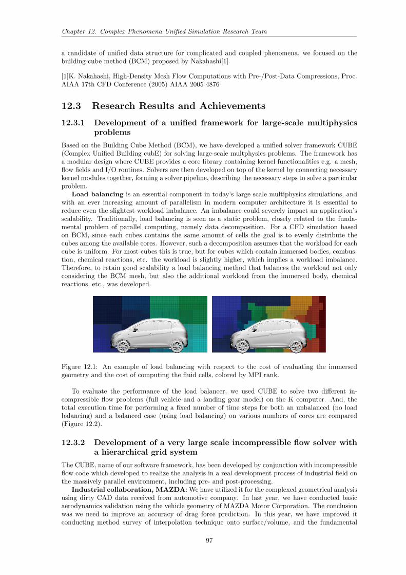
Load balancing is an essential component in today’s large scale multiphysics simulations, andwith an ever increasing amount of parallelism in modern computer architecture it is essential toreduce even the slightest workload imbalance. An imbalance could severely impact an application’sscalability. Traditionally, load balancing is seen as a static problem, closely related to the funda-mental problem of parallel computing, namely data decomposition. For a CFD simulation basedon BCM, since each cubes contains the same amount of cells the goal is to evenly distribute thecubes among the available cores. However, such a decomposition assumes that the workload for eachcube is uniform. For most cubes this is true, but for cubes which contain immersed bodies, combus-tion, chemical reactions, etc. the workload is slightly higher, which implies a workload imbalance.Therefore, to retain good scalability a load balancing method that balances the workload not onlyconsidering the BCM mesh, but also the additional workload from the immersed body, chemicalreactions, etc., was developed.
Figure 12.1: An example of load balancing with respect to the cost of evaluating the immersedgeometry and the cost of computing the fluid cells, colored by MPI rank.
To evaluate the performance of the load balancer, we used CUBE to solve two different in-compressible flow problems (full vehicle and a landing gear model) on the K computer. And, thetotal execution time for performing a fixed number of time steps for both an unbalanced (no loadbalancing) and a balanced case (using load balancing) on various numbers of cores are compared(Figure 12.2).
12.3.2 Development of a very large scale incompressible flow solver witha hierarchical grid system
The CUBE, name of our software framework, has been developed by conjunction with incompressibleflow code which developed to realize the analysis in a real development process of industrial field onthe massively parallel environment, including pre- and post-processing.
Industrial collaboration, MAZDA: We have utilized it for the complexed geometrical analysisusing dirty CAD data received from automotive company. In last year, we have conducted basicaerodynamics validation using the vehicle geometry of MAZDA Motor Corporation. The conclusionwas we need to improve an accuracy of drag force prediction. In this year, we have improved itconducting method survey of interpolation technique onto surface/volume, and the fundamental
97

Chapter 12. Complex Phenomena Unified Simulation Research Team
Figure 12.2: Comparison of runtime per time-step for balanced and un balanced cases for the landinggear model (left) and the vehicle model (right)
investigation of approximate domain method on immersed boundary (IB). The difficulty was camefrom the uncertainty of front/back face of complicated geometry because the interpolation causedhuge error if the search of face orientation has been missed. It was highly depends on the complexityof geometry and grid resolution. The method which is drawn by the analogy of Poisson solverproviding a front/back face information based on flow solution has been developed. Then we couldsuccessfully get a reasonable absolute drag value (about 2% error), and drag delta between 2 differentaerodynamic configurations. At the same time, we could successfully reproduce the characteristictotal pressure flow field comparing to wind-tunnel measurement data.
Figure 12.3: Overview of computational grid and flow field (MAZDA Motor Company).
Table 12.1: predicted drag on 2 configurations normalized by experimental base case.Cd Exp. Sim.Base 1.000 1.021Aero 1.011 1.043∆Cd 1.15% 1.46%
Industrial collaboration, SUZUKI: The usability on the practical use of industrial applica-tion has been evaluated by discussing with professional engineers of automobile company. we havecorroborated with SUZUKI MOTOR CORPORATION to do this work. We have provided CUBEto them with simple documents and training, and they have evaluated by their own way, and gaveus their feedback report. The geometry preparation time has been accelerated from 35 hours usingcommercial software to 2 hours using CUBE framework, based on dirty CAD data. The estimateddrag coefficient between 2 configuration had better agreement with measurement than commercialcode. It shows CUBE is already ready for usage in the actual design process in term of the usability,human-cost, accuracy, and turn-around time. But, they had a strong request to improve calculationtime because their process has a limitation to finish each job within 1 night whereas our method
98

Chapter 12. Complex Phenomena Unified Simulation Research Team
requires 2 or 3 days. To say more, their method is based on Reynold averaged approach based onstrong turbulence model which is known to have relatively large error, our method is based on thepure transient approach which generally requires 10 times larger calculation resource comparing toRANS. After the discussion, we have agreed to improve it in near future because it is very importantto know the true needs on the field of industrial engineering. As the first step of that, we havedeveloped a new function to enable us to use local refinement grids in the grid generation software.It can reduce the calculation load about from 1/5 to 1/10 for the vehicle case, to accelerate thesolution. And the implementation and testing of the local refinement functionality for IB has beenstarted in this year. We thinks it also can lead to the enhancement of effective multi-grid method(MG), or adaptive mesh refinement method (AMR) in the future development scope.
Both of MAZDA and SUZUKI could decide to promote the results inside their organization, andcontinue the current research activity using our software in FY2016 by submitting the applicationand accepted the industrial use project on K-computer.
Figure 12.4: Overview of characteristic flow field (SUZUKI MOTOR CORPORATION).
Table 12.2: predicted drag on 2 configurations normalized by experimental base case.Condition CUBE Commercial Code AFinest grid size 2.0 [mm] 2.0 [mm] (layer 0.04[mm])Num. of cells 400 million 53 millionFluid Configuration LES (Standard Smagorinsky) DES (SST k-ω)Num. of timesteps 145,000 4,000CAD prepare 8 hours 8 hoursPre processing time 2 hours 34.5 hoursParallel num. 4,096 cores (K-computer) 512 cores (Intel Xeon)Flow computation time 258 hours 8 hoursPost processing time 1.5 hours 1.2 hoursError of Cd prediction Applx. 10% Applx. 11-16%Error of ∆Cd prediction 8% 12%
Wind HPC consortium: At a research activity on Wind-HPC consortium which is organizedby Tokyo Institute of Technology and several Japanese major construction companies, the detailedturbulence characteristics on wind canopy of actual urban area geometry that has housings, buildings,vegetation, and street, and so on, has been investigated. And, the academic case validation usingsquare cylinder has been conducted. The results shows reasonable accuracy, so both of results hasbeen published in the paper of architecture design. This research will continue on the FLAGSHIP2020 project of priority ] 4 regarding wind environment evaluation for building construction on severeclimate condition through next years.
12.3.3 Development of unified compressible flow solver for unified low tomoderate Mach number turbulence with hierarchical grid system
The Simulation of the low speed compressible turbulence is a key challenge for the industrial applica-tions such as combustion, aeroacoustics and significant heat transfer phenomena. Roe scheme with a
99

Chapter 12. Complex Phenomena Unified Simulation Research Team
Figure 12.5: Pressure field in Shiodome area(50m Height)
Figure 12.6: Pressure field in Marunouchi area(50m Height)
Figure 12.7: Q-criterion (Q=0.0015) in Shiodome area
Figure 12.8: Q-criterion (Q=0.0015) in Marunouchi
low-Mach number fix [1] is adopted to tackle slow flows with variable densities. An immersed bound-ary method (IBM) for compressible flows with a fast, easy to implement and robust interpolationmethod is developed to handle the complex geometries.
Basic Validation with Academic case: Based on the experiments conducted by Jia andGogos [2], a steady-state natural convection around a heated sphere under the condition of that,the Grashof number based on the radius of the sphere is 104, is conducted to validate the unifiedsolver. Fig. 12.9(a) shows the contour of the velocity magnitude. The entrainment comes fromthe bottom of the sphere which is consistent with the description by [2]. Fig. 12.10 shows thetemperature contour. Above the top of the sphere, higher temperature region is formed, which causeworse natural convection near the surface so the velocity in this region is quite low. Comparisons ofthe averaged Nusselt number (Nu), drag coefficients caused by pressure and viscous are tabulated inTable 12.3. The results are in good agreement with the experimental data and show the accuracyand availability of our program for dealing with the complex geometry and heat transfer problems.The present results have been published in [3].
The simulation of a sphere at Re=104 is performed to investigate the availability of the unifiedsolver for higher Reynolds numbers. Fig. 12.11 shows the distribution of mean pressure coefficient.The result is well consistent with the [4] and the separation angle can be also accurately captured,
100

Chapter 12. Complex Phenomena Unified Simulation Research Team
Figure 12.9: A heated sphere: velocity magnitude (m/s)
Figure 12.10: A heated sphere: temperature (K)
which is around 86 degrees.Fig. 12.12 shows the Q criterion contoured by the magnitude of the velocity. The turbulence
structures are mainly formed after the separated shear layers generated from the separation point.Besides, the transition from large to small turbulence structures can be also clearly observed in thewake region.
Figure 12.11: Sphere flow at Re=104: Distribution of mean pressure coefficient
Table 12.3: Comparison with existing experimental dataN̄u CD,p CD,u
Exp. [2] 8.74 0.46 0.62Present 8.77 0.46 0.59
101

Chapter 12. Complex Phenomena Unified Simulation Research Team
Figure 12.12: Sphere flow at Re=104: Q criterion
Finally, the simulation of the whole vehicle demonstrates the capability of the unified solver.Fig. 12.13 shows the contour of the velocity magnitude. The development of the boundary layeron the front window and roof can be clearly observed, which shows the capability of unified solverfor handling the complex geometry. Besides, the flows penetrate the front of the car to the engineroom is also obviously shown, which indicates that our immersed boundary can also treat non-watertight geometry. Fig. 12.14 shows the history of the drag and lift coefficients. After reachingthe quasi steady state, the average vales of them are good agreement with the experimental data.This is an indication that the unified solver is also able to obtain accurate results for this kind ofpractical application. In Fig. 12.15, the Q-criterion contoured by the magnitude of velocity is shown.The development of turbulent coherent structures near the wheel, mirror and side windows is wellcaptured. In addition, the typical turbulent structures-hair pin can be also obviously observed onthe roof.
[1] F. Rieper, Journal of Computational Physics, 230 (2011) 5263-5287.[2] H. Jia, G. Gogos, Int. J. Heat Mass Transfer 19 (1996) 1603-1615.[3] C. Li, M. Tsubokura, Int. J. Heat Mass Transfer 75 (2016) 52-58.[4] C. George, S. Kyle, Physics of Fluids, 16 (2004) 1449-1466.
Figure 12.13: Vehicle Simulation: Snapshot of velocity magnitude
12.3.4 Development of high performance moving boundary solver for re-alistic motion
Aerodynamics of Vehicle in a turn: The aerodynamic performance and stability a vehicle isstrongly influenced by the crosswinds during cruise and while in turning maneuvers. It is difficult tosimulate such real-world flow scenarios in wind tunnel experiments. Furthermore, it is also difficult tomeasure unsteady aerodynamic forces in wind tunnel experiments. Thus, it is desirable for numericalmethods to be able to efficiently and accurately simulate such flow conditions. To this end, here, wepresent simulation of a vehicle (the complex full vehicle geometry discussed in the previous section)undergoing a turning motion, including wheel rotation and turn, chassis roll and turn, in a uniformflow. This simulation the result of a collaborative work between Mazda Motor Corporation andRIKEN AICS. The detailed vehicle geometry and it motion data were provided by Mazda, and thesimulation was carried out at on the K-computer using CUBE. The Lagrangian-Eulerian approach
102

Chapter 12. Complex Phenomena Unified Simulation Research Team
Figure 12.14: Vehicle Simulation: Time series of drag (left) and lift (right) coefficients
Figure 12.15: Vehicle Simulation: Snapshot of flow structures extracted by the Q-criterion
developed during the previous year was used for this simulation. As mentioned above all the vehiclemotion, except linear translation, is imposed on the vehicle. If the linear translational motion wasimposed on the vehicle, a fine mesh would be needed in the vehicle’s path, which makes the meshsize excessively large. An alternate approach, where instead of imposing the linear translation on thevehicle it is imposed on the entire mesh, was used. In this approach the vehicle’s center of gravityremains fixed relative to the mesh. So, the fine mesh is needed only in a small region around thevehicle instead of the region of the vehicle’s path. This reduced the mesh size by a factor of 3-5.The results of the simulations are shown in Fig. 12.16.
Figure 12.16: Flow field around a vehicle in a turn. (Left) Velocity magnitude on a horizontal plane.(Right) Iso surface of swirl.
Aerodynamic performance of a Ski jumper: Ski jump is a popular winter sport and is apart of winter Olympics. It is one of the sports in which Japan is competitive and has some of thebest ski jumpers in the world. Ski Jump is a sport where aerodynamic interaction of the jumper and
103

Chapter 12. Complex Phenomena Unified Simulation Research Team
air plays a key role in outcome of the sport. Minute changes in an athlete’s posture can go a longway, literally. The distance covered by an athlete is strongly correlated to the drag and lift forceson the athlete while in air. And, these forces are greatly influenced by the athlete’s posture. Incollaboration with Prof. Keizo Yamamoto of Hokusyo University we investigated the aerodynamicperformance of two of Japan’s top ski jump athletes, Haruka Iwasa and Sara Takanashi. Throughthe unsteady aerodynamic simulation of the two ski jumpers we analyzed the evolution of forcesduring a short period before and after the jump from the ski ramp. During this period the jumperchanges from a sitting posture to a standing posture. Our analysis revealed that the posture andmotion of Haruka Iwasa lead to lower drag force and higher lift force compared to the forces on SaraTakanashi. This is consistent with the real-world performance record of the two ski-jumpers.
Figure 12.17: Evolution of flow around Ski jumper Haruka Iwasa during a jump. (Left) Startingposture of the jump. (Right) Final posture of the jump.
12.4 Schedule and Future Plan
(1)Five-year objectives and goals toward 2017
• Construction and development of the simulation technology for bringing out the performanceof K-computer
• Proposal of the technological trend of HPC simulation toward EXA-scale
(2)Long-term objectives
• Establishment of the research and development center for industrial simulation technology
• Contribution to computer science by expanding the developed simulation technology to differ-ent fields
(3)Time schedule
12.5 Publications
Journal Articles
[1] Yuki Horikoshi et al. “Die design for deep drawing with high-pressured water jet utilizingcomputer fluid dynamics based on Reynolds’equation”. In: Journal of Materials ProcessingTechnology (2015).
[2] Chung-Gang Li, Makoto Tsubokura, and Rahul Bale. “Framework for simulating natural con-vection in practical applications”. In: International Communication in Heat and Mass Transfer(2016).
[3] Chung-Gang Li et al. “Compressible Direct Numerical Simulation with a Hybrid BoundaryCondition of Transitional Phenomena in Natural Convection”. In: Journal of Heat and MassTransfer (2015).
104

Chapter 12. Complex Phenomena Unified Simulation Research Team
[4] Jing Li, Makoto Tsubokura, and Masaya Tsunoda. “Numerical Investigation of the flow arounda golf ball at around the critical Reynolds number and its comparison with a smooth sphere,Flow”. In: Turbulence and Combustion (2015).
Conference Papers
[5] Hirotaka Ishioka et al. “Coupled 6DoF motion and Aerodynamics Simulation of Road Vehiclesin Crosswind Gusts”. In: 33rd AIAA Applied Aerodynamics Conference, AIAA 2015-3308,pp.1-10, DOI: 10.2514/6.2015-3308 (22-26, June, 2015, Hilton Anatole, Dallas, TX). 2015.
[6] Jing Li et al. “Large-eddy simulation for golf ball aerodynamics: The effect of surface roughnesson the drag crisis and the Magnus effect”. In: Proceeding of the ninth international symposiumon turbulence and shear flow phenomena (TSFP-9), 7D-4, pp.1-5(June 30-July 3, 2015, TheUniversity of Melbourne, Australia). 2015.
[7] Takuji Nakashima et al. “Unsteady Aerodynamics Simulations of a Sedan-Type Road Vehicleduring Sinusoidal Steering Input”. In: 33rd AIAA Applied Aerodynamics Conference, AIAA2015-3307, pp.1-12, DOI: 10.2514/6.2015-3307 (22-26, June, 2015, Hilton Anatole, Dallas,TX). 2015.
[8] Yoshihiro Okada et al. “Analysis of Wind Turbulence in Canopy Layer at Large Urban AreaUsing HPC Database”. In: Aerodynamics Evaluation of Road Vehicle in Dynamic Maneuver-ing”, 2016 SAE World Congress (12-14, April, 2016, Cobo Center, Detroit, Michigan, USA).2016.
[9] Tetsuro Tamura et al. “Analysis of Wind Turbulence in Canopy Layer at Large Urban AreaUsing HPC Database”. In: 9th International Conference on Urban Climate (20-24, July, 2015,Toulouse France). 2015.
Invited Talks
[10] 坪倉誠. リアルタイム・リアルワールド自動車統合設計システムにおける粒子法への期待.Prometech Techno Forum 2015 in NAGOYA. 2015.
[11] 坪倉誠. リアルワールドシミュレーションが拓く新たな自動車空力. 日本自動車技術会2015年春季大会フォーラム. 2015.
[12] 坪倉誠. 京からポスト京へ 大規模CFDが拓く新たな応用空力シミュレーション. 第29回数値流体力学シンポジウム. 2015.
[13] 坪倉誠. 自動車周りの非定常空気力解析. 日本機械学会No.15-33講習会. 2015.
105

Chapter 12. Complex Phenomena Unified Simulation Research Team
Posters and Presentations
[14] Rahul Bale et al. Immerserd boundary method in a multiphysics framework for large scalesimulations. 27th International Conference on Parallel CFD, (May 17-20, Montreal, Quebec,Canada). 2015.
[15] Niclas Jansson. Towards large-scale multiphysics simulations on the K computer. BIT Circus2015 , (August 26-27, Umea Sweden). 2015.
[16] Niclas Jansson and Makoto Tsubokura. Dynamic Load Balancing for Large-Scale MultiphysicsSimulations. 第29回数値流体力学シンポジウム, 博多 日本 2015.
[17] Hidenori Kawai et al. HPC-Based LES of Wind Flow Over Large Urban Area with SlightUndulation. ECCOMAS Congress 2016, (June 5 - 10, 2016, Crete Greece). 2016.
[18] Chung-Gang Li, Tsubokura Makoto, and WuShung Fu. An Investigation of Transitional Phe-nomena from Laminar to Turbulent Natural Convection using Compressible Direct NumericalSimulation. 3rd International Workshop on Heat Transfer Advances for Energy Conservationand Pollution Control, (October 16-19, 2015, Taipei,Taiwan). 2015.
[19] Chung-Gang Li and Makoto Tsubokura. A New Program for the Application of Natural Con-vection in Practical Products. Twelfth International Conference on Flow Dynamics, (October27-29, 2015, Sendai, Japan). 2015.
[20] Chung-Gang Li and Makoto Tsubokura. A New Simulation Framework for the Natural Convec-tion in Practical Products. American Physical Society 68th Annual DFD meeting, (November22-24, 2015, Boston, USA). 2015.
[21] Chung-Gang Li and Makoto Tsubokura. A Unified Simulation Framework for Low Speed Com-pressible Turbulence in Industrial Applications. 28th International Conference on Parallel CFD,(May 9-12, Kobe, Japan). 2016.
[22] Chung-Gang Li and Makoto Tsubokura. An investigation of transitional Phenomena fromLaminar to Turbulent. 15th European Turbulence Conference 2015, (August 25-28, 2015, Delft,Netherlands). 2015.
[23] Chung-Gang Li et al. A Unified Simulation Framework for Compressible Flows at All Speedsin Industrial Applications. 第29回数値流体力学シンポジウム, 福岡 日本 2015.
[24] Keiji Onishi and Makoto Tsubokura. Parallel Computation of Sliding Mesh for the Unstruc-tured Grid Finite Volume Method on the Rotating Wheel Vehicle Aerodynamics Simulation.28th International Conference on Parallel CFD, (May 9-12, Kobe, Japan). 2016.
[25] Keiji Onishi, Makoto Tsubokura, and Takashi Kamioka. Practical Full Vehicle Multi- PhysicsAerodynamics Simulation for Engineering Design Process Using Large-scale Parallel CFDFramework. ECCOMAS Congress 2016, (June 5 - 10, 2016, Crete Greece). 2016.
[26] Bale Rahul and Makoto Tsubokura. Lagrangian-Eulerian based immersed boundary method forlarge scale simulations. BIT Circus 2015 , (August 26-27, Umea Sweden). 2015.
[27] Bale Rahul et al. Constraint Based Immersed Boundary Method for “Thin” Structures. 28thInternational Conference on Parallel CFD, (May 9-12, Kobe, Japan). 2016.
[28] Bale Rahul et al. Lagrangian-Eulerian based immersed boundary method for large scale simu-lations. 第29回数値流体力学シンポジウム, 博多 日本 2015.
[29] Bale Rahul et al. Scalable Immersed Boundary Method for Large scale Simulations with MovingImmersed Structures. ECCOMAS Congress 2016, (June 5 - 10, 2016, Crete Greece). 2016.
[30] Tetsuro Tamura et al. High performance computation by BCM-LES on flow and pressure fieldaround buildings. 8th International Colloquium on Bluff Body Aerodynamics and Applications,(June 7 - 11, 2016, Boston USA). 2016.
[31] Tetsuro Tamura et al. LES for wind turbulence in canopy layer at large urban area. 68th AnnualMeeting of the APS Division of Fluid Dynamics, (November 22-24, 2015, Boston USA). 2015.
[32] 大西慶治, 坪倉誠. Dirty CAD形状を意識した自動車空力シミュレーション手法開発. 第21回計算工学講演会, 新潟 日本 2016.
[33] 大西慶治, 坪倉誠. DirtyCADデータへ対応した並列IB-BCMによる自動車空力シミュレーションの実用性評価. 第29回数値流体力学シンポジウム, 博多 日本 2015.
106

Chapter 12. Complex Phenomena Unified Simulation Research Team
[34] 大西慶治, 坪倉誠. irtyCADデータへ対応した並列IB-BCMによる自動車空力シミュレーションの実用性評価. 第29回数値流体力学シンポジウム, 博多 日本 2015.
[35] 赤坂 啓, 藤山 祐司, 大西 慶治 and 坪倉 誠. 自動車操縦安定性および空力性能の連成に関する非定常空力解析手法の構築. 第2回「京」を中核とするHPCIシステム利用研究課題 成果報告会, 東京 日本 2015.
107