component design specification for the mit multi-threaded …ajax/mtx/cds_part1.pdf · component...
TRANSCRIPT
Data General / MIT . . ConsortiumData General / OMRON / MIT . . Consortium
Component Design Specification for the MIT Multi-Threaded X WindowSample Server
Mike Haynes Hiroya ChibaPaul Layne Akio HaradaRick Potts Hidenobu KanaokaJohn A. Smith Takayuki Miyake
Data General Corporation Omron Corporation62 T.W. Alexander DriveResearch Triangle Park, NC 27709 Kyoto, Japan
in association withMIT X Consortium545 Technology SquareCambridge, MA 02139
Version 5.0April 15, 1993


Permission to copy, modify, create derivative works, and to distribute this document and copies, modifications and derivative works thereof, is hereby granted without fee, provided that the copyright legend hereafter stated and this notice appear in all such copies, modifications and derivative works, and that neitherthe name OMRON or DATA GENERAL be used in advertising or publicity pertaining to distribution of any such copy, modification or derivative work without specific, written prior permission of the party whose name is to be used.
This work is provided “as is”. The Authors do not warrant the accuracy, completeness or utility of this work, and disclaim any liability arising from reliance upon it. No representation or other affirmation of fact contained in this document, including but not limited to statements regarding capacity, response-time, performance, suitability for use or performance or products, shall be deemed to be a warranty for any purpose, express or implied, or give rise to any liability whatsoever. THE AUTHORS DISCLAIM ALL WARRANTIES WITH REGARD TO THIS WORK, INCLUDING WITHOUT LIMITATION ALL IMPLIED WARRANTIES OF MERCHANTABILITY AND FITNESS. IN NO EVENT SHALL THE AUTHORS OR ANY OF THEM BE LIABLE FOR ANY SPECIAL, EXEMPLARY, PUNITIVE, INDIRECT OR CONSEQUENTIAL DAMAGES OR ANY DAMAGES WHATSOEVER RESULTING FROM LOSS OF USE, DATA OR PROFITS, WHETHER IN AN ACTION OF CONTRACT, NEGLIGENCE OR OTHER TORTIOUS ACTION, ARISING OUT OF OR IN CONNECTION WITH THE USE OF THIS WORK.
No rights or licenses are hereby granted except the limited rights relative to copyright expressly set forth above. Without limitation, no rights or licenses to any patents of the Authors are directly or implicitly granted.
UNIX is a U.S. registered trademark of UNIX Systems Laboratories.X Window System is a trademark of the Massachusetts Institute of Technology.
Copyright 1991, 1992 and 1993 by M.I.T. X Consortium, Data General Corporation and OMRON Corporation (collectively, herein, the “Authors”); all rights reserved.
A vertical bar in the margin of a replacement page indicates substansive technical change from the previous revision.
NOTICE

MTX Component Design Specification Table of Contents
iData General / OMRON / MIT . . Consortium
CHAPTER 1 Introduction 111.1 Revision History 11
1.2 Purpose 12
1.3 Major Chapter Sections 13
1.4 MTX Overview 15
1.5 Design Goals 15
1.6 Design Assumptions 15
1.7 Threads 16
1.8 Monitors 16
1.9 Abbreviations Used 17
CHAPTER 2 Main Server Thread 192.1 Overview 19
2.2 Data Objects 20
2.3 Concurrency Issues 21
2.4 Internal Organization and Implementation 212.4.1 Server Initialization 21
2.4.1.1Initialize Input Device Objects 222.4.2 Server Control: Wait On Signal to Wakeup 232.4.3 Server Cleanup 232.4.4 Extensions 232.4.5 How are other Threads Affected 232.4.6 R5 versus MTX 24
CHAPTER 3 Client Connection Thread 253.1 Overview 25
3.2 Data Objects 26
3.3 Concurrency Issues 26
3.4 Internal Organization and Implementation 273.4.1 Client Connections 273.4.2 Server Initialization and Control 273.4.3 Client Initialization and Control 273.4.4 R5 versus MTX 28
CHAPTER 4 Client Input Thread 314.1 Overview 31
4.2 Data Objects 32
4.3 Concurrency Issues 36
4.4 Internal Organization and Implementation 364.4.1 General Thread of Control 36
ii
Table of Contents MTX Component Design Specification
Data General / OMRON / MIT . . Consortium
4.4.2 Request Processing 374.4.2.1GrabServer 38
4.4.3 Client Output Delivery 384.4.3.1Flushing Output to Clients 39
4.4.4 Server Initialization and Control 394.4.5 Client Initialization and Control 394.4.6 DDX Layer 394.4.7 ScreenSaver 394.4.8 XDM Interface 404.4.9 FontServer Interface 404.4.10Extensions 404.4.11R5 versus MTX 40
CHAPTER 5 Client Output Thread 475.1 Overview 47
5.2 Data Objects 48
5.3 Concurrency Issues 49
5.4 Internal Organization and Implementation 495.4.1 General Thread of Control 495.4.2 R5 versus MTX 50
CHAPTER 6 Device Input Thread 516.1 Overview 51
6.2 Data Objects 52
6.3 Concurrency Issues 52
6.4 Internal Organization and Implementation 536.4.1 General Thread of Control 536.4.2 Communication with the DIT using a socketpair 546.4.3 Client Event Delivery 546.4.4 Event Processing 546.4.5 DDX Software Cursor 546.4.6 ScreenSaver 556.4.7 R5 versus MTX 55
CHAPTER 7 Signal Handling Thread 577.1 Overview 57
7.2 Data Objects 57
7.3 Concurrency Issues 57
7.4 Internal Organization and Implementation 587.4.1 Processed Signals 587.4.2 SHT Algorithm 587.4.3 SIGALRM Delivery 59

MTX Component Design Specification Table of Contents
iiiData General / OMRON / MIT . . Consortium
CHAPTER 8 Locking Summary 618.1 Overview 61
8.2 Locking Terminology 61
8.3 Server Objects 63
8.4 Objects protected by locks 65
8.5 Thread Lock Dependencies 678.5.1 MST 688.5.2 CCT 698.5.3 CIT 708.5.4 COT 738.5.5 DIT 73
CHAPTER 9 Resource Data Base Monitor 779.1 Overview 77
9.2 Data Objects 789.2.1 Resources 789.2.2 Resource Data Base Internal Structures 80
9.3 Concurrency Issues 809.3.1 Resource Lock Types 809.3.2 Resource Lock Modes 819.3.3 Locking Precedence 82
9.4 External Interface 839.4.1 Add or Free Resources 839.4.2 Locking Resources 83
9.4.2.1Lock Resource Individually (Generic Interface) 839.4.2.2Lock Resource Group (Generic Interface) 839.4.2.3Lock Core Resources 84
9.4.3 Extend Type or Class 849.4.4 Initialization and Termination 859.4.5 Miscellaneous 85
9.5 Internal Organization and Implementation 859.5.1 Locking Mechanisms 85
9.5.1.1Locking RDB Internal Structures 869.5.1.2Locking Individual Resources 88
9.5.2 Performance Considerations 909.5.2.1Locking Analysis 909.5.2.2Readers/Writers Lock 929.5.2.3Expanded Interface for Core Resources 92
CHAPTER 10 Pending Operation Queue Monitor 9510.1 Overview 95
10.1.1 POQ Concepts 95
10.2 Data Objects 9610.2.1 POQ Element 9710.2.2Grab Server Element 9810.2.3ConflictRec 98

iv
Table of Contents MTX Component Design Specification
Data General / OMRON / MIT . . Consortium
10.2.4ExtensionRec 9910.2.5 WindowRec 9910.2.6 Conflict Mask bits 100
10.2.6.1Read/Write Conflict Mask Bits 10010.2.6.2Exclusive Conflict Mask Bits 10210.2.6.3Misc. Conflict Mask Bits 103
10.3 Concurrency Issues 10310.3.1 POQ Monitor Internals 10310.3.2 POQ Access 10410.3.3 Conflict Detection/Avoidance 105
10.3.3.1Window Conflicts 10510.3.3.2Window Subtree Locking 10610.3.3.3Region Conflicts 10810.3.3.4Extension Conflicts 108
10.3.4Grab Server 109
10.4 External Interface 11110.4.1 Initialization and Termination 11110.4.2 Lock/Unlock 11110.4.3 Come Up For Air 11210.4.4 Grab Server 11210.4.5 Convenience Macros 112
CHAPTER 11 Device/Event Monitor 11311.1 Overview 113
11.2 Data Objects 114
11.3 Concurrency Issues 115
11.4 External Interface 11511.4.1Data Locking 11511.4.2Initialization and Termination 11611.4.3Event Delivery 11611.4.4Event Requests 11611.4.5Device Requests 11611.4.6Device Event 11711.4.7Grab Requests 11711.4.8Window Changes 117
11.5 Internal Organization and Implementation 11711.5.1Locking Requirements 11811.5.2Device/Event Access Routines 11811.5.3Implementation Alternative 119
CHAPTER 12 Message Output Monitor 12112.1 Overview 121
12.2 Data Objects 122
12.3 Concurrency Issues 12312.3.1Message States and Transitions 12312.3.2X Protocol Output Requirements 12512.3.3Meeting the X Protocol Output Requirements 125

MTX Component Design Specification Table of Contents
vData General / OMRON / MIT . . Consortium
12.3.3.1Design Features 12512.3.3.2Meeting Condition 1 12612.3.3.3Meeting Condition 2 12612.3.3.4Meeting Condition 3 126
12.3.4Message Delivery Threads 12712.3.4.1Client Output Thread 12712.3.4.2Client Input Thread 127
12.4 External Interface 12712.4.1Initialization and Termination 12712.4.2Get/Return Message List to/from Pool 12712.4.3Send a Message to a Client 12812.4.4Transfer Local Message Lists to Global Buffer 12812.4.5Flush All Messages 12812.4.6Grab Message Delivery for Client 128
12.5 Internal Organization and Implementation 12912.5.1Message Structure 12912.5.2Global Message Pool 13012.5.3Message Buffers 13112.5.4Client Output Threads 13212.5.5Grab Message Delivery Implementation 134
12.5.5.1ProcGetImage Implementation 135
CHAPTER 13 Other MTX Locking 13713.1 Font Subsystem 137
13.1.1Locking Alternatives 13813.1.2Current Locking Mechanism 13913.1.3Implementation details 139
13.1.3.1Method 2 13913.1.3.2Method 3 139
13.2 Atom Database 140
CHAPTER 14 DDX Issues 14314.1 Cursor Management 143
14.1.1Software cursor 14414.1.2Hardware cursor 145
14.2 Reentrancy 14614.2.1 miPolyArc 14614.2.2miPaintWindow 14614.2.3cfb Stipple (only when PPW == 4) 147
14.2.3.1Implementation 14714.2.4NEXT_SERIAL_NUMBER 14914.2.5Must_have_memory 150
14.3 Render Locking 151
CHAPTER 15 Other DIX Issues 15215.1 ScreenSaver 152
15.2 Block and Wakeup Handler 153

vi
Table of Contents MTX Component Design Specification
Data General / OMRON / MIT . . Consortium
15.3 Server Extensions 154
15.4 PEX 154
15.5 Security 154
15.6 Priority Threads 154
CHAPTER 16 Server Extension Writers Guidelines 15516.1 Introduction 155
16.2 Identify Extension Objects 15716.2.1Identify PEX Objects 158
16.3 Identify Inter-Object Relations 15816.3.1Identify PEX Inter-Object Relations 158
16.4 Identify Object Usage 16016.4.1Identify PEX Object Usage 161
16.5 Identify Object Locking 16216.5.1Identify PEX Object Locking 164
16.5.1.1Coarse Grained PEX Locks 16516.5.1.2Medium Grained PEX Locks 16616.5.1.3Fine Grained PEX Locks 167
16.6 Analyse Extension for Reentrancy 16816.6.1Analyse PEX for Reentrancy 169
16.7 Implement the MTX-safe design 17016.7.1Implement the PEX MTX-safe design 170
16.8 Extension Threads 173
16.9 Extension Initialization 173
16.10 Final Thoughts on Extension Design 173
APPENDIX A Data Objects 1751.1 Entity-Relationship Diagram 175
1.2 Object Categories 1771.2.1 Client 1771.2.2 Color 1771.2.3 Cursor 1771.2.4 Device 1771.2.5 DIXFontInfo 1781.2.6 Extension 1781.2.7 Event Masks 1781.2.8 GC 1791.2.9 OSComm 1791.2.10OSFontInfo 1791.2.11Pixmap 1791.2.12Property 1791.2.13Screen 1801.2.14Selection 1801.2.15Window 180

MTX Component Design Specification Table of Contents
viiData General / OMRON / MIT . . Consortium
1.3 Interrelationships of Object Categories 180
APPENDIX B Functionality Mapped to Design 183
APPENDIX C References 187

viii
Table of Contents MTX Component Design Specification
Data General / OMRON / MIT . . Consortium
MTX Component Design Specification List of Figures
ixData General / OMRON / MIT . . ConsortiumData General / OMRON / MIT . . Consortium
FIGURE 1 Structure Chart Notation 13
FIGURE 2 MTX Server Threads 14
FIGURE 3 Main Server Thread 20
FIGURE 4 Client Connection Thread 26
FIGURE 5 CCT Top Level Structure Chart 28
FIGURE 6 CCT Establish New Connections Structure Chart 29
FIGURE 7 Client Input Thread 32
FIGURE 8 Protocol Requests categorized by Object 33
FIGURE 9 Data Object Usage by Protocol Requests 35
FIGURE 10 CIT Top Level Structure Chart 41
FIGURE 11 CIT Proc Vector Logical Structure Chart 42
FIGURE 12 CIT Proc Windows Logical Structure Chart 43
FIGURE 13 CIT ProcCreateWindow Structure Chart 44
FIGURE 14 CIT CreateWindow Structure Chart 45
FIGURE 15 Client Output Thread 48
FIGURE 16 Device Input Thread 52
FIGURE 17 DIT deviceProc example Structure Chart 56
FIGURE 18 Lock Granularity for Shared Objects 62
FIGURE 19 Server Object Summary 65
FIGURE 20 Locks per object Summary 66
FIGURE 21 MST Locking Summary 68
FIGURE 22 CCT Locking Summary 69
FIGURE 23 CIT Locking Summary (INIT & NORMAL phases) 71
FIGURE 24 CIT Locking Summary (EXIT phase) 72
FIGURE 25 COT Locking Summary 73
FIGURE 26 DIT Locking Summary 75
FIGURE 27 Resource Data Base Monitor. 78
FIGURE 28 Resource and associated RDB node. 79
FIGURE 29 Core resource lock types. 81
FIGURE 30 RDB locking mechanism. 86
FIGURE 31 RDB Resource Lists. 87
FIGURE 32 Resource lockbits format. 89
FIGURE 33 Resource lock and unlock algorithms. 90
FIGURE 34 POQ Data structures 96
FIGURE 35 Processing requests on the POQ 105
FIGURE 36 Window hierarchy showing level numbers. 106
FIGURE 37 Expanding regions for packed pixel frame buffers. 108

x
MTX Component Design Specification
Data General / OMRON / MIT . . ConsortiumData General / OMRON / MIT . . Consortium
FIGURE 38 GrabServer example 110
FIGURE 39 Device/Event Monitor. 114
FIGURE 40 POQ requirements of lower level DEM routines. 118
FIGURE 41 Device Event Monitor Internals. 119
FIGURE 42 Message Output Monitor. 122
FIGURE 43 Message states and transitions. 124
FIGURE 44 Message contents. 129
FIGURE 45 Global Message Pool. 131
FIGURE 46 Message Buffer. 132
FIGURE 47 Message Delivery Algorithm. 133
FIGURE 48 Grab and Ungrab Message Delivery Algorithms. 135
FIGURE 49 Components in Font Subsystem 138
FIGURE 50 Atom Database 141
FIGURE 51 Building an MTX-safe extension 156
FIGURE 52 PEX Entity-Relationship Diagram 159
FIGURE 53 PEX Entity-Relationship Diagram 160
FIGURE 54 PEX Object Usage 162
FIGURE 55 PEX Lock Summary with Coarse Grained Locks 165
FIGURE 56 PEX Lock Summary with Medium Grained Locks 166
FIGURE 57 PEX Lock Summary with Fine Grained Locks 168
FIGURE 58 MTX-safe ProcPEXDispatch() 171
FIGURE 59 MTX-safe PEXCreateLookupTable() 172
FIGURE 60 Entity-Relationship Diagram 176
FIGURE 61 Object Category Interrelationships 181
FIGURE 62 Functionality Mapped to Threads 184
FIGURE 63 Functionality Mapped to Object Groups 185

MTX Component Design Specification Introduction
11Data General / OMRON / MIT . . ConsortiumData General / OMRON / MIT . . Consortium
CHAPTER 1 Introduction
1.1 Revision History
1.0 Initial draft version, September 6. 1991
2.0 Second draft version, January 9, 1992
• Add slight changes to the MST.
• Moved validation functionality from the CCT to the CIT.
• Add new connection validation changes to the CIT.
• Add a ticket taking scheme for message delivery to/from the COT buffers. This will integrate more fully with event processing when it is defined in the third draft ver-sion of this document.
• Completely rewrote the resource locking strategy.
• Add chapter on DDX issues (CHAPTER 14).
• Add screensaver and block/wakeup handler strategies (CHAPTER 15).
• Note: event processing may get redesigned. This redesign will be incorporated in the third draft version.
3.0 Third draft version, June 6, 1992
• Simplify the layout of the chapters.

12
Introduction MTX Component Design Specification
Data General / OMRON / MIT . . Consortium
• Add details to MST, CCT, CIT.
• COT is created dynamically.
• Complete description of message delivery and ticket taking.
• Replace Window Lock List with Pending Operation Queue.
• Event processing does not need redesign; only re-implementation.
• Change details of DDX issues.
• Add Message Object Monitor chapter.
• Add Extension Writers Guidelines chapter.
4.0 Fourth draft version, October 23, 1992
• Replace ticket taking with local message buffering
• General threads chapter cleanup.
• Rewrite all locking chapters.
• Rewrite Extension Writers Guidelines chapter.
5.0 Fifth draft version, April 15, 1993
• Bring entire document up to date with evolving design.
• Add Signal Handling Thread chapter.
• Add Font Locking sections.
1.2 Purpose
This Component Design Specification (CDS) document provides a detailed description of the major components of the Multi-Threaded X (MTX) server and shows how the MTX server will be implemented. The CDS is the third in a series of documents that will describe the MTX server. These documents follow closely the software develop-ment cycle of functional analysis, functional design, detailed design, and implementa-tion. (NOTE: in some development organizations, the CDS is also called the Detailed Design Specification (DDS).)
Although some readers may not be familiar with a software design methodology, such as Yourdon [MPJ88, Y84,Y85], we encourage you to become acquainted with these engineering tools so that you may better understand the MTX server design.
The MTX server will be provided by the MIT X Consortium as a sample implementa-tion using POSIX 1003.4a threads and conforming to the X Protocol as specified in [SG90].
The design specified in the CDS is derived from the functionality specified in the MTX Functional Design Specification (FDS). Whereas the FDS said “what it does”, the CDS will be a basis for implementing the MTX server and tell implementors “how it is done”.

MTX Component Design Specification Introduction
13Data General / OMRON / MIT . . ConsortiumData General / OMRON / MIT . . Consortium
1.3 Major Chapter Sections
Each chapter that describes an MTX component is organized into the following sec-tions. A component is defined to be either a thread or a monitor. The thread encapsulates code and dictates flow of control. The monitor encapsulates objects and dictates access control.
1. OverviewThis section presents a high-level description of the component. It explains the major functions of the component and how they generally relate to the other compo-nents of the MTX server.
2. Data ObjectsDescribes the data objects manipulated by the component. These objects can include tables, queues, lists, global variables, etc. The interrelationship of these objects is also described. The use of any locks associated with the data objects is also described.
3. Concurrency IssuesThis section explains the major concurrency issues that affect the component. These issues include thread creation/deletion, mutex locking/unlocking, and interactions of this component with other components via synchronization primitives (i.e. wait/sig-nal).
4. Internal Organization and ImplementationExplains the overall organization of the component in a detail sufficient to start cod-ing the implementation. This section describes how this component interfaces to the different functional levels (such as DIX, OS, DDX, and MI). This section also dis-cusses the MTX server implementation and how it differs from X11R5. FIGURE 1 shows the notation to be used in describing these differences. Note that double barred boxes indicate system and library routines rather than MTX server routines.
.
FIGURE 1 Structure Chart Notation
Deleted FunctionCall
New Function Modified Function
New Call ToExisting Function
pthread_create
Thread Function pthread_signal
Any Function
Condition Name
pthread_wait
Any Function
Condition Name
Mutex Nameargument

14
Introduction MTX Component Design Specification
Data General / OMRON / MIT . . Consortium
.
FIGURE 2 MTX Server Threads
DeviceInputThread
ClientConnectionThread
ClientOutputThread
ClientInputThread
XClient
GraphicsHardware
LedBell
Message Data
Device Info
Client/Resources
ReplyErrorEvent
NewConnectionData
ConnectionRequest
ClientInput
ClientOutput
Event
DeviceInput
GraphicsOutput Device
Control
Per Client
MainServerThread
KeyboardMouse
LEGEND
data flowthread create
thread
data
external object
data name

MTX Component Design Specification Introduction
15Data General / OMRON / MIT . . ConsortiumData General / OMRON / MIT . . Consortium
1.4 MTX Overview
The functionality of the MTX server will be the same as that of the current R5 sample server. Although the functionality is equivalent, the implementation is not. The MTX server will be implemented with threads and concurrency support whereas the R5 server has a single thread of control.
The current X server looks for client requests, input events, and new client connections within the dispatch code. By combining these three concurrent functions into one serial loop, the interactivity of the R5 server suffers. Using threads, we can divide these func-tions into separate flows of control. The general strategy is to not bind functionality into threads such that there is a strong inter-thread coupling. Tightly coupled threads require more code and synchronization overhead to support inter-thread communication (ITC). This additional complexity makes debugging much more difficult and reduces modular-ity.
A description of each of the MTX components and the corresponding server functional-ity they exhibit is described in the following chapters. MTX components are either threads or monitors. An overview is shown in FIGURE 2.
1.5 Design Goals
• Improve interactivity by preventing long protocol requests from locking out other clients.
• Minimize the number of threads.
• Minimize thread context switching.
• Optimize rendering performance.
• Minimize mutex usage. Contended mutexes are expensive, and acquiring mutexes requires automatic update of processor caches to maintain cache coherency.
• Don’t be lulled by the 80/20 rule. That is don’t generate a design that works for 80% of the cases, but performs poorly for the other less used 20%.
• Avoid optimizations which severely penalize unexpected server use.
• Focus on 8 and 24 bit cfb.
1.6 Design Assumptions
• Framebuffer access is much slower than the ability of a CPU to want to write to it. This bottleneck is even more apparent in a multi-processing environment.
• Support Symmetric Multi-Processing (SMP) platforms with 1 to 10 processors.
• Can modify the existing DIX/DDX interface.
• The server normally has no more than 4 clients executing requests on the server at any one moment.
• There is a small amount of resource sharing. Most Client Input Threads will use objects that are not shared with other threads.

16
Introduction MTX Component Design Specification
Data General / OMRON / MIT . . Consortium
1.7 Threads
A thread is a sequential flow of control. There may be more than one thread executing within a process. Each thread shares the address space of the process with all other threads that are created in the process. A thread has its own execution stack, errno, and thread id. The benefits to using threads are that disjoint sets of code may be executed in parallel while sharing a common code and data address space. Using threads increases the concurrency and interactivity of a process, and allows for more efficient use of mul-tiprocessor architectures.
In order to profit from kernels that support threads and multiprocessors, the MTX server will be targeted to run only on operating systems that conform to the POSIX 1003.4a standard [P1003.4a]. This standard supports
• the creation, control, and termination of threads
• the use of synchronization primitives by threads in a common, shared address space
• per thread data
Users of the X Window System who can not or do not want to use the MTX server will be able to use a single-threaded version of the server.
Note: In this document, the words input and output refer to the server’s point of view. For example, the Client Input Thread allows the server to take input from the X Client; the Client Output Thread allows the server to send output to the X Client; the Device Input Thread allows the server to take input from hardware devices.
CHAPTER 2 through CHAPTER 7 document the thread components in the MTX Server.
1.8 Monitors
Read and write access to data structures that must be shared by many threads can be effectively managed using the Hoare monitor. This programming construct encapsulates the shared data object in a protective wrapper. The wrapper enforces mutual exclusion by allowing only one thread access to the shared data object at any one moment. The monitor is a global object that advertises all of the public access routines of the object to the current set of threads.
The Hoare monitor is acceptable if the object requires exclusive access. But, it is a poor performer when there are many more readers than writers. Typically, we would like to allow multiple reads to occur concurrently while allowing only one write access at a time.
This solution to the reader-writer problem is handled nicely by the crowd monitor. The crowd monitor has guard procedures that decide when each thread may enter or leave a reader or writer access group. These guard procedures arbitrate access to the protected data object. The crowd monitor determines which group currently has access permis-sion, and queues those threads that must wait.

MTX Component Design Specification Introduction
17Data General / OMRON / MIT . . ConsortiumData General / OMRON / MIT . . Consortium
Monitors will be used where possible to control access to shared server objects.
Locking of MTX server objects is insured by accessing objects only through monitors. CHAPTER 8 through CHAPTER 13 describe this locking strategy and show the details of the MTX monitor components. In those chapters where MTX monitors are described, we discuss both the public interface and the internal design. We think that extension writers will be most interested in the public interface while server developers will be curious about the internal design of the monitor.
1.9 Abbreviations Used
CCT - Client Connection ThreadCIT - Client Input ThreadCOT - Client Output ThreadDIT - Device Input ThreadMST - Main Server ThreadSHT - Signal Handling ThreadDE - Device Event MonitorMOM - Message Output MonitorPOQ - Pending Operation QueueRDB - Client/Resource Data Base

18
Introduction MTX Component Design Specification
Data General / OMRON / MIT . . Consortium

MTX Component Design Specification Main Server Thread
19Data General / OMRON / MIT . . ConsortiumData General / OMRON / MIT . . Consortium
CHAPTER 2 Main Server Thread
2.1 Overview
The Main Server Thread (MST) manages the global MTX server environment. This thread initializes the different parts of the server and creates the Signal Handling Thread for handling process-wide signals, the Device Input Thread(s) for processing device input, and the Client Connection Thread(s) so that X Clients can establish communica-tions with the server.
If the MST receives a wakeup signal, it cleans up the global MTX server environment and checks to see if the server should reset or terminate. If it should reset, the MST rein-itializes the server environment and starts the MTX setup all over again.
The MST is required to insure that server initialization and control is localized in only one area of the server. As such, it is an implementation artifact and does not exhibit the kind of core design functionality that we see in the other server threads. Threads other than the MST, such as the Client Input Thread and the Device Input Thread, exist because they exhibit core functionality.

20
Main Server Thread MTX Component Design Specification
Data General / OMRON / MIT . . Consortium
FIGURE 3 Main Server Thread
2.2 Data Objects
Creates the following:
• Resource Database Object
• Message Object
• Device/Event Object
• Pending Operation Queue Object
• Atom Database Object
• Server Object
Initialize MTX
Environment
Cleanup MTX
Environment
ResourceDatabase
Device/EventDatabase
Pending Oper-ation Queue
MessageObject
ServerObject
AtomDatabase

MTX Component Design Specification Main Server Thread
21Data General / OMRON / MIT . . ConsortiumData General / OMRON / MIT . . Consortium
The Server Object consists of things such as the root window, window table, default font path, default font, scratch GC, scratch stipple, etc.
2.3 Concurrency Issues
When the MTX server is started, it will automatically enter the Main Server Thread and execute the initialization steps in serial order. No other threads will contend for server data objects since no other threads exist at this point. After initializing the server data objects, the MST will create threads for signal handling, device input, and client con-nection. Then, the MST will sleep until it receives a wakeup signal. Receipt of the wakeup signal indicates that the server should reset itself or terminate.
The MST will create the following threads:
• the Signal Handling Thread
• the Device Input Thread(s)
• the Client Connection Thread(s)
2.4 Internal Organization and Implementation
An overview of the MST is as follows:
mutex_t ServerMutex;cond_t ServerCondition;
MST();{
process the command line arguments (if any)initialize MTX global locksinitialize Message Output Monitorblock all process-wide signals handled by the servercreate Signal Handling Threadlock ServerMutexwhile (1){
server initializationwait on ServerCondition to wakeupserver cleanupif exit
break}unlock ServerMutexexit(0);
}
2.4.1 Server Initialization
The MST inner loop will execute the following initialization steps in order:
22
Main Server Thread MTX Component Design Specification
Data General / OMRON / MIT . . Consortium
• Perform OS dependent initialization
• Initialize the Pending Operation Queue Monitor
• Create Well Known Sockets (only once)
• Initialize the Protocol Vectors (only once)
• Initialize the Resource Database Monitor
• Initialize the Serial Number Key
• Initialize the Atom Table object
• Initialize the Device/Event Object
• Initialize output to the Frame Buffer or graphics device objects
• Initialize extension objects
• Initialize the root window object
• Initialize device input object
• Initialize and Create the Device Input Thread(s)
• Initialize the default font objects
• Display the initial cursor and root window
• Initialize Selection objects
• Create the Client Connection Thread(s) (only once)
Note that there is no need for Block and Wakeup Handlers in MTX. Since R5 tries to implement asynchronous activity in a single-threaded environment, these Handlers were needed to give the appearance that the server was waiting. In MTX, the individual threads will block; so these implementation artifacts are no longer needed.
After the server is initialized, the MST will sleep on a pthread signal. This signal will be triggered by the exit of the last CIT when it detects that there are no more clients con-nected to the MTX server, or when the server receives a UNIX signal.
2.4.1.1 Initialize Input Device ObjectsMTX initializes the Device Input Thread (DIT) state and then, just as in R5, the MTX server will make a call to the DDX function InitInput which calls AddInputDevice for each core device. AddInputDevice creates the device object and registers the device procs for the passed device. The device procs are written by the DDX implementor. For example, in the sample implementation for the Luna88k, the device procs are called OmronKbdProc and OmronMouseProc.
Next, the server will call InitAndStartDevices. For each device, the device proc that was registered for the device object is called with DEVICE_INIT to finish the device spe-cific initialization, and then called with DEVICE_ON to setup the proper file descriptor.
After InitAndStartDevices returns, MST calls the DDX routine CreateDeviceInput-Thread. CreateDeviceInputThread is used to create the DIT. This mechanism allows the DDX implementor to create multiple DITs if that is the goal. However, at this time the sample implementation of CreateDeviceInputThread creates only one DIT.
MTX Component Design Specification Main Server Thread
23Data General / OMRON / MIT . . ConsortiumData General / OMRON / MIT . . Consortium
2.4.2 Server Control: Wait On Signal to Wakeup
After completing server initialization, the MST waits on a condition variable until it receives a signal indicating that the cleanup phase should begin. The condition will be signaled when any of the following occur:
• The server receives a SIGINT or SIGTERM signal
• The server receives a SIGHUP signal (typically sent by XDM)
• No clients remain connected to the server following a client disconnect
Signals are handled by the Signal Handling Thread (see CHAPTER 7).
2.4.3 Server Cleanup
When the MST has been signalled, it cleans up the global MTX server environment in the following way:
• Terminate the Device Input Thread, wait for it to exit
• Initiate shutdown of all CITs still attached to the server
• Wait for all CITs to exit
• Close extensions
• Clean up the Resource Database
• Free all global objects
• Close down all input and output devices
• Free all font objects
If the server is to TERMINATE, then the MST performs device specific cleanup and exits. If the server can be RESET, the MST cycles back to the above initialization steps and repeats the environment setup for the server, except that the Client Connection Thread is not recreated. The CCT is never terminated. New connection requests will pend while the server is being reset (see Section 2.4.5).
2.4.4 Extensions
Extensions are initialized during the server initialization phase.
NOTE: Command line options may be used to specify dynamic loading of extensions. In this way, the extension initialization code (InitExtensions) can determine which extensions should be loaded. This saves space in the raw server executable if shared libraries are used.
2.4.5 How are other Threads Affected
Client Connection Thread: The CCT must not allow new connection requests to be processed while the server is resetting or terminating. The MST holds the ServerMutex at all times during initialization and cleanup, only releasing the mutex when it eventu-ally sleeps on the ServerCondition. The CCT will acquire the same mutex after detect-ing a new connection request but before processing it. Thus, the CCT can only process new connections when the MST is sleeping on the ServerCondition (see CHAPTER 3).

24
Main Server Thread MTX Component Design Specification
Data General / OMRON / MIT . . Consortium
This also assures the MST will not begin a cleanup phase while a connection request is being processed.
Client Input Thread: The MST should be signaled to initiate a server reset when a dis-connecting client will result in no clients being connected to the server. Just prior to thread termination, a CIT will check to see if other CITs remain active in the server. If not, the terminating CIT will signal the MST to initiate a reset (see CHAPTER 4).
Device Input Thread: The DIT will be signaled by the MST to shutdown during a server reset or termination. The MST will wait on the ServerCondition for a signal from the DIT that it has shutdown (see CHAPTER 6).
Signal Handling Thread: The signal handling thread will signal the MST to initiate a server reset or termination upon receipt of certain UNIX signals. A global variable will indicate whether the server is to reset or terminate (see CHAPTER 7).
2.4.6 R5 versus MTX
The functionality of the Main Server Thread is similar to that found in main in main.c. In the R5 implementation, the dispatch exists so that new client connections, new proto-col requests, and new device input can be arbitrated fairly by the server. In the MTX server, however, these functions are broken into independent flows of control. There-fore, the dispatch loop has been removed from the MTX server.

MTX Component Design Specification Client Connection Thread
25Data General / OMRON / MIT . . ConsortiumData General / OMRON / MIT . . Consortium
CHAPTER 3 Client Connection Thread
3.1 Overview
The Client Connection Thread (CCT) receives a request by an X client to connect to the X server. New client connections are processed by a single CCT as shown in FIGURE 4. Upon accepting a client connection, the CCT immediately creates a Client Input Thread to continue the validation processing. This CIT validation includes all new con-nection authentication and authorization

26
Client Connection Thread MTX Component Design Specification
Data General / OMRON / MIT . . Consortium
FIGURE 4 Client Connection Thread
3.2 Data Objects
Each Client Connection Thread will only access the OS Connection object via the Con-nectionMutex. The OS Connection object includes:
• ConnectionMutex
• numberOfClients
• Transport Layer connection info (such as HOST)
• Some access control info
3.3 Concurrency Issues
The CCT cannot process connection requests while the Main Server Thread is resetting or terminating the server. After detecting a connection request, the CCT will obtain the ServerMutex lock before processing. The MST holds this lock at all times during initial-ization and cleanup, thus assuring that the CCT will not process connection requests during this phase.
The CCT creates the:
• Client Input Thread
1) Listen to WellKnownSocket2) Accept Connection Requests3) Create Client Input Thread
Client Connection Thread
1) Validate Connection Request2) Send Connection Reply/Info3) Begin Execution if Valid
Client Input Thread
ConnectionRequest
ConnectionReply

MTX Component Design Specification Client Connection Thread
27Data General / OMRON / MIT . . ConsortiumData General / OMRON / MIT . . Consortium
3.4 Internal Organization and Implementation
3.4.1 Client Connections
The CCT listens for new connections on the well-known ports. When a new connection is detected, the CCT accepts the connection and creates the CIT so that a separate con-nection unique to the requestor can be created. The CCT does not perform client specific connection validation; this is left to the newly created CIT.
Since the CCT only validates the connection type, it would be possible to have CCTs that are connection type specific. For example, the default CCT handles socket connec-tions, but one could also have a CCT that performed shared memory connections. In the shared memory CCT, only shared memory type operations are validated before creating the CIT. In this way, the CIT is not dependent on the type of connection existing between the server and the X client.
CCT(){
lock ServerMutexwhile(1){
unlock ServerMutexread well known portlock ServerMutexif valid connection type
store client connection infocreate CIT
elserefuse connection
}unlock ServerMutex
}
In addition to decoupling the connection validation from the client validation, we push the validation of the client requesting a connection out of the CCT so that the CCT does not block during the validation handshake.
3.4.2 Server Initialization and Control
The CCT(s) is created once by the MST during server initialization and never destroyed, except if the server terminates. The MST takes this into account when resetting the server.
3.4.3 Client Initialization and Control
The CCT authenticates the connection specific information for the new client. The CCT does not check the authority of the client to be connected to the server. This is per-formed by the Client Input Thread.

28
Client Connection Thread MTX Component Design Specification
Data General / OMRON / MIT . . Consortium
This two level method of validating the client unbinds the connection specific checks from the client specific checks, and allows the CCT to continue accepting connections without being dependent on the actual validation of the client. If the connection fails, the CCT gives the reason and closes the network connection.
3.4.4 R5 versus MTX
The R5 server checked for new client connections, along with handling device input and protocol requests, in WaitForSomething. This module has been eliminated because these three functions do not require serial execution.
The CCT uses EstablishNewConnection to complete the connection type semantics and prepare the CIT to perform client validation. The top level structure chart is shown in FIGURE 5 and the EstablishNewConnection procedure in FIGURE 6.
FIGURE 5 CCT Top Level Structure Chart
ConnectionThread
select EstablishNewConnections
ClientInputThread
pthread_create

MTX Component Design Specification Client Connection Thread
29Data General / OMRON / MIT . . ConsortiumData General / OMRON / MIT . . Consortium
FIGURE 6 CCT Establish New Connections Structure Chart
EstablishNewConnection
LastSelectMask
WellKnowConnections
clients
ClientRec
OsCommRec
GetTimeInMillis
CloseDownClient
ffs
accept
SavedAllClients
AllClients
ConnectionTranslation
NextAvailableClientErrorConnMax
CloseDownFileDescriptor
XdmcpOpenDisplay
OsCommPtr
pthread_create
ClientInputThreadIn CIT
In CIT

30
Client Connection Thread MTX Component Design Specification
Data General / OMRON / MIT . . Consortium

MTX Component Design Specification Client Input Thread
31Data General / OMRON / MIT . . ConsortiumData General / OMRON / MIT . . Consortium
CHAPTER 4 Client Input Thread
4.1 Overview
The Client Input Thread (CIT) processes client protocol requests for the connected cli-ent only. There exists a CIT for each client connected to the MTX server. The function of this thread (see FIGURE 7) is to process requests for its assigned client while adher-ing to the atomicity and serial constraints for client event and reply notification.
When the CIT is first created, it validates the new client connection. The CIT accepts the client connection if successful and adds the client information to the client database.
After validation, normal CIT operations will begin.

32
Client Input Thread MTX Component Design Specification
Data General / OMRON / MIT . . Consortium
FIGURE 7 Client Input Thread
4.2 Data Objects
The CIT may access any data object in the server if it has a handle to that object. How-ever, the CIT usually refers to objects that only it creates and manipulates (a notable exception is the window manager CIT). This “locality of access” means that for most accesses, the CIT only needs to refer to it’s own objects in the Client Resource Table. Those objects typically touched by a particular class of protocol requests is shown in FIGURE 8.

MTX Component Design Specification Client Input Thread
33Data General / OMRON / MIT . . ConsortiumData General / OMRON / MIT . . Consortium
FIGURE 8 Protocol Requests categorized by Object
2 ChangeWindowAttributes 3 GetWindowAttributes 4 DestroyWindow 5 DestroySubWindows (11) 6 ChangeSaveSet 7 ReparentWindow (8,10) 8 MapWindow 9 MapSubWindows10 UnmapWindow11 UnmapSubWindows12 ConfigureWindow13 CirculateWindow14 GetGeometry15 QueryTree40 TranslateCoords
1 CreateWindowWINDOW
18 ChangeProperty 19 DeleteProperty 20 GetProperty 21 ListProperties 114 RotateProperties
PROPERTY
22 Selection23 GetSelectionOwner
SELECTION
24 ConvertSelection
25 SendEvent35 AllowEvents
EVENT
26 GrabPointer27 UngrabPointer
POINTER
30 ChangeActivePointerGrab38 QueryPointer39 GetMotionEvents41 WarpPointer105 ChangePointerControl106 GetPointerControl116 SetPointerMapping117 GetPointerMapping
28 GrabButton29 UngrabButton
BUTTON
16 InternAtom17 GetAtomName
ATOM
31 GrabKeyboard32 UngrabKeyboard
KEYBOARD
33 GrabKey34 UngrabKey44 QueryKeymap100 ChangeKeyboardMapping101 GetKeyboardMapping102 ChangeKeyboardControl103 GetKeyboardControl104 Bell118 SetModifierMapping119 GetModifierMapping
36 GrabServer37 UngrabServer
SERVER
42 SetInputFocus43 GetInputFocus
FOCUS
45 OpenFont46 CloseFont
FONT
47 QueryFont48 QueryTextExtents49 ListFonts50 ListFontsWithInfo (47)51 SetFontPath52 GetFontPath
53 CreatePixmap54 FreePixmap
PIXMAP
55 CreateGC (56)56 ChangeGC (46)
GC
57 CopyGC (46)58 SetDashes59 SetClipRectangles60 FreeGC
61 ClearArea62 CopyArea
GC AREA
63 CopyPlane
64 PolyPoint65 PolyLine
GC 2D
66 PolySegment67 PolyRectangle68 PolyArc69 FillPoly70 PolyFillRectangle71 PolyFillArc
72 PutImage73 GetImage
IMAGE
74 PolyText875 PolyText16 (74)
TEXT
76 ImageText877 ImageText16 (76)
78 CreateColormap79 FreeColormap
COLORMAP
80 CopyColormapAndFree (78,89)81 InstallColorMap82 UninstallColormap (81)83 ListInstalledColormap84 AllocColor85 AllocNamedColor (84)86 AllocColorCells87 AllocColorPlanes88 FreeColors89 StoreColors90 StoreNamedColor (89)91 QueryColors92 LookupColor
93 CreateCursor (73)94 CreateGlyphCursor (73)
CURSOR
95 Free Cursor96 RecolorCursor97 QueryBestSize
98 QueryExtension99 ListExtensions
EXTENSION
107 SetScreenSaver108 GetScreenSaver
SCREENSAVER
115 ForceScreenSaver (1,8)
109 ChangeHosts110 ListHosts
ACCESSCONTROL
111 SetAccessControl
112 SetCloseDownMode113 KillClient
CLIENT
127 NoOperationMISC

34
Client Input Thread MTX Component Design Specification
Data General / OMRON / MIT . . Consortium
Any CIT may potentially access any of the object categories listed in FIGURE 9. Because the Client Input Thread executes X Protocol requests, object usage for these threads should be based on the type of request. FIGURE 9 shows each protocol request and the data object categories used by that request. Only the major DIX and OS data objects are used. Each data object category can be accessed in the following ways:
• R - read only
• W - read/write
• D - delete
• C - Create
• * - W,D,C can all occur

MTX Component Design Specification Client Input Thread
35Data General / OMRON / MIT . . ConsortiumData General / OMRON / MIT . . Consortium
FIGURE 9 Data Object Usage by Protocol Requests
Clie
nt
Col
or
Cur
sor
Dev
ice
GC
Pix
map
Pro
pert
y
Scre
en
Sele
ctio
n
Win
dow
DIX
Fon
tInf
o
OSC
omm
OSF
ontI
nfo
Eve
ntM
asks
Ato
mTa
ble
Data Object Category
Window
AtomProperty
Selection
Event
Pointer
Button
Keyboard
Server
Focus
Font
Pixmap
GC
GCArea
GC2D
Image
Text
Colormap
Cursor
Extension
ScreenSaver
AccessContrl
ClientMisc
ProtocolRequests
W
R
W R W R W *
W WW *D
R*W
RR RW
W
W
W
R
W
W
R
R
RW
W
*
W
*
*
R
R
C
W *RR
RR *
R RCW
R
R
*
W
R
*
W
R
W
W
R
RRR W
W RR R
R RR*W
R* RRW
R
W W* WW R
R
W W*
Category
36
Client Input Thread MTX Component Design Specification
Data General / OMRON / MIT . . Consortium
4.3 Concurrency Issues
Each Client Input Thread may contend with other CITs and the Device Input Thread (DIT) for access to the Device/Event Object. All CITs and the DIT will use the Device/Event Monitor to arbitrate access.
All CITs may contend for resources in the Client Resource Table. The Client Resource locking strategy (see CHAPTER 9), will control access to these contended resources.
All events, replies, and errors generated as a side-effect of the protocol request are buff-ered up into Message Objects. The Message Object Monitor allows the CIT to send messages directly back to the X client, or by creating a Client Output Thread for batch sending. The creation of COTs allows the CIT to be independent of how long the X cli-ent may wait before reading on its end.
This thread must share the Message, Device/Event and Client Resource Table objects with other CITs and the DIT.
The CIT writes to Message Objects that may be used by a COT.
The last remaining CIT will signal the Main Server Thread to wakeup before it exits.
4.4 Internal Organization and Implementation
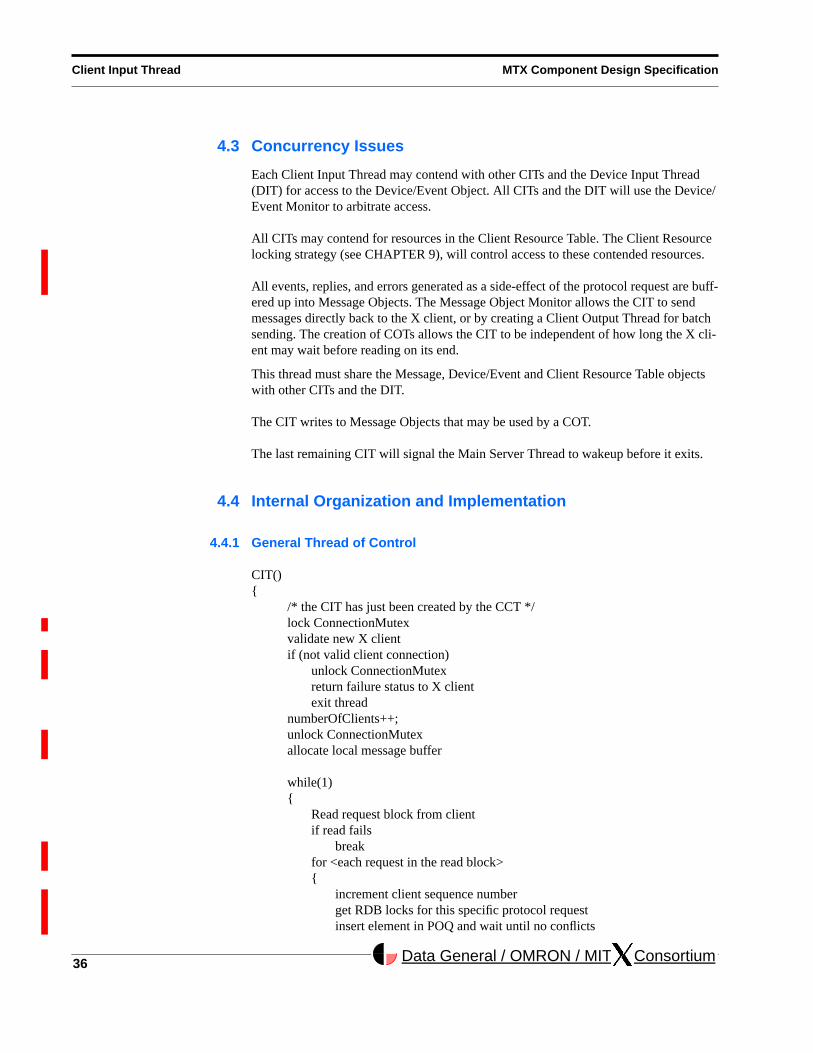
4.4.1 General Thread of Control
CIT(){
/* the CIT has just been created by the CCT */lock ConnectionMutexvalidate new X clientif (not valid client connection)
unlock ConnectionMutexreturn failure status to X clientexit thread
numberOfClients++;unlock ConnectionMutexallocate local message buffer
while(1){
Read request block from clientif read fails
breakfor <each request in the read block>{
increment client sequence numberget RDB locks for this specific protocol request insert element in POQ and wait until no conflicts
MTX Component Design Specification Client Input Thread
37Data General / OMRON / MIT . . ConsortiumData General / OMRON / MIT . . Consortium
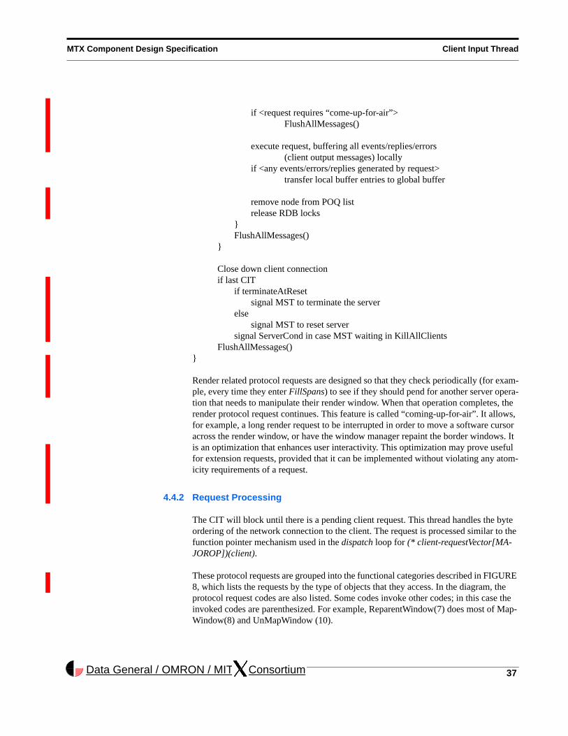
if <request requires “come-up-for-air”>FlushAllMessages()
execute request, buffering all events/replies/errors (client output messages) locally
if <any events/errors/replies generated by request>transfer local buffer entries to global buffer
remove node from POQ listrelease RDB locks
}FlushAllMessages()
}
Close down client connectionif last CIT
if terminateAtResetsignal MST to terminate the server
elsesignal MST to reset server
signal ServerCond in case MST waiting in KillAllClientsFlushAllMessages()
}
Render related protocol requests are designed so that they check periodically (for exam-ple, every time they enter FillSpans) to see if they should pend for another server opera-tion that needs to manipulate their render window. When that operation completes, the render protocol request continues. This feature is called “coming-up-for-air”. It allows, for example, a long render request to be interrupted in order to move a software cursor across the render window, or have the window manager repaint the border windows. It is an optimization that enhances user interactivity. This optimization may prove useful for extension requests, provided that it can be implemented without violating any atom-icity requirements of a request.
4.4.2 Request Processing
The CIT will block until there is a pending client request. This thread handles the byte ordering of the network connection to the client. The request is processed similar to the function pointer mechanism used in the dispatch loop for (* client-requestVector[MA-JOROP])(client).
These protocol requests are grouped into the functional categories described in FIGURE 8, which lists the requests by the type of objects that they access. In the diagram, the protocol request codes are also listed. Some codes invoke other codes; in this case the invoked codes are parenthesized. For example, ReparentWindow(7) does most of Map-Window(8) and UnMapWindow (10).

38
Client Input Thread MTX Component Design Specification
Data General / OMRON / MIT . . Consortium
All CITs will be able to process any protocol request including any pre-initialized exten-sions. Since each protocol request accesses both shared and private resources, locking policies will be invoked to protect multiple threads from corrupting shared resources.
For shared resources, the Client/Resource Locking strategy (see CHAPTER 9) is the arbitration policy. The CIT locks objects in the Client/Resource Database and inserts the protocol request on the Pending Operation Queue (POQ).
If a CIT wishes to gain access to event related objects (such as the event mask, Gra-bRec, or DeviceIntRec), the Client Input Thread will request access through the Device/Event Monitor (see CHAPTER 11). The Device/Event Monitor will insure exclusive access to the event related objects and block other requesting threads to enforce serial access to the event related objects.
As noted above, render protocol requests will have the ability to come-up-for-air.
All events that are generated as side effects of processing the protocol request will be processed by the Device/Event Monitor. Events, replies, and errors from a protocol request are then wrapped into messages via the Message Output Monitor. Errors and replies that originate in the Client Input Thread will be sent directly to the correspond-ing X Client. Events targeted for multiple clients will be buffered for batch processing by a Client Output Thread. In the MTX sample implementation, the COT is created dynamically within the Message Output Monitor (see CHAPTER 12) as the result of a flush, potentially initiated from a CIT. The MOM could be altered to allow the option of dynamic or static COTs, but only dynamic COTs are provided in the sample implemen-tation.
The CIT will also handle client shutdown activities. When a client dies or is killed, the appropriate CIT will free resources from the Client/Resource Table and cleanup local data structures. If the CIT represents the last client connected to the MTX server, then it will notify the Main Server Thread to wakeup and reset the server.
4.4.2.1 GrabServerA CIT cannot continue to process requests while another CIT has a pending GrabServer. The CIT will block on the POQ (see CHAPTER 10) until the grabbing CIT performs an UngrabServer request.
4.4.3 Client Output Delivery
Client Output, which includes events, errors, and replies, can be generated by the proto-col request back to the X client. All protocol requests can return errors. Some protocol requests can generate. events and replies. See [SG90] for a more detailed description.
The Device Input Thread can also generate events for an X client. In fact, multiple CITs and the DIT may generate events to the same X client at the same time. All events gen-erated by a single request in the CIT, or device input in the DIT, must be queued for delivery indivisibly with respect to events generated by other threads. See CHAPTER 12, the Message Output Monitor, for details about how the Client Output atomicity requirements are met.

MTX Component Design Specification Client Input Thread
39Data General / OMRON / MIT . . ConsortiumData General / OMRON / MIT . . Consortium
See CHAPTER 5 for a description of how the COT arranges for client output delivery.
4.4.3.1 Flushing Output to Clients Flushing of all client messages occurs at the following locations of the server:
• at the end of the CIT’s request block loop
• after the CIT has executed a client shutdown but before the thread exits
• after processing a device input event from DIT
• inside request loop of CIT but prior to arbitrarily long requests
4.4.4 Server Initialization and Control
The CCT creates the CIT during the client initialization phase. When the MST is told to reset, it will wait until the last CIT has exited before proceeding with the cleanup phase.
4.4.5 Client Initialization and Control
A CIT is created by the Client Connection Thread when an X Client wants to connect to the server. The CCT will validate the connection by running the EstablishNewConnec-tion functionality. After the new connection is established, the CIT is created.
The CIT will then run the InitialConnection and EstablishConnection functions. These requests are used to validate the connection and trade server information with the X Cli-ent. The new client sends a connection setup packet that contains the byte ordering for its host machine and authorization information.
Client specific authentication of the client connection is performed by the CIT as soon as it is created by the CCT. This frees the CCT to service other new client connections and should speed the process of starting up an X session.
After successfully validating the connection, the X client is considered to exist on the server side. The CIT then enters a continuous loop of reading protocol requests and operating on those requests. It only exits the loop when client termination is requested either voluntarily by the client, or involuntarily as a result of a server exception.
4.4.6 DDX Layer
If there is output to be sent to any devices, a CIT will manage that activity through the DDX layer. This includes writing to the graphics output device and generating feedback for the feedback devices (i.e. led and bell). Writing to the graphics output devices is a frequent operation and could generate an unacceptable number of thread context switches if this functionality were placed in a thread other than the Client Input Thread.
4.4.7 ScreenSaver
A CIT will control the screen saver through the GetScreenSaver, SetScreenSaver, and ForceScreenSaver protocol requests (see CHAPTER 15).

40
Client Input Thread MTX Component Design Specification
Data General / OMRON / MIT . . Consortium
4.4.8 XDM Interface
The initial connection by the display manager client to MTX will create a CIT dedicated to XDM. The XDM CIT is used to communicate XDMCP requests to the server.
4.4.9 FontServer Interface
The X server side of the Font Server (FS) will be adjusted so that only the CIT request-ing information from the Font Server will block on the FS connection. The X server will not need to receive Suspended status from the FS, nor will it need the work in progress queues to handle pending FS requests.
4.4.10 Extensions
Extensions should model the approach used by core requests to lock server objects.
4.4.11 R5 versus MTX
In the R5 server, the select fires when one of the file descriptors detects an X Client request. Each file descriptor is correlated with a connected client via the AllClients mask. The index into the mask is used to find the correct client record. The client record points to the input and output OS Comm records for the client. The protocol request is read from the input OS Comm record. The dispatch loop uses the major operation code of the request as an index into the request vector. This entry in the request vector is a pointer to the correct protocol function that will process the X Client’s request.
The MTX server localizes the processing of client requests to a CIT. Therefore, there is no need for all of the various client connection masks that are found in R5’s connec-tion.c file. The CIT does a blocking read on the client’s request socket; thus removing the dependence on the slow select call. Once the CIT detects a request, it does not have to use or manipulate any complicated masks to determine the client record or the client id. The CIT can immediately jump to validation of the request.
A CIT will have one input buffer and not manage a pool of buffers as currently exists in the R5 server. This approach allows the CIT to avoid extra locks in a performance criti-cal path of the server and trades-off the possibility of returning an input buffer to the system for clients that rarely issues requests.
FIGURE 10 shows that the top level of the Client Input Thread is a subset of the old dis-patch code.
FIGURE 11 through FIGURE 12 shows a logical division of the requests into protocol request categories with the create window request of the window category used as an example. This example continues in FIGURE 13 through FIGURE 14.
The create window example is typical of how each protocol request XXX is handled. The top layer of the ProcXXX module write locks the row of the Client Resource Table corresponding to the passed client. Generally, most of the processing is performed in the XXX module. The XXX module may access the Message Object and the Device/Event Object to send events or generate grabs. Access to the Device/Event Object is guarded

MTX Component Design Specification Client Input Thread
41Data General / OMRON / MIT . . ConsortiumData General / OMRON / MIT . . Consortium
by the DeviceEventMutex. Each batch of event related calls is preceded by a lock of DeviceEventMutex and then succeeded by the paired unlock of DeviceEventMutex.
FIGURE 10 CIT Top Level Structure Chart
ALLOCATE_LOCAL__
ProcessInputEvents
FlushIfCriticalOutputPending
size_MaxClients
WaitForSomething
nready
clientsReady
ReadRequestFromClient
client
result
CloseDownClient
client
_client_requestVector_
client
result
SendErrorToClient
MinorOpcodeOfRequest
clientMAJOROP
MinorOpcodeOfRequest errorValue
result
minoropcodeclient
FlushAllMessages
KillAllClients
DEALLOCATE_LOCAL__
clientReady
clientReady
Dispatch
ClientInputThread
ClientPtr

42
Client Input Thread MTX Component Design Specification
Data General / OMRON / MIT . . Consortium
FIGURE 11 CIT Proc Vector Logical Structure Chart
_ProcVector_
resultclient
_Proc_Windows_
_Proc_Atom_
_Proc_Property_
_Proc_Selection_
_Proc_Event_
_Proc_Pointer_
_Proc_Button_
_Proc_Keyboard_
_Proc_Server_
_Proc_Focus_
_Proc_Font_
_Proc_Pixmap_
_Proc_GC_
_Proc_GC_Area_
_Proc_GC_2D_
_Proc_Image_
_Proc_Text_
_Proc_Colormap_
_Proc_Cursor_
_Proc_Extension_
_Proc_ScrSaver_
_Proc_Access_Ctrl_
_Proc_Client_
_Proc_Misc_

MTX Component Design Specification Client Input Thread
43Data General / OMRON / MIT . . ConsortiumData General / OMRON / MIT . . Consortium
FIGURE 12 CIT Proc Windows Logical Structure Chart
_Proc_Windows_
resultclient
ProcCreateWindow
ProcChangeWindowAttributes
ProcGetWindowAttributes
ProcDestroyWindow
ProcDestroySubWindows
ProcChangeSaveSet
ProcReparentWindow
ProcMapWindow
ProcMapSubwindows
ProcUnmapWindow
ProcUnmapSubwindows
ProcConfigureWindow
ProcCirculateWindow
ProcGetGeometry
ProcQueryTree
ProcTranslateCoords

44
Client Input Thread MTX Component Design Specification
Data General / OMRON / MIT . . Consortium
FIGURE 13 CIT ProcCreateWindow Structure Chart
ProcCreateWindow
client result
REQUEST__
REQUEST_AT_LEAST_SIZE__
LEGAL_NEW_RESOURCE__
xCreateWindowReq
xCreateWindowReq
widclient
LookupWindow
clientrid
CreateWindowOnes
masklength
AddResource
BoolwidRT_WINDOW
stuff
pParent
result
pWin
client
pWin
test
LOCK_AND_VERIFY_WINDOW
UNLOCK_WINDOW_
client.CRT_Mclient.CRT_M

MTX Component Design Specification Client Input Thread
45Data General / OMRON / MIT . . ConsortiumData General / OMRON / MIT . . Consortium
FIGURE 14 CIT CreateWindow Structure Chart
CreateWindow
stuffpParent
result
pWin
client
FindWindowWithOptional
pParent pWindowOpt
AllocateWindow
pScreen pWin
SetWindowToDefaults
pWin
MakeWindowOptional
pWin
_RegionInit_
RealChildHead
xfree__
pWin
RegionRecNullBox
1
pParentpHead
SetWinSize SetBorderSize
pWin
pWin
_CreateWindow_
DeleteWindow
_PositionWindow_
RecalculateDeliverableEvents
ChangeWindowAttributes
EventSelectForWindow
WindowHasNewCursor
DeliverEvents
SubSend__
pWin
pWin
widpthread_mutex_lock
DeviceEventObject_M
pthread_mutex_unlock
EvnteObject_M

46
Client Input Thread MTX Component Design Specification
Data General / OMRON / MIT . . Consortium

MTX Component Design Specification Client Output Thread
47Data General / OMRON / MIT . . ConsortiumData General / OMRON / MIT . . Consortium
CHAPTER 5 Client Output Thread
5.1 Overview
Route messages from the server to the client.
The Client Output Thread (COT) thread (see FIGURE 15) is created within the Message Output Monitor (see CHAPTER 12) when a message flush occurs. The flush will have been initiated by a Client Input Thread or the Device Input Thread when these threads must send messages to X Clients.
A COTs sole purpose is to gather messages for a target client that have already been generated and queued, synchronize with other threads that may be trying to write to the same target client, and write the message data to the target clients socket.

48
Client Output Thread MTX Component Design Specification
Data General / OMRON / MIT . . Consortium
FIGURE 15 Client Output Thread
5.2 Data Objects
The Client Output Thread will use:
• the connection information for the client
• client specific data
• the global message buffer built by the producer thread
• message delivery locks, for synchronization
TransmitMessage
SyncDeliveryThreads
Global Message Buffer
Flush
ClientOutput
Connection Data
Message Delivery Locks
Client DataLocateMessagesTo Flush
FlushableMessages
LockedSocket

MTX Component Design Specification Client Output Thread
49Data General / OMRON / MIT . . ConsortiumData General / OMRON / MIT . . Consortium
5.3 Concurrency Issues
COTs are created only when needed and terminate after completing the delivery task. When the server communicates with clients via blocking I/O, it is required that the server avoid situations where a CIT or DIT might block because a certain client is not reading its messages. So, a COT was created for the sole purpose of delivering a set of messages to target client and then terminating. With this mechanism, a CIT or DIT will not block due to a client who has a full socket buffer.
There is one exception where COTs are not created for delivering messages. If a CIT is delivering messages directly back to the client to which it is associated, the CIT can deliver the messages. In this case, it is considered reasonable for a CIT to block if the client is not reading from its socket buffer. Note that round trip requests will always have a reply delivered from the CIT that generates it. This optimization saves a thread creation and context switch.
5.4 Internal Organization and Implementation
5.4.1 General Thread of Control
COT(){
look at implicit MessageDeliveryLock informationif <thread already waiting for same implicit lock>
thread exitobtain implicit MessageDeliveryLock
lock global message bufferlocate sublist of flushable messagesif <sublist is not empty>
remove sublist from list of all messages pending for clientunlock global message bufferbuild IOV array locallywritev to socketfree sublist
elseunlock global message buffer
release implicit MessageDeliveryLockthread exit
}
It is possible that more than one COT for the same client may exist at the same time. One of them will grab the implicit MessageDeliveryLock for the target client, one will wait for the currently executing COT to finish, while all others will realize that any cur-rent messages will eventually be flushed by the waiting thread and merely terminate without doing anything.

50
Client Output Thread MTX Component Design Specification
Data General / OMRON / MIT . . Consortium
Note that if a client is not reading from its socket, it is possible that a COT will block when it issues a writev(2). Messages destined for that client will begin to accumulate in the global message buffer. A mechanism is built into the Message Output Monitor that will try to detect this situation when memory cannot be allocated and will try to reclaim these messages (see CHAPTER 12).
The normal case for CIT generated events/replies/errors is that the CIT itself will be able to flush to the client and a COT will not have to be created.
Since most protocol requests will send directly to the socket, and DIT events happen rel-atively infrequently, creating COTs on the fly is a good idea because it will minimize thread management. We don’t want idle COTs sitting around taking up precious kernel structures. Also, with fewer COTs, the chance of a cache hit to find a COT is greater. It is believed that many threads based kernels can create threads very fast, perhaps even faster than it takes a thread to context switch into memory.
5.4.2 R5 versus MTX
In R5, client output delivery is handled by the protocol request or device input code at the moment it needs to deliver using WriteToClient(). In MTX, we decouple the delivery of messages for the CIT, and we will decouple the delivery of events for the DIT. So, the WriteToClient interface will be changed for producer threads to reflect the algorithm described in CHAPTER 4.
Since the COT uses many of the Message Object Monitor features, please see CHAP-TER 12 for more details on message delivery.

MTX Component Design Specification Device Input Thread
51Data General / OMRON / MIT . . ConsortiumData General / OMRON / MIT . . Consortium
CHAPTER 6 Device Input Thread
6.1 Overview
The Device Input Thread (DIT) waits for device input and routes device events to selected Client Output Threads.
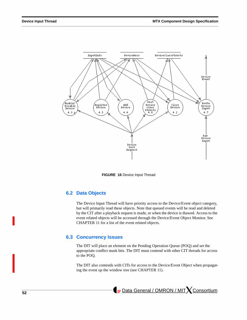
There will be one Device Input Thread to handle all device input to the server, although the ability to create multiple DITs will not be prohibited. In R5, device input from the mouse, keyboard, trackball, etc. currently executes in the ProcessInputEvents function. This function has device independent and device dependent code based on the type of device. The Device Input Thread (see FIGURE 16) will accept input from one or more registered devices. This thread will process the device input, format the correct device events, and deliver the device events through Client Output Threads.
52
Device Input Thread MTX Component Design Specification
Data General / OMRON / MIT . . Consortium
FIGURE 16 Device Input Thread
6.2 Data Objects
The Device Input Thread will have priority access to the Device/Event object category, but will primarily read these objects. Note that queued events will be read and deleted by the CIT after a playback request is made, or when the device is thawed. Access to the event related objects will be accessed through the Device/Event Object Monitor. See CHAPTER 11 for a list of the event related objects.
6.3 Concurrency Issues
The DIT will place an element on the Pending Operation Queue (POQ) and set the appropriate conflict mask bits. The DIT must contend with other CIT threads for access to the POQ.
The DIT also contends with CITs for access to the Device/Event Object when propagat-ing the event up the window tree (see CHAPTER 11).
MTX Component Design Specification Device Input Thread
53Data General / OMRON / MIT . . ConsortiumData General / OMRON / MIT . . Consortium
6.4 Internal Organization and Implementation
6.4.1 General Thread of Control
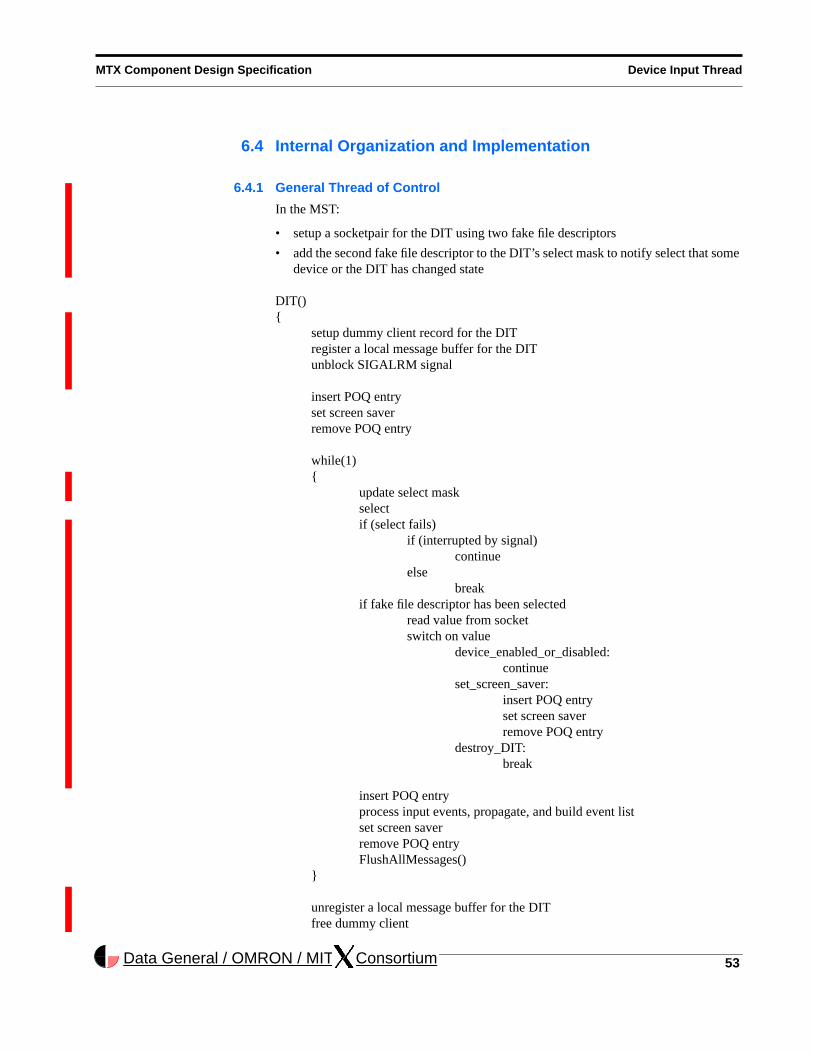
In the MST:
• setup a socketpair for the DIT using two fake file descriptors
• add the second fake file descriptor to the DIT’s select mask to notify select that some device or the DIT has changed state
DIT(){
setup dummy client record for the DITregister a local message buffer for the DITunblock SIGALRM signal
insert POQ entryset screen saverremove POQ entry
while(1){
update select maskselectif (select fails)
if (interrupted by signal)continue
elsebreak
if fake file descriptor has been selectedread value from socketswitch on value
device_enabled_or_disabled:continue
set_screen_saver:insert POQ entryset screen saverremove POQ entry
destroy_DIT:break
insert POQ entryprocess input events, propagate, and build event listset screen saverremove POQ entryFlushAllMessages()
}
unregister a local message buffer for the DITfree dummy client
54
Device Input Thread MTX Component Design Specification
Data General / OMRON / MIT . . Consortium
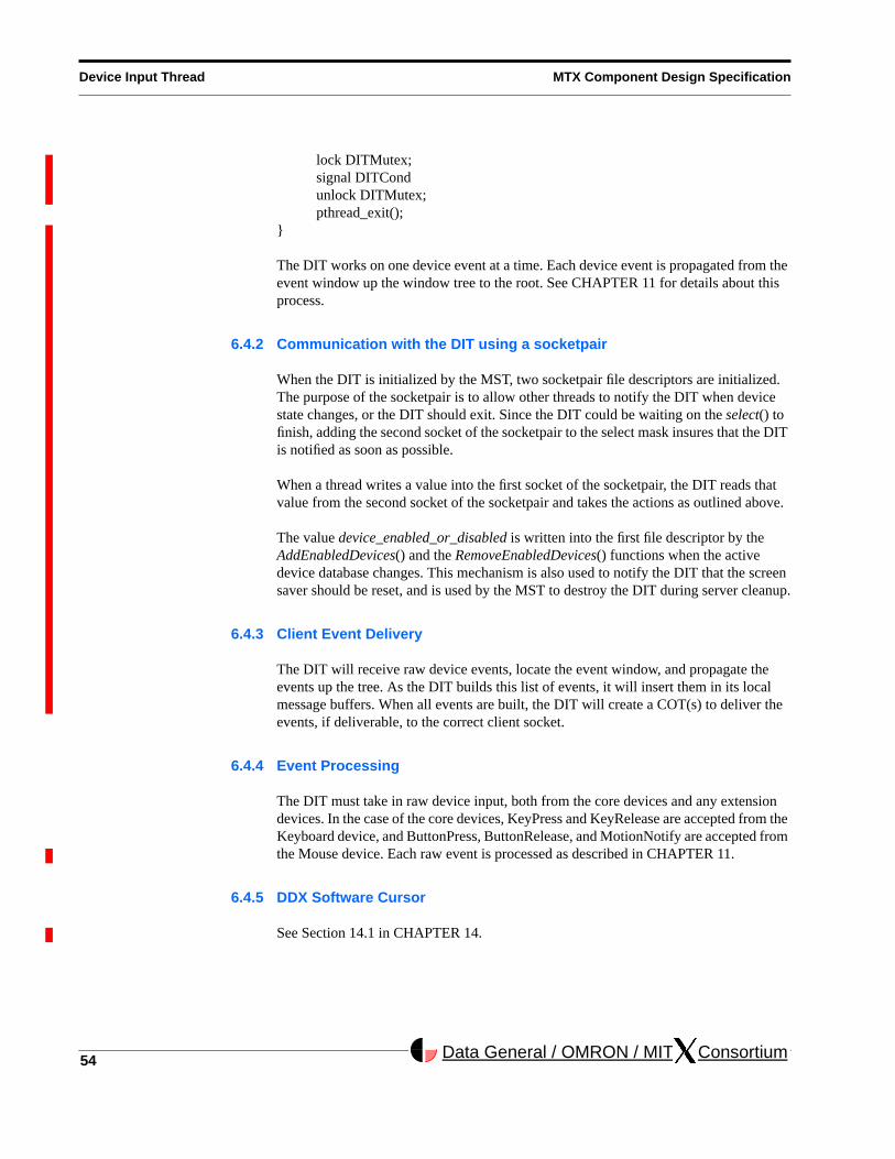
lock DITMutex;signal DITCondunlock DITMutex;pthread_exit();
}
The DIT works on one device event at a time. Each device event is propagated from the event window up the window tree to the root. See CHAPTER 11 for details about this process.
6.4.2 Communication with the DIT using a socketpair
When the DIT is initialized by the MST, two socketpair file descriptors are initialized. The purpose of the socketpair is to allow other threads to notify the DIT when device state changes, or the DIT should exit. Since the DIT could be waiting on the select() to finish, adding the second socket of the socketpair to the select mask insures that the DIT is notified as soon as possible.
When a thread writes a value into the first socket of the socketpair, the DIT reads that value from the second socket of the socketpair and takes the actions as outlined above.
The value device_enabled_or_disabled is written into the first file descriptor by the AddEnabledDevices() and the RemoveEnabledDevices() functions when the active device database changes. This mechanism is also used to notify the DIT that the screen saver should be reset, and is used by the MST to destroy the DIT during server cleanup.
6.4.3 Client Event Delivery
The DIT will receive raw device events, locate the event window, and propagate the events up the tree. As the DIT builds this list of events, it will insert them in its local message buffers. When all events are built, the DIT will create a COT(s) to deliver the events, if deliverable, to the correct client socket.
6.4.4 Event Processing
The DIT must take in raw device input, both from the core devices and any extension devices. In the case of the core devices, KeyPress and KeyRelease are accepted from the Keyboard device, and ButtonPress, ButtonRelease, and MotionNotify are accepted from the Mouse device. Each raw event is processed as described in CHAPTER 11.
6.4.5 DDX Software Cursor
See Section 14.1 in CHAPTER 14.

MTX Component Design Specification Device Input Thread
55Data General / OMRON / MIT . . ConsortiumData General / OMRON / MIT . . Consortium
6.4.6 ScreenSaver
If ScreenSaver is OFF and the DIT detects that no input has been received during the ScreenSaverInterval, the DIT will set ScreenSaver ON.
If ScreenSaver is set ON and device input is received, the DIT sets ScreenSaver OFF.
See CHAPTER 15.
6.4.7 R5 versus MTX
The MTX implementation of the DIT selects on those devices that were initialized and started by the Main Server Thread when the Device Input Thread was created. The select is similar to that found in the WaitForSomething module of the R5 implementa-tion.
Another implementation dependency is in the call to process the device input. For instance, on the Omron Luna88k, when a device has input for the selected DIT, the DIT calls ProcessInputEvents. These are similar to the calls seen in R5.
The DIT must do blocking I/O, suggested in the structure chart by the select. When the thread wakes up it will call ProcessInputEvents. The only other changes necessary are pthread locks/unlocks of the DeviceEventMutex before calling any DIX event-related functions (e.g. *processInputProc(), AddInput(), etc.).

56
Device Input Thread MTX Component Design Specification
Data General / OMRON / MIT . . Consortium
FIGURE 17 DIT deviceProc example Structure Chart
_deviceProc_
deviceProcExample
DeviceInputThread
pthread_create
select ProcessDeviceEvent
MTX Component Design Specification Signal Handling Thread
57Data General / OMRON / MIT . . ConsortiumData General / OMRON / MIT . . Consortium
CHAPTER 7 Signal Handling Thread
7.1 Overview
The Signal Handling Thread (SHT) is responsible for detecting and taking action on all process-wide signals that are handled by the MTX server. Assuring that all server pro-cessed signals are delivered to the SHT will relieve all other threads from the responsi-bility of providing for potential interrupts during certain system calls.
7.2 Data Objects
A signal set consisting of all signals to be processed by the MTX server is initialized at server start-up time and then accessed but never modified. The only data modified by the SHT is the global flag, serverException, which indicates whether the server should be terminated or recycled.
7.3 Concurrency Issues
The SHT is created by the MST during initial start-up and remains active until the server terminates.
The set of all signals to be processed by the server must be initialized and blocked by the MST prior to any other thread being created. When new threads are eventually cre-

58
Signal Handling Thread MTX Component Design Specification
Data General / OMRON / MIT . . Consortium
ated, they will inherit the set of blocked signals as created by the MST. The SHT will specifically ask for delivery of blocked signals, thus assuring all server processed sig-nals are delivered only to the SHT.
7.4 Internal Organization and Implementation
7.4.1 Processed Signals
The MTX server will catch the following signals and take the associated action.
• SIGHUP: Signal the MST to recycle the server.
• SIGINT: Signal the MST to terminate the server.
• SIGTERM: Signal the MST to terminate the server.
• SIGALRM: Signal the DIT to enable screen saver.
• SIGPIPE: Catches and ignores signal.
7.4.2 SHT Algorithm
The MST is the only thread that modifies its signal state and does this prior to creating any new threads. Threads inherit the signal state of their creator, thus, all threads will have identical signal states since the MST is at the root of the thread hierarchy (note cur-rent exception to this in Section 7.4.3). Prior to creating any threads, the MST will block all signals that are to be processed by the MTX server. A signal that is blocked by all threads will pend until the signal state of the threads changes (never for MTX) or a thread requests delivery of a pending signal via the sigwait() system call. The following is the SHT algorithm.
SHT(){
for (;;)switch (sigwait(<mtx signal mask>){
case SIGINT:case SIGTERM:
signal MST to terminate serverbreak
case SIGHUP:signal MST to reset serverbreak
case SIGALRM:enable screen saverbreak
case SIGPIPE:default:
break}
}

MTX Component Design Specification Signal Handling Thread
59Data General / OMRON / MIT . . ConsortiumData General / OMRON / MIT . . Consortium
7.4.3 SIGALRM Delivery
SIGALRM is special cased in the implementation as of this writing. It is unclear in Draft 6 of P1003.4a as to whether SIGALRM is delivered like other signals on a pro-cess-wide basis, or if it is delivered only to the thread that initiates the alarm. The cur-rent implementation allows for SIGALRM to be delivered only to the thread that initiates the alarm. Only the DIT will initiate an alarm and thus must be capable of receiving a SIGALRM. If a future Draft of P1003.4a defines SIGALRM delivery to be process-wide, the implementation could be cleaned up by assuming all signals are han-dled via the SHT.

60
Signal Handling Thread MTX Component Design Specification
Data General / OMRON / MIT . . Consortium