composite design and manufacturing - maya htt composites engineering - desig… · composite design...
TRANSCRIPT

Smarter decisions, better products. Smarter decisions, better products. Smarter decisions, better products.
Composite Design and Manufacturing Solutions for Innovative Composites Engineering, September 25, 2014
Unrestricted / © Siemens AG 2013. All Rights Reserved.
Page 2 Siemens PLM Software Page 2 Siemens PLM Software 2013-07-15 Page 2 Siemens PLM Software
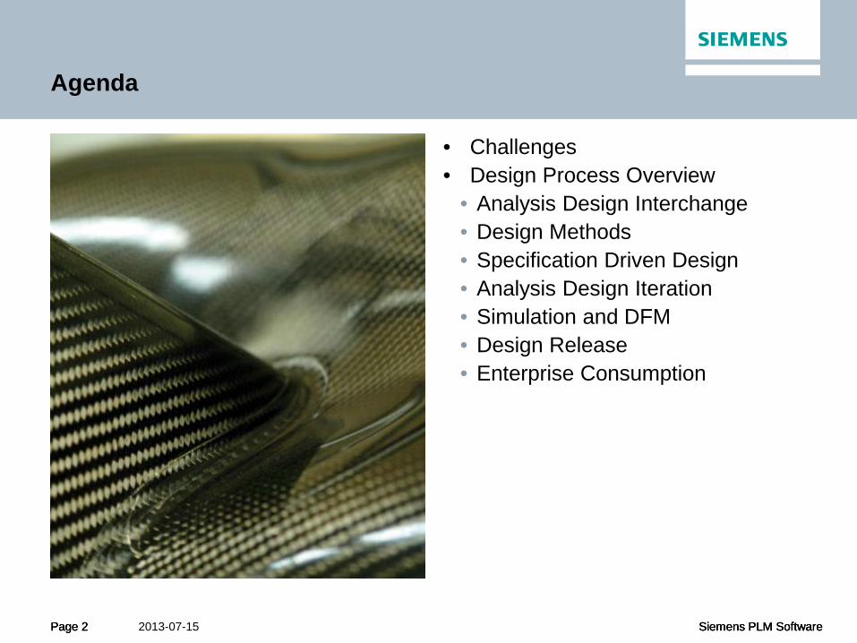
Agenda
• Challenges • Design Process Overview
• Analysis Design Interchange • Design Methods • Specification Driven Design • Analysis Design Iteration • Simulation and DFM • Design Release • Enterprise Consumption

Page 3 Siemens PLM Software Page 3 Siemens PLM Software 2013-07-15 Page 3 Siemens PLM Software
Challenges | Solutions
Solutions:
1. Concurrent engineering approach
2. Tools that support communication
3. Design for manufacturing
Cha
lleng
es
Challenges:
1. Achieving optimal composite products
2. Reducing time for development
3. Increasing production rate and quality

Page 4 Siemens PLM Software Page 4 Siemens PLM Software 2013-07-15 Page 4 Siemens PLM Software
"Overdesign to address uncertainty negates the advantages of composites. This leads to excess weight, schedule, and cost"
"Overdesigned composites cannot compete with lower-cost, established material systems – but composites are the future."
Industry Observations …
OVE
RD
ESIG
N
Overdesign

Page 5 Siemens PLM Software Page 5 Siemens PLM Software 2013-07-15 Page 5 Siemens PLM Software
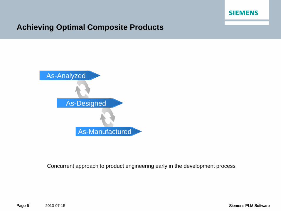
Achieving Optimal Composite Products
Manufacturing Design Analysis
Concurrent approach to product engineering early in the development process
Page 6 Siemens PLM Software Page 6 Siemens PLM Software 2013-07-15 Page 6 Siemens PLM Software
Achieving Optimal Composite Products
Analysis As-Analyzed
As-Designed
As-Manufactured
Concurrent approach to product engineering early in the development process

Page 7 Siemens PLM Software Page 7 Siemens PLM Software 2013-07-15 Page 7 Siemens PLM Software
Achieving Optimal Composite Products
Analysis As-Analyzed
As-Designed
As-Manufactured
Concurrent approach to product engineering early in the development process
Page 8 Siemens PLM Software Page 8 Siemens PLM Software 2013-07-15 Page 8 Siemens PLM Software
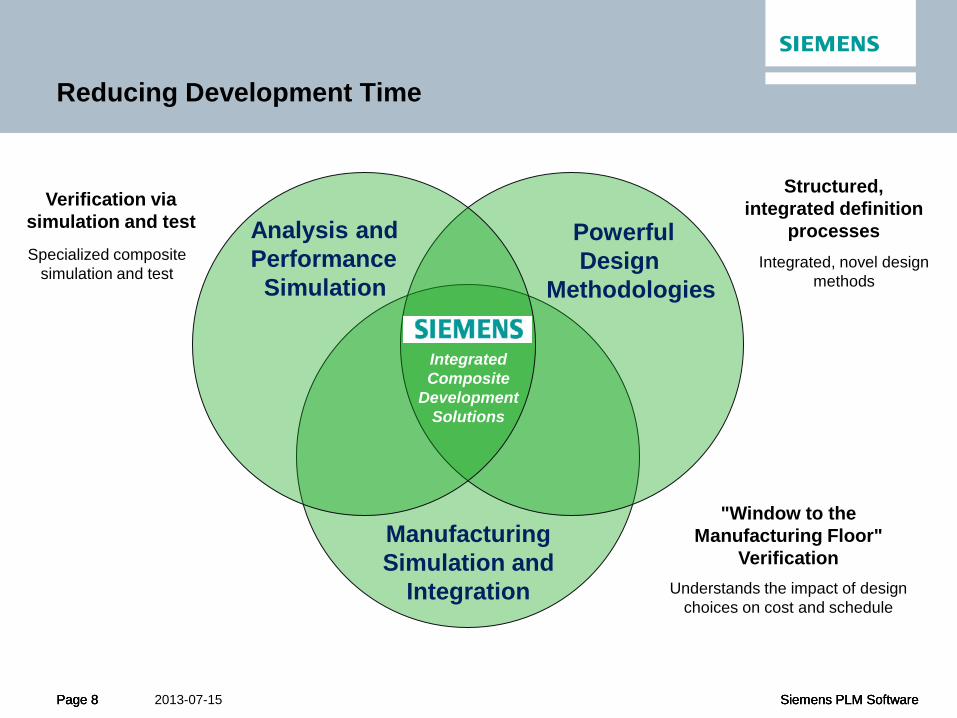
Reducing Development Time
Analysis and Performance Simulation
Powerful Design Methodologies
Manufacturing Simulation and
Integration
Integrated Composite
Development Solutions
Structured, integrated definition
processes
Verification via simulation and test
Specialized composite simulation and test
Integrated, novel design methods
"Window to the Manufacturing Floor"
Verification Understands the impact of design
choices on cost and schedule

Page 9 Siemens PLM Software Page 9 Siemens PLM Software 2013-07-15 Page 9 Siemens PLM Software
Consolidate parts to minimize assembly procedures
Reduce the material used to make the part
More quickly bring the part into optimized, volume production
All require iterative, cross-disciplinary optimization to
achieve real savings
Methods to increase production rate and quality
Increasing Production Rate and Quality

Page 10 Siemens PLM Software Page 10 Siemens PLM Software 2013-07-15 Page 10 Siemens PLM Software
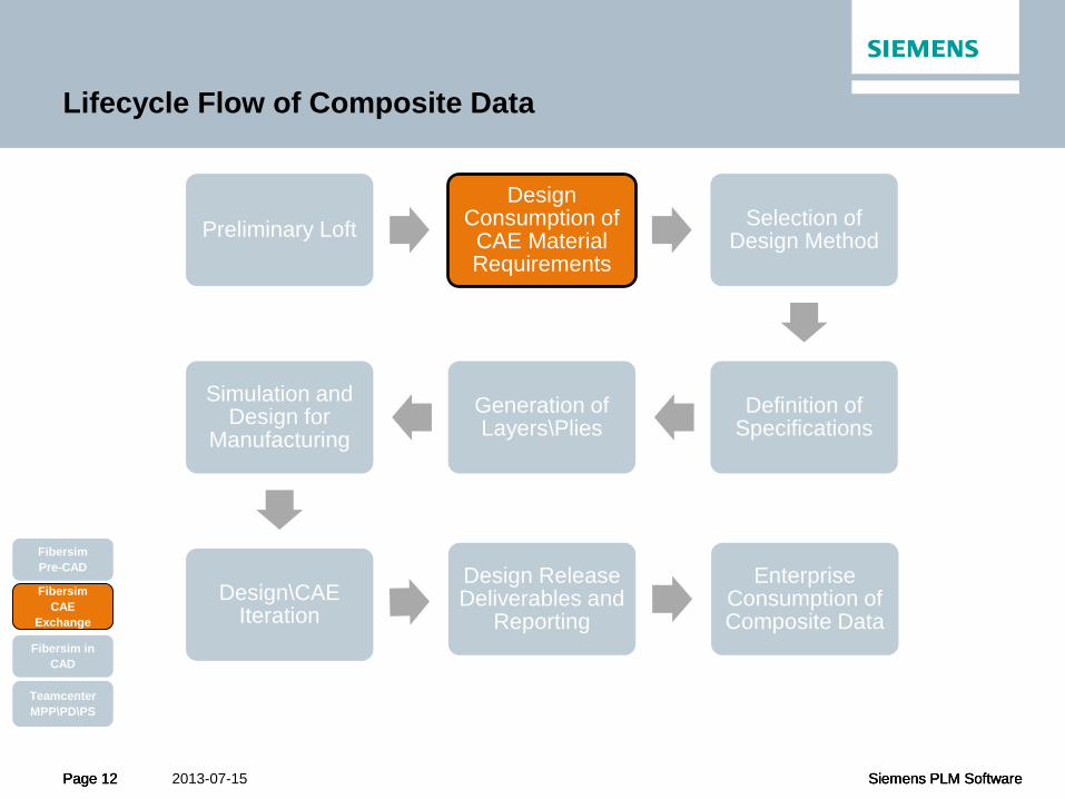
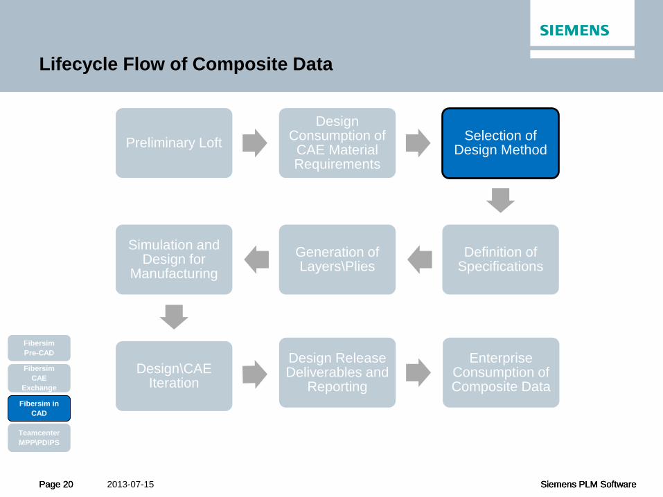
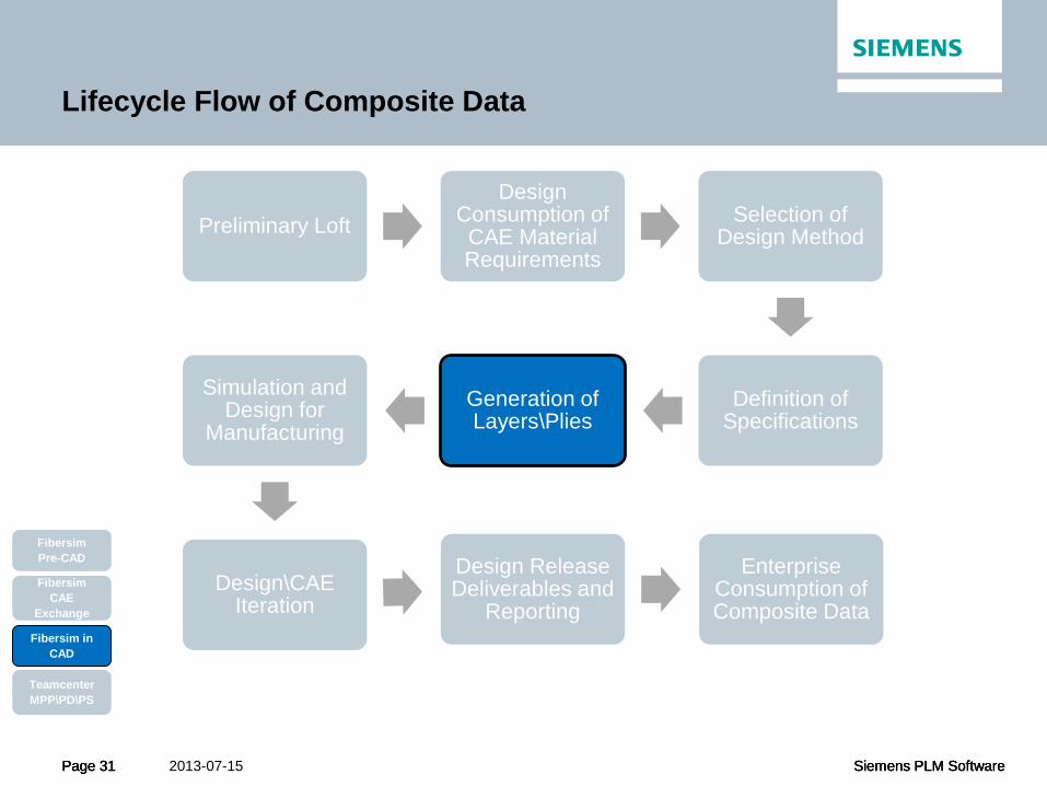
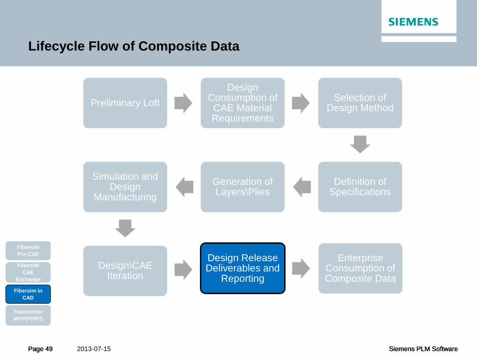
Lifecycle Flow of Composite Data
Preliminary Loft Design
Consumption of CAE Material Requirements
Selection of Design Method
Definition of Specifications
Generation of Layers\Plies
Simulation and Design for
Manufacturing
Design\CAE Iteration
Design Release Deliverables and
Reporting
Enterprise Consumption of Composite Data
Fibersim Pre-CAD
Fibersim in CAD
Teamcenter MPP\PD\PS
Fibersim CAE
Exchange
Page 11 Siemens PLM Software Page 11 Siemens PLM Software 2013-07-15 Page 11 Siemens PLM Software
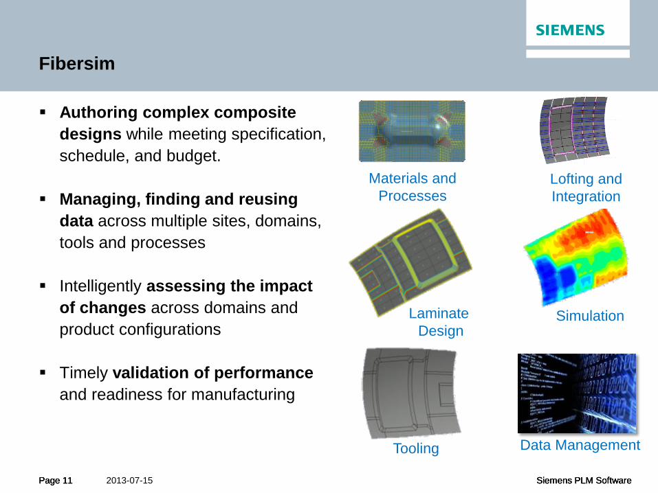
Materials and Processes
Fibersim
Authoring complex composite designs while meeting specification, schedule, and budget.
Managing, finding and reusing data across multiple sites, domains, tools and processes
Intelligently assessing the impact of changes across domains and product configurations
Timely validation of performance and readiness for manufacturing
Laminate Design
Lofting and Integration
Simulation
Tooling Data Management
Page 12 Siemens PLM Software Page 12 Siemens PLM Software 2013-07-15 Page 12 Siemens PLM Software
Lifecycle Flow of Composite Data
Preliminary Loft Design
Consumption of CAE Material Requirements
Selection of Design Method
Definition of Specifications
Generation of Layers\Plies
Simulation and Design for
Manufacturing
Design\CAE Iteration
Design Release Deliverables and
Reporting
Enterprise Consumption of Composite Data
Fibersim Pre-CAD
Fibersim in CAD
Teamcenter MPP\PD\PS
Fibersim CAE
Exchange
Page 13 Siemens PLM Software Page 13 Siemens PLM Software 2013-07-15 Page 13 Siemens PLM Software
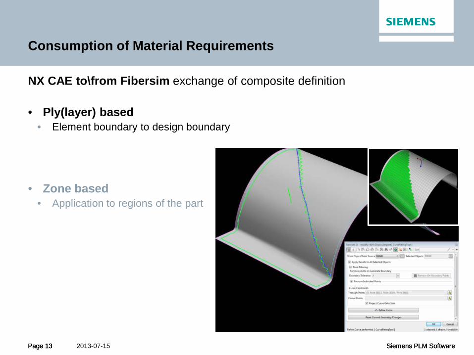
Consumption of Material Requirements
NX CAE to\from Fibersim exchange of composite definition • Ply(layer) based
• Element boundary to design boundary
• Zone based • Application to regions of the part
Page 14 Siemens PLM Software Page 14 Siemens PLM Software 2013-07-15 Page 14 Siemens PLM Software
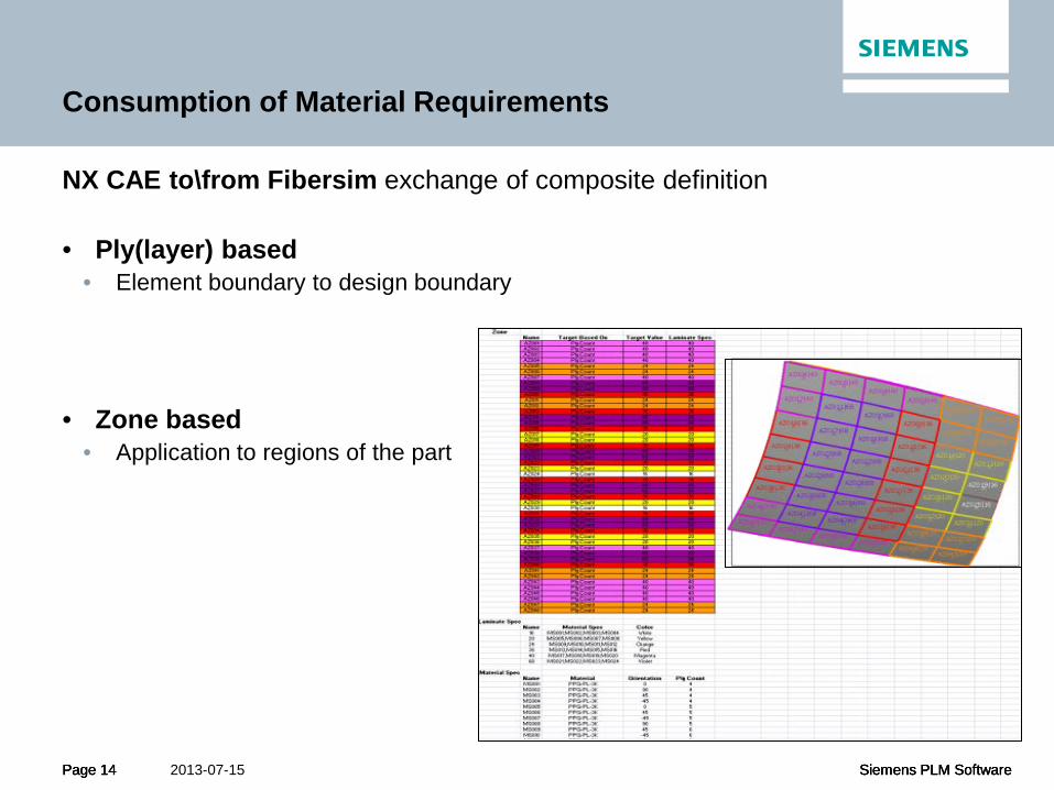
Consumption of Material Requirements
NX CAE to\from Fibersim exchange of composite definition • Ply(layer) based
• Element boundary to design boundary
• Zone based • Application to regions of the part

Page 15 Siemens PLM Software Page 15 Siemens PLM Software 2013-07-15 Page 15 Siemens PLM Software
Preliminary Simulation Model
• Split the mold surface following zones, with boundaries that: • Are physically meaningful • Are arbitrarily defined for downstream optimization
• Mesh the resulting faces • Define laminates
• Import from Excel • NX Open

Page 16 Siemens PLM Software Page 16 Siemens PLM Software 2013-07-15 Page 16 Siemens PLM Software
Preliminary Simulation Model

Page 17 Siemens PLM Software Page 17 Siemens PLM Software 2013-07-15 Page 17 Siemens PLM Software
Design Variable Creation

Page 18 Siemens PLM Software Page 18 Siemens PLM Software 2013-07-15 Page 18 Siemens PLM Software
Nastran Design Optimization
Page 19 Siemens PLM Software Page 19 Siemens PLM Software 2013-07-15 Page 19 Siemens PLM Software
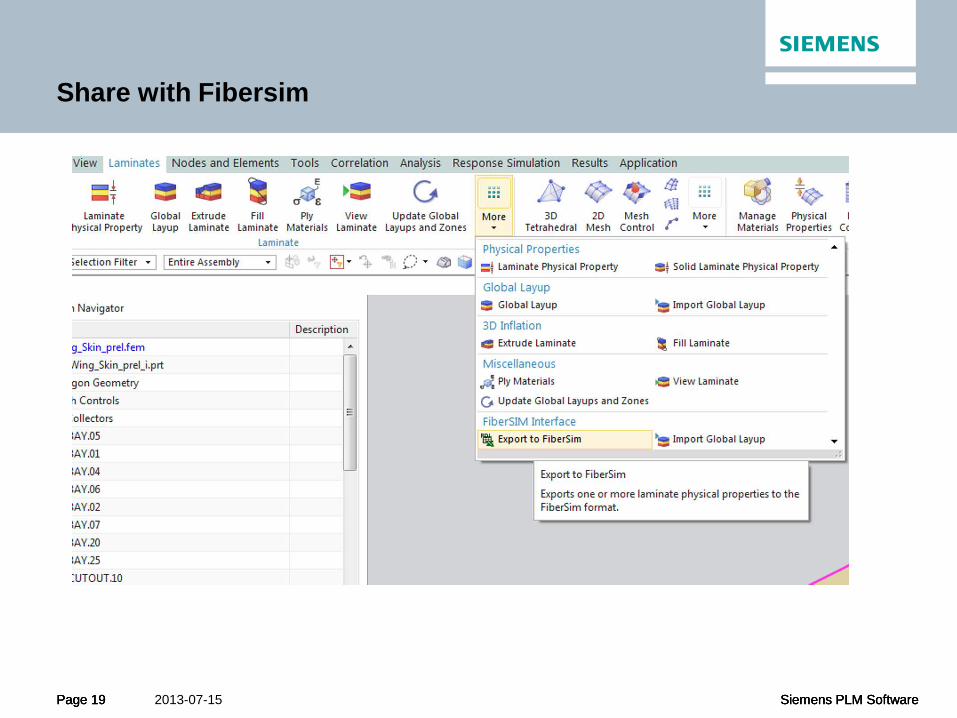
Share with Fibersim
Page 20 Siemens PLM Software Page 20 Siemens PLM Software 2013-07-15 Page 20 Siemens PLM Software
Lifecycle Flow of Composite Data
Preliminary Loft Design
Consumption of CAE Material Requirements
Selection of Design Method
Definition of Specifications
Generation of Layers\Plies
Simulation and Design for
Manufacturing
Design\CAE Iteration
Design Release Deliverables and
Reporting
Enterprise Consumption of Composite Data
Fibersim Pre-CAD
Fibersim in CAD
Teamcenter MPP\PD\PS
Fibersim CAE
Exchange

Page 21 Siemens PLM Software Page 21 Siemens PLM Software 2013-07-15 Page 21 Siemens PLM Software
Fibersim Powerful Design
Flexible design method for hand layup
Captures all data and assures manufacturability
Ply Based Zone Based
Structure Based Multi Ply Based
Allows effective optimization of complex designs
Supports robust analysis workflows
Automates ply based design
Best of ply and zone
Allows late design modifications without adding tedious work
Driven from mating specs
Automates design for wings/fuselages
Enables automated material deposition

Page 22 Siemens PLM Software Page 22 Siemens PLM Software 2013-07-15 Page 22 Siemens PLM Software
Fibersim Powerful Design
Flexible design method for hand layup
Captures all data and assures manufacturability
Ply Based Zone Based
Structure Based Multi Ply Based
Allows effective optimization of complex designs
Supports robust analysis workflows
Automates ply based design
Best of ply and zone
Allows late design modifications without adding tedious work
Driven from mating specs
Automates design for wings/fuselages
Enables automated material deposition
New

Page 23 Siemens PLM Software Page 23 Siemens PLM Software 2013-07-15 Page 23 Siemens PLM Software
Lifecycle Flow of Composite Data
Preliminary Loft Design
Consumption of CAE Material Requirements
Selection of Design Method
Definition of Specifications
Generation of Layers\Plies
Simulation and Design for
Manufacturing
Design\CAE Iteration
Design Release Deliverables and
Reporting
Enterprise Consumption of Composite Data
Fibersim Pre-CAD
Fibersim in CAD
Teamcenter MPP\PD\PS
Fibersim CAE
Exchange
Page 24 Siemens PLM Software Page 24 Siemens PLM Software 2013-07-15 Page 24 Siemens PLM Software
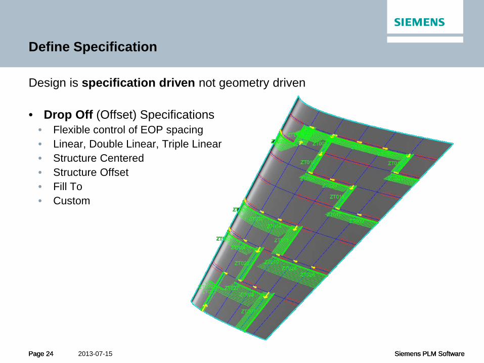
Define Specification
Design is specification driven not geometry driven • Drop Off (Offset) Specifications
• Flexible control of EOP spacing • Linear, Double Linear, Triple Linear • Structure Centered • Structure Offset • Fill To • Custom

Page 25 Siemens PLM Software Page 25 Siemens PLM Software 2013-07-15 Page 25 Siemens PLM Software
Define Specification
Design is specification driven not geometry driven • Drop Off (Offset) Specifications
• Flexible control of EOP spacing • Linear, Double Linear, Triple Linear • Structure Centered • Structure Offset • Fill To • Custom

Page 26 Siemens PLM Software Page 26 Siemens PLM Software 2013-07-15 Page 26 Siemens PLM Software
Define Specification
Design is specification driven not geometry driven • Drop Off (Offset) Specifications
• Flexible control of EOP spacing • Linear, Double Linear, Triple Linear • Structure Centered • Structure Offset • Fill To • Custom
Page 27 Siemens PLM Software Page 27 Siemens PLM Software 2013-07-15 Page 27 Siemens PLM Software
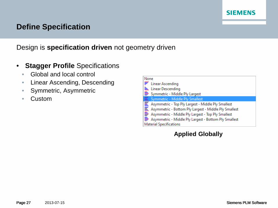
Define Specification
Design is specification driven not geometry driven • Stagger Profile Specifications
• Global and local control • Linear Ascending, Descending • Symmetric, Asymmetric • Custom
Applied Globally
Page 28 Siemens PLM Software Page 28 Siemens PLM Software 2013-07-15 Page 28 Siemens PLM Software
Define Specification
Design is specification driven not geometry driven • Stagger Profile Specifications
• Global and local control • Linear Ascending, Descending • Symmetric, Asymmetric • Custom
Applied Locally

Page 29 Siemens PLM Software Page 29 Siemens PLM Software 2013-07-15 Page 29 Siemens PLM Software
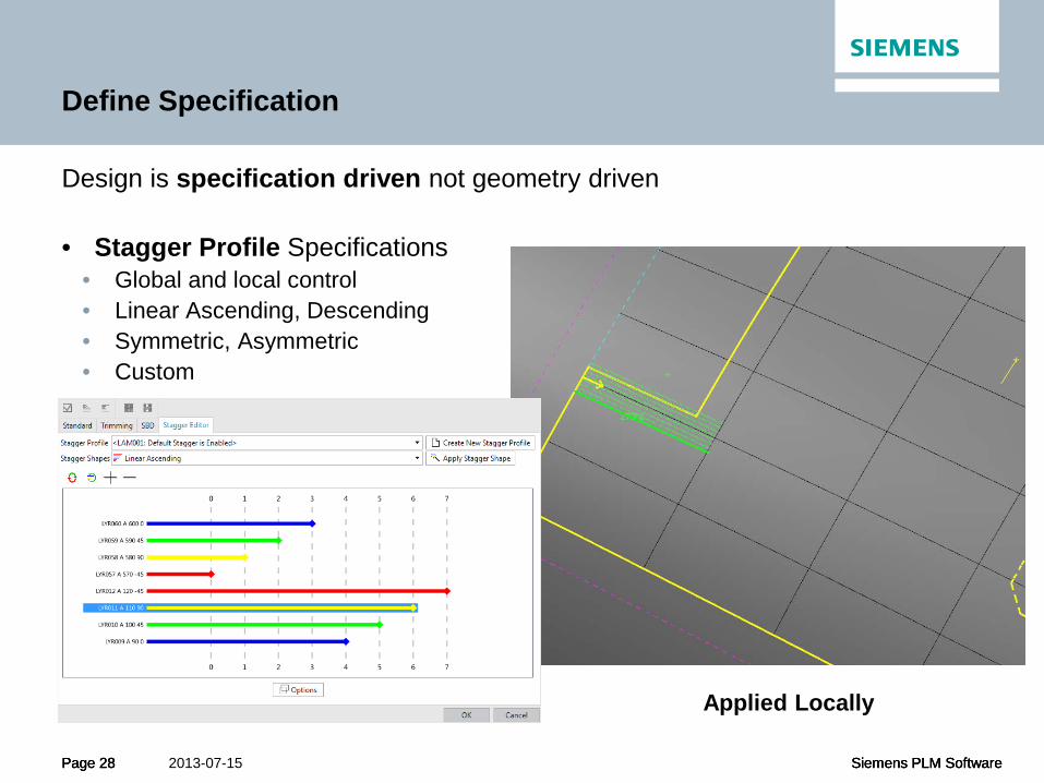
Define Specification
Design is specification driven not geometry driven • Stagger Profile Specifications
• Global and local control • Linear Ascending, Descending • Symmetric, Asymmetric • Custom
Applied Globally
Applied Locally

Page 30 Siemens PLM Software Page 30 Siemens PLM Software 2013-07-15 Page 30 Siemens PLM Software
Define Specification
Design is specification driven not geometry driven • Corner Behavior
• Variable, Constant, Min Length, Fixed Chamfer • Minimum Course
Page 31 Siemens PLM Software Page 31 Siemens PLM Software 2013-07-15 Page 31 Siemens PLM Software
Lifecycle Flow of Composite Data
Preliminary Loft Design
Consumption of CAE Material Requirements
Selection of Design Method
Definition of Specifications
Generation of Layers\Plies
Simulation and Design for
Manufacturing
Design\CAE Iteration
Design Release Deliverables and
Reporting
Enterprise Consumption of Composite Data
Fibersim Pre-CAD
Fibersim in CAD
Teamcenter MPP\PD\PS
Fibersim CAE
Exchange

Page 32 Siemens PLM Software Page 32 Siemens PLM Software 2013-07-15 Page 32 Siemens PLM Software
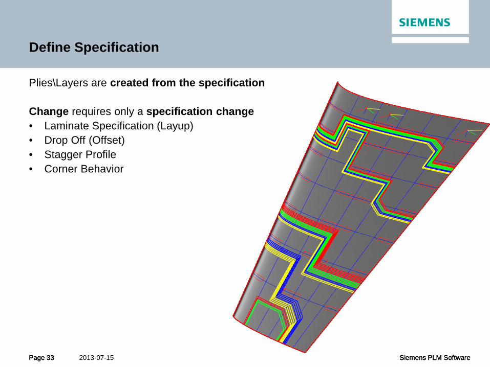
Define Specification
Plies\Layers are created from the specification Change requires only a specification change • Laminate Specification (Layup) • Drop Off (Offset) • Stagger Profile • Corner Behavior
Page 33 Siemens PLM Software Page 33 Siemens PLM Software 2013-07-15 Page 33 Siemens PLM Software
Define Specification
Plies\Layers are created from the specification Change requires only a specification change • Laminate Specification (Layup) • Drop Off (Offset) • Stagger Profile • Corner Behavior

Page 34 Siemens PLM Software Page 34 Siemens PLM Software 2013-07-15 Page 34 Siemens PLM Software
Define Specification
Plies\Layers are created from the specification Change requires only a specification change • Laminate Specification (Layup) • Drop Off (Offset) • Stagger Profile • Corner Behavior

Page 35 Siemens PLM Software Page 35 Siemens PLM Software 2013-07-15 Page 35 Siemens PLM Software
Lifecycle Flow of Composite Data
Preliminary Loft Design
Consumption of CAE Material Requirements
Selection of Design Method
Definition of Specifications
Generation of Layers\Plies
Simulation and Design for
Manufacturing
Design\CAE Iteration
Design Release Deliverables and
Reporting
Enterprise Consumption of Composite Data
Fibersim Pre-CAD
Fibersim in CAD
Teamcenter MPP\PD\PS
Fibersim CAE
Exchange
Page 36 Siemens PLM Software Page 36 Siemens PLM Software 2013-07-15 Page 36 Siemens PLM Software
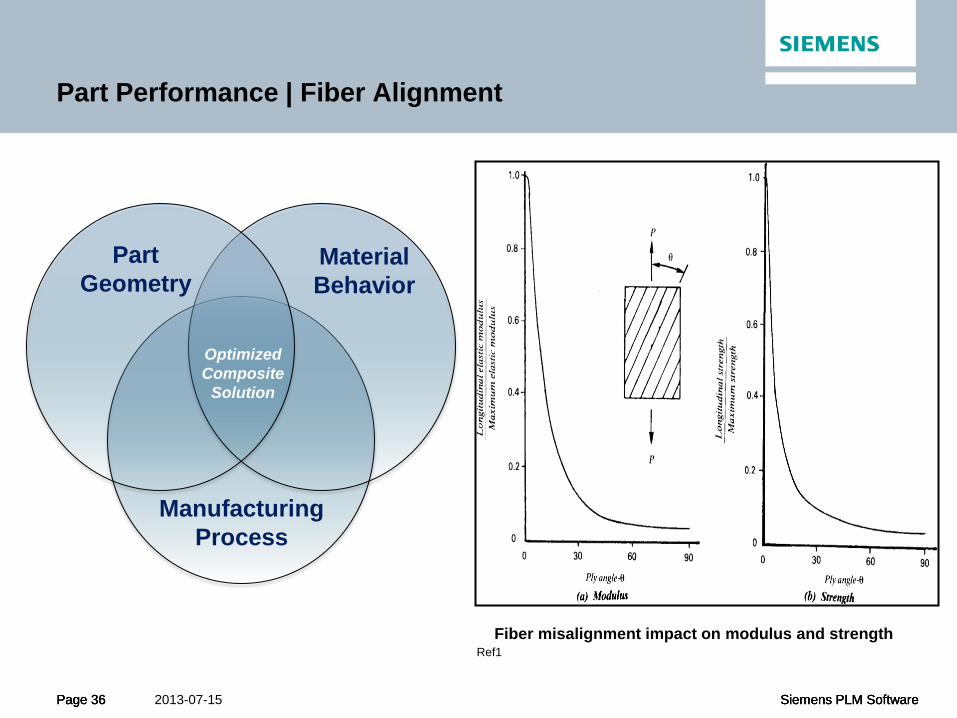
Part Performance | Fiber Alignment
Fiber misalignment impact on modulus and strength Ref1
Part Geometry
Material Behavior
Manufacturing Process
Optimized Composite
Solution
Page 37 Siemens PLM Software Page 37 Siemens PLM Software 2013-07-15 Page 37 Siemens PLM Software
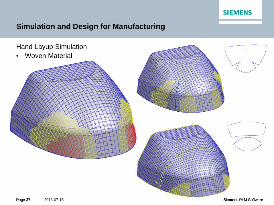
Simulation and Design for Manufacturing
Hand Layup Simulation • Woven Material

Page 38 Siemens PLM Software Page 38 Siemens PLM Software 2013-07-15 Page 38 Siemens PLM Software
Simulation and Design for Manufacturing
Hand Layup Simulation
start layup here
start layup here
start layup here
start layup here
Process Effects Material Effects

Page 39 Siemens PLM Software Page 39 Siemens PLM Software 2013-07-15 Page 39 Siemens PLM Software
Simulation and Design for Manufacturing
• Fiber steering • Localized deformation • Fiber buckling
Unique to
Fibersim

Page 40 Siemens PLM Software Page 40 Siemens PLM Software 2013-07-15 Page 40 Siemens PLM Software
Simulation and Design for Manufacturing
AFP/ATL • Uni Tape Tow • Machine Limitations
• Min Course • Across Cut Angle • Min Cut Width
Understanding Machine Characteristics Effects on Design

Page 41 Siemens PLM Software Page 41 Siemens PLM Software 2013-07-15 Page 41 Siemens PLM Software
Simulation and Design for Manufacturing
ATL/AFP • Import of path planning • Design changes • Achieving fiber orientations
Path Planning in the Context of Design
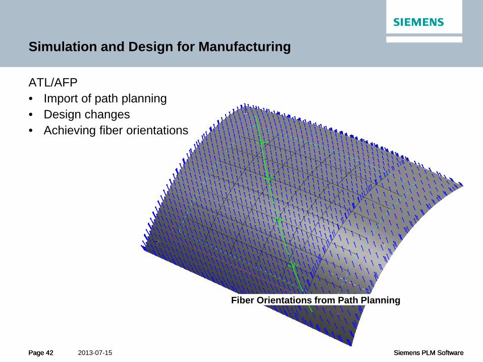
Page 42 Siemens PLM Software Page 42 Siemens PLM Software 2013-07-15 Page 42 Siemens PLM Software
Simulation and Design for Manufacturing
ATL/AFP • Import of path planning • Design changes • Achieving fiber orientations
Fiber Orientations from Path Planning

Page 43 Siemens PLM Software Page 43 Siemens PLM Software 2013-07-15 Page 43 Siemens PLM Software
Simulation and Design for Manufacturing
ATL/AFP • Import of path planning • Design changes • Achieving fiber orientations
Fiber Orientations from Path Planning Variation from Desired (Yellow-5Deg, Red-10Deg)

Page 44 Siemens PLM Software Page 44 Siemens PLM Software 2013-07-15 Page 44 Siemens PLM Software
Lifecycle Flow of Composite Data
Preliminary Loft Design
Consumption of CAE Material Requirements
Selection of Design Method
Definition of Specifications
Generation of Layers\Plies
Simulation and Design for
Manufacturing
Design\CAE Iteration
Design Release Deliverables and
Reporting
Enterprise Consumption of Composite Data
Fibersim Pre-CAD
Fibersim in CAD
Teamcenter MPP\PD\PS
Fibersim CAE
Exchange
Page 45 Siemens PLM Software Page 45 Siemens PLM Software 2013-07-15 Page 45 Siemens PLM Software
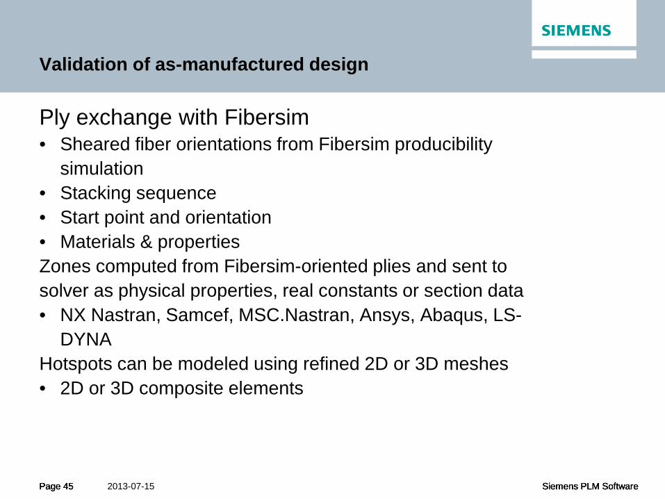
Validation of as-manufactured design
Ply exchange with Fibersim • Sheared fiber orientations from Fibersim producibility
simulation • Stacking sequence • Start point and orientation • Materials & properties Zones computed from Fibersim-oriented plies and sent to solver as physical properties, real constants or section data • NX Nastran, Samcef, MSC.Nastran, Ansys, Abaqus, LS-
DYNA Hotspots can be modeled using refined 2D or 3D meshes • 2D or 3D composite elements
Page 46 Siemens PLM Software Page 46 Siemens PLM Software 2013-07-15 Page 46 Siemens PLM Software
Validation of as-manufactured design
Structural evaluation can include the following analyses • Static linear • Nonlinear • Dynamic
• Transient, harmonic, random • Progressive damage • Nonlinear buckling and post-buckling • Delamination
Page 47 Siemens PLM Software Page 47 Siemens PLM Software 2013-07-15 Page 47 Siemens PLM Software
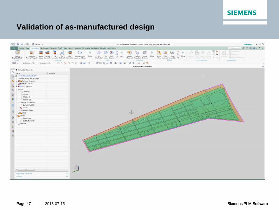
Validation of as-manufactured design
Page 48 Siemens PLM Software Page 48 Siemens PLM Software 2013-07-15 Page 48 Siemens PLM Software
Validation of as-manufactured design
Ply exchange with Fibersim • Modified ply data can be exchanged with Fibersim for
final incorporation in the composites design
Page 49 Siemens PLM Software Page 49 Siemens PLM Software 2013-07-15 Page 49 Siemens PLM Software
Lifecycle Flow of Composite Data
Preliminary Loft Design
Consumption of CAE Material Requirements
Selection of Design Method
Definition of Specifications
Generation of Layers\Plies
Simulation and Design
Manufacturing
Design\CAE Iteration
Design Release Deliverables and
Reporting
Enterprise Consumption of Composite Data
Fibersim Pre-CAD
Fibersim in CAD
Teamcenter MPP\PD\PS
Fibersim CAE
Exchange

Page 50 Siemens PLM Software Page 50 Siemens PLM Software 2013-07-15 Page 50 Siemens PLM Software
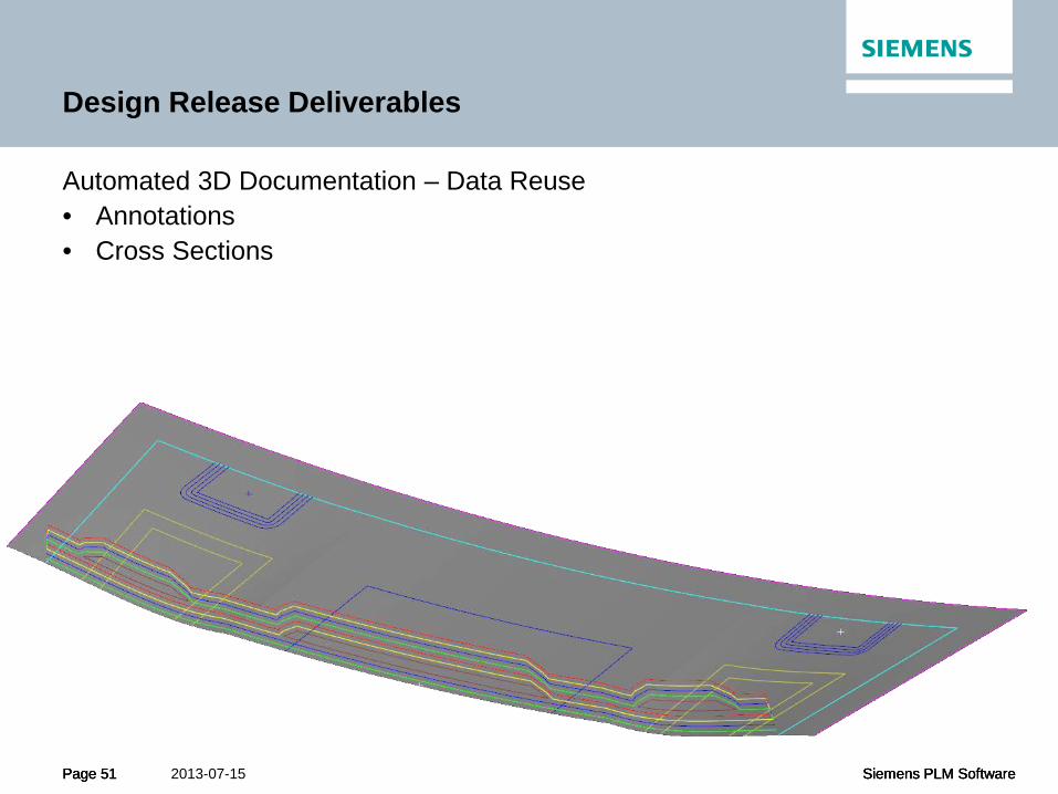
Design Release Deliverables
Automated 3D Documentation – Data Reuse • Annotations • Cross Sections
Ply tables Core sample
Material tables
Ply callout
Page 51 Siemens PLM Software Page 51 Siemens PLM Software 2013-07-15 Page 51 Siemens PLM Software
Design Release Deliverables
Automated 3D Documentation – Data Reuse • Annotations • Cross Sections

Page 52 Siemens PLM Software Page 52 Siemens PLM Software 2013-07-15 Page 52 Siemens PLM Software
Design Release Deliverables
Automated Inner Mold Line (IML) Generation • Final Part Solid • Tooling

Page 53 Siemens PLM Software Page 53 Siemens PLM Software 2013-07-15 Page 53 Siemens PLM Software
Design Release Deliverables
Automated Inner Mold Line (IML) Generation • Final Part Solid • Tooling

Page 54 Siemens PLM Software Page 54 Siemens PLM Software 2013-07-15 Page 54 Siemens PLM Software
Design Release Deliverables
Automated Plybook Generation
one or multiple views
generated
layup process displayed
flat pattern view
generated
tables auto completed

Page 55 Siemens PLM Software Page 55 Siemens PLM Software 2013-07-15 Page 55 Siemens PLM Software
Design Release Deliverables
Cutting and Nesting
Laser Projection
Automated Deposition

Page 56 Siemens PLM Software Page 56 Siemens PLM Software 2013-07-15 Page 56 Siemens PLM Software
Lifecycle Flow of Composite Data
Preliminary Loft Design
Consumption of CAE Material Requirements
Selection of Design Method
Definition of Specifications
Generation of Layers\Plies
Simulation and Design for
Manufacturing
Design\CAE Iteration
Design Release Deliverables and
Reporting
Enterprise Consumption of Composite Data
Fibersim Pre-CAD
Fibersim in CAD
Teamcenter MPP\PD\PS
Fibersim CAE
Exchange
Page 57 Siemens PLM Software Page 57 Siemens PLM Software 2013-07-15 Page 57 Siemens PLM Software
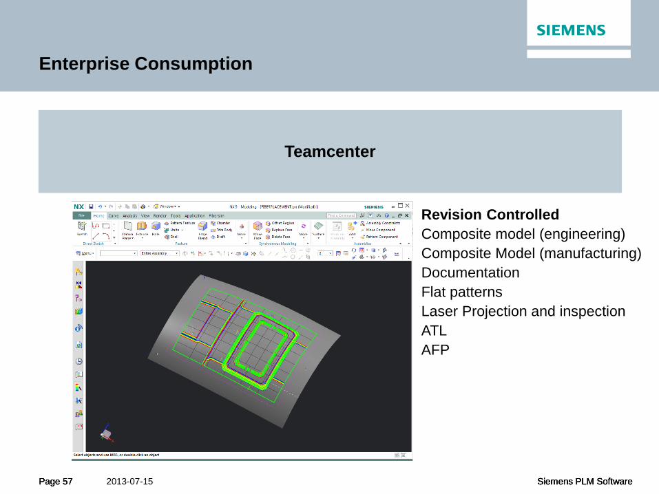
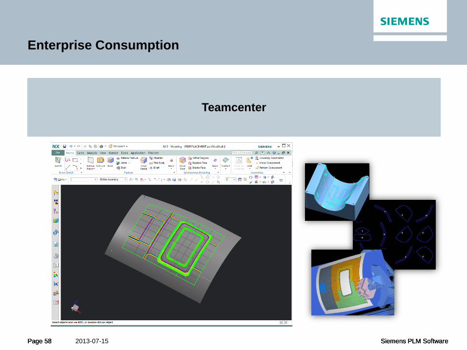
Enterprise Consumption
Teamcenter
Revision Controlled Composite model (engineering) Composite Model (manufacturing) Documentation Flat patterns Laser Projection and inspection ATL AFP
Page 58 Siemens PLM Software Page 58 Siemens PLM Software 2013-07-15 Page 58 Siemens PLM Software
Enterprise Consumption
Teamcenter
Page 59 Siemens PLM Software Page 59 Siemens PLM Software 2013-07-15 Page 59 Siemens PLM Software
References
Ref1: Aircraft Structural Design, Practical Design Information and Data on Aircraft Structures, Michael Chun-Yung Niu, Lockheed Aeronautical Systems Company, Burbank, California

Page 60 Siemens PLM Software Page 60 Siemens PLM Software 2013-07-15 Page 60 Siemens PLM Software
Contact Information
David Leigh Hudson Fibersim Product Manager Siemens PLM Software Specialized Engineering Software Waltham, MA [email protected]