comprod communications ltd.comprodcom.com/wp-content/uploads/2017/01/bda... · comprod...
TRANSCRIPT
COMPROD COMMUNICATIONS LTD.
Customer Instruction Manual
Model # BDA-806870
800 MHz BIDIRECTIONAL AMPLIFIER
Technical manual
2015, Comprod Communications LTD.
88 Industriel Blvd Boucherville, QC, J4B 2X2
Phone 1.800.641.1454 • Fax 1.800.641.4616
3405 N. Benzing Road Orchard Park, NY, USA 14127
Phone 1.800.603.1454 • Fax 1.800.554.1033
8 0 0 M H Z B I D I R E C T I O N A L A M P L I F I E R T E C H N I C A L M A N U A L
2
IMPORTANT: The integrator is responsible for its product to comply with IC ICES-003 & FCC Part 15, Subpart B – Unintentional Radiators. Final product must comply with unintentional radiators before declaring compliance of their final product to Part 15 of the FCC Rules and Industry Canada ICES-003.
8 0 0 M H Z B I D I R E C T I O N A L A M P L I F I E R T E C H N I C A L M A N U A L
3
Based on the philosophy of Anytime, Anywhere, and Anyplace, the 806-869 MHz amplifier module is designed for ease of use to be adaptable to various needs in the field. Recently developed technologies are applied. With the use of modern integrated circuits and RF components, the Comprod design ensures constant performance and a reliable amplifier unit.
The 800 MHz amplifier has also been designed with government agencies in mind. These agencies require the highest level of performance and quality for continuous duty solutions while providing maximum coverage. This amplifier module is aimed for the use in buildings, tunnels, government facilities, airports, providing the required communication throughout. The amplifier module helps to increase the coverage of RF communications in buildings or places where RF is unable to penetrate from the base station site. The Amplifier Module can be used in both Uplink and Downlink directions and it is connected to either a radiant cable, or a distributed antenna system at one end. At the other end it’s connected to the donor antenna.
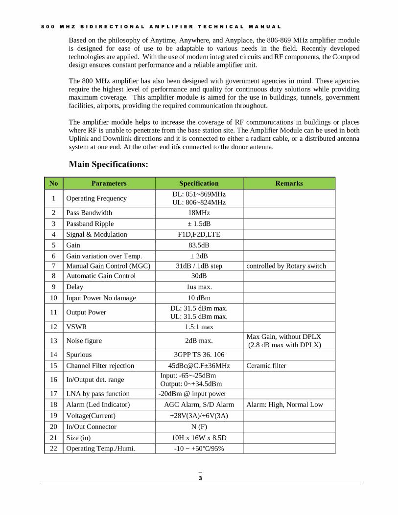
Main Specifications:
No Parameters Specification Remarks
1 Operating Frequency DL: 851~869MHz UL: 806~824MHz
2 Pass Bandwidth 18MHz 3 Passband Ripple ± 1.5dB
4 Signal & Modulation F1D,F2D,LTE
5 Gain 83.5dB
6 Gain variation over Temp. ± 2dB 7 Manual Gain Control (MGC) 31dB / 1dB step controlled by Rotary switch 8 Automatic Gain Control 30dB
9 Delay 1us max.
10 Input Power No damage 10 dBm
11 Output Power DL: 31.5 dBm max. UL: 31.5 dBm max.
12 VSWR 1.5:1 max
13 Noise figure 2dB max. Max Gain, without DPLX (2.8 dB max with DPLX)
14 Spurious 3GPP TS 36. 106
15 Channel Filter rejection [email protected]±36MHz Ceramic filter
16 In/Output det. range Input: -65~-25dBm Output: 0~+34.5dBm
17 LNA by pass function -20dBm @ input power
18 Alarm (Led Indicator) AGC Alarm, S/D Alarm Alarm: High, Normal Low 19 Voltage(Current) +28V(3A)/+6V(3A) 20 In/Out Connector N (F) 21 Size (in) 10H x 16W x 8.5D
22 Operating Temp./Humi. -10 ~ +50℃/95%
8 0 0 M H Z B I D I R E C T I O N A L A M P L I F I E R T E C H N I C A L M A N U A L
4
Block Diagram Details
- The 800 MHz Amplifier module contains a (Low Noise Amplifier) LNA designed to detect a very weak signal. This stage is bypassed if the signal level at the input is higher than -20dBm
- The LNA is followed by an Automatic Gain Control (AGC). The AGC circuit measures composite
power level at the VGA input and adjusts the gain automatically, in order to maintain a constant signal level at the VGA output delivered to the Power Amplifier (PA). Channel filters are inserted, in order to reject adjacent channel signals and to improve the signal quality.
- The PA provides good performance for both linearity and efficiency. This amplifier has a heat sink mounted to it and it has a high compression point and 3rd order Intercept point.
- The unit can operate with AC or DC power supplies. The main AC input accepts 50/60 Hz with a 115
to 220 V AC power source. The Power Supply Unit (PSU) converts AC to DC voltages to supply DC power to the amplifiers, monitoring and control units. The unit can be fed directly with DC power, by selecting the DC option on the AC/DC switch and connecting +24 to 27 V to the DC input connector. The operator must ensure that this external DC power supply is compliant with FCC limits on radiated and conducted emissions.
- The unit does not have a built-in UPS/Battery system. In case of inconsistency in the AC line power, surge protection, short blackouts, high crossover time from the line AC to generator power, circuit breaker for short circuit and overload protection, etc., an external UPS/Battery system is recommended.
- The unit has two duplexers; one at the BTS port allowing the use for only one donor antenna for both UL and DL. The second duplexer is mounted at the Service DAS antenna port. These duplexers provide at least 100 dB isolation at each end between the two paths.
- A set of manual gain controls (MGC), ranging from 0 to 30 dB in 1 dB steps are also added in the chain for additional attenuation if it is needed.

8 0 0 M H Z B I D I R E C T I O N A L A M P L I F I E R T E C H N I C A L M A N U A L
5
Figure 1: Block diagram of the 800 MHz bidirectional amplifier
Led indicator Alarm and Manual level control.
- The unit has visual alarms using LED indicators for the following conditions; AGC, S/D and Power.
o AGC: alarm turns red when the AGC is not delivering any attenuation. This can happen in two situations. Either the AGC is turned off by the user (see monitoring and control section) or if the signal at input of the DL is too weak. This is not necessarily a failure. It can just be a warning that the signal from the BTS is too weak.
o S/D: The shutdown indicator turns red when the system is in automatic shutdown. This happens when the internal temperature is too high or when the output power exceeds the maximum limit allowed. When the RF module is turned off by the user (see monitoring and control section) the S/D indicator will start flashing.
o The Power indicator turns red when the RFM is not receiving the correct DC power.
8 0 0 M H Z B I D I R E C T I O N A L A M P L I F I E R T E C H N I C A L M A N U A L
6
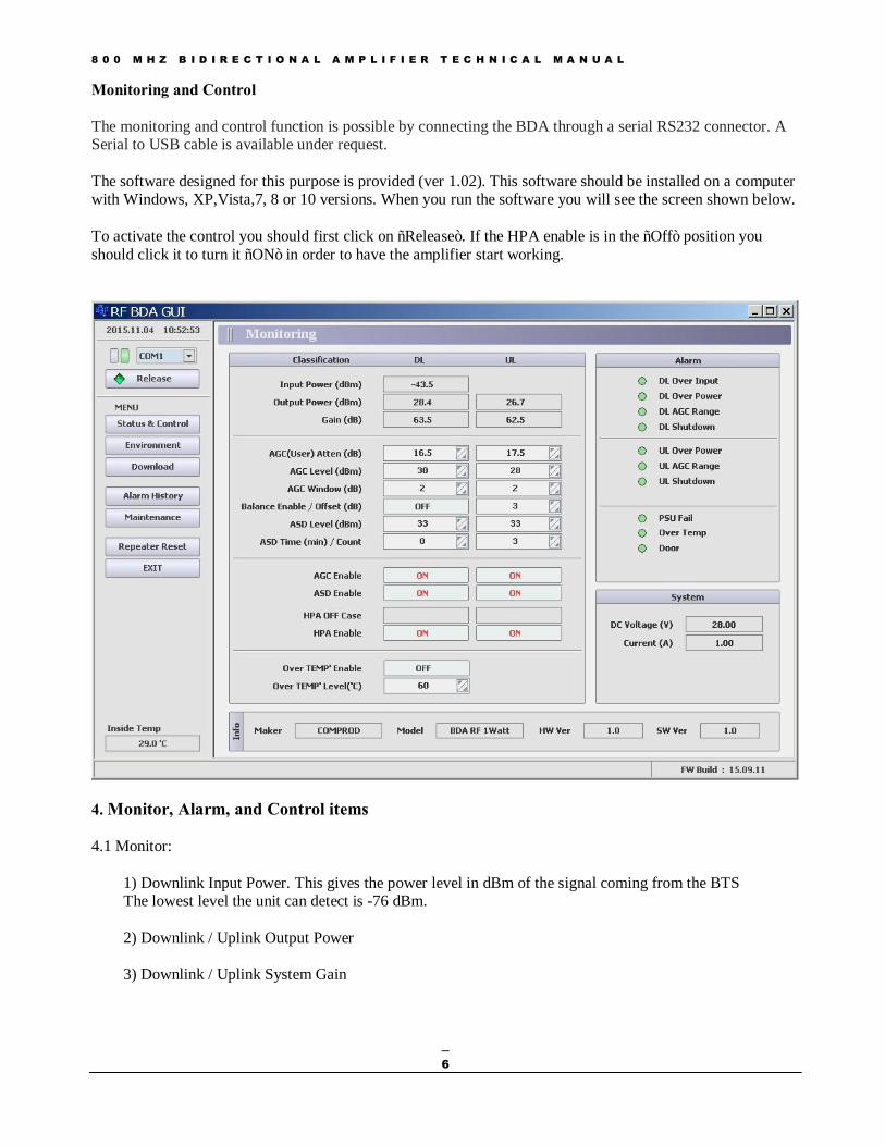
Monitoring and Control The monitoring and control function is possible by connecting the BDA through a serial RS232 connector. A Serial to USB cable is available under request. The software designed for this purpose is provided (ver 1.02). This software should be installed on a computer with Windows, XP,Vista,7, 8 or 10 versions. When you run the software you will see the screen shown below. To activate the control you should first click on “Release”. If the HPA enable is in the “Off” position you should click it to turn it “ON” in order to have the amplifier start working.
4. Monitor, Alarm, and Control items 4.1 Monitor:
1) Downlink Input Power. This gives the power level in dBm of the signal coming from the BTS The lowest level the unit can detect is -76 dBm. 2) Downlink / Uplink Output Power 3) Downlink / Uplink System Gain
8 0 0 M H Z B I D I R E C T I O N A L A M P L I F I E R T E C H N I C A L M A N U A L
7
4) Downlink / Uplink AGC Attenuation. Automatic attenuation delivered by the AGC to maintain the output level constant. When this value shows “0” it is because the input power is lower than -53 dBm. If it is zero in the Downlink path the AGC alarm will turn red. 5) DC voltage / current monitor. It shows the DC voltage and current to the RF unit. 6) System temp. Shows the current system temperature.
4.2 Alarms:
1) Downlink input over power. Turns red when the input power from the BTS exceeds the maximum predefined setting. 2) Downlink / Uplink output overload. 3) AGC range alarm. 4) Downlink / Uplink Shutdown. Turns red when a shutdown occurs because of overtemp or being over the output power limit. It will be flashing when it is shut down by the user. 5) PSU alarm. 6) Over temp. Alarm. 7) Door Alarm.
4.3 Control:
1) Downlink / Uplink HPA on/off 2) Downlink / Uplink gain control 3) Downlink / Uplink AGC on/off 4) Downlink / Uplink shutdown on/off 5) MCU Reset 6) Alarm limit
4.4 Additional Information:
1) Software Version 2) Vendor name 3) Model name 4) Time 5) Alarm history 6) Maintenance history
8 0 0 M H Z B I D I R E C T I O N A L A M P L I F I E R T E C H N I C A L M A N U A L
8
Unpacking
1) If the shipping box is damaged, do not open it, take a picture and contact the freight carrier for a claim.
2) If the shipping box is not damaged, the 800 MHz BDA should be unpacked soon after delivery and carefully inspected for possible shipping damage. It is the customer’s responsibility to file claims with the freight carrier if damage is suspected and that is usually limited to a certain time period after delivery.
3) Carefully compare the packing slip(s) against the package contents to verify the receipt of all expected items.
4) Retain all product documentation and make sure that manuals are forwarded to the appropriate site management, installation and service personnel.
Lightning Protection Although relatively rugged, lightning can damage the internal working mechanisms inside the BDA. We recommend the installation of a lightning surge suppressor in the transmission line where it enters the building prior to the BDA. The suppressor should be grounded to the building ground bus at the transmission line entry point. Choose a suppressor that will handle the expected amount of input power from the BDA to the donor antenna.
Antenna Installation Buildings that are not designed or upgraded for antenna systems need special attention for antenna mounting, equipment installation and cable runs. There are many variables involved in the design of a DAS system (distributed antenna system). There are structural requirements for the location of the outdoor antenna (Donor); masts, towers, building structure for handling wind and ice loading. -Protection of antennas and cables from building occupants and general human interaction. - Installers/designers must be aware of general seating, foot traffic areas and different access points. - All Antennas must be designed for the working frequency, and ensure they meet the exposure
requirements. - The donor antenna and distribution antennas must be have 12 dB + the Maximum gain of the amplifier of isolation between them. Less isolation will cause the module to overload and oscillation will occur which may result in damage to the amplification module. - Antennas should be mounted following the manufacture’s guidelines for RF connection and be affixed to the building or location of the desired signal. - All cables used in the DAS system shall be 50 Ohms and clamped properly to ensure the cables 50 Ohm impedance characteristics. Improper clamps will change the impedance of the cable at that location thus changing the efficiency of the system. - Antenna placement through the DAS system is important to produce a balanced, distributed signal. The use of correct decouplers, power dividers, and signal taps is important to promote a balanced system.

8 0 0 M H Z B I D I R E C T I O N A L A M P L I F I E R T E C H N I C A L M A N U A L
9
BDA INSTALLATION DO NOT APPLY A.C. POWER TO THE BDA UNTIL CABLES ARE CONNECTED TO BOTH PORTS OF THE BDA AND THE ANTENNAS. 1. Mount the BDA on the wall with the RF connectors pointing DOWN. Using appropriate screws and anchors, attach the BDA to the wall at the four mounting holes on the side flanges. 2. Ensure that the isolation between the donor antenna and the service antenna is at least 12 dB greater than the BDA gain. (Use the higher of the Uplink and Downlink gains reported on the BDA test data sheet). 3. Connect the cable from the donor antenna to the BDA connector labeled “BASE” and the cable from the service antennas to the BDA connector labeled “MOBILE”. 4. Open the door of the metallic box of the BDA and verify that both of the PSU switches are in their factory preset “ON” positions. Close the panels. 5. Connect the AC power cord to the BDA and then to the power source. Verify that the “Power ON” lamp is illuminated. 6. Connect the computer with the software v1.02 installed via RS 232 serial connector or via a USB port. 7. On the RF_BDA_GUI make sure that AGC Enable, ASD Enable and HPA Enable functions are all turned ON. Installation of the BDA is now complete. To adjust the gain controls to suit the specific signal environment, refer to the section on Monitoring and Control.
8 0 0 M H Z B I D I R E C T I O N A L A M P L I F I E R T E C H N I C A L M A N U A L
10
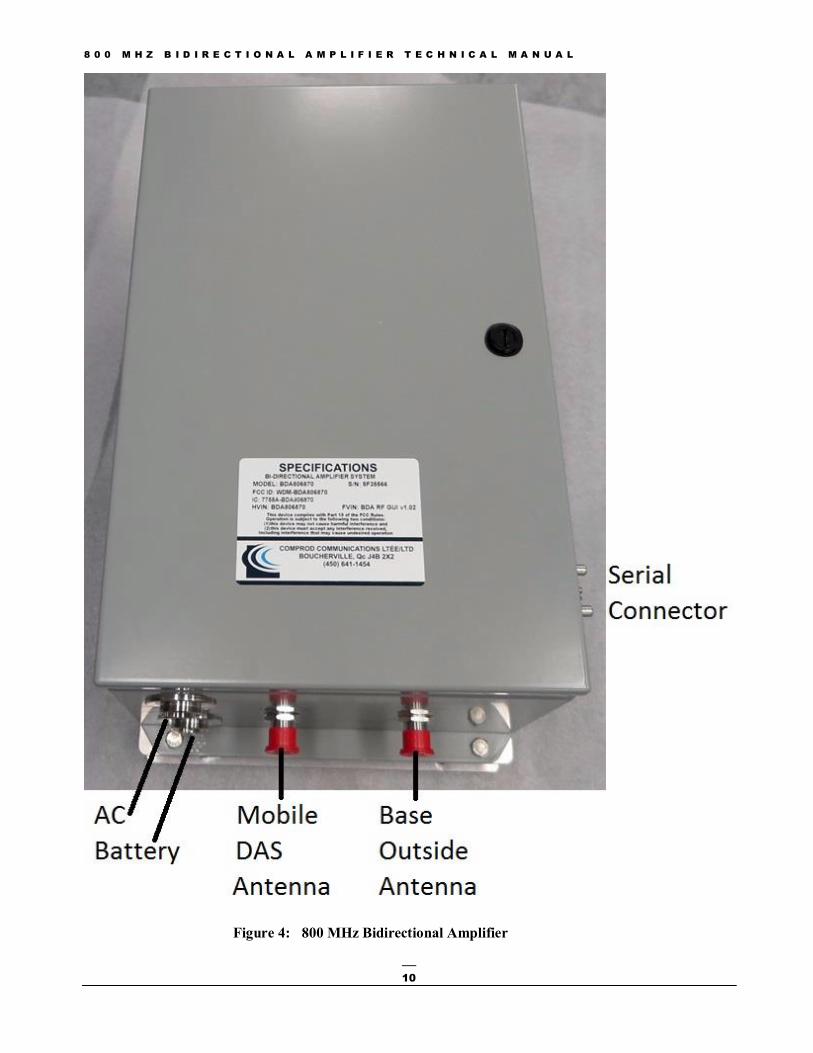
Figure 4: 800 MHz Bidirectional Amplifier
8 0 0 M H Z B I D I R E C T I O N A L A M P L I F I E R T E C H N I C A L M A N U A L
11
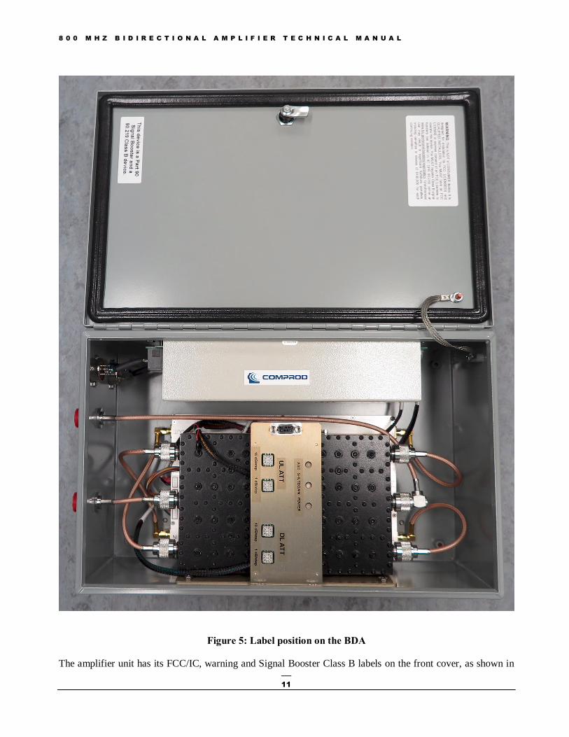
Figure 5: Label position on the BDA
The amplifier unit has its FCC/IC, warning and Signal Booster Class B labels on the front cover, as shown in
8 0 0 M H Z B I D I R E C T I O N A L A M P L I F I E R T E C H N I C A L M A N U A L
12
the above picture. These labels must not be removed.
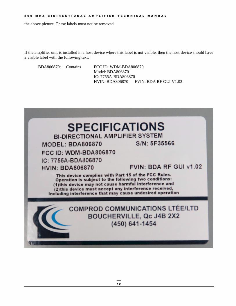
If the amplifier unit is installed in a host device where this label is not visible, then the host device should have a visible label with the following text:
BDA806870: Contains FCC ID: WDM-BDA806870 Model: BDA806870
IC: 7755A-BDA806870 HVIN: BDA806870 FVIN: BDA RF GUI V1.02
8 0 0 M H Z B I D I R E C T I O N A L A M P L I F I E R T E C H N I C A L M A N U A L
13
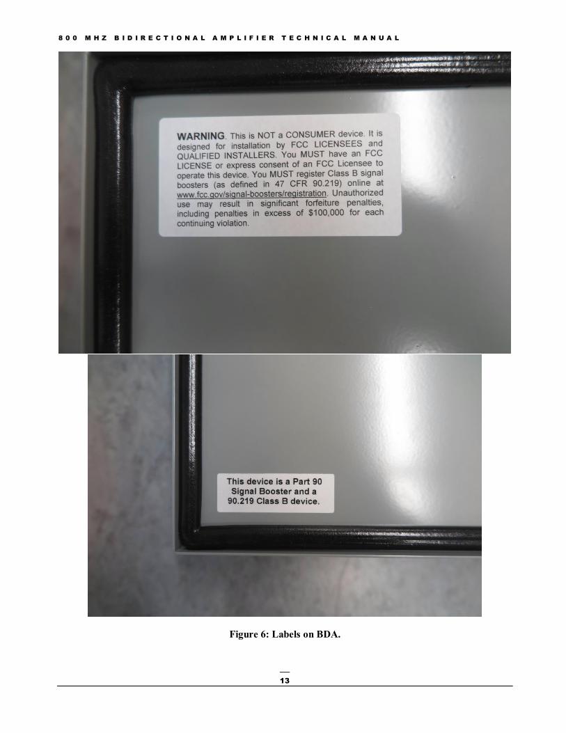
Figure 6: Labels on BDA.
8 0 0 M H Z B I D I R E C T I O N A L A M P L I F I E R T E C H N I C A L M A N U A L
14
Warnings and Notices
WARNING: Changes or modifications not expressly approved by Comprod Communications could void the user’s authority to operate the equipment
WARNING: To satisfy RF exposure requirement FCC: The RF exposure safe separation distance is 20cm IC: The RF exposure safe separation distance is 21.03cm Notice: This equipment has been tested and found to comply with the limits for a Class A digital device, pursuant to Part 15 of the FCC Rules. These limits are designed to provide reasonable protection against harmful interference when the equipment is operated in a commercial environment. This equipment generates, uses, and can radiate radio frequency energy and, if not installed and used in accordance with the instruction manual, may cause harmful interference to radio communications. Operation of this equipment in a residential area is likely to cause harmful interference in which case the user will be required to correct the interference at his own expense.
End of Document