conceptual design of tall building - ci · pdf fileconceptual design of tall building s l lee,...
TRANSCRIPT
Conceptual design of tall building
S L Lee, National University of Singapore, Singapore S Swaddiwudhipong, National University of Singapore, Singapore
25th Conference on OUR WORLD IN CONCRETE & STRUCTURES: 23 - 24 August 2000, Singapore
Article Online Id: 100025001
The online version of this article can be found at:
http://cipremier.com/100025001
This article is brought to you with the support of
Singapore Concrete Institute
www.scinst.org.sg
All Rights reserved for CI‐Premier PTE LTD
You are not Allowed to re‐distribute or re‐sale the article in any format without written approval of
CI‐Premier PTE LTD
Visit Our Website for more information
www.cipremier.com
25th Conference on Our World in Concrete & Structures: 23 - 24 August 2000, Singapore
Conceptual design of tall building
S L Lee, National University of Singapore, Singapore S Swaddiwudhipong, National University of Singapore, Singapore
ABSTRACT
The paper describes the conceptual design and wind load analysis of tall buildings. Early participation of engineers interacting with architects in conceptual design will lead to efficient and cost effective structural system. The lateral stiffness of the building is provided by the interaction of core wall and frame tubes which should be properly distributed such that the building will deflect mainly in the direction of the applied force without inducing significant response in other directions and twist. Core wall contributes to flexural and torsional rigidities which are essential in the lower quarter of the building while closed periphery frame tube comprising deep spandrel beams and flat columns provides effective resistance to lateral loads in the upper three-quarters of the building. Structural response in three principal directions due to wind load are described. The performances of building in terms of peak drift and maximum acceleration under wind load are discussed.
1. Introduction
Continual economic growth in East and Southeast Asia in the past few decades is manifested by the rapid development of infrastructure in major cities in the region. A large number of taller buildings are constructed where lateral response of such structures have become critical and measures have to be taken to ensure a robust and safe structure satisfying stipulated serviceability requirements. These can be achieved economically through well-conceived structural systems in which structural members are designed to serve several functions and integrated to resist lateral loads effectively. The cost effectiveness is further enhanced if the system is considered with closed consultation between architects and structural engineers at an early stage. The interaction of core walls with periphery frame tube and/or bundle of frame tubes and integrated design of the basement contribute significantly to lateral rigidities of the building. The latter, besides providing the needed resistance to lateral loads through direct bearing action, also renders additional premium spaces for shops, supermarkets and car park. The up-down basement construction, if adopted, permits the construction activities of the superstructure and substructure to overlap resulting in about 10-20% reduction of the construction time [1-4]. This paper describes the conceptual design and wind load analysis of tall buildings including a brief description of a 70-storey reinforced concrete building.
2. Conceptual Design of Structural System
The ratio of building height above any section to its least cross sectional dimension is usually kept below 6 depending on the intensity and severity of wind and earthquake loads. Lower ratio applies to buildings located in severe earthquake zone and/or frequent strong wind incidences. The design of tall buildings excepting the frame tube members and the shear walls, in mild wind environment and/or low seismic zone is usually proportioned initially based on gravity load requirements and checked against appropriate lateral loads using established computer package
1
such as ETABS or GTSTRUDL. Either allowable stresses in structural members are increased or the load factor reduced as specified by building code if both vertical and lateral loads are considered together. Additional reinforcement and/or increase in member sizes may be required in the latter case.
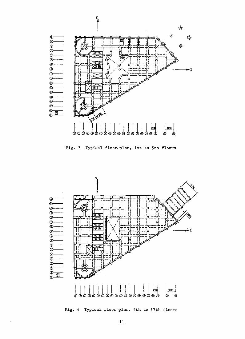
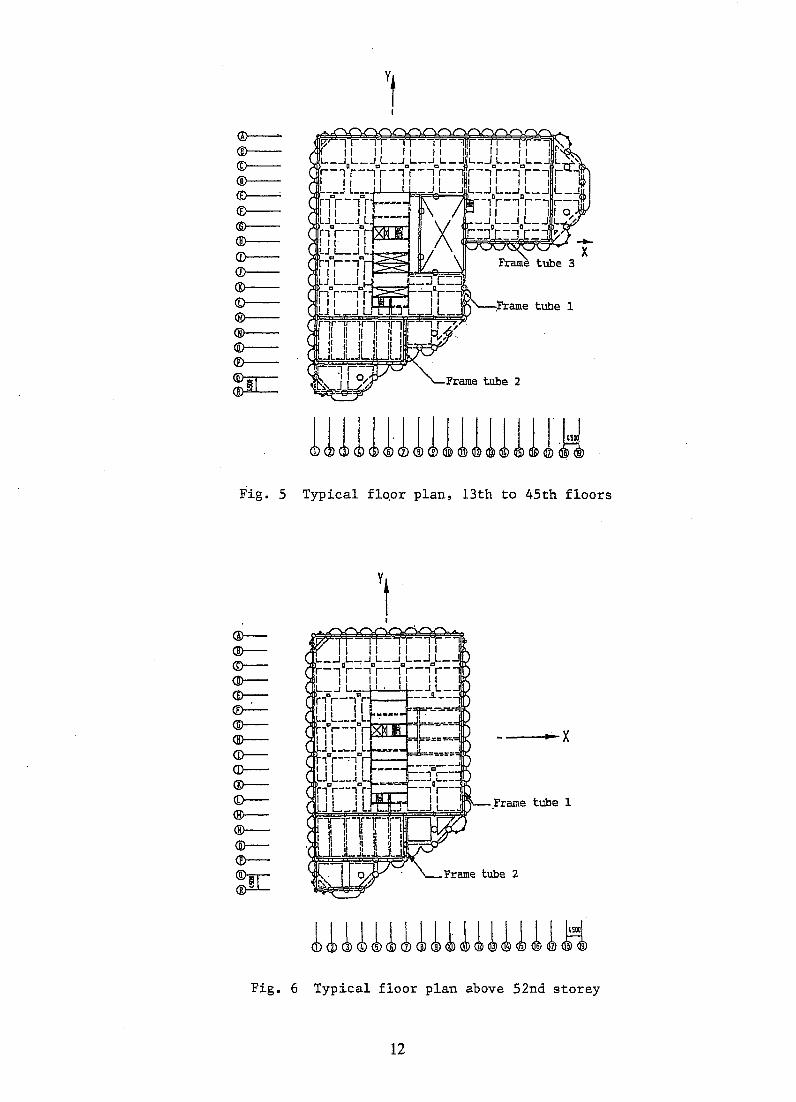
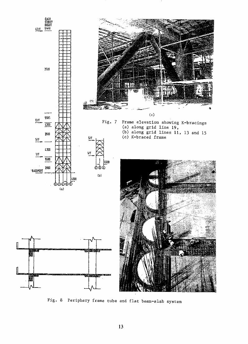
In many tall buildings especially where the plan and configuration are irregular, the core wall is placed eccentrically due to architectural requirements. An example is the 70-storey reinforced concrete building constructed in Bangkok of which, the perspective and typical floor plans are shown in Figs. 1-6. In this building, the core wall housing the lift and staircases are located eccentrically to the left of the building. To alleviate the adverse effect of this eccentricity and to improve the torsional rigidity, two shear walls of 1.5 m thick and a shear wall of 1.0 m thick are introduced from grid points A-1 to A-5, R-1 to 0-5 and A-19 to F-21 respectively as shown in Fig. 2. The 1 m thick shear wall is terminated at the first floor level at the main entrance but the two 1.5 m walls are present upto the 13th floor. A line of braced frames (Fig. 7) is provided along grid line 19 between grid lines C and G from the basement B6 to 1st floor and 5th to 13th floors as shown in Figs. 2 and 4 respectively. This is supplemented by three other braced frames at grid lines 11, 13 and 15 between grid lines A and C from 1 st to 5th floors (Fig. 3) to provide the continuity of the transfer of lateral load at these levels. Finally, two smaller frame tubes are placed on the two adjacent sides of the main tube as indicated in Fig. 5, to cater for the eccentricity in the upper portion of the buildings. One of these smaller frame tubes gradually disappears above the 46th floor (Fig. 6). In this building the periphery frame tube consists of deep spandrel beams and flat columns (Fig. 8). In building where there is no balcony, the periphery spandrel beam can be rendered deeper by upturning the beam to the bottom of the window sill. Greater depth can be allowed for the spandrel beams between the windows and/or doors in consecutive floors without increasing floor to floor height. The shear and torsional rigidities can be further enhanced through the closer spacing of periphery columns in the upper three quarters of the building.
Conventional flat slab is adopted for the ground floor and the basement car park with 9 m column spacing to facilitate car parking. A flat beam and slab system (Fig. 8) which is lighter is adopted for all other floors to carry vertical loads only. In the latter, the shear forces and bending moments in the column strip are resisted by the flat beam and the smaller shear forces and bending moment in the middle strip is resisted by the thin slab. This permits a lower storey height resulting in a substantial reduction in total building height and weight and thus allowing a leaner substructure system. Composite steel reinforced concrete columns are employed in the lower part of the building and ordinary reinforced concrete columns are used in the upper portion where the column loads are lighter. Loads from steel stanchions are transferred to reinforced concrete bored piles through shear studs. The use of composite steel reinforced concrete column for the lower portion of the building is necessary to reduce substantially the size of the columns and, more importantly, the steel stanchion is required if up-down construction method is adopted to dispense with the temporary excavation support system and to reduce the time of construction.
3. Substructure System
Tall buildings are usually supported by reinforced concrete rafts of 2.0 - 4.0m thick under the tower but reduced to 1.5 - 2.0m under the podium, if any. The raft usually rests on piles the type of which depends on the soil conditions at the site. Due to the high column load and limited building area for tall buildings located in city centres, the piles are often spaced close together and in many cases, less than 3 pile diameter centre to centre. The pile interaction resulting from the close spacing has to be considered for the pile design by reducing the frictional capacity of the pile. The base of bored piles is sometimes grouted using high pressure stage grouting with tube-a-manchettes to increase bearing capacity and reduce settlement in the foundation system. The applied grouting pressure, up to 60 bars, is also a form of test loading the end bearing and frictional capacity of the pile. With base grouting, the increase in the cost of foundation is about 10% but the increase in ultimate bearing capacity is about 25-30% in this case. For deep excavation with the presence of deep soft clay layer at this site located in the vicinity of old buildings, diaphragm wall supported by the permanent basement slabs using top-down construction method is adopted for basement construction. The system provides a rigid excavation support system dispensing unnecessary cost for temporary works. In up-down approach, the construction of the substructure and superstructure may proceed concurrently saving the construction time by 10-20% in this case.
2
4. Structural Modelling
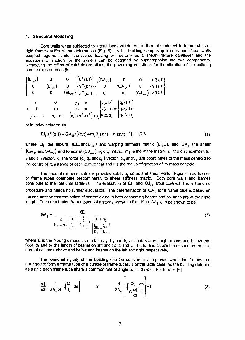
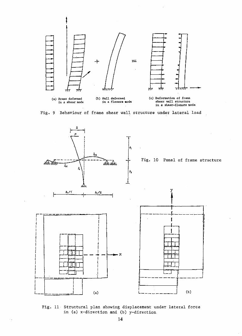
Core walls when subjected to lateral loads will deform in flexural mode, while frame tubes or rigid frames suffer shear deformation (Fig. 9). A tall building comprising frames and shear walls coupled together under transverse loading will deform as a shear- flexure cantilever and the equations of motion for the system can be obtained by superimposing the two components. Neglecting the effect of axial deformations, the governing equations for the vibration of the building can be expressed as [5]
[(Elf) 0 o r(z.t)} [(GA~) 0 o ]u.(z.t)} (El xx ) o VIV (z, t) - 0 (GAyy ) o v"(z, t)
0 (Elww) e iv (z, t) 0 0 (GJww ) e "(z, t)
m 0 y, m lr~t)} rz.t)} +[ 0 m Xc m v(z, t) = qv(z, t)
-Yc ·m Xc ·m (x~+y~+r2).m (3'(z,t) qe(Z,t)
or in index notation as
(1)
where Elij the flexural (Elyy andElxx ) and warping stiffness matrix (Elww), and GAij the shear
(GAxx andGAyy) and torsional (GJww ) rigidity matrix, mij is the mass matrix, Uj the displacement (u,
v and e ) vector, qi the force (qu, qv and qe ) vector, Xc and y c are coordinates of the mass centroid to
the centre of resistance of each component and r is the radius of gyration of its mass centroid.
The flexural stiffness matrix is provided solely by cores and shear walls. Rigid jointed frames or frame tubes contribute predominantly to shear stiffness matrix. Both core walls and frames contribute to the torsional stiffness. The evaluation of Elij and GJ33 from core walls is a standard
procedure and needs no further discussion. The determination of GAij for a frame tube is based on
the assumption that the pOints of contraflexure in both connecting beams and columns are at their mid length. The contribution from a panel of a storey shown in Fig. 10 to GAij can be shown to be
6E GAij = --2--;:[=-h-f--h-~ "'"]--h-
1-+-h-
2-
h1 +h2 ~+~ + [k+~] b1 b2
(2)
where E is the Young's modulus of elasticity, h1 and h2 are half storey height above and below that floor, b1 and b2 the length of beams on left and right, and IC1' Ic2' Ib1 and Ib2 are the second moment of area of columns above and below and beams on the left and right respectively.
The torsional rigidity of the building can be substantially improved when the frames are arranged to form a frame tube or a bundle of frame tubes. For the latter case, as the building deforms as a unit, each frame tube share a common rate of angle twist, dq> jdz. For tube ex [6]
or (3)
3
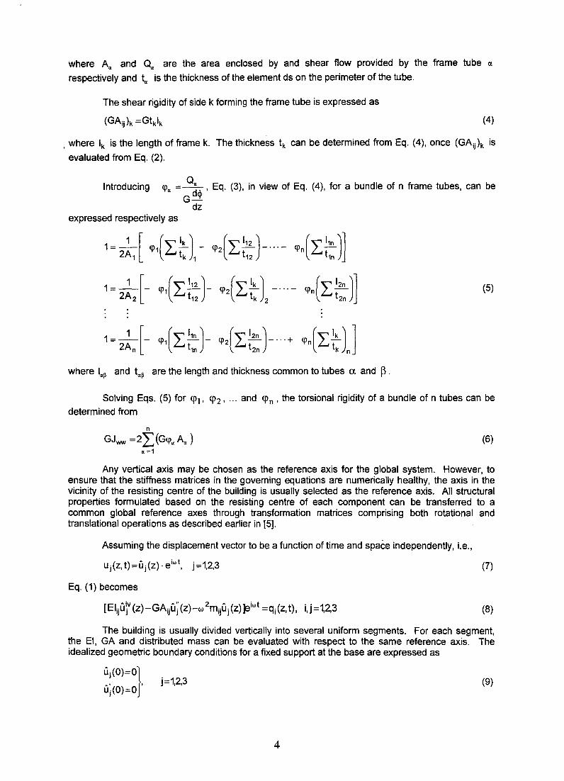
where A", and Q", are the area enclosed by and shear flow provided by the frame tube IX
respectively and t", is the thickness of the element ds on the perimeter of the tube.
The shear rigidity of side k forming the frame tube is expressed as
(GAij)k =Gtklk (4)
. where Ik is the length of frame k. The thickness tk can be determined from Eq. (4), once (GAij)k is
evaluated from Eq. (2).
Introducing <p", = ~<I> ' Eq. (3), in view of Eq. (4), for a bundle of n frame tubes, can be G-
dz expressed respectively as
1=_1 [<P1(L~) - <P2(L~)-"'- <pn(L~)l 2A1 tk 1 t12 t1n
1~2;2[- ~{L:::)- ~2(L::)2 ~"(L::)l (5)
where I",~ and t",~ are the length and thickness common to tubes ex. and ~.
Solving Eqs. (5) for <PI' <P2' ... and <Pn' the torsional rigidity of a bundle of n tubes can be determined from
n
GJww =2L(G<p",A",) (6) '" ;1
Any vertical axis may be chosen as the reference axis for the global system. However, to ensure that the stiffness matrices in the governing equations are numerically healthy, the axis in the vicinity of the reSisting centre of the building is usually selected as the reference axis. All structural properties formulated based on the resisting centre of each component can be transferred to a common global reference axes through transformation matrices comprising both rotational and translational operations as described earlier in [5].
Assuming the displacement vector to be a function of time and space independently, i.e.,
uj(z,t)=Uj(z)·eiwt. j=1,2,3 (7)
Eq. (1) becomes
[Eliju\V (z)-GAiju; (z)-w 2mijUj(z) ]eiwt =qi (z, t), i,j=t2,3 (8)
The building is usually divided vertically into several uniform segments. For each segment, the EI, GA and distributed mass can be evaluated with respect to the same reference axis. The idealized geometric boundary conditions for a fixed support at the base are expressed as
~ j=1,2,3 ~ J,'(O)=O}, Uj(O)=O
(9)
4
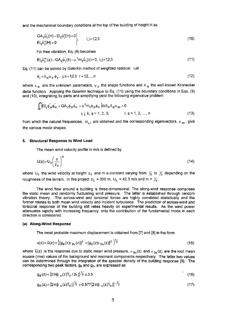
and the mechanical boundary conditions at the top of the building of height H as
GAjjU; (H) - Elijuj'(H) =0]
Eljjuj(H)=O ' i,j = 1,2,3
For free vibration, Eq. (8) becomes
Eljju\V (z)- GAiju~ (z)-w 2mjju j (z)=O, i, j = 1,2,3
Eq. (11) can be solved by Galerkin method of weighted residual. Let
U j = Os{Xsr<P jr' j, s= 1,2,3; r =1,2, ... , n
(10)
(11 )
(12)
where IX sr are the unknown parameters, 4' jr the shape functions and 0 sj the well-known Kronecker
delta function. Applying the Galerkin technique to Eq. (11) using the boundary conditions in Eqs. (9) and (10), integrating by parts and simplifying yield the following eigenvalue problem:
(13)
from which the natural frequencies, O)q, are obtained and the corresponding eigenvectors, IX qs ' give
the various mode shapes.
5. Structural Response to Wind Load
The mean wind velocity profile in mls is defined by
(14)
where Uo the wind velocity at height Zo and m a constant varying from is to ~ depending on the
roughness of the terrain. In this project Zo = 300 m, Uo = 42.3 mls and m = y,;.
The wind flow around a building is three-dimensional. The along-wind response comprises the static mean and randomly fluctuating wind pressure. The latter is established through random vibration theory. The across-wind and torsional forces are highly correlated statistically and the former relates to both mean wind velocity and incident turbulence. The prediction of across-wind and torsional response of the building still relies heavily on experimental results. As the wind power attenuates rapidly with increasing frequency, only the contribution of the fundamental mode in each direction is considered.
(a) Along-Wind Response
The most probable maximum displacement is obtained from [7] and [8] in the form
u(z) = u(z) + {[gB (zp Bu (Z)]2 + [go (zp ou (Z)]2 p~ (15)
where u(z) is the response due to static mean wind pressure, a Bu(Z) and a ou(z) are the root mean
square (rms) values of the background and resonant components respectively. The latter two values can be determined through the integration of the spectral density of the building response [9]. The corresponding two peak factors, g8 and go, are expressed as
gB(z)={2In[A u(z)To 12rc]}}i =3.5 (16)
go(z)={2In[A u(Z)To]}}i +0.577{2In[). u(z)To]}-~ (17)
5
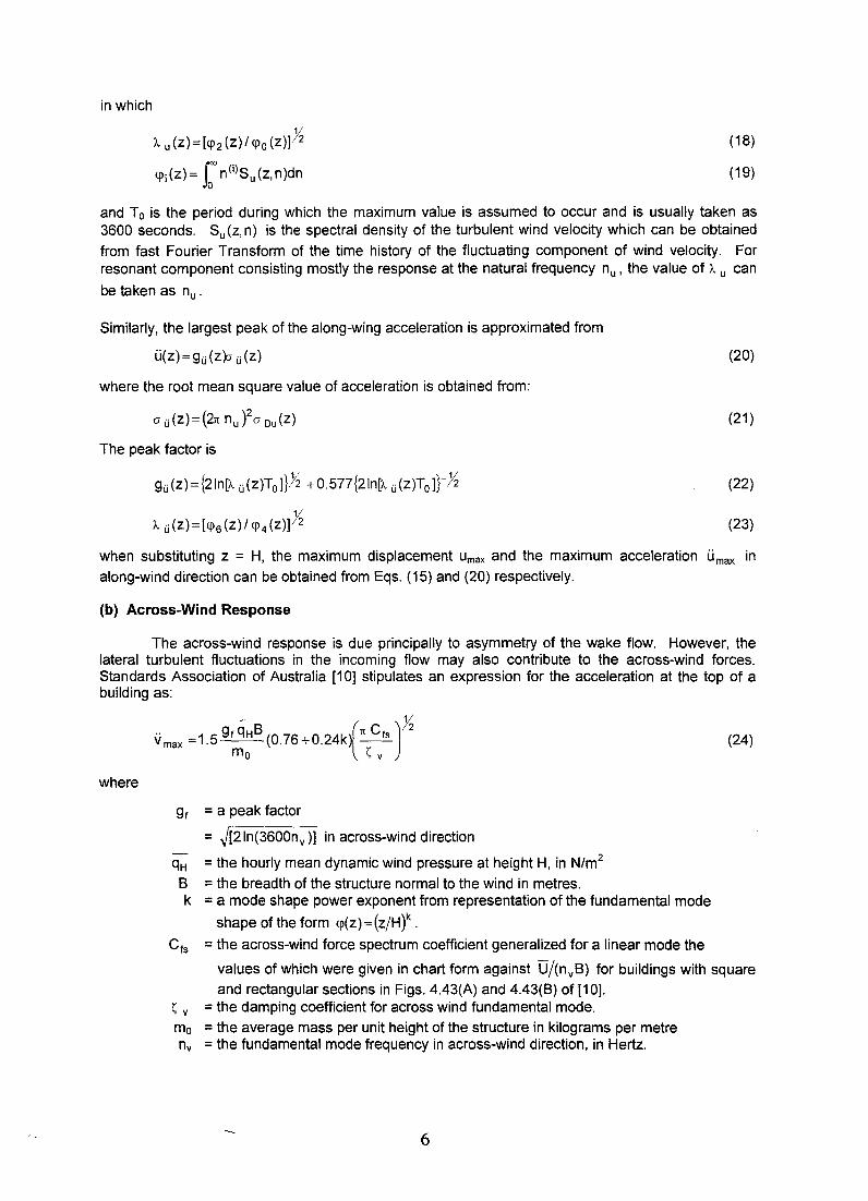
in which
A. u (Z)=[<P2 (Z)/ <Po (z)]h
<pj(z)= r n(i)Su(z,n)dn
(18)
(19)
and To is the period during which the maximum value is assumed to occur and is usually taken as 3600 seconds. Su (z, n) is the spectral density of the turbulent wind velocity which can be obtained
from fast Fourier Transform of the time history of the fluctuating component of wind velocity. For resonant component consisting mostly the response at the natural frequency nu, the value of A. u can
be taken as nu.
Similarly, the largest peak of the along-wing acceleration is approximated from
u(z)=gu(zp u(z)
where the root mean square value of acceleration is obtained from:
o u (z) = (2n nu )20 Du (z)
The peak factor is
gu(z)={2In[A. u(Z)Ta]}h +0.577{2In[A. u(z)Ta]}-h
A. u(Z)=[<P6(Z)/ <P4(z)]h
(20)
(21 )
(22)
(23)
when substituting z = H, the maximum displacement Umax and the maximum acceleration umax in
along-wind direction can be obtained from Eqs. (15) and (20) respectively.
(b) Across-Wind Response
The across-wind response is due principally to asymmetry of the wake flow. However, the lateral turbulent fluctuations in the incoming flow may also contribute to the across-wind forces. Standards Association of Australia [10] stipulates an expression for the acceleration at the top of a building as:
where
- h v max = 1.5 gf qH
B (0.76 + 0.24k)(n Cfs ) 2
ma ~ v
gf = a peak factor
= J[2In(3600nv)] in across-wind direction
qH = the hourly mean dynamic wind pressure at height H, in N/m2
B = the breadth of the structure normal to the wind in metres. k = a mode shape power exponent from representation of the fundamental mode
shape of the form <p(z) = (z/Ht .
Cfs = the across-wind force spectrum coefficient generalized for a linear mode the
(24)
values of which were given in chart form against D/(nvB) for buildings with square and rectangular sections in Figs. 4.43(A) and 4.43(8) of [10].
~ v = the damping coefficient for across wind fundamental mode.
ma = the average mass per unit height of the structure in kilograms per metre nv = the fundamental mode frequency in across-wind direction, in Hertz.
6
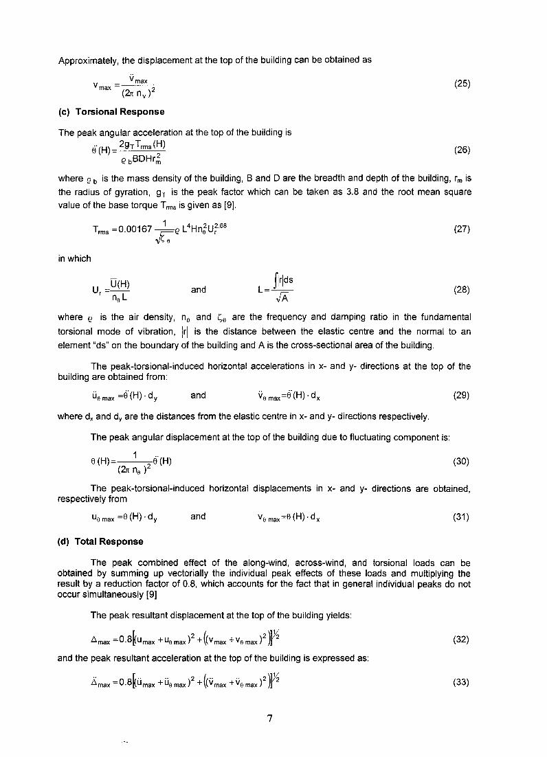
Approximately, the displacement at the top of the building can be obtained as
(25)
(c) Torsional Response
The peak angular acceleration at the top of the building is
Ei' (H) = 29T Trms (H)
e bBDHr~ (26)
where e b is the mass density of the building, Band D are the breadth and depth of the building, rm is
the radius of gyration, gT is the peak factor which can be taken as 3.8 and the root mean square
value of the base torque Trms is given as [9].
in which
u = U(H) r n L s
and
(27)
flrlds L=--
fA (28)
where e is the air density, ns and ss are the frequency and damping ratio in the fundamental
torsional mode of vibration, Irl is the distance between the elastic centre and the normal to an
element "ds" on the boundary of the building and A is the cross-sectional area of the building.
The peak-torsional-induced horizontal accelerations in x- and y- directions at the top of the building are obtained from:
and (29)
where dx and dy are the distances from the elastic centre in x- and y- directions respectively.
The peak angular displacement at the top of the building due to fluctuating component is:
8 (H) 1 2 Ei' (H) (2n ns )
(30)
The peak-torsional-induced horizontal displacements in x- and y- directions are obtained, respectively from
Us max =8 (H) . d y and (31 )
(d) Total Response
The peak combined effect of the along-wind, across-wind, and torsional loads can be obtained by summing up vectorially the individual peak effects of these loads and multiplying the result by a reduction factor of 0.8, which accounts for the fact that in general individual peaks do not occur simultaneously [9]
The peak resultant displacement at the top of the building yields:
(32)
and the peak resultant acceleration at the top of the building is expressed as:
(33)
7
The values to be considered for design shall be the larger of the peak combined effect or the individual peak.
(e) Effect of Structural Eccentricity
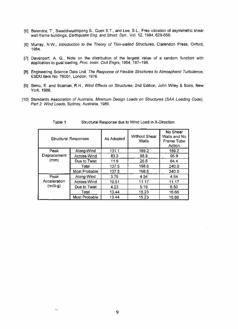
The core wall of the 70-storey building described earlier is placed eccentrically due mainly to architectural requirements. The adverse effect of this eccentricity is reduced greatly through the introduction of a series of shear walls strategically located in the lower floors and the introduction of intermediate periphery columns in the frame tubes above the thirteenth floor. To demonstrate the effectiveness of these remedial measures, the responses under the same wind load environment of the following three structural systems are carried out. They are i) the system as adopted for construction, ii) the adopted system but without the presence of shear walls in the lower floors and iii) as in ii) but with no contribution from the tube actions. The results based on ~ y=~ e =0.02 are
tabulated in Table 1. Actions resulting from the frame tubes configuration in the upper portion of the building reduce greatly the peak displacement due to twisting from 64 mm to 27 mm. The value decreases further to about 12 mm with the presence of heavy walls at the lower level. These shear walls also reduce substantially the along-wind peak displacement from 189 mm to 131 mm. The effect on the cross-wind peak displacement as well as peak acceleration at the top of the building is less pronounced. The peak displacement of 137.5 mm and the maximum acceleration of 13.44 milli-g of the building as constructed are within the acceptable ranges of values in common practice.
6. Concluding Remarks
The adopted structural system should provide efficient and cost effective resistance to lateral loads which can be achieved through (i) torsionally rigid closed frame tube comprising deep spandrel beams and flat columns at the periphery and/or bundle of frame tubes and (ii) proper distribution of flexural and shear stiffnesses of the building such that under lateral load, it will deflect mainly in the direction of the applied force without inducing substantial response in the transverse direction and/or twist as shown in Fig. 12 for the building discussed. The structural vibration due to wind load must satisfy reqUirements for comfort criteria and human perception to horizontal acceleration. Design of buildings, excepting the frame tube members and the shear walls, specially in mild wind environment and low seismic zone is usually proportioned initially on gravity loads and checked against lateral actions using established computer programmes with increased allowable stresses or reduced load factor for lateral loading. In the latter case, additional reinforcement and/or increase in member sizes may be required. Up-down approach allows the construction of the substructure and superstructure to proceed concurrently reducing the construction time by 10 - 20%. Spaces for storage and parking are immediately available once the construction of each basement is completed. This is an important factor to be considered in the construction of any medium or tall buildings in a small site in the centre of the city where working and storage space is at a premium.
7. References
[1] Lee, S.L., Yong, K.Y., Swaddiwudhipong, S., Sitichaikasem, S. and Ratanaprichavej, R., Structural Design and Construction of 70-storey Concrete Building. Special Lecture, Proc. JCI Annual Convention, Fukuoka, Japan Concrete Institute, 1992, 1-41.
[2] Lee, S.L., Yong, K.Y. and Swaddiwudhipong, S., Up-Down Construction of Tall Building. The Third Professor Chin Fung Kee Memorial Lecture, Kuala Lumpur, Malaysia. Also published in Journal of the Institution of Engineers, Malaysia, No. 53, 1993,3-14
[3] Lee, S.L., Swaddiwudhipong, S. and Yong, K.Y., Up-Down Construction of Tall Buildings with Deep Basement. Proc. Concrete 95: Toward Better Concrete Structures, Brisbane, Australia, 1995,1-15.
[4] Lee, S.L. and Swaddiwudhipong, S., Up-Down Construction of Tall Buildings in City Centre. Proc. Int. Conf. on Urban Engineering in Asian Cities in the 21st Century, Vol. 1, Bangkok, Thailand, 1996,22-45.
8
[5] Balendra, T., Swaddiwudhipong S., Quek S.T., and Lee, S.L., Free vibration of asymmetric shear wall-frame buildings, Earthquake Eng. and Struct. Dyn., Vol. 12, 1984,629-650.
[6] Murray, N.W., Introduction to the Theory of Thin-walled Structures, Clarendon Press, Oxford, 1984.
[7] Davenport, A. G., Note on the distribution of the largest value of a random function with application to gust loading, Proc. Instn. Civil Engrs, 1964, 187-196.
[8] Engineering Science Data Unit, The Response of Flexible Structures to Atmospheric Turbulence, ESDU Item No. 76001, London, 1976.
[9] Simiu, E. and Scanlan, R.H., Wind Effects on Structures, 2nd Edition, John Wiley & Sons, New York,1986.
[10] Standards Association of Australia, Minimum Design Loads on Structures (SAA Loading Code), Part 2: Wind Loads, Sydney, Australia, 1989.
Table 1 Structural Response due to Wind Load in X-Direction
No Shear
Structural Responses As Adopted Without Shear Walls and No
Walls Frame Tube Action
Peak AlonQ-Wind 131.1 189.2 189.2 Displacement Across-Wind 83.3 95.9 95.9
(mm) Due to Twist 11.9 26.6 64.4 Total 137.5 198.6 240.0
Most Probable 137.5 198.6 240.0 Peak Along-Wind 3.79 4.54 4.54
Acceleration Across-Wind 10.51 11.17 11.17 (milli-g) Due to Twist 4.23 5.19 6.50
Total 13.44 15.23 16.66 Most Probable 13.44 15.23 16.66
9
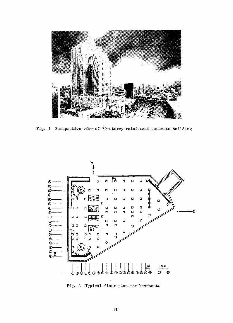
Fig. 1 Perspective view of 70-storey reinforced concrete building
Y
t I
®-- 0 0 0 0
~ ©--- o . 0 0 0 0 0 0
~ o~ ®--- 0 0 0 0 0
(f}-- 0
®-- O~ 0 0 0 0 0
®--- 0 0 0 0 0 "'X CD-- o 0 O.~OO 0
CD--- 0 0
®-- 00 o lii9 0 0
<D--®--- 00 0 0
®-- . 0 0
®-:-CD--
~
11llll1ll~111llllli H Fig. 2 Typical floor plan for basements
10
®-®-<D®-®-(f)--
®-®-<D-CD-®-<D-®--®-@--
®--
~
®-<D-©-®-<E>--.(f)--
®-®--CD-CD-®-<D-®-®-@--
®--
~
~o
.. x
UlUHHHlHUlH H Fig. 3 Typical floor. plan, 1st to 5th floors
Fig. 4 Typical floor plan, 5th to 13th floors
11
~ ®-©-@--
~ ®---®-®-(j)-
Q)-
®-(i)--
®-®-@--
®--
:n= lllllllllllllllll~
Fig. 5 Typical flQor plan, 13th to 45th floors
@-
<D-CD-(])--
®--~ ©-<ID-CD-Q)--
<ID-@--
®-®-@-Q}--
~
...... x
.Frame tube 1
Fig. 6 Typical floor plan above 52nd storey
12
EACH STOREY HElGHT
~lfF (mml ---
3500
13/F 5500
- 1.300
2800
S/F
1.300 lIf --5500
2800 ·8AS~
- -f-- -f-- -f-, ,f-'- '-l-t-t-f-t-rl-I-t-f-I-t-f-~-r~ t-t-f-
t-r-f-
~ t-
r- r-
1/ 1\ l/ 1\ VI" V 1'\ V['\ It·'\ V['\ lL'\
1/1\ 1/1\ V[\ l/['\ V"\ /1\.
- ~ @~ tJ\J b©
{al
Fig. 7
{hI o
(c)
Frame elevation showing K-bracings (a) along grid line 19, (b) along grid lines 11, 13 and 15 (c) K-braced frame
Fig. 8 Periphery frame tube and flat beam-slab system
13
(a) Frame deformed in a shear mode
+
(b) Wall deformed ~n· a flexure mode
7 7T r.7
(c) Deformation of frame shear wall structure in a shear-flexure mode
Fig. 9 Behaviour of frame shear wall structure under lateral load
I' A '/ p
Fig. 10 Panel of frame structure
rI I J I I I 1 I 1 1 I
·1 f I I 1
-
r I I I I r -
-1 r-r .il I r-' -I- -~[JJ11 1 1-- . L_.JL.Jj
y
'I t I
1 I 1 I I
--------t:--------I I , 'I
1
I I
I r---I I I
1 1 I J I -+-1
r-n ~r-1 I ld::I.J_ I L_J 1 I
1--1
.. { 1---------., -------' I I I
I I
1 I I I I
= -.I (a) L __ L-________ ...1 (b)
Fig. 11 Structural plan showing displacement under lateral force in (a) x-direction and (b) y-direction
14